261
15. LADDER LOGIC FUNCTIONS
15.1 INTRODUCTION
Ladder logic input contacts and output coils allow simple logical decisions. Functions extend basic ladder logic to allow other types of control. For example, the addition of timers and counters allowed event based control. A longer list of functions is shown in Figure 201. Combinatorial Logic and Event functions have already been covered. This chapter will discuss Data Handling and Numerical Logic. The next chapter will cover Lists and Program Control and some of the Input and Output func-tions. Remaining functions will be discussed in later chapters.
Topics:
Objectives:• To understand basic functions that allow calculations and comparisons• To understand array functions using memory files
• Functions for data handling, mathematics, conversions, array operations, statis-tics, comparison and Boolean operations.
• Design examples
262
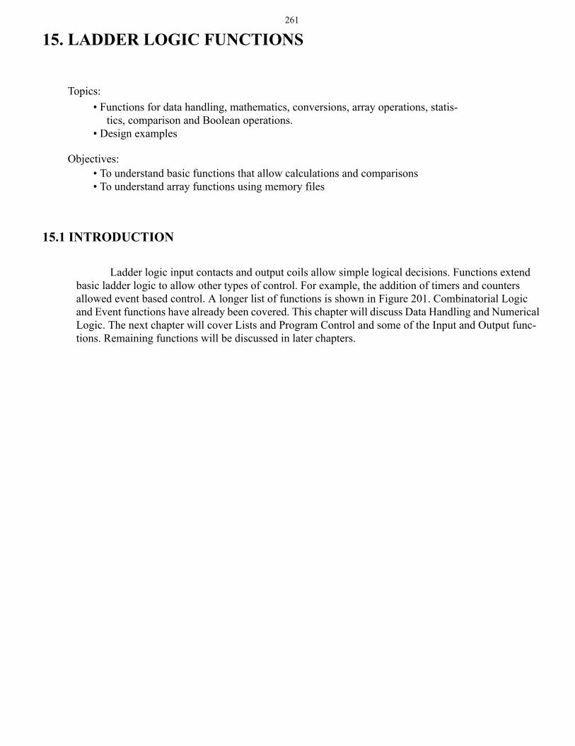
Figure 201 Basic PLC Function Categories
Most of the functions will use PLC memory locations to get values, store values and track func-tion status. Most function will normally become active when the input is true. But, some functions, such as TOF timers, can remain active when the input is off. Other functions will only operate when the input goes from false to true, this is known as positive edge triggered. Consider a counter that only counts when the input goes from false to true, the length of time the input is true does not change the function behavior. A negative edge triggered function would be triggered when the input goes from true to false. Most functions are not edge triggered: unless stated assume functions are not edge triggered.
Combinatorial Logic- relay contacts and coils
Events- timer instructions- counter instructions
Data Handling- moves- mathematics- conversions
Numerical Logic- boolean operations- comparisons
Lists- shift registers/stacks- sequencers
Program Control- branching/looping- immediate inputs/outputs- fault/interrupt detection
Input and Output- PID- communications- high speed counters- ASCII string functions
NOTE: I do not draw functions exactly as they appear in manuals and programming soft-ware. This helps save space and makes the instructions somewhat easier to read. All of the necessary information is given.
263
15.2 DATA HANDLING
15.2.1 Move Functions
There are two basic types of move functions;
MOV(value,destination) - moves a value to a memory locationMVM(value,mask,destination) - moves a value to a memory location, but with a mask to select
specific bits.
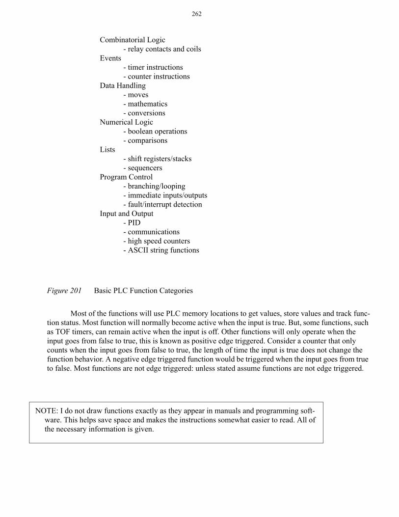
The simple MOV will take a value from one location in memory and place it in another mem-ory location. Examples of the basic MOV are given in Figure 202. When A is true the MOV function moves a floating point number from the source to the destination address. The data in the source address is left unchanged. When B is true the floating point number in the source will be converted to an integer and stored in the destination address in integer memory. The floating point number will be rounded up or down to the nearest integer. When C is true the integer value of 123 will be placed in the integer file test_int.
Figure 202 Examples of the MOV Function
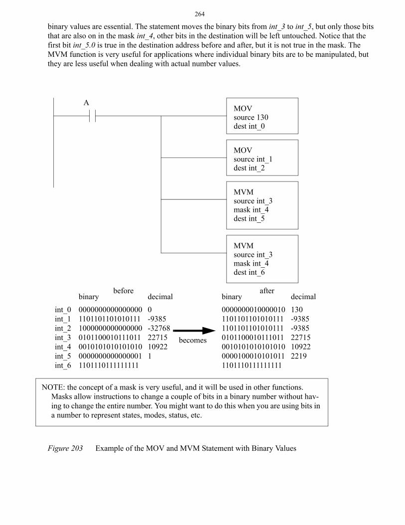
A more complex example of move functions is given in Figure 203. When A becomes true the first move statement will move the value of 130 into int_0. And, the second move statement will move the value of -9385 from int_1 to int_2. (Note: The number is shown as negative because we are using 2s compliment.) For the simple MOVs the binary values are not needed, but for the MVM statement the
MOVSource test_real_1Destination test_real_2
A
MOVSource test_real_1Destination test_int
B
MOVSource 123Destination test_int
C
NOTE: when a function changes a value, except for inputs and outputs, the value is changed immediately. Consider Figure 202, if A, B and C are all true, then the value in test_real_2 will change before the next instruction starts. This is different than the input and output scans that only happen before and after the logic scan.
264
binary values are essential. The statement moves the binary bits from int_3 to int_5, but only those bits that are also on in the mask int_4, other bits in the destination will be left untouched. Notice that the first bit int_5.0 is true in the destination address before and after, but it is not true in the mask. The MVM function is very useful for applications where individual binary bits are to be manipulated, but they are less useful when dealing with actual number values.
Figure 203 Example of the MOV and MVM Statement with Binary Values
MOVsource 130dest int_0
MOVsource int_1dest int_2
MVMsource int_3mask int_4dest int_5
0000000000000000110110110101011110000000000000000101100010111011001010101010101000000000000000011101110111111111
int_0int_1int_2int_3int_4int_5int_6
before
0000000010000010110110110101011111011011010101110101100010111011001010101010101000001000101010111101110111111111
after
A
binary binary0-9385-3276822715109221
decimal130-9385-938522715109222219
decimal
becomes
MVMsource int_3mask int_4dest int_6
NOTE: the concept of a mask is very useful, and it will be used in other functions. Masks allow instructions to change a couple of bits in a binary number without hav-ing to change the entire number. You might want to do this when you are using bits in a number to represent states, modes, status, etc.
265
15.2.2 Mathematical Functions
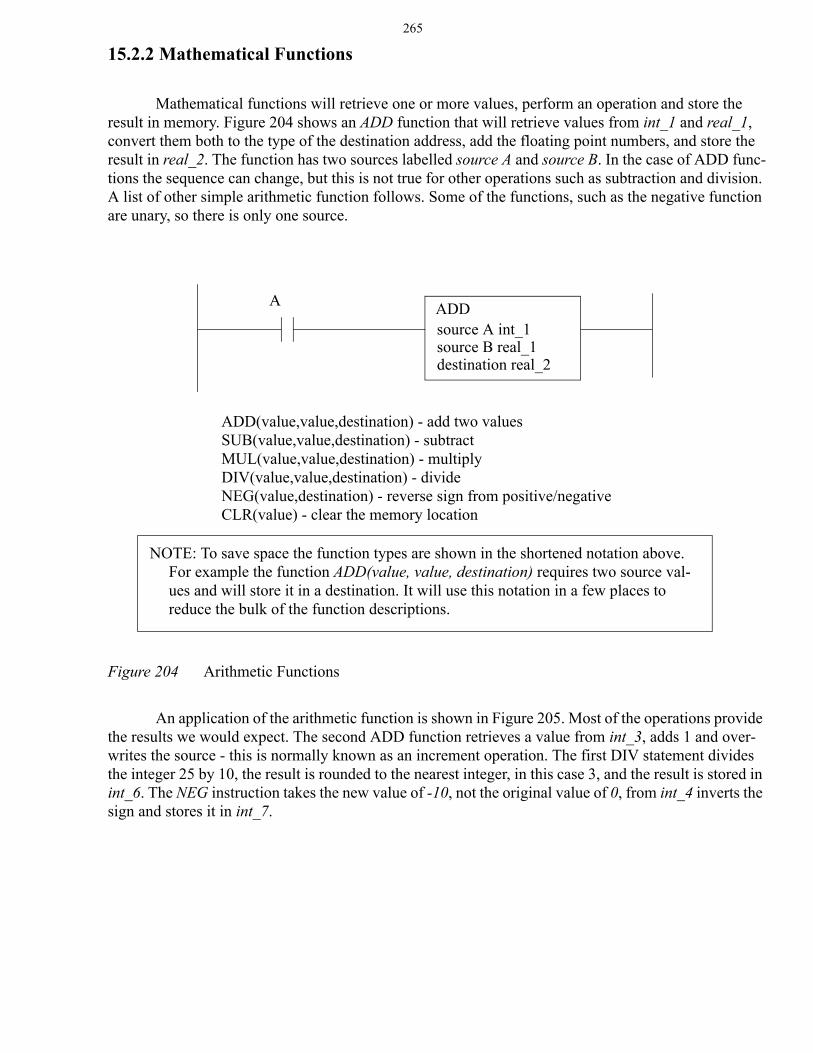
Mathematical functions will retrieve one or more values, perform an operation and store the result in memory. Figure 204 shows an ADD function that will retrieve values from int_1 and real_1, convert them both to the type of the destination address, add the floating point numbers, and store the result in real_2. The function has two sources labelled source A and source B. In the case of ADD func-tions the sequence can change, but this is not true for other operations such as subtraction and division. A list of other simple arithmetic function follows. Some of the functions, such as the negative function are unary, so there is only one source.
Figure 204 Arithmetic Functions
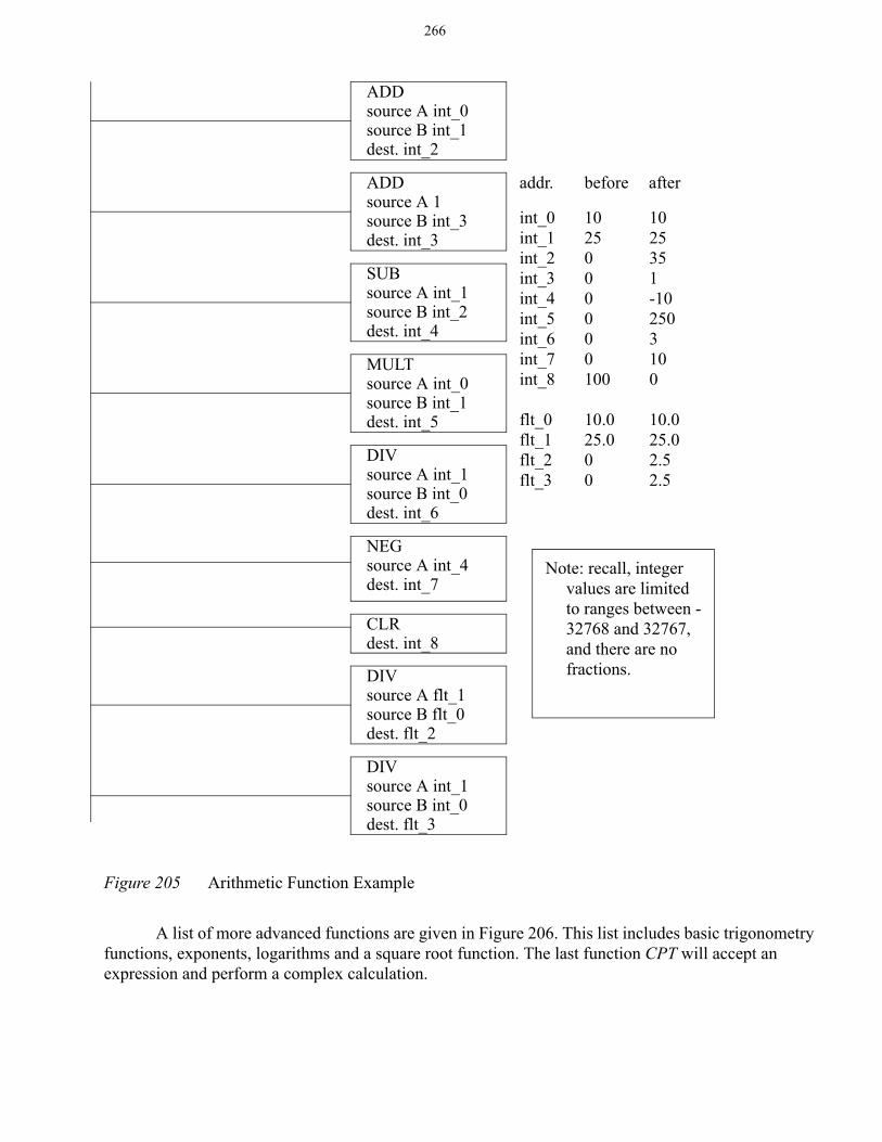
An application of the arithmetic function is shown in Figure 205. Most of the operations provide the results we would expect. The second ADD function retrieves a value from int_3, adds 1 and over-writes the source - this is normally known as an increment operation. The first DIV statement divides the integer 25 by 10, the result is rounded to the nearest integer, in this case 3, and the result is stored in int_6. The NEG instruction takes the new value of -10, not the original value of 0, from int_4 inverts the sign and stores it in int_7.
ADDsource A int_1source B real_1destination real_2
A
ADD(value,value,destination) - add two valuesSUB(value,value,destination) - subtractMUL(value,value,destination) - multiplyDIV(value,value,destination) - divideNEG(value,destination) - reverse sign from positive/negativeCLR(value) - clear the memory location
NOTE: To save space the function types are shown in the shortened notation above. For example the function ADD(value, value, destination) requires two source val-ues and will store it in a destination. It will use this notation in a few places to reduce the bulk of the function descriptions.
266
Figure 205 Arithmetic Function Example
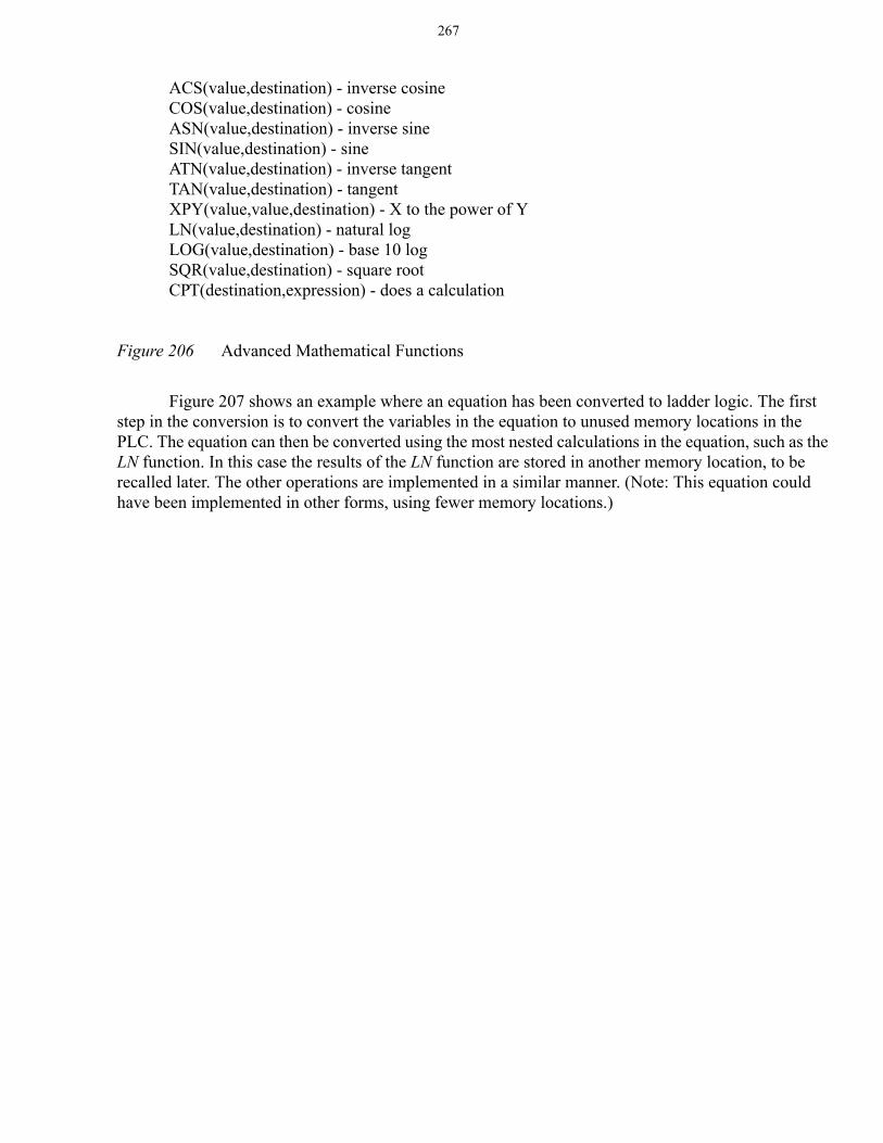
A list of more advanced functions are given in Figure 206. This list includes basic trigonometry functions, exponents, logarithms and a square root function. The last function CPT will accept an expression and perform a complex calculation.
ADDsource A int_0source B int_1dest. int_2
ADDsource A 1source B int_3dest. int_3
SUBsource A int_1source B int_2dest. int_4
MULTsource A int_0source B int_1dest. int_5
DIVsource A int_1source B int_0dest. int_6
NEGsource A int_4dest. int_7
CLRdest. int_8
DIVsource A flt_1source B flt_0dest. flt_2
DIVsource A int_1source B int_0dest. flt_3
int_0int_1int_2int_3int_4int_5int_6int_7int_8
flt_0flt_1flt_2flt_3
1025000000100
10.025.000
1025351-102503100
10.025.02.52.5
addr. before after
Note: recall, integer values are limited to ranges between -32768 and 32767, and there are no fractions.
267
Figure 206 Advanced Mathematical Functions
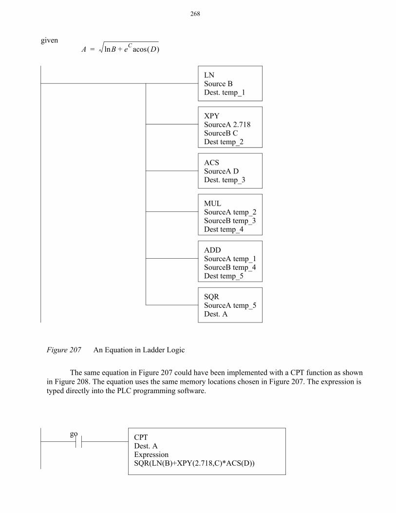
Figure 207 shows an example where an equation has been converted to ladder logic. The first step in the conversion is to convert the variables in the equation to unused memory locations in the PLC. The equation can then be converted using the most nested calculations in the equation, such as the LN function. In this case the results of the LN function are stored in another memory location, to be recalled later. The other operations are implemented in a similar manner. (Note: This equation could have been implemented in other forms, using fewer memory locations.)
ACS(value,destination) - inverse cosineCOS(value,destination) - cosineASN(value,destination) - inverse sineSIN(value,destination) - sineATN(value,destination) - inverse tangentTAN(value,destination) - tangentXPY(value,value,destination) - X to the power of YLN(value,destination) - natural logLOG(value,destination) - base 10 logSQR(value,destination) - square rootCPT(destination,expression) - does a calculation
268
Figure 207 An Equation in Ladder Logic
The same equation in Figure 207 could have been implemented with a CPT function as shown in Figure 208. The equation uses the same memory locations chosen in Figure 207. The expression is typed directly into the PLC programming software.
A Bln eC D( )acos+=given
LNSource BDest. temp_1
XPYSourceA 2.718SourceB CDest temp_2
ACSSourceA DDest. temp_3
MULSourceA temp_2SourceB temp_3Dest temp_4
ADDSourceA temp_1SourceB temp_4Dest temp_5
SQRSourceA temp_5Dest. A
CPTDest. AExpressionSQR(LN(B)+XPY(2.718,C)*ACS(D))
go
269
Figure 208 Calculations with a Compute Function
Math functions can result in status flags such as overflow, carry, etc. care must be taken to avoid problems such as overflows. These problems are less common when using floating point numbers. Inte-gers are more prone to these problems because they are limited to the range.
15.2.3 Conversions
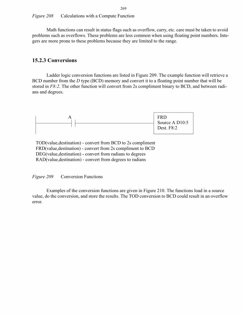
Ladder logic conversion functions are listed in Figure 209. The example function will retrieve a BCD number from the D type (BCD) memory and convert it to a floating point number that will be stored in F8:2. The other function will convert from 2s compliment binary to BCD, and between radi-ans and degrees.
Figure 209 Conversion Functions
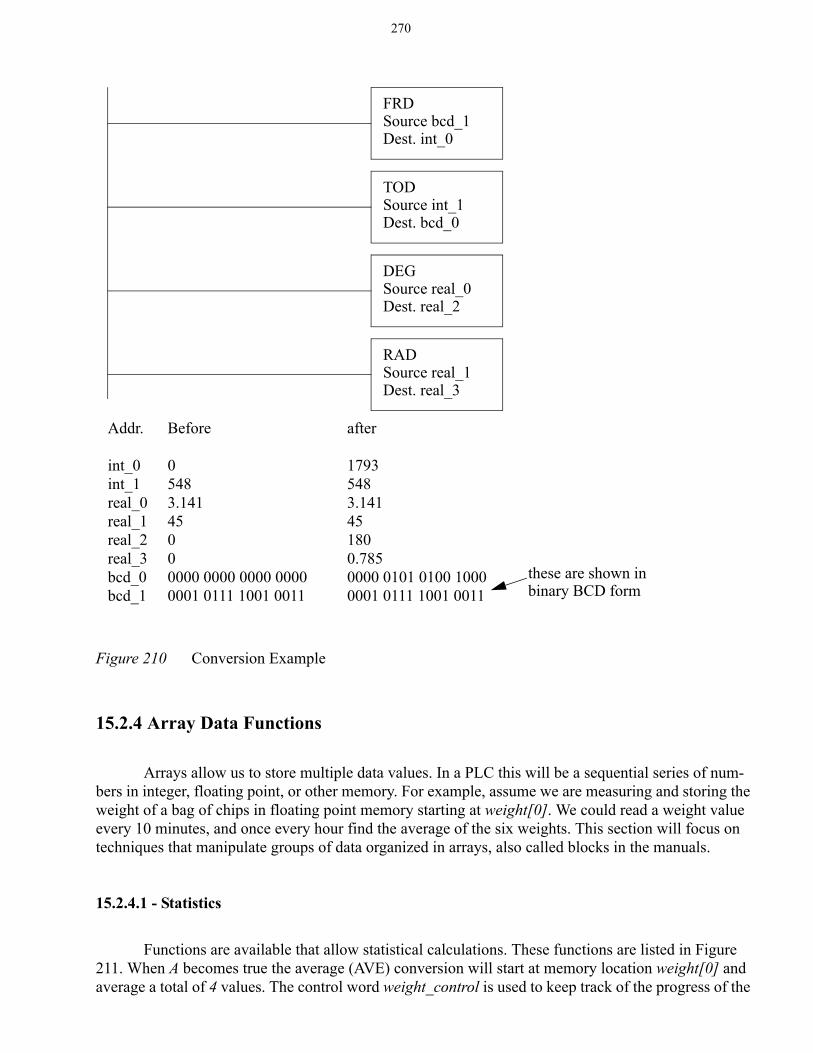
Examples of the conversion functions are given in Figure 210. The functions load in a source value, do the conversion, and store the results. The TOD conversion to BCD could result in an overflow error.
TOD(value,destination) - convert from BCD to 2s complimentFRD(value,destination) - convert from 2s compliment to BCDDEG(value,destination) - convert from radians to degreesRAD(value,destination) - convert from degrees to radians
FRDSource A D10:5Dest. F8:2
A
270
Figure 210 Conversion Example
15.2.4 Array Data Functions
Arrays allow us to store multiple data values. In a PLC this will be a sequential series of num-bers in integer, floating point, or other memory. For example, assume we are measuring and storing the weight of a bag of chips in floating point memory starting at weight[0]. We could read a weight value every 10 minutes, and once every hour find the average of the six weights. This section will focus on techniques that manipulate groups of data organized in arrays, also called blocks in the manuals.
15.2.4.1 - Statistics
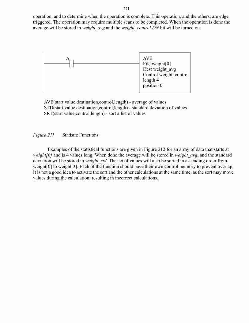
Functions are available that allow statistical calculations. These functions are listed in Figure 211. When A becomes true the average (AVE) conversion will start at memory location weight[0] and average a total of 4 values. The control word weight_control is used to keep track of the progress of the
FRDSource bcd_1Dest. int_0
TODSource int_1Dest. bcd_0
DEGSource real_0Dest. real_2
RADSource real_1Dest. real_3
Addr.
int_0int_1real_0real_1real_2real_3bcd_0bcd_1
Before
05483.14145000000 0000 0000 00000001 0111 1001 0011
after
17935483.141451800.7850000 0101 0100 10000001 0111 1001 0011
these are shown inbinary BCD form
271
operation, and to determine when the operation is complete. This operation, and the others, are edge triggered. The operation may require multiple scans to be completed. When the operation is done the average will be stored in weight_avg and the weight_control.DN bit will be turned on.
Figure 211 Statistic Functions
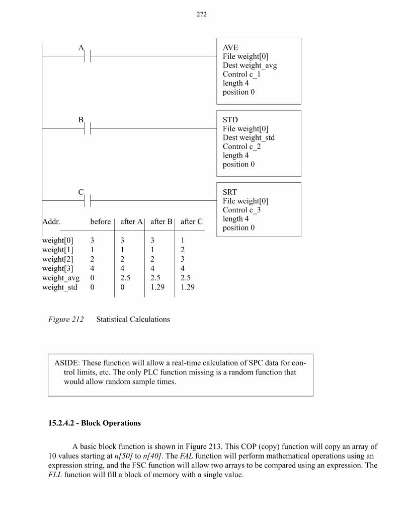
Examples of the statistical functions are given in Figure 212 for an array of data that starts at weight[0] and is 4 values long. When done the average will be stored in weight_avg, and the standard deviation will be stored in weight_std. The set of values will also be sorted in ascending order from weight[0] to weight[3]. Each of the function should have their own control memory to prevent overlap. It is not a good idea to activate the sort and the other calculations at the same time, as the sort may move values during the calculation, resulting in incorrect calculations.
AVE(start value,destination,control,length) - average of valuesSTD(start value,destination,control,length) - standard deviation of valuesSRT(start value,control,length) - sort a list of values
AVEFile weight[0]Dest weight_avgControl weight_controllength 4position 0
A
272
Figure 212 Statistical Calculations
15.2.4.2 - Block Operations
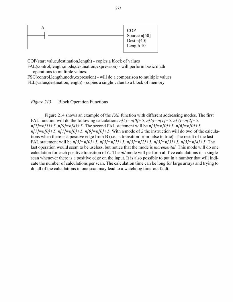
A basic block function is shown in Figure 213. This COP (copy) function will copy an array of 10 values starting at n[50] to n[40]. The FAL function will perform mathematical operations using an expression string, and the FSC function will allow two arrays to be compared using an expression. The FLL function will fill a block of memory with a single value.
AVEFile weight[0]Dest weight_avgControl c_1length 4position 0
STDFile weight[0]Dest weight_stdControl c_2length 4position 0
SRTFile weight[0]Control c_3length 4position 0
Addr.
weight[0]weight[1]weight[2]weight[3]weight_avgweight_std
before
312400
after A
31242.50
A
B
C
after B
31242.51.29
after C
12342.51.29
ASIDE: These function will allow a real-time calculation of SPC data for con-trol limits, etc. The only PLC function missing is a random function that would allow random sample times.
273
Figure 213 Block Operation Functions
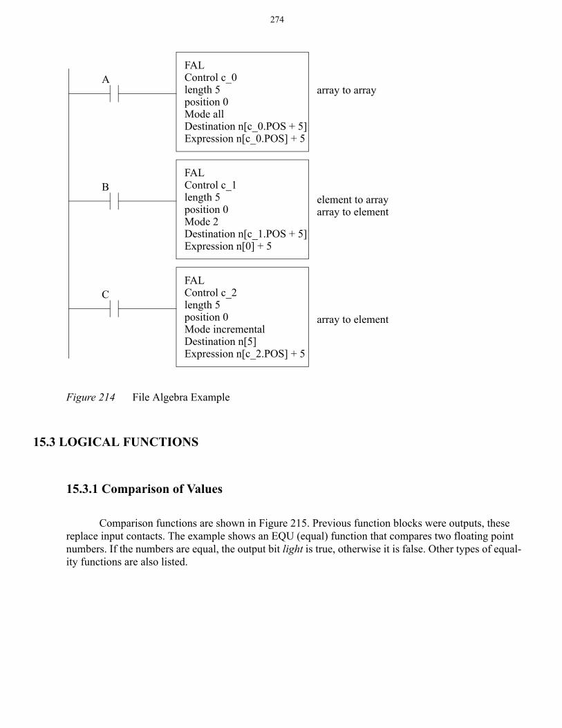
Figure 214 shows an example of the FAL function with different addressing modes. The first FAL function will do the following calculations n[5]=n[0]+5, n[6]=n[1]+5, n[7]=n[2]+5, n[7]=n[3]+5, n[9]=n[4]+5. The second FAL statement will be n[5]=n[0]+5, n[6]=n[0]+5, n[7]=n[0]+5, n[7]=n[0]+5, n[9]=n[0]+5. With a mode of 2 the instruction will do two of the calcula-tions when there is a positive edge from B (i.e., a transition from false to true). The result of the last FAL statement will be n[5]=n[0]+5, n[5]=n[1]+5, n[5]=n[2]+5, n[5]=n[3]+5, n[5]=n[4]+5. The last operation would seem to be useless, but notice that the mode is incremental. This mode will do one calculation for each positive transition of C. The all mode will perform all five calculations in a single scan whenever there is a positive edge on the input. It is also possible to put in a number that will indi-cate the number of calculations per scan. The calculation time can be long for large arrays and trying to do all of the calculations in one scan may lead to a watchdog time-out fault.
COP(start value,destination,length) - copies a block of valuesFAL(control,length,mode,destination,expression) - will perform basic math
operations to multiple values.FSC(control,length,mode,expression) - will do a comparison to multiple valuesFLL(value,destination,length) - copies a single value to a block of memory
COPSource n[50]Dest n[40]Length 10
A
274
Figure 214 File Algebra Example
15.3 LOGICAL FUNCTIONS
15.3.1 Comparison of Values
Comparison functions are shown in Figure 215. Previous function blocks were outputs, these replace input contacts. The example shows an EQU (equal) function that compares two floating point numbers. If the numbers are equal, the output bit light is true, otherwise it is false. Other types of equal-ity functions are also listed.
FALControl c_0length 5position 0Mode allDestination n[c_0.POS + 5]Expression n[c_0.POS] + 5
FALControl c_1length 5position 0Mode 2Destination n[c_1.POS + 5]Expression n[0] + 5
array to array
element to arrayarray to element
FALControl c_2length 5position 0Mode incrementalDestination n[5]Expression n[c_2.POS] + 5
array to element
A
B
C
275
Figure 215 Comparison Functions
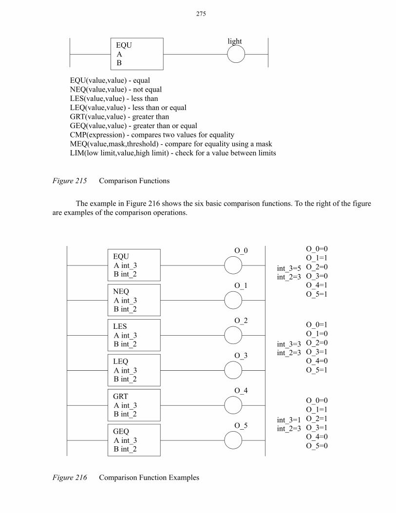
The example in Figure 216 shows the six basic comparison functions. To the right of the figure are examples of the comparison operations.
Figure 216 Comparison Function Examples
EQU(value,value) - equalNEQ(value,value) - not equalLES(value,value) - less thanLEQ(value,value) - less than or equalGRT(value,value) - greater thanGEQ(value,value) - greater than or equalCMP(expression) - compares two values for equalityMEQ(value,mask,threshold) - compare for equality using a maskLIM(low limit,value,high limit) - check for a value between limits
EQUA B
light
EQUA int_3B int_2
O_0
NEQA int_3B int_2
O_1
LESA int_3B int_2
O_2
LEQA int_3B int_2
O_3
GRTA int_3B int_2
O_4
GEQA int_3B int_2
O_5
O_0=0O_1=1O_2=0O_3=0O_4=1O_5=1
int_3=5int_2=3
O_0=1O_1=0O_2=0O_3=1O_4=0O_5=1
int_3=3int_2=3
O_0=0O_1=1O_2=1O_3=1O_4=0O_5=0
int_3=1int_2=3
276
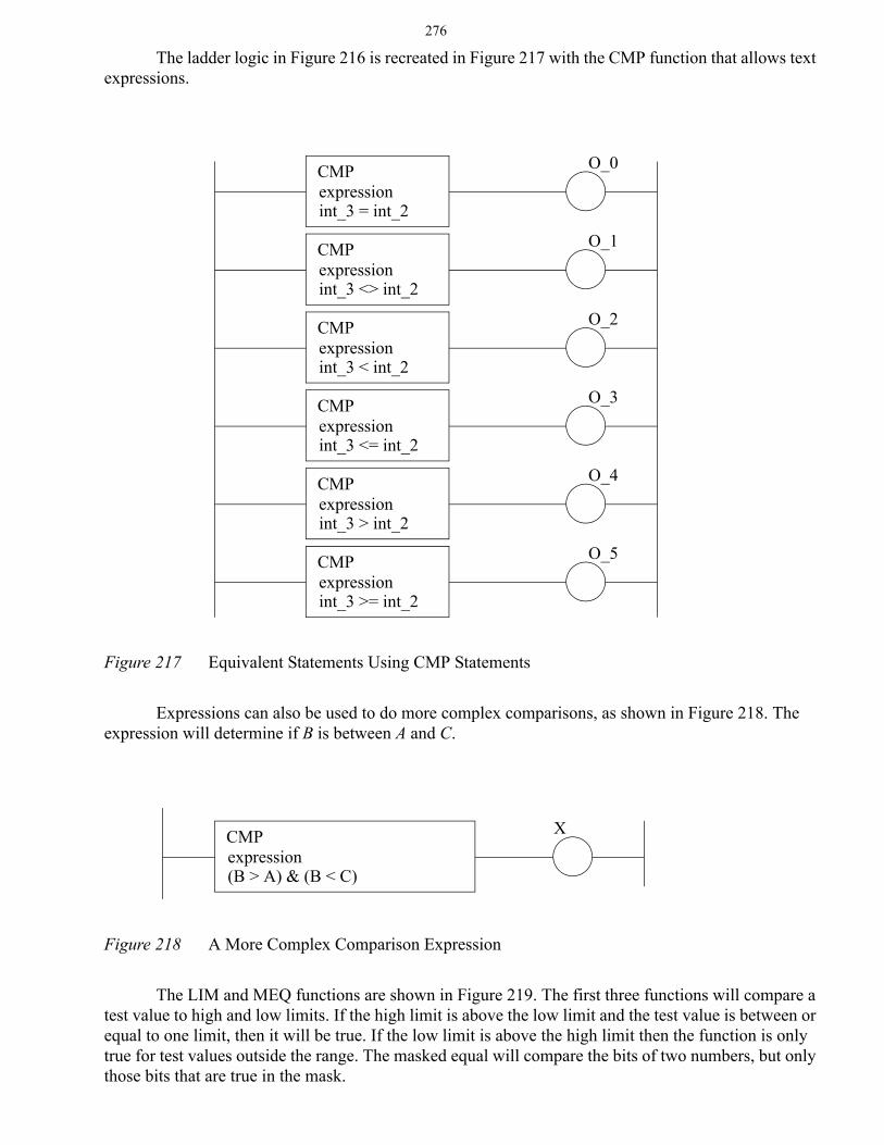
The ladder logic in Figure 216 is recreated in Figure 217 with the CMP function that allows text expressions.
Figure 217 Equivalent Statements Using CMP Statements
Expressions can also be used to do more complex comparisons, as shown in Figure 218. The expression will determine if B is between A and C.
Figure 218 A More Complex Comparison Expression
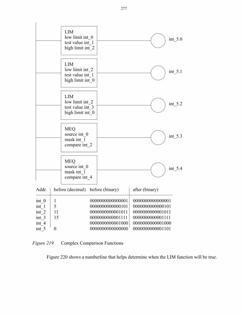
The LIM and MEQ functions are shown in Figure 219. The first three functions will compare a test value to high and low limits. If the high limit is above the low limit and the test value is between or equal to one limit, then it will be true. If the low limit is above the high limit then the function is only true for test values outside the range. The masked equal will compare the bits of two numbers, but only those bits that are true in the mask.
CMPexpressionint_3 = int_2
O_0
CMPexpressionint_3 <> int_2
O_1
CMPexpressionint_3 < int_2
O_2
CMPexpressionint_3 <= int_2
O_3
CMPexpressionint_3 > int_2
O_4
CMPexpressionint_3 >= int_2
O_5
CMPexpression(B > A) & (B < C)
X
277
Figure 219 Complex Comparison Functions
Figure 220 shows a numberline that helps determine when the LIM function will be true.
LIMlow limit int_0test value int_1high limit int_2
int_5.0
LIMlow limit int_2test value int_1high limit int_0
int_5.1
LIMlow limit int_2test value int_3high limit int_0
int_5.2
MEQsource int_0mask int_1compare int_2
int_5.3
Addr.
int_0int_1int_2int_3int_4int_5
before (decimal)
151115
0
after (binary)
000000000000000100000000000001010000000000001011000000000000111100000000000010000000000000001101
before (binary)
000000000000000100000000000001010000000000001011000000000000111100000000000010000000000000000000
MEQsource int_0mask int_1compare int_4
int_5.4
278
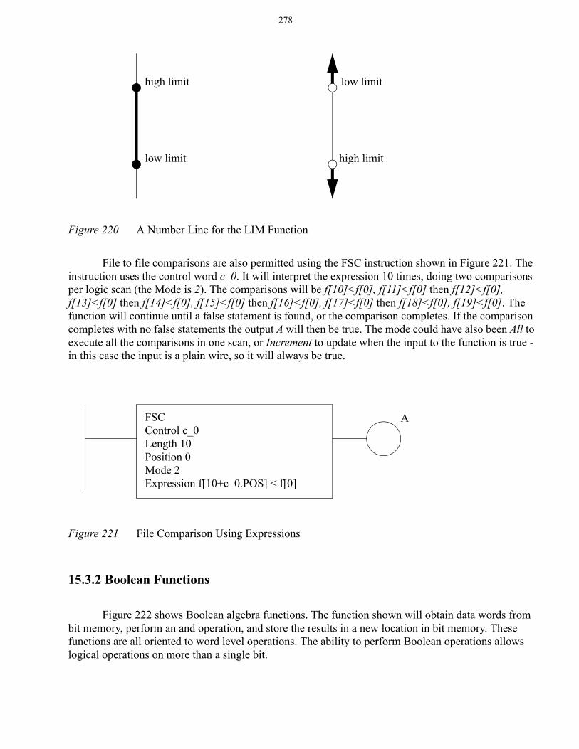
Figure 220 A Number Line for the LIM Function
File to file comparisons are also permitted using the FSC instruction shown in Figure 221. The instruction uses the control word c_0. It will interpret the expression 10 times, doing two comparisons per logic scan (the Mode is 2). The comparisons will be f[10]<f[0], f[11]<f[0] then f[12]<f[0], f[13]<f[0] then f[14]<f[0], f[15]<f[0] then f[16]<f[0], f[17]<f[0] then f[18]<f[0], f[19]<f[0]. The function will continue until a false statement is found, or the comparison completes. If the comparison completes with no false statements the output A will then be true. The mode could have also been All to execute all the comparisons in one scan, or Increment to update when the input to the function is true - in this case the input is a plain wire, so it will always be true.
Figure 221 File Comparison Using Expressions
15.3.2 Boolean Functions
Figure 222 shows Boolean algebra functions. The function shown will obtain data words from bit memory, perform an and operation, and store the results in a new location in bit memory. These functions are all oriented to word level operations. The ability to perform Boolean operations allows logical operations on more than a single bit.
high limit
low limit
low limit
high limit
FSCControl c_0Length 10Position 0Mode 2Expression f[10+c_0.POS] < f[0]
A
279
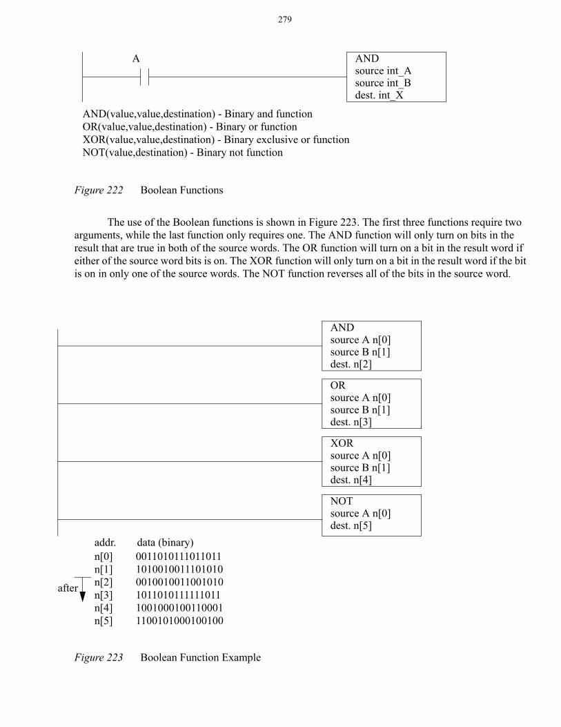
Figure 222 Boolean Functions
The use of the Boolean functions is shown in Figure 223. The first three functions require two arguments, while the last function only requires one. The AND function will only turn on bits in the result that are true in both of the source words. The OR function will turn on a bit in the result word if either of the source word bits is on. The XOR function will only turn on a bit in the result word if the bit is on in only one of the source words. The NOT function reverses all of the bits in the source word.
Figure 223 Boolean Function Example
AND(value,value,destination) - Binary and functionOR(value,value,destination) - Binary or functionXOR(value,value,destination) - Binary exclusive or functionNOT(value,destination) - Binary not function
ANDsource int_Asource int_Bdest. int_X
A
ANDsource A n[0]source B n[1]dest. n[2]
ORsource A n[0]source B n[1]dest. n[3]
XORsource A n[0]source B n[1]dest. n[4]
NOTsource A n[0]dest. n[5]
n[0]n[1]n[2]n[3]n[4]n[5]
001101011101101110100100111010100010010011001010101101011111101110010001001100011100101000100100
addr. data (binary)
after
280
15.4 DESIGN CASES
15.4.1 Simple Calculation
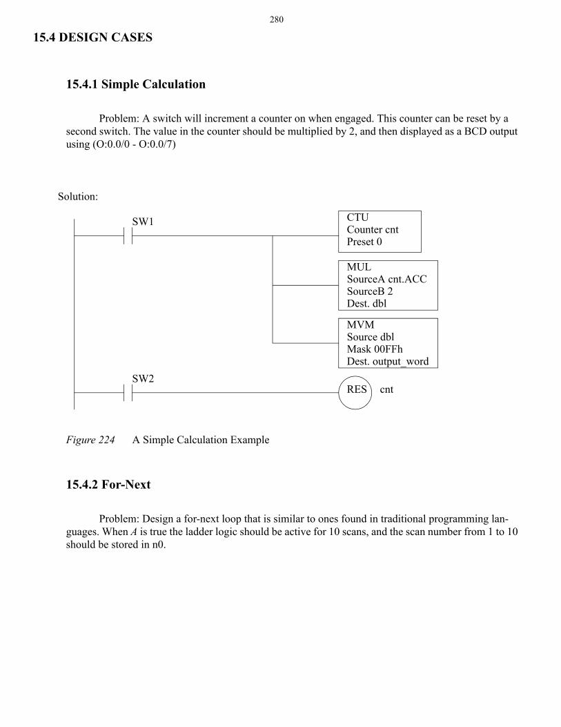
Problem: A switch will increment a counter on when engaged. This counter can be reset by a second switch. The value in the counter should be multiplied by 2, and then displayed as a BCD output using (O:0.0/0 - O:0.0/7)
Figure 224 A Simple Calculation Example
15.4.2 For-Next
Problem: Design a for-next loop that is similar to ones found in traditional programming lan-guages. When A is true the ladder logic should be active for 10 scans, and the scan number from 1 to 10 should be stored in n0.
CTUCounter cntPreset 0
RES cnt
MULSourceA cnt.ACCSourceB 2Dest. dbl
MVMSource dblMask 00FFhDest. output_word
SW1
SW2
Solution:
281
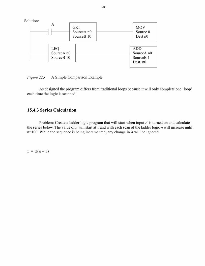
Figure 225 A Simple Comparison Example
As designed the program differs from traditional loops because it will only complete one ’loop’ each time the logic is scanned.
15.4.3 Series Calculation
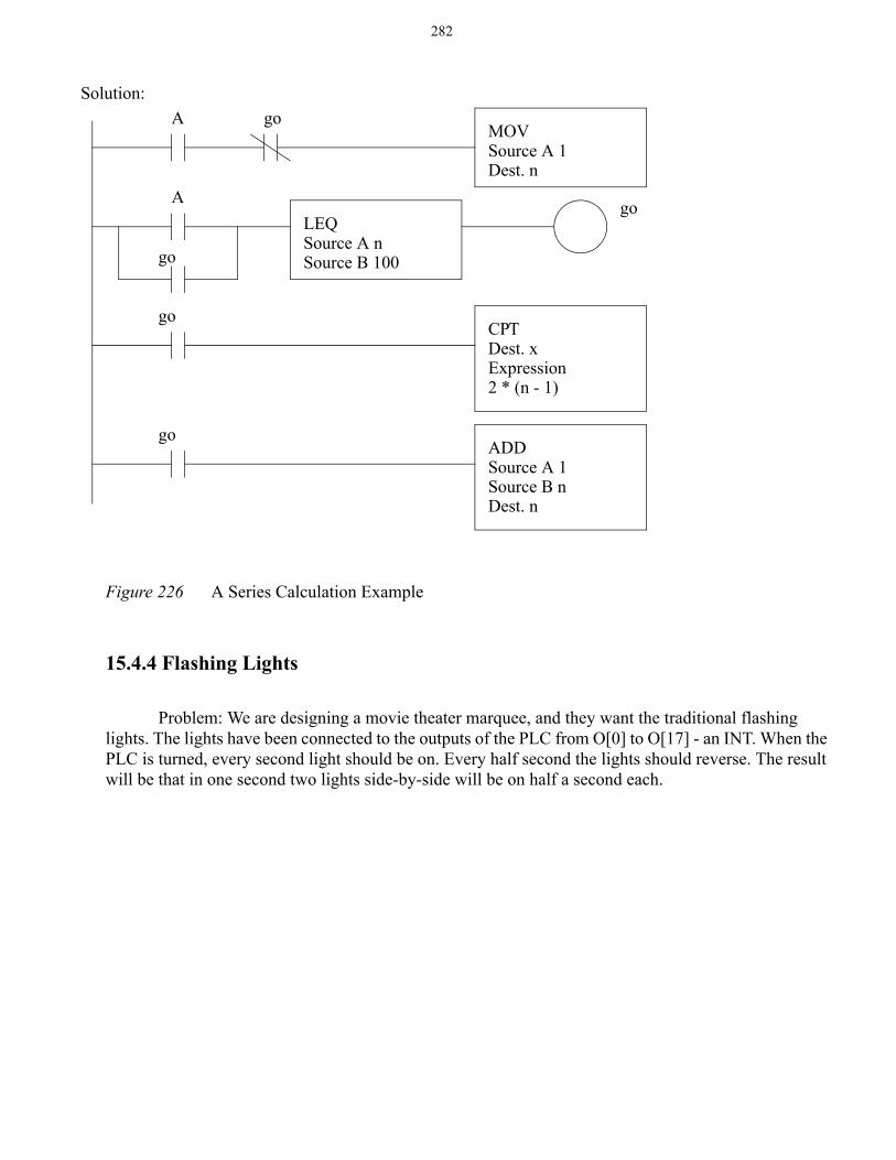
Problem: Create a ladder logic program that will start when input A is turned on and calculate the series below. The value of n will start at 1 and with each scan of the ladder logic n will increase until n=100. While the sequence is being incremented, any change in A will be ignored.
Solution:MOVSource 0Dest n0
AGRTSourceA n0SourceB 10
ADDSourceA n0SourceB 1
LEQSourceA n0SourceB 10
Dest. n0
x 2 n 1–( )=
282
Figure 226 A Series Calculation Example
15.4.4 Flashing Lights
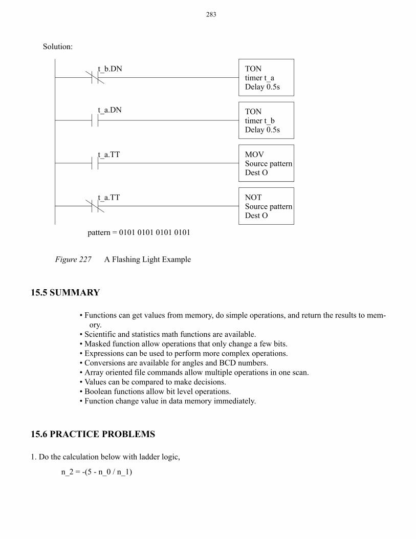
Problem: We are designing a movie theater marquee, and they want the traditional flashing lights. The lights have been connected to the outputs of the PLC from O[0] to O[17] - an INT. When the PLC is turned, every second light should be on. Every half second the lights should reverse. The result will be that in one second two lights side-by-side will be on half a second each.
MOVSource A 1Dest. n
A go
A
go
go
CPTDest. xExpression
go
2 * (n - 1)
ADDSource A 1Source B n
go
Dest. n
LEQSource A nSource B 100
Solution:
283
Figure 227 A Flashing Light Example
15.5 SUMMARY
• Functions can get values from memory, do simple operations, and return the results to mem-ory.
• Scientific and statistics math functions are available.• Masked function allow operations that only change a few bits.• Expressions can be used to perform more complex operations.• Conversions are available for angles and BCD numbers.• Array oriented file commands allow multiple operations in one scan.• Values can be compared to make decisions.• Boolean functions allow bit level operations.• Function change value in data memory immediately.
15.6 PRACTICE PROBLEMS
1. Do the calculation below with ladder logic,
TONtimer t_aDelay 0.5s
TONtimer t_bDelay 0.5s
t_b.DN
t_a.DN
MOVSource patternDest O
t_a.TT
NOTSource patternDest O
t_a.TT
pattern = 0101 0101 0101 0101
Solution:
n_2 = -(5 - n_0 / n_1)
284
2. Implement the following function,
3. A switch will increment a counter on when engaged. This counter can be reset by a second switch. The value in the counter should be multiplied by 5, and then displayed as a binary output using output integer ’O_lights’.
4. Create a ladder logic program that will start when input A is turned on and calculate the series below. The value of n will start at 0 and with each scan of the ladder logic n will increase by 2 until n=20. While the sequence is being incremented, any change in A will be ignored.
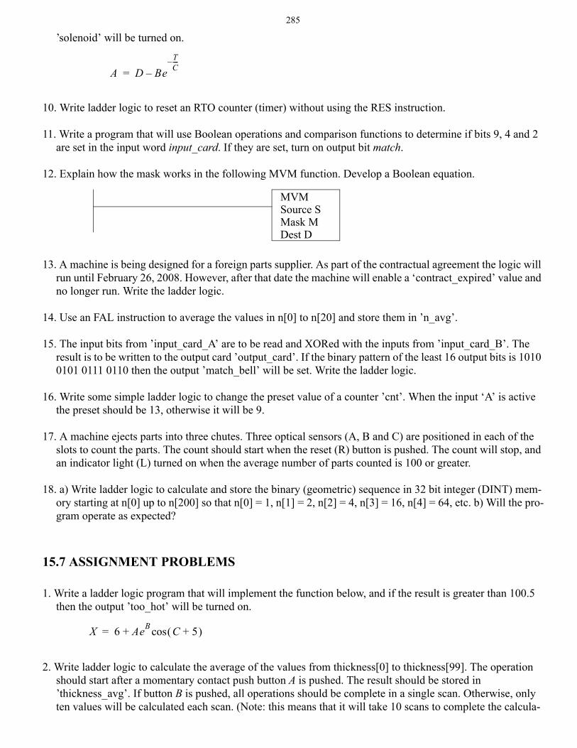
5. The following program uses indirect addressing. Indicate what the new values in memory will be when but-ton A is pushed after the first and second instructions.
6. A thumbwheel input card acquires a four digit BCD count. A sensor detects parts dropping down a chute. When the count matches the BCD value the chute is closed, and a light is turned on until a reset button is pushed. A start button must be pushed to start the part feeding. Develop the ladder logic for this controller. Use a structured design technique such as a state diagram.
7. Describe the difference between incremental, all and a number for file oriented instruction, such as FAL.
8. What is the maximum number of elements that moved with a file instruction? What might happen if too many are transferred in one scan?
9. Write a ladder logic program to do the following calculation. If the result is greater than 20.0, then the output
x y y y( )log+y 1+
------------------------⎝ ⎠⎛ ⎞
⎝ ⎠⎛ ⎞atan=
x 2 n( )log 1–( )=
ADDSource A 1Source B n[0]Dest. n[n[1]]
n[0]n[1]n[2]
1addr before after 1st
2
ADDSource A n[n[0]]Source B n[n[1]]Dest. n[n[0]]
A
A
3
after 2nd
Inputs
bcd_in - BCD input cardpart_detectstart_buttonreset_button
Outputs
chute_openlight
285
’solenoid’ will be turned on.
10. Write ladder logic to reset an RTO counter (timer) without using the RES instruction.
11. Write a program that will use Boolean operations and comparison functions to determine if bits 9, 4 and 2 are set in the input word input_card. If they are set, turn on output bit match.
12. Explain how the mask works in the following MVM function. Develop a Boolean equation.
13. A machine is being designed for a foreign parts supplier. As part of the contractual agreement the logic will run until February 26, 2008. However, after that date the machine will enable a ‘contract_expired’ value and no longer run. Write the ladder logic.
14. Use an FAL instruction to average the values in n[0] to n[20] and store them in ’n_avg’.
15. The input bits from ’input_card_A’ are to be read and XORed with the inputs from ’input_card_B’. The result is to be written to the output card ’output_card’. If the binary pattern of the least 16 output bits is 1010 0101 0111 0110 then the output ’match_bell’ will be set. Write the ladder logic.
16. Write some simple ladder logic to change the preset value of a counter ’cnt’. When the input ‘A’ is active the preset should be 13, otherwise it will be 9.
17. A machine ejects parts into three chutes. Three optical sensors (A, B and C) are positioned in each of the slots to count the parts. The count should start when the reset (R) button is pushed. The count will stop, and an indicator light (L) turned on when the average number of parts counted is 100 or greater.
18. a) Write ladder logic to calculate and store the binary (geometric) sequence in 32 bit integer (DINT) mem-ory starting at n[0] up to n[200] so that n[0] = 1, n[1] = 2, n[2] = 4, n[3] = 16, n[4] = 64, etc. b) Will the pro-gram operate as expected?
15.7 ASSIGNMENT PROBLEMS
1. Write a ladder logic program that will implement the function below, and if the result is greater than 100.5 then the output ’too_hot’ will be turned on.
2. Write ladder logic to calculate the average of the values from thickness[0] to thickness[99]. The operation should start after a momentary contact push button A is pushed. The result should be stored in ’thickness_avg’. If button B is pushed, all operations should be complete in a single scan. Otherwise, only ten values will be calculated each scan. (Note: this means that it will take 10 scans to complete the calcula-
A D BeTC----–
–=
MVMSource SMask MDest D
X 6 AeB C 5+( )cos+=
286
tion if A is pushed.)
3. Write a ladder logic program that will calculate the standard deviation of numbers in the locations f[0] to f[29] without using the STD function.
4. A program is to perform the following actions for a self-service security check. The device will allow bags to be inserted to the test chamber through an entrance door. If the bag passes the check it can be removed through an exit door, otherwise an alarm is sounded. Create a state diagram using the steps below.
1. The machine starts in an ‘idle’ state. The ‘open_entry’ output is activated to open the input door. The ‘open_exit’ output is deactivated to close the output door.
2. When a bag is inserted the ‘bag_detected’ input goes high. The ‘open_entry’ input should be deactivated to close the door.
3. When the ‘entry_door_closed’ and ‘exit_door_closed’ inputs are active then a ‘test’ output will be set high to start a scan of the bags.
4. When the scan of the bags is complete a ‘scan_done’ input is set. The ‘test’ output should be turned off.
5. The scan results in two real values ‘nitrates’ and ‘mass’. The calculation below is performed. If the ‘risk’ is below 0.3, or above 23.5, then the machine enters an alarm state (step 8), oth-erwise it continues to step 6.
6. The ‘open_exit’ output is activated to open the exit door. The machine waits until the ‘bag_detected’ input goes low.
7. The ‘open_exit’ output is deactivated to close the door. The machine waits until the ‘exit_door_closed’ input is high before returning to the ‘idle state.
8. In the alarm state an operator input ‘key’ must be active to open the exit door. After this input is released the door will close and return to the ‘idle’ state.
risk 4nitrates sqrt mass( )nitrates+=
Recommended