
A decision support system for power plant design
F�atima C.C. Dargam *, Erhard W. Perz
SimTech Simulation Technology, Riesstrasse 120, A-8010 Graz, Austria
Received 1 March 1997
Abstract
The design of power plants requires a balanced study of three major considerations, namely: the decision about the
plant lay-out (choice of components and their dispositions); the planning of the plant operational requirements (pro-
vision for maintenance and upratings); and the variation of external conditions, like changes on energy costs or on the
demand rates, for instance. These three aspects must be jointly dealt with, considering both quantitative and qualitative
classi®cations which cover economic and technical requirements of the project design. The available tools for design
and simulation of power plants, provide support for technical quantitative analysis. However, they do not support
the design qualitatively. In this paper, we propose to incorporate a decision support system in a power plant simulation
tool, in order to provide the qualitative synthesis needed for the plant design process, and also to assist the design en-
gineers in performing a better choice-evaluation of the aspects described previously. The paper describes the system's
speci®cation and initial implementation details within the simulation framework of IPSEpro, a programmable integrat-
ed process simulation environment from SimTech. Ó 1998 Elsevier Science B.V. All rights reserved.
Keywords: Decision support systems; Power plant design; Process simulation; Qualitative analysis; Evaluation support;
Knowledge-based support systems
1. Introduction
The ability to model power plant equipmentand complete power plants is essential for optimiz-ing the performance and consequently cuttingdown costs. For many years, computer modelshave been important tools for this area. In the be-ginning, the tendency was for companies to havelarge proprietary programs, implementing their
speci®c design concepts and know-how. The rapiddevelopment of computing technology during re-cent years made maintenance of such programsdi�cult and costly. Nowadays, most of the compa-nies including equipment manufacturers, plant op-erators, and engineering and consultingcompanies, prefer to use modelling environmentsthat allow them to overcome the limits of purposespeci®c solutions. As a consequence, project's per-formance was improved and productivity increas-ing features, like graphic user interfaces ande�cient data exchange with other programs, weremade available to them. An example of a software
European Journal of Operational Research 109 (1998) 310±320
* Corresponding author. Fax: 43 316 386 278/9; e-mail:
0377-2217/98/$19.00 Ó 1998 Elsevier Science B.V. All rights reserved.
PII S 0 3 7 7 - 2 2 1 7 ( 9 8 ) 0 0 0 5 9 - 9
system with these capabilities is SimTech's pack-age IPSEpro.
Designing power plants is a highly domain de-pendent task. It requires a balanced study of threemajor considerations, namely: the decision aboutthe plant lay-out (choice of components and theirdispositions); the planning of the plant operationalrequirements (provision for maintenance and up-ratings); and the variation of external conditions,like changes on energy costs or on the demandrates, for instance. In [1], we ®nd these aspects de-scribed in detail. These three aspects must be joint-ly dealt with, considering both quantitative andqualitative classi®cations which cover economicand technical requirements of the design project.The available tools for design and simulation ofpower plants, provide support for technical quan-titative analysis, but they do not support the de-sign qualitatively. There is a need for theintegration of a design support module into a pow-er plant simulation environment, so that users canbe assisted in performing a better choice-evalua-tion of the aspects described previously. Such asupport system would also provide the qualitativesynthesis needed for the plant design process.
This paper describes the integration of a DesignSupport System to the programmable integratedprocess simulation environment IPSEpro.
2. Related work
In the area of power plant design support, we®nd studies of methodic approaches, like the onepresented in [1], which helps to specify optimizedlay-outs and operation strategies of thermal powerplants. Within such a methodological approach topower plant design, we identify three phases wherea decision support system could be usefully ap-plied:· Providing feasible solutions considering ``triple
variations'' of plant-design parameters, plantoperation parameters, and existing boundaryconditions.
· Providing basis for the implementation of inno-vative solutions, by identifying ``knowledgegaps'' which are required to deal with criticalparts of the project.
· Supporting the plant modelling, in terms ofcomponents choice and qualitative synthesis inorder to meet the expected output parameters,considering the existing boundary conditions.By ``boundary conditions'' we mean, for in-
stance, parameters involving physical, economic,and legal constraints.
In the area of power plant operation support,we know of prototype implementations in termsof decision support systems. As an example we citethe work in [2], where they describe the develop-ment of a knowledge-based operator support sys-tem for small cogeneration plants. The objectiveof their system is to support operators, who maybe either present at the plant or remote operators,in deciding if the plant operates according to ex-pectancy. Results are achieved by comparing themeasured plant state to a model of normal opera-tion, stored in the system's knowledge base. Theknowledge consists of a combination of thermody-namic relationships achieved from the plant designphase, and rules derived from the operator's work-ing experience.
Ideally, one can think of a unifying frameworkembedding both design and operation support sys-tems for power plant modelling and control. Sucha framework would be able to combine the result-ing features of both systems as feedback, in orderto gain considerably in the whole project designand operation. As a consequence, the overall sys-tem would provide the operator with the design in-formation about the optimized operation of theplant. In return, it would get feedback informationfrom the operators to the design engineers, aboutthe theoretic data checked against the real behav-iour of the plant.
The development of a modelling frameworkunifying both design and operation support sys-tems, as the one mentioned above, is our ultimategoal. In this paper, however, we limit ourselves indescribing the development of a decision supportsystem for power plant design only.
3. Power plant design support
The idea of a decision support system, as it was®rst formulated in [3], is to support rather than
F.C.C. Dargam, E.W. Perz / European Journal of Operational Research 000 (1998) 000±000 311
replace decision makers, to solve semi and unstruc-tured problems. The lack of structure can reside invarious aspects of a decision problem. For in-stance, data about the initial state of the problemcan be unavailable; the goals to be achieved canbe unclear; constraints can be unknown; and/ordecision consequences can be poorly predictable.Furthermore, the meaning of problem can varyfrom a vague to a very exactly speci®ed concept.We consider here the de®nition stated in [4]:
\By a problem we mean a situation that satis®esthree conditions: First, a decision-making individualor group has alternative courses of action available;second, the choice made can have a signi®cant e�ect;and third, the decision maker has some doubt as towhich alternative should be selected".
The primary goal of integrating a decision sup-port system into power plant modelling, is to pro-vide computational basis for the implementationof innovative solutions, enforcing the optimizationof such projects.
As pointed out in [1], the main reasons for op-timizing energy systems design rely on the follow-ing facts:· Adoption of new solutions, leading to successful
innovations, are sometimes hard to be imple-mented due to lack of con®dence and knowledgeto abandon non-e�cient existing solutions. Thisimplies that appropriate structuring methods inthe modelling of energy systems have been insuf-®cient to provide technical innovations. An ex-ample of such successful innovation, in thearea of thermal power plant design, was the es-tablishment of the combined-cycle technology.
· The number of failure analysis, specially of ther-mal power plants, has considerably increasedover the recent years. This implies that impor-tant operation conditions and technical varia-tions, have not su�ciently been taken care of.The available computational tools for the de-
sign and simulation of energy systems, providesupport for engineering technical systems which,most of the times, are conceived disregarding realand feasible solutions.
Within this context, we de®ne the support to beprovided in the power plant design system pro-posed here, in two levels: the plant modelling level,and the innovative solutions level.
Plant modelling support: The plant modellingsupport involves decisions on the choice of theplant type to be modeled, and on the choice ofthe components to be used by the plant. This sup-port level also caters for the project's qualitativesynthesis in order to meet the expected output pa-rameters, like physical, economical and legal con-straints. Inferences are performed by the designsupport system along di�erent phases of this sup-port level. The inference process prompts the de-sign engineer with the possible and/or requiredchoices for a project decision.
Innovative solutions support: This support levelprovides the basis for the implementation of inno-vative solutions, by identifying ``knowledge gaps''which are required to deal with critical parts ofthe project. In this level, the design support systemis supposed to identify the project's critical parts;explain their critical nature; and suggest technicalmodi®cations according to its database of innova-tive solutions examples.
The implementation of the proposed designsupport system is speci®ed to interface with IPSE-pro, SimTech's modelling package for energy sys-tems. IPSEpro is used to create the structuralmodel (process scheme) of the plant, as well as toprovide its simulation analysis. It includes compo-nent model libraries to attend a wide range of pow-er plants.
4. The IPSEpro-DSS module
We introduce this section by presenting somebackground information about IPSEpro and itsmodules.
4.1. The environment IPSEpro
IPSEpro is a ¯exible environment that providesfacilities for creating models of components, forsetting up models of equipment or of a completepower process, and for solving these models. Thedesign structure of the system IPSEpro allowsusers to calculate any process that can be repre-sented by a network of discrete components andtheir connections. Process models can be created
312 F.C.C. Dargam, E.W. Perz / European Journal of Operational Research 109 (1998) 310±320
by appropriately connecting component modelsfrom a library, which can be a standard or any spe-ci®c library of components.
The component level ¯exibility: IPSEpro pro-vides high ¯exibility in de®ning the characteristicsof the component models that are used for model-ling complete processes. This allows users to buildcomponent model libraries that exactly matchtheir application requirements. The models are de-signed both mathematically and graphically, with-in IPSEpro's Model Development Kit (MDK).Modi®cation and customization of existing com-ponent models from standard model libraries arealso possible. MDK provides a model descriptionlanguage (MDL) that allows users to describe theirmodels mathematically, once their equations areidenti®ed. MDK's interface contains an icon edi-tor that further facilitates the development of thecomponent models graphically. MDK's modelcompiler translates the model descriptions into aformat that is used when a process model is solved.
The process level ¯exibility: IPSEpro gives userstotal freedom in arranging the available compo-nents in order to represent a process scheme. Agraphical user interface facilitates the developmentof process schemes, and the presentation of the re-sults of calculations. To set up a process model,the design engineer chooses component icons froma library menu, places and connects them appro-priately in the project window of IPSEpro's Pro-cess Simulation Environment (PSE). Numericaldata and results of process calculations are enteredand displayed directly in the project window. PSEgenerates output protocols automatically, in theend of the simulation process.
IPSEpro is based on the concept of ``standard-ized'' components that are used to build the modelof a complete process. Each model is mathemati-cally represented by a set of equations and vari-ables. To build the mathematical model of aprocess means to join all equations of the compo-nent models into a single system of equations. Tosolve a system of equations, PSE adopts a 2-phaseapproach:1. Analysis ± In this phase PSE determines the op-
timum solution method. It analyses the order inwhich it can solve variables of a model, andcombines equations into groups for the sakeof gaining speed in the solution process.
2. Numerical solution ± In this phase PSE solvesthe equations in the order pre-established andwith the numerical methods pre-de®ned bythe analysis phase. More details about thesystem's solution process can be found in[5,6].The structure of IPSEpro with its main modules
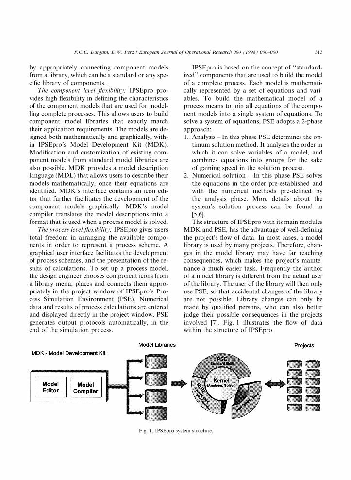
MDK and PSE, has the advantage of well-de®ningthe project's ¯ow of data. In most cases, a modellibrary is used by many projects. Therefore, chan-ges in the model library may have far reachingconsequences, which makes the project's mainte-nance a much easier task. Frequently the authorof a model library is di�erent from the actual userof the library. The user of the library will then onlyuse PSE, so that accidental changes of the libraryare not possible. Library changes can only bemade by quali®ed persons, who can also betterjudge their possible consequences in the projectsinvolved [7]. Fig. 1 illustrates the ¯ow of datawithin the structure of IPSEpro.
Fig. 1. IPSEpro system structure.
F.C.C. Dargam, E.W. Perz / European Journal of Operational Research 000 (1998) 000±000 313
The standard libraries currently available forIPSEpro are: the APP-Lib for power plant simula-tions; the gas-turbines library; and the heat-ex-changers library. The advanced power plantlibrary was designed for modelling a wide rangeof thermal systems. This library contains modelsfor both design and o�-design analysis of anypower plant, including: combined-cycle plants; co-generation plants; and conventional plants. Thegas-turbines library was designed to be used inconjunction with the APP-Lib for the design ofpower plants. It contains models of the most usedgas turbines of several di�erent manufacturers.The heat-exchangers library provides models fordetailed calculation of heat exchangers [8].
IPSEpro was designed as a Microsoft Windowsapplication, and it fully supports Windows 95 andNT.
4.2. How the DSS module integrates with IPSEpro
The design support system will cooperate withthe IPSEpro process simulation environmentPSE, for setting up a process scheme and for opti-mizing the ®nal project. In the speci®c case of thepower plant design support system module, namedIPSEpro-PP-DSS, the integration also involves themodel libraries of gas-turbines (GT-Lib) and ad-vanced power plant (APP-Lib). Basically, theIPSEpro-PP-DSS can be activated whenever a de-sign engineer, using PSE in conjunction with the li-braries APP-Lib + GT-Lib, requests for designsupport. The support is given within the levels al-ready mentioned: the plant modelling level, andthe innovative solutions level.
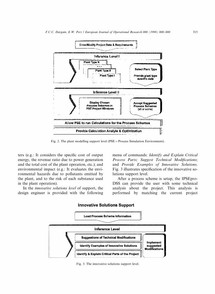
Within the plant modelling level of support, thedesign engineer is provided with the followingmenu of commands: Enter and Modify Project Da-ta; Choose Type(s) of Plant(s); Choose RequiredModel(s); Accept Suggested Solution(s); PerformCalculation Error Analysis; Perform QualitativeAnalysis; and Suggest Structural Optimization.These commands activate some DSS's tasks, whichinteract with the system's knowledge base in orderto provide the appropriate suggestions. The sug-gestions are based on recommended choices, suchas types of plants according to the initial project
data; and required component models accordingto the type of plant, etc. Fig. 2 illustrates the spec-i®cation of the plant modelling support level.
Initially, the design support system requests theuser some minimum required data about the pro-ject's technical and legal constraints. This informa-tion concerns, for instance, the input fuel used,approximate values of the electric output of thepower plant, of the amount of process steam, min-imum exhaust gas temperature, etc. Based on thispreliminary data, the system is able to infer thepossible types of plants that can be built (e.g.:combined-cycle plant, cogeneration plant, conven-tional plant, etc.), and the possible required com-ponent models (e.g.: turbines, heat-exchangers,pumps, boilers, etc.) for each plant type. The de-sign engineer is prompted with sets of suggestions,that should be selected to generate process schemesfor further calculations in IPSEpro-PSE. One ormore types of plants can be chosen by the user.This implies that the IPSEpro-DSS should providesupport for parallel alternative solutions of theproject.
The process schemes of power plants suggestedby the design support system will serve as a start-up for the actual project. It is then up to the designengineer to make the appropriate add-ons in termsof components and their connections, as well as tomodify the initial model parameters, before run-ning the simulation of the plant.
After a ®rst run of the PSE simulation, theremay be some indications of errors which are usual,specially in initial projects set-ups. The design sup-port system is able to analyse the PSE simulationerrors and explain their nature to the design engi-neer, so that they can easily ®x the problems beforetrying the simulation again. Another support of thesystem concerns the suggestion of structural opti-mization of the ®nal process scheme, if necessary.
The qualitative analysis of the project takes intoaccount the plant structural con®guration and op-eration conditions. To make this analysis, the sys-tem uses its knowledge about reliability and safetyin operation and energy supply (e.g.: It measuresthe ratio of unplanned outage service time of theplant, evaluates the forced load reductions consid-ering the energy that the plant can produce and theactually produced energy, etc.); economic parame-
314 F.C.C. Dargam, E.W. Perz / European Journal of Operational Research 109 (1998) 310±320
ters (e.g.: It considers the speci®c cost of outputenergy, the revenue ratio due to power generationand the total cost of the plant operation, etc.); andenvironmental impact (e.g.: It evaluates the envi-ronmental hazards due to pollutants emitted bythe plant, and to the risk of each substance usedin the plant operation).
In the innovative solutions level of support, thedesign engineer is provided with the following
menu of commands: Identify and Explain CriticalProcess Parts; Suggest Technical Modi®cations;and Provide Examples of Innovative Solutions.Fig. 3 illustrates speci®cation of the innovative so-lutions support level.
After a process scheme is setup, the IPSEpro-DSS can provide the user with some technicalanalysis about the project. This analysis isperformed by matching the current project
Fig. 3. The innovative solutions support level.
Fig. 2. The plant modelling support level (PSE�Process Simulation Environment).
F.C.C. Dargam, E.W. Perz / European Journal of Operational Research 000 (1998) 000±000 315
description available in the project database,against some pre-de®ned critical process models,which are stored in the system's model base.Whenever a critical part of the current project isidenti®ed, it is graphically highlighted and the ex-planation of its technical critical nature is given.At this point, the design engineer can request theDSS for project modi®cation suggestions, basedon the identi®ed problems. Another possibility,at this stage, is that the system supplies the designengineer with some examples of innovative solu-tions which may apply to the current project.The solutions suggested by the system are derivedfrom an inference process, which takes into ac-count the current process scheme and its criticalparts; and the encoded knowledge of possible com-binations of plant components, e�cient processschemes for the chosen plant type, and existingsuccessful innovations in the area. The adoptionand adaptation of those innovative solutions intothe current process scheme is completely up tothe designer.
5. The IPSEpro-DSS structure
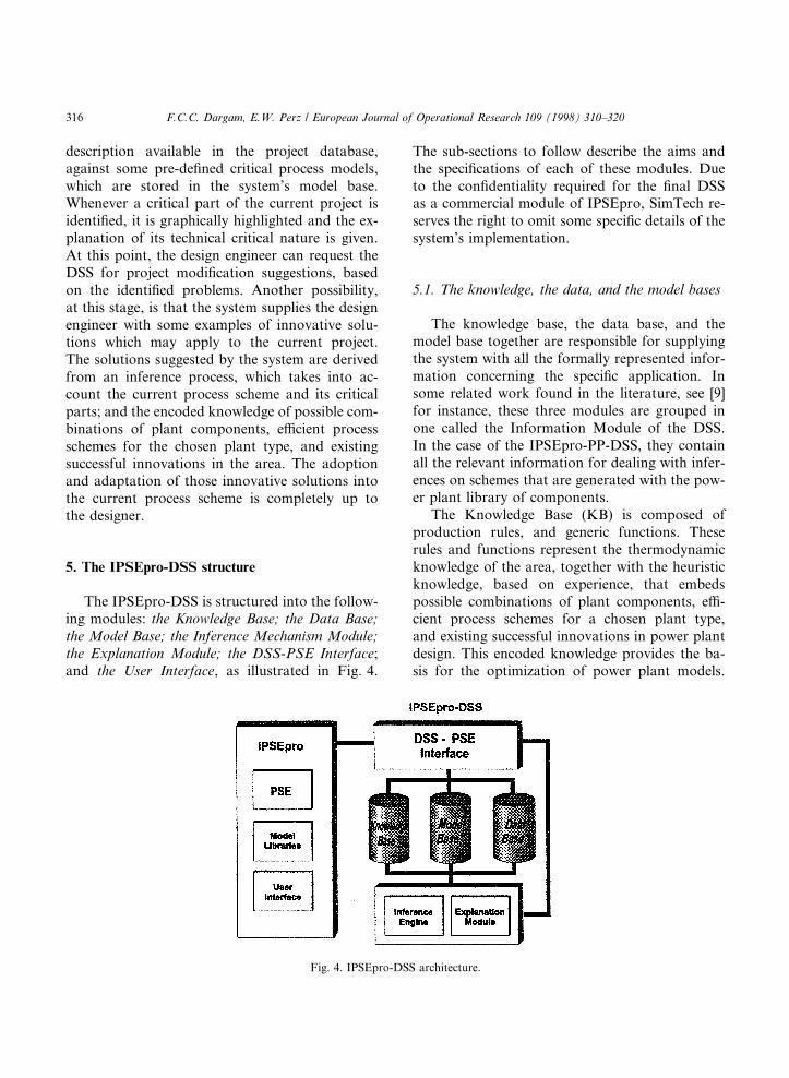
The IPSEpro-DSS is structured into the follow-ing modules: the Knowledge Base; the Data Base;the Model Base; the Inference Mechanism Module;the Explanation Module; the DSS-PSE Interface;and the User Interface, as illustrated in Fig. 4.
The sub-sections to follow describe the aims andthe speci®cations of each of these modules. Dueto the con®dentiality required for the ®nal DSSas a commercial module of IPSEpro, SimTech re-serves the right to omit some speci®c details of thesystem's implementation.
5.1. The knowledge, the data, and the model bases
The knowledge base, the data base, and themodel base together are responsible for supplyingthe system with all the formally represented infor-mation concerning the speci®c application. Insome related work found in the literature, see [9]for instance, these three modules are grouped inone called the Information Module of the DSS.In the case of the IPSEpro-PP-DSS, they containall the relevant information for dealing with infer-ences on schemes that are generated with the pow-er plant library of components.
The Knowledge Base (KB) is composed ofproduction rules, and generic functions. Theserules and functions represent the thermodynamicknowledge of the area, together with the heuristicknowledge, based on experience, that embedspossible combinations of plant components, e�-cient process schemes for a chosen plant type,and existing successful innovations in power plantdesign. This encoded knowledge provides the ba-sis for the optimization of power plant models.
Fig. 4. IPSEpro-DSS architecture.
316 F.C.C. Dargam, E.W. Perz / European Journal of Operational Research 109 (1998) 310±320
Logically, we can view the knowledge base ofIPSEpro-PP-DSS as divided into three sub-bases:KB-TD; KB-PM; and KB-IS. KB-TD is responsi-ble for the thermodynamic knowledge. KB-PMcaters for the process model knowledge, includingpossible plant types, combinations of plant com-ponents, and e�cient process schemes. It alsocontains the project's operation constraints forthe processing of the qualitative analysis and ofstructural optimizations. KB-IS encodes theknowledge about the successful innovative solu-tions in power plant design.
The development tool chosen to build and tomanipulate the KB is called CLIPS (C LanguageIntegrated Production System) [10]. CLIPS sup-ports knowledge representation, portability, inte-gration/extensibility, interactive development, andobjects (a concept from object-oriented program-ming). It provides a complete environment forthe construction of rules and/or object based ex-pert systems, including a veri®cation/validationutility. In [11], session 2B, we ®nd interesting ap-plications of decision making systems usingCLIPS, like: ``Decision Blocks: A tool for Auto-mating Decision Making in CLIPS'', and``ICADS: A Cooperative Decision Making Modelwith CLIPS Experts''.
One of our main motivations in choosingCLIPS for building IPSEpro-DSS, was its highlevel of integration capability. CLIPS can becalled from another program, perform its func-tion, and then return the control to the main call-ing program. This feature was a fundamentalrequirement for integrating IPSEpro-DSS withIPSEpro-PSE.
The Data Base (DB) works as the projectdata memory, containing component parame-ters, lay-out description, and lists of facts andinstances that currently represent the powerplant project under consideration. This moduleis continuously updated in relation to the infor-mation of the PSE process model that is undersupport.
The Model Base (MB) contains encoded de-scriptions of some pre-de®ned critical and innova-tive process models; and the algorithms which areused for the generation, and evaluation of suggest-ed process schemes.
5.2. The inference mechanism
The inference mechanism module is responsiblefor the problem solution process, and re¯ects thedecisions supported by the system. This modulehandles information from and to the informationbases described above, and controls overall execu-tion of rules from the KB. The knowledge and thedata bases supply the inference mechanism withthe available data, so that the appropriate re-commendations are given. Rules from KB are®red, driven by the factual data of DB. In IPSE-pro-DSS, the CLIPS production rules forward-chaining inference mechanism is used, with sevendi�erent strategies of con¯ict resolution: depth;breadth; LEX; MEA; complexity; simplicity; andrandom [12]. The model base MB processes the re-sulting inferences into possible alternatives of fea-sible process schemes.
5.3. The explanation module
The explanation module, as the name indi-cates, is responsible for explaining to the userthe basis of the system's decisions and sugges-tions. It is directly linked to the inference engine,and to the knowledge and model bases. It alsoreceives, via the data base, the information thatre¯ects the process model of the PSE project un-der support.
So far, the system is only speci®ed to explainsimulation error analysis, the results of the pro-ject's qualitative analysis, and some critical designstructures for power plant models. These explana-tions are given whenever the user selects the com-mands: Perform Calculation Error Analysis;Perform Qualitative Analysis; and Identify and Ex-plain Critical Process Parts, respectively. It is ourgoal, however, to allow IPSEpro-DSS also to pro-vide \what-if" answers during arbitrary phases ofthe power plant design.
5.4. The DSS-PSE interface
The DSS-PSE interface is responsible for theproper communication between the design support
F.C.C. Dargam, E.W. Perz / European Journal of Operational Research 000 (1998) 000±000 317
module and other modules in the IPSEpro envi-ronment like: PSE and the libraries. This interfaceis transparent to the user. It works in di�erentphases of the design support system. It enablesthe IPSEpro-DSS to show the results of suggestedprocess schemes in PSE project windows. It alsoallows the system to identify, within an existingPSE process model, critical technical points, aswell as calculation errors for generating explana-tion analysis. The DSS-PSE Interface also pro-vides links with the CLIPS environment. It iscomposed of a bi-directional interpreter, whichcan generate process schemes graphically for thePSE Windows interface. Likewise, it can also un-derstand the graphics of a process scheme for fur-ther processing by the model base or by theinference engine, using information stored in KBand in DB.
5.5. The user interface
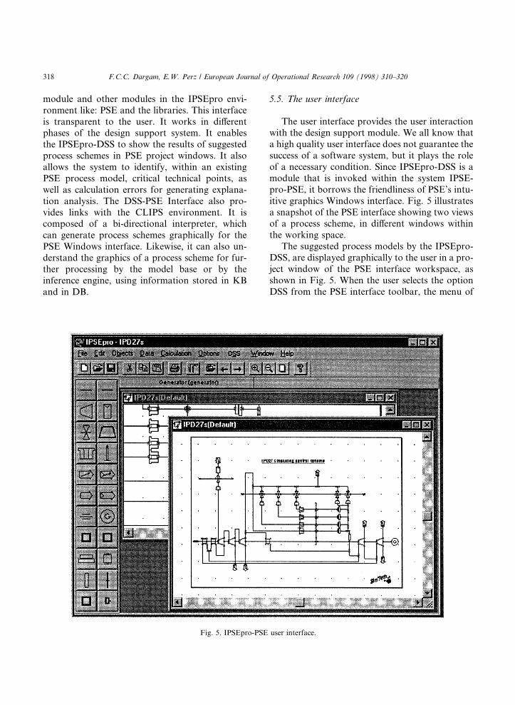
The user interface provides the user interactionwith the design support module. We all know thata high quality user interface does not guarantee thesuccess of a software system, but it plays the roleof a necessary condition. Since IPSEpro-DSS is amodule that is invoked within the system IPSE-pro-PSE, it borrows the friendliness of PSE's intu-itive graphics Windows interface. Fig. 5 illustratesa snapshot of the PSE interface showing two viewsof a process scheme, in di�erent windows withinthe working space.
The suggested process models by the IPSEpro-DSS, are displayed graphically to the user in a pro-ject window of the PSE interface workspace, asshown in Fig. 5. When the user selects the optionDSS from the PSE interface toolbar, the menu of
Fig. 5. IPSEpro-PSE user interface.
318 F.C.C. Dargam, E.W. Perz / European Journal of Operational Research 109 (1998) 310±320
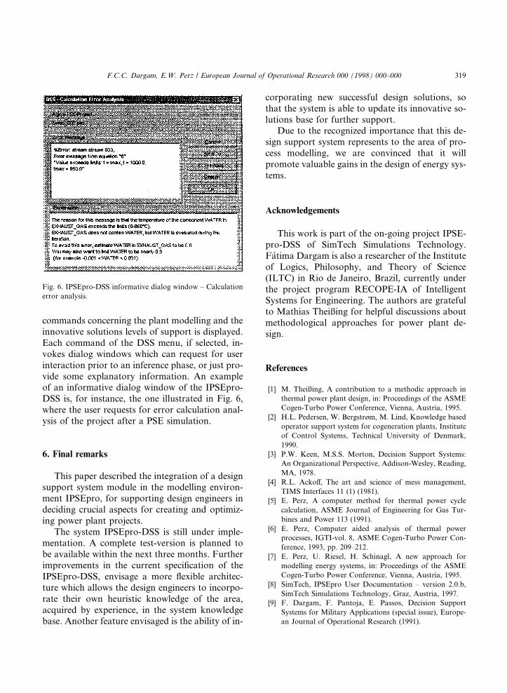
commands concerning the plant modelling and theinnovative solutions levels of support is displayed.Each command of the DSS menu, if selected, in-vokes dialog windows which can request for userinteraction prior to an inference phase, or just pro-vide some explanatory information. An exampleof an informative dialog window of the IPSEpro-DSS is, for instance, the one illustrated in Fig. 6,where the user requests for error calculation anal-ysis of the project after a PSE simulation.
6. Final remarks
This paper described the integration of a designsupport system module in the modelling environ-ment IPSEpro, for supporting design engineers indeciding crucial aspects for creating and optimiz-ing power plant projects.
The system IPSEpro-DSS is still under imple-mentation. A complete test-version is planned tobe available within the next three months. Furtherimprovements in the current speci®cation of theIPSEpro-DSS, envisage a more ¯exible architec-ture which allows the design engineers to incorpo-rate their own heuristic knowledge of the area,acquired by experience, in the system knowledgebase. Another feature envisaged is the ability of in-
corporating new successful design solutions, sothat the system is able to update its innovative so-lutions base for further support.
Due to the recognized importance that this de-sign support system represents to the area of pro-cess modelling, we are convinced that it willpromote valuable gains in the design of energy sys-tems.
Acknowledgements
This work is part of the on-going project IPSE-pro-DSS of SimTech Simulations Technology.F�atima Dargam is also a researcher of the Instituteof Logics, Philosophy, and Theory of Science(ILTC) in Rio de Janeiro, Brazil, currently underthe project program RECOPE-IA of IntelligentSystems for Engineering. The authors are gratefulto Mathias Theiûing for helpful discussions aboutmethodological approaches for power plant de-sign.
References
[1] M. Theiûing, A contribution to a methodic approach in
thermal power plant design, in: Proceedings of the ASME
Cogen-Turbo Power Conference, Vienna, Austria, 1995.
[2] H.L. Pedersen, W. Bergstrùm, M. Lind, Knowledge based
operator support system for cogeneration plants, Institute
of Control Systems, Technical University of Denmark,
1990.
[3] P.W. Keen, M.S.S. Morton, Decision Support Systems:
An Organizational Perspective, Addison-Wesley, Reading,
MA, 1978.
[4] R.L. Acko�, The art and science of mess management,
TIMS Interfaces 11 (1) (1981).
[5] E. Perz, A computer method for thermal power cycle
calculation, ASME Journal of Engineering for Gas Tur-
bines and Power 113 (1991).
[6] E. Perz, Computer aided analysis of thermal power
processes, IGTI-vol. 8, ASME Cogen-Turbo Power Con-
ference, 1993, pp. 209±212.
[7] E. Perz, U. Riesel, H. Schinagl, A new approach for
modelling energy systems, in: Proceedings of the ASME
Cogen-Turbo Power Conference, Vienna, Austria, 1995.
[8] SimTech, IPSEpro User Documentation ± version 2.0.b,
SimTech Simulations Technology, Graz, Austria, 1997.
[9] F. Dargam, F. Pantoja, E. Passos, Decision Support
Systems for Military Applications (special issue), Europe-
an Journal of Operational Research (1991).
Fig. 6. IPSEpro-DSS informative dialog window ± Calculation
error analysis.
F.C.C. Dargam, E.W. Perz / European Journal of Operational Research 000 (1998) 000±000 319

[10] J. Giarratano, CLIPS User Guide ± version 6.0, Software
Technology Branch, NASA/Lyndon B. Johnson Space
Center, 1993.
[11] NASA/JSC., Proceedings of the Second CLIPS Users
Conference, NASA/Johnson Space Center, NASA Con-
ference Publication 10085, 1991.
[12] G. Riley, CLIPS: An expert system building tool, in:
Proceedings of the Technology 2001 Conference, San Jose,
CA, 1991.
320 F.C.C. Dargam, E.W. Perz / European Journal of Operational Research 109 (1998) 310±320
Recommended