Online at www.worldautosteel.org Copyright© International Iron & Steel Institute
ADVANCED HIGH STRENGTH STEEL (AHSS)APPLICATION GUIDELINES
Prepared by
INTERNATIONAL IRON & STEEL INSTITUTECommittee on Automotive Applications
March 2005
AD
VA
NC
ED
HIG
H S
TR
EN
GT
H S
TE
EL A
PP
LICA
TIO
N G
UID
ELIN
ES
Online at www.worldautosteel.org
Revised: 18 Mar 2005
Page ii
Table of ContentsPreface ..................................................................................................................... iiiExecutive Overview .................................................................................................. vSection 1 - General Description of AHSS ............................................................... 1-1
1a - Definitions ............................................................................................ 1-11b - Metallurgy of AHSS ............................................................................. 1-3
Dual Phase (DP) Steel ................................................................... 1-3Transformation-Induced Plasticity (TRIP) Steel............................ 1-4Complex Phase (CP) Steel ............................................................ 1-5Martensitic (Mart) Steel .................................................................. 1-5AHSS Processing........................................................................... 1-6
1c - Common Steel Types and Evolving AHSS Types ............................... 1-7Common Steel Types ..................................................................... 1-7Evolving AHSS Types .................................................................... 1-8
Section 2 - Forming .................................................................................................. 2-12a - General Comments.............................................................................. 2-12b - Computerized Forming-Process Development .................................. 2-22c - Sheet Forming ..................................................................................... 2-4
Mechanical Properties ................................................................... 2-4Forming Limits ................................................................................ 2-12Forming Modes .............................................................................. 2-18Tool Design .................................................................................... 2-24Springback ..................................................................................... 2-29Blanking, Shearing, and Trim Operations ..................................... 2-48Press Requirements ...................................................................... 2-49Multiple Stage Forming .................................................................. 2-56In-service Requirements ................................................................ 2-58
2d - Tube Forming....................................................................................... 2-61High Frequency Welded Tubes ..................................................... 2-61Laser Welded Tailored Tubes ....................................................... 2-65
Section 3 - Joining.................................................................................................... 3-13a - General Comments.............................................................................. 3-13b - Welding Procedures ............................................................................ 3-2
Resistance Welding ....................................................................... 3-2High Frequency Induction Welding ............................................... 3-8Laser Welding - Fusion ................................................................. 3-10Arc Welding – Fusion .................................................................... 3-12Weld Integrity: Test Method and Joint Performance..................... 3-14
3c - Brazing ................................................................................................. 3-183d - Adhesive Bonding ................................................................................ 3-193e - Mechanical Joining .............................................................................. 3-203f - Hybrid Joining ....................................................................................... 3-223g - Material Issues For Weld Repair ........................................................ 3-23
Section 4 – Glossary ................................................................................................ 4-1Section 5 – References ............................................................................................ 5-1
AD
VA
NC
ED
HIG
H S
TR
EN
GT
H S
TE
EL A
PP
LICA
TIO
N G
UID
ELIN
ES
Online at www.worldautosteel.org
Revised: 18 Mar 2005
Page iii
PrefaceRecent years have seen many new developments in steel technology and manufacturing processesto build vehicles of reduced mass and increased safety with steel. The ULSAB (UltraLight SteelAuto Body) and ULSAB-AVC (Advanced Vehicle Concepts) programmes, sponsored by the globalsteel industry, focused attention on advances in lightweight design concepts and on more extensiveuse of Advanced High-Strength Steel (AHSS) – a key enabling factor in lightweight design. Alongwith the advantages of these newer steels came the need to provide technical advice for formingand joining techniques.
AHSS Application Guidelines described in this document are the result of a cooperative effort byexperts from steel company members of the International Iron and Steel Institute (IISI). We gratefullyacknowledge the input of many people around the world – in particular, those listed here whowere the core working group:
Dr Heiko Beenken ThyssenKrupp StahlMr Willie Bernert DofascoMr Klaus Blümel ThyssenKrupp StahlDr Björn Carlsson SSAB TunnplåtDr Jayanth Chintamani Mittal SteelMr Dominique Fouques ArcelorMr Makoto Imanaka JFE HoldingsDr Andre Kröff Salzgitter Mannesmann ForschungDr Sree Harsha Lalam Mittal SteelMr Andy Lee DofascoMr Tony Nilsson SSAB TunnplåtMr Juha Nuutinen Rautaruukki OyjMr Chuck Potter American Iron and Steel InstituteMr Wilfried Prange ThyssenKrupp StahlMr Pekka Ritakallio Rautaruukki OyjDr Ming Shi United States Steel CorporationDr Jan-Olof Sperle SSAB TunnplåtMr John Szalla BlueScope SteelMr Johann Szinyur voestalpine StahlMr Andy Taylor CorusMr Christian Walch voestalpine StahlDr Kazumasa Yamazaki Nippon Steel Corporation
A special note of appreciation goes to Dr Stuart Keeler of Keeler Technologies LLC who servedas Technical Editor. Dr Keeler is a widely known expert, author and lecturer in the field of metalforming and application. He provided valuable input and coordination of the complete AHSSApplication Guidelines document.
These Guidelines and other IISI information can be found at www.worldautosteel.org. IISI steelcompanies who sponsor this work are listed on the next page.
Edward G. OpbroekDirector, AutomotiveInternational Iron and Steel Institute
AD
VA
NC
ED
HIG
H S
TR
EN
GT
H S
TE
EL A
PP
LICA
TIO
N G
UID
ELIN
ES
Online at www.worldautosteel.org
PREFACE
Page iv
Company members of the International Iron and Steel Institute (IISI) who work through theCommittee on Automotive Applications (AutoCo) to sponsor this work are as follows:
IISI-AUTOCO COMPANY MEMBERS
Arcelor - Luxembourg
BlueScope Steel- Australia
China Steel Corporation - Taiwan, China
Corus Group - UK & Netherlands
Dofasco Inc. - Canada
Mittal Steel - South Africa
Mittal Steel - USA
JFE Steel Corporation - Japan
Kobe Steel, Ltd.. - Japan
Nippon Steel Corporation - Japan
POSCO - South Korea
Rautaruukki Oyj - Finland
Salzgitter AG - Germany
Severstal N.A. - United States
SSAB Tunnplåt AB - Sweden
Sumitomo Metal Industries, Ltd. - Japan
ThyssenKrupp Stahl AG - Germany
United States Steel Corporation - USA
Usinas Siderúrgicas de Minas Gerais S.A. (USIMINAS) - Brazil
voestalpine Stahl GmbH - Austria
AD
VA
NC
ED
HIG
H S
TR
EN
GT
H S
TE
EL A
PP
LICA
TIO
N G
UID
ELIN
ES
Online at www.worldautosteel.org
Revised: 18 Mar 2005
Page v
Executive Overview
Automotive customers are asking for more steel options to meet increased specifications forstrength, crash worthiness, energy absorption, part complexity, and dent resistance. To meetthese requirements, the international steel community has developed new types of steel knownas Advanced High-Strength Steels (AHSS). Application guidelines for these steels are containedin this document.
Within AHSS two distinct families of steel types are available. The first is the high-strength steelswith increased formability for more complex part designs. These are dual phase (DP) andtransformation induced plasticity (TRIP) steels. The second family has increased tensile strengthwhile maintaining good crush resistance and energy absorption. These are complex phase (CP)and martensitic (Mart) steels.
The Application Guidelines document, drafted by experts from the International Iron and SteelInstitute, has three major sections. The first section contains terminology and descriptions of themicrostructures that create the unique combination of properties. To circumvent regional differencesin grade designation, the document utilizes a more detailed description of each grade. For example,DP 350/600 is a dual phase steel with minimum yield strength of 350 MPa and minimum tensilestrength of 600 MPa.
The second section – Forming – includes mechanical properties, forming limits, forming modes,springback, press loads, blanking, and other key formability issues to assist in the proper applicationof AHSS. Here AHSS are compared to the more familiar conventional higher strength steels incommon use. Major emphasis is placed on springback control and compensation necessitatedby the differences in work hardening and stress – strain curves of AHSS.
The third section – Joining – illustrates that AHSS are satisfactorily weldable for automotiveapplications. However, the as-received microstructure will be changed while welding AHSS.Therefore some precautions have to be taken during welding for successful AHSS welded joints.Subtopics presented are welding processes, brazing, mechanical joining, hybrid joining, andweld repair.
The AHSS Application Guidelines document is available for download on www.worldautosteel.org/ AHSS Guidelines or by contacting one of the steel company members of the International Ironand Steel Institute AutoCo Group listed on www.worldautosteel.org / IISI AutoCo membercompanies.
AD
VA
NC
ED
HIG
H S
TR
EN
GT
H S
TE
EL A
PP
LICA
TIO
N G
UID
ELIN
ES
Online at www.worldautosteel.org
Revised: 12 May 2005
Page 1-1
Section 1 - General Description of AHSSThe Advanced High-Strength Steel (AHSS) Application Guidelines focus on press-forming andfabrication processes for automotive underbody, structural, and body panels designed for higherstrength steels. When selecting conventional high-strength steels to replace mild steel or othertraditional grades, reduced formability is often one of the unwelcome consequences. To overcomethis, and to further achieve lower mass automotive structures, recent steel developments havetargeted improvements in formability. The AHSS family of multi-phase microstructures typifies thesteel industry’s response to the demand for improved materials that utilize proven productionmethods. These engineered materials address the automotive industry’s need for steels withboth higher strength and enhanced formability.
1a - Definitions
Automotive steels can be defined in several different ways. The first is by metallurgical designation.Common descriptions include low-strength steels (interstitial-free and mild steels); conventionalhigh-strength steels (carbon-manganese, bake hardenable, isotropic, high-strength IF, and high-strength, low-alloy steels); and the newer types of advanced high-strength steels (dual phase,transformation induced plasticity, complex phase, and martensitic steels).
The second classification method is based on one of the mechanical properties - strength. High-Strength Steels (HSS) are defined as those steels with tensile strengths from 270–700 MPa. Ultra-High-Strength Steels (UHSS) are defined as steels with tensile strengths greater than 700 MPa.
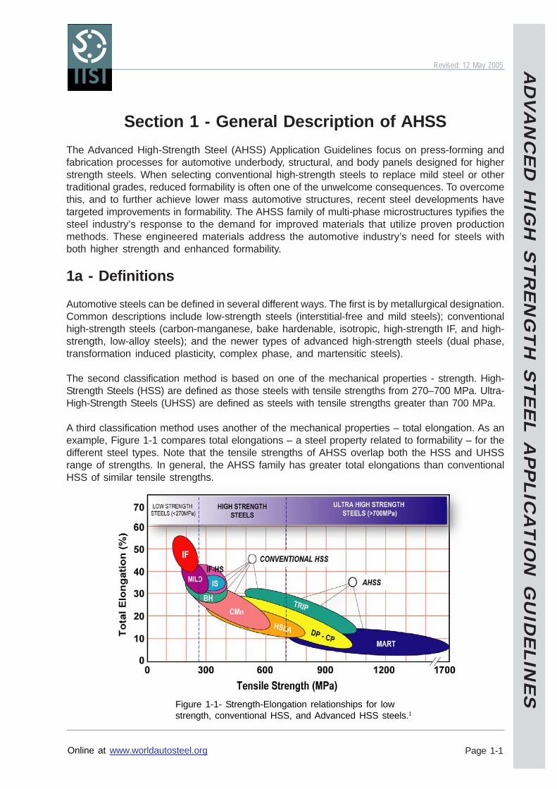
A third classification method uses another of the mechanical properties – total elongation. As anexample, Figure 1-1 compares total elongations – a steel property related to formability – for thedifferent steel types. Note that the tensile strengths of AHSS overlap both the HSS and UHSSrange of strengths. In general, the AHSS family has greater total elongations than conventionalHSS of similar tensile strengths.
Figure 1-1- Strength-Elongation relationships for lowstrength, conventional HSS, and Advanced HSS steels.1
AD
VA
NC
ED
HIG
H S
TR
EN
GT
H S
TE
EL A
PP
LICA
TIO
N G
UID
ELIN
ES
Online at www.worldautosteel.org
SECTION 1 - GENERAL DESCRIPTION OF AHSS
Page 1-2
1a - DEFINITIONS
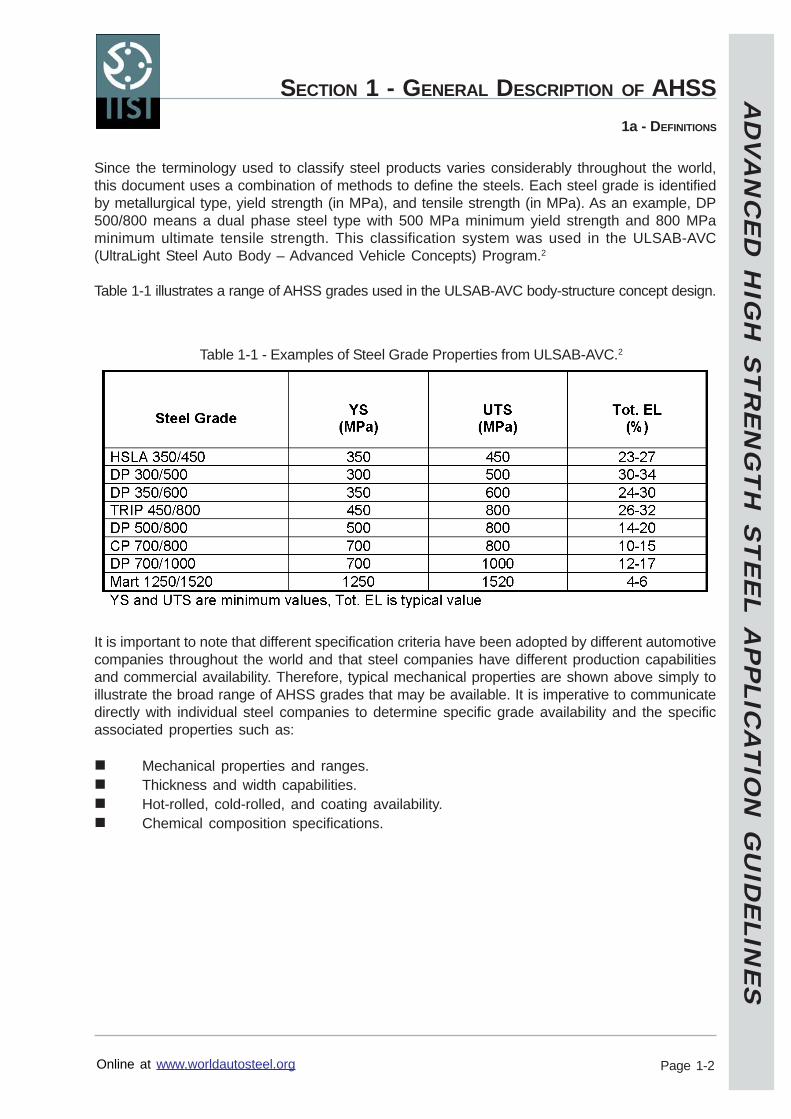
Since the terminology used to classify steel products varies considerably throughout the world,this document uses a combination of methods to define the steels. Each steel grade is identifiedby metallurgical type, yield strength (in MPa), and tensile strength (in MPa). As an example, DP500/800 means a dual phase steel type with 500 MPa minimum yield strength and 800 MPaminimum ultimate tensile strength. This classification system was used in the ULSAB-AVC(UltraLight Steel Auto Body – Advanced Vehicle Concepts) Program.2
Table 1-1 illustrates a range of AHSS grades used in the ULSAB-AVC body-structure concept design.
It is important to note that different specification criteria have been adopted by different automotivecompanies throughout the world and that steel companies have different production capabilitiesand commercial availability. Therefore, typical mechanical properties are shown above simply toillustrate the broad range of AHSS grades that may be available. It is imperative to communicatedirectly with individual steel companies to determine specific grade availability and the specificassociated properties such as:
Mechanical properties and ranges.Thickness and width capabilities.Hot-rolled, cold-rolled, and coating availability.Chemical composition specifications.
Table 1-1 - Examples of Steel Grade Properties from ULSAB-AVC.2
AD
VA
NC
ED
HIG
H S
TR
EN
GT
H S
TE
EL A
PP
LICA
TIO
N G
UID
ELIN
ES
Online at www.worldautosteel.org
SECTION 1 - GENERAL DESCRIPTION OF AHSS
Page 1-3
1b - METALLURGY OF AHSS
1b - Metallurgy of AHSS
The fundamental metallurgy of conventional low- and high-strength steels is generally wellunderstood by manufacturers and users of steel products. Since the metallurgy and processingof AHSS grades are somewhat novel compared to conventional steels, they will be describedhere to provide a baseline understanding of how their remarkable mechanical properties evolvefrom their unique processing and structure. Brief descriptions of common steel types are given inSection 1c.
Dual Phase (DP) Steel
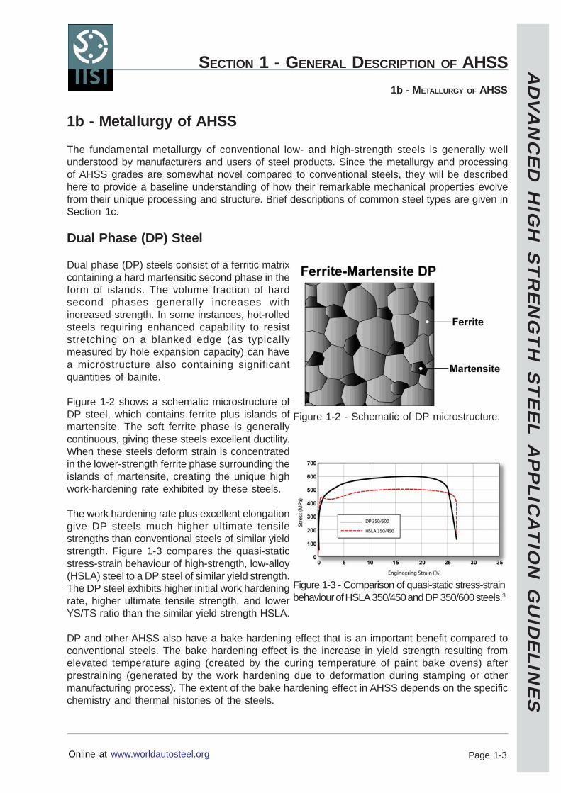
Dual phase (DP) steels consist of a ferritic matrixcontaining a hard martensitic second phase in theform of islands. The volume fraction of hardsecond phases generally increases withincreased strength. In some instances, hot-rolledsteels requiring enhanced capability to resiststretching on a blanked edge (as typicallymeasured by hole expansion capacity) can havea microstructure also containing significantquantities of bainite.
Figure 1-2 shows a schematic microstructure ofDP steel, which contains ferrite plus islands ofmartensite. The soft ferrite phase is generallycontinuous, giving these steels excellent ductility.When these steels deform strain is concentratedin the lower-strength ferrite phase surrounding theislands of martensite, creating the unique highwork-hardening rate exhibited by these steels.
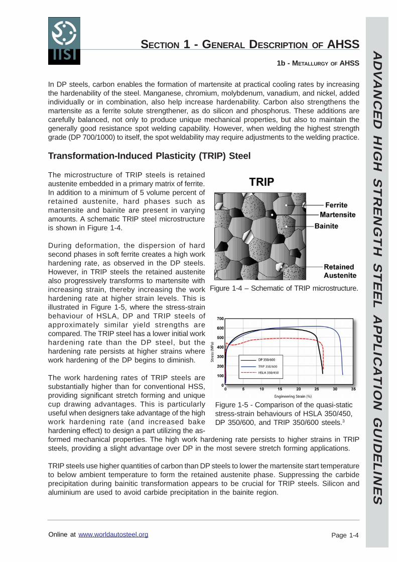
The work hardening rate plus excellent elongationgive DP steels much higher ultimate tensilestrengths than conventional steels of similar yieldstrength. Figure 1-3 compares the quasi-staticstress-strain behaviour of high-strength, low-alloy(HSLA) steel to a DP steel of similar yield strength.The DP steel exhibits higher initial work hardeningrate, higher ultimate tensile strength, and lowerYS/TS ratio than the similar yield strength HSLA.
DP and other AHSS also have a bake hardening effect that is an important benefit compared toconventional steels. The bake hardening effect is the increase in yield strength resulting fromelevated temperature aging (created by the curing temperature of paint bake ovens) afterprestraining (generated by the work hardening due to deformation during stamping or othermanufacturing process). The extent of the bake hardening effect in AHSS depends on the specificchemistry and thermal histories of the steels.
Figure 1-2 - Schematic of DP microstructure.
Figure 1-3 - Comparison of quasi-static stress-strainbehaviour of HSLA 350/450 and DP 350/600 steels.3
AD
VA
NC
ED
HIG
H S
TR
EN
GT
H S
TE
EL A
PP
LICA
TIO
N G
UID
ELIN
ES
Online at www.worldautosteel.org
SECTION 1 - GENERAL DESCRIPTION OF AHSS
Page 1-4
1b - METALLURGY OF AHSS
In DP steels, carbon enables the formation of martensite at practical cooling rates by increasingthe hardenability of the steel. Manganese, chromium, molybdenum, vanadium, and nickel, addedindividually or in combination, also help increase hardenability. Carbon also strengthens themartensite as a ferrite solute strengthener, as do silicon and phosphorus. These additions arecarefully balanced, not only to produce unique mechanical properties, but also to maintain thegenerally good resistance spot welding capability. However, when welding the highest strengthgrade (DP 700/1000) to itself, the spot weldability may require adjustments to the welding practice.
Transformation-Induced Plasticity (TRIP) Steel
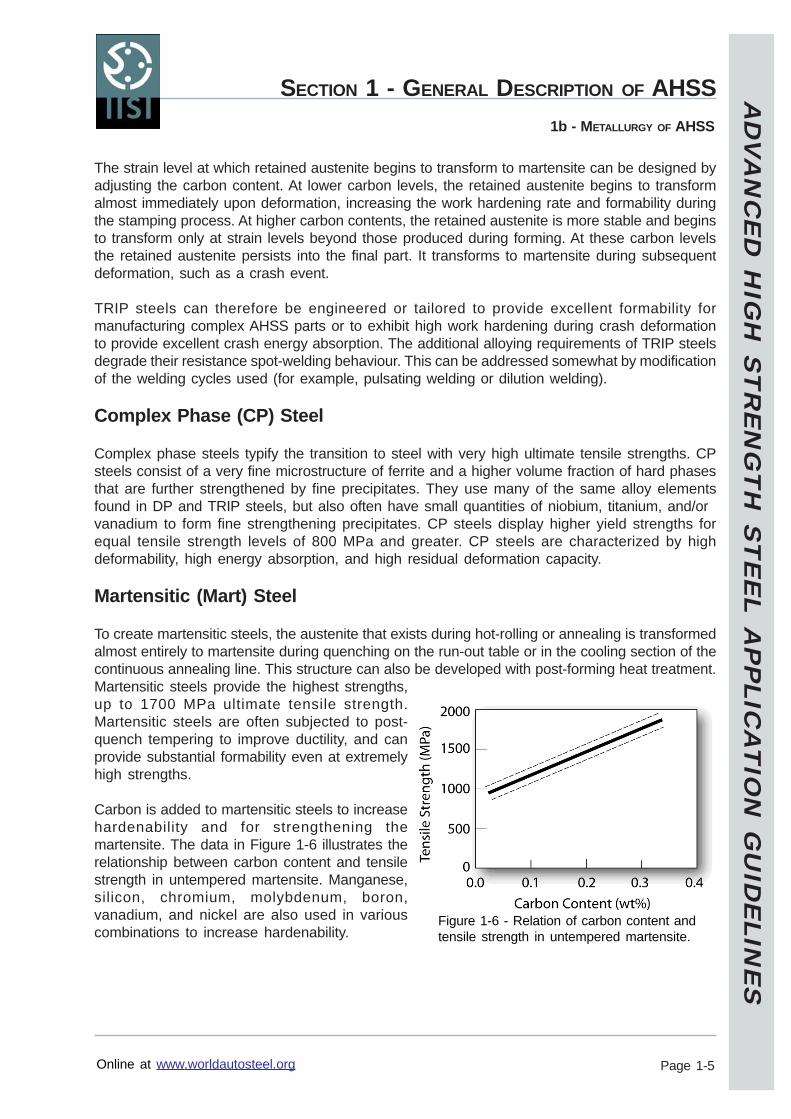
The microstructure of TRIP steels is retainedaustenite embedded in a primary matrix of ferrite.In addition to a minimum of 5 volume percent ofretained austenite, hard phases such asmartensite and bainite are present in varyingamounts. A schematic TRIP steel microstructureis shown in Figure 1-4.
During deformation, the dispersion of hardsecond phases in soft ferrite creates a high workhardening rate, as observed in the DP steels.However, in TRIP steels the retained austenitealso progressively transforms to martensite withincreasing strain, thereby increasing the workhardening rate at higher strain levels. This isillustrated in Figure 1-5, where the stress-strainbehaviour of HSLA, DP and TRIP steels ofapproximately similar yield strengths arecompared. The TRIP steel has a lower initial workhardening rate than the DP steel, but thehardening rate persists at higher strains wherework hardening of the DP begins to diminish.
The work hardening rates of TRIP steels aresubstantially higher than for conventional HSS,providing significant stretch forming and uniquecup drawing advantages. This is particularlyuseful when designers take advantage of the highwork hardening rate (and increased bakehardening effect) to design a part utilizing the as-formed mechanical properties. The high work hardening rate persists to higher strains in TRIPsteels, providing a slight advantage over DP in the most severe stretch forming applications.
TRIP steels use higher quantities of carbon than DP steels to lower the martensite start temperatureto below ambient temperature to form the retained austenite phase. Suppressing the carbideprecipitation during bainitic transformation appears to be crucial for TRIP steels. Silicon andaluminium are used to avoid carbide precipitation in the bainite region.
Figure 1-4 – Schematic of TRIP microstructure.
Figure 1-5 - Comparison of the quasi-staticstress-strain behaviours of HSLA 350/450,DP 350/600, and TRIP 350/600 steels.3
AD
VA
NC
ED
HIG
H S
TR
EN
GT
H S
TE
EL A
PP
LICA
TIO
N G
UID
ELIN
ES
Online at www.worldautosteel.org
SECTION 1 - GENERAL DESCRIPTION OF AHSS
Page 1-5
1b - METALLURGY OF AHSS
The strain level at which retained austenite begins to transform to martensite can be designed byadjusting the carbon content. At lower carbon levels, the retained austenite begins to transformalmost immediately upon deformation, increasing the work hardening rate and formability duringthe stamping process. At higher carbon contents, the retained austenite is more stable and beginsto transform only at strain levels beyond those produced during forming. At these carbon levelsthe retained austenite persists into the final part. It transforms to martensite during subsequentdeformation, such as a crash event.
TRIP steels can therefore be engineered or tailored to provide excellent formability formanufacturing complex AHSS parts or to exhibit high work hardening during crash deformationto provide excellent crash energy absorption. The additional alloying requirements of TRIP steelsdegrade their resistance spot-welding behaviour. This can be addressed somewhat by modificationof the welding cycles used (for example, pulsating welding or dilution welding).
Complex Phase (CP) Steel
Complex phase steels typify the transition to steel with very high ultimate tensile strengths. CPsteels consist of a very fine microstructure of ferrite and a higher volume fraction of hard phasesthat are further strengthened by fine precipitates. They use many of the same alloy elementsfound in DP and TRIP steels, but also often have small quantities of niobium, titanium, and/orvanadium to form fine strengthening precipitates. CP steels display higher yield strengths forequal tensile strength levels of 800 MPa and greater. CP steels are characterized by highdeformability, high energy absorption, and high residual deformation capacity.
Martensitic (Mart) Steel
To create martensitic steels, the austenite that exists during hot-rolling or annealing is transformedalmost entirely to martensite during quenching on the run-out table or in the cooling section of thecontinuous annealing line. This structure can also be developed with post-forming heat treatment.Martensitic steels provide the highest strengths,up to 1700 MPa ultimate tensile strength.Martensitic steels are often subjected to post-quench tempering to improve ductility, and canprovide substantial formability even at extremelyhigh strengths.
Carbon is added to martensitic steels to increasehardenability and for strengthening themartensite. The data in Figure 1-6 illustrates therelationship between carbon content and tensilestrength in untempered martensite. Manganese,silicon, chromium, molybdenum, boron,vanadium, and nickel are also used in variouscombinations to increase hardenability.
Figure 1-6 - Relation of carbon content andtensile strength in untempered martensite.
AD
VA
NC
ED
HIG
H S
TR
EN
GT
H S
TE
EL A
PP
LICA
TIO
N G
UID
ELIN
ES
Online at www.worldautosteel.org
SECTION 1 - GENERAL DESCRIPTION OF AHSS
Page 1-6
1b - METALLURGY OF AHSS
AHSS Processing
All AHSS are produced by controlling the cooling rate from the austenite or austenite plus ferritephase, either on the runout table of the hot mill (for hot-rolled products) or in the cooling sectionof the continuous annealing furnace (continuously annealed or hot-dip coated products).Martensitic steels are produced from the austenite phase by rapid quenching to transform mostof the austenite to martensite. Dual phase ferrite plus martensite steels are produced by controlledcooling from the austenite phase (in hot-rolled products) or from the two-phase ferrite plus austenitephase (for continuously annealed and hot-dip coated products) to transform some austenite toferrite before a rapid cooling to transform the remaining austenite to martensite. TRIP steelstypically require the use of an isothermal hold at an intermediate temperature, which producessome bainite. The higher silicon and carbon content of TRIP steels also result in significantvolume fractions of retained austenite in the final microstructure. Complex-phase steels alsofollow a similar cooling pattern, but here the chemistry is adjusted to produce less retained austeniteand form fine precipitates to strengthen the martensite and bainite phases.
AD
VA
NC
ED
HIG
H S
TR
EN
GT
H S
TE
EL A
PP
LICA
TIO
N G
UID
ELIN
ES
Online at www.worldautosteel.org
SECTION 1 - GENERAL DESCRIPTION OF AHSS
Page 1-7
1c - COMMON STEEL TYPES AND EVOLVING AHSS TYPES
1c - Common Steel Types and Evolving AHSS Types
Common Steel Types
These definitions are roughly listed by increasing tensile strength.
Interstitial free (IF) steels
Interstitial-free steels have ultra-low carbon levels and primary strengthening due to a combinationof elements in solid solution, precipitation of carbides and/or nitrides, and grain refinement. In thissteel category, one common element added to increase strength is phosphorous (a solid solutionstrengthener). This steel type is widely used for both structural and closure applications.
Mild Steels
Mild steels have an essentially ferritic microstructure. The main strengthening is due to acombination of elements in solid solution, precipitation of carbides and/or nitrides, and grainrefinement. Drawing Quality (DQ) and Aluminium Killed (AKDQ) steels are examples and oftenserve as a reference base because of their widespread application and production volume.
Bake hardenable (BH) steels
BH steels have a basic ferritic microstructure and are strengthened primarily by solid solutionstrengthening. A unique feature of these steels is the chemistry and processing designed to keepcarbon in solution during steelmaking and then allowing this carbon to come out of solutionduring paint baking. This increases the yield strength of the formed part.
Isotropic (IS) steels
Isotropic steels basically have ferritic type of microstructure. The key aspect of these steels is thedelta r value equal to zero, resulting in minimized earing tendencies.
Carbon-manganese (CM) steels
High strength carbon-manganese steels are primarily strengthened by solid solution strengthening.
High-strength low-alloy (HSLA) steels
This group of steels are strengthened primarily by micro-alloying elements contributing to finecarbide precipitation and grain-size refining.
Dual phase (DP) steels
Dual phase steels consist of a ferritic matrix containing a hard martensitic second phase in theform of islands. These islands create a higher initial work hardening rate plus excellent elongation.This gives DP steels much higher ultimate tensile strengths than conventional steels of similaryield strength.
AD
VA
NC
ED
HIG
H S
TR
EN
GT
H S
TE
EL A
PP
LICA
TIO
N G
UID
ELIN
ES
Online at www.worldautosteel.org
SECTION 1 - GENERAL DESCRIPTION OF AHSS
Page 1-8
1c - COMMON STEEL TYPES AND EVOLVING AHSS TYPES
Transformation induced plasticity (TRIP) steels
The microstructure of TRIP steels is retained austenite embedded in a primary matrix of ferrite. Inaddition to a minimum of 5% by volume of retained austenite, hard phases such as martensiteand bainite are present in varying amounts. The retained austenite progressively transforms tomartensite with increasing strain, thereby increasing the work hardening rate at higher strainlevels.
Complex phase (CP) steels
CP steels consist of a very fine microstructure of ferrite and a higher volume fraction of hardphases that are further strengthened by fine precipitates. Complex phase steels typify the transitionto steel with very high ultimate tensile strengths.
Martensitic (Mart) steels
To create martensitic steels, the austenite that exists during hot-rolling or annealing is transformedalmost entirely to martensite during quenching on the run-out table or in the cooling section of thecontinuous annealing line. This structure can also be developed with post-forming heat treatment.Martensitic steels provide the highest strengths, up to 1700 MPa ultimate tensile strength.
Evolving AHSS Types
In response to automotive demands for additional AHSS capabilities, steel industry researchcontinues to develop new types of steel. These steels are designed to reduce density, improvestrength, and/or increase elongation. Examples of these developing steels are TWIP (twinninginduced plasticity) and steels with nano size particles for increasing strength and improving stretchflangeability.
AD
VA
NC
ED
HIG
H S
TR
EN
GT
H S
TE
EL A
PP
LICA
TIO
N G
UID
ELIN
ES
Online at www.worldautosteel.org
Revised: 24 May 2005
Page 2-1
Section 2 - Forming
2a - General Comments
Forming of AHSS is not a radical change from forming conventional HSS. The major acquisition ofnew knowledge and experience needed for forming higher strength steels in general has been gainedgradually over the years with ever-increasing strengths available in the HSLA grades. Now new demandsfor improved crash performance, while reducing mass and cost, have spawned a new group of steelsthat improve on the current conventional base of HSS.
The AHSS solve two distinct automotive needs by two different groups of steels. The first group as aclass has higher strength levels with improved formability and crash-energy absorption compared tothe current HSLA grades. This requirement is fulfilled by the DP and TRIP grades of steel, which haveincreased values of the work hardening exponent. The second is to extend the availability of steel instrength ranges above the HSLA grades. This area is covered by the CP and Martensitic grades.Originally targeted only for chassis, suspension, and body-in-white components, AHSS are now beingapplied to doors and other body panels.
The improved capabilities the AHSS bring to the automotive industry do not bring new forming problemsbut certainly accentuate problems already existing with the application of any higher strength steel.These concerns include higher loads on presses and tools, greater energy requirements, and increasedneed for springback compensation and control. In addition, AHSS have greater tendency to wrinkledue to lack of adequate hold-down and often a reduction in sheet thickness.
The Applications Guidelines document utilizes a steel designation system to minimize regional confusionabout the mechanical properties when comparing AHSS to conventional high-strength steels. Theformat is Steel Type YS/TS in MPa. Therefore, HSLA 350/450 would have minimum yield strength of350 MPa and minimum tensile strength of 450 MPa. The designation also highlights different yieldstrengths for steel grades with equal tensile strengths, thereby allowing some assessment of thestress-strain curves and amount of work hardening.
Matching exact mechanical properties of the intended steel grade against the critical forming mode inthe stamping not only requires an added level of knowledge by steel suppliers and steel users, butmandates an increased level of communication between them. A specific example is total elongationversus local elongation. Total elongation has been the traditional measure of the steel’s generalstretchability over wide areas of the stamping – required length of line deformation. Now, local elongationover very small gauge lengths found in stretch flanging, hole expansion, and blanked edge extensionis as important as total elongation. The modification of microstructure to create DP and TRIP steels forincreased work hardening exponent, greater stretchability and crash energy absorption, and highertotal elongations reduces local elongation and edge stretchability – and vice versa.
New emphasis is being placed on determining specific needs of the stamping, highlighting criticalforming modes, and identifying essential mechanical properties. The interaction of all inputs to theforming system means the higher loads and energy needs of AHSS also place new requirements onpress capacity, tool construction/protection, lubricant capabilities, process design, and maintenance.
To this end, the Forming Section of these Guidelines addresses the mechanical properties, forminglimits, and forming modes before covering the more traditional areas of tooling, springback, and pressloads. Most data and experience are available for DP steels that have been in production and automotiveuse for some period of time. Less experience has been acquired with the TRIP steels that are nowtransitioning from the research phase to production.
AD
VA
NC
ED
HIG
H S
TR
EN
GT
H S
TE
EL A
PP
LICA
TIO
N G
UID
ELIN
ES
Online at www.worldautosteel.org
SECTION 2 - FORMING
Page 2-2
2b - COMPUTERIZED FORMING PROCESS DEVELOPMENT
2b - Computerized Forming-Process Development
Using software to evaluate sheet metal formability has been in industrial use (as opposed touniversity and research environments) for more than a decade. The current sheet metal formingprograms are part of a major transition to virtual manufacturing that includes analysis of welding,casting solidification, molding of sheet/fiber compounds, automation, and other manufacturingprocesses.
Computer simulation of sheet metal forming is more correctly identified as computerized formingprocess development or even computerized die tryout. The more highly developed softwareprograms closely duplicate the forming of sheet metal stampings as they would be done physicallyin the press shop.
For conventional steels these programs have proven to be very accurate in blank movement,strains, thinning, forming severity, wrinkles, and buckles. Prediction of springback generally providesqualitatively helpful results. However, the magnitude of the springback probably will lack someaccuracy and will depend highly on the specific stamping, the input information, and userexperience.
Traditionally the software uses the simple power law of work hardening that treats the n value asa constant. For use with AHSS, the codes should treat the n value as a function of strain. Mostcommercial software now has the ability to process the true stress – true strain curve for the steelbeing evaluated without the need for a constitutive equation. However, this capability is not presentin some proprietary industrial and university software and caution must be taken before using thissoftware to analyze stampings formed from AHSS.
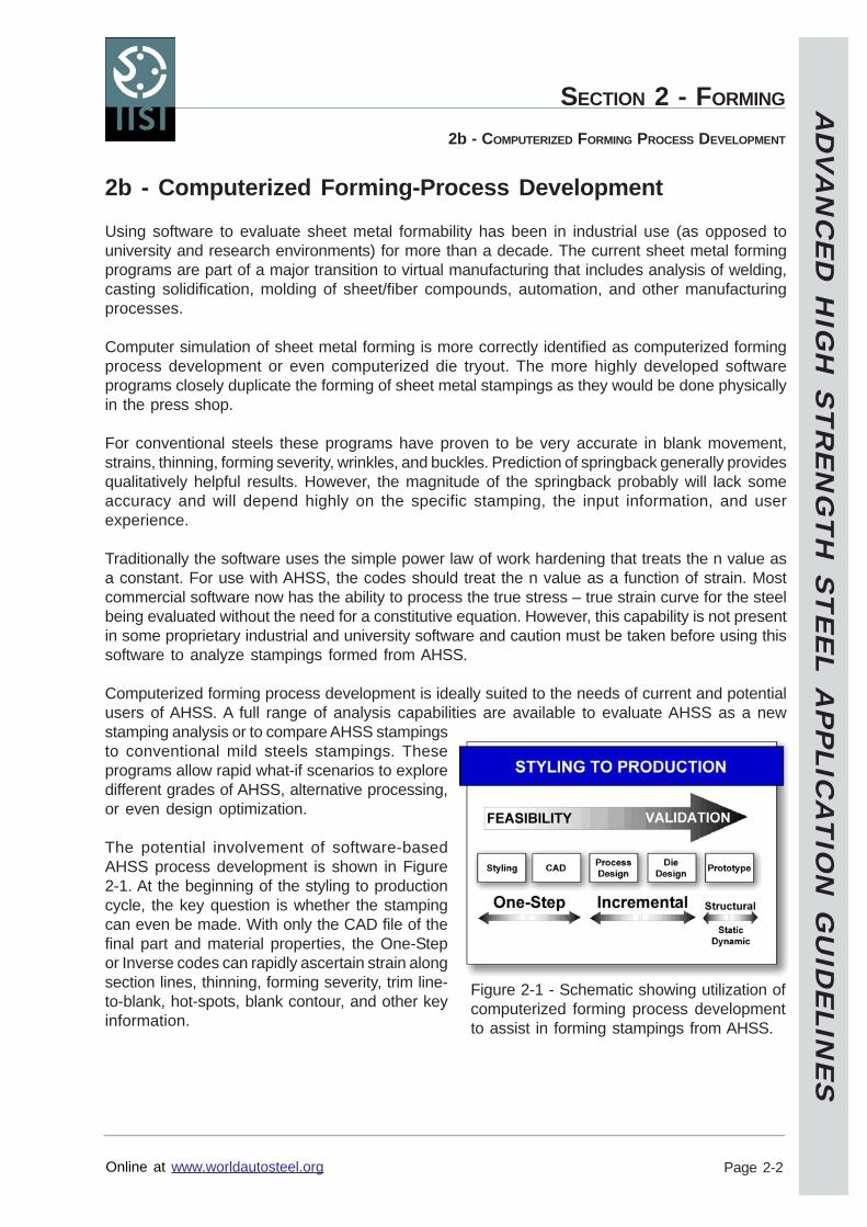
Computerized forming process development is ideally suited to the needs of current and potentialusers of AHSS. A full range of analysis capabilities are available to evaluate AHSS as a newstamping analysis or to compare AHSS stampingsto conventional mild steels stampings. Theseprograms allow rapid what-if scenarios to exploredifferent grades of AHSS, alternative processing,or even design optimization.
The potential involvement of software-basedAHSS process development is shown in Figure2-1. At the beginning of the styling to productioncycle, the key question is whether the stampingcan even be made. With only the CAD file of thefinal part and material properties, the One-Stepor Inverse codes can rapidly ascertain strain alongsection lines, thinning, forming severity, trim line-to-blank, hot-spots, blank contour, and other keyinformation.
Figure 2-1 - Schematic showing utilization ofcomputerized forming process developmentto assist in forming stampings from AHSS.
AD
VA
NC
ED
HIG
H S
TR
EN
GT
H S
TE
EL A
PP
LICA
TIO
N G
UID
ELIN
ES
Online at www.worldautosteel.org
SECTION 2 - FORMING
Page 2-3
2b - COMPUTERIZED FORMING PROCESS DEVELOPMENT
During selection of process and die design parameters, the software will evaluate how each newinput not only affects the outputs listed in the previous paragraph, but also will show wrinkles andgenerate a press-loading curve. The most useful output of the analysis is observing (like a video)the blank being deformed into the final part through a transparent die. Each frame of the video isequivalent to an incremental hit or breakdown stamping. Problem areas or defects in the finalincrement of forming can be traced backwards through the forming stages to the initiation of theproblem. The most comprehensive software allows multi-stage forming, such as progressivedies, transfer presses, or tandem presses. The effects of trimming and other offal removal on thespringback of the part are documented.
Since many applications of AHSS involve load bearing or crash analyses, computerized formingprocess development has special utilization in structural analysis. Previously the part and assemblydesigns were analyzed for static and dynamic capabilities using CAD stampings with initial sheetthickness and as-received yield strength. Often the tests results from real parts did not agree withthe early analyses because real parts were not analyzed. Now virtual parts are generated withpoint to point sheet thickness and strength levels nearly identical to those that will be tested whenthe physical tooling is constructed. Deficiencies of the virtual parts can be identified and correctedby tool, process, or even part-design before tool construction is even begun.
AD
VA
NC
ED
HIG
H S
TR
EN
GT
H S
TE
EL A
PP
LICA
TIO
N G
UID
ELIN
ES
Online at www.worldautosteel.org
SECTION 2 - FORMING
Page 2-4
2c - SHEET FORMINGMECHANICAL PROPERTIES
2c - Sheet Forming
Mechanical Properties
By combining a number of different microstructures not traditionally found in conventional HSS,a wide range of properties are possible with AHSS. This allows steel companies to tailor theprocessing to meet the ever more focused application requirements demanded by the automotiveindustry.
Comparing these AHSS to their conventional HSS counterparts becomes much more difficult.The same minimum tensile strength can be found with a variety of steel types having differentyield strengths. One example is TRIP 450/800, DP 500/800, and CP 700/800 steels with thesame minimum tensile strength with different yield strengths and typical total elongations in therange of 29%, 17%, and 13%, respectively. Some AHSS steels have their properties determinedwhen the steel is produced. However, the properties of TRIP change during deformation as theretained austenite transforms to islands of martensite. The amount and rate of this transformationdepends on the type and amount of deformation, the strain rate, the temperature of the sheetmetal, and other conditions unique to the specific part, tool, and press.
Property data contained in this section cover general trends and reasons why these trends differfrom conventional HSS. Specific data can only be obtained by selecting the exact type, grade,and thickness of AHSS and then contacting the steel supplier for properties expected with theirprocessing of the order.
Yield Strength - Total Elongation Relationships
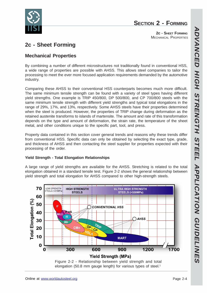
A large range of yield strengths are available for the AHSS. Stretching is related to the totalelongation obtained in a standard tensile test. Figure 2-2 shows the general relationship betweenyield strength and total elongation for AHSS compared to other high-strength steels.
Figure 2-2 - Relationship between yield strength and totalelongation (50.8 mm gauge length) for various types of steel.1
AD
VA
NC
ED
HIG
H S
TR
EN
GT
H S
TE
EL A
PP
LICA
TIO
N G
UID
ELIN
ES
Online at www.worldautosteel.org
SECTION 2 - FORMING
Page 2-5
2c - SHEET FORMINGMECHANICAL PROPERTIES
Note that the families of DP, CP, and TRIP steels generally have higher total elongations thanHSLA steels of equal yield strengths.
Most AHSS steels have no yield point elongation. Some samples of higher strength dual phasegrades and TRIP steels may show YPE but the value typically should be less than 1%. Thesevalues are in contrast with various HSLA grades, which can have YPE values greater than 5%.
Tensile Strength - Total Elongation Relationships
The relationship between ultimate tensile strength and total elongation for the various types ofsteels in Figure 2-3 parallels that observed in Figure 2-2.
When ordering steel based on tensile strength, the DP, CP, and TRIP steels in general still havehigher total elongations than HSLA steels of equal tensile strengths.
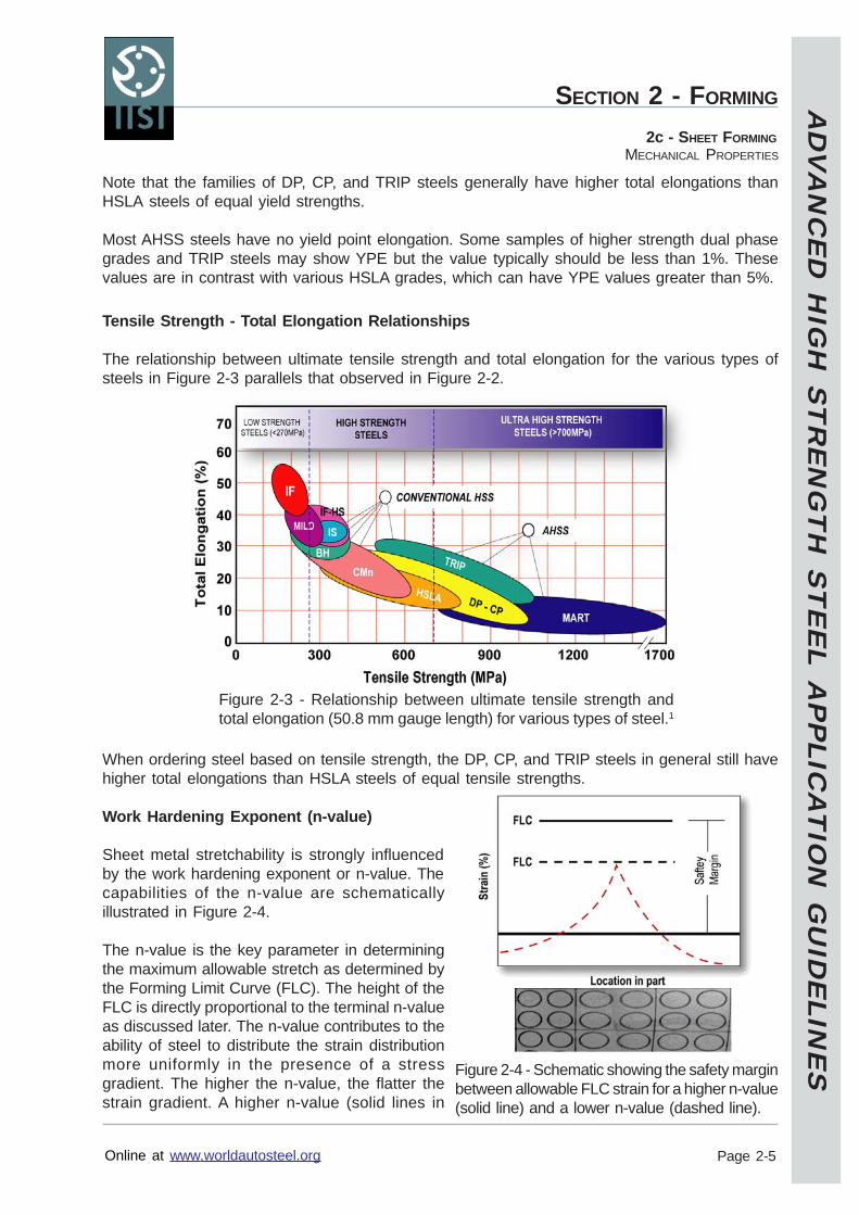
Work Hardening Exponent (n-value)
Sheet metal stretchability is strongly influencedby the work hardening exponent or n-value. Thecapabilities of the n-value are schematicallyillustrated in Figure 2-4.
The n-value is the key parameter in determiningthe maximum allowable stretch as determined bythe Forming Limit Curve (FLC). The height of theFLC is directly proportional to the terminal n-valueas discussed later. The n-value contributes to theability of steel to distribute the strain distributionmore uniformly in the presence of a stressgradient. The higher the n-value, the flatter thestrain gradient. A higher n-value (solid lines in
Figure 2-3 - Relationship between ultimate tensile strength andtotal elongation (50.8 mm gauge length) for various types of steel.1
Figure 2-4 - Schematic showing the safety marginbetween allowable FLC strain for a higher n-value(solid line) and a lower n-value (dashed line).
AD
VA
NC
ED
HIG
H S
TR
EN
GT
H S
TE
EL A
PP
LICA
TIO
N G
UID
ELIN
ES
Online at www.worldautosteel.org
SECTION 2 - FORMING
Page 2-6
2C - SHEET FORMINGMECHANICAL PROPERTIES
Figure 2-4) compared to a lower n-value (dashed lines) means a deeper part can be stretched forequal safety margins or a larger safety margin for equal depth parts.
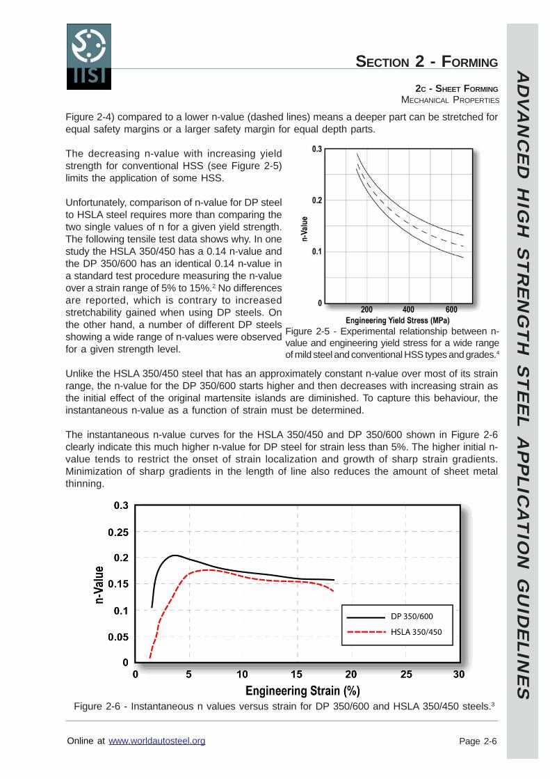
The decreasing n-value with increasing yieldstrength for conventional HSS (see Figure 2-5)limits the application of some HSS.
Unfortunately, comparison of n-value for DP steelto HSLA steel requires more than comparing thetwo single values of n for a given yield strength.The following tensile test data shows why. In onestudy the HSLA 350/450 has a 0.14 n-value andthe DP 350/600 has an identical 0.14 n-value ina standard test procedure measuring the n-valueover a strain range of 5% to 15%.2 No differencesare reported, which is contrary to increasedstretchability gained when using DP steels. Onthe other hand, a number of different DP steelsshowing a wide range of n-values were observedfor a given strength level.
Unlike the HSLA 350/450 steel that has an approximately constant n-value over most of its strainrange, the n-value for the DP 350/600 starts higher and then decreases with increasing strain asthe initial effect of the original martensite islands are diminished. To capture this behaviour, theinstantaneous n-value as a function of strain must be determined.
The instantaneous n-value curves for the HSLA 350/450 and DP 350/600 shown in Figure 2-6clearly indicate this much higher n-value for DP steel for strain less than 5%. The higher initial n-value tends to restrict the onset of strain localization and growth of sharp strain gradients.Minimization of sharp gradients in the length of line also reduces the amount of sheet metalthinning.
Figure 2-5 - Experimental relationship between n-value and engineering yield stress for a wide rangeof mild steel and conventional HSS types and grades.4
Figure 2-6 - Instantaneous n values versus strain for DP 350/600 and HSLA 350/450 steels.3
AD
VA
NC
ED
HIG
H S
TR
EN
GT
H S
TE
EL A
PP
LICA
TIO
N G
UID
ELIN
ES
Online at www.worldautosteel.org
SECTION 2 - FORMING
Page 2-7
2c - SHEET FORMINGMECHANICAL PROPERTIES
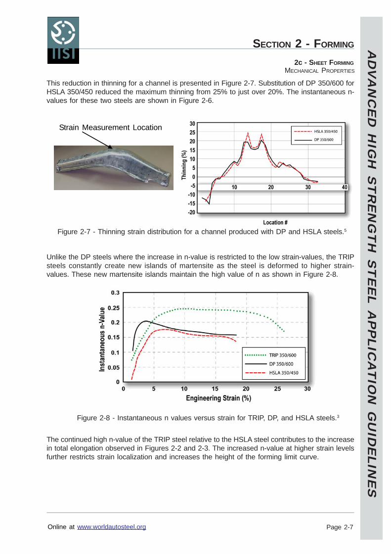
This reduction in thinning for a channel is presented in Figure 2-7. Substitution of DP 350/600 forHSLA 350/450 reduced the maximum thinning from 25% to just over 20%. The instantaneous n-values for these two steels are shown in Figure 2-6.
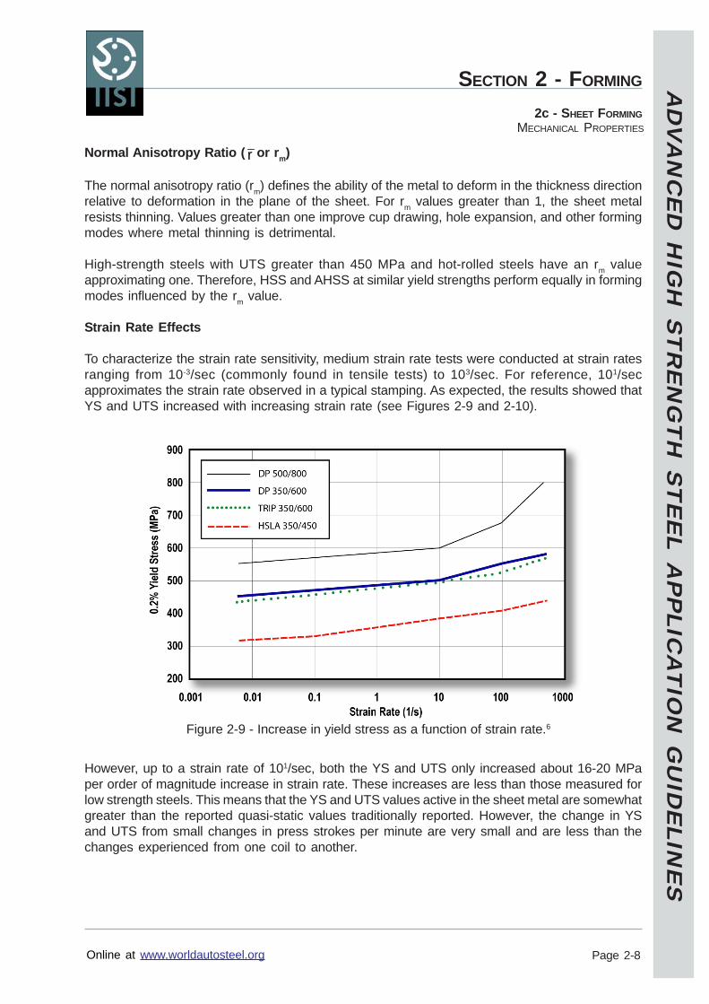
Unlike the DP steels where the increase in n-value is restricted to the low strain-values, the TRIPsteels constantly create new islands of martensite as the steel is deformed to higher strain-values. These new martensite islands maintain the high value of n as shown in Figure 2-8.
The continued high n-value of the TRIP steel relative to the HSLA steel contributes to the increasein total elongation observed in Figures 2-2 and 2-3. The increased n-value at higher strain levelsfurther restricts strain localization and increases the height of the forming limit curve.
Figure 2-7 - Thinning strain distribution for a channel produced with DP and HSLA steels.5
Figure 2-8 - Instantaneous n values versus strain for TRIP, DP, and HSLA steels.3
Strain Measurement Location
AD
VA
NC
ED
HIG
H S
TR
EN
GT
H S
TE
EL A
PP
LICA
TIO
N G
UID
ELIN
ES
Online at www.worldautosteel.org
SECTION 2 - FORMING
Page 2-8
2c - SHEET FORMINGMECHANICAL PROPERTIES
Normal Anisotropy Ratio ( r or rm)
The normal anisotropy ratio (rm) defines the ability of the metal to deform in the thickness directionrelative to deformation in the plane of the sheet. For rm values greater than 1, the sheet metalresists thinning. Values greater than one improve cup drawing, hole expansion, and other formingmodes where metal thinning is detrimental.
High-strength steels with UTS greater than 450 MPa and hot-rolled steels have an rm valueapproximating one. Therefore, HSS and AHSS at similar yield strengths perform equally in formingmodes influenced by the rm value.
Strain Rate Effects
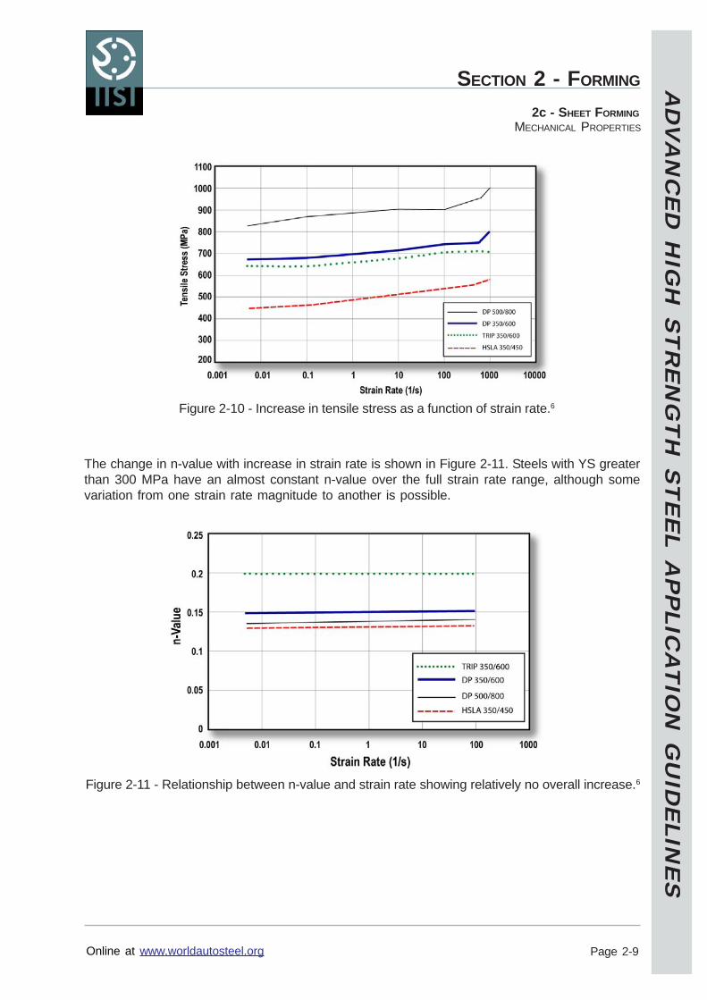
To characterize the strain rate sensitivity, medium strain rate tests were conducted at strain ratesranging from 10-3/sec (commonly found in tensile tests) to 103/sec. For reference, 101/secapproximates the strain rate observed in a typical stamping. As expected, the results showed thatYS and UTS increased with increasing strain rate (see Figures 2-9 and 2-10).
However, up to a strain rate of 101/sec, both the YS and UTS only increased about 16-20 MPaper order of magnitude increase in strain rate. These increases are less than those measured forlow strength steels. This means that the YS and UTS values active in the sheet metal are somewhatgreater than the reported quasi-static values traditionally reported. However, the change in YSand UTS from small changes in press strokes per minute are very small and are less than thechanges experienced from one coil to another.
Figure 2-9 - Increase in yield stress as a function of strain rate.6
AD
VA
NC
ED
HIG
H S
TR
EN
GT
H S
TE
EL A
PP
LICA
TIO
N G
UID
ELIN
ES
Online at www.worldautosteel.org
SECTION 2 - FORMING
Page 2-9
2c - SHEET FORMINGMECHANICAL PROPERTIES
The change in n-value with increase in strain rate is shown in Figure 2-11. Steels with YS greaterthan 300 MPa have an almost constant n-value over the full strain rate range, although somevariation from one strain rate magnitude to another is possible.
Figure 2-10 - Increase in tensile stress as a function of strain rate.6
Figure 2-11 - Relationship between n-value and strain rate showing relatively no overall increase.6
AD
VA
NC
ED
HIG
H S
TR
EN
GT
H S
TE
EL A
PP
LICA
TIO
N G
UID
ELIN
ES
Online at www.worldautosteel.org
SECTION 2 - FORMING
Page 2-10
2c - SHEET FORMINGMECHANICAL PROPERTIES
Bake Hardening and Aging
Strain aging was measured using a typical value for an automotive paint/bake cycle consisting of2% uniaxial pre-strain followed by baking at 170 oC for 30 minutes. Figure 2-12 defines themeasurement for work hardening (B minus A), unloading to C for baking, and reloading to yieldingat D for measurement of bake hardening (D minus B or E minus B). Note that the yield pointelongation phenomenon (shown in Figure 2-12) after prestrain and baking may not occur forAHSS.
Figure 2-13 shows the work hardening and bake hardening increases for the prestrained andbaked tensile specimen. The HSLA shows little or no bake hardening, while AHSS such as DPand TRIP steels shows large positive bake hardening index. The DP steel also has significantlyhigher work hardening than HSLA or TRIP steel because of higher strain hardening at low strains.No aging behaviour of AHSS has been observed due to storage of as-received coils or blanksover a significant length of time at normal room temperatures. Hence, significant mechanicalproperty changes of shipped AHSS products during normal storage conditions are unlikely.
Figure 2-12 - Measurement of work hardening index and bake hardening index.
Figure 2-13 - Comparison of work hardening (WH) andbake hardening (BH) for TRIP, DP, and HSLA steels.7,8

AD
VA
NC
ED
HIG
H S
TR
EN
GT
H S
TE
EL A
PP
LICA
TIO
N G
UID
ELIN
ES
Online at www.worldautosteel.org
SECTION 2 - FORMING
Page 2-11
2c - SHEET FORMINGMECHANICAL PROPERTIES
Key Points
AHSS generally have greater total elongations compared to conventional HSS of equalultimate tensile strengths.DP steels have increased n-values in the initial stages of deformation compared to HSS.These higher n-values help distribute deformation more uniformly in the presence of astress gradient and thereby reduce local thinning.TRIP steels have less initial increase in n-value than DP steels but sustain the increasethroughout the entire deformation process. These higher strength steels can have n-values comparable to mild steels.AHSS and HSS steels with UTS greater than 450 MPa have normal anisotropy values (rm)around one.YS and UTS for AHSS increase only about 16-20 MPa per ten-fold increase in strain rate,which is less than mild steel increases. The n-value changes very little over a 105 increasein strain rate.As-received AHSS does not age-harden in storage.DP and TRIP steels have substantial increase in YS due to a bake hardening effect, whileHSLA steels have almost none.
AD
VA
NC
ED
HIG
H S
TR
EN
GT
H S
TE
EL A
PP
LICA
TIO
N G
UID
ELIN
ES
Online at www.worldautosteel.org
SECTION 2 - FORMING
Page 2-12
2c - SHEET FORMINGFORMING LIMITS
Forming Limits
Knowledge of forming limits is important throughout the entire product design to production cycle.First is the computerized forming process development (virtual die tryout), which requires forminglimits for the selected steel type and grade to assess the forming severity (hot spots) for eachpoint on the stamping. Next is the process and tool design stage where specific features of thetooling are established and again computer-validated against forming limits for the specific steel.Troubleshooting tools for die tryout on the press shop floor utilize forming limits to assess the finalseverity of the part and to track process improvements. Finally, forming limits are used to trackpart severity throughout the production life of the part as the tooling undergoes both intentional(engineering) modifications and unintentional (wear) changes.
Two different types of forming limits are presented in this section. The first is the traditional forminglimit curves that apply to all modes of sheet metal forming. The second is sheared edge stretchinglimits that apply strictly to the problem of stretching the cut edge of sheet metal.
Forming Limit Curves (FLC)
Forming limit curves (FLC) are used routinely in many areas around the world during the design,tryout, and production stages of a stamping. An FLC is a map of strains that indicate the onset ofcritical local necking for different strain paths, represented by major and minor strains. Thesecritical strains not only become the limit of useful deformation but are also the points below whichsafety margins are calculated.
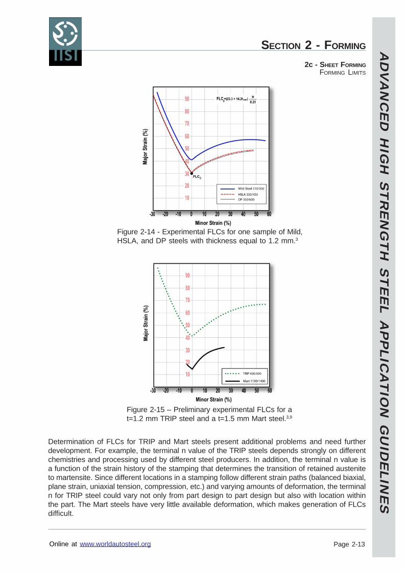
Experimental determination of FLCs involves forming sheet specimens of different widths togenerate different strain paths and measuring the different critical strains. Considerable priorwork has been done with respect to characterizing the minimum value of the FLC as a function onn-value and thickness for different steel types and grades. One equation for FLC0 is given inFigure 2-14.
Examples of experimental FLCs are shown in Figure 2-14 for Mild Steel 170/300, HSLA 350/450,and DP 350/600 with sheet thickness equal to 1.2 mm. All three curves have approximately thesame shape and the minimum value of the major strain generally is predictable from the FLC0equation. Since the HSLA and DP steels have approximately the same terminal (high strain) nvalue (see Figure 2-6), the identical FLCs were expected. The Mild Steel has an elevated FLCbecause of its terminal n value is substantially higher than the HSLA and DP steels tested.
AD
VA
NC
ED
HIG
H S
TR
EN
GT
H S
TE
EL A
PP
LICA
TIO
N G
UID
ELIN
ES
Online at www.worldautosteel.org
SECTION 2 - FORMING
Page 2-13
2c - SHEET FORMINGFORMING LIMITS
Determination of FLCs for TRIP and Mart steels present additional problems and need furtherdevelopment. For example, the terminal n value of the TRIP steels depends strongly on differentchemistries and processing used by different steel producers. In addition, the terminal n value isa function of the strain history of the stamping that determines the transition of retained austeniteto martensite. Since different locations in a stamping follow different strain paths (balanced biaxial,plane strain, uniaxial tension, compression, etc.) and varying amounts of deformation, the terminaln for TRIP steel could vary not only from part design to part design but also with location withinthe part. The Mart steels have very little available deformation, which makes generation of FLCsdifficult.
Figure 2-14 - Experimental FLCs for one sample of Mild,HSLA, and DP steels with thickness equal to 1.2 mm.3
Figure 2-15 – Preliminary experimental FLCs for at=1.2 mm TRIP steel and a t=1.5 mm Mart steel.3,9
AD
VA
NC
ED
HIG
H S
TR
EN
GT
H S
TE
EL A
PP
LICA
TIO
N G
UID
ELIN
ES
Online at www.worldautosteel.org
SECTION 2 - FORMING
Page 2-14
2c - SHEET FORMINGFORMING LIMITS
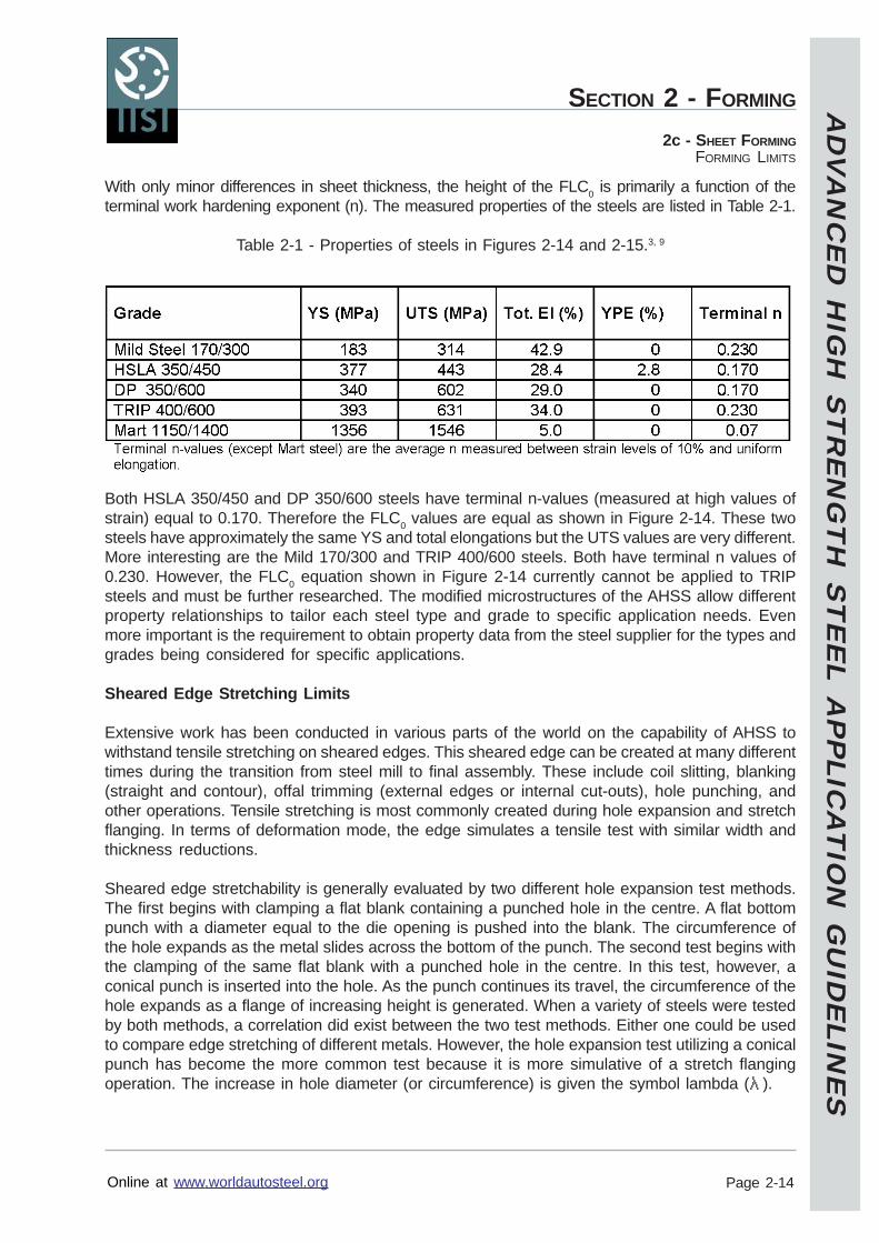
With only minor differences in sheet thickness, the height of the FLC0 is primarily a function of theterminal work hardening exponent (n). The measured properties of the steels are listed in Table 2-1.
Table 2-1 - Properties of steels in Figures 2-14 and 2-15.3, 9
Both HSLA 350/450 and DP 350/600 steels have terminal n-values (measured at high values ofstrain) equal to 0.170. Therefore the FLC0 values are equal as shown in Figure 2-14. These twosteels have approximately the same YS and total elongations but the UTS values are very different.More interesting are the Mild 170/300 and TRIP 400/600 steels. Both have terminal n values of0.230. However, the FLC0 equation shown in Figure 2-14 currently cannot be applied to TRIPsteels and must be further researched. The modified microstructures of the AHSS allow differentproperty relationships to tailor each steel type and grade to specific application needs. Evenmore important is the requirement to obtain property data from the steel supplier for the types andgrades being considered for specific applications.
Sheared Edge Stretching Limits
Extensive work has been conducted in various parts of the world on the capability of AHSS towithstand tensile stretching on sheared edges. This sheared edge can be created at many differenttimes during the transition from steel mill to final assembly. These include coil slitting, blanking(straight and contour), offal trimming (external edges or internal cut-outs), hole punching, andother operations. Tensile stretching is most commonly created during hole expansion and stretchflanging. In terms of deformation mode, the edge simulates a tensile test with similar width andthickness reductions.
Sheared edge stretchability is generally evaluated by two different hole expansion test methods.The first begins with clamping a flat blank containing a punched hole in the centre. A flat bottompunch with a diameter equal to the die opening is pushed into the blank. The circumference ofthe hole expands as the metal slides across the bottom of the punch. The second test begins withthe clamping of the same flat blank with a punched hole in the centre. In this test, however, aconical punch is inserted into the hole. As the punch continues its travel, the circumference of thehole expands as a flange of increasing height is generated. When a variety of steels were testedby both methods, a correlation did exist between the two test methods. Either one could be usedto compare edge stretching of different metals. However, the hole expansion test utilizing a conicalpunch has become the more common test because it is more simulative of a stretch flangingoperation. The increase in hole diameter (or circumference) is given the symbol lambda ( ).
AD
VA
NC
ED
HIG
H S
TR
EN
GT
H S
TE
EL A
PP
LICA
TIO
N G
UID
ELIN
ES
Online at www.worldautosteel.org
SECTION 2 - FORMING
Page 2-15
2c - SHEET FORMINGFORMING LIMITS
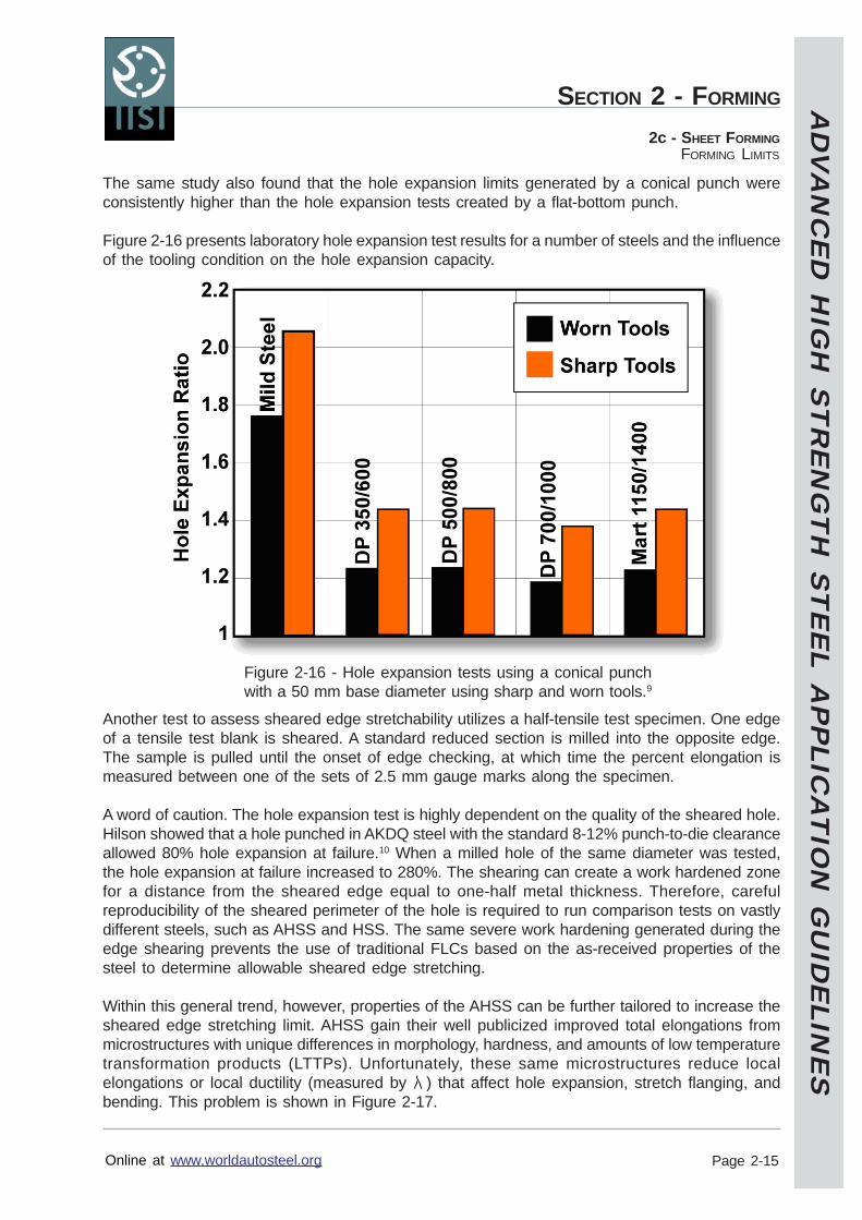
The same study also found that the hole expansion limits generated by a conical punch wereconsistently higher than the hole expansion tests created by a flat-bottom punch.
Figure 2-16 presents laboratory hole expansion test results for a number of steels and the influenceof the tooling condition on the hole expansion capacity.
Another test to assess sheared edge stretchability utilizes a half-tensile test specimen. One edgeof a tensile test blank is sheared. A standard reduced section is milled into the opposite edge.The sample is pulled until the onset of edge checking, at which time the percent elongation ismeasured between one of the sets of 2.5 mm gauge marks along the specimen.
A word of caution. The hole expansion test is highly dependent on the quality of the sheared hole.Hilson showed that a hole punched in AKDQ steel with the standard 8-12% punch-to-die clearanceallowed 80% hole expansion at failure.10 When a milled hole of the same diameter was tested,the hole expansion at failure increased to 280%. The shearing can create a work hardened zonefor a distance from the sheared edge equal to one-half metal thickness. Therefore, carefulreproducibility of the sheared perimeter of the hole is required to run comparison tests on vastlydifferent steels, such as AHSS and HSS. The same severe work hardening generated during theedge shearing prevents the use of traditional FLCs based on the as-received properties of thesteel to determine allowable sheared edge stretching.
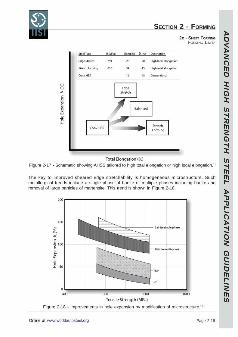
Within this general trend, however, properties of the AHSS can be further tailored to increase thesheared edge stretching limit. AHSS gain their well publicized improved total elongations frommicrostructures with unique differences in morphology, hardness, and amounts of low temperaturetransformation products (LTTPs). Unfortunately, these same microstructures reduce localelongations or local ductility (measured by ) that affect hole expansion, stretch flanging, andbending. This problem is shown in Figure 2-17.
Figure 2-16 - Hole expansion tests using a conical punchwith a 50 mm base diameter using sharp and worn tools.9
AD
VA
NC
ED
HIG
H S
TR
EN
GT
H S
TE
EL A
PP
LICA
TIO
N G
UID
ELIN
ES
Online at www.worldautosteel.org
SECTION 2 - FORMING
Page 2-16
2c - SHEET FORMINGFORMING LIMITS
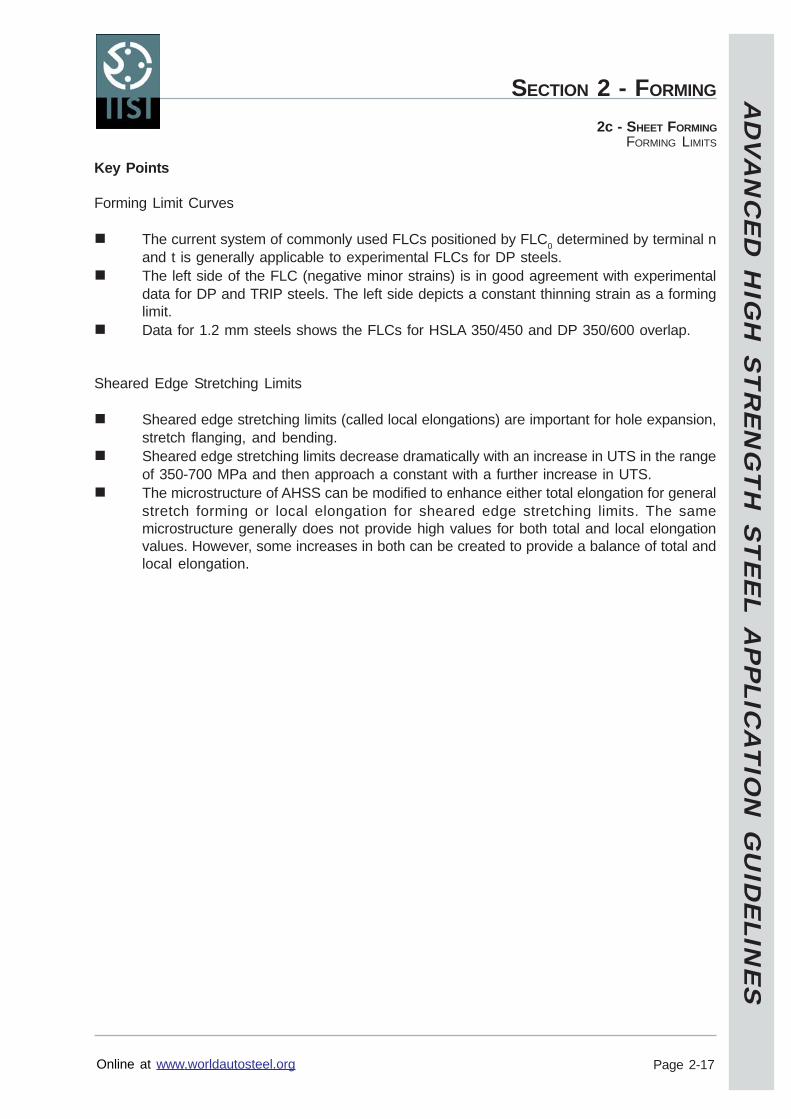
The key to improved sheared edge stretchability is homogeneous microstructure. Suchmetallurgical trends include a single phase of banite or multiple phases including banite andremoval of large particles of martensite. This trend is shown in Figure 2-18.
Figure 2-17 - Schematic showing AHSS tailored to high total elongation or high local elongation.11
Figure 2-18 - Improvements in hole expansion by modification of microstructure.12
AD
VA
NC
ED
HIG
H S
TR
EN
GT
H S
TE
EL A
PP
LICA
TIO
N G
UID
ELIN
ES
Online at www.worldautosteel.org
SECTION 2 - FORMING
Page 2-17
2c - SHEET FORMINGFORMING LIMITS
Key Points
Forming Limit Curves
The current system of commonly used FLCs positioned by FLC0 determined by terminal nand t is generally applicable to experimental FLCs for DP steels.The left side of the FLC (negative minor strains) is in good agreement with experimentaldata for DP and TRIP steels. The left side depicts a constant thinning strain as a forminglimit.Data for 1.2 mm steels shows the FLCs for HSLA 350/450 and DP 350/600 overlap.
Sheared Edge Stretching Limits
Sheared edge stretching limits (called local elongations) are important for hole expansion,stretch flanging, and bending.Sheared edge stretching limits decrease dramatically with an increase in UTS in the rangeof 350-700 MPa and then approach a constant with a further increase in UTS.The microstructure of AHSS can be modified to enhance either total elongation for generalstretch forming or local elongation for sheared edge stretching limits. The samemicrostructure generally does not provide high values for both total and local elongationvalues. However, some increases in both can be created to provide a balance of total andlocal elongation.
AD
VA
NC
ED
HIG
H S
TR
EN
GT
H S
TE
EL A
PP
LICA
TIO
N G
UID
ELIN
ES
Online at www.worldautosteel.org
SECTION 2 - FORMING
Page 2-18
2c - SHEET FORMINGFORMING MODES
Forming Modes
Part designers are interested in the forming capabilities of the steels they specify. This is true ofHSS and even more so for AHSS. Unfortunately complex stampings are composed of severaldifferent basic forming modes, which react to a different set of mechanical properties. Likewise,formability of steel, and especially AHSS, cannot be characterized by a single number. Therefore,formability comparisons of AHSS to conventional HSS must be done for each basic formingmode. In this section, three general groups (stretching, cup drawing, and bending) are reviewed.
Stretching
As a general rule the depth of a part by stretching increases as the work hardening exponent (n)increases. As discussed in the Mechanical Property unit, an increase in n value can increase:
1) The allowable stretch as determined by the forming limit curve (FLC).2) Increase the ability of steel to distribute the strain distribution more uniformly in the
presence of a stress gradient.
DP steels have an increased n value at low valuesof strain compared to HSS (see Figure 2-6).Therefore, DP steels have increased tendencyto flatten strain gradients. Part designers canbenefit from AHSS for all stamping areas that areformed in pure stretch, such as embossments,character lines, and other design features withlocalized strain gradients (see Figure 2-19). Peakstrain reduction in these gradients also means lesslocalized thinning for in-service requirements.
At higher strains, DP steels have n values similarto conventional HSS. Therefore, traditionalformulas used to set the height of the FLC usedfor HSLA can be used for DP steels whencompared at equal yield strengths (see Figure 2-14). However, when comparisons are made between DP and HSLA steels with equal tensilestrengths, the DP steels do have higher FLCs. Caution must be taken when those stretch operations(embossments and other design features) are performed on prior-deformed areas. Due to therapid work hardening rate for AHSS, the residual formability from the prior operation may be quitedifferent from that for conventional HSS.
TRIP steels have high values of n compared to HSS throughout their entire strain range (seeFigure 2-8). The continual high n means a much more powerful reaction to suppress localizationof strain generated by design features in the stamping. The higher terminal (high strain) n valuealso means a higher FLC (see Figure 2-15), where, for example, the FLC for the TRIP 350/600steel approximates that of a Mild steel.
In stretch forming, the TRIP steel has an additional advantage compared to DP and conventionalHSS. As the strain begins to localize at the high stress locations in the stamping, the deformationcauses additional transformation from retained austenite to martensite. This further strengthensthe deformation zone and forces redistribution of deformation to areas of less strain.
Figure 2-19 Stretch forming generatedby a rounded or flat bottom punch.
AD
VA
NC
ED
HIG
H S
TR
EN
GT
H S
TE
EL A
PP
LICA
TIO
N G
UID
ELIN
ES
Online at www.worldautosteel.org
SECTION 2 - FORMING
Page 2-19
2c - SHEET FORMINGFORMING MODES
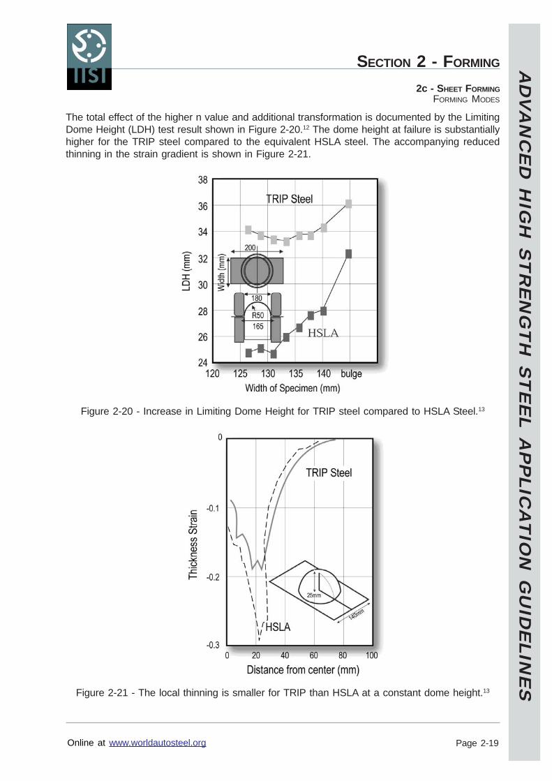
The total effect of the higher n value and additional transformation is documented by the LimitingDome Height (LDH) test result shown in Figure 2-20.12 The dome height at failure is substantiallyhigher for the TRIP steel compared to the equivalent HSLA steel. The accompanying reducedthinning in the strain gradient is shown in Figure 2-21.
Figure 2-20 - Increase in Limiting Dome Height for TRIP steel compared to HSLA Steel.13
Figure 2-21 - The local thinning is smaller for TRIP than HSLA at a constant dome height.13
AD
VA
NC
ED
HIG
H S
TR
EN
GT
H S
TE
EL A
PP
LICA
TIO
N G
UID
ELIN
ES
Online at www.worldautosteel.org
SECTION 2 - FORMING
Page 2-20
2c - SHEET FORMINGFORMING MODES
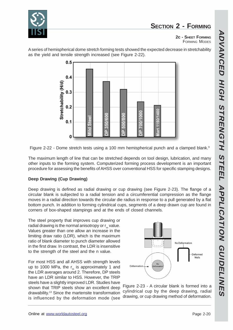
A series of hemispherical dome stretch forming tests showed the expected decrease in stretchabilityas the yield and tensile strength increased (see Figure 2-22).
Figure 2-22 - Dome stretch tests using a 100 mm hemispherical punch and a clamped blank.9
The maximum length of line that can be stretched depends on tool design, lubrication, and manyother inputs to the forming system. Computerized forming process development is an importantprocedure for assessing the benefits of AHSS over conventional HSS for specific stamping designs.
Deep Drawing (Cup Drawing)
Deep drawing is defined as radial drawing or cup drawing (see Figure 2-23). The flange of acircular blank is subjected to a radial tension and a circumferential compression as the flangemoves in a radial direction towards the circular die radius in response to a pull generated by a flatbottom punch. In addition to forming cylindrical cups, segments of a deep drawn cup are found incorners of box-shaped stampings and at the ends of closed channels.
The steel property that improves cup drawing orradial drawing is the normal anisotropy or rm value.Values greater than one allow an increase in thelimiting draw ratio (LDR), which is the maximumratio of blank diameter to punch diameter allowedin the first draw. In contrast, the LDR is insensitiveto the strength of the steel and the n value.
For most HSS and all AHSS with strength levelsup to 1000 MPa, the rm is approximately 1 andthe LDR averages around 2. Therefore, DP steelshave an LDR similar to HSS. However, the TRIPsteels have a slightly improved LDR. Studies haveshown that TRIP steels show an excellent deepdrawability.13 Since the martensite transformationis influenced by the deformation mode (see
Figure 2-23 - A circular blank is formed into acylindrical cup by the deep drawing, radialdrawing, or cup drawing method of deformation.
AD
VA
NC
ED
HIG
H S
TR
EN
GT
H S
TE
EL A
PP
LICA
TIO
N G
UID
ELIN
ES
Online at www.worldautosteel.org
SECTION 2 - FORMING
Page 2-21
2c - SHEET FORMINGFORMING MODES
Figure 2-24), the amount of transformed martensite generated by shrink flanging in the flangearea is less than the plane strain deformation in the cup wall. This difference in transformationfrom retained austenite to martensite makes the wall area stronger than the flange area, therebyincreasing the LDR.
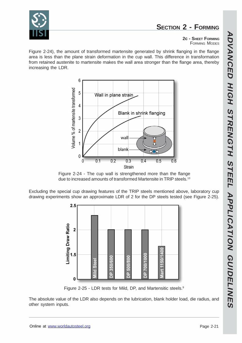
Excluding the special cup drawing features of the TRIP steels mentioned above, laboratory cupdrawing experiments show an approximate LDR of 2 for the DP steels tested (see Figure 2-25).
Figure 2-25 - LDR tests for Mild, DP, and Martensitic steels.9
The absolute value of the LDR also depends on the lubrication, blank holder load, die radius, andother system inputs.
Figure 2-24 - The cup wall is strengthened more than the flangedue to increased amounts of transformed Martensite in TRIP steels.13
AD
VA
NC
ED
HIG
H S
TR
EN
GT
H S
TE
EL A
PP
LICA
TIO
N G
UID
ELIN
ES
Online at www.worldautosteel.org
SECTION 2 - FORMING
Page 2-22
2c - SHEET FORMINGFORMING MODES
Bending
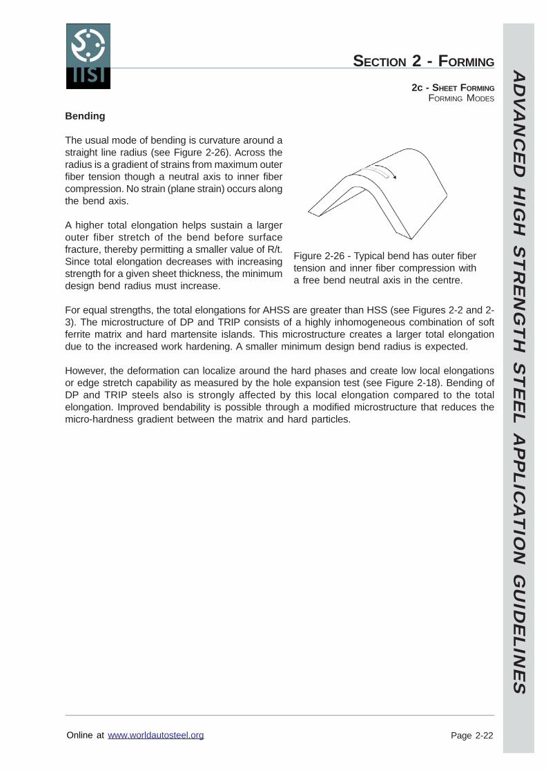
The usual mode of bending is curvature around astraight line radius (see Figure 2-26). Across theradius is a gradient of strains from maximum outerfiber tension though a neutral axis to inner fibercompression. No strain (plane strain) occurs alongthe bend axis.
A higher total elongation helps sustain a largerouter fiber stretch of the bend before surfacefracture, thereby permitting a smaller value of R/t.Since total elongation decreases with increasingstrength for a given sheet thickness, the minimumdesign bend radius must increase.
For equal strengths, the total elongations for AHSS are greater than HSS (see Figures 2-2 and 2-3). The microstructure of DP and TRIP consists of a highly inhomogeneous combination of softferrite matrix and hard martensite islands. This microstructure creates a larger total elongationdue to the increased work hardening. A smaller minimum design bend radius is expected.
However, the deformation can localize around the hard phases and create low local elongationsor edge stretch capability as measured by the hole expansion test (see Figure 2-18). Bending ofDP and TRIP steels also is strongly affected by this local elongation compared to the totalelongation. Improved bendability is possible through a modified microstructure that reduces themicro-hardness gradient between the matrix and hard particles.
Figure 2-26 - Typical bend has outer fibertension and inner fiber compression witha free bend neutral axis in the centre.
AD
VA
NC
ED
HIG
H S
TR
EN
GT
H S
TE
EL A
PP
LICA
TIO
N G
UID
ELIN
ES
Online at www.worldautosteel.org
SECTION 2 - FORMING
Page 2-23
2c - SHEET FORMINGFORMING MODES
Key Points
Stretching
DP steel has a higher initial n value than TRIP steel, which helps to flatten emerging straingradients and localized thinning. Stretch form features such as embossments can beslightly sharper or deeper. DP steel does not have a higher FLC compared to HSS withcomparable YS.TRIP steels benefit from a higher n throughout the deformation process, which helps toflatten emerging strain gradients and localized thinning. In addition, the height of the FLCis increased and higher values of strain are allowed before failure.The limited stretchability of both HSS and AHSS (compared to mild steels) increases theimportance of product design, change of forming mode, utilization of a preform stage,lubricant selection, and other process design options.
Deep Drawing (Cup Drawing)
The LDR for both HSS and DP steels is approximately 2 because the rm value for mosthigher strength steels is approximately 1.The LDR for TRIP steel is slightly greater than two because transformation strengtheningin the cup wall is greater than equivalent strengthening in the deforming flange.
Bending
For DP and TRIP steels, the local elongation influences the minimum R/t ratio more thanthe total elongation. The microstructure of the DP and TRIP steels can be modified toincrease the local elongation and improve bendability.
AD
VA
NC
ED
HIG
H S
TR
EN
GT
H S
TE
EL A
PP
LICA
TIO
N G
UID
ELIN
ES
Online at www.worldautosteel.org
SECTION 2 - FORMING
Page 2-24
2c - SHEET FORMINGTOOL DESIGN
Tool Design
The primary concerns for tool design for forming AHSS are:1) Increased forces required to form the sheet metal.2) Need for additional tool features for increased springback compensation.
Tool Materials
In general, the existing tool and die shop procedures to select the appropriate die material can beused to select dies made to stamp AHSS grades. However, the considerably higher strength levelof these grades exerts proportionally increased load on the die material. AHSS might reachhardness values 4-5 times higher than mild steel grades. This is partially due to the microstructureof the sheet metal itself since some grades include martensitic phases for the required strength.For the martensitic grades (Mart) the basic structure is martensite with tensile strengths approaching1700 MPa.
The higher forces required to form AHSS require increased attention to tool specifications. Thethree primary areas are:
Stiffness and toughness of the tool substrate for failure protection.Harder tool surface finishes for wear protection.Surface roughness of the tool.
Lifetime and performance of a particular drawing die is primarily determined by the acceptedamount of wear/galling between maintenance periods. When selecting die material, some of thekey elements that affect the specification of the die material are:
Sheet metal: strength, thickness, surface coating.Die: construction, machineability, radii sharpness, surface finish.Lubrication.Cost per part.
AHSS characteristics must be determined when designing tools. First is the initial, as-receivedyield strength, which is the minimum yield strength throughout the entire sheet. Second is theincrease in strength level, which can be substantial for stampings that undergo high strain levels.These two factors acting in tandem can greatly increase the local load. This local load increasemostly accelerates the wear of draw radii with a less pronounced effect on other surfaces.
Counteracting this load increase can involve a reduction in sheet thickness. Thickness reductionfor weight saving is one primary reason for applications of AHSS. Unfortunately, the combinationof reduced thickness and higher strength in the steel increases the tendency to wrinkle. Higherblankholder loads are required to suppress these wrinkles. Any formation of wrinkles will increasethe local load and accelerate the wear effects.
Tool steel inserts for forming dies must be selected according to the work material and the severityof the forming. Surface coatings are recommended for DP 350/600 and higher grades. Whencoatings are used, it is important that the substrate has sufficient hardness/strength to avoidplastic deformation of the tool surface - even locally. Therefore a separate surface hardening,such as nitriding, can be used before the coating is applied. Before coating, it is important to usethe tool as a pre-production tool to allow the tool to set, and to provide time for tool to adjust.
AD
VA
NC
ED
HIG
H S
TR
EN
GT
H S
TE
EL A
PP
LICA
TIO
N G
UID
ELIN
ES
Online at www.worldautosteel.org
SECTION 2 - FORMING
Page 2-25
2c - SHEET FORMINGTOOL DESIGN
Surface roughness must be as low as possible before coating. Ra values below 0.2 µm arerecommended. Steel inserts of 1.2379 or 1.2382 with a TiC/TiN coating are recommended forlocal high pressure die areas wearing the zinc of galvanized blanks.
Tool steels for cutting, trimming, and punching tools must be selected in a similar way. A toolhardness between 58 and 62 HRC is recommended. Coatings may be used to reduce tool wear,but for the highest strength steels (above 1000 MPa tensile strength) use of coatings only generateslimited further improvements. At this level of steel strength, coating failures occur due to localdeformation of the die material substrate. Heat treated (hardened) cutter knives of 1.2379 or1.2383 show minor wear of the cutter edge. The radial shear gap should be around 10% of theblank thickness.
High performance tool steels, such as powder metallurgy (PM) grades, are almost alwayseconomical, despite their higher price, because of their low wear rate. Figure 2-27 shows therelative tool wear when punching mild steel with conventional tool steel (A) and punching of DP350/600 with an uncoated (B) and coated (C) PM tool steel.
Figure 2-27 - Tool wear results for different surface treatments using mild steel (A) for a reference of 1.14
A = Mild steel formed with 1.2363 tool steel dies (X100CrMoV5/1; US A2; Japan SKD 12)B = DP 350/600 steel formed with 1.3344 tool steel dies (carbon 1.20%, vanadium 3%)C = DP 350/600 steel formed with 1.3344 tool steel dies + hard surface CVD
AD
VA
NC
ED
HIG
H S
TR
EN
GT
H S
TE
EL A
PP
LICA
TIO
N G
UID
ELIN
ES
Online at www.worldautosteel.org
SECTION 2 - FORMING
Page 2-26
2c - SHEET FORMINGTOOL DESIGN
Research on different surface treatments for a hat-profile drawing with draw beads showed asimilar effect of coated surfaces on a cast iron die and a tool steel die (see Figure 2-28).
GGG70L = Spheroid graphite bearing cast iron, flame hardened 1.2379 = Tool steel (X155CrMo12/1; US D2; Japan SKD 11)
Figure 2-28 - Surface treatment effects on tool wear, DP steel EG, 1mm.15
Ceramic tool inserts have extreme hardness for wear resistance, high heat resistance, and optimumtribological behaviour, but have poor machineability and severe brittleness. High costs are offsetby reduced maintenance and increased productivity. While not commonly used, the ceramic toolinserts offer a possible solution to high interface loading and wear.
Tool Design Issues
Goals for springback compensation:Design out springback in the first draw stage to eliminate additional costly correctiveoperations.Consider strain path and reduce the number of bend/unbend scenarios.Adequate strain levels in the panel must be achieved to avoid greaterspringback and sidewall curl.Higher press forces are experienced on the structure of the tool.
Concerns for trim and pierce tool design:Engineer trim tools to withstand higher loads since AHSS have higher tensile strengththan conventional high-strength steels.Proper support for the trim stock during trim operation is very important to minimize edgecracking.Modify trim schedule to minimize elastic recovery.Shedding of scrap can be a problem because springback of DP steel can cause scrap tostick very firmly in the tool.
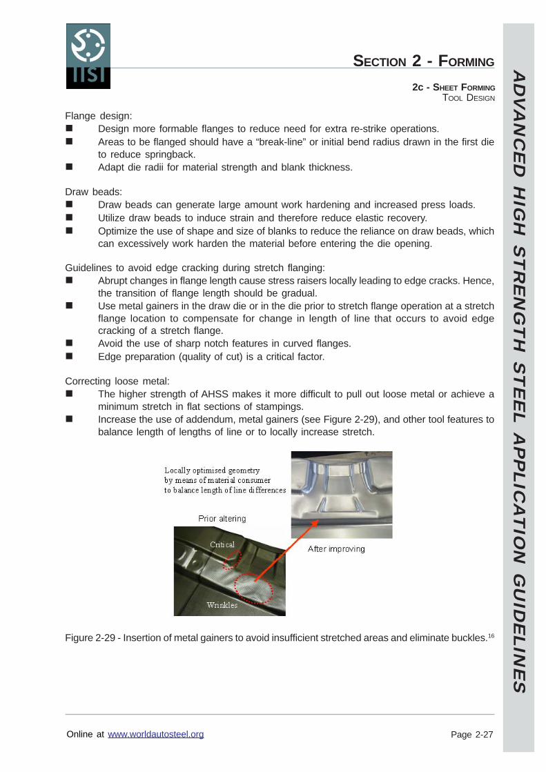
AD
VA
NC
ED
HIG
H S
TR
EN
GT
H S
TE
EL A
PP
LICA
TIO
N G
UID
ELIN
ES
Online at www.worldautosteel.org
SECTION 2 - FORMING
Page 2-27
2c - SHEET FORMINGTOOL DESIGN
Flange design:Design more formable flanges to reduce need for extra re-strike operations.Areas to be flanged should have a “break-line” or initial bend radius drawn in the first dieto reduce springback.Adapt die radii for material strength and blank thickness.
Draw beads:Draw beads can generate large amount work hardening and increased press loads.Utilize draw beads to induce strain and therefore reduce elastic recovery.Optimize the use of shape and size of blanks to reduce the reliance on draw beads, whichcan excessively work harden the material before entering the die opening.
Guidelines to avoid edge cracking during stretch flanging:Abrupt changes in flange length cause stress raisers locally leading to edge cracks. Hence,the transition of flange length should be gradual.Use metal gainers in the draw die or in the die prior to stretch flange operation at a stretchflange location to compensate for change in length of line that occurs to avoid edgecracking of a stretch flange.Avoid the use of sharp notch features in curved flanges.Edge preparation (quality of cut) is a critical factor.
Correcting loose metal:The higher strength of AHSS makes it more difficult to pull out loose metal or achieve aminimum stretch in flat sections of stampings.Increase the use of addendum, metal gainers (see Figure 2-29), and other tool features tobalance length of lengths of line or to locally increase stretch.
Figure 2-29 - Insertion of metal gainers to avoid insufficient stretched areas and eliminate buckles.16
AD
VA
NC
ED
HIG
H S
TR
EN
GT
H S
TE
EL A
PP
LICA
TIO
N G
UID
ELIN
ES
Online at www.worldautosteel.org
SECTION 2 - FORMING
Page 2-28
2c - SHEET FORMINGTOOL DESIGN
Prototype Tools
For prototyping tools, normally soft tool materials are used and tool surfaces are not protected bywear resistant coatings during tool try out. When laser cut blanks of AHSS are used during tryout, the blank holder surface may be damaged due to the high hardness in the cut edges.
Measures to be taken:Close control of laser cutting parameters in order to reduce burr and hardness.Deburr of laser cut blanks.
Soft tools may be used for manufacturing prototype parts and the inserts may also be used toeliminate local wrinkles or buckles. However, soft tools should not be used to assessmanufacturability and springback of AHSS parts.
Key Points
Areas of concern are the higher working loads that require better tool materials and coatingsfor both failure protection and wear protection.The higher initial yield strengths of AHSS, plus the increased work hardening of DP andTRIP steels can increase the working loads of these steels by a factor 3 or 4 compared tomild steels.AHSS hardness values might increase by a factor 4 or 5 over those of mild steel.Powder metallurgy (PM) tools maybe recommended for some AHSS applications.Normal tool design parameters will have to be modified to incorporate more aggressivespringback compensation techniques.Design process to minimize wrinkling. This leads to higher loads and more tool wear.
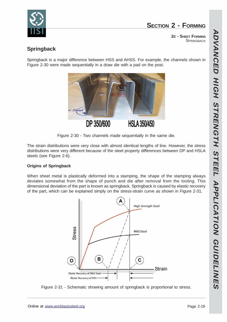
AD
VA
NC
ED
HIG
H S
TR
EN
GT
H S
TE
EL A
PP
LICA
TIO
N G
UID
ELIN
ES
Online at www.worldautosteel.org
SECTION 2 - FORMING
Page 2-29
2c - SHEET FORMINGSPRINGBACK
Springback
Springback is a major difference between HSS and AHSS. For example, the channels shown inFigure 2-30 were made sequentially in a draw die with a pad on the post.
Figure 2-30 - Two channels made sequentially in the same die.
The strain distributions were very close with almost identical lengths of line. However, the stressdistributions were very different because of the steel property differences between DP and HSLAsteels (see Figure 2-6).
Origins of Springback
When sheet metal is plastically deformed into a stamping, the shape of the stamping alwaysdeviates somewhat from the shape of punch and die after removal from the tooling. Thisdimensional deviation of the part is known as springback. Springback is caused by elastic recoveryof the part, which can be explained simply on the stress-strain curve as shown in Figure 2-31.
Figure 2-31 - Schematic showing amount of springback is proportional to stress.
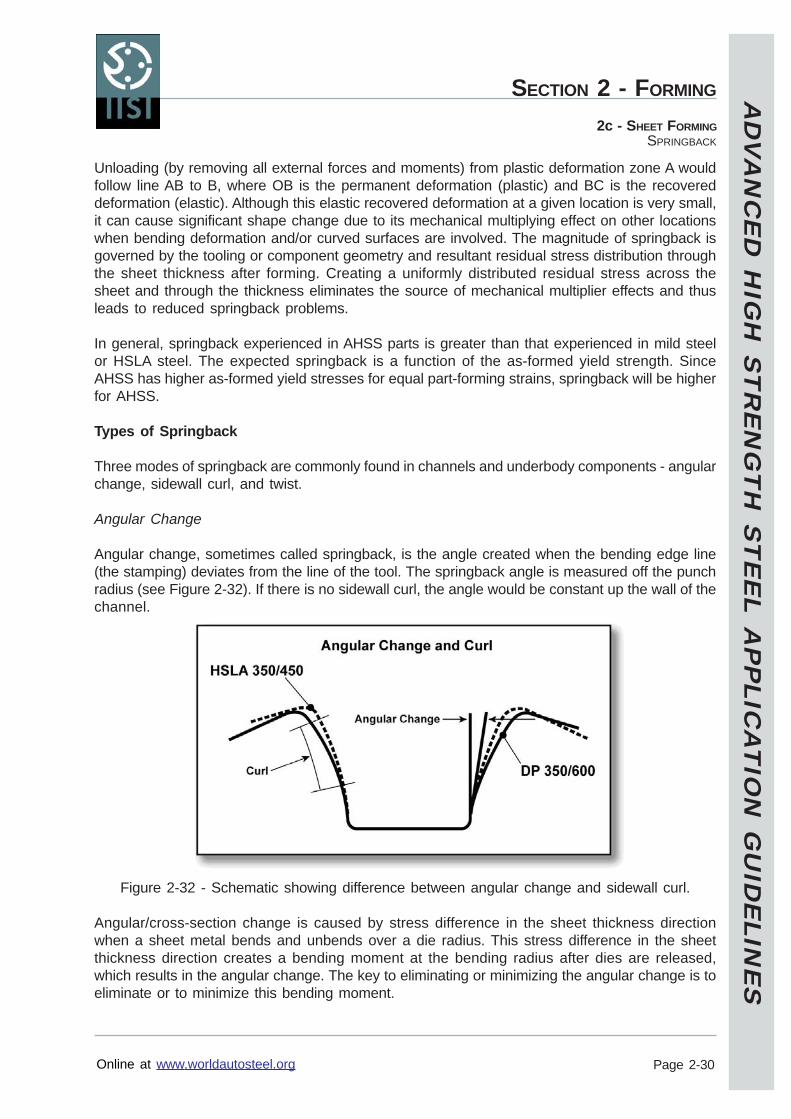
AD
VA
NC
ED
HIG
H S
TR
EN
GT
H S
TE
EL A
PP
LICA
TIO
N G
UID
ELIN
ES
Online at www.worldautosteel.org
SECTION 2 - FORMING
Page 2-30
2c - SHEET FORMINGSPRINGBACK
Unloading (by removing all external forces and moments) from plastic deformation zone A wouldfollow line AB to B, where OB is the permanent deformation (plastic) and BC is the recovereddeformation (elastic). Although this elastic recovered deformation at a given location is very small,it can cause significant shape change due to its mechanical multiplying effect on other locationswhen bending deformation and/or curved surfaces are involved. The magnitude of springback isgoverned by the tooling or component geometry and resultant residual stress distribution throughthe sheet thickness after forming. Creating a uniformly distributed residual stress across thesheet and through the thickness eliminates the source of mechanical multiplier effects and thusleads to reduced springback problems.
In general, springback experienced in AHSS parts is greater than that experienced in mild steelor HSLA steel. The expected springback is a function of the as-formed yield strength. SinceAHSS has higher as-formed yield stresses for equal part-forming strains, springback will be higherfor AHSS.
Types of Springback
Three modes of springback are commonly found in channels and underbody components - angularchange, sidewall curl, and twist.
Angular Change
Angular change, sometimes called springback, is the angle created when the bending edge line(the stamping) deviates from the line of the tool. The springback angle is measured off the punchradius (see Figure 2-32). If there is no sidewall curl, the angle would be constant up the wall of thechannel.
Figure 2-32 - Schematic showing difference between angular change and sidewall curl.
Angular/cross-section change is caused by stress difference in the sheet thickness directionwhen a sheet metal bends and unbends over a die radius. This stress difference in the sheetthickness direction creates a bending moment at the bending radius after dies are released,which results in the angular change. The key to eliminating or minimizing the angular change is toeliminate or to minimize this bending moment.
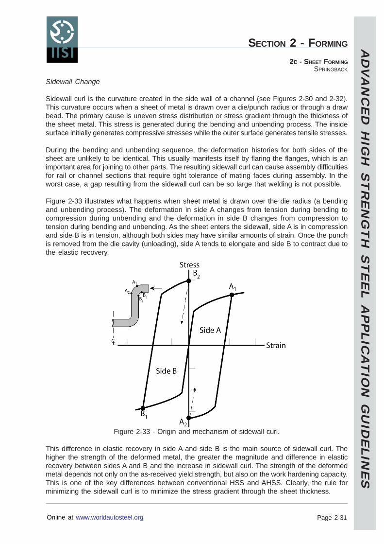
AD
VA
NC
ED
HIG
H S
TR
EN
GT
H S
TE
EL A
PP
LICA
TIO
N G
UID
ELIN
ES
Online at www.worldautosteel.org
SECTION 2 - FORMING
Page 2-31
2c - SHEET FORMINGSPRINGBACK
Sidewall Change
Sidewall curl is the curvature created in the side wall of a channel (see Figures 2-30 and 2-32).This curvature occurs when a sheet of metal is drawn over a die/punch radius or through a drawbead. The primary cause is uneven stress distribution or stress gradient through the thickness ofthe sheet metal. This stress is generated during the bending and unbending process. The insidesurface initially generates compressive stresses while the outer surface generates tensile stresses.
During the bending and unbending sequence, the deformation histories for both sides of thesheet are unlikely to be identical. This usually manifests itself by flaring the flanges, which is animportant area for joining to other parts. The resulting sidewall curl can cause assembly difficultiesfor rail or channel sections that require tight tolerance of mating faces during assembly. In theworst case, a gap resulting from the sidewall curl can be so large that welding is not possible.
Figure 2-33 illustrates what happens when sheet metal is drawn over the die radius (a bendingand unbending process). The deformation in side A changes from tension during bending tocompression during unbending and the deformation in side B changes from compression totension during bending and unbending. As the sheet enters the sidewall, side A is in compressionand side B is in tension, although both sides may have similar amounts of strain. Once the punchis removed from the die cavity (unloading), side A tends to elongate and side B to contract due tothe elastic recovery.
Figure 2-33 - Origin and mechanism of sidewall curl.
This difference in elastic recovery in side A and side B is the main source of sidewall curl. Thehigher the strength of the deformed metal, the greater the magnitude and difference in elasticrecovery between sides A and B and the increase in sidewall curl. The strength of the deformedmetal depends not only on the as-received yield strength, but also on the work hardening capacity.This is one of the key differences between conventional HSS and AHSS. Clearly, the rule forminimizing the sidewall curl is to minimize the stress gradient through the sheet thickness.
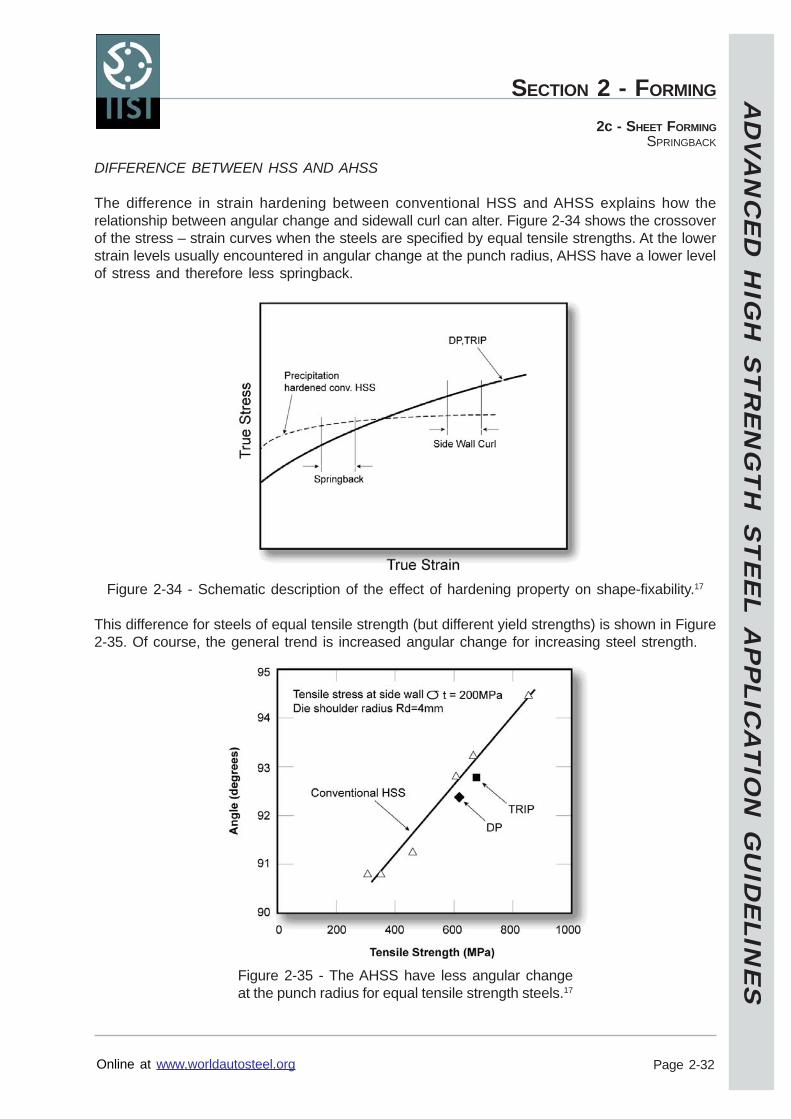
AD
VA
NC
ED
HIG
H S
TR
EN
GT
H S
TE
EL A
PP
LICA
TIO
N G
UID
ELIN
ES
Online at www.worldautosteel.org
SECTION 2 - FORMING
Page 2-32
2c - SHEET FORMINGSPRINGBACK
DIFFERENCE BETWEEN HSS AND AHSS
The difference in strain hardening between conventional HSS and AHSS explains how therelationship between angular change and sidewall curl can alter. Figure 2-34 shows the crossoverof the stress – strain curves when the steels are specified by equal tensile strengths. At the lowerstrain levels usually encountered in angular change at the punch radius, AHSS have a lower levelof stress and therefore less springback.
Figure 2-34 - Schematic description of the effect of hardening property on shape-fixability.17
This difference for steels of equal tensile strength (but different yield strengths) is shown in Figure2-35. Of course, the general trend is increased angular change for increasing steel strength.
Figure 2-35 - The AHSS have less angular changeat the punch radius for equal tensile strength steels.17
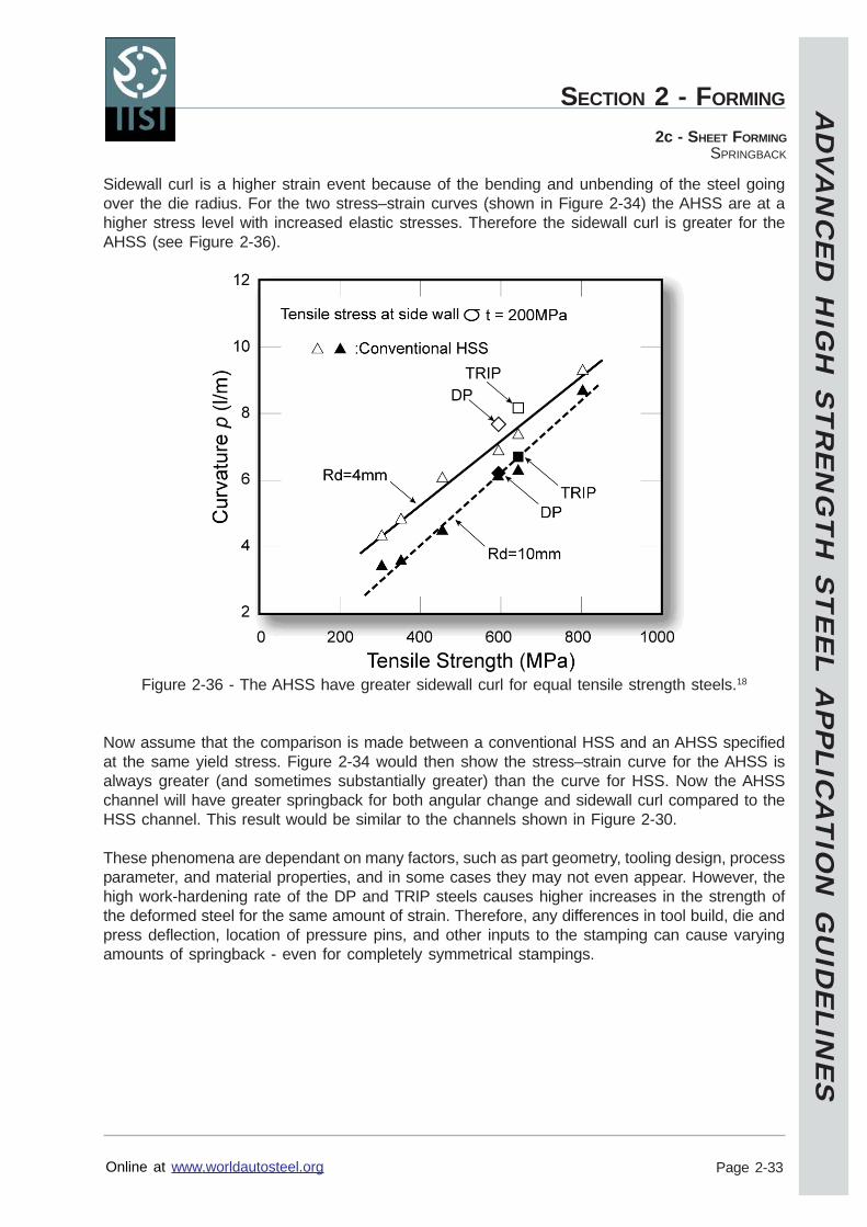
AD
VA
NC
ED
HIG
H S
TR
EN
GT
H S
TE
EL A
PP
LICA
TIO
N G
UID
ELIN
ES
Online at www.worldautosteel.org
SECTION 2 - FORMING
Page 2-33
2c - SHEET FORMINGSPRINGBACK
Sidewall curl is a higher strain event because of the bending and unbending of the steel goingover the die radius. For the two stress–strain curves (shown in Figure 2-34) the AHSS are at ahigher stress level with increased elastic stresses. Therefore the sidewall curl is greater for theAHSS (see Figure 2-36).
Figure 2-36 - The AHSS have greater sidewall curl for equal tensile strength steels.18
Now assume that the comparison is made between a conventional HSS and an AHSS specifiedat the same yield stress. Figure 2-34 would then show the stress–strain curve for the AHSS isalways greater (and sometimes substantially greater) than the curve for HSS. Now the AHSSchannel will have greater springback for both angular change and sidewall curl compared to theHSS channel. This result would be similar to the channels shown in Figure 2-30.
These phenomena are dependant on many factors, such as part geometry, tooling design, processparameter, and material properties, and in some cases they may not even appear. However, thehigh work-hardening rate of the DP and TRIP steels causes higher increases in the strength ofthe deformed steel for the same amount of strain. Therefore, any differences in tool build, die andpress deflection, location of pressure pins, and other inputs to the stamping can cause varyingamounts of springback - even for completely symmetrical stampings.
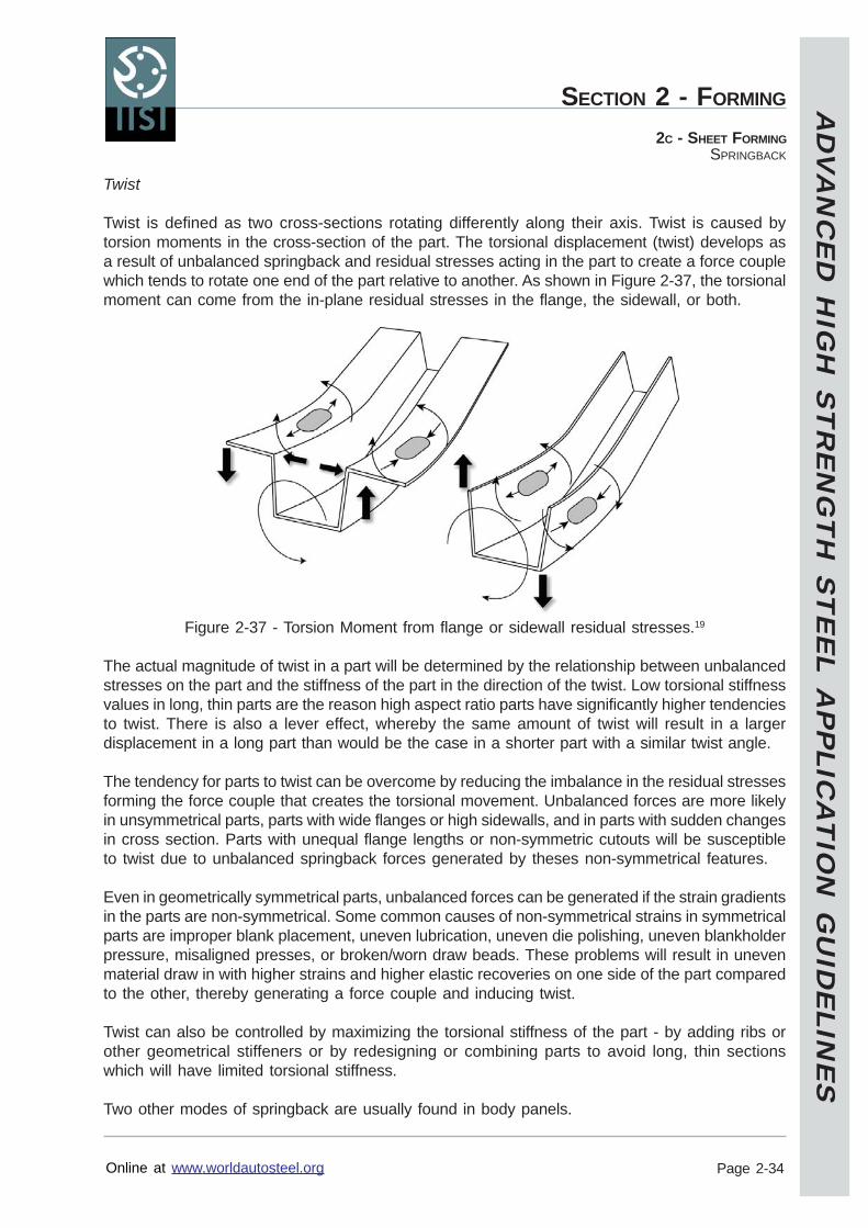
AD
VA
NC
ED
HIG
H S
TR
EN
GT
H S
TE
EL A
PP
LICA
TIO
N G
UID
ELIN
ES
Online at www.worldautosteel.org
SECTION 2 - FORMING
Page 2-34
2C - SHEET FORMINGSPRINGBACK
Twist
Twist is defined as two cross-sections rotating differently along their axis. Twist is caused bytorsion moments in the cross-section of the part. The torsional displacement (twist) develops asa result of unbalanced springback and residual stresses acting in the part to create a force couplewhich tends to rotate one end of the part relative to another. As shown in Figure 2-37, the torsionalmoment can come from the in-plane residual stresses in the flange, the sidewall, or both.
Figure 2-37 - Torsion Moment from flange or sidewall residual stresses.19
The actual magnitude of twist in a part will be determined by the relationship between unbalancedstresses on the part and the stiffness of the part in the direction of the twist. Low torsional stiffnessvalues in long, thin parts are the reason high aspect ratio parts have significantly higher tendenciesto twist. There is also a lever effect, whereby the same amount of twist will result in a largerdisplacement in a long part than would be the case in a shorter part with a similar twist angle.
The tendency for parts to twist can be overcome by reducing the imbalance in the residual stressesforming the force couple that creates the torsional movement. Unbalanced forces are more likelyin unsymmetrical parts, parts with wide flanges or high sidewalls, and in parts with sudden changesin cross section. Parts with unequal flange lengths or non-symmetric cutouts will be susceptibleto twist due to unbalanced springback forces generated by theses non-symmetrical features.
Even in geometrically symmetrical parts, unbalanced forces can be generated if the strain gradientsin the parts are non-symmetrical. Some common causes of non-symmetrical strains in symmetricalparts are improper blank placement, uneven lubrication, uneven die polishing, uneven blankholderpressure, misaligned presses, or broken/worn draw beads. These problems will result in unevenmaterial draw in with higher strains and higher elastic recoveries on one side of the part comparedto the other, thereby generating a force couple and inducing twist.
Twist can also be controlled by maximizing the torsional stiffness of the part - by adding ribs orother geometrical stiffeners or by redesigning or combining parts to avoid long, thin sectionswhich will have limited torsional stiffness.
Two other modes of springback are usually found in body panels.
AD
VA
NC
ED
HIG
H S
TR
EN
GT
H S
TE
EL A
PP
LICA
TIO
N G
UID
ELIN
ES
Online at www.worldautosteel.org
SECTION 2 - FORMING
Page 2-35
2c - SHEET FORMINGSPRINGBACK
Global Shape Change
Global shape changes, such as reduced curvature when unloading the panel in the die, areusually corrected by springback compensation measures. The key problem is springback variationduring the run of the stamping and during die transition. One study showed that the greatestglobal shape (dimensional) changes were generated during die transition.20
Surface Disturbances
Springback defects develop from local reaction to residual stress patterns within the body of thestamping. Common examples are high and low spots, oil canning, and other local deformationsthat form to balance total residual stresses to their lowest value.
AD
VA
NC
ED
HIG
H S
TR
EN
GT
H S
TE
EL A
PP
LICA
TIO
N G
UID
ELIN
ES
Online at www.worldautosteel.org
SECTION 2 - FORMING
Page 2-36
2c - SHEET FORMINGSPRINGBACK
Springback Correction for AHSS - Part Design
Successful application of any material requires close coordination of part design and themanufacturing process. Consult manufacturing process engineers when designing AHSSparts to understand the limitations/advantages of the material and the proper formingprocess to be employed.
Design structural frames (such as rails and crossbars) as open-end channels to permitforming operations rather than draw die processes. AHSS stampings requiring drawoperations (closed ends) are limited to a reduced depth of draw. Half the draw depthpermitted for AKDQ is the rule of thumb for AHSS such as DP 350/600. Less complex,open-ended stamped channels are less limited in depth.
Design AHSS channel shaped part depth as consistent as possible to avoid formingdistortions.
Springback computer simulations should be used whenever possible to predict the trendof springback and to test the effectiveness of solutions.
Design the part and tool in such a way that springback is desensitized to variations inmaterial, gauge, tools and forming processes (a robust system and process) and that theeffects of springback are minimized rather than attempt to compensate for it.
Design the punch radius as sharp as formability and product/style allow. Small bend radii(<2t) will decrease the springback angle and variation (see Figure 2-38). However, stretchbending will be more difficult as yield strength increases. In addition, sharp radii contributeto excessive thinning.
Figure 2-38 - Angular changes increased byYS and bend radius to sheet thickness ratio.21
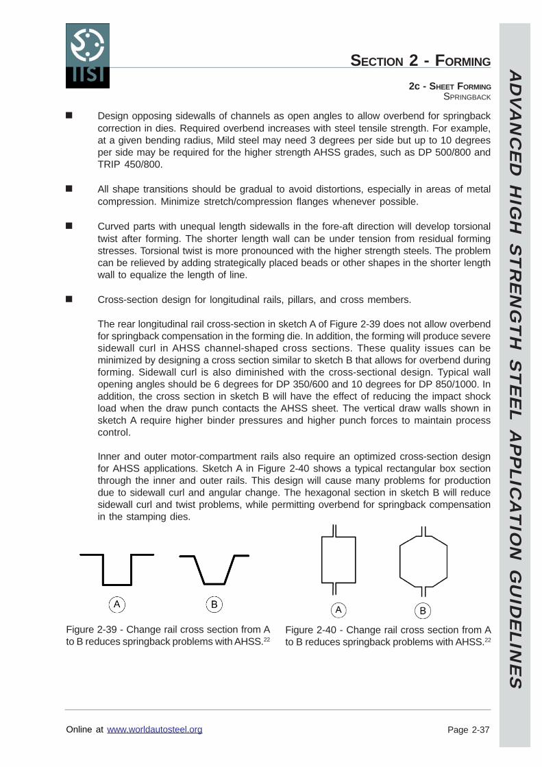
AD
VA
NC
ED
HIG
H S
TR
EN
GT
H S
TE
EL A
PP
LICA
TIO
N G
UID
ELIN
ES
Online at www.worldautosteel.org
SECTION 2 - FORMING
Page 2-37
2c - SHEET FORMINGSPRINGBACK
Design opposing sidewalls of channels as open angles to allow overbend for springbackcorrection in dies. Required overbend increases with steel tensile strength. For example,at a given bending radius, Mild steel may need 3 degrees per side but up to 10 degreesper side may be required for the higher strength AHSS grades, such as DP 500/800 andTRIP 450/800.
All shape transitions should be gradual to avoid distortions, especially in areas of metalcompression. Minimize stretch/compression flanges whenever possible.
Curved parts with unequal length sidewalls in the fore-aft direction will develop torsionaltwist after forming. The shorter length wall can be under tension from residual formingstresses. Torsional twist is more pronounced with the higher strength steels. The problemcan be relieved by adding strategically placed beads or other shapes in the shorter lengthwall to equalize the length of line.
Cross-section design for longitudinal rails, pillars, and cross members.
The rear longitudinal rail cross-section in sketch A of Figure 2-39 does not allow overbendfor springback compensation in the forming die. In addition, the forming will produce severesidewall curl in AHSS channel-shaped cross sections. These quality issues can beminimized by designing a cross section similar to sketch B that allows for overbend duringforming. Sidewall curl is also diminished with the cross-sectional design. Typical wallopening angles should be 6 degrees for DP 350/600 and 10 degrees for DP 850/1000. Inaddition, the cross section in sketch B will have the effect of reducing the impact shockload when the draw punch contacts the AHSS sheet. The vertical draw walls shown insketch A require higher binder pressures and higher punch forces to maintain processcontrol.
Inner and outer motor-compartment rails also require an optimized cross-section designfor AHSS applications. Sketch A in Figure 2-40 shows a typical rectangular box sectionthrough the inner and outer rails. This design will cause many problems for productiondue to sidewall curl and angular change. The hexagonal section in sketch B will reducesidewall curl and twist problems, while permitting overbend for springback compensationin the stamping dies.
Figure 2-39 - Change rail cross section from Ato B reduces springback problems with AHSS.22
Figure 2-40 - Change rail cross section from Ato B reduces springback problems with AHSS.22
AD
VA
NC
ED
HIG
H S
TR
EN
GT
H S
TE
EL A
PP
LICA
TIO
N G
UID
ELIN
ES
Online at www.worldautosteel.org
SECTION 2 - FORMING
Page 2-38
2c - SHEET FORMINGSPRINGBACK
Springback Correction for AHSS - Process Design
General Guidelines
Multiple stage forming processes may be desirable or even required, depending on thepart shape. Utilize secondary operations to return a sprung shape back to part datum.Care must be taken though to ensure that any subsequent operation does not exceed thework hardening limit of the worked material. Use multi-stage computerized forming processdevelopment to confirm strain and work hardening levels. Try to fold the sheet metal overa radius instead drawing or stretching over a radius.
Angular Change
Apply in-plane tension after bending (post-stretch). This can be done by designing aprocess with bending forming first and stretching later or by locking the binder with movablebeads at the end of the stroke and applying additional stretch (see Figure 2-41). Sidewallcurl also can be minimized and made more stable by post-stretch. Note that these post-stretch forming operations normally require significantly higher forming force to be effectivesince the sidewalls have significant work hardening resulting from the forming operation.
Figure 2-41 - A post-stretch greater than 1% eliminatesthe increase in springback as the yield stress increases.23
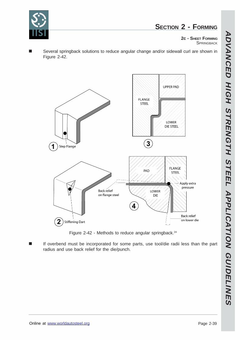
AD
VA
NC
ED
HIG
H S
TR
EN
GT
H S
TE
EL A
PP
LICA
TIO
N G
UID
ELIN
ES
Online at www.worldautosteel.org
SECTION 2 - FORMING
Page 2-39
2c - SHEET FORMINGSPRINGBACK
Several springback solutions to reduce angular change and/or sidewall curl are shown inFigure 2-42.
Figure 2-42 - Methods to reduce angular springback.24
If overbend must be incorporated for some parts, use tool/die radii less than the partradius and use back relief for the die/punch.
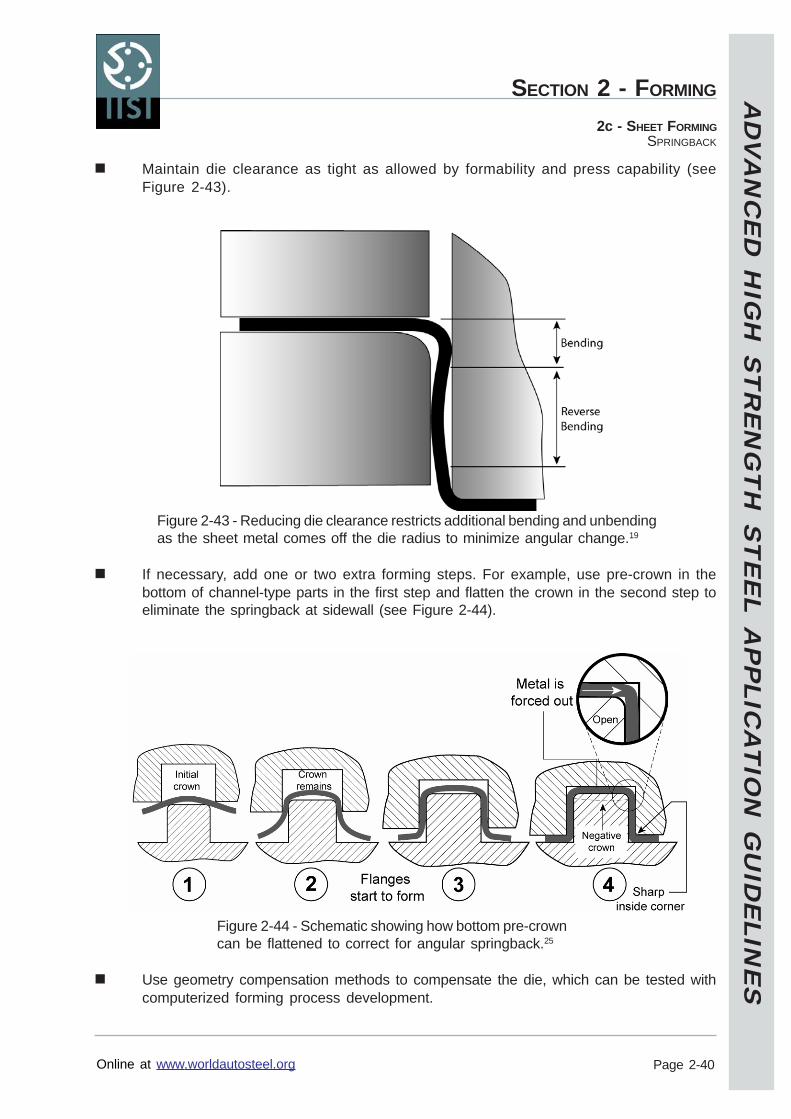
AD
VA
NC
ED
HIG
H S
TR
EN
GT
H S
TE
EL A
PP
LICA
TIO
N G
UID
ELIN
ES
Online at www.worldautosteel.org
SECTION 2 - FORMING
Page 2-40
2c - SHEET FORMINGSPRINGBACK
Maintain die clearance as tight as allowed by formability and press capability (seeFigure 2-43).
Figure 2-43 - Reducing die clearance restricts additional bending and unbendingas the sheet metal comes off the die radius to minimize angular change.19
If necessary, add one or two extra forming steps. For example, use pre-crown in thebottom of channel-type parts in the first step and flatten the crown in the second step toeliminate the springback at sidewall (see Figure 2-44).
Figure 2-44 - Schematic showing how bottom pre-crowncan be flattened to correct for angular springback.25
Use geometry compensation methods to compensate the die, which can be tested withcomputerized forming process development.
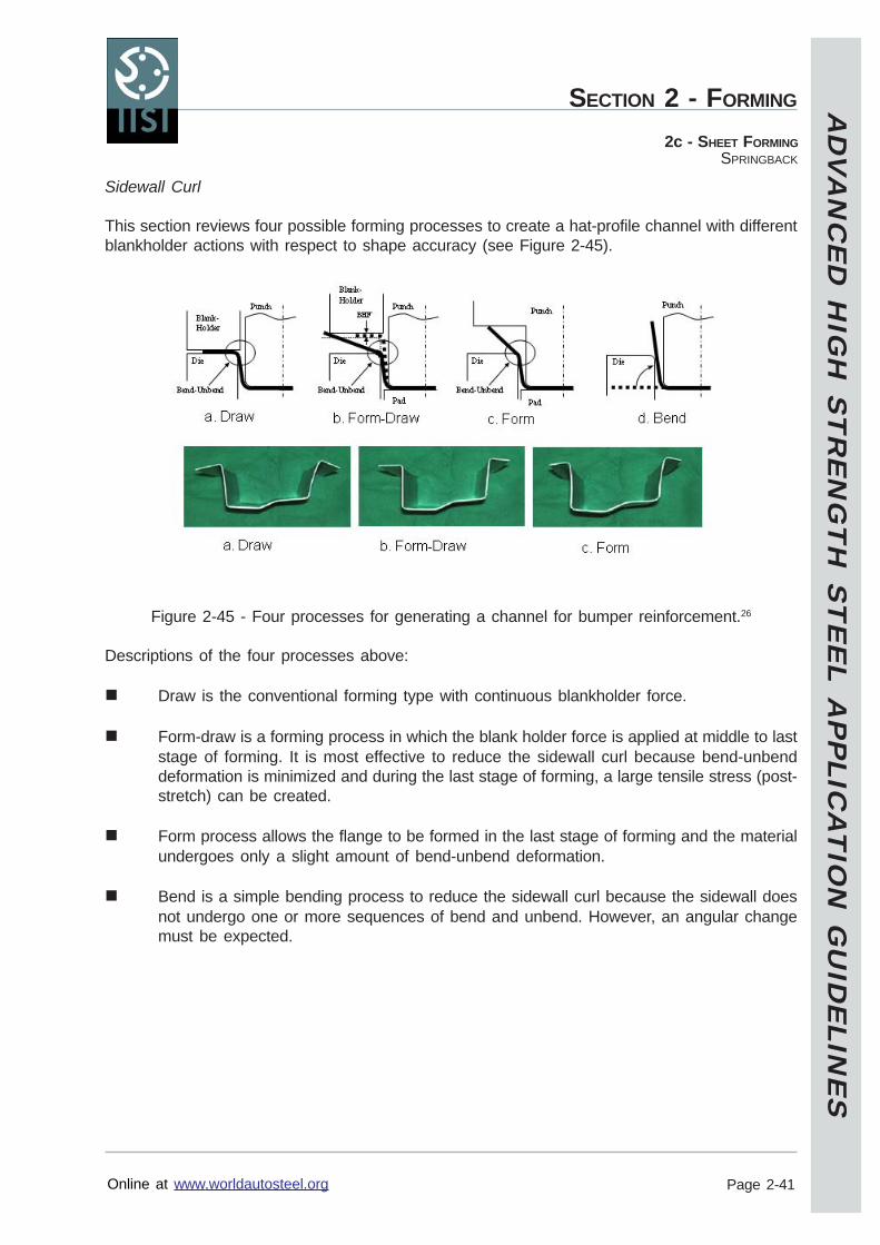
AD
VA
NC
ED
HIG
H S
TR
EN
GT
H S
TE
EL A
PP
LICA
TIO
N G
UID
ELIN
ES
Online at www.worldautosteel.org
SECTION 2 - FORMING
Page 2-41
2c - SHEET FORMINGSPRINGBACK
Sidewall Curl
This section reviews four possible forming processes to create a hat-profile channel with differentblankholder actions with respect to shape accuracy (see Figure 2-45).
Figure 2-45 - Four processes for generating a channel for bumper reinforcement.26
Descriptions of the four processes above:
Draw is the conventional forming type with continuous blankholder force.
Form-draw is a forming process in which the blank holder force is applied at middle to laststage of forming. It is most effective to reduce the sidewall curl because bend-unbenddeformation is minimized and during the last stage of forming, a large tensile stress (post-stretch) can be created.
Form process allows the flange to be formed in the last stage of forming and the materialundergoes only a slight amount of bend-unbend deformation.
Bend is a simple bending process to reduce the sidewall curl because the sidewall doesnot undergo one or more sequences of bend and unbend. However, an angular changemust be expected.
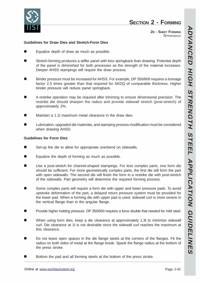
AD
VA
NC
ED
HIG
H S
TR
EN
GT
H S
TE
EL A
PP
LICA
TIO
N G
UID
ELIN
ES
Online at www.worldautosteel.org
SECTION 2 - FORMING
Page 2-42
2c - SHEET FORMINGSPRINGBACK
Guidelines for Draw Dies and Stretch-Form Dies
Equalize depth of draw as much as possible.
Stretch-forming produces a stiffer panel with less springback than drawing. Potential depthof the panel is diminished for both processes as the strength of the material increases.Deeper AHSS stampings will require the draw process.
Binder pressure must be increased for AHSS. For example, DP 350/600 requires a tonnagefactor 2.5 times greater than that required for AKDQ of comparable thickness. Higherbinder pressure will reduce panel springback.
A restrike operation may be required after trimming to ensure dimensional precision. Therestrike die should sharpen the radius and provide sidewall stretch (post-stretch) ofapproximately 2%.
Maintain a 1.1t maximum metal clearance in the draw dies.
Lubrication, upgraded die materials, and stamping process modification must be consideredwhen drawing AHSS.
Guidelines for Form Dies
Set-up the die to allow for appropriate overbend on sidewalls.
Equalize the depth of forming as much as possible.
Use a post-stretch for channel-shaped stampings. For less complex parts, one form dieshould be sufficient. For more geometrically complex parts, the first die will form the partwith open sidewalls. The second die will finish the form in a restrike die with post-stretchof the sidewalls. Part geometry will determine the required forming process.
Some complex parts will require a form die with upper and lower pressure pads. To avoidupstroke deformation of the part, a delayed return pressure system must be provided forthe lower pad. When a forming die with upper pad is used, sidewall curl is more severe inthe vertical flange than in the angular flange.
Provide higher holding pressure. DP 350/600 requires a force double that needed for mild steel.
When using form dies, keep a die clearance at approximately 1.3t to minimize sidewallcurl. Die clearance at 1t is not desirable since the sidewall curl reaches the maximum atthis clearance.
Do not leave open spaces in the die flange steels at the corners of the flanges. Fit theradius on both sides of metal at the flange break. Spank the flange radius at the bottom ofthe press stroke.
Bottom the pad and all forming steels at the bottom of the press stroke.
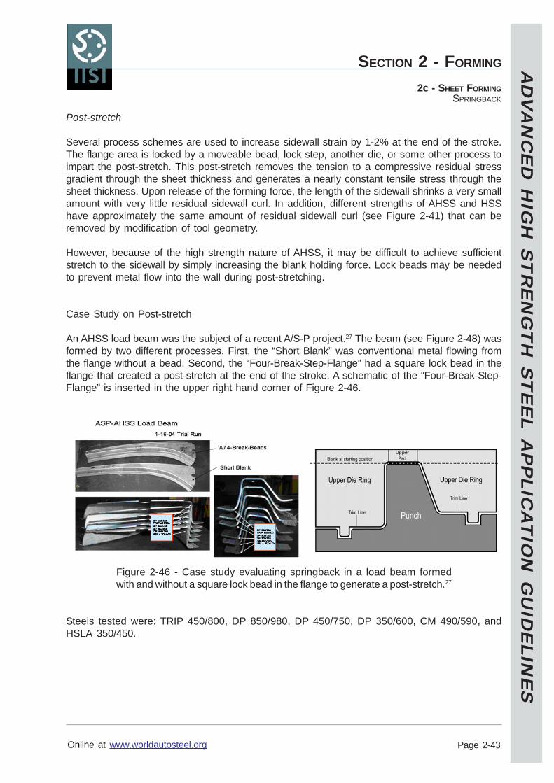
AD
VA
NC
ED
HIG
H S
TR
EN
GT
H S
TE
EL A
PP
LICA
TIO
N G
UID
ELIN
ES
Online at www.worldautosteel.org
SECTION 2 - FORMING
Page 2-43
2c - SHEET FORMINGSPRINGBACK
Post-stretch
Several process schemes are used to increase sidewall strain by 1-2% at the end of the stroke.The flange area is locked by a moveable bead, lock step, another die, or some other process toimpart the post-stretch. This post-stretch removes the tension to a compressive residual stressgradient through the sheet thickness and generates a nearly constant tensile stress through thesheet thickness. Upon release of the forming force, the length of the sidewall shrinks a very smallamount with very little residual sidewall curl. In addition, different strengths of AHSS and HSShave approximately the same amount of residual sidewall curl (see Figure 2-41) that can beremoved by modification of tool geometry.
However, because of the high strength nature of AHSS, it may be difficult to achieve sufficientstretch to the sidewall by simply increasing the blank holding force. Lock beads may be neededto prevent metal flow into the wall during post-stretching.
Case Study on Post-stretch
An AHSS load beam was the subject of a recent A/S-P project.27 The beam (see Figure 2-48) wasformed by two different processes. First, the “Short Blank” was conventional metal flowing fromthe flange without a bead. Second, the “Four-Break-Step-Flange” had a square lock bead in theflange that created a post-stretch at the end of the stroke. A schematic of the “Four-Break-Step-Flange” is inserted in the upper right hand corner of Figure 2-46.
Figure 2-46 - Case study evaluating springback in a load beam formedwith and without a square lock bead in the flange to generate a post-stretch.27
Steels tested were: TRIP 450/800, DP 850/980, DP 450/750, DP 350/600, CM 490/590, andHSLA 350/450.
AD
VA
NC
ED
HIG
H S
TR
EN
GT
H S
TE
EL A
PP
LICA
TIO
N G
UID
ELIN
ES
Online at www.worldautosteel.org
SECTION 2 - FORMING
Page 2-44
2c - SHEET FORMINGSPRINGBACK
The following conclusions were obtained from the springback data analysis:1. The twist angles for 4-Break-Step-Flange and the Short Blank forming processes are in
reversed directions. The amount of twist angle is smaller before flange trimming for the 4-Break-Step-Flange forming process. The twist angles are smaller for the Short Blankforming after flange trimming.
2. The twist angle of the Short Blank forming increases with the material tensile strength. Noconsistent strength dependency was observed for the 4-Break-Step-Flange formingprocess.
3. The sidewall curl is very small.4. The evaluation of the dimensionless springback indicates that:
a) The Average Dimensionless Springback increases almost linearly with the materialtensile strength for the Short Blank forming.
b) The material tensile strength does not have much effect on the amount of springbackfor the 4-Break-Step-Forming process.
c) The amount of springback increases after trimming.d) The springback of the 4-Break-Step-Flange forming process is about one third of
that of the Short Blank forming.e) For the Short Blank forming, DP 350/600 has much larger springback than CM
490/590. TRIP 450/800 has slightly lower springback than DP 450/750.
The study showed the effectiveness of the square lock bead to create a post-stretch operation inthe binder (flange) area during forming to maintain constant springback independent of steeltensile strength. This translates into a more robust process.
Twist and Edge Line Warping
Conventional guidelines for normal steels can also be applied to AHSS to avoid asymmetrythat accentuates the possibility for part twist. Consequently, the greater springback exhibitedby AHSS means extra caution should taken to ensure symmetry is maintained as much aspossible.
Avoid sudden change of cross-section shape.
Equalize the forming depth where possible.
Add darts and geometric stiffeners.
Optimize blank shape to balance deformation.
Trim process or order can be optimized to reduce twisting.
Minimize the flange length, normal to the part.
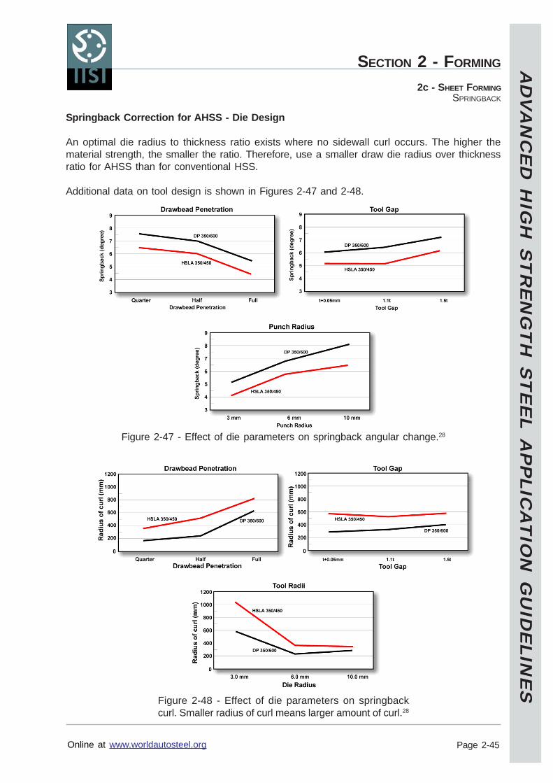
AD
VA
NC
ED
HIG
H S
TR
EN
GT
H S
TE
EL A
PP
LICA
TIO
N G
UID
ELIN
ES
Online at www.worldautosteel.org
SECTION 2 - FORMING
Page 2-45
2c - SHEET FORMINGSPRINGBACK
Springback Correction for AHSS - Die Design
An optimal die radius to thickness ratio exists where no sidewall curl occurs. The higher thematerial strength, the smaller the ratio. Therefore, use a smaller draw die radius over thicknessratio for AHSS than for conventional HSS.
Additional data on tool design is shown in Figures 2-47 and 2-48.
Figure 2-47 - Effect of die parameters on springback angular change.28
Figure 2-48 - Effect of die parameters on springbackcurl. Smaller radius of curl means larger amount of curl.28
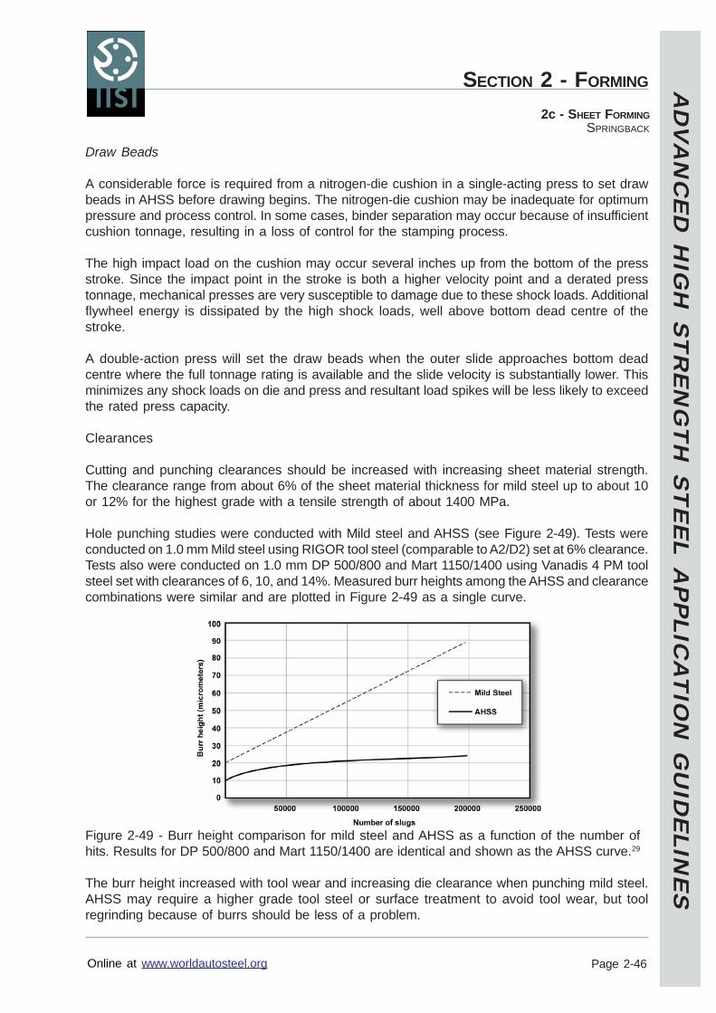
AD
VA
NC
ED
HIG
H S
TR
EN
GT
H S
TE
EL A
PP
LICA
TIO
N G
UID
ELIN
ES
Online at www.worldautosteel.org
SECTION 2 - FORMING
Page 2-46
2c - SHEET FORMINGSPRINGBACK
Draw Beads
A considerable force is required from a nitrogen-die cushion in a single-acting press to set drawbeads in AHSS before drawing begins. The nitrogen-die cushion may be inadequate for optimumpressure and process control. In some cases, binder separation may occur because of insufficientcushion tonnage, resulting in a loss of control for the stamping process.
The high impact load on the cushion may occur several inches up from the bottom of the pressstroke. Since the impact point in the stroke is both a higher velocity point and a derated presstonnage, mechanical presses are very susceptible to damage due to these shock loads. Additionalflywheel energy is dissipated by the high shock loads, well above bottom dead centre of thestroke.
A double-action press will set the draw beads when the outer slide approaches bottom deadcentre where the full tonnage rating is available and the slide velocity is substantially lower. Thisminimizes any shock loads on die and press and resultant load spikes will be less likely to exceedthe rated press capacity.
Clearances
Cutting and punching clearances should be increased with increasing sheet material strength.The clearance range from about 6% of the sheet material thickness for mild steel up to about 10or 12% for the highest grade with a tensile strength of about 1400 MPa.
Hole punching studies were conducted with Mild steel and AHSS (see Figure 2-49). Tests wereconducted on 1.0 mm Mild steel using RIGOR tool steel (comparable to A2/D2) set at 6% clearance.Tests also were conducted on 1.0 mm DP 500/800 and Mart 1150/1400 using Vanadis 4 PM toolsteel set with clearances of 6, 10, and 14%. Measured burr heights among the AHSS and clearancecombinations were similar and are plotted in Figure 2-49 as a single curve.
Figure 2-49 - Burr height comparison for mild steel and AHSS as a function of the number ofhits. Results for DP 500/800 and Mart 1150/1400 are identical and shown as the AHSS curve.29
The burr height increased with tool wear and increasing die clearance when punching mild steel.AHSS may require a higher grade tool steel or surface treatment to avoid tool wear, but toolregrinding because of burrs should be less of a problem.
AD
VA
NC
ED
HIG
H S
TR
EN
GT
H S
TE
EL A
PP
LICA
TIO
N G
UID
ELIN
ES
Online at www.worldautosteel.org
SECTION 2 - FORMING
Page 2-47
2c - SHEET FORMINGSPRINGBACK
Key Points
Angular change and sidewall curl escalate with increasing as-formed yield strength anddecrease with increasing material thickness.DP steels exhibit more springback and curl than conventional HSLA steels. The springbackbehaviours of TRIP steels are between DP and HSLA steels.The sidewall curl appears to be more sensitive to the material and set-up in a channeldraw test.The angular change decreased with smaller tooling radii and tool gap, but sidewall curlshowed mixed results for smaller tooling and tool gap. Both angular change and sidewallcurl were reduced with a larger drawbead restraining force.Numerous process modifications are available to remove (or at least minimize and stabilize)the different modes of springback found in channels and similar configurations.
AD
VA
NC
ED
HIG
H S
TR
EN
GT
H S
TE
EL A
PP
LICA
TIO
N G
UID
ELIN
ES
Online at www.worldautosteel.org
SECTION 2 - FORMING
Page 2-48
2c - SHEET FORMINGBLANKING, SHEARING, AND TRIM OPERATIONS
Blanking, Shearing, and Trim Operations
Formability of Cut Edges
AHSS exhibit high work hardening rates, resulting in improved forming capabilities compared toconventional HSS. However, the same high work hardening creates higher strength and hardnessin sheared or punched edges. In addition, laser cutting samples will also lead to highly localizedstrength and hardness increases in the cut edge. In general, AHSS can be more sensitive toedge condition because of this higher strength. Therefore, it is important to obtain a good qualityedge during the cutting operation. With a good edge, both sheared and laser cut processes canbe used to provide adequate formability.To avoid unexpected problems during a programme launch, it is advised that production intenttooling be used as early in the development as possible. For example, switching to a shearededge from a laser-cut edge may lead to problems if the lower ductility, usually associated with asheared edge, is not accounted for during development.
Key Points
Clearances for blanking and shearing should increase as the strength of the materialincreases.Burr height increases with tool wear and increasing die clearances for shearing mild steel,but AHSS tends to maintain a constant burr height. This means extended intervals betweentool sharpening may be applicable to AHSS parts.Laser cut blanks used during early tool tryout may not represent normal blanking, shearing,and punching quality. Production intent tooling should be used as early as possible in thedevelopment stage.
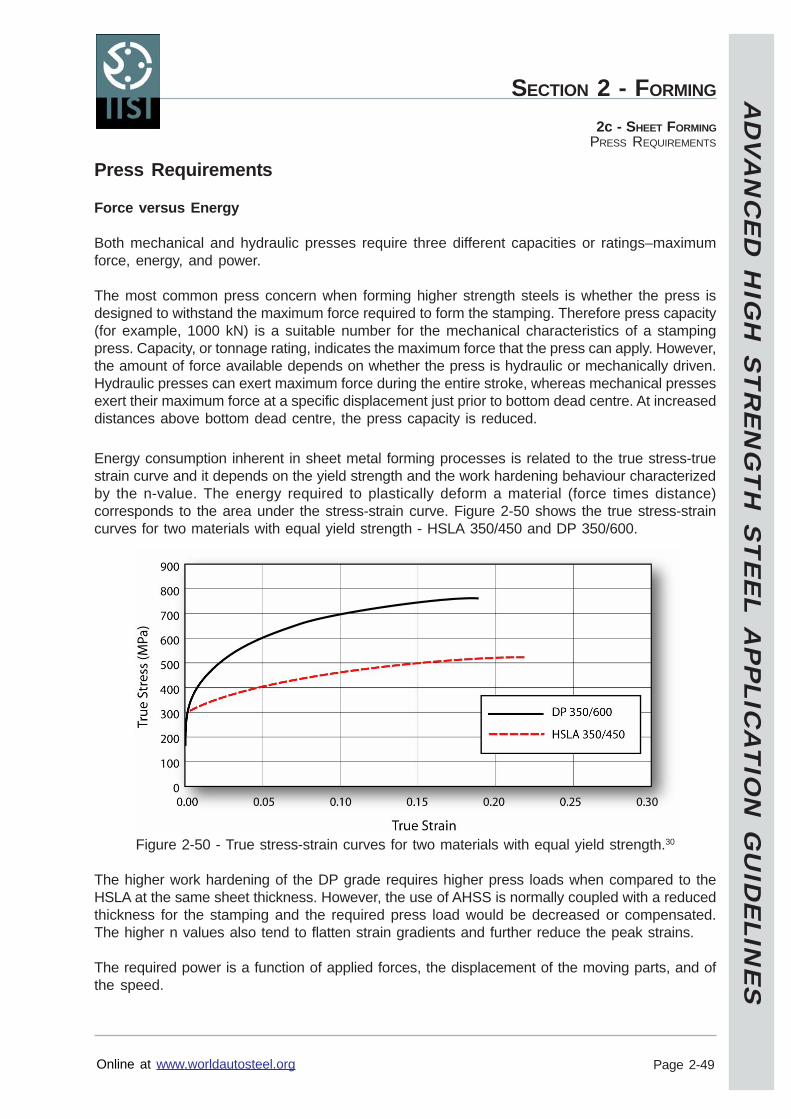
AD
VA
NC
ED
HIG
H S
TR
EN
GT
H S
TE
EL A
PP
LICA
TIO
N G
UID
ELIN
ES
Online at www.worldautosteel.org
SECTION 2 - FORMING
Page 2-49
2c - SHEET FORMINGPRESS REQUIREMENTS
Press Requirements
Force versus Energy
Both mechanical and hydraulic presses require three different capacities or ratings–maximumforce, energy, and power.
The most common press concern when forming higher strength steels is whether the press isdesigned to withstand the maximum force required to form the stamping. Therefore press capacity(for example, 1000 kN) is a suitable number for the mechanical characteristics of a stampingpress. Capacity, or tonnage rating, indicates the maximum force that the press can apply. However,the amount of force available depends on whether the press is hydraulic or mechanically driven.Hydraulic presses can exert maximum force during the entire stroke, whereas mechanical pressesexert their maximum force at a specific displacement just prior to bottom dead centre. At increaseddistances above bottom dead centre, the press capacity is reduced.
Energy consumption inherent in sheet metal forming processes is related to the true stress-truestrain curve and it depends on the yield strength and the work hardening behaviour characterizedby the n-value. The energy required to plastically deform a material (force times distance)corresponds to the area under the stress-strain curve. Figure 2-50 shows the true stress-straincurves for two materials with equal yield strength - HSLA 350/450 and DP 350/600.
Figure 2-50 - True stress-strain curves for two materials with equal yield strength.30
The higher work hardening of the DP grade requires higher press loads when compared to theHSLA at the same sheet thickness. However, the use of AHSS is normally coupled with a reducedthickness for the stamping and the required press load would be decreased or compensated.The higher n values also tend to flatten strain gradients and further reduce the peak strains.
The required power is a function of applied forces, the displacement of the moving parts, and ofthe speed.
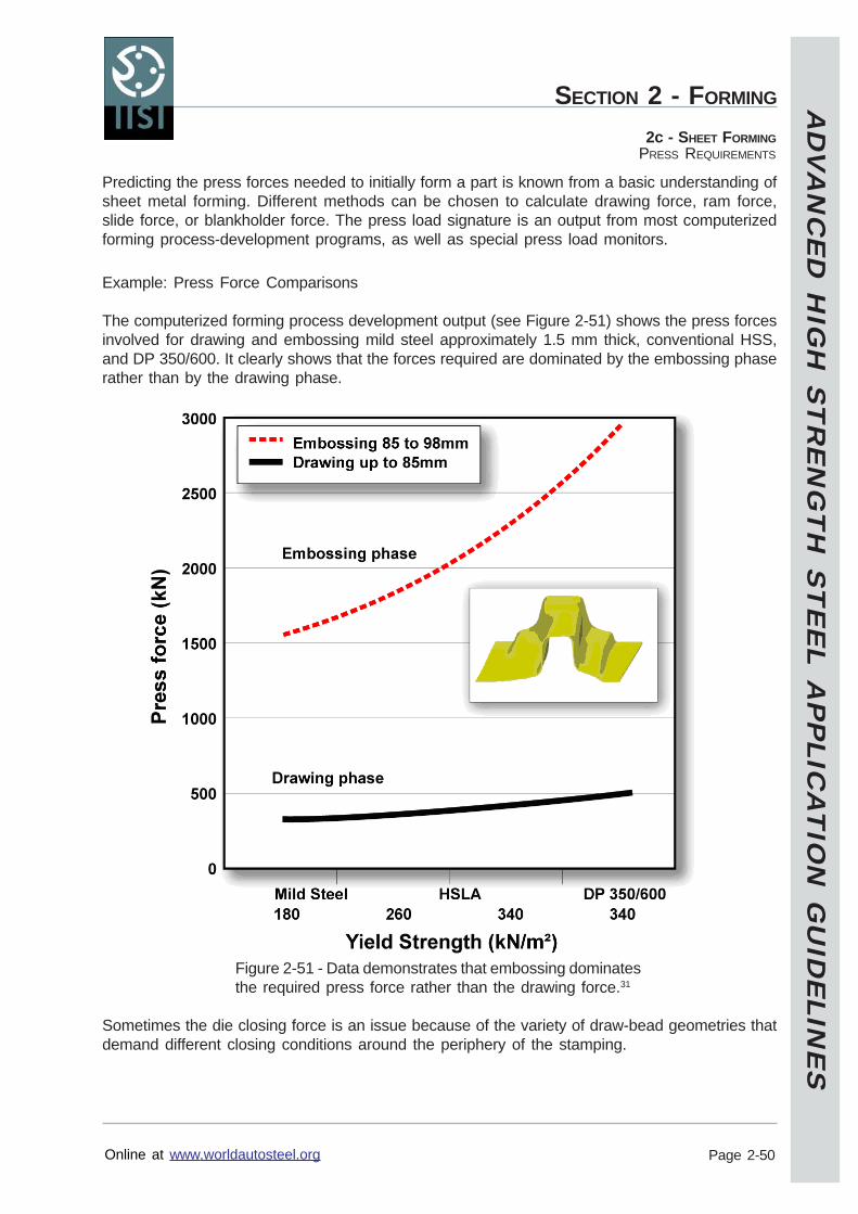
AD
VA
NC
ED
HIG
H S
TR
EN
GT
H S
TE
EL A
PP
LICA
TIO
N G
UID
ELIN
ES
Online at www.worldautosteel.org
SECTION 2 - FORMING
Page 2-50
2c - SHEET FORMINGPRESS REQUIREMENTS
Predicting the press forces needed to initially form a part is known from a basic understanding ofsheet metal forming. Different methods can be chosen to calculate drawing force, ram force,slide force, or blankholder force. The press load signature is an output from most computerizedforming process-development programs, as well as special press load monitors.
Example: Press Force Comparisons
The computerized forming process development output (see Figure 2-51) shows the press forcesinvolved for drawing and embossing mild steel approximately 1.5 mm thick, conventional HSS,and DP 350/600. It clearly shows that the forces required are dominated by the embossing phaserather than by the drawing phase.
Figure 2-51 - Data demonstrates that embossing dominatesthe required press force rather than the drawing force.31
Sometimes the die closing force is an issue because of the variety of draw-bead geometries thatdemand different closing conditions around the periphery of the stamping.
AD
VA
NC
ED
HIG
H S
TR
EN
GT
H S
TE
EL A
PP
LICA
TIO
N G
UID
ELIN
ES
Online at www.worldautosteel.org
SECTION 2 - FORMING
Page 2-51
2c - SHEET FORMINGPRESS REQUIREMENTS
Example: Press Energy Comparisons
A similar analysis (see Figure 2-52) shows the press energy required to draw and emboss thesame steels shown in Figure 2-51. The energy required is also dominated by the embossingphase rather than by the drawing phase, although the punch travel for embossing is only afraction of the drawing depth.
Figure 2-52 - Data showing the energy required to embossa component is grater than for the drawing component.31
AD
VA
NC
ED
HIG
H S
TR
EN
GT
H S
TE
EL A
PP
LICA
TIO
N G
UID
ELIN
ES
Online at www.worldautosteel.org
SECTION 2 - FORMING
Page 2-52
2c - SHEET FORMINGPRESS REQUIREMENTS
Prediction of Press Forces Using Simulative Tests
Relative press forces from Marciniak stretching tests showed AHSS grades require higher punchforces in stretch forming operations (see Figure 2-53). However, applying the stretch formingmode for CP grades is not common due to the lower stretchability of CP grades.
Figure 2-53 - Punch forces from Marciniak cup-stretchforming tests for AHSS and conventional steel types.31
Extrapolation From Existing Production Data
Relationships between thickness and UTS can be used for a quick extrapolation calculation ofpress loads, as long as simple geometries are investigated. Figure 2-54 shows the measuredpress loads for the production of a cross member with a simple hat-profile made of HSLA 350/450 and DP 300/500 steels of the same thickness.
Figure 2-54 - Measured press load for a Hat-Profile Cross Member.16
AD
VA
NC
ED
HIG
H S
TR
EN
GT
H S
TE
EL A
PP
LICA
TIO
N G
UID
ELIN
ES
Online at www.worldautosteel.org
SECTION 2 - FORMING
Page 2-53
2c - SHEET FORMINGPRESS REQUIREMENTS
Using the following equation, the press load F2 for DP 300/500 was estimated from the knownpress load F1 from HSLA 350/450.32
F2 is proportional to F1 * (t2/t1) * (Rm2/Rm1)
Where: F1 Old Drawing ForceF2 New Drawing Forcet1 Old Material Thicknesst2 New Material ThicknessRm1 Old Tensile StrengthRm2 New Tensile Strength
The data above compares the measured force and the predicted force for the DP 300/500 usingthe formula. A good correlation between measured and predicted drawing force was obtained.While good force estimations are possible using this extrapolation technique, the accuracy israther limited and often overstates the load. Therefore, the calculation should be viewed as anupper boundary.
Computerized Forming Process Development
Rules of thumb are useful to estimate press loads. A better evaluation of press loads, such asdraw force, embossment force, and blank holding force, can be obtained from computerizedtools. Many of the programs enable the user to specify all of the system inputs. This is especiallyimportant when forming AHSS because the high rate of work hardening has a major effect on thepress loads. In addition, instead of using a simple restraining force on blank movement, analysesof the physical draw beads must be calculated.
Another important input to any calculation is the assumption that the tools are rigid during forming,when in reality the tools deform elastically in operation. This discrepancy leads to a significantincrease in the determined press loads, especially when the punch is at home position. Hence,for a given part, the draw depth used for the determination of the calculated press load is animportant parameter. For example, if the nominal draw depth is applied, press loads may beoverestimated. The deflection (sometimes called breathing) of the dies is accentuated by thehigher work hardening of the AHSS.
Similarly, the structure, platens, bolsters, and other components of the press are assumed to becompletely rigid. This is not true and causes variation in press loads, especially when physicaltooling is moved from one press to another.
AD
VA
NC
ED
HIG
H S
TR
EN
GT
H S
TE
EL A
PP
LICA
TIO
N G
UID
ELIN
ES
Online at www.worldautosteel.org
SECTION 2 - FORMING
Page 2-54
2c - SHEET FORMINGPRESS REQUIREMENTS
If no proven procedure for computerized prediction is available, validation of the empiricalcalculations is recommended. Practical pressing tests should be used to determine the optimumparameter settings for the simulation. Under special situations, such as restrike operation, it ispossible that computerized analyses may not give a good estimation of the press loads. In thesecases, computerized tools can suggest forming trends for a given part and assist in developing amore favourable forming-process design.
Most structural components include design features to improve local stiffness. Features requiringembossing processes are mostly formed near the end of the ram cycle. Predicting forces neededfor such a process is mostly based on press shop experiences applicable to conventional steelgrades. To generate comparable numbers for AHSS grades, computerized forming processdevelopment is recommended.
Case Study for Press Energy
The following study is a computerized analysis of the energy required to form a cross memberwith a hat-profile and a bottom embossment at the end of the stroke (see Figure 2-55).
Figure 2-55 - Cross-section of a component having a longitudinal embossment to improve stiffness locally.31
Increasing energy is needed to continue punch travel. The complete required energy curves areshown in Figure 2-56 for mild steel, conventional HSLA steel, and DP steel. The three dots indicatethe start of the embossment formation at a punch movement of 85 mm.
Figure 2-56 - Computerized analysis showing the increase in energy needed to form the componentwith different steel grades. Forming the embossment begins at 85 mm of punch travel.31
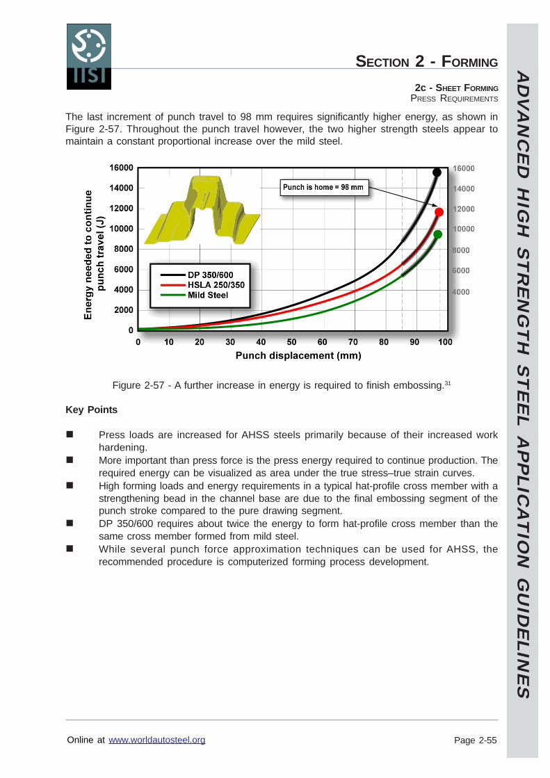
AD
VA
NC
ED
HIG
H S
TR
EN
GT
H S
TE
EL A
PP
LICA
TIO
N G
UID
ELIN
ES
Online at www.worldautosteel.org
SECTION 2 - FORMING
Page 2-55
2c - SHEET FORMINGPRESS REQUIREMENTS
The last increment of punch travel to 98 mm requires significantly higher energy, as shown inFigure 2-57. Throughout the punch travel however, the two higher strength steels appear tomaintain a constant proportional increase over the mild steel.
Figure 2-57 - A further increase in energy is required to finish embossing.31
Key Points
Press loads are increased for AHSS steels primarily because of their increased workhardening.More important than press force is the press energy required to continue production. Therequired energy can be visualized as area under the true stress–true strain curves.High forming loads and energy requirements in a typical hat-profile cross member with astrengthening bead in the channel base are due to the final embossing segment of thepunch stroke compared to the pure drawing segment.DP 350/600 requires about twice the energy to form hat-profile cross member than thesame cross member formed from mild steel.While several punch force approximation techniques can be used for AHSS, therecommended procedure is computerized forming process development.
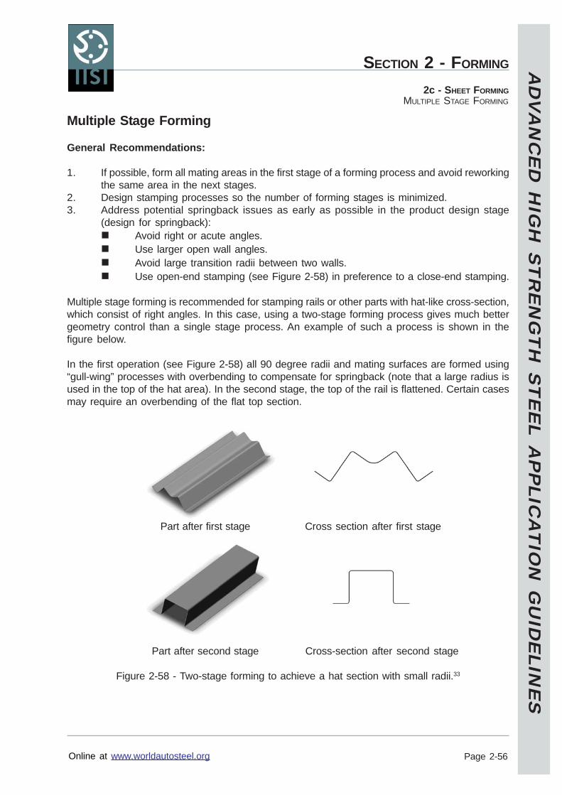
AD
VA
NC
ED
HIG
H S
TR
EN
GT
H S
TE
EL A
PP
LICA
TIO
N G
UID
ELIN
ES
Online at www.worldautosteel.org
SECTION 2 - FORMING
Page 2-56
2c - SHEET FORMINGMULTIPLE STAGE FORMING
Multiple Stage Forming
General Recommendations:
1. If possible, form all mating areas in the first stage of a forming process and avoid reworkingthe same area in the next stages.
2. Design stamping processes so the number of forming stages is minimized.3. Address potential springback issues as early as possible in the product design stage
(design for springback):Avoid right or acute angles.Use larger open wall angles.Avoid large transition radii between two walls.Use open-end stamping (see Figure 2-58) in preference to a close-end stamping.
Multiple stage forming is recommended for stamping rails or other parts with hat-like cross-section,which consist of right angles. In this case, using a two-stage forming process gives much bettergeometry control than a single stage process. An example of such a process is shown in thefigure below.
In the first operation (see Figure 2-58) all 90 degree radii and mating surfaces are formed using“gull-wing” processes with overbending to compensate for springback (note that a large radius isused in the top of the hat area). In the second stage, the top of the rail is flattened. Certain casesmay require an overbending of the flat top section.
Part after first stage Cross section after first stage
Part after second stage Cross-section after second stage
Figure 2-58 - Two-stage forming to achieve a hat section with small radii.33
AD
VA
NC
ED
HIG
H S
TR
EN
GT
H S
TE
EL A
PP
LICA
TIO
N G
UID
ELIN
ES
Online at www.worldautosteel.org
SECTION 2 - FORMING
Page 2-57
2c - SHEET FORMINGMULTIPLE STAGE FORMING
Multiple forming is also recommended for parts that consist of small geometrical features ofsevere geometry that can be formed only in the re-strike operation.
A part that has a variable cross section in combination with small geometrical features may needa coining operation in the second or last stage of the forming process. This is the only way tocontrol the geometry.
Key Points
Minimize the number of multiple forming stages.Address springback issues at the earliest possible stage.Multiple stage forming can assist in producing a square channel cross section.
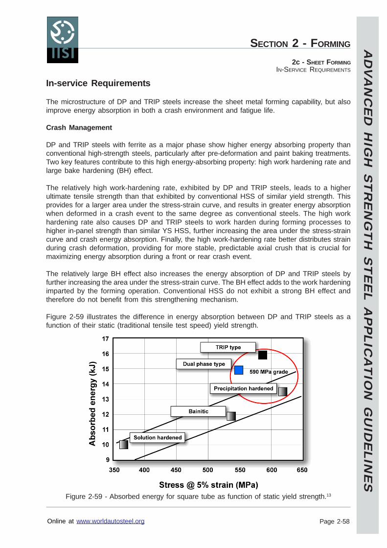
AD
VA
NC
ED
HIG
H S
TR
EN
GT
H S
TE
EL A
PP
LICA
TIO
N G
UID
ELIN
ES
Online at www.worldautosteel.org
SECTION 2 - FORMING
Page 2-58
2c - SHEET FORMINGIN-SERVICE REQUIREMENTS
In-service Requirements
The microstructure of DP and TRIP steels increase the sheet metal forming capability, but alsoimprove energy absorption in both a crash environment and fatigue life.
Crash Management
DP and TRIP steels with ferrite as a major phase show higher energy absorbing property thanconventional high-strength steels, particularly after pre-deformation and paint baking treatments.Two key features contribute to this high energy-absorbing property: high work hardening rate andlarge bake hardening (BH) effect.
The relatively high work-hardening rate, exhibited by DP and TRIP steels, leads to a higherultimate tensile strength than that exhibited by conventional HSS of similar yield strength. Thisprovides for a larger area under the stress-strain curve, and results in greater energy absorptionwhen deformed in a crash event to the same degree as conventional steels. The high workhardening rate also causes DP and TRIP steels to work harden during forming processes tohigher in-panel strength than similar YS HSS, further increasing the area under the stress-straincurve and crash energy absorption. Finally, the high work-hardening rate better distributes strainduring crash deformation, providing for more stable, predictable axial crush that is crucial formaximizing energy absorption during a front or rear crash event.
The relatively large BH effect also increases the energy absorption of DP and TRIP steels byfurther increasing the area under the stress-strain curve. The BH effect adds to the work hardeningimparted by the forming operation. Conventional HSS do not exhibit a strong BH effect andtherefore do not benefit from this strengthening mechanism.
Figure 2-59 illustrates the difference in energy absorption between DP and TRIP steels as afunction of their static (traditional tensile test speed) yield strength.
Figure 2-59 - Absorbed energy for square tube as function of static yield strength.13
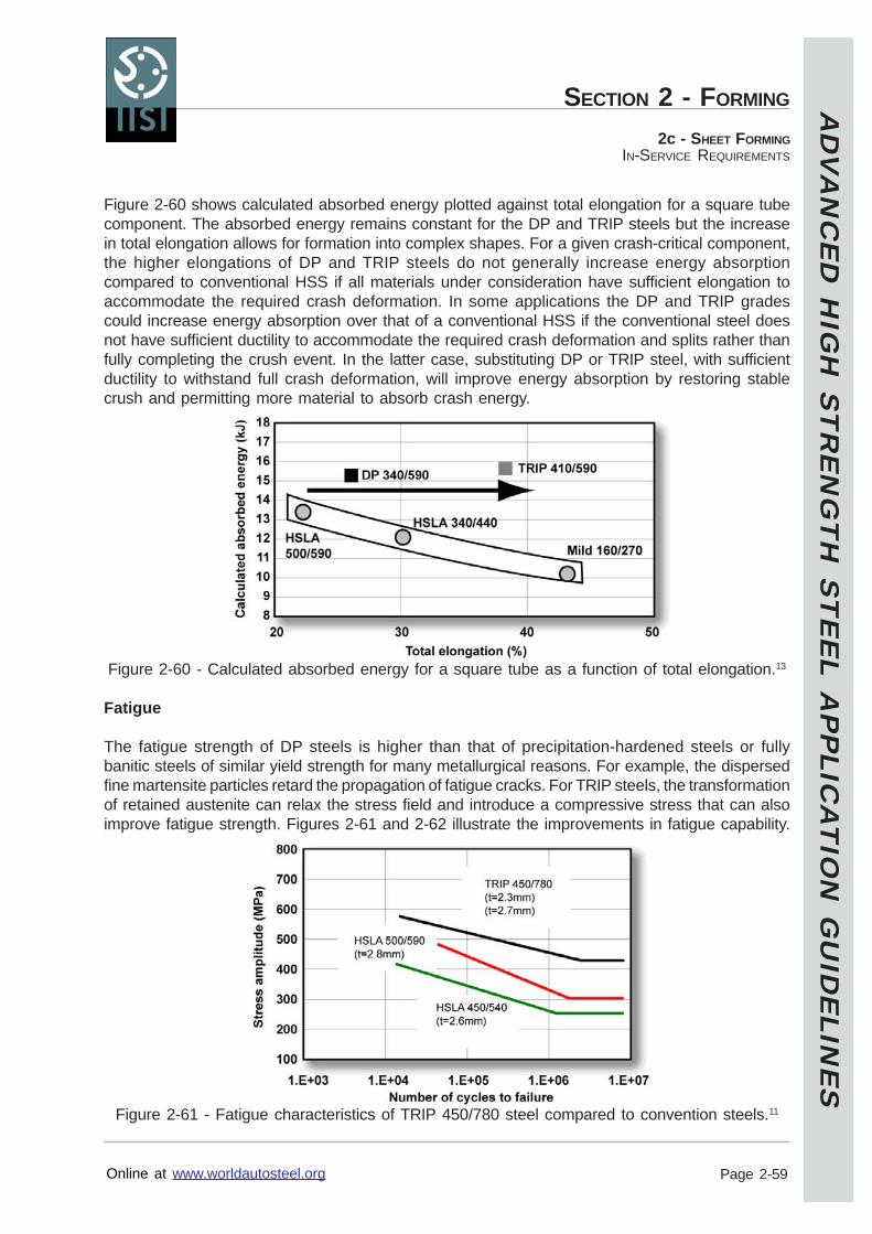
AD
VA
NC
ED
HIG
H S
TR
EN
GT
H S
TE
EL A
PP
LICA
TIO
N G
UID
ELIN
ES
Online at www.worldautosteel.org
SECTION 2 - FORMING
Page 2-59
2c - SHEET FORMINGIN-SERVICE REQUIREMENTS
Figure 2-60 shows calculated absorbed energy plotted against total elongation for a square tubecomponent. The absorbed energy remains constant for the DP and TRIP steels but the increasein total elongation allows for formation into complex shapes. For a given crash-critical component,the higher elongations of DP and TRIP steels do not generally increase energy absorptioncompared to conventional HSS if all materials under consideration have sufficient elongation toaccommodate the required crash deformation. In some applications the DP and TRIP gradescould increase energy absorption over that of a conventional HSS if the conventional steel doesnot have sufficient ductility to accommodate the required crash deformation and splits rather thanfully completing the crush event. In the latter case, substituting DP or TRIP steel, with sufficientductility to withstand full crash deformation, will improve energy absorption by restoring stablecrush and permitting more material to absorb crash energy.
Figure 2-60 - Calculated absorbed energy for a square tube as a function of total elongation.13
Fatigue
The fatigue strength of DP steels is higher than that of precipitation-hardened steels or fullybanitic steels of similar yield strength for many metallurgical reasons. For example, the dispersedfine martensite particles retard the propagation of fatigue cracks. For TRIP steels, the transformationof retained austenite can relax the stress field and introduce a compressive stress that can alsoimprove fatigue strength. Figures 2-61 and 2-62 illustrate the improvements in fatigue capability.
Figure 2-61 - Fatigue characteristics of TRIP 450/780 steel compared to convention steels.11
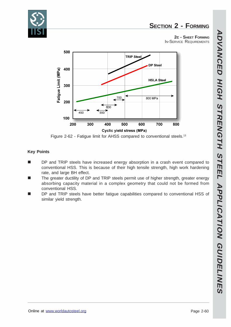
AD
VA
NC
ED
HIG
H S
TR
EN
GT
H S
TE
EL A
PP
LICA
TIO
N G
UID
ELIN
ES
Online at www.worldautosteel.org
SECTION 2 - FORMING
Page 2-60
2c - SHEET FORMINGIN-SERVICE REQUIREMENTS
Figure 2-62 - Fatigue limit for AHSS compared to conventional steels.13
Key Points
DP and TRIP steels have increased energy absorption in a crash event compared toconventional HSS. This is because of their high tensile strength, high work hardeningrate, and large BH effect.The greater ductility of DP and TRIP steels permit use of higher strength, greater energyabsorbing capacity material in a complex geometry that could not be formed fromconventional HSS.DP and TRIP steels have better fatigue capabilities compared to conventional HSS ofsimilar yield strength.
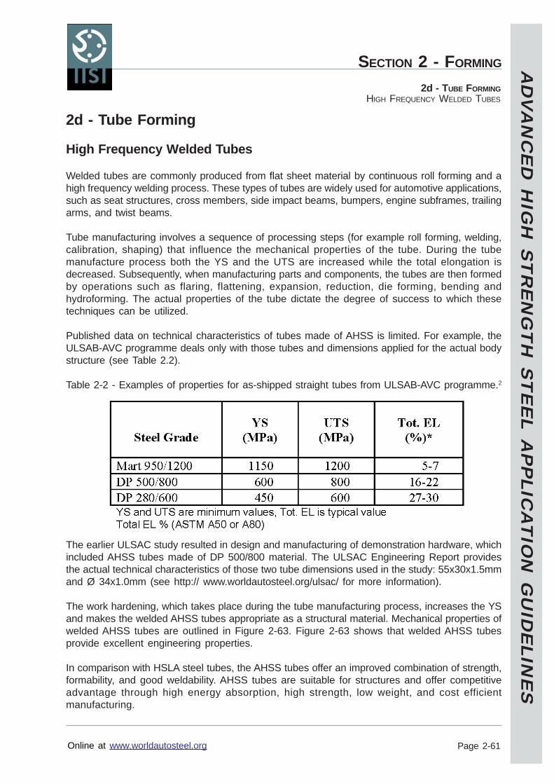
AD
VA
NC
ED
HIG
H S
TR
EN
GT
H S
TE
EL A
PP
LICA
TIO
N G
UID
ELIN
ES
Online at www.worldautosteel.org
SECTION 2 - FORMING
Page 2-61
2d - TUBE FORMINGHIGH FREQUENCY WELDED TUBES
2d - Tube Forming
High Frequency Welded Tubes
Welded tubes are commonly produced from flat sheet material by continuous roll forming and ahigh frequency welding process. These types of tubes are widely used for automotive applications,such as seat structures, cross members, side impact beams, bumpers, engine subframes, trailingarms, and twist beams.
Tube manufacturing involves a sequence of processing steps (for example roll forming, welding,calibration, shaping) that influence the mechanical properties of the tube. During the tubemanufacture process both the YS and the UTS are increased while the total elongation isdecreased. Subsequently, when manufacturing parts and components, the tubes are then formedby operations such as flaring, flattening, expansion, reduction, die forming, bending andhydroforming. The actual properties of the tube dictate the degree of success to which thesetechniques can be utilized.
Published data on technical characteristics of tubes made of AHSS is limited. For example, theULSAB-AVC programme deals only with those tubes and dimensions applied for the actual bodystructure (see Table 2.2).
Table 2-2 - Examples of properties for as-shipped straight tubes from ULSAB-AVC programme.2
The earlier ULSAC study resulted in design and manufacturing of demonstration hardware, whichincluded AHSS tubes made of DP 500/800 material. The ULSAC Engineering Report providesthe actual technical characteristics of those two tube dimensions used in the study: 55x30x1.5mmand Ø 34x1.0mm (see http:// www.worldautosteel.org/ulsac/ for more information).
The work hardening, which takes place during the tube manufacturing process, increases the YSand makes the welded AHSS tubes appropriate as a structural material. Mechanical properties ofwelded AHSS tubes are outlined in Figure 2-63. Figure 2-63 shows that welded AHSS tubesprovide excellent engineering properties.
In comparison with HSLA steel tubes, the AHSS tubes offer an improved combination of strength,formability, and good weldability. AHSS tubes are suitable for structures and offer competitiveadvantage through high energy absorption, high strength, low weight, and cost efficientmanufacturing.
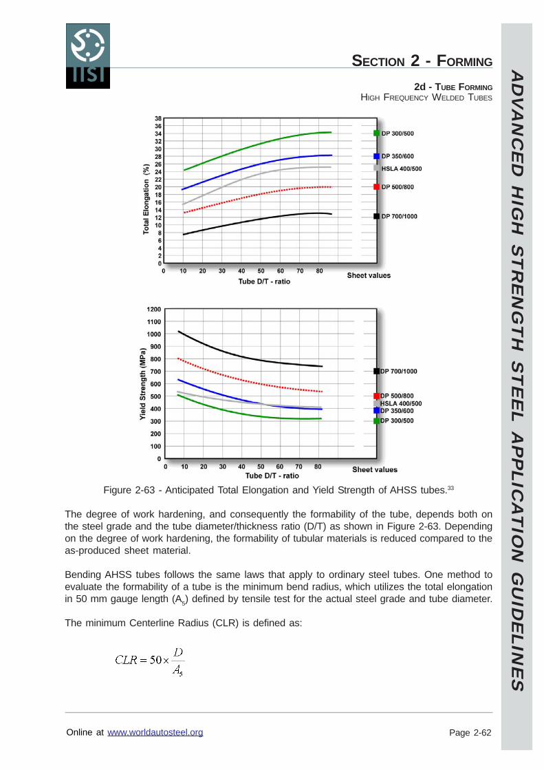
AD
VA
NC
ED
HIG
H S
TR
EN
GT
H S
TE
EL A
PP
LICA
TIO
N G
UID
ELIN
ES
Online at www.worldautosteel.org
SECTION 2 - FORMING
Page 2-62
2d - TUBE FORMINGHIGH FREQUENCY WELDED TUBES
Figure 2-63 - Anticipated Total Elongation and Yield Strength of AHSS tubes.33
The degree of work hardening, and consequently the formability of the tube, depends both onthe steel grade and the tube diameter/thickness ratio (D/T) as shown in Figure 2-63. Dependingon the degree of work hardening, the formability of tubular materials is reduced compared to theas-produced sheet material.
Bending AHSS tubes follows the same laws that apply to ordinary steel tubes. One method toevaluate the formability of a tube is the minimum bend radius, which utilizes the total elongationin 50 mm gauge length (A5) defined by tensile test for the actual steel grade and tube diameter.
The minimum Centerline Radius (CLR) is defined as:
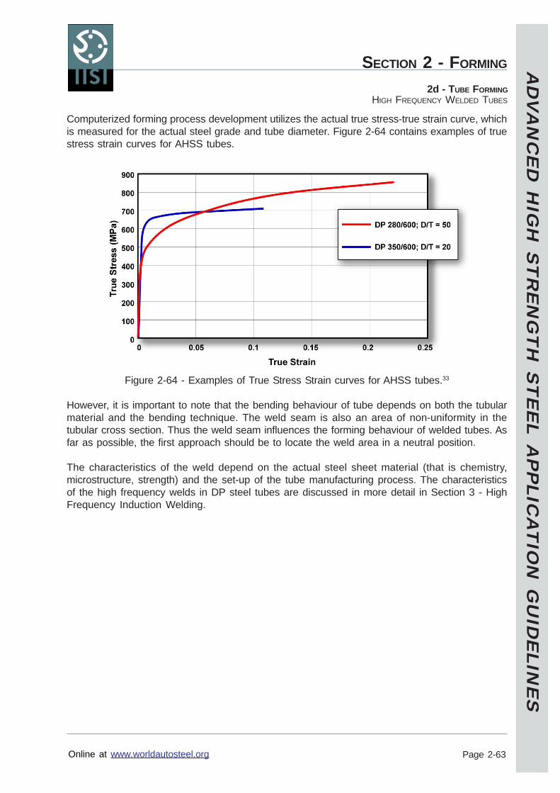
AD
VA
NC
ED
HIG
H S
TR
EN
GT
H S
TE
EL A
PP
LICA
TIO
N G
UID
ELIN
ES
Online at www.worldautosteel.org
SECTION 2 - FORMING
Page 2-63
2d - TUBE FORMINGHIGH FREQUENCY WELDED TUBES
Computerized forming process development utilizes the actual true stress-true strain curve, whichis measured for the actual steel grade and tube diameter. Figure 2-64 contains examples of truestress strain curves for AHSS tubes.
Figure 2-64 - Examples of True Stress Strain curves for AHSS tubes.33
However, it is important to note that the bending behaviour of tube depends on both the tubularmaterial and the bending technique. The weld seam is also an area of non-uniformity in thetubular cross section. Thus the weld seam influences the forming behaviour of welded tubes. Asfar as possible, the first approach should be to locate the weld area in a neutral position.
The characteristics of the weld depend on the actual steel sheet material (that is chemistry,microstructure, strength) and the set-up of the tube manufacturing process. The characteristicsof the high frequency welds in DP steel tubes are discussed in more detail in Section 3 - HighFrequency Induction Welding.
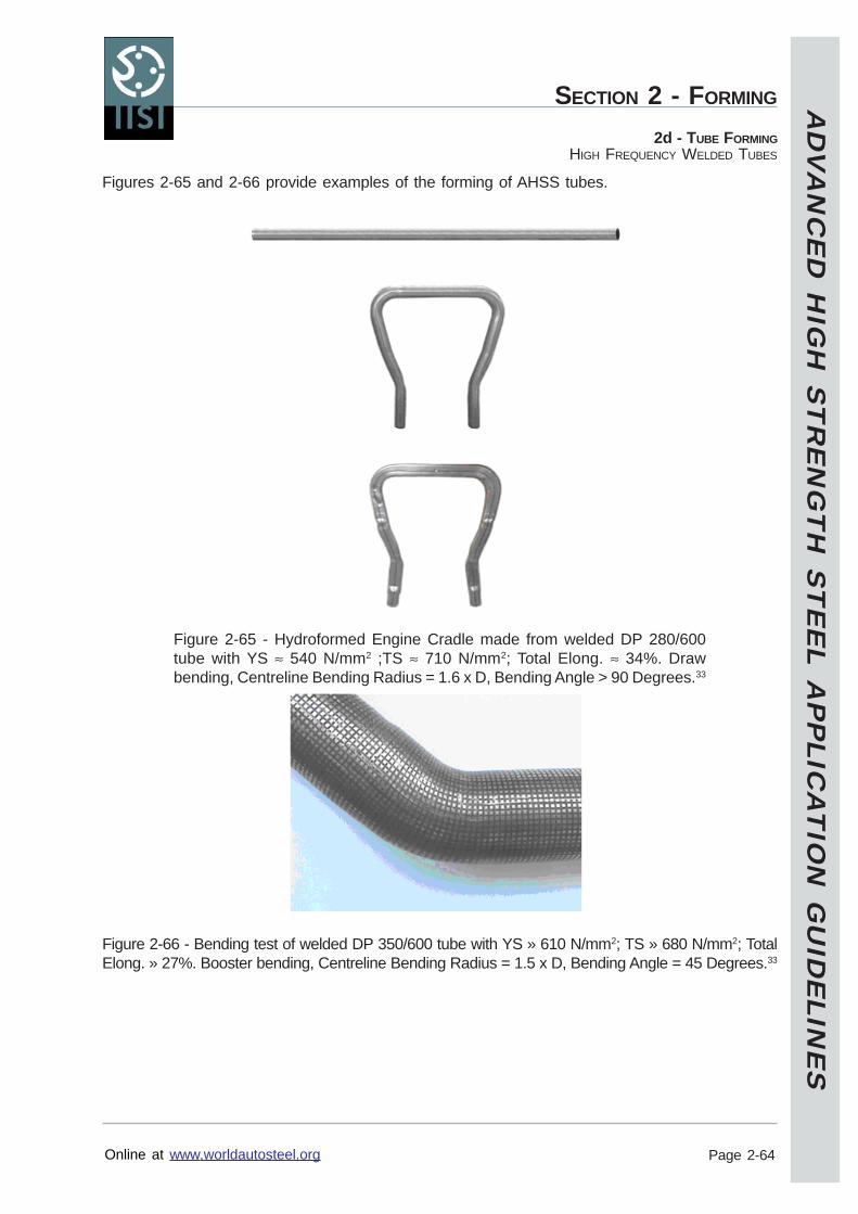
AD
VA
NC
ED
HIG
H S
TR
EN
GT
H S
TE
EL A
PP
LICA
TIO
N G
UID
ELIN
ES
Online at www.worldautosteel.org
SECTION 2 - FORMING
Page 2-64
2d - TUBE FORMINGHIGH FREQUENCY WELDED TUBES
Figures 2-65 and 2-66 provide examples of the forming of AHSS tubes.
Figure 2-65 - Hydroformed Engine Cradle made from welded DP 280/600tube with YS ≈ 540 N/mm2 ;TS ≈ 710 N/mm2; Total Elong. ≈ 34%. Drawbending, Centreline Bending Radius = 1.6 x D, Bending Angle > 90 Degrees.33
Figure 2-66 - Bending test of welded DP 350/600 tube with YS » 610 N/mm2; TS » 680 N/mm2; TotalElong. » 27%. Booster bending, Centreline Bending Radius = 1.5 x D, Bending Angle = 45 Degrees.33
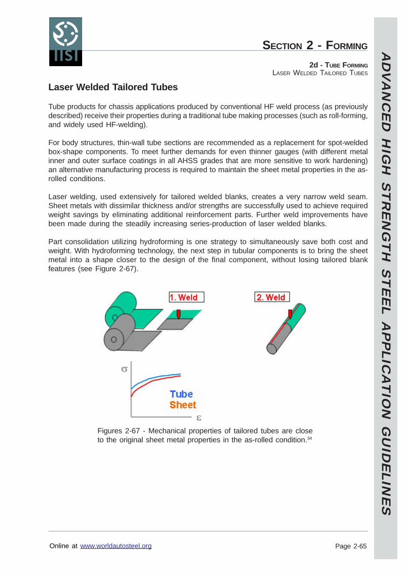
AD
VA
NC
ED
HIG
H S
TR
EN
GT
H S
TE
EL A
PP
LICA
TIO
N G
UID
ELIN
ES
Online at www.worldautosteel.org
SECTION 2 - FORMING
Page 2-65
2d - TUBE FORMINGLASER WELDED TAILORED TUBES
Laser Welded Tailored Tubes
Tube products for chassis applications produced by conventional HF weld process (as previouslydescribed) receive their properties during a traditional tube making processes (such as roll-forming,and widely used HF-welding).
For body structures, thin-wall tube sections are recommended as a replacement for spot-weldedbox-shape components. To meet further demands for even thinner gauges (with different metalinner and outer surface coatings in all AHSS grades that are more sensitive to work hardening)an alternative manufacturing process is required to maintain the sheet metal properties in the as-rolled conditions.
Laser welding, used extensively for tailored welded blanks, creates a very narrow weld seam.Sheet metals with dissimilar thickness and/or strengths are successfully used to achieve requiredweight savings by eliminating additional reinforcement parts. Further weld improvements havebeen made during the steadily increasing series-production of laser welded blanks.
Part consolidation utilizing hydroforming is one strategy to simultaneously save both cost andweight. With hydroforming technology, the next step in tubular components is to bring the sheetmetal into a shape closer to the design of the final component, without losing tailored blankfeatures (see Figure 2-67).
Figures 2-67 - Mechanical properties of tailored tubes are closeto the original sheet metal properties in the as-rolled condition.34
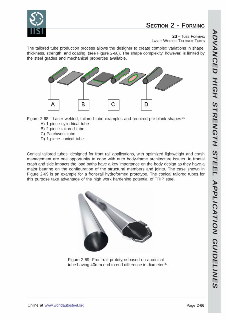
AD
VA
NC
ED
HIG
H S
TR
EN
GT
H S
TE
EL A
PP
LICA
TIO
N G
UID
ELIN
ES
Online at www.worldautosteel.org
SECTION 2 - FORMING
Page 2-66
2d - TUBE FORMINGLASER WELDED TAILORED TUBES
The tailored tube production process allows the designer to create complex variations in shape,thickness, strength, and coating. (see Figure 2-68). The shape complexity, however, is limited bythe steel grades and mechanical properties available.
Figure 2-68 - Laser welded, tailored tube examples and required pre-blank shapes:35
A) 1-piece cylindrical tubeB) 2-piece tailored tubeC) Patchwork tubeD) 1-piece conical tube
Conical tailored tubes, designed for front rail applications, with optimized lightweight and crashmanagement are one opportunity to cope with auto body-frame architecture issues. In frontalcrash and side impacts the load paths have a key importance on the body design as they have amajor bearing on the configuration of the structural members and joints. The case shown inFigure 2-69 is an example for a front-rail hydroformed prototype. The conical tailored tubes forthis purpose take advantage of the high work hardening potential of TRIP steel.
Figure 2-69- Front-rail prototype based on a conicaltube having 40mm end to end difference in diameter.36
AD
VA
NC
ED
HIG
H S
TR
EN
GT
H S
TE
EL A
PP
LICA
TIO
N G
UID
ELIN
ES
Online at www.worldautosteel.org
SECTION 2 - FORMING
Page 2-67
2d - TUBE FORMINGLASER WELDED TAILORED TUBES
Key Points
Due to the cold working generated during tube forming, the formability of the tube isreduced compared to the as-received sheet.The work hardening during tube forming increases the YS and TS, thereby allowing thetube to be a structural member.Laser welded tubes create a very narrow weld seam.The weld seam should be located at the neutral axis of the tube, whenever possible.
AD
VA
NC
ED
HIG
H S
TR
EN
GT
H S
TE
EL A
PP
LICA
TIO
N G
UID
ELIN
ES
Online at www.worldautosteel.org
Revised: 18 Mar 2005
Page 3-1
Section 3 - Joining
3a - General Comments
The application of AHSS provides its largest benefit in the potential for safety and mass reduction.With the application of thinner AHSS, material savings and/or improved crash energy managementcan be achieved. AHSS are produced uncoated, EG, HDG, and GA. Unless differences arehighlighted, joining coated and uncoated AHSS is the same as conventional steels.
The Applications Guidelines document utilizes a steel designation system to minimize regionalconfusion about the mechanical properties when comparing AHSS to conventional high strengthsteels. The format is Steel Type YS/TS in MPa. Therefore, HSLA 350/450 would have minimumyield strength of 350 MPa and minimum tensile strength of 450 MPa. The designation also highlightsdifferent yield strengths for steel grades with equal tensile strengths, thereby allowing someassessment of the stress-strain curves and amount of work hardening.
AHSS can be satisfactorily welded for automotive applications. AHSS differ from mild steels bychemical composition and microstructure. In AHSS, higher strengths are achieved by modifyingthe steel microstructure. The as-received microstructure will be changed while welding AHSS.The higher the heat input, the greater the effect on the microstructure. At fast cooling, it is normalto see martensite and/or bainite microstructures in the weld metal and in the HAZ.
When joining AHSS, production process control is more important for successful assembly.Manufacturers with highly developed joining control methodology will experience no major changein their operations. Others may require additional checks and maintenance. In certain instancesminor modifications to equipment or processing methodologies may be required for successfuljoining of AHSS.
The coating methods for AHSS are similar to that for mild steels. Welding of either AHSS or mildsteels will generate fumes. The amount and nature of fumes will depend on the coating thickness,coating composition, joining method, and fillers used to join these materials. The fumes maycontain some pollutants. The chemical composition of fumes and the relevant exhaust equipmentmust meet appropriate regulatory standards. To minimize pollutant formation, unnecessarily thickcoatings and high heat inputs should be avoided. Additional exhausters should be installed.While welding AHSS, with or without metallic or organic coatings and oiled or not oiled, gasesand weld fumes will arise that are similar to mild steels. The allowed fumes or gases have tocomply with respective national rules and regulations.
The intent of these guidelines is to provide information regarding aspects of the joining processes– recognizing that more data is needed in some areas to be complete.
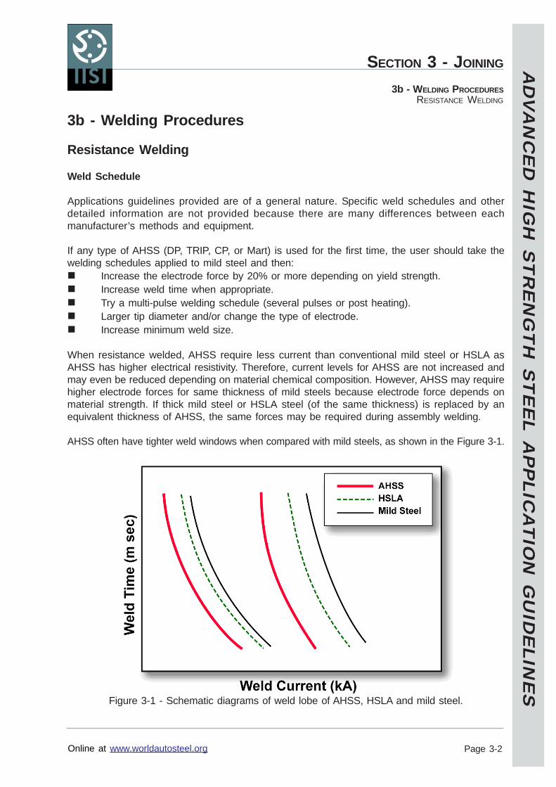
AD
VA
NC
ED
HIG
H S
TR
EN
GT
H S
TE
EL A
PP
LICA
TIO
N G
UID
ELIN
ES
Online at www.worldautosteel.org
SECTION 3 - JOINING
Page 3-2
3b - WELDING PROCEDURESRESISTANCE WELDING
3b - Welding Procedures
Resistance Welding
Weld Schedule
Applications guidelines provided are of a general nature. Specific weld schedules and otherdetailed information are not provided because there are many differences between eachmanufacturer’s methods and equipment.
If any type of AHSS (DP, TRIP, CP, or Mart) is used for the first time, the user should take thewelding schedules applied to mild steel and then:
Increase the electrode force by 20% or more depending on yield strength.Increase weld time when appropriate.Try a multi-pulse welding schedule (several pulses or post heating).Larger tip diameter and/or change the type of electrode.Increase minimum weld size.
When resistance welded, AHSS require less current than conventional mild steel or HSLA asAHSS has higher electrical resistivity. Therefore, current levels for AHSS are not increased andmay even be reduced depending on material chemical composition. However, AHSS may requirehigher electrode forces for same thickness of mild steels because electrode force depends onmaterial strength. If thick mild steel or HSLA steel (of the same thickness) is replaced by anequivalent thickness of AHSS, the same forces may be required during assembly welding.
AHSS often have tighter weld windows when compared with mild steels, as shown in the Figure 3-1.
Figure 3-1 - Schematic diagrams of weld lobe of AHSS, HSLA and mild steel.
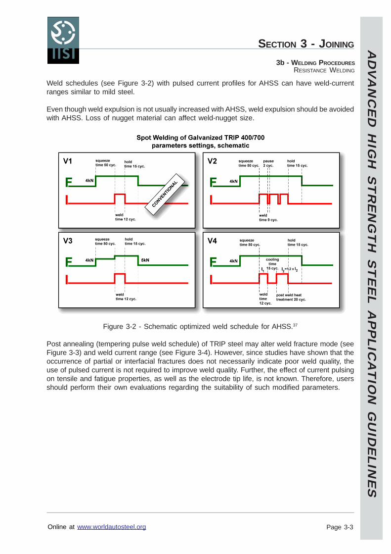
AD
VA
NC
ED
HIG
H S
TR
EN
GT
H S
TE
EL A
PP
LICA
TIO
N G
UID
ELIN
ES
Online at www.worldautosteel.org
SECTION 3 - JOINING
Page 3-3
3b - WELDING PROCEDURESRESISTANCE WELDING
Weld schedules (see Figure 3-2) with pulsed current profiles for AHSS can have weld-currentranges similar to mild steel.
Even though weld expulsion is not usually increased with AHSS, weld expulsion should be avoidedwith AHSS. Loss of nugget material can affect weld-nugget size.
Figure 3-2 - Schematic optimized weld schedule for AHSS.37
Post annealing (tempering pulse weld schedule) of TRIP steel may alter weld fracture mode (seeFigure 3-3) and weld current range (see Figure 3-4). However, since studies have shown that theoccurrence of partial or interfacial fractures does not necessarily indicate poor weld quality, theuse of pulsed current is not required to improve weld quality. Further, the effect of current pulsingon tensile and fatigue properties, as well as the electrode tip life, is not known. Therefore, usersshould perform their own evaluations regarding the suitability of such modified parameters.
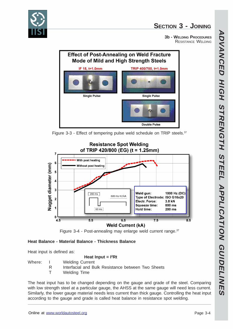
AD
VA
NC
ED
HIG
H S
TR
EN
GT
H S
TE
EL A
PP
LICA
TIO
N G
UID
ELIN
ES
Online at www.worldautosteel.org
SECTION 3 - JOINING
Page 3-4
3b - WELDING PROCEDURESRESISTANCE WELDING
Figure 3-3 - Effect of tempering pulse weld schedule on TRIP steels.37
Figure 3-4 - Post-annealing may enlarge weld current range.37
Heat Balance - Material Balance - Thickness Balance
Heat input is defined as:Heat Input = I2Rt
Where: I Welding CurrentR Interfacial and Bulk Resistance between Two SheetsT Welding Time
The heat input has to be changed depending on the gauge and grade of the steel. Comparingwith low strength steel at a particular gauge, the AHSS at the same gauge will need less current.Similarly, the lower gauge material needs less current than thick gauge. Controlling the heat inputaccording to the gauge and grade is called heat balance in resistance spot welding.
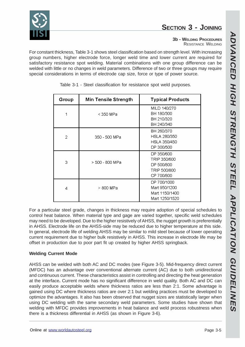
AD
VA
NC
ED
HIG
H S
TR
EN
GT
H S
TE
EL A
PP
LICA
TIO
N G
UID
ELIN
ES
Online at www.worldautosteel.org
SECTION 3 - JOINING
Page 3-5
3b - WELDING PROCEDURESRESISTANCE WELDING
For constant thickness, Table 3-1 shows steel classification based on strength level. With increasinggroup numbers, higher electrode force, longer weld time and lower current are required forsatisfactory resistance spot welding. Material combinations with one group difference can bewelded with little or no changes in weld parameters. Difference of two or three groups may requirespecial considerations in terms of electrode cap size, force or type of power source.
Table 3-1 - Steel classification for resistance spot weld purposes.
For a particular steel grade, changes in thickness may require adoption of special schedules tocontrol heat balance. When material type and gage are varied together, specific weld schedulesmay need to be developed. Due to the higher resistively of AHSS, the nugget growth is preferentiallyin AHSS. Electrode life on the AHSS-side may be reduced due to higher temperature at this side.In general, electrode life of welding AHSS may be similar to mild steel because of lower operatingcurrent requirement due to higher bulk resistively in AHSS. This increase in electrode life may beoffset in production due to poor part fit up created by higher AHSS springback.
Welding Current Mode
AHSS can be welded with both AC and DC modes (see Figure 3-5). Mid-frequency direct current(MFDC) has an advantage over conventional alternate current (AC) due to both unidirectionaland continuous current. These characteristics assist in controlling and directing the heat generationat the interface. Current mode has no significant difference in weld quality. Both AC and DC caneasily produce acceptable welds where thickness ratios are less than 2:1. Some advantage isgained using DC where thickness ratios are over 2:1 but welding practices must be developed tooptimize the advantages. It also has been observed that nugget sizes are statistically larger whenusing DC welding with the same secondary weld parameters. Some studies have shown thatwelding with MFDC provides improvements in heat balance and weld process robustness whenthere is a thickness differential in AHSS (as shown in Figure 3-6).
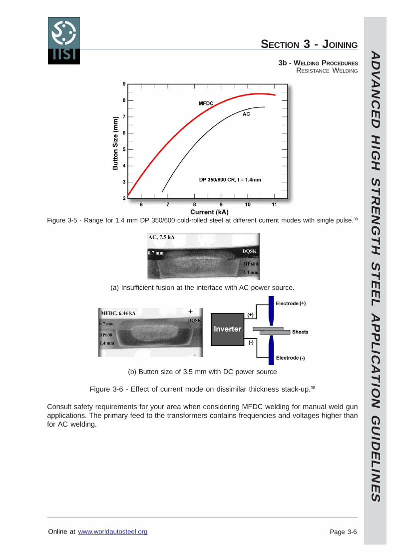
AD
VA
NC
ED
HIG
H S
TR
EN
GT
H S
TE
EL A
PP
LICA
TIO
N G
UID
ELIN
ES
Online at www.worldautosteel.org
SECTION 3 - JOINING
Page 3-6
3b - WELDING PROCEDURESRESISTANCE WELDING
Figure 3-5 - Range for 1.4 mm DP 350/600 cold-rolled steel at different current modes with single pulse.38
(a) Insufficient fusion at the interface with AC power source.
(b) Button size of 3.5 mm with DC power source
Figure 3-6 - Effect of current mode on dissimilar thickness stack-up.38
Consult safety requirements for your area when considering MFDC welding for manual weld gunapplications. The primary feed to the transformers contains frequencies and voltages higher thanfor AC welding.
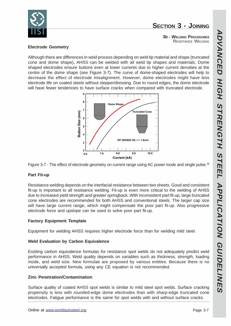
AD
VA
NC
ED
HIG
H S
TR
EN
GT
H S
TE
EL A
PP
LICA
TIO
N G
UID
ELIN
ES
Online at www.worldautosteel.org
SECTION 3 - JOINING
Page 3-7
3b - WELDING PROCEDURESRESISTANCE WELDING
Electrode Geometry
Although there are differences in weld process depending on weld tip material and shape (truncatedcone and dome shape), AHSS can be welded with all weld tip shapes and materials. Domeshaped electrodes ensure buttons even at lower currents due to higher current densities at thecentre of the dome shape (see Figure 3-7). The curve of dome-shaped electrodes will help todecrease the effect of electrode misalignment. However, dome electrodes might have lesselectrode life on coated steels without stepper/dressing. Due to round edges, the dome electrodewill have fewer tendencies to have surface cracks when compared with truncated electrode.
Figure 3-7 - The effect of electrode geometry on current range using AC power mode and single pulse.38
Part Fit-up
Resistance welding depends on the interfacial resistance between two sheets. Good and consistentfit-up is important to all resistance welding. Fit-up is even more critical to the welding of AHSSdue to increased yield strength and greater springback. With inconsistent part fit-up, large truncatedcone electrodes are recommended for both AHSS and conventional steels. The larger cap sizewill have large current range, which might compensate the poor part fit-up. Also progressiveelectrode force and upslope can be used to solve poor part fit-up.
Factory Equipment Template
Equipment for welding AHSS requires higher electrode force than for welding mild steel.
Weld Evaluation by Carbon Equivalence
Existing carbon equivalence formulas for resistance spot welds do not adequately predict weldperformance in AHSS. Weld quality depends on variables such as thickness, strength, loadingmode, and weld size. New formulae are proposed by various entities. Because there is nouniversally accepted formula, using any CE equation is not recommended.
Zinc Penetration/Contamination
Surface quality of coated AHSS spot welds is similar to mild steel spot welds. Surface crackingpropensity is less with rounded-edge dome electrodes than with sharp-edge truncated coneelectrodes. Fatigue performance is the same for spot welds with and without surface cracks.
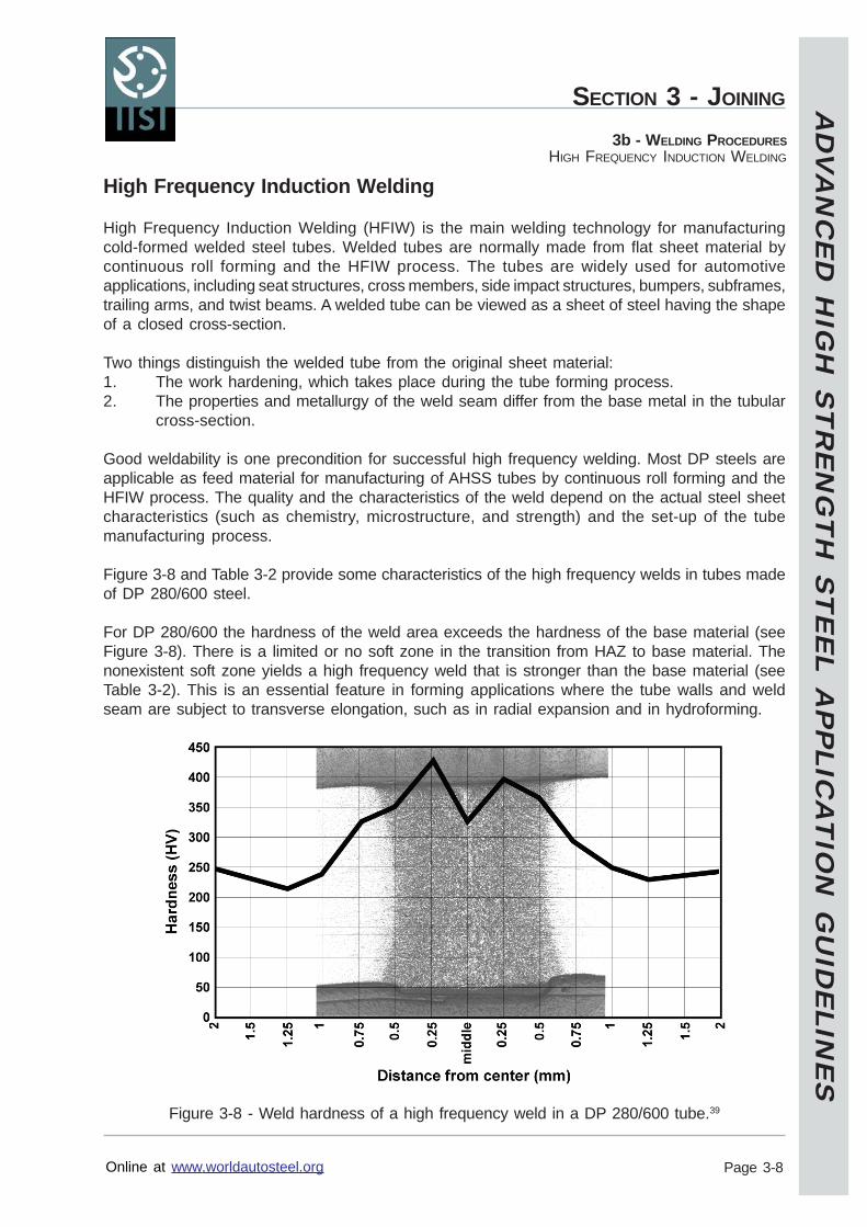
AD
VA
NC
ED
HIG
H S
TR
EN
GT
H S
TE
EL A
PP
LICA
TIO
N G
UID
ELIN
ES
Online at www.worldautosteel.org
SECTION 3 - JOINING
Page 3-8
3b - WELDING PROCEDURESHIGH FREQUENCY INDUCTION WELDING
High Frequency Induction Welding
High Frequency Induction Welding (HFIW) is the main welding technology for manufacturingcold-formed welded steel tubes. Welded tubes are normally made from flat sheet material bycontinuous roll forming and the HFIW process. The tubes are widely used for automotiveapplications, including seat structures, cross members, side impact structures, bumpers, subframes,trailing arms, and twist beams. A welded tube can be viewed as a sheet of steel having the shapeof a closed cross-section.
Two things distinguish the welded tube from the original sheet material:1. The work hardening, which takes place during the tube forming process.2. The properties and metallurgy of the weld seam differ from the base metal in the tubular
cross-section.
Good weldability is one precondition for successful high frequency welding. Most DP steels areapplicable as feed material for manufacturing of AHSS tubes by continuous roll forming and theHFIW process. The quality and the characteristics of the weld depend on the actual steel sheetcharacteristics (such as chemistry, microstructure, and strength) and the set-up of the tubemanufacturing process.
Figure 3-8 and Table 3-2 provide some characteristics of the high frequency welds in tubes madeof DP 280/600 steel.
For DP 280/600 the hardness of the weld area exceeds the hardness of the base material (seeFigure 3-8). There is a limited or no soft zone in the transition from HAZ to base material. Thenonexistent soft zone yields a high frequency weld that is stronger than the base material (seeTable 3-2). This is an essential feature in forming applications where the tube walls and weldseam are subject to transverse elongation, such as in radial expansion and in hydroforming.
Figure 3-8 - Weld hardness of a high frequency weld in a DP 280/600 tube.39
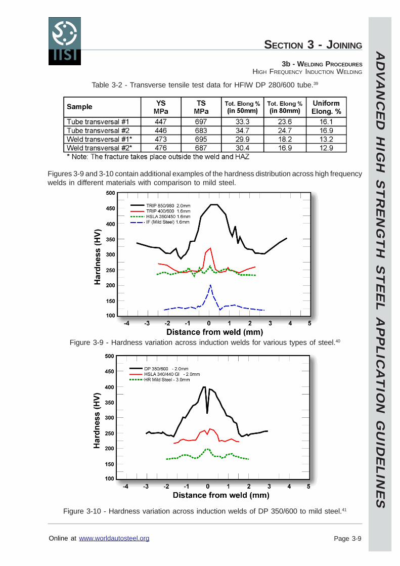
AD
VA
NC
ED
HIG
H S
TR
EN
GT
H S
TE
EL A
PP
LICA
TIO
N G
UID
ELIN
ES
Online at www.worldautosteel.org
SECTION 3 - JOINING
Page 3-9
3b - WELDING PROCEDURESHIGH FREQUENCY INDUCTION WELDING
Table 3-2 - Transverse tensile test data for HFIW DP 280/600 tube.39
Figures 3-9 and 3-10 contain additional examples of the hardness distribution across high frequencywelds in different materials with comparison to mild steel.
Figure 3-9 - Hardness variation across induction welds for various types of steel.40
Figure 3-10 - Hardness variation across induction welds of DP 350/600 to mild steel.41
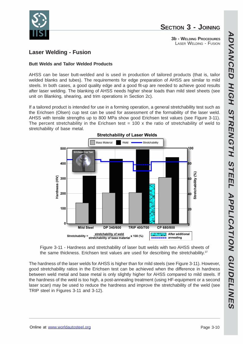
AD
VA
NC
ED
HIG
H S
TR
EN
GT
H S
TE
EL A
PP
LICA
TIO
N G
UID
ELIN
ES
Online at www.worldautosteel.org
SECTION 3 - JOINING
Page 3-10
3b - WELDING PROCEDURESLASER WELDING - FUSION
Laser Welding - Fusion
Butt Welds and Tailor Welded Products
AHSS can be laser butt-welded and is used in production of tailored products (that is, tailorwelded blanks and tubes). The requirements for edge preparation of AHSS are similar to mildsteels. In both cases, a good quality edge and a good fit-up are needed to achieve good resultsafter laser welding. The blanking of AHSS needs higher shear loads than mild steel sheets (seeunit on Blanking, shearing, and trim operations in Section 2c).
If a tailored product is intended for use in a forming operation, a general stretchability test such asthe Erichsen (Olsen) cup test can be used for assessment of the formability of the laser weld.AHSS with tensile strengths up to 800 MPa show good Erichsen test values (see Figure 3-11).The percent stretchability in the Erichsen test = 100 x the ratio of stretchability of weld tostretchability of base metal.
Figure 3-11 - Hardness and stretchability of laser butt welds with two AHSS sheets ofthe same thickness. Erichsen test values are used for describing the stretchability.37
The hardness of the laser welds for AHSS is higher than for mild steels (see Figure 3-11). However,good stretchability ratios in the Erichsen test can be achieved when the difference in hardnessbetween weld metal and base metal is only slightly higher for AHSS compared to mild steels. Ifthe hardness of the weld is too high, a post-annealing treatment (using HF-equipment or a secondlaser scan) may be used to reduce the hardness and improve the stretchability of the weld (seeTRIP steel in Figures 3-11 and 3-12).
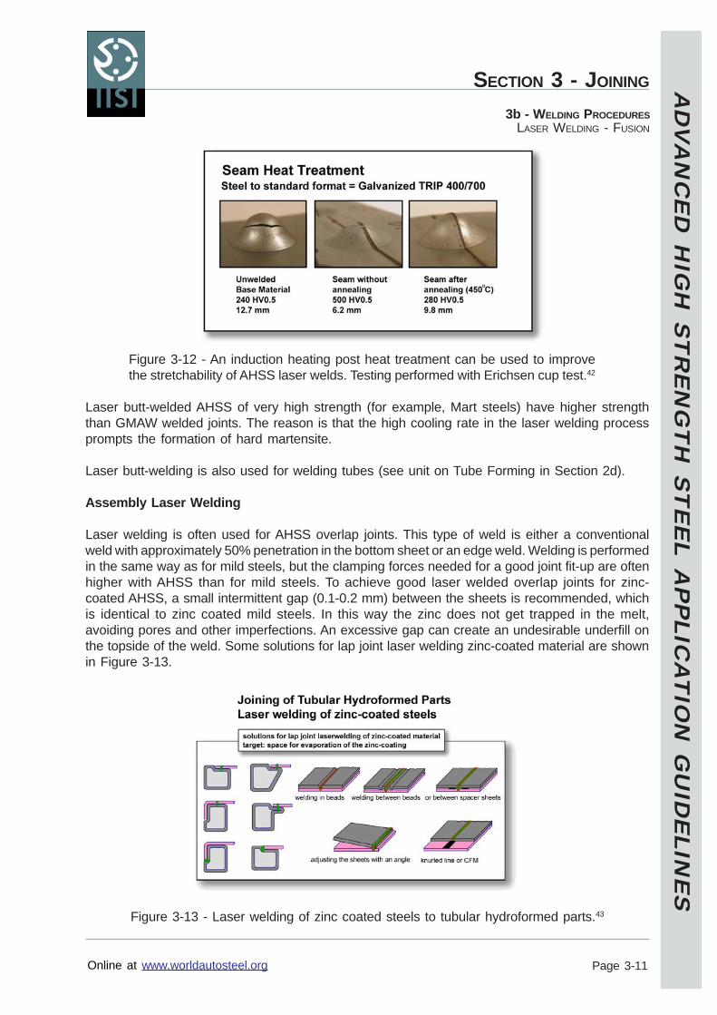
AD
VA
NC
ED
HIG
H S
TR
EN
GT
H S
TE
EL A
PP
LICA
TIO
N G
UID
ELIN
ES
Online at www.worldautosteel.org
SECTION 3 - JOINING
Page 3-11
3b - WELDING PROCEDURESLASER WELDING - FUSION
Figure 3-12 - An induction heating post heat treatment can be used to improvethe stretchability of AHSS laser welds. Testing performed with Erichsen cup test.42
Laser butt-welded AHSS of very high strength (for example, Mart steels) have higher strengththan GMAW welded joints. The reason is that the high cooling rate in the laser welding processprompts the formation of hard martensite.
Laser butt-welding is also used for welding tubes (see unit on Tube Forming in Section 2d).
Assembly Laser Welding
Laser welding is often used for AHSS overlap joints. This type of weld is either a conventionalweld with approximately 50% penetration in the bottom sheet or an edge weld. Welding is performedin the same way as for mild steels, but the clamping forces needed for a good joint fit-up are oftenhigher with AHSS than for mild steels. To achieve good laser welded overlap joints for zinc-coated AHSS, a small intermittent gap (0.1-0.2 mm) between the sheets is recommended, whichis identical to zinc coated mild steels. In this way the zinc does not get trapped in the melt,avoiding pores and other imperfections. An excessive gap can create an undesirable underfill onthe topside of the weld. Some solutions for lap joint laser welding zinc-coated material are shownin Figure 3-13.
Figure 3-13 - Laser welding of zinc coated steels to tubular hydroformed parts.43
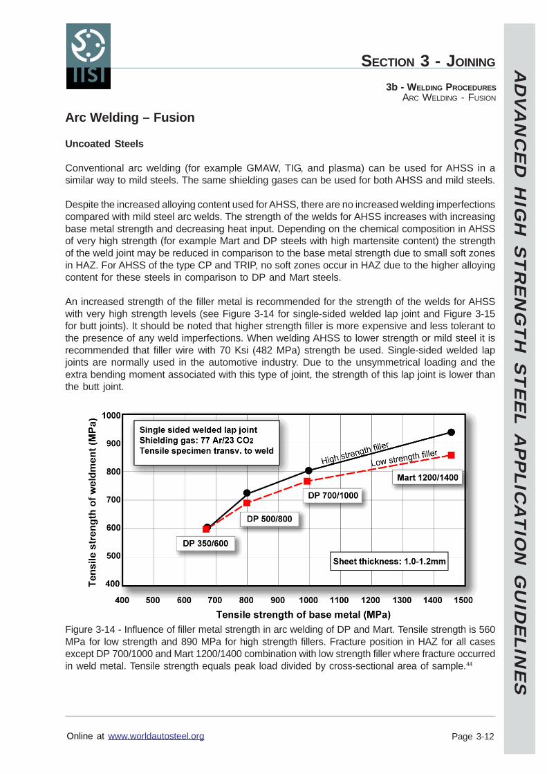
AD
VA
NC
ED
HIG
H S
TR
EN
GT
H S
TE
EL A
PP
LICA
TIO
N G
UID
ELIN
ES
Online at www.worldautosteel.org
SECTION 3 - JOINING
Page 3-12
3b - WELDING PROCEDURESARC WELDING - FUSION
Arc Welding – Fusion
Uncoated Steels
Conventional arc welding (for example GMAW, TIG, and plasma) can be used for AHSS in asimilar way to mild steels. The same shielding gases can be used for both AHSS and mild steels.
Despite the increased alloying content used for AHSS, there are no increased welding imperfectionscompared with mild steel arc welds. The strength of the welds for AHSS increases with increasingbase metal strength and decreasing heat input. Depending on the chemical composition in AHSSof very high strength (for example Mart and DP steels with high martensite content) the strengthof the weld joint may be reduced in comparison to the base metal strength due to small soft zonesin HAZ. For AHSS of the type CP and TRIP, no soft zones occur in HAZ due to the higher alloyingcontent for these steels in comparison to DP and Mart steels.
An increased strength of the filler metal is recommended for the strength of the welds for AHSSwith very high strength levels (see Figure 3-14 for single-sided welded lap joint and Figure 3-15for butt joints). It should be noted that higher strength filler is more expensive and less tolerant tothe presence of any weld imperfections. When welding AHSS to lower strength or mild steel it isrecommended that filler wire with 70 Ksi (482 MPa) strength be used. Single-sided welded lapjoints are normally used in the automotive industry. Due to the unsymmetrical loading and theextra bending moment associated with this type of joint, the strength of this lap joint is lower thanthe butt joint.
Figure 3-14 - Influence of filler metal strength in arc welding of DP and Mart. Tensile strength is 560MPa for low strength and 890 MPa for high strength fillers. Fracture position in HAZ for all casesexcept DP 700/1000 and Mart 1200/1400 combination with low strength filler where fracture occurredin weld metal. Tensile strength equals peak load divided by cross-sectional area of sample.44
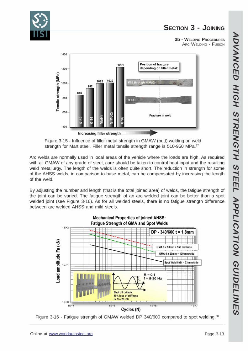
AD
VA
NC
ED
HIG
H S
TR
EN
GT
H S
TE
EL A
PP
LICA
TIO
N G
UID
ELIN
ES
Online at www.worldautosteel.org
SECTION 3 - JOINING
Page 3-13
3b - WELDING PROCEDURESARC WELDING - FUSION
Figure 3-15 - Influence of filler metal strength in GMAW (butt) welding on weldstrength for Mart steel. Filler metal tensile strength range is 510-950 MPa.37
Arc welds are normally used in local areas of the vehicle where the loads are high. As requiredwith all GMAW of any grade of steel, care should be taken to control heat input and the resultingweld metallurgy. The length of the welds is often quite short. The reduction in strength for someof the AHSS welds, in comparison to base metal, can be compensated by increasing the lengthof the weld.
By adjusting the number and length (that is the total joined area) of welds, the fatigue strength ofthe joint can be varied. The fatigue strength of an arc welded joint can be better than a spotwelded joint (see Figure 3-16). As for all welded steels, there is no fatigue strength differencebetween arc welded AHSS and mild steels.
Figure 3-16 - Fatigue strength of GMAW welded DP 340/600 compared to spot welding.38
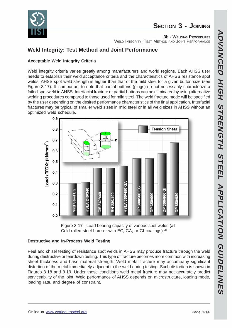
AD
VA
NC
ED
HIG
H S
TR
EN
GT
H S
TE
EL A
PP
LICA
TIO
N G
UID
ELIN
ES
Online at www.worldautosteel.org
SECTION 3 - JOINING
Page 3-14
3b - WELDING PROCEDURESWELD INTEGRITY: TEST METHOD AND JOINT PERFORMANCE
Weld Integrity: Test Method and Joint Performance
Acceptable Weld Integrity Criteria
Weld integrity criteria varies greatly among manufacturers and world regions. Each AHSS userneeds to establish their weld acceptance criteria and the characteristics of AHSS resistance spotwelds. AHSS spot weld strength is higher than that of the mild steel for a given button size (seeFigure 3-17). It is important to note that partial buttons (plugs) do not necessarily characterize afailed spot weld in AHSS. Interfacial fracture or partial buttons can be eliminated by using alternativewelding procedures compared to those used for mild steel. The weld fracture mode will be specifiedby the user depending on the desired performance characteristics of the final application. Interfacialfractures may be typical of smaller weld sizes in mild steel or in all weld sizes in AHSS without anoptimized weld schedule.
Figure 3-17 - Load bearing capacity of various spot welds (allCold-rolled steel bare or with EG, GA, or GI coatings).38
Destructive and In-Process Weld Testing
Peel and chisel testing of resistance spot welds in AHSS may produce fracture through the weldduring destructive or teardown testing. This type of fracture becomes more common with increasingsheet thickness and base material strength. Weld metal fracture may accompany significantdistortion of the metal immediately adjacent to the weld during testing. Such distortion is shown inFigures 3-18 and 3-19. Under these conditions weld metal fracture may not accurately predictserviceability of the joint. Weld performance of AHSS depends on microstructure, loading mode,loading rate, and degree of constraint.
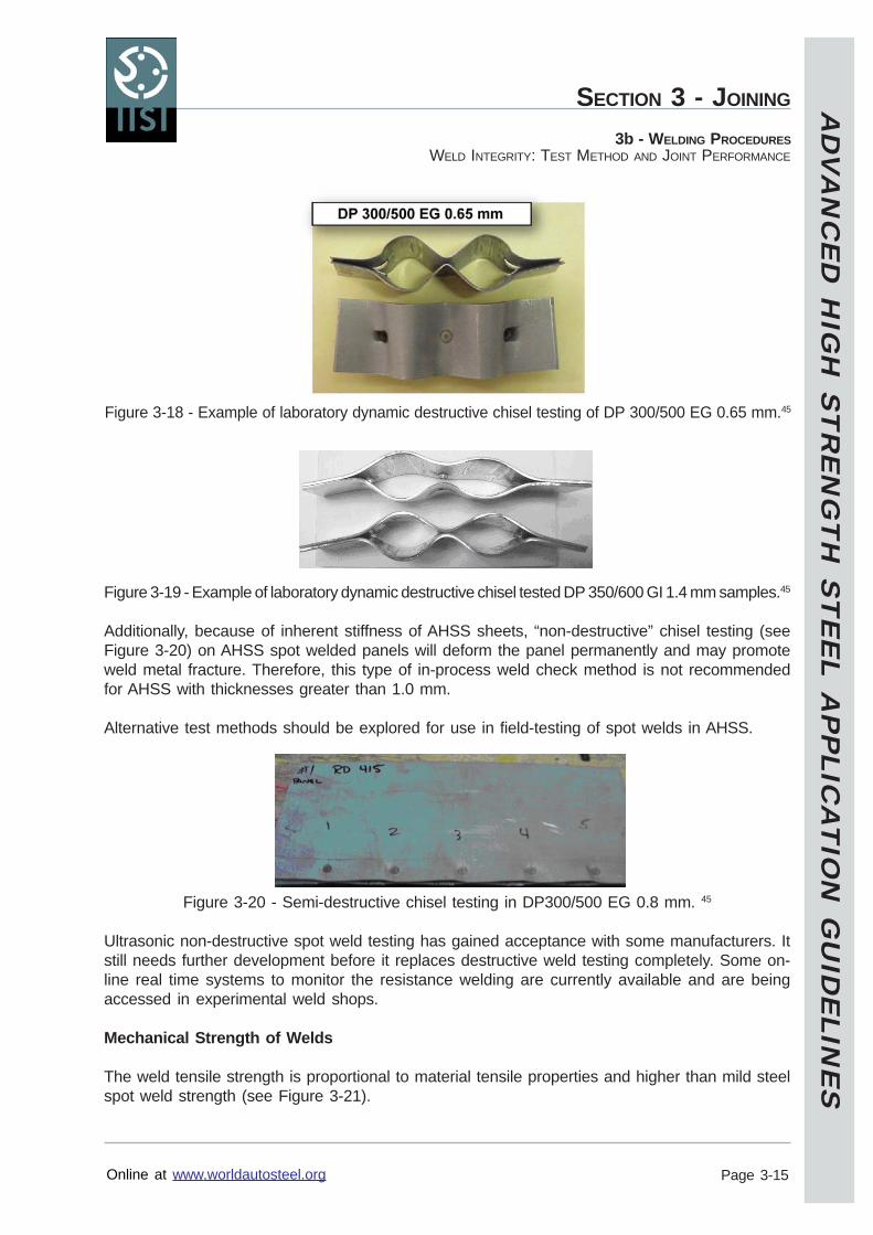
AD
VA
NC
ED
HIG
H S
TR
EN
GT
H S
TE
EL A
PP
LICA
TIO
N G
UID
ELIN
ES
Online at www.worldautosteel.org
SECTION 3 - JOINING
Page 3-15
3b - WELDING PROCEDURESWELD INTEGRITY: TEST METHOD AND JOINT PERFORMANCE
Figure 3-19 - Example of laboratory dynamic destructive chisel tested DP 350/600 GI 1.4 mm samples.45
Additionally, because of inherent stiffness of AHSS sheets, “non-destructive” chisel testing (seeFigure 3-20) on AHSS spot welded panels will deform the panel permanently and may promoteweld metal fracture. Therefore, this type of in-process weld check method is not recommendedfor AHSS with thicknesses greater than 1.0 mm.
Alternative test methods should be explored for use in field-testing of spot welds in AHSS.
Figure 3-20 - Semi-destructive chisel testing in DP300/500 EG 0.8 mm. 45
Ultrasonic non-destructive spot weld testing has gained acceptance with some manufacturers. Itstill needs further development before it replaces destructive weld testing completely. Some on-line real time systems to monitor the resistance welding are currently available and are beingaccessed in experimental weld shops.
Mechanical Strength of Welds
The weld tensile strength is proportional to material tensile properties and higher than mild steelspot weld strength (see Figure 3-21).
Figure 3-18 - Example of laboratory dynamic destructive chisel testing of DP 300/500 EG 0.65 mm.45
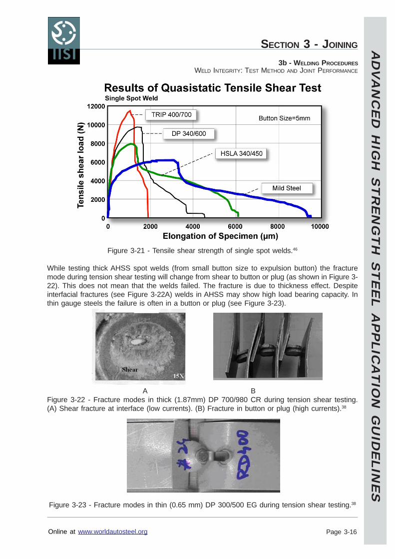
AD
VA
NC
ED
HIG
H S
TR
EN
GT
H S
TE
EL A
PP
LICA
TIO
N G
UID
ELIN
ES
Online at www.worldautosteel.org
SECTION 3 - JOINING
Page 3-16
3b - WELDING PROCEDURESWELD INTEGRITY: TEST METHOD AND JOINT PERFORMANCE
Figure 3-21 - Tensile shear strength of single spot welds.46
While testing thick AHSS spot welds (from small button size to expulsion button) the fracturemode during tension shear testing will change from shear to button or plug (as shown in Figure 3-22). This does not mean that the welds failed. The fracture is due to thickness effect. Despiteinterfacial fractures (see Figure 3-22A) welds in AHSS may show high load bearing capacity. Inthin gauge steels the failure is often in a button or plug (see Figure 3-23).
A BFigure 3-22 - Fracture modes in thick (1.87mm) DP 700/980 CR during tension shear testing.(A) Shear fracture at interface (low currents). (B) Fracture in button or plug (high currents).38
Figure 3-23 - Fracture modes in thin (0.65 mm) DP 300/500 EG during tension shear testing.38
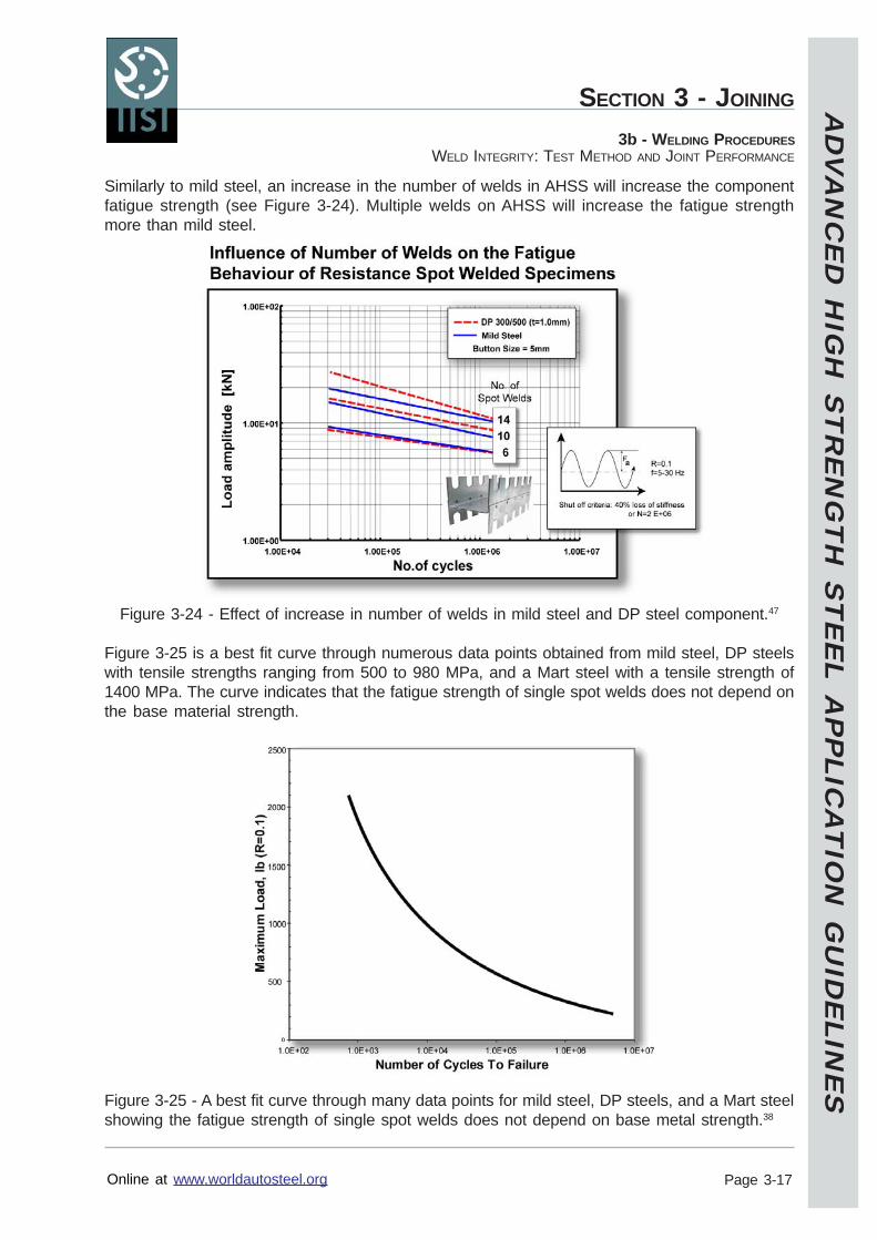
AD
VA
NC
ED
HIG
H S
TR
EN
GT
H S
TE
EL A
PP
LICA
TIO
N G
UID
ELIN
ES
Online at www.worldautosteel.org
SECTION 3 - JOINING
Page 3-17
3b - WELDING PROCEDURESWELD INTEGRITY: TEST METHOD AND JOINT PERFORMANCE
Similarly to mild steel, an increase in the number of welds in AHSS will increase the componentfatigue strength (see Figure 3-24). Multiple welds on AHSS will increase the fatigue strengthmore than mild steel.
Figure 3-24 - Effect of increase in number of welds in mild steel and DP steel component.47
Figure 3-25 is a best fit curve through numerous data points obtained from mild steel, DP steelswith tensile strengths ranging from 500 to 980 MPa, and a Mart steel with a tensile strength of1400 MPa. The curve indicates that the fatigue strength of single spot welds does not depend onthe base material strength.
Figure 3-25 - A best fit curve through many data points for mild steel, DP steels, and a Mart steelshowing the fatigue strength of single spot welds does not depend on base metal strength.38
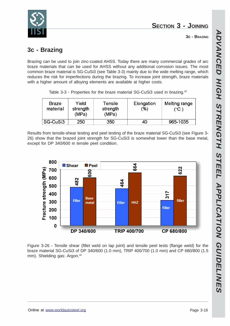
AD
VA
NC
ED
HIG
H S
TR
EN
GT
H S
TE
EL A
PP
LICA
TIO
N G
UID
ELIN
ES
Online at www.worldautosteel.org
SECTION 3 - JOINING
Page 3-18
3c - BRAZING
3c - Brazing
Brazing can be used to join zinc-coated AHSS. Today there are many commercial grades of arcbraze materials that can be used for AHSS without any additional corrosion issues. The mostcommon braze material is SG-CuSi3 (see Table 3-3) mainly due to the wide melting range, whichreduces the risk for imperfections during the brazing. To increase joint strength, braze materialswith a higher amount of alloying elements are available at higher costs.
Table 3-3 - Properties for the braze material SG-CuSi3 used in brazing.42
Results from tensile-shear testing and peel testing of the braze material SG-CuSi3 (see Figure 3-26) show that the brazed joint strength for SG-CuSi3 is somewhat lower than the base metal,except for DP 340/600 in tensile peel condition.
Figure 3-26 - Tensile shear (fillet weld on lap joint) and tensile peel tests (flange weld) for thebraze material SG-CuSi3 of DP 340/600 (1.0 mm), TRIP 400/700 (1.0 mm) and CP 680/800 (1.5mm). Shielding gas: Argon.42
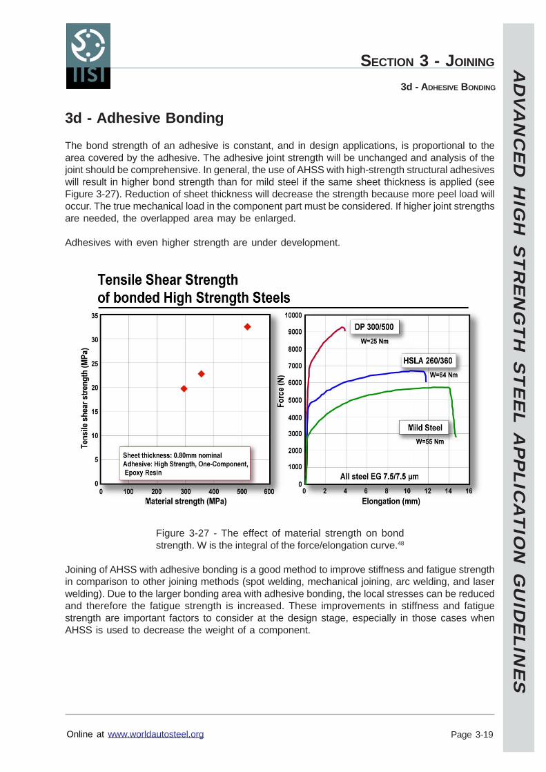
AD
VA
NC
ED
HIG
H S
TR
EN
GT
H S
TE
EL A
PP
LICA
TIO
N G
UID
ELIN
ES
Online at www.worldautosteel.org
SECTION 3 - JOINING
Page 3-19
3d - ADHESIVE BONDING
3d - Adhesive Bonding
The bond strength of an adhesive is constant, and in design applications, is proportional to thearea covered by the adhesive. The adhesive joint strength will be unchanged and analysis of thejoint should be comprehensive. In general, the use of AHSS with high-strength structural adhesiveswill result in higher bond strength than for mild steel if the same sheet thickness is applied (seeFigure 3-27). Reduction of sheet thickness will decrease the strength because more peel load willoccur. The true mechanical load in the component part must be considered. If higher joint strengthsare needed, the overlapped area may be enlarged.
Adhesives with even higher strength are under development.
Figure 3-27 - The effect of material strength on bondstrength. W is the integral of the force/elongation curve.48
Joining of AHSS with adhesive bonding is a good method to improve stiffness and fatigue strengthin comparison to other joining methods (spot welding, mechanical joining, arc welding, and laserwelding). Due to the larger bonding area with adhesive bonding, the local stresses can be reducedand therefore the fatigue strength is increased. These improvements in stiffness and fatiguestrength are important factors to consider at the design stage, especially in those cases whenAHSS is used to decrease the weight of a component.
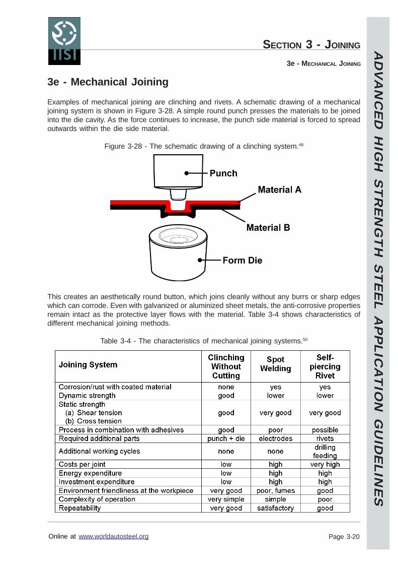
AD
VA
NC
ED
HIG
H S
TR
EN
GT
H S
TE
EL A
PP
LICA
TIO
N G
UID
ELIN
ES
Online at www.worldautosteel.org
SECTION 3 - JOINING
Page 3-20
3e - MECHANICAL JOINING
3e - Mechanical Joining
Examples of mechanical joining are clinching and rivets. A schematic drawing of a mechanicaljoining system is shown in Figure 3-28. A simple round punch presses the materials to be joinedinto the die cavity. As the force continues to increase, the punch side material is forced to spreadoutwards within the die side material.
Figure 3-28 - The schematic drawing of a clinching system.49
This creates an aesthetically round button, which joins cleanly without any burrs or sharp edgeswhich can corrode. Even with galvanized or aluminized sheet metals, the anti-corrosive propertiesremain intact as the protective layer flows with the material. Table 3-4 shows characteristics ofdifferent mechanical joining methods.
Table 3-4 - The characteristics of mechanical joining systems.50
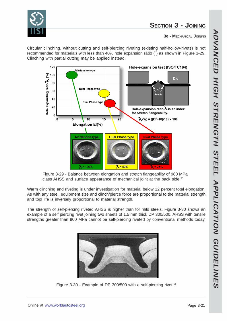
AD
VA
NC
ED
HIG
H S
TR
EN
GT
H S
TE
EL A
PP
LICA
TIO
N G
UID
ELIN
ES
Online at www.worldautosteel.org
SECTION 3 - JOINING
Page 3-21
3e - MECHANICAL JOINING
Circular clinching, without cutting and self-piercing riveting (existing half-hollow-rivets) is notrecommended for materials with less than 40% hole expansion ratio (˜) as shown in Figure 3-29.Clinching with partial cutting may be applied instead.
Figure 3-29 - Balance between elongation and stretch flangeability of 980 MPaclass AHSS and surface appearance of mechanical joint at the back side.50
Warm clinching and riveting is under investigation for material below 12 percent total elongation.As with any steel, equipment size and clinch/pierce force are proportional to the material strengthand tool life is inversely proportional to material strength.
The strength of self-piercing riveted AHSS is higher than for mild steels. Figure 3-30 shows anexample of a self piercing rivet joining two sheets of 1.5 mm thick DP 300/500. AHSS with tensilestrengths greater than 900 MPa cannot be self-piercing riveted by conventional methods today.
Figure 3-30 - Example of DP 300/500 with a self-piercing rivet.51
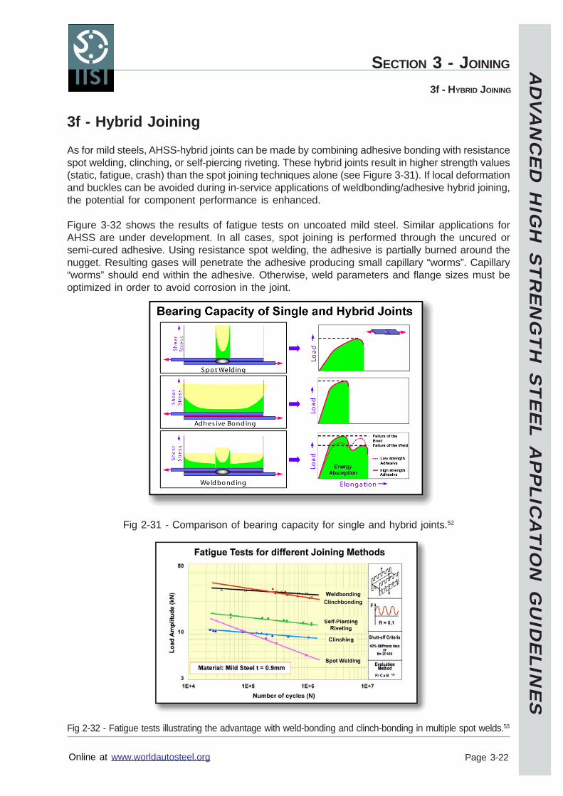
AD
VA
NC
ED
HIG
H S
TR
EN
GT
H S
TE
EL A
PP
LICA
TIO
N G
UID
ELIN
ES
Online at www.worldautosteel.org
SECTION 3 - JOINING
Page 3-22
3f - HYBRID JOINING
3f - Hybrid Joining
As for mild steels, AHSS-hybrid joints can be made by combining adhesive bonding with resistancespot welding, clinching, or self-piercing riveting. These hybrid joints result in higher strength values(static, fatigue, crash) than the spot joining techniques alone (see Figure 3-31). If local deformationand buckles can be avoided during in-service applications of weldbonding/adhesive hybrid joining,the potential for component performance is enhanced.
Figure 3-32 shows the results of fatigue tests on uncoated mild steel. Similar applications forAHSS are under development. In all cases, spot joining is performed through the uncured orsemi-cured adhesive. Using resistance spot welding, the adhesive is partially burned around thenugget. Resulting gases will penetrate the adhesive producing small capillary “worms”. Capillary“worms” should end within the adhesive. Otherwise, weld parameters and flange sizes must beoptimized in order to avoid corrosion in the joint.
Fig 2-31 - Comparison of bearing capacity for single and hybrid joints.52
Fig 2-32 - Fatigue tests illustrating the advantage with weld-bonding and clinch-bonding in multiple spot welds.53
AD
VA
NC
ED
HIG
H S
TR
EN
GT
H S
TE
EL A
PP
LICA
TIO
N G
UID
ELIN
ES
Online at www.worldautosteel.org
SECTION 3 - JOINING
Page 3-23
3g - MATERIAL ISSUES FOR WELD REPAIR
3g - Material Issues For Weld Repair
The American Iron and Steel Institute (AISI), in cooperation with North American OEM’s, hasundertaken studies to understand the influences of “in field” repair practices on some AHSS.54
Studies have been completed for DP, Mart, and TRIP steels. In particular, the effects of MIG(Metal Inert Gas) welding and a practice called “flame straightening” were examined.
Test results indicate that GMAW welding is acceptable as a repair method for AHSS such as DP,Mart, and TRIP. Mechanical properties are within the expected range for each material in closeproximity to the repair weld and are therefore acceptable.
However, flame straightening consists of heating a portion of the body or frame structure that hasbeen deformed in a collision to 650 ºC (dull cherry red) for 90 seconds and then pulling thedeformed portion of the structure to its original position. This heating cycle then could be appliedtwice. Test results indicate that “flame straightening” should NOT be used to repair AHSS such asDP, Mart, and TRIP. The heating cycle causes degradation to the mechanical properties of as-formed (work hardened) body part.
Therefore, repair of AHSS parts using GMAW in the field may be acceptable. In any event, theOEM’s specific recommendations for the material and vehicle should be followed.
AD
VA
NC
ED
HIG
H S
TR
EN
GT
H S
TE
EL A
PP
LICA
TIO
N G
UID
ELIN
ES
Online at www.worldautosteel.org
Revised: 18 Mar 2005
Page 4-1
Section 4 – GlossaryAdvanced High-Strength Steel (AHSS): A series of high-strength steel types with novel metallurgyand processing compared to conventional high-strength steels. This results in differentcombinations of higher strength levels, improved formability, and/or increased crash energyabsorption.
Aging: A change in material property or properties with time.
Angular change: Springback resulting from a change in radius at the punch with a resultingchange in flange position usually described as a springback angle.
Anisotropy: Variations in one or more physical or mechanical properties with direction in thesheet metal. Related terms are normal anisotropy, planar anisotropy, and plastic strain ratio.
Austenite: Normally not found in steel at room temperature, austenite is a homogeneous phaseconsisting of a solid solution of carbon in the gamma form of iron. It is formed when steel isheated to temperature above the upper critical point. Rapid quenching of the austenite will producemartensite.
Bake Hardening steel (BH): Any high-strength steel that increases in strength as a result of acombination of straining and aging at a temperature and time typical of the automotive paint curecycle.
Bake hardening: Generally means a change in mechanical properties created during a typicalautomotive paint bake cycle.
Bend: A simple bending process to reduce the sidewall curl because the sidewall does not undergoone or more sequences of bend and unbend.
Binder: Alternatively called a blank holder or holddown. The part of a forming die that holds theblank by pressure against a mating surface of the die to control metal flow and prevent wrinkling.
Burr: The rough cut edge of metal.
Carbon equivalent: Various equations using percent concentrations of carbon, manganese,chromium, molybdenum, and sometimes other elements to predict the weldability of a givensteel.
Carbon Manganese steel (CM): High-strength steels primarily strengthened by solid solutionstrengthening.
Clinching: Mechanical joining systems where the punch forces the two sheets of metal to spreadoutward in the die and interlock.
Complex Phase steel (CP): A steel with very fine microstructure of ferrite and higher volumefractions of hard phases that are further strengthened by fine precipitates.
AD
VA
NC
ED
HIG
H S
TR
EN
GT
H S
TE
EL A
PP
LICA
TIO
N G
UID
ELIN
ES
Online at www.worldautosteel.org
SECTION 4 - GLOSSARY
Page 4-2
Computerized forming simulation: More accurately defined as computerized forming processdevelopment, where the forming of a stamping is accomplished in the computer without constructionof hard tooling. Used to determine if the initial product design can be formed, evaluate variousproduct and process design options, and obtain additional production requirements such asmaximum required press load.
Cup drawing: A press forming operation in which a cup shaped (often cylindrical) part is producedfrom a sheet metal blank (often circular in shape).
Curl (sidewall): Springback resulting from metal moving over a radius. Curl is characterized byan average radius of curvature.
Die clearance: The space, on each side, between the punch and die.
Draw bead: A ridge constructed around a portion of a die cavity to partially restrain metal flow. Agroove in the mating blankholder allows die closing. Sometimes called a die bead.
Draw: A conventional forming operation with continuous blankholder force.
Dual Phase steel (DP): A steel consisting of a ferrite matrix containing a hard second phase inthe form of islands.
Elastic deformation: Deformation which will return to its original shape and dimensions uponremoval of the load or stress.
Elastic limit: The maximum stress to which a material may be subjected and yet return to itsoriginal shape and dimensions upon removal of the stress.
Elongation: The amount of permanent extension in a tensile test or any segment of a sheetmetal stamping.
Embossing: Displacing a section of metal a minor amount without noticeable reduction in sheetmetal thickness or metal flow from surrounding sheet metal.
Engineering strain: The unit elongation given by the change in length divided by the originallength. Sometimes called the nominal strain.
Engineering stress: The unit force obtained when the applied load is divided by the originalcross-sectional area. Sometime called the nominal stress.
Erichsen test: A test in which a piece of sheet metal, restrained except at the centre, is deformedby a spherical punch until fracture occurs. The height of the cup at fracture is a measure ofductility. Similar to the Olsen test.
Filler metal: Available in the form of rods, spooled wire, or consumable inserts to improve thequality of the welded part.
Form: A forming process that allows the flange to be created in the last stage of forming and thesheet metal undergoes only a slight amount of bend-unbend deformation.
AD
VA
NC
ED
HIG
H S
TR
EN
GT
H S
TE
EL A
PP
LICA
TIO
N G
UID
ELIN
ES
Online at www.worldautosteel.org
SECTION 4 - GLOSSARY
Page 4-3
Form-draw: A forming process in which the blankholder force is applied from the middle to laststage of forming.
Forming Limit Curve (FLC): An empirical curve showing the levels of different combinations ofbiaxial strain beyond which failure (local necking) may occur in sheet metal forming. The strainsare given in terms of major and minor strains measured from deformed circles previously imprintedas circles into the undeformed sheet metal.
Gas Metal Arc Welding (GMAW): An arc welding process that uses a continuously fed consumableelectrode and a shielding gas. Common GMAW processes are MIG (metal inert gas) welding andMAG (metal active gas) welding.
Heat Affected Zone (HAZ): A zone paralleling the weld zone where a change in properties hastaken place as a result of the heat generated by the welding process.
Heat balance: The phenomenon in resistance spot welding of balancing the heat input duringthe weld based on the gauge and grade of steel.
High-Strength, Low Alloy steel (HSLA): Steels that generally contain microalloying elementssuch as titanium, vanadium, or niobium, which increase strength by grain size control, precipitationhardening, and solid solution hardening.
High-Strength steel (HSS): By International Iron and Steel Institute definition, any steel productwhose initial yield strength is specified between 210 and 550 MPa or whose tensile strength isspecified between 270 and 700 MPa.
Hole expansion: A formability test in which a tapered (usually conical) punch is forced through apunch or drilled and reamed hole forcing the metal in the periphery of the hole to expand in astretching mode until fracture occurs.
Hybrid joining: Combining adhesive bonding with resistance spot welding, clinching, or self-piercing riveting to increase the strength value.
Isotropic steel (IS): A ferritic type of microstructure modified so the delta r value is equal to zeroto minimize any earing tendencies.
Instantaneous n-value: For some AHSS the n-value changes with strain. For these steels, the nvalue is plotted as a function of strain. The n value at any specific value of strain is called theinstantaneous n-value.
Interstitial-Free steel (IF): Steels with very low amounts of carbon and nitrogen to which areadded small amounts of elements such as titanium or niobium to combine with the remaininginterstitial elements such as carbon and nitrogen to remove their strengthening effects.
Local elongation: Elongation measured over a very short gage length is controlled by themicrostructure, particularly the frequency of interfaces between islands of hard martensite andthe soft matrix of ferrite. Local elongation is measured by a conical punch hole expansion testand given the symbol .
AD
VA
NC
ED
HIG
H S
TR
EN
GT
H S
TE
EL A
PP
LICA
TIO
N G
UID
ELIN
ES
Online at www.worldautosteel.org
SECTION 4 - GLOSSARY
Page 4-4
Limiting Draw Ratio (LDR): An expression of drawability given by the highest drawing ratio(blank diameter divided by punch diameter) attained in a series of tests such as the Swift CuppingTest.
MAG: see Gas Metal Arc Welding (GMAW).
Martensitic steel (Mart): During processing the microstructure is transformed almost entirely tohard martensite.
Major strain: Largest principal strain in the sheet surface. Often measured from the major axis ofthe ellipse resulting from deformation of a circular grid. Usually called major stretch in the pressshop.
Metal gainer: A preformed area of the stamping that creates lengths of line used to feed metalinto an area that normally would be highly stretched and tear. Likewise, a post-formed area of thestamping created in an area of the stamping that has excess metal and normally would generatebuckles.
Mid-Frequency Direct Current (MFDC): MFDC has the advantage of both unidirectional andcontinuous current.
Microstructure: The different phases and structure of metals are shown when a flat groundsurface, highly polished, and etched (different enchants for different phases), is magnified andobserved in a microscope. A picture of the microstructure is called a photomicrograph.
Mild steel: Low strength steels with essentially a ferritic microstructure and some strengtheningtechniques. Drawing Quality (DQ) and Aluminium Killed (AKDQ) are examples and often serve asa reference base because of their widespread application and production volume.
MIG: see Gas Metal Arc Welding (GMAW).
Minor strain: The principal strain in the sheet surface in a direction perpendicular to the majorstrain. Often measured from the minor axis of the ellipse resulting from deformation of a circulargrid. Usually called minor stretch in the press shop.
Multiple stage forming: Forming a stamping in more than one die or one operation. Secondaryforming stages can be redraw, ironing, restrike, flanging, trimming, hole expansion, and manyother operations.
n-value: A term commonly referred to as work hardening exponent derived from the relationshipbetween true stress and true strain. Except for AHSS, the n value usually is a constant for a givensteel.
Overbend: Increasing the angle of bend to compensate for springback angular change. Uponspringback from overbend, the part will match part print.
Plastic deformation: Upon exceeding the elastic limit of the sheet metal, a permanent or plasticincrement of deformation is created.
AD
VA
NC
ED
HIG
H S
TR
EN
GT
H S
TE
EL A
PP
LICA
TIO
N G
UID
ELIN
ES
Online at www.worldautosteel.org
SECTION 4 - GLOSSARY
Page 4-5
Plastic strain ratio (r): A measure of normal anisotropy is defined by the ratio of the true widthstrain to the true thickness strain in a tensile test.
Post-annealing: An annealing cycle given to a stamping or portion of the stamping to recrystallizethe microstructure and improve the properties for additional forming operations.
Post-stretch: A stretch process added to near the end of the forming stroke to neutralize sidewallcurl and/or angular change resulting from the stamping process. Active lock beads, lock steps, orother blank locking methods are used to prevent metal flow from the blank while generating aminimum of 2% additional sidewall stretch at the end of the press stroke.
Quasi-static: Traditionally refers to the strain rate during a tensile test, which is very slow comparedto deformation rates during sheet metal forming or a crash event.
r value: The ratio of true width strain to true thickness strain. Often called the plastic strain ratio.
Residual stresses: Elastic stresses that remain in the stamping upon removal of the formingload. Sometimes called trapped stresses because the final geometry of the stamping does notallow complete release of all elastic stresses.
Restrike: A secondary forming operation designed to bring the stamping to part print by correctingfor springback or any other cause of dimensional variation.
Retained austenite: With proper chemistry and heat treating, some austenite can be retained atroom temperature. With sufficient cold work, the retained austenite will transform into martensite.
Sheared edge stretchability: Reduced residual stretchability of an as-sheared edge due to thehigh concentration of cold work and work hardening at the sheared interface.
Shrink flanging: A bending operation in which a narrow strip at the edge of a sheet is bent down(or up) along a curved line that creates shrinking (compression) along the length of the flange.
Simulative formability tests: These tests provide very specific formability information that issignificantly dependent on deformation mode, tooling geometry, lubrication conditions, and materialbehaviour. Examples include hemispherical dome tests, cup tests, flanging tests, and other focusedareas of formability.
Springback: The extent to which metal deviates from it’s designed or intended shape afterundergoing a forming operation. Also the angular amount a metal returns toward its former positionafter being bent a specified amount.
Strain gradient: A change in strain along a line in a stamping. Some changes can be very severeand highly localized and will have an accompanying increase in thickness strain.
Square lock bead: A square ridge constructed around a die cavity to completely restrict metalflow into the die.
Strain rate: The amount of strain per unit of time. Used in this document to define deformationrate in tensile tests, forming operations, and crash events.
AD
VA
NC
ED
HIG
H S
TR
EN
GT
H S
TE
EL A
PP
LICA
TIO
N G
UID
ELIN
ES
Online at www.worldautosteel.org
SECTION 4 - GLOSSARY
Page 4-6
Stretch flange: A bending operation in which a narrow strip at the edge of a sheet is bent down(or up) along a curved line that creates stretching (tension) along the length of the flange.
Tempering pulse: A post weld heat treatment or post annealing to improve the weld fracturemode and the weld current range.
Tensile Strength (TS): Also called the ultimate tensile strength (UTS). In a tensile test, the strengthcalculated by dividing the maximum load by the original cross-sectional area.
Terminal n-value: The n-value at high strain levels, which is a parameter influencing the heightof the forming limit curve. In the absence of an instantaneous n-value curve, the terminal nusually is measured in a tensile test between 10% stretch and maximum load or ultimate tensilestrength.
Total elongation: A parameter measured in a tensile test used as a measure of ductility. Definedby the final gage length minus original gage length divided by the original gage length and times100.
Transformation Induced Plasticity steel (TRIP): A steel with a microstructure of retained austeniteembedded in a primary matrix of ferrite. In addition, hard phases of martensite and bainite arepresent in varying amounts. The retained austenite progressively transforms to martensite withincreasing strain.
True strain: The unit elongation given by the change in length divided by the instantaneous gagelength.
True stress: The unit force obtained when the applied load is divided by the instantaneous cross-sectional area.
Twist: Twist in a channel is two cross-sections rotating differently along their axis.
Ultimate Tensile Strength (UTS): See Tensile Strength.
Ultra-High-Strength steel (UHSS): By International Iron and Steel Institute definition, any steelproduct whose initial yield strength is specified at 550 MPa or greater or whose tensile strength isspecified at 700 MPa or greater.
ULSAB-AVC: UltraLight Steel Auto Body – Advanced Vehicle Concepts. Information is availableat www.worldautosteel.org.
ULSAC: UltraLight Steel Auto Closures. Information is available at www.worldautosteel.org.
Work hardening exponent: The exponent in the relationship where is the truestress, K is a constant, and is the true strain.
Yield Strength (YS): The stress at which a steel exhibits a specified deviation (usually 0.2%offset) from the proportionality of stress to strain.
AD
VA
NC
ED
HIG
H S
TR
EN
GT
H S
TE
EL A
PP
LICA
TIO
N G
UID
ELIN
ES
Online at www.worldautosteel.org
Revised: 18 Mar 2005
Page 5-1
Section 5 – References1. International Iron and Steel Institute, UltraLight Steel Auto Body - Advanced Vehicle Concepts(ULSAB – AVC) Report / AISI Training Session Document (2002).
2. International Iron and Steel Institute, Project reports on UltraLight Steel Auto Body (ULSAB),UltraLIght Steel Auto Closures (ULSAC), and UltraLight Steel Auto Body - Advanced VehicleConcepts (ULSAB – AVC), www.worldautosteel.org.
3. A. Konieczny, “Advanced High Strength Steels – Formability,” 2003 Great Designs in Steel,American Iron and Steel Institute (February 19, 2003), www.autosteel.org.
4. S. Keeler, “Increased Use of Higher Strength Steels,” PMA Metalforming magazine (July 2002).
5. M. Shi, G. Thomas, X. Chen and J. Fekete, “Formability Performance Comparison betweenDual Phase and HSLA Steels”, Proceedings of 43rd Mechanical Working and Steel Processing,Iron & Steel Society, 39, p.165 (2001).
6. B. Yan, “High Strain Rate Behavior of Advanced High-Strength Steels for AutomotiveApplications,” 2003 Great Designs in Steel, American Iron and Steel Institute (February 19, 2003),www.autosteel.org.
7. M. Shi, G.H. Thomas, X. Chen and J. Fekete, “Formability Performance Comparison betweenDual Phase and HSLA Steels”, Proceedings of 43rd Mechanical Working and Steel Processing,Iron & Steel Society, 39, p.165 (2001).
8. A. Konieczny, “On the Formability of Automotive TRIP Steels”, SAE Technical Paper No. 2003-01-0521 (2003).
9. B. Carlsson, P. Bustard, D. Eriksson, “Formability of High Strength Dual Phase Steels, PaperF2004F454, SSAB Tunnplåt AB, Borlänge, Sweden (2004).
10. R. Hilsen et al, “Stamping Potential of Hot-Rolled, Columbium-Bearing High-Strength Steels,”Proceedings of Microalloying 75 (1977).
11. M. Takahashi et al, “High Strength Hot-Rolled Steel Sheets for Automobiles,” Nippon SteelTechnical Report No. 88 (July 2003).
12. Courtesy of K. Yamazaki, Nippon Steel.
13. M. Takahashi, “Development of High Strength Steels for Automobiles,” Nippon Steel TechnicalReport No. 88 (July 2003).
14. B. Högman et al, “Blanking in Docol Ultra High Strength Steels,” Verschleißschutztechnik,Schopfheim, Germany (2004) and G. Hartmann “Blanking and Shearing of AHS Steels – QualityAspects of Sheared Edges and Prediction of Cutting Forces,” ACI Conference; Processing State-of-the Art Multiphase Steels, Berlin, Germany (2004).
AD
VA
NC
ED
HIG
H S
TR
EN
GT
H S
TE
EL A
PP
LICA
TIO
N G
UID
ELIN
ES
Online at www.worldautosteel.org
SECTION 5 - REFERENCES
Page 5-2
15. Courtesy of ThyssenKrupp Stahl, Duisburg, Germany.
16. Courtesy of ThyssenKrupp Stahl, Duisburg, Germany.
17. T. Katayama et al, “Effects of Material Properties on Shape-Fixability and Shape ControlTechniques in Hat-shaped Forming,” Proceedings of the 22nd IDDRG Congress, p.97 (2002).
18. M. F. Shi, Internal National Steel Corporation report.
19. K. Yoshida, “Handbook of Ease or Difficulty in Press Forming,” Translated by J. Bukacek andedited by S-D Liu (1987).
20. Body Systems Analysis Team, “Automotive Sheet Steel Stamping Process Variation,” Auto/Steel Partnership (Summer 1999) www.a-sp.org.
21. M. Shi, “Springback and Springback Variation Design Guidelines and Literature Review,”National Steel Corporation Internal Report (1994).
22. J. Noel, HSS Stamping Task Force, Auto/Steel Partnership.
23. M. Ueda and K. Ueno, “A Study of Springback in the Stretch Bending of Channels,” Journal ofMechanical Working Technology, 5, p.163 (1981).
24. High Strength Steel (HSS) Stamping Design Manual, Auto/Steel Partnership (2000).
25. High Strength Steel (HSS) Stamping Design Manual, Auto/Steel Partnership (1997).
26. Y. Kuriyama, “The Latest Trends in Both Development of High Tensile Strength Steels andPress Forming Technologies for Automotive Parts,” NMS (Nishiyama Memorial Seminar), ISIJ,175/176, p.1 (2001).
27. S-D. Liu, “ASP HSS Load Beam Springback Measurement Data Analysis,” Generalety ProjectReport #001023 (May 27, 2004).
28. S. Sadagopan and D. Urban, “Formability Characterization of a New Generation of HighStrength Steels,” American Iron and Steel Institute (March 2003).
29. B. Carlsson, “Choice of Tool Materials for Punching and Forming of Extra- and Ultra HighStrength Steel Sheet,” 3rd International Conference and Exhibition on Design and Production ofDies and Molds and 7th International Symposium on Advances in Abrasive Technology, Bursa,Turkey (June 17-19, 2004).
30. Courtesy of ThyssenKrupp Stahl, Duisburg, Germany.
31. G. Hartmann, “Das Spektrum moderner Stahlfeinbleche-Festigkeiten und Auswirkungen aufdie Umformung” Verschleißschutztechnik, Schopfheim, Germany (2004).
32. Courtesy of ThyssenKrupp Stahl, Duisburg, Germany.
AD
VA
NC
ED
HIG
H S
TR
EN
GT
H S
TE
EL A
PP
LICA
TIO
N G
UID
ELIN
ES
Online at www.worldautosteel.org
SECTION 5 - REFERENCES
Page 5-3
33. Courtesy of P. Ritakallio, Rautaruukki Oyj.
34. J. Gerlach, K. Blümel, U. Kneiphoff, “Material Aspects of Tube-hydroforming,”SAE Paper 1999-01-3204, Detroit, USA (1999).
35. T. Flehmig, K. Blümel, H. Stein, “A New Method of Manufacturing Hollow Sections forHydroformed Body Components,” International Body Engineering Conference, Detroit, USA (2000).
36. T. Flehmig, K. Blümel, M. Kibben, “Thin Walled Steel Tube Pre-bending for HydroformedComponent – Bending Boundaries and Presentation of a New Mandrel Design,“ SAE Paper2001-01-0642, Detroit, USA (2001).
37. H. Beenken, “Joining of AHSS versus Mild Steel,” Processing State-of-the-Art Multi-phaseSteel; European Automotive Supplier Conference, Berlin (September 23, 2004).
38. S. Lalam, B. Yan, “Weldability of AHSS,” Society of Automotive Engineers, InternationalCongress, Detroit (2004).
39. Courtesy of Rautaruukki Oyj.
40. Courtesy of S. Lalam, Mittal Steel Company.
41. Courtesy of A. Lee, Dofasco.
42. Courtesy of ThyssenKrupp Stahl, Duisburg, Germany.
43. R. Laurenz, “Bauteilangepasste Fügetechnologien,“ Fügetechnologien im Automobilbau, Ulm,(February 11, 2004).
44. V. Cuddy et al, “Manufacturing Guidelines When Using Ultra High Strength Steels in Automo-tive Applications,” EU Report (ECSC) R585 (January 2004).
45. Courtesy of S. Lalam, Mittal Steel Company.
46. R. Laurenz, “Spot Weldability of Advanced High Strength Steels (AHSS),”Conference on Advanced Joining, IUC, Olofstrøm, (February 2,2004).
47. Singh et al, “Selecting the Optimum Joining Technology,” p.323 and “Increasing the Rel-evance of Fatigue Test Results,” p. 330, MP Materialprüfung, 45, 7-8, (2003).
48. H. Beenken et al, “Verarbeitung Oberflächenveredelter Stahlfeinbleche mit VerschiedenenFügetechniken,“ Große Schweißtechnische Tagung 2000, Nürnberg, (September 27, 2000). DVS-Berichte Bd. 209, Schweißen und Schneiden (2000).
49. Courtesy of TOX PRESSOTECHNIK GmbH & Co. KG, Weingarten.
50. Courtesy of K. Yamazaki, Nippon Steel.
AD
VA
NC
ED
HIG
H S
TR
EN
GT
H S
TE
EL A
PP
LICA
TIO
N G
UID
ELIN
ES
Online at www.worldautosteel.org
SECTION 5 - REFERENCES
Page 5-4
51. S. Göklü, “Innovative Fügetechnologien beim Einsatz Neuartiger Stahlwerkstoffe für denSchienenfahrzeugbau,“ Fügen und Konstruieren im Schienenfahrzeugbau, SLV Halle, (May 21, 1997).
52. H. Beenken, “Hochfeste Stahlwerkstoffe und ihre Weiterverarbeitung im Rohbau,“Fügetechnologien im Automobilleichtbau, AUTOMOBIL Produktion, Stuttgart, (March 20, 2002).
53. S. Göklü et al, “The Influence of Corrosion on the Fatigue Strength of Joined Componentsfrom Coated Steel Plate,” Materials and Corrosion 50, p.1 (1999).
54. American Iron and Steel Institute, “Advanced High-Strength Steel Repairability Studies: PhaseI Final Report and Phase II Final Report,“ www.autosteel.org.
Recommended