AN INEXPENSIVE ULTRA-HIGH-SPEED PHOTOGRAPHIC TECHNIQUE
bY
M. TSCHINKE
University of Palermo, Italy
Commercial Ultra-High-speed Cameras for framing rates over 50,000 f.p.s. are very expensive and yield a small number of frames (8 to 24) per run. The single-flash technique with increasing delays gives photographs at a high framing rate over a comparatively long time and, as described here, requires no special electronic equipment except a good flash unit and a general-purpose oscilloscope.
Introduction In order to photograph repeatable non-self-illumi-
nating events, several authors (Refs. 1 to 4) have used a single-flash technique in which one frame is obtained for each repetition of the event and every successive frame is exposed by an increasingly delayed flash.
The technique is related to stroboscopy and re- quires exact repeatability of the event and the availa- bility of a “start signal” preceding the event by a fixed time interval. This start signal is fed through an adjustable retarder and triggers a short-duration flash tube. Where rebound effects threaten to cause re- peated start signals, some kind of protective device must prevent multiple triggering.
An ordinary camera may be used and, provided the ambient light is not excessive, the open-flash exposure method is usually satisfactory.
For the purpose described the technique has the following advantages over high-and ultra-high-speed cameras: (a) lower cost, (b) nearly unlimited framing rate, (c) extension of the recording or the “time sampling” of an event over a comparatively long period. Since available ultra-high-speed photographic systems take only about thirty or forty frames and usually a smaller number, a prolonged observation at a high framing rate demands a subsequent-series technique. The event must then be repeatable, in which case the single-flash technique is also applicable. An inherent difficulty of this technique is the purchase or construction of a suitable delay circuit. Compara- tively crude retarders are commercially available and can be built quite easily, but their delays are unreliable and the photographs can be used only if the time lapse between the start signal and the flash is measured.
With some luck a series of images with more or less equal time spacings can then be put together.
Apparatus
The setup described here solves this problem with no specialised equipment needed besides the flash unit. Many modern general-purpose oscilloscopes, one of which should be available to every researcher, con- tain all the necessary circuitry.
All important oscilloscope manufacturers have one or more standard models with “delayed sweep”, a feature originally designed for the study of TV- or logic-circuit-type complex signals. These signals are made up of trains of pulses or of waveforms with pauses or interposed special-profile pulses. It is difficult to observe an entire train of this type on the oscillo- scope screen, since only the first pulse of the train can start or “trigger” the sweep, and therefore only the first part of the train can be displayed with a sufficiently fast sweep rate. Oscilloscopes with delayed sweep have two time bases; the first (time base A) can be used as a delaying time base so as to trigger the second (time base B) which will then be the delayed time base. This is accomplished by a comparator circuit which compares the sawtooth voltage of time base A with a fixed reference voltage fine-adjusted by means of a ten-turn potentiometer. When the two voltages are identical a pulse is set off which triggers the second time base.
The complex waveshape is examined in two steps. The A sweep rate is set so as to have the entire waveshape on the screen. If the B sweep rate is set at a larger value
“Strain”, October, 1968 page fen
than that of A, a part of the displayed waveshape will be brightened, the horizontal amplitude of the bright- ened part depending on the B sweep rate and its horiz- ontal position on the delay, i.e. on the setting of the ten- turn potentiometer. By the move of a switch the time base B can be made to take over and the brightened part of the waveshape will be enlarged so as to take up the entire width of the screen. A horizontal magnifica- tion to 10,OOO can thus be obtained.
The linearity of the sawtooth voltage of a good modern oscilloscope is excellent and consequently the time intervals between the start of the A sweep and the occurrence of the delayed trigger pulse are remarkably repeatable and correspond very well to the readings of the ten-turn potentiometer.
Delay periods between 0.05 ps (minimum delay with delay potentiometer set at zero) and 50 s can be obtained with a typical oscilloscope. The smallest possible change in the delay (one division of the poten- tiometer dial) is 1 ns for an oscilloscope having a maximum sweep rate of 0.1 ps/cm. The maximum framing rate would therefore be 109 frames per second, but it would apply only for the time interval starting 0.05 ps and ending 1.05 ps after the start signal. Such a framing rate would require a very accurately repeatable position of the start signal and flashes lasting no longer than - 1 ns.
It is therefore more realistic to speak of a maximum framing rate of 107 f.p.s. although even at this rate great care must be taken to obtain and maintain the correct start signal. The start signal will also have to be near in time to the event. If the signal occurs for instance 5 ms before the event, all the delays must be larger than 5 ms and it will be necessary to select a sweep rate not faster than 1 ms/cm, for which the sweep duration (10 cm) is 10 ms. This means that the maximum framing rate will be 100,000 f.p.s., since one division of the delay potentiometer will then be equal to 10 ps.
Applications One of the most common applications of this
method is the study by photoelasticity or by moire of strain propagation in specimens under impact (Ref.
For impacts by a falling mass, many different trans- ducers can be used to obtain the start signal, piezo- electric pickups mounted on the falling mass, a small load cell between the mass and the specimen, electro-
“Strain”, October, 1968
1 to 4).
magnetic proximity pickups, photoelectric cells, micro- phones, electric contacts mechanically closed or opened by the mass, etc. The choice will depend on the velocity and on the mass of the hammer, on the precision of its trajectory, on the modulus of the model materials, on the desired framing rate, and on other factors.
Since double or multiple exposures can be a problem under impacts, where rebounds are unavoidable,. the A time base is set in the “single sweep” mode so that it will sweep once only when it receives the first start signal. In order to reset the time base for a new sweep it is necessary to push a reset button which in most oscilloscopes will light up to signal that the time base is “cocked”.
Two series of frames are shown to illustrate the possibilities of the technique. In both series the impact load is obtained by dropping a 7/16” steel ball (weight 5.576 grams) from a height of 103 ft. (3.10 m) on a simply supported beam of photoelastic material mounted in a lens-type polariscope. The light source is a Fruengel flash lamp with its reflector removed (Ref. 5) and with a green filter in the light path, and the photographs are taken with a 35 mm Leica M2 with a Hektor 12.5 cm f/2 lens, fully open. A Tektro- nix type 555 oscilloscope was used.
Fig. 1 shows at the top the sequence of events in a CR39 model with a static modulus of elasticity of 290,000 Ibf/in2 and a Poisson’s ratio of 0.42. The framing rate is 200,000 f.p.s. “Zero time” is the mo- ment the ball first touches the model. The start signal is obtained through the relay contacts visible in the pictures, and supplied by a 6V battery. The images extend over a period of 25 ps, during which the first half-order fringe is seen to travel at an average speed of 2500 ft/s (770 m/s).
The lower part of Fig. 1 shows the sequence of events in Hysol4485 with modulus of only 450 lbf/in2 and a Poisson’s ratio of 0.45. The fringes here move much more slowly owing to the low value of the modulus, and the evolution of the isochromatic pattern could have been followed even with a framing rate of 10,OOO f.p.s. easily obtained with a rotating-prism camera. However the technique described gives larger and sharper negatives.
The shape of the fringes is seen to be quite different between the two sets of pictures. This is due to the different values both of the modulus and of Poisson’s ratio.
page eleven
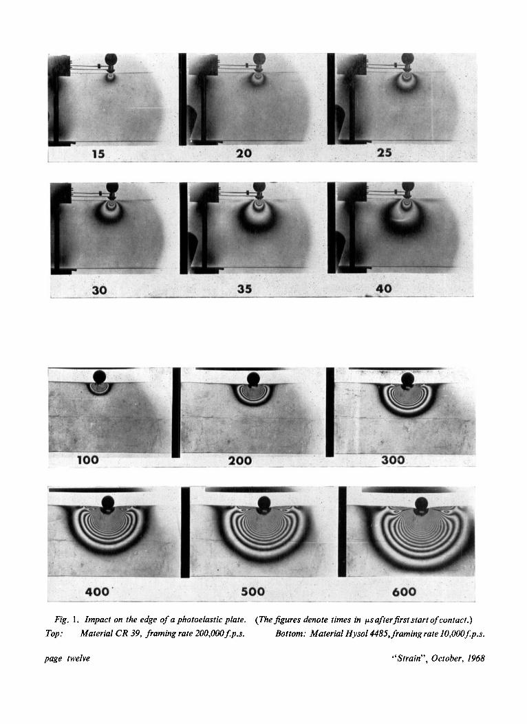
Fig. 1. Impact on the edge of a photoelastic plate. (The figures denote times in psafterfirst start of contact.) Material CR 39, framing rate 200,000$p.s. Top: Bottom: Material Hysol4485, framing rate 10,000Jp.s.
page twelve “Strain”, October, 1968

As the rubber-like consistency of Hysol4485 would have made it difficult to attach to the model the relay contacts used before, a photoelectric gate was mounted in the path of the steel ball. It has been found that the precision of the start signal is much better if the light bulb is supplied with direct current. With this setup the start signal occurred about 4-2 ms before the ball made contact with the model. The times indicated on the pictures are corrected so as to show “real delays” (zero equal to first contact).
It is noteworthy that this time interval as well as the overall duration of the event and other time data important for planning a sequence of images can be estimated quite accurately by directly observing the model in the light of the flashes, thus avoiding time- consuming trial films. The human eye is in fact able to obtain an amazing quantity of information just by looking through the polariscope at the model lit by a single flash lasting less than 1 ps.
If events less suitable for visual inspection have to be photographed, it will be expedient to obtain one or more time histories related to them, for instance by means of oscilloscope-monitored strain gauges.
Bibliography
(1) SENIOR, D. H., WELLS, A. A., “A photoelastic Study of Stress Waves”, Phil. Mag., Series 7 Vol. 37, 1946, p.463
(2) GOLDSMITH, W., NORRIS, G. W., “Stresses in curved beams due to transverse impact”, Proc. 111. U.S. National Congress of Applied Mechanics 1958, p.153.
(3) THORWART, W., “Dynamische Spannungsoptik mit Funkenblitzen”. Bericht ueber den IV Inter- nationalen Kongress fuer Kurzzeitphotographie und Hochfrequenzkinematographie - Verlag Oth- mar Helwich-Darmstadt 1959.
(4) PIRODDA, L., BERBENNI, A. “Metodi sperimentali per lo studio di transitori di deformazione in strutture soggette a carichi dinamici”. Ingegneria Meccanica, Anno XV, N.12, 1966.
(5) TSCHINKE, M. “Studio fotoelastico sui fenomeni transitori all’attacco delle palette di turbomac- chine”. Tecnica Italiana, Rivista di Ingegneria Anno XXXI, N. 11, Novembre, 1966
For all strain gauge problems contact:
STRAINSTALL LIMITED 90a Cowes, Isle of Wight, Tel. Cowes 2219/2360
Recommended