AXIS M5525-E PTZ Network Camera
User Manual
AXIS M5525-E PTZ Network Camera
Table of Contents
Product overview . . . . . . . . . . . . . . . . . . . . . . . . . . . . . . . . . . . . . . . . . . . 3How to connect a microphone to the camera . . . . . . . . . . . . . . . . . . . . 4How to access the product . . . . . . . . . . . . . . . . . . . . . . . . . . . . . . . . . . . . 5
How to access the product from a browser . . . . . . . . . . . . . . . . . . . . . . . . . . . 5About secure passwords . . . . . . . . . . . . . . . . . . . . . . . . . . . . . . . . . . . . . . . . . . 5
Setup . . . . . . . . . . . . . . . . . . . . . . . . . . . . . . . . . . . . . . . . . . . . . . . . . . . . . 7About the product's built-in help . . . . . . . . . . . . . . . . . . . . . . . . . . . . . . . . . . . 7Image quality . . . . . . . . . . . . . . . . . . . . . . . . . . . . . . . . . . . . . . . . . . . . . . . . . . . 7Privacy masks . . . . . . . . . . . . . . . . . . . . . . . . . . . . . . . . . . . . . . . . . . . . . . . . . . 9Overlays . . . . . . . . . . . . . . . . . . . . . . . . . . . . . . . . . . . . . . . . . . . . . . . . . . . . . . . 9PTZ (Pan Tilt Zoom) . . . . . . . . . . . . . . . . . . . . . . . . . . . . . . . . . . . . . . . . . . . . . . 10Streaming and storage . . . . . . . . . . . . . . . . . . . . . . . . . . . . . . . . . . . . . . . . . . . 10Events . . . . . . . . . . . . . . . . . . . . . . . . . . . . . . . . . . . . . . . . . . . . . . . . . . . . . . . . 11Applications . . . . . . . . . . . . . . . . . . . . . . . . . . . . . . . . . . . . . . . . . . . . . . . . . . . . 15
Troubleshooting . . . . . . . . . . . . . . . . . . . . . . . . . . . . . . . . . . . . . . . . . . . . 16How to reset to factory default settings . . . . . . . . . . . . . . . . . . . . . . . . . . . . . 16Check the current firmware . . . . . . . . . . . . . . . . . . . . . . . . . . . . . . . . . . . . . . . 16Upgrade the firmware . . . . . . . . . . . . . . . . . . . . . . . . . . . . . . . . . . . . . . . . . . . . 16Technical issues, clues and solutions . . . . . . . . . . . . . . . . . . . . . . . . . . . . . . . . 17Performance considerations . . . . . . . . . . . . . . . . . . . . . . . . . . . . . . . . . . . . . . . 18
Specifications . . . . . . . . . . . . . . . . . . . . . . . . . . . . . . . . . . . . . . . . . . . . . . 19LED indicators . . . . . . . . . . . . . . . . . . . . . . . . . . . . . . . . . . . . . . . . . . . . . . . . . . 19SD card slot . . . . . . . . . . . . . . . . . . . . . . . . . . . . . . . . . . . . . . . . . . . . . . . . . . . . 19Buttons . . . . . . . . . . . . . . . . . . . . . . . . . . . . . . . . . . . . . . . . . . . . . . . . . . . . . . . 19Connectors . . . . . . . . . . . . . . . . . . . . . . . . . . . . . . . . . . . . . . . . . . . . . . . . . . . . 19
2
AXIS M5525-E PTZ Network Camera
Product overview
Product overview
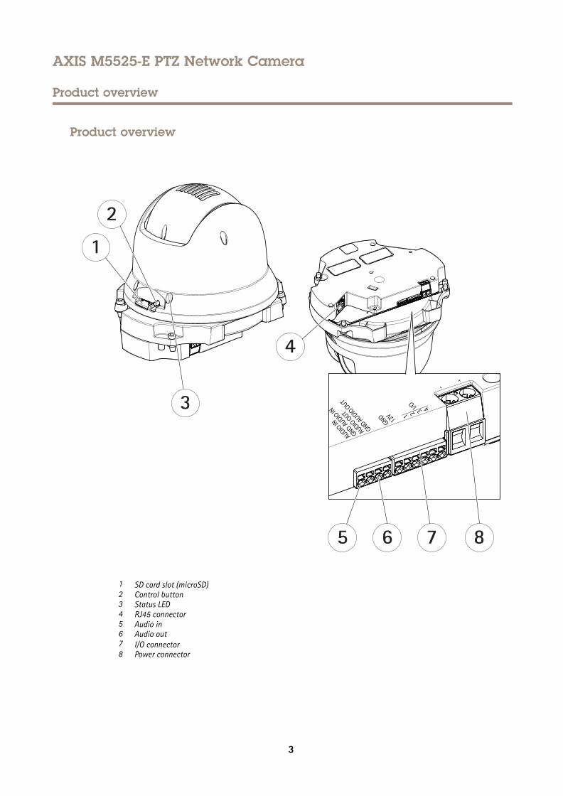
1 SD card slot (microSD)2 Control button3 Status LED4 RJ45 connector5 Audio in6 Audio out7 I/O connector8 Power connector
3
AXIS M5525-E PTZ Network Camera
How to connect a microphone to the camera
How to connect a microphone to the camera
This example explains how to connect a microphone to the camera using an audio extension cable.
Required hardware
• AXIS T8351 Microphone 3.5 mm
• AXIS Audio Extension Cable A, 5 m (16 ft)
Note• To avoid noise, don't run the cable close to or in parallel with other cables.
• To avoid noise, cut the cable as short as possible.
• To maintain IP66 rating, make sure you keep the jack inside the housing.
Connect the cables
1. Keep the 3.5 mm jack and cut the audio extension cable.
2. Strip the outer cable insulation.
3. Strip the inner wire insulation.
4. Twist the audio wires (with insulation) together.
5. Twist the grounding wires (without insulation) together.
6. Connect the audio wires to the AUDIO IN pin on the camera. See Product overview on page 3 .
7. Connect the grounding wires to the GND AUDIO IN pin on the camera.
8. Connect the microphone to the jack of the audio extension cable.
9. Turn on audio and adjust other audio settings in the camera's webpage.
4
AXIS M5525-E PTZ Network Camera
How to access the product
How to access the product
AXIS IP Utility and AXIS Camera Management are recommended methods for finding Axis products on the network and assigningthem IP addresses in Windows®. Both applications are free and can be downloaded from axis.com/support
The product can be used with the following browsers:
• ChromeTM (recommended), Firefox®, Edge®, or Opera® with Windows®
• ChromeTM (recommended) or Safari® with OS X®
• ChromeTM or Firefox® with other operating systems.
If you need more information about recommended browsers, go to axis.com/browser-support
How to access the product from a browser1. Start a web browser.
2. Enter the IP address or host name of the Axis product in the browser’s address field.
To access the product from a Mac computer (OS X), go to Safari, click on Bonjour and select the product from thedrop-down list. To add Bonjour as a browser bookmark, go to Safari > Preferences.
If you do not know the IP address, use AXIS IP Utility to locate the product on the network. For information abouthow to discover and assign an IP address, see the document Assign an IP Address and Access the Video Stream on AxisSupport web at axis.com/support
3. Enter your username and password. If this is the first time the product is accessed, the root password must first beconfigured.
4. The product’s live view page opens in your browser.
About secure passwordsImportant
Axis devices send the initially set password in clear text over the network. To protect your device after the first login, setup a secure and encrypted HTTPS connection and then change the password.
The device password is the primary protection for the data and services. Axis devices do not impose a password policy as they may beused in various types of installations. To protect your data we recommend that you:
• Change the default password that comes with the devices.
• Use a password with at least 8 characters, preferably created by a password generator.
• Don’t expose the password.
• Change password at a recurring interval, at least once a year.
Set a secure password for the root account
ImportantThe default administrator user name root cannot be deleted. If the password for root is lost, the device must be reset tothe factory default settings.
1. Make sure to follow the instructions about secure passwords. See About secure passwords on page 5 .
2. Type a password and then retype it to confirm the spelling.
5

AXIS M5525-E PTZ Network Camera
How to access the product
3. Click Create login. The password has now been configured.
6
AXIS M5525-E PTZ Network Camera
Setup
Setup
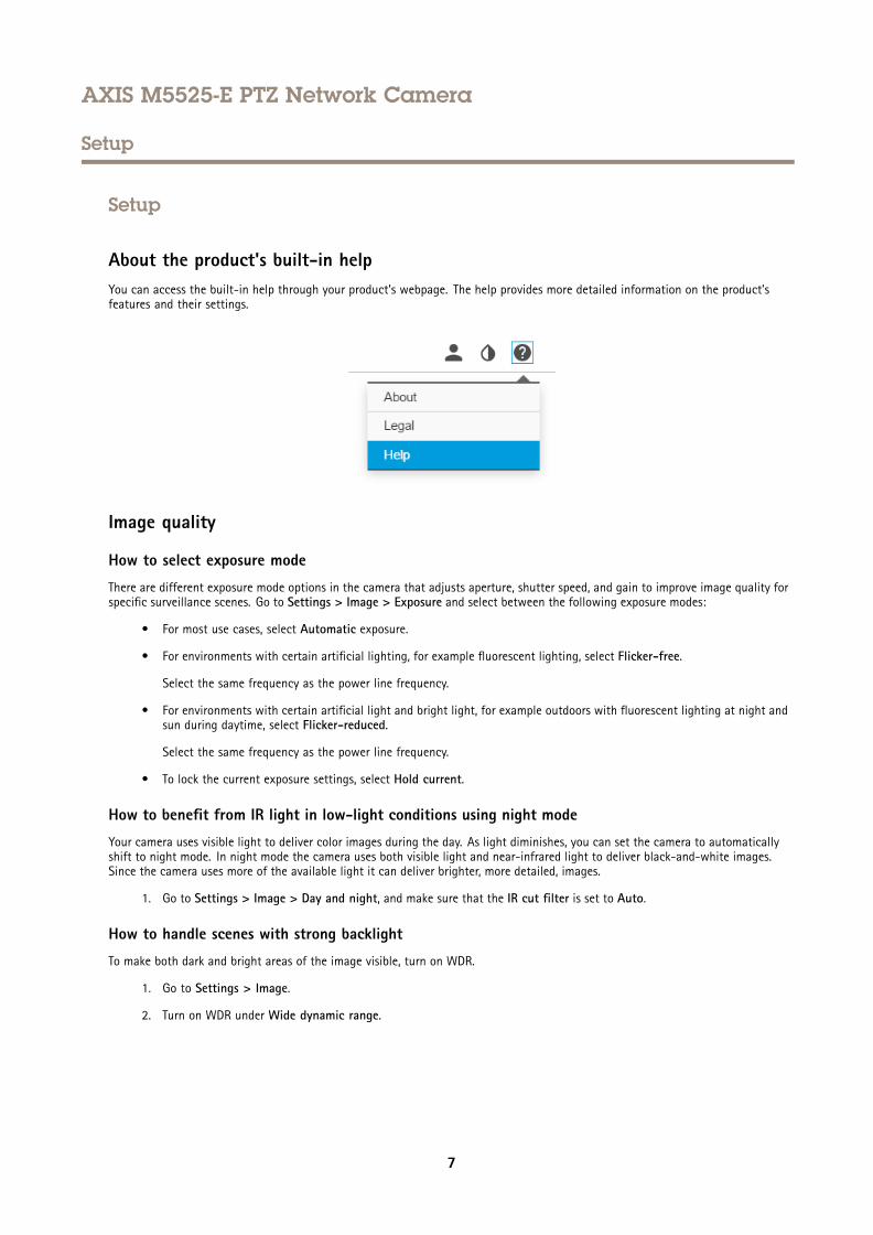
About the product's built-in helpYou can access the built-in help through your product’s webpage. The help provides more detailed information on the product’sfeatures and their settings.
Image quality
How to select exposure mode
There are different exposure mode options in the camera that adjusts aperture, shutter speed, and gain to improve image quality forspecific surveillance scenes. Go to Settings > Image > Exposure and select between the following exposure modes:
• For most use cases, select Automatic exposure.
• For environments with certain artificial lighting, for example fluorescent lighting, select Flicker-free.
Select the same frequency as the power line frequency.
• For environments with certain artificial light and bright light, for example outdoors with fluorescent lighting at night andsun during daytime, select Flicker-reduced.
Select the same frequency as the power line frequency.
• To lock the current exposure settings, select Hold current.
How to benefit from IR light in low-light conditions using night mode
Your camera uses visible light to deliver color images during the day. As light diminishes, you can set the camera to automaticallyshift to night mode. In night mode the camera uses both visible light and near-infrared light to deliver black-and-white images.Since the camera uses more of the available light it can deliver brighter, more detailed, images.
1. Go to Settings > Image > Day and night, and make sure that the IR cut filter is set to Auto.
How to handle scenes with strong backlight
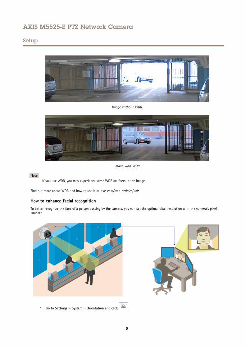
To make both dark and bright areas of the image visible, turn on WDR.
1. Go to Settings > Image.
2. Turn on WDR under Wide dynamic range.
7
AXIS M5525-E PTZ Network Camera
Setup
Image without WDR.
Image with WDR.
NoteIf you use WDR, you may experience some WDR artifacts in the image.
Find out more about WDR and how to use it at axis.com/web-articles/wdr
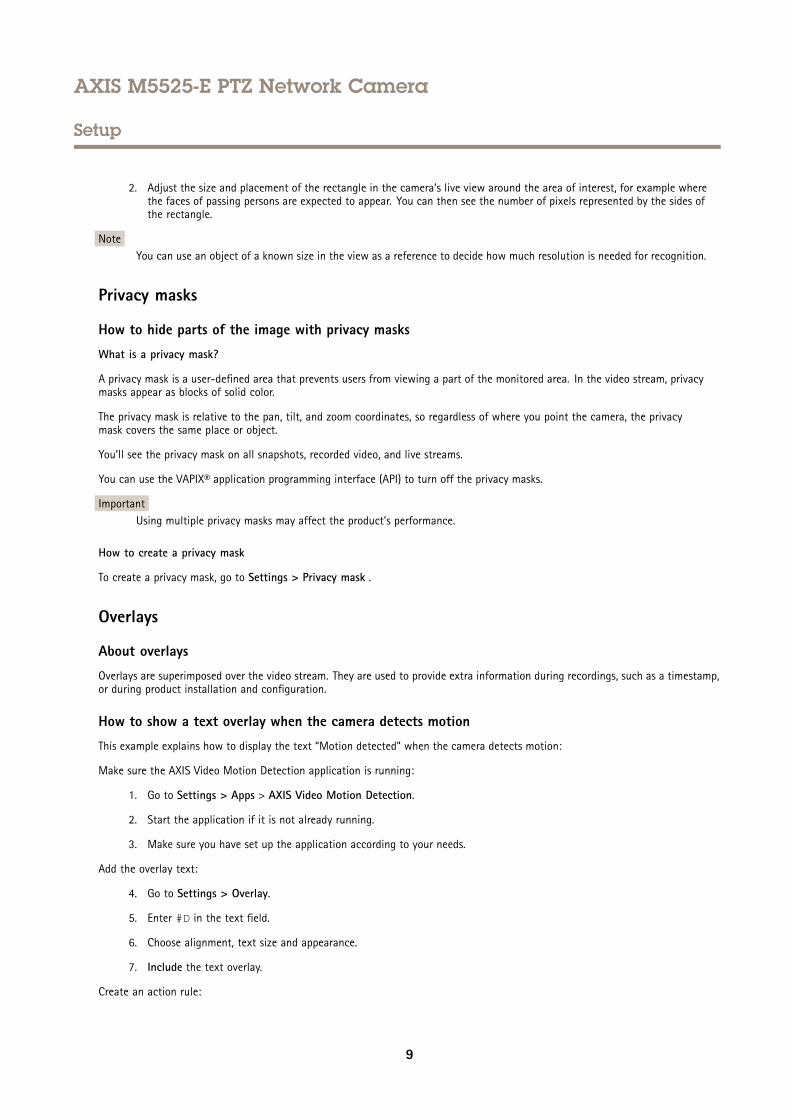
How to enhance facial recognition
To better recognize the face of a person passing by the camera, you can set the optimal pixel resolution with the camera’s pixelcounter.
1. Go to Settings > System > Orientation and click .
8
AXIS M5525-E PTZ Network Camera
Setup
2. Adjust the size and placement of the rectangle in the camera’s live view around the area of interest, for example wherethe faces of passing persons are expected to appear. You can then see the number of pixels represented by the sides ofthe rectangle.
NoteYou can use an object of a known size in the view as a reference to decide how much resolution is needed for recognition.
Privacy masks
How to hide parts of the image with privacy masks
What is a privacy mask?
A privacy mask is a user-defined area that prevents users from viewing a part of the monitored area. In the video stream, privacymasks appear as blocks of solid color.
The privacy mask is relative to the pan, tilt, and zoom coordinates, so regardless of where you point the camera, the privacymask covers the same place or object.
You’ll see the privacy mask on all snapshots, recorded video, and live streams.
You can use the VAPIX® application programming interface (API) to turn off the privacy masks.
ImportantUsing multiple privacy masks may affect the product’s performance.
How to create a privacy mask
To create a privacy mask, go to Settings > Privacy mask .
Overlays
About overlays
Overlays are superimposed over the video stream. They are used to provide extra information during recordings, such as a timestamp,or during product installation and configuration.
How to show a text overlay when the camera detects motion
This example explains how to display the text “Motion detected” when the camera detects motion:
Make sure the AXIS Video Motion Detection application is running:
1. Go to Settings > Apps > AXIS Video Motion Detection.
2. Start the application if it is not already running.
3. Make sure you have set up the application according to your needs.
Add the overlay text:
4. Go to Settings > Overlay.
5. Enter #D in the text field.
6. Choose alignment, text size and appearance.
7. Include the text overlay.
Create an action rule:
9
AXIS M5525-E PTZ Network Camera
Setup
8. Go to System > Events > Action rules.
9. Create an action rule with AXIS Video Motion Detection as trigger.
10. From the list of actions, select Overlay text.
11. Type “Motion detected”.
12. Set the duration.
NoteIf you update the overlay text it will be automatically updated on all video streams dynamically.
PTZ (Pan Tilt Zoom)
How to limit pan, tilt, and zoom movements
In this example, the camera is surveilling a parking lot with nearby apartment buildings. Set pan, tilt and zoom limits to ensureprivacy for residents.
To limit pan, tilt and zoom movements, go to Settings > PTZ > Limits.
Streaming and storage
How to choose video compression format
Decide which compression method to use based on your viewing requirements, and on the properties of your network. Theavailable options are:
Motion JPEG
Motion JPEG or MJPEG is a digital video sequence that is made up of a series of individual JPEG images. These images are thendisplayed and updated at a rate sufficient to create a stream that shows constantly updated motion. For the viewer to perceive motionvideo the rate must be at least 16 image frames per second. Full motion video is perceived at 30 (NTSC) or 25 (PAL) frames per second.
The Motion JPEG stream uses considerable amounts of bandwidth, but provides excellent image quality and access to every imagecontained in the stream.
H.264 or MPEG-4 Part 10/AVC
NoteH.264 is a licensed technology. The Axis product includes one H.264 viewing client license. Installing additional unlicensedcopies of the client is prohibited. To purchase additional licenses, contact your Axis reseller.
H.264 can, without compromising image quality, reduce the size of a digital video file by more than 80% compared to the MotionJPEG format and by as much as 50% compared to the MPEG-4 standard. This means that less network bandwidth and storage spaceare required for a video file. Or seen another way, higher video quality can be achieved for a given bitrate.
How to reduce bandwidth and storage
ImportantIf you reduce the bandwidth it can result in loss of details in the picture.
1. Go to live view and select H.264.
2. Go to Settings > Stream.
3. Do one or more of the following:
10
AXIS M5525-E PTZ Network Camera
Setup
- Turn on the Zipstream functionality and select the desired level.
- Turn on dynamic GOP and set a high GOP length value.
- Increase the compression.
- Turn on dynamic FPS.
How to set up network storage
To store recordings on the network, you need to set up network storage:
1. Go to Settings > System > Storage.
2. Click Setup under Network storage.
3. Enter the IP address of the host server.
4. Enter the name of the shared location on the host server.
5. Move the switch if the share requires a login, and enter username and password.
6. Click Connect.
How to add audio to your recording
Edit the stream profile which is used for the recording:
1. Go to Settings > System > Stream profiles.
2. Select the stream profile and click Modify.
3. In the Audio tab, select the Audio stream checkbox and select On from the drop-down list.
4. Click Ok.
Events
About events
The event pages allow you to configure your product to perform actions when different events occur. For example, the productcan start a recording or send an email notification when motion is detected. The set of conditions that defines how and whenthe action is triggered is called an action rule.
How to direct the camera to a preset position when the camera detects motion
This example explains how to set up the camera to go to a preset position when it detects motion in the image.
Make sure the AXIS Video Motion Detection application is running:
1. Go to Settings > Apps > AXIS Video Motion Detection.
2. Start the application if it is not already running.
3. Make sure you have set up the application according to your needs.
Add a preset position:
4. Go to Settings > PTZ and set where you want the camera to be directed by creating a preset position.
Create an action rule:
5. Go to Settings > System > Events > Action rules and add an action rule.
11
AXIS M5525-E PTZ Network Camera
Setup
6. Type a name for the action rule.
7. From the list of triggers, select Applications and then select AXIS Video Motion Detection (VMD).
8. From the list of actions, select PTZ Control and then select Preset Position.
9. Select the preset position you want the camera to go to.
10. Click Ok.
How to record video when a PIR detector senses motion
This example explains how to connect an Axis PIR detector to the camera, and set up the camera to start recording when thedetector senses motion.
Required hardware
• 3–wire cable (ground, power, I/O)
• Axis PIR detector
NONONOTICETICETICEDisconnect the camera from power before connecting the wires. Reconnect to power after all connections are done.
Connect the wires to the camera’s I/O connector
NoteFor information on the I/O connector, see Connectors on page 19
1. Connect the ground wire to pin 1 (GND/-).
2. Connect the power wire to pin 2 (12V DC output).
3. Connect the I/O wire to pin 3 (I/O input).
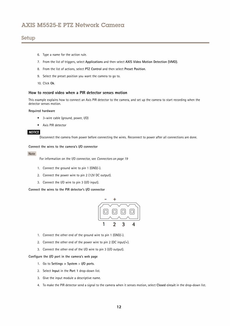
Connect the wires to the PIR detector’s I/O connector
1. Connect the other end of the ground wire to pin 1 (GND/-).
2. Connect the other end of the power wire to pin 2 (DC input/+).
3. Connect the other end of the I/O wire to pin 3 (I/O output).
Configure the I/O port in the camera’s web page
1. Go to Settings > System > I/O ports.
2. Select Input in the Port 1 drop-down list.
3. Give the input module a descriptive name.
4. To make the PIR detector send a signal to the camera when it senses motion, select Closed circuit in the drop-down list.
12
AXIS M5525-E PTZ Network Camera
Setup
To trigger the camera to start recording when it receives a signal from the PIR detector, you need to create an action rule in thecamera’s web page.
Use audio to deter intruders
This example explains how to connect a speaker to the camera and set it up to play a warning message when the camera detectsmotion in a restricted area.
Required hardware
• Active speaker with built-in amplifier and connecting wires
NONONOTICETICETICEMake sure the camera is disconnected from power before making the connections. Reconnect to power after connecting thewires.
Physical connection
1. Connect the audio wire from the speaker to the AUDIO OUT pin on the camera. See Product overview on page 3 .
2. Connect the grounding wire from the speaker to the GND AUDIO OUT pin on the camera. See Product overview on page 3 .
Add audio clip to the camera
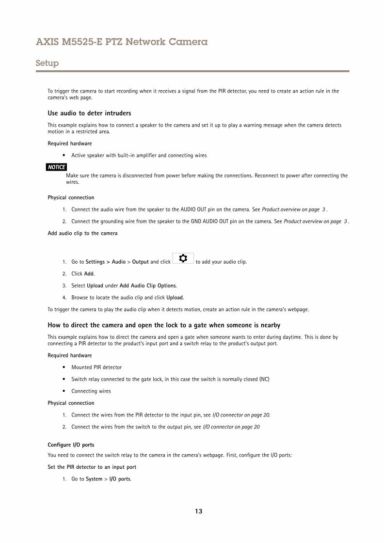
1. Go to Settings > Audio > Output and click to add your audio clip.
2. Click Add.
3. Select Upload under Add Audio Clip Options.
4. Browse to locate the audio clip and click Upload.
To trigger the camera to play the audio clip when it detects motion, create an action rule in the camera’s webpage.
How to direct the camera and open the lock to a gate when someone is nearby
This example explains how to direct the camera and open a gate when someone wants to enter during daytime. This is done byconnecting a PIR detector to the product’s input port and a switch relay to the product’s output port.
Required hardware
• Mounted PIR detector
• Switch relay connected to the gate lock, in this case the switch is normally closed (NC)
• Connecting wires
Physical connection
1. Connect the wires from the PIR detector to the input pin, see I/O connector on page 20.
2. Connect the wires from the switch to the output pin, see I/O connector on page 20
Configure I/O ports
You need to connect the switch relay to the camera in the camera’s webpage. First, configure the I/O ports:
Set the PIR detector to an input port
1. Go to System > I/O ports.
13
AXIS M5525-E PTZ Network Camera
Setup
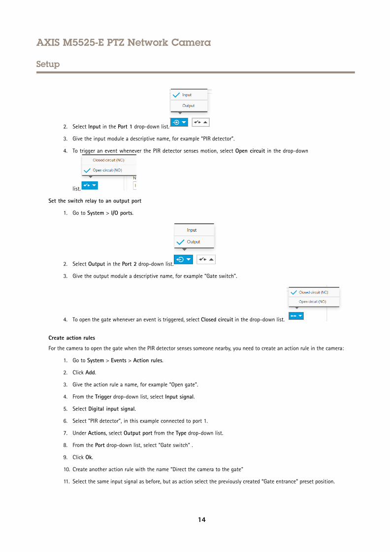
2. Select Input in the Port 1 drop-down list.
3. Give the input module a descriptive name, for example “PIR detector”.
4. To trigger an event whenever the PIR detector senses motion, select Open circuit in the drop-down
list.
Set the switch relay to an output port
1. Go to System > I/O ports.
2. Select Output in the Port 2 drop-down list.
3. Give the output module a descriptive name, for example “Gate switch”.
4. To open the gate whenever an event is triggered, select Closed circuit in the drop-down list.
Create action rules
For the camera to open the gate when the PIR detector senses someone nearby, you need to create an action rule in the camera:
1. Go to System > Events > Action rules.
2. Click Add.
3. Give the action rule a name, for example “Open gate”.
4. From the Trigger drop-down list, select Input signal.
5. Select Digital input signal.
6. Select ”PIR detector”, in this example connected to port 1.
7. Under Actions, select Output port from the Type drop-down list.
8. From the Port drop-down list, select “Gate switch” .
9. Click Ok.
10. Create another action rule with the name “Direct the camera to the gate"
11. Select the same input signal as before, but as action select the previously created “Gate entrance” preset position.
14
AXIS M5525-E PTZ Network Camera
Setup
12. Click Ok.
Applications
About applications
AXIS Camera Application Platform (ACAP) is an open platform that enables third parties to develop analytics and other applicationsfor Axis products. To find out more about available applications, downloads, trials and licenses, go to axis.com/applications
To find the user manuals for Axis applications, go to axis.com
Note• Several applications can run at the same time but some applications might not be compatible with each other. Certain
combinations of applications might require too much processing power or memory resources when run in parallel. Verifythat the applications work together before deployment.
15
AXIS M5525-E PTZ Network Camera
Troubleshooting
Troubleshooting
How to reset to factory default settingsImportant
Reset to factory default should be used with caution. A reset to factory default resets all settings, including the IP address, tothe factory default values.
To reset the product to the factory default settings:
1. Disconnect power from the product.
2. Press and hold the control button while reconnecting power. See Product overview on page 3 .
3. Keep the control button pressed for 15–30 seconds until the status LED indicator flashes amber.
4. Release the control button. The process is complete when the status LED indicator turns green. The product has been resetto the factory default settings. If no DHCP server is available on the network, the default IP address is 192.168.0.90
5. Use the installation and management software tools to assign an IP address, set the password, and access the video stream.
The installation and management software tools are available from the support pages on axis.com/support
It is also possible to reset parameters to factory default via the web interface. Go to Settings > System > Maintenance andclick Default.
Check the current firmwareFirmware is the software that determines the functionality of network devices. One of your first actions when troubleshooting aproblem should be to check the current firmware version. The latest version may contain a correction that fixes your particularproblem.
To check the current firmware:
1. Go to the product’s webpage.
2. Click on the help menu .
3. Click About.
Upgrade the firmwareImportant
Preconfigured and customized settings are saved when the firmware is upgraded (provided that the features are available inthe new firmware) although this is not guaranteed by Axis Communications AB.
ImportantMake sure the product remains connected to the power source throughout the upgrade process.
NoteWhen you upgrade the product with the latest firmware in the active track, the product receives the latest functionalityavailable. Always read the upgrade instructions and release notes available with each new release before upgrading thefirmware. To find the latest firmware and the release notes, go to axis.com/support/firmware.
1. Download the firmware file to your computer, available free of charge at axis.com/support/firmware.
16
AXIS M5525-E PTZ Network Camera
Troubleshooting
2. Log in to the product as an administrator.
3. Go to Settings > System > Maintenance. Follow the instructions on the page. When the upgrade has finished, theproduct restarts automatically.
AXIS Device Manager can be used for multiple upgrades. Find out more at axis.com/products/axis-device-manager.
Technical issues, clues and solutionsIf you can’t find what you’re looking for here, try the troubleshooting section at axis.com/support
Problems upgrading the firmware
Firmware upgrade failure If the firmware upgrade fails, the product reloads the previous firmware. The most common reasonis that the wrong firmware file has been uploaded. Check that the name of the firmware filecorresponds to your product and try again.
Problems setting the IP address
The product is located on adifferent subnet
If the IP address intended for the product and the IP address of the computer used to access theproduct are located on different subnets, you cannot set the IP address. Contact your networkadministrator to obtain an IP address.
The IP address is being usedby another device
Disconnect the Axis product from the network. Run the ping command (in a Command/DOSwindow, type ping and the IP address of the product):
• If you receive: Reply from <IP address>: bytes=32; time=10...this means that the IP address may already be in use by another device on the network.Obtain a new IP address from the network administrator and reinstall the product.
• If you receive: Request timed out, this means that the IP address is availablefor use with the Axis product. Check all cabling and reinstall the product.
Possible IP address conflictwith another device on thesame subnet
The static IP address in the Axis product is used before the DHCP server sets a dynamic address.This means that if the same default static IP address is also used by another device, there maybe problems accessing the product.
The product cannot be accessed from a browser
Cannot log in When HTTPS is enabled, ensure that the correct protocol (HTTP or HTTPS) is used when attemptingto log in. You may need to manually type http or https in the browser’s address field.
If the password for the user root is lost, the product must be reset to the factory default settings.See How to reset to factory default settings on page 16.
The IP address has beenchanged by DHCP
IP addresses obtained from a DHCP server are dynamic and may change. If the IP address hasbeen changed, use AXIS IP Utility or AXIS Camera Management to locate the product on thenetwork. Identify the product using its model or serial number, or by the DNS name (if the namehas been configured).
If required, a static IP address can be assigned manually. For instructions, go to axis.com/support
Certificate error when usingIEEE 802.1X
For authentication to work properly, the date and time settings in the Axis product must besynchronized with an NTP server. Go to Settings > System > Date and time
The product is accessible locally but not externally
Router configuration Check that your router allows incoming data traffic to the Axis product. The router must supportUPnP®.
Firewall protection Check the Internet firewall with your network administrator.
17
AXIS M5525-E PTZ Network Camera
Troubleshooting
Problems with streaming
Multicast H.264 onlyaccessible by local clients
Check if your router supports multicasting, or if the router settings between the client and theproduct need to be configured. The TTL (Time To Live) value may need to be increased.
No multicast H.264displayed in the client
Check with your network administrator that the multicast addresses used by the Axis productare valid for your network.
Check with your network administrator to see if there is a firewall preventing viewing.
Poor rendering of H.264images
Ensure that your graphics card is using the latest driver. The latest drivers can usually bedownloaded from the manufacturer’s website.
Color saturation is differentin H.264 and Motion JPEG
Modify the settings for your graphics adapter. Go to the adapter’s documentation for moreinformation.
Lower frame rate thanexpected
• See Performance considerations on page 18.• Reduce the number of applications running on the client computer.• Limit the number of simultaneous viewers.• Check with the network administrator that there is enough bandwidth available.• Lower the image resolution.• In the product’s webpage, set a capture mode that prioritizes frame rate. Changing the
capture mode to prioritize frame rate might lower the maximum resolution dependingon the product used and capture modes available.
Performance considerationsWhen setting up your system, it is important to consider how various settings and situations affect the performance. Some factorsaffect the amount of bandwidth (the bitrate) required, others can affect the frame rate, and some affect both. If the load on theCPU reaches its maximum, this also affects the frame rate.
The following factors are the most important to consider:
• High image resolution or lower compression levels result in images containing more data which in turn affects thebandwidth.
• Access by large numbers of Motion JPEG or unicast H.264 clients affects the bandwidth.
• Simultaneous viewing of different streams (resolution, compression) by different clients affects both frame rate andbandwidth.
Use identical streams wherever possible to maintain a high frame rate. Stream profiles can be used to ensure thatstreams are identical.
• Accessing Motion JPEG and H.264 video streams simultaneously affects both frame rate and bandwidth.
• Heavy usage of event settings affects the product’s CPU load which in turn affects the frame rate.
• Using HTTPS may reduce frame rate, in particular if streaming Motion JPEG.
• Heavy network utilization due to poor infrastructure affects the bandwidth.
• Viewing on poorly performing client computers lowers perceived performance and affects frame rate.
• Running multiple AXIS Camera Application Platform (ACAP) applications simultaneously may affect the frame rate andthe general performance.
18
AXIS M5525-E PTZ Network Camera
Specifications
Specifications
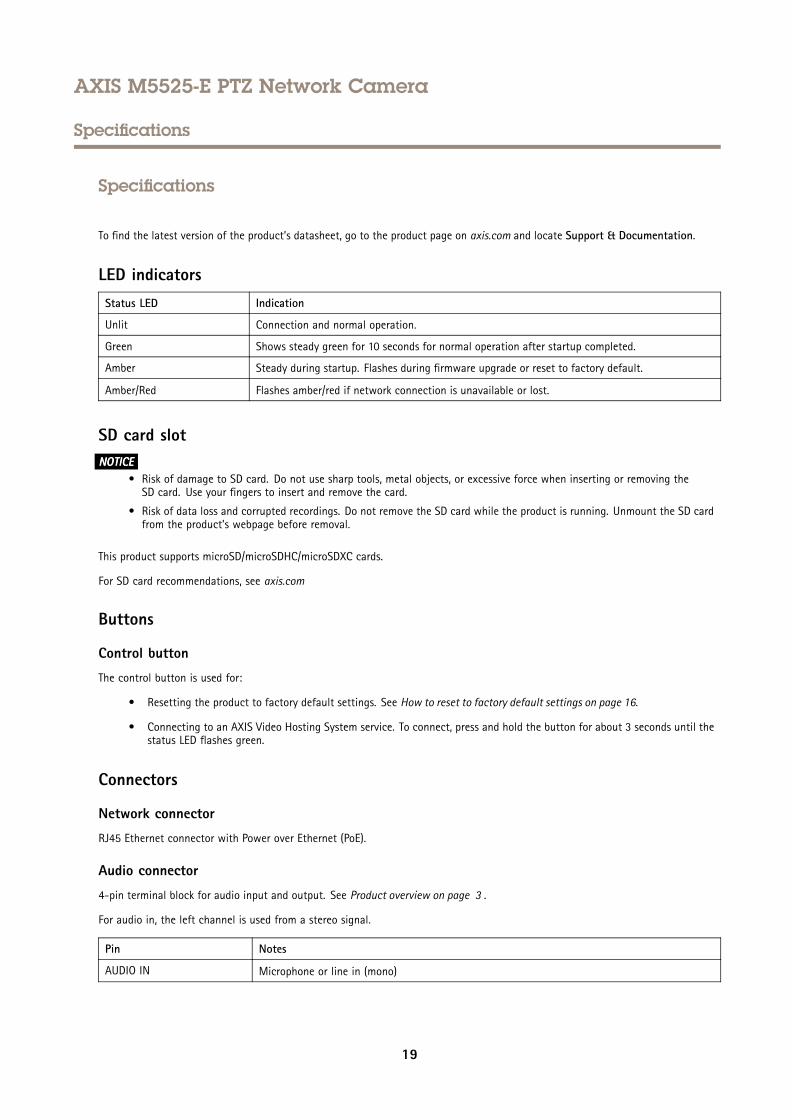
To find the latest version of the product’s datasheet, go to the product page on axis.com and locate Support & Documentation.
LED indicatorsStatus LED Indication
Unlit Connection and normal operation.
Green Shows steady green for 10 seconds for normal operation after startup completed.
Amber Steady during startup. Flashes during firmware upgrade or reset to factory default.
Amber/Red Flashes amber/red if network connection is unavailable or lost.
SD card slotNONONOTICETICETICE
• Risk of damage to SD card. Do not use sharp tools, metal objects, or excessive force when inserting or removing theSD card. Use your fingers to insert and remove the card.
• Risk of data loss and corrupted recordings. Do not remove the SD card while the product is running. Unmount the SD cardfrom the product’s webpage before removal.
This product supports microSD/microSDHC/microSDXC cards.
For SD card recommendations, see axis.com
Buttons
Control button
The control button is used for:
• Resetting the product to factory default settings. See How to reset to factory default settings on page 16.
• Connecting to an AXIS Video Hosting System service. To connect, press and hold the button for about 3 seconds until thestatus LED flashes green.
Connectors
Network connector
RJ45 Ethernet connector with Power over Ethernet (PoE).
Audio connector
4-pin terminal block for audio input and output. See Product overview on page 3 .
For audio in, the left channel is used from a stereo signal.
Pin Notes
AUDIO IN Microphone or line in (mono)
19
AXIS M5525-E PTZ Network Camera
Specifications
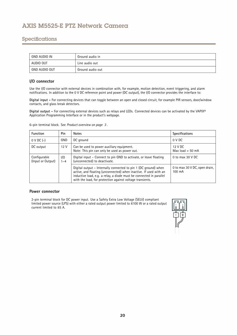
GND AUDIO IN Ground audio in
AUDIO OUT Line audio out
GND AUDIO OUT Ground audio out
I/O connector
Use the I/O connector with external devices in combination with, for example, motion detection, event triggering, and alarmnotifications. In addition to the 0 V DC reference point and power (DC output), the I/O connector provides the interface to:
Digital input - For connecting devices that can toggle between an open and closed circuit, for example PIR sensors, door/windowcontacts, and glass break detectors.
Digital output - For connecting external devices such as relays and LEDs. Connected devices can be activated by the VAPIX®Application Programming Interface or in the product’s webpage.
6–pin terminal block. See Product overview on page 3 .
Function Pin Notes Specifications
0 V DC (-) GND DC ground 0 V DC
DC output 12 V Can be used to power auxiliary equipment.Note: This pin can only be used as power out.
12 V DCMax load = 50 mA
Digital input – Connect to pin GND to activate, or leave floating(unconnected) to deactivate.
0 to max 30 V DCConfigurable(Input or Output)
I/O1–4
Digital output – Internally connected to pin 1 (DC ground) whenactive, and floating (unconnected) when inactive. If used with aninductive load, e.g. a relay, a diode must be connected in parallelwith the load, for protection against voltage transients.
0 to max 30 V DC, open drain,100 mA
Power connector
2-pin terminal block for DC power input. Use a Safety Extra Low Voltage (SELV) compliantlimited power source (LPS) with either a rated output power limited to ≤100 W or a rated outputcurrent limited to ≤5 A.
20

User Manual Ver. M4.2AXIS M5525-E PTZ Network Camera Date: March 2020© Axis Communications AB, 2017 - 2020 Part No. T10111798
Recommended

![microSD-CONF 1 タヴシクヴダ · 2011-08-08 · 1 or 8 bit幅 エリア設定 ロータリSW ①microSD => FPGA直接転送モード microSD microSD-CONF1 XMODE XAREA[3:0] 図1-1.uSD-CONF1](https://img.pdfslide.net/doc/110x75/5f30bf189d8acd0cba350893/microsd-conf-1-fff-2011-08-08-1-or-8-bit-iiie-iiiisw.jpg)