Ball Juggling on the Bipedal Robot Cassie
Katherine L. Poggensee*, Albert H. Li*, Daniel Sotsaikich*,Bike Zhang, Prasanth Kotaru, Mark Mueller, Koushil Sreenath
Abstract— The increasing integration of robots in daily lifenecessitates research in multitasking strategies. The act ofjuggling offers a simple platform to test techniques which maybe generalizable to more complex tasks and systems. This paperpresents both analytical and empirical results for successfulball-juggling on the bipedal robotic research platform Cassie.A control strategy inspired by mirror law algorithms was sim-ulated on a simple paddle-ball system and then extended to theCassie-ball system in simulations and experiments, using twolow-level control schemes. A Poincare analysis demonstratedstability for both controllers. Both simulated and experimentalresults show that the proposed strategy is robust to a widerange of physical parameters and that the act of juggling whilebalancing is achievable through multiple methods.
I. INTRODUCTION
A. Motivation
As autonomous systems are integrated into daily life, theability to safely and accurately perform complex dynamicaltasks in uncertain environments becomes increasingly essen-tial. The difficulty in simultaneously completing these taskswhile also maintaining the safety of robots, humans, and thesurrounding environment has acted as a barrier to the wideradoption of robotic technology, especially for mobile robotswith the potential to cause injury or damage.
In light of these motivations, juggling can be a usefultask to study. Unlike prehensile catching, juggling requiresinteraction with an object in free fall and repeated redirectionof its trajectory to maintain a periodic orbit. The repeatedinteractions between the ball and robot can also affect thestability of the robot itself. Thus, juggling may provide usefulanalogues for more generalizable methods for dynamicalmultitasking in collaborative or populated environments.
B. Related Work
The simplest juggling system, a ball and a fixed planarpaddle, has been used to develop controllers that oftenexhibit juggling motions similar to those observed in skilledhuman jugglers [2], [14]. These techniques have been furtherextended to 3-dimensional juggling [12], juggling of multipleballs [11], and open-loop juggling through clever design ofa paddle with curved geometry [10].
* These authors contributed equally to this work.K. L. Poggensee, A. H. Li, and D. Sotsaikich are with the Depart-ment of Mechanical Engineering, Stanford University, CA, 94305, USA,ktpognc, ahli, [email protected]. Zhang, P. Kotaru, M. Mueller, and K. Sreenath are with the De-partment of Mechanical Engineering, University of California, Berkeley,CA, 94720, USA, bikezhang, prasanth.kotaru, mwm,[email protected].
Fig. 1. Snapshots of experiments on the Cassie-paddle-ball system. Twojuggles, shown here, take 0.6 sec per bounce on average. Experimentalvideos are accessible at https://hybrid-robotics.berkeley.edu/cassie-juggling.
While the paddle-ball system is effective for studyingthe dynamics of ball bouncing, it is limited to the task ofjuggling. Recent work with robotic juggling has incorporatedrobots not designed specifically for this task. Quadrotors [7],[4], one degree-of-freedom robots [15], and robotic arms [13]have been used to juggle independently as well as coopera-tively. Unlike the fixed-base robot in [13], quadrotor jugglingcontrol has the added complexity of maintaining its heightwhile bouncing the ball along the desired trajectory.
C. Contributions
The focus of this paper is the implementation of jugglingcontrol strategies on the underactuated, bipedal robotic re-search platform Cassie, built by Agility Robotics. Cassie hasbeen shown to be capable of performing highly dynamicaltasks, e.g., walking on different terrains [5] and movingon hovershoes [3]. For this problem, Cassie must maintainbalance while juggling using the same set of actuators. Thecontributions of this paper with respect to prior work are:• the characterization of the system governing the inter-
actions between the ball and robot-paddle system,• stability analysis validating the controller designs,• simulation of the robot-ball system using optimization-
based and PD-based approaches to simultaneously bal-ance on two feet while juggling, and
• experiments demonstrating the validity of the controller.
D. Organization
The paper is organized as follows. Section II introduces thedynamical models for a simple paddle-ball system which isthen extended to the robot-ball system. Section III presentsthe controller design and describes two methods for main-taining balance while juggling, followed by an analysis ofthe controller stability in Section IV. Section V summarizessimulation results for both balance methods. Section VIdetails experiments on Cassie using one of the presentedjuggling controllers and analyzes deviations from the mod-eled behavior. The final section (VII) lists shortcomings withthe current implementation, conclusions, and future work.
II. HYBRID DYNAMICAL MODEL FOR JUGGLING
In this section, the dynamics for two systems – a simplepaddle-ball and the Cassie-ball system – are described. Thepaddle-ball system was used to test the efficacy of thecontroller on a more intuitive platform, while the Cassie-ballsystem provided a realistic model for experiments.
A. Simple Paddle-Ball Model
The paddle was modeled as a floating rectangular rigid bodyin SE(3) and the ball as a point mass in R3. The ball heightand velocity relative to the paddle frame, ζb, ζb ∈ R, are
ζb = (xb − xp)>Re3 (1)
ζb =(
(xb − xp)>R + (xb − xp)>RΩ)
e3, (2)
where xb,xp ∈ R3 are the Cartesian positions of the ball andpaddle respectively, R ∈ SO(3) is the rotation matrix fromthe paddle to the world frame, Ω ∈ R3 is the paddle angularvelocity vector, · : R3 → SO(3) is the skew-symmetricoperator, and e3 ∈ R3 is the third canonical basis vector.
Contact occurs at the surface where ζp ≡ 0 and caneither be modeled as an instantaneous, rigid contact oras a compliant-contact model. While instantaneous contactmodels motivated the control architecture used in this paper,compliant contact better represents experimental conditions.
The compliant contact between the paddle and ball wasmodeled as a mass-spring-damper system. If ζp > 0, nocontact occurs, and the ball is only subject to gravitationalforces. Adapting the methods in [1], the force on the ball inthe paddle frame is given by
fn,b =√
max−ζp, 0 (−Gkζp −Gbζp) e3, (3)
where Gk, Gb are the paddle stiffness and damping coef-ficients. Contact is assumed to be frictionless because theexpected lateral speed and rotation of the paddle were limitedby the controller. The contact also results in an equal andopposite force, −fn,b, on the paddle as well as the inducedmoment, −R>(xb − xp)× fn,b.
Thus, for paddle inputs f ,M ∈ R3 and the contact modelfrom (3), the paddle-ball model is compactly written as
Σpb :
mbxb = Rfn,b −mbge3
mpxp = −Rfn,b + f −mpge3
JpΩ = −R>(xb − xp)× fn,b+ M−Ω× JpΩ,
(4)
where Jp is the paddle inertia matrix, mp,mb the paddle andball masses, and g the gravitational acceleration constant.
B. Full Robot-Ball Model
The dynamical model of Cassie is described in detail in [5].The generalized coordinates contain the position and orien-tation of the pelvis and the angular positions of the sevenjoints for the left and right legs, respectively, written as
qrobot := [qx, qy, qz, qyaw, qpitch, qroll,
q1L, q2L, q3L, q4L, q5L, q6L, q7L,
q1R, q2R, q3R, q4R, q5R, q6R, q7R]>.
(5)
The seven joint coordinates refer to the hip roll, hip yaw,hip pitch, knee pitch, shin pitch, tarsus pitch, and toe pitchrespectively. Only q1, q2, q3, q4, and q7 are actuated, whileq5 and q6 are passive, moving subject to springs in the leg.
Cassie is modeled with two contact points per foot, wherethe force at each point is modeled like the stick/slip modelin [1]. The normal ground deformation during contact, ζg ,is defined similarly to ζp in the paddle-ball model. Themagnitude of the foot-ground contact force, fn,g , is likewisecomputed similarly to ‖fn,b‖.
For ground stiffness and damping coefficients Γk,Γb,tangential ground deformation ξg , coefficient of friction µ,and planar foot velocity xfoot ∈ R2, the stick/slip forcestangential to the ground are fstick, fslip ∈ R2, given by
fstick =√
max−ζg, 0 (−Γkξg − Γbxfoot) (6)
fslip = fstick ×µfn,g‖fstick‖
, (7)
where fslip is only computed for nonzero fstick. The fric-tional force ffriction = fslip when ||fstick|| > µfn,g , andffriction = fstick otherwise. The total contact force is then
fC =
[ffriction
fn,g
]. (8)
Because the paddle was mounted rigidly to Cassie’s pelvis,the transformation from the robot to the paddle is known andthe paddle-ball model was easily integrated with the robotmodel. Thus, using the same implicit switching condition asin (4), the complete Cassie-ball dynamics are
Σcb :
mbxb = Rfn,b −mbge3
M(q)q + H(q, q) = Bu + Js>(q)τs
+ JC>(q)fC
+ Jb>(q)fn,b,
(9)
where M(q) is the mass matrix, H(q, q) contains theCoriolis and gravity terms, B is the motor torque matrix,u ∈ R10 is the vector of the input torques for all actuatedjoints, Js(q) is the spring coordinate Jacobian, τs is thespring torque vector, JC(q) is the ground contact positionJacobian, and Jb(q) is the ball contact position Jacobian.
III. FEEDBACK CONTROL FOR JUGGLING
The control strategy based on the dynamics from the previoussection was inspired by mirror algorithms, a family ofcontrol algorithms that exhibit stable juggling of a ball toa desired apex [2].
This strategy employs a transformation between the balltrajectory and the desired paddle trajectory. In successfuljuggling motions, e.g., in human juggling [14], the paddlemoves downward mirroring the upward motion of the balland vice versa, with the magnitude scaled based on the errorin the desired energy of the ball. This energy-based methodhelps to “servo energy” into the ball as described in [2] fora simple actuated paddle. It was also implemented in [9]for robotic walking. In addition to the vertical motion of thepaddle, its attitude may be independently adjusted to bounce
the ball to reach desired planar positions. Hence jugglingcan be accomplished by constraining the desired pose of thepaddle to be a function of the current and desired positionof the ball. This is similar to virtual constraints [5] where awrench on the paddle enforces the virtual constraint.
First validated on the simple paddle-ball system describedin (4), this strategy was then implemented on the Cassie-ball system, described in (9), in simulation using a groundcontact force optimization-based scheme presented in [8].Another controller was developed as a benchmark for thecontact force optimization controller, using the same high-level juggling controller with a different low-level motortorque controller modified from the balancing controllerpresented in [5].
A. Juggling Controller
The juggling controller carries out two goals: to control thevertical motion of the paddle to modulate the height of theball and to control the attitude of the paddle to move the ballto a desired planar position. The output of the controller isa desired wrench which is applied to the paddle.
The force component is the sum of a feedforward termfff = −kff ,ηmp g to compensate for the weight of the paddleand a feedback term, ffb, such that
fxfb = −kxP exp − kxD exp (10)
fyfb = −kyP eyp − kyD eyp (11)
fzfb = −kzP(ezp + kW (xzb − zC)
)− kzD
(ezp + kW x
zb
),
(12)
where ep is defined as the position error between the centerof mass of the paddle and the desired contact position, zCthe desired contact height, and xb,xp the current ball andpaddle positions. In practice, the desired contact position waschosen to keep the paddle under the desired apex.
The gain kW = kff ,η−kP,η (ηdes−η) is also the sum of afeedforward term, kff ,η , the nominal relation between the balland paddle energies, and a feedback term, −kP,η (ηdes−η),which changes proportionally to the error in the energy ofthe ball. Only the vertical mechanical energy was used in thecalculation of η, ηdes, which are then written as
ηdes = −mb g xzapex (13)
η = −mb g xzb +
1
2mb (xzb)
2. (14)
The moment to be applied to the paddle drives the paddleorientation R, with respect to the inertial frame, to thedesired orientation Rdes, and is likewise the sum of afeedforward term, Mff , and a feedback term, Mfb, where
Mff = Ω× JpΩ (15)
− Jp(ΩR>RdesΩdes −R>RdesΩdes)
Mfb = −kR eR − kΩ eΩ. (16)
Since the robot-paddle transformation is a translation, thepelvis and paddle orientation are equivalent. The desired
Juggling
Controller
Torque
Controller
Perception
Controller
Ball
Motion
CaptureROS
Cassie Paddle
System
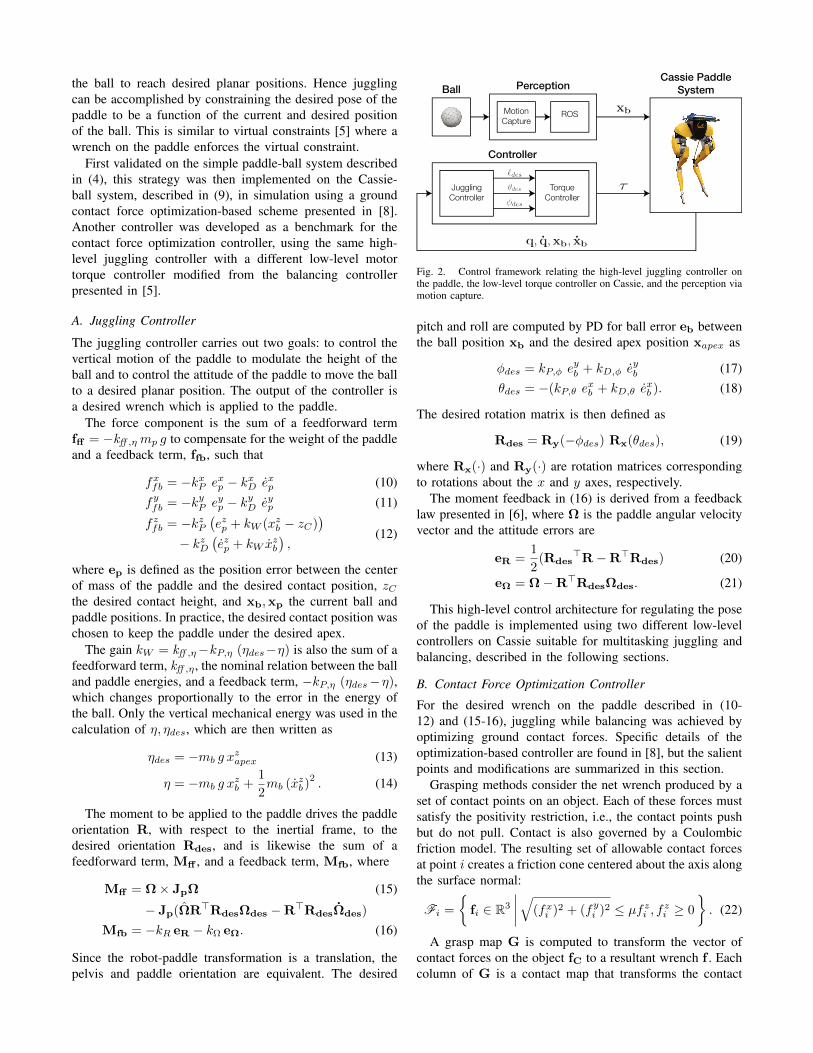
Fig. 2. Control framework relating the high-level juggling controller onthe paddle, the low-level torque controller on Cassie, and the perception viamotion capture.
pitch and roll are computed by PD for ball error eb betweenthe ball position xb and the desired apex position xapex as
φdes = kP,φ eyb + kD,φ e
yb (17)
θdes = −(kP,θ exb + kD,θ e
xb ). (18)
The desired rotation matrix is then defined as
Rdes = Ry(−φdes) Rx(θdes), (19)
where Rx(·) and Ry(·) are rotation matrices correspondingto rotations about the x and y axes, respectively.
The moment feedback in (16) is derived from a feedbacklaw presented in [6], where Ω is the paddle angular velocityvector and the attitude errors are
eR =1
2(Rdes
>R−R>Rdes) (20)
eΩ = Ω−R>RdesΩdes. (21)
This high-level control architecture for regulating the poseof the paddle is implemented using two different low-levelcontrollers on Cassie suitable for multitasking juggling andbalancing, described in the following sections.
B. Contact Force Optimization Controller
For the desired wrench on the paddle described in (10-12) and (15-16), juggling while balancing was achieved byoptimizing ground contact forces. Specific details of theoptimization-based controller are found in [8], but the salientpoints and modifications are summarized in this section.
Grasping methods consider the net wrench produced by aset of contact points on an object. Each of these forces mustsatisfy the positivity restriction, i.e., the contact points pushbut do not pull. Contact is also governed by a Coulombicfriction model. The resulting set of allowable contact forcesat point i creates a friction cone centered about the axis alongthe surface normal:
Fi =
fi ∈ R3
∣∣∣∣√(fxi )2 + (fyi )2 ≤ µfzi , fzi ≥ 0
. (22)
A grasp map G is computed to transform the vector ofcontact forces on the object fC to a resultant wrench f . Eachcolumn of G is a contact map that transforms the contact
force at a single point to a wrench in the object coordinateframe [8]. The total wrench on the object f is thus GfC.
The contact forces fC can be computed as the productof the pseudoinverse of the grasp map G† and the desiredwrench f . In general, this calculation does not guarantee theaforementioned constraints are satisfied, so a multi-objectiveoptimization problem is solved subject to these constraints.The first two terms (J1, J2) ensure forces and momentsgenerated on the paddle from the contact forces at the feetare close to the desired values computed by the high-levelcontroller, while the third (J3) minimizes the magnitude ofthe contact force, and are written as
J1 =∥∥[I3 03×3
](f −GfC)
∥∥2
2(23)
J2 =∥∥[03×3 I3
](f −GfC)
∥∥2
2(24)
J3 = fC>fC. (25)
For weights αi > 0, a single objective function is written as
J = α1J1 + α2J2 + α3J3. (26)
To prioritize balance, α1 α2 α3.Finally, contact wrenches fk at each contact point k
are constructed using these forces, which then allow thecomputation of the joint torques τ required to achieve thedesired contact forces as
τ = JC>fC (27)
C. PD Torque Controller
While the presented contact force optimization controllerworks in simulation, a simpler joint PD controller from [5]was also explored for this task. As in the optimization-based controller, the attitude of the paddle locates the ballin the plane while the vertical motion of the paddle is usedto regulate the energy of the ball. The desired attitude iscontrolled according to (17), (18).
In contrast to the optimization-based controller, the groundcontact forces are computed to modulate the length ` of thevirtual leg, defined from Cassie’s hip to its toe [5], to controlthe vertical height of the ball. For a desired contact heightzC as in (12) and vertical offset between the paddle and hiphoff , the desired leg length is
`des = −kW (xzb − zC)− hoff + zC . (28)
The motor torques can then be computed using the bal-ancing controller presented in [5] with the modification thatthe control law for both hip pitch motors, q3, is
q3 = −kP,3(φ− φdes)− kD,3φ. (29)
Balance was maintained by setting the virtual leg angle, i.e.,the angle between the vertical axis and the virtual leg, tozero. Thus, the center of mass of the robot was constrainedover the support polygon formed by the feet placed squarelyon the floor.
The stability of these controllers is detailed in the nextsection, followed by simulation and experimental results.
IV. STABILITY ANALYSIS
Stability of the controller described in the previous sectionwas determined by Poincare analysis of the Cassie-ballsystem. A Poincare section S was defined at the apex ofthe ball trajectory, i.e., xzb ≡ 0. The return map P : S → Sis defined by the continuous dynamics described in (9).
By choice of the Poincare section, the system passesthrough three phases: free-fall of the ball until impact withthe paddle, collision dynamics between the ball and thepaddle, and the ball leaving the surface of the paddle untilit reaches its apex. The complexity of modeling the systemdynamics of the robot and the effects of repeated interactionsbetween the robot and ball required simulating the Cassie-ball dynamics to identify a periodic orbit for a chosen xzapex.
Kinematic constraints on the system resulted in a lower-dimensional return map. Individual states were first perturbedand then the constraints were enforced before running theforward simulation. Of the 54 states, 40 describe Cassie,6 describe the motion of the ball, and 8 determine deforma-tion of the ground and paddle. Since a state on the Poincaresection must satisfy several constraints, such as the ball beingat its apex, feet being in contact with the ground, and thepaddle not being in contact with the ball, the number ofperturbable states was reduced to 17. Therefore, the Poincaremap P is reduced to
x[k + 1] = P (x[k]), (30)
where x ∈ R17 is the vector of perturbable states. This mapwas computed using the finite differences method about thechosen fixed point for both juggling controllers. The largesteigenvalue magnitudes for the optimization controller andfor the PD controller were 0.65 and 0.84, respectively. Thusboth controllers are locally exponentially stable.
V. SIMULATIONS
To evaluate these controllers, juggling was simulated on therobot-ball system. All simulation results presented here wereperformed in Matlab R2019b on a Lenovo Thinkpad X1Carbon laptop (Intel Core i7 CPU, 16 GB RAM).
For stationary juggling, only the position states of theball relative to the position of the paddle were varied.For an inertial frame set on the ground below the paddlecenter, the chosen ball initial conditions in meters were(0.05, 0.075, 1.3), (0.05, 0.075, 1.0), (0.05, 0.075, 1.6). Ofthe many initial conditions tested, these were deemed suffi-cient for verifying the robustness of the juggling controller.The desired apex was (0, 0, 1.3), so the proposed controllerswere tested for initial configurations when the ball wasdisplaced from the apex position along all three axes.
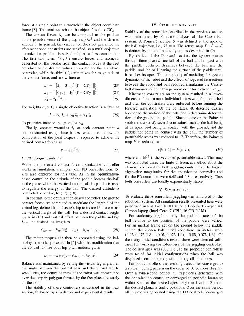
For both controllers, the resulting trajectories converged toa stable juggling pattern on the order of 10 bounces (Fig. 3).Over a four-second period, all trajectories generated withthe optimization controller converged to periodic bouncingwithin 8 cm of the desired apex height and within 2 cm ofthe desired planar x and y positions. Over the same period,all trajectories generated using the PD controller converged
0.8
1.0
1.2
1.4
1.6
-0.10
-0.05
0.00
0.05
0.10
0.0 0.5 1.0 1.5 2.0 2.5 3.0 3.5 4.0Time (s)
0.0 0.5 1.0 1.5 2.0 2.5 3.0 3.5 4.0Time (s)
Ball Planar Position Error
Ball Height
xe (z
0 = 1.3)
xe (z
0 = 1.6)
z (z0 = 1.3)
zapex, des
z (z0 = 1.6)
z (z0 = 1.0)
xe (z
0 = 1.0)
ye (z
0 = 1.3)
ye (z
0 = 1.6)
ye (z
0 = 1.0)
Simulation: Contact Force Optimization ControllerB
all P
ositi
on (m
)B
all P
ositi
on E
rror
(m)
Fig. 3. Simulation of the Cassie-ball system with the contact forceoptimization controller. The ball is dropped from three different initialheights (z0 = 1.0, 1.3, 1.6m). In all three cases, the desired apex height is1.3m, the ball apex settles to within 0.08m of the apex, and the planarball position converges to zero. The simulation with the PD controller showssimilar results. The subscript “e” denotes error.
Cassie-
Paddle-
Ball
System
Ball
Racket
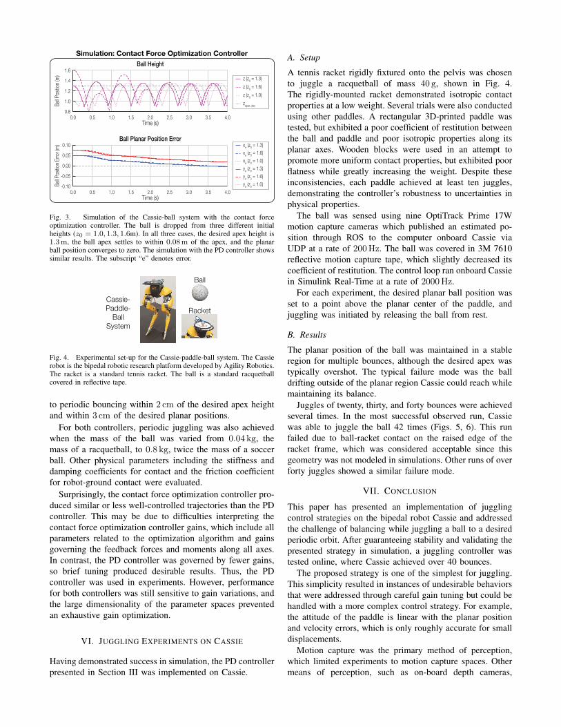
Fig. 4. Experimental set-up for the Cassie-paddle-ball system. The Cassierobot is the bipedal robotic research platform developed by Agility Robotics.The racket is a standard tennis racket. The ball is a standard racquetballcovered in reflective tape.
to periodic bouncing within 2 cm of the desired apex heightand within 3 cm of the desired planar positions.
For both controllers, periodic juggling was also achievedwhen the mass of the ball was varied from 0.04 kg, themass of a racquetball, to 0.8 kg, twice the mass of a soccerball. Other physical parameters including the stiffness anddamping coefficients for contact and the friction coefficientfor robot-ground contact were evaluated.
Surprisingly, the contact force optimization controller pro-duced similar or less well-controlled trajectories than the PDcontroller. This may be due to difficulties interpreting thecontact force optimization controller gains, which include allparameters related to the optimization algorithm and gainsgoverning the feedback forces and moments along all axes.In contrast, the PD controller was governed by fewer gains,so brief tuning produced desirable results. Thus, the PDcontroller was used in experiments. However, performancefor both controllers was still sensitive to gain variations, andthe large dimensionality of the parameter spaces preventedan exhaustive gain optimization.
VI. JUGGLING EXPERIMENTS ON CASSIE
Having demonstrated success in simulation, the PD controllerpresented in Section III was implemented on Cassie.
A. Setup
A tennis racket rigidly fixtured onto the pelvis was chosento juggle a racquetball of mass 40 g, shown in Fig. 4.The rigidly-mounted racket demonstrated isotropic contactproperties at a low weight. Several trials were also conductedusing other paddles. A rectangular 3D-printed paddle wastested, but exhibited a poor coefficient of restitution betweenthe ball and paddle and poor isotropic properties along itsplanar axes. Wooden blocks were used in an attempt topromote more uniform contact properties, but exhibited poorflatness while greatly increasing the weight. Despite theseinconsistencies, each paddle achieved at least ten juggles,demonstrating the controller’s robustness to uncertainties inphysical properties.
The ball was sensed using nine OptiTrack Prime 17Wmotion capture cameras which published an estimated po-sition through ROS to the computer onboard Cassie viaUDP at a rate of 200 Hz. The ball was covered in 3M 7610reflective motion capture tape, which slightly decreased itscoefficient of restitution. The control loop ran onboard Cassiein Simulink Real-Time at a rate of 2000 Hz.
For each experiment, the desired planar ball position wasset to a point above the planar center of the paddle, andjuggling was initiated by releasing the ball from rest.
B. Results
The planar position of the ball was maintained in a stableregion for multiple bounces, although the desired apex wastypically overshot. The typical failure mode was the balldrifting outside of the planar region Cassie could reach whilemaintaining its balance.
Juggles of twenty, thirty, and forty bounces were achievedseveral times. In the most successful observed run, Cassiewas able to juggle the ball 42 times (Figs. 5, 6). This runfailed due to ball-racket contact on the raised edge of theracket frame, which was considered acceptable since thisgeometry was not modeled in simulations. Other runs of overforty juggles showed a similar failure mode.
VII. CONCLUSION
This paper has presented an implementation of jugglingcontrol strategies on the bipedal robot Cassie and addressedthe challenge of balancing while juggling a ball to a desiredperiodic orbit. After guaranteeing stability and validating thepresented strategy in simulation, a juggling controller wastested online, where Cassie achieved over 40 bounces.
The proposed strategy is one of the simplest for juggling.This simplicity resulted in instances of undesirable behaviorsthat were addressed through careful gain tuning but could behandled with a more complex control strategy. For example,the attitude of the paddle is linear with the planar positionand velocity errors, which is only roughly accurate for smalldisplacements.
Motion capture was the primary method of perception,which limited experiments to motion capture spaces. Othermeans of perception, such as on-board depth cameras,
-0.10
-0.05
0.00
0.05
0.10
0.0 0.5 1.0 1.5 2.0 2.5 3.0 3.5 4.0Time (s)
0.0 0.5 1.0 1.5 2.0 2.5 3.0 3.5 4.0Time (s)
Ball Planar Position Error
Ball Height
z
zapex, des
xe
ye
Experiment: PD Controller (Transient behavior)
0.8
1.0
1.2
1.4
1.6
Bal
l Pos
ition
(m)
Bal
l Pos
ition
Err
or (m
)
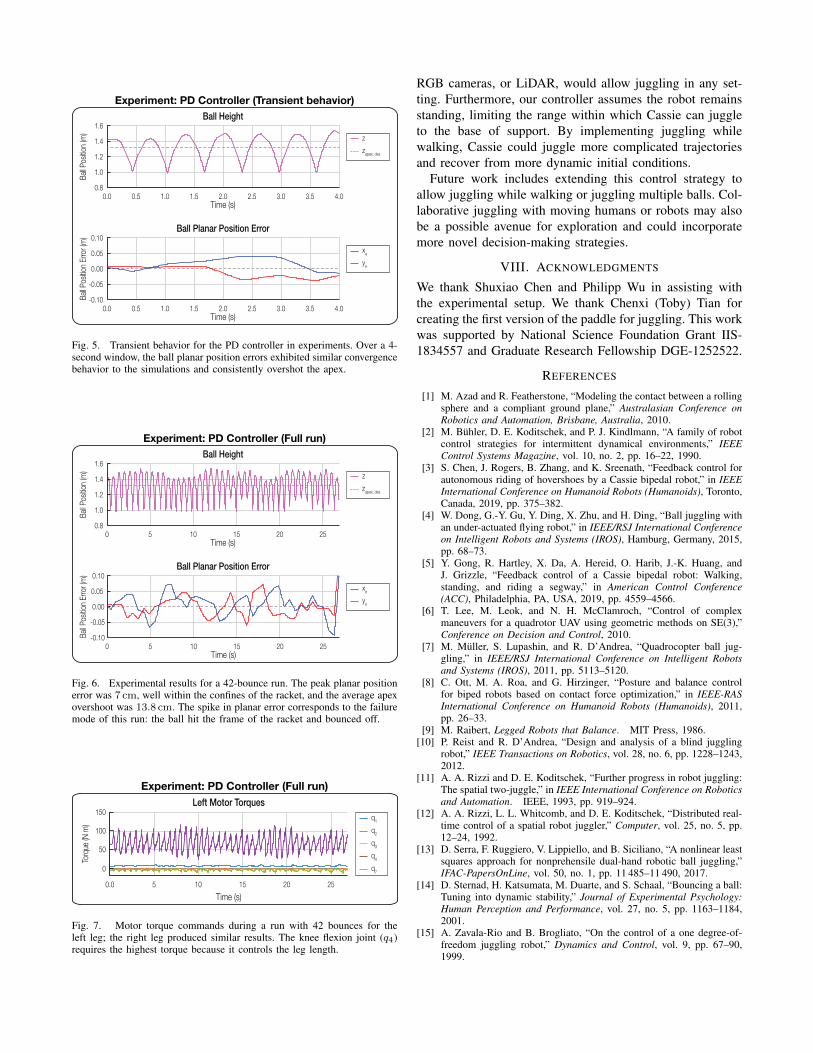
Fig. 5. Transient behavior for the PD controller in experiments. Over a 4-second window, the ball planar position errors exhibited similar convergencebehavior to the simulations and consistently overshot the apex.
-0.10
-0.05
0.00
0.05
0.10
0 5 10 15 20 25Time (s)
0 5 10 15 20 25Time (s)
Ball Planar Position Error
Ball Height
xe
ye
z
zapex, des
0.8
1.0
1.2
1.4
1.6
Experiment: PD Controller (Full run)
Bal
l Pos
ition
(m)
Bal
l Pos
ition
Err
or (m
)
Fig. 6. Experimental results for a 42-bounce run. The peak planar positionerror was 7 cm, well within the confines of the racket, and the average apexovershoot was 13.8 cm. The spike in planar error corresponds to the failuremode of this run: the ball hit the frame of the racket and bounced off.
0
50
100
150
0.0 5 10 15 20 25
Time (s)
Left Motor Torques
q1
q4
q2
q3
Experiment: PD Controller (Full run)
Torq
ue (N
m)
q7
Fig. 7. Motor torque commands during a run with 42 bounces for theleft leg; the right leg produced similar results. The knee flexion joint (q4)requires the highest torque because it controls the leg length.
RGB cameras, or LiDAR, would allow juggling in any set-ting. Furthermore, our controller assumes the robot remainsstanding, limiting the range within which Cassie can juggleto the base of support. By implementing juggling whilewalking, Cassie could juggle more complicated trajectoriesand recover from more dynamic initial conditions.
Future work includes extending this control strategy toallow juggling while walking or juggling multiple balls. Col-laborative juggling with moving humans or robots may alsobe a possible avenue for exploration and could incorporatemore novel decision-making strategies.
VIII. ACKNOWLEDGMENTS
We thank Shuxiao Chen and Philipp Wu in assisting withthe experimental setup. We thank Chenxi (Toby) Tian forcreating the first version of the paddle for juggling. This workwas supported by National Science Foundation Grant IIS-1834557 and Graduate Research Fellowship DGE-1252522.
REFERENCES
[1] M. Azad and R. Featherstone, “Modeling the contact between a rollingsphere and a compliant ground plane,” Australasian Conference onRobotics and Automation, Brisbane, Australia, 2010.
[2] M. Buhler, D. E. Koditschek, and P. J. Kindlmann, “A family of robotcontrol strategies for intermittent dynamical environments,” IEEEControl Systems Magazine, vol. 10, no. 2, pp. 16–22, 1990.
[3] S. Chen, J. Rogers, B. Zhang, and K. Sreenath, “Feedback control forautonomous riding of hovershoes by a Cassie bipedal robot,” in IEEEInternational Conference on Humanoid Robots (Humanoids), Toronto,Canada, 2019, pp. 375–382.
[4] W. Dong, G.-Y. Gu, Y. Ding, X. Zhu, and H. Ding, “Ball juggling withan under-actuated flying robot,” in IEEE/RSJ International Conferenceon Intelligent Robots and Systems (IROS), Hamburg, Germany, 2015,pp. 68–73.
[5] Y. Gong, R. Hartley, X. Da, A. Hereid, O. Harib, J.-K. Huang, andJ. Grizzle, “Feedback control of a Cassie bipedal robot: Walking,standing, and riding a segway,” in American Control Conference(ACC), Philadelphia, PA, USA, 2019, pp. 4559–4566.
[6] T. Lee, M. Leok, and N. H. McClamroch, “Control of complexmaneuvers for a quadrotor UAV using geometric methods on SE(3),”Conference on Decision and Control, 2010.
[7] M. Muller, S. Lupashin, and R. D’Andrea, “Quadrocopter ball jug-gling,” in IEEE/RSJ International Conference on Intelligent Robotsand Systems (IROS), 2011, pp. 5113–5120.
[8] C. Ott, M. A. Roa, and G. Hirzinger, “Posture and balance controlfor biped robots based on contact force optimization,” in IEEE-RASInternational Conference on Humanoid Robots (Humanoids), 2011,pp. 26–33.
[9] M. Raibert, Legged Robots that Balance. MIT Press, 1986.[10] P. Reist and R. D’Andrea, “Design and analysis of a blind juggling
robot,” IEEE Transactions on Robotics, vol. 28, no. 6, pp. 1228–1243,2012.
[11] A. A. Rizzi and D. E. Koditschek, “Further progress in robot juggling:The spatial two-juggle,” in IEEE International Conference on Roboticsand Automation. IEEE, 1993, pp. 919–924.
[12] A. A. Rizzi, L. L. Whitcomb, and D. E. Koditschek, “Distributed real-time control of a spatial robot juggler,” Computer, vol. 25, no. 5, pp.12–24, 1992.
[13] D. Serra, F. Ruggiero, V. Lippiello, and B. Siciliano, “A nonlinear leastsquares approach for nonprehensile dual-hand robotic ball juggling,”IFAC-PapersOnLine, vol. 50, no. 1, pp. 11 485–11 490, 2017.
[14] D. Sternad, H. Katsumata, M. Duarte, and S. Schaal, “Bouncing a ball:Tuning into dynamic stability,” Journal of Experimental Psychology:Human Perception and Performance, vol. 27, no. 5, pp. 1163–1184,2001.
[15] A. Zavala-Rio and B. Brogliato, “On the control of a one degree-of-freedom juggling robot,” Dynamics and Control, vol. 9, pp. 67–90,1999.
Recommended