100 | Visit www.dunkermotoren.com for further product information/ Besuchen Sie www.dunkermotoren.de für weitere Produktinformationen Visit www.dunkermotoren.com for further product information/ Besuchen Sie www.dunkermotoren.de für weitere Produktinformationen | 101
» With integrated speed controller for 4-quadrant drive » As standard, the target speed can be set
using a 0 ... +10 V (optional -10 V ... +10 V) analog voltage input » The motor is supplied as standard with a
15-pin connector. » MR encoder for particuarly high control accuracy available on request
» Comes with easy to use PC user interface for parameterization
» Mit integriertem Speedcontroller für 4-Quadrantenbetrieb » Die Drehzahlsollwertvorgabe erfolgt standard-
mäßig über einen Analogspannungseingang 0 ... +10 V (optional -10 V ... +10 V) » Der Motor ist standardmäßig mit einem 15-
poligen Anschlussstecker versehen. » Optional MR Geber für besonders hohe Regelgüte erhältlich
» Mit komfortable PC-Bedienoberfläche zur Parametrierung
Data/ Technische Daten BG 65Sx25 SI BG 65Sx50 SINominal voltage/Nennspannung VDC 24 40 24 40
Nominal current/Nennstrom A*) 6 3.6 8.3 5.4
Nominal torque/Nennmoment Ncm*) 38 38.1 48 51
Nominal speed/Nenndrehzahl rpm*) 2700 2700 3140 3210
Friction torque/Reibungsmoment Ncm*) 4.3 4.5 7 8.5
Stall torque/Anhaltemoment Ncm**) 77 78 152 152
No load speed/Leerlaufdrehzahl rpm*) 4080 4240 4300 4400
Nominal output power/Dauerabgabeleistung W**) 107 108 158 171
Maximum output power/Maximale Abgabeleistung W 154 169 302 327
Torque constant/Drehmomentkonstante Ncm A-1* * *) 7.8 12.5 7.4 12.3
Peak current/Zulässiger Spitzenstrom A**) 16 (75 sec.) 10 (77 sec.) 32 (78 sec.) 20 (86 sec.)
Rotor inertia/Rotor Trägheitsmoment gcm2 70 70 129 129
Weight of motor/Motorgewicht kg 1.2 1.2 1.65 1.65
Recommended speed control range/Empfohlener Drehzahlregelbereich rpm 70 ... Rated speed/ Nenndrehzahl
*) ∆ϑw = 100 K; **) JR = 20°C ***) at nominal point/ im Nennpunkt
BG 65S SI | cont. 171 W, peak 327 W
Modular System/ Modulares Baukastensystem
» Planetary gearbox/ Planetengetriebe PLG 60, Page/ Seite 194 PLG 63, Page/ Seite 194 PLG 75, Page/ Seite 198 PLG 80 LB » Worm gearbox/ Schneckengetriebe SG 120, Page/ Seite 208 » Spirotec gearbox/ Spirotecgetriebe STG 65, Page/ Seite 204
» Brakes & Encoder/ Bremsen & Anbauten E 90 R, Page/ Seite 212 E 100, Page/ Seite 212 E 300, Page/ Seite 212
» Accessories/ Zubehör Cover/ Verschlussdeckel, Connector cable for BG 45 SI | BG 65 S, 15-pin/ Anschlussleitung mit Dose für BG 45 SI | BG 65 S, 15-polig, Starter Kit BGxx SI, Page/ Seite 220
SG 120
E 90 R E 100 E 300
BG 65S SI
PLG 60 PLG 63 PLG 75PLG 80 LB
» All attachments also fully in the motor housing availbale./ Alle Anbauten auch vollständig im Motorgehäuse erhältlich.
Preference/ Vorzugsreihe On request/ auf Anfrage
STG 65
L
49
BG 65 S SI, 110 - 170 W
L
A
Ø 32 -0.04
(4x M5 (7 tief/deep)) Ø 45 ± 0.1 +1
(4x M5 (7 tief/deep)) Ø 40 ± 0.1 +1
B
Ø 32 -0.04
(4x M5 (7 tief/deep)) Ø 45 ± 0.1 +1
(4x M5 (7 tief/deep)) Ø 40 ± 0.1 +1
Connector/ Stecker M16, 15-pin, Fa. Hummel, H16
32±
1
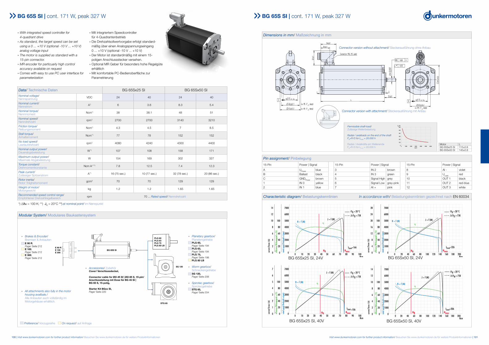
Dimensions in mm / Maßzeichnung in mm
Characteristic diagram / Belastungskennlinien In accordance with EN 60034 Belastungskennlinien gezeichnet nach EN 60034
Motor LBG 65Sx25SI 115±0.8BG 65Sx50SI 140±0.8
Pin assignment / Pinbelegung15-Pin Power / Signal 15-Pin Power / Signal 15-Pin Power / Signal
A UPower 3 IN2 8 AI-
B Ballast 4 IN3 9 ULogic
C GNDPower 5 CAN H 10 OUT1
1 IN0 6 CAN L 11 OUT2
2 IN1 7 AI+ 12 OUT3
BG 65Sx50 SI, 24 V
BG 65Sx25 SI, 40 V BG 65Sx50 SI, 40 V
BG 65Sx25 SI, 24 V 0 10 20 30 40 50 60 70 80 90 100
Ncm
7000
6000
5000
4000
3000
2000
1000
0
100
80
60
40
20
0
14
12
10
8
6
4
2
0 rated
spee
d/Dr
ehza
hl n
(rpm)
effic
iency
/Wirk
ungs
grad
η (%
)
curre
nt/S
trom
I(A)
MN
η
η
η
0 10 20 30 40 50 60 70 80 90 100Ncm
7000
6000
5000
4000
3000
2000
1000
0
100
80
60
40
20
0
7
6
5
4
3
2
1
0 rated
spee
d/Dr
ehza
hl n
(rpm)
effic
iency
/Wirk
ungs
grad
η (%
)
curre
nt/S
trom
I(A)
MN
0 20 40 60 80 100 120 140 160 180 200Ncm
7000
6000
5000
4000
3000
2000
1000
0
100
80
60
40
20
0
28
24
20
16
12
8
4
0 rated
spee
d/Dr
ehza
hl n
(rpm)
effic
iency
/Wirk
ungs
grad
η (%
)
curre
nt/S
trom
I(A)
MN MmaxMmax
Mmax
ϑR = 20°C
ΔϑEl = 75K
ϑR = 20°C
ΔϑEl = 75K
ϑR = 20°C
ΔϑEl = 75K
ILimit=10A
ILimit=16A ILimit=32A
J = f (M)J = f (M)
J = f (M)
N = f (M)
N = f (M) N = f (M)
0 20 40 60 80 100 120 140 160 180 200Ncm
7000
6000
5000
4000
3000
2000
1000
0
100
80
60
40
20
0
14
12
10
8
6
4
2
0 rated
spee
d/Dr
ehza
hl n
(rpm)
effic
iency
/Wirk
ungs
grad
η (%
)
curre
nt/S
trom
I (A)
MN
N = f (M)
J = f (M)
η
W
Mmax
ϑR = 20°C
Δϑ = 75K
ILimit=20A
Pin assignment/ Pinbelegung
15-Pin Power | Signal 15-Pin Power | Signal 15-Pin Power | Signal
A UPower blue 3 IN 2 brown 8 AI - violet
B Ballast black 4 IN 3 green 9 ULogic red
C GNDPower brown 5 Signal High grey 10 OUT 1 black
1 IN 0 yellow 6 Signal Low grey-pink 11 OUT 2 red-blue
2 IN 1 blue 7 AI + pink 12 OUT 3 white
Dimensions in mm/ Maßzeichnung in mm
Motor LBG 65Sx25 SI 115±0.8BG 65Sx50 SI 140±0.8
49
BG 65 S SI, 110 - 170 W
L
A
Ø 32 -0.04
(4x M5 (7 tief/deep)) Ø 45 ± 0.1 +1
(4x M5 (7 tief/deep)) Ø 40 ± 0.1 +1
B
Ø 32 -0.04
(4x M5 (7 tief/deep)) Ø 45 ± 0.1 +1
(4x M5 (7 tief/deep)) Ø 40 ± 0.1 +1
Connector/ Stecker M16, 15-pin, Fa. Hummel, H16
32±
1
Dimensions in mm / Maßzeichnung in mm
Characteristic diagram / Belastungskennlinien In accordance with EN 60034 Belastungskennlinien gezeichnet nach EN 60034
Motor LBG 65Sx25SI 115±0.8BG 65Sx50SI 140±0.8
Pin assignment / Pinbelegung15-Pin Power / Signal 15-Pin Power / Signal 15-Pin Power / Signal
A UPower 3 IN2 8 AI-
B Ballast 4 IN3 9 ULogic
C GNDPower 5 CAN H 10 OUT1
1 IN0 6 CAN L 11 OUT2
2 IN1 7 AI+ 12 OUT3
BG 65Sx50 SI, 24 V
BG 65Sx25 SI, 40 V BG 65Sx50 SI, 40 V
BG 65Sx25 SI, 24 V 0 10 20 30 40 50 60 70 80 90 100
Ncm
7000
6000
5000
4000
3000
2000
1000
0
100
80
60
40
20
0
14
12
10
8
6
4
2
0 rated
spee
d/Dr
ehza
hl n
(rpm)
effic
iency
/Wirk
ungs
grad
η (%
)
curre
nt/S
trom
I(A)
MN
η
η
η
0 10 20 30 40 50 60 70 80 90 100Ncm
7000
6000
5000
4000
3000
2000
1000
0
100
80
60
40
20
0
7
6
5
4
3
2
1
0 rated
spee
d/Dr
ehza
hl n
(rpm)
effic
iency
/Wirk
ungs
grad
η (%
)
curre
nt/S
trom
I(A)
MN
0 20 40 60 80 100 120 140 160 180 200Ncm
7000
6000
5000
4000
3000
2000
1000
0
100
80
60
40
20
0
28
24
20
16
12
8
4
0 rated
spee
d/Dr
ehza
hl n
(rpm)
effic
iency
/Wirk
ungs
grad
η (%
)
curre
nt/S
trom
I(A)
MN MmaxMmax
Mmax
ϑR = 20°C
ΔϑEl = 75K
ϑR = 20°C
ΔϑEl = 75K
ϑR = 20°C
ΔϑEl = 75K
ILimit=10A
ILimit=16A ILimit=32A
J = f (M)J = f (M)
J = f (M)
N = f (M)
N = f (M) N = f (M)
0 20 40 60 80 100 120 140 160 180 200Ncm
7000
6000
5000
4000
3000
2000
1000
0
100
80
60
40
20
0
14
12
10
8
6
4
2
0 rated
spee
d/Dr
ehza
hl n
(rpm)
effic
iency
/Wirk
ungs
grad
η (%
)
curre
nt/S
trom
I (A)
MN
N = f (M)
J = f (M)
η
W
Mmax
ϑR = 20°C
Δϑ = 75K
ILimit=20A
BG 65S SI | cont. 171 W, peak 327 W
BG 65Sx50 SI, 24VBG 65Sx25 SI, 24V
BG 65Sx25 SI, 40V BG 65Sx50 SI, 40V
Connector version without attachment/ Steckerausführung ohne Anbau
Connector version with attachment/ Steckerausführung mit Anbau
Characteristic diagram/ Belastungskennlinien In accordance with/ Belastungskennlinien gezeichnet nach EN 60034
0 1000 2000 3000 4000 5000 6000[rpm]
FR [N]600
500
400
300
200
100
0
Permissible shaft-load/ Zulässige Wellenbelastung
Radial-/ axialloads on the end of the shaft FA=Fr/3 for Lh10 = 20.000 h
Radial-/ Axialkräfte am Wellenende FA=Fr/3 für Lh10 = 20.000 h
Recommended