Building EnvelopeThermal Bridging Guide
V E R S I O N 1.2
2018

BUILDING ENVELOPE THERMAL BRIDGING GUIDE
ACKNOWLEDGEMENTS This Building Envelope Thermal Bridging Guide was prepared by Morrison Hershfield Ltd. in collaboration with many stakeholders and industry partners. We would like to thank the organizations and individuals that made this undertaking possible.
The Project Co-Sponsors
BC Hydro Power Smart BC Housing Canadian Wood Council
Fortis BC FPInnovations
Industry Advisors
The following organizations were included as industry advisors for the completion of the guide.
Architectural Institute of British Columbia (AIBC) Building and Safety Standards Branch, BC City of North Vancouver Engineers and Geoscientists British Columbia (EGBC) Fenestration Association of BC (FEN-BC) Urban Development Institute (UDI)
We wish to also gratefully thank the following individuals for their active participation in steering this guide to completion.
Bojan Andjelkovic, BC Hydro Curt Hepting, EnerSys Analytics Inc Dan Bradly, FortisBC Denisa Ionescu, BC Housing Gordon Monk, BC Hydro Jieying Wang, FPInnovations Jim Kobialko, FortisBC
Jonathan Meads, Concert Properties Oscar Ceron, BC Hydro Peggy Lepper, Canadian Wood Council Remi Charron, BC Housing Robert Jonkman, Canadian Wood Council Tim Ryce, City of North Vancouver
Industry Partners
We wish to extend a special thanks to the manufacturers and industry partners that helped extend the scope of the thermal performance catalogue. Thanks to the support and contributions of the following industry partners: Armadillo NV, Canadian Sheet Steel Building Institute (CSSBI), Dow Corning Corporation, EIFS Council of Canada, Hohmann & Barnard, JK Thermal, Owens Corning Canada, Schöck Bauteile GmbH, Tnemec and the manufacturers of proprietary cladding attachments (American Fiber Cement Corporation, Cascadia Windows, CL Talon, ECO Cladding, Engineered Assemblies, ETG, Knight Wall, Mayne Coatings, Northern Facades, Nvelope). These industry partners provided the funding to evaluate many variations of solutions that mitigate the impact of thermal bridging.
Preparation of the Guide
We acknowledge the team at Morrison Hershfield Ltd. for their dedication, insight, and collaborated effort in preparing this guide. MH’s team included the following individuals:
Alex Blue, Christian Cianfrone, David Fookes, Eileen Holt, Fabio Almeida, Ivan Lee, Jameson Vong, Julien Schwartz, Katie Hay, Mark Lawton, Matthew Doiron, Michael van der Laan, Neil Norris, Nick Adamson, Patrick Roppel, Radu Postole and Ruth McClung.
Finally, we acknowledge the contribution of Heatherbrae Builders in providing the construction cost estimates that were utilized in the costs benefit analysis.

BUILDING ENVELOPE THERMAL BRIDGING GUIDE
What’s New in Edition 1.2
The most significant change to the BETB Guide is that many more details and assemblies were added to the thermal performance catalogue. A summary of the additional details follows.
Steel-framed walls: many additional proprietary cladding attachments, thermally broken interface details, and several details for mitigating thermal bridges at interface details (window interface, intermediate floor).
Concrete walls: thermally broken precast concrete interface details (panel joints, window transition, and parapet), insulated floor column penetration, and several details for mitigating thermal bridges at interface details (window interface).
Wood-framed walls: brick veneer interface details (shelf angle), several details for mitigating thermal bridges at interface details (window interface).
BUILDING ENVELOPE THERMAL BRIDGING GUIDE
DISCLAIMER
This publication is provided to inform the practice of applying the Building Envelope Thermal
Analysis (BETA) methodology for determining the effective thermal performance of building
envelope assembly and interface details, as well as to guide BETA’s application in overall building
design. The greatest care has been taken to confirm the accuracy of the information contained
herein. However, the authors, co-sponsors, industry advisors, industry partners and other
contributors assume no liability for any damage, injury, loss or expense that may be incurred or
suffered as result of the use of this publication, building envelope design methodology or energy
modelling practices. The views expressed herein do not necessarily represent those of any
individual contributor. Nothing in this publication is an endorsement of any proprietary building
envelope system or particular assembly product.
In addition to using this publication, readers are encouraged to consult applicable up-to-date
technical publications on building envelope science, practices and products. Retain consultants
with appropriate architectural and/ or engineering qualifications and speak with appropriate
municipal and other authorities with respect to issues of envelope design, assembly fabrication
and construction practices. It is also advisable to seek specific information on the use of
envelope-related products and consult the instructions of envelope assembly manufacturers.
Always review and comply with the specific requirements of the applicable building codes for any
construction project.
Copyright © 2018, all rights reserved. BC Hydro Power Smart 333 Dunsmuir Street Vancouver, BC V6B 5R3
BUILDING ENVELOPE THERMAL BRIDGING GUIDE
TABLE OF CONTENTS
1. OVERVIEW ........................................................................................................... I
2. GLOSSARY OF TERMS ........................................................................................ 4
3. METHODOLOGY FOR DETERMINING THERMAL PERFORMANCE OF
BUILDING ENVELOPE ASSEMBLIES ..................................................................... 8
3.1 DETERMINING THERMAL PERFORMANCE OF CLEAR FIELD ASSEMBLIES ................ 9
3.2 DETERMINING THERMAL PERFORMANCE OF INTERFACE DETAILS – AREA
WEIGHTED APPROACH ................................................................................. 10
3.3 DETERMINING THERMAL PERFORMANCE OF INTERFACE DETAILS UTILIZING
LINEAR TRANSMITTANCES .............................................................................. 10
3.4 DETERMINING OVERALL THERMAL PERFORMANCE .......................................... 12
3.4.1 Finding Length and Area Takeoffs ...................................................... 13
4. SUMMARY OF THE THERMAL PERFORMANCE CATALOGUE ........................... 18
4.1 CATALOGUE BREAKDOWN ........................................................................... 18
4.2 THERMAL PERFORMANCE CATEGORIES .......................................................... 19
4.3 OTHER SOURCES OF INFORMATION ................................................................ 22
5. EXAMPLE UTILIZATION OF THE CATALOGUE ................................................... 24
6. INPUTTING THERMAL VALUES INTO ENERGY MODELS .................................... 30
7. REFERENCES ..................................................................................................... 32
APPENDIX A: CATALOGUE MATERIAL DATA SHEETS
APPENDIX B: CATALOGUE THERMAL DATA SHEETS
BUILDING ENVELOPE THERMAL BRIDGING GUIDE
1
1. OVERVIEW
In British Columbia, a large percentage of electricity and natural gas is consumed in commercial, institutional, and residential buildings. Improved energy conservation in buildings has long been recognized as an important approach to reduce energy consumption and greenhouse gas emissions in BC. Government and utilities have a mandate to encourage energy conversation in buildings and BC jurisdictions have been adopting increasingly more stringent building energy efficiency standards. Space conditioning, primarily heating, is one of the largest components of energy use in commercial, institutional, and residential buildings in BC. Building envelope thermal performance is a critical consideration for reducing space heating loads and will be an increasingly important factor as authorities strive for lower energy consumption in buildings.
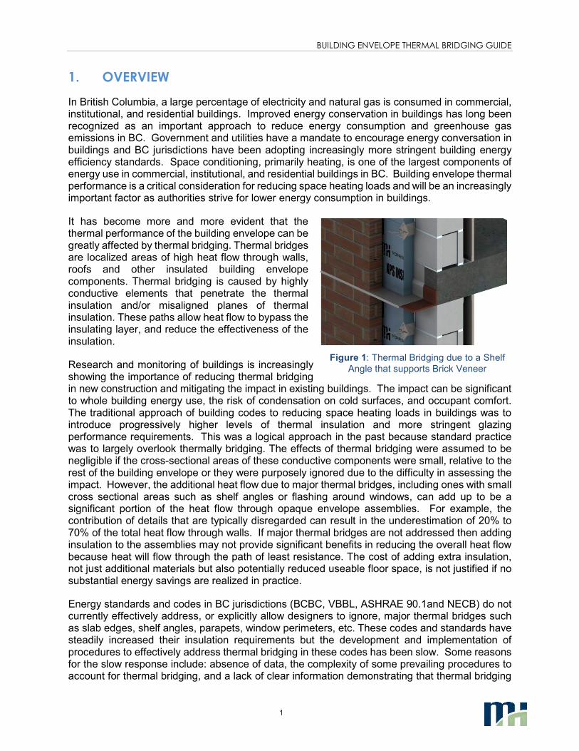
It has become more and more evident that the thermal performance of the building envelope can be greatly affected by thermal bridging. Thermal bridges are localized areas of high heat flow through walls, roofs and other insulated building envelope components. Thermal bridging is caused by highly conductive elements that penetrate the thermal insulation and/or misaligned planes of thermal insulation. These paths allow heat flow to bypass the insulating layer, and reduce the effectiveness of the insulation.
Research and monitoring of buildings is increasingly showing the importance of reducing thermal bridging in new construction and mitigating the impact in existing buildings. The impact can be significant to whole building energy use, the risk of condensation on cold surfaces, and occupant comfort. The traditional approach of building codes to reducing space heating loads in buildings was to introduce progressively higher levels of thermal insulation and more stringent glazing performance requirements. This was a logical approach in the past because standard practice was to largely overlook thermally bridging. The effects of thermal bridging were assumed to be negligible if the cross-sectional areas of these conductive components were small, relative to the rest of the building envelope or they were purposely ignored due to the difficulty in assessing the impact. However, the additional heat flow due to major thermal bridges, including ones with small cross sectional areas such as shelf angles or flashing around windows, can add up to be a significant portion of the heat flow through opaque envelope assemblies. For example, the contribution of details that are typically disregarded can result in the underestimation of 20% to 70% of the total heat flow through walls. If major thermal bridges are not addressed then adding insulation to the assemblies may not provide significant benefits in reducing the overall heat flow because heat will flow through the path of least resistance. The cost of adding extra insulation, not just additional materials but also potentially reduced useable floor space, is not justified if no substantial energy savings are realized in practice.
Energy standards and codes in BC jurisdictions (BCBC, VBBL, ASHRAE 90.1and NECB) do not currently effectively address, or explicitly allow designers to ignore, major thermal bridges such as slab edges, shelf angles, parapets, window perimeters, etc. These codes and standards have steadily increased their insulation requirements but the development and implementation of procedures to effectively address thermal bridging in these codes has been slow. Some reasons for the slow response include: absence of data, the complexity of some prevailing procedures to account for thermal bridging, and a lack of clear information demonstrating that thermal bridging
Figure 1: Thermal Bridging due to a Shelf
Angle that supports Brick Veneer
BUILDING ENVELOPE THERMAL BRIDGING GUIDE
2
needs to be more thoroughly addressed. Moreover, reaching agreement for how to implement significant changes to codes and standards can be challenging for committees comprised of a wide range of interests, backgrounds and perspectives.
With this context in mind, the original guide explored how the building industry in BC can realistically meet the challenges of reducing energy use in buildings, in part by effectively accounting for the impact of thermal bridging. The goal of the co-sponsors of the BETB Guide is to help transform the BC construction sector to realize more energy efficient buildings. To help meet this goal, the primary objective of the BETB Guide was to address the obstacles currently confronting our industry, with regard to thermal bridging, by:
1. Providing a catalogue of the thermal performance of common envelope assemblies and interface details directly relevant to construction in BC.
2. Providing information that makes it easier for industry to comprehensively consider thermal bridging in building codes and bylaws, design, and whole building energy simulations.
3. Examining the costs associated with improving the thermal performance of opaque building envelope assemblies and interface details, and forecasting the energy impact for several building types and BC climates.
4. Evaluating the cost effectiveness of improving the building envelope through more thermally efficient assemblies, interface details, and increasing insulation levels.
Scope
The evaluation of energy use in buildings requires a reasonably accurate assessment of heat transfer through the building envelope which includes the heat passing through thermal bridges at interfaces and penetrations. A previous study, ASHRAE 1365-RP “Thermal Performance of Building Envelope Details for Mid- and High-Rise Buildings” (Morrison Hershfield Limited, 2011), put forward procedures and data that allowed practitioners to evaluate the impact of thermal bridging in a comprehensive and straightforward method. This started a market transformation to better evaluate building performance and design for energy conservation. 1365-RP, which contained 40 common building envelope assemblies for mid- and high-rise construction, was a good start in creating a building envelope thermal performance catalogue. However, that report only scratched the surface, particularly in identifying how to effectively mitigate thermal bridging in design. The intent of the BETB Guide is to expand on the previous work and become a living document, by continuing to show where opportunities exist to improve building envelope thermal performance.
It is important to recognize that this guide is deliberately narrow in scope. The focus is on the thermal performance of the opaque building envelope. A wide range of opaque assemblies were evaluated in preparation of this guide; however, the thermal performance of the opaque building envelope is only one of many considerations for reducing energy use in buildings and the relative impact changes as other building energy uses are reduced. Refer to the original version of the BETB Guide released in 2014 for sections related to energy savings and cost benefit analysis (Part 2) and market transformation (Part 3: Significance, Insights and Next Steps).
Audience
The target audiences for this guide are broad: committees for energy standards, policy and government, utilities, architects, mechanical designers, building envelope consultants, energy

BUILDING ENVELOPE THERMAL BRIDGING GUIDE
3
modellers, developers and contractors, manufacturers and trade organizations. From a high level awareness perspective, the information provided is relevant to all the target audiences. All stakeholders should be aware of the information, understand the benefits of the methodology, and understand in concept how the methodology and data can be used in practice. Only designers, architects, engineers, energy modelers, and building envelope consultants really need to delve deep into the methodology and fully understand how to utilize the thermal performance data in practice.
BUILDING ENVELOPE THERMAL BRIDGING GUIDE
4
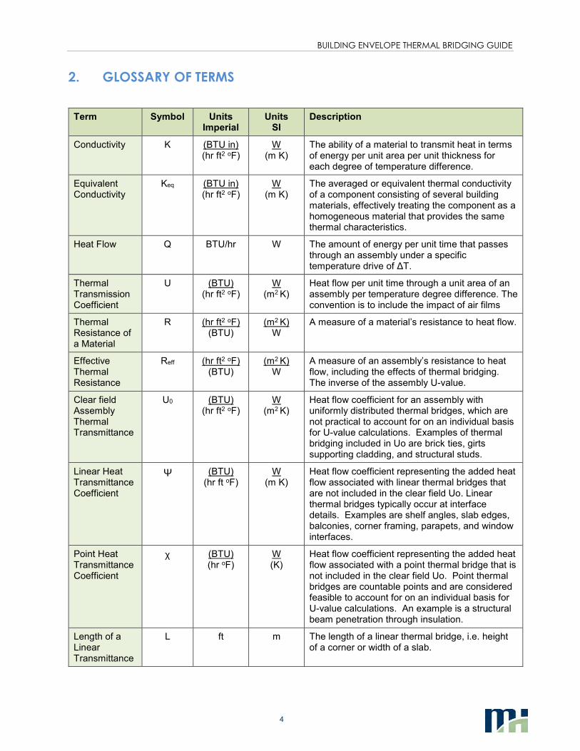
2. GLOSSARY OF TERMS
Term Symbol Units Imperial
Units SI
Description
Conductivity K (BTU in) (hr ft2 oF)
W (m K)
The ability of a material to transmit heat in terms of energy per unit area per unit thickness for each degree of temperature difference.
Equivalent Conductivity
Keq (BTU in) (hr ft2 oF)
W (m K)
The averaged or equivalent thermal conductivity of a component consisting of several building materials, effectively treating the component as a homogeneous material that provides the same thermal characteristics.
Heat Flow Q BTU/hr W The amount of energy per unit time that passes through an assembly under a specific temperature drive of ∆T.
Thermal Transmission Coefficient
U (BTU) (hr ft2 oF)
W (m2 K)
Heat flow per unit time through a unit area of an assembly per temperature degree difference. The convention is to include the impact of air films
Thermal Resistance of a Material
R (hr ft2 oF) (BTU)
(m2 K) W
A measure of a material’s resistance to heat flow.
Effective Thermal Resistance
Reff (hr ft2 oF) (BTU)
(m2 K) W
A measure of an assembly’s resistance to heat flow, including the effects of thermal bridging. The inverse of the assembly U-value.
Clear field Assembly Thermal Transmittance
U0 (BTU) (hr ft2 oF)
W (m2 K)
Heat flow coefficient for an assembly with uniformly distributed thermal bridges, which are not practical to account for on an individual basis for U-value calculations. Examples of thermal bridging included in Uo are brick ties, girts supporting cladding, and structural studs.
Linear Heat Transmittance Coefficient
Ψ (BTU) (hr ft oF)
W (m K)
Heat flow coefficient representing the added heat flow associated with linear thermal bridges that are not included in the clear field Uo. Linear thermal bridges typically occur at interface details. Examples are shelf angles, slab edges, balconies, corner framing, parapets, and window interfaces.
Point Heat Transmittance Coefficient
χ (BTU) (hr oF)
W (K)
Heat flow coefficient representing the added heat flow associated with a point thermal bridge that is not included in the clear field Uo. Point thermal bridges are countable points and are considered feasible to account for on an individual basis for U-value calculations. An example is a structural beam penetration through insulation.
Length of a Linear Transmittance
L ft m The length of a linear thermal bridge, i.e. height of a corner or width of a slab.
BUILDING ENVELOPE THERMAL BRIDGING GUIDE
5
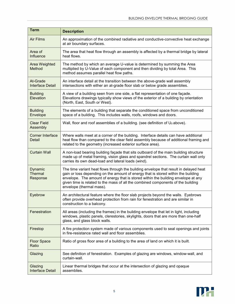
Term Description
Air Films An approximation of the combined radiative and conductive-convective heat exchange at air boundary surfaces.
Area of Influence
The area that heat flow through an assembly is affected by a thermal bridge by lateral heat flows.
Area Weighted Method
The method by which an average U-value is determined by summing the Area multiplied by U-Value of each component and then dividing by total Area. This method assumes parallel heat flow paths.
At-Grade Interface Detail
An interface detail at the transition between the above-grade wall assembly intersections with either an at-grade floor slab or below grade assemblies.
Building Elevation
A view of a building seen from one side, a flat representation of one façade. Elevations drawings typically show views of the exterior of a building by orientation (North, East, South or West).
Building Envelope
The elements of a building that separate the conditioned space from unconditioned space of a building. This includes walls, roofs, windows and doors.
Clear Field Assembly
Wall, floor and roof assemblies of a building. (see definition of U0 above).
Corner Interface Detail
Where walls meet at a corner of the building. Interface details can have additional heat flow than compared to the clear field assembly because of additional framing and related to the geometry (increased exterior surface area).
Curtain Wall A non-load bearing building façade that sits outboard of the main building structure made up of metal framing, vision glass and spandrel sections. The curtain wall only carries its own dead-load and lateral loads (wind).
Dynamic Thermal Response
The time variant heat flows through the building envelope that result in delayed heat gain or loss depending on the amount of energy that is stored within the building envelope. The amount of energy that is stored within the building envelope at any given time is related to the mass of all the combined components of the building envelope (thermal mass).
Eyebrow An architectural feature where the floor slab projects beyond the walls. Eyebrows often provide overhead protection from rain for fenestration and are similar in construction to a balcony.
Fenestration All areas (including the frames) in the building envelope that let in light, including windows, plastic panels, clerestories, skylights, doors that are more than one-half glass, and glass block walls.
Firestop A fire protection system made of various components used to seal openings and joints in fire-resistance rated wall and floor assemblies.
Floor Space Ratio
Ratio of gross floor area of a building to the area of land on which it is built.
Glazing See definition of fenestration. Examples of glazing are windows, window-wall, and curtain-wall.
Glazing Interface Detail
Linear thermal bridges that occur at the intersection of glazing and opaque assemblies.
BUILDING ENVELOPE THERMAL BRIDGING GUIDE
6
Term Description
Insulating Glass Unit (IGU)
Double or triple glass planes separated by air or other gas filled space. The space between the panes is glass is created by a physical spacer that is also adhered to the glass. Sealant is provided at the perimeter of the unit as a gas and moisture barrier.
Interface Details Thermal bridging related to the details at the intersection of building envelope assemblies and/or structural components. Interface details interrupt the uniformity of a clear field assembly and the additional heat loss associated with interface details is accounted for by linear and point thermal transmittances.
Lateral Heat Flow
Heat flow in multiple directions through an assembly as a result of conductive components bypassing the thermal insulation in multiple dimensions.
Linear Thermal Bridge
An interface detail that can be defined by a linear length along a plane of the building envelope.
MURB Multi-unit residential building.
Opaque Assembly
All areas in the building envelope, except fenestration and building services openings such as vents and grilles.
Parallel Path The assumption that the heat flow paths through an assembly are perpendicular to the plane of the assembly and there is no lateral heat flow.
Parapet An interface detail that joins the walls to the roof.
Point Thermal Bridge
Points of heat loss that are considered feasible to account for on an individual basis for U-value calculations. An example is a structural beam penetrations through insulation.
Poured-in-Place Concrete Wall
An architectural exposed concrete wall that is formed at the location of installation and is part of the building structural support.
Precast Concrete Wall
An architectural concrete cladding that is formed off site and shipped to the location of installation.
Plane of Heat Transfer
The theoretical projected area between the interior and exterior environment where the net heat flow through the building envelope is calculated.
Plug Loads Any system that draws electrical power through the building, but is not explicitly used to operate the building. This includes appliances, computers and other items that are dependent on the occupants use.
Set point Temperature
The desired operating temperature that a heating system works to maintain, ie: the interior space temperature set by a thermostat.
Shelf Angle A structural support that transfers the dead load of brick veneer to the building structure at the floor slab.
Floor Slab A concrete floor that partially or fully penetrates the building envelope at the exterior.
Slab Bypass A portion of window-wall that covers the floor slab edge to give the appearance of uninterrupted glazing across the entire façade of a building.
Spandrel Section
An opaque section of curtain wall or window wall with insulation between the system framing.
BUILDING ENVELOPE THERMAL BRIDGING GUIDE
7
Term Description
Stick Built Curtain Wall
A site installed and glazed curtain-wall system that is assembled by running long pieces of framing between floors vertically and between vertical members horizontally.
Structural Beam A steel beam that penetrates through the building envelope to support an exterior element, such as a canopy.
Quantity Takeoff A quantity measurement that determines the areas and lengths needed for U-value calculations. The quantities are determined using architectural drawings.
Thermal Break A non-conductive material that interrupts a conductive heat flow path. For example, aluminum framing for glazing in cold climates typically utilizes a low conductivity material to join an exterior and interior portion of the metal framing.
Thermal Bridge Part of the building envelope where otherwise uniform thermal resistance is changed by full or partial penetration of the thermal insulation by materials with lower thermal conductivities and/or when the interior and exterior areas of the envelope are different, such as what occurs at parapets and corners.
Thermal Modeling
The process by which the thermal performance of assemblies is determined through computer simulations utilizing heat transfer models. Assemblies can be modeled two- or three- dimensions (2D and 3D).
Thermal Performance
A broad term to describe performance indicators related to the heat transfer through an assembly. The performance indicators include thermal transmittances, effective R-values, and metrics to evaluate condensation resistance related to surface temperatures.
Thermal Zone A grouping of the interior building spaces that experience similar heating and cooling requirements.
Total Energy Use
The amount of annual energy use of a building, including space heating/cooling, ventilation, lighting, plug loads, domestic hot water, pumps, fans etc.
Unitized Curtain Wall
A curtain-wall system that is assembled in modules that is glazed before arriving at site.
Vision Section The section of curtain-wall or window-wall that contains transparent or translucent elements.
Window to Wall Ratio/ Glazing Ratio
The percentage of glazing to the wall area of a building.
Window-wall A factory built modular façade system installed from floor to ceiling that is supported by the floor slab. This could include a vision and a spandrel section.
Whole Building Energy Use
The amount of energy a building uses, typically on a yearly basis. This includes, but is not limited to energy for space and ventilation heating and cooling, domestic hot water heating, lighting, miscellaneous electrical loads and auxiliary HVAC equipment such as pumps and fans.
BUILDING ENVELOPE THERMAL BRIDGING GUIDE
8
3. METHODOLOGY FOR DETERMINING THERMAL PERFORMANCE OF
BUILDING ENVELOPE ASSEMBLIES
The performance data prepared for this guide was determined by following the same methodology as 1365-RP and using the same 3D thermal modeling package that was extensively calibrated and validated as part of that work. Detailed information on the background of the methodology can be found in the final report for 1365-RP. What follows is an outline of the important points of that methodology.
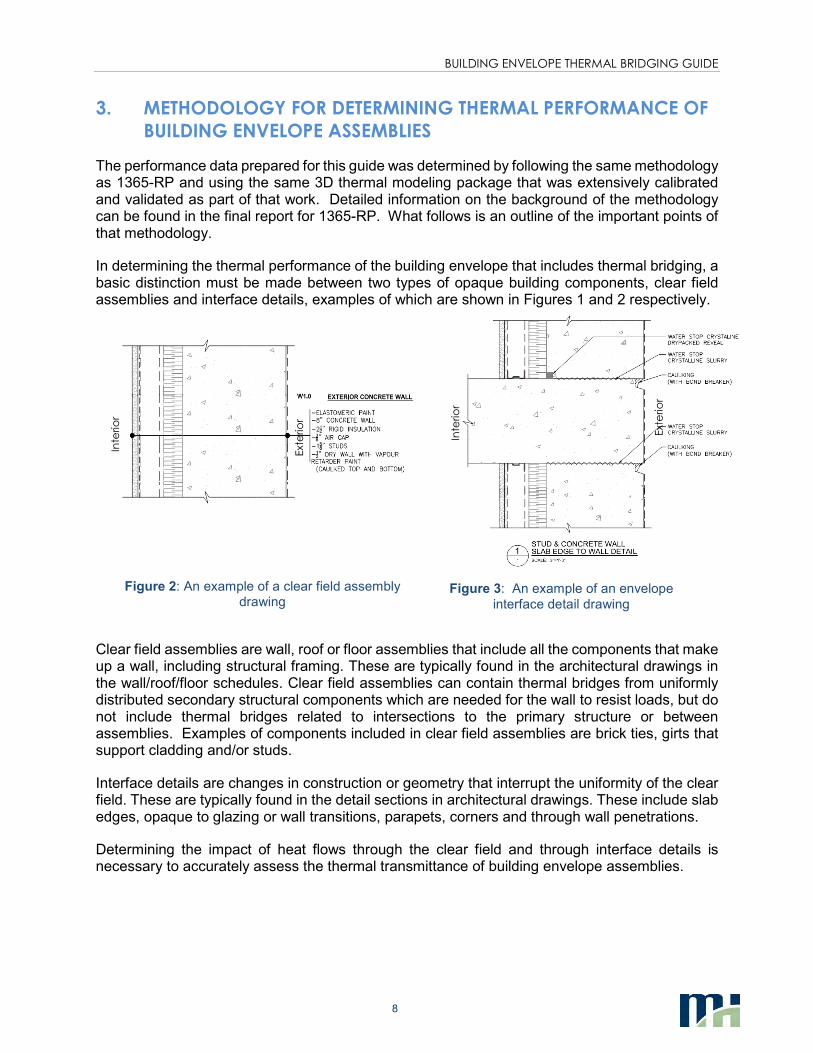
In determining the thermal performance of the building envelope that includes thermal bridging, a basic distinction must be made between two types of opaque building components, clear field assemblies and interface details, examples of which are shown in Figures 1 and 2 respectively.
Figure 3: An example of an envelope
interface detail drawing
Clear field assemblies are wall, roof or floor assemblies that include all the components that make up a wall, including structural framing. These are typically found in the architectural drawings in the wall/roof/floor schedules. Clear field assemblies can contain thermal bridges from uniformly distributed secondary structural components which are needed for the wall to resist loads, but do not include thermal bridges related to intersections to the primary structure or between assemblies. Examples of components included in clear field assemblies are brick ties, girts that support cladding and/or studs.
Interface details are changes in construction or geometry that interrupt the uniformity of the clear field. These are typically found in the detail sections in architectural drawings. These include slab edges, opaque to glazing or wall transitions, parapets, corners and through wall penetrations.
Determining the impact of heat flows through the clear field and through interface details is necessary to accurately assess the thermal transmittance of building envelope assemblies.
Inte
rio
r
Ext
erio
r
Ext
erio
r
Inte
rio
r
Figure 2: An example of a clear field assembly drawing
BUILDING ENVELOPE THERMAL BRIDGING GUIDE
9
A Note on Glazing
Glazing in buildings can have an incredibly large influence on building energy use, especially in designs
that have high window to wall ratios. Glazing portions of the building envelope are often dealt with
separately from the opaque elements because of the additional effects of solar heat gain. Thermal
analysis and testing of glazing systems in North America typically follow standards by the National
Fenestration Rating Council (Mitchell, et al., Rev 2013). Following this guide to determine the thermal
performance of opaque elements and NFRC standards for glazing is compatible. While the thermal
performance of glazing assemblies can affect the thermal resistance of adjacent wall or roof
assemblies, the heat loss is accounted for through the window to wall transition thermal values
described later in this guide.
3.1 DETERMINING THERMAL PERFORMANCE OF CLEAR FIELD ASSEMBLIES
The thermal performance of clear field assemblies can be determined through calculation, modeling or physical testing. Typically this takes the form of a U-value or effective R-value.
• The ASHRAE Handbook of Fundamentals (ASHRAE, 2013) provides several methods to determine clear field U-values using hand calculations. These hand calculations are meant for simple assemblies with only thermal bridges in one or two dimensions. These methods are described in more detail in the Handbook of Fundamentals.
• For assemblies where the 2D heat flow paths can influence each other and are more complex than appropriate for hand calculations, then 2D thermal modeling can be utilized to approximate the thermal performance of building envelope details. Software for this type of modeling (such as THERM, (Mitchell, et al., Rev 2013) is widely available and used in industry for two-dimensional thermal modeling. Approximations need to be made for components that are not continuous or occur in three dimensions, such as creating an equivalent thermal conductivity. These approximations can be sufficient in many cases for determining the expected thermal transmittance of opaque assemblies, but cannot be used to determine surface temperatures.
• For complex geometries and configurations where 2D heat flow assumptions are no longer valid, then 3D modeling or physical testing is often necessary for more accurate approximations of thermal performance. As stated previously, the clear field and detail values prepared for this guide were determined through 3D modeling.
It is typically only necessary to model or test a clear wall assembly if it is a new or unique design when information is not available. The construction industry has a wide variety of resources accessible to designers which contain thermal performance values for many types of clear field assemblies. Clear field assemblies analyzed for this guide are discussed in section 1.3.1 with additional information and thermal performance values provided in Appendices A and B. Other sources of information beyond this guide are discussed further in section 1.3.3.
BUILDING ENVELOPE THERMAL BRIDGING GUIDE
10
3.2 DETERMINING THERMAL PERFORMANCE OF INTERFACE DETAILS – AREA
WEIGHTED APPROACH
Area weighted calculations are commonly used to calculate U-values or effective R-values of the combined effect of assemblies and interface details. Typically, this is done by weighting the heat flow through the materials by the area they take up. While this can be applied easily to simple clear field assemblies, the question that arises when applied to interface details is what is the area of a thermal bridge?
Using only the physical area of a thermal bridge assumes that the heat flow paths through an interface detail are one-dimensional and parallel. Unfortunately, this is rarely true, and highly conductive building components create lateral heat flows to other components in three dimensions that are not accounted for in basic parallel flow assumptions. A steel shelf angle holding up a brick wall may seem small from the outside, but it is connected to many other components behind the brick and heat can easily flow around the insulation.
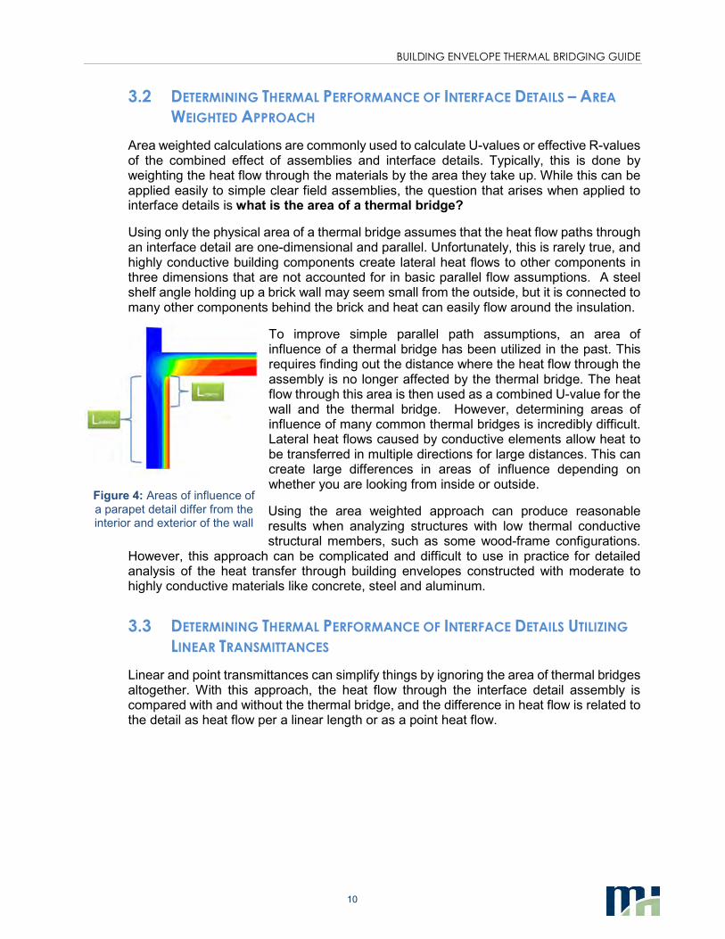
To improve simple parallel path assumptions, an area of influence of a thermal bridge has been utilized in the past. This requires finding out the distance where the heat flow through the assembly is no longer affected by the thermal bridge. The heat flow through this area is then used as a combined U-value for the wall and the thermal bridge. However, determining areas of influence of many common thermal bridges is incredibly difficult. Lateral heat flows caused by conductive elements allow heat to be transferred in multiple directions for large distances. This can create large differences in areas of influence depending on whether you are looking from inside or outside.
Using the area weighted approach can produce reasonable results when analyzing structures with low thermal conductive structural members, such as some wood-frame configurations.
However, this approach can be complicated and difficult to use in practice for detailed analysis of the heat transfer through building envelopes constructed with moderate to highly conductive materials like concrete, steel and aluminum.
3.3 DETERMINING THERMAL PERFORMANCE OF INTERFACE DETAILS UTILIZING
LINEAR TRANSMITTANCES
Linear and point transmittances can simplify things by ignoring the area of thermal bridges altogether. With this approach, the heat flow through the interface detail assembly is compared with and without the thermal bridge, and the difference in heat flow is related to the detail as heat flow per a linear length or as a point heat flow.
Figure 4: Areas of influence of a parapet detail differ from the interior and exterior of the wall
BUILDING ENVELOPE THERMAL BRIDGING GUIDE
11
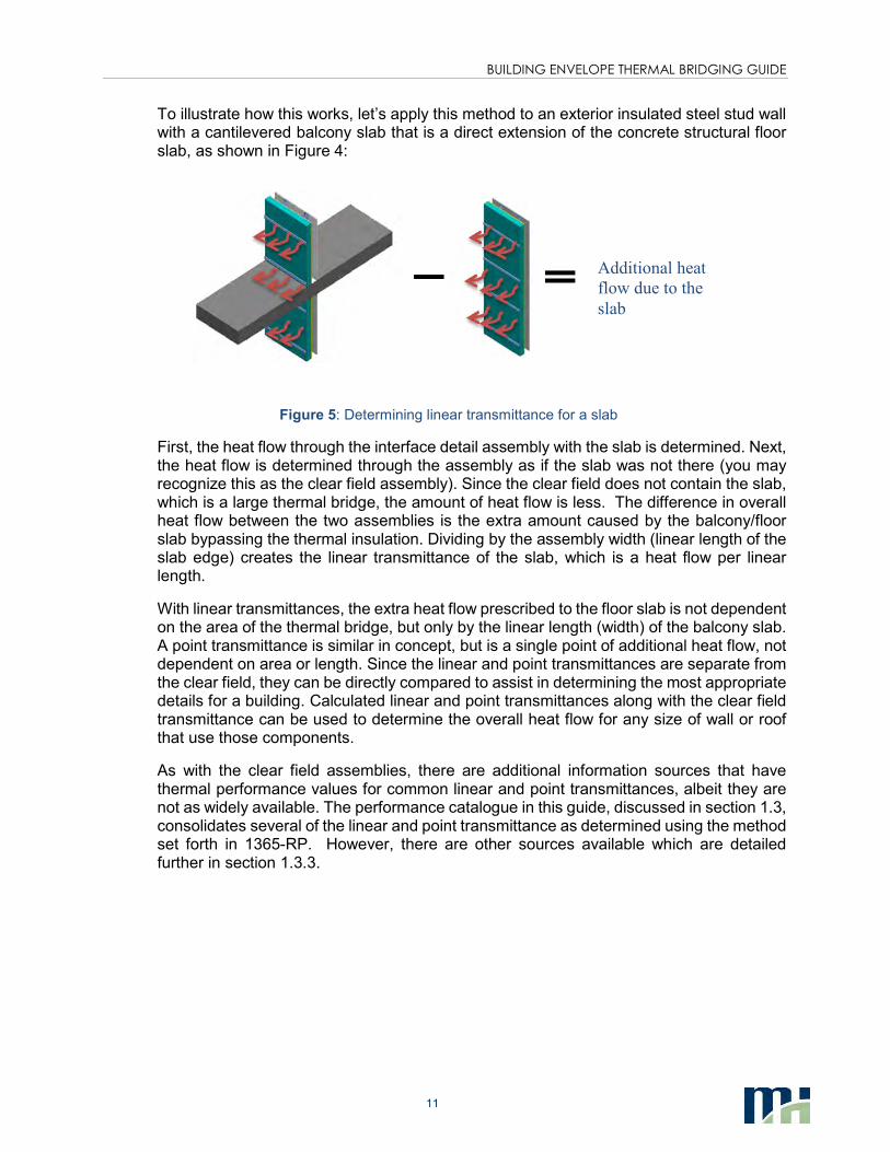
To illustrate how this works, let’s apply this method to an exterior insulated steel stud wall with a cantilevered balcony slab that is a direct extension of the concrete structural floor slab, as shown in Figure 4:
Figure 5: Determining linear transmittance for a slab
First, the heat flow through the interface detail assembly with the slab is determined. Next, the heat flow is determined through the assembly as if the slab was not there (you may recognize this as the clear field assembly). Since the clear field does not contain the slab, which is a large thermal bridge, the amount of heat flow is less. The difference in overall heat flow between the two assemblies is the extra amount caused by the balcony/floor slab bypassing the thermal insulation. Dividing by the assembly width (linear length of the slab edge) creates the linear transmittance of the slab, which is a heat flow per linear length.
With linear transmittances, the extra heat flow prescribed to the floor slab is not dependent on the area of the thermal bridge, but only by the linear length (width) of the balcony slab. A point transmittance is similar in concept, but is a single point of additional heat flow, not dependent on area or length. Since the linear and point transmittances are separate from the clear field, they can be directly compared to assist in determining the most appropriate details for a building. Calculated linear and point transmittances along with the clear field transmittance can be used to determine the overall heat flow for any size of wall or roof that use those components.
As with the clear field assemblies, there are additional information sources that have thermal performance values for common linear and point transmittances, albeit they are not as widely available. The performance catalogue in this guide, discussed in section 1.3, consolidates several of the linear and point transmittance as determined using the method set forth in 1365-RP. However, there are other sources available which are detailed further in section 1.3.3.
Additional heat
flow due to the
slab
BUILDING ENVELOPE THERMAL BRIDGING GUIDE
12
Superimposing Heat Flows Another way of looking at the basic concept of linear
transmittance is by superimposing the heat flows from
the full assembly, with an interface detail, and the
clear field assembly, without the interface detail, over
top of each other.
From this figure you can visualize the lateral heat flows
to the path of least resistance through the interface
detail assembly (i.e. through the slab). This results in a
higher heat flow at the slab compared to if it was only
the clear field. Far away enough from the slab and the
heat flow reaches the same level as in the clear field.
By subtracting the clear field from the total interface detail assembly leaves the additional heat
flow from just the slab, from which we get the linear transmittance.
3.4 DETERMINING OVERALL THERMAL PERFORMANCE
The thermal performance values of each of the envelope components can be used to calculate an overall thermal transmittance (U-value) for building envelope assemblies that include thermal bridging. Summarizing the approach so far, the thermal transmittances used in the calculations comprise of three separate categories:
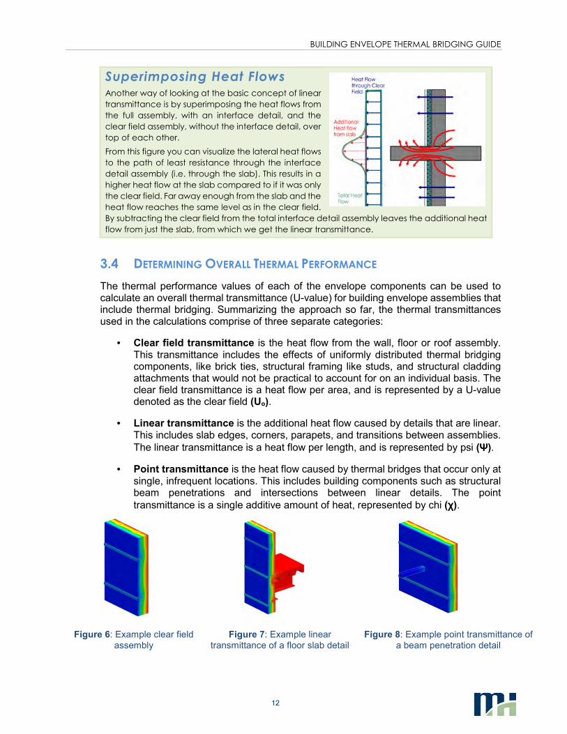
• Clear field transmittance is the heat flow from the wall, floor or roof assembly. This transmittance includes the effects of uniformly distributed thermal bridging components, like brick ties, structural framing like studs, and structural cladding attachments that would not be practical to account for on an individual basis. The clear field transmittance is a heat flow per area, and is represented by a U-value denoted as the clear field (Uo).
• Linear transmittance is the additional heat flow caused by details that are linear. This includes slab edges, corners, parapets, and transitions between assemblies.
The linear transmittance is a heat flow per length, and is represented by psi (ΨΨΨΨ).
• Point transmittance is the heat flow caused by thermal bridges that occur only at single, infrequent locations. This includes building components such as structural beam penetrations and intersections between linear details. The point
transmittance is a single additive amount of heat, represented by chi (χχχχ).
Figure 6: Example clear field
assembly
Figure 7: Example linear
transmittance of a floor slab detail
Figure 8: Example point transmittance of
a beam penetration detail
BUILDING ENVELOPE THERMAL BRIDGING GUIDE
13
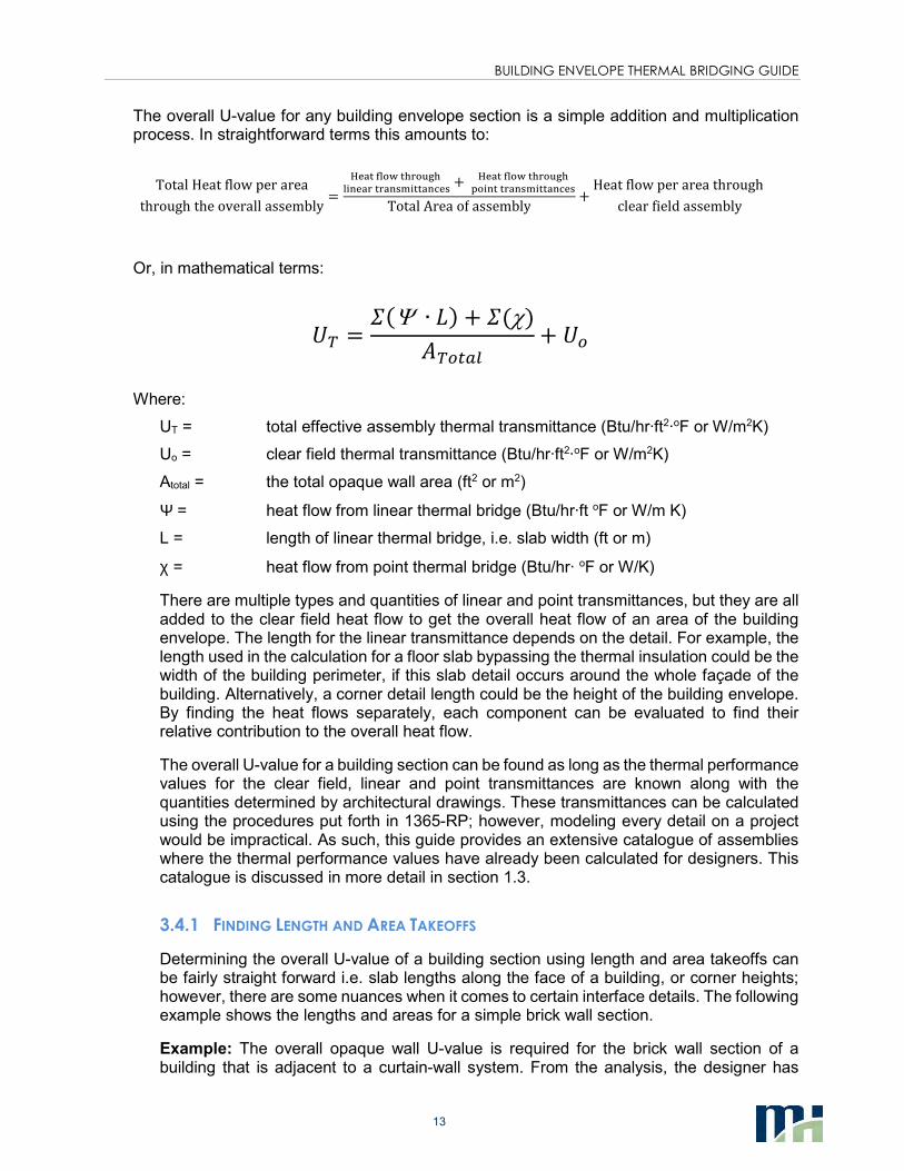
The overall U-value for any building envelope section is a simple addition and multiplication process. In straightforward terms this amounts to:
TotalHeatflowperarea
throughtheoverallassembly=
������������ !�
�"#������#$%"���#&�$+
������������ !�
(�"#����#$%"���#&�$
TotalAreaofassembly+Heatflowperareathrough
clearfieldassembly
Or, in mathematical terms:
-. =/0Ψ ∙ 23 + /0χ3
4.5678+ -5
Where:
UT = total effective assembly thermal transmittance (Btu/hr·ft2·oF or W/m2K)
Uo = clear field thermal transmittance (Btu/hr·ft2·oF or W/m2K)
Atotal = the total opaque wall area (ft2 or m2)
Ψ = heat flow from linear thermal bridge (Btu/hr·ft oF or W/m K)
L = length of linear thermal bridge, i.e. slab width (ft or m)
χ = heat flow from point thermal bridge (Btu/hr· oF or W/K)
There are multiple types and quantities of linear and point transmittances, but they are all added to the clear field heat flow to get the overall heat flow of an area of the building envelope. The length for the linear transmittance depends on the detail. For example, the length used in the calculation for a floor slab bypassing the thermal insulation could be the width of the building perimeter, if this slab detail occurs around the whole façade of the building. Alternatively, a corner detail length could be the height of the building envelope. By finding the heat flows separately, each component can be evaluated to find their relative contribution to the overall heat flow.
The overall U-value for a building section can be found as long as the thermal performance values for the clear field, linear and point transmittances are known along with the quantities determined by architectural drawings. These transmittances can be calculated using the procedures put forth in 1365-RP; however, modeling every detail on a project would be impractical. As such, this guide provides an extensive catalogue of assemblies where the thermal performance values have already been calculated for designers. This catalogue is discussed in more detail in section 1.3.
3.4.1 FINDING LENGTH AND AREA TAKEOFFS
Determining the overall U-value of a building section using length and area takeoffs can be fairly straight forward i.e. slab lengths along the face of a building, or corner heights; however, there are some nuances when it comes to certain interface details. The following example shows the lengths and areas for a simple brick wall section.
Example: The overall opaque wall U-value is required for the brick wall section of a building that is adjacent to a curtain-wall system. From the analysis, the designer has
BUILDING ENVELOPE THERMAL BRIDGING GUIDE
14
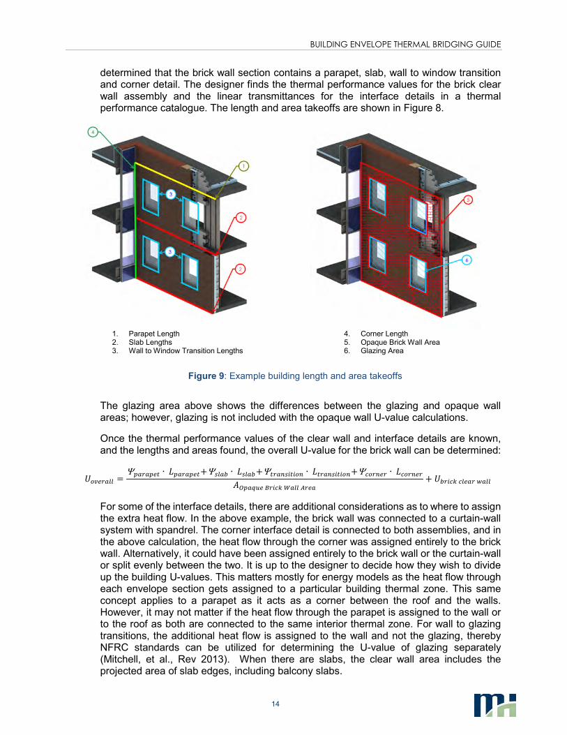
determined that the brick wall section contains a parapet, slab, wall to window transition and corner detail. The designer finds the thermal performance values for the brick clear wall assembly and the linear transmittances for the interface details in a thermal performance catalogue. The length and area takeoffs are shown in Figure 8.
1. Parapet Length 2. Slab Lengths 3. Wall to Window Transition Lengths
4. Corner Length 5. Opaque Brick Wall Area 6. Glazing Area
Figure 9: Example building length and area takeoffs
The glazing area above shows the differences between the glazing and opaque wall areas; however, glazing is not included with the opaque wall U-value calculations.
Once the thermal performance values of the clear wall and interface details are known, and the lengths and areas found, the overall U-value for the brick wall can be determined:
-59:;788 =Ψ<7;7<:6 ∙ 2<7;7<:6+Ψ=87> ∙ 2=87>+Ψ6;7?=@6@5? ∙ 26;7?=@6@5?+ΨA5;?:; ∙ 2A5;?:;
4B<7CD:E;@AFG788H;:7
+ ->;@AFA8:7;I788
For some of the interface details, there are additional considerations as to where to assign the extra heat flow. In the above example, the brick wall was connected to a curtain-wall system with spandrel. The corner interface detail is connected to both assemblies, and in the above calculation, the heat flow through the corner was assigned entirely to the brick wall. Alternatively, it could have been assigned entirely to the brick wall or the curtain-wall or split evenly between the two. It is up to the designer to decide how they wish to divide up the building U-values. This matters mostly for energy models as the heat flow through each envelope section gets assigned to a particular building thermal zone. This same concept applies to a parapet as it acts as a corner between the roof and the walls. However, it may not matter if the heat flow through the parapet is assigned to the wall or to the roof as both are connected to the same interior thermal zone. For wall to glazing transitions, the additional heat flow is assigned to the wall and not the glazing, thereby NFRC standards can be utilized for determining the U-value of glazing separately (Mitchell, et al., Rev 2013). When there are slabs, the clear wall area includes the projected area of slab edges, including balcony slabs.
BUILDING ENVELOPE THERMAL BRIDGING GUIDE
15
Length and Area Takeoffs and the Plane of Heat Transfer
The plane of heat transfer for the building
envelope is a theoretical projected area
between the interior and exterior conditions
through which heat flows. In order for there to
be a heat loss or heat gain through the
building envelope, energy must pass through
this plane of heat transfer. A building
assembly may have some elaborate features
that extend out past the building envelope;
however, all that is important for thermal
performance is where the heat flow passes
the plane of heat transfer into or out of the
building.
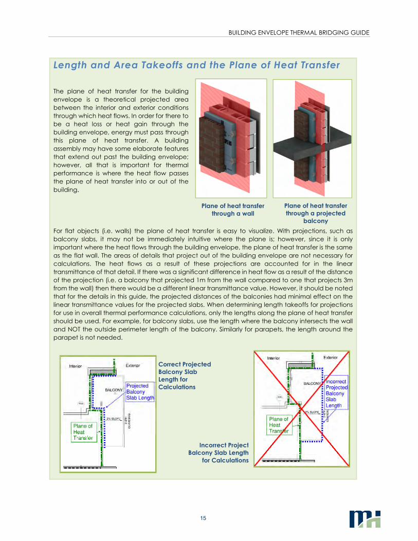
For flat objects (i.e. walls) the plane of heat transfer is easy to visualize. With projections, such as
balcony slabs, it may not be immediately intuitive where the plane is; however, since it is only
important where the heat flows through the building envelope, the plane of heat transfer is the same
as the flat wall. The areas of details that project out of the building envelope are not necessary for
calculations. The heat flows as a result of these projections are accounted for in the linear
transmittance of that detail. If there was a significant difference in heat flow as a result of the distance
of the projection (i.e. a balcony that projected 1m from the wall compared to one that projects 3m
from the wall) then there would be a different linear transmittance value. However, it should be noted
that for the details in this guide, the projected distances of the balconies had minimal effect on the
linear transmittance values for the projected slabs. When determining length takeoffs for projections
for use in overall thermal performance calculations, only the lengths along the plane of heat transfer
should be used. For example, for balcony slabs, use the length where the balcony intersects the wall
and NOT the outside perimeter length of the balcony. Similarly for parapets, the length around the
parapet is not needed.
Plane of heat transfer
through a wall
Plane of heat transfer
through a projected
balcony
Correct Projected
Balcony Slab
Length for
Calculations
Incorrect Project
Balcony Slab Length
for Calculations
BUILDING ENVELOPE THERMAL BRIDGING GUIDE
16
A Note on Length and Area Takeoffs for the Detail Oriented
The lengths for linear transmittances are usually
easiest to find using building elevation drawings,
which are exterior dimensions. Some further
investigation for take offs may be required, such as
looking at interior section views, when a detail is
obstructed by other building features (i.e. the
cladding). However, getting the takeoff lengths and
areas from the exterior or the interior dimensions will
result in slight differences on the overall U-value,
depending on how the linear transmittances are
reported. The way in which the linear transmittances
are reported for this guide are such that if mixed
interior and exterior dimensions are used, then the U-
values will be slightly more conservative. This is
typically not a concern as the differences from mixing
interior and exterior dimensions are minor and there
are already inherent discrepancies between
architectural drawings and what is built on site. The following information is for those designers who want that extra level
of precision.
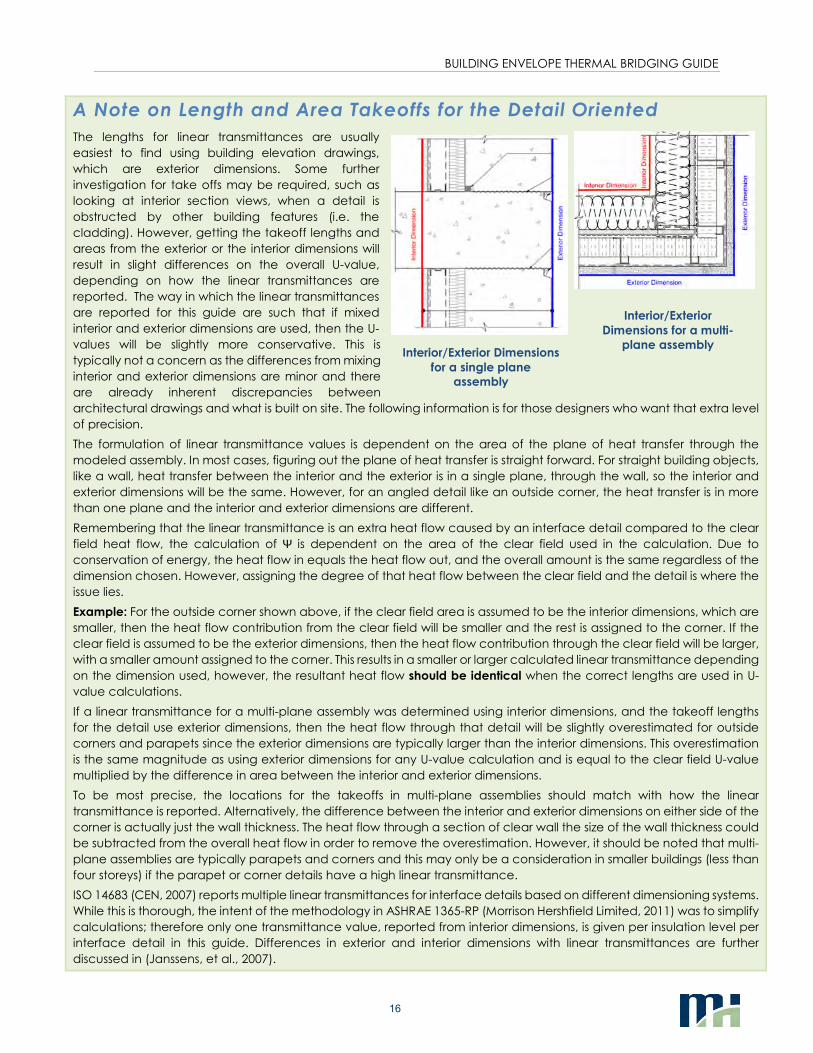
The formulation of linear transmittance values is dependent on the area of the plane of heat transfer through the
modeled assembly. In most cases, figuring out the plane of heat transfer is straight forward. For straight building objects,
like a wall, heat transfer between the interior and the exterior is in a single plane, through the wall, so the interior and
exterior dimensions will be the same. However, for an angled detail like an outside corner, the heat transfer is in more
than one plane and the interior and exterior dimensions are different.
Remembering that the linear transmittance is an extra heat flow caused by an interface detail compared to the clear
field heat flow, the calculation of Ψ is dependent on the area of the clear field used in the calculation. Due to
conservation of energy, the heat flow in equals the heat flow out, and the overall amount is the same regardless of the
dimension chosen. However, assigning the degree of that heat flow between the clear field and the detail is where the
issue lies.
Example: For the outside corner shown above, if the clear field area is assumed to be the interior dimensions, which are
smaller, then the heat flow contribution from the clear field will be smaller and the rest is assigned to the corner. If the
clear field is assumed to be the exterior dimensions, then the heat flow contribution through the clear field will be larger,
with a smaller amount assigned to the corner. This results in a smaller or larger calculated linear transmittance depending
on the dimension used, however, the resultant heat flow should be identical when the correct lengths are used in U-
value calculations.
If a linear transmittance for a multi-plane assembly was determined using interior dimensions, and the takeoff lengths
for the detail use exterior dimensions, then the heat flow through that detail will be slightly overestimated for outside
corners and parapets since the exterior dimensions are typically larger than the interior dimensions. This overestimation
is the same magnitude as using exterior dimensions for any U-value calculation and is equal to the clear field U-value
multiplied by the difference in area between the interior and exterior dimensions.
To be most precise, the locations for the takeoffs in multi-plane assemblies should match with how the linear
transmittance is reported. Alternatively, the difference between the interior and exterior dimensions on either side of the
corner is actually just the wall thickness. The heat flow through a section of clear wall the size of the wall thickness could
be subtracted from the overall heat flow in order to remove the overestimation. However, it should be noted that multi-
plane assemblies are typically parapets and corners and this may only be a consideration in smaller buildings (less than
four storeys) if the parapet or corner details have a high linear transmittance.
ISO 14683 (CEN, 2007) reports multiple linear transmittances for interface details based on different dimensioning systems.
While this is thorough, the intent of the methodology in ASHRAE 1365-RP (Morrison Hershfield Limited, 2011) was to simplify
calculations; therefore only one transmittance value, reported from interior dimensions, is given per insulation level per
interface detail in this guide. Differences in exterior and interior dimensions with linear transmittances are further
discussed in (Janssens, et al., 2007).
Interior/Exterior Dimensions
for a single plane
assembly
Interior/Exterior
Dimensions for a multi-
plane assembly
BUILDING ENVELOPE THERMAL BRIDGING GUIDE
17
Dealing with Floor to Ceiling Glazing
An issue that arises when determining lengths and areas for heat loss calculations is glazing that spans floor
to ceiling. In the methodology presented in the guide, glazing and opaque envelope areas are accounted
for separately when calculating heat loss, with additional heat loss from interface details added to the
opaque areas. Thus, a situation arises when there is floor to ceiling glazing from slab to slab and there is no
discernible opaque clear wall area.
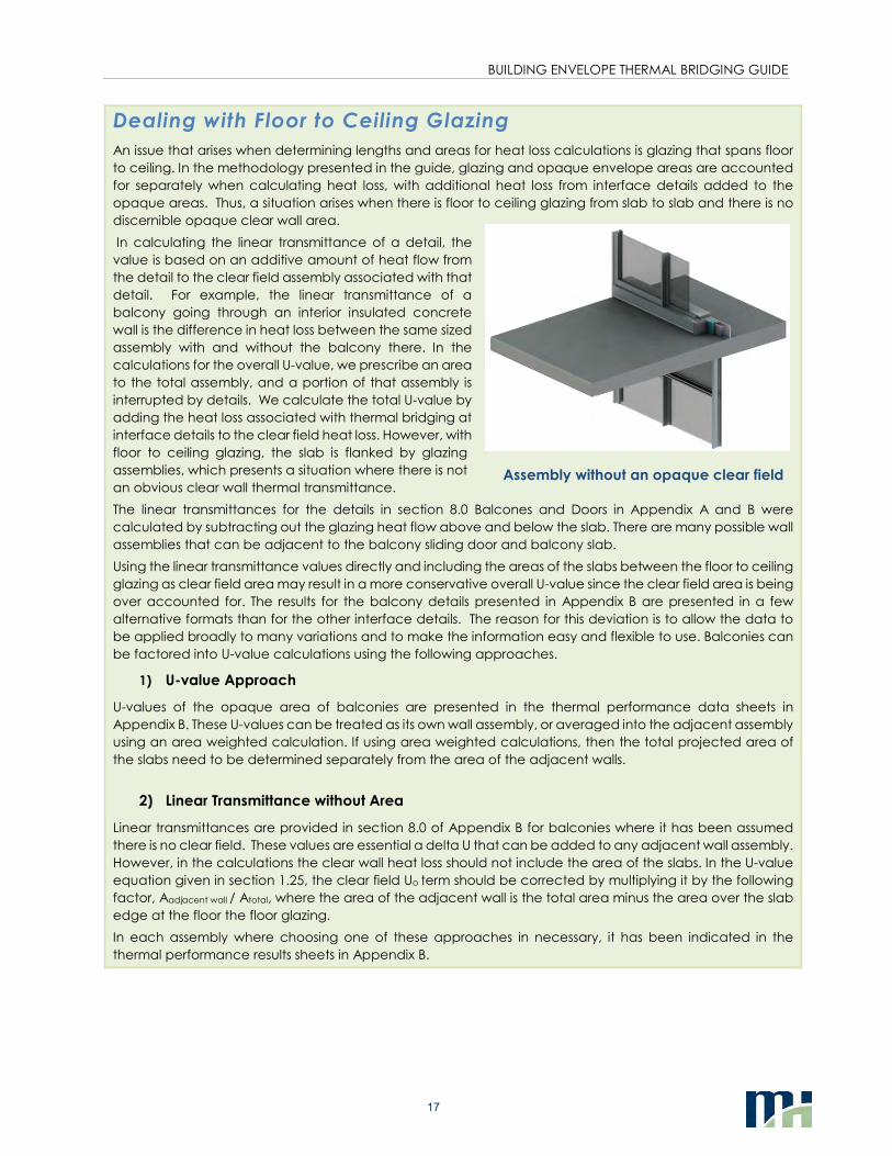
In calculating the linear transmittance of a detail, the
value is based on an additive amount of heat flow from
the detail to the clear field assembly associated with that
detail. For example, the linear transmittance of a
balcony going through an interior insulated concrete
wall is the difference in heat loss between the same sized
assembly with and without the balcony there. In the
calculations for the overall U-value, we prescribe an area
to the total assembly, and a portion of that assembly is
interrupted by details. We calculate the total U-value by
adding the heat loss associated with thermal bridging at
interface details to the clear field heat loss. However, with
floor to ceiling glazing, the slab is flanked by glazing
assemblies, which presents a situation where there is not
an obvious clear wall thermal transmittance.
The linear transmittances for the details in section 8.0 Balcones and Doors in Appendix A and B were
calculated by subtracting out the glazing heat flow above and below the slab. There are many possible wall
assemblies that can be adjacent to the balcony sliding door and balcony slab.
Using the linear transmittance values directly and including the areas of the slabs between the floor to ceiling
glazing as clear field area may result in a more conservative overall U-value since the clear field area is being
over accounted for. The results for the balcony details presented in Appendix B are presented in a few
alternative formats than for the other interface details. The reason for this deviation is to allow the data to
be applied broadly to many variations and to make the information easy and flexible to use. Balconies can
be factored into U-value calculations using the following approaches.
1) U-value Approach
U-values of the opaque area of balconies are presented in the thermal performance data sheets in
Appendix B. These U-values can be treated as its own wall assembly, or averaged into the adjacent assembly
using an area weighted calculation. If using area weighted calculations, then the total projected area of
the slabs need to be determined separately from the area of the adjacent walls.
2) Linear Transmittance without Area
Linear transmittances are provided in section 8.0 of Appendix B for balconies where it has been assumed
there is no clear field. These values are essential a delta U that can be added to any adjacent wall assembly.
However, in the calculations the clear wall heat loss should not include the area of the slabs. In the U-value
equation given in section 1.25, the clear field Uo term should be corrected by multiplying it by the following
factor, Aadjacent wall / Atotal, where the area of the adjacent wall is the total area minus the area over the slab
edge at the floor the floor glazing.
In each assembly where choosing one of these approaches in necessary, it has been indicated in the
thermal performance results sheets in Appendix B.
Assembly without an opaque clear field
BUILDING ENVELOPE THERMAL BRIDGING GUIDE
18
4. SUMMARY OF THE THERMAL PERFORMANCE CATALOGUE
4.1 CATALOGUE BREAKDOWN
The catalogue prepared for this guide contains extensive thermal performance information on numerous common details, along with details intended to mitigate thermal bridging, including some emerging technologies and products. This data was calculated using the methodology from 1365-RP (including air films), as summarized in Section 1.2. The catalogue also contains thermal performance information from ASHRAE 1365-RP, along with other details previously analyzed by Morrison Hershfield Ltd. The catalogue is broken into two main sections:
• Appendix A contains an overview of the assemblies and interface details. This includes isometric drawings, dimensions and material properties.
• Appendix B contains the thermal performance information. This includes clear field, linear and point transmittance values, where applicable, along with overall U-values for the modeled assembly sizes and temperature indices.
The catalogue have been organized first by construction type as follows:
1. Window-wall
2. Conventional Curtain-wall
3. Unitized
4. Curtain-wall
5. High Performance Curtain-wall
6. Steel Stud Construction
7. Concrete Construction
8. Wood Frame Construction
9. Doors and Balconies
10. Roofs
Within each construction type category the assemblies have been organized by transmittance type. Table 1 summarizes the types of transmittances that are featured in the catalogue. A more detailed discussion on the catalogue information is given at the beginning of Appendices A and B.
BUILDING ENVELOPE THERMAL BRIDGING GUIDE
19
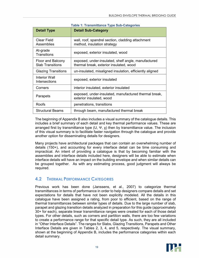
Table 1: Transmittance Type Sub-Categories
Detail Type Detail Sub-Category
Clear Field Assemblies
wall, roof, spandrel section, cladding attachment method, insulation strategy
At-grade Transitions
exposed, exterior insulated, wood
Floor and Balcony Slab Transitions
exposed, under-insulated, shelf angle, manufactured thermal break, exterior insulated, wood
Glazing Transitions un-insulated, misaligned insulation, efficiently aligned
Interior Wall Intersections
exposed, exterior insulated
Corners interior insulated, exterior insulated
Parapets exposed, under-insulated, manufactured thermal break, exterior insulated, wood
Roofs penetrations, transitions
Structural Beams through beam, manufactured thermal break
The beginning of Appendix B also includes a visual summary of the catalogue details. This includes a brief summary of each detail and key thermal performance values. These are
arranged first by transmittance type (U, Ψ, χ) then by transmittance value. The inclusion of this visual summary is to facilitate faster navigation through the catalogue and provide another option for disseminating details for designers.
Many projects have architectural packages that can contain an overwhelming number of details (150+), and accounting for every interface detail can be time consuming and impractical. An intent of providing a catalogue is that by becoming familiar with the assemblies and interface details included here, designers will be able to estimate when interface details will have an impact on the building envelope and when similar details can be grouped together. As with any estimating process, good judgment will always be required.
4.2 THERMAL PERFORMANCE CATEGORIES
Previous work has been done (Janssens, et al., 2007) to categorize thermal transmittances in terms of performance in order to help designers compare details and set expectations for details that have not been explicitly modeled. All the details in this catalogue have been assigned a rating, from poor to efficient, based on the range of thermal transmittances between similar types of details. Due to the large number of slab, parapet and glazing transition details analyzed in preparation for this guide (approximately 30+ for each), separate linear transmittance ranges were created for each of those detail types. For other details, such as corners and partition walls, there are too few variations to create a performance range for that specific detail type. As such, they are all included in “Other Interface Details”. The ranges for Slabs, Glazing Transitions, Parapets and Other Interface Details are given in Tables 2, 3, 4, and 5, respectively. The visual summary, shown at the beginning of Appendix B, includes the performance categories within each detail summary.
BUILDING ENVELOPE THERMAL BRIDGING GUIDE
20
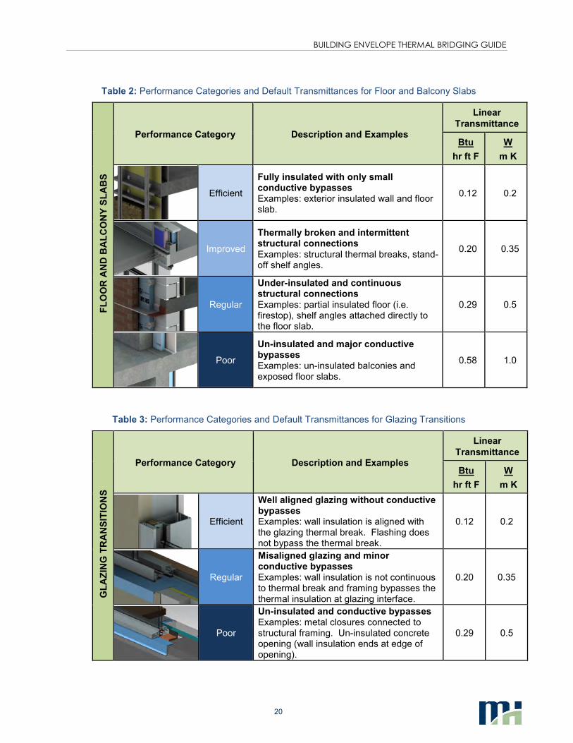
Table 2: Performance Categories and Default Transmittances for Floor and Balcony Slabs
FL
OO
R A
ND
BA
LC
ON
Y S
LA
BS
Performance Category Description and Examples
Linear
Transmittance
Btu
hr ft F
W
m K
Efficient
Fully insulated with only small conductive bypasses Examples: exterior insulated wall and floor slab.
0.12 0.2
Improved
Thermally broken and intermittent structural connections Examples: structural thermal breaks, stand-off shelf angles.
0.20 0.35
Regular
Under-insulated and continuous structural connections Examples: partial insulated floor (i.e. firestop), shelf angles attached directly to the floor slab.
0.29 0.5
Poor
Un-insulated and major conductive bypasses Examples: un-insulated balconies and exposed floor slabs.
0.58 1.0
Table 3: Performance Categories and Default Transmittances for Glazing Transitions
GL
AZ
ING
TR
AN
SIT
ION
S
Performance Category Description and Examples
Linear
Transmittance
Btu
hr ft F
W
m K
Efficient
Well aligned glazing without conductive bypasses Examples: wall insulation is aligned with the glazing thermal break. Flashing does not bypass the thermal break.
0.12 0.2
Regular
Misaligned glazing and minor conductive bypasses Examples: wall insulation is not continuous to thermal break and framing bypasses the thermal insulation at glazing interface.
0.20 0.35
Poor
Un-insulated and conductive bypasses Examples: metal closures connected to structural framing. Un-insulated concrete opening (wall insulation ends at edge of opening).
0.29 0.5
BUILDING ENVELOPE THERMAL BRIDGING GUIDE
21
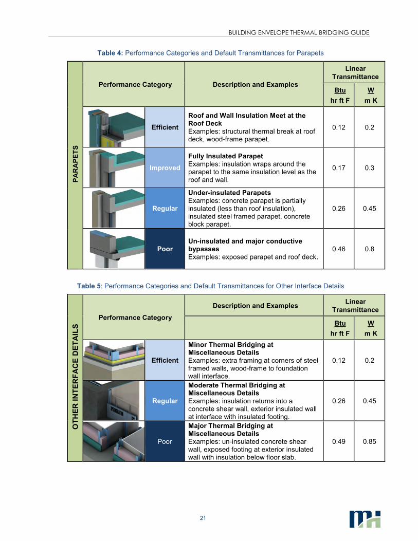
Table 4: Performance Categories and Default Transmittances for Parapets
PA
RA
PE
TS
Performance Category Description and Examples
Linear
Transmittance
Btu
hr ft F
W
m K
Efficient
Roof and Wall Insulation Meet at the Roof Deck Examples: structural thermal break at roof deck, wood-frame parapet.
0.12 0.2
Improved
Fully Insulated Parapet Examples: insulation wraps around the parapet to the same insulation level as the roof and wall.
0.17 0.3
Regular
Under-insulated Parapets Examples: concrete parapet is partially insulated (less than roof insulation), insulated steel framed parapet, concrete block parapet.
0.26 0.45
Poor Un-insulated and major conductive bypasses Examples: exposed parapet and roof deck.
0.46 0.8
Table 5: Performance Categories and Default Transmittances for Other Interface Details
OT
HE
R I
NT
ER
FA
CE
DE
TA
ILS
Performance Category
Description and Examples Linear
Transmittance
Btu
hr ft F
W
m K
Efficient
Minor Thermal Bridging at Miscellaneous Details Examples: extra framing at corners of steel framed walls, wood-frame to foundation wall interface.
0.12 0.2
Regular
Moderate Thermal Bridging at Miscellaneous Details Examples: insulation returns into a concrete shear wall, exterior insulated wall at interface with insulated footing.
0.26 0.45
Poor
Major Thermal Bridging at Miscellaneous Details Examples: un-insulated concrete shear wall, exposed footing at exterior insulated wall with insulation below floor slab.
0.49 0.85
BUILDING ENVELOPE THERMAL BRIDGING GUIDE
22
Rating details based on expected transmittance ranges has several uses:
1. Not every common interface detail has been evaluated and cataloged in this guide. Ranges help with estimating the order of magnitude of transmittance values for interface details that are not directly covered by the catalogue, without the need for further evaluation.
2. Some project specific interface details will still require further evaluation. The ranges for transmittances help set expectations for evaluating other interface details.
3. Ratings can establish default assumptions and/or set prescriptive requirements for the inclusion of interface details in codes and energy standards.
4. Similarly, ratings can establish values for the baseline buildings of the performance compliance paths in energy standards and/or performance rating programs (for example LEED).
5. Ranges for interface details can help set thermal performance targets for the building envelope early in design. When included with a preliminary energy model (before details are even chosen) the ranges can show what can be expected from the building envelope based on a given construction type.
4.3 OTHER SOURCES OF INFORMATION
While the catalogue provided with this guide is extensive, there are additional sources to find thermal performance data for clear field assemblies and linear and point transmittances. Here are a few examples:
• Appendix A of ASHRAE 90.1 “Energy Standard for Buildings Except Low-Rise Residential” (ASHRAE, 2010) contains several tables of thermal performance values for a variety of clear field constructions, including walls, roofs and floors for concrete, steel framed and wood framed constructions. The values for many of the exterior insulated structures assume continuous insulation and do not account for cladding attachments which interrupt the exterior insulation.
• Manufacturers of proprietary systems, such as structural cladding attachments or curtain-wall systems, often have thermal performance data of their products. Upon request they can provide designers with the information. However, be aware that different manufacturers may calculate thermal performance using various procedures, sometimes making it difficult to compare different systems appropriately. If the manufacturer does not provide a full report on their thermal performance values, it may be prudent to request further information.
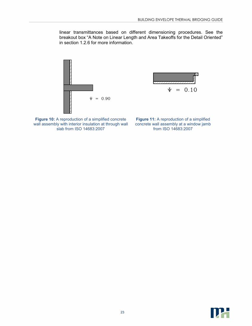
• In the absence of more specific information, ISO 14683:2007 “Thermal Bridges in Building Construction” (CEN, 2007) provides generic linear transmittances for simplified constructions. This standard outlines the methods of calculating linear transmission used in the European standards and provides an Annex with default Ψ values for many of the common interface details. The default values are based on very basic geometric shapes representing building components, as shown in Figures 9 and 10, resulting in conservative transmittance values. For example, complex heat flow paths created by misaligned glazing thermal breaks or flashing are not captured by these values. This standard also provides multiple
BUILDING ENVELOPE THERMAL BRIDGING GUIDE
23
linear transmittances based on different dimensioning procedures. See the breakout box “A Note on Linear Length and Area Takeoffs for the Detail Oriented” in section 1.2.6 for more information.
Figure 10: A reproduction of a simplified concrete wall assembly with interior insulation at through wall
slab from ISO 14683:2007
Figure 11: A reproduction of a simplified concrete wall assembly at a window jamb
from ISO 14683:2007
BUILDING ENVELOPE THERMAL BRIDGING GUIDE
24
5. EXAMPLE UTILIZATION OF THE CATALOGUE
In order to demonstrate how to utilize the catalogue in calculating overall U-values for a building, the following is a step-by-step example for a common Vancouver residential high-rise building.
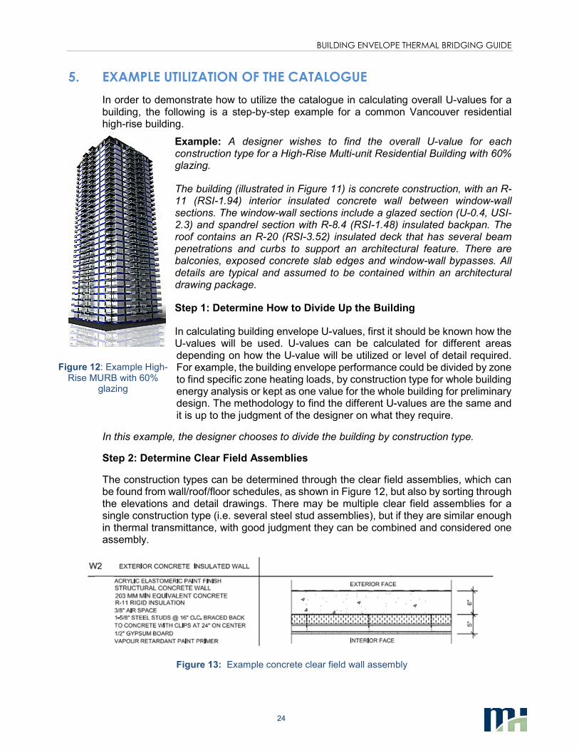
Example: A designer wishes to find the overall U-value for each construction type for a High-Rise Multi-unit Residential Building with 60% glazing.
The building (illustrated in Figure 11) is concrete construction, with an R-11 (RSI-1.94) interior insulated concrete wall between window-wall sections. The window-wall sections include a glazed section (U-0.4, USI-2.3) and spandrel section with R-8.4 (RSI-1.48) insulated backpan. The roof contains an R-20 (RSI-3.52) insulated deck that has several beam penetrations and curbs to support an architectural feature. There are balconies, exposed concrete slab edges and window-wall bypasses. All details are typical and assumed to be contained within an architectural drawing package.
Step 1: Determine How to Divide Up the Building
In calculating building envelope U-values, first it should be known how the U-values will be used. U-values can be calculated for different areas depending on how the U-value will be utilized or level of detail required. For example, the building envelope performance could be divided by zone to find specific zone heating loads, by construction type for whole building energy analysis or kept as one value for the whole building for preliminary design. The methodology to find the different U-values are the same and it is up to the judgment of the designer on what they require.
In this example, the designer chooses to divide the building by construction type.
Step 2: Determine Clear Field Assemblies
The construction types can be determined through the clear field assemblies, which can be found from wall/roof/floor schedules, as shown in Figure 12, but also by sorting through the elevations and detail drawings. There may be multiple clear field assemblies for a single construction type (i.e. several steel stud assemblies), but if they are similar enough in thermal transmittance, with good judgment they can be combined and considered one assembly.
Figure 13: Example concrete clear field wall assembly
Figure 12: Example High-Rise MURB with 60%
glazing
BUILDING ENVELOPE THERMAL BRIDGING GUIDE
25
For this example, from the architectural drawings, the designer finds there are three distinct construction types in the wall and roof schedules: Concrete Wall, Concrete Roof and Window-wall Spandrel.
Step 3: Determine Linear and Point Details
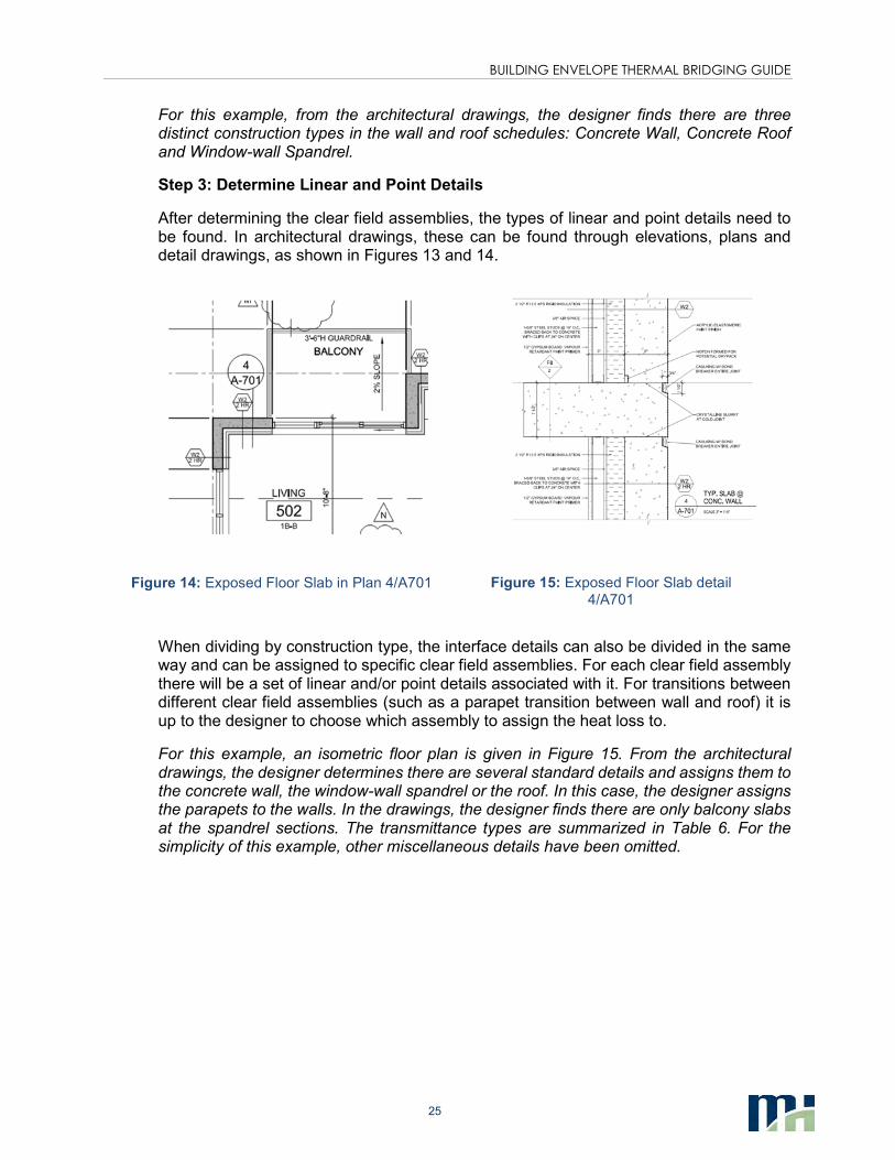
After determining the clear field assemblies, the types of linear and point details need to be found. In architectural drawings, these can be found through elevations, plans and detail drawings, as shown in Figures 13 and 14.
Figure 14: Exposed Floor Slab in Plan 4/A701
Figure 15: Exposed Floor Slab detail 4/A701
When dividing by construction type, the interface details can also be divided in the same way and can be assigned to specific clear field assemblies. For each clear field assembly there will be a set of linear and/or point details associated with it. For transitions between different clear field assemblies (such as a parapet transition between wall and roof) it is up to the designer to choose which assembly to assign the heat loss to.
For this example, an isometric floor plan is given in Figure 15. From the architectural drawings, the designer determines there are several standard details and assigns them to the concrete wall, the window-wall spandrel or the roof. In this case, the designer assigns the parapets to the walls. In the drawings, the designer finds there are only balcony slabs at the spandrel sections. The transmittance types are summarized in Table 6. For the simplicity of this example, other miscellaneous details have been omitted.
BUILDING ENVELOPE THERMAL BRIDGING GUIDE
26
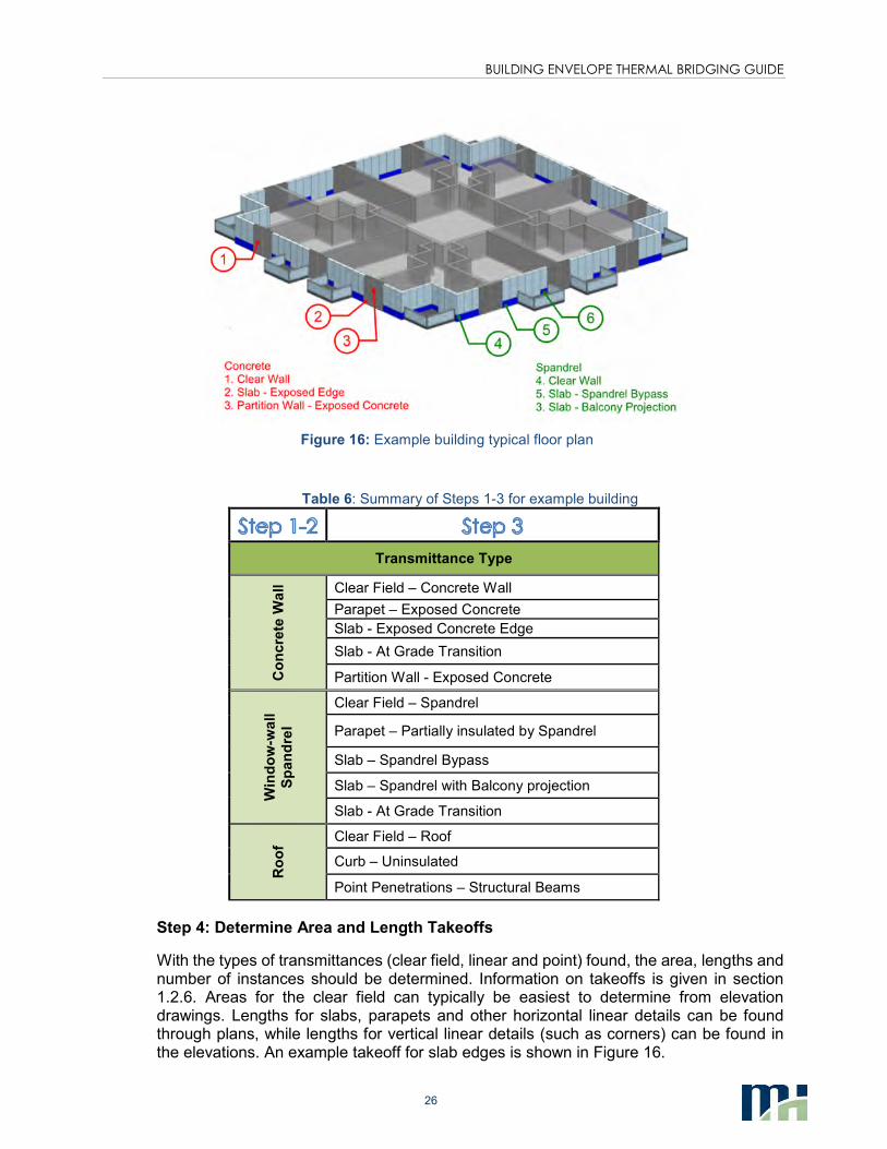
Figure 16: Example building typical floor plan
Table 6: Summary of Steps 1-3 for example building
Transmittance Type
Co
ncre
te W
all
Clear Field – Concrete Wall
Parapet – Exposed Concrete
Slab - Exposed Concrete Edge
Slab - At Grade Transition
Partition Wall - Exposed Concrete
Win
do
w-w
all
Sp
an
dre
l
Clear Field – Spandrel
Parapet – Partially insulated by Spandrel
Slab – Spandrel Bypass
Slab – Spandrel with Balcony projection
Slab - At Grade Transition
Ro
of
Clear Field – Roof
Curb – Uninsulated
Point Penetrations – Structural Beams
Step 4: Determine Area and Length Takeoffs
With the types of transmittances (clear field, linear and point) found, the area, lengths and number of instances should be determined. Information on takeoffs is given in section 1.2.6. Areas for the clear field can typically be easiest to determine from elevation drawings. Lengths for slabs, parapets and other horizontal linear details can be found through plans, while lengths for vertical linear details (such as corners) can be found in the elevations. An example takeoff for slab edges is shown in Figure 16.
BUILDING ENVELOPE THERMAL BRIDGING GUIDE
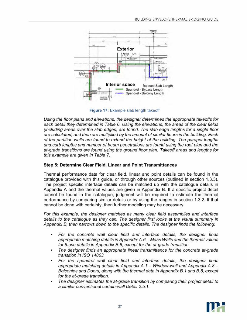
27
Figure 17: Example slab length takeoff
Using the floor plans and elevations, the designer determines the appropriate takeoffs for each detail they determined in Table 6. Using the elevations, the areas of the clear fields (including areas over the slab edges) are found. The slab edge lengths for a single floor are calculated, and then are multiplied by the amount of similar floors in the building. Each of the partition walls are found to extend the height of the building. The parapet lengths and curb lengths and number of beam penetrations are found using the roof plan and the at-grade transitions are found using the ground floor plan. Takeoff areas and lengths for this example are given in Table 7.
Step 5: Determine Clear Field, Linear and Point Transmittances
Thermal performance data for clear field, linear and point details can be found in the catalogue provided with this guide, or through other sources (outlined in section 1.3.3). The project specific interface details can be matched up with the catalogue details in Appendix A and the thermal values are given in Appendix B. If a specific project detail cannot be found in the catalogue, judgment will be required to estimate the thermal performance by comparing similar details or by using the ranges in section 1.3.2. If that cannot be done with certainty, then further modeling may be necessary.
For this example, the designer matches as many clear field assemblies and interface details to the catalogue as they can. The designer first looks at the visual summary in Appendix B, then narrows down to the specific details. The designer finds the following:
• For the concrete wall clear field and interface details, the designer finds appropriate matching details in Appendix A.6 – Mass Walls and the thermal values for those details in Appendix B.6, except for the at-grade transition.
• The designer finds an appropriate linear transmittance for the concrete at-grade transition in ISO 14863.
• For the spandrel wall clear field and interface details, the designer finds appropriate matching details in Appendix A.1 – Window-wall and Appendix A.8 – Balconies and Doors, along with the thermal data in Appendix B.1 and B.8, except for the at-grade transition.
• The designer estimates the at-grade transition by comparing their project detail to a similar conventional curtain-wall Detail 2.5.1.
Interior space
Exterior
BUILDING ENVELOPE THERMAL BRIDGING GUIDE
28
• The designer finds matching roof details in Appendix A.9 – Roofs along with the matching thermal data in Appendix B.9.
• The designer decides not enough information is available to estimate the roof penetrations and decides to have that detail modeled.
Detail references and transmittances for this example are given in Table 7.
Step 6 (Optional): Calculate Individual Transmittance Heat Flow
While not necessary to calculate the overall U-value, it may be advantageous for designers to calculate the individual heat flows associated with specific details to help make better design decisions and identify details that should be targeted. Recognizing components of the U-value equation given in section 1.2.5, the individual heat flows can be calculated using the following:
• Clear Field Heat Flow = Uo·A
• Linear Transmittance Heat Flow = Ψ·L
• Point Transmittance Heat Flow = χ·number of occurrences
For this example, the designer calculates the heat flow through the individual details to see which interface details have the largest impact on thermal performance. From that analysis the designer is able to determine which details should be a priority to improve. Individual heat flows for this example are given in Table 7.
Step 7: Calculate Overall U-Value
With all the transmittance values and takeoff areas/lengths known, the overall Wall/Roof U-values can be calculated using the equation given in section 1.2.5.
-. =/0Ψ ∙ 23 + /0χ3
4.5678+ -5
If the individual heat flows have already been determined in Step 6, then all of the heat flows can be summed together and divided by the total opaque area (in this case, the clear field area) to get the overall U-value that includes the effects of thermal bridging at interface details.
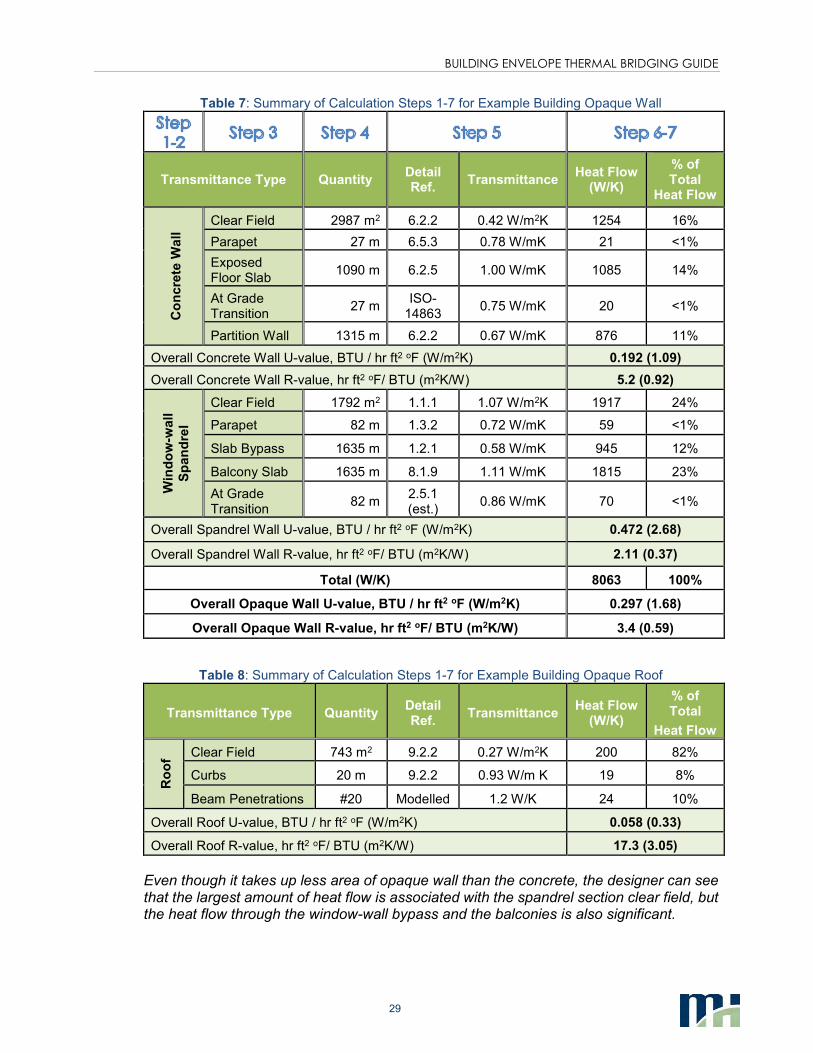
The designer calculates the overall U-values for each construction type, along with an overall Opaque Wall U-value and Opaque Roof U-value separately. The summary of all steps for the example building is given in Table 7 and 8 for the walls and roof respectively.
BUILDING ENVELOPE THERMAL BRIDGING GUIDE
29
Table 7: Summary of Calculation Steps 1-7 for Example Building Opaque Wall
Transmittance Type Quantity Detail Ref.
Transmittance Heat Flow
(W/K)
% of Total
Heat Flow
Co
ncre
te W
all
Clear Field 2987 m2 6.2.2 0.42 W/m2K 1254 16%
Parapet 27 m 6.5.3 0.78 W/mK 21 <1%
Exposed Floor Slab
1090 m 6.2.5 1.00 W/mK 1085 14%
At Grade Transition
27 m ISO-
14863 0.75 W/mK 20 <1%
Partition Wall 1315 m 6.2.2 0.67 W/mK 876 11%
Overall Concrete Wall U-value, BTU / hr ft2 oF (W/m2K) 0.192 (1.09)
Overall Concrete Wall R-value, hr ft2 oF/ BTU (m2K/W) 5.2 (0.92)
Win
do
w-w
all
Sp
an
dre
l
Clear Field 1792 m2 1.1.1 1.07 W/m2K 1917 24%
Parapet 82 m 1.3.2 0.72 W/mK 59 <1%
Slab Bypass 1635 m 1.2.1 0.58 W/mK 945 12%
Balcony Slab 1635 m 8.1.9 1.11 W/mK 1815 23%
At Grade Transition
82 m 2.5.1 (est.)
0.86 W/mK 70 <1%
Overall Spandrel Wall U-value, BTU / hr ft2 oF (W/m2K) 0.472 (2.68)
Overall Spandrel Wall R-value, hr ft2 oF/ BTU (m2K/W) 2.11 (0.37)
Total (W/K) 8063 100%
Overall Opaque Wall U-value, BTU / hr ft2 oF (W/m2K) 0.297 (1.68)
Overall Opaque Wall R-value, hr ft2 oF/ BTU (m2K/W) 3.4 (0.59)
Table 8: Summary of Calculation Steps 1-7 for Example Building Opaque Roof
Transmittance Type Quantity Detail Ref.
Transmittance Heat Flow
(W/K)
% of Total
Heat Flow
Ro
of
Clear Field 743 m2 9.2.2 0.27 W/m2K 200 82%
Curbs 20 m 9.2.2 0.93 W/m K 19 8%
Beam Penetrations #20 Modelled 1.2 W/K 24 10%
Overall Roof U-value, BTU / hr ft2 oF (W/m2K) 0.058 (0.33)
Overall Roof R-value, hr ft2 oF/ BTU (m2K/W) 17.3 (3.05)
Even though it takes up less area of opaque wall than the concrete, the designer can see that the largest amount of heat flow is associated with the spandrel section clear field, but the heat flow through the window-wall bypass and the balconies is also significant.
BUILDING ENVELOPE THERMAL BRIDGING GUIDE
30
6. INPUTTING THERMAL VALUES INTO ENERGY MODELS
Determining overall building performance, including the combined interaction between envelope, mechanical and electrical systems, is often termed “whole building energy analysis” and is often assessed using computer simulation and is used for multiple purposes, including:
• Design decision making through parametric analysis, by considering the energy and cost impact of design decisions to reduce energy or meet code
• Demonstrating compliance with energy codes
• Comparing a proposed building to a reference building for green building rating systems (LEED, Green Globes, etc.)
• Estimating energy use in new or existing buildings
• Estimating the impact of operational improvements or capital investments in existing buildings
• Heat loss calculations for mechanical system sizing
One of the main drivers for creating this guide was to provide more accurate thermal values and a methodology for designers to assist in creating more precise energy models.
Currently, there are few energy modeling programs that allow linear transmittance values to be input directly into energy simulations. While this feature is being considered for development for common building energy simulation software, at the moment this ability is not widely available. Thermal transmittances are either directly inputted as wall, roof or floor U-values or determined by using construction layers to build up the building envelope assemblies. For either case, the overall U-value that includes the effects of linear and points transmittances must first be determined without the assistance of the energy modeling software to ensure that the correct thermal transmittances will be processed by the model.
It is important to emphasize that air leakage and dynamic thermal responses are accounted for by separate functions in typical whole building energy models. Thermal bridging is accounted for only in the thermal transmittances that are processed by the energy model. See Appendix C for an explanation of how energy models take into account thermal mass separately from thermal transmittances.
Many modeling programs use construction layers to build up the building envelope assemblies based on material properties. To account for thermal bridging, all the material properties should be left as is, while only the insulating layer R-value should be de-rated such that the correct overall U-value determined from calculation is matched and output by the software. This method allows for the functions that account for thermal mass to be approximated by the software.
Example: a section of concrete wall with R-15 exterior insulation contains a balcony slab and is calculated to have an overall U-value of U-0.16. The energy modeling program being used requires construction layers as the inputs. The layers are input with default values for the air films, cladding, airspaces, concrete and interior finishes and the simulation output shows a U-value of U-0.05. The exterior insulation R-value is edited

BUILDING ENVELOPE THERMAL BRIDGING GUIDE
31
and decreased from R-15 such that in the simulation output, the U-value for the overall wall assembly matches U-0.16.
One final note on model inputs, the clear field U-values given in the thermal performance catalogue in this guide are based on the ASHRAE 1365-RP methodology, which include air films. Many energy modeling programs calculate air films separately. The air films for the modeled details in this guide are listed with the material properties in each of the details in Appendix A. The thermal resistance of these air films may need to be subtracted out before entering R- or U-values into an energy modeling program.
BUILDING ENVELOPE THERMAL BRIDGING GUIDE
32
7. REFERENCES
ASHRAE. (2010). ASHRAE 90.1 Energy Standard for Buildings Except Low-Rise Residential
Buildings. Atlanta, GA: American Society of Heating, Rerigerating and Air-Conditioning
Engineers Inc.
ASHRAE. (2013). Handbook of Fundamentals. Atlanta, GA: American Society of Heating,
Refrigerating and Air-Conditioning Engineers Inc.
CEN. (2007). ISO 14683 Thermal bridges in building construction - Linear thermal transmittance
- Simplified methods and default values. Brussels: European Committee for
Standardization.
Janssens, A., Van Londersele, E., Vandermarcke, B., Roels, S., Standaert, P., Wouters, P., &
A, A. (2007). Developement of Limits for the Linear Thermal Transmittances of Thermal
Bridges in Buildings. Thermal Performance of the Exterior Envelopes of Whole Buildings
X International Conference (p. Paper 182). Atlanta, GA: American Society of Heating,
Refrigerating and Air-Conditioning Engineers.
Mitchell, R., Kohler, C., Curcija, D., Zhu, L., Vidanovic, S., Czarnecki, S., . . . Huizenga, C. (Rev
2013). THERM 6.3/WINDOW 6.3 NFRC Simulation Manual. Berkeley: University of
California.
Morrison Hershfield Limited. (2011). ASHRAE 1365-RP Thermal Performance of Building
Envelope Construction Details for Mid- and High-Rise Buildings. Atlanta, GA: American
Society of Heating, Refrigerations and Air-Conditioning Engineers Inc.
Recommended