1
CC-Link Partner Association
CC-Link Intelligent Device Driver
1 System Configuration....................................................................................................... 4
2 Selection of External Device .......................................................................................... 11
3 Example of Communication Setting ............................................................................... 12
4 Setup Items .................................................................................................................... 25
5 Cable Diagram ............................................................................................................... 29
6 Supported Devices......................................................................................................... 31
7 Device Code and Address Code.................................................................................... 35
8 Error Messages.............................................................................................................. 37
CC-Link Intelligent Device Driver
GP-Pro EX Device/PLC Connection Manual 2
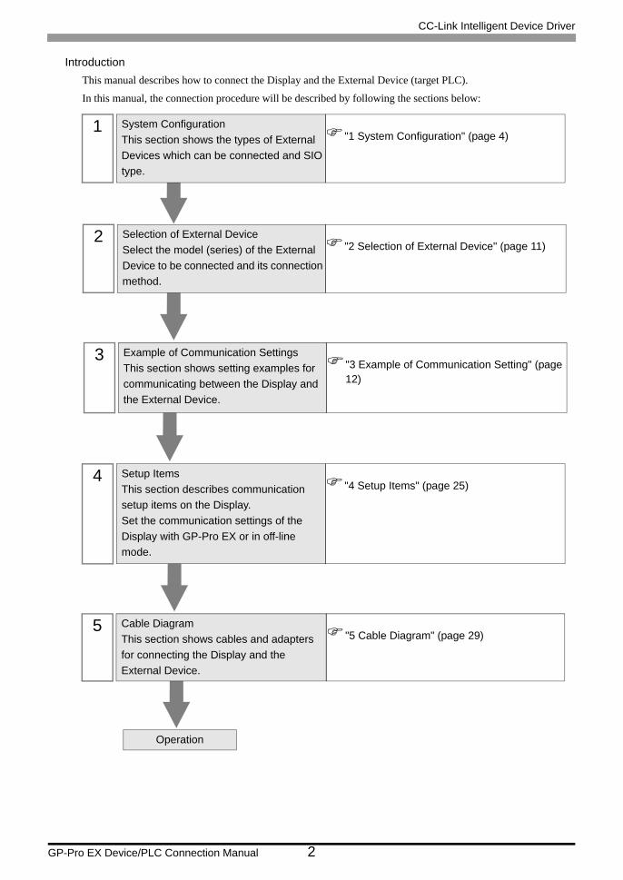
IntroductionThis manual describes how to connect the Display and the External Device (target PLC).
In this manual, the connection procedure will be described by following the sections below:
1 System ConfigurationThis section shows the types of External Devices which can be connected and SIO type.
"1 System Configuration" (page 4)
2 Selection of External DeviceSelect the model (series) of the External Device to be connected and its connection method.
"2 Selection of External Device" (page 11)
3 Example of Communication SettingsThis section shows setting examples for communicating between the Display and the External Device.
"3 Example of Communication Setting" (page 12)
4 Setup ItemsThis section describes communication setup items on the Display.Set the communication settings of the Display with GP-Pro EX or in off-line mode.
"4 Setup Items" (page 25)
Operation
5 Cable DiagramThis section shows cables and adapters for connecting the Display and the External Device.
"5 Cable Diagram" (page 29)
CC-Link Intelligent Device Driver
GP-Pro EX Device/PLC Connection Manual 3
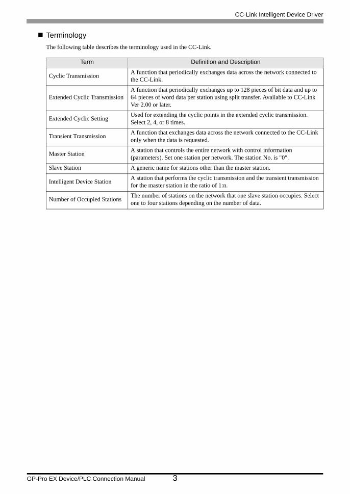
TerminologyThe following table describes the terminology used in the CC-Link.
Term Definition and Description
Cyclic Transmission A function that periodically exchanges data across the network connected to the CC-Link.
Extended Cyclic TransmissionA function that periodically exchanges up to 128 pieces of bit data and up to 64 pieces of word data per station using split transfer. Available to CC-Link Ver 2.00 or later.
Extended Cyclic Setting Used for extending the cyclic points in the extended cyclic transmission. Select 2, 4, or 8 times.
Transient Transmission A function that exchanges data across the network connected to the CC-Link only when the data is requested.
Master Station A station that controls the entire network with control information (parameters). Set one station per network. The station No. is "0".
Slave Station A generic name for stations other than the master station.
Intelligent Device Station A station that performs the cyclic transmission and the transient transmission for the master station in the ratio of 1:n.
Number of Occupied Stations The number of stations on the network that one slave station occupies. Select one to four stations depending on the number of data.
CC-Link Intelligent Device Driver
GP-Pro EX Device/PLC Connection Manual 4
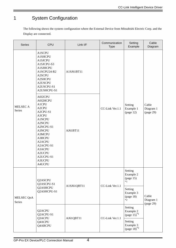
1 System Configuration
The following shows the system configuration where the External Device from Mitsubishi Electric Corp. and the
Display are connected.
Series CPU Link I/F Communication Type
Setting Example
Cable Diagram
MELSEC ASeries
A1SCPUA1SHCPUA1SJCPUA1SJCPU-S3A1SJHCPUA1SCPU24-R2A2SCPUA2SHCPUA2USCPUA2USCPU-S1A2USHCPU-S1
A1SJ61BT11
CC-Link Ver.1.1Setting Example 1 (page 12)
Cable Diagram 1 (page 29)
A0J2CPUA0J2HCPUA1CPUA2CPUA2CPU-S1A3CPUA1NCPUA2NCPUA2NCPU-S1A3NCPUA3MCPUA3HCPUA2ACPUA2ACPU-S1A3ACPUA2UCPUA2UCPU-S1A3UCPUA4UCPU
AJ61BT11
MELSEC QnASeries
Q2ASCPUQ2ASCPU-S1Q2ASHCPUQ2ASHCPU-S1
A1SJ61QBT11 CC-Link Ver.1.1
Setting Example 2 (page 15)*1
Cable Diagram 1 (page 29)
Setting Example 3 (page 18)*2
Q2ACPUQ2ACPU-S1Q3ACPUQ4ACPUQ4ARCPU
AJ61QBT11 CC-Link Ver.1.1
Setting Example 2 (page 15)*1
Setting Example 3 (page 18)*2
CC-Link Intelligent Device Driver
GP-Pro EX Device/PLC Connection Manual 5
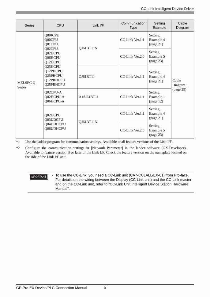
MELSEC QSeries
Q00JCPUQ00CPUQ01CPUQ02CPUQ02HCPUQ06HCPUQ12HCPUQ25HCPUQ12PHCPUQ25PHCPUQ12PRHCPUQ25PRHCPU
QJ61BT11N
CC-Link Ver.1.1Setting Example 4 (page 21)
Cable Diagram 1 (page 29)
CC-Link Ver.2.0Setting Example 5 (page 23)
QJ61BT11 CC-Link Ver.1.1Setting Example 4 (page 21)
Q02CPU-AQ02HCPU-AQ06HCPU-A
A1SJ61BT11 CC-Link Ver.1.1Setting Example 1 (page 12)
Q02UCPUQ03UDCPUQ04UDHCPUQ06UDHCPU
QJ61BT11N
CC-Link Ver.1.1Setting Example 4 (page 21)
CC-Link Ver.2.0Setting Example 5 (page 23)
*1 Use the ladder program for communication settings. Available to all feature versions of the Link I/F.
*2 Configure the communication settings in [Network Parameter] in the ladder software (GX-Developer).Available to feature version B or later of the Link I/F. Check the feature version on the nameplate located onthe side of the Link I/F unit.
• To use the CC-Link, you need a CC-Link unit (CA7-CCLALL/EX-01) from Pro-face. For details on the wiring between the Display (CC-Link unit) and the CC-Link master and on the CC-Link unit, refer to "CC-Link Unit Intelligent Device Station Hardware Manual".
Series CPU Link I/F Communication Type
Setting Example
Cable Diagram
CC-Link Intelligent Device Driver
GP-Pro EX Device/PLC Connection Manual 6
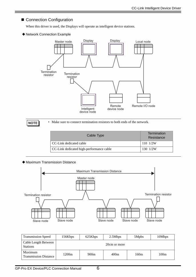
Connection ConfigurationWhen this driver is used, the Displays will operate as intelligent device stations.
Network Connection Example
Maximum Transmission Distance
• Make sure to connect termination resistors to both ends of the network.
Transmission Speed 156Kbps 625Kbps 2.5Mbps 5Mpbs 10Mbps
Cable Length Between Stations 20cm or more
Maximum Transmission Distance 1200m 900m 400m 160m 100m
DisplayMaster node Display
Terminationresistor
Remote I/O nodeIntelligent
device node
Remotedevice node
Local node
Terminationresistor
Cable Type Termination Resistance
CC-Link dedicated cable 110 1/2W
CC-Link dedicated high-performance cable 130 1/2W
Master node
Termination resistorTermination resistor
Slave nodeSlave node Slave nodeSlave nodeSlave node
Maximum Transmission Distance
CC-Link Intelligent Device Driver
GP-Pro EX Device/PLC Connection Manual 7
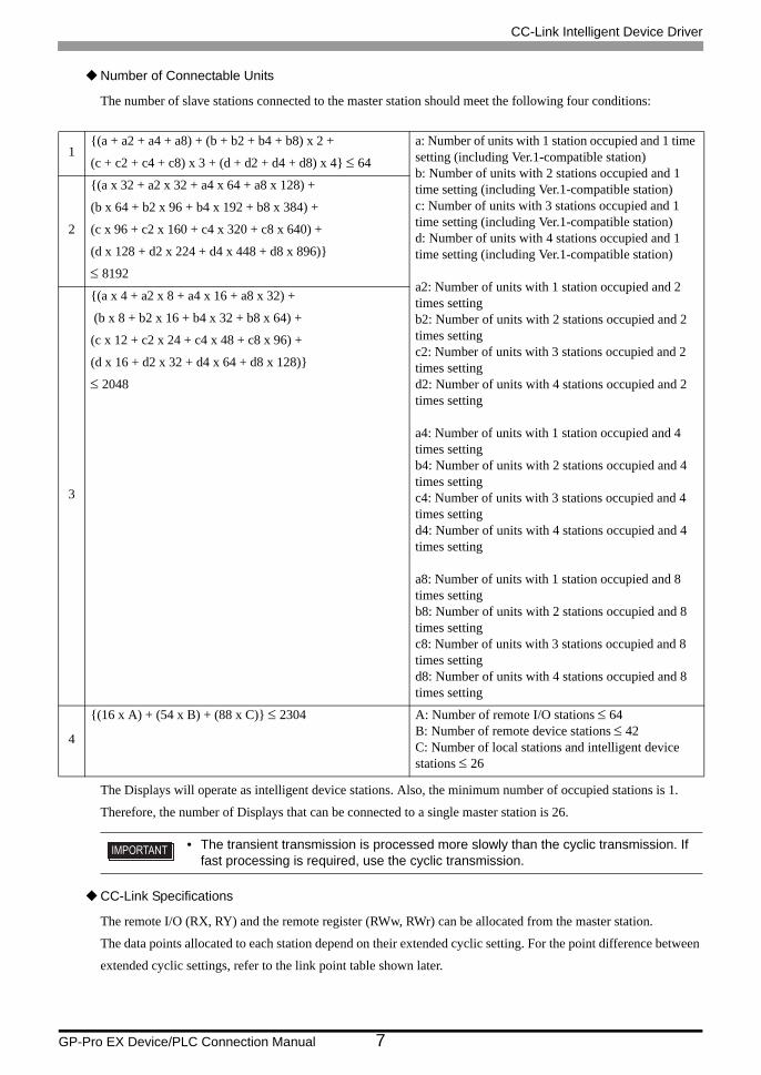
Number of Connectable Units
The number of slave stations connected to the master station should meet the following four conditions:
The Displays will operate as intelligent device stations. Also, the minimum number of occupied stations is 1.
Therefore, the number of Displays that can be connected to a single master station is 26.
CC-Link Specifications
The remote I/O (RX, RY) and the remote register (RWw, RWr) can be allocated from the master station.
The data points allocated to each station depend on their extended cyclic setting. For the point difference between
extended cyclic settings, refer to the link point table shown later.
1{(a + a2 + a4 + a8) + (b + b2 + b4 + b8) x 2 +
(c + c2 + c4 + c8) x 3 + (d + d2 + d4 + d8) x 4} ≤ 64
a: Number of units with 1 station occupied and 1 time setting (including Ver.1-compatible station)b: Number of units with 2 stations occupied and 1 time setting (including Ver.1-compatible station)c: Number of units with 3 stations occupied and 1 time setting (including Ver.1-compatible station)d: Number of units with 4 stations occupied and 1 time setting (including Ver.1-compatible station)
a2: Number of units with 1 station occupied and 2 times settingb2: Number of units with 2 stations occupied and 2 times settingc2: Number of units with 3 stations occupied and 2 times settingd2: Number of units with 4 stations occupied and 2 times setting
a4: Number of units with 1 station occupied and 4 times settingb4: Number of units with 2 stations occupied and 4 times settingc4: Number of units with 3 stations occupied and 4 times settingd4: Number of units with 4 stations occupied and 4 times setting
a8: Number of units with 1 station occupied and 8 times settingb8: Number of units with 2 stations occupied and 8 times settingc8: Number of units with 3 stations occupied and 8 times settingd8: Number of units with 4 stations occupied and 8 times setting
2
{(a x 32 + a2 x 32 + a4 x 64 + a8 x 128) +
(b x 64 + b2 x 96 + b4 x 192 + b8 x 384) +
(c x 96 + c2 x 160 + c4 x 320 + c8 x 640) +
(d x 128 + d2 x 224 + d4 x 448 + d8 x 896)}
≤ 8192
3
{(a x 4 + a2 x 8 + a4 x 16 + a8 x 32) +
(b x 8 + b2 x 16 + b4 x 32 + b8 x 64) +
(c x 12 + c2 x 24 + c4 x 48 + c8 x 96) +
(d x 16 + d2 x 32 + d4 x 64 + d8 x 128)}
≤ 2048
4
{(16 x A) + (54 x B) + (88 x C)} ≤ 2304 A: Number of remote I/O stations ≤ 64B: Number of remote device stations ≤ 42C: Number of local stations and intelligent device stations ≤ 26
• The transient transmission is processed more slowly than the cyclic transmission. If fast processing is required, use the cyclic transmission.
CC-Link Intelligent Device Driver
GP-Pro EX Device/PLC Connection Manual 8
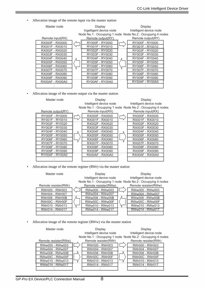
• Allocation image of the remote input via the master station
• Allocation image of the remote output via the master station
• Allocation image of the remote register (RWr) via the master station
• Allocation image of the remote register (RWw) via the master station
Master node
Remote input(RX)
RX000F - RX0000
RX001F - RX0010
RX002F - RX0020
RX003F - RX0030
RX004F - RX0040
RX005F - RX0050
RX006F - RX0060
RX007F - RX0070
RX008F - RX0080
RX009F - RX0090
RX00AF - RX00A0
:
Display
Ingelligent device node
Node No.1 : Occupying 1 node
Remote output(RY)
RY000F - RY0000
RY001F - RY0010
RY002F - RY0020
RY003F - RY0030
RY004F - RY0040
RY005F - RY0050
RY006F - RY0060
RY007F - RY0070
RY008F - RY0080
RY009F - RY0090
RY00AF - RY00A0
:
Display
Intelligent device node
Node No.2 : Occupying 4 nodes
Remote output(RY)
RY000F - RY0000
RY001F - RY0010
RY002F - RY0020
RY003F - RY0030
RY004F - RY0040
RY005F - RY0050
RY006F - RY0060
RY007F - RY0070
RY008F - RY0080
RY009F - RY0090
RY00AF - RY00A0
:
Master node
Remote output(RY)
RY000F - RY0000
RY001F - RY0010
RY002F - RY0020
RY003F - RY0030
RY004F - RY0040
RY005F - RY0050
RY006F - RY0060
RY007F - RY0070
RY008F - RY0080
RY009F - RY0090
RY00AF - RY00A0
:
Display
Intelligent device node
Node No.1 : Occupying 1 node
Remote input(RX)
RX000F - RX0000
RX001F - RX0010
RX002F - RX0020
RX003F - RX0030
RX004F - RX0040
RX005F - RX0050
RX006F - RX0060
RX007F - RX0070
RX008F - RX0080
RX009F - RX0090
RX00AF - RX00A0
:
Display
Intelligent device node
Node No.2 : Occupying 4 nodes
Remote input(RX)
RX000F - RX0000
RX001F - RX0010
RX002F - RX0020
RX003F - RX0030
RX004F - RX0040
RX005F - RX0050
RX006F - RX0060
RX007F - RX0070
RX008F - RX0080
RX009F - RX0090
RX00AF - RX00A0
:
Master node
Remote resister(RWr)
RWr000 - RWr003
RWr004 - RWr007
RWr008 - RWr00B
RWr00C - RWr00F
RWr010 - RWr013
RWr014 - RWr017
:
Display
Intelligent device node
Node No.1 : Occupying 1 node
Remote resister(RWw)
RWw000 - RWw003
RWw004 - RWw007
RWw008 - RWw00B
RWw00C - RWw00F
RWw010 - RWw013
RWw014 - RWw017
:
Display
Intelligent device node
Node No.2 : Occupying 4 nodes
Remote resister(RWw)
RWw000 - RWw003
RWw004 - RWw007
RWw008 - RWw00B
RWw00C - RWw00F
RWw010 - RWw013
RWw014 - RWw017
:
Master node
Remote resister(RWw)
RWw000 - RWw003
RWw004 - RWw007
RWw008 - RWw00B
RWw00C - RWw00F
RWw010 - RWw013
RWw014 - RWw017
:
Display
Intelligent device node
Node No.1 : Occupying 1 node
Remote resister(RWr)
RWr000 - RWr003
RWr004 - RWr007
RWr008 - RWr00B
RWr00C - RWr00F
RWr010 - RWr013
RWr014 - RWr017
:
Display
Intelligent device node
Node No.2 : Occupying 4 nodes
Remote resister(RWr)
RWr000 - RWr003
RWr004 - RWr007
RWr008 - RWr00B
RWr00C - RWr00F
RWr010 - RWr013
RWr014 - RWr017
:
CC-Link Intelligent Device Driver
GP-Pro EX Device/PLC Connection Manual 9
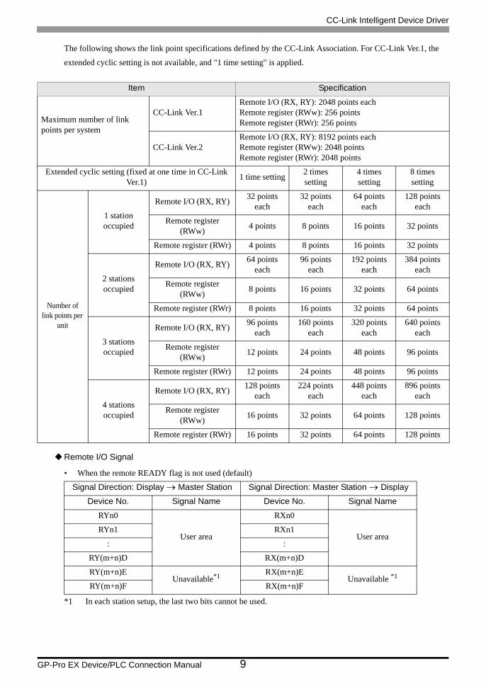
The following shows the link point specifications defined by the CC-Link Association. For CC-Link Ver.1, the
extended cyclic setting is not available, and "1 time setting" is applied.
Remote I/O Signal
• When the remote READY flag is not used (default)
Item Specification
Maximum number of link points per system
CC-Link Ver.1Remote I/O (RX, RY): 2048 points eachRemote register (RWw): 256 pointsRemote register (RWr): 256 points
CC-Link Ver.2Remote I/O (RX, RY): 8192 points eachRemote register (RWw): 2048 pointsRemote register (RWr): 2048 points
Extended cyclic setting (fixed at one time in CC-Link Ver.1) 1 time setting 2 times
setting4 times setting
8 times setting
Number of link points per
unit
1 station occupied
Remote I/O (RX, RY) 32 points each
32 points each
64 points each
128 points each
Remote register (RWw) 4 points 8 points 16 points 32 points
Remote register (RWr) 4 points 8 points 16 points 32 points
2 stations occupied
Remote I/O (RX, RY) 64 points each
96 points each
192 points each
384 points each
Remote register (RWw) 8 points 16 points 32 points 64 points
Remote register (RWr) 8 points 16 points 32 points 64 points
3 stations occupied
Remote I/O (RX, RY) 96 points each
160 points each
320 points each
640 points each
Remote register (RWw) 12 points 24 points 48 points 96 points
Remote register (RWr) 12 points 24 points 48 points 96 points
4 stations occupied
Remote I/O (RX, RY) 128 points each
224 points each
448 points each
896 points each
Remote register (RWw) 16 points 32 points 64 points 128 points
Remote register (RWr) 16 points 32 points 64 points 128 points
Signal Direction: Display → Master Station Signal Direction: Master Station → Display
Device No. Signal Name Device No. Signal Name
RYn0
User area
RXn0
User areaRYn1 RXn1
: :
RY(m+n)D RX(m+n)D
RY(m+n)EUnavailable*1
*1 In each station setup, the last two bits cannot be used.
RX(m+n)EUnavailable *1
RY(m+n)F RX(m+n)F
CC-Link Intelligent Device Driver
GP-Pro EX Device/PLC Connection Manual 10
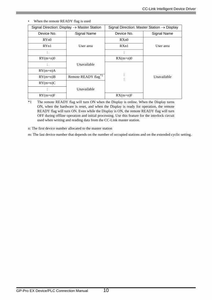
• When the remote READY flag is used
n: The first device number allocated to the master station
m: The last device number that depends on the number of occupied stations and on the extended cyclic setting.
Signal Direction: Display → Master Station Signal Direction: Master Station → Display
Device No. Signal Name Device No. Signal Name
RYn0
User area
RXn0
User areaRYn1 RXn1
: :
RY(m+n)0
Unavailable
RX(m+n)0
Unavailable
:
::
RY(m+n)A
RY(m+n)B Remote READY flag*1
*1 The remote READY flag will turn ON when the Display is online. When the Display turnsON, when the hardware is reset, and when the Display is ready for operation, the remoteREADY flag will turn ON. Even while the Display is ON, the remote READY flag will turnOFF during offline operation and initial processing. Use this feature for the interlock circuitused when writing and reading data from the CC-Link master station.
RY(m+n)C
Unavailable:
RY(m+n)F RX(m+n)F
CC-Link Intelligent Device Driver
GP-Pro EX Device/PLC Connection Manual 11
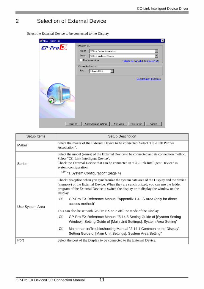
2 Selection of External Device
Select the External Device to be connected to the Display.
Setup Items Setup Description
Maker Select the maker of the External Device to be connected. Select "CC-Link Partner Association".
Series
Select the model (series) of the External Device to be connected and its connection method. Select "CC-Link Intelligent Device".Check the External Device that can be connected in "CC-Link Intelligent Device" in system configuration.
"1 System Configuration" (page 4)
Use System Area
Check this option when you synchronize the system data area of the Display and the device (memory) of the External Device. When they are synchronized, you can use the ladder program of the External Device to switch the display or to display the window on the Display.
Cf. GP-Pro EX Reference Manual "Appendix 1.4 LS Area (only for direct access method)"
This can also be set with GP-Pro EX or in off-line mode of the Display.
Cf. GP-Pro EX Reference Manual "5.14.6 Setting Guide of [System Setting Window], Setting Guide of [Main Unit Settings], System Area Setting"
Cf. Maintenance/Troubleshooting Manual "2.14.1 Common to the Display", Setting Guide of [Main Unit Settings], System Area Setting"
Port Select the port of the Display to be connected to the External Device.
CC-Link Intelligent Device Driver
GP-Pro EX Device/PLC Connection Manual 12
3 Example of Communication Setting
The following shows examples of communication settings of the Display and the External Device, which are
recommended by Pro-face.
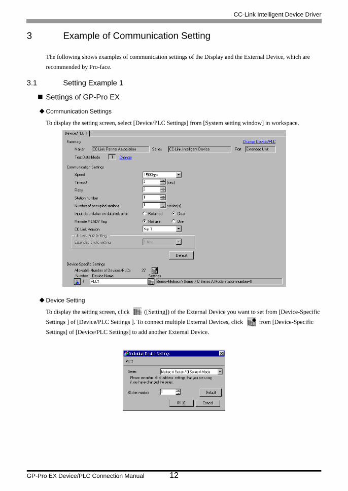
3.1 Setting Example 1
Settings of GP-Pro EX
Communication Settings
To display the setting screen, select [Device/PLC Settings] from [System setting window] in workspace.
Device Setting
To display the setting screen, click ([Setting]) of the External Device you want to set from [Device-Specific
Settings ] of [Device/PLC Settings ]. To connect multiple External Devices, click from [Device-Specific
Settings] of [Device/PLC Settings] to add another External Device.

CC-Link Intelligent Device Driver
GP-Pro EX Device/PLC Connection Manual 13
Settings of External DeviceTo configure communication settings, use the DIP switches and rotary switches on the External Device, and the
ladder software (GX-Developer). After completing the settings, reboot the External Device to enable them. Please
refer to the manual of the External Device for details.
DIP Switch
Station Setting Rotary Switch
Mode Setting Rotary Switch
Baud Rate Setting Rotary Switch
DIP Switch Settings Setup DescriptionSW1 OFF Number of occupied stations (OFF: Master station ON: Local station)SW2 OFF Always OFFSW3 OFF Always OFFSW4 OFF Data status of data link error station (OFF: Clear ON: Retained)
SW5 OFF Number of occupied stations (OFF: 1 station occupied ON: 4 stations occupied)
SW6 OFF Always OFFSW7 OFF Always OFFSW8 OFF Always OFF
Rotary Switch Settings Setup Descriptionx 10 0 Station No. of the External Device (tens digit)x 1 0 Station No. of the External Device (ones digit)
• Always assign "00" to the master station, and the station No. to the local station.
Rotary Switch Settings Setup DescriptionMODE 0 Online
Rotary Switch Settings Setup DescriptionB RATE 0 156Kbps

CC-Link Intelligent Device Driver
GP-Pro EX Device/PLC Connection Manual 14
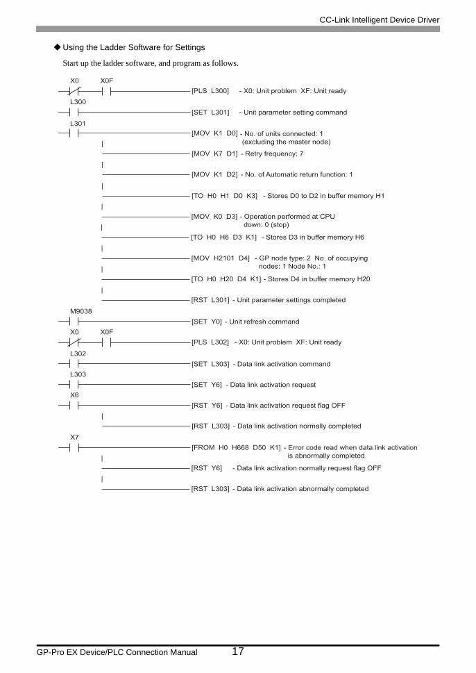
Using the Ladder Software for Settings
Start up the ladder software, and program as follows.
X0 X0F
[PLS L300]
L300
[SET L301]
L301
[MOV K1 D0]
|
[MOV K7 D1]
|
[TO H0 H1 D0 K3]
|
[MOV K0 D3]
|
[TO H0 H6 D3 K1]
|
[MOV H2101 D4]
|
[TO H0 H20 D4 K1]
|
[RST L301]
- X0: Unit problem XF: Unit ready
- Unit parameter setting command
- No. of units connected: 1
(excluding the master node)
- Retry frequency: 7
- Stores D0 to D2 in buffer memory H1
- Operation performed at CPU
down: 0 (stop)
|
[MOV K1 D2] - No. of Automatic return function: 1
- Stores D3 in buffer memory H6
- GP node type: 2 No. of occupying
nodes: 1 Node No.: 1
- Stores D4 in buffer memory H20
- Unit parameter settings completed
M9038
[SET Y0] - Unit refresh command
X0 X0F
[PLS L302] - X0: Unit problem XF: Unit ready
L302
[SET L303] - Data link activation command
L303
[SET Y6] - Data link activation request
X6
[RST Y6] - Data link activation request flag OFF
|
[RST L303] - Data link activation normally completed
X7
[FROM H0 H668 D50 K1] - Error code read when data link activation
is abnormally completed|
[RST Y6] - Data link activation normally request flag OFF
|
[RST L303] - Data link activation abnormally completed

CC-Link Intelligent Device Driver
GP-Pro EX Device/PLC Connection Manual 15
3.2 Setting Example 2
Settings of GP-Pro EX
Communication Settings
To display the setting screen, select [Device/PLC Settings] from [System setting window] in workspace.
Device Setting
To display the setting screen, click ([Setting]) of the External Device you want to set from [Device-Specific
Settings ] of [Device/PLC Settings ]. To connect multiple External Devices, click from [Device-Specific
Settings] of [Device/PLC Settings] to add another External Device.

CC-Link Intelligent Device Driver
GP-Pro EX Device/PLC Connection Manual 16
Settings of External DeviceTo configure communication settings, use the DIP switches and rotary switches on the External Device, and the
ladder software (GX-Developer). After completing the settings, reboot the External Device to enable them. Please
refer to the manual of the External Device for details.
DIP Switch
Station Setting Rotary Switch
Mode Setting Rotary Switch
Baud Rate Setting Rotary Switch
DIP Switch Settings Setup DescriptionSW1 OFF Number of occupied stations (OFF: Master station ON: Local station)SW2 OFF Always OFFSW3 OFF Always OFFSW4 OFF Data status of data link error station (OFF: Clear ON: Retained)
SW5 OFF Number of occupied stations (OFF: 1 station occupied ON: 4 stations occupied)
SW6 OFF Always OFFSW7 OFF Always OFFSW8 OFF Always OFF
Rotary Switch Settings Setup Descriptionx 10 0 Station No. of the External Device (tens digit)x 1 0 Station No. of the External Device (ones digit)
• Always assign "00" to the master station, and the station No. to the local station.
Rotary Switch Settings Setup DescriptionMODE 0 Online
Rotary Switch Settings Setup DescriptionB RATE 0 156Kbps
CC-Link Intelligent Device Driver
GP-Pro EX Device/PLC Connection Manual 17
Using the Ladder Software for Settings
Start up the ladder software, and program as follows.
X0 X0F
[PLS L300]
L300
[SET L301]
L301
[MOV K1 D0]
|
[MOV K7 D1]
|
[TO H0 H1 D0 K3]
|
[MOV K0 D3]
|
[TO H0 H6 D3 K1]
|
[MOV H2101 D4]
|
[TO H0 H20 D4 K1]
|
[RST L301]
- X0: Unit problem XF: Unit ready
- Unit parameter setting command
- No. of units connected: 1
(excluding the master node)
- Retry frequency: 7
- Stores D0 to D2 in buffer memory H1
- Operation performed at CPU
down: 0 (stop)
|
[MOV K1 D2] - No. of Automatic return function: 1
- Stores D3 in buffer memory H6
- GP node type: 2 No. of occupying
nodes: 1 Node No.: 1
- Stores D4 in buffer memory H20
- Unit parameter settings completed
M9038
[SET Y0] - Unit refresh command
X0 X0F
[PLS L302] - X0: Unit problem XF: Unit ready
L302
[SET L303] - Data link activation command
L303
[SET Y6] - Data link activation request
X6
[RST Y6] - Data link activation request flag OFF
|
[RST L303] - Data link activation normally completed
X7
[FROM H0 H668 D50 K1] - Error code read when data link activation
is abnormally completed|
[RST Y6] - Data link activation normally request flag OFF
|
[RST L303] - Data link activation abnormally completed
CC-Link Intelligent Device Driver
GP-Pro EX Device/PLC Connection Manual 18
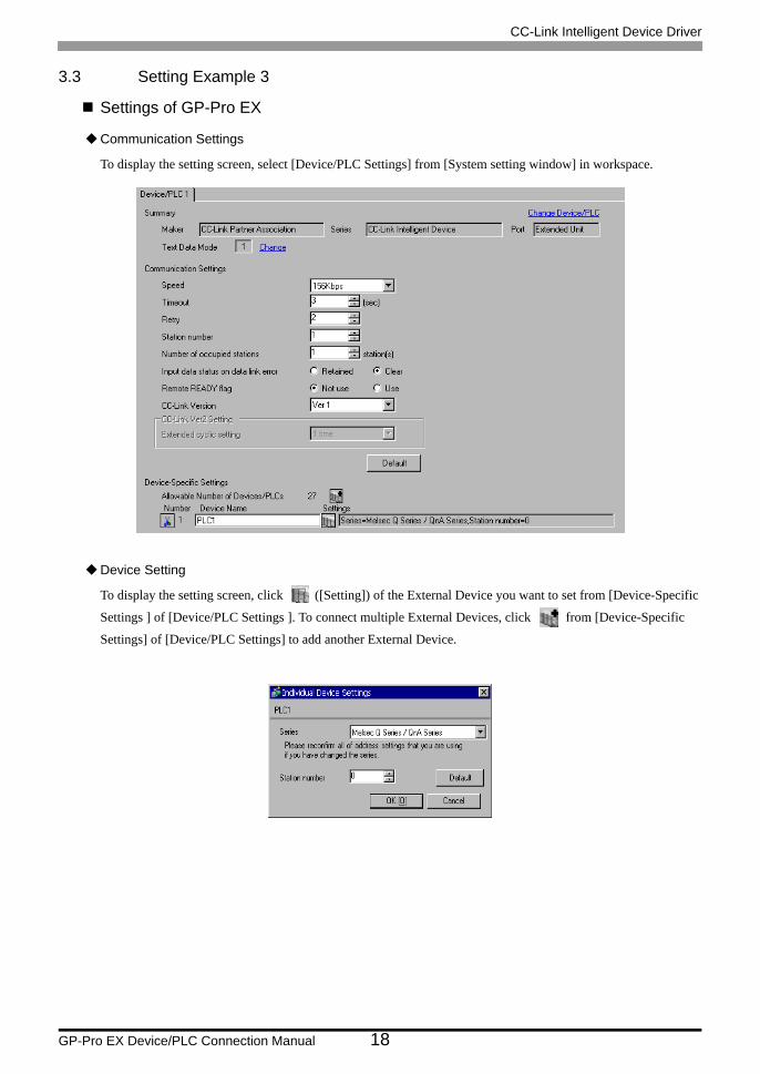
3.3 Setting Example 3
Settings of GP-Pro EX
Communication Settings
To display the setting screen, select [Device/PLC Settings] from [System setting window] in workspace.
Device Setting
To display the setting screen, click ([Setting]) of the External Device you want to set from [Device-Specific
Settings ] of [Device/PLC Settings ]. To connect multiple External Devices, click from [Device-Specific
Settings] of [Device/PLC Settings] to add another External Device.
CC-Link Intelligent Device Driver
GP-Pro EX Device/PLC Connection Manual 19
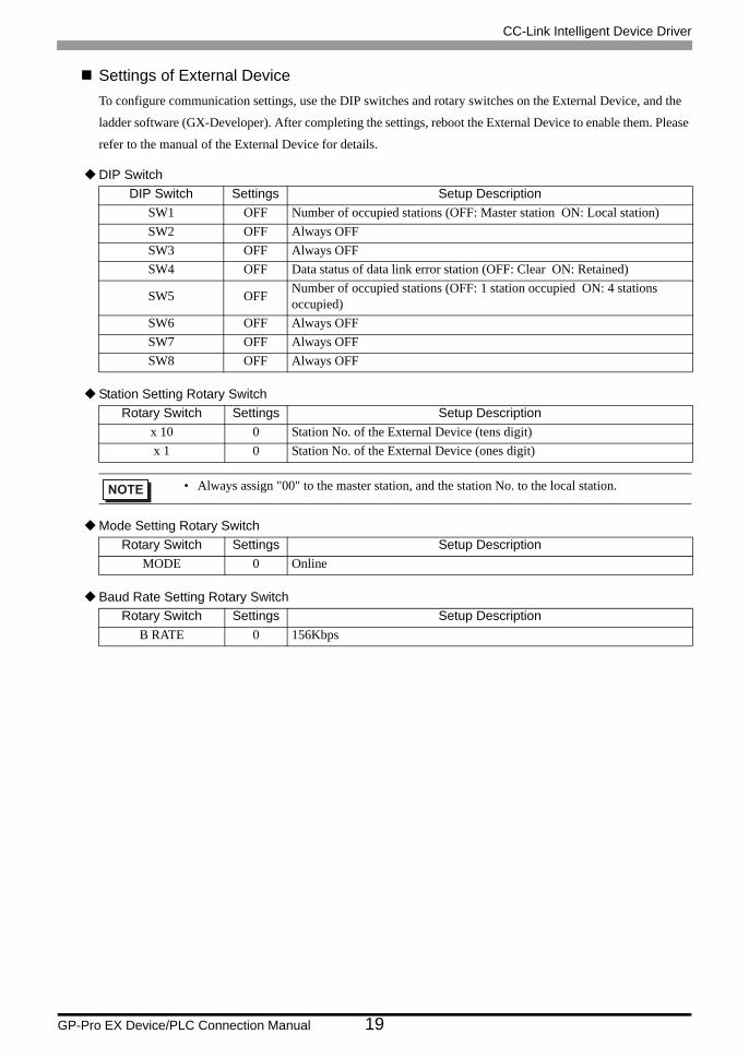
Settings of External DeviceTo configure communication settings, use the DIP switches and rotary switches on the External Device, and the
ladder software (GX-Developer). After completing the settings, reboot the External Device to enable them. Please
refer to the manual of the External Device for details.
DIP Switch
Station Setting Rotary Switch
Mode Setting Rotary Switch
Baud Rate Setting Rotary Switch
DIP Switch Settings Setup DescriptionSW1 OFF Number of occupied stations (OFF: Master station ON: Local station)SW2 OFF Always OFFSW3 OFF Always OFFSW4 OFF Data status of data link error station (OFF: Clear ON: Retained)
SW5 OFF Number of occupied stations (OFF: 1 station occupied ON: 4 stations occupied)
SW6 OFF Always OFFSW7 OFF Always OFFSW8 OFF Always OFF
Rotary Switch Settings Setup Descriptionx 10 0 Station No. of the External Device (tens digit)x 1 0 Station No. of the External Device (ones digit)
• Always assign "00" to the master station, and the station No. to the local station.
Rotary Switch Settings Setup DescriptionMODE 0 Online
Rotary Switch Settings Setup DescriptionB RATE 0 156Kbps
CC-Link Intelligent Device Driver
GP-Pro EX Device/PLC Connection Manual 20
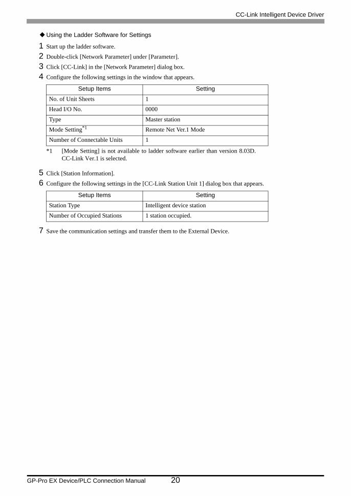
Using the Ladder Software for Settings
1 Start up the ladder software.
2 Double-click [Network Parameter] under [Parameter].
3 Click [CC-Link] in the [Network Parameter] dialog box.
4 Configure the following settings in the window that appears.
5 Click [Station Information].
6 Configure the following settings in the [CC-Link Station Unit 1] dialog box that appears.
7 Save the communication settings and transfer them to the External Device.
Setup Items Setting
No. of Unit Sheets 1
Head I/O No. 0000
Type Master station
Mode Setting*1
*1 [Mode Setting] is not available to ladder software earlier than version 8.03D.CC-Link Ver.1 is selected.
Remote Net Ver.1 Mode
Number of Connectable Units 1
Setup Items Setting
Station Type Intelligent device station
Number of Occupied Stations 1 station occupied.
CC-Link Intelligent Device Driver
GP-Pro EX Device/PLC Connection Manual 21
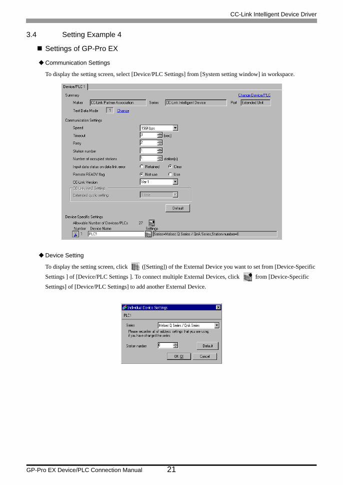
3.4 Setting Example 4
Settings of GP-Pro EX
Communication Settings
To display the setting screen, select [Device/PLC Settings] from [System setting window] in workspace.
Device Setting
To display the setting screen, click ([Setting]) of the External Device you want to set from [Device-Specific
Settings ] of [Device/PLC Settings ]. To connect multiple External Devices, click from [Device-Specific
Settings] of [Device/PLC Settings] to add another External Device.
CC-Link Intelligent Device Driver
GP-Pro EX Device/PLC Connection Manual 22
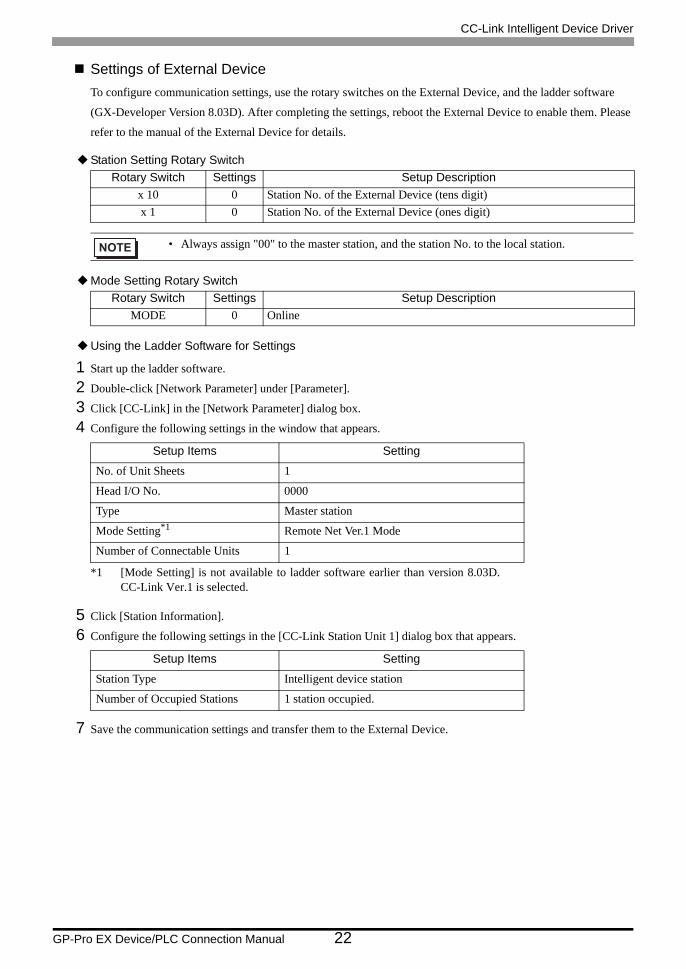
Settings of External DeviceTo configure communication settings, use the rotary switches on the External Device, and the ladder software
(GX-Developer Version 8.03D). After completing the settings, reboot the External Device to enable them. Please
refer to the manual of the External Device for details.
Station Setting Rotary Switch
Mode Setting Rotary Switch
Using the Ladder Software for Settings
1 Start up the ladder software.
2 Double-click [Network Parameter] under [Parameter].
3 Click [CC-Link] in the [Network Parameter] dialog box.
4 Configure the following settings in the window that appears.
5 Click [Station Information].
6 Configure the following settings in the [CC-Link Station Unit 1] dialog box that appears.
7 Save the communication settings and transfer them to the External Device.
Rotary Switch Settings Setup Descriptionx 10 0 Station No. of the External Device (tens digit)x 1 0 Station No. of the External Device (ones digit)
• Always assign "00" to the master station, and the station No. to the local station.
Rotary Switch Settings Setup DescriptionMODE 0 Online
Setup Items Setting
No. of Unit Sheets 1
Head I/O No. 0000
Type Master station
Mode Setting*1
*1 [Mode Setting] is not available to ladder software earlier than version 8.03D.CC-Link Ver.1 is selected.
Remote Net Ver.1 Mode
Number of Connectable Units 1
Setup Items Setting
Station Type Intelligent device station
Number of Occupied Stations 1 station occupied.
CC-Link Intelligent Device Driver
GP-Pro EX Device/PLC Connection Manual 23
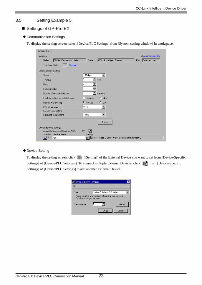
3.5 Setting Example 5
Settings of GP-Pro EX
Communication Settings
To display the setting screen, select [Device/PLC Settings] from [System setting window] in workspace.
Device Setting
To display the setting screen, click ([Setting]) of the External Device you want to set from [Device-Specific
Settings] of [Device/PLC Settings ]. To connect multiple External Devices, click from [Device-Specific
Settings] of [Device/PLC Settings] to add another External Device.
CC-Link Intelligent Device Driver
GP-Pro EX Device/PLC Connection Manual 24
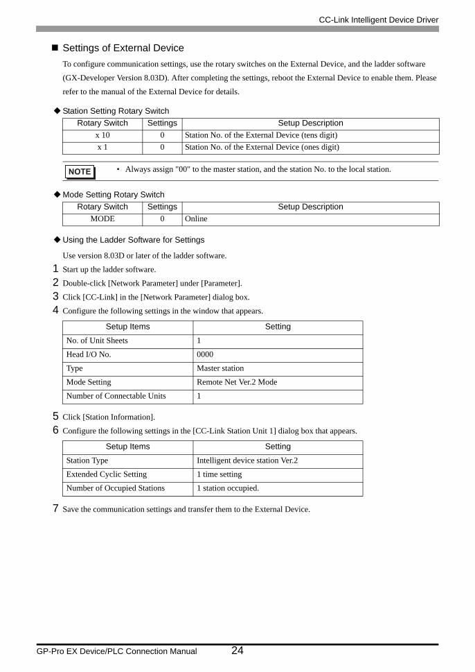
Settings of External DeviceTo configure communication settings, use the rotary switches on the External Device, and the ladder software
(GX-Developer Version 8.03D). After completing the settings, reboot the External Device to enable them. Please
refer to the manual of the External Device for details.
Station Setting Rotary Switch
Mode Setting Rotary Switch
Using the Ladder Software for Settings
Use version 8.03D or later of the ladder software.
1 Start up the ladder software.
2 Double-click [Network Parameter] under [Parameter].
3 Click [CC-Link] in the [Network Parameter] dialog box.
4 Configure the following settings in the window that appears.
5 Click [Station Information].
6 Configure the following settings in the [CC-Link Station Unit 1] dialog box that appears.
7 Save the communication settings and transfer them to the External Device.
Rotary Switch Settings Setup Descriptionx 10 0 Station No. of the External Device (tens digit)x 1 0 Station No. of the External Device (ones digit)
• Always assign "00" to the master station, and the station No. to the local station.
Rotary Switch Settings Setup DescriptionMODE 0 Online
Setup Items Setting
No. of Unit Sheets 1
Head I/O No. 0000
Type Master station
Mode Setting Remote Net Ver.2 Mode
Number of Connectable Units 1
Setup Items Setting
Station Type Intelligent device station Ver.2
Extended Cyclic Setting 1 time setting
Number of Occupied Stations 1 station occupied.
CC-Link Intelligent Device Driver
GP-Pro EX Device/PLC Connection Manual 25
4 Setup Items
Set the communication settings of the Display with GP-Pro Ex or in off-line mode of the Display.
The setting of each parameter must be identical to that of the External Device.
"3 Example of Communication Setting" (page 12)
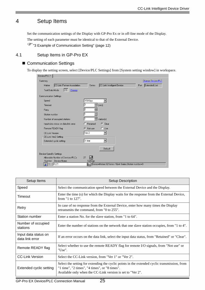
4.1 Setup Items in GP-Pro EX
Communication SettingsTo display the setting screen, select [Device/PLC Settings] from [System setting window] in workspace.
Setup Items Setup Description
Speed Select the communication speed between the External Device and the Display.
Timeout Enter the time (s) for which the Display waits for the response from the External Device, from "1 to 127".
Retry In case of no response from the External Device, enter how many times the Display retransmits the command, from "0 to 255".
Station number Enter a station No. for the slave station, from "1 to 64".
Number of occupied stations Enter the number of stations on the network that one slave station occupies, from "1 to 4".
Input data status on data link error If an error occurs on the data link, select the input data status, from "Retained" or "Clear".
Remote READY flag Select whether to use the remote READY flag for remote I/O signals, from "Not use" or "Use".
CC-Link Version Select the CC-Link version, from "Ver 1" or "Ver 2".
Extended cyclic settingSelect the setting for extending the cyclic points in the extended cyclic transmission, from "1 time", "2 times", "4 times", or "8 times".Available only when the CC-Link version is set to "Ver 2".
CC-Link Intelligent Device Driver
GP-Pro EX Device/PLC Connection Manual 26
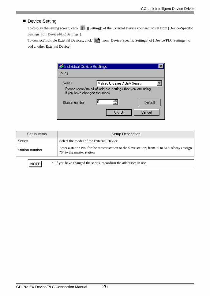
Device SettingTo display the setting screen, click ([Setting]) of the External Device you want to set from [Device-Specific
Settings ] of [Device/PLC Settings ].
To connect multiple External Devices, click from [Device-Specific Settings] of [Device/PLC Settings] to
add another External Device.
Setup Items Setup Description
Series Select the model of the External Device.
Station number Enter a station No. for the master station or the slave station, from "0 to 64". Always assign "0" to the master station.
• If you have changed the series, reconfirm the addresses in use.
CC-Link Intelligent Device Driver
GP-Pro EX Device/PLC Connection Manual 27
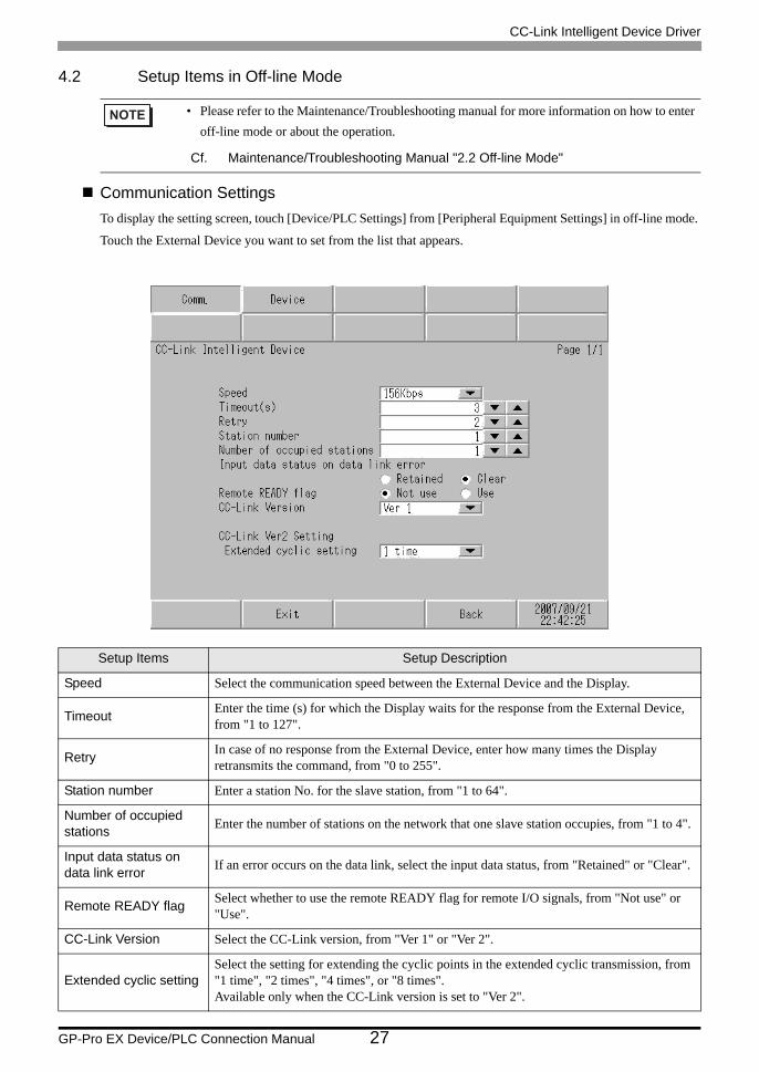
4.2 Setup Items in Off-line Mode
Communication SettingsTo display the setting screen, touch [Device/PLC Settings] from [Peripheral Equipment Settings] in off-line mode.
Touch the External Device you want to set from the list that appears.
• Please refer to the Maintenance/Troubleshooting manual for more information on how to enter off-line mode or about the operation.
Cf. Maintenance/Troubleshooting Manual "2.2 Off-line Mode"
Setup Items Setup Description
Speed Select the communication speed between the External Device and the Display.
Timeout Enter the time (s) for which the Display waits for the response from the External Device, from "1 to 127".
Retry In case of no response from the External Device, enter how many times the Display retransmits the command, from "0 to 255".
Station number Enter a station No. for the slave station, from "1 to 64".
Number of occupied stations Enter the number of stations on the network that one slave station occupies, from "1 to 4".
Input data status on data link error If an error occurs on the data link, select the input data status, from "Retained" or "Clear".
Remote READY flag Select whether to use the remote READY flag for remote I/O signals, from "Not use" or "Use".
CC-Link Version Select the CC-Link version, from "Ver 1" or "Ver 2".
Extended cyclic settingSelect the setting for extending the cyclic points in the extended cyclic transmission, from "1 time", "2 times", "4 times", or "8 times".Available only when the CC-Link version is set to "Ver 2".
CC-Link Intelligent Device Driver
GP-Pro EX Device/PLC Connection Manual 28
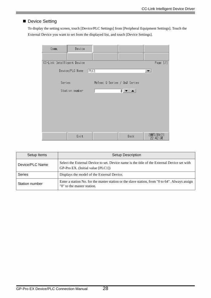
Device SettingTo display the setting screen, touch [Device/PLC Settings] from [Peripheral Equipment Settings]. Touch the
External Device you want to set from the displayed list, and touch [Device Settings].
Setup Items Setup Description
Device/PLC Name Select the External Device to set. Device name is the title of the External Device set with GP-Pro EX. (Initial value [PLC1])
Series Displays the model of the External Device.
Station number Enter a station No. for the master station or the slave station, from "0 to 64". Always assign "0" to the master station.
CC-Link Intelligent Device Driver
GP-Pro EX Device/PLC Connection Manual 29
5 Cable Diagram
The cable diagram shown below may differ from that recommended by the CC-Link Partner Association. Please
be assured, however, that there is no operational problem in applying the cable diagram shown in this manual.
• The FG pin on the External Device must be D-class grounded. Please refer to the manual of the External
Device for details.
• The SG and FG are connected inside the Display. If you connect the External Device to the SG, do not form
any short-circuit loop in the system design.
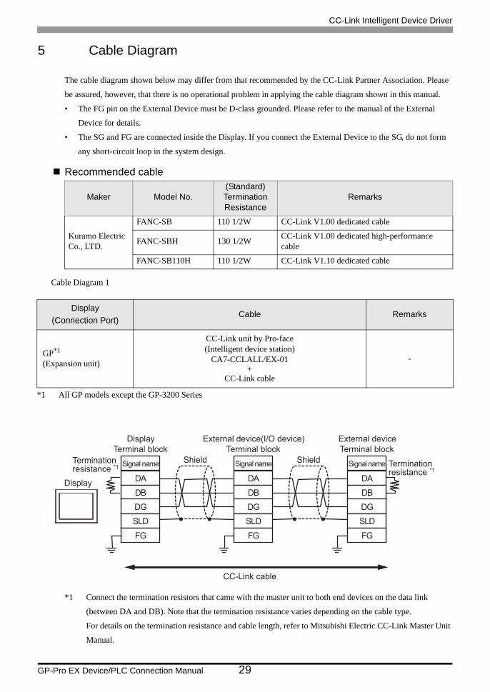
Recommended cable
Cable Diagram 1
*1 Connect the termination resistors that came with the master unit to both end devices on the data link
(between DA and DB). Note that the termination resistance varies depending on the cable type.
For details on the termination resistance and cable length, refer to Mitsubishi Electric CC-Link Master Unit
Manual.
Maker Model No.(Standard)Termination Resistance
Remarks
Kuramo Electric Co., LTD.
FANC-SB 110 1/2W CC-Link V1.00 dedicated cable
FANC-SBH 130 1/2W CC-Link V1.00 dedicated high-performance cable
FANC-SB110H 110 1/2W CC-Link V1.10 dedicated cable
Display(Connection Port)
Cable Remarks
GP*1
(Expansion unit)
*1 All GP models except the GP-3200 Series
CC-Link unit by Pro-face(Intelligent device station)
CA7-CCLALL/EX-01+
CC-Link cable
-
Display
DisplayTerminal block
CC-Link cable
Signal name
DA
DGSLDFG
DB
External deviceTerminal block
DA
DGSLDFG
DB
External device(I/O device)Terminal block
DA
DGSLDFG
DB
Terminationresistance *1
Shield Terminationresistance *1
Signal name Signal nameShield
CC-Link Intelligent Device Driver
GP-Pro EX Device/PLC Connection Manual 30
• Make sure to use a CC-Link dedicated cable for the CC-Link system.• Do not mix different types of cables.• Connect the shield wires to the "SLD" on each unit. The "SLD" is connected internally
to the FG, and so a D-class ground is required for each pin.• For details on T-branch connections, refer to Mitsubishi Electric CC-Link Master Unit
Manual.
CC-Link Intelligent Device Driver
GP-Pro EX Device/PLC Connection Manual 31
6 Supported Devices
The following table shows the range of supported device addresses. Note that the actually supported range varies
depending on the External Device to be used. Please check the actual range in the manual of your External
Device.
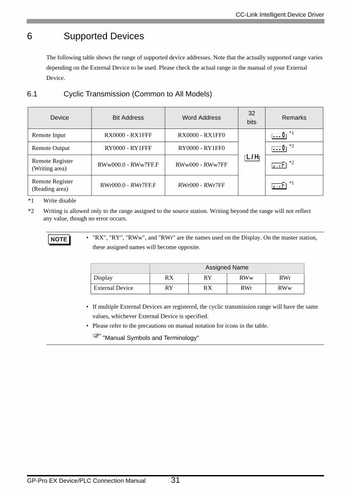
6.1 Cyclic Transmission (Common to All Models)
Device Bit Address Word Address32bits
Remarks
Remote Input RX0000 - RX1FFF RX0000 - RX1FF0 *1
*1 Write disable
Remote Output RY0000 - RY1FFF RY0000 - RY1FF0 *2
*2 Writing is allowed only to the range assigned to the source station. Writing beyond the range will not reflectany value, though no error occurs.
Remote Register(Writing area) RWw000.0 - RWw7FF.F RWw000 - RWw7FF *2
Remote Register(Reading area) RWr000.0 - RWr7FF.F RWr000 - RWr7FF *1
• "RX", "RY", "RWw", and "RWr" are the names used on the Display. On the master station, these assigned names will become opposite.
• If multiple External Devices are registered, the cyclic transmission range will have the same values, whichever External Device is specified.
• Please refer to the precautions on manual notation for icons in the table.
"Manual Symbols and Terminology"
Assigned Name
Display RX RY RWw RWr
External Device RY RX RWr RWw
CC-Link Intelligent Device Driver
GP-Pro EX Device/PLC Connection Manual 32
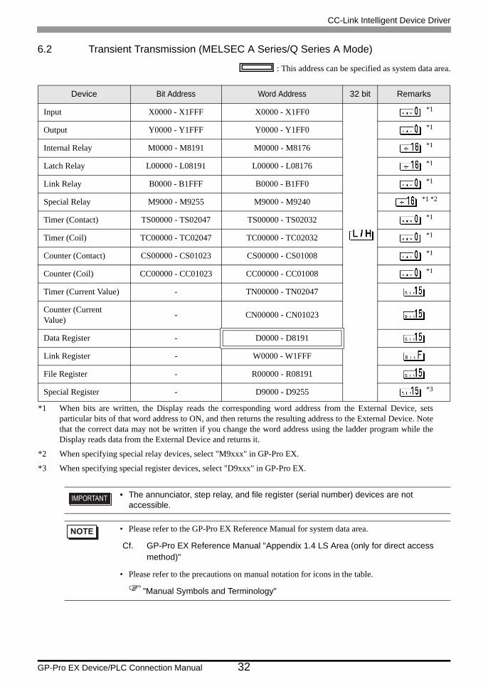
6.2 Transient Transmission (MELSEC A Series/Q Series A Mode)
: This address can be specified as system data area.
Device Bit Address Word Address 32 bit Remarks
Input X0000 - X1FFF X0000 - X1FF0 *1
*1 When bits are written, the Display reads the corresponding word address from the External Device, setsparticular bits of that word address to ON, and then returns the resulting address to the External Device. Notethat the correct data may not be written if you change the word address using the ladder program while theDisplay reads data from the External Device and returns it.
Output Y0000 - Y1FFF Y0000 - Y1FF0 *1
Internal Relay M0000 - M8191 M0000 - M8176 *1
Latch Relay L00000 - L08191 L00000 - L08176 *1
Link Relay B0000 - B1FFF B0000 - B1FF0 *1
Special Relay M9000 - M9255 M9000 - M9240 *1 *2
*2 When specifying special relay devices, select "M9xxx" in GP-Pro EX.
Timer (Contact) TS00000 - TS02047 TS00000 - TS02032 *1
Timer (Coil) TC00000 - TC02047 TC00000 - TC02032 *1
Counter (Contact) CS00000 - CS01023 CS00000 - CS01008 *1
Counter (Coil) CC00000 - CC01023 CC00000 - CC01008 *1
Timer (Current Value) - TN00000 - TN02047
Counter (Current Value) - CN00000 - CN01023
Data Register - D0000 - D8191
Link Register - W0000 - W1FFF
File Register - R00000 - R08191
Special Register - D9000 - D9255 *3
*3 When specifying special register devices, select "D9xxx" in GP-Pro EX.
• The annunciator, step relay, and file register (serial number) devices are not accessible.
• Please refer to the GP-Pro EX Reference Manual for system data area.
Cf. GP-Pro EX Reference Manual "Appendix 1.4 LS Area (only for direct access method)"
• Please refer to the precautions on manual notation for icons in the table.
"Manual Symbols and Terminology"
CC-Link Intelligent Device Driver
GP-Pro EX Device/PLC Connection Manual 33
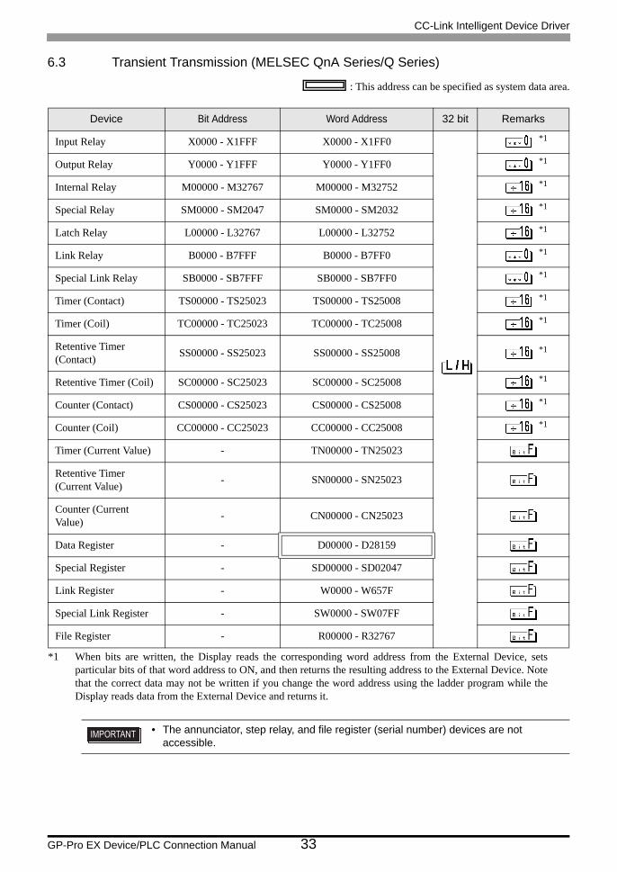
6.3 Transient Transmission (MELSEC QnA Series/Q Series)
: This address can be specified as system data area.
Device Bit Address Word Address 32 bit Remarks
Input Relay X0000 - X1FFF X0000 - X1FF0 *1
*1 When bits are written, the Display reads the corresponding word address from the External Device, setsparticular bits of that word address to ON, and then returns the resulting address to the External Device. Notethat the correct data may not be written if you change the word address using the ladder program while theDisplay reads data from the External Device and returns it.
Output Relay Y0000 - Y1FFF Y0000 - Y1FF0 *1
Internal Relay M00000 - M32767 M00000 - M32752 *1
Special Relay SM0000 - SM2047 SM0000 - SM2032 *1
Latch Relay L00000 - L32767 L00000 - L32752 *1
Link Relay B0000 - B7FFF B0000 - B7FF0 *1
Special Link Relay SB0000 - SB7FFF SB0000 - SB7FF0 *1
Timer (Contact) TS00000 - TS25023 TS00000 - TS25008 *1
Timer (Coil) TC00000 - TC25023 TC00000 - TC25008 *1
Retentive Timer (Contact) SS00000 - SS25023 SS00000 - SS25008 *1
Retentive Timer (Coil) SC00000 - SC25023 SC00000 - SC25008 *1
Counter (Contact) CS00000 - CS25023 CS00000 - CS25008 *1
Counter (Coil) CC00000 - CC25023 CC00000 - CC25008 *1
Timer (Current Value) - TN00000 - TN25023
Retentive Timer (Current Value) - SN00000 - SN25023
Counter (Current Value) - CN00000 - CN25023
Data Register - D00000 - D28159
Special Register - SD00000 - SD02047
Link Register - W0000 - W657F
Special Link Register - SW0000 - SW07FF
File Register - R00000 - R32767
• The annunciator, step relay, and file register (serial number) devices are not accessible.
CC-Link Intelligent Device Driver
GP-Pro EX Device/PLC Connection Manual 34
• Please refer to the GP-Pro EX Reference Manual for system data area.
Cf. GP-Pro EX Reference Manual "Appendix 1.4 LS Area (only for direct access method)"
• Please refer to the precautions on manual notation for icons in the table.
"Manual Symbols and Terminology"
CC-Link Intelligent Device Driver
GP-Pro EX Device/PLC Connection Manual 35
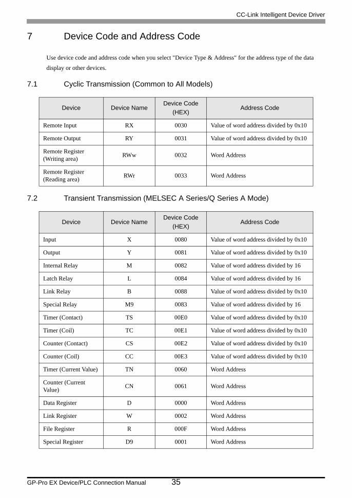
7 Device Code and Address Code
Use device code and address code when you select "Device Type & Address" for the address type of the data
display or other devices.
7.1 Cyclic Transmission (Common to All Models)
7.2 Transient Transmission (MELSEC A Series/Q Series A Mode)
Device Device NameDevice Code
(HEX)Address Code
Remote Input RX 0030 Value of word address divided by 0x10
Remote Output RY 0031 Value of word address divided by 0x10
Remote Register(Writing area) RWw 0032 Word Address
Remote Register(Reading area) RWr 0033 Word Address
Device Device NameDevice Code
(HEX)Address Code
Input X 0080 Value of word address divided by 0x10
Output Y 0081 Value of word address divided by 0x10
Internal Relay M 0082 Value of word address divided by 16
Latch Relay L 0084 Value of word address divided by 16
Link Relay B 0088 Value of word address divided by 0x10
Special Relay M9 0083 Value of word address divided by 16
Timer (Contact) TS 00E0 Value of word address divided by 0x10
Timer (Coil) TC 00E1 Value of word address divided by 0x10
Counter (Contact) CS 00E2 Value of word address divided by 0x10
Counter (Coil) CC 00E3 Value of word address divided by 0x10
Timer (Current Value) TN 0060 Word Address
Counter (Current Value) CN 0061 Word Address
Data Register D 0000 Word Address
Link Register W 0002 Word Address
File Register R 000F Word Address
Special Register D9 0001 Word Address
CC-Link Intelligent Device Driver
GP-Pro EX Device/PLC Connection Manual 36
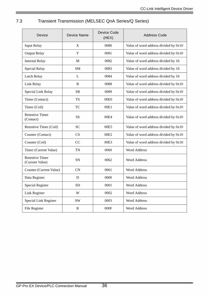
7.3 Transient Transmission (MELSEC QnA Series/Q Series)
Device Device NameDevice Code
(HEX)Address Code
Input Relay X 0080 Value of word address divided by 0x10
Output Relay Y 0081 Value of word address divided by 0x10
Internal Relay M 0082 Value of word address divided by 16
Special Relay SM 0083 Value of word address divided by 16
Latch Relay L 0084 Value of word address divided by 16
Link Relay B 0088 Value of word address divided by 0x10
Special Link Relay SB 0089 Value of word address divided by 0x10
Timer (Contact) TS 00E0 Value of word address divided by 0x10
Timer (Coil) TC 00E1 Value of word address divided by 0x10
Retentive Timer (Contact) SS 00E4 Value of word address divided by 0x10
Retentive Timer (Coil) SC 00E5 Value of word address divided by 0x10
Counter (Contact) CS 00E2 Value of word address divided by 0x10
Counter (Coil) CC 00E3 Value of word address divided by 0x10
Timer (Current Value) TN 0060 Word Address
Retentive Timer (Current Value) SN 0062 Word Address
Counter (Current Value) CN 0061 Word Address
Data Register D 0000 Word Address
Special Register SD 0001 Word Address
Link Register W 0002 Word Address
Special Link Register SW 0003 Word Address
File Register R 000F Word Address
CC-Link Intelligent Device Driver
GP-Pro EX Device/PLC Connection Manual 37
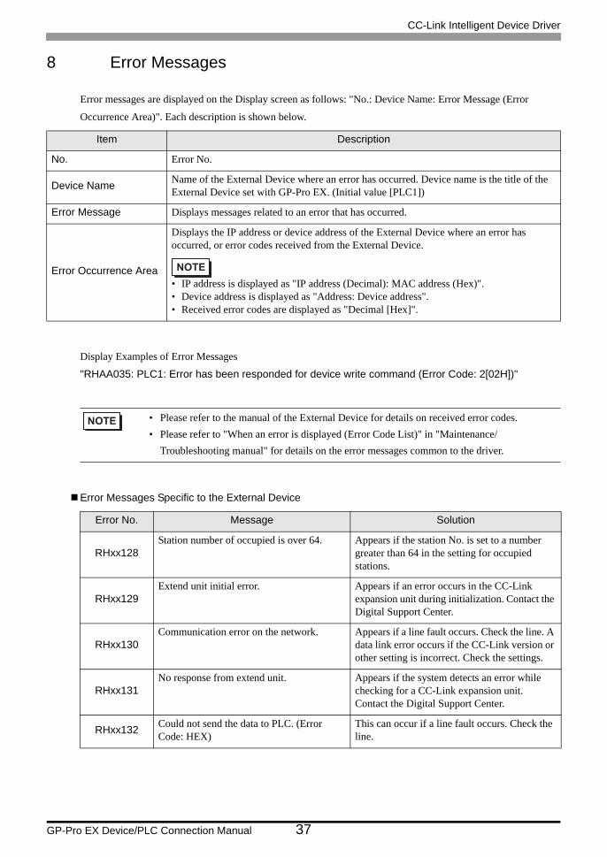
8 Error Messages
Error messages are displayed on the Display screen as follows: "No.: Device Name: Error Message (Error
Occurrence Area)". Each description is shown below.
Display Examples of Error Messages
"RHAA035: PLC1: Error has been responded for device write command (Error Code: 2[02H])"
Error Messages Specific to the External Device
Item Description
No. Error No.
Device Name Name of the External Device where an error has occurred. Device name is the title of the External Device set with GP-Pro EX. (Initial value [PLC1])
Error Message Displays messages related to an error that has occurred.
Error Occurrence Area
Displays the IP address or device address of the External Device where an error has occurred, or error codes received from the External Device.
• IP address is displayed as "IP address (Decimal): MAC address (Hex)".• Device address is displayed as "Address: Device address".• Received error codes are displayed as "Decimal [Hex]".
• Please refer to the manual of the External Device for details on received error codes.• Please refer to "When an error is displayed (Error Code List)" in "Maintenance/
Troubleshooting manual" for details on the error messages common to the driver.
Error No. Message Solution
RHxx128Station number of occupied is over 64. Appears if the station No. is set to a number
greater than 64 in the setting for occupied stations.
RHxx129Extend unit initial error. Appears if an error occurs in the CC-Link
expansion unit during initialization. Contact the Digital Support Center.
RHxx130Communication error on the network. Appears if a line fault occurs. Check the line. A
data link error occurs if the CC-Link version or other setting is incorrect. Check the settings.
RHxx131No response from extend unit. Appears if the system detects an error while
checking for a CC-Link expansion unit. Contact the Digital Support Center.
RHxx132 Could not send the data to PLC. (Error Code: HEX)
This can occur if a line fault occurs. Check the line.

CC-Link Intelligent Device Driver
GP-Pro EX Device/PLC Connection Manual 38
Recommended