Operating Manual STX Advanced Series
CCD Cameras
SBIG Imaging Systems A Division of Diffraction Limited. 59 Grenfell Crescent, Unit B, Ottawa, ON Canada, k2G 0G3
Tel: 613.225.2732 | Fax: 225.225.9688| E-mail: [email protected] | www.sbig.com
© 2016 Diffraction Limited. All rights reserved. The SBIG logo are trademarks of Diffraction Limited, All other trademarks, service marks and tradenames appearing in this brochure are the property of their respective owners.

Note: This equipment has been tested and found to comply with the limits for a Class B digital device pursuant to Part 15 of the FCC Rules. These limits are designed to provide reasonable protection against harmful interference in a residential installation. This equipment generates, uses, and can radiate radio frequency energy and if not installed and used in accordance with the instructions, may cause harmful interference to radio communications. However, there is no guarantee that interference will not occur in a particular installation. If this equipment does cause harmful interference to radio or television reception, which can be determined by turning the equipment off and on, the user is encouraged to try to correct the interference by one or more of the following measures:
• Reorient or relocate the receiving antenna.• Increase the separation between the receiver and the equipment.• Connect the equipment into an outlet on a circuit different from that to which the receiver is
connected.• Consult the dealer or an experienced radio/TV technician for help.
Shielded I/O cables must be used when operating this equipment. You are also warned, that any changes to this certified device will void your legal right to operate it.
OPERATION Manual for STX Series Cameras Revision 1.3 Dec 2016
2
TABLE OF CONTENTS
1.0. CAMERA HARDWARE ...................................................................................................................................... 4 1.1. Introduction and Overview .......................................................................................................... 4 1.2. Unpacking the Camera .................................................................................................................. 4
Standard Items:....................................................................................................................... 6 Optional Items: ....................................................................................................................... 7
1.3. Parts and Assembly ....................................................................................................................... 8 1.4. Connectors....................................................................................................................................... 9
[A] Tracking CCD Focus Adjustment................................................................................. 9 [B] Remote Guide Head Port ............................................................................................... 9 [C] USB Port ........................................................................................................................... 9 [D] SCOPE Port.....................................................................................................................10 [E] I2C-AUX Port ..................................................................................................................10 [F] Ethernet............................................................................................................................10 [G] Power...............................................................................................................................10 [H] Water In / Out ...............................................................................................................10
1.5. Attaching the camera to a telescope. ..........................................................................................11 1.6. Connecting the Relay Cable .........................................................................................................11 1.7. Attaching the Remote Head.........................................................................................................11 1.8. Connecting water hoses................................................................................................................12 1.9. Extending the USB cable ..............................................................................................................12 1.10. Opening the Front Cover - Regenerating the Desiccant Plug................................................13 1.11. Gas Purging..................................................................................................................................14 1.12. Indicator Lights ...........................................................................................................................14 1.13. Opening the Back Cover - Changing the Fuse.........................................................................15 1.14. Using a Relay Adapter Box with the STX ................................................................................15 1.15. Camera Resolution......................................................................................................................17 1.16. Camera Field of View .................................................................................................................18 1.17. Focal Length, Resolution and Field of View............................................................................19
2.0. CAMERA SOFTWARE .......................................................................................................................................20 2.1 Installing Software .........................................................................................................................20
Installing CCDOps ................................................................................................................20 Installing the SBIG Drivers...................................................................................................20 Linking the Drivers ...............................................................................................................21
2.2. Using the Camera..........................................................................................................................22 Establishing a Link with CCDOps ......................................................................................22 Camera Setup.........................................................................................................................22 Taking Sample Dark Frames................................................................................................22 Further Investigations...........................................................................................................23
2.3. Specific Activities ..........................................................................................................................23 Ethernet Configuration.........................................................................................................23 Web Browser ..........................................................................................................................23 Making the Autoguiding Connection.................................................................................23
2.4. Third Party Software.....................................................................................................................24 CCDSoft ..................................................................................................................................24 MaximDl .................................................................................................................................24
Support and Developer Resources......................................................................................................24
Appendix A – Adjustments and Maintenance .......................................................................................................25 Firmware Updates.................................................................................................................................25 Internal Tracker Focus ..........................................................................................................................25 Desiccant Regeneration ........................................................................................................................25 Cleaning the CCD and the Window ...................................................................................................26
3
Appendix B - Capturing a Good Flat Field .............................................................................................................27 B-1. Technique ......................................................................................................................................27
Appendix C – Camera Specifications.......................................................................................................................28
Appendix D – Connector and Cables.......................................................................................................................29 Power Jack .....................................................................................................................................................................29 Scope Port ......................................................................................................................................................................29 I2C/AUX Port ...............................................................................................................................................................29
4
The SBIG STX Series represents the ultimate in astronomical imaging systems. The integrated design allows the user to select either Ethernet or high speed USB 2.0 connection to the control computer. The Model STX-16803 uses Kodak’s KAF-16803 CCD with 16 million pixels at 9 microns. The sensor measures almost 37mm square. The built-in tracking CCD is a Kodak KAI-340S with 640 x 480 pixels at 7.4 microns. The STX series has superior cooling to -50 degrees C below ambient with air only. Water-cooling is also possible.
Built-in Guiding CCD with Adjustable Focus: The guiding CCD in the STX cameras is a KAI-340 CCD with 640 x 480 pixels at 7.4u. As the imaging CCDs get larger, the guiding CCD gets pushed farther away from the center of the optical axis. Depending on the nature of the optical system, this can cause the image on the guiding CCD to be slightly out of focus when the image on the main CCD is in focus. To address this, STX cameras have a user accessible adjustment for changing the focal point of the on-board guiding CCD.
For external guiding, the same same KAI-340 CCD is also used the optional Remote Guide Head, and in the new STX Guider accessory for the FW7-STX filter wheel. The STX Guider allows you to use the smaller, less expensive 50 mm square filters, and increases the guider FOV with focal reduction optics. The smaller filters also mean that the FW7-STX wheel can hold 7 filters instead of 5.
Product Description
5
1.0. CAMERA HARDWARE
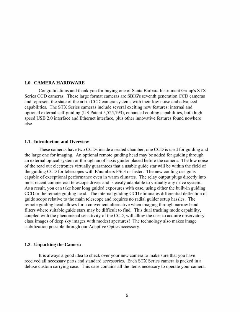
Congratulations and thank you for buying one of Santa Barbara Instrument Group's STX Series CCD cameras. These large format cameras are SBIG's seventh generation CCD cameras and represent the state of the art in CCD camera systems with their low noise and advanced capabilities. The STX Series cameras include several exciting new features: internal and optional external self-guiding (US Patent 5,525,793), enhanced cooling capabilities, both high speed USB 2.0 interface and Ethernet interface, plus other innovative features found nowhere else.
1.1. Introduction and Overview
These cameras have two CCDs inside a sealed chamber, one CCD is used for guiding and the large one for imaging. An optional remote guiding head may be added for guiding through an external optical system or through an off-axis guider placed before the camera. The low noise of the read out electronics virtually guarantees that a usable guide star will be within the field of the guiding CCD for telescopes with F/numbers F/6.3 or faster. The new cooling design is capable of exceptional performance even in warm climates. The relay output plugs directly into most recent commercial telescope drives and is easily adaptable to virtually any drive system. As a result, you can take hour long guided exposures with ease, using either the built-in guiding CCD or the remote guiding head. The internal guiding CCD eliminates differential deflection of guide scope relative to the main telescope and requires no radial guider setup hassles. The remote guiding head allows for a convenient alternative when imaging through narrow band filters where suitable guide stars may be difficult to find. This dual tracking mode capability, coupled with the phenomenal sensitivity of the CCD, will allow the user to acquire observatory class images of deep sky images with modest apertures! The technology also makes image stabilization possible through our Adaptive Optics accessory.
1.2. Unpacking the Camera
It is always a good idea to check over your new camera to make sure that you have received all necessary parts and standard accessories. Each STX Series camera is packed in a deluxe custom carrying case. This case contains all the items necessary to operate your camera.
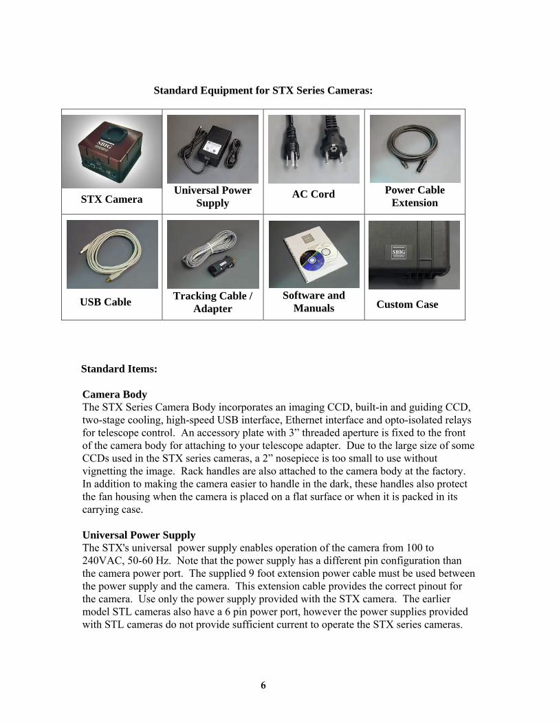
Standard Equipment for STX Series Cameras:
STX Camera Universal Power
Supply AC Cord Power Cable
Extension
USB Cable Tracking Cable / Adapter
Software and Manuals Custom Case
Standard Items:
Camera Body The STX Series Camera Body incorporates an imaging CCD, built-in and guiding CCD, two-stage cooling, high-speed USB interface, Ethernet interface and opto-isolated relays for telescope control. An accessory plate with 3” threaded aperture is fixed to the front of the camera body for attaching to your telescope adapter. Due to the large size of some CCDs used in the STX series cameras, a 2” nosepiece is too small to use without vignetting the image. Rack handles are also attached to the camera body at the factory. In addition to making the camera easier to handle in the dark, these handles also protect the fan housing when the camera is placed on a flat surface or when it is packed in its carrying case.
Universal Power Supply The STX's universal power supply enables operation of the camera from 100 to 240VAC, 50-60 Hz. Note that the power supply has a different pin configuration than the camera power port. The supplied 9 foot extension power cable must be used between the power supply and the camera. This extension cable provides the correct pinout for the camera. Use only the power supply provided with the STX camera. The earlier model STL cameras also have a 6 pin power port, however the power supplies provided with STL cameras do not provide sufficient current to operate the STX series cameras.
6
Power Supply Extension Cable This 9 foot cable extends the distance the power supply may be placed away from the camera. It is also much more flexible than the short lead provided with the power supply. Finally, the extension cable adapts the four-pin output of the power supply to the six-pin DIN plug at the camera.
Regional AC Cord and Plug AC cords with either European or North American style plugs are provided. Must specify at time of order.
14’ USB Cable A standard 14’ USB cable is supplied
Relay Cable The tracking cable is a 6 conductor flat cable with 6 pin modular telephone style plugs at both ends
Software and Manuals A complete package of camera control software, drivers for both 32 bit and 64 bit Windows O/S and manuals are included.
Custom Case Carrying cases provided for the STX Series cameras are high quality, waterproof, dustproof, crushproof .
Optional Items:
Remote Guide Head The optional STX Remote Guide Head contains a KAI-340S CCD identical to the guiding CCD that is built into the camera. This remote head allows you to use a separate guide scope or off-axis guider to place the guiding CCD outside the filter wheel for convenience when imaging through narrow band filters or anytime you wish to use an external guider.
FW5-STX, FW7-STX Filter Wheel50mm and 65 mm filter wheels are available for the STX camera. Filter sets are offered by Baader Planetarium, Custom Scientific and Astrodon.
STX Guider
This product attaches to the front of a FW7-STX filter wheel, turning it into a self-guiding filter wheel. The STX Guider is directly compatible with the AO-X adaptive optics unit.
AO-X
The SBIG AO-X is a large aperture AO designed to be compatible with all STX and STXL series cameras, including the STX-16803, STXL-16200, STXL-11000 and STXL-6303. The AO-X requies minimal backfocus while offering a large 3″ aperture optical element, which is large enough to cover the KAF-16803 CCD sensor.
7
8
Nikon and Canon Lens Adapters Adapter allows the use of Canon or Nikon 35mm camera lenses on Research Series cameras for wide field imaging.
1.3. Parts and Assembly
The black anodized portion of the camera body contains the CCD chamber, electronics, desiccant plug, gas purge valve, heat exchanger, fan and a power supply for 12VDC operation in the field. The red front cover contains the shutter mechanism and mounting plate with 3 inch threads. The front cover may be removed from the camera body without exposing the CCD chamber to the air. The accessory plate is shimmed at the factory to provide a flat mounting surface that is parallel to the CCD. Under normal use, it should not be removed. If it is removed, please note the location of the shims around the screws holding the plate to the front cover so that they may be replaced in the same configuration. The rear cover has rack handles, fan and heat sink, plus ventilation slots for air circulation. Two water circulation fittings are found on the side of the camera opposite the power and other electrical connections. Access to the gas purge valve is inside the front cover, next to the desiccant plug, on the CCD chamber.
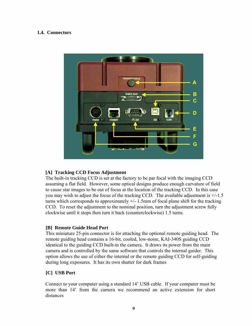
1.4. Connectors
[A] Tracking CCD Focus AdjustmentThe built-in tracking CCD is set at the factory to be par focal with the imaging CCDassuming a flat field. However, some optical designs produce enough curvature of fieldto cause star images to be out of focus at the location of the tracking CCD. In this caseyou may wish to adjust the focus of the tracking CCD. The available adjustment is +/-1.5turns which corresponds to approximately +/- 1.5mm of focal plane shift for the trackingCCD. To reset the adjustment to the nominal position, turn the adjustment screw fullyclockwise until it stops then turn it back (counterclockwise) 1.5 turns.
[B] Remote Guide Head PortThis miniature 25-pin connector is for attaching the optional remote guiding head. Theremote guiding head contains a 16-bit, cooled, low-noise, KAI-340S guiding CCDidentical to the guiding CCD built-in the camera. It draws its power from the maincamera and is controlled by the same software that controls the internal guider. Thisoption allows the use of either the internal or the remote guiding CCD for self-guidingduring long exposures. It has its own shutter for dark frames
[C] USB Port
Connect to your computer using a standard 14’ USB cable. If your computer must be more than 14’ from the camera we recommend an active extension for short distances
9
(14’ additional) such as a powered USB. For longer distances the Icron Ranger allows USB devices to operate up to 100 meters from the host computer. For long runs we recommend using the Ethernet interface with CAT5e cable (see [F] below).
[D] SCOPE PortThis port supplies the relay outputs for controlling the guiding of your telescope.Connect the supplied 6-conductor telephone style cable to this connector and the otherend of the cable to your telescope drive's autoguider input port. See Section 1.6 for moreinformation.
[E] I2C-AUX Port
This port is for attachment of accessories: SBIG filter wheels, Adaptive Optics, etc. Accessories designed to use this port do not require separate power supplies or control cables running to the computer.
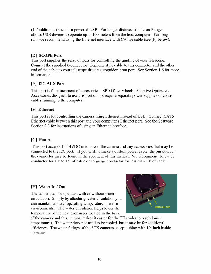
[H] Water In / Out
[F
This port is forEthernet cable between this port and your computer's Ethernet port. See the Software Section 2.3 for instructions of using an Ethernet interface.
[G] Power
10
] Ethernet
controlling the camera using Ethernet instead of USB. Connect CAT5
This port accepts 13-14VDC in to power the camera and any accessories that may be connected to the I2C port. If you wish to make a custom power cable, the pin outs for the connector may be found in the appendix of this manual. We recommend 16 gauge conductor for 10’ to 15’ of cable or 18 gauge conductor for less than 10’ of cable.
The camera can be operated with or without water circulation. Simply by attaching water circulation you can maintain a lower operating temperature in warm environments. The water circulation helps lower the temperature of the heat exchanger located in the back of the camera and this, in turn, makes it easier for the TE cooler to reach lower temperatures. The water does not need to be cooled, but it may be for additional efficiency. The water fittings of the STX cameras accept tubing with 1/4 inch inside diameter.
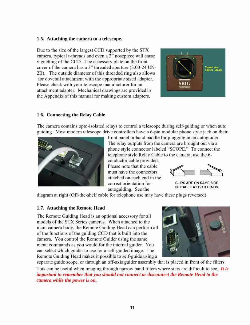
1.5. Attaching the camera to a telescope.
ue to the size of the largest CCD supported by the STX se
N-
in
1.6. Connecting the Relay Cable
he camera contains opto-isolated relays to control a telescope during self-guiding or when auto
diagram at right (Off-the-shelf cable
1.7. Attaching the Remote Head
ional accessory for all
all
u
Tguiding. Most modern telescope drive controllers have a 6-pin modular phone style jack on their
front panel or hand paddle for plugging in an autoguider. The relay outputs from the camera are brought out via a phone style connector labeled “SCOPE.” To connect thetelephone style Relay Cable to the camera, use the 6-conductor cable provided. Please note that the cable must have the connectors attached on each end in thecorrect orientation for autoguiding. See the for telephone use may have these plugs reversed).
The Remote Guiding Head is an optmodels of the STX Series cameras. When attached to the main camera body, the Remote Guiding Head can performof the functions of the guiding CCD that is built into the camera. You control the Remote Guider using the same menu commands as you would for the internal guider. Yocan select which guider to use for a self-guided image. The Remote Guiding Head makes it possible to self-guide using aseparate guide scope, or through an off-axis guider assembly that is placed in front of the filters.
11
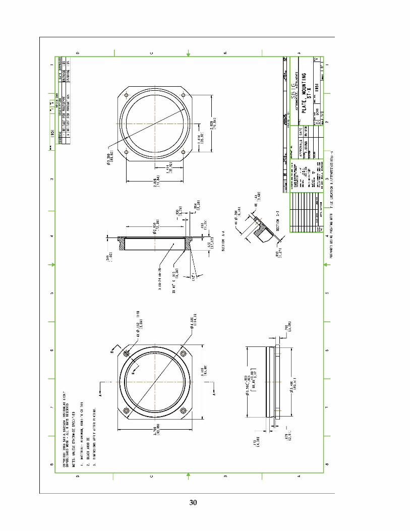
Dcamera, typical t-threads and even a 2” nosepiece will cauvignetting of the CCD. The accessory plate on the front cover of the camera has a 3” threaded aperture (3.00-24 U2B). The outside diameter of this threaded ring also allows for dovetail attachment with the appropriate sized adapter. Please check with your telescope manufacturer for an attachment adapter. Mechanical drawings are providedthe Appendix of this manual for making custom adapters.
This can be useful when imaging through narrow band filters where stars are difficult to see. It is important to remember that you should not connect or disconnect the Remote Head to the camera while the power is on.
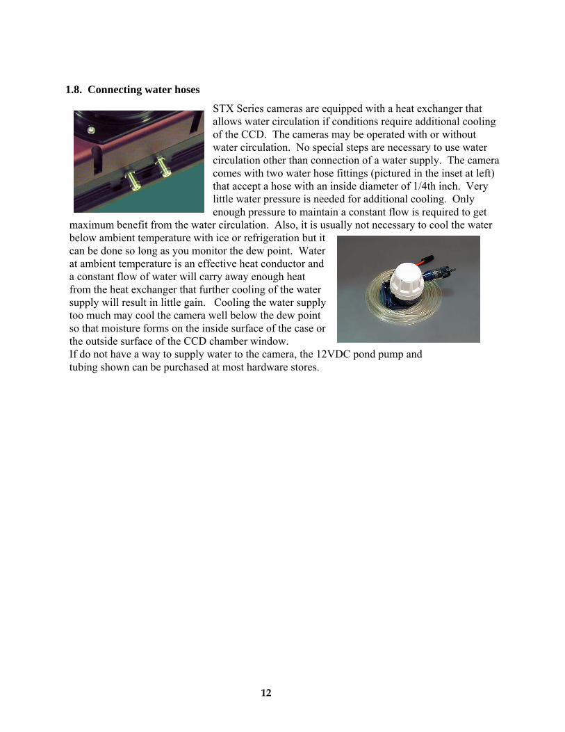
1.8. Connecting water hoses
STX Series cameras are equipped with a heat exchanger that g
r
t the water circulation. Also, it is usually not necessary to cool the water
allows water circulation if conditions require additional coolinof the CCD. The cameras may be operated with or without water circulation. No special steps are necessary to use watecirculation other than connection of a water supply. The camera comes with two water hose fittings (pictured in the inset at left) that accept a hose with an inside diameter of 1/4th inch. Very little water pressure is needed for additional cooling. Only enough pressure to maintain a constant flow is required to ge
below ambient temperature with ice or refrigeration but it can be done so long as you monitor the dew point. Water at ambient temperature is an effective heat conductor and
maximum benefit from
a constant flow of water will carry away enough heat from the heat exchanger that further cooling of the water supply will result in little gain. Cooling the water supply too much may cool the camera well below the dew point so that moisture forms on the inside surface of the case or the outside surface of the CCD chamber window. If do not have a way to supply water to the camera, the 12VDC pond pump and tubing shown can be purchased at most hardware stores.
12
Powered USB extenders. Powered extenders such as the Icron Ranger (www.icron.com) are also commonly available. These extenders require power at one end of the cable (either end) and will let you operate the camera (or any USB device) up to 100 meters from the computer.
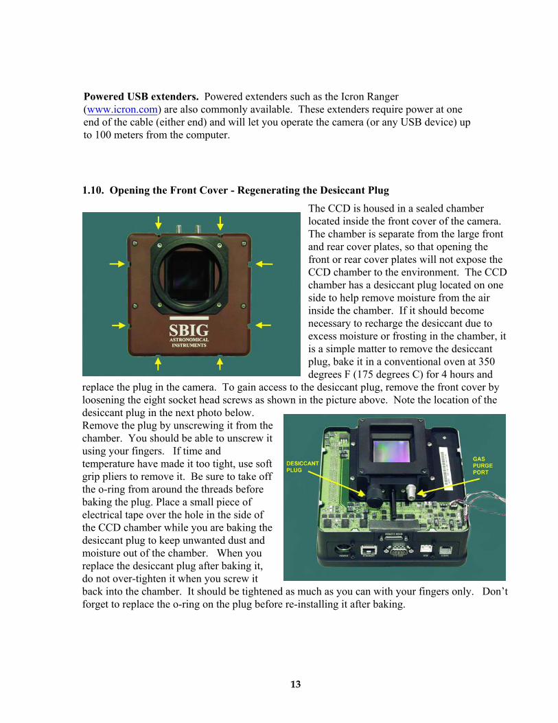
1.10. Opening the Front Cover - Regenerating the Desiccant Plug The CCD is housed in a sealed chamber located inside the front cover of the camera. The chamber is separate from the large front and rear cover plates, so that opening the front or rear cover plates will not expose the CCD chamber to the environment. The CCD chamber has a desiccant plug located on one side to help remove moisture from the air inside the chamber. If it should become necessary to recharge the desiccant due to excess moisture or frosting in the chamber, it is a simple matter to remove the desiccant plug, bake it in a conventional oven at 350 degrees F (175 degrees C) for 4 hours and
replace the plug in the camera. To gain access to the desiccant plug, remove the front cover by loosening the eight socket head screws as shown in the picture above. Note the location of the desiccant plug in the next photo below. Remove the plug by unscrewing it from the chamber. You should be able to unscrew it using your fingers. If time and temperature have made it too tight, use soft grip pliers to remove it. Be sure to take off the o-ring from around the threads before baking the plug. Place a small piece of electrical tape over the hole in the side of the CCD chamber while you are baking the desiccant plug to keep unwanted dust and moisture out of the chamber. When you replace the desiccant plug after baking it, do not over-tighten it when you screw it back into the chamber. It should be tightened as much as you can with your fingers only. Don’t forget to replace the o-ring on the plug before re-installing it after baking.
13
1.11. Gas Purging
Purging the CCD chamber with an inert gas such as Argon can provide a quick dry air chamber and cooling performance may be slightly improved. However, this procedure is generally unnecessary. The gas purge port is therefore included as a convenience, but not a necessity. You should only consider purging the chamber if it is absolutely necessary. The risk is that you may introduce foreign material to the chamber, or worse, destroy the CCD. WARNING: DO NOT PURGE THE CHAMBER UNLESS THE DESICCANT PLUG IS COMPLETELY REMOVED FROM THE CHAMBER. DO NOT PURGE THE CHAMBER WITH THE DESICCANT PLUG SIMPLY LOOSENED BUT LEFT PARTIALLY SCREWED INTO ITS PORT ON THE CHAMBER. Failure to follow these instructions may result is destruction of the CCD and this damage is NOT covered under warranty. The pressure may not exceed 1 or 2 pounds per square inch on the CCD. If you do not have a regulator capable of limiting the gas pressure to about 1 psi, then you should flow the gas through the chamber under very low pressure with an OPEN desiccant plug port (remove the desiccant plug completely) to prevent the pressure from building up inside the chamber. After a few seconds, turn off the gas and only then replace the desiccant plug.
1.12. Indicator Lights
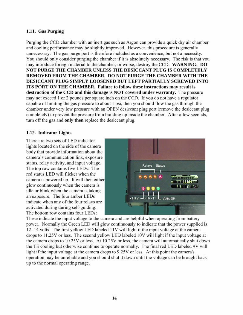
There are two sets of LED indicator lights located on the side of the camera body that provide information about the camera’s communication link, exposure status, relay activity, and input voltage. The top row contains five LEDs: The red status LED will flicker when the camera is powered up. It will then either glow continuously when the camera is idle or blink when the camera is taking an exposure. The four amber LEDs indicate when any of the four relays are activated during during self-guiding. The bottom row contains four LEDs: These indicate the input voltage to the camera and are helpful when operating from battery power. Normally the Green LED will glow continuously to indicate that the power supplied is 12 -14 volts. The first yellow LED labeled 11V will light if the input voltage at the camera drops to 11.25V or less. The second yellow LED labeled 10V will light if the input voltage at the camera drops to 10.25V or less. At 10.25V or less, the camera will automatically shut down the TE cooling but otherwise continue to operate normally. The final red LED labeled 9V will light if the input voltage at the camera drops to 9.25V or less. At this point the camera's operation may be unreliable and you should shut it down until the voltage can be brought back up to the normal operating range.
14
1.13. Opening the Back Cover - Changing the Fuse
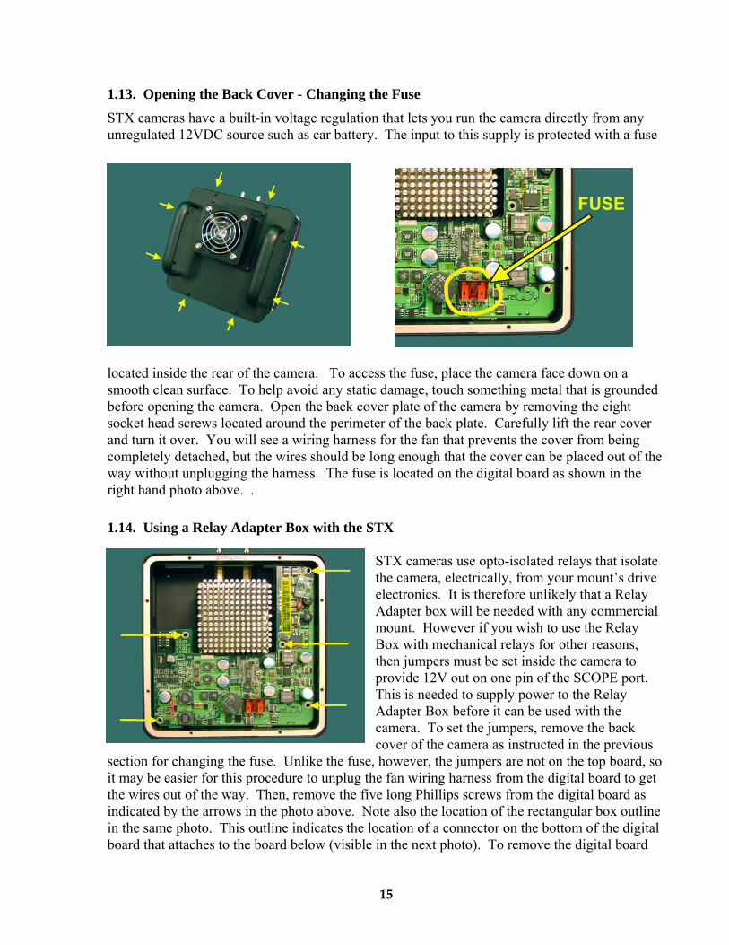
STX cameras have a built-in voltage regulation that lets you run the camera directly from any unregulated 12VDC source such as car battery. The input to this supply is protected with a fuse
located inside the rear of the camera. To access the fuse, place the camera face down on a smooth clean surface. To help avoid any static damage, touch something metal that is grounded before opening the camera. Open the back cover plate of the camera by removing the eight socket head screws located around the perimeter of the back plate. Carefully lift the rear cover and turn it over. You will see a wiring harness for the fan that prevents the cover from being completely detached, but the wires should be long enough that the cover can be placed out of the way without unplugging the harness. The fuse is located on the digital board as shown in the right hand photo above. .
1.14. Using a Relay Adapter Box with the STX
STX cameras use opto-isolated relays that isolate the camera, electrically, from your mount’s drive electronics. It is therefore unlikely that a Relay Adapter box will be needed with any commercial mount. However if you wish to use the Relay Box with mechanical relays for other reasons, then jumpers must be set inside the camera to provide 12V out on one pin of the SCOPE port. This is needed to supply power to the Relay Adapter Box before it can be used with the camera. To set the jumpers, remove the back cover of the camera as instructed in the previous
section for changing the fuse. Unlike the fuse, however, the jumpers are not on the top board, so it may be easier for this procedure to unplug the fan wiring harness from the digital board to get the wires out of the way. Then, remove the five long Phillips screws from the digital board as indicated by the arrows in the photo above. Note also the location of the rectangular box outline in the same photo. This outline indicates the location of a connector on the bottom of the digital board that attaches to the board below (visible in the next photo). To remove the digital board
15
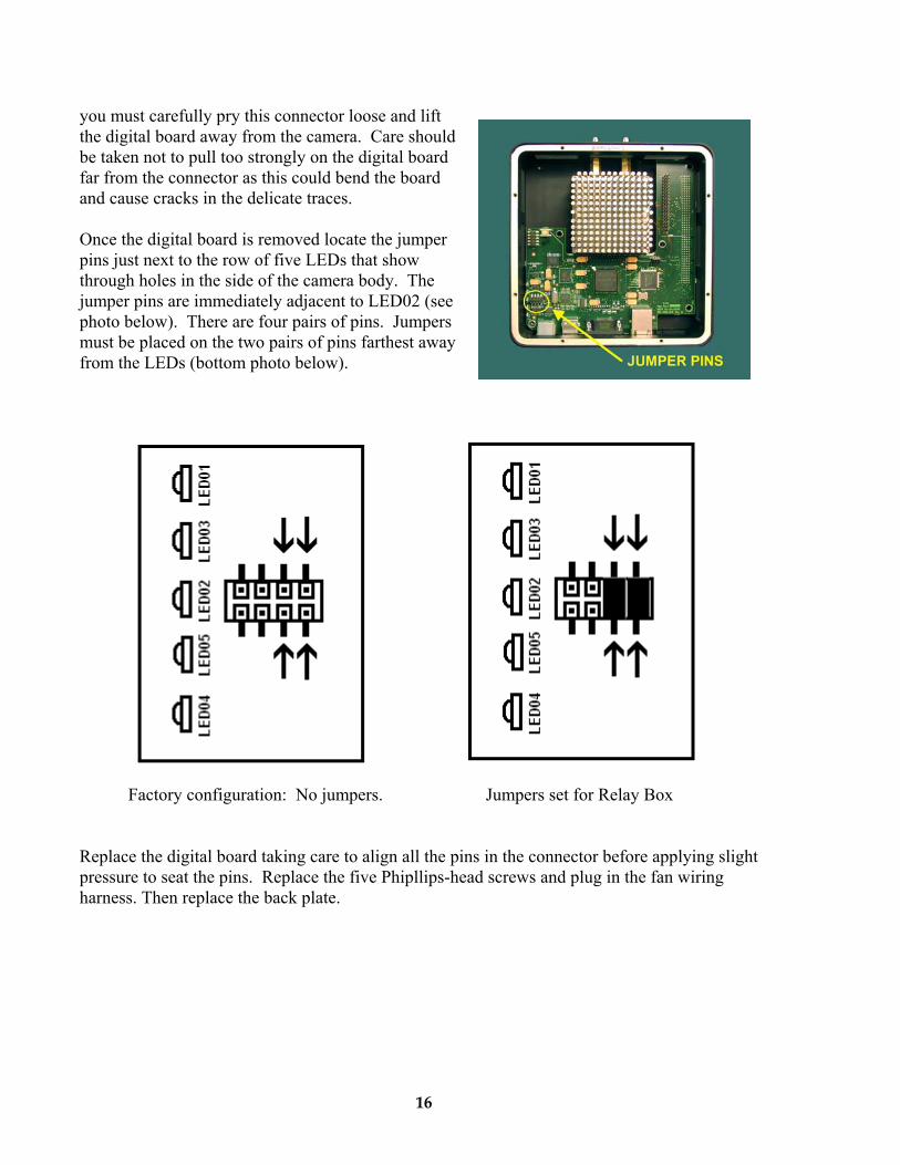
you must carefully pry this connector loose and lift the digital board away from the camera. Care should be taken not to pull too strongly on the digital board far from the connector as this could bend the board and cause cracks in the delicate traces.
Once the digital board is removed locate the jumper pins just next to the row of five LEDs that show through holes in the side of the camera body. The jumper pins are immediately adjacent to LED02 (see photo below). There are four pairs of pins. Jumpers must be placed on the two pairs of pins farthest away from the LEDs (bottom photo below).
Factory configuration: No jumpers. Jumpers set for Relay Box
Replace the digital board taking care to align all the pins in the connector before applying slight pressure to seat the pins. Replace the five Phipllips-head screws and plug in the fan wiring harness. Then replace the back plate.
16
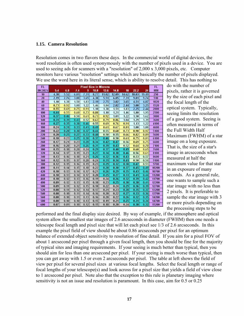
1.15. Camera Resolution
Resolution comes in two flavors these days. In the commercial world of digital devices, the word resolution is often used synonymously with the number of pixels used in a device. You are used to seeing ads for scanners with a "resolution" of 2,000 x 3,000 pixels, etc. Computer monitors have various "resolution" settings which are basically the number of pixels displayed. We use the word here in its literal sense, which is ability to resolve detail. This has nothing to
do with the number of pixels, rather it is governed by the size of each pixel and the focal length of the optical system. Typically, seeing limits the resolution of a good system. Seeing is often measured in terms of the Full Width Half Maximum (FWHM) of a star image on a long exposure. That is, the size of a star's image in arcseconds when measured at half the maximum value for that star in an exposure of many seconds. As a general rule, one wants to sample such a star image with no less than 2 pixels. It is preferable to sample the star image with 3 or more pixels depending on the processing steps to be
performed and the final display size desired. By way of example, if the atmosphere and optical system allow the smallest star images of 2.6 arcseconds in diameter (FWHM) then one needs a telescope focal length and pixel size that will let each pixel see 1/3 of 2.6 arcseconds. In this example the pixel field of view should be about 0.86 arcseconds per pixel for an optimum balance of extended object sensitivity to resolution of fine detail. If you aim for a pixel FOV of about 1 arcsecond per pixel through a given focal length, then you should be fine for the majority of typical sites and imaging requirements. If your seeing is much better than typical, then you should aim for less than one arcsecond per pixel. If your seeing is much worse than typical, then you can get away with 1.5 or even 2 arcseconds per pixel. The table at left shows the field of view per pixel for several pixel sizes at various focal lengths. Select the focal length or range of focal lengths of your telescope(s) and look across for a pixel size that yields a field of view close to 1 arcsecond per pixel. Note also that the exception to this rule is planetary imaging where sensitivity is not an issue and resolution is paramount. In this case, aim for 0.5 or 0.25
17
arcseconds per pixel. Also note that cameras with smaller pixels may be binned 2x2 or 3x3 to create larger pixels and expand the useful range of the camera. For example, an STX-16000 with 7.4 micron pixels can be binned 2x2 to give 14.8 micron pixels. The overall field of view of the CCD does not change however, and a camera with larger pixels and a larger field of view might be preferable if it will not be used on shorter focal length instruments.
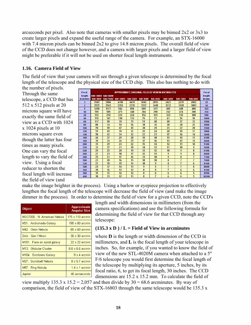
1.16. Camera Field of View
The field of view that your camera will see through a given telescope is determined by the focal length of the telescope and the physical size of the CCD chip. This also has nothing to do with the number of pixels. Through the same telescope, a CCD that has 512 x 512 pixels at 20 microns square will have exactly the same field of view as a CCD with 1024 x 1024 pixels at 10 microns square even though the latter has four times as many pixels. One can vary the focal length to vary the field of view. Using a focal reducer to shorten the focal length will increase the field of view (and make the image brighter in the process). Using a barlow or eyepiece projection to effectively lengthen the focal length of the telescope will decrease the field of view (and make the image dimmer in the process). In order to determine the field of view for a given CCD, note the CCD's
length and width dimensions in millimeters (from the camera specifications) and use the following formula for determining the field of view for that CCD through any telescope:
(135.3 x D ) / L = Field of View in arcminutes
where D is the length or width dimension of the CCD in millimeters, and L is the focal length of your telescope in inches. So, for example, if you wanted to know the field of view of the new STL-4020M camera when attached to a 5" F/6 telescope you would first determine the focal length of the telescope by multiplying its aperture, 5 inches, by its focal ratio, 6, to get its focal length, 30 inches. The CCD dimensions are 15.2 x 15.2 mm. To calculate the field of
view multiply 135.3 x 15.2 = 2,057 and then divide by 30 = 68.6 arcminutes. By way of comparison, the field of view of the STX-16803 through the same telescope would be 135.3 x
18
36.8 = 4,979 divided by 30 = 166 arcminutes. The table above shows the calculated field of view in arcminutes for each of the several large format CCDs at various focal lengths. Keep in mind however that when you vary the CCD field of view you are also varying the field of view for each pixel and are therefore also affecting the resolution of your system.
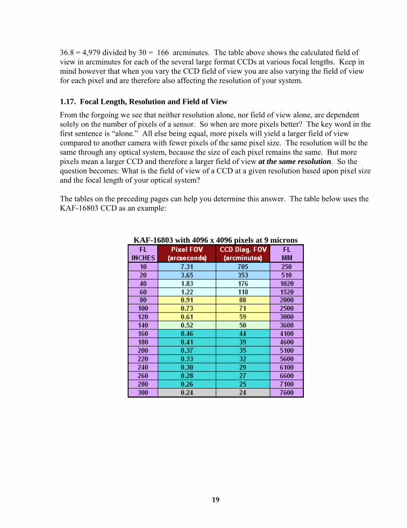
1.17. Focal Length, Resolution and Field of View
From the forgoing we see that neither resolution alone, nor field of view alone, are dependent solely on the number of pixels of a sensor. So when are more pixels better? The key word in the first sentence is “alone.” All else being equal, more pixels will yield a larger field of view compared to another camera with fewer pixels of the same pixel size. The resolution will be the same through any optical system, because the size of each pixel remains the same. But more pixels mean a larger CCD and therefore a larger field of view at the same resolution. So the question becomes: What is the field of view of a CCD at a given resolution based upon pixel size and the focal length of your optical system?
The tables on the preceding pages can help you determine this answer. The table below uses the KAF-16803 CCD as an example:
KAF-16803 with 4096 x 4096 pixels at 9 microns
19
2.0. CAMERA SOFTWARE
This section gets you up and running right away with your STX camera. First you’ll install the Application Software and Drivers, then you’ll have Windows Link the Drivers to the Camera and finally you’ll connect to the Camera and take a few sample images. Please follow these instructions in order and do not attach your Camera to your Computer until instructed. Note: The STX Drivers require Windows Vista, Windows 7, Windows 8, Windows 10 .
They will not work under older Windows versions like Windows 98, XP
2.1 Installing Software
Before you can use your camera you’ll have to install the CCDOps Application software and the Windows Drivers for the camera. We’ll walk you through that in this section.
Installing CCDOps MAC WINDOWS
SBIG’s Application Software for our cameras is called CCDOps. It gives you full control of your camera’s features. To install CCDOps follow the instructions below: • Insert the CD-ROM that came with your camera into your computer’s CD drive.
If the CD doesn’t auto-run Explore the CD and run the autorun.exe file in theroot directory.
• Click the Setup New ST Camera button.• Click on the Install CCDOps button and follow the onscreen instructions.
Installing the SBIG Drivers MAC WINDOWS SBIG Cameras require Drivers to be installed in Windows or Mac before you can communicate with them. Our Driver Checker program downloads the latest Drivers from our website and Installs them on your computer. Follow the instructions below to install the SBIG Drivers for your camera:
• Install 64-Bit Driver Checker. You must use the 64-Bit Driver Checker with theSTX and it works on both 32 and 64 bit versions of Windows.
• Follow the onscreen instructions to install the Driver Checker. At the end of theInstall opt to Launch the SBIG Driver Checker.
• The Driver Checker will ask you about any older ST Series Camera you mayhave with or without the Remote Guide Head capability. Read the optionscarefully, select the appropriate setting then click OK. Click on the Updatebutton to Install the Drivers.. In the process of installing the drivers it will showyou a ReadMe file with notes about the current drivers and it will ask you toverify that you want to apply the Update. After clicking Update Me it will installthe drivers on your system.
• Before you quit the Driver Checker you should see that all the Drivers are listedas Current in the table as shown below. If not click on the Download button toDownload the latest Drivers from our web site then click the Update button a 2nd
20
time. Your versions may be different than those shown.
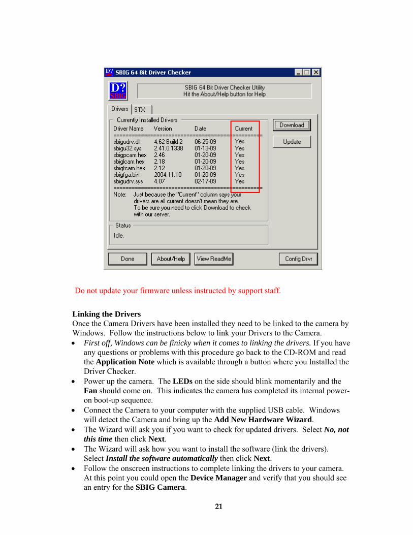
Linking the Drivers Once the Camera Drivers have been installed they need to be linked to the camera by Windows. Follow the instructions below to link your Drivers to the Camera. • First off, Windows can be finicky when it comes to linking the drivers. If you have
any questions or problems with this procedure go back to the CD-ROM and readthe Application Note which is available through a button where you Installed theDriver Checker.
• Power up the camera. The LEDs on the side should blink momentarily and theFan should come on. This indicates the camera has completed its internal power-on boot-up sequence.
• Connect the Camera to your computer with the supplied USB cable. Windowswill detect the Camera and bring up the Add New Hardware Wizard.
• The Wizard will ask you if you want to check for updated drivers. Select No, notthis time then click Next.
• The Wizard will ask how you want to install the software (link the drivers).Select Install the software automatically then click Next.
• Follow the onscreen instructions to complete linking the drivers to your camera.At this point you could open the Device Manager and verify that you should seean entry for the SBIG Camera.
21
Do not update your firmware unless instructed by support staff.
2.2. Using the Camera This section gives you a quick introduction to using your Camera with CCDOps. Further information can be found in the CCDOps Manual on the CD ROM.
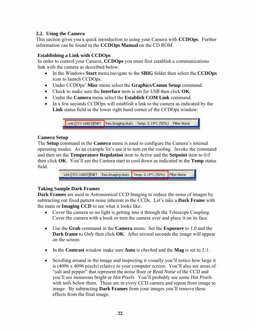
Establishing a Link with CCDOps In order to control your Camera, CCDOps you must first establish a communications link with the camera as described below:
• In the Windows Start menu navigate to the SBIG folder then select the CCDOpsicon to launch CCDOps.
• Under CCDOps’ Misc menu select the Graphics/Comm Setup command.• Check to make sure the Interface item is set for USB then click OK.• Under the Camera menu select the Establish COM Link command.• In a few seconds CCDOps will establish a link to the camera as indicated by the
Link status field in the lower right hand corner of the CCDOps window:
Camera Setup The Setup command in the Camera menu is used to configure the Camera’s internal operating modes. As an example let’s use it to turn on the cooling. Invoke the command and then set the Temperature Regulation item to Active and the Setpoint item to 0.0 then click OK. You’ll see the Camera start to cool down as indicated in the Temp status field.
Taking Sample Dark Frames Dark Frames are used in Astronomical CCD Imaging to reduce the noise of images by subtracting out fixed pattern noise inherent in the CCDs. Let’s take a Dark Frame with the main or Imaging CCD to see what it looks like:
• Cover the camera so no light is getting into it through the Telescope Coupling.Cover the camera with a book or turn the camera over and place it on its face.
• Use the Grab command in the Camera menu. Set the Exposure to 1.0 and theDark frame to Only then click OK. After several seconds the image will appearon the screen.
• In the Contrast window make sure Auto is checked and the Mag is set to 1:1.
• Scrolling around in the image and inspecting it visually you’ll notice how large itis (4096 x 4096 pixels) relative to your computer screen. You’ll also see areas of“salt and pepper” that represent the noise floor or Read Noise of the CCD andyou’ll see numerous bright or Hot Pixels. You’ll probably see some Hot Pixelswith tails below them. These are in every CCD camera and repeat from image toimage. By subtracting Dark Frames from your images you’ll remove theseeffects from the final image.
22
Let’s try taking a Dark Frame with the Tracking CCD to see how it’s different:
• In the Camera Setup command set the Active CCD to Tracking.
• Use the Grab command to take another Dark Frame.
• Visually inspect the image. First off you’ll notice it’s quite a bit smaller (640 x480 pixels). In addition to the effects noted in the Imaging CCD you’ll probablynotice a general brightening from top to bottom. This is typical for interlineCCDs like the Tracking CCD and again will repeat and subtract out of your finalimages.
Further Investigations At this point we refer you to the CCDOps Manual on the CD ROM for further learning about getting the most out of your STX CCD Camera. We also suggest you join the SBIG Group on Yahoo to learn from and interact with other users.
2.3. Specific Activities This section describes some of the unique features of the STX such as Ethernet control and Autoguiding.
Ethernet Configuration The STX allows communications to the PC with either USB or Ethernet. While USB offers faster image downloads Ethernet allows longer cable runs between the PC and the Camera, not being limited by the 15 foot USB cable length. The STX comes configured by the factory to have a fixed IP address of 192.168.0.100 but can be configured by CCDOps for other addresses or to use DHCP. Use the commands in the STX sub-menu of the Misc Menu to configure the STX. To Establish a link over Ethernet with CCDOps use the Graphics/Comm Setup command in the Misc menu and set the Interface to Ethernet and either fill in the Camera’s IP address or click the Detect button to search for it.
Web Browser The STX has an embedded web server built into it and can be controlled by your favorite Web Browser. This gives the STX support on all systems with the minimum requirement of a Web Browser. The factory default URL of the STX home page is:
http://192.168.0.100 If you’ve changed the Camera’s IP address or are using DHCP the URL will be based on the assigned IP address.
Making the Autoguiding Connection Like all SBIG cameras, the STX has an Autoguider port that can be connected to your Telescope. Use the supplied 6-pin phone-jack based Autoguider Cable to connect the STX to your Telescope.
23

2.4. Third Party Software The STX is compatible with many third party Astronomical Software packages. Several packages offer control of the STX and many others offer Image Processing of FITS Format Images acquired with the STX. This section describes several of those packages.
MaxIm DLDiffraction Limited in Ontario Canada has a popular Imaging program named MaximDl that works with the STX. You’ll need to be using Version 6 or later and make sure you have the latest SBIG Plug-In. whttp://diffractionlimited.com/product/maxim-dl/
Sky-X Camera Plug-inSoftware Bisque in Colorado makes a popular suite of Astronomical Software including a Planetarium program called The Sky. The optional camera plug-in can be found at their web site. For STX control please make sure you have the latest version. www.bisque.com
Support and Developer Resources The SBIG web site contains a wealth of Software Updates, Manuals, Application Notes, Drawings and Developer Resources for the STX and other SBIG products. www.sbig.com
24
Linux Software
CCDOpsLite for LinuxThis link downloads a zipped tar archive containing a Qt 3.3 project that allows to to acquire images from our Parallel and USB based cameras. It displays the images and allows saving them in SBIG and FITS formats. In addition you can open images saved in SBIG Format. We offer this as a starting point for the adventurous.
Justin Pryzby’s ST7CtlApplication for acquiring images from SBIG cameras supported under Linux.
Filip Hroch’s NightViewNightView is a software package to control SBIG’s CCD cameras under Linux. This software allows full control of a camera and a filter wheel. It can be used for either interactive or a batch processing. It fully replaces the commercial SBIG utilities.
Sky-X Linux camera plug-in
Appendix A – Adjustments and Maintenance This section describes the various adjustments and maintenance issues with the STX.
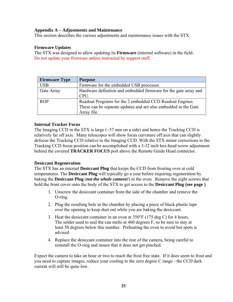
Firmware Updates The STX was designed to allow updating its Firmware (internal software) in the field. Do not update your firmware unless instructed by support staff.
Firmware Type Purpose USB Firmware for the embedded USB processor. Gate Array Hardware definition and embedded firmware for the gate array and
CPU. ROP Readout Programs for the 2 embedded CCD Readout Engines.
These can be separate updates and are also embedded in the Gate Array file.
Internal Tracker Focus The Imaging CCD in the STX is large (~37 mm on a side) and hence the Tracking CCD is relatively far off axis. Many telescopes will show focus curvature off axis that can slightly defocus the Tracking CCD relative to the Imaging CCD. With the STX minor corrections to the Tracking CCD focus position can be accomplished with a 3-32 inch hex-head screw adjustment behind the covered TRACKER FOCUS port above the Remote Guide Head connector.
Desiccant Regeneration The STX has an internal Desiccant Plug that keeps the CCD from frosting over at cold temperatures. The Desiccant Plug will typically go a year before requiring regeneration by baking the Desiccant Plug (not the whole camera!) in the oven. Remove the eight screws that hold the front cover onto the body of the STX to get access to the Desiccant Plug (see page )
1. Unscrew the desiccant container from the side of the chamber and remove theO-ring.
2. Plug the resulting hole in the chamber by placing a piece of black plastic tapeover the opening to keep dust out while you are baking the desiccant.
3. Heat the desiccant container in an oven at 350°F (175 deg C) for 4 hours.The solder used to seal the can melts at 460 degrees F, so be sure to stay atleast 50 degrees below this number. Preheating the oven to avoid hot spots isadvised.
4. Replace the desiccant container into the rear of the camera, being careful toreinstall the O-ring and insure that it does not get pinched.
Expect the camera to take an hour or two to reach the frost free state. If it does seem to frost and you need to capture images, reduce your cooling to the zero degree C range - the CCD dark current will still be quite low.
25
Cleaning the CCD and the Window
The design of SBIG cameras allows for cleaning of the CCD. The optical heads are not evacuated and are quite easy to open and clean. When opening the CCD chamber, one should be very careful not to damage the structures contained inside. To open the CCD Chamber, remove the six screws that hold the 5 inch front cover in place. Remove the six screws and lift the front cover, exposing the structures inside. There is a rubber O-Ring that sets in the groove on the top of the Chamber housing. The CCD array is protected by a thin cover glass that can be cleaned with Q-Tips and Isopropyl Alcohol. Do not get alcohol on the shutter. Dust on the CCD should be blown off. Use alcohol only if necessary. The optical window of the chamber housing can be cleaned the same way. When reinstalling the chamber housing, be very careful to make sure the O-ring is in the groove when seated.
26
Appendix B - Capturing a Good Flat Field This appendix describes how to take a simple flat field. A good flat field is essential for displaying features little brighter than the sky background. The flat field corrects for pixel non-uniformity, vignetting, dust spots (affectionately called dust doughnuts), and stray light variations. If the flat field is not good it usually shows up as a variation in sky brightness from on side of the frame to the other.
B-1. TechniqueThe first consideration in capturing a flat field is to use the telescope-CCD combination in exactly the configuration used to collect the image. This means you probably have to capture the flat field at the telescope. Do not rotate the head between image and flat field, since the vignetting is usually slightly off center. Do not be tempted to build a little LED into the telescope or camera for doing flat fields; it doesn't work at all. The dust debris shadows would be different!
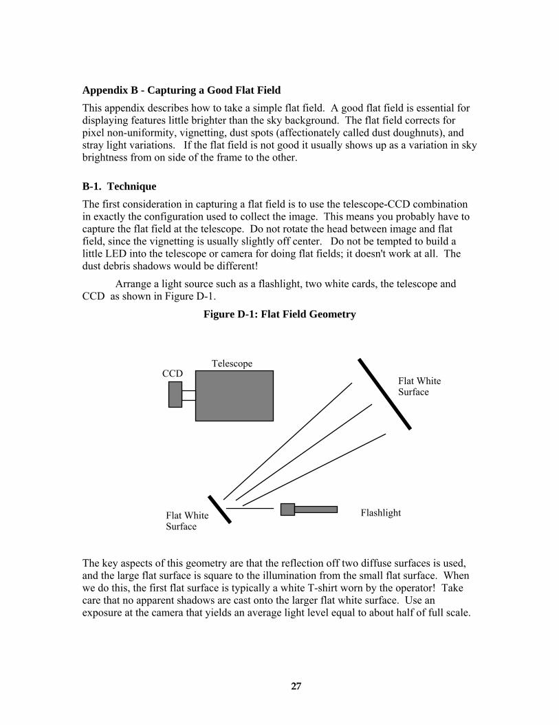
Arrange a light source such as a flashlight, two white cards, the telescope and CCD as shown in Figure D-1.
Figure D-1: Flat Field Geometry
Flashlight
Flat White Surface
Flat White Surface
TelescopeCCD
The key aspects of this geometry are that the reflection off two diffuse surfaces is used, and the large flat surface is square to the illumination from the small flat surface. When we do this, the first flat surface is typically a white T-shirt worn by the operator! Take care that no apparent shadows are cast onto the larger flat white surface. Use an exposure at the camera that yields an average light level equal to about half of full scale.
27
Appendix C – Camera Specifications
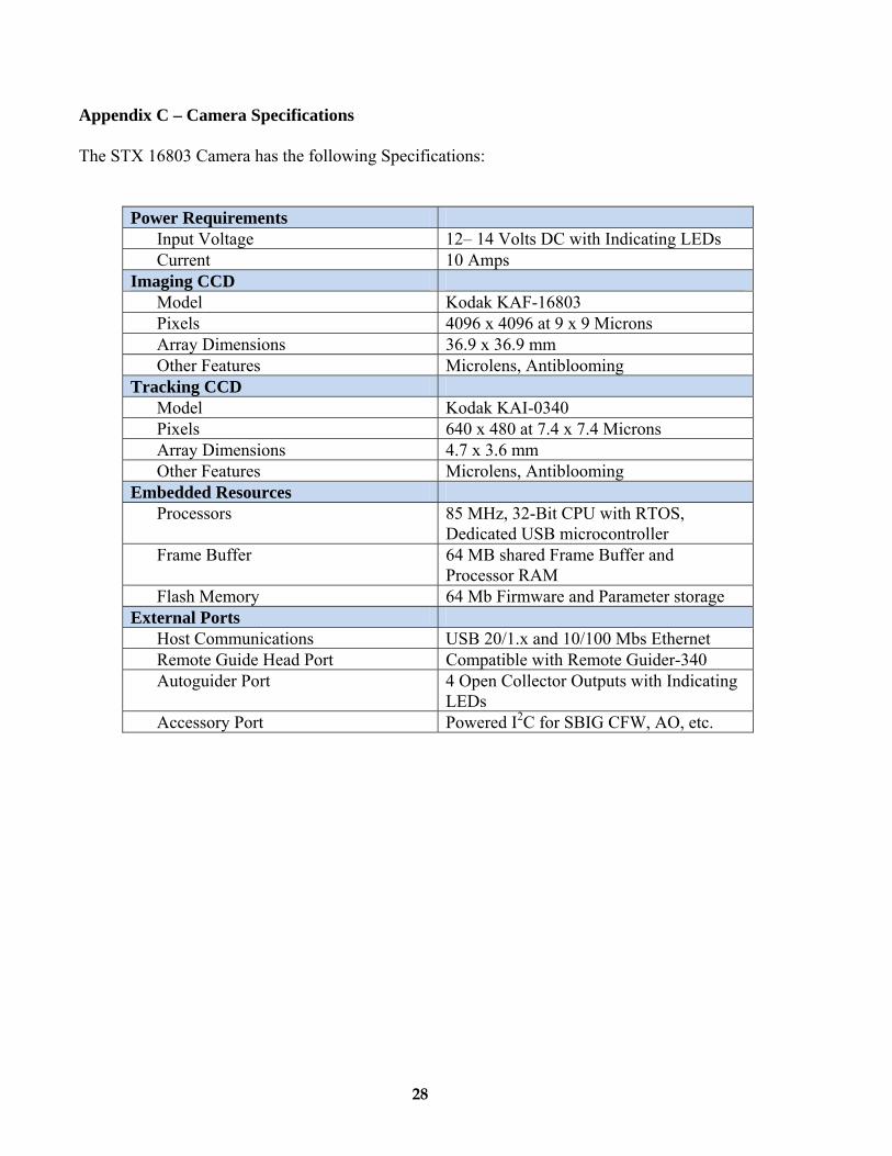
The STX 16803 Camera has the following Specifications:
Power Requirements Input Voltage 12– 14 Volts DC with Indicating LEDs Current 10 Amps
Imaging CCD Model Kodak KAF-16803Pixels 4096 x 4096 at 9 x 9 Microns Array Dimensions 36.9 x 36.9 mm Other Features Microlens, Antiblooming
Tracking CCD Model Kodak KAI-0340Pixels 640 x 480 at 7.4 x 7.4 Microns Array Dimensions 4.7 x 3.6 mm Other Features Microlens, Antiblooming
Embedded Resources Processors 85 MHz, 32-Bit CPU with RTOS,
Dedicated USB microcontroller Frame Buffer 64 MB shared Frame Buffer and
Processor RAM Flash Memory 64 Mb Firmware and Parameter storage
External Ports Host Communications USB 20/1.x and 10/100 Mbs Ethernet Remote Guide Head Port Compatible with Remote Guider-340 Autoguider Port 4 Open Collector Outputs with Indicating
LEDs Accessory Port Powered I2C for SBIG CFW, AO, etc.
28

Appendix D – Connector and Cables
Power Jack The Power Jack has the following pinouts:
Pin Function Shell Earth/Chassis Ground 1,5,6 +12V, 10A2,3,4 DC Return
Scope Port The Scope Port is used for autoguiding your telescope and has the following pinouts:
I2C/AUX Port The I2C/AUX Port is for connecting accessories to your STX and has the following pinouts:
Pin Function Pin Function 1 No connect 6 Trigger In 2 Open Collector
Trigger Out 7 Open Collector
Genl. Purp. Out 3 Serial Clock 8 +12V Raw4 Serial Data 9 +3.3V5 Signal Ground Shell Chassis Ground
29
30
Recommended