Computer Architecture II
1
Computer architecture II
Network topologies
Computer Architecture II
2
Plan for todayScalable interconnection networks
Basic concepts, definitions Topologies Switching Routing Performance
Computer Architecture II
3
Outline
•Basic concepts, definitions
•Topologies
•Switching
•Routing
•Performance
Computer Architecture II
4
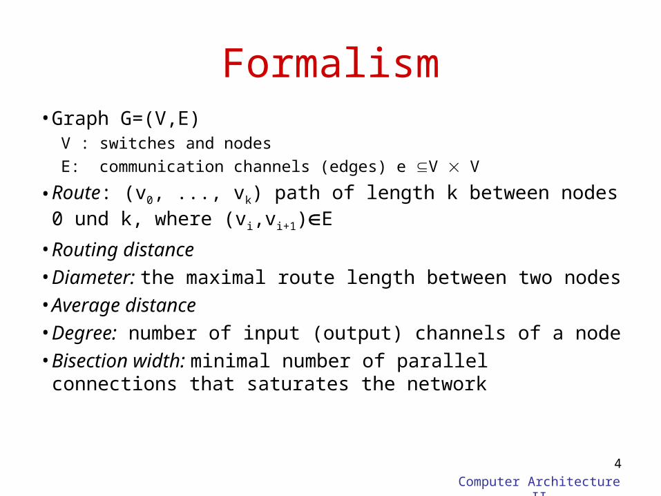
Formalism• Graph G=(V,E)
V : switches and nodes
E: communication channels (edges) e V V
• Route: (v0, ..., vk) path of length k between nodes 0 und k, where (vi,vi+1)E
• Routing distance• Diameter: the maximal route length between two nodes• Average distance• Degree: number of input (output) channels of a node• Bisection width: minimal number of parallel connections
that saturates the network
Computer Architecture II
5
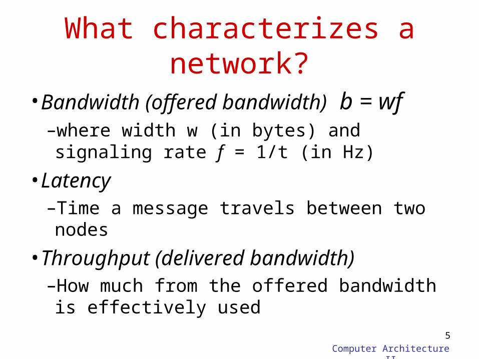
What characterizes a network?
•Bandwidth (offered bandwidth) b = wf–where width w (in bytes) and signaling rate f = 1/t (in Hz)
•Latency–Time a message travels between two nodes
•Throughput (delivered bandwidth) –How much from the offered bandwidth is effectively used
Computer Architecture II
6
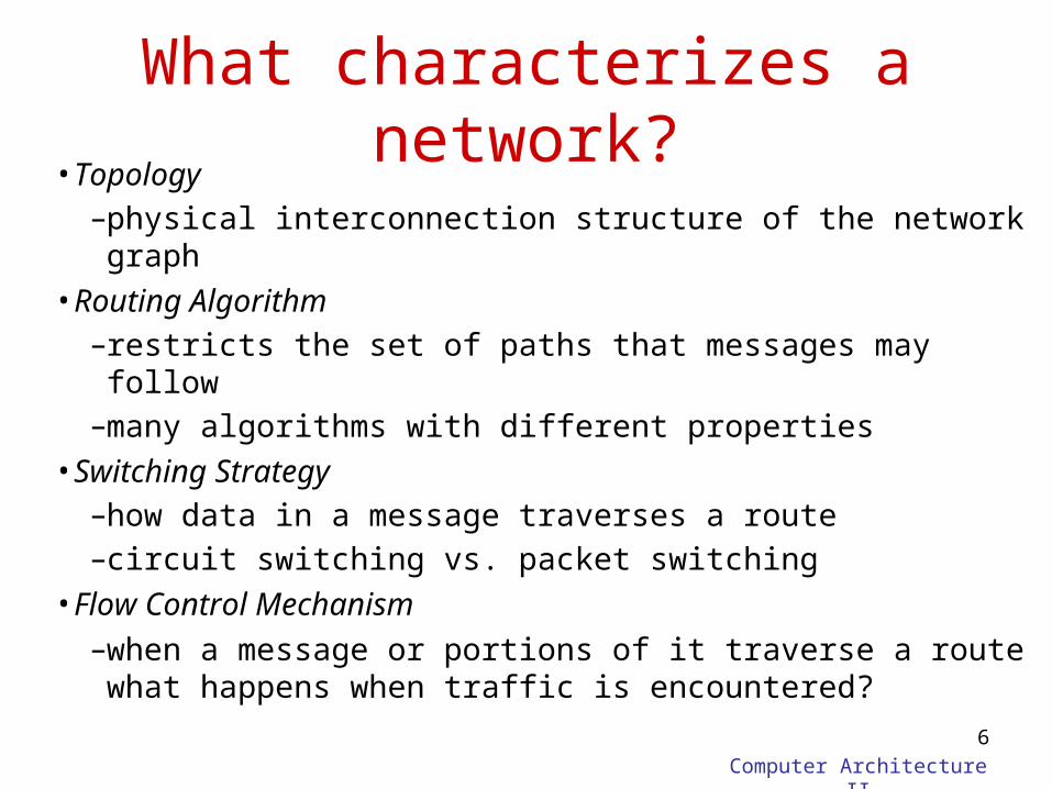
What characterizes a network?• Topology
–physical interconnection structure of the network graph• Routing Algorithm
–restricts the set of paths that messages may follow–many algorithms with different properties
• Switching Strategy –how data in a message traverses a route–circuit switching vs. packet switching
• Flow Control Mechanism–when a message or portions of it traverse a route what
happens when traffic is encountered?
Computer Architecture II
7
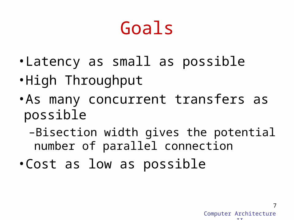
Goals
•Latency as small as possible
•High Throughput
•As many concurrent transfers as possible–Bisection width gives the potential number of parallel connection
•Cost as low as possible
Computer Architecture II
8
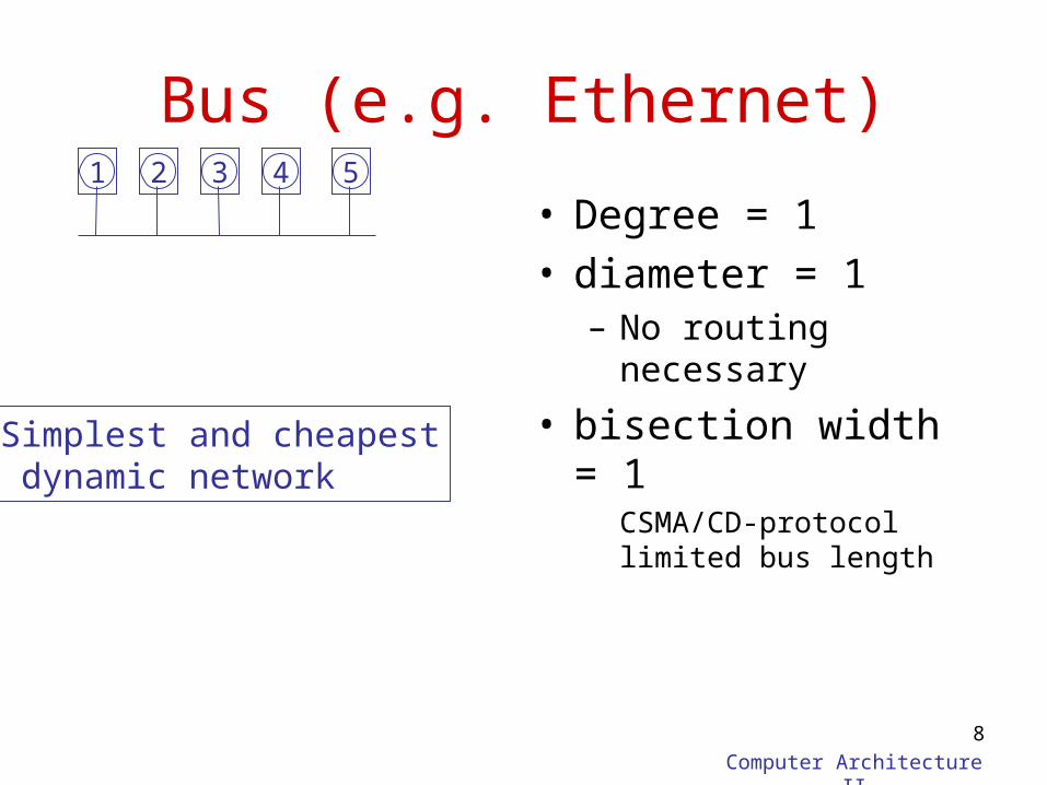
Bus (e.g. Ethernet)
• Degree = 1• diameter = 1
– No routing necessary
• bisection width = 1CSMA/CD-protocol limited bus length
1 2 3 4 5
Simplest and cheapest dynamic network
Computer Architecture II
9
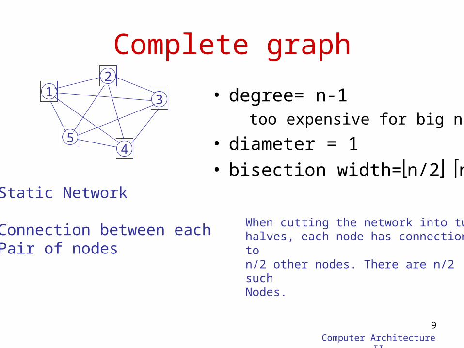
Complete graph
• degree= n-1too expensive for big nets
• diameter = 1• bisection width=n/2n/2
12
3
45
Static Network
Connection between each Pair of nodes
When cutting the network into two halves, each node has connection to n/2 other nodes. There are n/2 such Nodes.
Computer Architecture II
10
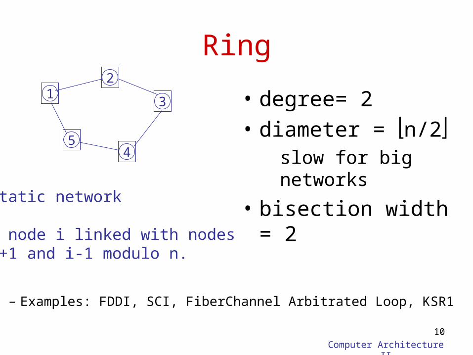
Ring
• degree= 2
• diameter = n/2slow for big networks
• bisection width = 2
12
3
45
Static network
A node i linked with nodesi+1 and i-1 modulo n.
– Examples: FDDI, SCI, FiberChannel Arbitrated Loop, KSR1
Computer Architecture II
11
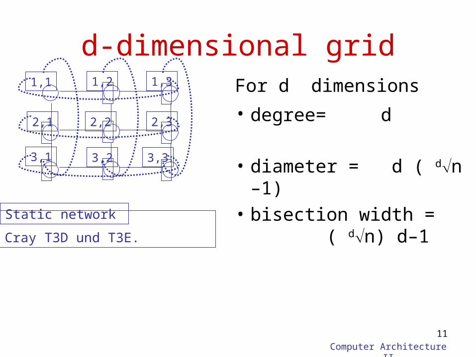
For d dimensions
• degree= d
• diameter = d ( dn –1)
• bisection width = ( dn) d–1
d-dimensional grid1,1 1,2 1,3
2,1 2,2 2,3
3,1 3,2 3,3
Cray T3D und T3E.
Static network
Computer Architecture II
12
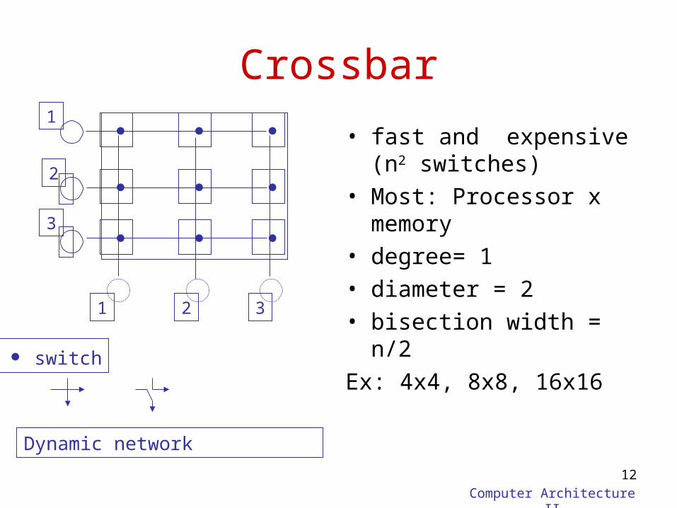
Crossbar
• fast and expensive (n2 switches)
• Most: Processor x memory
• degree= 1• diameter = 2• bisection width = n/2
Ex: 4x4, 8x8, 16x16
1
1
2
3
Dynamic network
2 3
switch
Computer Architecture II
13
0011
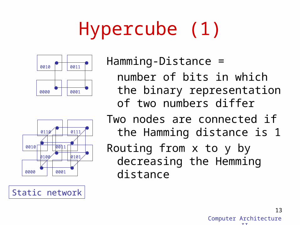
Hypercube (1)
Hamming-Distance =
number of bits in which the binary representation of two numbers differ
Two nodes are connected if the Hamming distance is 1
Routing from x to y by decreasing the Hemming distance
0000 0001
0010
0000 0001
0011 0010 0100 0101
0111 0110
Static network
Computer Architecture II
14
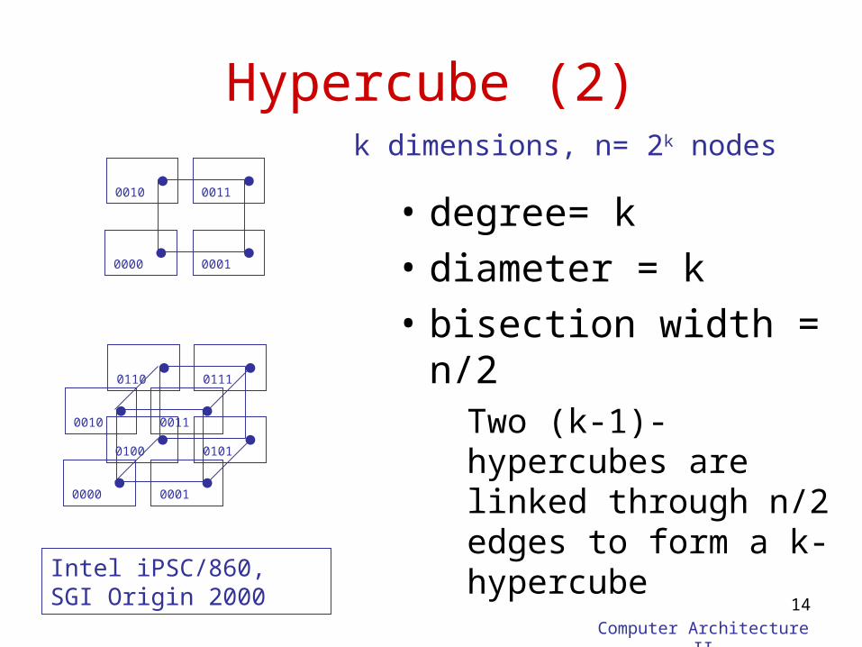
Hypercube (2)
• degree= k
• diameter = k
• bisection width = n/2Two (k-1)-hypercubes are linked through n/2 edges to form a k-hypercube
0000 0001
0011 0010
0000 0001
0011 0010 0100 0101
0111 0110
Intel iPSC/860, SGI Origin 2000
k dimensions, n= 2k nodes
Computer Architecture II
15
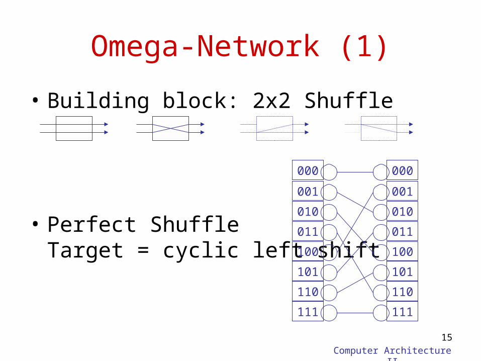
• Building block: 2x2 Shuffle
• Perfect Shuffle Target = cyclic left shift
Omega-Network (1)
000
001
010
011
100
101
110
111
000
001
010
011
100
101
110
111
Computer Architecture II
16
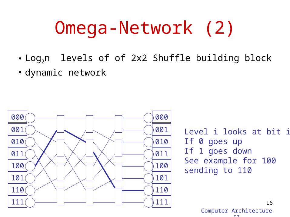
Omega-Network (2)
• Log2n levels of of 2x2 Shuffle building block
• dynamic network
Level i looks at bit iIf 0 goes upIf 1 goes downSee example for 100sending to 110
000
001
010
011
100
101
110
111
000
001
010
011
100
101
110
111
Computer Architecture II
17
Omega-Network (3)
n nodes, (n/2) log2n building blocks
• degree= 2 for nodes, 4 for building blocks
• diameter = log2n
• bisection width = n/2 – for a random permutation, n/2 messages are
expected to cross the network in parallel– Extremes
• If all the nodes want to send to 0, only one message in parallel
• If each sends a message to himself n messages in parallel
Computer Architecture II
18
Fat Tree /Clos-Network (1)
• Nodes = leaves of a tree
• Tree has the diameter 2log2n
„von farthest left over the root to farthest right"
• Simple tree has bisection width = 1bottleneck
• Fat Tree: – Edges at level i have double capacity as edges at level i-1– At level i expensive switches with 2i inputs and 2i outputs – Known as Clos-networks
Computer Architecture II
19
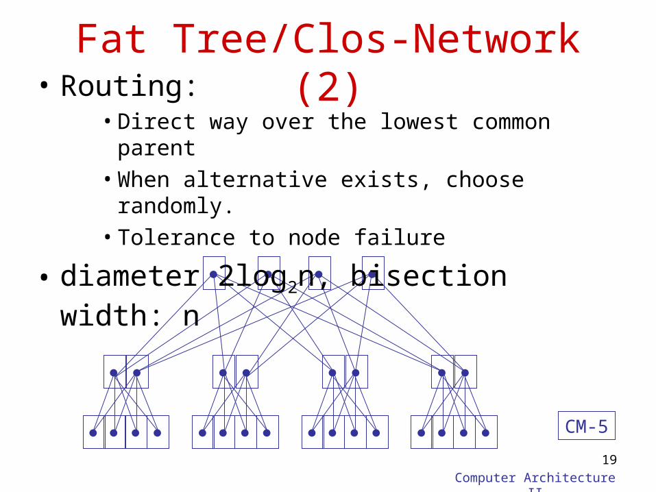
Fat Tree/Clos-Network (2)
• Routing:• Direct way over the lowest common parent• When alternative exists, choose randomly.• Tolerance to node failure
• diameter 2log2n, bisection width: n
CM-5
Computer Architecture II
20
Switching
• How a message traverses the network from one node to the other
• Circuit switching– One path from source to destination established – All packets will take that way– Like the telephone system
• Packet switching– A message broken into a sequence of packets which
can be sent across different routes– Better utilization of network resources
Packet Routing
• There are two basic approaches to routing packets, based on what a switch does when the packet begins arriving
1) Store-and-forward
2) Cut-through– Virtual cut-through– Wormhole
Computer Architecture II
22
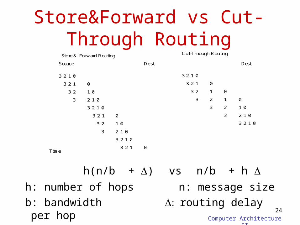
Packet routing: Store-and-Forward
• A packet is completely stored at a switch before being forwarded
• The packet is always on at least two nodes• Pb: Switches need lots of memory for storing the
incoming packets• Switching takes place step-by-step, the blocking
danger is small
Computer Architecture II
23
Packet routing: Cut through
• A packet may come partially into the switch and leave its tail on other nodes– It may reside on more than 2 switches
• The decision to forward the packet may be taken right away
• What to do with the rest of the packet if the head blocks?– Cut-through: gather tail where the head is
• It degenerates into store-and-forward for high contention
– Wormhole: If the head blocks the whole “worm” blocks
Computer Architecture II
24
Store&Forward vs Cut-Through Routing
h(n/b + ) vs n/b + h h: number of hops n: message size
b: bandwidth routing delay per hop
23 1 0
23 1 0
23 1 0
23 1 0
23 1 0
23 1 0
23 1 0
23 1 0
23 1 0
23 1 0
23 1 0
23 1
023
3 1 0
2 1 0
23 1 0
0
1
2
3
23 1 0Time
Store & Forward Routing Cut-Through Routing
Source Dest Dest
Routing Algorithm
• How do I know where a packet should go?– Topology does NOT determine routing
• Routing algorithms
1) Arithmetic
2) Source-based
3) Table lookup
4) Adaptive—route based on network state (e.g., contention)
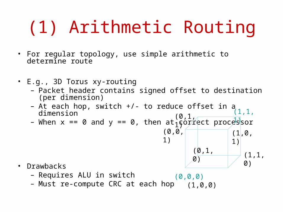
(1) Arithmetic Routing• For regular topology, use simple arithmetic to determine route
• E.g., 3D Torus xy-routing– Packet header contains signed offset to destination (per
dimension)– At each hop, switch +/- to reduce offset in a dimension– When x == 0 and y == 0, then at correct processor
• Drawbacks– Requires ALU in switch– Must re-compute CRC at each hop
(0,0,0) (1,0,0)
(0,0,1) (1,0,1)
(0,1,1)(1,1,1)
(0,1,0)(1,1,0)
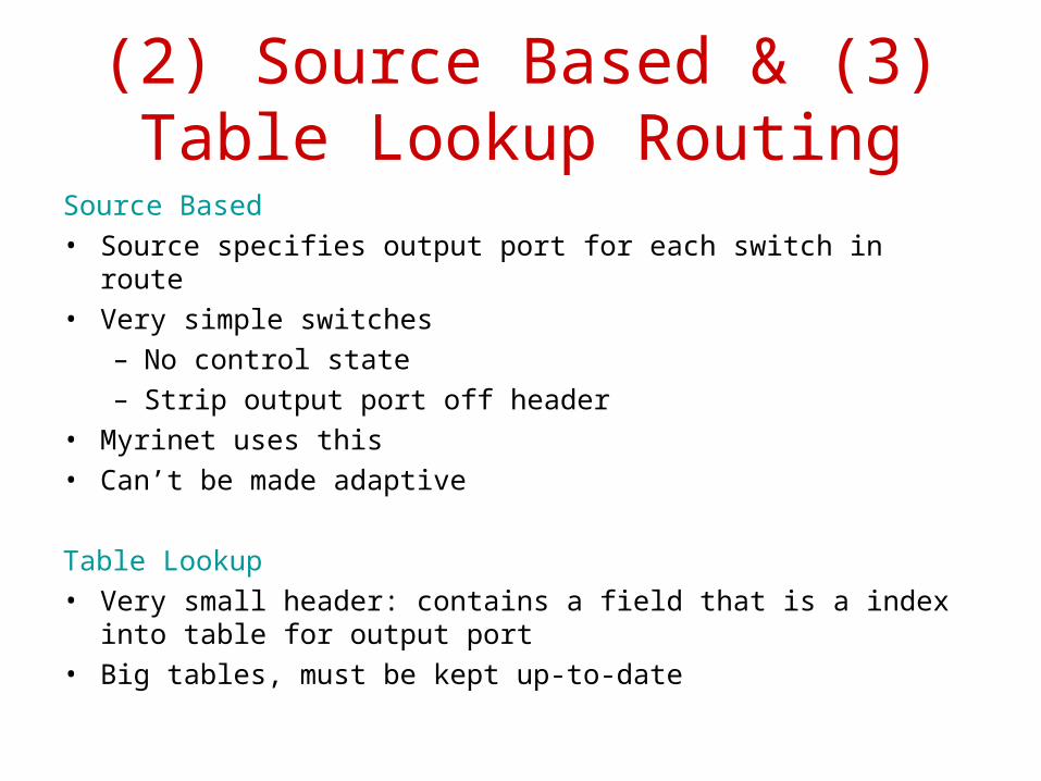
(2) Source Based & (3) Table Lookup Routing
Source Based• Source specifies output port for each switch in route• Very simple switches
– No control state– Strip output port off header
• Myrinet uses this• Can’t be made adaptive
Table Lookup• Very small header: contains a field that is a index into table for
output port• Big tables, must be kept up-to-date
001
000
101
100
010 110
111011
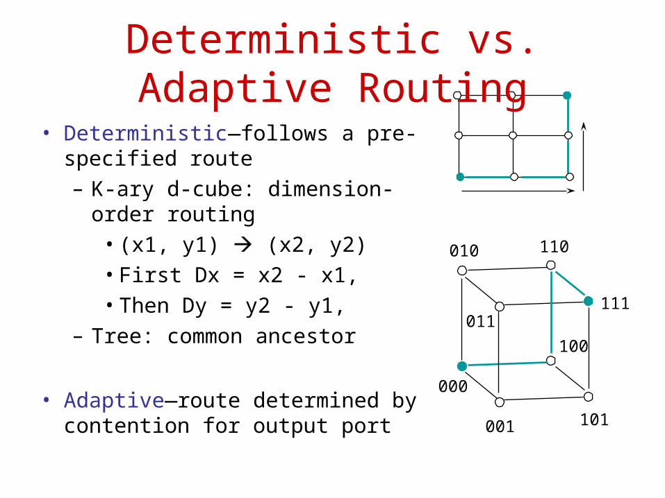
Deterministic vs. Adaptive Routing
• Deterministic—follows a pre-specified route– K-ary d-cube: dimension-order
routing• (x1, y1) (x2, y2)• First Dx = x2 - x1,• Then Dy = y2 - y1,
– Tree: common ancestor
• Adaptive—route determined by contention for output port
Computer Architecture II
29
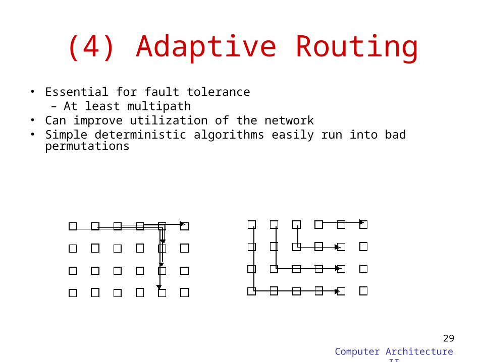
(4) Adaptive Routing• Essential for fault tolerance
– At least multipath• Can improve utilization of the network• Simple deterministic algorithms easily run into bad permutations
Computer Architecture II
30
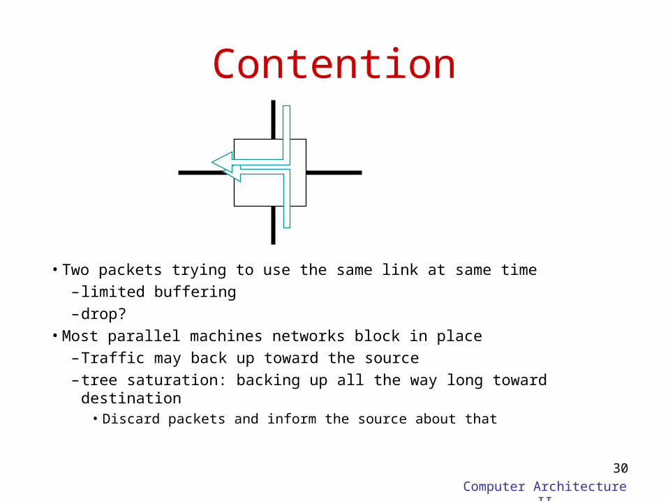
Contention
• Two packets trying to use the same link at same time– limited buffering–drop?
• Most parallel machines networks block in place–Traffic may back up toward the source– tree saturation: backing up all the way long toward destination
• Discard packets and inform the source about that
Computer Architecture II
31
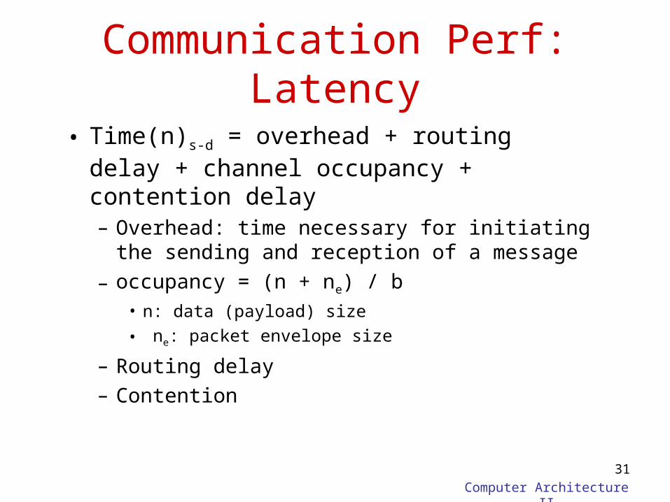
Communication Perf: Latency
• Time(n)s-d = overhead + routing delay + channel occupancy + contention delay– Overhead: time necessary for initiating the
sending and reception of a message
– occupancy = (n + ne) / b• n: data (payload) size
• ne: packet envelope size
– Routing delay– Contention
Computer Architecture II
32
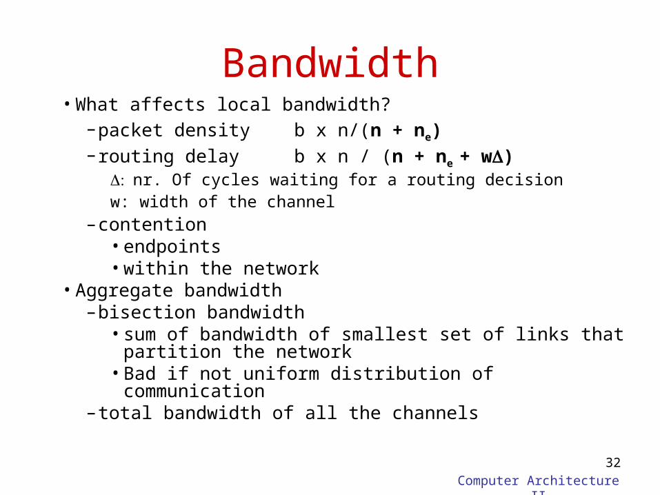
Bandwidth• What affects local bandwidth?
–packet density b x n/(n + ne)–routing delay b x n / (n + ne + w)
nr. Of cycles waiting for a routing decisionw: width of the channel
–contention• endpoints• within the network
• Aggregate bandwidth–bisection bandwidth
• sum of bandwidth of smallest set of links that partition the network
• Bad if not uniform distribution of communication–total bandwidth of all the channels
Computer Architecture II
33
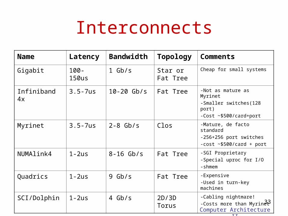
Interconnects
Name Latency Bandwidth Topology Comments
Gigabit 100-150us 1 Gb/s Star or Fat Tree
Cheap for small systems
Infiniband 4x 3.5-7us 10-20 Gb/s Fat Tree -Not as mature as Myrinet
-Smaller switches(128 port)
-Cost ~$500/card+port
Myrinet 3.5-7us 2-8 Gb/s Clos -Mature, de facto standard
-256+256 port switches
-cost ~$500/card + port
NUMAlink4 1-2us 8-16 Gb/s Fat Tree -SGI Proprietary
-Special uproc for I/O
-shmem
Quadrics 1-2us 9 Gb/s Fat Tree -Expensive
-Used in turn-key machines
SCI/Dolphin 1-2us 4 Gb/s 2D/3D Torus -Cabling nightmare!
-Costs more than Myrinet
Computer Architecture II
34
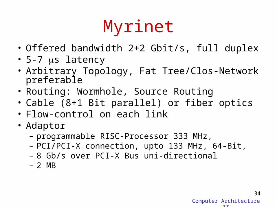
Myrinet• Offered bandwidth 2+2 Gbit/s, full duplex• 5-7 s latency• Arbitrary Topology, Fat Tree/Clos-Network
preferable• Routing: Wormhole, Source Routing• Cable (8+1 Bit parallel) or fiber optics• Flow-control on each link• Adaptor
– programmable RISC-Processor 333 MHz,– PCI/PCI-X connection, upto 133 MHz, 64-Bit,– 8 Gb/s over PCI-X Bus uni-directional– 2 MB
Computer Architecture II
35
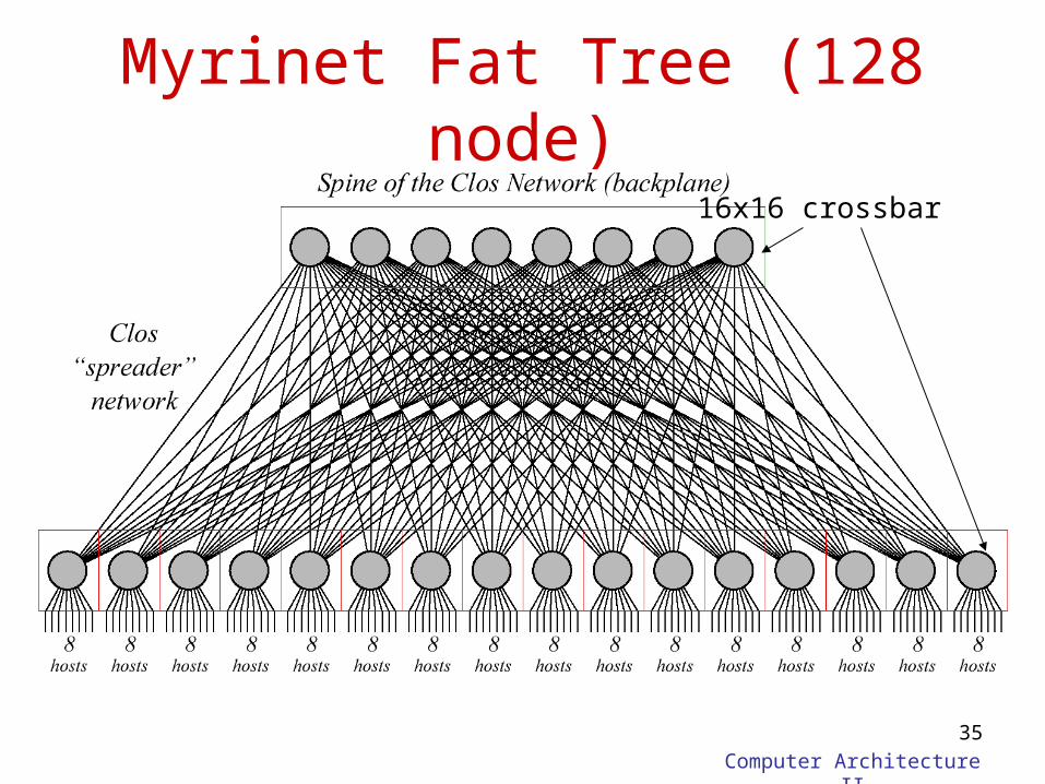
Myrinet Fat Tree (128 node)
16x16 crossbar
Computer Architecture II
36
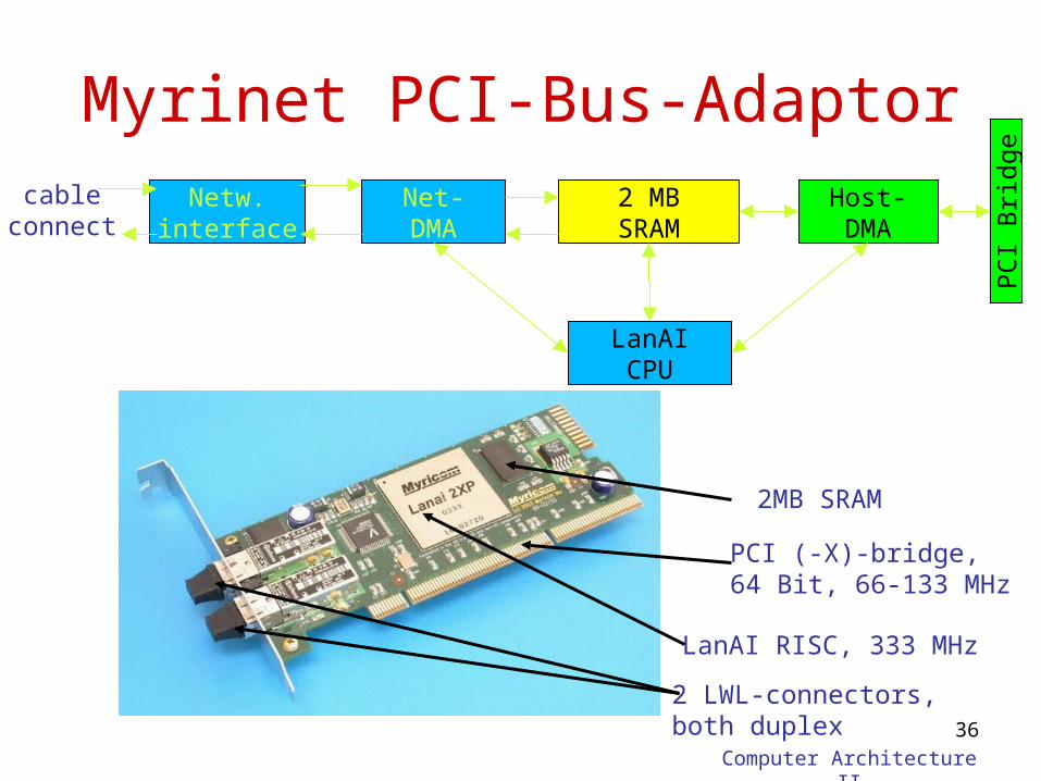
Myrinet PCI-Bus-AdaptorNetw.
interface2 MBSRAM
Host-DMA
PC
I B
ridg
e
Net-DMA
LanAICPU
cableconnect
PCI (-X)-bridge,64 Bit, 66-133 MHz
LanAI RISC, 333 MHz
2 LWL-connectors, both duplex
2MB SRAM
Computer Architecture II
37
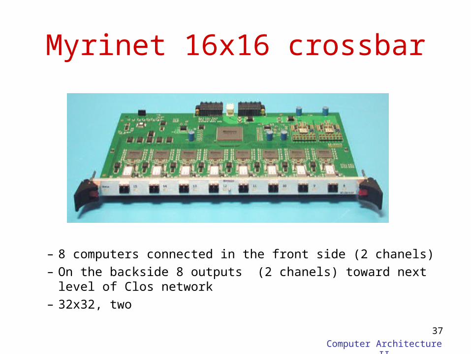
Myrinet 16x16 crossbar
– 8 computers connected in the front side (2 chanels)– On the backside 8 outputs (2 chanels) toward next level of
Clos network– 32x32, two
Computer Architecture II
38
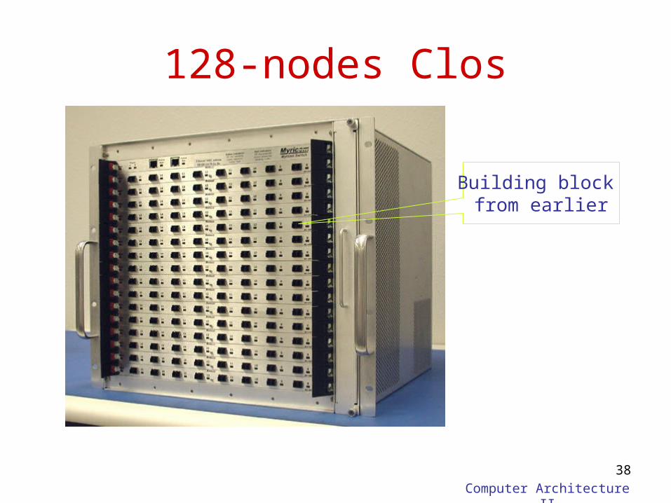
128-nodes Clos
Building block from earlier
Computer Architecture II
39
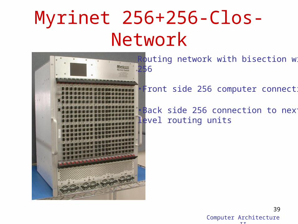
Myrinet 256+256-Clos-Network
Routing network with bisection width256
•Front side 256 computer connection
•Back side 256 connection to next level routing units
Computer Architecture II
40
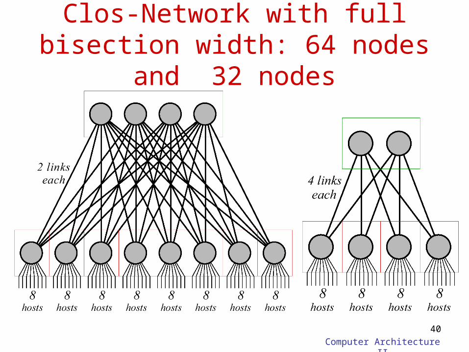
Clos-Network with full bisection width: 64 nodes and 32 nodes
Recommended