© Panasonic Electric Works Co., Ltd. 2011.All rights reserved. Unauthorized copying and distri-bution is a violation of law.
Order Number PTD1103X35CE
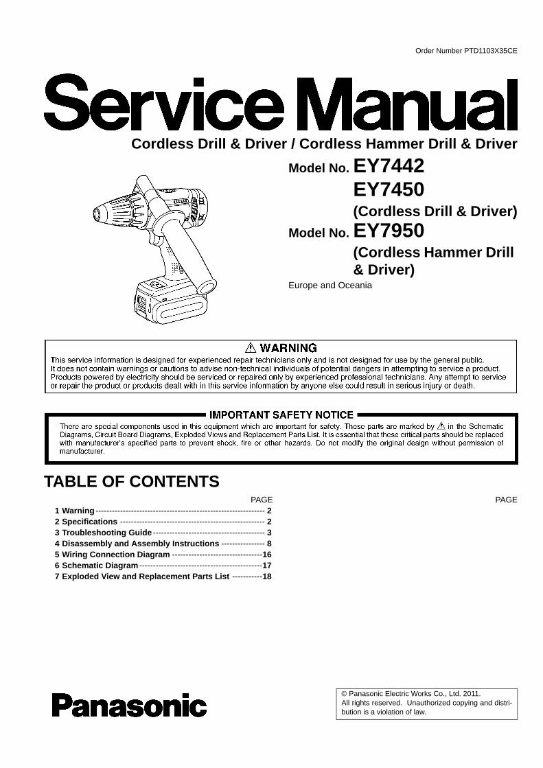
Cordless Drill & Driver / Cordless Hammer Drill & DriverModel No. EY7442
EY7450(Cordless Drill & Driver)
Model No. EY7950(Cordless Hammer Drill & Driver)
Europe and Oceania
TABLE OF CONTENTSPAGE PAGE
1 Warning -------------------------------------------------------------- 22 Specifications ----------------------------------------------------- 23 Troubleshooting Guide ----------------------------------------- 34 Disassembly and Assembly Instructions ---------------- 85 Wiring Connection Diagram ---------------------------------166 Schematic Diagram ---------------------------------------------177 Exploded View and Replacement Parts List -----------18
2
1 WarningCaution:
• Pb free solder has a higher melting point that standard solder; Typical the melting point is 50 - 70°F (30 - 40°C) higher. Pleaseuse a soldering iron with temperature control and adjust it to 750 ± 20°F (400 ± 10°C). In case of using high temperature solder-ing iron, please be careful not to heat too long.
• Pb free solder will tend to splash when heated too high (about 1100°F / 600°C).
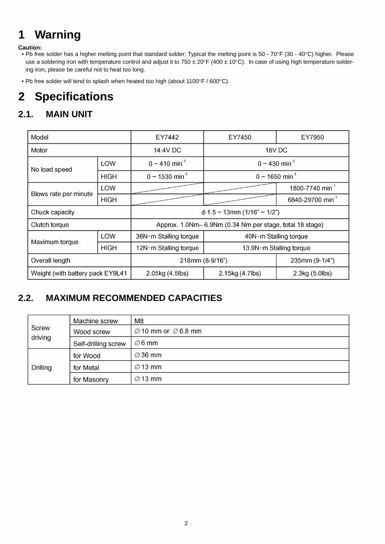
2 Specifications2.1. MAIN UNIT
2.2. MAXIMUM RECOMMENDED CAPACITIES
3
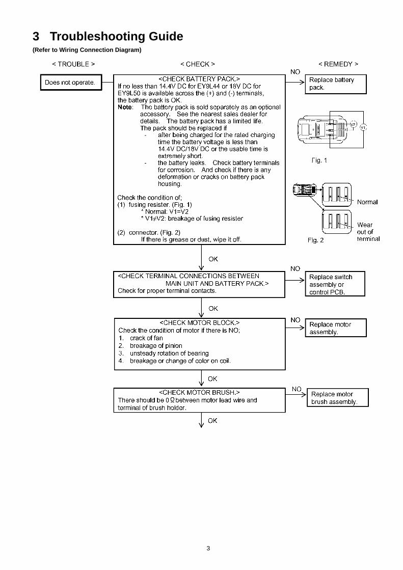
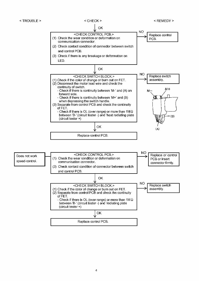
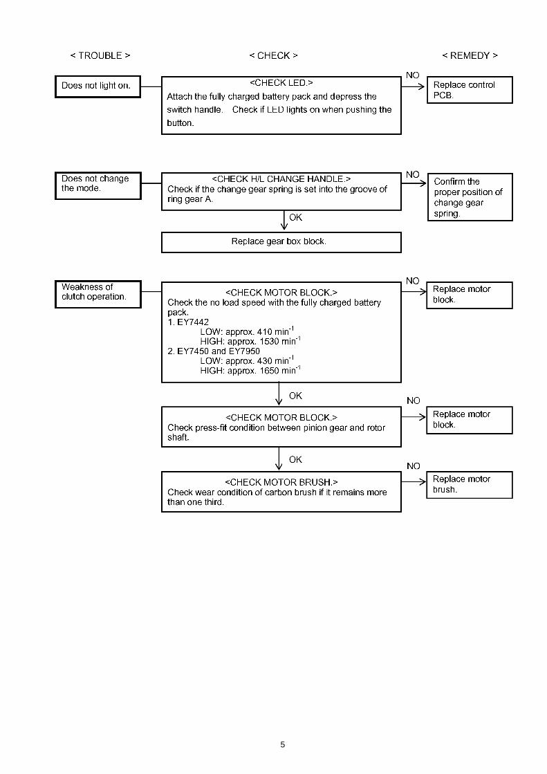
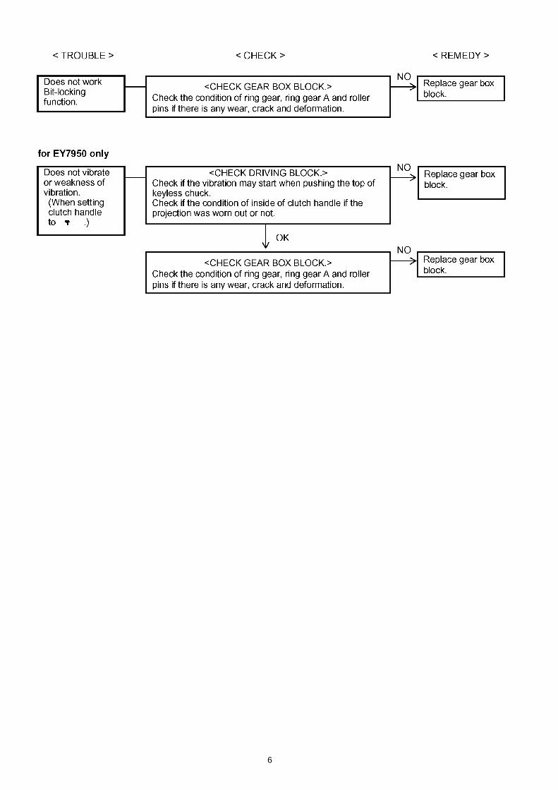
3 Troubleshooting Guide(Refer to Wiring Connection Diagram)
4
5
6
7
3.1. Trial Operation (after checking Troubleshooting Guide.)3.1.1. ASSEMBLY
1. Confirm if there is NO gap between Housing A and B by pinching the lead wires.2. Confirm all screws are tightened firmly.3. There should be no metallic sound and abnormal sound.4. There is no dust or deformation on battery terminals.5. Confirm if there is no dirt when repairing.
3.1.2. OPERATION1. Confirm the forward and reverse side of rotation.2. Confirm if LED rights ON. Once battery pack is removed and attached, press the switch handle, otherwise LED does not right
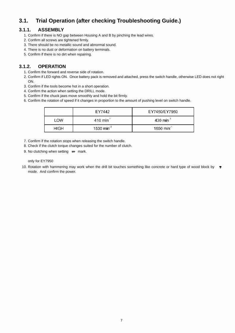
ON.3. Confirm if the tools become hot in a short operation.4. Confirm the action when setting the DRILL mode.5. Confirm if the chuck jaws move smoothly and hold the bit firmly.6. Confirm the rotation of speed if it changes in proportion to the amount of pushing level on switch handle.
7. Confirm if the rotation stops when releasing the switch handle.8. Check if the clutch torque changes suited for the number of clutch.9. No clutching when setting mark.
only for EY795010. Rotation with hammering may work when the drill bit touches something like concrete or hard type of wood block by
mode. And confirm the power.
8
4 Disassembly and Assembly Instructions
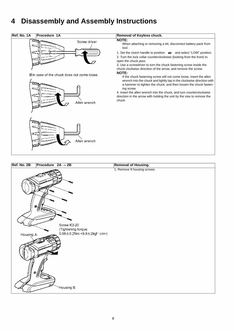
Ref. No. 1A Procedure 1A Removal of Keyless chuck.NOTE:
When attaching or removing a bit, disconnect battery pack from tool.
1. Set the clutch handle to position and select “LOW” position.2. Turn the lock collar counterclockwise (looking from the front) to open the chuck jaws.3. Use a screwdriver to turn the chuck fastening screw inside the chuck clockwise direction of the arrow, and remove the screw.NOTE:
If the chuck fastening screw will not come loose, insert the allen wrench into the chuck and lightly tap in the clockwise direction with a hammer to tighten the chuck, and then loosen the chuck fasten-ing screw.
4. Insert the allen wrench into the chuck, and turn counterclockwise direction in the arrow with holding the unit by the vise to remove the chuck.
Ref. No. 2B Procedure 2A → 2B Removal of Housing.1. Remove 9 housing screws.
9
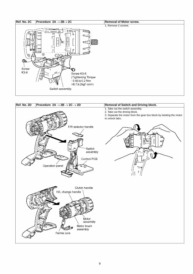
Ref. No. 2C Procedure 2A → 2B→ 2C Removal of Motor screw.1. Remove 2 screws.
Ref. No. 2D Procedure 2A → 2B → 2C → 2D Removal of Switch and Driving block.1. Take out the switch assembly.2. Take out the driving block.3. Separate the motor from the gear box block by twisting the motor to unlock tabs.
10
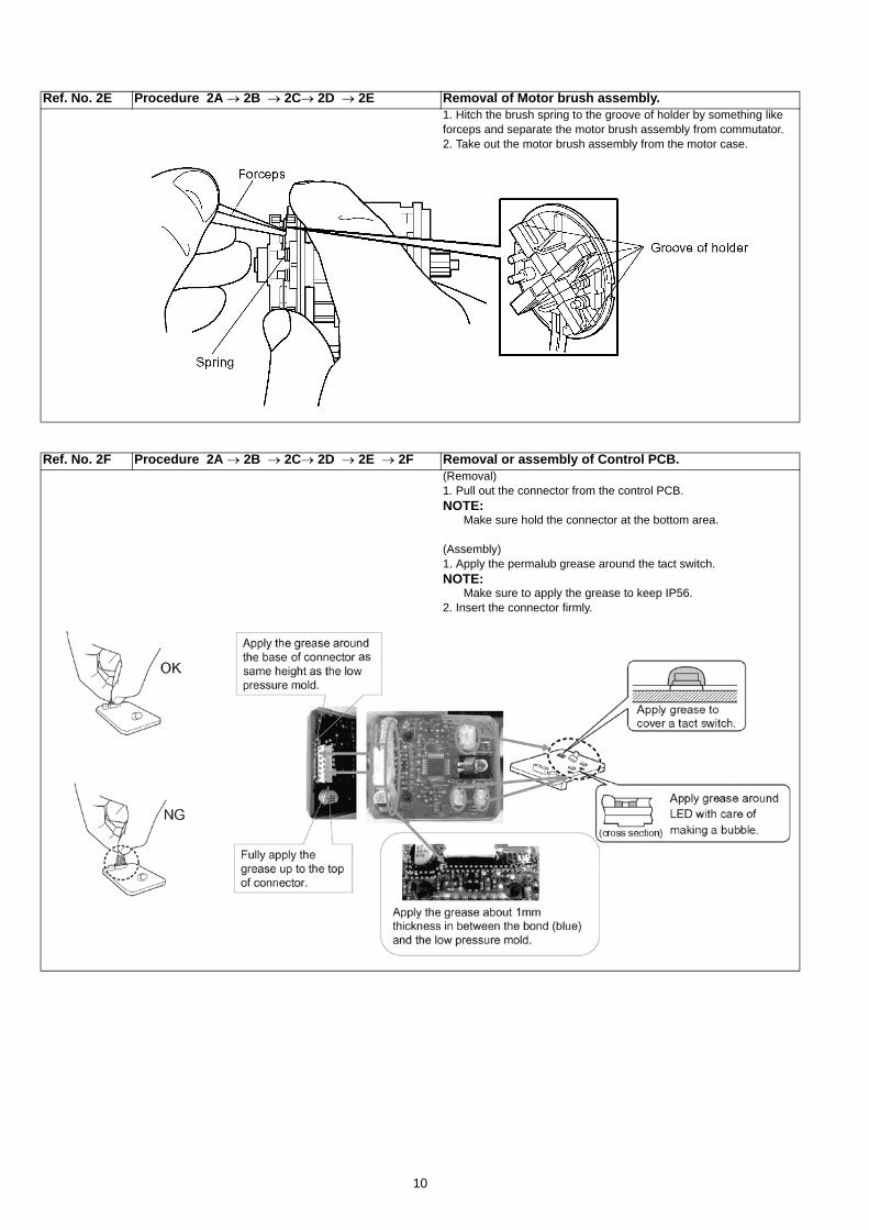
Ref. No. 2E Procedure 2A → 2B → 2C→ 2D → 2E Removal of Motor brush assembly.1. Hitch the brush spring to the groove of holder by something like forceps and separate the motor brush assembly from commutator.2. Take out the motor brush assembly from the motor case.
Ref. No. 2F Procedure 2A → 2B → 2C→ 2D → 2E → 2F Removal or assembly of Control PCB.(Removal)1. Pull out the connector from the control PCB.NOTE:
Make sure hold the connector at the bottom area.
(Assembly)1. Apply the permalub grease around the tact switch.NOTE:
Make sure to apply the grease to keep IP56.2. Insert the connector firmly.
11
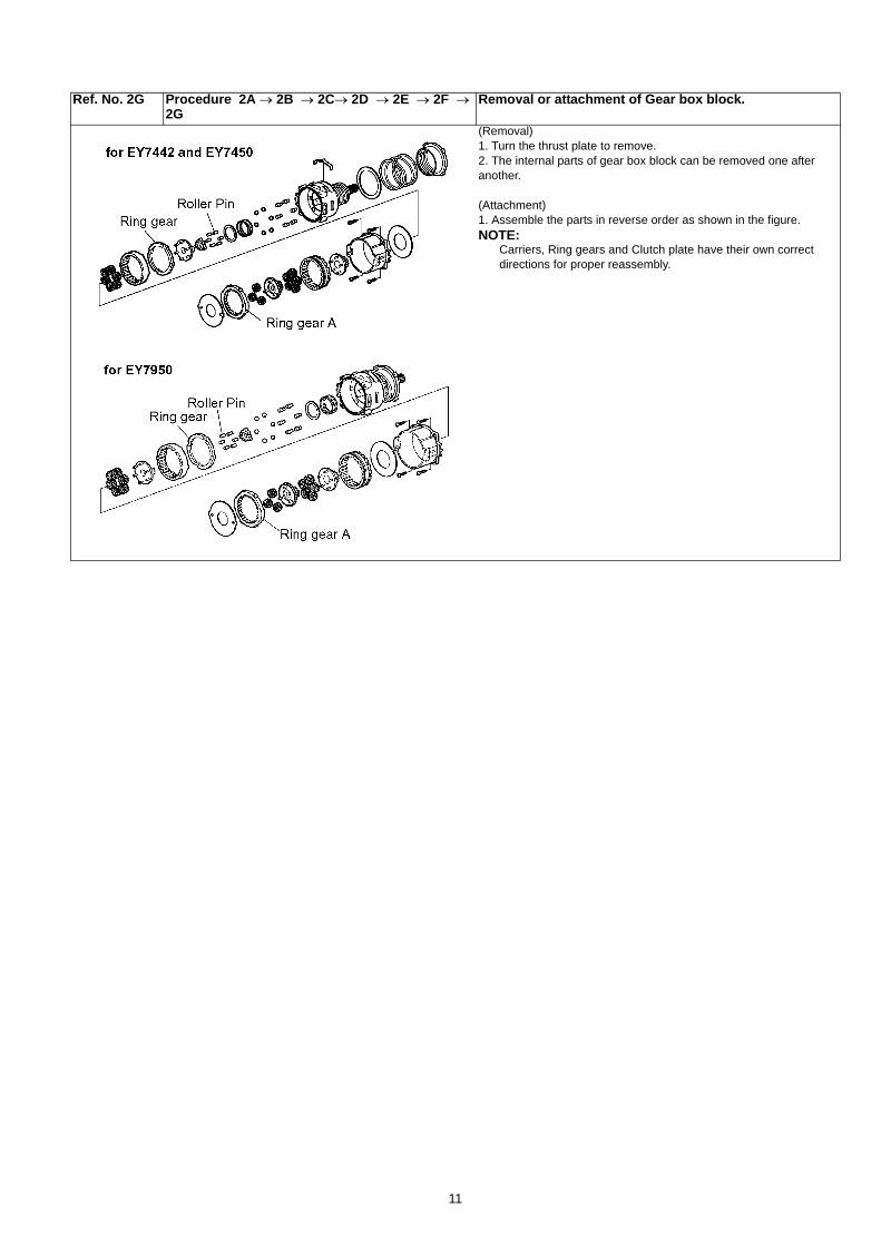
Ref. No. 2G Procedure 2A → 2B → 2C→ 2D → 2E → 2F → 2G
Removal or attachment of Gear box block.
(Removal)1. Turn the thrust plate to remove.2. The internal parts of gear box block can be removed one after another.
(Attachment)1. Assemble the parts in reverse order as shown in the figure.NOTE:
Carriers, Ring gears and Clutch plate have their own correct directions for proper reassembly.
12
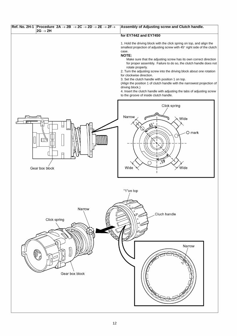
Ref. No. 2H-1 Procedure 2A → 2B → 2C → 2D → 2E → 2F→ 2G → 2H
Assembly of Adjusting screw and Clutch handle.
for EY7442 and EY7450
1. Hold the driving block with the click spring on top, and align the smallest projection of adjusting screw with 45° right side of the clutch case.NOTE:
Make sure that the adjusting screw has its own correct direction for proper assembly. Failure to do so, the clutch handle does not rotate properly.
2. Turn the adjusting screw into the driving block about one rotation for clockwise direction.3. Set the clutch handle with position 1 on top.(Align the position 1 of clutch handle with the narrowest projection of driving block.)4. Insert the clutch handle with adjusting the tabs of adjusting screw to the groove of inside clutch handle.
13
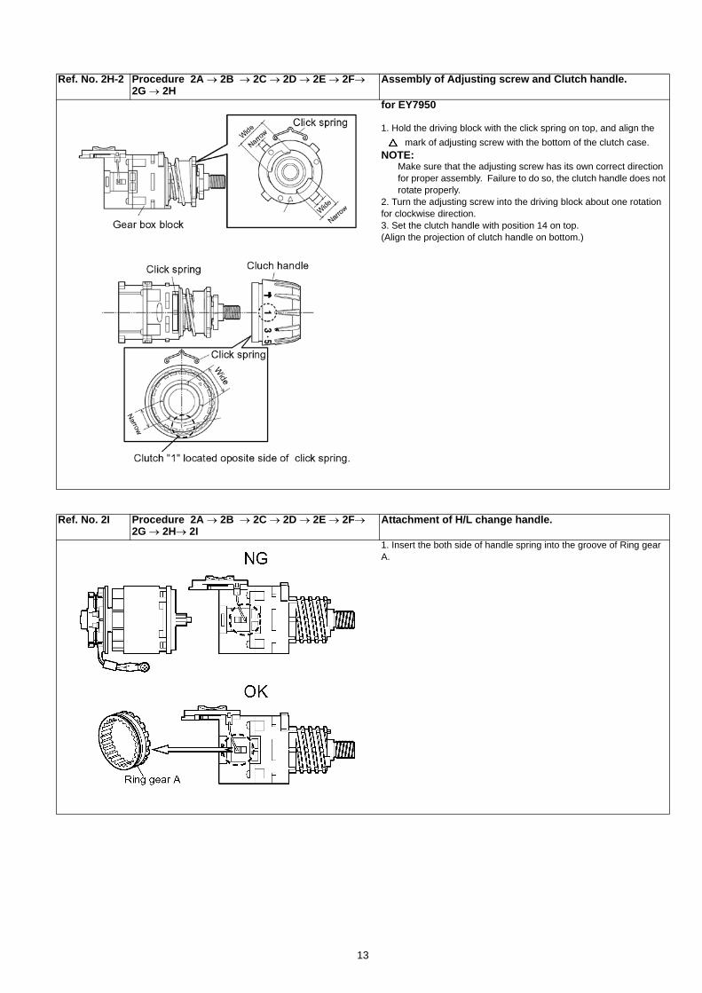
Ref. No. 2H-2 Procedure 2A → 2B → 2C → 2D → 2E → 2F→ 2G → 2H
Assembly of Adjusting screw and Clutch handle.
for EY7950
1. Hold the driving block with the click spring on top, and align the mark of adjusting screw with the bottom of the clutch case.
NOTE:Make sure that the adjusting screw has its own correct direction for proper assembly. Failure to do so, the clutch handle does not rotate properly.
2. Turn the adjusting screw into the driving block about one rotation for clockwise direction.3. Set the clutch handle with position 14 on top.(Align the projection of clutch handle on bottom.)
Ref. No. 2I Procedure 2A → 2B → 2C → 2D → 2E → 2F→ 2G → 2H→ 2I
Attachment of H/L change handle.
1. Insert the both side of handle spring into the groove of Ring gear A.
14
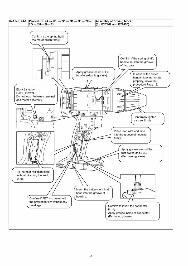
Ref. No. 2J-1 Procedure 2A → 2B → 2C → 2D → 2E → 2F→ 2G → 2H→ 2I→ 2J
Assembly of Driving block. (for EY7442 and EY7450)
15
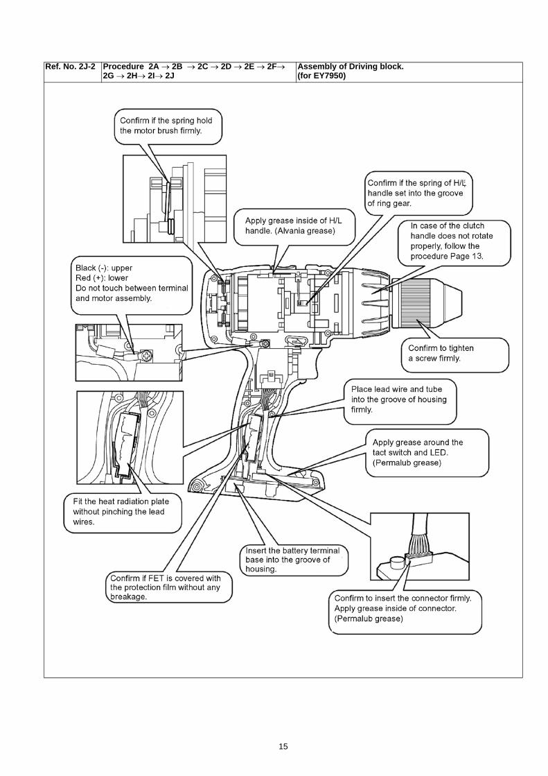
Ref. No. 2J-2 Procedure 2A → 2B → 2C → 2D → 2E → 2F→ 2G → 2H→ 2I→ 2J
Assembly of Driving block. (for EY7950)
16
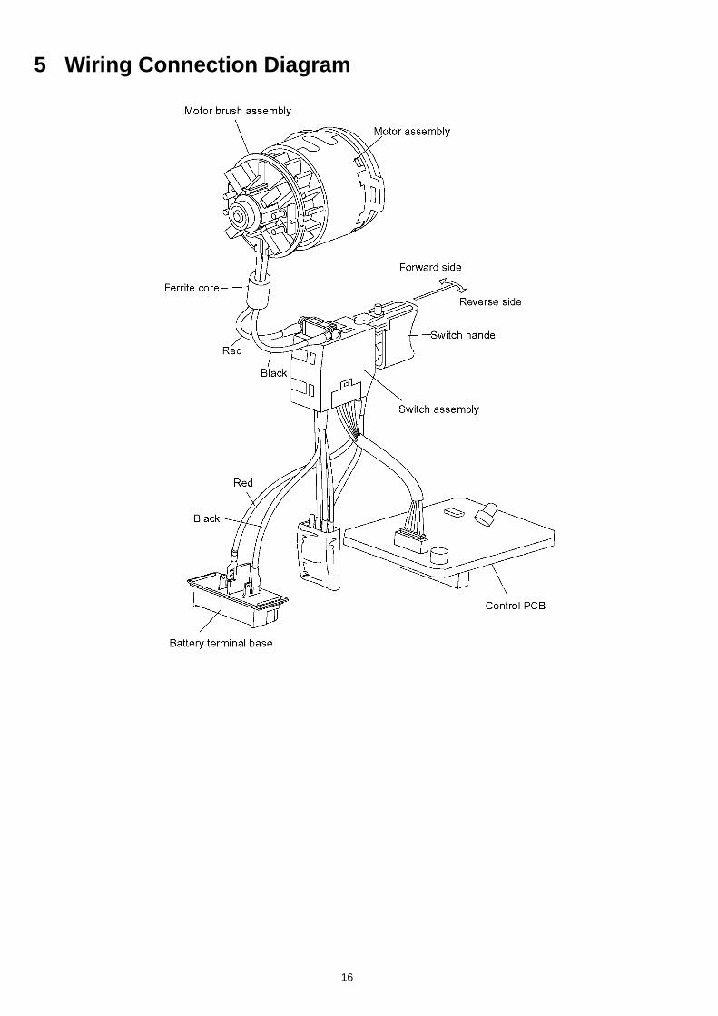
5 Wiring Connection Diagram
17
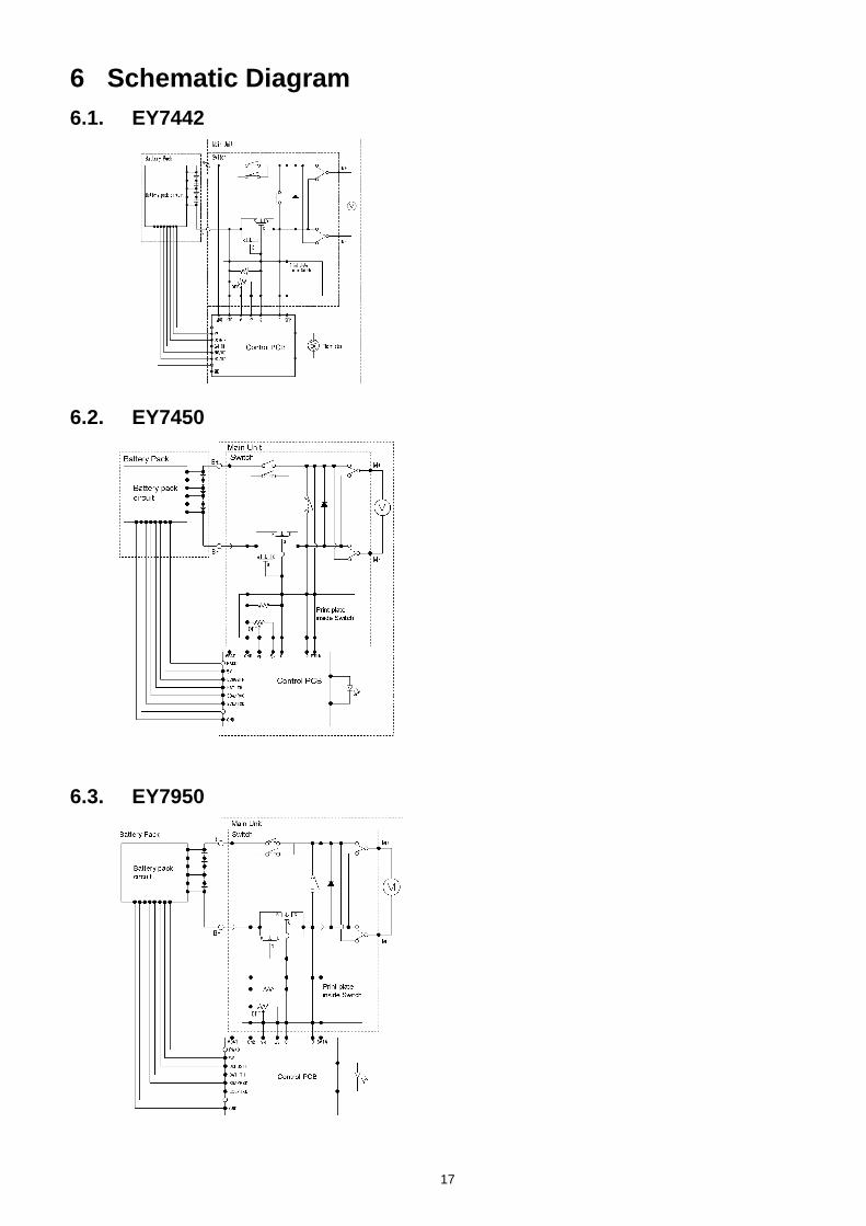
6 Schematic Diagram6.1. EY7442
6.2. EY7450
6.3. EY7950
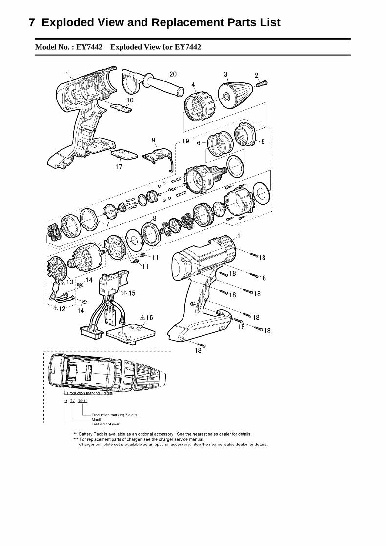
Model No. : EY7442 Exploded View for EY7442
7 Exploded View and Replacement Parts List
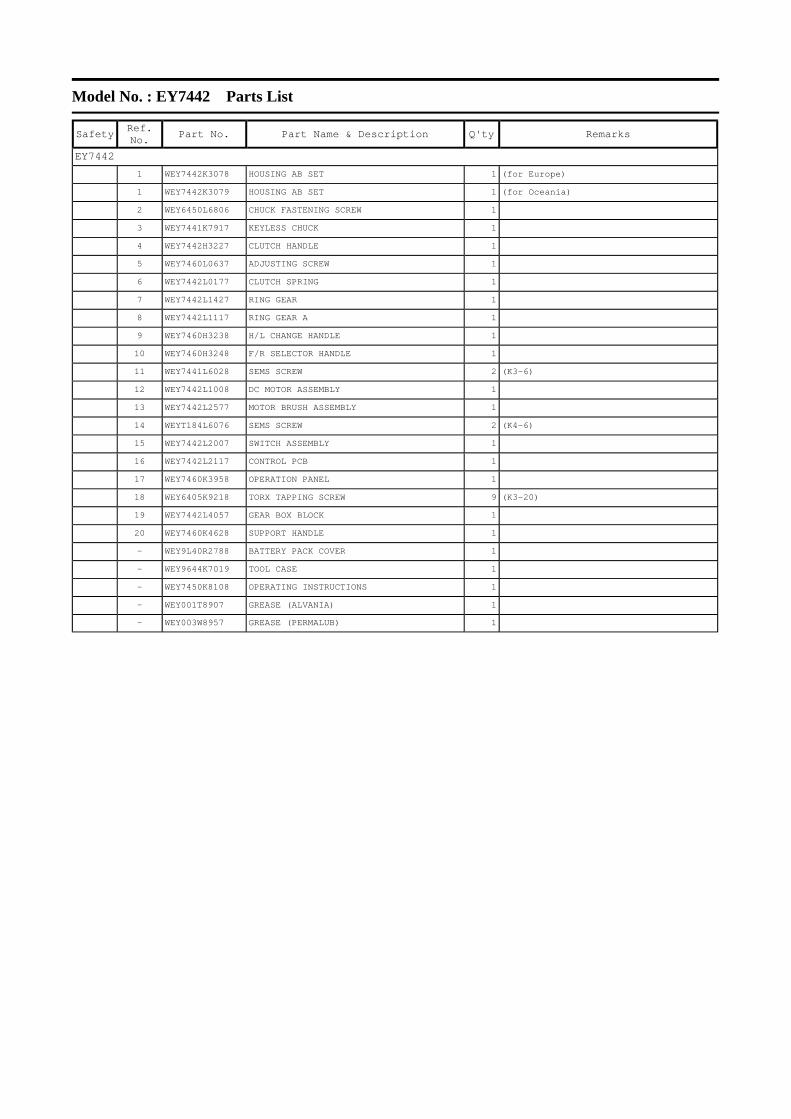
Model No. : EY7442 Parts List
Safety
Ref. No. Part No. Part Name & Description Q'ty Remarks
EY7442
1 WEY7442K3078 HOUSING AB SET 1 (for Europe)
1 WEY7442K3079 HOUSING AB SET 1 (for Oceania)
2 WEY6450L6806 CHUCK FASTENING SCREW 1
3 WEY7441K7917 KEYLESS CHUCK 1
4 WEY7442H3227 CLUTCH HANDLE 1
5 WEY7460L0637 ADJUSTING SCREW 1
6 WEY7442L0177 CLUTCH SPRING 1
7 WEY7442L1427 RING GEAR 1
8 WEY7442L1117 RING GEAR A 1
9 WEY7460H3238 H/L CHANGE HANDLE 1
10 WEY7460H3248 F/R SELECTOR HANDLE 1
11 WEY7441L6028 SEMS SCREW 2 (K3-6)
12 WEY7442L1008 DC MOTOR ASSEMBLY 1
13 WEY7442L2577 MOTOR BRUSH ASSEMBLY 1
14 WEYT184L6076 SEMS SCREW 2 (K4-6)
15 WEY7442L2007 SWITCH ASSEMBLY 1
16 WEY7442L2117 CONTROL PCB 1
17 WEY7460K3958 OPERATION PANEL 1
18 WEY6405K9218 TORX TAPPING SCREW 9 (K3-20)
19 WEY7442L4057 GEAR BOX BLOCK 1
20 WEY7460K4628 SUPPORT HANDLE 1
- WEY9L40R2788 BATTERY PACK COVER 1
- WEY9644K7019 TOOL CASE 1
- WEY7450K8108 OPERATING INSTRUCTIONS 1
- WEY001T8907 GREASE (ALVANIA) 1
- WEY003W8957 GREASE (PERMALUB) 1
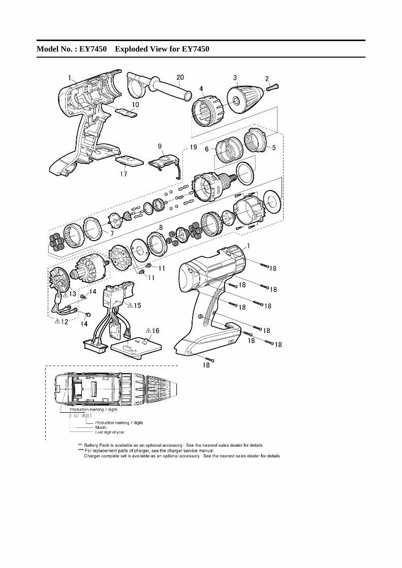
Model No. : EY7450 Exploded View for EY7450

Model No. : EY7450 Parts List
Safety
Ref. No. Part No. Part Name & Description Q'ty Remarks
EY7450
1 WEY7450K3079 HOUSING AB SET 1 (for Europe)
1 WEY7450K3070 HOUSING AB SET 1 (for Oceania)
2 WEY6450L6806 CHUCK FASTENING SCREW 1
3 WEY7441K7917 KEYLESS CHUCK 1
4 WEY7442H3227 CLUTCH HANDLE 1
5 WEY7460L0637 ADJUSTING SCREW 1
6 WEY7442L0177 CLUTCH SPRING 1
7 WEY7442L1427 RING GEAR 1
8 WEY7442L1117 RING GEAR A 1
9 WEY7460H3238 H/L CHANGE HANDLE 1
10 WEY7460H3248 F/R SELECTOR HANDLE 1
11 WEY7441L6028 SEMS SCREW 2 (K3-6)
12 WEY7450L1008 DC MOTOR ASSEMBLY 1
13 WEY7442L2577 MOTOR BRUSH ASSEMBLY 1
14 WEYT184L6076 SEMS SCREW 2 (K4-6)
15 WEY7442L2007 SWITCH ASSEMBLY 1
16 WEY7450L2117 CONTROL PCB 1
17 WEY7460K3958 OPERATION PANEL 1
18 WEY6405K9218 TORX TAPPING SCREW 9 (K3-20)
19 WEY7442L4057 GEAR BOX BLOCK 1
20 WEY7460K4628 SUPPORT HANDLE 1
- WEY9L40R2788 BATTERY PACK COVER 1
- WEY9644K7019 TOOL CASE 1
- WEY7450K8109 OPERATING INSTRUCTIONS 1
- WEY001T8907 GREASE (ALVANIA)
- WEY003W8957 GREASE (PERMALUB)
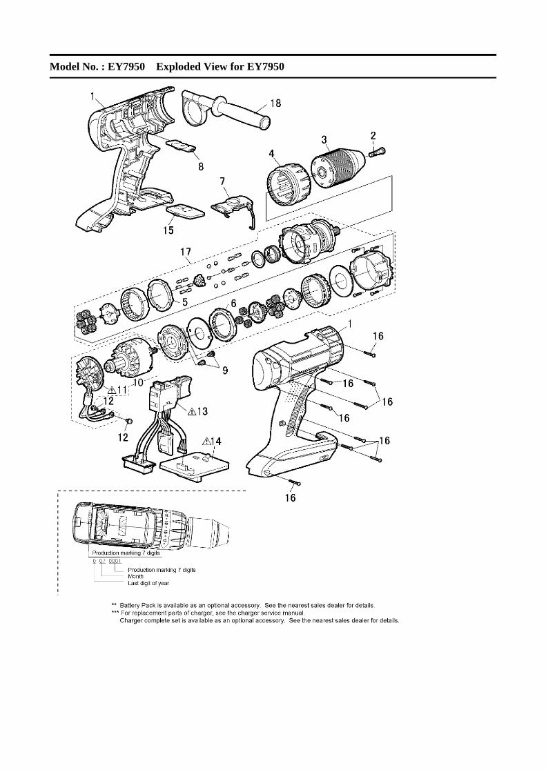
Model No. : EY7950 Exploded View for EY7950
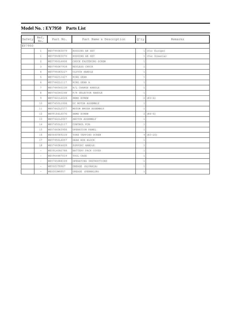
Model No. : EY7950 Parts List
Safety
Ref. No. Part No. Part Name & Description Q'ty Remarks
EY7950
1 WEY7950K3079 HOUSING AB SET 1 (for Europe)
1 WEY7950K3070 HOUSING AB SET 1 (for Oceania)
2 WEY7950L6808 CHUCK FASTENING SCREW 1
3 WEY7950K7918 KEYLESS CHUCK 1
4 WEY7950K3227 CLUTCH HANDLE 1
5 WEY7442L1427 RING GEAR 1
6 WEY7442L1117 RING GEAR A 1
7 WEY7460H3238 H/L CHANGE HANDLE 1
8 WEY7460H3248 F/R SELECTOR HANDLE 1
9 WEY7441L6028 SEMS SCREW 2 (K3-6)
10 WEY7450L1008 DC MOTOR ASSEMBLY 1
11 WEY7442L2577 MOTOR BRUSH ASSEMBLY 1
12 WEYT184L6076 SEMS SCREW 2 (K4-6)
13 WEY7442L2007 SWITCH ASSEMBLY 1
14 WEY7450L2117 CONTROL PCB 1
15 WEY7460K3958 OPERATION PANEL 1
16 WEY6405K9218 TORX TAPPING SCREW 9 (K3-20)
17 WEY7950L4057 GEAR BOX BLOCK 1
18 WEY7460K4628 SUPPORT HANDLE 1
- WEY9L40R2788 BATTERY PACK COVER 1
- WEY9644K7019 TOOL CASE 1
- WEY7450K8109 OPERATING INSTRUCTIONS 1
- WEY001T8907 GREASE (ALVANIA) 1
- WEY003W8957 GREASE (PERMALUB) 1
Recommended