Critical face pressure and backfill pressure in shield TBM tunneling on soft ground
Kiseok Kim1), Juyoung Oh2), Hyobum Lee3) and Hangseok Choi4)
1), 3), 4) Department of civil engineering, Korea University, Seoul, Korea
2) Samsung C&T Corporation, Seoul, Korea 1) [email protected] 2) [email protected]
3) [email protected] 4) [email protected]
ABSTRACT
The most important issue during shield TBM tunneling in soft ground formations is to
appropriately control ground surface settlement. Among various operational conditions
in shield TBM tunneling, the face pressure and backfill pressure should be the most
important and immediate factor to restrain surface settlement during excavation. In this
paper, a 3-D hydro-mechanical coupled FE model is developed to numerically simulate
the whole process of shield TBM tunneling, which is verified by comparing with real
field measurements of ground surface settlement. The effect of permeability and
stiffness of ground formations on tunneling-induced surface settlement was discussed
in the parametric study. An increase in the face pressure and backfill pressure does not
always lead to a decrease in surface settlement, but there are the critical face pressure
and backfill pressure. In addition, considering the relatively low permeability of ground
formations, the surface settlement consists of two parts, i.e., immediate settlement and
consolidation settlement, which shows a distinct settlement behavior to each other.
1. INTRODUCTION
The construction of tunnels has considerably increased during the last few decades in urban areas because of the growing demand for development of underground space to accommodate underground facilities such as subways, underground roads, water and sewage tunnels and gas tunnels. In constructing a new tunnel, the proximity of these underground facilities from one to another becomes unavoidable, and underground space is getting more complicated. In general, conventional tunneling methods have been employed in urban areas. But, for soft ground formations under the ground water level, the conventional methods

cannot appropriately cope with the ground subsidence. As the excavation technology has improved, the subsidence can now be controlled by shield tunneling, using shield Tunnel Boring Machines (TBMs) that adopts a rigid steel protector to support the ground and apply pressure on the tunnel face and tail void, and then fulfills excavation safely.
Even with the current rise of computer technology and high-performance numerical methods, a clear standard of numerical analysis for a shield tunneling process does not exist because the numerical analysis for simulating shield TBM tunneling is extremely complicated and requires a number of inevitable assumptions. In this paper, a 3-D hydro-mechanical coupled FE model is developed to numerically simulate the whole process of shield TBM tunneling construction in less permeable ground, in which consolidation may occur. The FE analysis simulating the excavation of a slurry shield TBM was facilitated along with the commercial program ABAQUS (v. 6.14), which was verified by comparing with the field data obtained from the Hong-Kong site. In the parametric study, the effect of permeability and stiffness of ground formations on tunneling-induced surface settlement during shield TBM tunneling was discussed. The main purpose of this paper is to study the influence of operational conditions on the ground surface settlement. Among various operational conditions in shield TBM tunneling, the face pressure and backfill pressure are considered to be the most important and immediate factor to restrain surface settlement during excavation. In dealing with a relatively less permeable ground formations, the surface settlement consists of two parts, i.e., immediate settlement and consolidation settlement, which shows a distinct settlement behavior to each other. From a construction management perspective during shield TBM tunneling, the immediate settlement attracts a shot-term effect of tunnel construction on the ground surface deformation. On the other hand, the consolidation settlement is related to a long-term management issue after completion of tunnel construction. The influence of the face pressure and backfill pressure on the surface settlement was discussed by introducing a new concept of critical pressure. 2. DEVELOPMENT OF THE FE MODEL FOR SHIELD TBM 2.1 Materials
The FE model for a slurry shield TBM tunneling consists of 4 parts: ground formation, grout, shield and lining (Fig. 1). The solid element modeled for the ground formation is composed of 20-nodes. To simulate the two-phase formulation (ground (solid) and water), 8 nodes are added to represent pore water pressure, and the values between the nodes are approximated by linear interpolation. The grout is modeled with 20-node solid elements considering a quadratic displacement approximation. The grout is regarded as a saturated porous material. The reduction in permeability of hydrating cement at the early stage is considered. The hydration process is assumed to be time-dependent and the exponential function proposed by Kasper (2004) was applied to describe the decrease in permeability of grout (Fig. 2). The shield is designed in a cylindrical shape with conicity modeled with shell elements. By assigning much higher stiffness in relation to the ground, the shield machine is regarded as a rigid body. The segment lining is simplified as a continuous, elastic tube using square volume elements
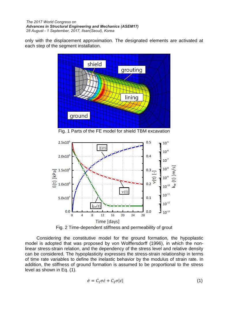
only with the displacement approximation. The designated elements are activated at each step of the segment installation.
Fig. 1 Parts of the FE model for shield TBM excavation
Fig. 2 Time-dependent stiffness and permeability of grout
Considering the constitutive model for the ground formation, the hypoplastic
model is adopted that was proposed by von Wolffersdorff (1996), in which the non-linear stress-strain relation, and the dependency of the stress level and relative density can be considered. The hypoplasticity expresses the stress-strain relationship in terms of time rate variables to define the inelastic behavior by the modulus of strain rate. In addition, the stiffness of ground formation is assumed to be proportional to the stress level as shown in Eq. (1).
�̇� = 𝐶1𝜎𝜀̇ + 𝐶2𝜎|𝜀̇| (1)

Because the von Wolffersdorff model is able to consider a change in void ratio
during loading/unloading, a unique relationship can be adopted for both loading and unloading without any intentional classification between elastic and plastic deformations.
In a tensor notation, the stress rate tensor (�̇�𝑠) is determined in function of the strain rate (D), skeleton (effective) stress (𝑇𝑠), and void ratio (e) (refer to Eq. (2)).
�̇�𝑠 = ℎ(𝑇𝑠, 𝐷, 𝑒) (2) 2.2 Numerical modeling
In order to implement the boundary conditions in the numerical model for slurry shield TBM tunneling, only one half of the tunnel is considered, and the horizontal displacements are restricted on the symmetry plane. The vertical displacements at the front, rear, and side planes are set to be zero. The ground water level is assumed to be on the ground surface, and the boundary condition of pore water pressure is formulated as hydrostatic on the lateral level. These boundary conditions remain undisturbed during the numerical simulation. The outer boundaries including the symmetry plane are assumed to be impermeable.
In the course of excavation of a shield TBM, the stability of face is extremely important to ensure stable ground formations. The shield machine excavates the ground in the face, which is pressurized (i.e., face pressure) by slurry (in the slurry shield TBM) or excavated earthen material (in the EPB shield TBM). Especially in the slurry shield TBM, it is assumed that the filter cake is formed completely on the surface of tunnel face, and the slurry-induced linear pressure distribution over the height of the face is exerted. Assuming that ground deformation at the tunnel face is small, the face pressure at the crown is adjusted according to the total primary stress. The backfill pressure applied into the annular gap by grouting causes an additional load transferred to the ground and the segment lining. The magnitude and implementation of backfill pressure in the model is illustrated in Fig. 3. The unit weight of the pressurized mortar,
is assumed to be 21 kN/𝑚3 in the current numerical model. The driving of a shield TBM is simulated by adopting the activation and
deactivation application. After a certain excavation stage, the existing elements of the shield machine and the existing contact should be deactivated, and at the same time, the new elements of the shield machine and the corresponding contacts, which are 1.5 m (advance length) ahead, are activated. After the shield advances along with lining installation, the backfill pressure is applied on the excavation surface and the segment lining. Subsequently, the first elements of grout are activated at the same time, and these elements are loaded and the existing pressure is released. After this step, the new tunnel lining and contacts are activated. These simulation steps are repeated until the shield machine completes excavation. After the excavation, an additional calculation step takes place to simulate the consolidation process.
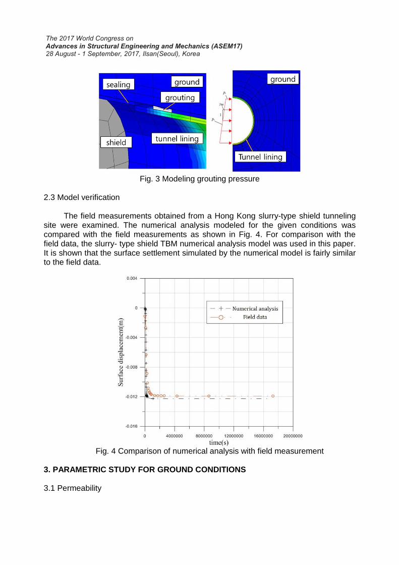
Fig. 3 Modeling grouting pressure
2.3 Model verification
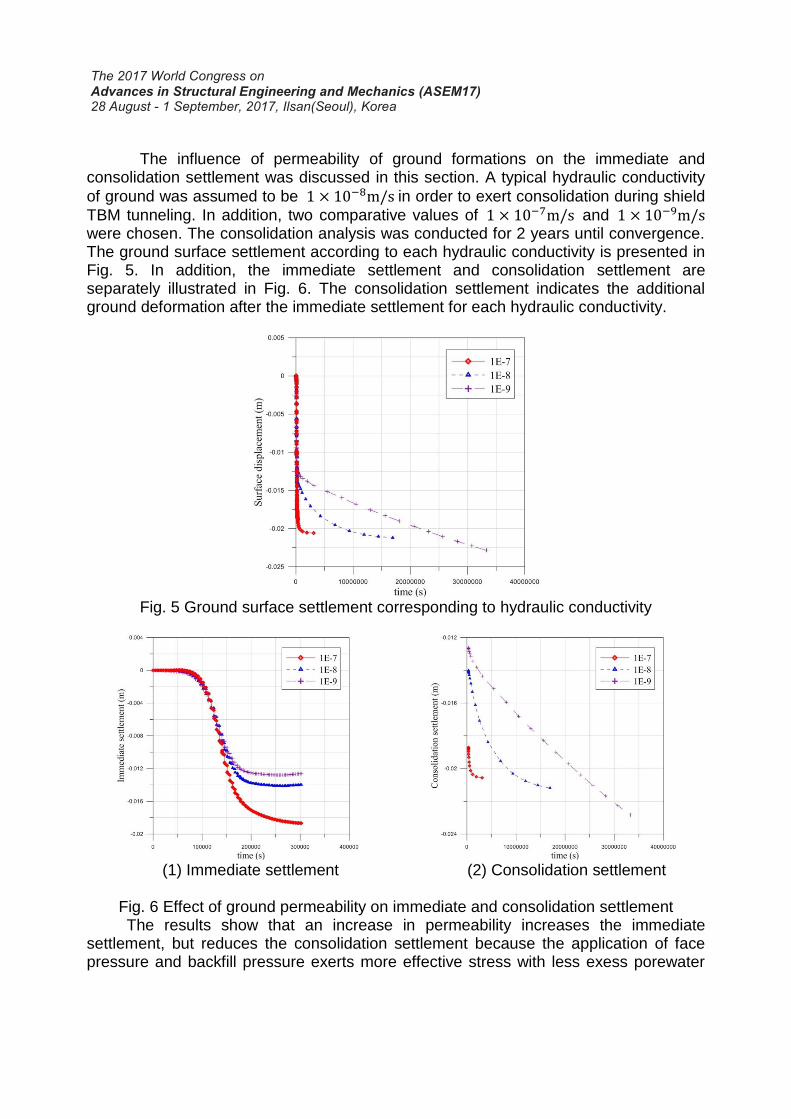
The field measurements obtained from a Hong Kong slurry-type shield tunneling site were examined. The numerical analysis modeled for the given conditions was compared with the field measurements as shown in Fig. 4. For comparison with the field data, the slurry- type shield TBM numerical analysis model was used in this paper. It is shown that the surface settlement simulated by the numerical model is fairly similar to the field data.
Fig. 4 Comparison of numerical analysis with field measurement
3. PARAMETRIC STUDY FOR GROUND CONDITIONS 3.1 Permeability
The influence of permeability of ground formations on the immediate and consolidation settlement was discussed in this section. A typical hydraulic conductivity
of ground was assumed to be 1 × 10⁻⁸m/s in order to exert consolidation during shield
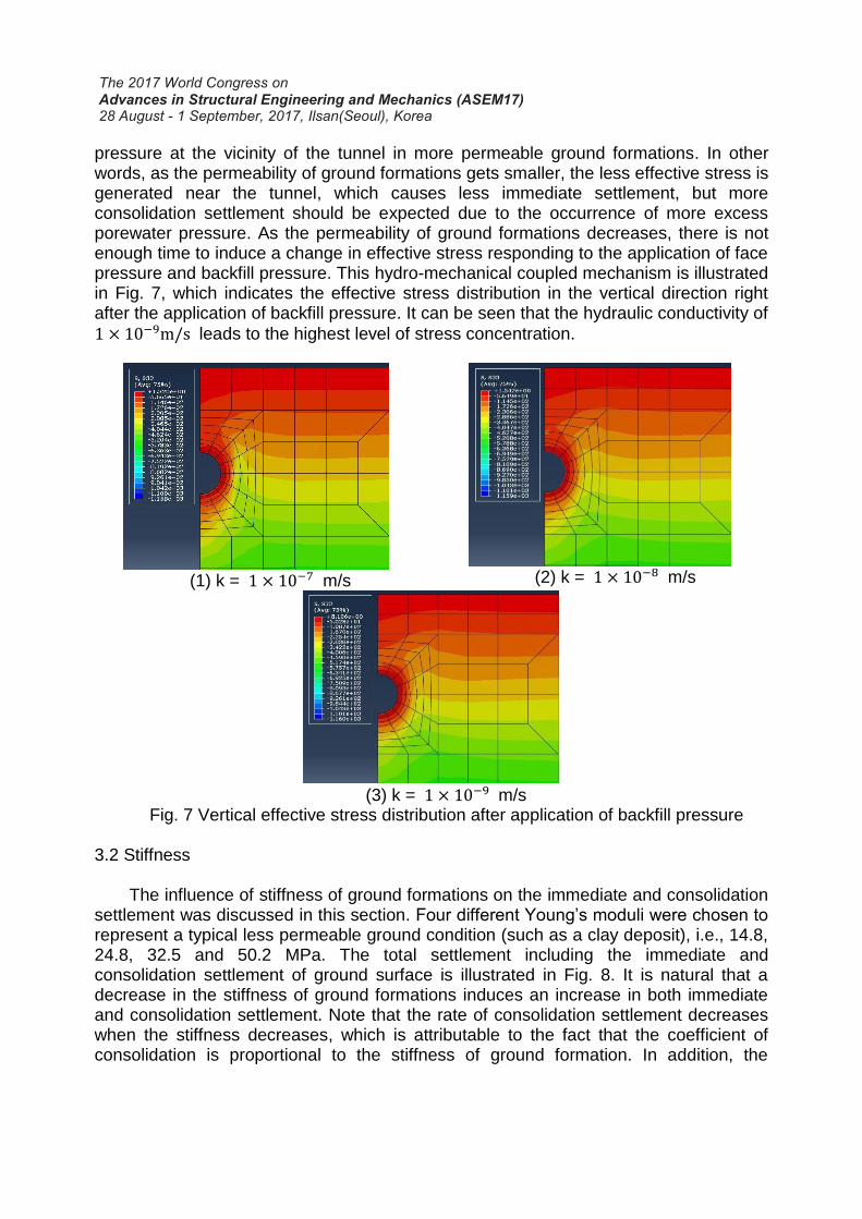
TBM tunneling. In addition, two comparative values of 1 × 10⁻⁷m/s and 1 × 10⁻⁹m/s were chosen. The consolidation analysis was conducted for 2 years until convergence. The ground surface settlement according to each hydraulic conductivity is presented in Fig. 5. In addition, the immediate settlement and consolidation settlement are separately illustrated in Fig. 6. The consolidation settlement indicates the additional ground deformation after the immediate settlement for each hydraulic conductivity.
Fig. 5 Ground surface settlement corresponding to hydraulic conductivity
(1) Immediate settlement
(2) Consolidation settlement
Fig. 6 Effect of ground permeability on immediate and consolidation settlement
The results show that an increase in permeability increases the immediate settlement, but reduces the consolidation settlement because the application of face pressure and backfill pressure exerts more effective stress with less exess porewater
pressure at the vicinity of the tunnel in more permeable ground formations. In other words, as the permeability of ground formations gets smaller, the less effective stress is generated near the tunnel, which causes less immediate settlement, but more consolidation settlement should be expected due to the occurrence of more excess porewater pressure. As the permeability of ground formations decreases, there is not enough time to induce a change in effective stress responding to the application of face pressure and backfill pressure. This hydro-mechanical coupled mechanism is illustrated in Fig. 7, which indicates the effective stress distribution in the vertical direction right after the application of backfill pressure. It can be seen that the hydraulic conductivity of
1 × 10⁻⁹m/s leads to the highest level of stress concentration.
(1) k = 1 × 10⁻⁷ m/s
(2) k = 1 × 10⁻⁸ m/s
(3) k = 1 × 10⁻⁹ m/s
Fig. 7 Vertical effective stress distribution after application of backfill pressure 3.2 Stiffness The influence of stiffness of ground formations on the immediate and consolidation settlement was discussed in this section. Four different Young’s moduli were chosen to represent a typical less permeable ground condition (such as a clay deposit), i.e., 14.8, 24.8, 32.5 and 50.2 MPa. The total settlement including the immediate and consolidation settlement of ground surface is illustrated in Fig. 8. It is natural that a decrease in the stiffness of ground formations induces an increase in both immediate and consolidation settlement. Note that the rate of consolidation settlement decreases when the stiffness decreases, which is attributable to the fact that the coefficient of consolidation is proportional to the stiffness of ground formation. In addition, the
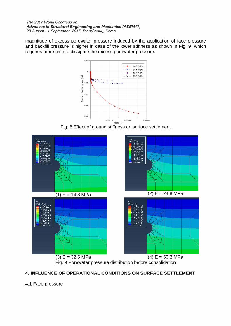
magnitude of excess porewater pressure induced by the application of face pressure and backfill pressure is higher in case of the lower stiffness as shown in Fig. 9, which requires more time to dissipate the excess porewater pressure.
Fig. 8 Effect of ground stiffness on surface settlement
(1) E = 14.8 MPa
(2) E = 24.8 MPa
(3) E = 32.5 MPa
(4) E = 50.2 MPa
Fig. 9 Porewater pressure distribution before consolidation 4. INFLUENCE OF OPERATIONAL CONDITIONS ON SURFACE SETTLEMENT 4.1 Face pressure
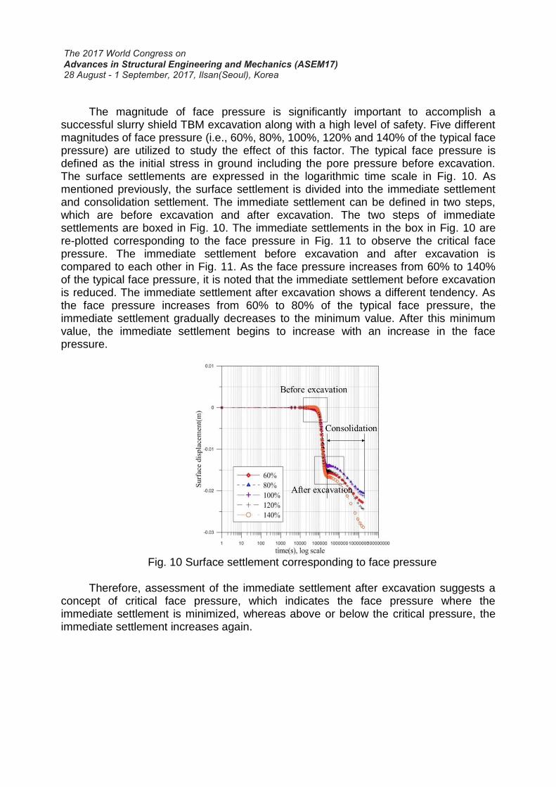
The magnitude of face pressure is significantly important to accomplish a
successful slurry shield TBM excavation along with a high level of safety. Five different magnitudes of face pressure (i.e., 60%, 80%, 100%, 120% and 140% of the typical face pressure) are utilized to study the effect of this factor. The typical face pressure is defined as the initial stress in ground including the pore pressure before excavation. The surface settlements are expressed in the logarithmic time scale in Fig. 10. As mentioned previously, the surface settlement is divided into the immediate settlement and consolidation settlement. The immediate settlement can be defined in two steps, which are before excavation and after excavation. The two steps of immediate settlements are boxed in Fig. 10. The immediate settlements in the box in Fig. 10 are re-plotted corresponding to the face pressure in Fig. 11 to observe the critical face pressure. The immediate settlement before excavation and after excavation is compared to each other in Fig. 11. As the face pressure increases from 60% to 140% of the typical face pressure, it is noted that the immediate settlement before excavation is reduced. The immediate settlement after excavation shows a different tendency. As the face pressure increases from 60% to 80% of the typical face pressure, the immediate settlement gradually decreases to the minimum value. After this minimum value, the immediate settlement begins to increase with an increase in the face pressure.
Fig. 10 Surface settlement corresponding to face pressure
Therefore, assessment of the immediate settlement after excavation suggests a
concept of critical face pressure, which indicates the face pressure where the immediate settlement is minimized, whereas above or below the critical pressure, the immediate settlement increases again.
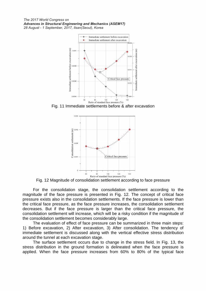
Fig. 11 Immediate settlements before & after excavation
Fig. 12 Magnitude of consolidation settlement according to face pressure
For the consolidation stage, the consolidation settlement according to the
magnitude of the face pressure is presented in Fig. 12. The concept of critical face pressure exists also in the consolidation settlements. If the face pressure is lower than the critical face pressure, as the face pressure increases, the consolidation settlement decreases. But if the face pressure is larger than the critical face pressure, the consolidation settlement will increase, which will be a risky condition if the magnitude of the consolidation settlement becomes considerably large.
The evaluation of effect of face pressure can be summarized in three main steps: 1) Before excavation, 2) After excavation, 3) After consolidation. The tendency of immediate settlement is discussed along with the vertical effective stress distribution around the tunnel at each excavation stage.
The surface settlement occurs due to change in the stress field. In Fig. 13, the stress distribution in the ground formation is delineated when the face pressure is applied. When the face pressure increases from 60% to 80% of the typical face
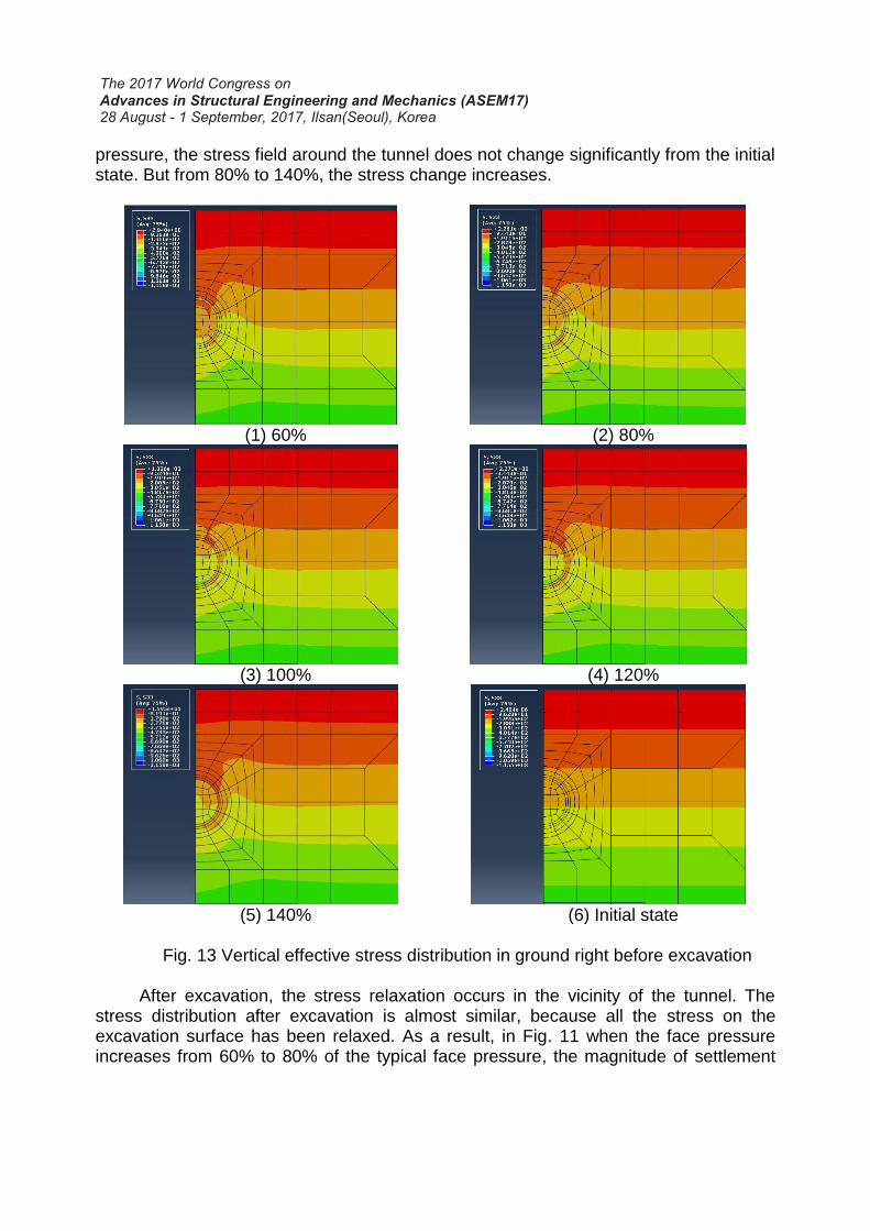
pressure, the stress field around the tunnel does not change significantly from the initial state. But from 80% to 140%, the stress change increases.
(1) 60%
(2) 80%
(3) 100%
(4) 120%
(5) 140%
(6) Initial state
Fig. 13 Vertical effective stress distribution in ground right before excavation
After excavation, the stress relaxation occurs in the vicinity of the tunnel. The stress distribution after excavation is almost similar, because all the stress on the excavation surface has been relaxed. As a result, in Fig. 11 when the face pressure increases from 60% to 80% of the typical face pressure, the magnitude of settlement
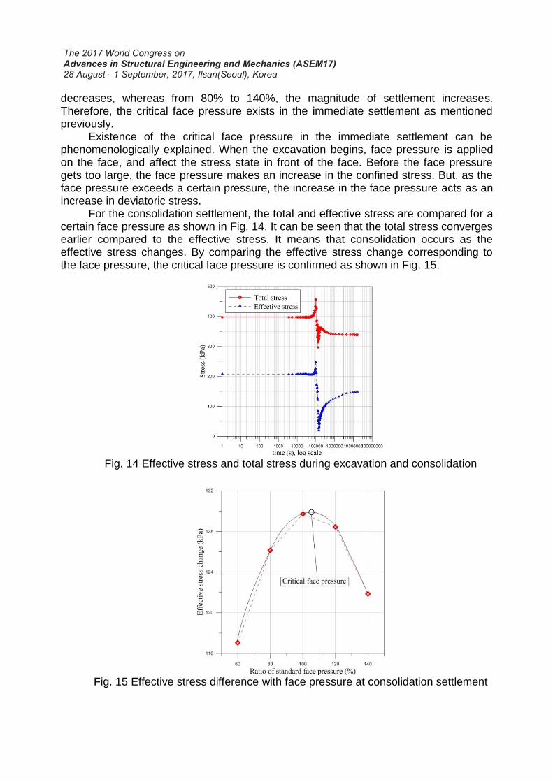
decreases, whereas from 80% to 140%, the magnitude of settlement increases. Therefore, the critical face pressure exists in the immediate settlement as mentioned previously.
Existence of the critical face pressure in the immediate settlement can be phenomenologically explained. When the excavation begins, face pressure is applied on the face, and affect the stress state in front of the face. Before the face pressure gets too large, the face pressure makes an increase in the confined stress. But, as the face pressure exceeds a certain pressure, the increase in the face pressure acts as an increase in deviatoric stress.
For the consolidation settlement, the total and effective stress are compared for a certain face pressure as shown in Fig. 14. It can be seen that the total stress converges earlier compared to the effective stress. It means that consolidation occurs as the effective stress changes. By comparing the effective stress change corresponding to the face pressure, the critical face pressure is confirmed as shown in Fig. 15.
Fig. 14 Effective stress and total stress during excavation and consolidation
Fig. 15 Effective stress difference with face pressure at consolidation settlement
4.2 Backfill pressure
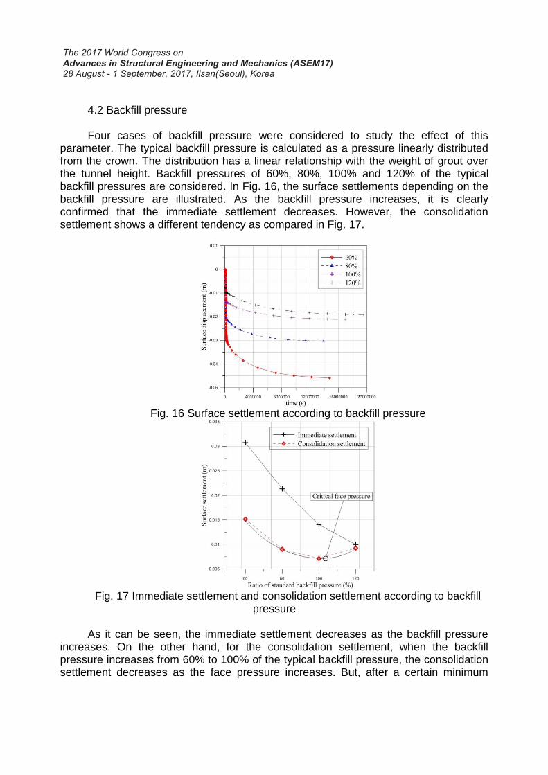
Four cases of backfill pressure were considered to study the effect of this parameter. The typical backfill pressure is calculated as a pressure linearly distributed from the crown. The distribution has a linear relationship with the weight of grout over the tunnel height. Backfill pressures of 60%, 80%, 100% and 120% of the typical backfill pressures are considered. In Fig. 16, the surface settlements depending on the backfill pressure are illustrated. As the backfill pressure increases, it is clearly confirmed that the immediate settlement decreases. However, the consolidation settlement shows a different tendency as compared in Fig. 17.
Fig. 16 Surface settlement according to backfill pressure
Fig. 17 Immediate settlement and consolidation settlement according to backfill
pressure
As it can be seen, the immediate settlement decreases as the backfill pressure increases. On the other hand, for the consolidation settlement, when the backfill pressure increases from 60% to 100% of the typical backfill pressure, the consolidation settlement decreases as the face pressure increases. But, after a certain minimum
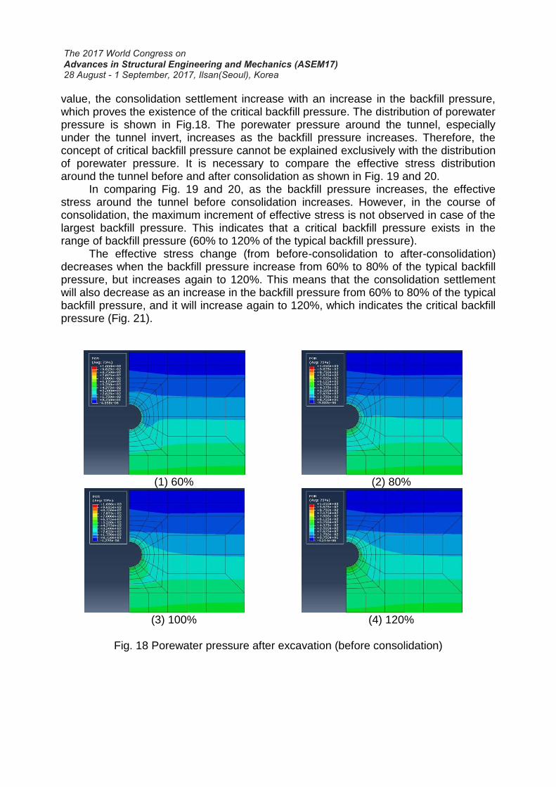
value, the consolidation settlement increase with an increase in the backfill pressure, which proves the existence of the critical backfill pressure. The distribution of porewater pressure is shown in Fig.18. The porewater pressure around the tunnel, especially under the tunnel invert, increases as the backfill pressure increases. Therefore, the concept of critical backfill pressure cannot be explained exclusively with the distribution of porewater pressure. It is necessary to compare the effective stress distribution around the tunnel before and after consolidation as shown in Fig. 19 and 20.
In comparing Fig. 19 and 20, as the backfill pressure increases, the effective stress around the tunnel before consolidation increases. However, in the course of consolidation, the maximum increment of effective stress is not observed in case of the largest backfill pressure. This indicates that a critical backfill pressure exists in the range of backfill pressure (60% to 120% of the typical backfill pressure).
The effective stress change (from before-consolidation to after-consolidation) decreases when the backfill pressure increase from 60% to 80% of the typical backfill pressure, but increases again to 120%. This means that the consolidation settlement will also decrease as an increase in the backfill pressure from 60% to 80% of the typical backfill pressure, and it will increase again to 120%, which indicates the critical backfill pressure (Fig. 21).
(1) 60%
(2) 80%
(3) 100%
(4) 120%
Fig. 18 Porewater pressure after excavation (before consolidation)
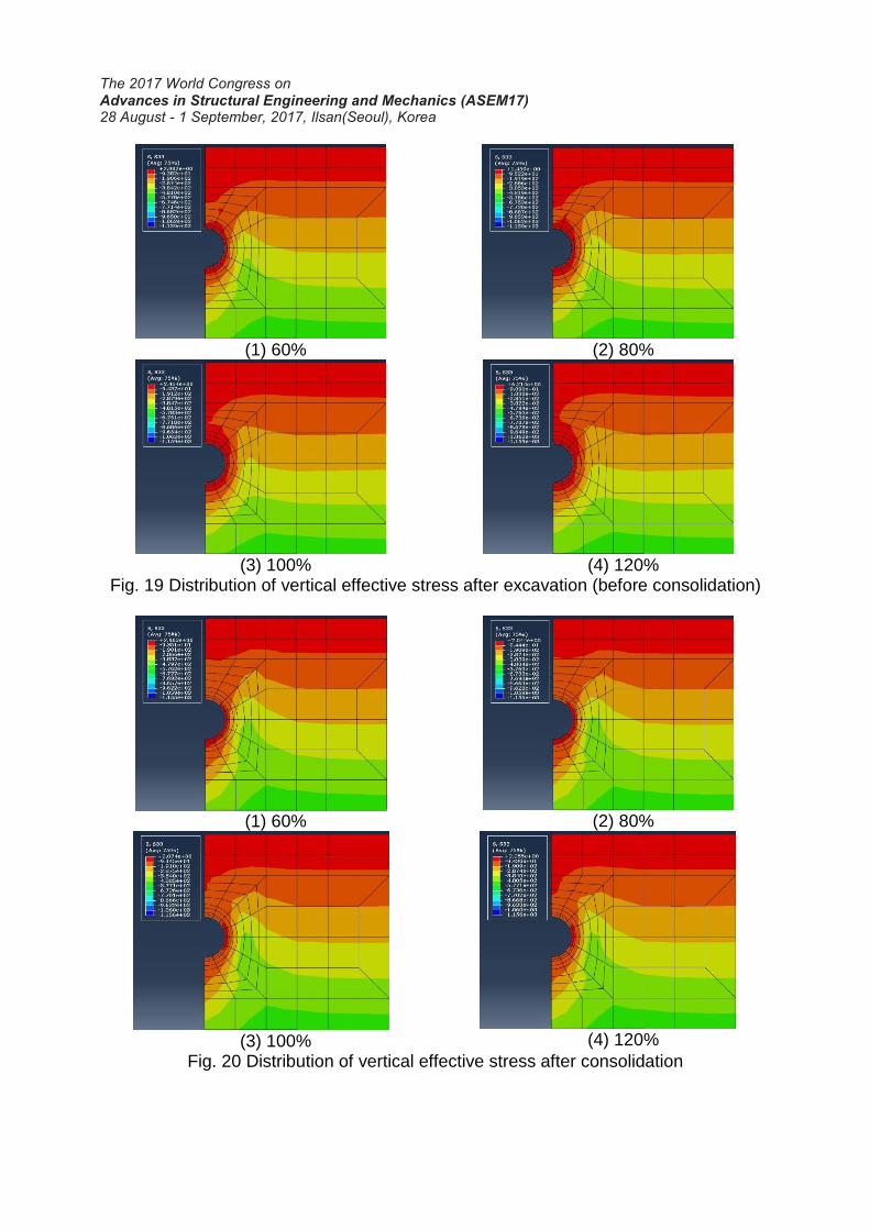
(1) 60%
(2) 80%
(3) 100%
(4) 120%
Fig. 19 Distribution of vertical effective stress after excavation (before consolidation)
(1) 60%
(2) 80%
(3) 100%
(4) 120%
Fig. 20 Distribution of vertical effective stress after consolidation
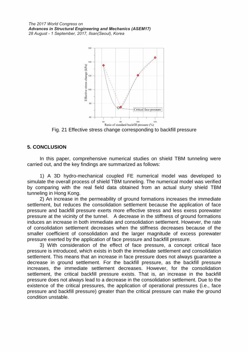
Fig. 21 Effective stress change corresponding to backfill pressure
5. CONCLUSION
In this paper, comprehensive numerical studies on shield TBM tunneling were carried out, and the key findings are summarized as follows:
1) A 3D hydro-mechanical coupled FE numerical model was developed to
simulate the overall process of shield TBM tunneling. The numerical model was verified by comparing with the real field data obtained from an actual slurry shield TBM tunneling in Hong Kong.
2) An increase in the permeability of ground formations increases the immediate settlement, but reduces the consolidation settlement because the application of face pressure and backfill pressure exerts more effective stress and less exess porewater pressure at the vicinity of the tunnel. A decrease in the stiffness of ground formations induces an increase in both immediate and consolidation settlement. However, the rate of consolidation settlement decreases when the stiffness decreases because of the smaller coefficient of consolidation and the larger magnitude of excess porewater pressure exerted by the application of face pressure and backfill pressure.
3) With consideration of the effect of face pressure, a concept critical face pressure is introduced, which exists in both the immediate settlement and consolidation settlement. This means that an increase in face pressure does not always guarantee a decrease in ground settlement. For the backfill pressure, as the backfill pressure increases, the immediate settlement decreases. However, for the consolidation settlement, the critical backfill pressure exists. That is, an increase in the backfill pressure does not always lead to a decrease in the consolidation settlement. Due to the existence of the critical pressures, the application of operational pressures (i.e., face pressure and backfill pressure) greater than the critical pressure can make the ground condition unstable.
ACKNOWLEDGEMENT
This research was supported by the Korea Agency for Infrastructure Technology Advancement under the Ministry of Land, Infrastructure and Transport of the Korean government. (Project Number: 17SCIP-B108153-03)
REFERENCES Abu-Farsakh, M.Y., Voyiadjis, G.Z. (1999): Computational model for the simulation of
the shield tunneling process in cohesive soils. International Journal for Numerical and Analytical Methods in Geomechanics, Vol. 23, S. 23-44.
Anagnostou, G. (1995): The influence of tunnel excavation on the hydraulic head. International Journal for Numerical and Analytical Methods in Geomechanics, Vol. 19, S. 725-746.
Ata, A.A. (1996): Ground settlements induced by slurry shield tunnelling in stratified soils. Proc. North American Tunnelling '96, Vol. 1, S. 43-50.
Au, S.K.A., Soga, K., Jafari, M.R., Bolton, M.D., Komiya, K. (2003): Factors affecting longterm efficiency of compensation grouting in clays. Journal of Geotechnical and Geoenvironmental Engineering, Vol.129 (3), S. 254-262.
Bauer, E. (1996): Calibration of a comprehensive hypoplastic model for granular materials. Soils and Foundations, Vol. 36 (1), S. 13-26.
Herle, I., Gudehus, G. (1999): Determinatioin of parameters of a hypoplastic constitutive model from properties of grain assemblies. Mechanics of Cohesive-Frictional Materials, Vol. 4,S. 461-486.
Herle, I., Kolymbas, D. (2004): Hypoplasticity for soils with low friction angles. Computers and Geotechnics, Vol. 31 (5), S. 365-373.
Terzaghi, K. (1954): Theoretical soil mechanics. John Wiley and Sons, New York. von Wolffersdorff, P.-A. (1996): Hypoplastic relation for granular material with a
predefined limit state surface. Mechanics of Cohesive-Frictional Materials, Vol. 1, S. 251-271.
Ziegler, M., Oh, J.-Y. 2014. Effect of tail void grouting on the surface settlements in soil of low permeability. World Tunnel Congress 2014.
Recommended