International Journal of Engineering Science Invention
ISSN (Online): 2319 – 6734, ISSN (Print): 2319 – 6726
www.ijesi.org ||Volume 4 Issue 3 || March 2015 || PP.37-43
www.ijesi.org 37 | Page
Design and Implementation of Maximum Power Point Tracking
in Photovoltaic Systems
K P J Pradeep1, C Chandra Mouli
2, K Sai Prasad Reddy
3, K Nagabhushan Raju
4
1, 2 Research Scholar,
Dept of Instrumentation, Sri Krishnadevaraya University, Anantapur, Andhra Pradesh,
India 3 Research Scholar,
Dept of Electronics, Sri Krishnadevaraya University, Anantapur, Andhra Pradesh, India
4 Professor, Dept of Instrumentation, Sri Krishnadevaraya University, Anantapur, Andhra Pradesh, India
ABSTRACT: This paper presents an algorithm for maximum power point tracking to optimize photovoltaic
systems. Beta algorithm is a type of MPPT algorithm. It is having fast tracking ability. The algorithm has been
verified on a photovoltaic system modeled in Lab VIEW environment. This algorithm significantly improves the
efficiency during the tracking.
KEYWORDS - Photovoltaic cell, maximum power point tracking (MPPT), Beta method, LabVIEW.
I. INTRODUCTION The world population is increasing day by day and the demand for energy is increasing accordingly.
Oil and coal as the main source of energy nowadays, is expected to end up from the world during the recent
century which explores a serious problem in providing the humanity with an affordable and reliable source of
energy. Renewable energy is derived from natural processes that are replenished constantly. Renewable energies
are inexhaustible and clean. The energy comes from natural resources such as sun, wind, tides, waves, and
geothermal heat. Solar energy is quite simply the energy produced directly by the sun. Solar energy is radiant
light and heat from the sun harnessed using a range of technologies such as photovoltaic, thermal electricity and
etc. A solar cell (also called a photovoltaic cell) is an electrical device that converts the energy of light directly
into electricity by the photovoltaic effect.
A solar panel is a set of solar photovoltaic modules electrically connected and mounted on a
supporting structure. The majority of modules use wafer based crystalline silicon cells or thin-film cells based
on cadmium telluride or silicon. The structural member of a module can either be the top layer or the back layer.
Electrical connections are made in series to achieve a desired output voltage and in parallel to provide a desired
current capability. Several types of solar cells are available. Mono crystalline Solar Cells, Polycrystalline Solar
Cells, Amorphous Silicon (a-Si) Solar Cells, Cadmium Telluride (CdTe) Solar Cells [1].
In general there is only one point on P-V and V-I curve called the maximum power point. At this point
only PV system operates with maximum efficiency and produces maximum output power. A number of MPPT
methods have been developed and employed in recent years, such as the Constant Voltage method, Perturb and
Observe (P&O) method, Incremental Conductance (INC) method, Short-circuit Current method, Fuzzy Logic
Control (FLC) and Genetic Algorithm (GA) etc [2-5]. The major drawback of P&O method a sudden change in
the climatic condition, doesn't affect the duty cycle. The major drawback of P&O method a sudden change in
the climatic condition, doesn't affect the duty cycle. The drawback in INC algorithm, after tracking the
maximum power point that point is fixed for the duty cycle calculation. The advantage of the fuzzy logic
control is that it does not strictly need any mathematical model of the plant. It is based on plant operator
experience [6-8].
LabVIEW (short for Laboratory Virtual Instrument Engineering Workbench) is a system-design
platform and development environment for a visual programming language from National Instruments. The
software is perhaps the most important component of the system. The main routine, or VI, provides a front panel
interface that allows the operator to control and monitor the system. It calls to perform functions that gather
analog input, send analog output. The front panel is what allows the operator to control and monitor the process
[9-11].
Design and Implementation of Maximum Power Point Tracking in Photovoltaic Systems
www.ijesi.org 38 | Page
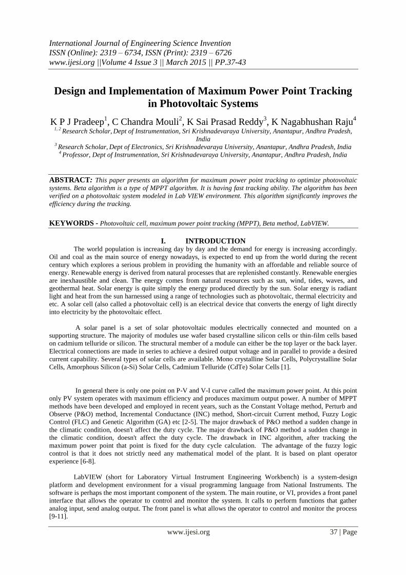
II. SYSTEM DESCRIPTION The block diagram of general MPPT Photo Voltaic system is shown in the following figure. The
photovoltaic Output voltage and current are given to MPPT algorithm and DC/DC converter. The algorithm
used is to calculate the duty cycle for the converter in different irradiation level.
Fig - 1 Block Diagram of General MPPT System
III. MPPT ALGORITHM Beta is a variable used to find the intermediate value between current and voltage. Beta is calculated by
using the following equation.
ln (Ipv /Vpv ) – C. Vpv = ln (I0.C) = 𝛽
Where Ipv denotes panel output current, Vpv denotes panel output voltage. C denotes conductance, is calculated
by using
C=q /(𝜂 𝐾 𝑇 𝑁𝑠)
Where q denotes the electron charge (charge carried out by single electron or photon 1.602176565 (35)
x
10-19
coulombs), 𝜂 denotes the quality factor of the junction panel, K denotes the Boltzmann constant
(1.380648813x 10⁻²³ J/K), T represent the temperature, and NS represent number of cells in series. It may be
noted that 𝛽 is independent of insolation but depends on temperature [12].
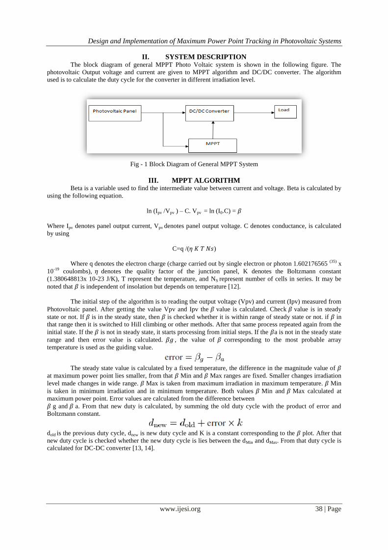
The initial step of the algorithm is to reading the output voltage (Vpv) and current (Ipv) measured from
Photovoltaic panel. After getting the value Vpv and Ipv the 𝛽 value is calculated. Check 𝛽 value is in steady
state or not. If 𝛽 is in the steady state, then 𝛽 is checked whether it is within range of steady state or not. if 𝛽 in
that range then it is switched to Hill climbing or other methods. After that same process repeated again from the
initial state. If the 𝛽 is not in steady state, it starts processing from initial steps. If the 𝛽a is not in the steady state
range and then error value is calculated. 𝛽𝑔 , the value of 𝛽 corresponding to the most probable array
temperature is used as the guiding value.
The steady state value is calculated by a fixed temperature, the difference in the magnitude value of 𝛽
at maximum power point lies smaller, from that 𝛽 Min and 𝛽 Max ranges are fixed. Smaller changes irradiation
level made changes in wide range. 𝛽 Max is taken from maximum irradiation in maximum temperature. 𝛽 Min
is taken in minimum irradiation and in minimum temperature. Both values 𝛽 Min and 𝛽 Max calculated at
maximum power point. Error values are calculated from the difference between
𝛽 g and 𝛽 a. From that new duty is calculated, by summing the old duty cycle with the product of error and
Boltzmann constant.
dold is the previous duty cycle, dnew is new duty cycle and K is a constant corresponding to the 𝛽 plot. After that
new duty cycle is checked whether the new duty cycle is lies between the dMin and dMax. From that duty cycle is
calculated for DC-DC converter [13, 14].
Design and Implementation of Maximum Power Point Tracking in Photovoltaic Systems
www.ijesi.org 39 | Page
Fig – 2. Flowchart of the Beta Method
IV. SIMULATION OF THE PROPOSED ALGORITHM
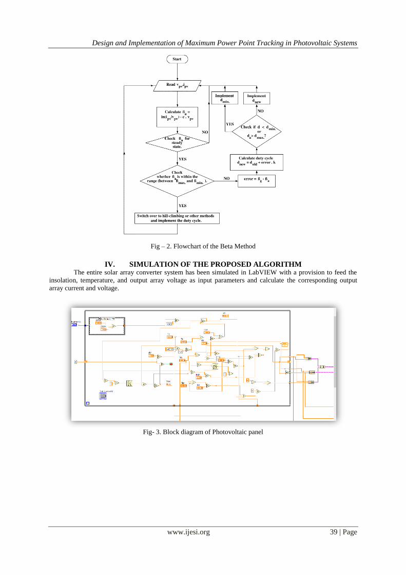
The entire solar array converter system has been simulated in LabVIEW with a provision to feed the
insolation, temperature, and output array voltage as input parameters and calculate the corresponding output
array current and voltage.
Fig- 3. Block diagram of Photovoltaic panel
Design and Implementation of Maximum Power Point Tracking in Photovoltaic Systems
www.ijesi.org 40 | Page
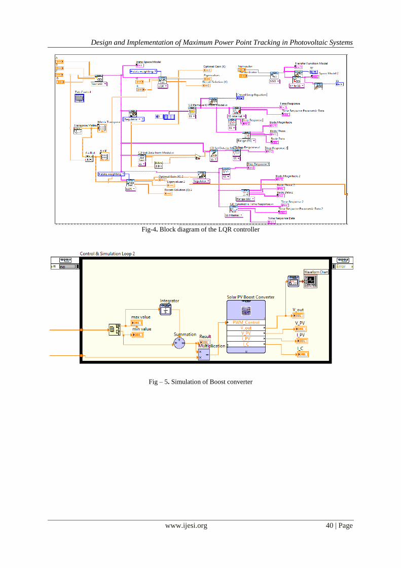
Fig-4. Block diagram of the LQR controller
Fig – 5. Simulation of Boost converter
Design and Implementation of Maximum Power Point Tracking in Photovoltaic Systems
www.ijesi.org 41 | Page
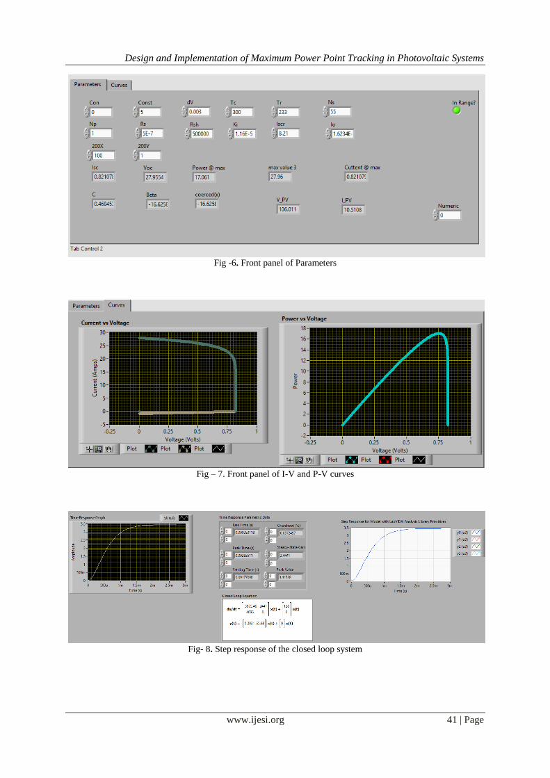
Fig -6. Front panel of Parameters
Fig – 7. Front panel of I-V and P-V curves
Fig- 8. Step response of the closed loop system
Design and Implementation of Maximum Power Point Tracking in Photovoltaic Systems
www.ijesi.org 42 | Page
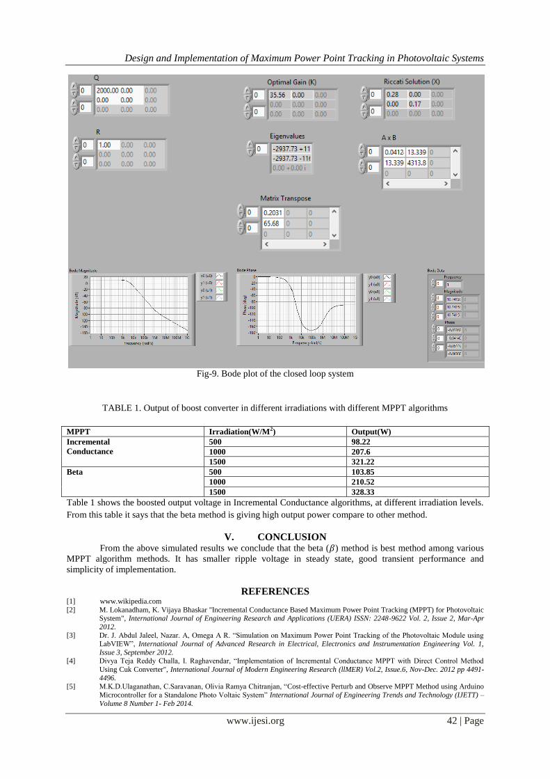
Fig-9. Bode plot of the closed loop system
TABLE 1. Output of boost converter in different irradiations with different MPPT algorithms
MPPT Irradiation(W/M2) Output(W)
Incremental
Conductance
500 98.22
1000 207.6
1500 321.22
Beta 500 103.85
1000 210.52
1500 328.33
Table 1 shows the boosted output voltage in Incremental Conductance algorithms, at different irradiation levels.
From this table it says that the beta method is giving high output power compare to other method.
V. CONCLUSION From the above simulated results we conclude that the beta (𝛽) method is best method among various
MPPT algorithm methods. It has smaller ripple voltage in steady state, good transient performance and
simplicity of implementation.
REFERENCES [1] www.wikipedia.com
[2] M. Lokanadham, K. Vijaya Bhaskar "Incremental Conductance Based Maximum Power Point Tracking (MPPT) for Photovoltaic System", International Journal of Engineering Research and Applications (UERA) ISSN: 2248-9622 Vol. 2, Issue 2, Mar-Apr
2012. [3] Dr. J. Abdul Jaleel, Nazar. A, Omega A R. “Simulation on Maximum Power Point Tracking of the Photovoltaic Module using
LabVIEW”, International Journal of Advanced Research in Electrical, Electronics and Instrumentation Engineering Vol. 1,
Issue 3, September 2012. [4] Divya Teja Reddy Challa, I. Raghavendar, “Implementation of Incremental Conductance MPPT with Direct Control Method
Using Cuk Converter", International Journal of Modern Engineering Research (llMER) Vol.2, Issue.6, Nov-Dec. 2012 pp 4491-
4496. [5] M.K.D.Ulaganathan, C.Saravanan, Olivia Ramya Chitranjan, “Cost-effective Perturb and Observe MPPT Method using Arduino
Microcontroller for a Standalone Photo Voltaic System” International Journal of Engineering Trends and Technology (IJETT) –
Volume 8 Number 1- Feb 2014.
Design and Implementation of Maximum Power Point Tracking in Photovoltaic Systems
www.ijesi.org 43 | Page
[6] Roshan Kini , Geetha.Narayanan , Aditya Dalvi, “COMPARATIVE STUDY AND IMPLEMENTATION OF INCREMENTAL
CONDUCTANCE METHOD AND PERTURB AND OBSERVE METHOD WITH BUCK CONVERTER BY USING ARDUINO”, IJRET: International Journal of Research in Engineering and Technology . Volume: 03 Issue: 01 | Jan-2014.
[7] Safari A, Mekhilef S, “Simulation and Hardware Implementation of Incremental Conductance MPPT with Direct Control
Method Using Cuk Converter”, IEEE Trans,March 2010. [8] Zolkapli, M. ; AI-Junid S. A. M.; Othman Z.; Manut, A.; Mohd Zulkifli M. A, “High-Efficiency Dual-Axis Solar Tracking
Developement using Arduino” 2013 International Conference on Technology, Informatics, Management, Engineering &
Environment (TIME-E 2013)Bandung, Indonesia, June 23-26,2013. [9] www.ni.com
[10] Gary W. Johnson, Richard Jennings, “LabVIEW Graphical Programming”, 4th ed. McGraw-Hill.
[11] Cor J. Kalkman “LabVIEW : A software system for data acquisition, data analysis and instrument control” Journal of Clinical Monitoring and Computing, 2005, P.51-58.
[12] Sachin Jain, and Vivek Agarwal, “A New Algorithm for Rapid Tracking of Approximate Maximum Power Point in Photovoltaic
Systems" IEEE POWER ELECTRONICS LETTERS, VOL. 2, NO. I, MARCH 2004. [13] DineshKumar. T, Subramani. M, “Design and Implementation Maximum Power Point Tracking in Photovoltaic Cells” Energy
Efficient Technologies for Sustainability (ICEETS), 2013.
[14] Moacyr A. G. de Brito, Leonardo P. Sampaio, Luigi G. Jr., Guilherme A. e Melo, Carlos A. Canesin, “Comparative Analysis of MPPT Techniques for PV Applications”
Recommended

![Optimised Photovoltaic Solar Charger With Voltage … · Optimised Photovoltaic Solar Charger With Voltage Maximum Power Point Tracking ... MPPT) [5]. The main goal of this thesis](https://img.pdfslide.net/doc/110x75/5b5c96607f8b9ac8618c8870/optimised-photovoltaic-solar-charger-with-voltage-optimised-photovoltaic-solar.jpg)