MAE 305LDesign ProjectDesign ProjectPreliminary Report
14 September 2011
Dr. KunzRm. 105F301-4061
Overall Goals
• The Design Project assignment you received today (along with this briefing) constitutes a Request for Proposals (RFP)– Statement of the problem that the customer wants you to
address– Detailed requirements: the successful solution to the problem
must satisfy all these requirementsmust satisfy all these requirements
• Each team is being asked to respond to this RFP– Preliminary Design Report – your team’s proposed solution to
the problem (Due 3 October 2011, 2:00 pm)– Final Design Report – detailed design and instructions for use
(Due 26 October, 2:00 pm)– Demonstration and delivery of the finished article (7 December
2011)
2
Preliminary Design Report (PDR)
• The PDR is a proposal to the customer• The PDR should communicate to the customer that your
team:– Understands the problem and the requirements– Has a solution that will solve the problem and address all the
requirementsrequirements
• Ultimate goal of the PDR is to convince the customer that you have a solution that is worth pursuing to the next phase (detail design)
3
PDR Format
• The PDR must be organized according to the outline below:– Cover Sheet– Introduction and Summary– Problem Definition– Design Concept Description– Design Concept Analysis– Design Concept Analysis– Conclusions
• Each of these elements must be in this order and begin on a new page
• Additional details on some elements are given in the following
4
Cover Page
• Contents are:– Title, something like
Tool Maker’s Vise Jaw Fabrication FixtureA Preliminary Design Proposal submitted to:
– Customer names– Course number and name– Semester– Submitted by:
Names of team members
– Date
5
Problem Definition
• Problem Definition section shall include:– General statement of the problem– Detailed requirements– Any additional considerations arising from your understanding of
the problem
• Don’t hesitate to use the same words used by the • Don’t hesitate to use the same words used by the customer in the RFP
• Include a drawing of the part your fixture is designed to produce
6
Design Concept Description
• Contains a clear, concise description of your proposed solution– Describe in general terms the configuration of your preliminary
fixture design– Describe specifically how your fixture will be used to make the
part• Major components and the function of each• Refer to the labeled drawing of the part• Refer to the labeled drawing of the part• Refer to labeled sketch(es) of your preliminary design solution
– Describe how your design addresses each of the customer requirements
• Use of reference points to generate reproducible tool paths• Accurate location of blank in fixture• Accurate location of fixture on milling machine table• Clearance between cutter and fixture• etc.
– Be sure to consider the availability of materials in the shop
7
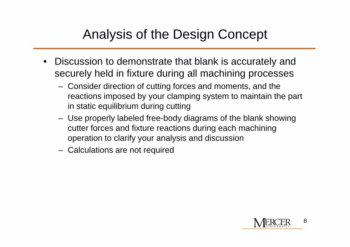
Analysis of the Design Concept
• Discussion to demonstrate that blank is accurately and securely held in fixture during all machining processes– Consider direction of cutting forces and moments, and the
reactions imposed by your clamping system to maintain the part in static equilibrium during cutting
– Use properly labeled free-body diagrams of the blank showing cutter forces and fixture reactions during each machining cutter forces and fixture reactions during each machining operation to clarify your analysis and discussion
– Calculations are not required
8
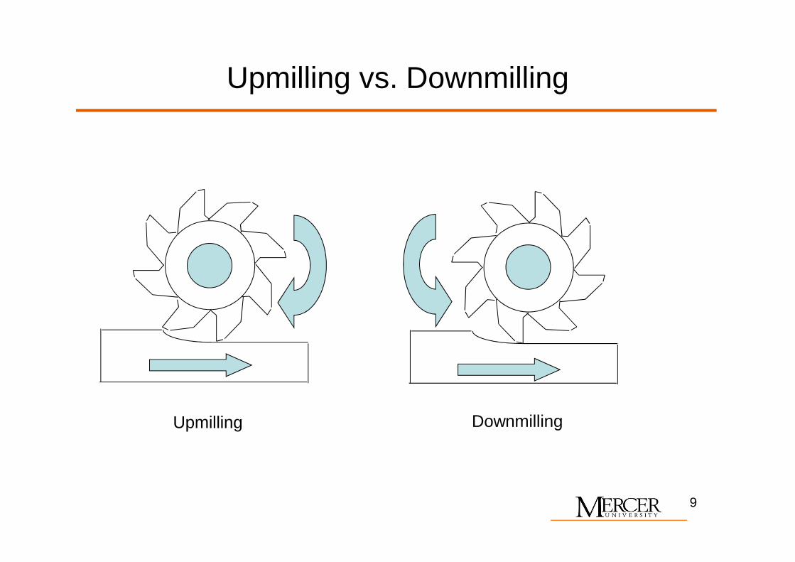
Upmilling vs. Downmilling
Upmilling Downmilling
9
Use of Sketches
• Sketches are informal drawings• Used as an overview to convey general concepts and
assist in visualization, usually in isometric view• Intent is not to provide all the detail needed to build the
fixture• Sketches are suitable and appropriate for PDR• Should be computer-generated• Must be neat, clear, and labeled as needed• Intended to clarify the written descriptions
10
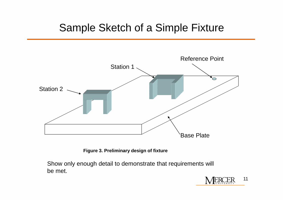
Sample Sketch of a Simple Fixture
Station 1
Station 2
Reference Point
Base Plate
Show only enough detail to demonstrate that requirements will be met.
Figure 3. Preliminary design of fixture
11
Summary
• The PDR communicates your understanding of the problem, and your proposed solution to the problem– Organized in conformance with customer requirements as
described herein– Neat– Concise– Concise– Contain sketches/figures as needed to illuminate key points
12
Recommended