DF–54 DIFFERENTIAL – REAR DIFFERENTIAL CARRIER ASSEMBLY
DF
INSPECTION1. INSPECT DIFFERENTIAL PINION AND SIDE GEAR
(a) Check that there is no damage to the differential pinion or differential side gear.If the differential pinion and/or differential side gear is damaged, replace the differential.
2. INSPECT DIFFERENTIAL CASE(a) Check that the differential case is not damaged.
If the differential case is damaged, replace it.REASSEMBLY1. ASSEMBLE DIFFERENTIAL CASE
(a) Install the rear differential side gear thrust washer onto the rear differential side gear.
(b) Install the rear differential pinion thrust washer and rear differential pinion onto the rear differential spider.
(c) Fix the differential case RH.
(d) Install the rear differential side gear and rear differential spider onto the differential case RH.
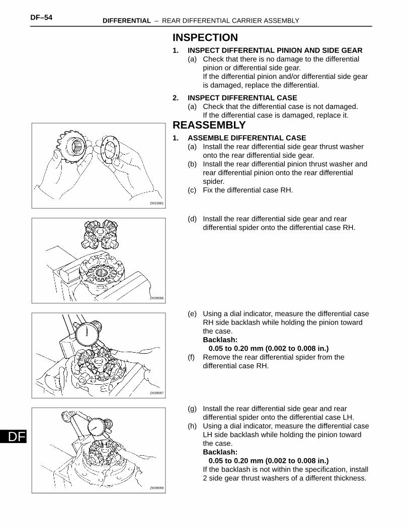
(e) Using a dial indicator, measure the differential case RH side backlash while holding the pinion toward the case.Backlash:
0.05 to 0.20 mm (0.002 to 0.008 in.)(f) Remove the rear differential spider from the
differential case RH.
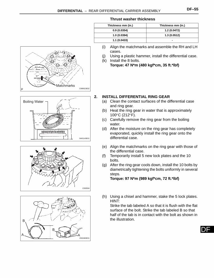
(g) Install the rear differential side gear and rear differential spider onto the differential case LH.
(h) Using a dial indicator, measure the differential case LH side backlash while holding the pinion toward the case.Backlash:
0.05 to 0.20 mm (0.002 to 0.008 in.)If the backlash is not within the specification, install 2 side gear thrust washers of a different thickness.
ZK01881
ZK09096
ZK09097
ZK09098
DIFFERENTIAL – REAR DIFFERENTIAL CARRIER ASSEMBLY DF–55
F
DThrust washer thickness
(i) Align the matchmarks and assemble the RH and LH cases.
(j) Using a plastic hammer, install the differential case.(k) Install the 8 bolts.
Torque: 47 N*m (480 kgf*cm, 35 ft.*lbf)
2. INSTALL DIFFERENTIAL RING GEAR(a) Clean the contact surfaces of the differential case
and ring gear.(b) Heat the ring gear in water that is approximately
100°C (212°F).(c) Carefully remove the ring gear from the boiling
water.(d) After the moisture on the ring gear has completely
evaporated, quickly install the ring gear onto the differential case.
(e) Align the matchmarks on the ring gear with those of the differential case.
(f) Temporarily install 5 new lock plates and the 10 bolts.
(g) After the ring gear cools down, install the 10 bolts by diametrically tightening the bolts uniformly in several steps.Torque: 97 N*m (989 kgf*cm, 72 ft.*lbf)
(h) Using a chisel and hammer, stake the 5 lock plates.HINT:Strike the tab labeled A so that it is flush with the flat surface of the bolt. Strike the tab labeled B so that half of the tab is in contact with the bolt as shown in the illustration.
Thickness mm (in.) Thickness mm (in.)
0.9 (0.0354) 1.2 (0.0472)
1.0 (0.0394) 1.3 (0.0512)
1.1 (0.0433) -
MatchmarksC089323E02
Boiling Water
SA01143E01
C093504
A AB
B
Z002483E01
DF–56 DIFFERENTIAL – REAR DIFFERENTIAL CARRIER ASSEMBLY
DF
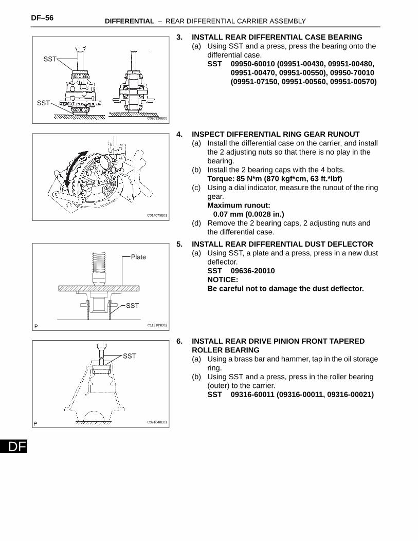
3. INSTALL REAR DIFFERENTIAL CASE BEARING(a) Using SST and a press, press the bearing onto the
differential case.SST 09950-60010 (09951-00430, 09951-00480,
09951-00470, 09951-00550), 09950-70010 (09951-07150, 09951-00560, 09951-00570)
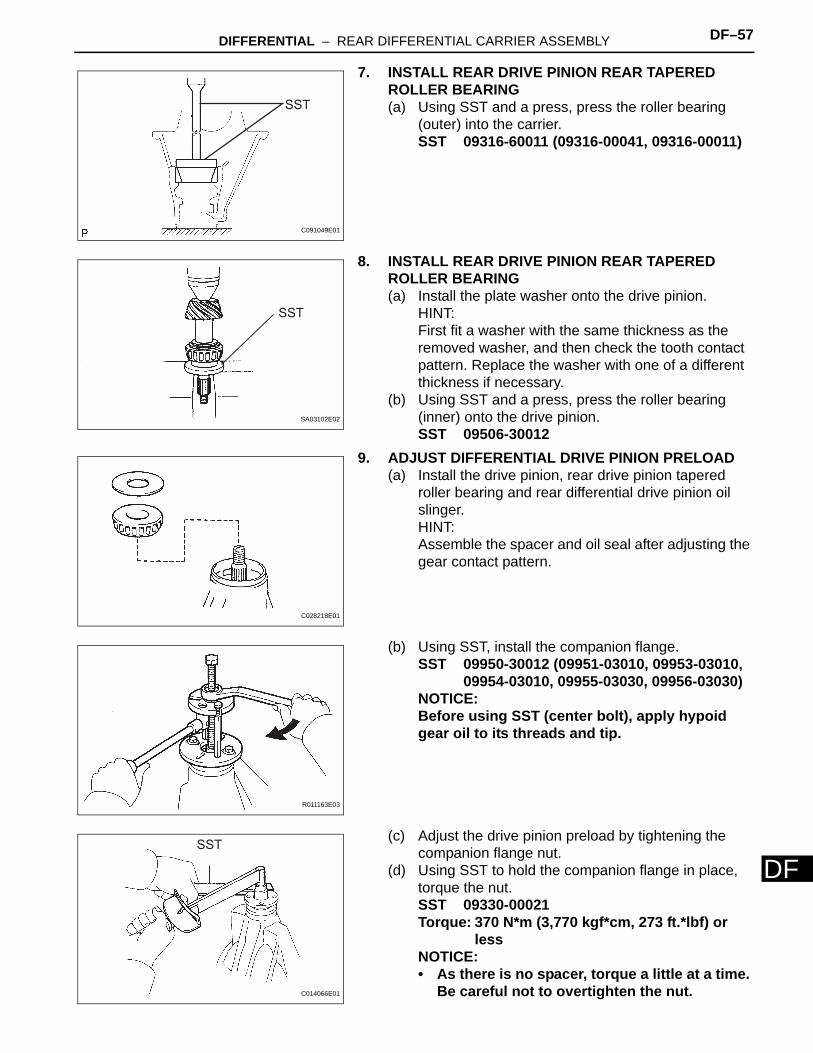
4. INSPECT DIFFERENTIAL RING GEAR RUNOUT(a) Install the differential case on the carrier, and install
the 2 adjusting nuts so that there is no play in the bearing.
(b) Install the 2 bearing caps with the 4 bolts.Torque: 85 N*m (870 kgf*cm, 63 ft.*lbf)
(c) Using a dial indicator, measure the runout of the ring gear.Maximum runout:
0.07 mm (0.0028 in.)(d) Remove the 2 bearing caps, 2 adjusting nuts and
the differential case.5. INSTALL REAR DIFFERENTIAL DUST DEFLECTOR
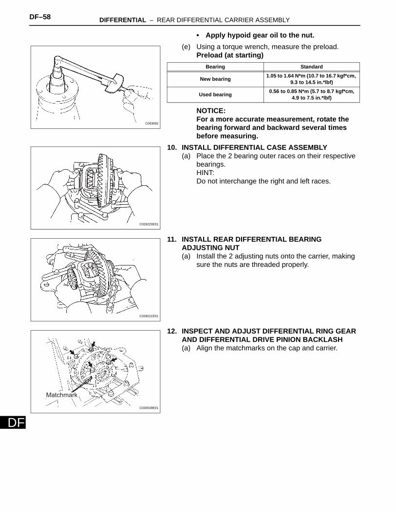
(a) Using SST, a plate and a press, press in a new dust deflector.SST 09636-20010NOTICE:Be careful not to damage the dust deflector.
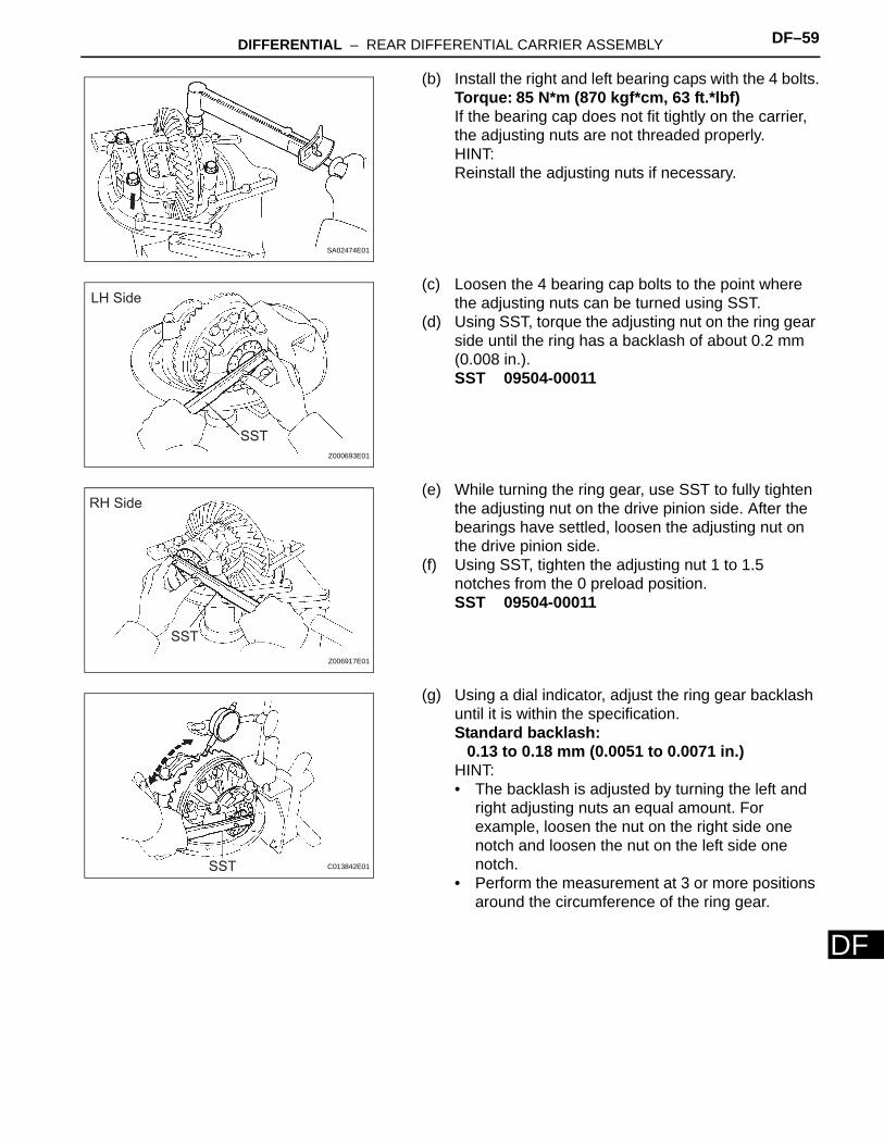
6. INSTALL REAR DRIVE PINION FRONT TAPERED ROLLER BEARING(a) Using a brass bar and hammer, tap in the oil storage
ring.(b) Using SST and a press, press in the roller bearing
(outer) to the carrier.SST 09316-60011 (09316-00011, 09316-00021)
SST
SST
C090326E05
C014075E01
Plate
SST
C113183E02
SST
C091048E01
DIFFERENTIAL – REAR DIFFERENTIAL CARRIER ASSEMBLY DF–57
F
D7. INSTALL REAR DRIVE PINION REAR TAPERED ROLLER BEARING(a) Using SST and a press, press the roller bearing
(outer) into the carrier.SST 09316-60011 (09316-00041, 09316-00011)
8. INSTALL REAR DRIVE PINION REAR TAPERED ROLLER BEARING(a) Install the plate washer onto the drive pinion.
HINT:First fit a washer with the same thickness as the removed washer, and then check the tooth contact pattern. Replace the washer with one of a different thickness if necessary.
(b) Using SST and a press, press the roller bearing (inner) onto the drive pinion.SST 09506-30012
9. ADJUST DIFFERENTIAL DRIVE PINION PRELOAD(a) Install the drive pinion, rear drive pinion tapered
roller bearing and rear differential drive pinion oil slinger.HINT:Assemble the spacer and oil seal after adjusting the gear contact pattern.
(b) Using SST, install the companion flange.SST 09950-30012 (09951-03010, 09953-03010,
09954-03010, 09955-03030, 09956-03030)NOTICE:Before using SST (center bolt), apply hypoid gear oil to its threads and tip.
(c) Adjust the drive pinion preload by tightening the companion flange nut.
(d) Using SST to hold the companion flange in place, torque the nut.SST 09330-00021Torque: 370 N*m (3,770 kgf*cm, 273 ft.*lbf) or
lessNOTICE:• As there is no spacer, torque a little at a time.
Be careful not to overtighten the nut.
SST
C091049E01
SST
SA03102E02
C028218E01
R011163E03
SST
C014066E01
DF–58 DIFFERENTIAL – REAR DIFFERENTIAL CARRIER ASSEMBLY
DF
• Apply hypoid gear oil to the nut.(e) Using a torque wrench, measure the preload.
Preload (at starting)
NOTICE:For a more accurate measurement, rotate the bearing forward and backward several times before measuring.
10. INSTALL DIFFERENTIAL CASE ASSEMBLY(a) Place the 2 bearing outer races on their respective
bearings.HINT:Do not interchange the right and left races.
11. INSTALL REAR DIFFERENTIAL BEARING ADJUSTING NUT(a) Install the 2 adjusting nuts onto the carrier, making
sure the nuts are threaded properly.
12. INSPECT AND ADJUST DIFFERENTIAL RING GEAR AND DIFFERENTIAL DRIVE PINION BACKLASH(a) Align the matchmarks on the cap and carrier.
C003092
Bearing Standard
New bearing 1.05 to 1.64 N*m (10.7 to 16.7 kgf*cm, 9.3 to 14.5 in.*lbf)
Used bearing 0.56 to 0.85 N*m (5.7 to 8.7 kgf*cm, 4.9 to 7.5 in.*lbf)
C028220E01
C028221E01
Matchmark
C030539E01
DIFFERENTIAL – REAR DIFFERENTIAL CARRIER ASSEMBLY DF–59
F
D(b) Install the right and left bearing caps with the 4 bolts.Torque: 85 N*m (870 kgf*cm, 63 ft.*lbf)If the bearing cap does not fit tightly on the carrier, the adjusting nuts are not threaded properly.HINT:Reinstall the adjusting nuts if necessary.
(c) Loosen the 4 bearing cap bolts to the point where the adjusting nuts can be turned using SST.
(d) Using SST, torque the adjusting nut on the ring gear side until the ring has a backlash of about 0.2 mm (0.008 in.).SST 09504-00011
(e) While turning the ring gear, use SST to fully tighten the adjusting nut on the drive pinion side. After the bearings have settled, loosen the adjusting nut on the drive pinion side.
(f) Using SST, tighten the adjusting nut 1 to 1.5 notches from the 0 preload position.SST 09504-00011
(g) Using a dial indicator, adjust the ring gear backlash until it is within the specification.Standard backlash:
0.13 to 0.18 mm (0.0051 to 0.0071 in.)HINT:• The backlash is adjusted by turning the left and
right adjusting nuts an equal amount. For example, loosen the nut on the right side one notch and loosen the nut on the left side one notch.
• Perform the measurement at 3 or more positions around the circumference of the ring gear.
SA02474E01
SST
LH Side
Z000693E01
SST
RH Side
Z006917E01
SST C013842E01
DF–60 DIFFERENTIAL – REAR DIFFERENTIAL CARRIER ASSEMBLY
DF
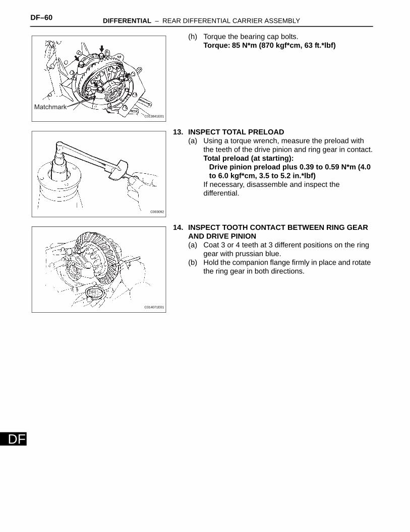
(h) Torque the bearing cap bolts.Torque: 85 N*m (870 kgf*cm, 63 ft.*lbf)
13. INSPECT TOTAL PRELOAD(a) Using a torque wrench, measure the preload with
the teeth of the drive pinion and ring gear in contact.Total preload (at starting):
Drive pinion preload plus 0.39 to 0.59 N*m (4.0 to 6.0 kgf*cm, 3.5 to 5.2 in.*lbf)
If necessary, disassemble and inspect the differential.
14. INSPECT TOOTH CONTACT BETWEEN RING GEAR AND DRIVE PINION(a) Coat 3 or 4 teeth at 3 different positions on the ring
gear with prussian blue.(b) Hold the companion flange firmly in place and rotate
the ring gear in both directions.
MatchmarkC013841E01
C003092
C014071E01
DIFFERENTIAL – REAR DIFFERENTIAL CARRIER ASSEMBLY DF–61
F
D(c) Inspect the tooth contact pattern.
DF–62 DIFFERENTIAL – REAR DIFFERENTIAL CARRIER ASSEMBLY
DF
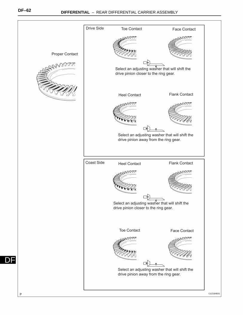
Proper Contact
Drive Side Toe Contact Face Contact
Select an adjusting washer that will shift the drive pinion closer to the ring gear.
Heel Contact Flank Contact
Select an adjusting washer that will shift the drive pinion away from the ring gear.
Coast Side Heel Contact Flank Contact
Toe Contact Face Contact
Select an adjusting washer that will shift the drive pinion closer to the ring gear.
Select an adjusting washer that will shift the drive pinion away from the ring gear.
C113184E01
DIFFERENTIAL – REAR DIFFERENTIAL CARRIER ASSEMBLY DF–63
F
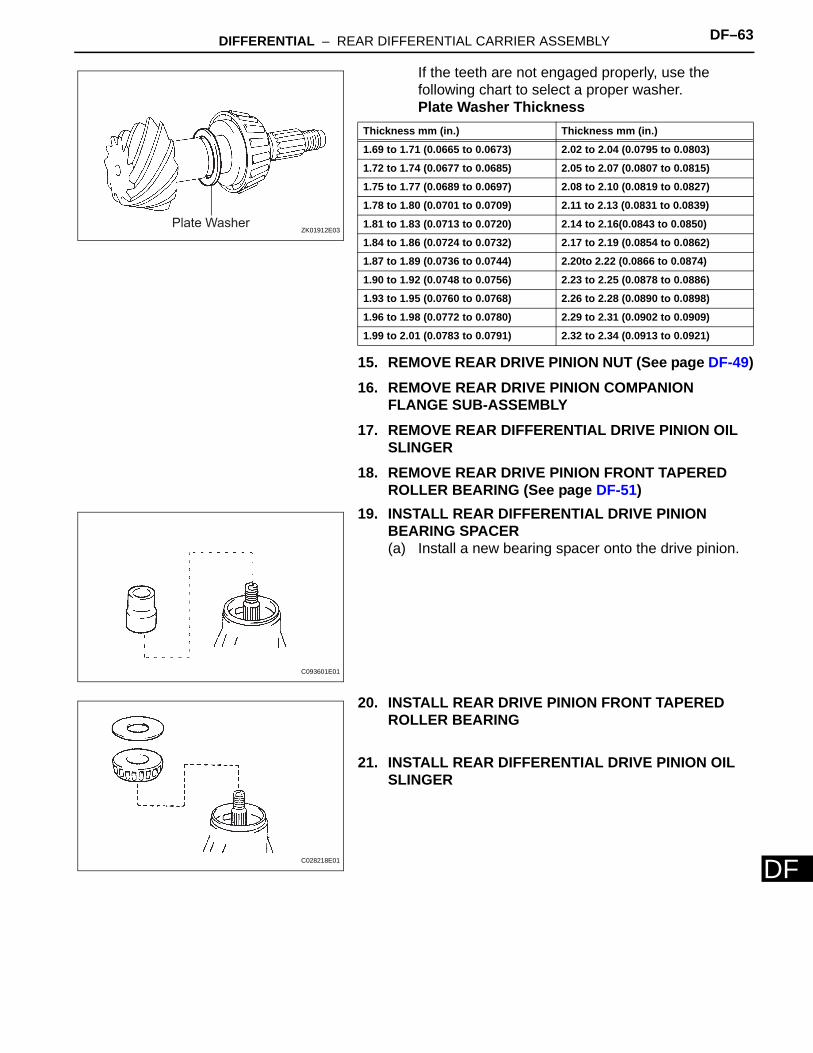
DIf the teeth are not engaged properly, use the following chart to select a proper washer.Plate Washer Thickness
15. REMOVE REAR DRIVE PINION NUT (See page DF-49)16. REMOVE REAR DRIVE PINION COMPANION
FLANGE SUB-ASSEMBLY17. REMOVE REAR DIFFERENTIAL DRIVE PINION OIL
SLINGER18. REMOVE REAR DRIVE PINION FRONT TAPERED
ROLLER BEARING (See page DF-51)19. INSTALL REAR DIFFERENTIAL DRIVE PINION
BEARING SPACER(a) Install a new bearing spacer onto the drive pinion.
20. INSTALL REAR DRIVE PINION FRONT TAPERED ROLLER BEARING
21. INSTALL REAR DIFFERENTIAL DRIVE PINION OIL SLINGER
Plate WasherZK01912E03
Thickness mm (in.) Thickness mm (in.)
1.69 to 1.71 (0.0665 to 0.0673) 2.02 to 2.04 (0.0795 to 0.0803)
1.72 to 1.74 (0.0677 to 0.0685) 2.05 to 2.07 (0.0807 to 0.0815)
1.75 to 1.77 (0.0689 to 0.0697) 2.08 to 2.10 (0.0819 to 0.0827)
1.78 to 1.80 (0.0701 to 0.0709) 2.11 to 2.13 (0.0831 to 0.0839)
1.81 to 1.83 (0.0713 to 0.0720) 2.14 to 2.16(0.0843 to 0.0850)
1.84 to 1.86 (0.0724 to 0.0732) 2.17 to 2.19 (0.0854 to 0.0862)
1.87 to 1.89 (0.0736 to 0.0744) 2.20to 2.22 (0.0866 to 0.0874)
1.90 to 1.92 (0.0748 to 0.0756) 2.23 to 2.25 (0.0878 to 0.0886)
1.93 to 1.95 (0.0760 to 0.0768) 2.26 to 2.28 (0.0890 to 0.0898)
1.96 to 1.98 (0.0772 to 0.0780) 2.29 to 2.31 (0.0902 to 0.0909)
1.99 to 2.01 (0.0783 to 0.0791) 2.32 to 2.34 (0.0913 to 0.0921)
C093601E01
C028218E01
DF–64 DIFFERENTIAL – REAR DIFFERENTIAL CARRIER ASSEMBLY
DF
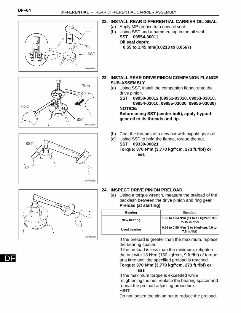
22. INSTALL REAR DIFFERENTIAL CARRIER OIL SEAL(a) Apply MP grease to a new oil seal.(b) Using SST and a hammer, tap in the oil seal.
SST 09554-30011Oil seal depth:
0.55 to 1.45 mm(0.0213 to 0.0567)
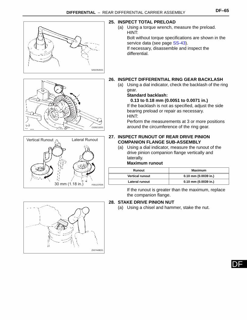
23. INSTALL REAR DRIVE PINION COMPANION FLANGE SUB-ASSEMBLY(a) Using SST, install the companion flange onto the
drive pinion.SST 09950-30012 (09951-03010, 09953-03010,
09954-03010, 09955-03030, 09956-03030)NOTICE:Before using SST (center bolt), apply hypoid gear oil to its threads and tip.
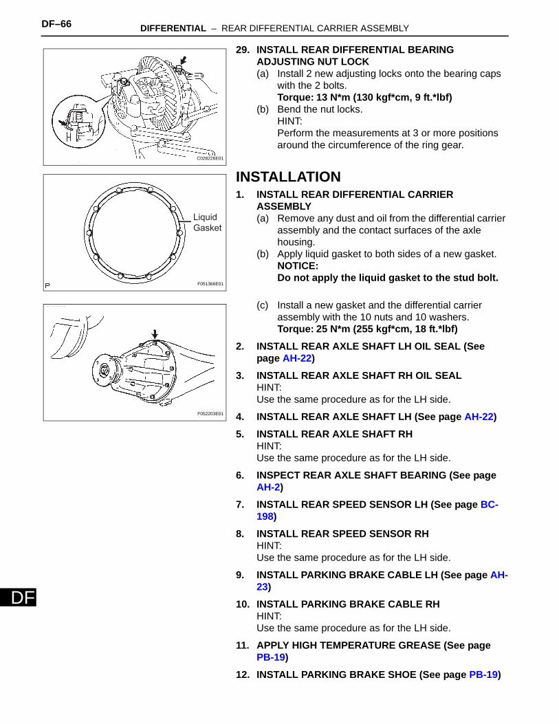
(b) Coat the threads of a new nut with hypoid gear oil.(c) Using SST to hold the flange, torque the nut.
SST 09330-00021Torque: 370 N*m (3,770 kgf*cm, 273 ft.*lbf) or
less
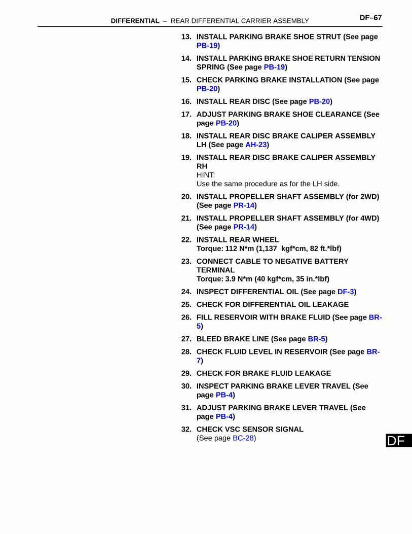
24. INSPECT DRIVE PINION PRELOAD(a) Using a torque wrench, measure the preload of the
backlash between the drive pinion and ring gear.Preload (at starting)
If the preload is greater than the maximum, replace the bearing spacer.If the preload is less than the minimum, retighten the nut with 13 N*m (130 kgf*cm, 9 ft.*lbf) of torque at a time until the specified preload is reached.Torque: 370 N*m (3,770 kgf*cm, 273 ft.*lbf) or
lessIf the maximum torque is exceeded while retightening the nut, replace the bearing spacer and repeat the preload adjusting procedure.HINT:Do not loosen the pinion nut to reduce the preload.
SST
Z000698E01
Hold
SST
Turn
R011163E02
SST
SA02351E03
SA02352E01
Bearing Standard
New bearing 1.05 to 1.64 N*m (11 to 17 kgf*cm, 9.3 to 15 in.*lbf)
Used bearing 0.56 to 0.85 N*m (6 to 9 kgf*cm, 4.9 to 7.5 in.*lbf)
DIFFERENTIAL – REAR DIFFERENTIAL CARRIER ASSEMBLY DF–65
F
D25. INSPECT TOTAL PRELOAD(a) Using a torque wrench, measure the preload.
HINT:Bolt without torque specifications are shown in the service data (see page SS-43).If necessary, disassemble and inspect the differential.
26. INSPECT DIFFERENTIAL RING GEAR BACKLASH(a) Using a dial indicator, check the backlash of the ring
gear.Standard backlash:
0.13 to 0.18 mm (0.0051 to 0.0071 in.)If the backlash is not as specified, adjust the side bearing preload or repair as necessary.HINT:Perform the measurements at 3 or more positions around the circumference of the ring gear.
27. INSPECT RUNOUT OF REAR DRIVE PINION COMPANION FLANGE SUB-ASSEMBLY(a) Using a dial indicator, measure the runout of the
drive pinion companion flange vertically and laterally.Maximum runout
If the runout is greater than the maximum, replace the companion flange.
28. STAKE DRIVE PINION NUT(a) Using a chisel and hammer, stake the nut.
SA02352E01
C028211E01
Vertical Runout Lateral Runout
30 mm (1.18 in.) F001237E05
Runout Maximum
Vertical runout 0.10 mm (0.0039 in.)
Lateral runout 0.10 mm (0.0039 in.)
ZK07449E01
DF–66 DIFFERENTIAL – REAR DIFFERENTIAL CARRIER ASSEMBLY
DF
29. INSTALL REAR DIFFERENTIAL BEARING ADJUSTING NUT LOCK(a) Install 2 new adjusting locks onto the bearing caps
with the 2 bolts.Torque: 13 N*m (130 kgf*cm, 9 ft.*lbf)
(b) Bend the nut locks.HINT:Perform the measurements at 3 or more positions around the circumference of the ring gear.
INSTALLATION1. INSTALL REAR DIFFERENTIAL CARRIER
ASSEMBLY(a) Remove any dust and oil from the differential carrier
assembly and the contact surfaces of the axle housing.
(b) Apply liquid gasket to both sides of a new gasket.NOTICE:Do not apply the liquid gasket to the stud bolt.
(c) Install a new gasket and the differential carrier assembly with the 10 nuts and 10 washers.Torque: 25 N*m (255 kgf*cm, 18 ft.*lbf)
2. INSTALL REAR AXLE SHAFT LH OIL SEAL (See page AH-22)
3. INSTALL REAR AXLE SHAFT RH OIL SEALHINT:Use the same procedure as for the LH side.
4. INSTALL REAR AXLE SHAFT LH (See page AH-22)5. INSTALL REAR AXLE SHAFT RH
HINT:Use the same procedure as for the LH side.
6. INSPECT REAR AXLE SHAFT BEARING (See page AH-2)
7. INSTALL REAR SPEED SENSOR LH (See page BC-198)
8. INSTALL REAR SPEED SENSOR RHHINT:Use the same procedure as for the LH side.
9. INSTALL PARKING BRAKE CABLE LH (See page AH-23)
10. INSTALL PARKING BRAKE CABLE RHHINT:Use the same procedure as for the LH side.
11. APPLY HIGH TEMPERATURE GREASE (See page PB-19)
12. INSTALL PARKING BRAKE SHOE (See page PB-19)
C028226E01
Liquid Gasket
F051366E01
F052203E01
DIFFERENTIAL – REAR DIFFERENTIAL CARRIER ASSEMBLY DF–67
F
D13. INSTALL PARKING BRAKE SHOE STRUT (See page PB-19)
14. INSTALL PARKING BRAKE SHOE RETURN TENSION SPRING (See page PB-19)
15. CHECK PARKING BRAKE INSTALLATION (See page PB-20)
16. INSTALL REAR DISC (See page PB-20)17. ADJUST PARKING BRAKE SHOE CLEARANCE (See
page PB-20)18. INSTALL REAR DISC BRAKE CALIPER ASSEMBLY
LH (See page AH-23)19. INSTALL REAR DISC BRAKE CALIPER ASSEMBLY
RHHINT:Use the same procedure as for the LH side.
20. INSTALL PROPELLER SHAFT ASSEMBLY (for 2WD) (See page PR-14)
21. INSTALL PROPELLER SHAFT ASSEMBLY (for 4WD) (See page PR-14)
22. INSTALL REAR WHEELTorque: 112 N*m (1,137 kgf*cm, 82 ft.*lbf)
23. CONNECT CABLE TO NEGATIVE BATTERY TERMINALTorque: 3.9 N*m (40 kgf*cm, 35 in.*lbf)
24. INSPECT DIFFERENTIAL OIL (See page DF-3)25. CHECK FOR DIFFERENTIAL OIL LEAKAGE26. FILL RESERVOIR WITH BRAKE FLUID (See page BR-
5)27. BLEED BRAKE LINE (See page BR-5)28. CHECK FLUID LEVEL IN RESERVOIR (See page BR-
7)29. CHECK FOR BRAKE FLUID LEAKAGE30. INSPECT PARKING BRAKE LEVER TRAVEL (See
page PB-4)31. ADJUST PARKING BRAKE LEVER TRAVEL (See
page PB-4)32. CHECK VSC SENSOR SIGNAL
(See page BC-28)
Recommended