Project Objective Development of an electrically small antenna, capable of ~ 1 MW cw power output, tunable from ~ 3 to 10 MHz
Accomplishments / Progress • Experimental verification of antenna
concept and tuning capability at 100 MHz (30 MHz to 100 MHz)
• Experimental demonstration of full size antenna at 10 MHz (limited tuning range from 9.5 to 10 MHz)
• Verified conventional antenna drive (sinusoidal source through 50 Ohm coax)
• Verified direct drive approach • Radiated ~ 500 W at 10 MHz with
approx. 90% efficiency (relative to DC power input)
• Transportable “HAARP” scale-up
Electrically Small Antennas
COLLABORATIVE RESEARCH ON NOVEL HIGH POWER SOURCES FOR AND PHYSICS OF IONOSPHERIC MODIFICATION
Electrically Small Antenna
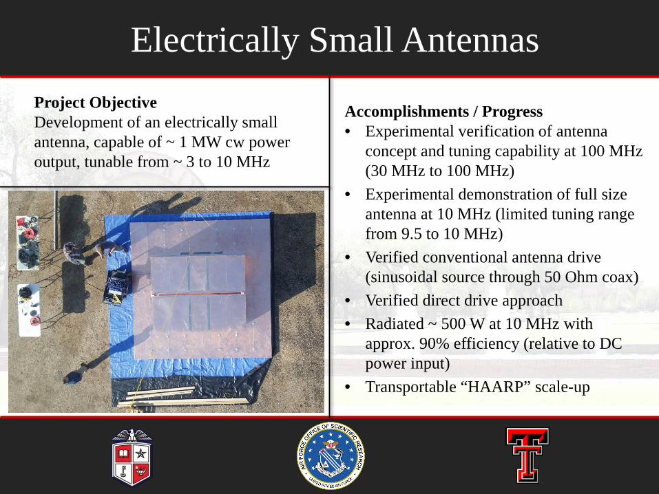
• An electrically small, inductively coupled antenna design k·a < 0.5
• Highly resonant structure Provides natural match to 50
Ohm source • Up to 98% efficient • Small Loop Antenna (SLA)
inductively couples to Capacitively Loaded Loop (CLL)
2
Stub length
Stub Space
SLA Radius
Wire Diameter
Width
Height
Dielectric
GHz range antenna (no tuning): A. Erentok and R. W. Ziolkowski, “An efficient metamaterial-inspired electrically-small antenna,” Microw. Opt. Tech. Lett, vol. 49, no. 6, pp. 1287–1290, 2007
Dielectric insertion for tuning or gap width tuning
2/10/2016
COLLABORATIVE RESEARCH ON NOVEL HIGH POWER SOURCES FOR AND PHYSICS OF IONOSPHERIC MODIFICATION
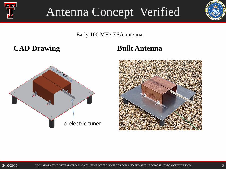
Antenna Concept Verified
CAD Drawing Built Antenna
Early 100 MHz ESA antenna
dielectric tuner
3 2/10/2016
COLLABORATIVE RESEARCH ON NOVEL HIGH POWER SOURCES FOR AND PHYSICS OF IONOSPHERIC MODIFICATION
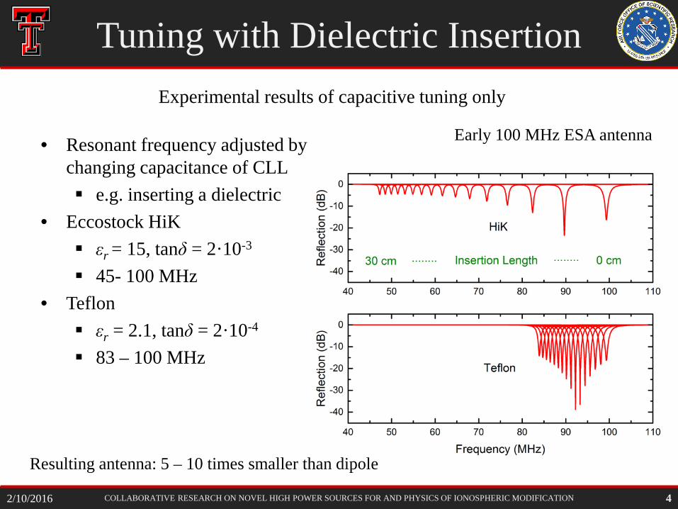
Tuning with Dielectric Insertion
• Resonant frequency adjusted by changing capacitance of CLL e.g. inserting a dielectric
• Eccostock HiK εr = 15, tanδ = 2·10-3
45- 100 MHz • Teflon
εr = 2.1, tanδ = 2·10-4
83 – 100 MHz
4
Experimental results of capacitive tuning only
Resulting antenna: 5 – 10 times smaller than dipole
Early 100 MHz ESA antenna
2/10/2016
COLLABORATIVE RESEARCH ON NOVEL HIGH POWER SOURCES FOR AND PHYSICS OF IONOSPHERIC MODIFICATION 5
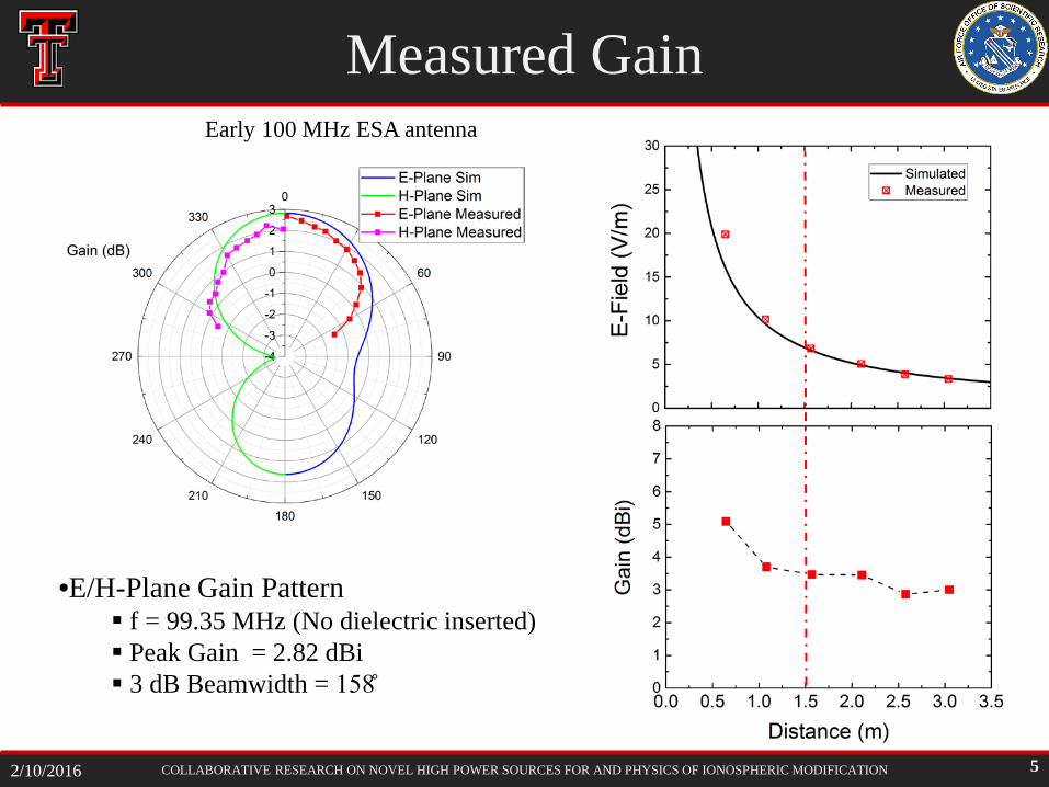
•E/H-Plane Gain Pattern f = 99.35 MHz (No dielectric inserted) Peak Gain = 2.82 dBi 3 dB Beamwidth = 158
Measured Gain Early 100 MHz ESA antenna
2/10/2016
COLLABORATIVE RESEARCH ON NOVEL HIGH POWER SOURCES FOR AND PHYSICS OF IONOSPHERIC MODIFICATION
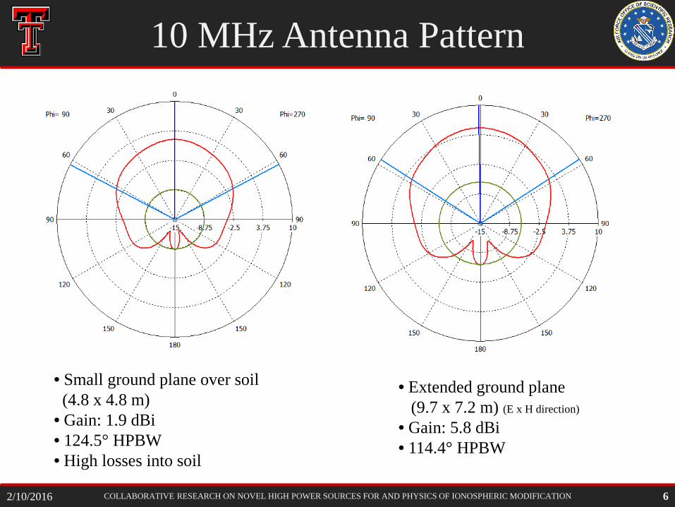
10 MHz Antenna Pattern
6
• Small ground plane over soil (4.8 x 4.8 m) • Gain: 1.9 dBi • 124.5° HPBW • High losses into soil
• Extended ground plane (9.7 x 7.2 m) (E x H direction)
• Gain: 5.8 dBi • 114.4° HPBW
2/10/2016
COLLABORATIVE RESEARCH ON NOVEL HIGH POWER SOURCES FOR AND PHYSICS OF IONOSPHERIC MODIFICATION
Horizontal Gap
• University of Maryland suggested modification
• Larger gap possible due to increased capacitive area
• Tunable by adjusting area of overlap – air tuning possible
• Increased dielectric requirement for breakdown mitigation (large volume, high quality dielectric needed)
7 2/10/2016
COLLABORATIVE RESEARCH ON NOVEL HIGH POWER SOURCES FOR AND PHYSICS OF IONOSPHERIC MODIFICATION
Horizontal Gap With Rollers
Horizontal Gap
8 2/10/2016
COLLABORATIVE RESEARCH ON NOVEL HIGH POWER SOURCES FOR AND PHYSICS OF IONOSPHERIC MODIFICATION
• tanδ = 0.0065, μ = 50, 2 cm slabs – 85.6% radiation efficiency – 13.9% loss into ferrite – 81% Accepted Power – 69% Total efficiency
Slab thickness exaggerated for visibility
Low matching quality is observed
Ferrite Tuning
9 2/10/2016
COLLABORATIVE RESEARCH ON NOVEL HIGH POWER SOURCES FOR AND PHYSICS OF IONOSPHERIC MODIFICATION
Horizontal Gap Max Power (10 MHz)
• Limited by – Air Breakdown
• > 30 kV/cm at 50 MW • Assumes adequate insulation at feed point.
– Teflon* Melting (2 MW input power) • Loss tangent: 2*10-4, 68.4 min at 9.4% loss (188 kW) • Loss tangent: 2*10-3, 18.8 min at 34.2% loss (684 kW)
– Loss of original properties • Ferrites
– Permeability changes with temperature, dependent on individual composition of soft ferrites (NiZn)
– Typical loss at 2 MW excitation: 278 kW (2 cm thick slabs)
* Teflon sheet: 15 cm thick, 200 x 300 cm approx.
10
1 to 2 MW should be feasible, air tuning preferred (6 kV/cm)
2/10/2016
COLLABORATIVE RESEARCH ON NOVEL HIGH POWER SOURCES FOR AND PHYSICS OF IONOSPHERIC MODIFICATION
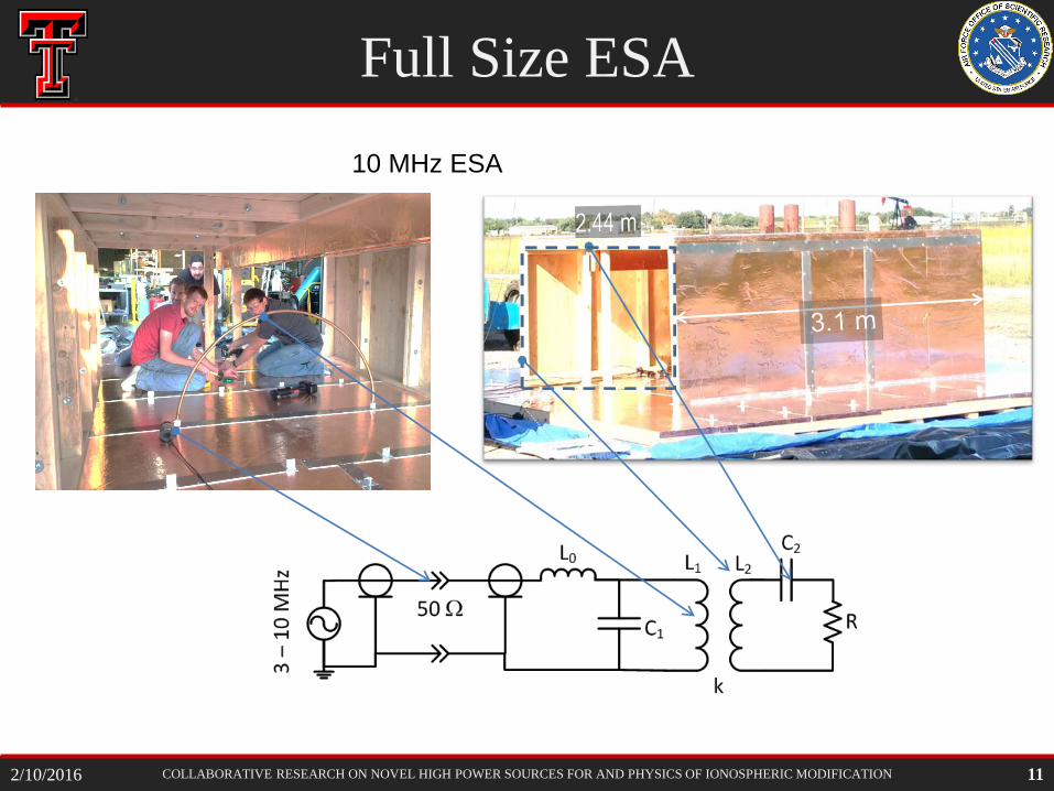
Full Size ESA
11
10 MHz ESA
2/10/2016
COLLABORATIVE RESEARCH ON NOVEL HIGH POWER SOURCES FOR AND PHYSICS OF IONOSPHERIC MODIFICATION
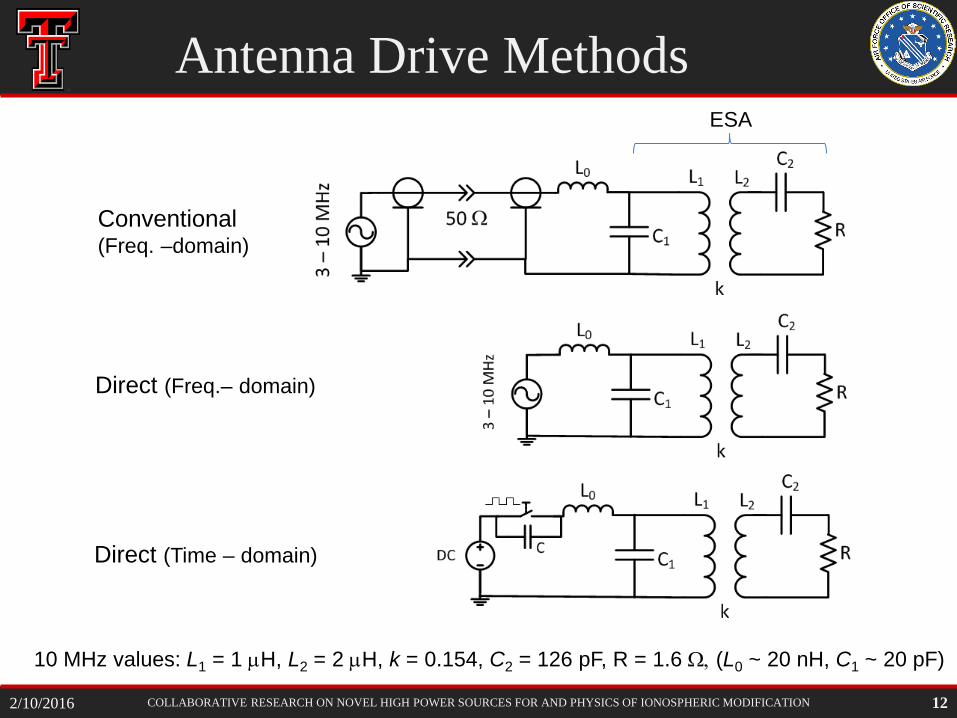
Antenna Drive Methods
Direct (Freq.– domain)
Conventional (Freq. –domain)
Direct (Time – domain)
ESA
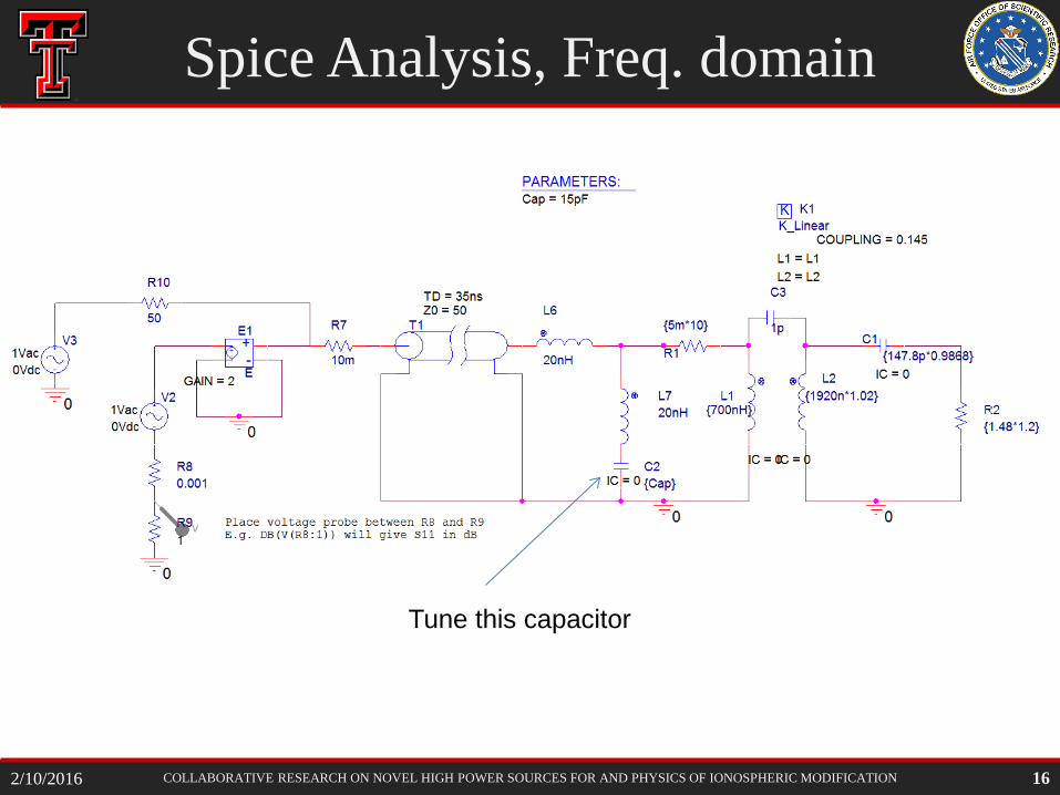
10 MHz values: L1 = 1 µH, L2 = 2 µH, k = 0.154, C2 = 126 pF, R = 1.6 Ω, (L0 ~ 20 nH, C1 ~ 20 pF)
12 2/10/2016
COLLABORATIVE RESEARCH ON NOVEL HIGH POWER SOURCES FOR AND PHYSICS OF IONOSPHERIC MODIFICATION
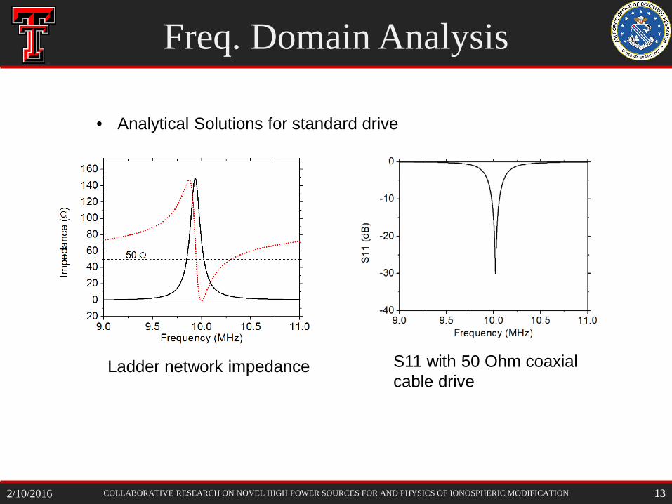
Freq. Domain Analysis
• Analytical Solutions for standard drive
Ladder network impedance S11 with 50 Ohm coaxial cable drive
13 2/10/2016
COLLABORATIVE RESEARCH ON NOVEL HIGH POWER SOURCES FOR AND PHYSICS OF IONOSPHERIC MODIFICATION
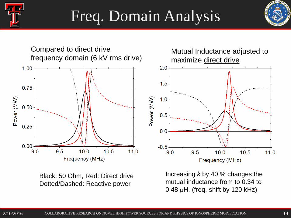
Freq. Domain Analysis
Compared to direct drive frequency domain (6 kV rms drive)
Mutual Inductance adjusted to maximize direct drive performance
Black: 50 Ohm, Red: Direct drive Dotted/Dashed: Reactive power
Increasing k by 40 % changes the mutual inductance from to 0.34 to 0.48 µH. (freq. shift by 120 kHz)
14 2/10/2016
COLLABORATIVE RESEARCH ON NOVEL HIGH POWER SOURCES FOR AND PHYSICS OF IONOSPHERIC MODIFICATION
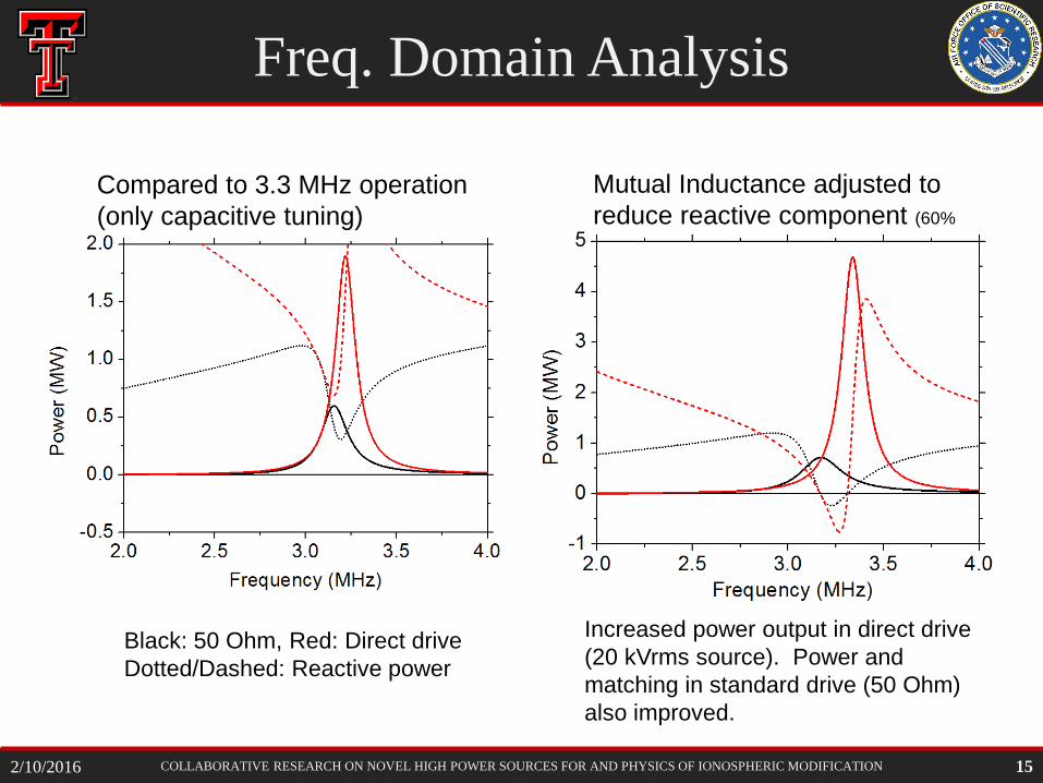
Freq. Domain Analysis
Compared to 3.3 MHz operation (only capacitive tuning)
Mutual Inductance adjusted to reduce reactive component (60% increase)
Black: 50 Ohm, Red: Direct drive Dotted/Dashed: Reactive power
Increased power output in direct drive (20 kVrms source). Power and matching in standard drive (50 Ohm) also improved.
15 2/10/2016
COLLABORATIVE RESEARCH ON NOVEL HIGH POWER SOURCES FOR AND PHYSICS OF IONOSPHERIC MODIFICATION
Spice Analysis, Freq. domain
Tune this capacitor
16 2/10/2016
COLLABORATIVE RESEARCH ON NOVEL HIGH POWER SOURCES FOR AND PHYSICS OF IONOSPHERIC MODIFICATION
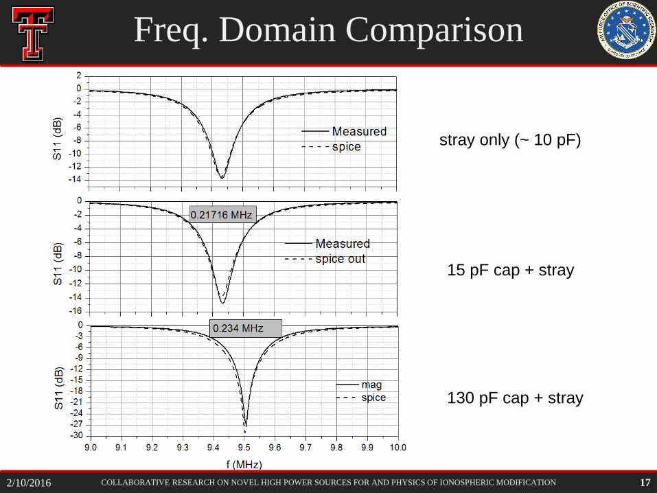
15 pF cap + stray
stray only (~ 10 pF)
130 pF cap + stray
Freq. Domain Comparison
17 2/10/2016
COLLABORATIVE RESEARCH ON NOVEL HIGH POWER SOURCES FOR AND PHYSICS OF IONOSPHERIC MODIFICATION
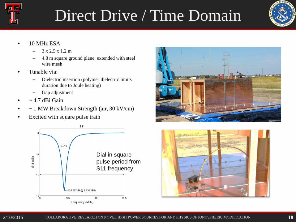
Direct Drive / Time Domain • 10 MHz ESA
– 3 x 2.5 x 1.2 m – 4.8 m square ground plane, extended with steel
wire mesh • Tunable via:
– Dielectric insertion (polymer dielectric limits duration due to Joule heating)
– Gap adjustment • ~ 4.7 dBi Gain • ~ 1 MW Breakdown Strength (air, 30 kV/cm) • Excited with square pulse train
Dial in square pulse period from S11 frequency
18 2/10/2016
COLLABORATIVE RESEARCH ON NOVEL HIGH POWER SOURCES FOR AND PHYSICS OF IONOSPHERIC MODIFICATION
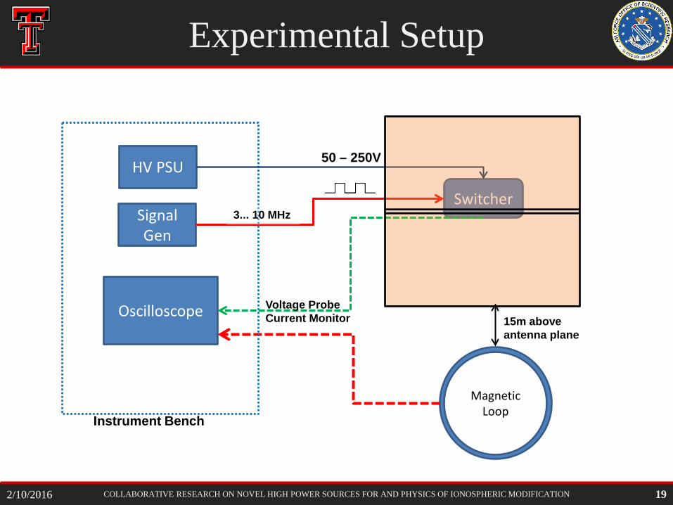
Experimental Setup
Switcher
Oscilloscope
Magnetic Loop
Signal Gen
Instrument Bench
HV PSU
Voltage Probe Current Monitor
50 – 250V
3... 10 MHz
15m above antenna plane
19 2/10/2016
COLLABORATIVE RESEARCH ON NOVEL HIGH POWER SOURCES FOR AND PHYSICS OF IONOSPHERIC MODIFICATION
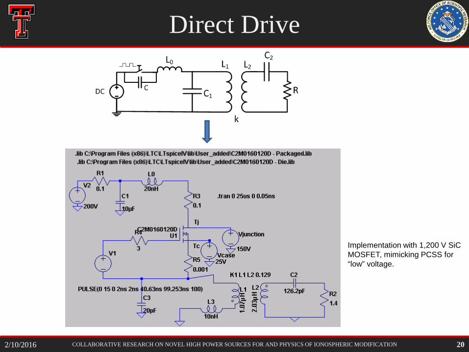
Direct Drive
20
Implementation with 1,200 V SiC MOSFET, mimicking PCSS for “low” voltage.
2/10/2016
COLLABORATIVE RESEARCH ON NOVEL HIGH POWER SOURCES FOR AND PHYSICS OF IONOSPHERIC MODIFICATION
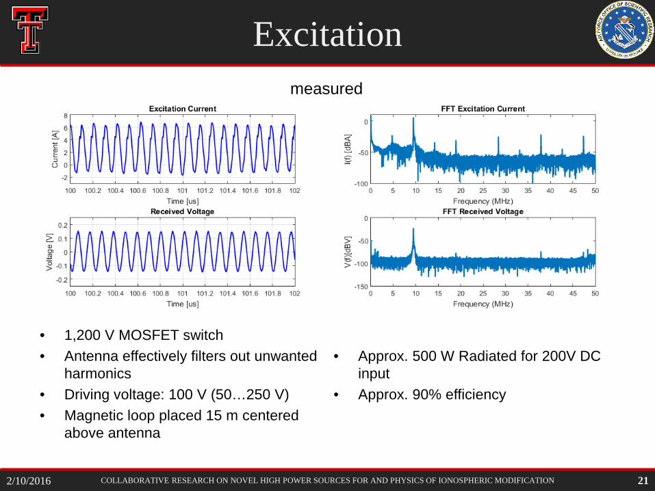
Excitation
• 1,200 V MOSFET switch • Antenna effectively filters out unwanted
harmonics • Driving voltage: 100 V (50…250 V) • Magnetic loop placed 15 m centered
above antenna
• Approx. 500 W Radiated for 200V DC
input • Approx. 90% efficiency
21
measured
2/10/2016
COLLABORATIVE RESEARCH ON NOVEL HIGH POWER SOURCES FOR AND PHYSICS OF IONOSPHERIC MODIFICATION
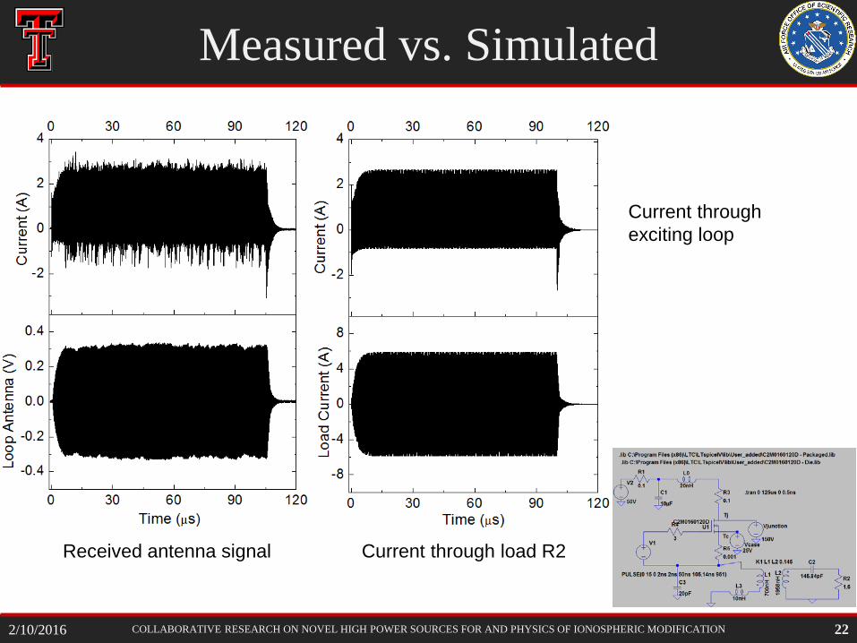
Measured vs. Simulated
22
Current through exciting loop
Received antenna signal Current through load R2
2/10/2016
COLLABORATIVE RESEARCH ON NOVEL HIGH POWER SOURCES FOR AND PHYSICS OF IONOSPHERIC MODIFICATION
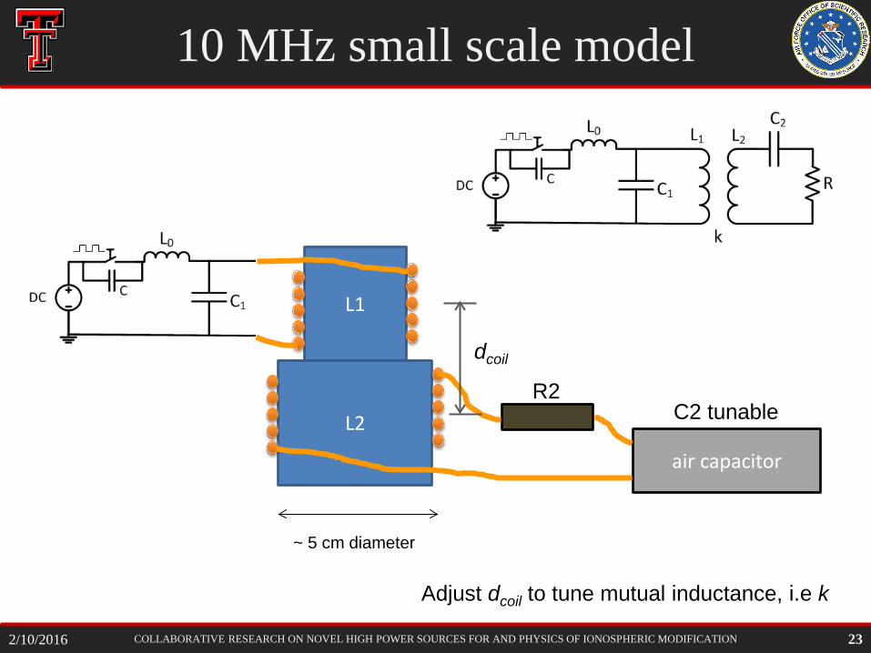
10 MHz small scale model
23
L1
L2 R2
air capacitor
C2 tunable
~ 5 cm diameter
dcoil
Adjust dcoil to tune mutual inductance, i.e k
2/10/2016
COLLABORATIVE RESEARCH ON NOVEL HIGH POWER SOURCES FOR AND PHYSICS OF IONOSPHERIC MODIFICATION
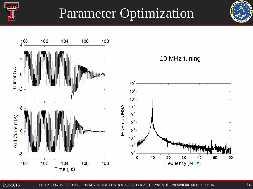
Parameter Optimization
24
10 MHz tuning
2/10/2016
COLLABORATIVE RESEARCH ON NOVEL HIGH POWER SOURCES FOR AND PHYSICS OF IONOSPHERIC MODIFICATION
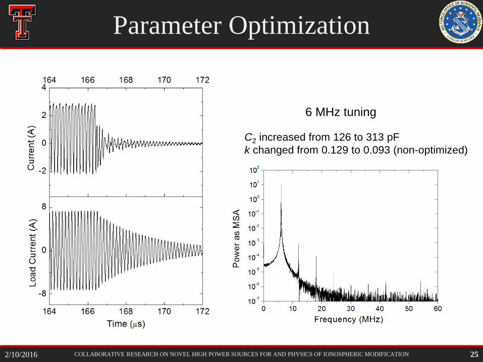
Parameter Optimization
25
6 MHz tuning
C2 increased from 126 to 313 pF k changed from 0.129 to 0.093 (non-optimized)
2/10/2016
COLLABORATIVE RESEARCH ON NOVEL HIGH POWER SOURCES FOR AND PHYSICS OF IONOSPHERIC MODIFICATION
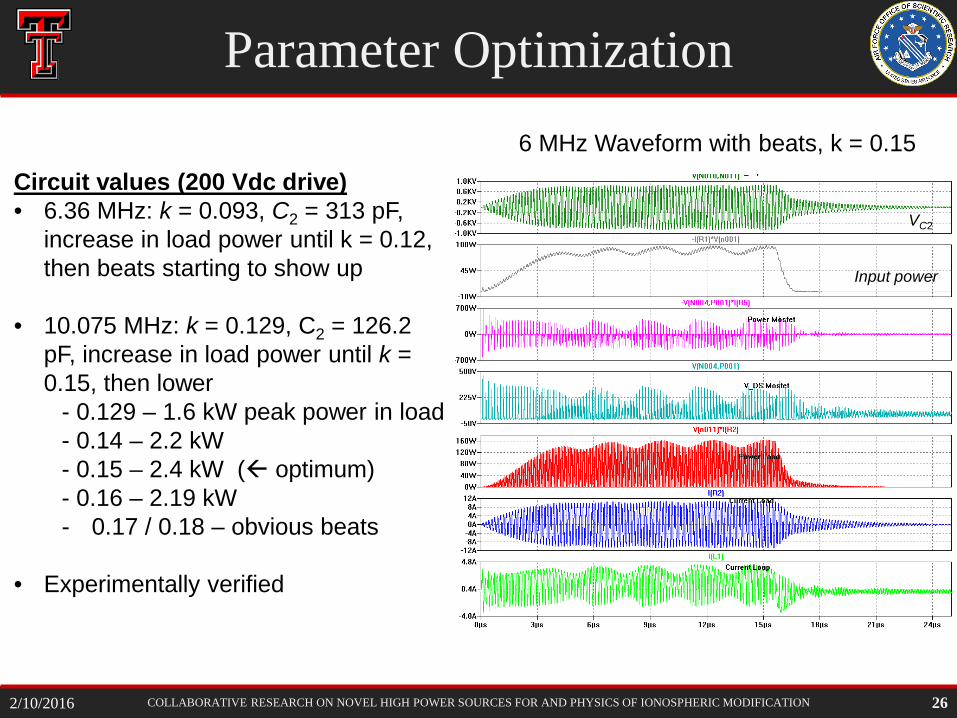
Parameter Optimization
26
Circuit values (200 Vdc drive) • 6.36 MHz: k = 0.093, C2 = 313 pF,
increase in load power until k = 0.12, then beats starting to show up
• 10.075 MHz: k = 0.129, C2 = 126.2
pF, increase in load power until k = 0.15, then lower
- 0.129 – 1.6 kW peak power in load - 0.14 – 2.2 kW - 0.15 – 2.4 kW ( optimum) - 0.16 – 2.19 kW - 0.17 / 0.18 – obvious beats
• Experimentally verified
6 MHz Waveform with beats, k = 0.15
VC2
Input power
2/10/2016
COLLABORATIVE RESEARCH ON NOVEL HIGH POWER SOURCES FOR AND PHYSICS OF IONOSPHERIC MODIFICATION
Parameter Optimization
27
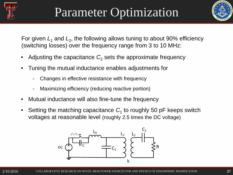
For given L1 and L2, the following allows tuning to about 90% efficiency (switching losses) over the frequency range from 3 to 10 MHz:
• Adjusting the capacitance C2 sets the approximate frequency
• Tuning the mutual inductance enables adjustments for
- Changes in effective resistance with frequency
- Maximizing efficiency (reducing reactive portion)
• Mutual inductance will also fine-tune the frequency
• Setting the matching capacitance C1 to roughly 50 pF keeps switch voltages at reasonable level (roughly 2.5 times the DC voltage)
2/10/2016
COLLABORATIVE RESEARCH ON NOVEL HIGH POWER SOURCES FOR AND PHYSICS OF IONOSPHERIC MODIFICATION
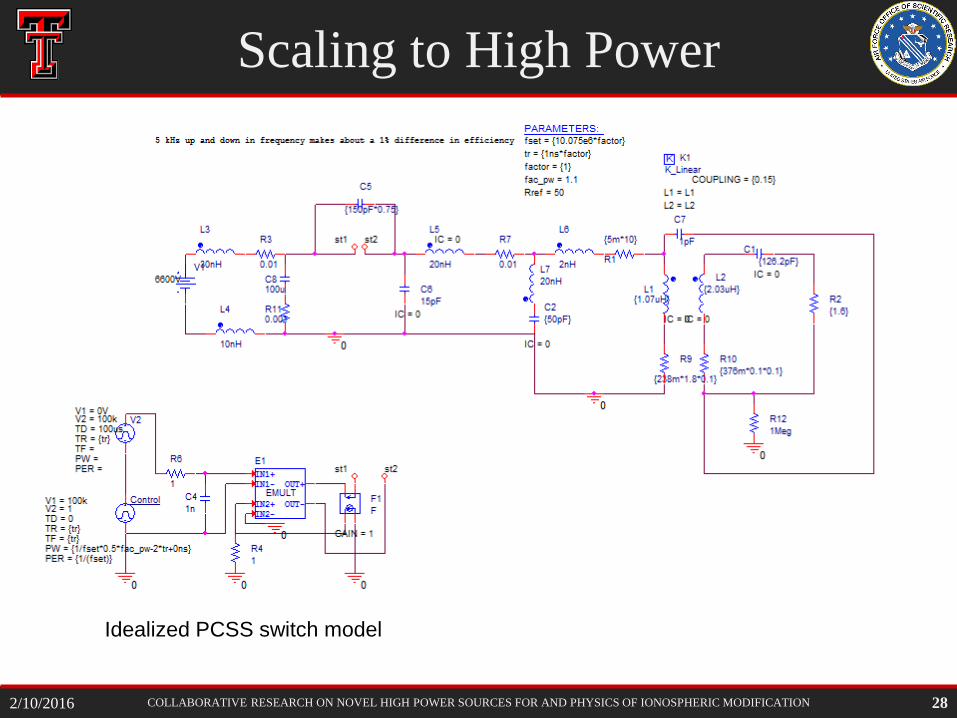
Scaling to High Power
28 2/10/2016
Idealized PCSS switch model
COLLABORATIVE RESEARCH ON NOVEL HIGH POWER SOURCES FOR AND PHYSICS OF IONOSPHERIC MODIFICATION
System Scaling
29
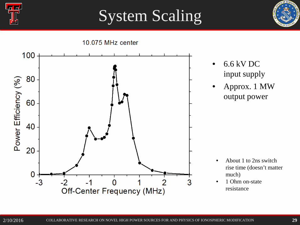
• About 1 to 2ns switch rise time (doesn’t matter much)
• 1 Ohm on-state resistance
• 6.6 kV DC input supply
• Approx. 1 MW output power
2/10/2016
COLLABORATIVE RESEARCH ON NOVEL HIGH POWER SOURCES FOR AND PHYSICS OF IONOSPHERIC MODIFICATION
System Scaling
30
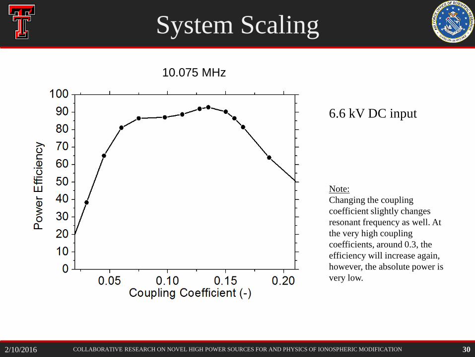
6.6 kV DC input
Note: Changing the coupling coefficient slightly changes resonant frequency as well. At the very high coupling coefficients, around 0.3, the efficiency will increase again, however, the absolute power is very low.
10.075 MHz
2/10/2016
COLLABORATIVE RESEARCH ON NOVEL HIGH POWER SOURCES FOR AND PHYSICS OF IONOSPHERIC MODIFICATION
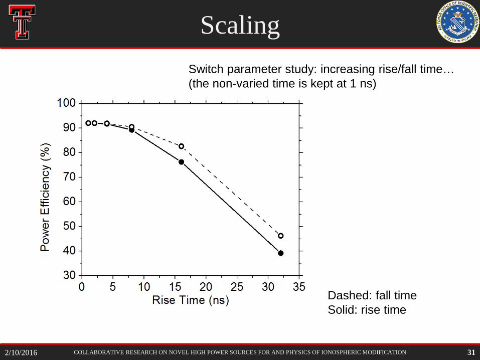
Scaling
31
Dashed: fall time Solid: rise time
Switch parameter study: increasing rise/fall time… (the non-varied time is kept at 1 ns)
2/10/2016
COLLABORATIVE RESEARCH ON NOVEL HIGH POWER SOURCES FOR AND PHYSICS OF IONOSPHERIC MODIFICATION
Physical Implementation
32
Requirements: • Adjust capacitance from 100 pF to about 1.3 nF for full 2 to 10 MHz range • Adjust mutual inductance, coupling coefficient from 0.15 to 0.09 • Handle 1 MW power, support fields up to 20 kV/cm
Challenges: • Capacitance adjustment technique with low loss
- Air gap tuning - Dielectric tuning - Magnetic tuning
• Adjusting mutual inductance will affect the driving loop inductance - Take coupling between L1 and k into account for tuning
2/10/2016
COLLABORATIVE RESEARCH ON NOVEL HIGH POWER SOURCES FOR AND PHYSICS OF IONOSPHERIC MODIFICATION
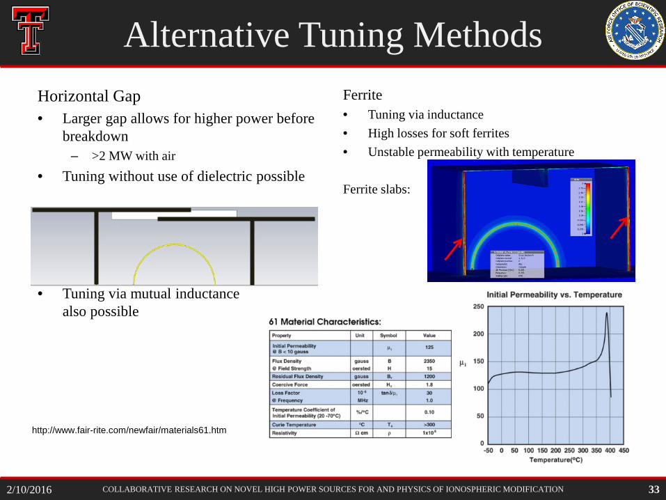
Alternative Tuning Methods Horizontal Gap • Larger gap allows for higher power before
breakdown – >2 MW with air
• Tuning without use of dielectric possible
• Tuning via mutual inductance also possible
Ferrite • Tuning via inductance • High losses for soft ferrites • Unstable permeability with temperature
Ferrite slabs:
http://www.fair-rite.com/newfair/materials61.htm
33 2/10/2016
COLLABORATIVE RESEARCH ON NOVEL HIGH POWER SOURCES FOR AND PHYSICS OF IONOSPHERIC MODIFICATION
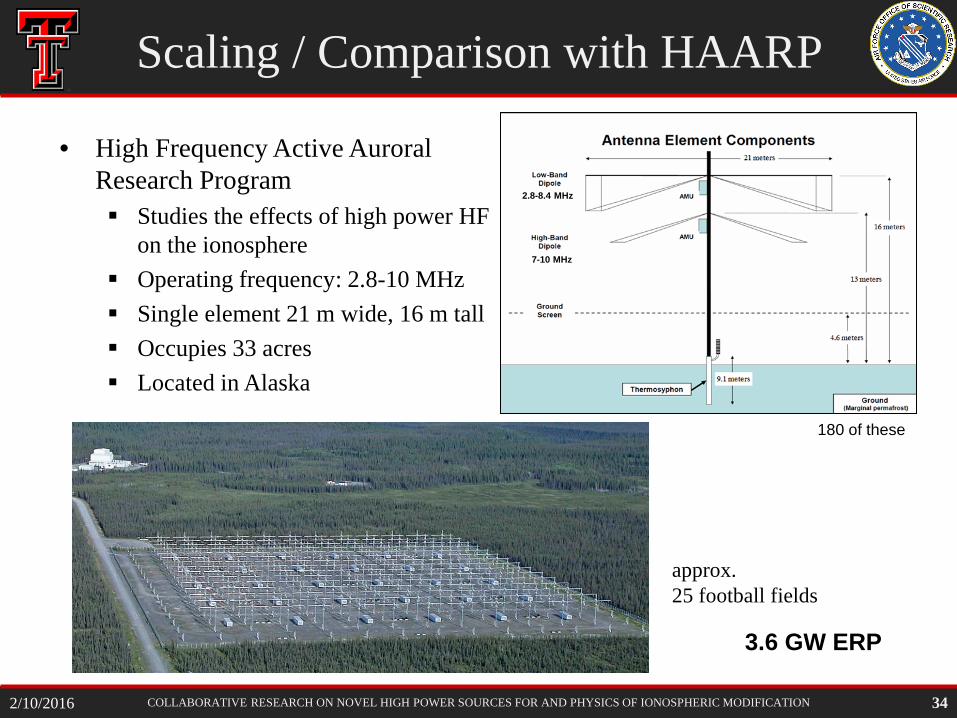
• High Frequency Active Auroral Research Program Studies the effects of high power HF
on the ionosphere Operating frequency: 2.8-10 MHz Single element 21 m wide, 16 m tall Occupies 33 acres Located in Alaska
7-10 MHz
2.8-8.4 MHz
Scaling / Comparison with HAARP
approx. 25 football fields
180 of these
3.6 GW ERP
34 2/10/2016
COLLABORATIVE RESEARCH ON NOVEL HIGH POWER SOURCES FOR AND PHYSICS OF IONOSPHERIC MODIFICATION
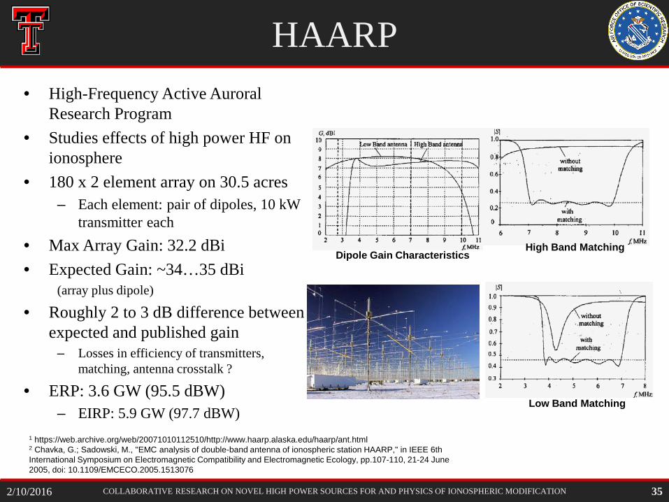
HAARP • High-Frequency Active Auroral
Research Program • Studies effects of high power HF on
ionosphere • 180 x 2 element array on 30.5 acres
– Each element: pair of dipoles, 10 kW transmitter each
• Max Array Gain: 32.2 dBi • Expected Gain: ~34…35 dBi
(array plus dipole)
• Roughly 2 to 3 dB difference between expected and published gain
– Losses in efficiency of transmitters, matching, antenna crosstalk ?
• ERP: 3.6 GW (95.5 dBW) – EIRP: 5.9 GW (97.7 dBW)
1 https://web.archive.org/web/20071010112510/http://www.haarp.alaska.edu/haarp/ant.html 2 Chavka, G.; Sadowski, M., "EMC analysis of double-band antenna of ionospheric station HAARP," in IEEE 6th International Symposium on Electromagnetic Compatibility and Electromagnetic Ecology, pp.107-110, 21-24 June 2005, doi: 10.1109/EMCECO.2005.1513076
High Band Matching
Low Band Matching
Dipole Gain Characteristics
35 2/10/2016
COLLABORATIVE RESEARCH ON NOVEL HIGH POWER SOURCES FOR AND PHYSICS OF IONOSPHERIC MODIFICATION
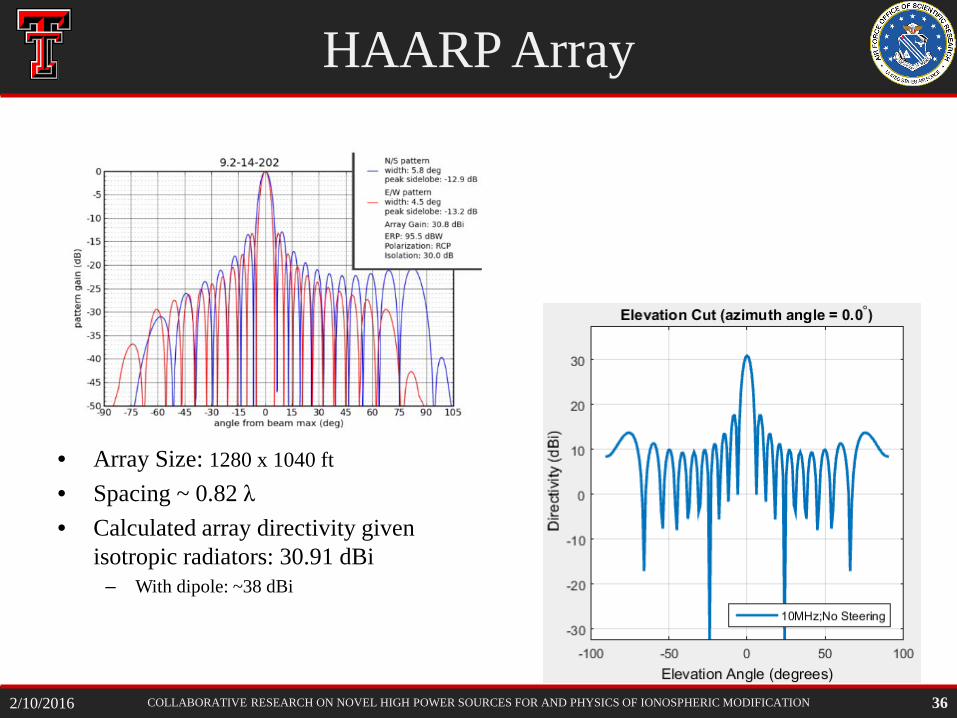
HAARP Array
• Array Size: 1280 x 1040 ft • Spacing ~ 0.82 λ • Calculated array directivity given
isotropic radiators: 30.91 dBi – With dipole: ~38 dBi
36 2/10/2016
COLLABORATIVE RESEARCH ON NOVEL HIGH POWER SOURCES FOR AND PHYSICS OF IONOSPHERIC MODIFICATION
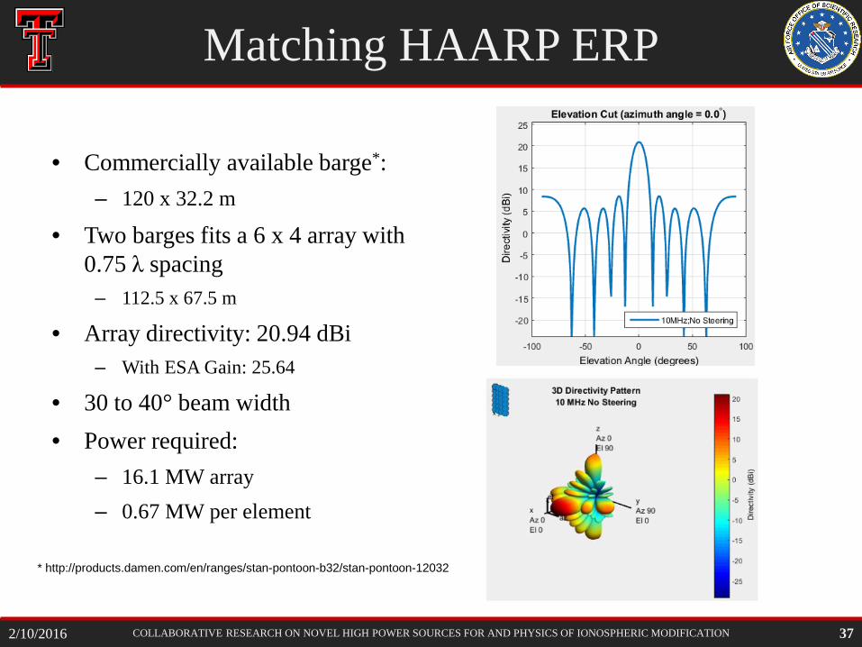
Matching HAARP ERP
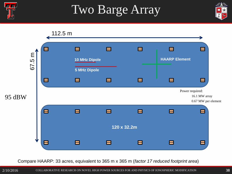
• Commercially available barge*: – 120 x 32.2 m
• Two barges fits a 6 x 4 array with 0.75 λ spacing
– 112.5 x 67.5 m
• Array directivity: 20.94 dBi – With ESA Gain: 25.64
• 30 to 40° beam width • Power required:
– 16.1 MW array – 0.67 MW per element
* http://products.damen.com/en/ranges/stan-pontoon-b32/stan-pontoon-12032
37 2/10/2016
COLLABORATIVE RESEARCH ON NOVEL HIGH POWER SOURCES FOR AND PHYSICS OF IONOSPHERIC MODIFICATION
10 MHz Dipole
5 MHz Dipole
HAARP Element
112.5 m 67
.5 m
120 x 32.2m
Two Barge Array
Compare HAARP: 33 acres, equivalent to 365 m x 365 m (factor 17 reduced footprint area)
38
Power required: 16.1 MW array 0.67 MW per element
95 dBW
2/10/2016
COLLABORATIVE RESEARCH ON NOVEL HIGH POWER SOURCES FOR AND PHYSICS OF IONOSPHERIC MODIFICATION
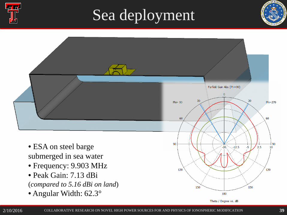
Sea deployment
39
• ESA on steel barge submerged in sea water • Frequency: 9.903 MHz • Peak Gain: 7.13 dBi (compared to 5.16 dBi on land) • Angular Width: 62.3°
2/10/2016
COLLABORATIVE RESEARCH ON NOVEL HIGH POWER SOURCES FOR AND PHYSICS OF IONOSPHERIC MODIFICATION
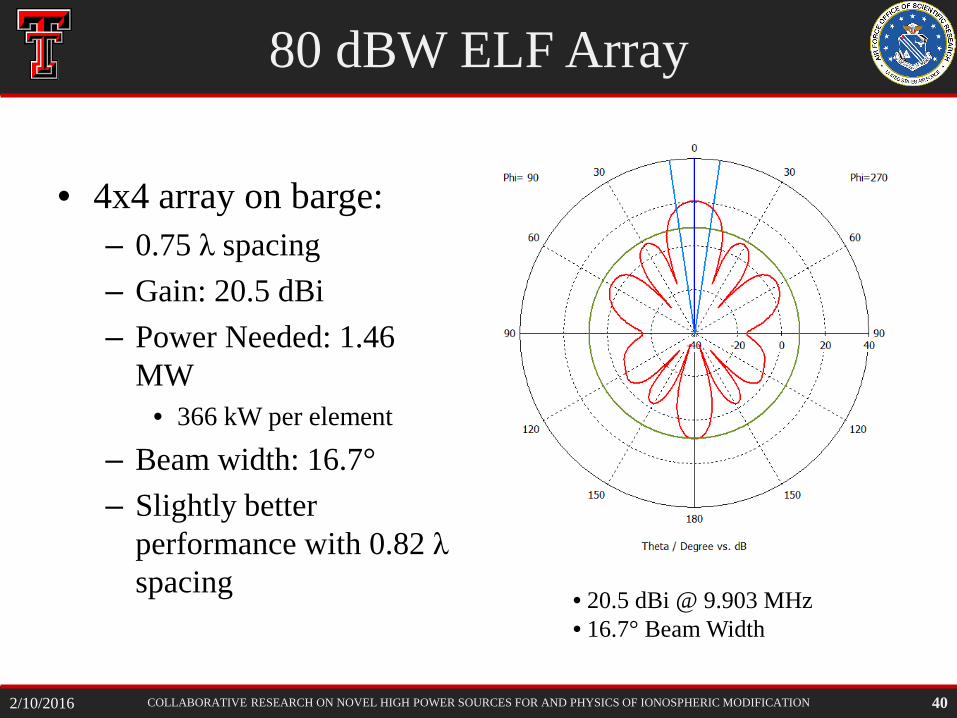
80 dBW ELF Array
• 4x4 array on barge: – 0.75 λ spacing – Gain: 20.5 dBi – Power Needed: 1.46
MW • 366 kW per element
– Beam width: 16.7° – Slightly better
performance with 0.82 λ spacing
40
• 20.5 dBi @ 9.903 MHz • 16.7° Beam Width
2/10/2016
COLLABORATIVE RESEARCH ON NOVEL HIGH POWER SOURCES FOR AND PHYSICS OF IONOSPHERIC MODIFICATION 41
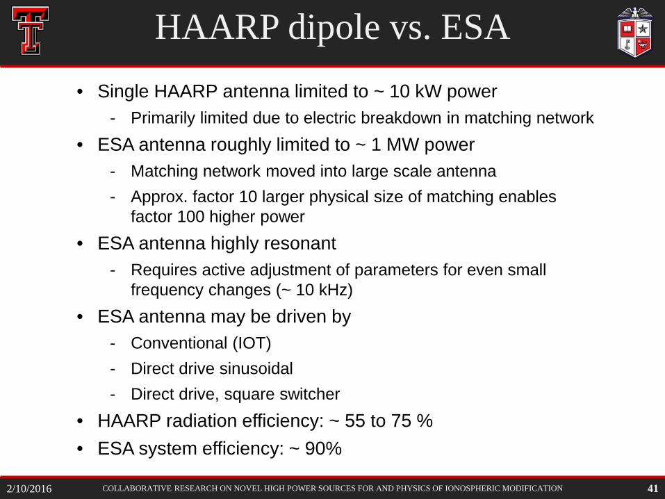
HAARP dipole vs. ESA • Single HAARP antenna limited to ~ 10 kW power
- Primarily limited due to electric breakdown in matching network • ESA antenna roughly limited to ~ 1 MW power
- Matching network moved into large scale antenna - Approx. factor 10 larger physical size of matching enables
factor 100 higher power • ESA antenna highly resonant
- Requires active adjustment of parameters for even small frequency changes (~ 10 kHz)
• ESA antenna may be driven by - Conventional (IOT) - Direct drive sinusoidal - Direct drive, square switcher
• HAARP radiation efficiency: ~ 55 to 75 % • ESA system efficiency: ~ 90%
2/10/2016
COLLABORATIVE RESEARCH ON NOVEL HIGH POWER SOURCES FOR AND PHYSICS OF IONOSPHERIC MODIFICATION
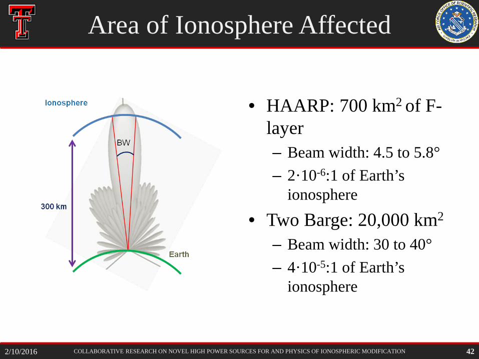
Area of Ionosphere Affected
• HAARP: 700 km2 of F-layer – Beam width: 4.5 to 5.8° – 2·10-6:1 of Earth’s
ionosphere • Two Barge: 20,000 km2
– Beam width: 30 to 40° – 4·10-5:1 of Earth’s
ionosphere
42 2/10/2016
COLLABORATIVE RESEARCH ON NOVEL HIGH POWER SOURCES FOR AND PHYSICS OF IONOSPHERIC MODIFICATION
Future Plans
• Verify tuning methods that worked in 3 to 10 MHz mockup with full-size antenna
• Verify matching approach with full size antenna
• Develop practical mutual inductance tuning
• Find optimum capacitive gap geometry
• Evaluate array performance at shorter spacing (antenna cross-talk)
• Drive antenna mockup with PCSS
• Evaluate antenna geometry for 10 MHz breakdown limits (several MW cw)
• Drive antenna with IOT or similar mock source
43 2/10/2016
Recommended


![Electrically Small Antenna Design - ITS Small Antenna Design ... Example : microstrip patch antenna Ground plane ... Bandwidth [MHz] relative patch size f r =1 GHz](https://img.pdfslide.net/doc/110x75/5aa70bfa7f8b9a6d5a8bcb7d/electrically-small-antenna-design-its-small-antenna-design-example-microstrip.jpg)