1
archived as http://www.stealthskater.com/Documents/ECM_02.pdf
more related articles at http://www.stealthskater.com/Military.htm
note: because important websites are frequently "here today but gone tomorrow", the following was
archived from http://ourworld.compuserve.com/homepages/edperry/ewtutor1.htm#Sec1 on
01/28/2008. This is NOT an attempt to divert readers from the aforementioned website.
Indeed, the reader should only read this back-up copy if the updated original cannot be found
at the original author's site.
Electronics Counter-Measures (ECM) Tutorial
1.0 . . . . . . INTRODUCTION
2.0 . . . . . . RADAR PRINCIPLES
2.1 . . . . . . Target Tracking Radars (TTR)
2.1.1 . . . . .Range
2.1.1.1 . . . Range Tracking
2.1.1.2 . . . Range Jamming
2.1.2 . . . . .Angle
2.1.2.1 . . . Beamwidth
2.1.2.2 . . . Polarization
2.1.2.3 . . . Angle Tracking
2.1.2.4 . . . Angle Jamming
2.1.2.5 . . . TTR Summary
2.2 . . . . . . Radar Parameters Used in RWR
2.2.1 . . . . .Frequency
2.2.2 . . . . .Pulsewidth
2.2.3 . . . . .Pulse Repetition Frequency
2.2.3.1 . . . Stagger
2.2.3.2 . . . Jitter
2.2.3.3 . . . Stagger-Jitter Patterns
2.2.4 . . . . .Missile Guidance
2.2.4.1 . . . Command Guidance
2.2.4.2 . . . Homing Guidance
2.2.4.3 . . . Beam Rider Guidance
2.2.4.4 . . . Fuse Jamming
2.2.4.5 . . . Missile Guidance Correlation
2.2.5 . . . . .Scan
2.2.5.1 . . . Conical Scan
2.2.5.2 . . . Track-While-Scan
2.2.5.3 . . . Monopulse Scan
2.2.5.4 . . . Received Scan Patterns
2.2.5.5 . . . Scan Summary
2.3 . . . . . . Electronic Counter-Countermeasures
2.3.1 . . . . .Optical Tracking
2.3.2 . . . . .Automatic Gain Control
2
2.3.3 . . . . .Instantaneous Automatic Gain Control
2.3.4 . . . . .Moving Target Indicator
2.3.5 . . . . .Lobe on Receive Only (LORO)
2.3.6 . . . . .Fast Time Constant
2.4 . . . . . . Types of Radars
2.4.1 . . . . .Pulse Radars
2.4.2 . . . . .CW Radars
2.4.3 . . . . .Radars Other Than SAM Fire Control
2.4.3.1 . . . Early Warning Radars
2.4.3.2 . . . Acquisition Radars
2.4.3.3 . . . Height Finder Radars
2.4.3.4 . . . Ground-Controlled Intercept Radars
2.4.3.5 . . . Ground-Controlled Approach Radars
2.4.3.6 . . . Anti-Aircraft Artillery Radars
2.4.3.7 . . . Airborne Interceptor Radars
2.4.3.8 . . . Terminal Defense Radars
3.0 . . . . . . RADAR WARNING RECEIVER SYSTEMS
4.0 . . . . . . COCKPITOLOGY
5.0 . . . . . . GLOSSARY OF ELECTRONIC WARFARE TERMS
1.0 INTRODUCTION
This area of the site provides a tutorial which is intended to provide fundamental definitions and
descriptions of the various principles of radar systems with emphasis on target acquisition and tracking
plus weapon guidance systems.
A proper understanding of these principles is necessary in order to derive an appreciation for the
operational use of Defensive Electronic Countermeasures (DECM) and digital Threat Warning Systems
(TWS).
The tutorial concludes with a brief section on the generic system concept of digital Radar Warning
Receiver Systems (RWR) with reference to certain specific systems on which more information can be
provided in an advanced course on Passive EW.
Finally, an extensive glossary of Electronic Warfare terms provides a handy reference to these
frequently used definitions.
2.0 RADAR PRINCIPLES
Radar ("Radio Detection and Ranging") is employed in many forms from complex air defense
networks to simple IFF beacons and altimeters. The primary threat radars for aircraft are the fire control
radars associated with weapons (particularly guided missiles). In this section, each radar and radar
parameter important to RWR will be discussed in a general manner. Frequent reference will be made to
more detailed sources; the reader should pursue these sources in the library.
3
2.1 Target Tracking Radars (TTR)
Before one can understand electronic warfare, one must first know the principles of radar tracking.
The emphasis in this tutorial will be placed on pulsed radars since they are the most commonly used.
(Continuous wave (CW) radars are described in Section 2.4.2. Note, however, that only the techniques
change and the principles are the same.)
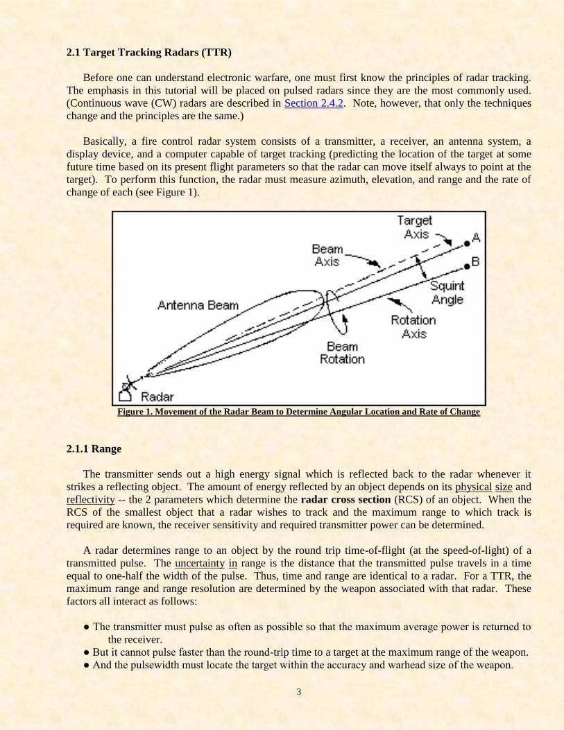
Basically, a fire control radar system consists of a transmitter, a receiver, an antenna system, a
display device, and a computer capable of target tracking (predicting the location of the target at some
future time based on its present flight parameters so that the radar can move itself always to point at the
target). To perform this function, the radar must measure azimuth, elevation, and range and the rate of
change of each (see Figure 1).
Figure 1. Movement of the Radar Beam to Determine Angular Location and Rate of Change
2.1.1 Range
The transmitter sends out a high energy signal which is reflected back to the radar whenever it
strikes a reflecting object. The amount of energy reflected by an object depends on its physical size and
reflectivity -- the 2 parameters which determine the radar cross section (RCS) of an object. When the
RCS of the smallest object that a radar wishes to track and the maximum range to which track is
required are known, the receiver sensitivity and required transmitter power can be determined.
A radar determines range to an object by the round trip time-of-flight (at the speed-of-light) of a
transmitted pulse. The uncertainty in range is the distance that the transmitted pulse travels in a time
equal to one-half the width of the pulse. Thus, time and range are identical to a radar. For a TTR, the
maximum range and range resolution are determined by the weapon associated with that radar. These
factors all interact as follows:
● The transmitter must pulse as often as possible so that the maximum average power is returned to
the receiver.
● But it cannot pulse faster than the round-trip time to a target at the maximum range of the weapon.
● And the pulsewidth must locate the target within the accuracy and warhead size of the weapon.
4
Example: The weapon has a 40 nautical mile maximum intercept range and its kill radius is 300 feet.
The pulse travels about 1000 feet per microsecond so that the time to-and-from the target is 500
microseconds. The pulse width must be 0.6 microseconds or less. Therefore, the radar cannot pulse
faster than about 2,000 times per second with a Pulse Width of 0.6 microseconds.
2.1.1.1 Range Tracking
A TTR receives initial range information from an assisting radar as will be discussed later in this
Tutorial. Receiver signal-to-noise ratio can be greatly improved by only "opening" the receiver input
circuitry when a target echo is expected. This is called "range gating" and the period when the receiver
is open is called the Range Gate. The optimum time interval for a range gate is equal to the pulsewidth
of the radar.
By using 2 adjacent range gates, the radar can determine where the target is (equal return in both
gates). As the return becomes unequal in these 2 gates, the radar can measure range rate and direction of
change. With this data, the radar computer can automatically range track a moving target. This is
known as Range Gate Tracking. Automatic range tracking is accomplished by keeping equal target
return in 2 adjacent range gates as the target moves.
(From here you may return to Table of Contents or return to Top Site Page or simply continue.)
2.1.1.2 Range Jamming
If the radar pulsed at twice the rate of the example above, a target at 40 nautical miles would reflect 2
pulses in 500 microseconds and 2 targets would appear -- one at 20 nm and one at 40 nm -- so that range
information is unreliable. This is the most common form of ECM. For each pulse of the radar, send
back one-or-more pulses from a target carried transmitter to destroy range data. If the ECM pulse
repetition rate (PRR) is properly selected, the radar will "see" and display a continuous chain of targets
along the radial from the radar to the true target and beyond.
A long line of targets generates a continuous chain of undesirable pulses in the receiver (e.g., noise).
Since time and distance are the same for a radar, these noise pulses need not be physically removed from
the target but can be generated on board. This is known as noise jamming -- sending random, high rate
false target echoes to the radar (see Figure 2). If the radar is multiple frequency (RF) or there are several
different radars in the area, noise can be generated at all frequencies by "sweeping" the frequency of the
noise pulses through all the known frequencies at a rate at least equal to or faster than the pulse rates of
the radars.
5
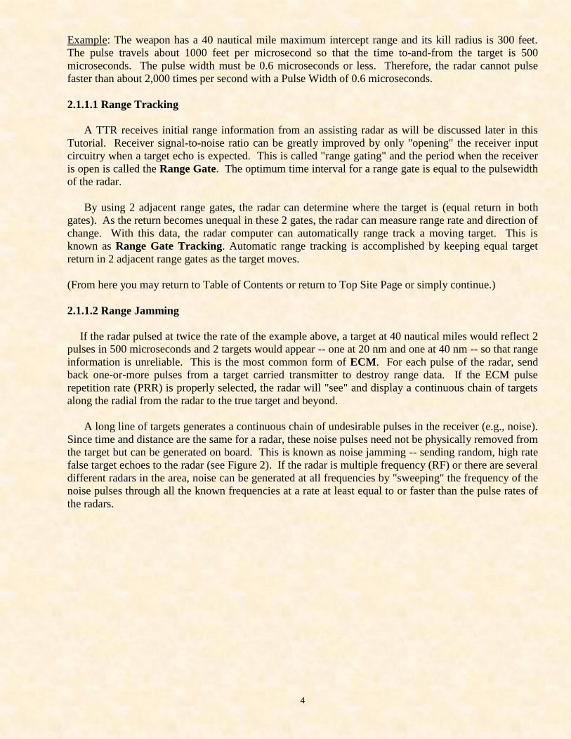
Figure 2. Example of Range Jamming
The target is generating a pulse train whose PRF is selected to provide a false target return in every
range resolution cell of the radar, thereby denying range information.
2.1.2 Angle
2.1.2.1 Beamwidth
A radar determines angle information by using an antenna array to focus the transmitted signal into a
well defined beam. Due to the property of antenna reciprocity, signals will be received from the same
area defined by the transmitted beam. (A directional transmitter is a directional receiver.) When an
antenna focuses a beam, it produces a main lobe and numerous side lobes. The more directional the
antenna, the greater the number of side lobes. In a perfect antenna, the size of the main lobe is
{(A) (w)} / s
where A is the angle (in radians), w is the transmitter wavelength, and s is a geometrical factor
determined by the physical size and shape of the antenna.
For a given frequency, the larger the antenna, the smaller the main lobe. This formula defines the
entire main lobe (beam) size whose energy distribution has a central maximum and falls to zero at the
edges. The points at which the power falls to 0.707 of the maximum are known as the half-power
points. And the angular size of the beam between these half-power points is the defined beamwidth of
the radar. This definition is always understood when discussing radar parameters. But the difference
between the full beamwidth and the defined beamwidth becomes important in EW. Outside the defined
beamwidth, the power drops very rapidly to the outer edges of the full beamwidth.
2.1.2.2 Polarization
Radar beams will also be polarized. Polarization is the physical orientation of the E and H fields
which exist in electromagnetic energy. For best efficiency, the transmitting and receiving antennae
should have the same polarization.
6
2.1.2.3 Anqle Trackinq
When a radar attempts to locate a target (i.e., scans a small sector of its total tracking envelope), the
target receives a large number of pulses, each from a slightly different orientation of the antenna. The
radar computer measures each pulse and generates a power plot in which the maximum point is called
the power centroid. The accuracy of the radar is a measure of its ability to locate the power centroid
and align its antenna so that the centroid is on the antenna axis. Automatic Angle Tracking is
accomplished by keeping the power centroid centered on the antenna axis as the target moves.
To track the centroid of power, the radar must "look" at antenna angles where there is no return
from the target (i.e., it must look where the target is not). This looking is also called scanning and can
be the same scan used for acquiring (locating) the target as in a Track-while-Scan (TWS) radar. Note
that this implies that for best tracking the beamwidth should be larger than the target so that no target
exists in adjacent beamwidths.
If the target is bigger than the beamwidth of the radar, the power return will be about equal in
several antenna orientations so that the power centroid will be broad in angle and thus degrade tracking
accuracy. If the target is much larger than the beamwidth, the power centroid will be so broad that the
radar will not be able to track but instead will "walk" over the target due to the scan while looking for
some point of higher return.
Resolution is the ability to distinguish multiple targets. When the computer generates the power
plot, any pulse whose value is less than 0.707 of the power centroid is assumed to be from a different
beamwidth due to the definition of beamwidth. Therefore, to resolve 2 targets there must be a point
between them where the returned power is down to the half-power points. But that -- by definition -- is
a separation equal to the beamwidth of the radar. The resolution cell of the radar, then, is the solid
volume described by one beamwidth and the range resolution. Multiple targets within one res cell will
appear as one target whose power centroid will be located somewhere between all the targets to the
accuracy of the radar.
Some radar systems use separate, large-beamed transmitters for Azimuth (Az) and Elevation (El)
tracking. This scheme allows the system to track one power centroid while scanning (TWS) its full
acquisition sector. The resolution for such a dual beam system is often given as the intersection of the
smallest dimension of each beam. Bt this is not to be confused with the resolution cell.
For a dual beam TWS system, each transmitter has a res cell in which the power centroid of the
target or targets will be located to within one beamwidth. The TWS computer can then locate the 2
power centroids to within the size of the intersecting area of the 2 beams. This difference between the
computed resolution (which is often the published resolution) and the resolution can be important to
ECM tactics. The 2 beams, -- due to their different physical orientations -- may receive differing
amounts of jamming. Since every radar requires three coordinates for accurate tracking -- Az, El, and
range -- jamming only one beam can be useful if ECM resources become limited.
2.1.2.4 Angle Jamming
Due to the directional nature of the receiving antenna, angle jamming by target carried noise
transmitters is not possible since the jammer will only serve to highlight the target like a microwave
beacon. Side-lobe jamming is possible from transmitters not carried on the target if these transmitters
have enough power to overcome the side-lobe attenuation designed into the antenna.
7
For example, if the first side-lobe is 16 dB down from the "main-bang", the jammer must be capable
of returning 16 dB more power to the radar than the target normally returns. Side-lobes are spaced
about one beamwidth apart. But since the computer and display are synchronized to the antenna, side-
lobe jamming actually creates a false target in the main lobe of the radar. If side-lobe penetration is
successful, range jamming can be performed by noise as already discussed.
A highly reflective (i.e., large RCS) target can cause side-lobe return in the main beam of the radar.
That is, if the return from the target when it is illuminated by the side-lobes can overcome sidelobe
attenuation, the radar will "see" false targets due to the synchronization accountability which radars must
use. This effect causes the target to appear larger than its actual physical size. Chaff clouds have been
observed to create this "side-lobe jamming".
A second effect caused by large targets is called Effective Beam Broadening. In this case, the
portions of the target within the full beamwidth but outside the defined half-power point beamwidth
return power to the antenna which equals or exceeds the half-power return. The radar -- due to
accountability -- must credit this to an adjacent orientation of the antenna with the effect being that a
defined 2-degree beam can actually have a 3- or 4-degree resolution.
Active Deceptive ECM (DECM) also can effectively create angle jamming with ECM transmitters
carried on a single aircraft. When a TTR scans a target during track, the target return will be modulated
at the scan frequency. DECM determines the scan pattern on the target and transmits a stronger signal
of opposite modulation. This will cause the radar to track in the wrong direction for one beamwidth.
The radar will then see the target in a second beamwidth, but track has probably been "broken" and must
be reacquired. DECM systems are much more complex than simple noise jammers.
Angle jamming can also be performed by proper flight tactics. If a formation of aircraft maintains a
separation of one beamwidth, then the radar will "see" a large target which appears on the display scope
as one target as big as the total beamwidths that the formation occupies. This is particularly effective
against systems which use separate Az and El tracking radars and then have computer matched tracking
coordinates because the computer must examine every combination of Az and El returns to obtain a
match. If the individual aircraft then maneuver within their assigned beamwidth, their power centroids
will be constantly shifting, merging, and separating so that Az-El correlation will be difficult.
When the aircraft are carrying noise jammers, the target cluster becomes 2-dimensional and
automatic target tracking accuracy is degraded. This "cooperative jamming" can be continued to the
point that the entire radar display indicator suffers "white-out". For example, in a 2-degree radar with a
16-degree display scope, 8 aircraft at 2-degree separations with noise jammers will fill the entire scope
with noise (i.e., false targets). However, the centroid of the jamming power is located on the target
aircraft so that track (and especially manual track) is still possible.
8
2.1.2.5 TTR Summary
To summarize to this point, the important concepts for RWR designers are:
1. Determination of unambiguous range places stringent PRF requirements on the radar.
2. Antenna size is inversely proportional to the radar frequency. Since mobility is a prime
consideration for air defense systems, most threat radars will be in the higher frequency
bands.
3. High-accuracy target location requires small transmitted beams and narrow pulsewidths. These
small beams must search an angular segment when first acquiring a target. These beams
must also "look where the target is not" in order to track the target. These 2 effects are called
Scan.
4. Determination of angle information/error requires well -efined scan patterns.
5. Best radar reception requires proper antennae polarization.
2.2 Radar Parameters Used in RWR
2.2.1 Frequency
The basic radiation source in a radar is the high-powered transmitter. These are reasonant cavities
so that their primary frequency is determined by their physical size. For a given source (usually
magnetrons or klystrons), slight variations in their center frequency or operation at harmonics are
possible. But these variants reduce the power output of the radar set.
The frequency (RF) of a radar is that sinusoidal wave chain generated by the transmitter in its "free-
running" state. In a pulse radar, the output is turned off/on to generate pulse trains. Each pulse in the
train has the RF of the transmitter. That is, each pulse is a wave packet of a frequency equal to that of
the transmitter.
Selection of an operating frequency is determined by atmospheric transmission windows and the
function of the radar. The frequency determines an optimum antenna size, receiver input stages,
antenna-receiver-transmitter connections (plumbing), and output power levels. That is, a radar normally
must operate at its natural resonance for optimum performance.
So-called "frequency agile" radars operate within the normal tuning range (about the fundamental)
of the transmitter or they switch harmonics. Both techniques require time to accomplish and degrade
performance of the radar so that pulse-to-pulse frequency agility is more theoretical than practical.
Frequency agility is commonly credited to a radar system, but it normally means that several frequencies
are available. Once the radar is tracking, the frequency must remain almost fixed.
Threat radars can be characterized by their frequencies -- threat radar implies high frequency (2-40
GHz) -- for the reasons previously discussed. As state-of-the-art improves, the threat frequencies go
higher. At the present time, an RWR need only consider the frequency regime of about 2-20 GHz.
9
2.2.2 Pulsewidth
Range resolution is at best one-half the distance that the pulse travels in a time equal to the
pulsewidth. This limitation is imposed by Nature. Threat radars must be able to resolve multiple targets
and targets/jamming. Thus, threat radars can be characterized by short pulse widths:
Threat Radar = short pulsewidth
The pulse travels about 1,000 feet per microsecond. Weapon warhead size reduction requires
minimum pulsewidths. State-of-the-art and signal-to-noise ratios determine minimum pulsewidth. An
RWR, then, need normally concentrate on pulsewidth regimes within the range:
0.1 microsecond < PW < 1 microsecond
Radars whose only functions are initial detection and sector location of a target are called Early
Warning, Search, or Acquisition radars. Since range resolution is not a requirement (but high average
power is), the pulsewidths of these radars are much longer. Theoretical analysis or field surveys will
support the generalization:
0.1 ms < PW < 1.5 ms = Threat Radar
PW > 1.5 ms = Non-Threat Radar
Since threat radars are required to have narrow beamwidths, many TTRs have acquisition modes of
operation for initial location (acquiring) the target. Though these modes may have pulsewidths (and
scans) which violate the above rule, they should not be confused with a true Acquisition radar (see
Section 2.4.3.2).
2.2.3 Pulse Repetition Frequency
A radar computes range to a target by measuring the elapsed time between pulse transmittal and
target return reception. For unambiguous range measurements, no more than one pulse should be
received from the target for each pulse transmitted by the radar. Thus, the maximum required range of
the radar determines the maximum pulse rate of the radar. 2 interesting corollaries to the maximum
unambiguous range condition are:
(1) High PRF radars are short-range trackers.
(2) Short-range weapons have high PRF radars.
Range jamming of a radar is easily accomplished by repeater jammers onboard the target aircraft.
For each pulse received, the repeater sends back one-or-more pulses to cause the radar computer to
calculate incorrect range. Since the target pulses have the same PRF as the transmitted pulses, the radar
can use a PRF filter to receive only that rate. This requires the repeater jammer signal processor to
measure the incoming PRF so that the proper jamming rate is used.
2.2.3.1 Stagger
Several adaptive measures may be assumed by a radar to lessen its susceptibility to ECM; one which
will make the job of a repeater jammer more difficult is the incorporation of staggered pulse trains.
10
However, the same basic laws of Nature apply to exotic pulse train generation (i.e., the elapsed time
between any group of pulses cannot be less than the desired maximum range of the radar). The
staggered pulse (PRF) repetition frequency also enhances associated radar features such as Moving
Target indication (MTI, see Section 2.3.4) by reducing the effects of blind spots in the radar.
A staggered pulse train is fundamentally a basic PRF with this same PRF impressed upon itself
one-or-more times. Each level of impression (stagger) utilizes a different start time or reference which
will preclude the generation of concurrent pulses or pulses shadowing one another. The number of
levels (or positions) is the number of times the basic PRF/IPP (inter-pulse period) is integrated in the
pulse train.
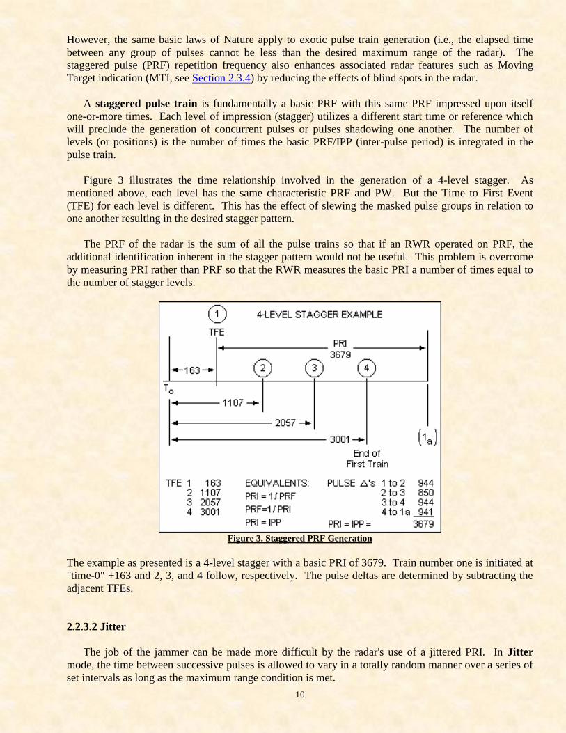
Figure 3 illustrates the time relationship involved in the generation of a 4-level stagger. As
mentioned above, each level has the same characteristic PRF and PW. But the Time to First Event
(TFE) for each level is different. This has the effect of slewing the masked pulse groups in relation to
one another resulting in the desired stagger pattern.
The PRF of the radar is the sum of all the pulse trains so that if an RWR operated on PRF, the
additional identification inherent in the stagger pattern would not be useful. This problem is overcome
by measuring PRI rather than PRF so that the RWR measures the basic PRI a number of times equal to
the number of stagger levels.
Figure 3. Staggered PRF Generation
The example as presented is a 4-level stagger with a basic PRI of 3679. Train number one is initiated at
"time-0" +163 and 2, 3, and 4 follow, respectively. The pulse deltas are determined by subtracting the
adjacent TFEs.
2.2.3.2 Jitter
The job of the jammer can be made more difficult by the radar's use of a jittered PRI. In Jitter
mode, the time between successive pulses is allowed to vary in a totally random manner over a series of
set intervals as long as the maximum range condition is met.
11
2.2.3.3 Stagger-Jitter Patterns
As long as the maximum range condition is met, an infinite number of PRI patterns can be generated
by combining stagger and jitter. The PRI can be modulated by a well-defined function: (a) a sliding PRI
very slowly increases/decreases the PRF, (b) a Ramp PRI decreases the interval with a cyclic ramp
function, and (c) a modulated PRI varies the intervals in a sinusoidal or triangular manner. Some
combinations seemed to be designed to foil processors which use digital analysis.
2.2.4 Missile Guidance
Guided missiles are not "guided" after a target. They do not pursue or chase an aircraft.
Instead, the fire control computer predicts an intercept point on some future part of the target flight
path based on the known flight parameters from the target tracking radar (TTR) and the known
maneuverable envelopes of both the target and the missile. [StealthSkater note: in early practice
encounters, the AV-8 Harrier used its 2-D inflight engine vectoring to consistently break the radar
lock from a F-14 Tomcat interceptor. The Harrier made abrupt "jumps" in altitude rather than
the conventional ones that normal aerodynamic mathematics allowed (and which the F-14's radar
was programmed with).]
Missiles are like guns in that both are fired at a "lead-angle" point. The missile is accelerated
(boosted) for the brief initial phase of its flight after which it can never again speed up. It is accelerated
toward the predicted intercept point after which it is only capable of slight course corrections to keep it
centered on the intercept point.
2.2.4.1 Command Guidance
For a guided missile to intercept its target, it must know at all times where the intercept point is in
relation to the missile itself. The simplest method for the missile is a separate transmitter (located at or
near the TTR) which sends coded guidance commands (e.g., fly left, fly up, etc.) to the missile. That is,
the missile is radio-controlled just as are model airplanes.
This approach has the advantage of a cheap expendable (the missile) and a guidance signal (the "up-
link") almost immune to target jamming since the missile receiving antenna can be highly directional,
aft-looking which allows guidance of the missile by manual mode and optical target tracking when the
primary tracker is jammed or otherwise inoperative.
It has the serious disadvantage that the ground site must track the missile in order to generate the
uplink (error correction) commands. As the missile and target approach the intercept point, the missile
tracker (the MTR) must point directly at the target and hence is highly susceptible to any jamming
source on the target. A second weakness of this system is that since the missile itself never sees the
target, some sort of self-fuzing device must be carried on the missile to reduce miss distance. Therefore,
this system is vulnerable to countermeasures at three points: (1) the TTR, (2) the MTR, and (3) the fuze.
12
2.2.4.2 Homing Guidance
A variation of command guidance is widely deployed. The MTR is replaced by a high-power
continuous wave illuminator (CWI) radar which is slaved and bore-sited to the TTR. The missile homes
on the Doppler return from the target (see Section 2.4.2).
This approach is still vulnerable in 3 places. The major difference is that no guidance commands are
transmitted. Since the CWI is not an MTR, RWR terminology uses Missile Guidance Radar (MGR) to
designate all radars used by an RWR to resolve identifications.
2.2.4.3 Beam Rider Guidance
The third method of guidance is the "beam rider" in which the SAM flies up the beam of the TTR.
An onboard flight computer keeps the missile centered in the tracking beam by use of aft-looking
antennae. Since a target tracking beam must be quite small to ensure track accuracy, the ground site
normally uses a broad-beamed, low-power radar to "capture" the missile during the initial flight stage
and guide it into the tracking beam. (This system requires the missile to be in a constant turn as it flies
up the tracking beam to the target. It is a maneuver which becomes quite severe during the terminal
flight stage and may exceed the physical limitations of the missile -- particularly if the target "jinks".)
The capture beam is immune to target jamming since it has no receiver and the missile antennae can
be highly directional aft. Miss distance improvement of this system also requires an onboard fuzing
device. Thus, this approach simplifies the ground site by making the expendable more costly and it has
fewer jamming points: (1) the TTR and (2) the fuze.
The most serious disadvantage to beam riding is that the TTR must be on the air for missile guidance
even if tracking is accomplished by alternate means. No TTR -- no guided missile.
2.2.4.4 Fuse Jamming
Both command guidance and beam riders are susceptible to tracking radar and fuze jamming. The
simplest fuze is the radar proximity type which sends out a rather broadbeamed signal and measures the
power in the target echoes.
For a given target size and fuse, transmitter power returned from the target when the missile is
within the kill radius of the warhead can be well-calculated. By using a simple threshold detector in the
fuze receiver, the warhead is detonated when the kill radius is reached. This system can be jammed by
making the target return much larger than normal so that the warhead is detonated prematurely outside
the kill radius.
In countermeasures terminology, fuze jamming is an "end game reaction" -- i.e., a last ditch attempt.
End game can be avoided in both these guidance systems if the tracking radars can be defeated either
completely or by accuracy degradation. Most ECM systems are dedicated to the track radars since
target carried fuze jammer transmitters can act as fuze homing devices.
13
2.2.4.5 Missile Guidance Correlation
Of the guidance methods, command guidance is traditionally the most commonly encountered in a
threat scenario. In the case of pulsed TTR and MGR, it should be noted that synchronization of the 2
radars and the missile correction commands requires that some relationship exist between the PRF of
both radars. Thus it is possible in the case of an all-pulse system to determine if a TTR has entered the
missile launch (ML) state by testing time correlation between the TTR and MGR pulse trains.
For an RWR to detect the ML state on a homing guidance missile system, the CWI must be received.
This detection requires a superheterodyne receiver input to the RWR. On a pure CW system,
microwave detection of an ML state may not be possible.
Determining ML from the proximity fuze signal is questionable since fuze power is so low that no
real warning will be obtained. That is, fuze power is 100-200 watts broad-beamed. Detection of a
Mach-2 (2,000 feet per second) missile at a ½mile would give a 1-to-2 second warning. The aircrew
would only be able to "die tense".
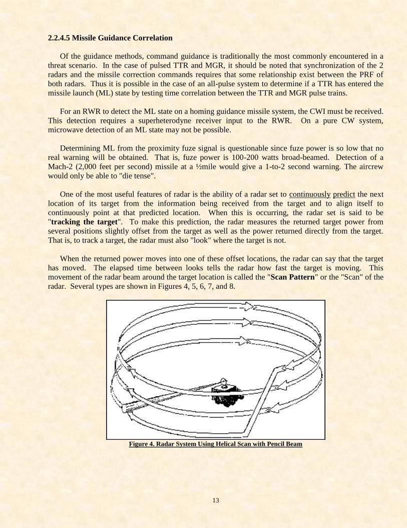
One of the most useful features of radar is the ability of a radar set to continuously predict the next
location of its target from the information being received from the target and to align itself to
continuously point at that predicted location. When this is occurring, the radar set is said to be
"tracking the target". To make this prediction, the radar measures the returned target power from
several positions slightly offset from the target as well as the power returned directly from the target.
That is, to track a target, the radar must also "look" where the target is not.
When the returned power moves into one of these offset locations, the radar can say that the target
has moved. The elapsed time between looks tells the radar how fast the target is moving. This
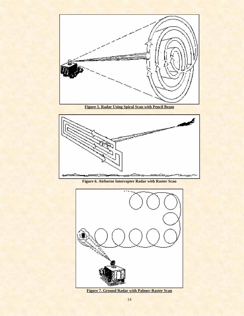
movement of the radar beam around the target location is called the "Scan Pattern" or the "Scan" of the
radar. Several types are shown in Figures 4, 5, 6, 7, and 8.
Figure 4. Radar System Using Helical Scan with Pencil Beam
14
Figure 5. Radar Using Spiral Scan with Pencil Beam
Figure 6. Airborne Intercepter Radar with Raster Scan
Figure 7. Ground Radar with Palmer-Raster Scan
15
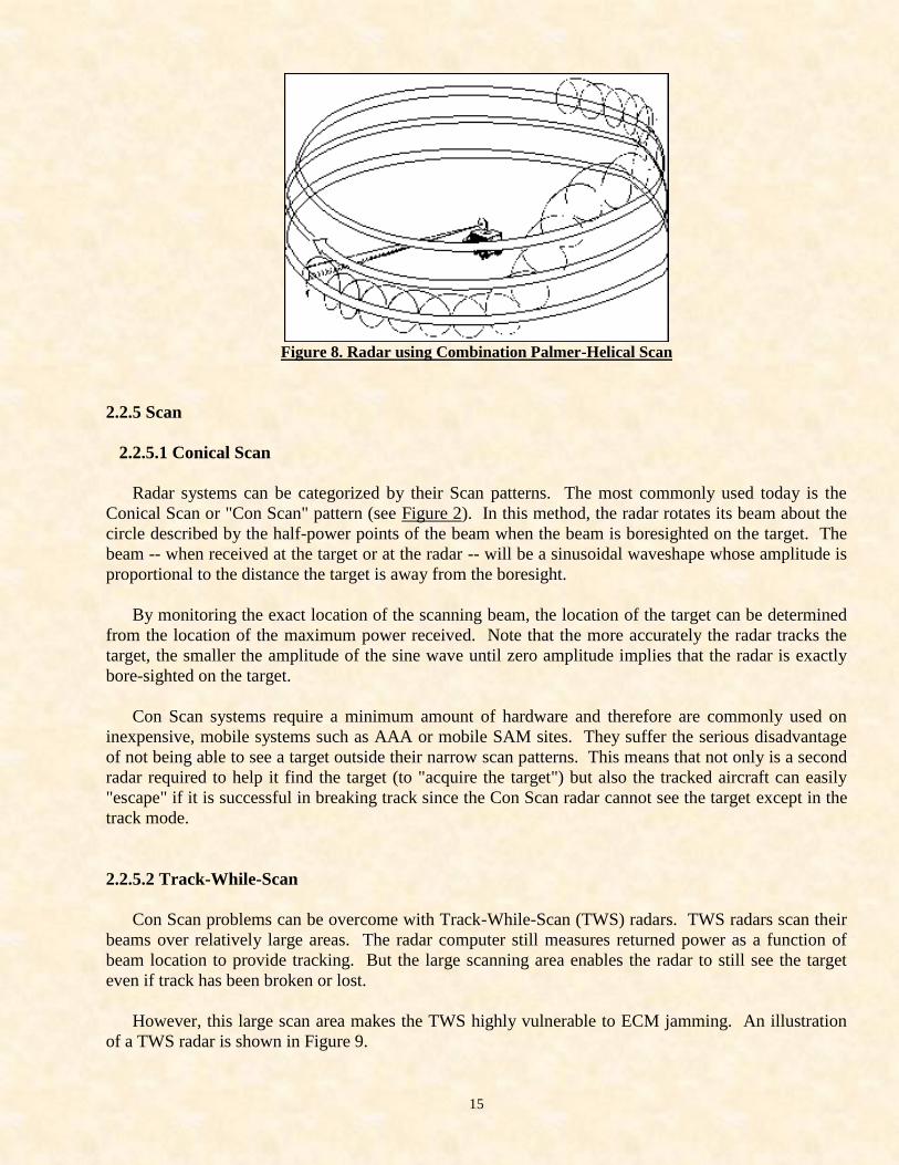
Figure 8. Radar using Combination Palmer-Helical Scan
2.2.5 Scan
2.2.5.1 Conical Scan
Radar systems can be categorized by their Scan patterns. The most commonly used today is the
Conical Scan or "Con Scan" pattern (see Figure 2). In this method, the radar rotates its beam about the
circle described by the half-power points of the beam when the beam is boresighted on the target. The
beam -- when received at the target or at the radar -- will be a sinusoidal waveshape whose amplitude is
proportional to the distance the target is away from the boresight.
By monitoring the exact location of the scanning beam, the location of the target can be determined
from the location of the maximum power received. Note that the more accurately the radar tracks the
target, the smaller the amplitude of the sine wave until zero amplitude implies that the radar is exactly
bore-sighted on the target.
Con Scan systems require a minimum amount of hardware and therefore are commonly used on
inexpensive, mobile systems such as AAA or mobile SAM sites. They suffer the serious disadvantage
of not being able to see a target outside their narrow scan patterns. This means that not only is a second
radar required to help it find the target (to "acquire the target") but also the tracked aircraft can easily
"escape" if it is successful in breaking track since the Con Scan radar cannot see the target except in the
track mode.
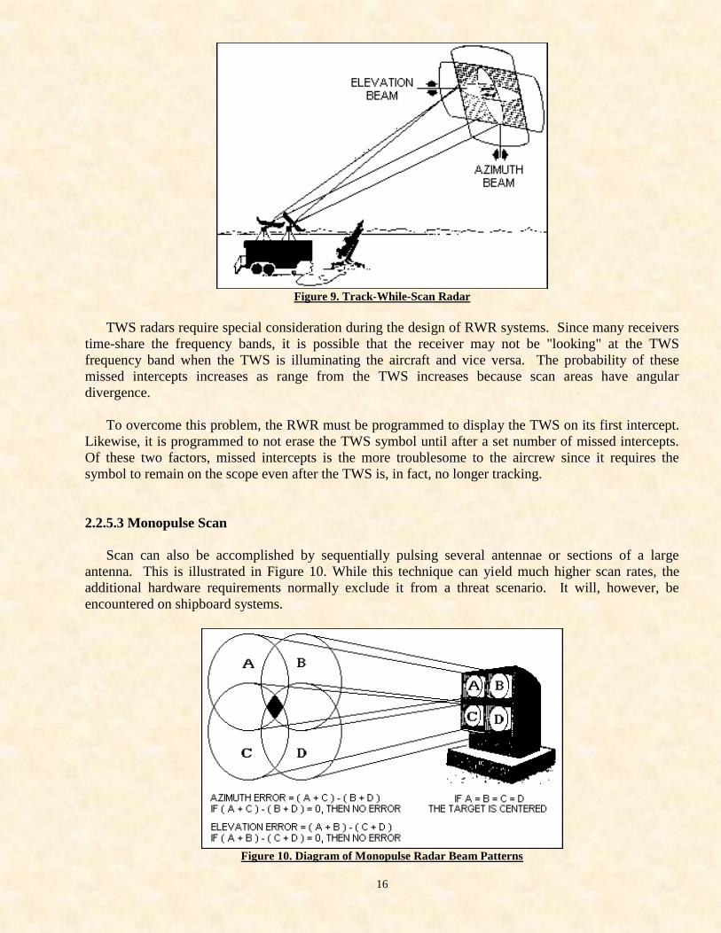
2.2.5.2 Track-While-Scan
Con Scan problems can be overcome with Track-While-Scan (TWS) radars. TWS radars scan their
beams over relatively large areas. The radar computer still measures returned power as a function of
beam location to provide tracking. But the large scanning area enables the radar to still see the target
even if track has been broken or lost.
However, this large scan area makes the TWS highly vulnerable to ECM jamming. An illustration
of a TWS radar is shown in Figure 9.
16
Figure 9. Track-While-Scan Radar
TWS radars require special consideration during the design of RWR systems. Since many receivers
time-share the frequency bands, it is possible that the receiver may not be "looking" at the TWS
frequency band when the TWS is illuminating the aircraft and vice versa. The probability of these
missed intercepts increases as range from the TWS increases because scan areas have angular
divergence.
To overcome this problem, the RWR must be programmed to display the TWS on its first intercept.
Likewise, it is programmed to not erase the TWS symbol until after a set number of missed intercepts.
Of these two factors, missed intercepts is the more troublesome to the aircrew since it requires the
symbol to remain on the scope even after the TWS is, in fact, no longer tracking.
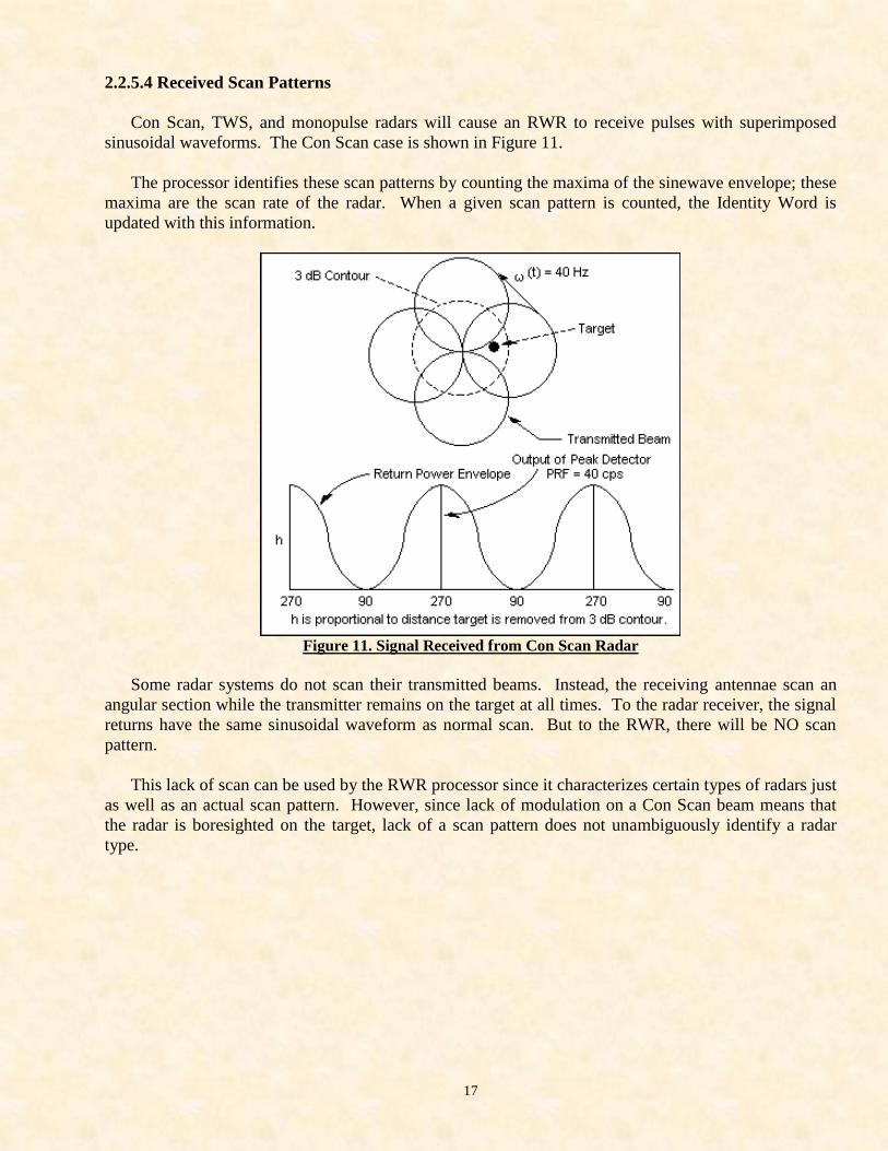
2.2.5.3 Monopulse Scan
Scan can also be accomplished by sequentially pulsing several antennae or sections of a large
antenna. This is illustrated in Figure 10. While this technique can yield much higher scan rates, the
additional hardware requirements normally exclude it from a threat scenario. It will, however, be
encountered on shipboard systems.
Figure 10. Diagram of Monopulse Radar Beam Patterns
17
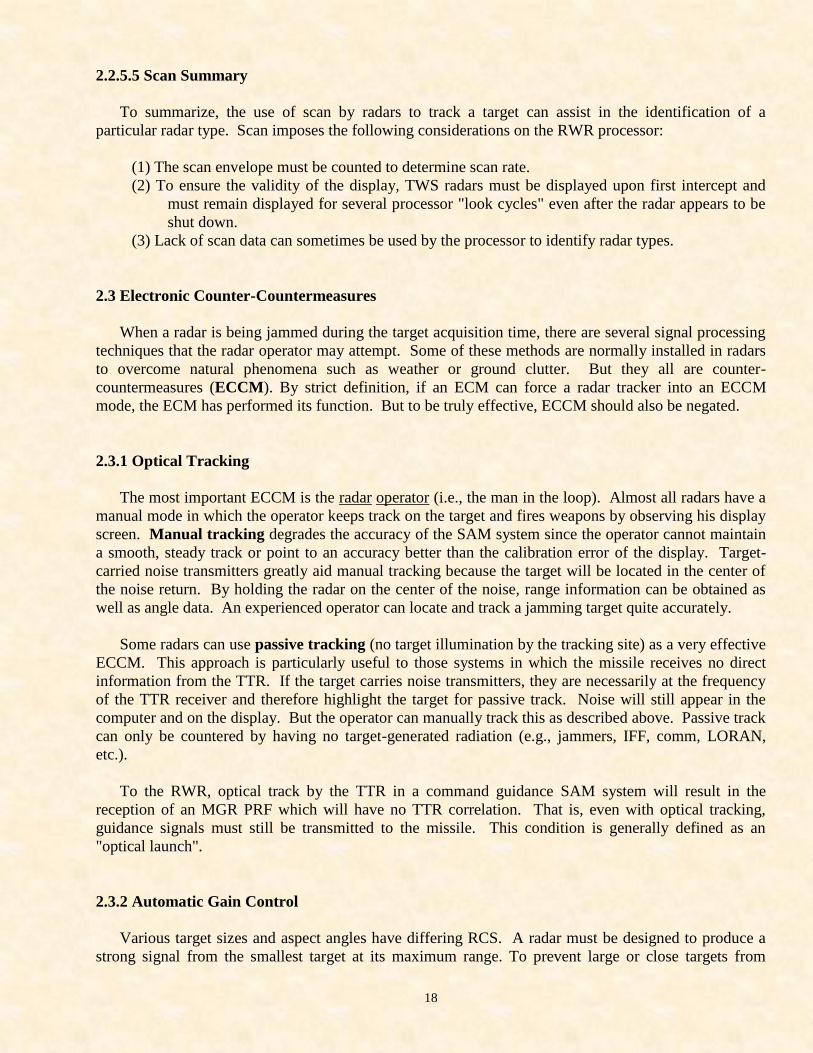
2.2.5.4 Received Scan Patterns
Con Scan, TWS, and monopulse radars will cause an RWR to receive pulses with superimposed
sinusoidal waveforms. The Con Scan case is shown in Figure 11.
The processor identifies these scan patterns by counting the maxima of the sinewave envelope; these
maxima are the scan rate of the radar. When a given scan pattern is counted, the Identity Word is
updated with this information.
Figure 11. Signal Received from Con Scan Radar
Some radar systems do not scan their transmitted beams. Instead, the receiving antennae scan an
angular section while the transmitter remains on the target at all times. To the radar receiver, the signal
returns have the same sinusoidal waveform as normal scan. But to the RWR, there will be NO scan
pattern.
This lack of scan can be used by the RWR processor since it characterizes certain types of radars just
as well as an actual scan pattern. However, since lack of modulation on a Con Scan beam means that
the radar is boresighted on the target, lack of a scan pattern does not unambiguously identify a radar
type.
18
2.2.5.5 Scan Summary
To summarize, the use of scan by radars to track a target can assist in the identification of a
particular radar type. Scan imposes the following considerations on the RWR processor:
(1) The scan envelope must be counted to determine scan rate.
(2) To ensure the validity of the display, TWS radars must be displayed upon first intercept and
must remain displayed for several processor "look cycles" even after the radar appears to be
shut down.
(3) Lack of scan data can sometimes be used by the processor to identify radar types.
2.3 Electronic Counter-Countermeasures
When a radar is being jammed during the target acquisition time, there are several signal processing
techniques that the radar operator may attempt. Some of these methods are normally installed in radars
to overcome natural phenomena such as weather or ground clutter. But they all are counter-
countermeasures (ECCM). By strict definition, if an ECM can force a radar tracker into an ECCM
mode, the ECM has performed its function. But to be truly effective, ECCM should also be negated.
2.3.1 Optical Tracking
The most important ECCM is the radar operator (i.e., the man in the loop). Almost all radars have a
manual mode in which the operator keeps track on the target and fires weapons by observing his display
screen. Manual tracking degrades the accuracy of the SAM system since the operator cannot maintain
a smooth, steady track or point to an accuracy better than the calibration error of the display. Target-
carried noise transmitters greatly aid manual tracking because the target will be located in the center of
the noise return. By holding the radar on the center of the noise, range information can be obtained as
well as angle data. An experienced operator can locate and track a jamming target quite accurately.
Some radars can use passive tracking (no target illumination by the tracking site) as a very effective
ECCM. This approach is particularly useful to those systems in which the missile receives no direct
information from the TTR. If the target carries noise transmitters, they are necessarily at the frequency
of the TTR receiver and therefore highlight the target for passive track. Noise will still appear in the
computer and on the display. But the operator can manually track this as described above. Passive track
can only be countered by having no target-generated radiation (e.g., jammers, IFF, comm, LORAN,
etc.).
To the RWR, optical track by the TTR in a command guidance SAM system will result in the
reception of an MGR PRF which will have no TTR correlation. That is, even with optical tracking,
guidance signals must still be transmitted to the missile. This condition is generally defined as an
"optical launch".
2.3.2 Automatic Gain Control
Various target sizes and aspect angles have differing RCS. A radar must be designed to produce a
strong signal from the smallest target at its maximum range. To prevent large or close targets from
19
saturating the receiver and flooding the display screen, Automatic Gain Control (AGC) is used to vary
the sensitivity in high signal areas.
RCS is additive in one resolution cell. If there are 20 square meters of noise and a l0-square-meter
target in the same resolution cell, the radar will see a 30-square-meter return. If there is a large area of
noise (ECM, weather, ground return, etc.) of 20-square-meter RCS, the gain of the radar receiver can be
set for a threshold of 20 square meters and only the 10-square-meter target will then be displayed.
Jammer return can be greatly reduced in this manner. But if the jamming power is varied rapidly,
the AGC will be in a constant state of unbalance which can degrade tracking accuracy.
2.3.3 Instantaneous Automatic Gain Control
When AGC is performed on a pulse-to-pulse basis it is called Instantaneous Automatic Gain
Control (IAGC). AGC varies gain based on the return from a broad area while IAGC allows mapping
of the high noise area. IAGC subtracts the power of the first pulse from the second. If the noise is
uniform, it will be "erased" from the receiver and display, leaving any targets that may be in the noise
area.
2.3.4 Moving Target Indicator
When a target moves with respect to the radar transmitter, the reflected signal receives a frequency
(phase) shift proportional to v/c where v is aircraft velocity and c is the speed-of-light. At microwave
frequencies and fighter airspeeds, the Doppler shift is up to 20 kHz. Radars can use this
frequency/phase shift as an excellent tracking method and ECCM.
The period (wavelength) of 20 kHz is 200 microseconds. To recover this 20 kHz shift from the
original radar signal, the original must be CW or a pulse train with pulses of a period several times
longer than 200 microseconds (a "pulse Doppler" radar). On regular pulsed radar, the nominal quarter
microsecond pulses will contain very little of the Doppler shift per pulse. But they will have measurable
phase differences. Systems which recover the shift as a discrete frequency are called Doppler radars
while those circuits which only measure pulse-to-pulse frequency/phase differences are called Moving
Target Indicators (MTI).
Stationary targets return radar signals -- pulse-to-pulse -- of fixed phase. The output of a phase
detector is a signal whose amplitude is directly proportional to the phase difference of its inputs. MTI
uses a phase detector to provide zero amplitude (no input) signals to the tracking computer and display
screens from fixed targets such as weather and ground return.
A simpler way to understand MTI is in terms of scintillation. As an aircraft flies through a SAM
area, its aspect angle and hence its RCS is constantly changing (i.e., the return scintillates). Note that
MTI differs from IAGC in that the pulse-to-pulse comparison is for phase (scintillation) differences
instead of amplitude differences.
Another method of MTI is to compare the target location on a pulse-to-pulse basis. If the target
return occurs at exactly the same time (range) on 2-or-more successive pulses, it did not move and hence
is not applied to the computer and display screen.
20
2.3.5 Lobe on Receive Only (LORO)
Recall that to predict the future location of a target (to track) requires that the radar look at areas
where the target is not located. When this scanning is accomplished with the radiated beam, large angle
targets such as chaff clouds can create complete radar "white-out". That is, large areas of reflective
noise will be seen by the receiver. Also, RWR indications can be obtained before actual target lock-on.
These problems can be overcome by scanning only the receiving antennae and using a separate
transmitting antenna pointed only at the target. This scheme is called Lobe On Receive Only (LORO).
In a LORO system, a transmitting antenna emits a few "exploratory" pulses along a direction
obtained from an acquisition radar. These exploratory pulses are the acquisition mode of the TTR. That
is, in its acquisition mode, the small-beamed TTR must scan the large location segment provided by the
acquisition radar. In radars equipped with Fast Time Constant (FTC -- see next section), the return
pulse is applied to a differentiator of extremely short time constant. When the pulse is received, it is
"cut-off" on the eading edge and only that portion is fed to the computer. This allows the radar to
effectively track on the leading edge of the target. FTC does not improve the range resolution (and
hence the res cell). But it can prevent any countermeasures aft of the target but in the same res cell as
the target (such as chaff) from interfering with the radar receiver.
The receiving antennae scan their sector for the target return due to these exploratory pulses. As the
power centroid is located, the center of the receiving pattern is brought onto the target. The transmitting
antennae -- which is slaved to the receiving antennae -- is then pointing directly at the desired target and
only that target is radiated during tracking . This approach allows a very small radiated beam. But the
resolution cell of the system is still that of the receiving antenna or antennae.
Note that LORO systems are ideally suited for passive tracking of any signals generated onboard the
target.
2.3.6 Fast Time Constant
The range accuracy of a radar is a measure of the time of flight of microwave pulse to a target. Upon
transmit, a clock starts and it stops when a return pulse is received. The range is equal to 1/2 this time.
2.4 Types of Radars
2.4.1 Pulse Radars
These were fully discussed in Section 2.2. These are the most commonly used because the S/N ratio
inherent in pulsed operation minimizes the need for high average power. However, due to the reduced
ECM vulnerability of CW type radars, many of the new threat systems are using CW.
2.4.2 CW Radars
When a reflecting target moves with respect to the receiver, the returned signal will have a frequency
shift proportional to v/c where v is the target velocity and c is the speed-of-light. The frequency shift
increases for inbound targets and decreases for outbound targets by an amount proportional to the radial
range change. That is, crossing targets will have low Doppler shifts while inbound/outbound targets
21
have the maximum Doppler shift. If a target orbits a radar at a constant radius, there is no Doppler shift.
At microwave frequencies and fighter speeds, Doppler shift varies up to 20 kHz.
The radar receiver can recover the Doppler shift by mixing the transmitted and received signals.
Because of the low frequency of the shift with respect to the transmitted frequency, the transmitter must
operate as a continuous wave (CW) signal source or in a pulse mode with pulses many times longer
than the period of 20 kHz (Pulse Doppler).
In the CW case, range resolution is not possible but in Pulse Doppler range can be obtained by
transmitting short pulses between the "interrupted CW" pulses. But the change in Doppler shift is
directly proportional to range rate (dR) so that the radar can recover dR -- a quantity which not only
yields antenna slew rates but also precisely locates when R=0 is identical to dR=0 and thereby greatly
improve missile miss distance.
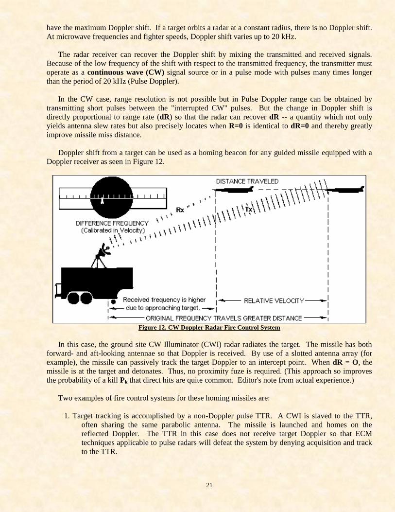
Doppler shift from a target can be used as a homing beacon for any guided missile equipped with a
Doppler receiver as seen in Figure 12.
Figure 12. CW Doppler Radar Fire Control System
In this case, the ground site CW Illuminator (CWI) radar radiates the target. The missile has both
forward- and aft-looking antennae so that Doppler is received. By use of a slotted antenna array (for
example), the missile can passively track the target Doppler to an intercept point. When dR = O, the
missile is at the target and detonates. Thus, no proximity fuze is required. (This approach so improves
the probability of a kill Pk that direct hits are quite common. Editor's note from actual experience.)
Two examples of fire control systems for these homing missiles are:
1. Target tracking is accomplished by a non-Doppler pulse TTR. A CWI is slaved to the TTR,
often sharing the same parabolic antenna. The missile is launched and homes on the
reflected Doppler. The TTR in this case does not receive target Doppler so that ECM
techniques applicable to pulse radars will defeat the system by denying acquisition and track
to the TTR.
22
2. The TTR itself as well as the missile has a Doppler receiver and tracks the target in frequency.
In this approach, the TTR obtains initial tracking data from a pulse radar or from manual
operation after which it can auto-track the Doppler. That is, the CWI is the TTR.
CWI TTRs are ideally suited for 2 excellent ECCM techniques -- coherency and home-on-jam. A
continuous wave can be modulated by an ultra-low frequency signal. If an 85 Hz modulation is used, the
period for one cycle is about 2,000 nm. Thus at normal SAM racking ranges, the phase of the 85 Hz
will be changed very little by the round-trip distance. The transmitted and received signals will be in
phase (i.e., coherent).
This modulation is called the COHO signal. Any signal (including jamming signal) must be
coherent to pass the radar receiver. Since the COHO phase can be easily randomly switched, the active
countermeasure is almost negated as an operational system.
The homing missile receives the transmitted signal -- with COHO -- in the aft antennae and the
reflected Doppler signal -- with COHO -- in the forward antenna. When the two COHOs are in phase,
the missile has identified the correct target. (The correct radar is identified by a modulated code
frequency at the aft antenna.) The missile can now fly to the target by its own steering computer,
needing no other commands from the radar.
If the target attempts to jam the TTR, the missile will see this jamming in its forward antenna which
is locked on the target. If the jamming is not coherent, COHO lock will reject it. Alternatively, the
missile can divert to a home-on-jam (HOJ) mode and track the jamming signal to the target. That is, due
to the COHO capability of a CWI, target-generated ECM can actually be a highly directional homing
beacon for the missile.
It should be noted that a pure CW beam conveys very little intelligence to the missile. As already
discussed, anti-jamming signals can AM the CW, radar-missile identity codes can FM it. A range
approximation can be determined from a ramp function which FMs the signal and phase modulation can
also be used as an ECCM device. Thus, a spectrum analyzer display of an actual SAM CW signal
would show a complex AM-FM-FM-PM continuous wave. For Pulse Doppler such as airborne
interceptor pulse Dopplers (AIPDs), this same signal would be interrupted periodically for transmission
of several ranging pulses or pulse groups (i.e., stagger, jitter or both).
2.4.3 Radars Other Than SAM Fire Control
Any air defense network will be composed of many radars other than those designed for weapon fire
control.
Except for AAA and AI, these additional radars are generally characterized by low frequency, large
beams, and no auto-track capability. Some of the radars in this group are Acquisition, Early Warning,
Height Finders, GCI, and GCA.
2.4.3.1 Early Warning Radars
Because fire-control radars require very small beams for location accuracy, they must depend on other
radars for initial target detection and location. The Early Warning (EW) radar is typically a low
frequency (100-1000 Hz), large beam (6-16 degree), long range (200-or-more nautical miles) system
capable of searching a full 360-degree Az for initial target detection and heading.
23
Therefore, any ECM which does not make the target disappear will only assist in the EW mission
due to the beaconing effect of jammer transmitters. Although these radars normally employ AGC and
MTI (see Sections 2.3.2 and 2.3.4), they represent no real threat to aircraft since they cannot accurately
direct weapon fire.
2.4.3.2 Acquisition Radars
After the EW radar detects the target, the Acquisition (Acq) radar will further localize the position
for the small beam trackers. These radars are characterized by medium (3-6 degree) beams of medium
(800 kHz to 8,000 kHz) frequencies and no auto-track capability. They generally search an Az segment
determined by the EW radar.
Because these radars are very similar to fir- control systems, they can be jammed by the same
techniques and tactics as those for fire control if the appropriate frequency device is carried. Denying
Acq radar coordinates to a SAM radar forces him into a manual target acquisition mode which -- due to
the small beam SAM radar -- can greatly increase minimum acquisition time. With some systems, loss
of acq results in denial of track.
2.4.3.3 Height Finder Radars
Height Finder (HF) systems are used to provide El data on the EW and Acq Az target data. These
radars have characteristics very similar to Acq radars except that the smallest dimension of their beams
will be vertical for best El resolution.
For maximum El uncertainty, then, the aircraft formation should be "stacked". But since this system
also has no autotrack or associated weapon, it presents no real threat. These radars are primarily used
for vectoring airborne interceptors.
2.4.3.4 Ground Controlled Intercept Radars
Ground-Controlled Intercept (GCI) systems are usually composed of acquisition and height finder
radars. They are used to vector interceptor aircraft to an intruding force.
2.4.3.5 Ground Controlled Approach Radars
Ground-Controlled Approach (GCA) radars have parameters very similar to those of GCI, Acq, and HF.
They differ from those systems primarily in their display units. GCA scopes are pre-marked with the
appropriate glide angle for the site. ECM can easily be used against these radars to force interceptor
aircraft to use visual approaches.
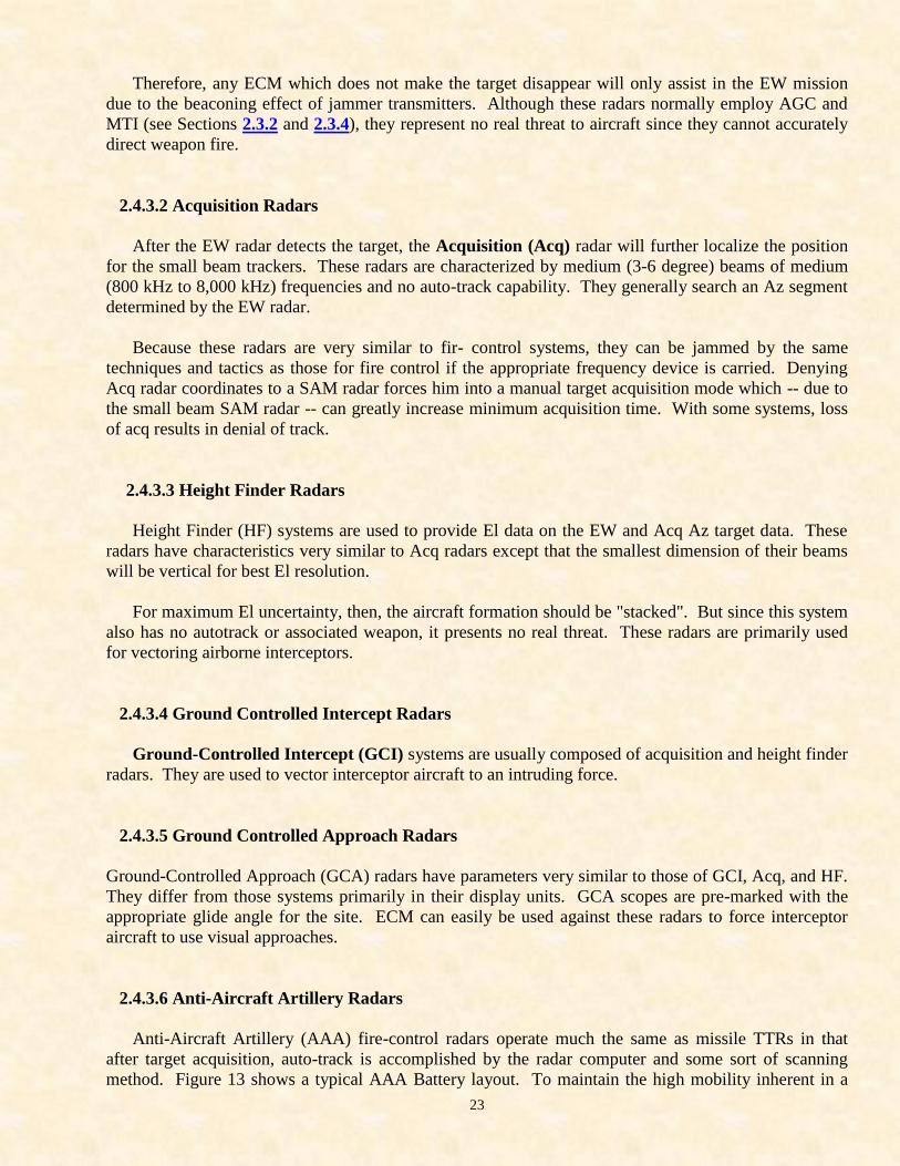
2.4.3.6 Anti-Aircraft Artillery Radars
Anti-Aircraft Artillery (AAA) fire-control radars operate much the same as missile TTRs in that
after target acquisition, auto-track is accomplished by the radar computer and some sort of scanning
method. Figure 13 shows a typical AAA Battery layout. To maintain the high mobility inherent in a
24
simple gun system, the radars have small dishes with medium beams (1-5 degrees) and wide frequency
ranges (800 MHz to 20 GHz) with conical scanning (Con Scan).
Figure 13. Typical AAA Battery in Operation
2.4.3.7 Airborne Interceptor Radars
Airborne Fire Control (AI) systems are used for Airborne Interceptor Missiles (AIM) guidance. The
cockpit operator manually acquires the target by training the antenna. Auto-track is then usually
accomplished by some scanning method or frequency (Doppler) track.
2.4.3.8 Terminal Defense Radars
Terminal defense radars are the fire control systems for SAMs and AAAs. As such, they were
discussed earlier in this work under those headings.
3.0 RADAR WARNING RECEIVER SYSTEMS
The following is excerpted from an early report from Dalmo Victor -- the pioneer developer of
digital (reprogrammable) radar warning receivers. The report has received wide circulation because it
very concisely describes a digital RWR to those who now understand the principles of radar described in
the previous sections of this tutorial.
To completely identify an electromagnetic signal received at a remote point as originating from a
particular radar system at a particular location, the following seven parameters must be measured:
25
1. Frequency
2. Pulsewidth
3. PRF patterns
4. Missile guidance
5. Scan pattern
6. Power density (transmitter power and beamwidth)
7. Angle-of-arrival.
These "fingerprints" identify and locate the system which generated them. Since the parameters of
all radar systems are fairly well known, a digital radar warning receiver identifies a particular radar by
storing its known fingerprints in digital form in a memory bank for comparison with incoming signals.
It is the function of the signal processor, then, to receive unknown signals, digitize them into a "word
format" and present them to the identification words stored in its memory for matching. When a match
is found to exist, the processor display circuits present an alphanumeric visual warning of the location
and threat status.
To use this stored data, the incoming signal must be processed to generate a computer word which
contains the following identification data:
Freq / PW / PRF (1)
A receiver can be designed to determine each fingerprint to the accuracy to which they are known.
But any operational self-protection receiver must be designed to minimize equipment size and
complexity and maximize aircrew simplicity. The frequency measuring device can be simplified by
identifying only the band in which the radar exists. Likewise, since radar can be classified as threat/no
threat by PW (threat radars have short pulsewidths), the pulsewidth measurements can be simplified to
Long/Short. Then if an emitter of a precisely measured PRF is located within a frequency band and has
an acceptable pulsewidth, it is assumed to be at the discrete frequency/pulsewidth which corresponds to
that PRF. So term (1) becomes:
Freq Band / PW Band / PRF (2)
This simplification allows a great deal of reduction in hardware. But it causes some ambiguous
identifications since radars in the same Freq/PW bands can have overlapping PRF.
Ambiguities can be resolved for missile fire control radars by correlating the missile guidance signal
(the "uplink") with the fire-control radar with which it is known to be used. Now the word becomes:
Freq Band / PW Band / PRF / MG Correlation (3)
Note that if a SAM signal can be resolved, it is resolved prior to -- or at the time that -- it becomes a
real threat. That is, when missile guidance is activated, the system is ready for firing or the missile is in
flight and the warning receiver has resolved its ambiguity to a true alert.
Since threat (i.e., fire-control) radars must have some sort of scan method for auto-tracking,
transmitted scan patterns (or the absence of them) can sometimes be used to help resolve ambiguities.
Scan resolution can be particularly useful in identifying AAA radars. The word now becomes:
Freq Band / PW Band / PRF / MG Correl / Scan (4)
26
Many emitters use staggered or jittered pulse trains or a combination of the two to optimize their
own capabilities. Thus, these PRF patterns can sometimes be used to resolve ambiguous identifications:
Freq Band / PW Band / PRF Patterns / MG Correl / Scan (5)
The term (5) above is the processed identity word that is applied to the digital memory for threat
matching. This format should not be interpreted as the order in which the various fingerprints are
actually processed. Instead, most of them are transmitted and processed simultaneously. But if they are
not, each parameter can be added to the basic word (1) as they are applied to the transmitter.
It is important to note that (5) will not always unambiguously identify a threat since the radar
windows imposed by Nature and state-of-the-art cause many threats to have closely related fingerprint
sets. When (5) results in an ambiguity, the RWR uses additional receivers to provide additional
"resolving power" on the parametric data of (5).
To determine the location of the radar, azimuth and range must be added to (5). Azimuth can be
obtained from DF antennae while approximate range can be determined from the received power level.
Thus, (5) becomes:
Freq Band / PW Band / PRF Patterns / MG Correl / Scan / Az / Pwr (6)
where the first 5 terms are used for Identification and the last 2 terms for Location.
The characteristics of the weapons associated with radar systems are also well known. To enable the
warning receiver to display its data in the most meaningful manner, the Power information can be
weighted by known weapon lethality to obtain a range display which is a function of range and relative
danger. (6) becomes:
Freq Band / PW / PRF Patterns / MG Correl / Scan / Az / Pwr / Lethality (7)
where the first 5 terms again are used for Identification and the last 3 terms for Relative Location.
With term (7) the identification is complete and the appropriate symbol is displayed on the Azimuth
Indicator. At the same time, the PRF is "stretched" and applied to the aircraft ICS as an audio tone or
alert as directed by the aircrew.
4.0 COCKPITOLOGY
It should be obvious to the reader at this point that the many radars in an air defense network have
similar parameters. From Section 3 of this tutorial, signal processing techniques used by RWR systems
cause additional parameter overlaps. Thus, ambiguous identifications will always exist in RWRs (i.e.,
the computer has used its best logical analysis to eliminate most radar types, but several candidates still
exist). These are displayed on the RWR screen as alternating symbols and the aircrew must make the
final identification. Such identifications are called "ambiguities".
Cockpitology is the study of the integration of the aircrew with the mission, ECM gear, and RWR so
as not to interfere with his combat role but yet let him translate ambiguities into self-protect ECM or
maneuvers. It differs from present day man-machine interface studies in that it concentrates on defining
very simple rules for interpreting ambiguities based on data available to the pilot only after his mission
27
is scheduled and while it is being flown. Effective utilization of an RWR requires a thorough
understanding of the cockpitology of that system.
5.0 GLOSSARY OF ELECTRONIC WARFARE
ASW: anti-submarine warfare
BEAM RIDER: weapon or missile which through on-board electronics follows an electromagnetic or
light beam
CHAFF: small metallic dipoles that resonate at the radar frequency and cause large radar back scatter
CLUTTER: the presence of reflections (echoes) from objects in the area of the target
COMMAND GUIDANCE: a data link whose purpose is the transmission of information from one
system to another system.
CONTINUOUS WAVE (CW): continuous flow of electromagnetic energy (non-pulsed)
DATA LINK: the system by which information is transferred between 2 locations. Generally refers to
RF or optical transmitting and receiving equipment
DATA RATE: the rate at which data can be converted, transmitted, received, and reconstructed
DETECTION: acquisition of an electromagnetic signal with the same output characteristics as the
original transmitted data
DOPPLER (EFFECT): continuous wave (CW) doppler radar modules are sensors which measure the
shift in frequency created when an object (being "illuminated" by energy waves) moves. A
transmitter emits energy at a specific frequency which -- when reflected -- can indicate both
speed and direction of that target.
For instance: DFT = 2TF (v/c) cos(A) where DFT is the doppler frequency shift, TF is the transmitter
(or head) frequency, v is the velocity of the target, c is the speed-of-light, and A is the angle
between the perpendicular axis of the transmitter and the direction of the target. When objects
move closer to the doppler source, they increase in shift (positive value. And when they move
further away, they decrease in shift (negative values). Hence the expressions "up Doppler" or
"down Doppler" as used so familiarly to signify movements of a target.
DUTY CYCLE: the percentage of time a device or system is active relative to continuous operation
FREQUENCY AGILITY: the rapid and continual shifting of a transmitter's mean frequency -- generally
to avoid jamming
FREQUENCY BAND: a continuous and specific range of frequencies
FREQUENCY BANDPASS: the number of Hertz where maximum output is obtained between 2 limits
usually defined and bounded by lower and upper half-power (3 dB) points
28
FREQUENCY HOPPING: an anti-jamming technique used by a radar system. The carrier frequency of
the pulsed transmissions are periodically or continuously shifted within limits on each successive
pulse.
FREQUENCY MODULATION (FM): the modulation of a sine wave carrier so that its instantaneous
frequency differs from that carrier by the amount proportional to the modulating wave
FREQUENCY SHIFT KEYING (FSK): frequency modulation in which the modulating wave shifts the
output frequency between predetermined values. The output wave has no phase discontinuity
FREQUENCY SPECTRUM: the entire range of frequencies of electromagnetic radiation
GAIN: any increase in power when energy is transferred from one point to another
IFF: Identification-Friend or Foe. A major problem in modern warfare is the inability to discriminate
between friendly and non-friendly forces. IFF equipment provides appropriate responses upon
interrogation.
JAMMER: a device used to deprive, limit or degrade the use of a communications system. Radio
frequency jammers include barrage, noise, discrete frequency repeater, and deceptive
equipments.
LEADING EDGE TRACKER: a tracking radar which obtains its data from the leading edge of the echo
pulse from the target
MISSILE LAUNCH DETECTION: Certain military aircraft are equipped with specialized receivers for
the purpose of detecting actual missile launch conditions.
MISS DISTANCE: the distance measured between the closest paths of a target and intercepter (i.e.,
aircraft and missile). One objective of Defensive ECM equipment is to increase the miss
distance to a safe distance if detection and launch cannot be prevented.
MODULATION: the variation of amplitude, frequency, or phase of an electromagnetic wave by
impressing another wave on it
NOISE: any unwanted electrical or mechanical disturbance which modifies the desired performance
NOISE FIGURE (N.F.): the ratio of the total noise at the output to the noise at the input of a device.
Generally attributable to the thermal noise of the signal source.
PASSIVE: an inert component which may control -- but does not create or amplify -- information for the
purpose of jamming
PHASE COHERENT: the continuous wave which has no discontinuity
PHASE LOCKED LOOP (P.L.L.): circuit in which the local oscillator is synchronized in frequency and
phase with the received signal
PSEUDO CW: method of pulse transmission which can be received and integrated in a CW receiver as a
normal CW signal
29
PULSE CODING: a technique which includes a variety of methods to change the transmitted waveform
and then decode upon reception
PULSE MODULATION: the modulation of a carrier by a series of pulses generally for the purpose of
transmitting data
PULSE POSITION MODULATION: the conversion of analog information to variation of pulse
positions versus time
PRF: Pulse Repetition Frequency. It is the frequency at which a pulse of certain width and amplitude is
repeated.
REFLECTIVITY: the measure of a surface or a device to reflect impinging energy
SCINTILLATION: random and usually small fluctuations of a received field about its mean value. Also
called "target glint" or "wande".
RADAR RELATED TERMS
ACQUISITION MODE: that mode of operation wherein the TTR scans its narrow beam over an angular
segment to initially acquire the target so that the track mode can be used.
ACQUISITION RADAR: those radars in an air defense network used to locate a target within an
angular segment (generally 5-to-10 degrees).
AIRBORNE FIRE CONTROL (AI) RADARS: those radars in an air defense network carried onboard
interceptor aircraft. Their small size and short range characterize them as high frequency, low
power, relatively large beam (3-degree) systems.
AIPD - AIRBORNE INTERCEPTOR PULSE DOPPLER: an airborne fire control radar which uses
pulse-doppler techniques
ANTI-AIRCRAFT ARTILLERY (AAA) RADARS: those radars in an air defense network used to
direct gunfire.
BOMBING/NAGIVATION RADAR: used to guide an aircraft to a specific point and compute an
optimum weapon release cue to hit the point.
CONTINUOUS WAVE ILLUMINATOR (CWI): that radar in an air defense network which is used to
illuminate a target with high-power CW so that missiles may home on the reflected CW energy.
CONTRAST TRACKER: a target tracking system which uses light as an illuminating signal and
generally presents continuous visual display (i.e., TV)
EARLY WARNING RADARS (EW): those radars in an air defense network used to initially detect the
presence of an aircraft or strike force. These are large beam (10-to-20 degrees) long-range (200-
or-more nautical mile) systems.
ECHO: in radar, that portion of energy reflected from the target to the receiver.
30
FIRE-CONTROL RADAR: specialized radar systems used to locate and track airborne and ground
targets to determine optimum weapons firing point and which control the firing and sometimes
guidance of weapons.
GROUND-CONTROLLED INTERCEPT (GCI) RADARS: those radars in an air defense network used
to vector interceptor aircraft to a target area.
HEIGHT FINDER: a radar system for determining the range and altitude in space of a potential target.
JITTER PRF: a radar pulse chain whose PRI varies randomly from pulse-to-pulse. However, a set of
PRIs such that unambiguous range is maintained must be used.
LOBE ON RECEIVER ONLY: methods of obtaining angle data by scanning with the receive antenna
only.
MAXIMUM UNAMBIGUOUS RANGE: the range beyond which targets appear as second-time-around
echoes
MISSILE GUIDANCE RADAR (MGR): the name given to all radars in an air defense network which
transmit guidance signals for missiles whether-or-not the MGR tracks the missile.
MISSILE TRACKING RADAR (MTR): that radar in an air defense network used to track the missile so
that comparison of missile location with TTR data will generate guidance error correction signals
which are transmitted by the MTR.
MTI (MOVING TARGET INDICATOR): a pulse radar which observes the unambiguous range
condition while utilizing Doppler effects (not Doppler) for ambiguous frequency resolution.
PASSIVE TRACKING: target tracking without illumination from the TTR transmitter. This can be
performed optically or by tracking aircraft radiation (normal or jamming).
RADAR: an acronym for Radio Detection and Ranging. It is used to detect a distant target, determine
and display its relative direction (azimuth) and determine and display its relative distance
(range).
RADAR CROSS SECTION: the equivalent area intercepted by a radiated signal and -- if scattered
uniformly in all directions -- produces an echo at the radar receiver equal to that of the target.
Typical radar cross sections of aircraft vary from one to over 1,000 square meters. Ships may
exceed 105 square meters.
RANGE GATE TRACKER: radar system which tracks a target in range by measuring the elapsed time
from the transmitted pulse to the echo return.
RANGE RESOLUTION: the ability of radar to discriminate two targets closely located in range.
RANGE TRACKING: pulse radar measure the time difference between radar pulse transmission and
echo reception. The range gate is positioned at a range where the target is expected. The
receiver is blanked off except during the period where the range gate is positioned. Range
tracking may occur at the leading edge of the return pulse or between ON and OFF gages.
SCAN: the cyclic movement of the beam as a radar examines an angular segment or point.
31
STAGGER: PRF - a-radar pulse chain composed of two or more pulse trains of identical PRF
TARGET TRACKING RADAR (TTR): that radar in an air defense network used to track the target,
thereby obtaining azimuth, elevation and range information from the target and the rates of
change of these coordinates so that the radar can keep itself boresighted with the moving target.
TRACKING: the continuous monitoring of range, velocity and position of a target in space from a
reference position.
TWS - TRACK-WHILE-SCAN: radar system using computer techniques to track targets in range,
velocity, and position without interfering with the acquisition scan rate.
TWSRO: Track-While-Scan Radar where the tracking data are obtained by scanning the receiving
antenna only. The transmitting or illuminating signal is non-moving and is used to illuminate a
fixed section of space.
ECM-RELATED TERMS
ABSORPTION: dissipation of energy of electromagnetic waves, sound, and light waves into other
forms of energy as a result of interaction with matter. Absorption characteristics of specific
materials are used as blankets, coatings, or structural and surface materials for aircraft to reduce
effective radar cross sections.
ADAPTIVE JAMMING: the adjustment of the jamming signal as a result of observation of its effects on
the offensive system.
BARRAGE JAMMING: an attempt to "outshout" the opposing communications equipment by
providing continuous or high duty cycle power within the desired frequency band. Barrage
jamming may consist of broadband noise, narrow band noise, discrete frequencies, or repeater
radiations.
BEACONING EFFECT: Once a jammer is activated, the presence of a penetrating aircraft or other
equipment is known. Since the jamming transmitter power output is generally greater than the
normal return echo of a radar system prior to burnthough, the intruder's presence may be known
prior to the time of radar detection. This is referred to as "beaconing effect".
BURNTHROUGH: the range at which the reflected echo power from the surface of the target exceeds
the jammer power measured at the receiver or in the presence of ECCM -- the point at which, by
adjustment, the target can be distinguished from the jam signal.
CHIRP: a repetitive and continuous change of carrier frequency of a pulse-modulated wave. Generally
for the purpose of coding or pulse compression.
CHAFF: ribbon-like pieces of metallic materials which are dispensed by aircraft to mask or screen other
aircraft or to cause a tracking radar to break lock. The foil materials are generally cut into small
pieces for which the size is dependent upon the radar interrogation frequency.
32
DECEPTIVE JAMMING: deception jamming uses a repeater, VCO, or frequency memory to provide a
precise return which has been changed in time or frequency in order to interfere with normal
missile or projectile intercept calculations.
DECOY: a device used to improve aircraft surivability by delaying or denying acquisition of the real
target. Decoys may be equipped with passive or active devices to enhance decoy credibility as a
target. As detection and tracking systems improve, decoy credibility will need to improve by
providing nearly exact radar reflections of the aircraft. Optical devices used to enhance radar
tracking will cause decoy producers to design for aircraft shape similarity. For infrared tracking
systems, flares are used as the decoy.
DEFENSE SUPPRESSION: a term applied to weapons systems which are intended to eliminate enemy
detection, acquisition, or tracking equipments
ELECTRONIC RECONNAISSANCE: specific reconnaissance directed toward the collection of
electromagnetic radiations. Examples include:
COMINT - Communications intelligence
ELINT - Electronic Intelligence
OPINT - Optical Intelligence
RINT - Radiated Intelligence
SIGINT - Signal Intelligence
EXPENDABLE JAMMER: a non-recoverable jammer. Early expendables were limited to chaff and
flare deployments. However, various radiating jamming systems have also been developed.
EFFECTIVE RADIATED POWER (ERP): input power to antenna; time gain of antenna expressed in
watts
ELECTRONIC WARFARE: a general term used to describe the use of communications systems in
warfare. As such, EW includes the Electronic Order of Battle (EOB), reconnaissance,
intentional interference, intrusion, or intelligence collection.
ELECTRONIC COUNTERMEASURES (ECM): the intentional use of electronics equipment for the
purpose of interference or confusion in order to obtain a tactical advantage in support of a larger
operation. The intention of ECM is to deny or degrade the enemy's use of his communications
systems (including radar) in order to gain a time or position advantage. 2 basic types exist:
passive measures and active measures.
ELECTRONIC COUNTER-COUNTERMEASURES (ECCM): the design or redesign of equipments to
make a communication system or equipment techniques less vulnerable to a known or projected
ECM equipment.
ELECTRONIC ORDER OF BATTLE (EOB): the establishment in a tactical situation of the systems
(friendly and unfriendly) and determination of their probable use. This effort may include the
use of reconnaissance, passive, and active ECM systems.
FALSE TARGET: radiated bundle of electromagnetic energy which is displaced in time from the real
target echo which creates a response in the receiver where no reflecting surface exists.
FALSE TARGET GENERATOR: device for generating electromagnetic energy of the correct
frequency of the receiver which is displaced in time from the reflected energy of the target.
33
FREQUENCY MEMORY: a device useful in storing coherent RF energy in a circulating loop for
delayed transmission.
HOME-ON-JAM (HOJ): Certain missile guidance and fire control systems are equipped with this
feature. Should the system or systems operator detect jamming or a jamming intent, the
operational mode may be changed to track or home on the center of jammer-radiated power.
IFM (INSTANTANEOUS FREQUENCY MEASUREMENT): a specific receiver technique for single
pulse frequency measurement.
INTRUSION: (1) the entry of a non-friendly aircraft or system into friendly air space. (2) the
intentional interference in a communication system whereby the intruder attempts to confuse,
delay, or cause error by the selective introduction of additional data.
INVERSE CON SCAN: One method of confusing a radar operator or fire-control radar system is to
provide erroneous target bearings. This is accomplished by first sensing the radar antenna or
antenna dipole scan rate and then modulating repeater amplifier gain so that the weapons system
will fire at some bearing other than the true target bearing.
JAMMING: the intentional interference between two communications systems whereby the one system
attempts to degrade or make the second system useless.
JAM-TO-SIGNAL (J/S): the ratio of jammer power to the reflected power from the surface of the target
as seen at the receiver.
LOOK-THROUGH: During the process of jamming, the operator may interrupt his jamming efforts to
determine the enemy's operation mode and to determine if his jamming efforts are effective. If
not, he may select a new jamming mode.
MODE: In EW, this generally refers to the particular operational characteristics of a device or system.
NOISE JAMMING: brute force jamming by selective jamming equipment. The intent is to induce
sufficient noise power into receiving equipment so that the true information cannot be detected.
SET-ON-JAMMING: technique for measuring the threat frequency and adjusting a sine wave generator
within the jammer to retransmit the threat frequency.
SWEPT SPOT JAMMING: a jamming technique in which an oscillator is swept over a specific range of
frequencies in the band of interest in order to be assured of exciting a receiver tuned to any
frequency in that band.
RADAR WARNING RECEIVER (RWR): device for monitoring the direction and type of potentially
hostile systems relative to the observing platform.
RANGE GATE JAMMING: a deceptive jamming technique used against pulse tracking radars. By
varying the delay of the return signal, the range gate is pulled off the true position of the target.
RECONNAISSANCE: the collection of data especially related to opposing forces. Such information
includes -- but is not limited to -- troop position and movement, weapons emplacement, and
quality, communications data, and communicating systems operational parameters.

34
REPEATER: a system which receives, memorizes, and re-transmits the emissions of energy radiation.
REPEATER JAMMING: a system which modifies the re-transmission of potential hostile radars for the
purpose of denying accurate positional data.
STAND-OFF-JAMMING (SOJ): systems which provide jamming information but remain outside of the
range of defensive weapons.
TRACK BREAKER: jammer system which will cause a tracking radar to be removed from the true echo
of the target.
if on the Internet, Press <BACK> on your browser to return to
the previous page (or go to www.stealthskater.com)
else if accessing these files from the CD in a MS-Word session, simply <CLOSE> this
file's window-session; the previous window-session should still remain 'active'
Recommended