RDLHomepage
DocumentInformation
DownloadInstructions
*FM 21-31
Field ManualNo. 21-31
HEADQUARTERS,DEPARTMENT OF THE ARMY
WASHINGTON 25, D.C., 19 June 1961
FM 21-31
TOPOGRAPHICSYMBOLS
Editor's Note: Requirements of Change 1, 31 Dec68, have been incorporated within the document.Changed or new material is indicated by an asterisk(*).
Table of Contents
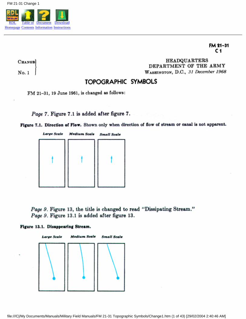
CHANGE 1, 31 DECEMBER 1968
CHAPTER 1 - INTRODUCTION
1 - Purpose
2 - Scope
3 - References
4 - Symbols and abbreviations
5 - Use of special symbols
6 - Scales of topographic maps
7 - Topographic maps
FM 21-31 Table of Contents
file:///C|/My Documents/Manuals/Military Field Manuals/FM 21-31 Topographic Symbols/toc.htm (1 of 3) [29/02/2004 2:39:17 AM]
CHAPTER 2 - TOPOGRAPHIC SYMBOLS
8 - Scope
9 - Drainage features
10 - Relief features
11 - Vegetation features
12 - Coastal hydrography
13 - Roads in the United States on large- and medium-scale maps
14 - Roads in foreign areas on large- and medium-scale maps
15 - Roads on small-scale maps
16 - Related road features
17 - Railroads
18 - Features related to communications
19 - Buildings and populated places on large-scale maps
20 - Buildings and populated places on medium- and small-scale maps
21 - Industrial and public works
22 - Control points and elevations
23 - Boundaries
CHAPTER 3 - TOPOGRAPHIC ABBREVIATIONS
24 - List of abbreviations
25 - Application
FM 21-31 Table of Contents
file:///C|/My Documents/Manuals/Military Field Manuals/FM 21-31 Topographic Symbols/toc.htm (2 of 3) [29/02/2004 2:39:17 AM]
CHAPTER 4 - MARGINAL INFORMATION
26 - Scope
27 - Map identification
28 - Other marginal data
APPENDIX I - REFERENCES
APPENDIX II - TOPOGRAPHIC ABBREVIATIONS
APPENDIX III - CHARTS
AUTHORIZATION LETTER
*This manual supersedes FM 21-31, 4 January 1952.
FM 21-31 Table of Contents
file:///C|/My Documents/Manuals/Military Field Manuals/FM 21-31 Topographic Symbols/toc.htm (3 of 3) [29/02/2004 2:39:17 AM]
RDLHomepage
Table ofContents
DocumentInformation
DownloadInstructions
CHAPTER 1
INTRODUCTION
1. Purpose
This manual describes the topographic symbols and abbreviations authorized for use by all echelons inthe interpretation of military maps, overlays, and related features and activities.
2. Scope
This manual is divided into four chapters.
a. Chapter 1 contains general information on the use of topographic symbols, gives the basic scales fortopographic maps, defines topographic maps, and discusses map detail, map accuracy, and map colors.
b. Chapter 2 gives examples and illustrations of topographic symbols arranged by categories, such asdrainage features, relief features, and roads.
c. Chapter 3 gives topographic abbreviations, their scope and application.
d. Chapter 4 discusses marginal information.
3. References
Appendix I is a list of publications which give detailed information on maps and mapping, foreignconventional signs and symbols, reference data for the various services, transportation and signalfacilities, and abbreviations for administrative and electrically transmitted messages.
4. Symbols and Abbreviations
a. Some of the symbols appearing on published maps may not agree entirely with those shown in thismanual, since it is necessary to devise or modify symbols to portray conditions or features which areunique to the area being mapped. Consequently, before any map is used, the symbol legend appearing inthe margin should be carefully studied.
b. The symbols and abbreviations given in this manual are the result of standardization proceedings andare in general agreement with those employed by the British Army, the Canadian Army, the AeronauticalChart and Information Service of the U.S. Air Force, the Hydrographic Office of the U.S. Navy, the U.S.Coast and Geodetic Survey, the U.S. Forest Service, the U.S. Geological Survey, and the TennesseeValley Authority.
FM 21-31 Chptr 1 Introduction
file:///C|/My Documents/Manuals/Military Field Manuals/FM 21-31 Topographic Symbols/Ch1.htm (1 of 4) [29/02/2004 2:41:35 AM]
c. Department of the Army units engaged in map making will be guided by AR 117-5, by TM 5-230 sofar as the symbols given as examples do not conflict with those given here, and by the specificationscontained in technical publications prepared under the direction of the Chief of Engineers.
d. Abbreviations given in this manual are for topographic use only and in some instances conflict withthose given in AR 320-50, which are authorized for use in military records, publications, correspondence,messages, and in field work. In accordance with AR 320-50, abbreviations will not be used if uncertaintymay result.
e. The information contained herein is applicable without modification to both nuclear and nonnuclearwarfare.
5. Use of Special Symbols
Where no symbol is prescribed for a specialized local feature, the map maker is authorized to use aspecial symbol, providing--
a. There is no conflict with symbols shown in this manual.
b. Any special symbol used is explained either in the legend of the map or by appropriate labeling withinthe body of the map, so that no uncertainty may result.
6. Scales of Topographic Maps
a. Maps fall into the following general scale categories:
Small scale . . . . . . . 1:600,000 and smaller.Medium scale . . . . . Larger than 1:600,000 but smaller than 1:75,000.Large scale . . . . . . . 1:75,000 and larger.
b. Standard scales for Department of the Army topographic maps are 1:1,000,000, 1:250, 000, 1:100,000,1:50,000, and 1:25,000. Military city maps normally are published at the scale of 1:12,500. Photomapsnormally are published at 1:25,000. General maps at scales smaller than 1:1,000,000 are issued forspecial purposes.
c. Depending upon the availability of mapping information and the importance of the area, the scale of1:500,000 is sometimes substituted for 1:250,000.
d. All of the above types and scales of maps will not necessarily be available for a particular area. Theirissue will be governed by military and logistic considerations.
e. Maps with scales different from those given above occasionally will be encountered. Usually, they areforeign military maps. The most common examples are 1:62,500 or 1:63, 360 in place of 1:50,000;1:125,000 in place of 1:100,000; and 1:253,440 in place of 1:250,000, In the United States, nonmilitarygovernmental mapping agencies may use other scales such as 1:24,000 or 1:31,680 in place of 1:25,000;and 1:48,000 or 1:62,500 in place of 1:50,000.
7. Topographic Maps
a. Introduction. A topographic map is a graphic representation to scale, horizontal and vertical, of someportion of the earth's surface, systematically plotted on a plane surface. The ideal situation would be
FM 21-31 Chptr 1 Introduction
file:///C|/My Documents/Manuals/Military Field Manuals/FM 21-31 Topographic Symbols/Ch1.htm (2 of 4) [29/02/2004 2:41:35 AM]
realized if every feature on the portion of the earth being mapped could be shown in its true shape,orientation, and proportion. Unfortunately, such a representation is impossible. This is evident when oneconsiders that on a map at the scale of 1:50,000, a square mile must be condensed into a small squareapproximately 1.27 by 1.27 inches. If every feature were plotted true to scale, the resulting map would beimpossible to read, for many items would be drawn so minutely as to be unrecognizable even with amagnifying glass. For a map to be intelligible, features must be indicated by symbols. Many of thesemust necessarily be exaggerated in size for legibility. For example, on a map at the scale of 1:50,000 theprescribed symbol for a small house covers an area corresponding to about 85 feet square, the scaledwidth of a road measures about 95 feet; the symbol for a single-track railroad occupies a widthequivalent to about 165 feet on the ground. Consequently, only the landmarks and important features ofan area can be shown. Those shown on a map represent the characteristic pattern of the area and areusually those most readily recognized in the field.
b. Map Detail. Map detail represents ground features as they existed at the date of map compilation orlatest revision. Since man is continually building, demolishing, and changing ground features, the detailappearing on a map may not exactly match that appearing on the ground. This is especially true indeveloped areas. The amount of detail shown on a map increases with its scale. A map attempts to showthe maximum of detail without impairing legibility. In areas of heavy cultural density, many of the lessimportant items must be omitted. In areas of sparse density, fewer items are omitted. When deletions arenecessary because of the density of detail, care is taken to retain the general pattern of the features in thearea. For example, where all buildings of a group cannot be shown, those retained portray the generalpattern of the group without exaggerating the area covered. Similarly, where numerous ditches, streams,levees, and the like exist, the less important are omitted and the more important are retained to show thecharacteristic pattern of the features in the area.
c. Symbols. So far as is practicable, a mapped feature is shown by the same symbol on maps of differentscales, but certain modifications and departures are necessary because of varying map uses and scales.Normally, symbols resemble the features they represent. The center and the orientation of a symbolusually correspond to the true center and orientation of the feature represented. All line features such asroads, railroads, streams, power lines, and similar features retain, within the limitations of scale, thevariations of alinement which actually exist. Along such features as roads, the locations of buildings andother features are necessarily displaced because of the exaggerated size of the symbols. Reference to thepositions of such features must be made with caution.
d. Accuracy of Maps. On a map of 1:1,000, 000, a sixteenth of an inch represents approximately 1 mile;on a map of 1:250,000, a quarter of an inch represents approximately 1 mile. It is apparent, then, that onsuch maps it is impossible to obtain the precise accuracy in plotting possible on large-scale maps. Smalland medium-scale maps normally are compiled from the best available larger-scale maps. Since thesesources vary in reliability, the map user should study the coverage diagram shown in the margin of themap to determine the general reliability of the map. On most large-scale maps of areas within thecontinental limits of the United States, 90 percent of all features shown are within 1/50 inch of their truegeographic positions. The remaining 10 percent are within 1/20 inch. Ninety percent of the contours areaccurate within one-half of the basic contour interval, and 90 percent of the spot heights (elevations ofparticular locations) are accurate within one-fourth of the contour interval. In compiling large-scale mapscovering foreign areas, it is not always possible to achieve the high standards of accuracy obtainable onmaps of the United States. The accuracy standards of such maps usually may be determined from themarginal coverage diagram.
FM 21-31 Chptr 1 Introduction
file:///C|/My Documents/Manuals/Military Field Manuals/FM 21-31 Topographic Symbols/Ch1.htm (3 of 4) [29/02/2004 2:41:35 AM]

e. Map Colors. Topographic symbols usually appear in characteristic colors: black for cultural(man-made) features other than roads, blue for water features, brown or gray for relief features, green forvegetation, and red for road classifications. Modifications of these colors occasionally are used toportray unique circumstances. Consequently, the symbol legend and other marginal information shouldbe carefully studied before using any map.
FM 21-31 Chptr 1 Introduction
file:///C|/My Documents/Manuals/Military Field Manuals/FM 21-31 Topographic Symbols/Ch1.htm (4 of 4) [29/02/2004 2:41:35 AM]
RDLHomepage
Table ofContents
DocumentInformation
DownloadInstructions
FM 21-31 Change 1
file:///C|/My Documents/Manuals/Military Field Manuals/FM 21-31 Topographic Symbols/Change1.htm (1 of 43) [29/02/2004 2:40:46 AM]
FM 21-31 Change 1
file:///C|/My Documents/Manuals/Military Field Manuals/FM 21-31 Topographic Symbols/Change1.htm (2 of 43) [29/02/2004 2:40:46 AM]
FM 21-31 Change 1
file:///C|/My Documents/Manuals/Military Field Manuals/FM 21-31 Topographic Symbols/Change1.htm (3 of 43) [29/02/2004 2:40:46 AM]
FM 21-31 Change 1
file:///C|/My Documents/Manuals/Military Field Manuals/FM 21-31 Topographic Symbols/Change1.htm (4 of 43) [29/02/2004 2:40:46 AM]
FM 21-31 Change 1
file:///C|/My Documents/Manuals/Military Field Manuals/FM 21-31 Topographic Symbols/Change1.htm (5 of 43) [29/02/2004 2:40:46 AM]
FM 21-31 Change 1
file:///C|/My Documents/Manuals/Military Field Manuals/FM 21-31 Topographic Symbols/Change1.htm (6 of 43) [29/02/2004 2:40:46 AM]
FM 21-31 Change 1
file:///C|/My Documents/Manuals/Military Field Manuals/FM 21-31 Topographic Symbols/Change1.htm (7 of 43) [29/02/2004 2:40:46 AM]
FM 21-31 Change 1
file:///C|/My Documents/Manuals/Military Field Manuals/FM 21-31 Topographic Symbols/Change1.htm (8 of 43) [29/02/2004 2:40:46 AM]
FM 21-31 Change 1
file:///C|/My Documents/Manuals/Military Field Manuals/FM 21-31 Topographic Symbols/Change1.htm (9 of 43) [29/02/2004 2:40:46 AM]
FM 21-31 Change 1
file:///C|/My Documents/Manuals/Military Field Manuals/FM 21-31 Topographic Symbols/Change1.htm (10 of 43) [29/02/2004 2:40:46 AM]
FM 21-31 Change 1
file:///C|/My Documents/Manuals/Military Field Manuals/FM 21-31 Topographic Symbols/Change1.htm (11 of 43) [29/02/2004 2:40:47 AM]
FM 21-31 Change 1
file:///C|/My Documents/Manuals/Military Field Manuals/FM 21-31 Topographic Symbols/Change1.htm (12 of 43) [29/02/2004 2:40:47 AM]
FM 21-31 Change 1
file:///C|/My Documents/Manuals/Military Field Manuals/FM 21-31 Topographic Symbols/Change1.htm (13 of 43) [29/02/2004 2:40:47 AM]
FM 21-31 Change 1
file:///C|/My Documents/Manuals/Military Field Manuals/FM 21-31 Topographic Symbols/Change1.htm (14 of 43) [29/02/2004 2:40:47 AM]
FM 21-31 Change 1
file:///C|/My Documents/Manuals/Military Field Manuals/FM 21-31 Topographic Symbols/Change1.htm (15 of 43) [29/02/2004 2:40:47 AM]
FM 21-31 Change 1
file:///C|/My Documents/Manuals/Military Field Manuals/FM 21-31 Topographic Symbols/Change1.htm (16 of 43) [29/02/2004 2:40:47 AM]
FM 21-31 Change 1
file:///C|/My Documents/Manuals/Military Field Manuals/FM 21-31 Topographic Symbols/Change1.htm (17 of 43) [29/02/2004 2:40:47 AM]
FM 21-31 Change 1
file:///C|/My Documents/Manuals/Military Field Manuals/FM 21-31 Topographic Symbols/Change1.htm (18 of 43) [29/02/2004 2:40:47 AM]
FM 21-31 Change 1
file:///C|/My Documents/Manuals/Military Field Manuals/FM 21-31 Topographic Symbols/Change1.htm (19 of 43) [29/02/2004 2:40:47 AM]
FM 21-31 Change 1
file:///C|/My Documents/Manuals/Military Field Manuals/FM 21-31 Topographic Symbols/Change1.htm (20 of 43) [29/02/2004 2:40:47 AM]
FM 21-31 Change 1
file:///C|/My Documents/Manuals/Military Field Manuals/FM 21-31 Topographic Symbols/Change1.htm (21 of 43) [29/02/2004 2:40:47 AM]
FM 21-31 Change 1
file:///C|/My Documents/Manuals/Military Field Manuals/FM 21-31 Topographic Symbols/Change1.htm (22 of 43) [29/02/2004 2:40:47 AM]
FM 21-31 Change 1
file:///C|/My Documents/Manuals/Military Field Manuals/FM 21-31 Topographic Symbols/Change1.htm (23 of 43) [29/02/2004 2:40:47 AM]
FM 21-31 Change 1
file:///C|/My Documents/Manuals/Military Field Manuals/FM 21-31 Topographic Symbols/Change1.htm (24 of 43) [29/02/2004 2:40:47 AM]

FM 21-31 Change 1
file:///C|/My Documents/Manuals/Military Field Manuals/FM 21-31 Topographic Symbols/Change1.htm (25 of 43) [29/02/2004 2:40:47 AM]
FM 21-31 Change 1
file:///C|/My Documents/Manuals/Military Field Manuals/FM 21-31 Topographic Symbols/Change1.htm (26 of 43) [29/02/2004 2:40:47 AM]
FM 21-31 Change 1
file:///C|/My Documents/Manuals/Military Field Manuals/FM 21-31 Topographic Symbols/Change1.htm (27 of 43) [29/02/2004 2:40:47 AM]
FM 21-31 Change 1
file:///C|/My Documents/Manuals/Military Field Manuals/FM 21-31 Topographic Symbols/Change1.htm (28 of 43) [29/02/2004 2:40:47 AM]
FM 21-31 Change 1
file:///C|/My Documents/Manuals/Military Field Manuals/FM 21-31 Topographic Symbols/Change1.htm (29 of 43) [29/02/2004 2:40:47 AM]
FM 21-31 Change 1
file:///C|/My Documents/Manuals/Military Field Manuals/FM 21-31 Topographic Symbols/Change1.htm (30 of 43) [29/02/2004 2:40:47 AM]
FM 21-31 Change 1
file:///C|/My Documents/Manuals/Military Field Manuals/FM 21-31 Topographic Symbols/Change1.htm (31 of 43) [29/02/2004 2:40:47 AM]
FM 21-31 Change 1
file:///C|/My Documents/Manuals/Military Field Manuals/FM 21-31 Topographic Symbols/Change1.htm (32 of 43) [29/02/2004 2:40:47 AM]
FM 21-31 Change 1
file:///C|/My Documents/Manuals/Military Field Manuals/FM 21-31 Topographic Symbols/Change1.htm (33 of 43) [29/02/2004 2:40:47 AM]
FM 21-31 Change 1
file:///C|/My Documents/Manuals/Military Field Manuals/FM 21-31 Topographic Symbols/Change1.htm (34 of 43) [29/02/2004 2:40:47 AM]
FM 21-31 Change 1
file:///C|/My Documents/Manuals/Military Field Manuals/FM 21-31 Topographic Symbols/Change1.htm (35 of 43) [29/02/2004 2:40:47 AM]
FM 21-31 Change 1
file:///C|/My Documents/Manuals/Military Field Manuals/FM 21-31 Topographic Symbols/Change1.htm (36 of 43) [29/02/2004 2:40:47 AM]
FM 21-31 Change 1
file:///C|/My Documents/Manuals/Military Field Manuals/FM 21-31 Topographic Symbols/Change1.htm (37 of 43) [29/02/2004 2:40:47 AM]
FM 21-31 Change 1
file:///C|/My Documents/Manuals/Military Field Manuals/FM 21-31 Topographic Symbols/Change1.htm (38 of 43) [29/02/2004 2:40:47 AM]
FM 21-31 Change 1
file:///C|/My Documents/Manuals/Military Field Manuals/FM 21-31 Topographic Symbols/Change1.htm (39 of 43) [29/02/2004 2:40:47 AM]
FM 21-31 Change 1
file:///C|/My Documents/Manuals/Military Field Manuals/FM 21-31 Topographic Symbols/Change1.htm (40 of 43) [29/02/2004 2:40:47 AM]
FM 21-31 Change 1
file:///C|/My Documents/Manuals/Military Field Manuals/FM 21-31 Topographic Symbols/Change1.htm (41 of 43) [29/02/2004 2:40:47 AM]
FM 21-31 Change 1
file:///C|/My Documents/Manuals/Military Field Manuals/FM 21-31 Topographic Symbols/Change1.htm (42 of 43) [29/02/2004 2:40:47 AM]
FM 21-31 Change 1
file:///C|/My Documents/Manuals/Military Field Manuals/FM 21-31 Topographic Symbols/Change1.htm (43 of 43) [29/02/2004 2:40:47 AM]
RDLHomepage
Table ofContents
DocumentInformation
DownloadInstructions
CHAPTER 2
TOPOGRAPHIC SYMBOLS
8. Scope
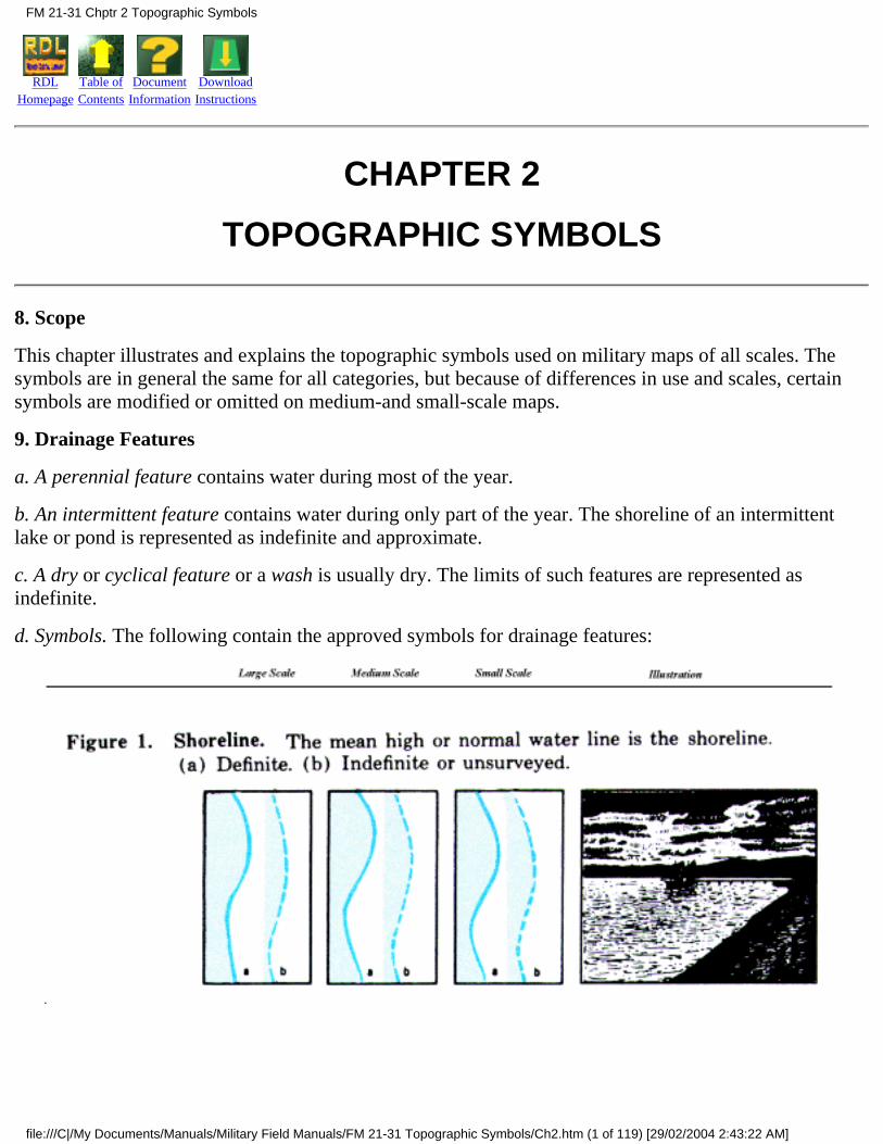
This chapter illustrates and explains the topographic symbols used on military maps of all scales. Thesymbols are in general the same for all categories, but because of differences in use and scales, certainsymbols are modified or omitted on medium-and small-scale maps.
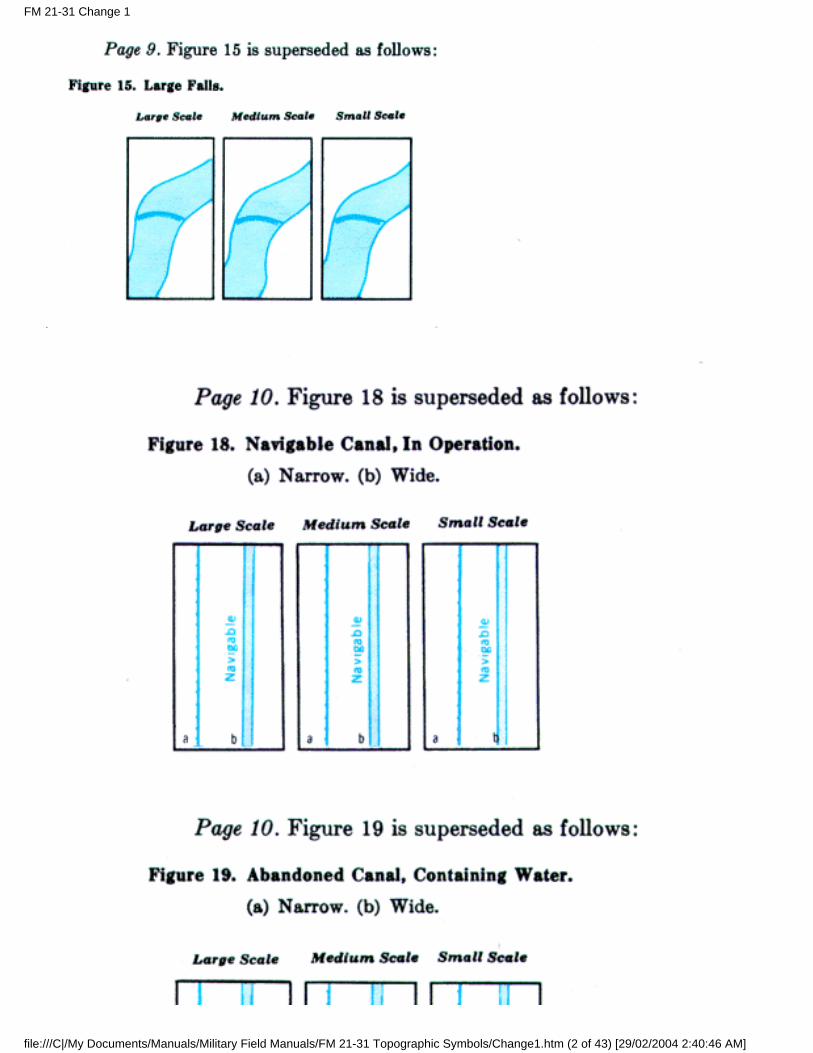
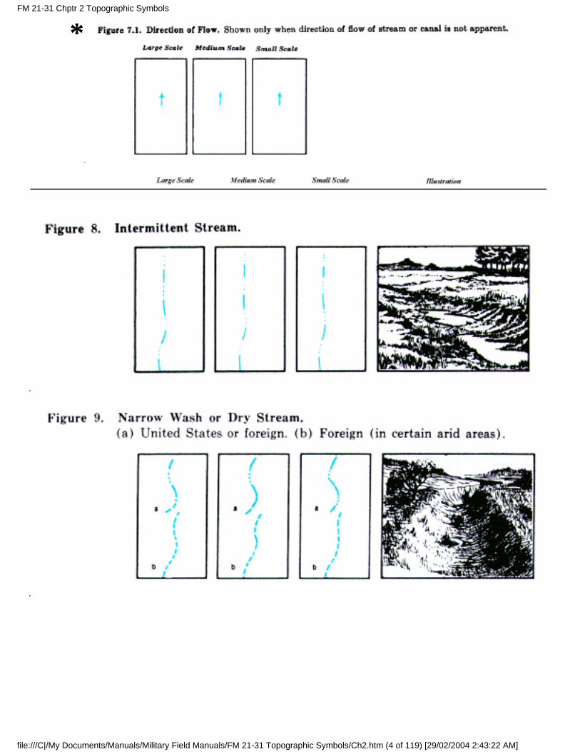
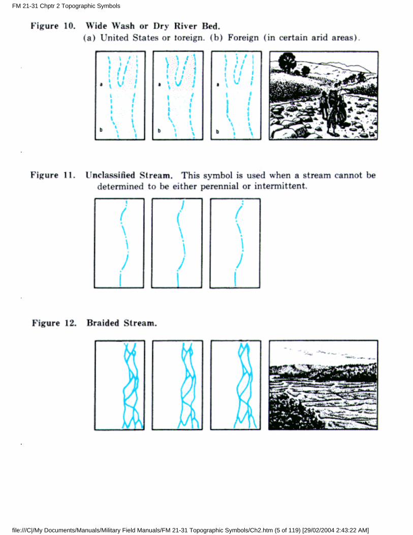
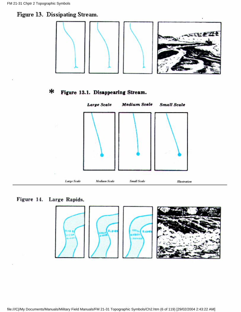
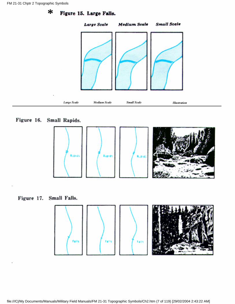
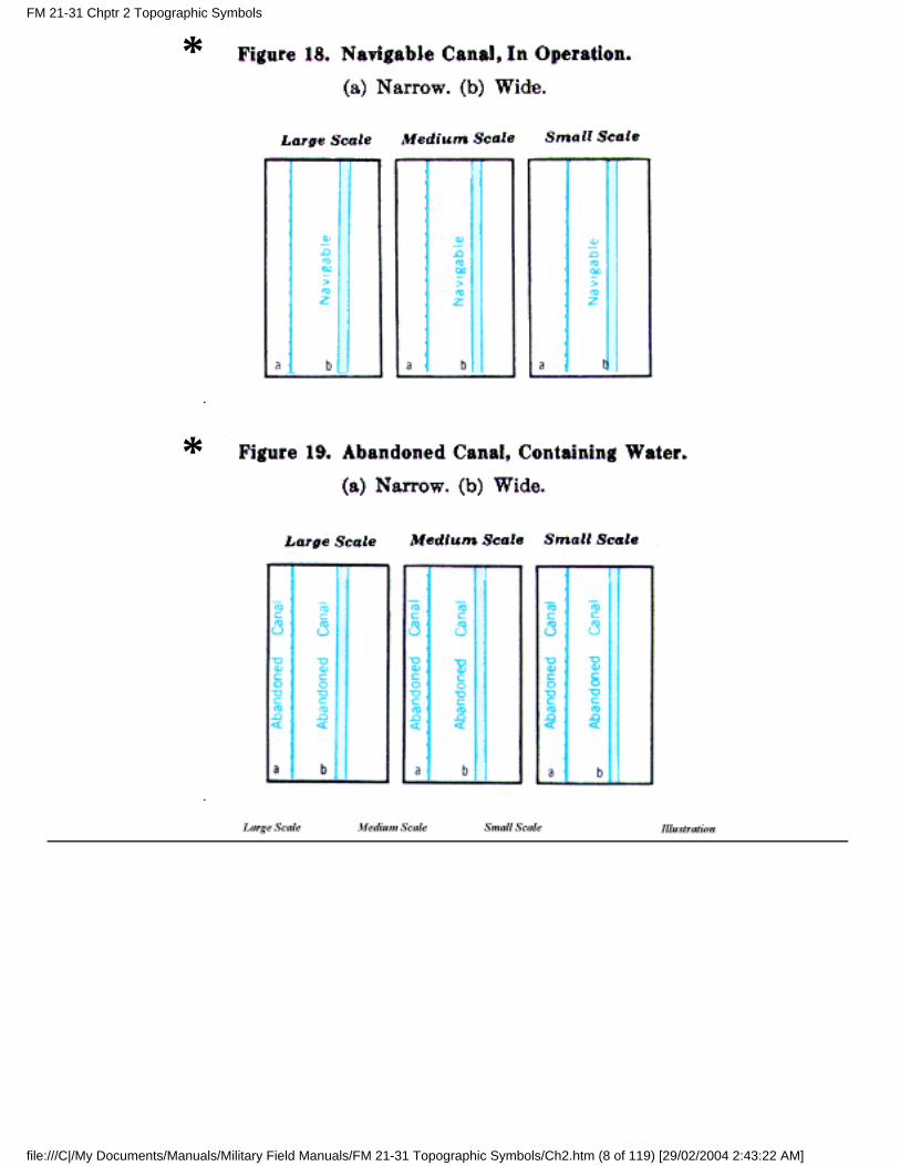
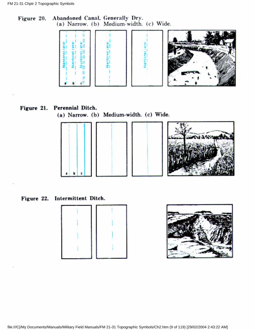
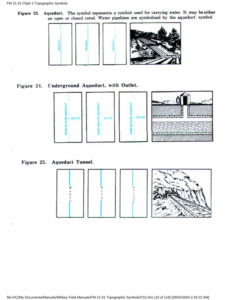
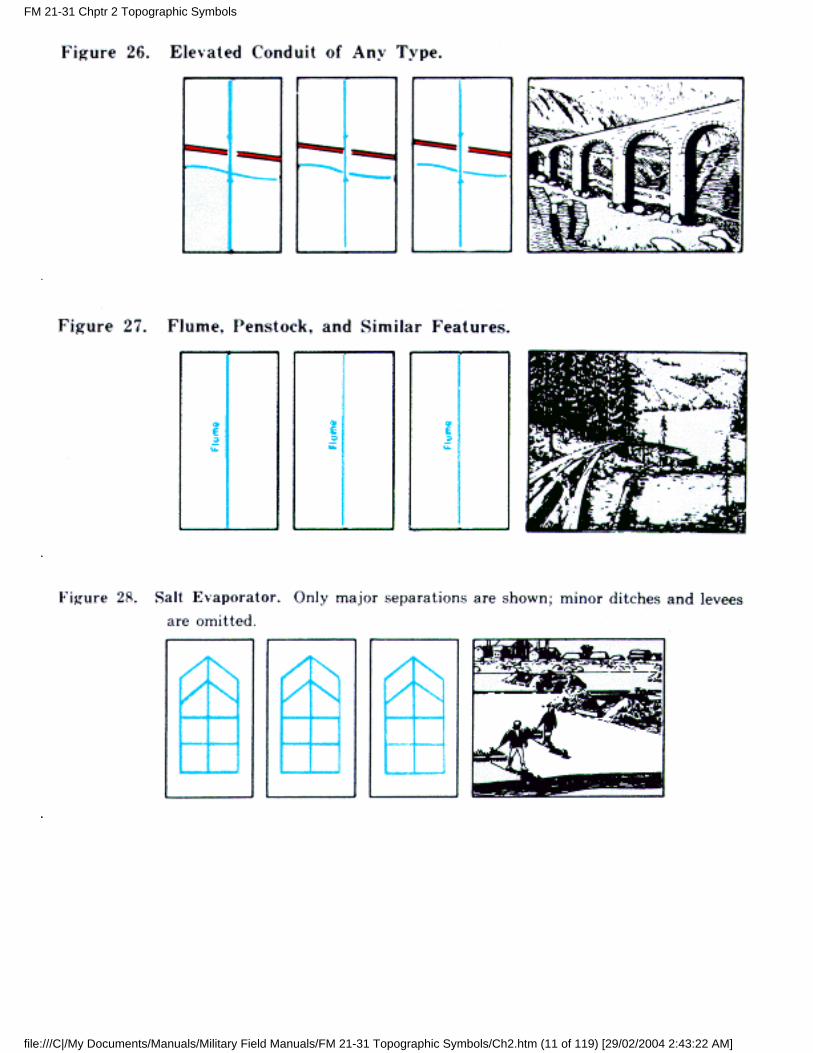
9. Drainage Features
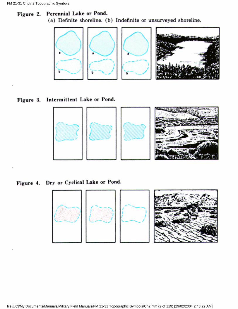
a. A perennial feature contains water during most of the year.
b. An intermittent feature contains water during only part of the year. The shoreline of an intermittentlake or pond is represented as indefinite and approximate.
c. A dry or cyclical feature or a wash is usually dry. The limits of such features are represented asindefinite.
d. Symbols. The following contain the approved symbols for drainage features:
FM 21-31 Chptr 2 Topographic Symbols
file:///C|/My Documents/Manuals/Military Field Manuals/FM 21-31 Topographic Symbols/Ch2.htm (1 of 119) [29/02/2004 2:43:22 AM]
FM 21-31 Chptr 2 Topographic Symbols
file:///C|/My Documents/Manuals/Military Field Manuals/FM 21-31 Topographic Symbols/Ch2.htm (2 of 119) [29/02/2004 2:43:22 AM]
FM 21-31 Chptr 2 Topographic Symbols
file:///C|/My Documents/Manuals/Military Field Manuals/FM 21-31 Topographic Symbols/Ch2.htm (3 of 119) [29/02/2004 2:43:22 AM]
*FM 21-31 Chptr 2 Topographic Symbols
file:///C|/My Documents/Manuals/Military Field Manuals/FM 21-31 Topographic Symbols/Ch2.htm (4 of 119) [29/02/2004 2:43:22 AM]
FM 21-31 Chptr 2 Topographic Symbols
file:///C|/My Documents/Manuals/Military Field Manuals/FM 21-31 Topographic Symbols/Ch2.htm (5 of 119) [29/02/2004 2:43:22 AM]
*
FM 21-31 Chptr 2 Topographic Symbols
file:///C|/My Documents/Manuals/Military Field Manuals/FM 21-31 Topographic Symbols/Ch2.htm (6 of 119) [29/02/2004 2:43:22 AM]
*FM 21-31 Chptr 2 Topographic Symbols
file:///C|/My Documents/Manuals/Military Field Manuals/FM 21-31 Topographic Symbols/Ch2.htm (7 of 119) [29/02/2004 2:43:22 AM]
*
*
FM 21-31 Chptr 2 Topographic Symbols
file:///C|/My Documents/Manuals/Military Field Manuals/FM 21-31 Topographic Symbols/Ch2.htm (8 of 119) [29/02/2004 2:43:22 AM]
FM 21-31 Chptr 2 Topographic Symbols
file:///C|/My Documents/Manuals/Military Field Manuals/FM 21-31 Topographic Symbols/Ch2.htm (9 of 119) [29/02/2004 2:43:22 AM]
FM 21-31 Chptr 2 Topographic Symbols
file:///C|/My Documents/Manuals/Military Field Manuals/FM 21-31 Topographic Symbols/Ch2.htm (10 of 119) [29/02/2004 2:43:22 AM]
FM 21-31 Chptr 2 Topographic Symbols
file:///C|/My Documents/Manuals/Military Field Manuals/FM 21-31 Topographic Symbols/Ch2.htm (11 of 119) [29/02/2004 2:43:22 AM]
FM 21-31 Chptr 2 Topographic Symbols
file:///C|/My Documents/Manuals/Military Field Manuals/FM 21-31 Topographic Symbols/Ch2.htm (12 of 119) [29/02/2004 2:43:22 AM]
FM 21-31 Chptr 2 Topographic Symbols
file:///C|/My Documents/Manuals/Military Field Manuals/FM 21-31 Topographic Symbols/Ch2.htm (13 of 119) [29/02/2004 2:43:22 AM]
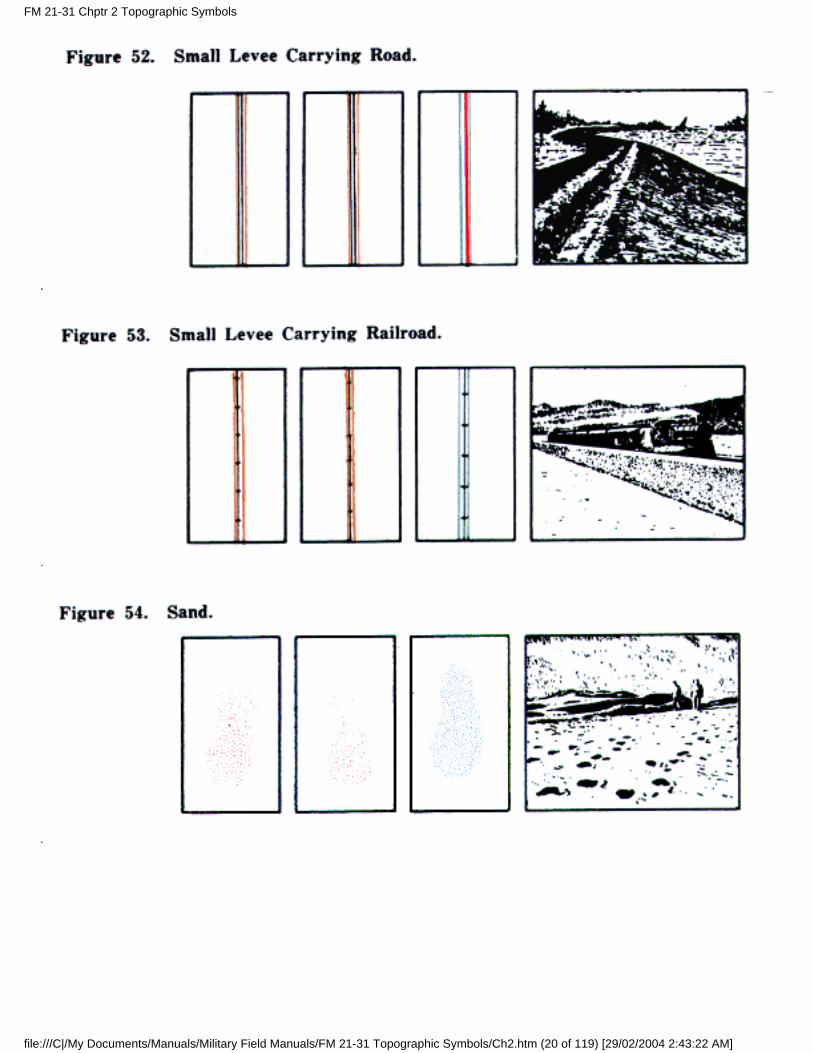
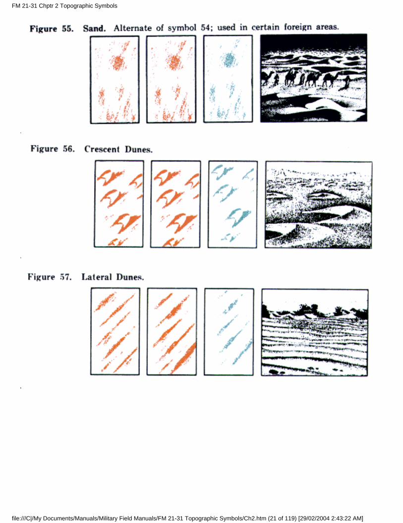
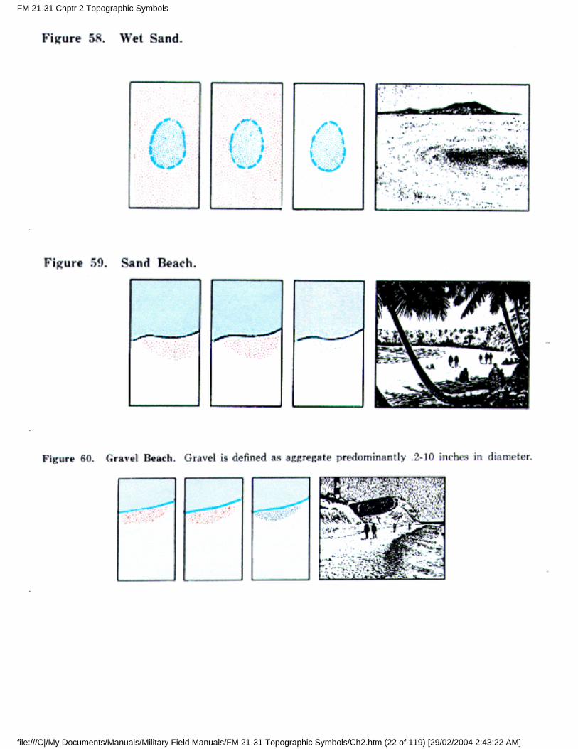
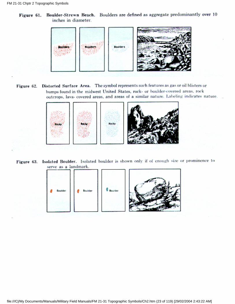
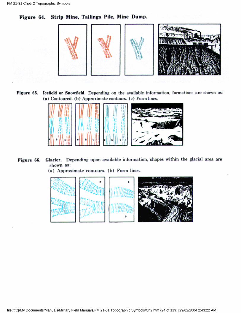
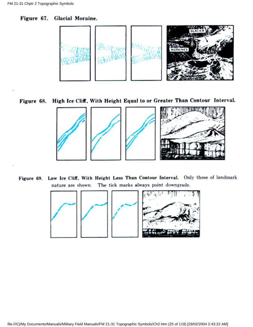
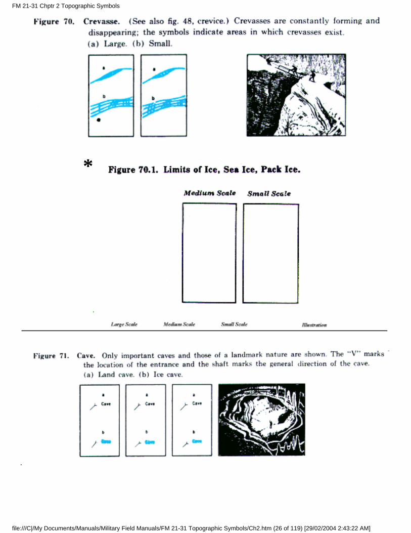
10. Relief Features
a. Methods of Showing Relief. Depending upon the accuracy of information, the shapes of the terrain areshown on a map by lines representing contours, approximate contours, and form lines. Any one or all ofthese methods may be used on a single map. On medium-and small-scale maps, significant relief featuresmay be shown by hachures when available data are insufficient to warrant the use of contours. On large-and medium-scale maps, the lines usually are printed in brown. Also, on medium-scale maps, hillshading usually is added over the brown lines, to print gray. This creates a three-dimensional effect andpermits a ready appreciation of the terrain, since the hills and ridges stand out much as they would on a
FM 21-31 Chptr 2 Topographic Symbols
file:///C|/My Documents/Manuals/Military Field Manuals/FM 21-31 Topographic Symbols/Ch2.htm (14 of 119) [29/02/2004 2:43:22 AM]
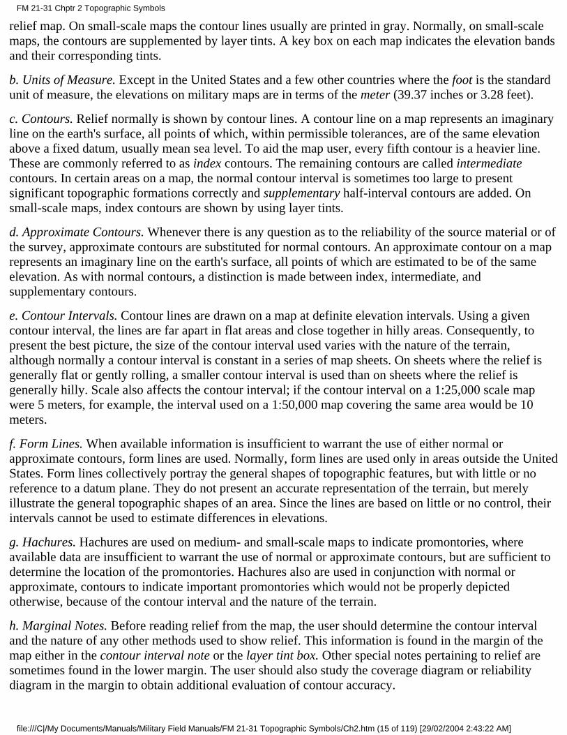
relief map. On small-scale maps the contour lines usually are printed in gray. Normally, on small-scalemaps, the contours are supplemented by layer tints. A key box on each map indicates the elevation bandsand their corresponding tints.
b. Units of Measure. Except in the United States and a few other countries where the foot is the standardunit of measure, the elevations on military maps are in terms of the meter (39.37 inches or 3.28 feet).
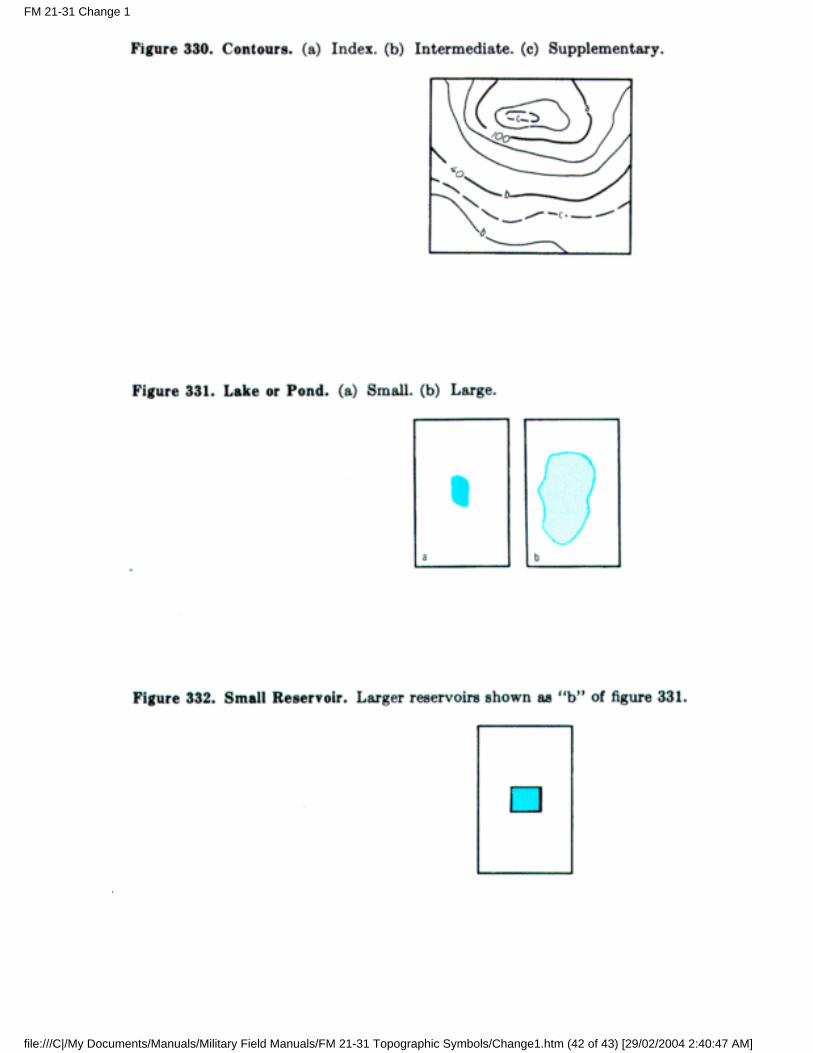
c. Contours. Relief normally is shown by contour lines. A contour line on a map represents an imaginaryline on the earth's surface, all points of which, within permissible tolerances, are of the same elevationabove a fixed datum, usually mean sea level. To aid the map user, every fifth contour is a heavier line.These are commonly referred to as index contours. The remaining contours are called intermediatecontours. In certain areas on a map, the normal contour interval is sometimes too large to presentsignificant topographic formations correctly and supplementary half-interval contours are added. Onsmall-scale maps, index contours are shown by using layer tints.
d. Approximate Contours. Whenever there is any question as to the reliability of the source material or ofthe survey, approximate contours are substituted for normal contours. An approximate contour on a maprepresents an imaginary line on the earth's surface, all points of which are estimated to be of the sameelevation. As with normal contours, a distinction is made between index, intermediate, andsupplementary contours.
e. Contour Intervals. Contour lines are drawn on a map at definite elevation intervals. Using a givencontour interval, the lines are far apart in flat areas and close together in hilly areas. Consequently, topresent the best picture, the size of the contour interval used varies with the nature of the terrain,although normally a contour interval is constant in a series of map sheets. On sheets where the relief isgenerally flat or gently rolling, a smaller contour interval is used than on sheets where the relief isgenerally hilly. Scale also affects the contour interval; if the contour interval on a 1:25,000 scale mapwere 5 meters, for example, the interval used on a 1:50,000 map covering the same area would be 10meters.
f. Form Lines. When available information is insufficient to warrant the use of either normal orapproximate contours, form lines are used. Normally, form lines are used only in areas outside the UnitedStates. Form lines collectively portray the general shapes of topographic features, but with little or noreference to a datum plane. They do not present an accurate representation of the terrain, but merelyillustrate the general topographic shapes of an area. Since the lines are based on little or no control, theirintervals cannot be used to estimate differences in elevations.
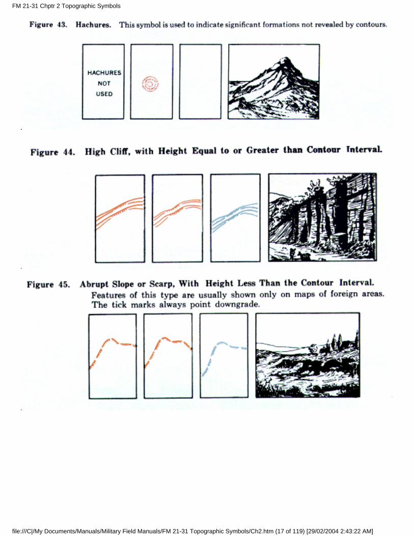
g. Hachures. Hachures are used on medium- and small-scale maps to indicate promontories, whereavailable data are insufficient to warrant the use of normal or approximate contours, but are sufficient todetermine the location of the promontories. Hachures also are used in conjunction with normal orapproximate, contours to indicate important promontories which would not be properly depictedotherwise, because of the contour interval and the nature of the terrain.
h. Marginal Notes. Before reading relief from the map, the user should determine the contour intervaland the nature of any other methods used to show relief. This information is found in the margin of themap either in the contour interval note or the layer tint box. Other special notes pertaining to relief aresometimes found in the lower margin. The user should also study the coverage diagram or reliabilitydiagram in the margin to obtain additional evaluation of contour accuracy.
FM 21-31 Chptr 2 Topographic Symbols
file:///C|/My Documents/Manuals/Military Field Manuals/FM 21-31 Topographic Symbols/Ch2.htm (15 of 119) [29/02/2004 2:43:22 AM]
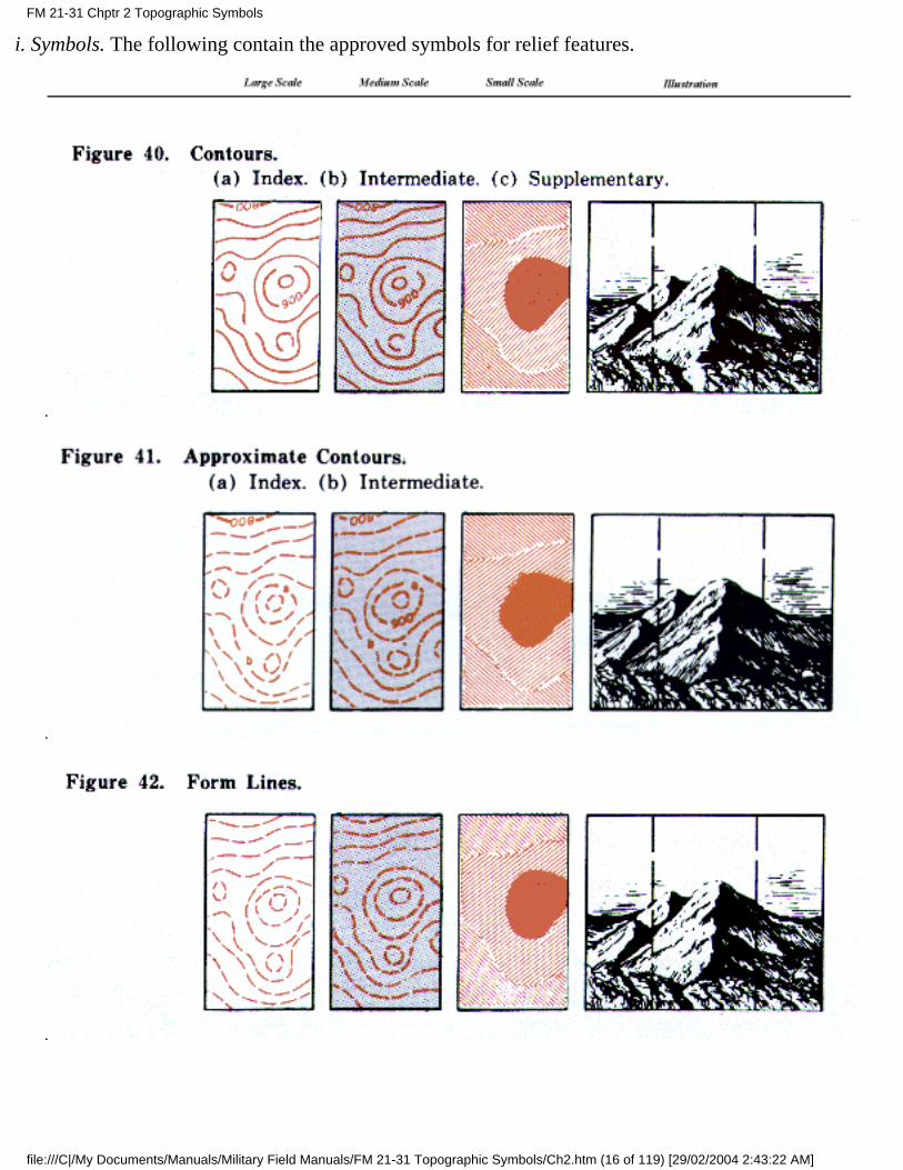
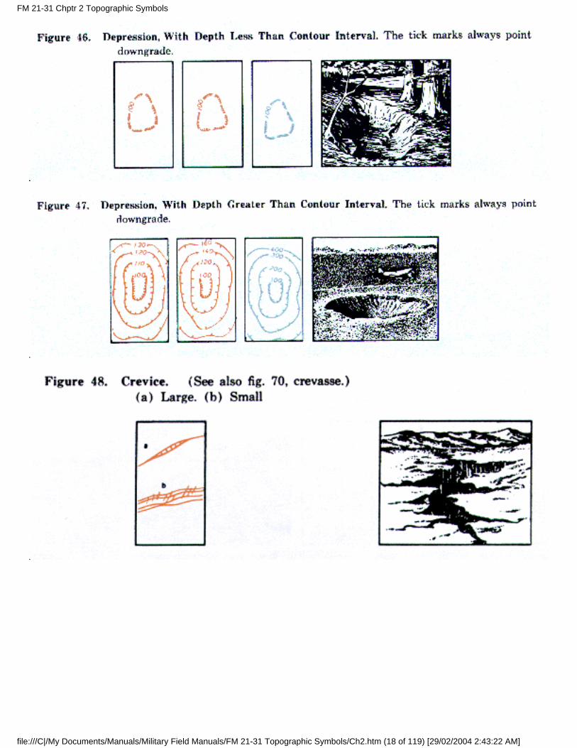
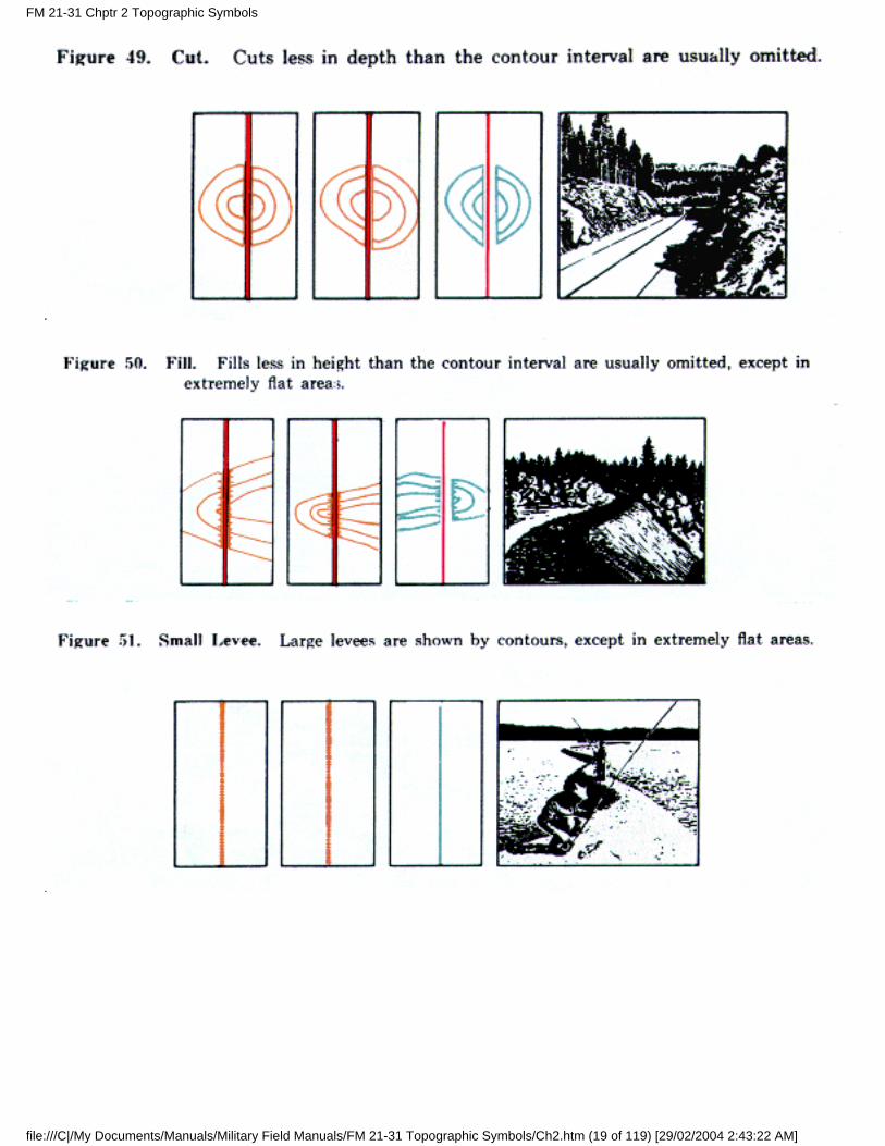
i. Symbols. The following contain the approved symbols for relief features.
FM 21-31 Chptr 2 Topographic Symbols
file:///C|/My Documents/Manuals/Military Field Manuals/FM 21-31 Topographic Symbols/Ch2.htm (16 of 119) [29/02/2004 2:43:22 AM]
FM 21-31 Chptr 2 Topographic Symbols
file:///C|/My Documents/Manuals/Military Field Manuals/FM 21-31 Topographic Symbols/Ch2.htm (17 of 119) [29/02/2004 2:43:22 AM]
FM 21-31 Chptr 2 Topographic Symbols
file:///C|/My Documents/Manuals/Military Field Manuals/FM 21-31 Topographic Symbols/Ch2.htm (18 of 119) [29/02/2004 2:43:22 AM]
FM 21-31 Chptr 2 Topographic Symbols
file:///C|/My Documents/Manuals/Military Field Manuals/FM 21-31 Topographic Symbols/Ch2.htm (19 of 119) [29/02/2004 2:43:22 AM]
FM 21-31 Chptr 2 Topographic Symbols
file:///C|/My Documents/Manuals/Military Field Manuals/FM 21-31 Topographic Symbols/Ch2.htm (20 of 119) [29/02/2004 2:43:22 AM]
FM 21-31 Chptr 2 Topographic Symbols
file:///C|/My Documents/Manuals/Military Field Manuals/FM 21-31 Topographic Symbols/Ch2.htm (21 of 119) [29/02/2004 2:43:22 AM]
FM 21-31 Chptr 2 Topographic Symbols
file:///C|/My Documents/Manuals/Military Field Manuals/FM 21-31 Topographic Symbols/Ch2.htm (22 of 119) [29/02/2004 2:43:22 AM]
FM 21-31 Chptr 2 Topographic Symbols
file:///C|/My Documents/Manuals/Military Field Manuals/FM 21-31 Topographic Symbols/Ch2.htm (23 of 119) [29/02/2004 2:43:22 AM]
FM 21-31 Chptr 2 Topographic Symbols
file:///C|/My Documents/Manuals/Military Field Manuals/FM 21-31 Topographic Symbols/Ch2.htm (24 of 119) [29/02/2004 2:43:22 AM]
FM 21-31 Chptr 2 Topographic Symbols
file:///C|/My Documents/Manuals/Military Field Manuals/FM 21-31 Topographic Symbols/Ch2.htm (25 of 119) [29/02/2004 2:43:22 AM]
*
FM 21-31 Chptr 2 Topographic Symbols
file:///C|/My Documents/Manuals/Military Field Manuals/FM 21-31 Topographic Symbols/Ch2.htm (26 of 119) [29/02/2004 2:43:22 AM]
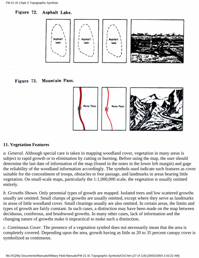
11. Vegetation Features
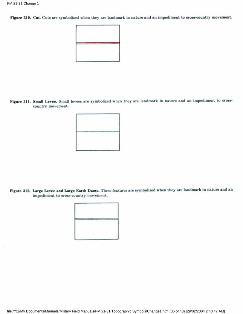
a. General. Although special care is taken in mapping woodland cover, vegetation in many areas issubject to rapid growth or to elimination by cutting or burning. Before using the map, the user shoulddetermine the last date of information of the map (found in the notes in the lower left margin) and gagethe reliability of the woodland information accordingly. The symbols used indicate such features as coversuitable for the concealment of troops, obstacles to free passage, and landmarks in areas bearing littlevegetation. On small-scale maps, particularly the 1:1,000,000 scale, the vegetation is usually omittedentirely.
b. Growths Shown. Only perennial types of growth are mapped. Isolated trees and low scattered growthsusually are omitted. Small clumps of growths are usually omitted, except where they serve as landmarksin areas of little woodland cover. Small clearings usually are also omitted. In certain areas, the limits andtypes of growth are fairly constant. In such cases, a distinction may have been made on the map betweendeciduous, coniferous, and brushwood growths. In many other cases, lack of information and thechanging nature of growths make it impractical to make such a distinction.
c. Continuous Cover. The presence of a vegetation symbol does not necessarily mean that the area iscompletely covered. Depending upon the area, growth having as little as 20 to 35 percent canopy cover issymbolized as continuous.
FM 21-31 Chptr 2 Topographic Symbols
file:///C|/My Documents/Manuals/Military Field Manuals/FM 21-31 Topographic Symbols/Ch2.htm (27 of 119) [29/02/2004 2:43:22 AM]
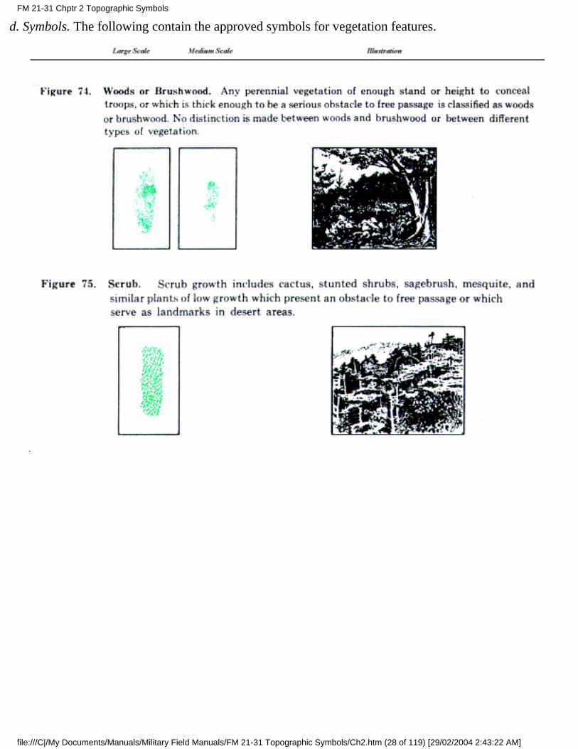
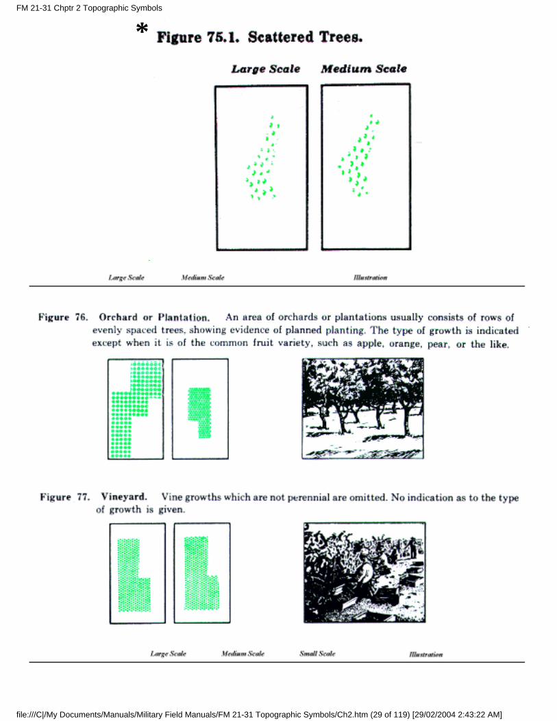
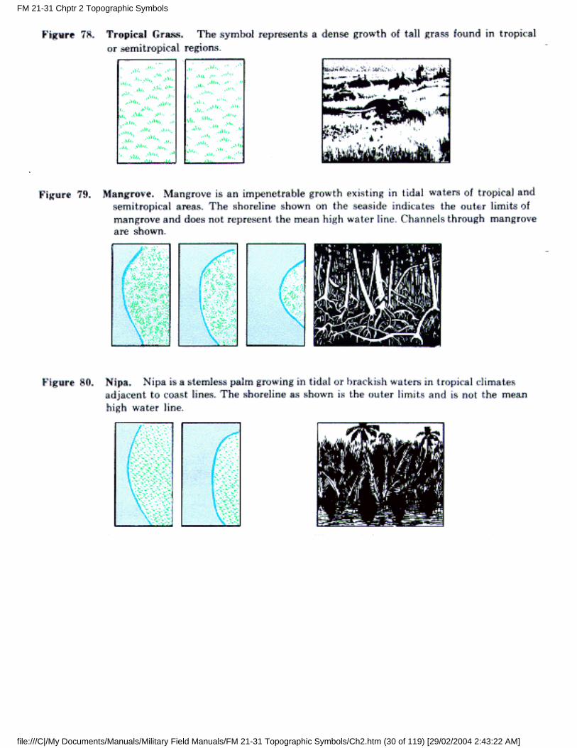
d. Symbols. The following contain the approved symbols for vegetation features.
FM 21-31 Chptr 2 Topographic Symbols
file:///C|/My Documents/Manuals/Military Field Manuals/FM 21-31 Topographic Symbols/Ch2.htm (28 of 119) [29/02/2004 2:43:22 AM]
*FM 21-31 Chptr 2 Topographic Symbols
file:///C|/My Documents/Manuals/Military Field Manuals/FM 21-31 Topographic Symbols/Ch2.htm (29 of 119) [29/02/2004 2:43:22 AM]
FM 21-31 Chptr 2 Topographic Symbols
file:///C|/My Documents/Manuals/Military Field Manuals/FM 21-31 Topographic Symbols/Ch2.htm (30 of 119) [29/02/2004 2:43:22 AM]
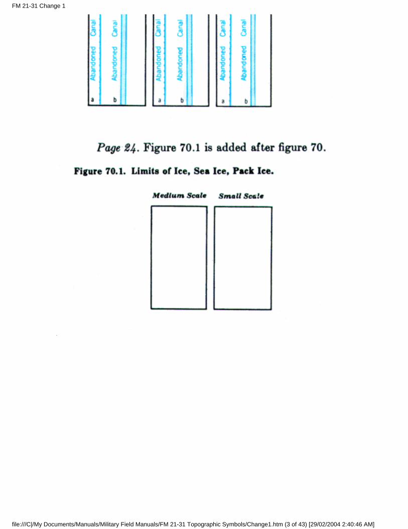
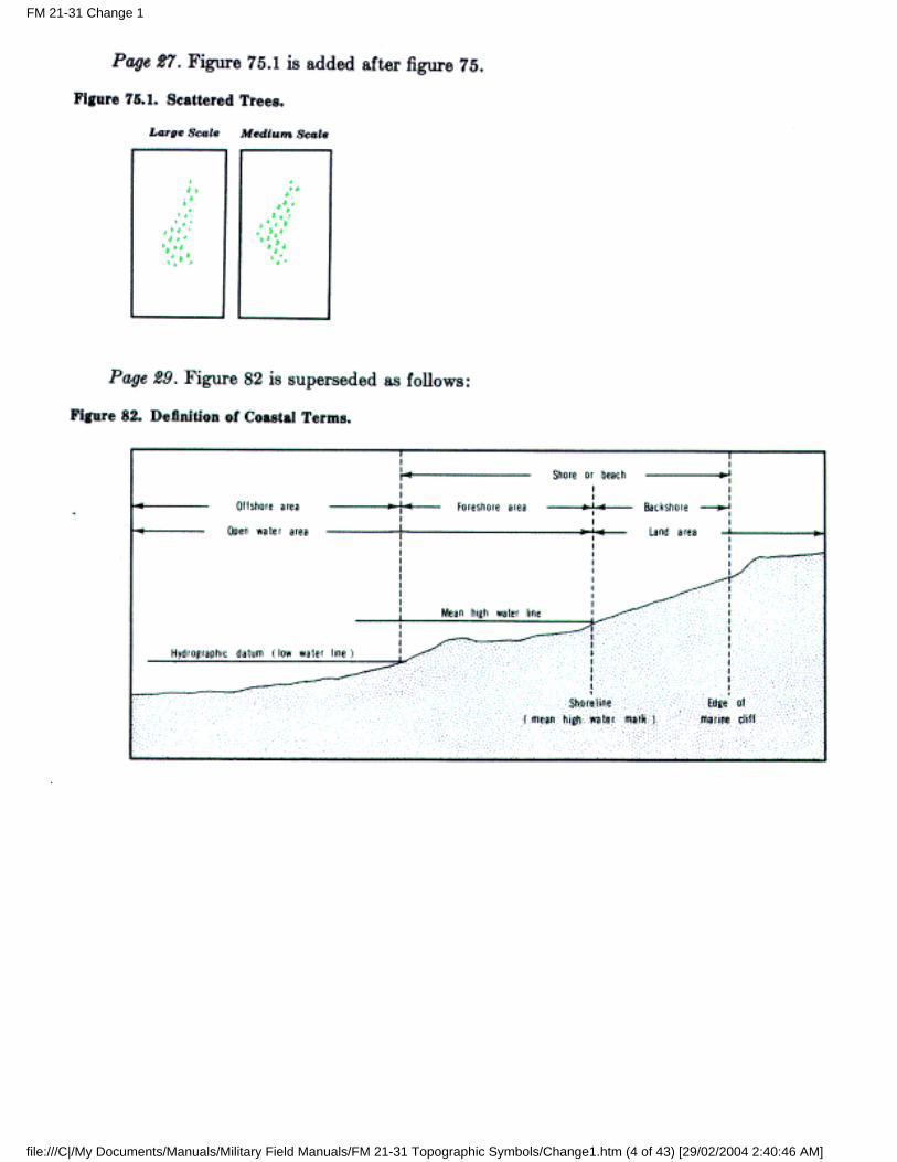
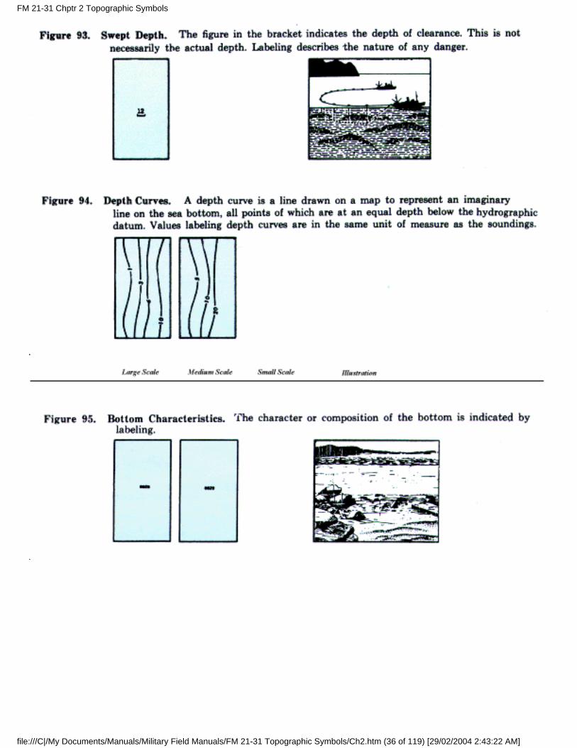
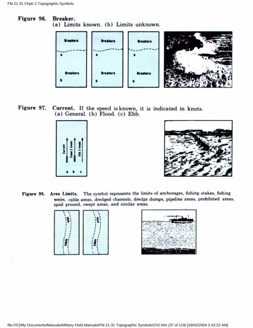
12. Coastal Hydrography
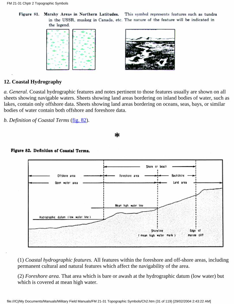
a. General. Coastal hydrographic features and notes pertinent to those features usually are shown on allsheets showing navigable waters. Sheets showing land areas bordering on inland bodies of water, such aslakes, contain only offshore data. Sheets showing land areas bordering on oceans, seas, bays, or similarbodies of water contain both offshore and foreshore data.
b. Definition of Coastal Terms (fig. 82).
*
(1) Coastal hydrographic features. All features within the foreshore and off-shore areas, includingpermanent cultural and natural features which affect the navigability of the area.
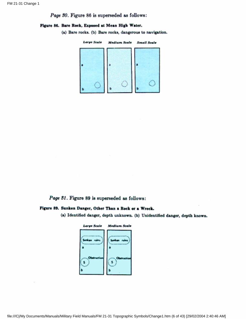
(2) Foreshore area. That area which is bare or awash at the hydrographic datum (low water) butwhich is covered at mean high water.
FM 21-31 Chptr 2 Topographic Symbols
file:///C|/My Documents/Manuals/Military Field Manuals/FM 21-31 Topographic Symbols/Ch2.htm (31 of 119) [29/02/2004 2:43:22 AM]
(3) Offshore area. That area which is covered at the hydrographic datum.
(4) Hydrographic datum. That stage of low tide to which depths are referred. This variessomewhat in different parts of the world.
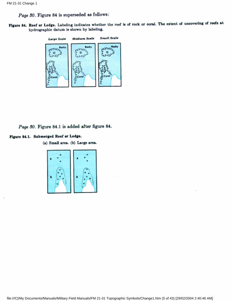
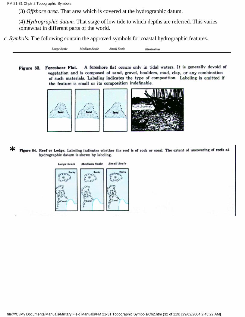
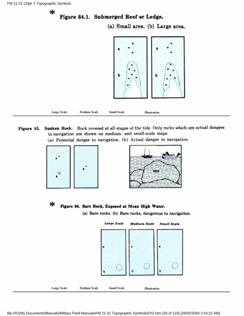
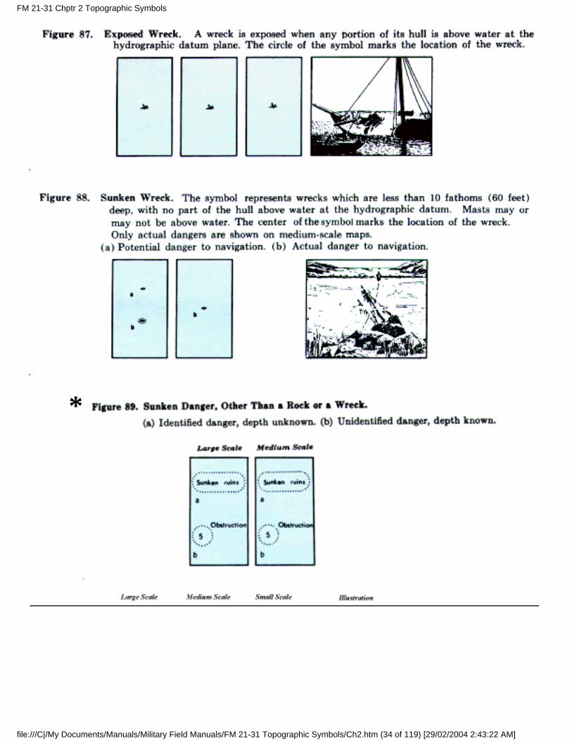
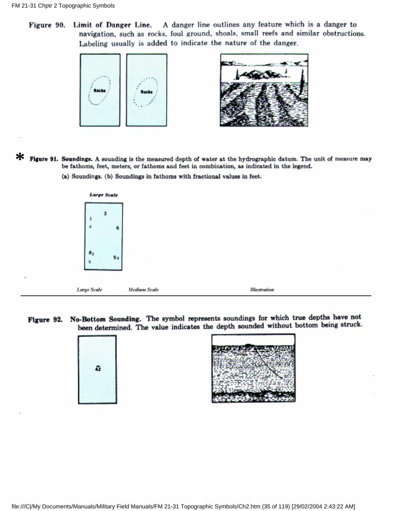
c. Symbols. The following contain the approved symbols for coastal hydrographic features.
*
FM 21-31 Chptr 2 Topographic Symbols
file:///C|/My Documents/Manuals/Military Field Manuals/FM 21-31 Topographic Symbols/Ch2.htm (32 of 119) [29/02/2004 2:43:22 AM]
*
*
FM 21-31 Chptr 2 Topographic Symbols
file:///C|/My Documents/Manuals/Military Field Manuals/FM 21-31 Topographic Symbols/Ch2.htm (33 of 119) [29/02/2004 2:43:22 AM]
*
FM 21-31 Chptr 2 Topographic Symbols
file:///C|/My Documents/Manuals/Military Field Manuals/FM 21-31 Topographic Symbols/Ch2.htm (34 of 119) [29/02/2004 2:43:22 AM]
*
FM 21-31 Chptr 2 Topographic Symbols
file:///C|/My Documents/Manuals/Military Field Manuals/FM 21-31 Topographic Symbols/Ch2.htm (35 of 119) [29/02/2004 2:43:22 AM]
FM 21-31 Chptr 2 Topographic Symbols
file:///C|/My Documents/Manuals/Military Field Manuals/FM 21-31 Topographic Symbols/Ch2.htm (36 of 119) [29/02/2004 2:43:22 AM]
FM 21-31 Chptr 2 Topographic Symbols
file:///C|/My Documents/Manuals/Military Field Manuals/FM 21-31 Topographic Symbols/Ch2.htm (37 of 119) [29/02/2004 2:43:22 AM]
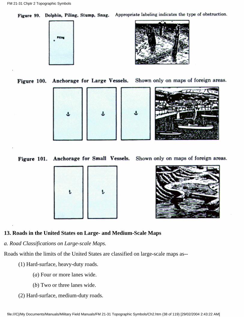
13. Roads in the United States on Large- and Medium-Scale Maps
a. Road Classifications on Large-scale Maps.
Roads within the limits of the United States are classified on large-scale maps as--
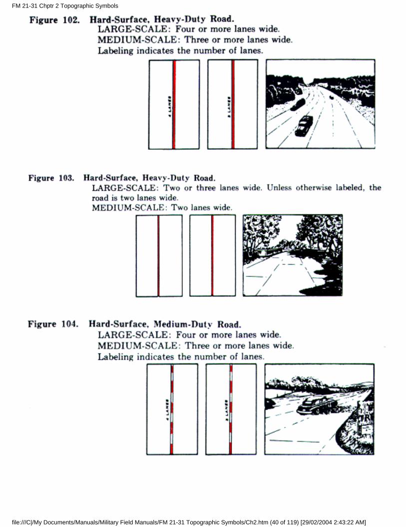
(1) Hard-surface, heavy-duty roads.
(a) Four or more lanes wide.
(b) Two or three lanes wide.
(2) Hard-surface, medium-duty roads.
FM 21-31 Chptr 2 Topographic Symbols
file:///C|/My Documents/Manuals/Military Field Manuals/FM 21-31 Topographic Symbols/Ch2.htm (38 of 119) [29/02/2004 2:43:22 AM]
(a) Four or more lanes wide.
(b) Two or three lanes wide.
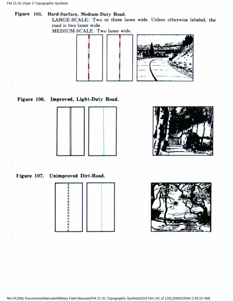
(3) Improved, light-duty roads.
(4) Unimproved dirt roads.
(5) Trails.
b. Road Classifications on Medium-Scale Maps. The classifications on medium-scale maps are the same,except for hard-surface roads, where a distinction is made between roads two lanes wide and roads morethan two lanes wide.
c. Hard-Surface, Heavy-Duty Roads. Roads of this classification carry heavy truck loads in all weatherwith a minimum of maintenance. The construction is usually of portland-cement concrete, bituminousconcrete, or sheet asphalt, rock asphalt, bituminous penetration, or mixed bituminous on a heavyfoundation. Brick or block roads are also included in this category.
d. Hard-Surface, Medium-Duty Roads. These roads carry medium-heavy truck loads in all weather.Occasional maintenance is required. Construction is usually a bituminous-penetration ormixed-bituminous surface, or bituminoustreated surface on a light foundation.
e. Improved, Light-Duty Roads. These roads carry light loads in all weather. Periodic maintenance isusually necessary. Construction consists of stabilized or oiled-surface gravel or stone, graded and drainedgravel or stone, or graded and drained soil surface. Included in this category are hard-surface roads lessthan two lanes wide and improved private roads which normally are not practical for use in rerouting oftraffic in emergencies.
f. Unimproved Dirt Roads. These roads are suitable only for light loads in dry weather. They are withoutsurface improvement and are seldom maintained. Included are abandoned roads, fire roads, and lumberroads.
g. Trails. The map shows important foot paths, foot trails, and pack trails which can accommodate ¼-tontrucks in dry weather. Minor and short connecting trails usually are omitted.
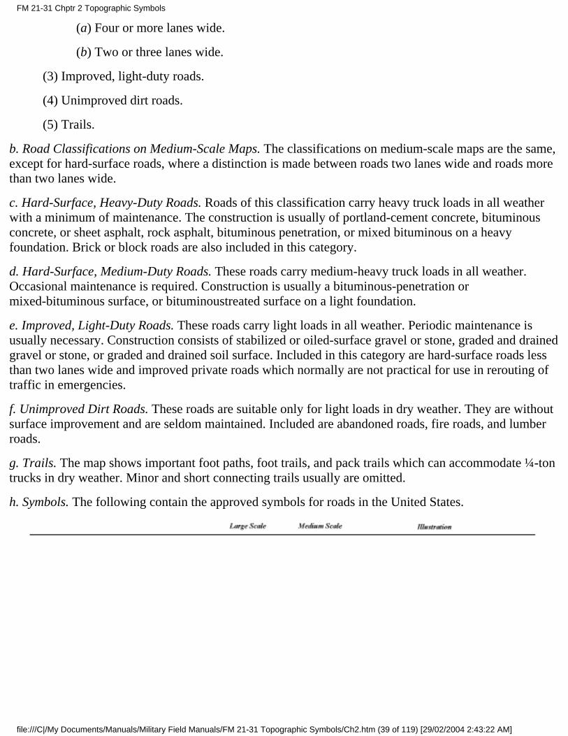
h. Symbols. The following contain the approved symbols for roads in the United States.
FM 21-31 Chptr 2 Topographic Symbols
file:///C|/My Documents/Manuals/Military Field Manuals/FM 21-31 Topographic Symbols/Ch2.htm (39 of 119) [29/02/2004 2:43:22 AM]
FM 21-31 Chptr 2 Topographic Symbols
file:///C|/My Documents/Manuals/Military Field Manuals/FM 21-31 Topographic Symbols/Ch2.htm (40 of 119) [29/02/2004 2:43:22 AM]
FM 21-31 Chptr 2 Topographic Symbols
file:///C|/My Documents/Manuals/Military Field Manuals/FM 21-31 Topographic Symbols/Ch2.htm (41 of 119) [29/02/2004 2:43:22 AM]
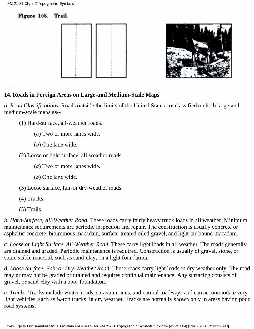
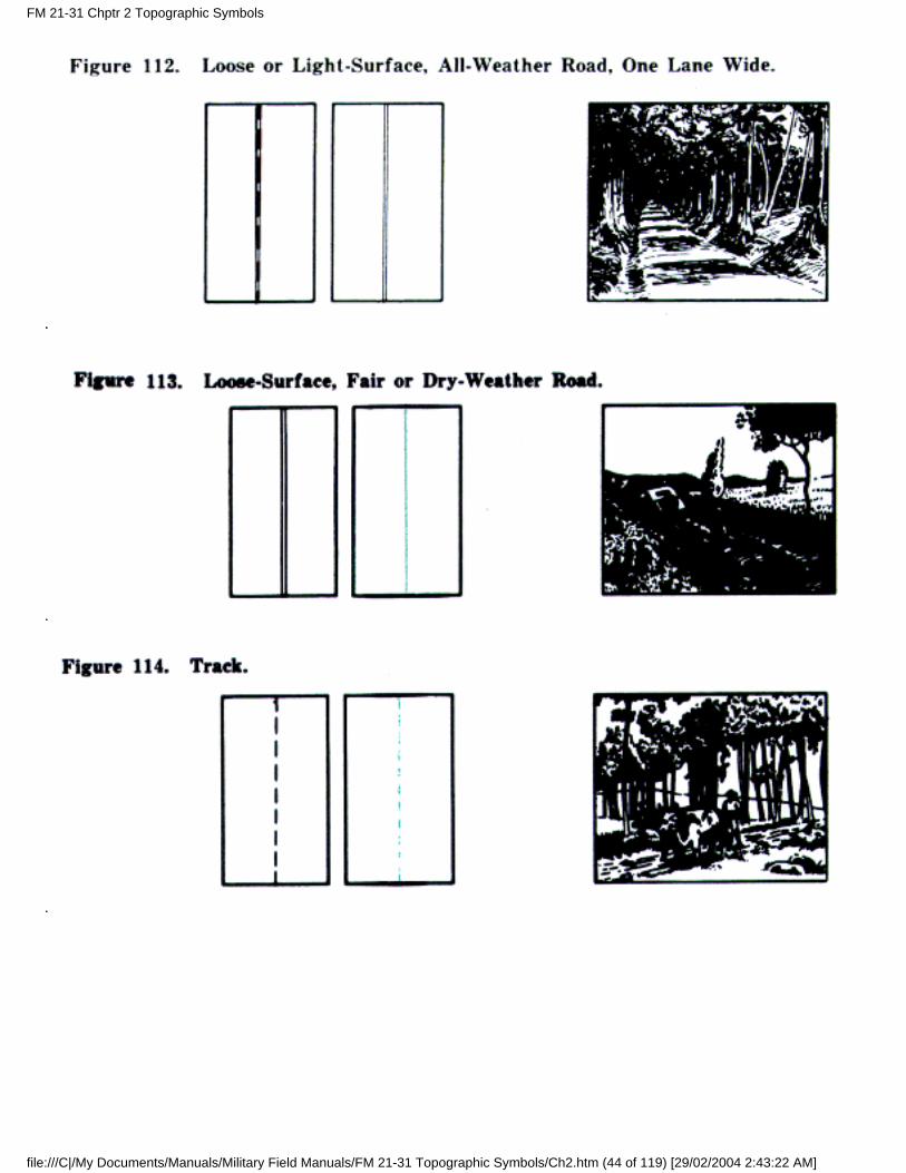
14. Roads in Foreign Areas on Large-and Medium-Scale Maps
a. Road Classifications. Roads outside the limits of the United States are classified on both large-andmedium-scale maps as--
(1) Hard-surface, all-weather roads.
(a) Two or more lanes wide.
(b) One lane wide.
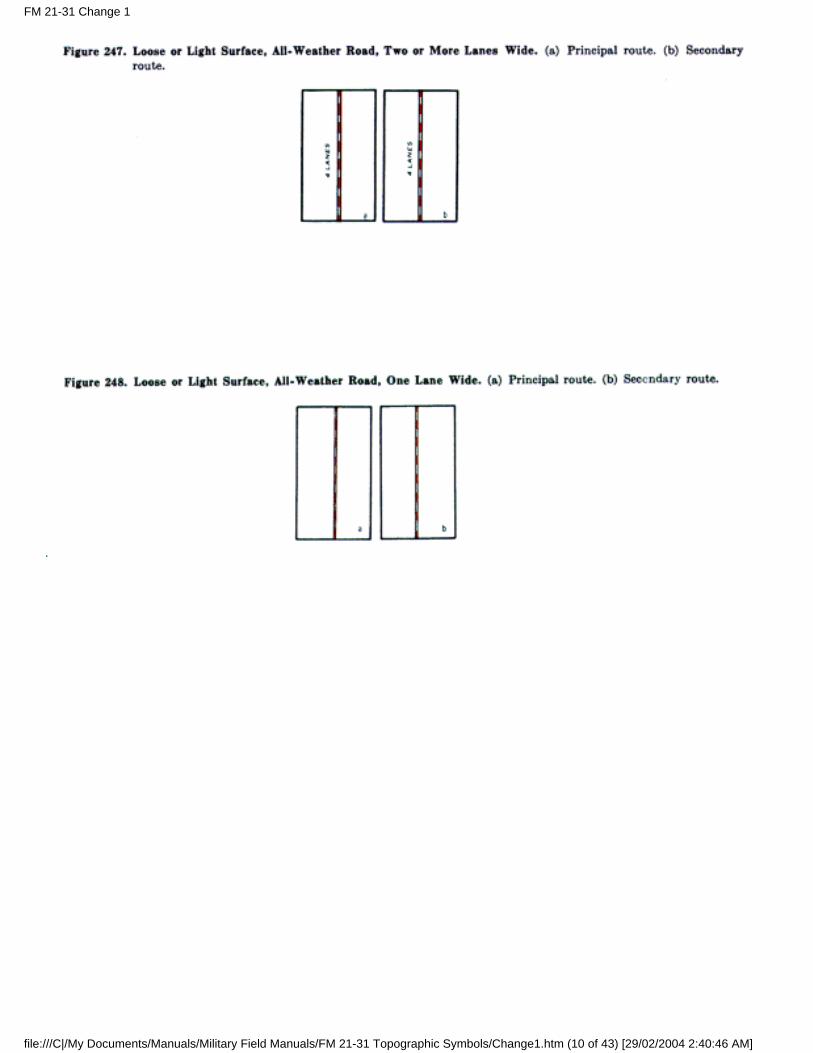
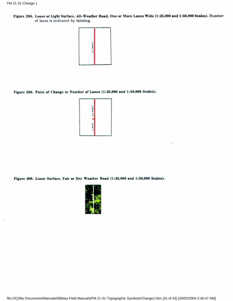
(2) Loose or light surface, all-weather roads.
(a) Two or more lanes wide.
(b) One lane wide.
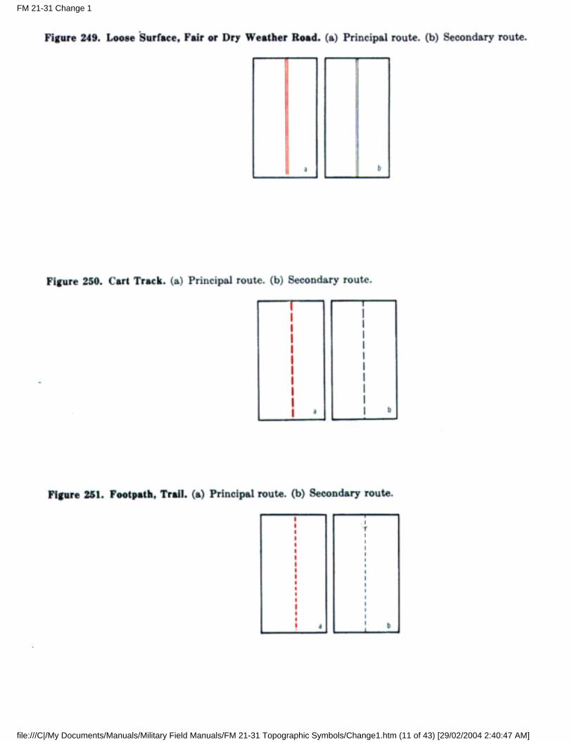
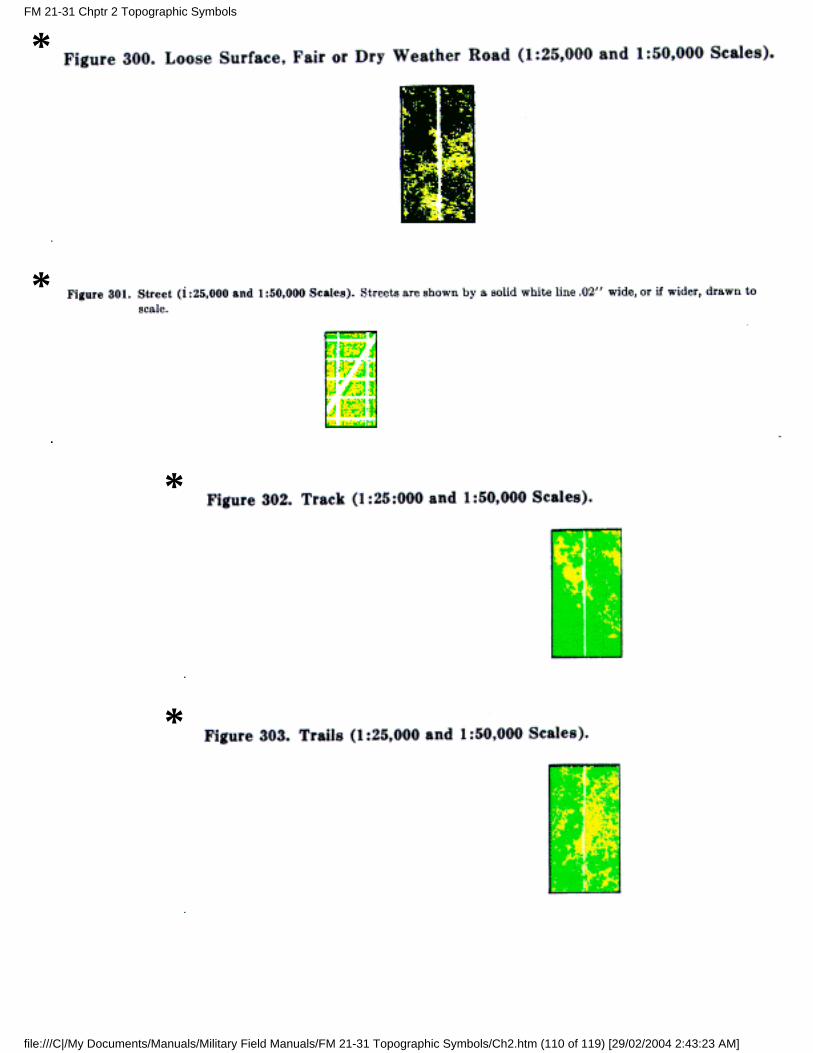
(3) Loose surface, fair-or dry-weather roads.
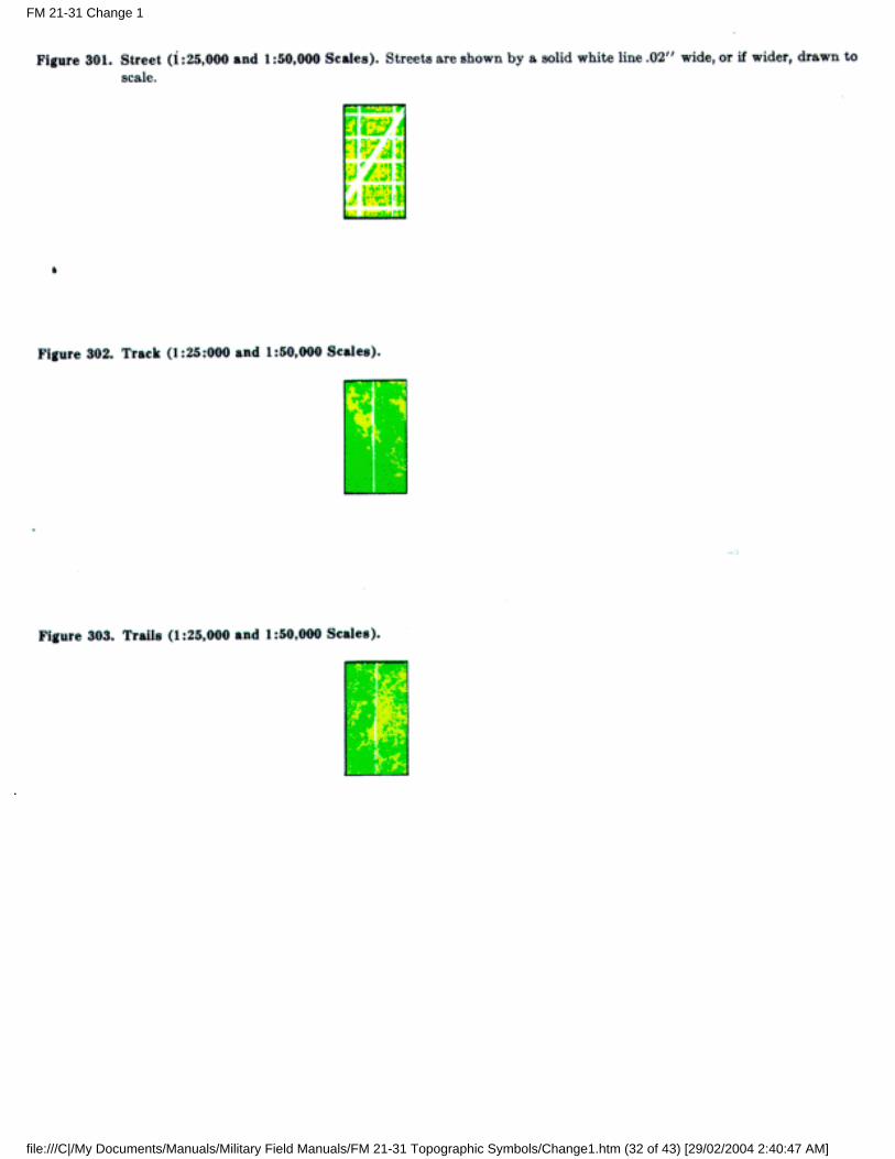
(4) Tracks.
(5) Trails.
b. Hard-Surface, All-Weather Road. These roads carry fairly heavy truck loads in all weather. Minimummaintenance requirements are periodic inspection and repair. The construction is usually concrete orasphaltic concrete, bituminous macadam, surface-treated oiled gravel, and light tar-bound macadam.
c. Loose or Light Surface, All-Weather Road. These carry light loads in all weather. The roads generallyare drained and graded. Periodic maintenance is required. Construction is usually of gravel, stone, orsome stable material, such as sand-clay, on a light foundation.
d. Loose Surface, Fair-or Dry-Weather Road. These roads carry light loads in dry weather only. The roadmay or may not be graded or drained and requires continual maintenance. Any surfacing consists ofgravel, or sand-clay with a poor foundation.
e. Tracks. Tracks include winter roads, caravan routes, and natural roadways and can accommodate verylight vehicles, such as ¼-ton trucks, in dry weather. Tracks are normally shown only in areas having poorroad systems.
FM 21-31 Chptr 2 Topographic Symbols
file:///C|/My Documents/Manuals/Military Field Manuals/FM 21-31 Topographic Symbols/Ch2.htm (42 of 119) [29/02/2004 2:43:22 AM]
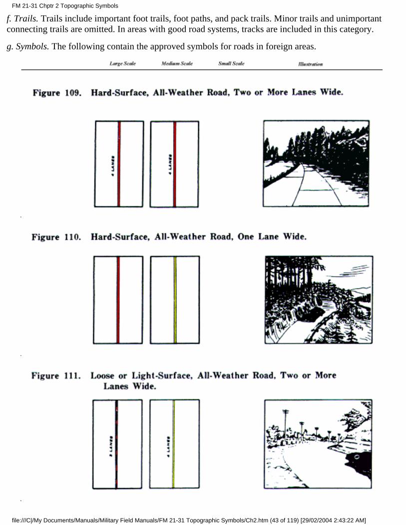
f. Trails. Trails include important foot trails, foot paths, and pack trails. Minor trails and unimportantconnecting trails are omitted. In areas with good road systems, tracks are included in this category.
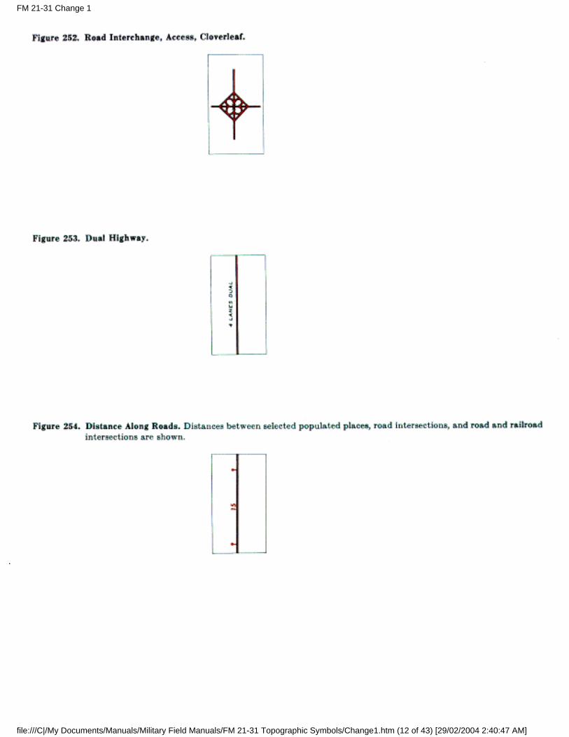
g. Symbols. The following contain the approved symbols for roads in foreign areas.
FM 21-31 Chptr 2 Topographic Symbols
file:///C|/My Documents/Manuals/Military Field Manuals/FM 21-31 Topographic Symbols/Ch2.htm (43 of 119) [29/02/2004 2:43:22 AM]
FM 21-31 Chptr 2 Topographic Symbols
file:///C|/My Documents/Manuals/Military Field Manuals/FM 21-31 Topographic Symbols/Ch2.htm (44 of 119) [29/02/2004 2:43:22 AM]
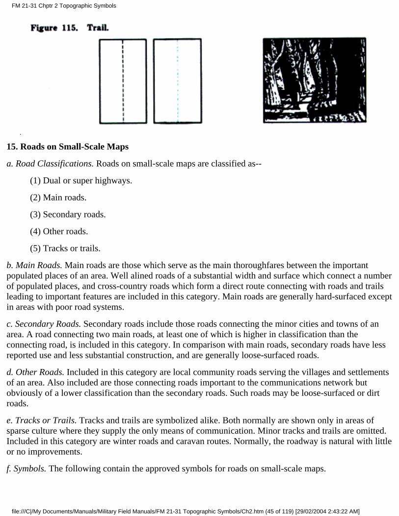
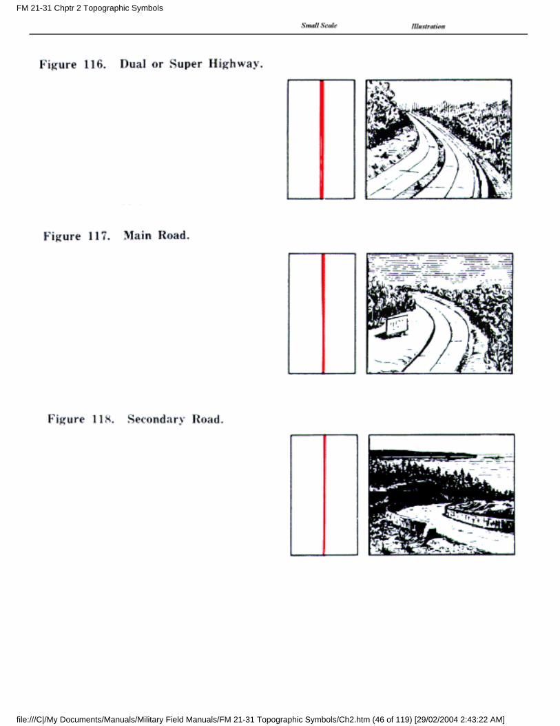
15. Roads on Small-Scale Maps
a. Road Classifications. Roads on small-scale maps are classified as--
(1) Dual or super highways.
(2) Main roads.
(3) Secondary roads.
(4) Other roads.
(5) Tracks or trails.
b. Main Roads. Main roads are those which serve as the main thoroughfares between the importantpopulated places of an area. Well alined roads of a substantial width and surface which connect a numberof populated places, and cross-country roads which form a direct route connecting with roads and trailsleading to important features are included in this category. Main roads are generally hard-surfaced exceptin areas with poor road systems.
c. Secondary Roads. Secondary roads include those roads connecting the minor cities and towns of anarea. A road connecting two main roads, at least one of which is higher in classification than theconnecting road, is included in this category. In comparison with main roads, secondary roads have lessreported use and less substantial construction, and are generally loose-surfaced roads.
d. Other Roads. Included in this category are local community roads serving the villages and settlementsof an area. Also included are those connecting roads important to the communications network butobviously of a lower classification than the secondary roads. Such roads may be loose-surfaced or dirtroads.
e. Tracks or Trails. Tracks and trails are symbolized alike. Both normally are shown only in areas ofsparse culture where they supply the only means of communication. Minor tracks and trails are omitted.Included in this category are winter roads and caravan routes. Normally, the roadway is natural with littleor no improvements.
f. Symbols. The following contain the approved symbols for roads on small-scale maps.
FM 21-31 Chptr 2 Topographic Symbols
file:///C|/My Documents/Manuals/Military Field Manuals/FM 21-31 Topographic Symbols/Ch2.htm (45 of 119) [29/02/2004 2:43:22 AM]
FM 21-31 Chptr 2 Topographic Symbols
file:///C|/My Documents/Manuals/Military Field Manuals/FM 21-31 Topographic Symbols/Ch2.htm (46 of 119) [29/02/2004 2:43:22 AM]
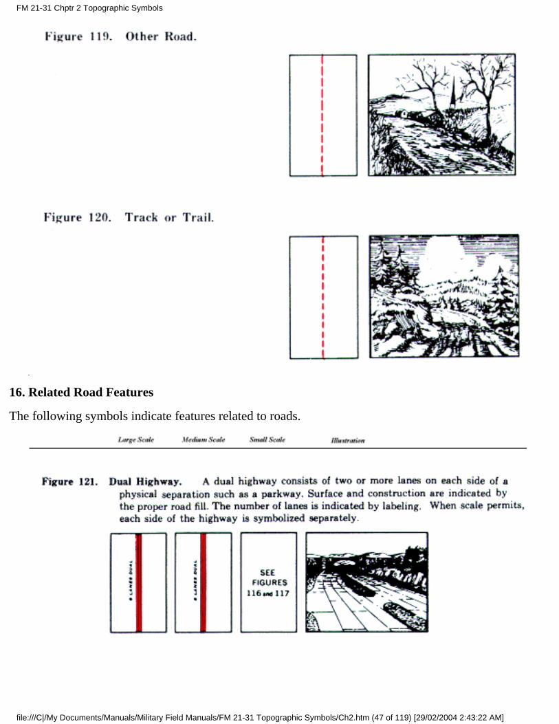
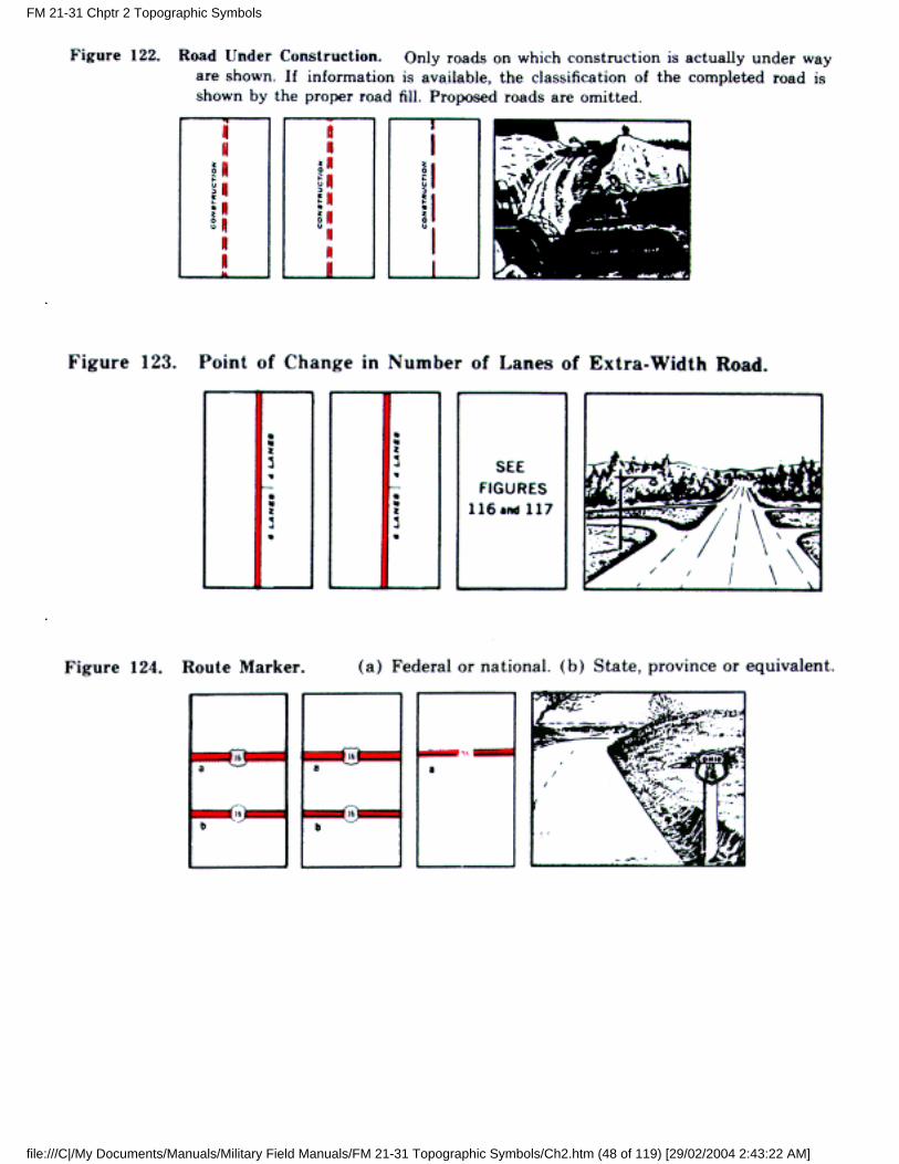
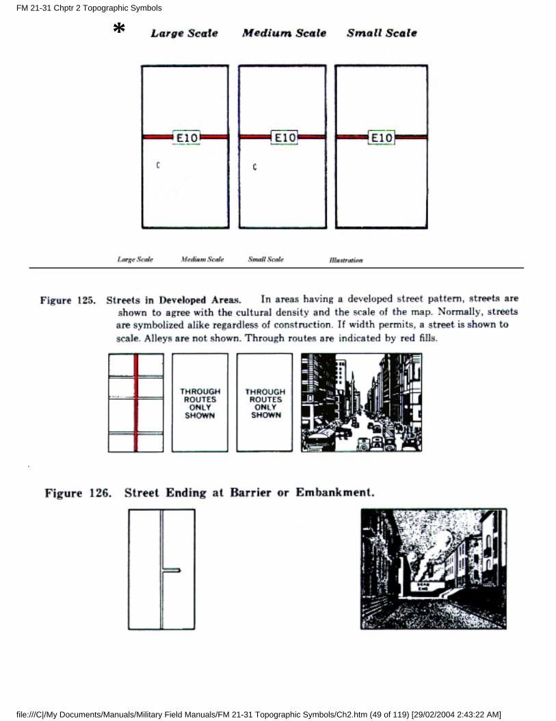
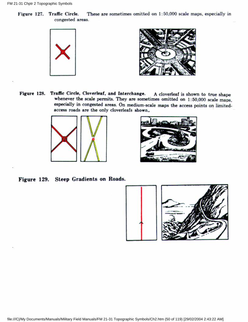
16. Related Road Features
The following symbols indicate features related to roads.
FM 21-31 Chptr 2 Topographic Symbols
file:///C|/My Documents/Manuals/Military Field Manuals/FM 21-31 Topographic Symbols/Ch2.htm (47 of 119) [29/02/2004 2:43:22 AM]
FM 21-31 Chptr 2 Topographic Symbols
file:///C|/My Documents/Manuals/Military Field Manuals/FM 21-31 Topographic Symbols/Ch2.htm (48 of 119) [29/02/2004 2:43:22 AM]
*FM 21-31 Chptr 2 Topographic Symbols
file:///C|/My Documents/Manuals/Military Field Manuals/FM 21-31 Topographic Symbols/Ch2.htm (49 of 119) [29/02/2004 2:43:22 AM]
FM 21-31 Chptr 2 Topographic Symbols
file:///C|/My Documents/Manuals/Military Field Manuals/FM 21-31 Topographic Symbols/Ch2.htm (50 of 119) [29/02/2004 2:43:22 AM]
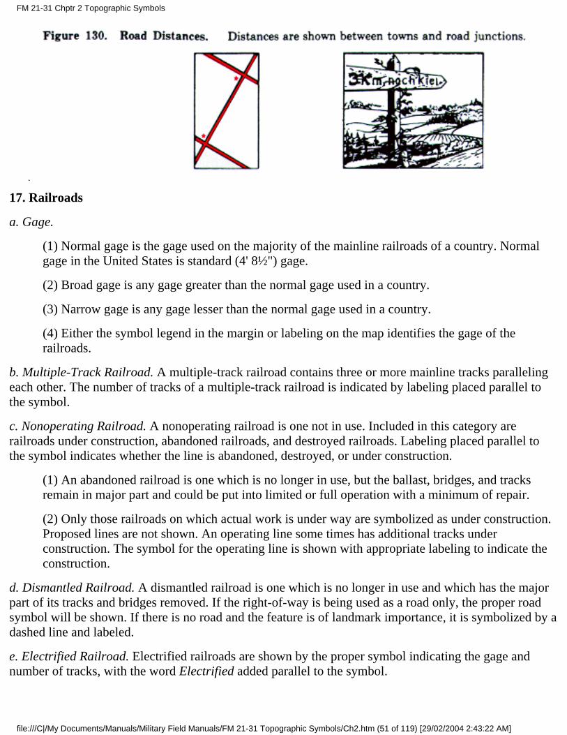
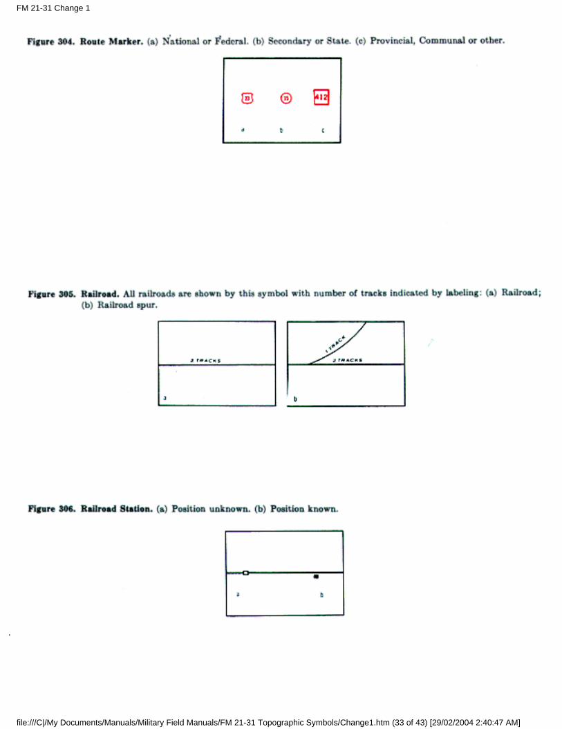
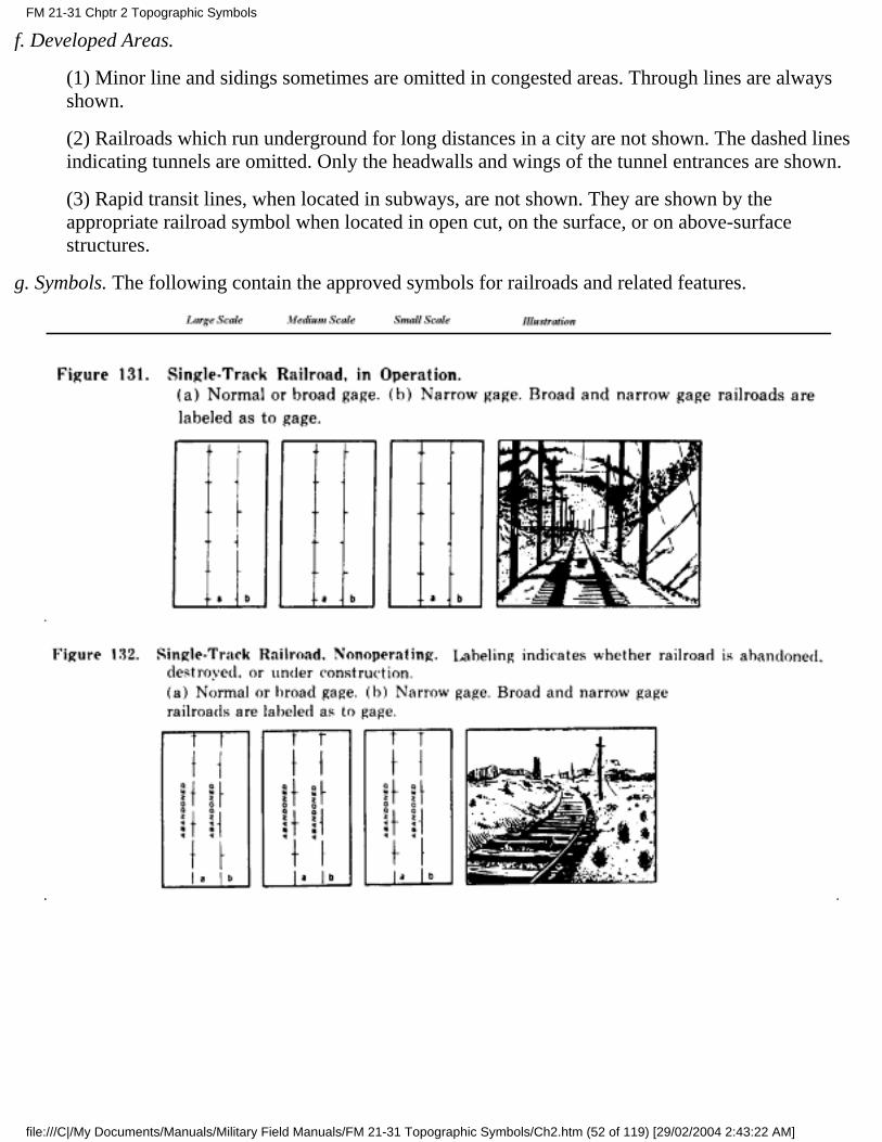
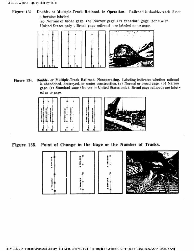
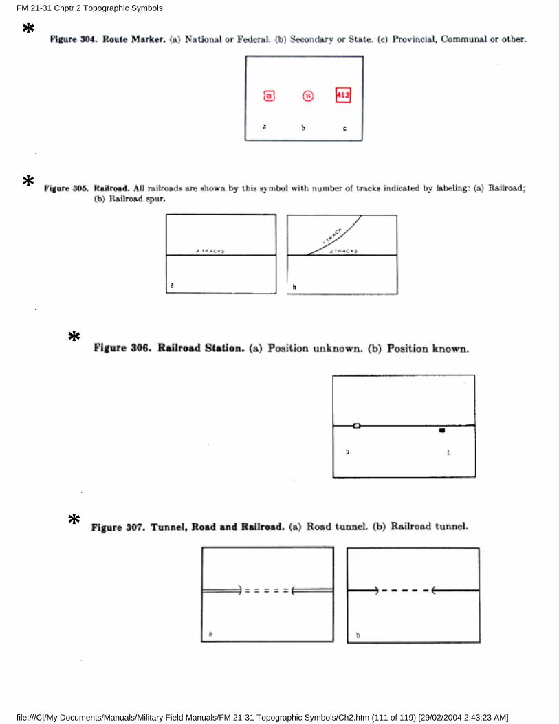
17. Railroads
a. Gage.
(1) Normal gage is the gage used on the majority of the mainline railroads of a country. Normalgage in the United States is standard (4' 8½") gage.
(2) Broad gage is any gage greater than the normal gage used in a country.
(3) Narrow gage is any gage lesser than the normal gage used in a country.
(4) Either the symbol legend in the margin or labeling on the map identifies the gage of therailroads.
b. Multiple-Track Railroad. A multiple-track railroad contains three or more mainline tracks parallelingeach other. The number of tracks of a multiple-track railroad is indicated by labeling placed parallel tothe symbol.
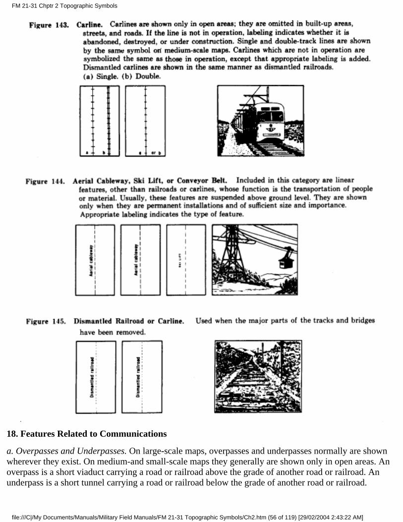
c. Nonoperating Railroad. A nonoperating railroad is one not in use. Included in this category arerailroads under construction, abandoned railroads, and destroyed railroads. Labeling placed parallel tothe symbol indicates whether the line is abandoned, destroyed, or under construction.
(1) An abandoned railroad is one which is no longer in use, but the ballast, bridges, and tracksremain in major part and could be put into limited or full operation with a minimum of repair.
(2) Only those railroads on which actual work is under way are symbolized as under construction.Proposed lines are not shown. An operating line some times has additional tracks underconstruction. The symbol for the operating line is shown with appropriate labeling to indicate theconstruction.
d. Dismantled Railroad. A dismantled railroad is one which is no longer in use and which has the majorpart of its tracks and bridges removed. If the right-of-way is being used as a road only, the proper roadsymbol will be shown. If there is no road and the feature is of landmark importance, it is symbolized by adashed line and labeled.
e. Electrified Railroad. Electrified railroads are shown by the proper symbol indicating the gage andnumber of tracks, with the word Electrified added parallel to the symbol.
FM 21-31 Chptr 2 Topographic Symbols
file:///C|/My Documents/Manuals/Military Field Manuals/FM 21-31 Topographic Symbols/Ch2.htm (51 of 119) [29/02/2004 2:43:22 AM]
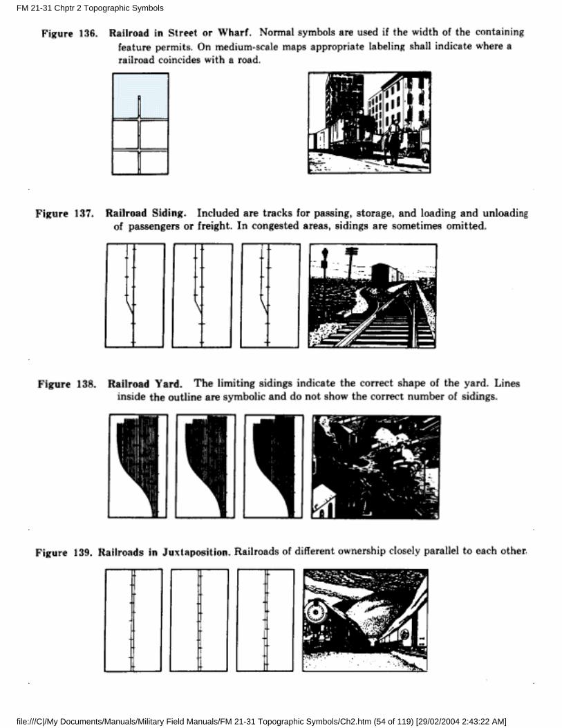
f. Developed Areas.
(1) Minor line and sidings sometimes are omitted in congested areas. Through lines are alwaysshown.
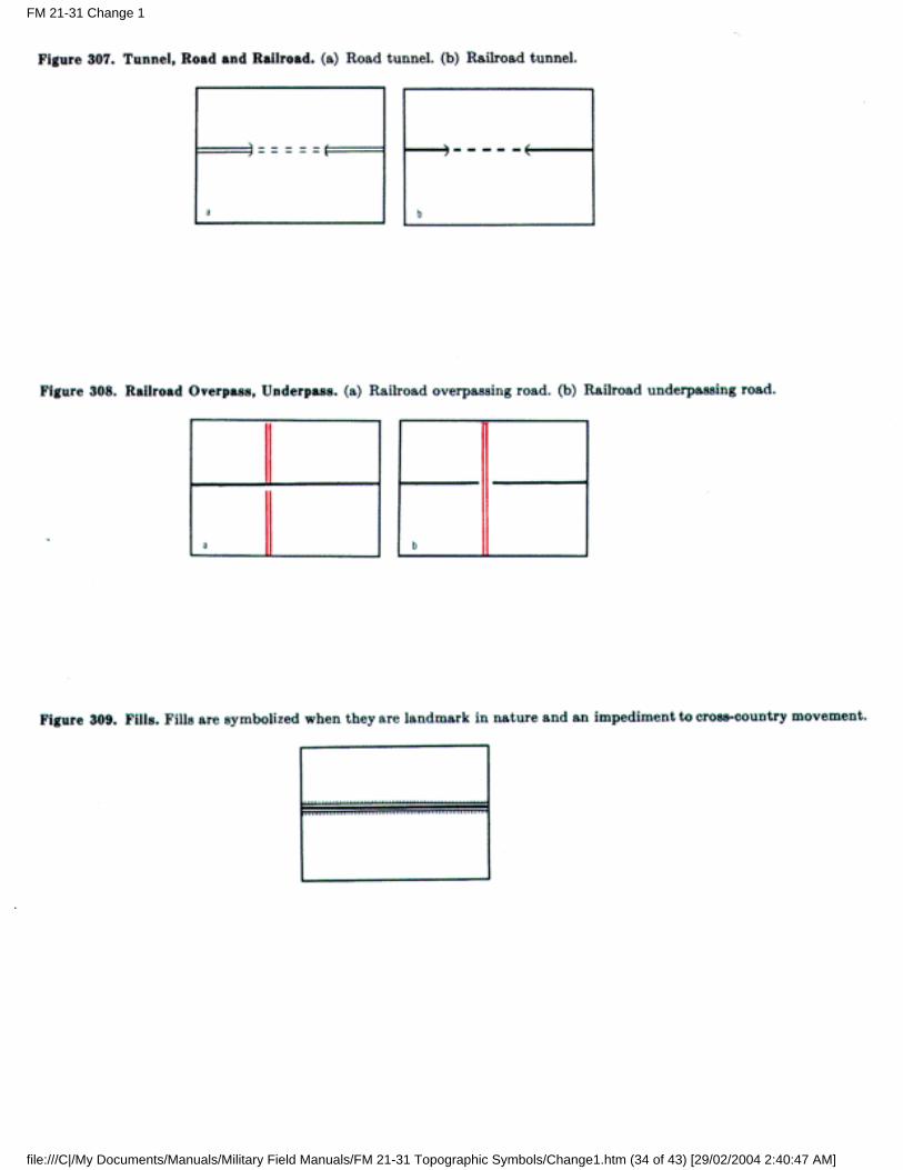
(2) Railroads which run underground for long distances in a city are not shown. The dashed linesindicating tunnels are omitted. Only the headwalls and wings of the tunnel entrances are shown.
(3) Rapid transit lines, when located in subways, are not shown. They are shown by theappropriate railroad symbol when located in open cut, on the surface, or on above-surfacestructures.
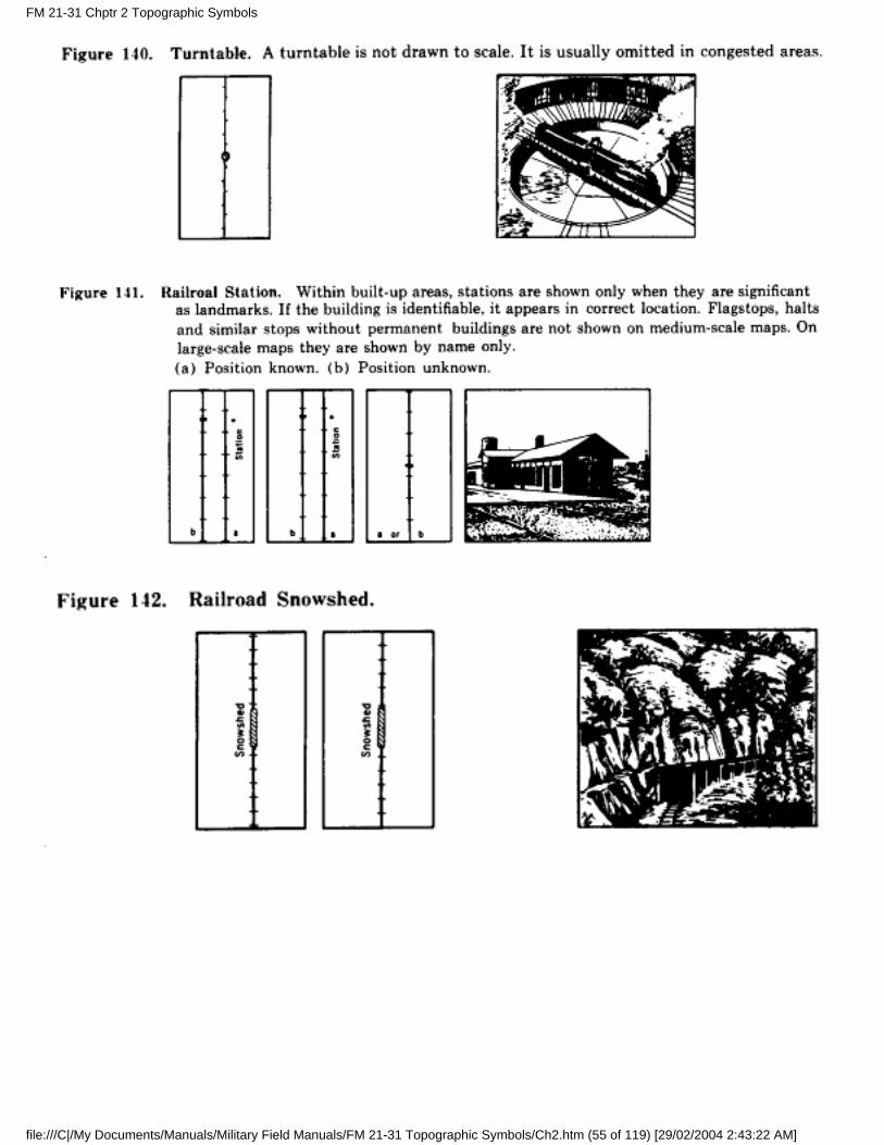
g. Symbols. The following contain the approved symbols for railroads and related features.
FM 21-31 Chptr 2 Topographic Symbols
file:///C|/My Documents/Manuals/Military Field Manuals/FM 21-31 Topographic Symbols/Ch2.htm (52 of 119) [29/02/2004 2:43:22 AM]
FM 21-31 Chptr 2 Topographic Symbols
file:///C|/My Documents/Manuals/Military Field Manuals/FM 21-31 Topographic Symbols/Ch2.htm (53 of 119) [29/02/2004 2:43:22 AM]
FM 21-31 Chptr 2 Topographic Symbols
file:///C|/My Documents/Manuals/Military Field Manuals/FM 21-31 Topographic Symbols/Ch2.htm (54 of 119) [29/02/2004 2:43:22 AM]
FM 21-31 Chptr 2 Topographic Symbols
file:///C|/My Documents/Manuals/Military Field Manuals/FM 21-31 Topographic Symbols/Ch2.htm (55 of 119) [29/02/2004 2:43:22 AM]
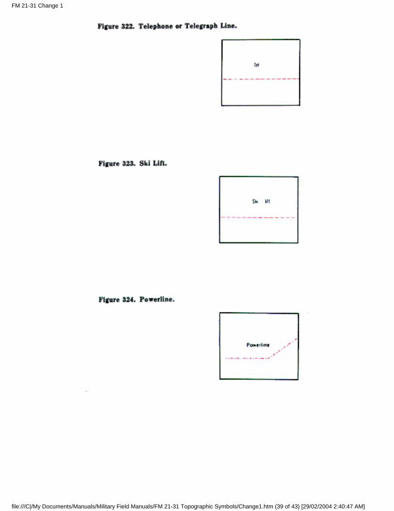
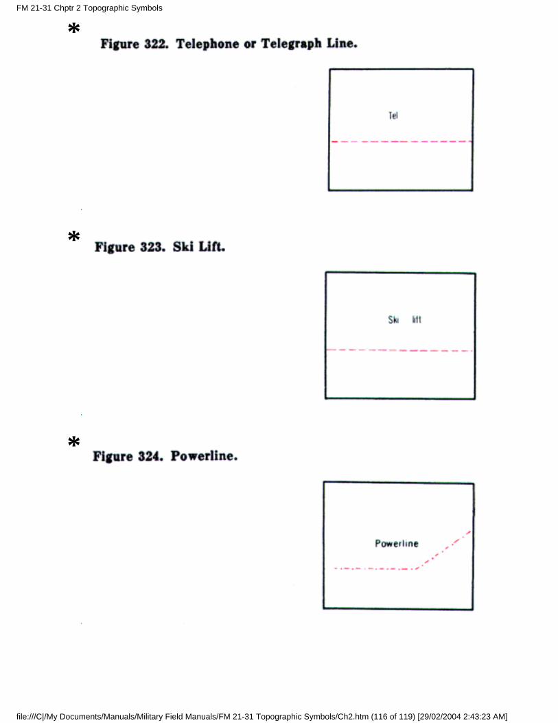
18. Features Related to Communications
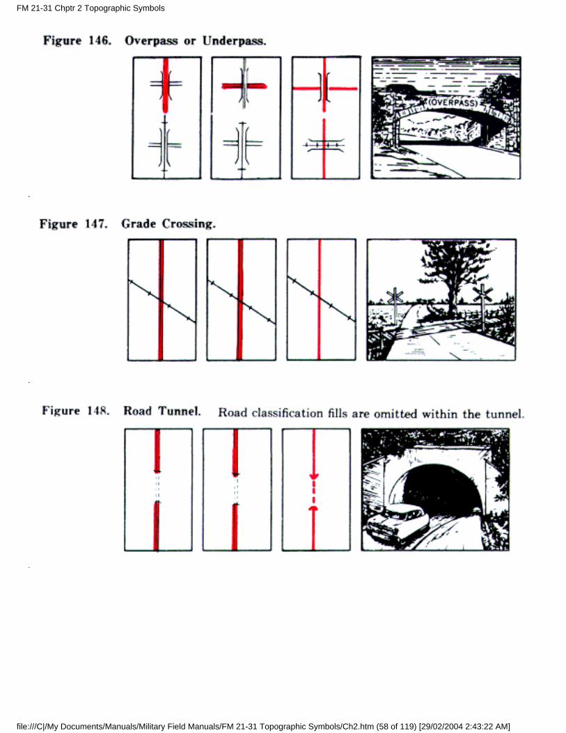
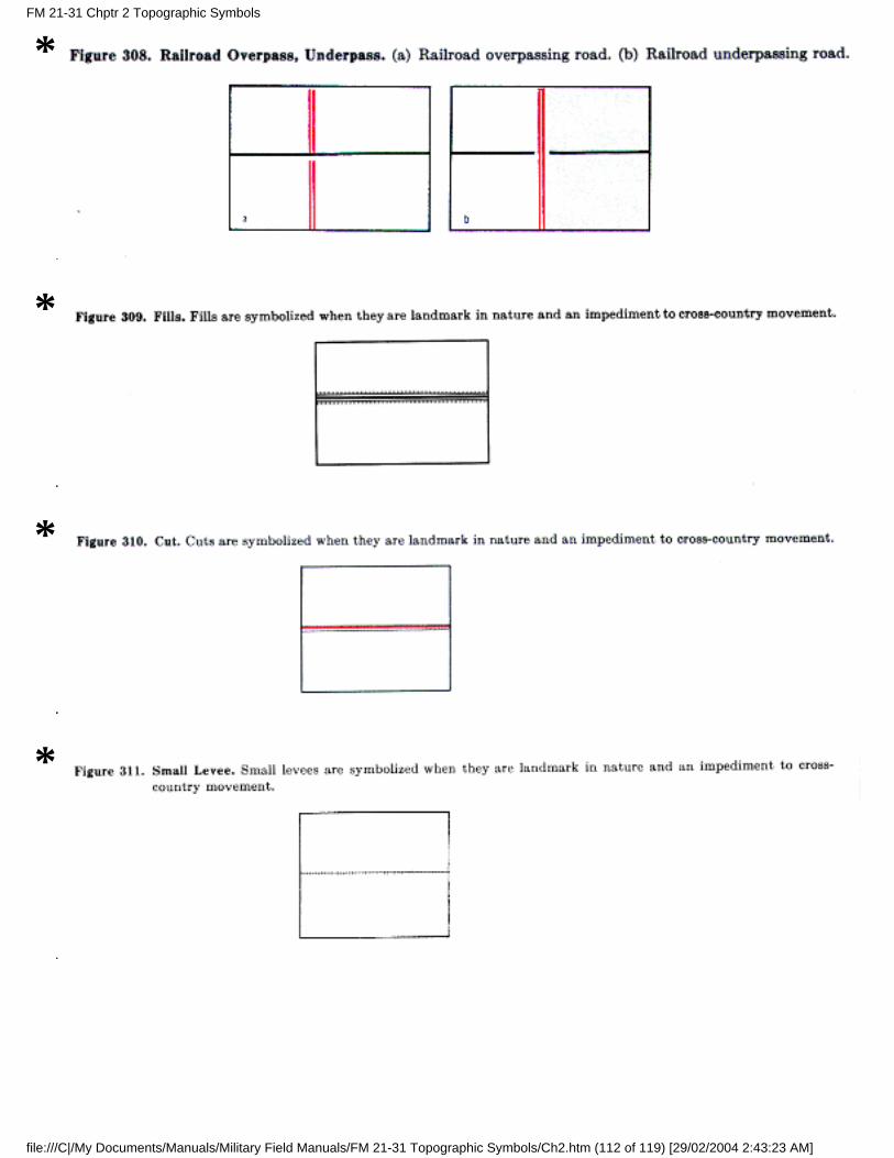
a. Overpasses and Underpasses. On large-scale maps, overpasses and underpasses normally are shownwherever they exist. On medium-and small-scale maps they generally are shown only in open areas. Anoverpass is a short viaduct carrying a road or railroad above the grade of another road or railroad. Anunderpass is a short tunnel carrying a road or railroad below the grade of another road or railroad.
FM 21-31 Chptr 2 Topographic Symbols
file:///C|/My Documents/Manuals/Military Field Manuals/FM 21-31 Topographic Symbols/Ch2.htm (56 of 119) [29/02/2004 2:43:22 AM]
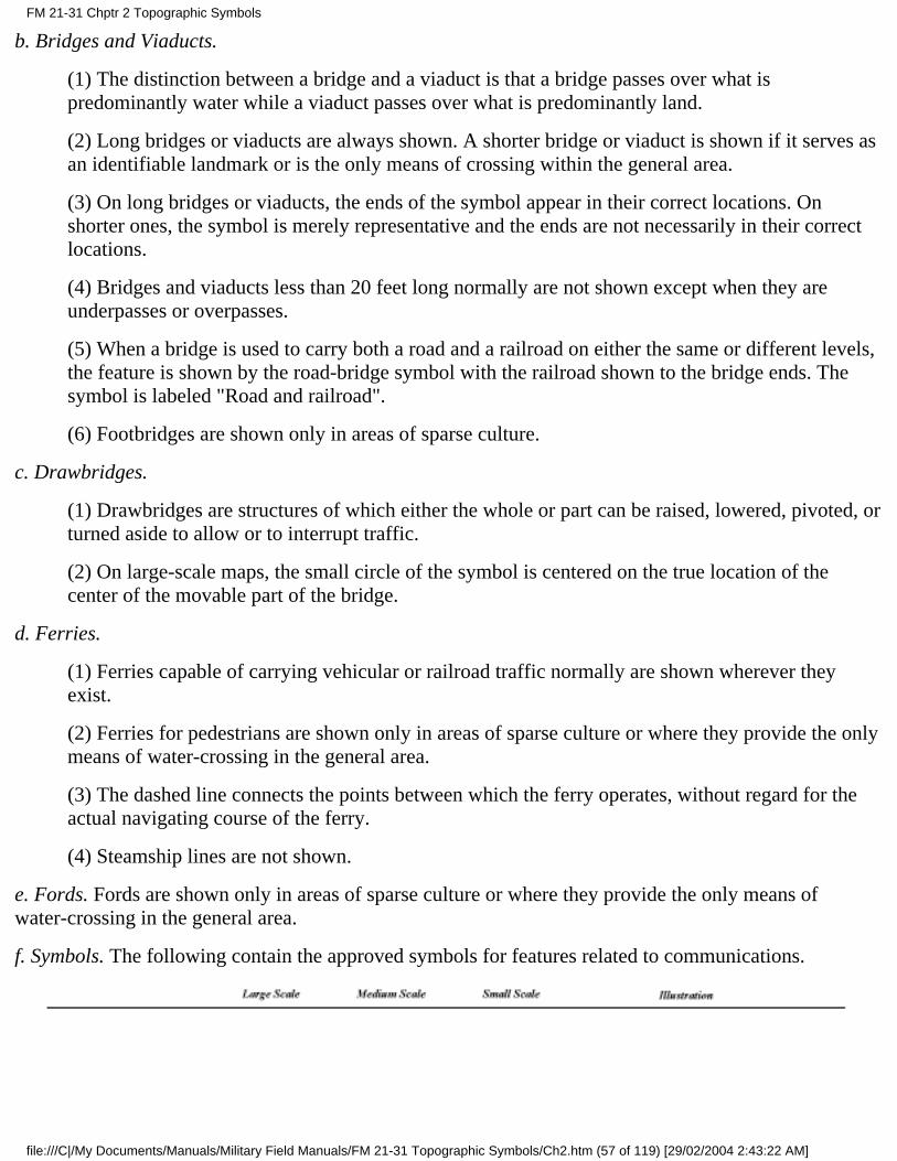
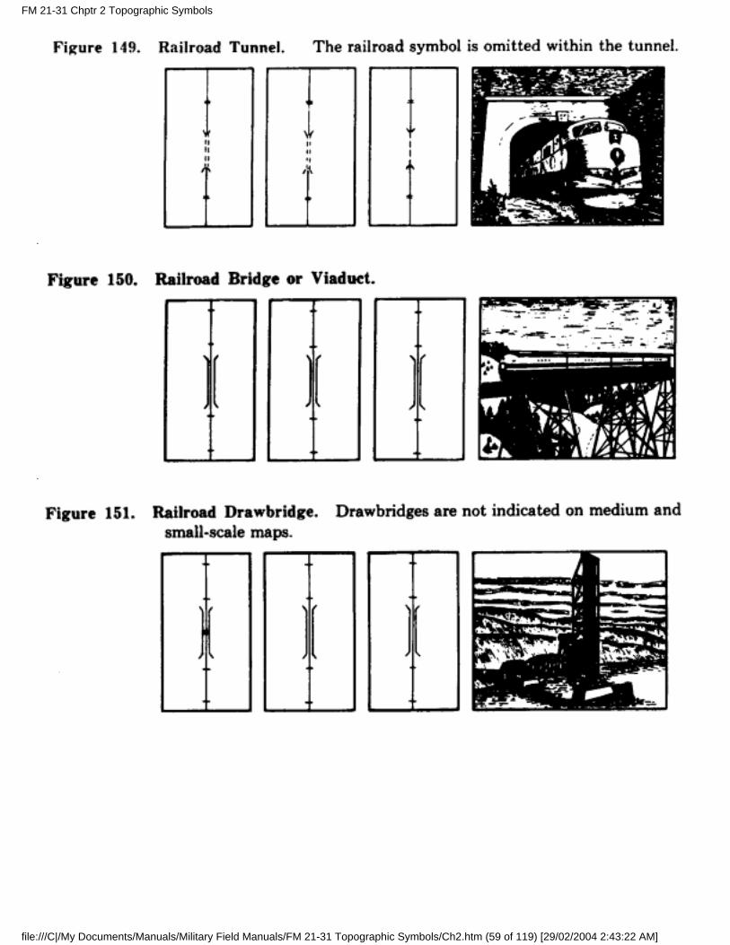
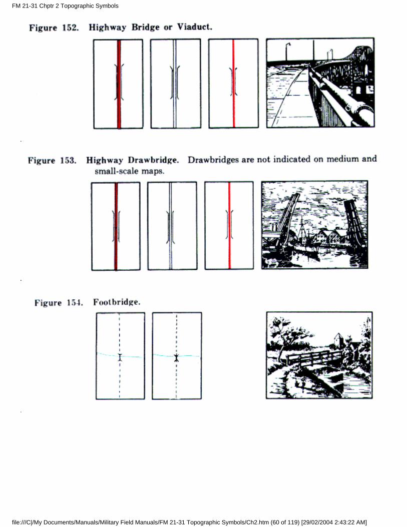
b. Bridges and Viaducts.
(1) The distinction between a bridge and a viaduct is that a bridge passes over what ispredominantly water while a viaduct passes over what is predominantly land.
(2) Long bridges or viaducts are always shown. A shorter bridge or viaduct is shown if it serves asan identifiable landmark or is the only means of crossing within the general area.
(3) On long bridges or viaducts, the ends of the symbol appear in their correct locations. Onshorter ones, the symbol is merely representative and the ends are not necessarily in their correctlocations.
(4) Bridges and viaducts less than 20 feet long normally are not shown except when they areunderpasses or overpasses.
(5) When a bridge is used to carry both a road and a railroad on either the same or different levels,the feature is shown by the road-bridge symbol with the railroad shown to the bridge ends. Thesymbol is labeled "Road and railroad".
(6) Footbridges are shown only in areas of sparse culture.
c. Drawbridges.
(1) Drawbridges are structures of which either the whole or part can be raised, lowered, pivoted, orturned aside to allow or to interrupt traffic.
(2) On large-scale maps, the small circle of the symbol is centered on the true location of thecenter of the movable part of the bridge.
d. Ferries.
(1) Ferries capable of carrying vehicular or railroad traffic normally are shown wherever theyexist.
(2) Ferries for pedestrians are shown only in areas of sparse culture or where they provide the onlymeans of water-crossing in the general area.
(3) The dashed line connects the points between which the ferry operates, without regard for theactual navigating course of the ferry.
(4) Steamship lines are not shown.
e. Fords. Fords are shown only in areas of sparse culture or where they provide the only means ofwater-crossing in the general area.
f. Symbols. The following contain the approved symbols for features related to communications.
FM 21-31 Chptr 2 Topographic Symbols
file:///C|/My Documents/Manuals/Military Field Manuals/FM 21-31 Topographic Symbols/Ch2.htm (57 of 119) [29/02/2004 2:43:22 AM]
FM 21-31 Chptr 2 Topographic Symbols
file:///C|/My Documents/Manuals/Military Field Manuals/FM 21-31 Topographic Symbols/Ch2.htm (58 of 119) [29/02/2004 2:43:22 AM]
FM 21-31 Chptr 2 Topographic Symbols
file:///C|/My Documents/Manuals/Military Field Manuals/FM 21-31 Topographic Symbols/Ch2.htm (59 of 119) [29/02/2004 2:43:22 AM]
FM 21-31 Chptr 2 Topographic Symbols
file:///C|/My Documents/Manuals/Military Field Manuals/FM 21-31 Topographic Symbols/Ch2.htm (60 of 119) [29/02/2004 2:43:22 AM]

19. Buildings and Populated Places on Large-Scale Maps
a. Built-Up Areas.
(1) A built-up area is a large continuous area which is developed or is in the advanced stage ofdevelopment for occupancy by concentrated populations. It usually is laid out in a definite streetpattern and normally contains a business or industrial district. Since all buildings cannot be shownindividually, the area is indicated by an overall screened red tint.
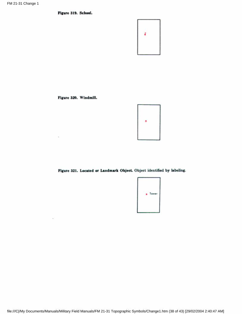
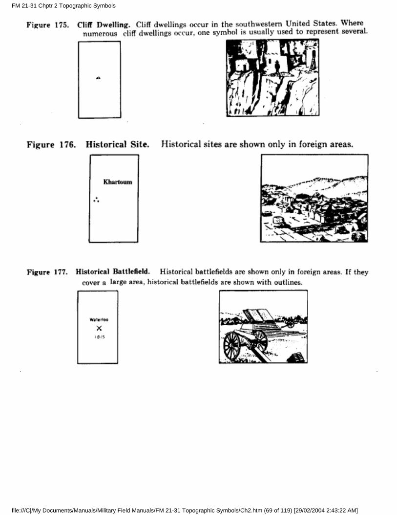
(2) Only landmark buildings are shown individually in built-up areas. These are buildings whichare prominent because of size, location, or usage, such as government or public buildings,colleges, schools, churches, hospitals, railroad stations, markets, factories, and buildings ofhistorical or cultural interest.
(3) Within the general outline of the built-up area, individual symbols are used and the built-uparea tint is generally omitted for the following features:
(a) Parks and cemeteries equivalent to or larger than one block.
(b) Institutions such as colleges, schools, and hospitals possessing open ground areasequivalent to or larger than one block.
(c) Section with little construction or development if equivalent to or larger than two blocks.
FM 21-31 Chptr 2 Topographic Symbols
file:///C|/My Documents/Manuals/Military Field Manuals/FM 21-31 Topographic Symbols/Ch2.htm (61 of 119) [29/02/2004 2:43:22 AM]
(4) All woodland cover is omitted in built-up areas.
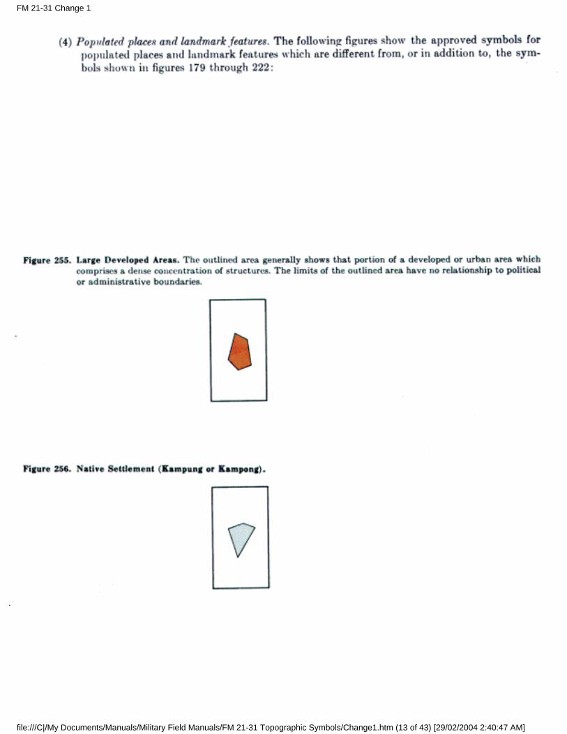
b. Native Settlements. These include native settlements in foreign areas in which the buildings are notusually of permanent construction. Kampongs in southwestern Asia and encampments in western Africaare examples. The symbol legend of the map defines the symbol properly.
c. Buildings in General.
(1) Conventional symbols are used to show a small building or a small structure similar to abuilding. The symbol is shown in correct orientation and its center usually coincides with thecorrect location of the center of the structure.
(2) Buildings and similar structures whose plotted size exceeds the conventional symbols areshown in correct orientation and shape and usually in correct location.
(3) Buildings and structures located along roads are shown in their correct location unless theywould then fall within the road. In such cases, the symbol is moved back.
(4) In many cases it is impossible to show all buildings because of congestion. The map retains thegeneral shape and pattern of the area and omits the less important buildings.
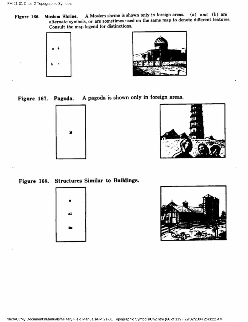
d. Structures Similar to Buildings.
(1) These are features of substantial construction not definable as buildings. In many instancesthey are roofed, although not necessarily enclosed on all sides. The term includes barns,grandstands, railroad sheds, large open sheds, fruit packing sheds, snow sheds, open-air refineries,and similar structures.
(2) Structures which are smaller than the average dwelling in the locality are not shown.
(3) In foreign areas, when information is unavailable, no distinction is made between buildings andstructures similar to buildings.
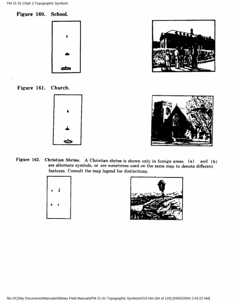
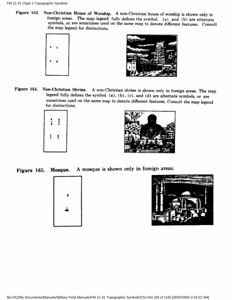
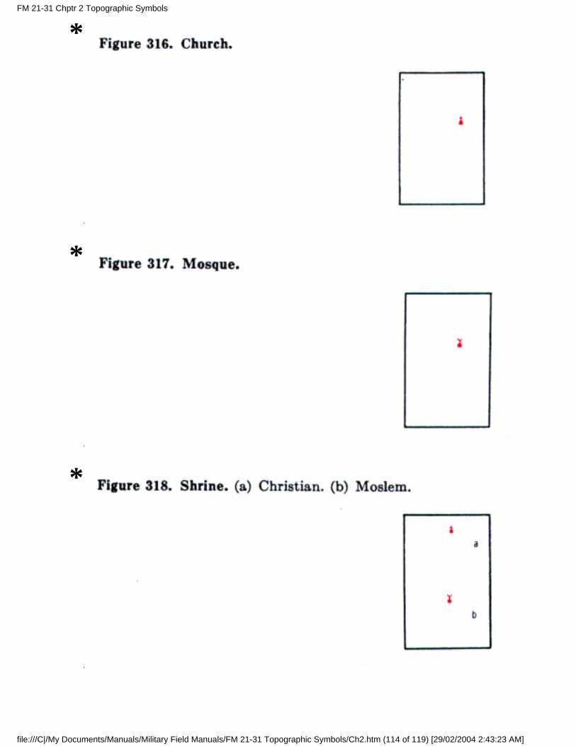
e. Schools and Churches.
(1) When a building is used both as a church and a school, it is symbolized as a school.
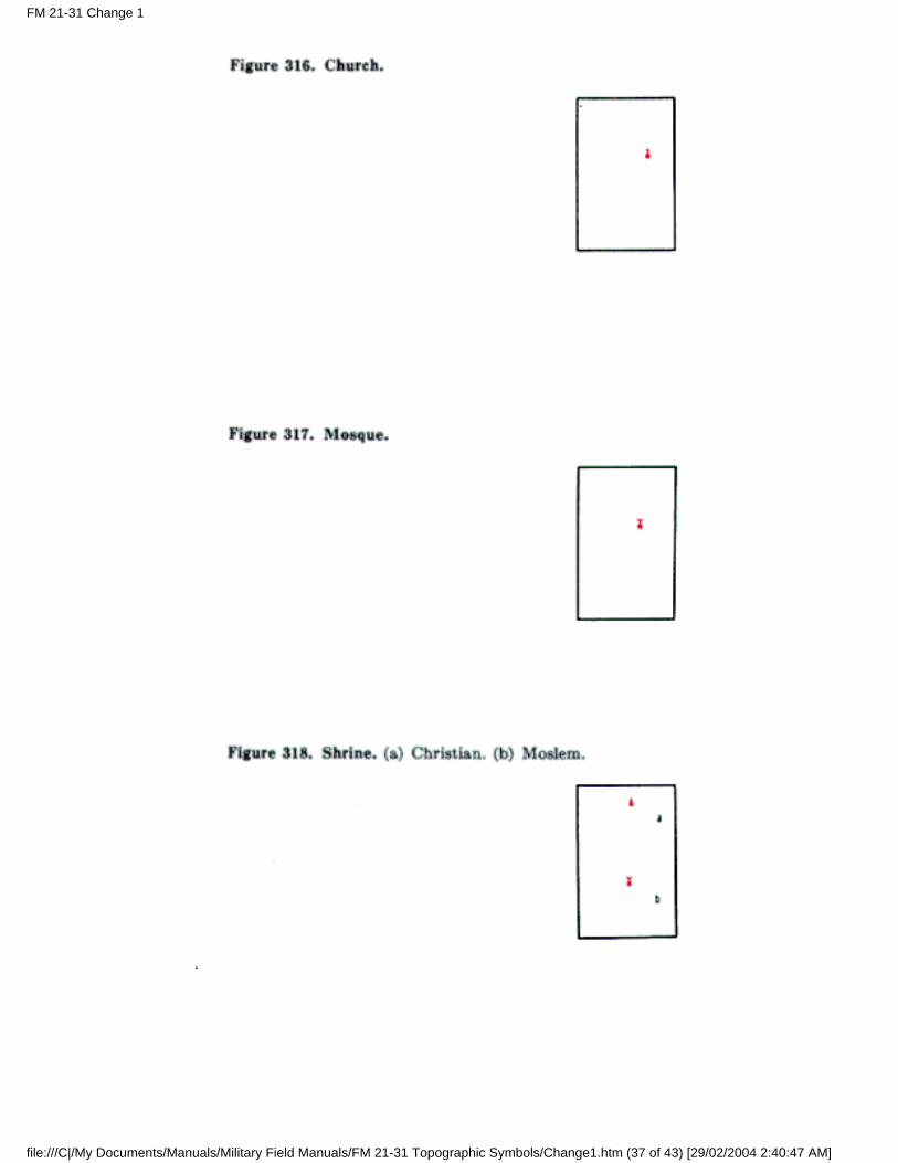
(2) In the United States, the church symbol is used commonly for all denominations. On maps offoreign areas, this symbol usually denotes a Christian place of worship, with other symbols beingused to denote places of worship of other sects. In such cases, the marginal symbol legend shouldbe consulted for detailed information.
(3) When a school has numerous buildings, the flag symbol is shown only on the administrationbuilding or the most prominent building in the group.
(4) When there are numerous religious buildings in a group, as in a convent or monastery, thecross symbol is shown only on the building used for religious services or the most prominentbuilding in the group.
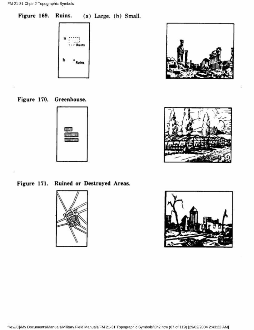
f. Ruins. Ruins are buildings or structures in such a state of dilapidation or decay that they can no longerbe used for their original purpose. Ruins which are smaller than the average dwelling in the locality arenot shown unless they possess unusual significance.
FM 21-31 Chptr 2 Topographic Symbols
file:///C|/My Documents/Manuals/Military Field Manuals/FM 21-31 Topographic Symbols/Ch2.htm (62 of 119) [29/02/2004 2:43:22 AM]
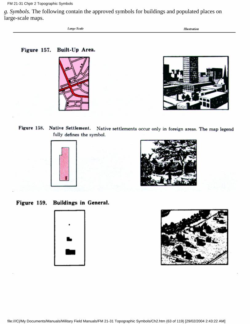
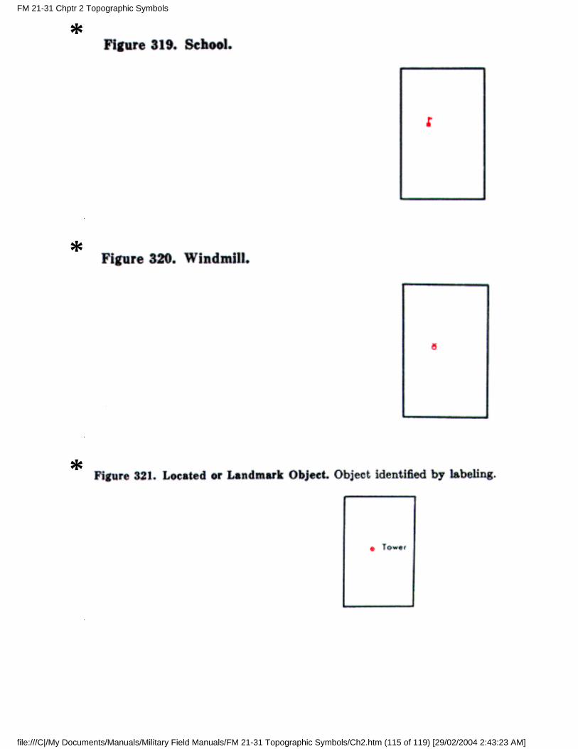
g. Symbols. The following contain the approved symbols for buildings and populated places onlarge-scale maps.
FM 21-31 Chptr 2 Topographic Symbols
file:///C|/My Documents/Manuals/Military Field Manuals/FM 21-31 Topographic Symbols/Ch2.htm (63 of 119) [29/02/2004 2:43:22 AM]
FM 21-31 Chptr 2 Topographic Symbols
file:///C|/My Documents/Manuals/Military Field Manuals/FM 21-31 Topographic Symbols/Ch2.htm (64 of 119) [29/02/2004 2:43:22 AM]
FM 21-31 Chptr 2 Topographic Symbols
file:///C|/My Documents/Manuals/Military Field Manuals/FM 21-31 Topographic Symbols/Ch2.htm (65 of 119) [29/02/2004 2:43:22 AM]
FM 21-31 Chptr 2 Topographic Symbols
file:///C|/My Documents/Manuals/Military Field Manuals/FM 21-31 Topographic Symbols/Ch2.htm (66 of 119) [29/02/2004 2:43:22 AM]
FM 21-31 Chptr 2 Topographic Symbols
file:///C|/My Documents/Manuals/Military Field Manuals/FM 21-31 Topographic Symbols/Ch2.htm (67 of 119) [29/02/2004 2:43:22 AM]
FM 21-31 Chptr 2 Topographic Symbols
file:///C|/My Documents/Manuals/Military Field Manuals/FM 21-31 Topographic Symbols/Ch2.htm (68 of 119) [29/02/2004 2:43:22 AM]
FM 21-31 Chptr 2 Topographic Symbols
file:///C|/My Documents/Manuals/Military Field Manuals/FM 21-31 Topographic Symbols/Ch2.htm (69 of 119) [29/02/2004 2:43:22 AM]
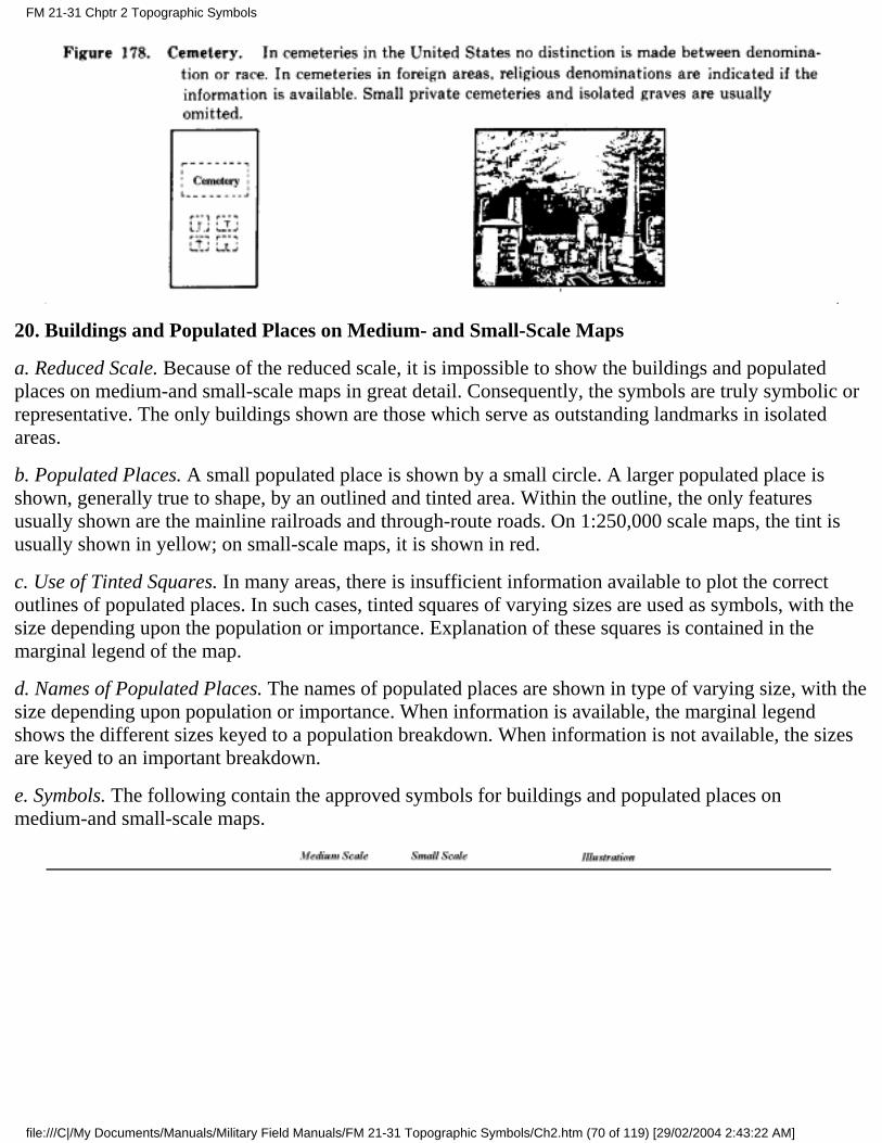
20. Buildings and Populated Places on Medium- and Small-Scale Maps
a. Reduced Scale. Because of the reduced scale, it is impossible to show the buildings and populatedplaces on medium-and small-scale maps in great detail. Consequently, the symbols are truly symbolic orrepresentative. The only buildings shown are those which serve as outstanding landmarks in isolatedareas.
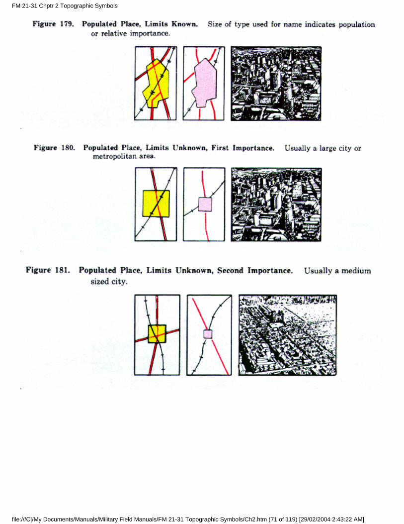
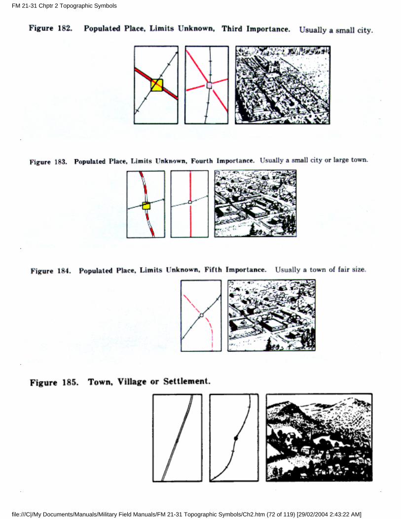
b. Populated Places. A small populated place is shown by a small circle. A larger populated place isshown, generally true to shape, by an outlined and tinted area. Within the outline, the only featuresusually shown are the mainline railroads and through-route roads. On 1:250,000 scale maps, the tint isusually shown in yellow; on small-scale maps, it is shown in red.
c. Use of Tinted Squares. In many areas, there is insufficient information available to plot the correctoutlines of populated places. In such cases, tinted squares of varying sizes are used as symbols, with thesize depending upon the population or importance. Explanation of these squares is contained in themarginal legend of the map.
d. Names of Populated Places. The names of populated places are shown in type of varying size, with thesize depending upon population or importance. When information is available, the marginal legendshows the different sizes keyed to a population breakdown. When information is not available, the sizesare keyed to an important breakdown.
e. Symbols. The following contain the approved symbols for buildings and populated places onmedium-and small-scale maps.
FM 21-31 Chptr 2 Topographic Symbols
file:///C|/My Documents/Manuals/Military Field Manuals/FM 21-31 Topographic Symbols/Ch2.htm (70 of 119) [29/02/2004 2:43:22 AM]
FM 21-31 Chptr 2 Topographic Symbols
file:///C|/My Documents/Manuals/Military Field Manuals/FM 21-31 Topographic Symbols/Ch2.htm (71 of 119) [29/02/2004 2:43:22 AM]
FM 21-31 Chptr 2 Topographic Symbols
file:///C|/My Documents/Manuals/Military Field Manuals/FM 21-31 Topographic Symbols/Ch2.htm (72 of 119) [29/02/2004 2:43:22 AM]
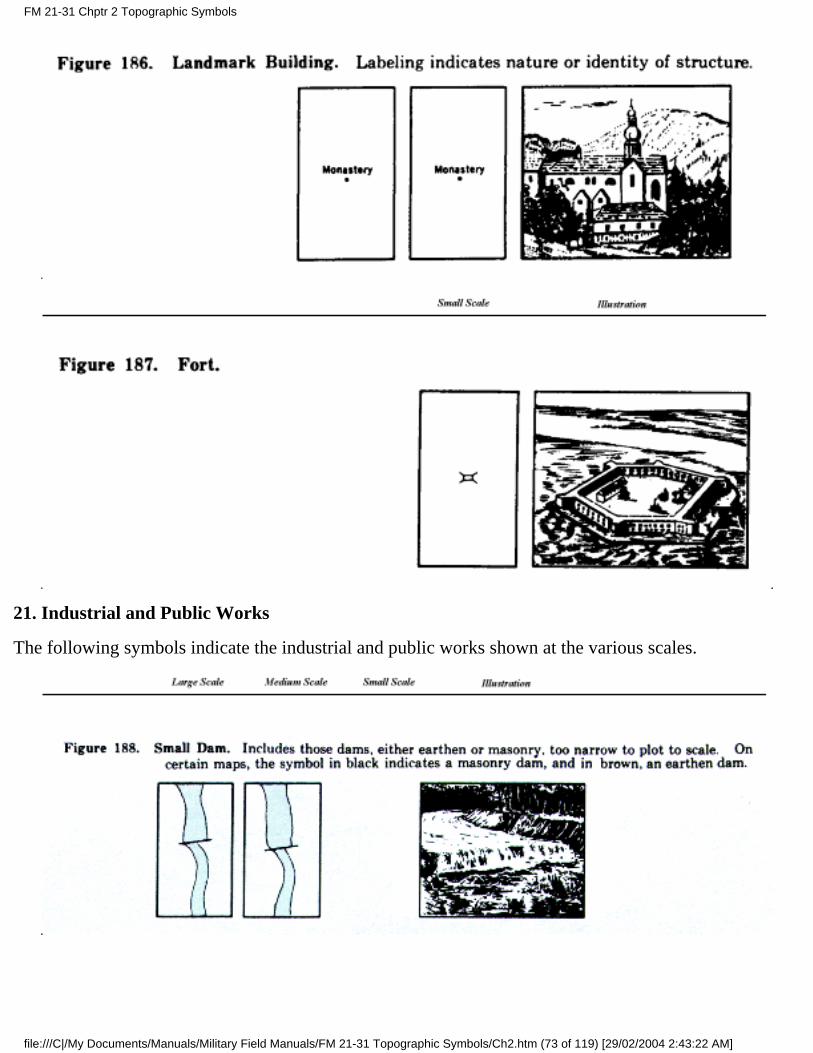
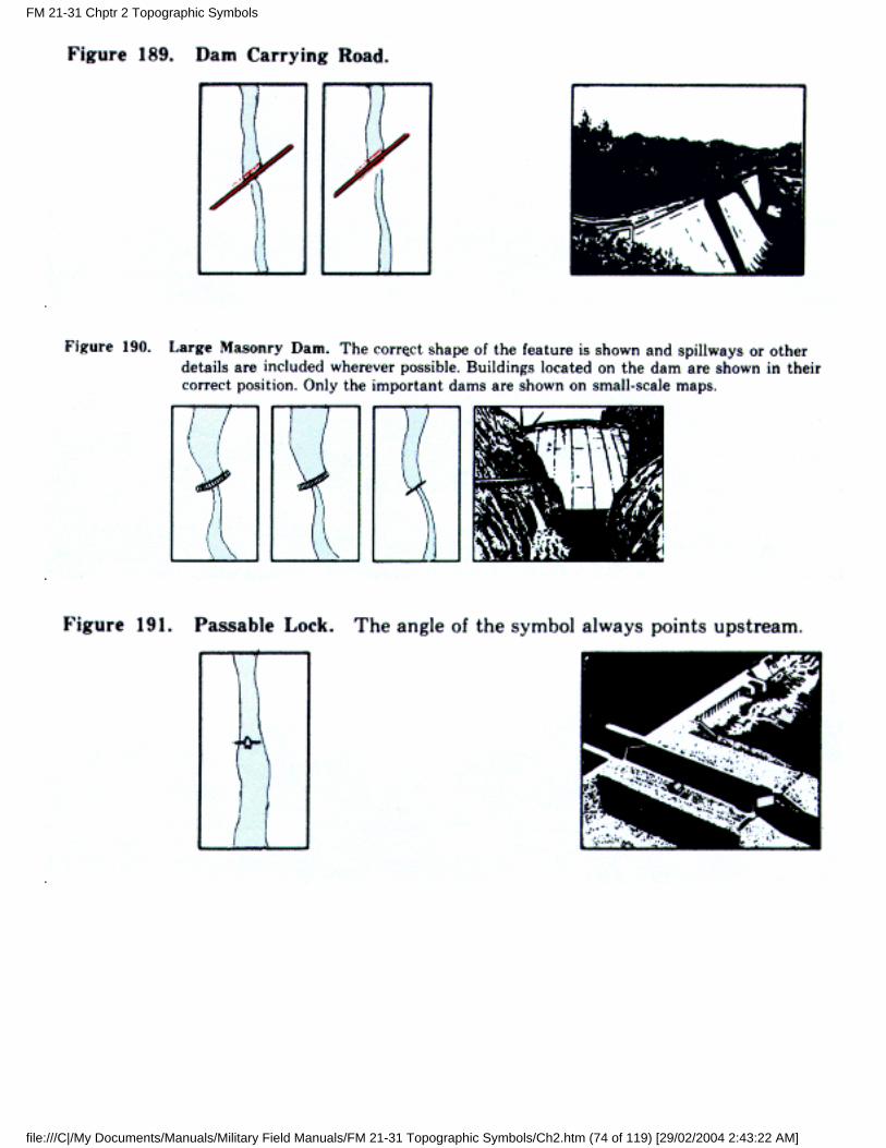
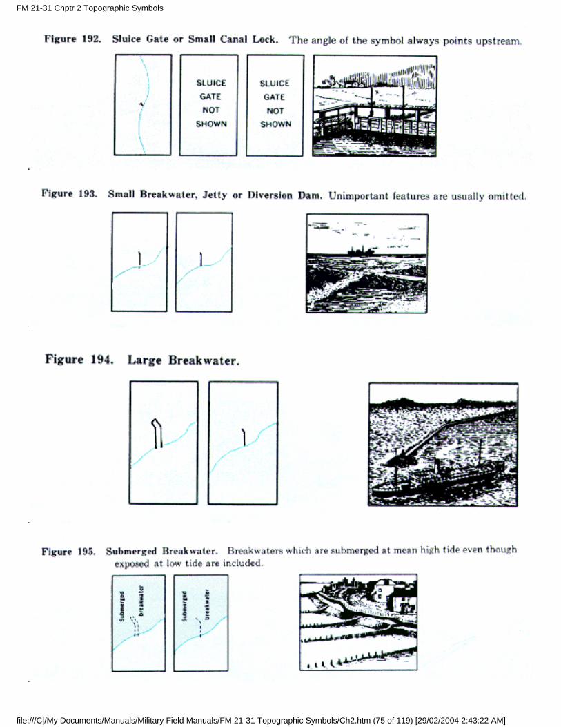
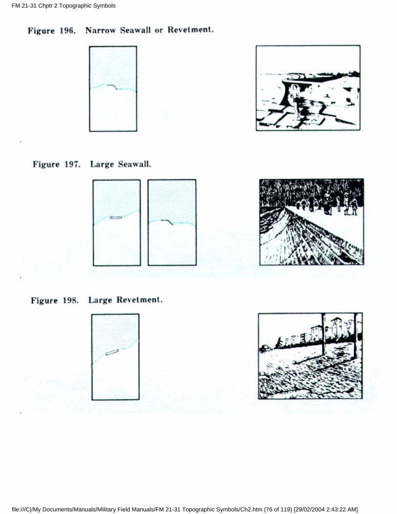
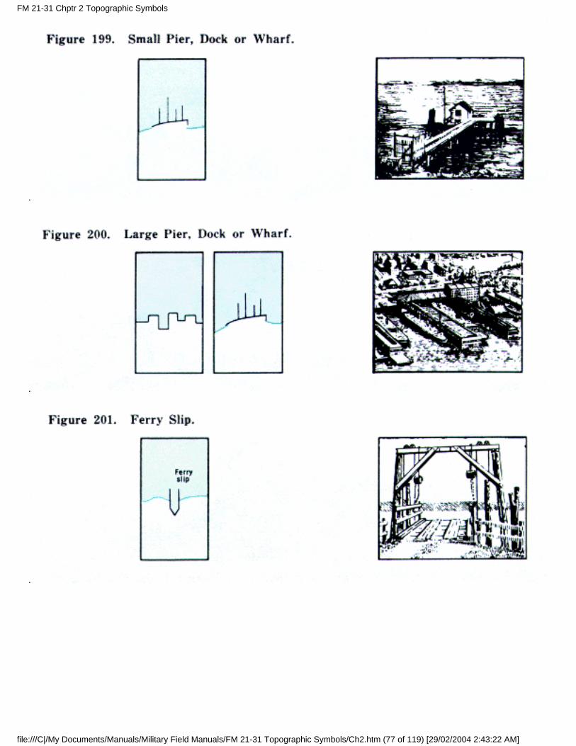
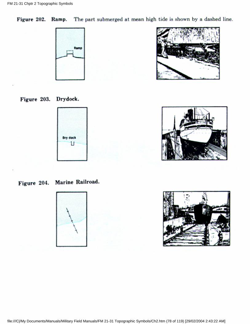
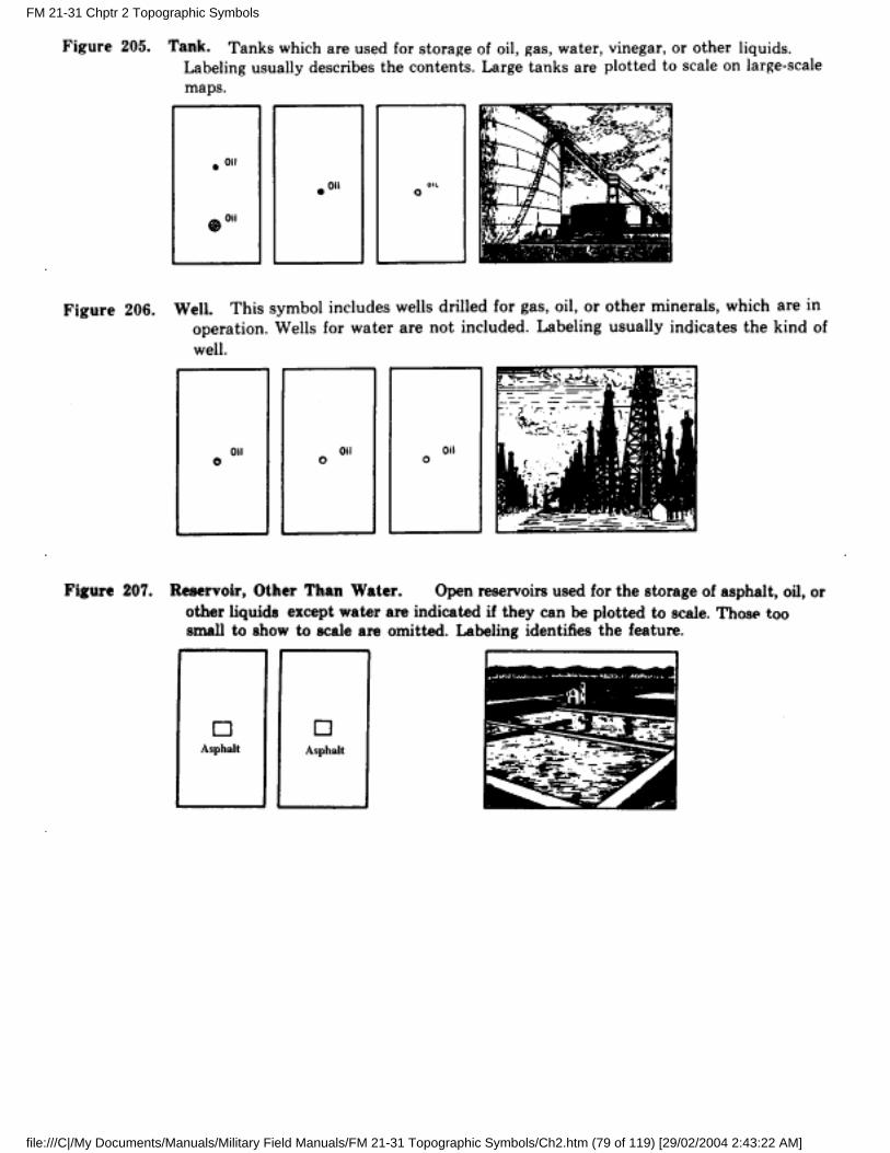
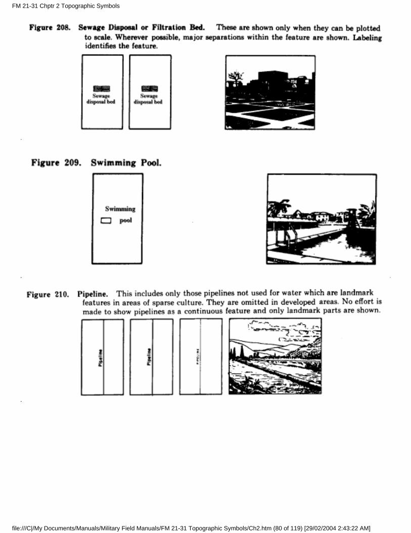
21. Industrial and Public Works
The following symbols indicate the industrial and public works shown at the various scales.
FM 21-31 Chptr 2 Topographic Symbols
file:///C|/My Documents/Manuals/Military Field Manuals/FM 21-31 Topographic Symbols/Ch2.htm (73 of 119) [29/02/2004 2:43:22 AM]
FM 21-31 Chptr 2 Topographic Symbols
file:///C|/My Documents/Manuals/Military Field Manuals/FM 21-31 Topographic Symbols/Ch2.htm (74 of 119) [29/02/2004 2:43:22 AM]
FM 21-31 Chptr 2 Topographic Symbols
file:///C|/My Documents/Manuals/Military Field Manuals/FM 21-31 Topographic Symbols/Ch2.htm (75 of 119) [29/02/2004 2:43:22 AM]
FM 21-31 Chptr 2 Topographic Symbols
file:///C|/My Documents/Manuals/Military Field Manuals/FM 21-31 Topographic Symbols/Ch2.htm (76 of 119) [29/02/2004 2:43:22 AM]
FM 21-31 Chptr 2 Topographic Symbols
file:///C|/My Documents/Manuals/Military Field Manuals/FM 21-31 Topographic Symbols/Ch2.htm (77 of 119) [29/02/2004 2:43:22 AM]
FM 21-31 Chptr 2 Topographic Symbols
file:///C|/My Documents/Manuals/Military Field Manuals/FM 21-31 Topographic Symbols/Ch2.htm (78 of 119) [29/02/2004 2:43:22 AM]
FM 21-31 Chptr 2 Topographic Symbols
file:///C|/My Documents/Manuals/Military Field Manuals/FM 21-31 Topographic Symbols/Ch2.htm (79 of 119) [29/02/2004 2:43:22 AM]
FM 21-31 Chptr 2 Topographic Symbols
file:///C|/My Documents/Manuals/Military Field Manuals/FM 21-31 Topographic Symbols/Ch2.htm (80 of 119) [29/02/2004 2:43:22 AM]
FM 21-31 Chptr 2 Topographic Symbols
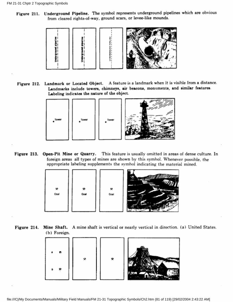
file:///C|/My Documents/Manuals/Military Field Manuals/FM 21-31 Topographic Symbols/Ch2.htm (81 of 119) [29/02/2004 2:43:22 AM]
FM 21-31 Chptr 2 Topographic Symbols
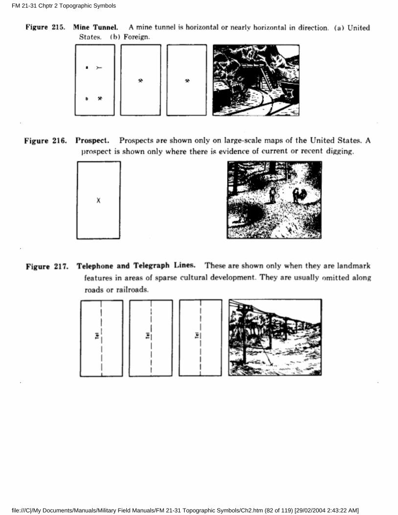
file:///C|/My Documents/Manuals/Military Field Manuals/FM 21-31 Topographic Symbols/Ch2.htm (82 of 119) [29/02/2004 2:43:22 AM]
FM 21-31 Chptr 2 Topographic Symbols
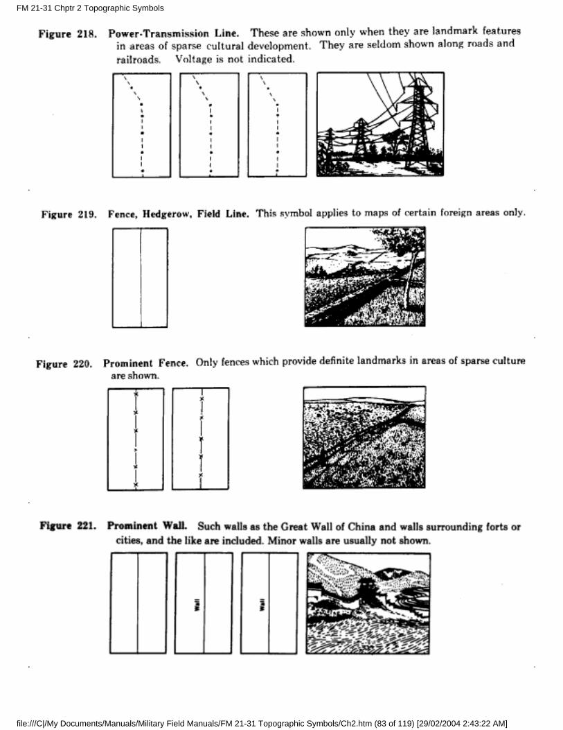
file:///C|/My Documents/Manuals/Military Field Manuals/FM 21-31 Topographic Symbols/Ch2.htm (83 of 119) [29/02/2004 2:43:22 AM]
FM 21-31 Chptr 2 Topographic Symbols
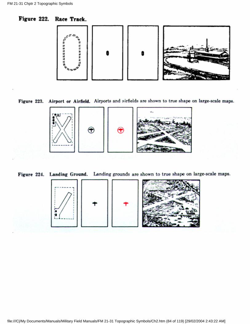
file:///C|/My Documents/Manuals/Military Field Manuals/FM 21-31 Topographic Symbols/Ch2.htm (84 of 119) [29/02/2004 2:43:22 AM]
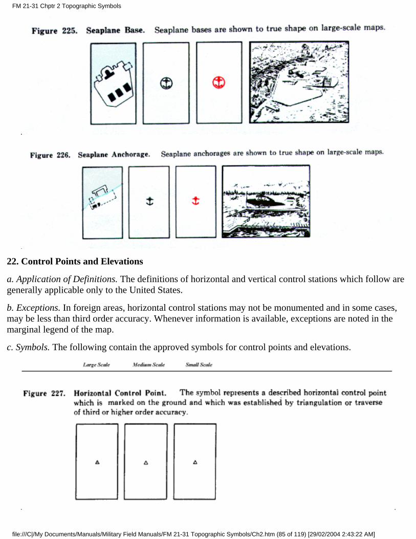
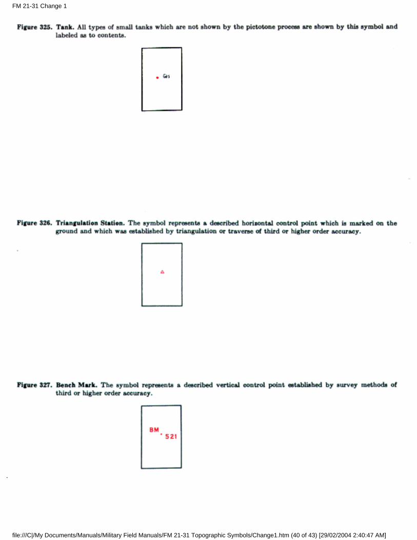
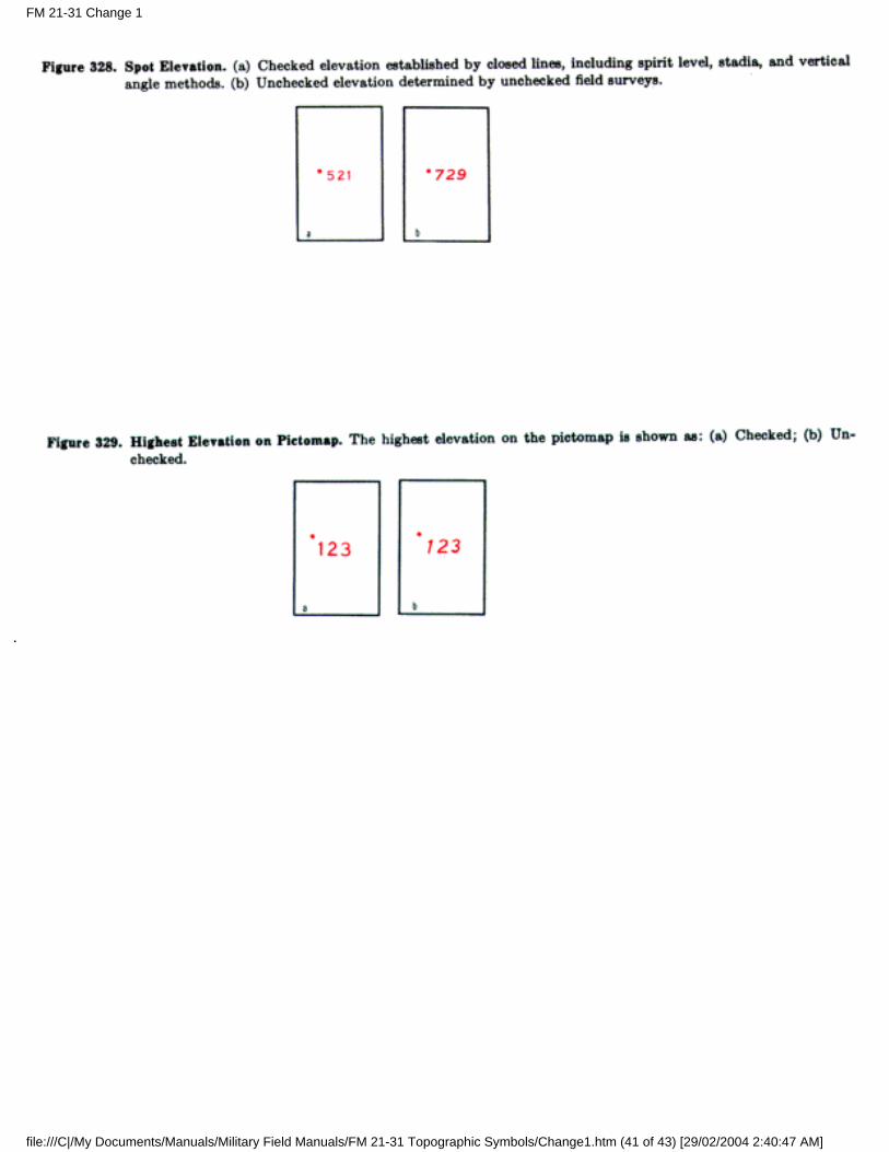
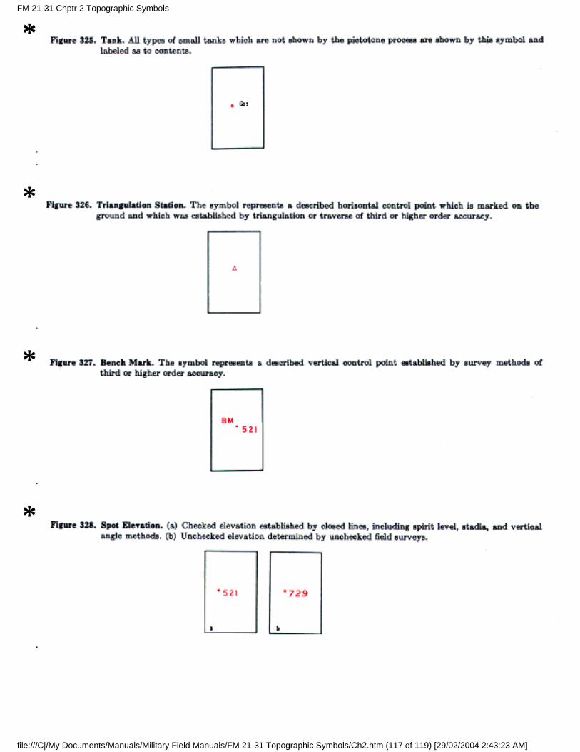
22. Control Points and Elevations
a. Application of Definitions. The definitions of horizontal and vertical control stations which follow aregenerally applicable only to the United States.
b. Exceptions. In foreign areas, horizontal control stations may not be monumented and in some cases,may be less than third order accuracy. Whenever information is available, exceptions are noted in themarginal legend of the map.
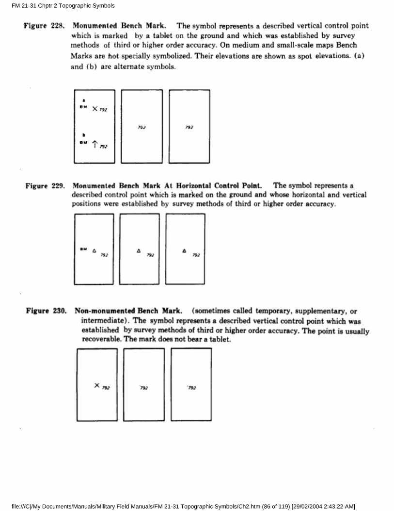
c. Symbols. The following contain the approved symbols for control points and elevations.
FM 21-31 Chptr 2 Topographic Symbols
file:///C|/My Documents/Manuals/Military Field Manuals/FM 21-31 Topographic Symbols/Ch2.htm (85 of 119) [29/02/2004 2:43:22 AM]
FM 21-31 Chptr 2 Topographic Symbols
file:///C|/My Documents/Manuals/Military Field Manuals/FM 21-31 Topographic Symbols/Ch2.htm (86 of 119) [29/02/2004 2:43:22 AM]
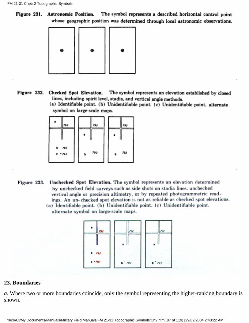
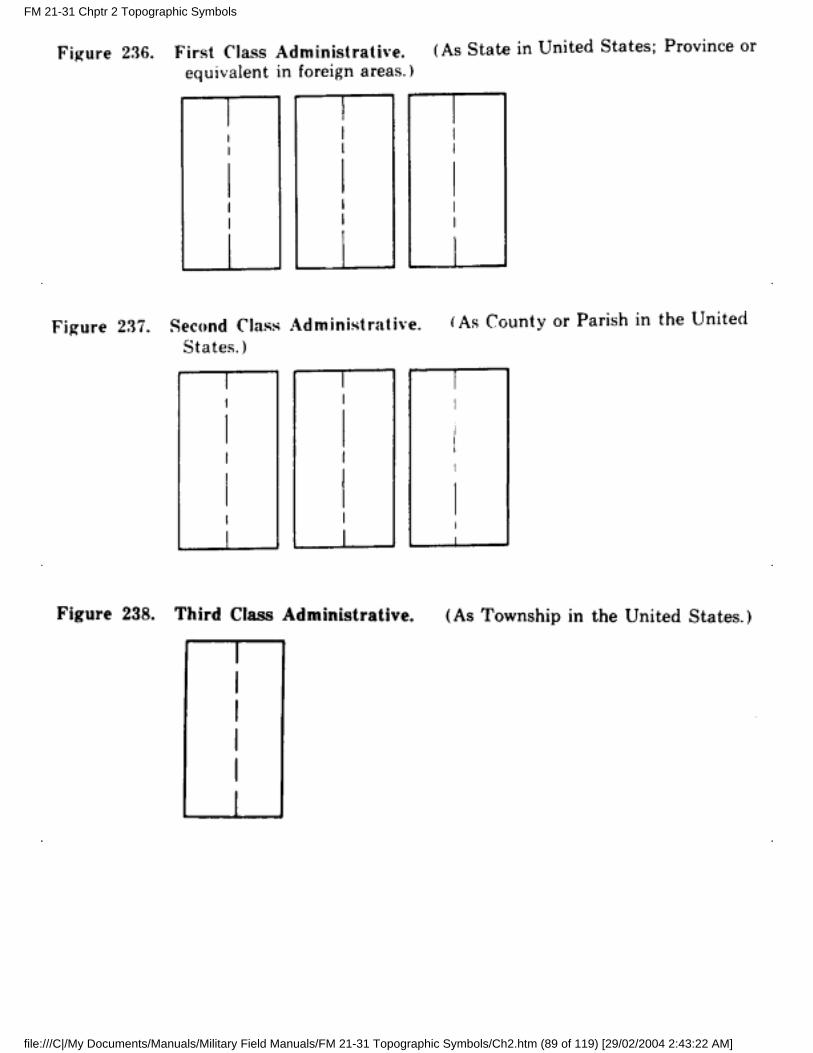
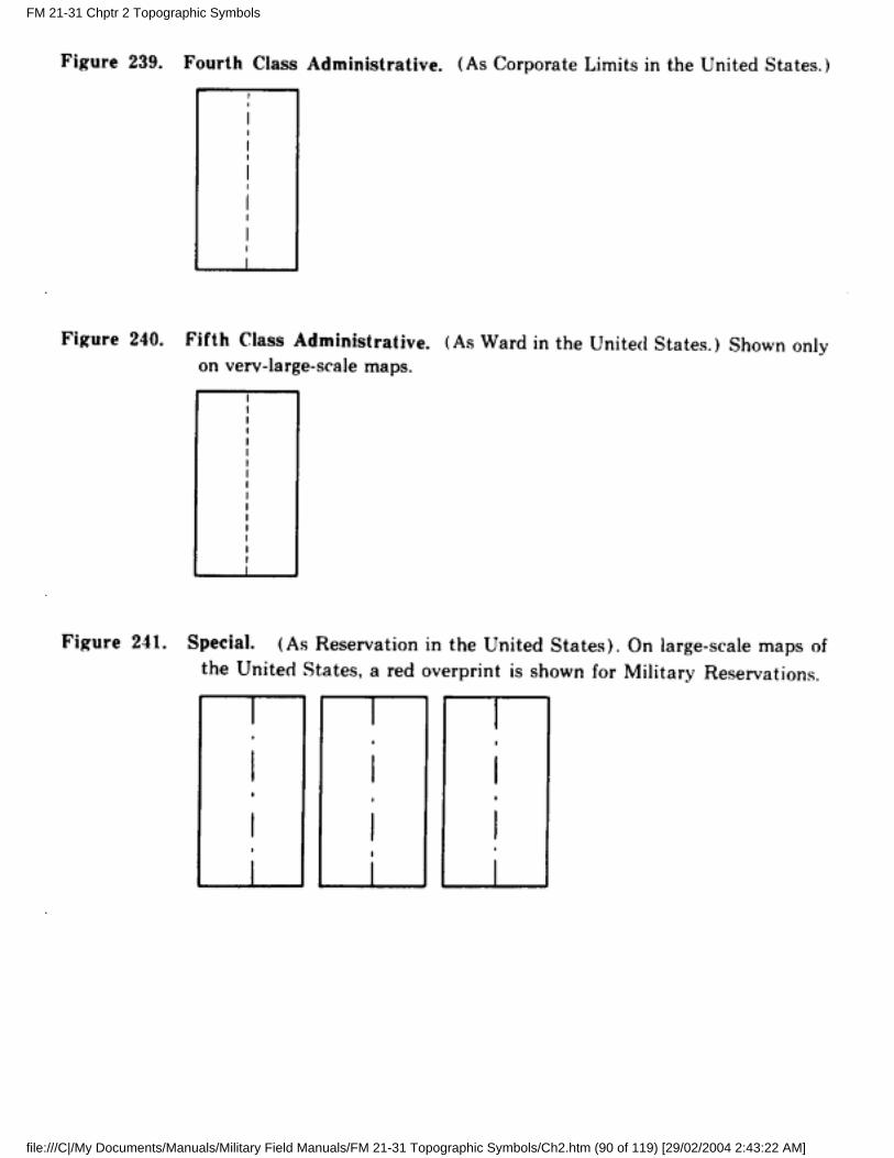
23. Boundaries
a. Where two or more boundaries coincide, only the symbol representing the higher-ranking boundary isshown.
FM 21-31 Chptr 2 Topographic Symbols
file:///C|/My Documents/Manuals/Military Field Manuals/FM 21-31 Topographic Symbols/Ch2.htm (87 of 119) [29/02/2004 2:43:22 AM]
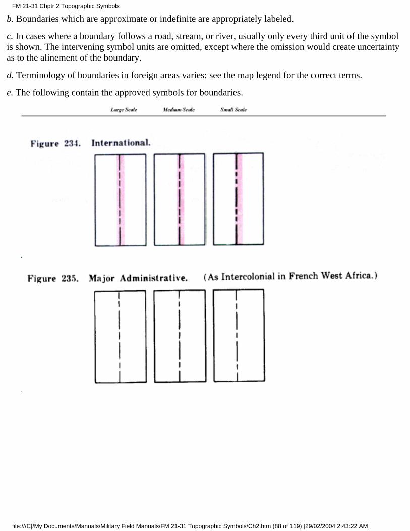
b. Boundaries which are approximate or indefinite are appropriately labeled.
c. In cases where a boundary follows a road, stream, or river, usually only every third unit of the symbolis shown. The intervening symbol units are omitted, except where the omission would create uncertaintyas to the alinement of the boundary.
d. Terminology of boundaries in foreign areas varies; see the map legend for the correct terms.
e. The following contain the approved symbols for boundaries.
FM 21-31 Chptr 2 Topographic Symbols
file:///C|/My Documents/Manuals/Military Field Manuals/FM 21-31 Topographic Symbols/Ch2.htm (88 of 119) [29/02/2004 2:43:22 AM]
FM 21-31 Chptr 2 Topographic Symbols
file:///C|/My Documents/Manuals/Military Field Manuals/FM 21-31 Topographic Symbols/Ch2.htm (89 of 119) [29/02/2004 2:43:22 AM]
FM 21-31 Chptr 2 Topographic Symbols
file:///C|/My Documents/Manuals/Military Field Manuals/FM 21-31 Topographic Symbols/Ch2.htm (90 of 119) [29/02/2004 2:43:22 AM]
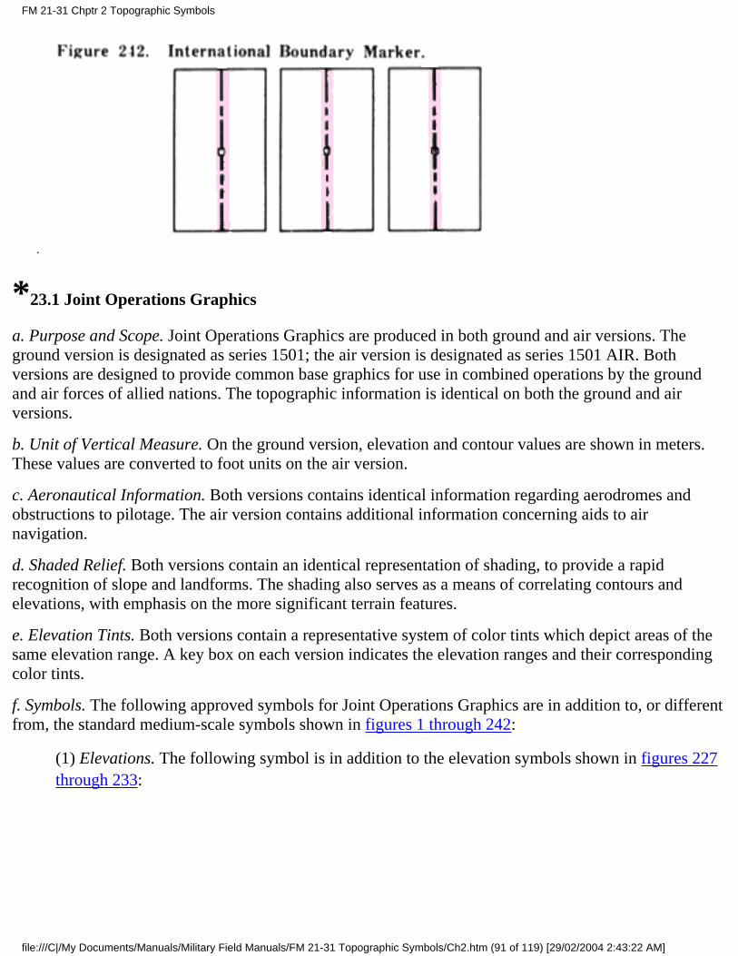
*23.1 Joint Operations Graphics
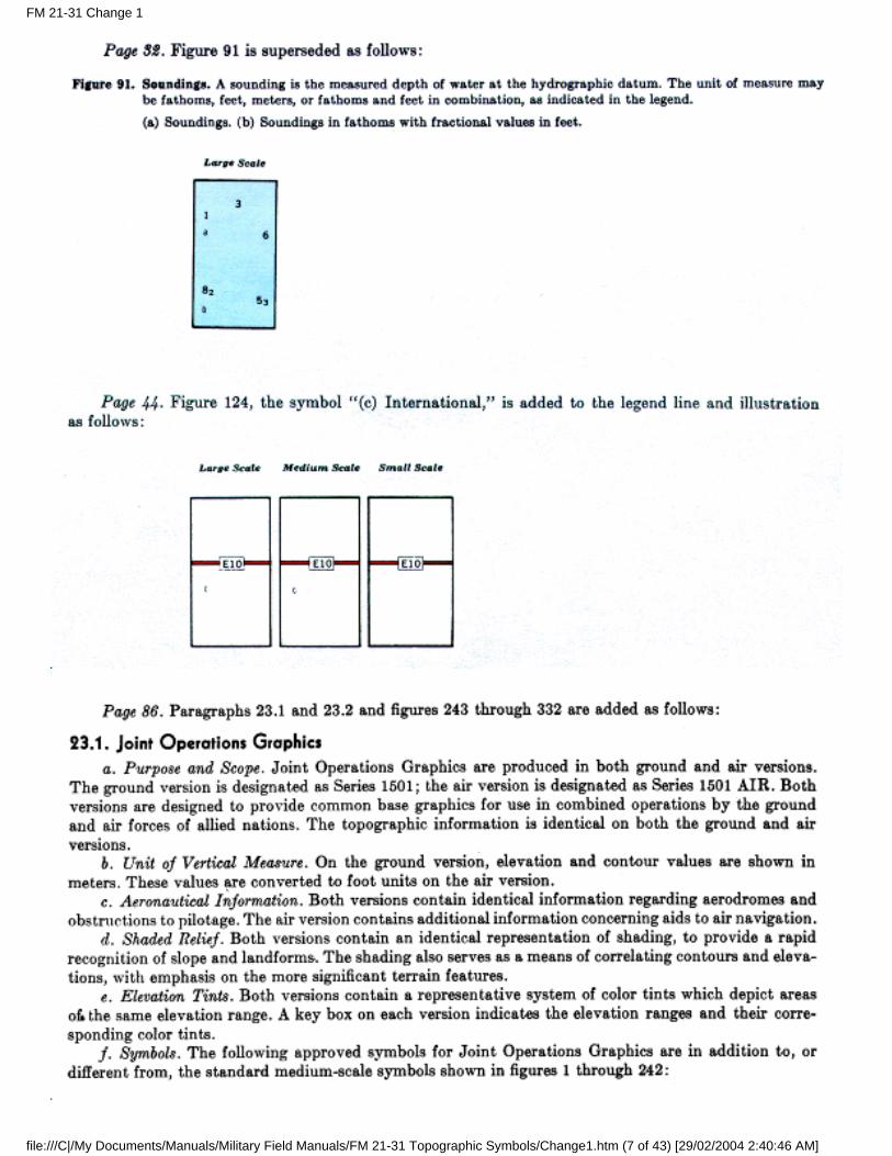
a. Purpose and Scope. Joint Operations Graphics are produced in both ground and air versions. Theground version is designated as series 1501; the air version is designated as series 1501 AIR. Bothversions are designed to provide common base graphics for use in combined operations by the groundand air forces of allied nations. The topographic information is identical on both the ground and airversions.
b. Unit of Vertical Measure. On the ground version, elevation and contour values are shown in meters.These values are converted to foot units on the air version.
c. Aeronautical Information. Both versions contains identical information regarding aerodromes andobstructions to pilotage. The air version contains additional information concerning aids to airnavigation.
d. Shaded Relief. Both versions contain an identical representation of shading, to provide a rapidrecognition of slope and landforms. The shading also serves as a means of correlating contours andelevations, with emphasis on the more significant terrain features.
e. Elevation Tints. Both versions contain a representative system of color tints which depict areas of thesame elevation range. A key box on each version indicates the elevation ranges and their correspondingcolor tints.
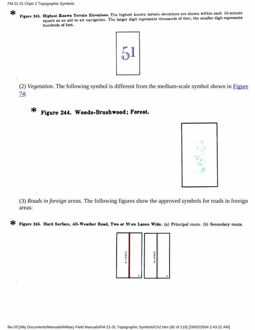
f. Symbols. The following approved symbols for Joint Operations Graphics are in addition to, or differentfrom, the standard medium-scale symbols shown in figures 1 through 242:
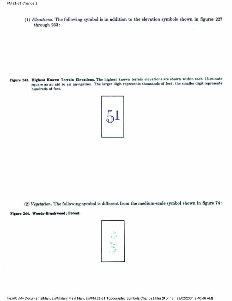
(1) Elevations. The following symbol is in addition to the elevation symbols shown in figures 227through 233:
FM 21-31 Chptr 2 Topographic Symbols
file:///C|/My Documents/Manuals/Military Field Manuals/FM 21-31 Topographic Symbols/Ch2.htm (91 of 119) [29/02/2004 2:43:22 AM]
*
(2) Vegetation. The following symbol is different from the medium-scale symbol shown in Figure74:
*
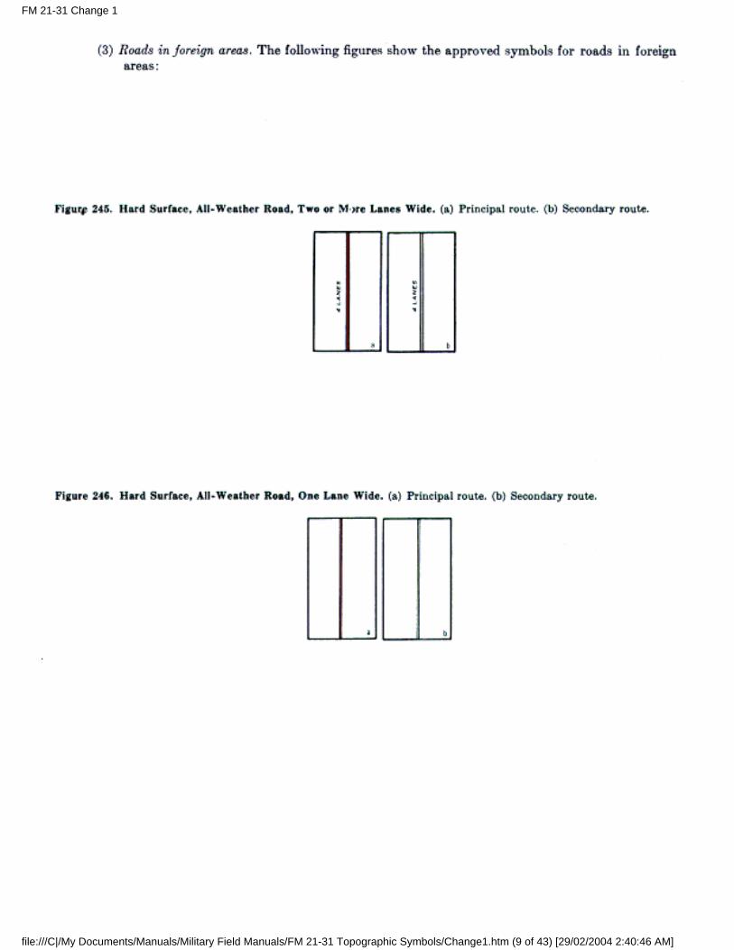
(3) Roads in foreign areas. The following figures show the approved symbols for roads in foreignareas:
*
FM 21-31 Chptr 2 Topographic Symbols
file:///C|/My Documents/Manuals/Military Field Manuals/FM 21-31 Topographic Symbols/Ch2.htm (92 of 119) [29/02/2004 2:43:22 AM]
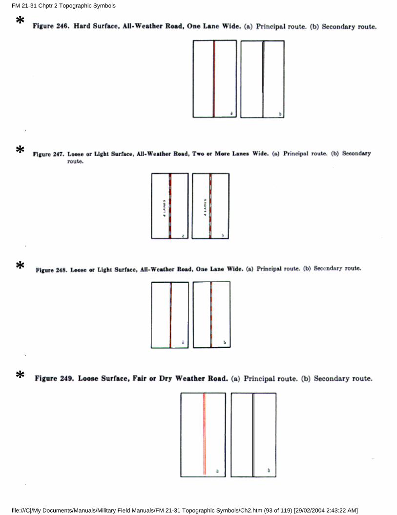
*
*
*
*
FM 21-31 Chptr 2 Topographic Symbols
file:///C|/My Documents/Manuals/Military Field Manuals/FM 21-31 Topographic Symbols/Ch2.htm (93 of 119) [29/02/2004 2:43:22 AM]
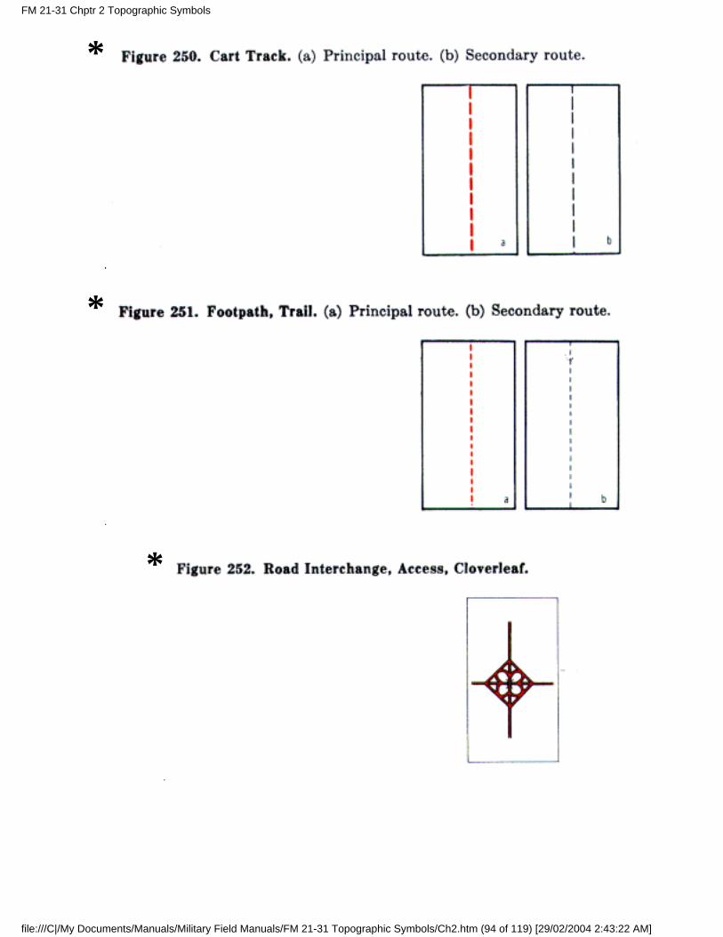
*
*
*
FM 21-31 Chptr 2 Topographic Symbols
file:///C|/My Documents/Manuals/Military Field Manuals/FM 21-31 Topographic Symbols/Ch2.htm (94 of 119) [29/02/2004 2:43:22 AM]
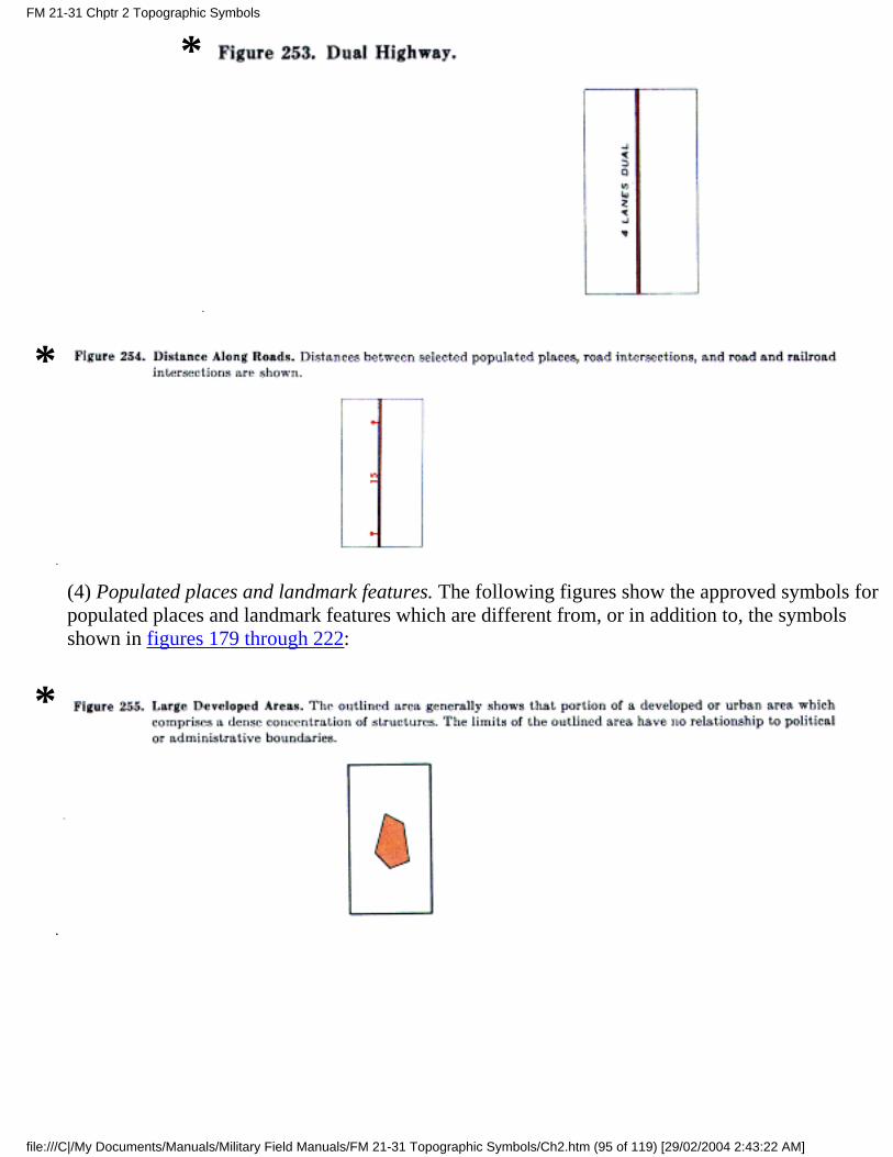
*
*
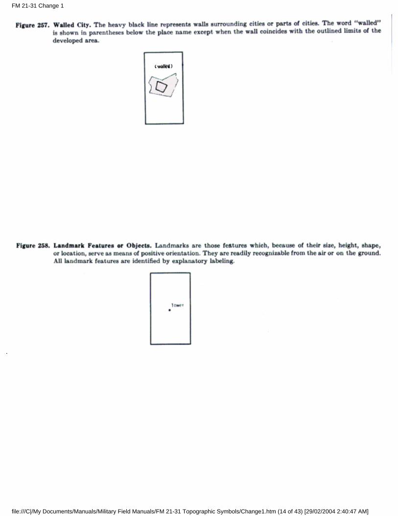
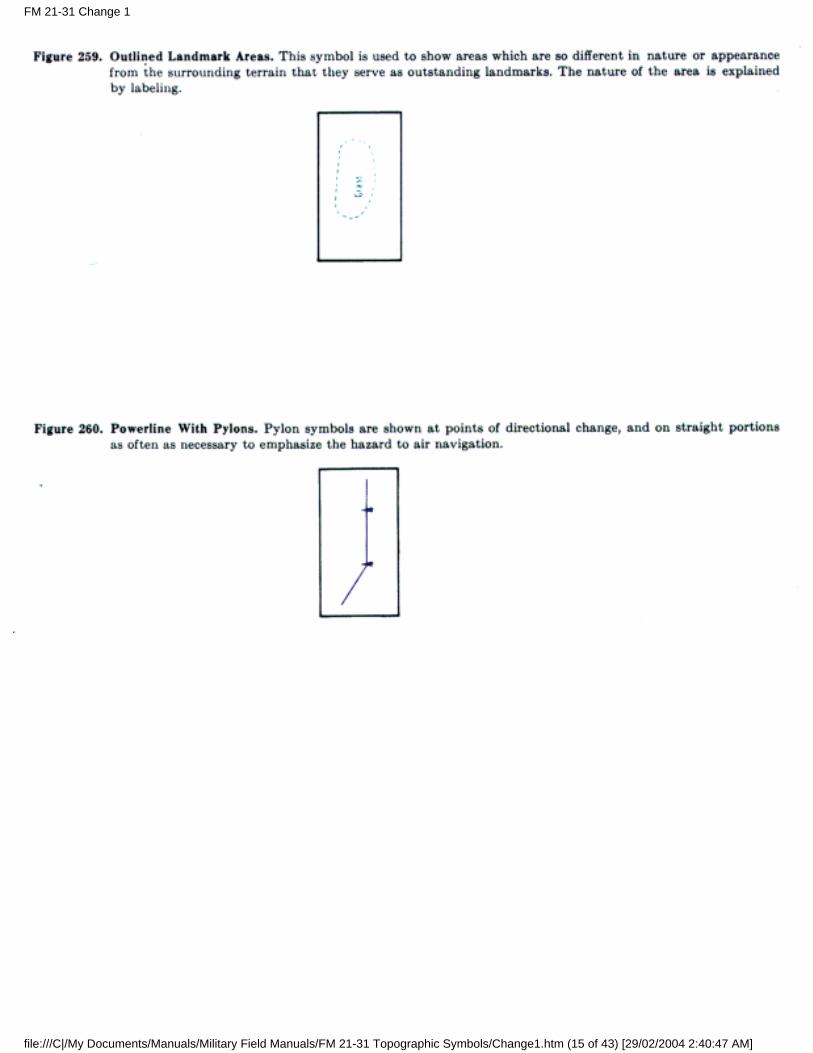
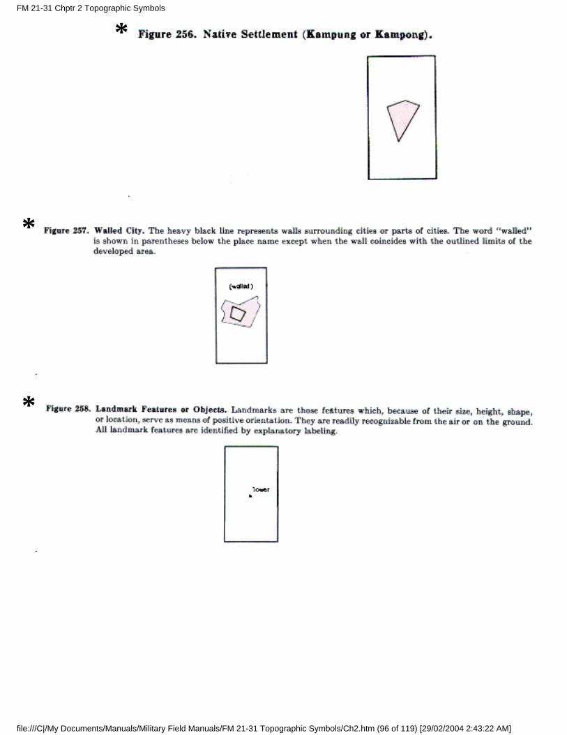
(4) Populated places and landmark features. The following figures show the approved symbols forpopulated places and landmark features which are different from, or in addition to, the symbolsshown in figures 179 through 222:
*
FM 21-31 Chptr 2 Topographic Symbols
file:///C|/My Documents/Manuals/Military Field Manuals/FM 21-31 Topographic Symbols/Ch2.htm (95 of 119) [29/02/2004 2:43:22 AM]
*
*
*
FM 21-31 Chptr 2 Topographic Symbols
file:///C|/My Documents/Manuals/Military Field Manuals/FM 21-31 Topographic Symbols/Ch2.htm (96 of 119) [29/02/2004 2:43:22 AM]
*
*
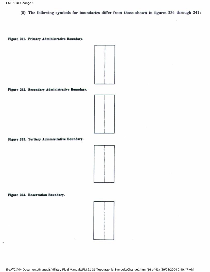
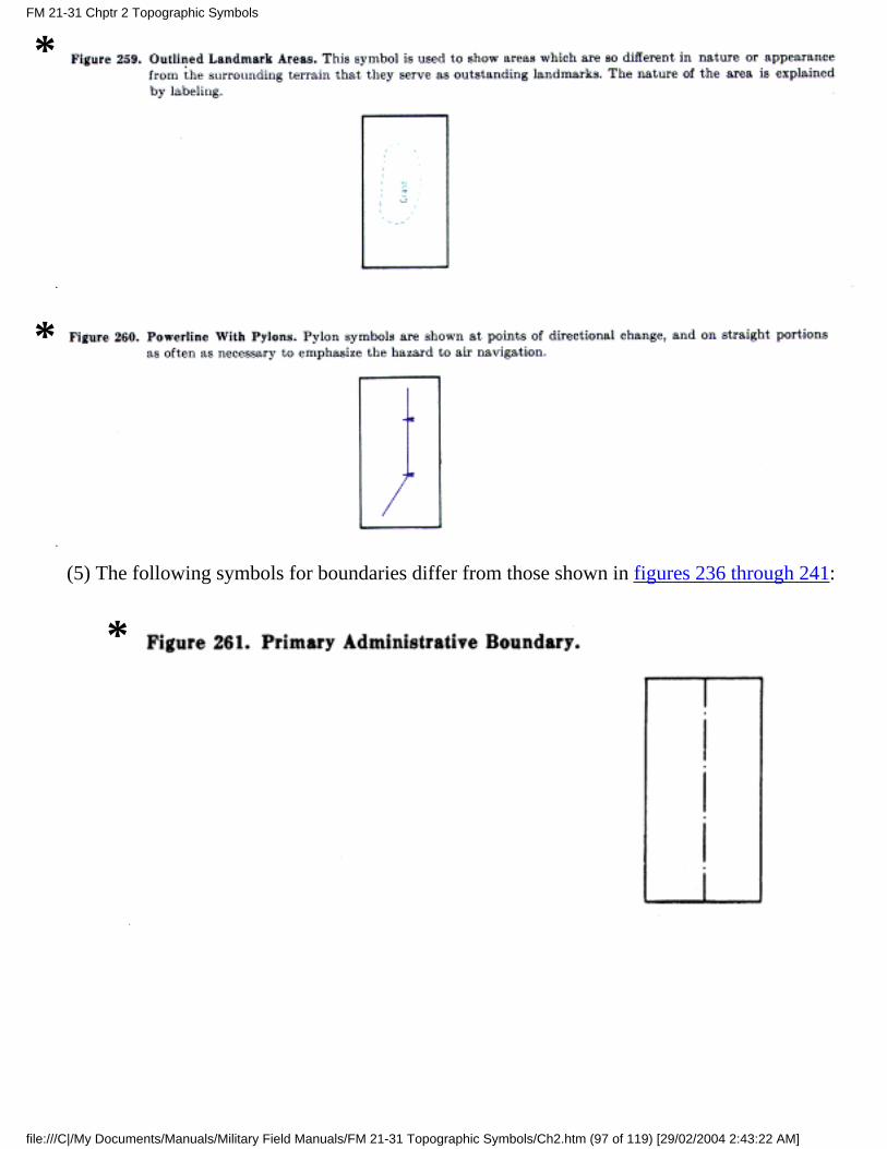
(5) The following symbols for boundaries differ from those shown in figures 236 through 241:
*
FM 21-31 Chptr 2 Topographic Symbols
file:///C|/My Documents/Manuals/Military Field Manuals/FM 21-31 Topographic Symbols/Ch2.htm (97 of 119) [29/02/2004 2:43:22 AM]
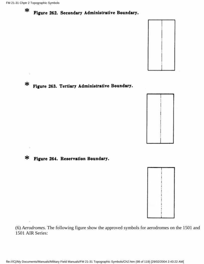
*
*
*
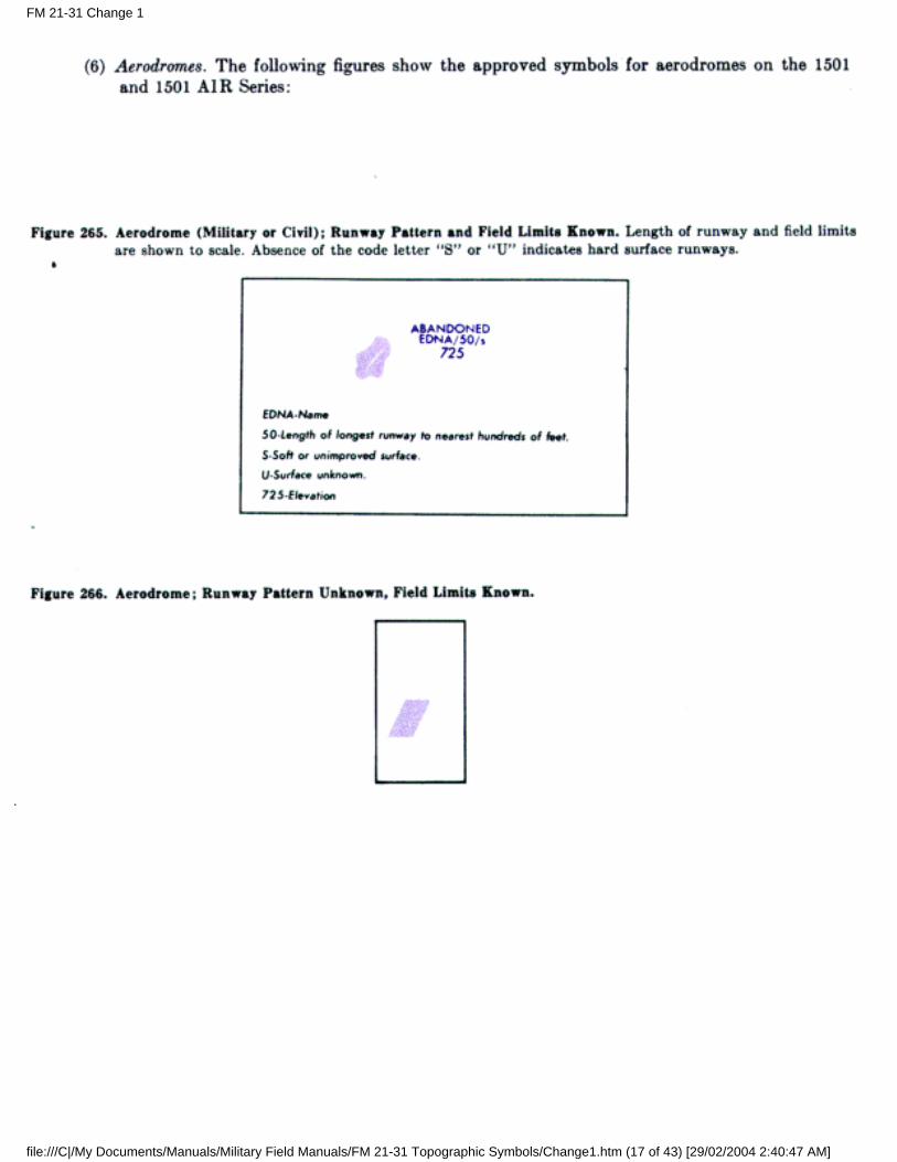
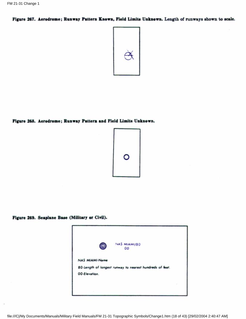
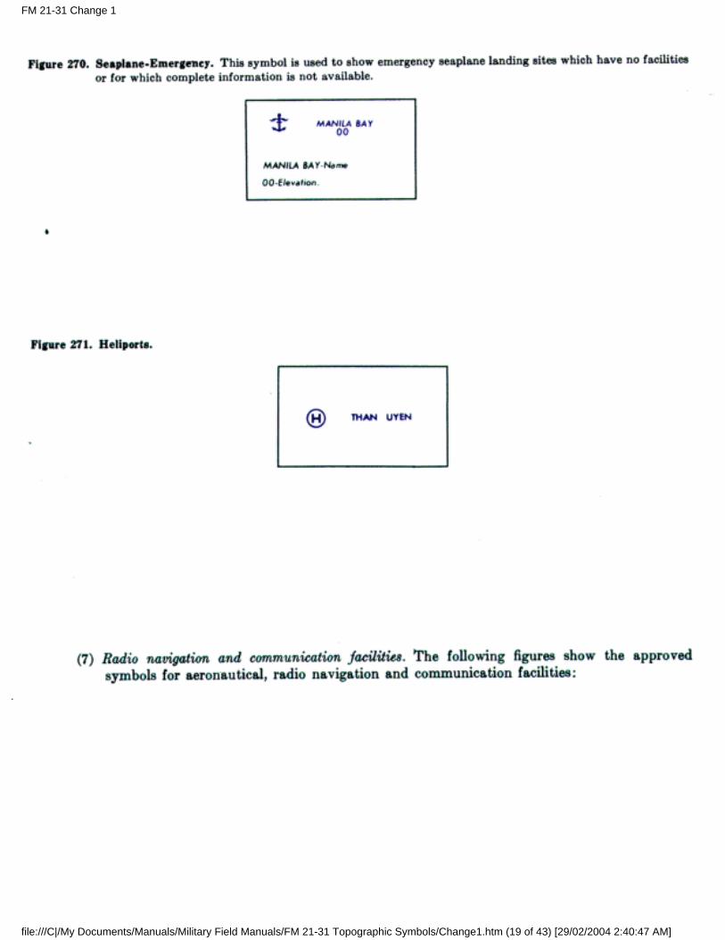
(6) Aerodromes. The following figure show the approved symbols for aerodromes on the 1501 and1501 AIR Series:
FM 21-31 Chptr 2 Topographic Symbols
file:///C|/My Documents/Manuals/Military Field Manuals/FM 21-31 Topographic Symbols/Ch2.htm (98 of 119) [29/02/2004 2:43:22 AM]
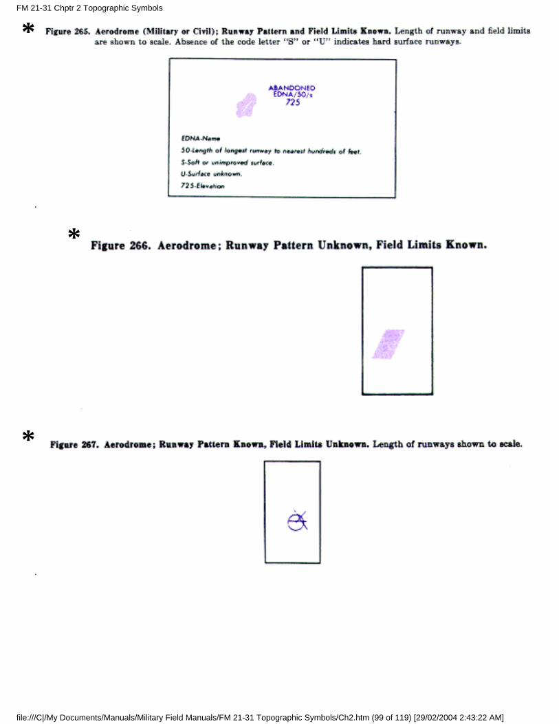
*
*
*
FM 21-31 Chptr 2 Topographic Symbols
file:///C|/My Documents/Manuals/Military Field Manuals/FM 21-31 Topographic Symbols/Ch2.htm (99 of 119) [29/02/2004 2:43:22 AM]
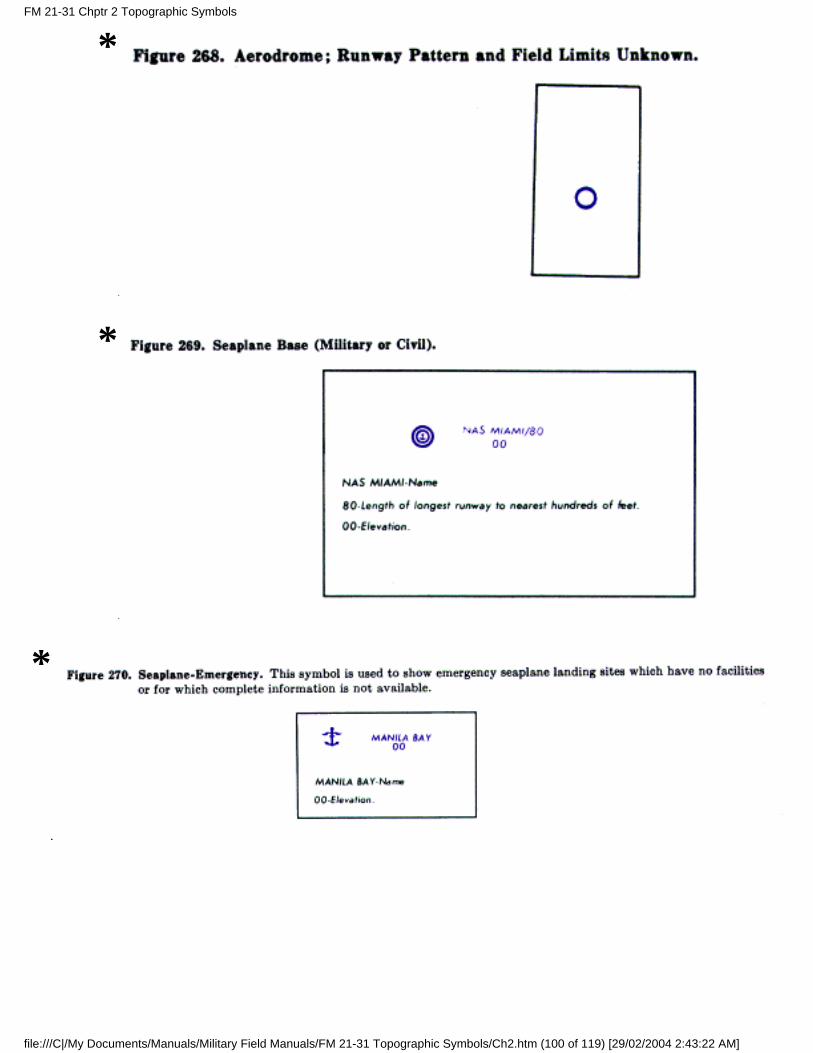
*
*
*
FM 21-31 Chptr 2 Topographic Symbols
file:///C|/My Documents/Manuals/Military Field Manuals/FM 21-31 Topographic Symbols/Ch2.htm (100 of 119) [29/02/2004 2:43:22 AM]
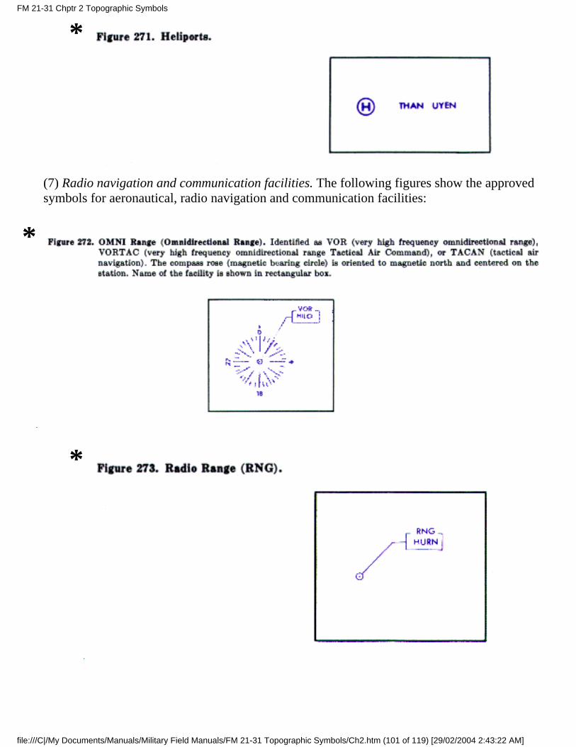
*
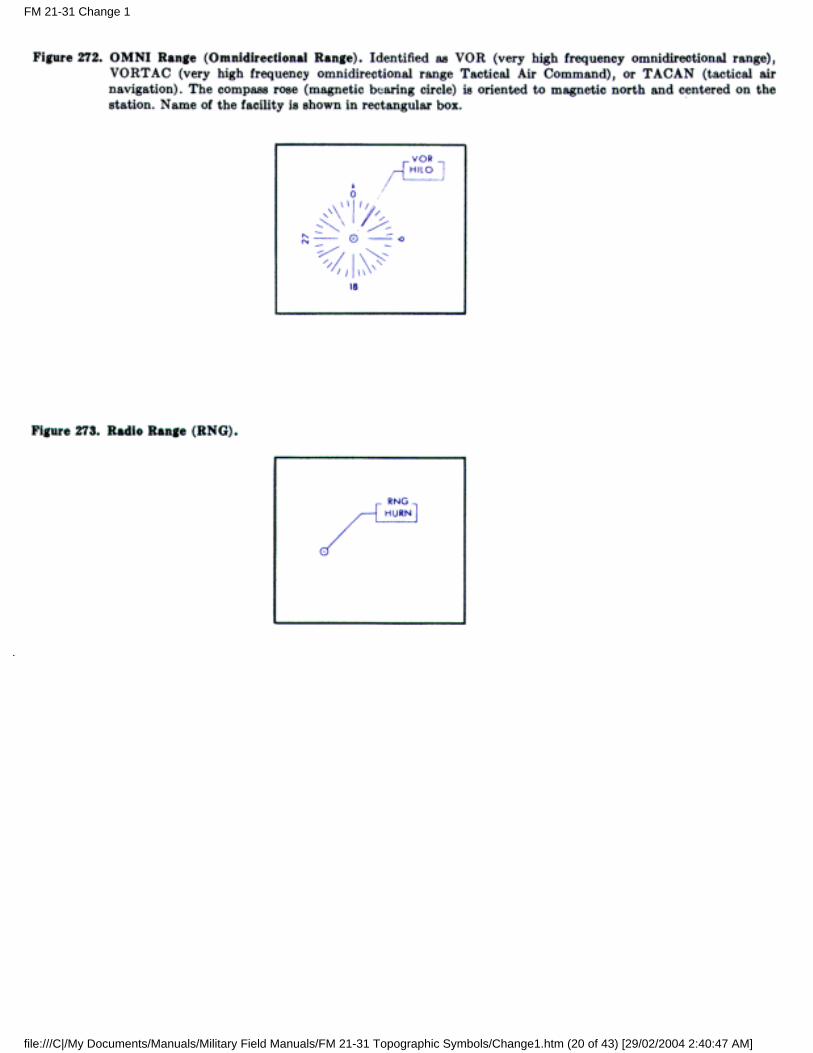
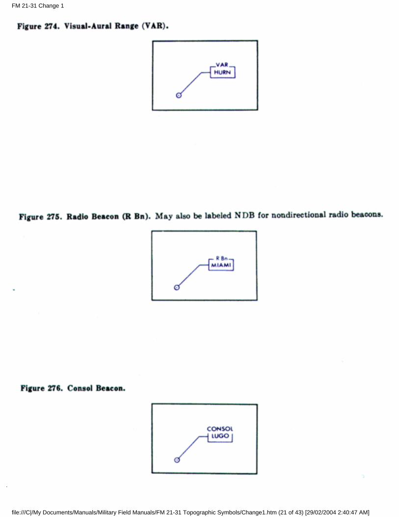
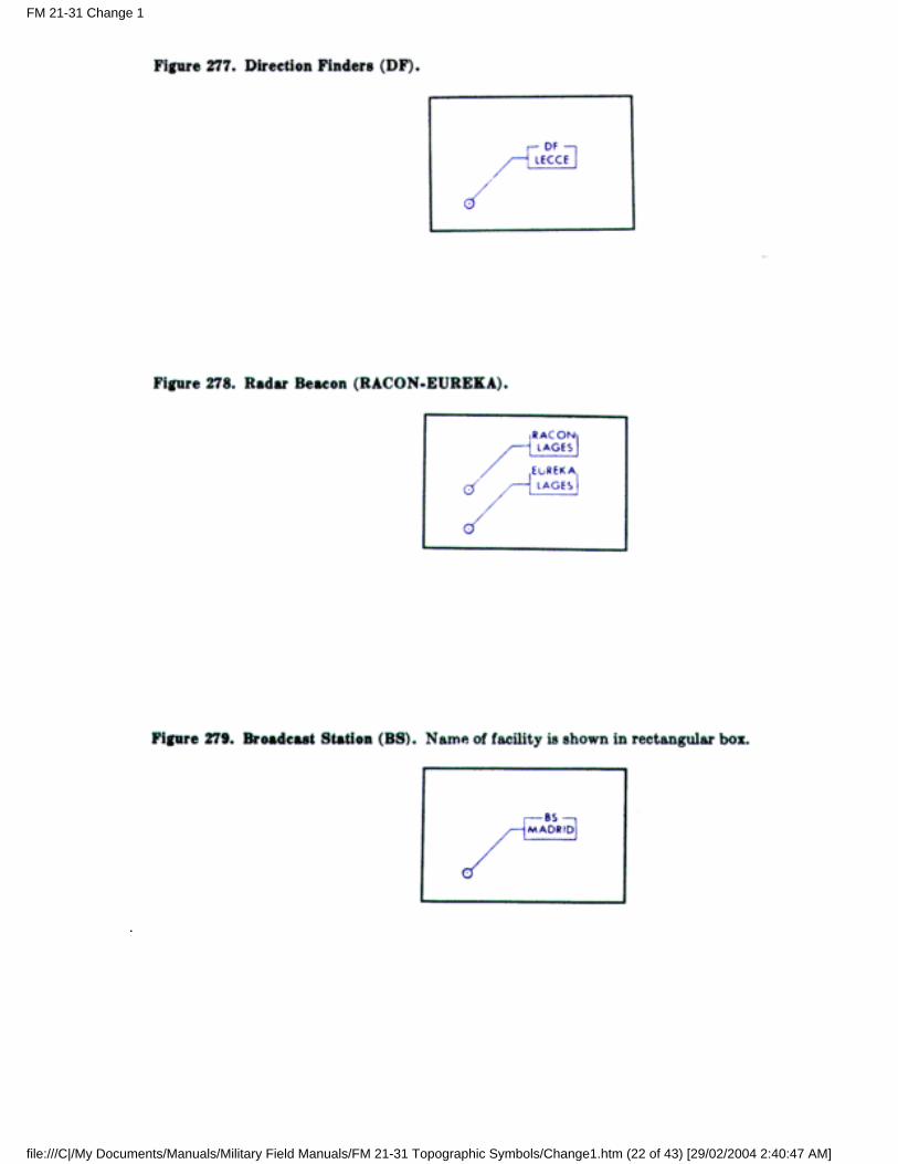
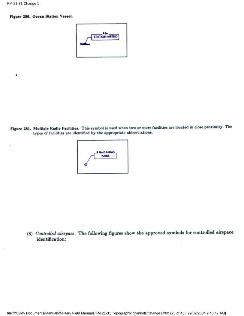
(7) Radio navigation and communication facilities. The following figures show the approvedsymbols for aeronautical, radio navigation and communication facilities:
*
*
FM 21-31 Chptr 2 Topographic Symbols
file:///C|/My Documents/Manuals/Military Field Manuals/FM 21-31 Topographic Symbols/Ch2.htm (101 of 119) [29/02/2004 2:43:22 AM]

*
*
*
*
FM 21-31 Chptr 2 Topographic Symbols
file:///C|/My Documents/Manuals/Military Field Manuals/FM 21-31 Topographic Symbols/Ch2.htm (102 of 119) [29/02/2004 2:43:22 AM]
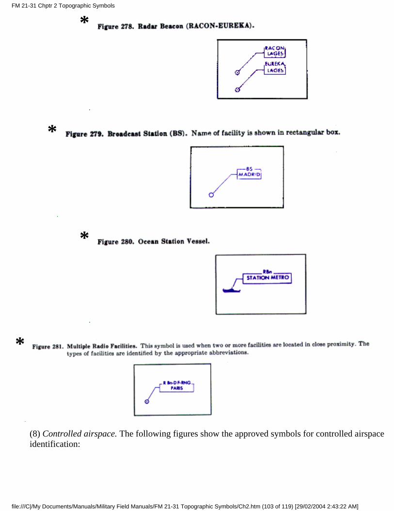
*
*
*
*
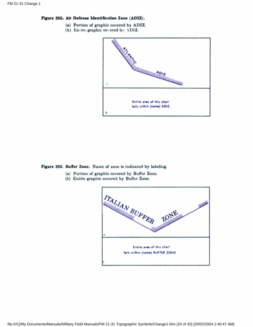
(8) Controlled airspace. The following figures show the approved symbols for controlled airspaceidentification:
FM 21-31 Chptr 2 Topographic Symbols
file:///C|/My Documents/Manuals/Military Field Manuals/FM 21-31 Topographic Symbols/Ch2.htm (103 of 119) [29/02/2004 2:43:22 AM]
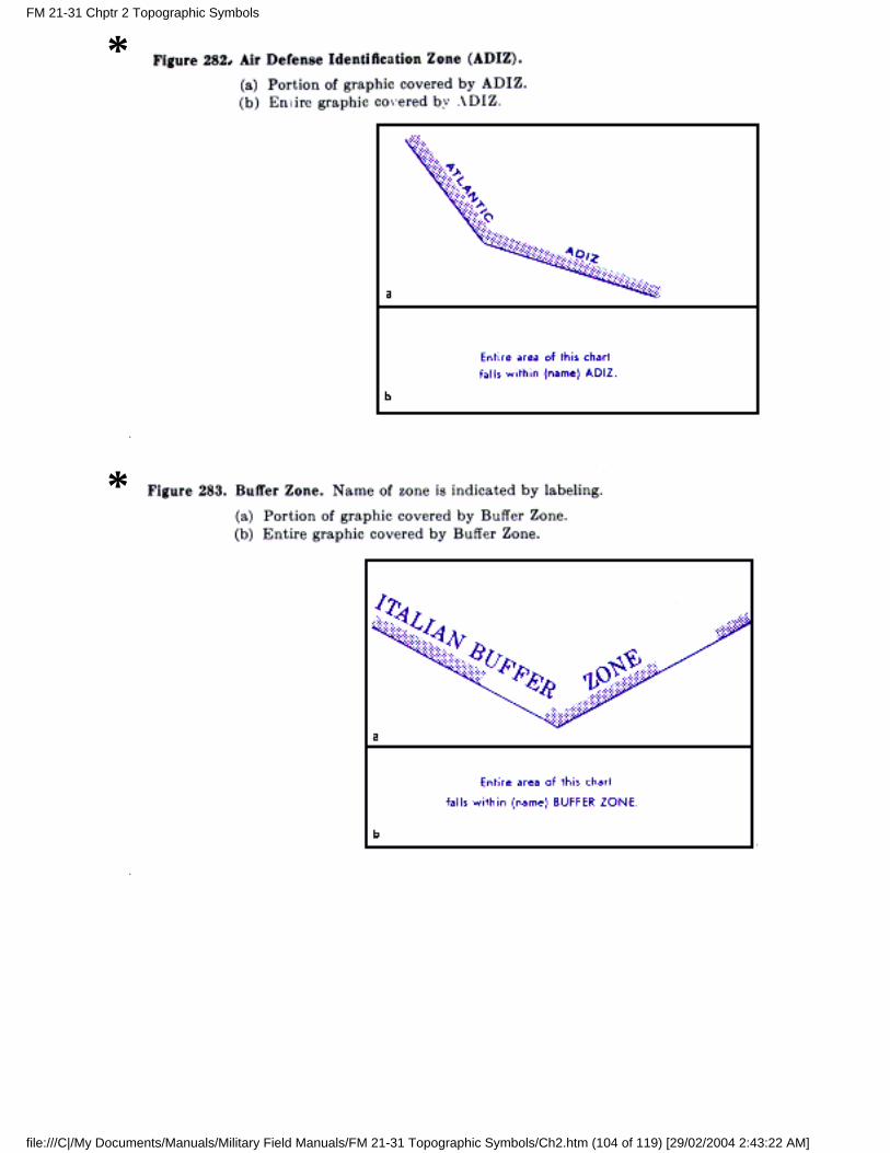
*
*
FM 21-31 Chptr 2 Topographic Symbols
file:///C|/My Documents/Manuals/Military Field Manuals/FM 21-31 Topographic Symbols/Ch2.htm (104 of 119) [29/02/2004 2:43:22 AM]
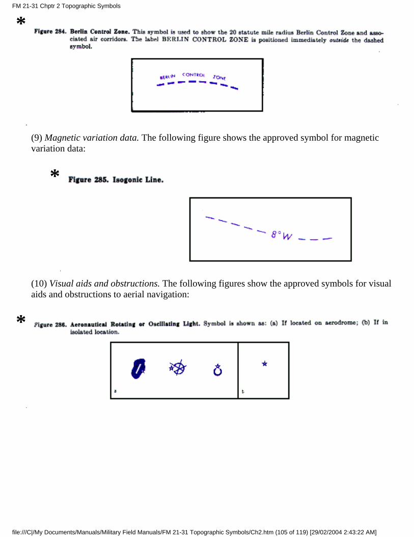
*
(9) Magnetic variation data. The following figure shows the approved symbol for magneticvariation data:
*
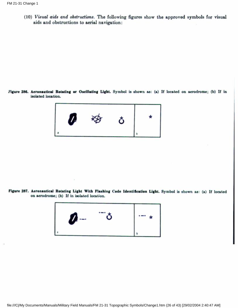
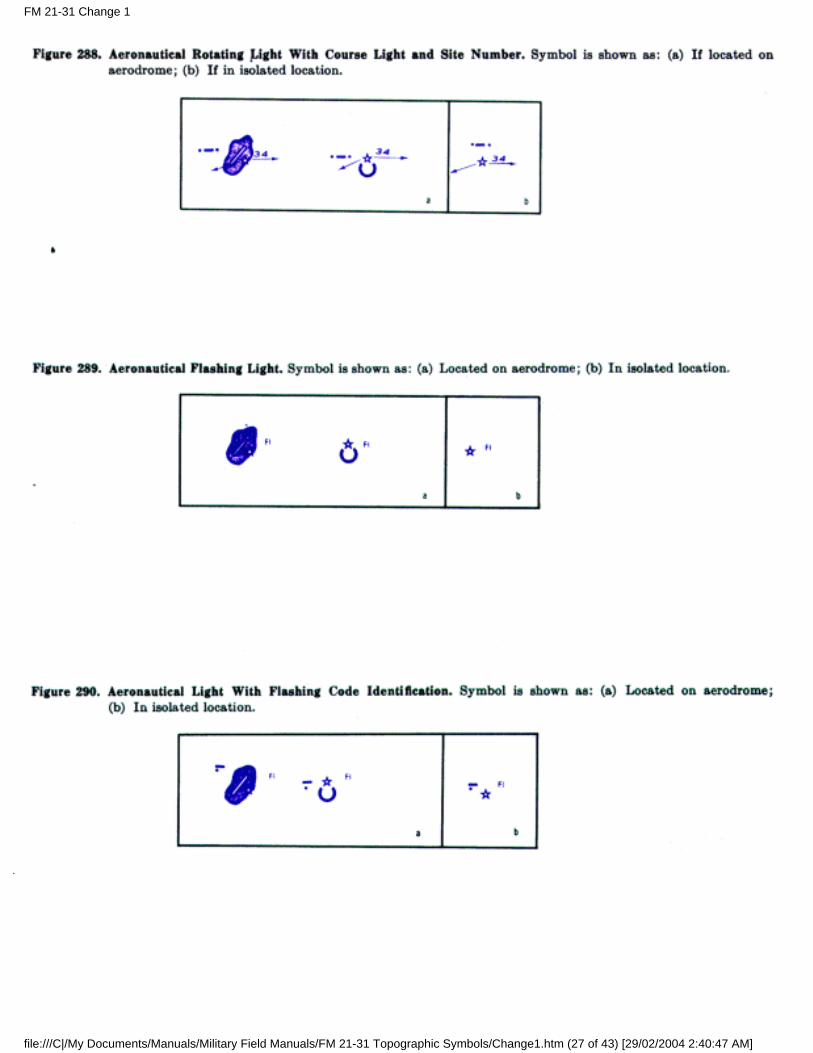
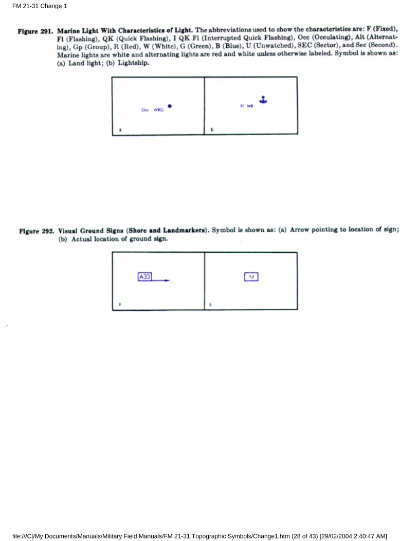
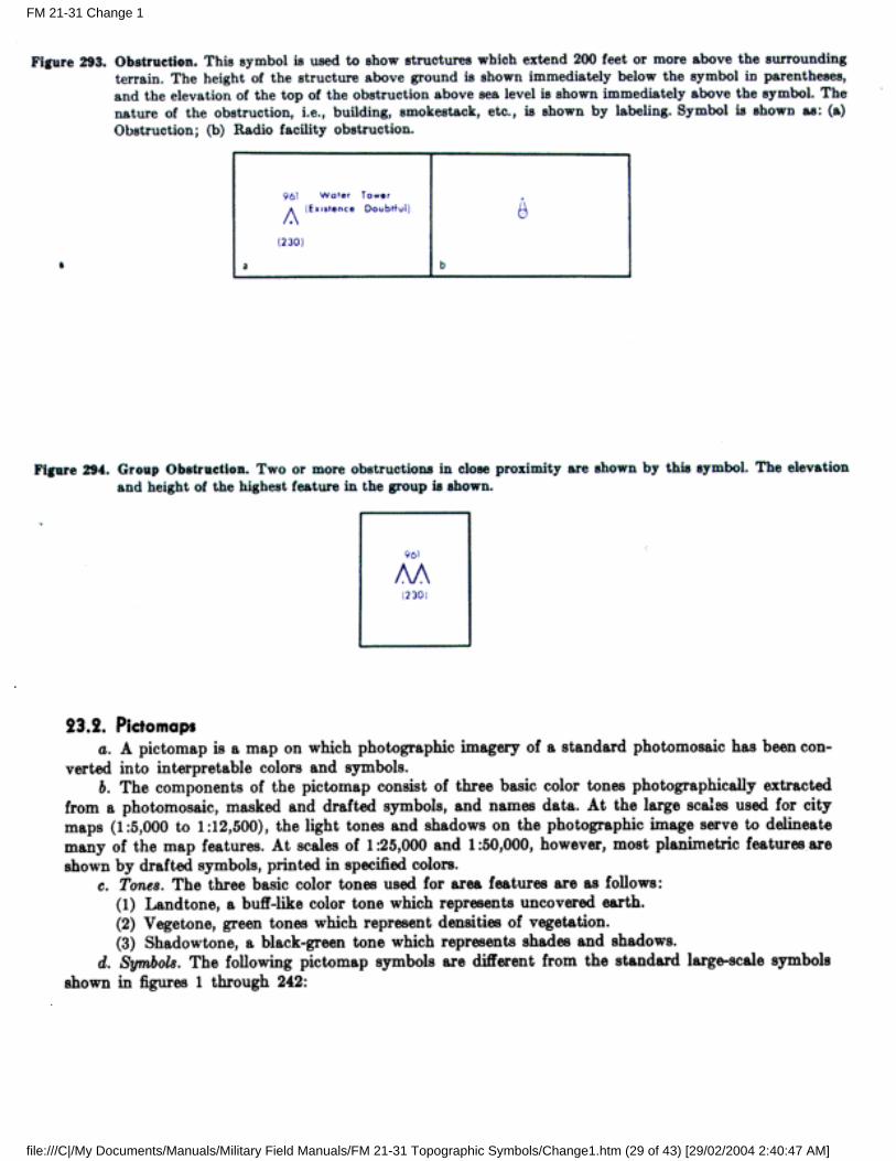
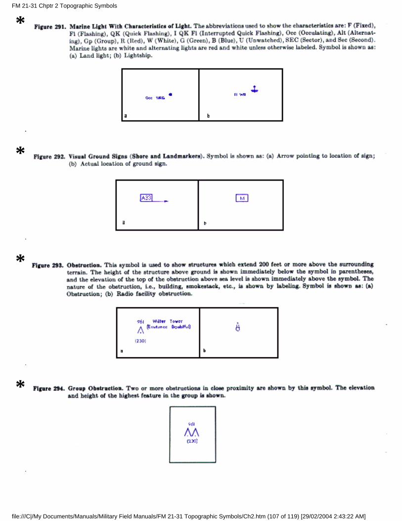
(10) Visual aids and obstructions. The following figures show the approved symbols for visualaids and obstructions to aerial navigation:
*
FM 21-31 Chptr 2 Topographic Symbols
file:///C|/My Documents/Manuals/Military Field Manuals/FM 21-31 Topographic Symbols/Ch2.htm (105 of 119) [29/02/2004 2:43:22 AM]
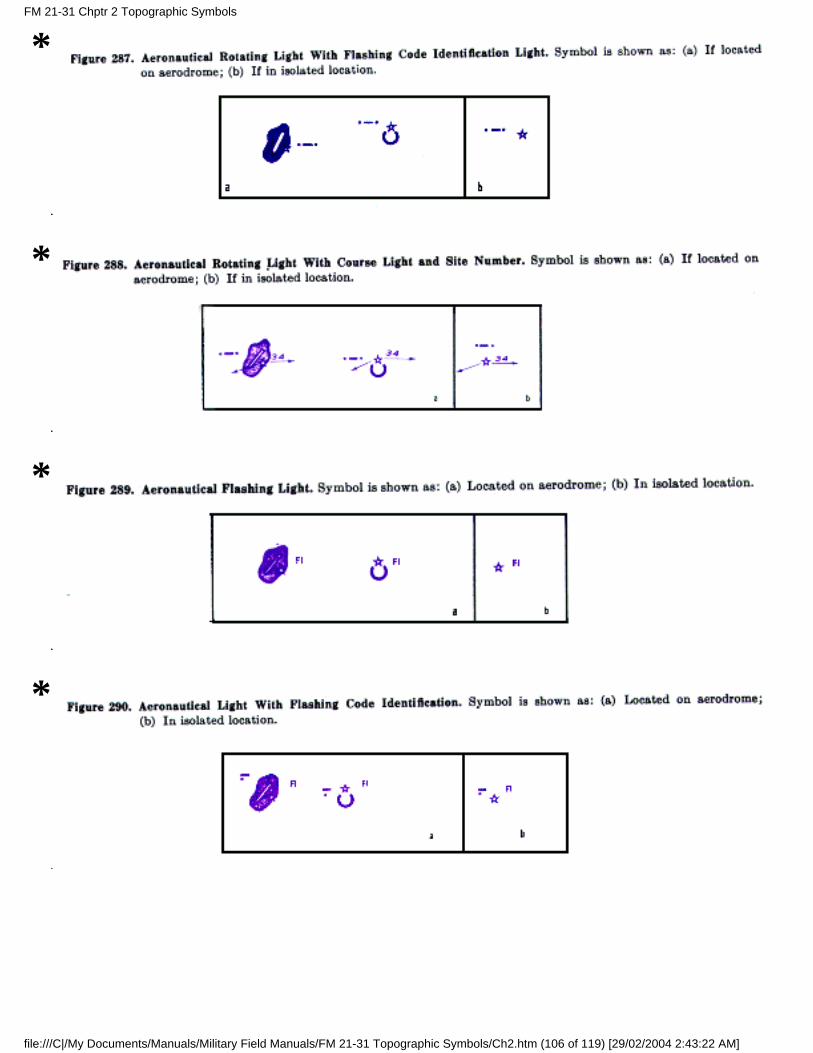
*
*
*
*
FM 21-31 Chptr 2 Topographic Symbols
file:///C|/My Documents/Manuals/Military Field Manuals/FM 21-31 Topographic Symbols/Ch2.htm (106 of 119) [29/02/2004 2:43:22 AM]
*
*
*
*
FM 21-31 Chptr 2 Topographic Symbols
file:///C|/My Documents/Manuals/Military Field Manuals/FM 21-31 Topographic Symbols/Ch2.htm (107 of 119) [29/02/2004 2:43:22 AM]
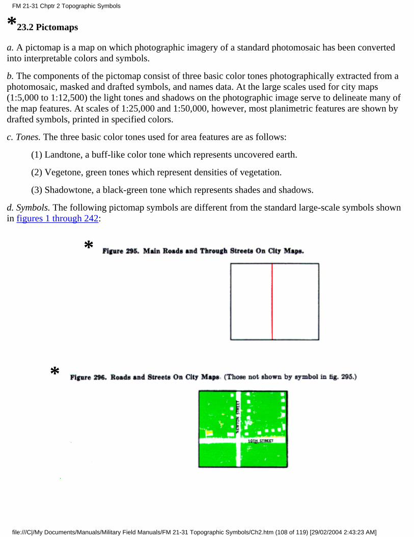
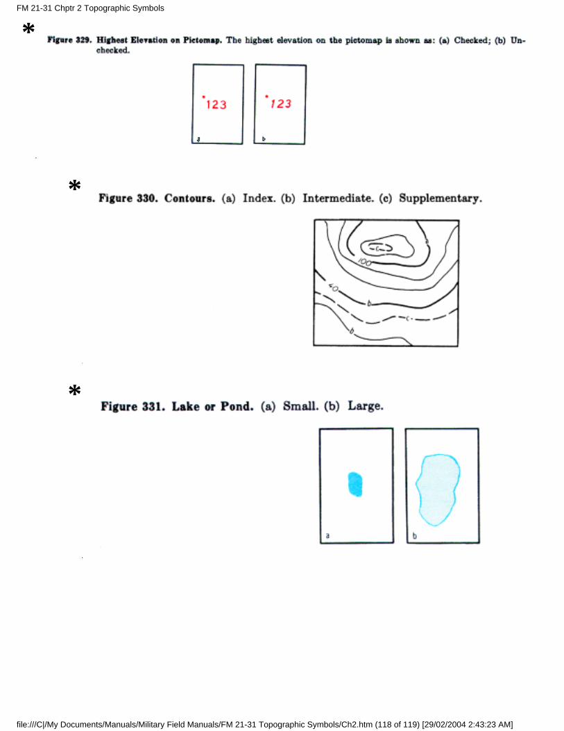
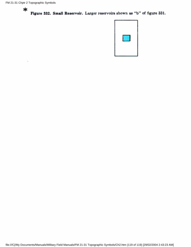
*23.2 Pictomaps
a. A pictomap is a map on which photographic imagery of a standard photomosaic has been convertedinto interpretable colors and symbols.
b. The components of the pictomap consist of three basic color tones photographically extracted from aphotomosaic, masked and drafted symbols, and names data. At the large scales used for city maps(1:5,000 to 1:12,500) the light tones and shadows on the photographic image serve to delineate many ofthe map features. At scales of 1:25,000 and 1:50,000, however, most planimetric features are shown bydrafted symbols, printed in specified colors.
c. Tones. The three basic color tones used for area features are as follows:
(1) Landtone, a buff-like color tone which represents uncovered earth.
(2) Vegetone, green tones which represent densities of vegetation.
(3) Shadowtone, a black-green tone which represents shades and shadows.
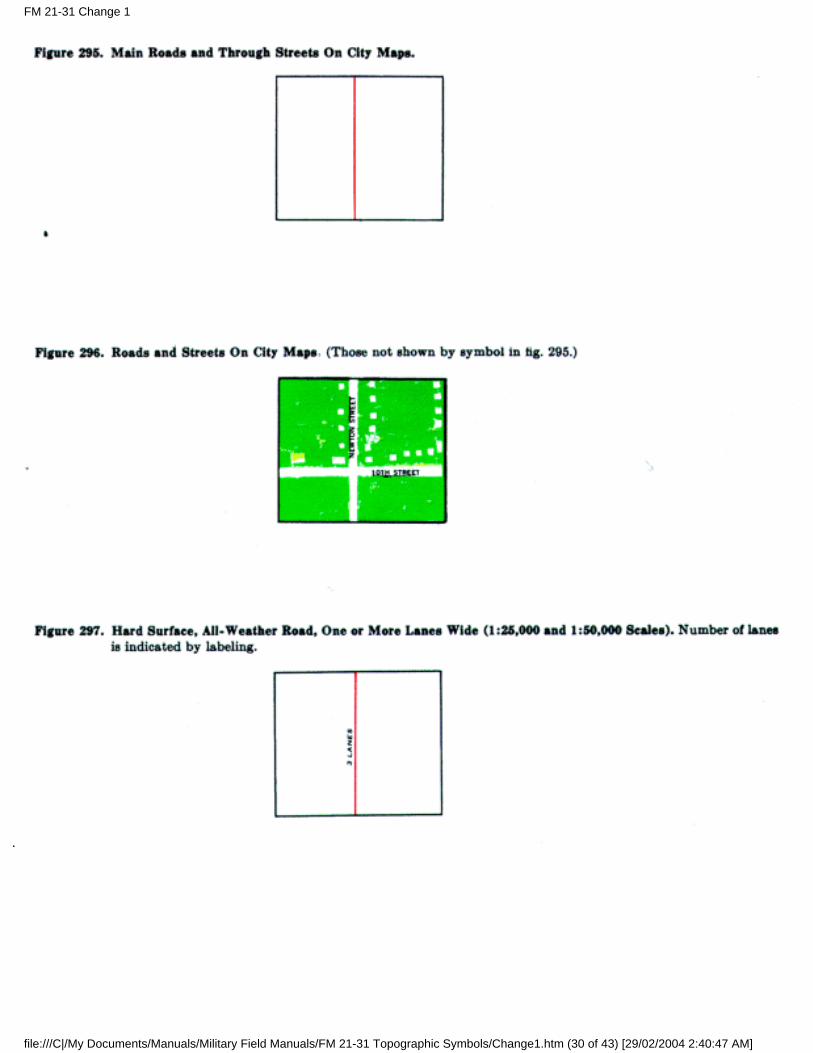
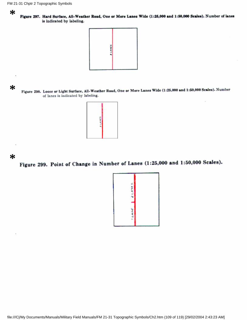
d. Symbols. The following pictomap symbols are different from the standard large-scale symbols shownin figures 1 through 242:
*
*
FM 21-31 Chptr 2 Topographic Symbols
file:///C|/My Documents/Manuals/Military Field Manuals/FM 21-31 Topographic Symbols/Ch2.htm (108 of 119) [29/02/2004 2:43:23 AM]
*
*
*
FM 21-31 Chptr 2 Topographic Symbols
file:///C|/My Documents/Manuals/Military Field Manuals/FM 21-31 Topographic Symbols/Ch2.htm (109 of 119) [29/02/2004 2:43:23 AM]
*
*
*
*
FM 21-31 Chptr 2 Topographic Symbols
file:///C|/My Documents/Manuals/Military Field Manuals/FM 21-31 Topographic Symbols/Ch2.htm (110 of 119) [29/02/2004 2:43:23 AM]
*
*
*
*
FM 21-31 Chptr 2 Topographic Symbols
file:///C|/My Documents/Manuals/Military Field Manuals/FM 21-31 Topographic Symbols/Ch2.htm (111 of 119) [29/02/2004 2:43:23 AM]
*
*
*
*
FM 21-31 Chptr 2 Topographic Symbols
file:///C|/My Documents/Manuals/Military Field Manuals/FM 21-31 Topographic Symbols/Ch2.htm (112 of 119) [29/02/2004 2:43:23 AM]
*
*
*
*
FM 21-31 Chptr 2 Topographic Symbols
file:///C|/My Documents/Manuals/Military Field Manuals/FM 21-31 Topographic Symbols/Ch2.htm (113 of 119) [29/02/2004 2:43:23 AM]
*
*
*
FM 21-31 Chptr 2 Topographic Symbols
file:///C|/My Documents/Manuals/Military Field Manuals/FM 21-31 Topographic Symbols/Ch2.htm (114 of 119) [29/02/2004 2:43:23 AM]
*
*
*
FM 21-31 Chptr 2 Topographic Symbols
file:///C|/My Documents/Manuals/Military Field Manuals/FM 21-31 Topographic Symbols/Ch2.htm (115 of 119) [29/02/2004 2:43:23 AM]
*
*
*
FM 21-31 Chptr 2 Topographic Symbols
file:///C|/My Documents/Manuals/Military Field Manuals/FM 21-31 Topographic Symbols/Ch2.htm (116 of 119) [29/02/2004 2:43:23 AM]
*
*
*
*
FM 21-31 Chptr 2 Topographic Symbols
file:///C|/My Documents/Manuals/Military Field Manuals/FM 21-31 Topographic Symbols/Ch2.htm (117 of 119) [29/02/2004 2:43:23 AM]
*
*
*
FM 21-31 Chptr 2 Topographic Symbols
file:///C|/My Documents/Manuals/Military Field Manuals/FM 21-31 Topographic Symbols/Ch2.htm (118 of 119) [29/02/2004 2:43:23 AM]
*FM 21-31 Chptr 2 Topographic Symbols
file:///C|/My Documents/Manuals/Military Field Manuals/FM 21-31 Topographic Symbols/Ch2.htm (119 of 119) [29/02/2004 2:43:23 AM]
RDLHomepage
Table ofContents
DocumentInformation
DownloadInstructions
CHAPTER 3TOPOGRAPHIC ABBREVIATIONS
24. List of Abbreviations
Appendix II contains the list of topographic abbreviations. with their meanings, authorized for use on thestandard topographic maps discussed in this manual.
25. Application
a. Abbreviations on the face of the map are held to an absolute minimum. They are employed only wherespace prohibits the use of a full term or where use of the full term would require unreasonable repetition.
b. Periods are omitted from abbreviations on the face of the map. In the margin, periods normally areretained. They are, however, omitted from coded abbreviations of governmental agency names. In suchcases, no spacing is shown between the coded letters.
c. In addition to the abbreviations listed herein, commonly accepted abbreviations of time, measures, andcountries are authorized.
FM 21-31 Chptr 3 Topographic Abbreviations
file:///C|/My Documents/Manuals/Military Field Manuals/FM 21-31 Topographic Symbols/Ch3.htm [29/02/2004 2:44:25 AM]
RDLHomepage
Table ofContents
DocumentInformation
DownloadInstructions
CHAPTER 4
MARGINAL INFORMATION
26. Scope
a. This chapter explains the map identifications and other marginal data appearing on topographic mapsprepared for use by the Department of the Army.
b. These marginal items are illustrated in the charts which appear in appendix III. They are--
Chart 1--large-scale and 1:100,000 scale maps.
Chart 2--medium-scale (except 1:100, 000) maps.
Chart 3--1:1,000,000 scale maps.
c. The arrangement of marginal items will vary. For example, on sheets having a narrow east-westneatline dimension, certain items will appear in the right-hand margin rather than in the lower margin.The composition is generally the same for maps of like scales.
d. Detailed information on marginal data will be found in AMS technical manuals and style sheetspublished under the direction of the Chief of Engineers.
27. Map Identifications
a. Purpose. Map identifications are those items appearing in the margins of maps which serve to identifyany individual map completely. On maps prepared for the Department of the Army, these identificationsare the series name and scale, the series number, the edition number, the sheet name, the sheet number,the unit imprint, and the geographic location name.
b. Series Name and Scale. A map series, which normally consists of a common scale of maps whichcollectively cover a specific area, is generally assigned the geographic or political name of the areacovered. The map scale is written as a ratio of map distance to ground distance. Example: GERMANY1:25,000.
c. Series Number. The series number is a comprehensive reference composed of four and sometimes fiveelements, usually four numerals or a letter and three numerals. The number is unique for the series. Itidentifies the area and scale of the series. Example: M841.
d. Edition Number. The edition number is a specific identification based on the publication sequence of aparticular map. Edition numbers run consecutively; thus, it can be assumed that a map labeled with a
FM 21-31 Chptr 4 Marginal Information
file:///C|/My Documents/Manuals/Military Field Manuals/FM 21-31 Topographic Symbols/Ch4.htm (1 of 4) [29/02/2004 2:45:04 AM]
higher edition number contains more recent information than another printing with a lower editionnumber. The edition number also identifies the agency which produced the map. Example: Edition4-AMS.
e. Sheet Name. Generally, a map is named after its outstanding cultural or geographic feature. The nameof a cultural feature is customarily chosen, but if a geographic feature is better known than any culturalfeature appearing on the map, the geographic name is chosen. Example: FORT KNOX.
f. Sheet Number. Sheet numbers for large-scale maps are based on an arbitrary geographic coordinatesystem covering the area to be mapped. The sheet number of a 1:25,000 scale sheet is directly related tothe number of a 1:50, 000 scale sheet covering the same area, which in turn is directly related to the sheetnumber of a 1:100,000 scale sheet covering the same area. Sheet numbers for 1:250,000 and 1:1,000, 000scale maps are based on the International Map of the World (IMW) numbering system. Examples:1:25,000--6123 III NW; 1:50,000--6123 III; 1:100,000--6123 ; 1:250,000--NJ 16-4 ; 1:1,000,000--NJ 16.
g. Unit Imprint. The unit imprint is the signature of the agency responsible for printing the map. This isfollowed by the date identifying the particular printing. Example: Printed by Army Map Service, Corpsof Engineers, 7-60.
h. Geographic Location Name. The geographic location name indicates the country, state, or generalgeographic area within which the map lies. The geographic location name includes the sheet name,which is repeated in the lower margin. Large-scale maps of the United States which cover an areaentirely within one county or parish, carry the county or parish name below the sheet name andgeographic location name. Example: FUJI--SAN, JAPAN.
i. Refer to Note. In the upper right corner of the map margin, the sheet number and series number aregrouped under a note, REFER TO THIS MAP AS. This group provides the primary identification forordering copies of a map.
Example: REFER TO THIS MAP AS:SHEET NJ 16-4SERIES V501
j. Identification Panels. For quick identification of maps when filed or stacked, identification panels inopposite corners of the map sheet, outside the printed limits of other marginal information, are provided.These panels contain the series number, sheet number, and edition number.
Example: SERIES 1301SHEET NK52EDITION 2-AMS
28. Other Marginal Data
In addition to the identifications described above, the margin of a map contains other informationimportant to the user in evaluating and interpreting the map (table I).
FM 21-31 Chptr 4 Marginal Information
file:///C|/My Documents/Manuals/Military Field Manuals/FM 21-31 Topographic Symbols/Ch4.htm (2 of 4) [29/02/2004 2:45:04 AM]
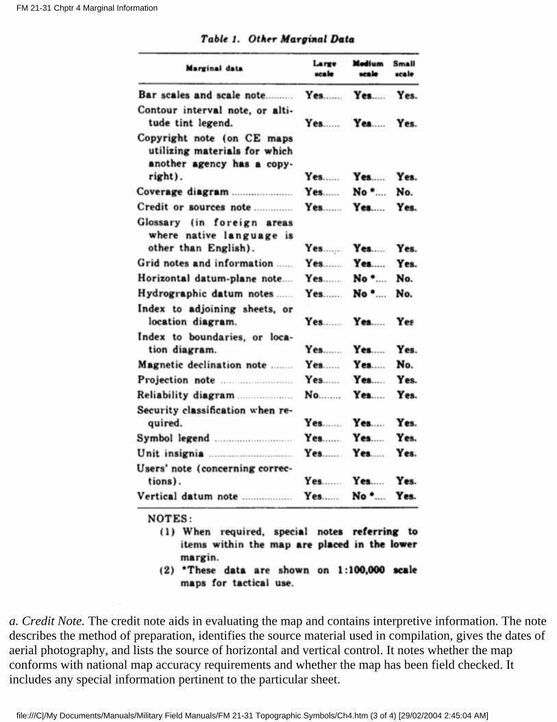
a. Credit Note. The credit note aids in evaluating the map and contains interpretive information. The notedescribes the method of preparation, identifies the source material used in compilation, gives the dates ofaerial photography, and lists the source of horizontal and vertical control. It notes whether the mapconforms with national map accuracy requirements and whether the map has been field checked. Itincludes any special information pertinent to the particular sheet.
FM 21-31 Chptr 4 Marginal Information
file:///C|/My Documents/Manuals/Military Field Manuals/FM 21-31 Topographic Symbols/Ch4.htm (3 of 4) [29/02/2004 2:45:04 AM]
b. Symbol Legend. The symbol legend defines and illustrates the symbols most commonly used such aspopulated places, roads, and rail roads. It also contains symbols for items peculiar to the area beingmapped.
c. Index to Adjoining Sheets. The index to adjoining sheets, or on 1:250,000 scale maps the locationdiagram, identifies the surrounding sheets.
d. Index to Boundaries. The index to boundaries identifies the political areas appearing in the body of themap. The boundaries in the diagram are schematic but serve as aids in locating the boundaries on themap. On the 1:250,000 scale maps this information is shown in the location diagram.
e. Coverage Diagram. The coverage diagram, shown on large-scale maps, portrays in graphic form themethods of compilation, notes the dates of any photography used, and identifies and evaluates any mapsused as bases.
f. Reliability Diagram. The reliability diagram, shown on medium-and small-scale maps, containsgraphic references to the reliability of the sources used and identifies the scale, method of survey, anddate of the basic sources.
g. Datum Notes. The horizontal, vertical, and hydrographic datum notes identify the controls used forthese items on the map. Generally, horizontal and hydrographic datum notes are not shown onmedium-and small-scale maps.
h. Grid Notes and Data. Maps of 1:1,000,000 and larger scale contain grid notes and a grid reference boxwith sample reference, to explain the grid data on the map. Maps carrying 1,000-unit-interval grid linesalso show a declination diagram and a protractor scale in the margin. The declination diagram shows therelationship bet wee n true north, magnetic north, and grid north for the major grid at the center of thesheet. Maps carrying 10,000-unit-interval grid lines show a magnetic declination note. This noteindicates the variation in the east and west map edges. It also shows the mean annual change.
FM 21-31 Chptr 4 Marginal Information
file:///C|/My Documents/Manuals/Military Field Manuals/FM 21-31 Topographic Symbols/Ch4.htm (4 of 4) [29/02/2004 2:45:04 AM]
RDLHomepage
Table ofContents
DocumentInformation
DownloadInstructions
APPENDIX I
REFERENCES
1. Army Regulations (AR)
AR 117-5 Military Mapping and Surveying.
AR 320-5 Dictionary of United States Army Terms.
AR 320-50 Authorized Abbreviations and Brevity Codes.
2. Department of the Army Pamphlets (DA Pam)
DA PAM 108-1 Index of Army Motion Pictures, Film Strips, Slides and Phono-Recordings.
DA PAM 310-1 Military Publications: Index of Administrative Publications.
DA PAM 310-3 Military Publications: Index of Training Publications.
DA PAM 310-4 Index of Technical Manuals, Technical Bulletins, Supply Bulletins, Lubrication Orders,and Modification Work Orders.
DA PAM 310-5 Military Publications: Index of Graphic Training Aids and Devices.
DA PAM 310-7 Military Publications: Index of Tables of Organization and Equipment, Type Tables ofDistribution and Tables of Allowances.
DA PAM 310-25 Military Publications: Index of Supply Manuals, Corps of Engineers.
3. Field Manuals (FM)
FM 5-1 Engineer Troop Organizations and Operations.
FM 5-30 Engineer Intelligence.
FM 21-5 Military Training.
FM 21-6 Techniques of Military Instruction.
FM 21-26 Map Reading.
FM 21-30 Military Symbols.
FM 30-5 Combat Intelligence.
FM 21-31 APPENDIX I
file:///C|/My Documents/Manuals/Military Field Manuals/FM 21-31 Topographic Symbols/App1.htm (1 of 5) [29/02/2004 2:45:54 AM]
FM 30-10 Terrain Intelligence.
FM 101-10, Part I Staff Officer's Field Manual: Organization, Technical and Logistical Data.
4. Technical Manuals (TM)
TM 5-230 General Drafting.
TM 5-240 A Guide to the Compilation and Revision of Maps.
TM 5-244 Multiplex Mapping.
TM 5-245 Map Reproduction.
TM 5-248 Foreign Maps.
TM 5-9990 Kit Instruction Map Reading.
TM 30-246 Tactical Interpretation of Air Photos.
5. Tables of Organization and Equipment
TOE 5-55D Engineer Topographic Battalion, Army.
TOE 5-56D Headquarters and Headquarters Company, Engineer Topographic Battalion, Army.
TOE 5-57D Engineer Map Reproduction and Distribution Company, Army.
TOE 5-59D Engineer Photomapping Company, Army.
TOE 5-167C Engineer Topographic Company, Corps.
TOE 5-344R Engineer Base Map Depot Company.
TOE 5-446D Headquarters and Headquarters Detachment, Engineer Base Topographic Battalion.
TOE 5-347D Engineer Base Reproduction Company.
TOE 5-348D Engineer Base Survey Company.
TOE 5-349D Engineer Base Photomapping Company.
TOE 5-500C Engineer Service Organization:
1A Engineer Topographic Staff Team.1B Engineer Survey Team.1C Engineer Survey Platoon.1D Engineer Photomapping Platoon.1E Engineer Reproduction Platoon.1F Engineer Map Distribution Platoon.1G Engineer Relief Map Making Team.1H Engineer Relief Map Making Platoon.1N Engineer Hydrology Team.1P Engineer Geodetic Survey Team.
FM 21-31 APPENDIX I
file:///C|/My Documents/Manuals/Military Field Manuals/FM 21-31 Topographic Symbols/App1.htm (2 of 5) [29/02/2004 2:45:54 AM]
6. Graphic Training Aids
GTA 5-2 Elementary Map Reading.
GTA 5-12 Coordinate Scales and Protractor.
7. Motion Pictures, Film Strips, Slides, and Phono-Recordings
TF 5-1788 Topographic Symbols.
TF 5-1789 Elevation, Distance, and Grid.
TF 5-1791 Direction, Orientation, and Location With Compass.
TF 5-1790 Direction, Orientation, and Location Without Compass.
TF 5-1792 Photos and Photomaps.
TF 5-1270 British Conventional Signs and Symbols.
TF 5-2406 Azimuth.
TF 5-2409 Contour Lines and Intervals.
TF 5-2410 Direction.
TF 5-2411 Elevation.
TF 5-2412 Intersection.
TF 5-2413 Location.
TF 5-2415 Resection.
TF 5-2416 Scale and Distance.
TF 5-2417 Using the Protractor.
TF 5-2407 Azimuth Conversion.
TF 5-2414 Percent of Slope.
TF 5-2408 Characteristic of Contour Lines.
TF 55-2365 Sextant Adjustment.
TF 5-1546 Multiplex Mapping, Part II.
TF 5-1549 Multiplex Mapping, Part I.
MF 5-8275 Maps for the Army.
8. Army Map Service Technical Manuals
AMS TM 22 Map Identification and Other Marginal Information.
FM 21-31 APPENDIX I
file:///C|/My Documents/Manuals/Military Field Manuals/FM 21-31 Topographic Symbols/App1.htm (3 of 5) [29/02/2004 2:45:54 AM]
AMS TM 23A Symbols for Large-Scale Maps, No Reduction.
AMS TM 33A Symbols for Medium-Scale Maps, No Reduction.
AMS TM 43A Symbols for Small-Scale Maps, No Reduction.
9. Supply Manuals (Sets of Equipment)
SM 5-4 Series
3610-S01 Reproduction Set, Ammonia Process: Reproduction of Line Tracings.
3610-S02 Reproduction Set, Black and White Process: Drawing Tracings.
3610-S07 Reproduction Set, Topographic, Photolithographic: Reproduction Company.
3610-S13 Reproduction Set, Silk Screen Process: Sign Reproduction.
6675-S02 Computing and Drafting Equipment Set: Field Survey Data.
6675-S03 Drafting Equipment Set, Battalion: For Charts, Sketches, and Overlays.
6675-S12 Drafting Equipment Set, Topographic Battalion, Headquarters and Service Company: ForOperational Plans, Maps, Drawings, and Charts.
6675-S13 Drafting Equipment Set, Topographic Battalion, Photomapping Company: For Map Revision,Compilation and Color Separation.
6675-S15 Drafting and Duplication Equipment Set: For Small Sketches, Notes and Orders.
6675-S16 Drafting Instrument Set: Field.
6675-S17 Drafting Instrument Set: Office.
6675-S18 Drafting Instrument Set: Pocket.
6675-S19 Plotting Instrument Set, Stereoplotter Multiplex Control Booth.
6675-S20 Plotting Instrument Set, Stereoplotter, Multiplex Drafting Unit.
6675-S21 Plotting Instrument Set, Stereoplotter, Multiplex Laboratory.
6675-S22 Plotting Instrument Set, Stereoplotter, Multiplex Plotting Booth.
6675-S23 Plotting Instrument Repair Set, Stereoplotter, Projection: For Minor Mechanical Repairs.
6675-S24 Plotting Instrument Repair Set, Stereoplotter, Projection: Supplementary.
6675-S30 Sketching Set, Surveying: Military Field Sketching.
6675-S31 Stereometer Set, Stereocomparagraph, Photogrammetric.
6675-S48 Map Distribution Set: Portable.
6675-S49 Map Distribution Set: Depot.
FM 21-31 APPENDIX I
file:///C|/My Documents/Manuals/Military Field Manuals/FM 21-31 Topographic Symbols/App1.htm (4 of 5) [29/02/2004 2:45:54 AM]
7520-S01 Sign Painting Set.
7610-S07 Book Set: Topographic, General Purpose.
7610-S09 Book Set: Topographic Battalion, Photomapping Company.
7610-S10 Book Set: Topographic Battalion, Reproduction Company.
10. Department of Commerce Publications
a. U.S. Coast and Geodetic Survey Special Publications.
No.
8 Tables and Formulas for the Computation of Geodetic Positions.
28 Application of the Theory of Least Squares to the Adjustment of Triangulations.
68 Elements of Map Projection.
193 Manual of Plane Coordinate Computation.
200 Formulas and Tables for the Computation of Geodetic Positions on the International Ellipsoid.
235 State Coordinate System (Manual for Surveyors).
241 Natural Tables for the Computation of Geodetic Positions.
242 Definitions of Terms Used in Geodetic and Other Surveys.
b. U.S. Coast and Geodetic Survey Serial.
580 Control Surveys and Their Uses.
11. Department of Interior Publications
U.S. Geological Survey Bulletin
Topographic Instructions: Symbols for standard topographic maps published at the scale of 1: 63,360 andlarger, to be scribed at 1: 24,000 and 1: 48,000, dated May 1958.
FM 21-31 APPENDIX I
file:///C|/My Documents/Manuals/Military Field Manuals/FM 21-31 Topographic Symbols/App1.htm (5 of 5) [29/02/2004 2:45:54 AM]
RDLHomepage
Table ofContents
DocumentInformation
DownloadInstructions
APPENDIX II
TOPOGRAPHIC ABBREVIATIONS
A--Army
Aband--abandoned
AF--Air Force
AFB--Air Force Base
Ala-- Alabama
Alin--alinement
Alt--alternate
AMS--Army Map Service
Anc--ancient
Anch--anchorage
Approx--approximate
Apr--April
Arch--archipelago
Ariz--Arizona
Ark--Arkansas
ASE--Army Survey Establishment (Canada)
Aug-- August
Ave-- Avenue
B--bay
Bdry--boundary
Bk--brook
FM 21-31 Appendix II
file:///C|/My Documents/Manuals/Military Field Manuals/FM 21-31 Topographic Symbols/App2.htm (1 of 7) [29/02/2004 2:46:56 AM]
Bldg--building
Blvd--boulevard
BM--benchmark
Br--branch
Brg--bridge
Byp--bypass
C--cape
Calif--California
Cath--cathedral
CE--Corps of Engineers
Cem--cemetery
CG--Coast Guard
CH--courthouse
Ch--church
Chan--channel
Chy--chimney
Co--country
Col--college
Colo--Colorado
Comm--Commission
Conn--Connecticut
Const--construction
CR--crossroads
Cr--creek
Cus Ho--custom house
DC-- District of Columbia
Dec--December
Deg--degrees
FM 21-31 Appendix II
file:///C|/My Documents/Manuals/Military Field Manuals/FM 21-31 Topographic Symbols/App2.htm (2 of 7) [29/02/2004 2:46:56 AM]
Del--Delaware
Dept--department
Div--division
DSvy--Directorate of Military Surveys (Great Britian)
E--east
Elec--electric, electrified
Elev--elevated
Fd--ford
Feb--February
Fl--flood
Fla--Florida
Fld--field
Fm--fathom
For--forest
Ft--fort
Fy--ferry
G--gulf
Ga--Georgia
Gas--gasoline
GN--grid north
Govt--government
Grd--ground
GSGS--Geographic General Staff (Great Britain)
Hbr--harbor
Hosp--hospital
HS--high school
Hy--highway
I--island
FM 21-31 Appendix II
file:///C|/My Documents/Manuals/Military Field Manuals/FM 21-31 Topographic Symbols/App2.htm (3 of 7) [29/02/2004 2:46:56 AM]

Ill--Illinois
In--inlet
Ind--Indiana
Jan--January
Jul--July
Jun--June
Junc--junction
Kans--Kansas
Km--kilometer
Kn--knot
Ky--Kentucky
L--lake
La--Louisiana
Lat--latitude
Ldg--landing
LH--lighthouse
Long--longitude
M--meter (s)
Mag--magnetic
Mar--March
Mass--Massachusetts
Md--Maryland
Mi--mile (s)
Mich--Michigan
Mil--military
Min--minute (s)
Minn--Minnesota
Miss--Mississippi
FM 21-31 Appendix II
file:///C|/My Documents/Manuals/Military Field Manuals/FM 21-31 Topographic Symbols/App2.htm (4 of 7) [29/02/2004 2:46:56 AM]
Mo--Missouri
Mon--monument
Mont--Montana
Mt--mount, mountain
Mts--mountains
N--north
Natl--national
Nav--navigable
NC--North Carolina
N Dak--North Dakota
Nebr--Nebraska
Nev--Nevada
NH--New Hampshire
NJ--New Jersey
NMex--New Mexico
No--number
Nov--November
NY--New York
Obs--obstacle
Obstr--obstruction
Oct--October
Okla--Oklahoma
Oreg--Oregon
P--protractor point (pivot point)
Pa--Pennsylvania
Pen, Pena--peninsula
Pk--peak
Pky--parkway
FM 21-31 Appendix II
file:///C|/My Documents/Manuals/Military Field Manuals/FM 21-31 Topographic Symbols/App2.htm (5 of 7) [29/02/2004 2:46:56 AM]
PO--post Office
Pt--point
PT--Post and telegraph office
Quar--quarantine
Rd--road
Res--reservation
Res--reservoir
RI--Rhode Island
RR--railroad
Rs--radio station
Ry--railway
S--south
SC--South Carolina
Sch--School
S Dak--South Dakota
sec--second (s)
Sept--September
St--saint
St--street
Sta--station
Ste--sainte
Str--stream
Subm--submerged
T--telagraph office
Tel--telephone or telegraph line
Temp--temporary
Tenn--Tennessee
Tex -Texas
FM 21-31 Appendix II
file:///C|/My Documents/Manuals/Military Field Manuals/FM 21-31 Topographic Symbols/App2.htm (6 of 7) [29/02/2004 2:46:56 AM]
Tnpk--turnpike
Tr--tower
Univ--university
US--United States
USC&GS--United States Coast and Geodetic Survey.
USDA--United State Department of Agriculture.
USFS--United States Forest service
USGS--United States Geological Survey.
USNHO United States Navy Hydrographic Office.
USIA United States Lake Survey
Va--Virginia
VABM--vertical angle benchmark
Vil--village
Vt--Vermont
W--West
Wash--Washington
Wdm--Windmill
Wis--Wisconsin
WM--water mill
WT--water tank, water tower
W Va--West Virginia
Wyo--Wyoming
Yd--yard
FM 21-31 Appendix II
file:///C|/My Documents/Manuals/Military Field Manuals/FM 21-31 Topographic Symbols/App2.htm (7 of 7) [29/02/2004 2:46:56 AM]
RDLHomepage
Table ofContents
DocumentInformation
DownloadInstructions
CHART 1
Editor's Note: This graphic is not viewable in HTML format. Check "Download Document" at the topof this file for an alternate format or obtain a printed copy of the document.
CHART 2
Editor's Note: This graphic is not viewable in HTML format. Check "Download Document" at the topof this file for an alternate format or obtain a printed copy of the document.
CHART 3
Editor's Note: This graphic is not viewable in HTML format. Check "Download Document" at the topof this file for an alternate format or obtain a printed copy of the document.
FM 21-31 Appendix III
file:///C|/My Documents/Manuals/Military Field Manuals/FM 21-31 Topographic Symbols/App3.htm [29/02/2004 2:47:54 AM]
Recommended