Fractal Image Compression and Recurrent Iterated
nction Systems John C . Hart Washington State University
ractal geometry provides a basis for mod- F eling the infinite detail found in nature. Fractal methods are quite popular in computer graph- ics for modeling natural phenomena such as moun- tains, clouds, and many kinds of plants. Linear fractal models such as the iterated function system (IFS), recurrent iterated function system (RIFS), and Lindenmeyer systern (L-system) concisely describe complex objects using self-reference. These models hold much promise in computer graphics as geometric representations of detail.
Fractal techniques have recently found application in the field of image compression. The use of fractals for compression has grown into a well-established area of signal processing, but this use sacrifices its "fractal" ori- gins in the search for optimal coding gain.
The siidebar (p. 26) identifies the differences between the fields of fractal image compression and fractal geometry. This article rebuilds the relationship between them to better facilitate the sharing of new results.
Many geometric representations exist for smooth shapes, and each has certain benefits and drawbacks. Computer-aided geometric design has produced many algorithms to convert a given curve or surface descrip- tion into the most appropriate geometric representation for a given task. Likewise, there are several models for linear fractal shapes and several methods for convert- ing between the representations, such as from L-system to RIFS,' from RIFS to L-system,' and from L-system and RIFS to constructive solid g e ~ m e t r y . ~
The representation used by fractal image compression has been called partilioned IFS4 or, synonymously, local IFS.' This article describes a method for converting frac- tal image compression's partitioned/local IFS to fractal geometry's RIFS. This conversion algorithm allows frac- tal image compression to represent any input shape as a linear fractal and permits algorithms developed for lin- ear fractals to be applied to a wider variety of shapes.
Recurrent modeling theory Recurrent modeling is the process of partitioning an
object into components and representing each compo-
nent as a collection of shrunken copies of possibly itself and possibly other components.
Iterated function systems An iterated function system consists of a set of maps
{w,}?=~ from R" into itself. If the maps of an IFS are con- tractive, each IFS includes a single, compact, nonemp- ty setA c R", called its attractoG6 defined as the union of images of itself under the IFS maps:
The Hutchinson operator w is a convenient shorthand notation
N
w(.>= Uw,( . , 1=1 (2)
that allows us to simplify the defin- ition of an IFS attractor as
A = w(A) (3)
Furthermore, the attractorA gets its name from the property that, given any initial nonempty bound- ed set B c R", we have
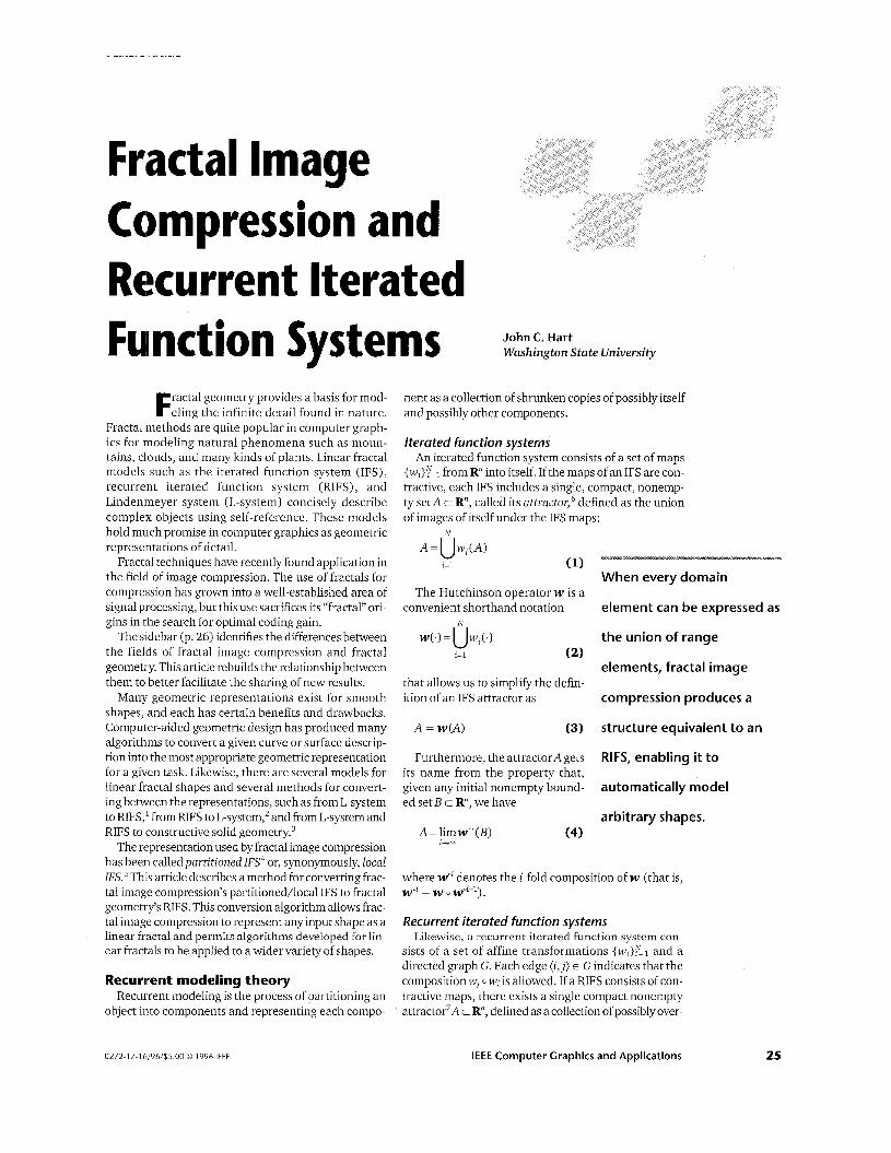
When every domain
element can be expressed as
the union of range
elements, fractal image
compression produces a
structure equivalent to an
RIFS, enabling it to
automatically model
arbitrary shapes. A = limw",(B) (4)
1-00
where wol denotes the i-fold composition of w (that is, w o l = w 0 wOi-1).
Recurrent iterated function systems Likewise, a recurrent iterated function system con-
sists of a set of affine transformations {wi}EJ=1 and a directed graph G. Each edge (i,j) E G indicates that the composition wj 0 wi is allowed. If a RIFS consists of con- tractive maps, there exists a single compact nonempty attractor7A c R", defined as a collection of possiblyover-
0272-1 7-1 61961$5.00 0 1996 IEEE IEEE Computer Graphics and Applications 25
. .
Fractal image compression versus fractal geometry Whilc the term "fractal" appears in both their names, fractal
image compression differs greatly from typical applications of fractal geometry. These differences were fleshed out in a recent NATO Advanced Study institute on Fractal image Compression and Encoding (July 1995, Trondheim, Norway):
1. Fractal image compression performs well on straight edges and flat surfaces, whereas fractal geometry was designed to represent jagged edges and rough surfaces.
2. Fractal image compression blurs texturc in images, whereas frac- tal geometry enhances texture.
3 . Fractal image compression operates on a discrete space, where- as the infinite detail of fractal geometry requires a continuous space.
4. Fractal image compression dices the input into many tiny pieces (and sometimes requires coordinate-dependent functlons) to force self-similarity, whereas fractal geometry capitalizes on a shape's natural self-similarities.
5. Fractal image compression works well even for the worst range- domain matches and works better when similarity is ident,fied with respect to another independent image, whereas fractal geometry is based on cxact or statistically significant self-reference.
26
lapping partitions Aj c R":
N
A = U A ~ j=1
(5)
which are each the union of an image of other partitions (including possibly itself) :
We can keep the components of this partitioning sepa- rate by denoting the attractorA = A1 u A Z u . ' ' UAN as a vector of sets A = (A1, A2, . , , ,AN) t (R")'.
The domain of the RIFS maps extends to set vectors w,: (Rn)N + R", which are defined
(7)
Using these maps, the recurrent Hutchinson operator w:(R")~ + (R")"' is defined on set vectors as
The attractor, consisting of the components defined by Equation 6, is now more concisely defined in set-vector notation as
A = w(A) (9)
to better resemble Equation 3. Moreover, given any set vectorB = (B, B, . . . , B ) c (R")N consisting of bounded nonempty sets B c R", then
July 1996
A = limw'' (9) I + -
To recap, given any initial nonempty bounded set B c R", iterating w on the set vector {B, B, . . . , B } t (Rn)N creates a sequence converging to the set vector A.
If each partition is the union of images of every par- tition including itself, then the graph G is complete and the RIFS is simply an IFS. Hence, every IFS is an RIFS. Thus the remainder of this section focuses on proper- ties of the RIFS representation.
Open set property The degree of overlap of the partitioning is dictated by
the open set property. An RIFS ({wl}$=0, G) satisfies the open set property' if and only if there exists a set-vector U = (Ul, Uz, . . . , UN) of open sets U, c R" such that its image V = w(U) has the property V, c U,, Vi.
Many algorithms use spatial subdivision to process the infinite detail of an RIFS attractor. When an RIFS satisfies the open set property, and the boundaries of the subdivision agree with the boundaries of the open sets, then spatial subdivision algorithms perform opti- mally and quickly eliminate from consideration all but the desired portion of the attractor. When the compo- nents (Al) of an RIFS significantly overlap, such algo- rithms exhaustively search the entire attractor.
Digraph topology A digraph is strongly connected if and only if every pair
of vertices is connected by a directed path of edges. A digraph is weakly connected if and only if every pair of vertices is connected by a path of edges, regardless of edge direction. We follow the convention that strongly connected and weakly connected are mutually exclusive.
Some RIFS algorithms, such as the chaos game in the next section, require a strongly connected digraph, while others do not even require the digraph to be connected.
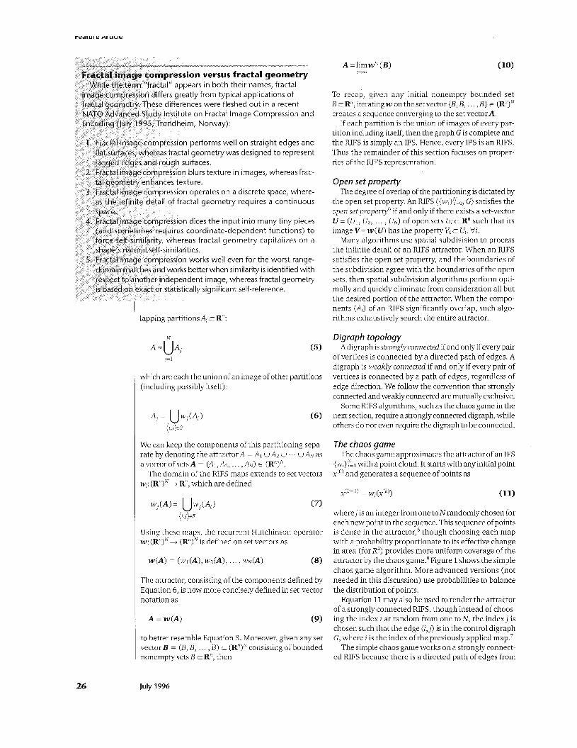
The chaos game The chaos game approximates the attractor of an IFS
{wL}:ll with a point cloud. It starts with any initial point x(O) and generates a sequence of points as
w, ( X ( k ) ) (11) X ( k + l ) =
wherej is an integer from one toNrandomlychosen for each new point in the sequence. This sequence ofpoints is dense in the attractor,' though choosing each map with a probability proportionate to its effective change in area (for R2) provides more uniform coverage of the attractor by the chaos game.8 Figure 1 shows the simple chaos game algorithm. More advanced versions (not needed in this discussion) use probabilities to balance the distribution of points.
Equation 11 may also be used to render the attractor of a strongly connected RIFS, though instead of choos- ing the index i at random from one to N, the index j is chosen such that the edge (i, j) is in the control digraph G, where i is the index of the previously applied map.7
The simple chaos game works on a strongly connect- ed RIFS because there is a directed path of edges from
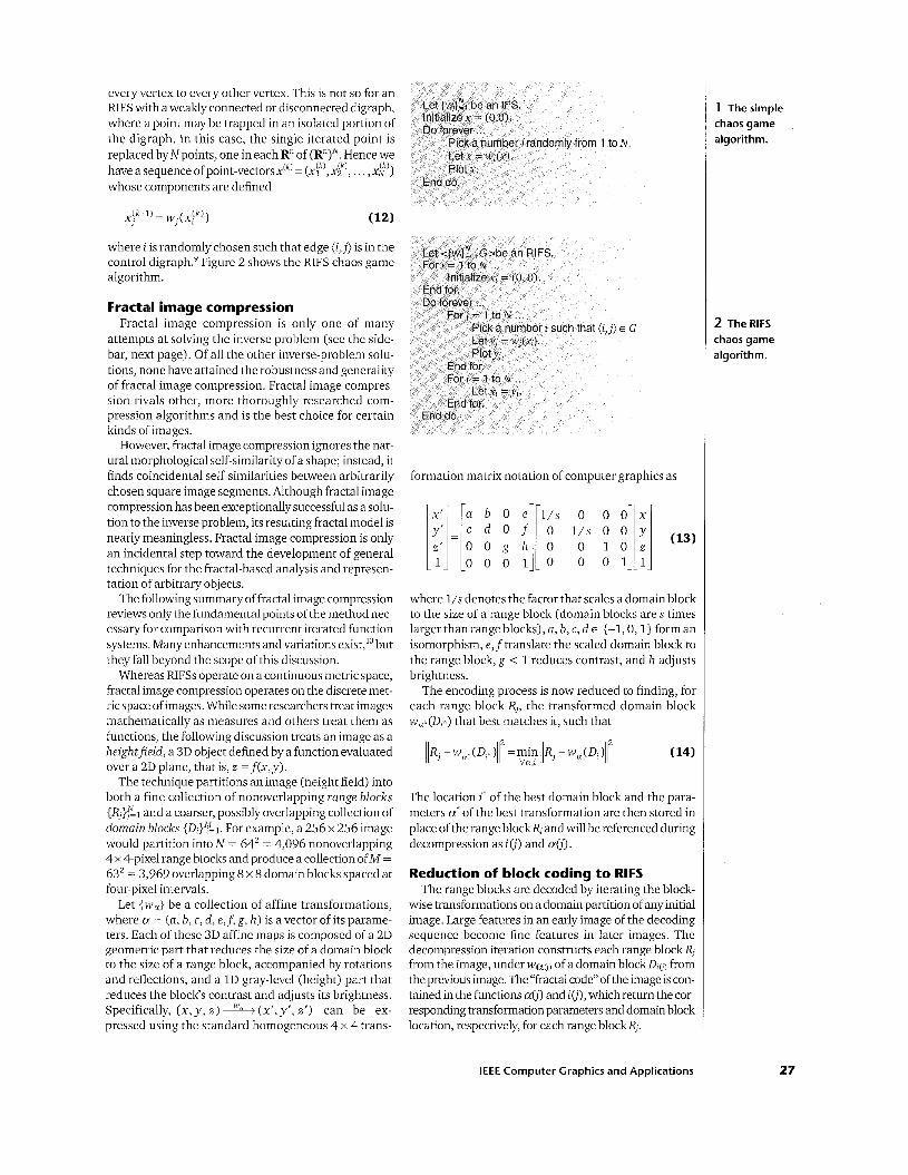
every vertex to every other vertex. This is not so for an RIFS with a weakly connected or disconnected digraph, where a point may be trapped in an isolated portion of the digraph. In this case, the single iterated point is replaced by Npoints, one in each R“ of (R”)N. Hence we have a sequence of point-vectorsx(k) = (xik’,xik’, . . . , x;’) whose components are defined
where i is random1yc:hosen such that edge (i, j) is in the control digraph.’ Figure 2 shows the RIFS chaos game a1gorith.m.
Fractal image compression Fractal image compression is only one of many
attempts at solving the inverse problem (see the side- bar, next page). Of all the other inverse-problem solu- tions, none have attained the robustness and generality of fractal image compression. Fractal image compres- sion rivals other, more thoroughly researched com- pression algorithms and is the best choice for certain kinds of images.
However, fractal innage compression ignores the nat- ural morphological self-similarity of a shape; instead, it finds coincidental self-similarities between arbitrarily chosen square image segments. Although fractal image compression has been exceptionally successful as a solu- tion to the inverse problem, its resulting fractal model is nearly meaningless. Fractal image compression is only an incidental step toward the development of general techniques for the fractal-based analysis and represen- tation oFarbitrary objects.
The following summary of fractal image compression reviews only the fundamental points of the method nec- essary for comparison with recurrent iterated function systems. Many enhancements and variations exist,” but they fall beyond the scope of this discussion.
Whereas RIFSs operate on a continuous metric space, fractal image compression operates on the discrete met- ric space of images. While some researchers treat images mathematically as measures and others treat them as functions, the following discussion treats an image as a heightfield, a 3D object defined by a function evaluated over a 2D plane, that is, z =f(x, y).
The technique partitions an image (height field) into both a fine collection of nonoverlapping range blocks { R j } g ~ and a coarser, possibly overlapping collection of domain blocks {D1}Y= 1. For example, a 256 x 256 image would partition into N = 64’ = 4,096 nonoverlapping 4 x 4-pixel range blocks and produce a collection ofM = 63’ = 3,969 overlapping 8 x 8 domain blocks spaced at four-pixel intervals.
Let {w,} be a collection of affine transformations, where a. = (a, b , c, d , e,f, g, h ) is a vector of its parame- ters. Each of these 3D affine maps is composed of a 2D geometric part that reduces the size of a domain block to the size of a range block, accompanied by rotations and reflections, and a 1 D gray-level (height) part that reduces the block’s contrast and adjusts its brightness. Specifically, (x, y, z j 1- (x’, y’, z’) can be ex- pressed using the standard homogeneous 4 x 4 trans-
formation matrix notation of computer graphics as
where l/s denotes the factor that scales a domain block to the size of a range block (domain blocks ares times larger than range blocks), a, b, c, d E {-1, 0, l} form an isomorphism, e,ftranslate the scaled domain block to the range block, g < 1 reduces contrast, and h adjusts brightness.
The encoding process is now reduced to finding, for each range block R,, the transformed domain block wa-(D1-) that best matches it, such that
The location i of the best domain block and the para- meters a’ of the best transformation are then stored in place of the range blockR, and will be referenced during decompression as io’) and a(j).
Reduction of block coding to RIFS The range blocks are decoded by iterating the block-
wise transformations on a domain partition of any initial image. Large features in an early image of the decoding sequence become fine features in later images. The decompression iteration constructs each range block R, from the image, under wa0) of a domain blockD,(,, from the previous image. The “fractal code” of the image is con- tained in the functions a(j) and i(j), which return the cor- responding transformation parameters and domain block location, respectively, for each range blockR,.
IEEE Computer Graphics and Applications
1 The simple chaos game algorithm.
2 The RIFS chaos game algorithm.
27
of iterated function systems, n an object, find an iterated
s that object within a given roblem techniques in that they are more hape representation. first stepping stone
em. It states that a lazy r self-replicas yields a
Inverse Problem for Fractals and y of Snence, Vol. 83, Apr 1986,
rem relaxed the accuracy of reasonable fractal modeling,
an object out of smaller self-
ng of shapes is based on es. They have yielded
not yet practical. The following is mpts at automatic solutions to
ple, highly constrained method of moments:
rated Function Schemes and the " Proc. Royal Soaety A, Vol. 399,
Problems in Fractal Construction. ysica 0, Vol. 43, 1990, pp 17-36
minimized the difference in tractor and a given shape:
d Function Systems and the ction using Moments," Com- and S.M. Watt, eds., Springer-
arameters that minimized
Fractal Approximation," Con-
Genetic algorithms overcome the problem of I oca1 minima (though a t the expense of numerous "generations" and slow convergence): E.R. Vrscay, "Moment and Collage Methods for the Inverse Problem
of Fractal Construction with Iterated Function Systems," in Frac- tals and the Fundamental and Applied Soences, H-0. Peitgen, 1. Henriques, and L. Penada, eds., North-Holland, New York, 1991, pp 443-461.
A wavelet technique found the parameters of an IFS containing only scales and translations: R. Rinaldo and A Zakhor, "Inverse and Approximation Problem for
Two-Dimensional Fractal Sets," / € E € Trans on lmage Processing, Vol 3, No 6, Nov 1994, pp 802-820
A recent NATO Advanced Study Institute on Fractal lmage Encoding and Analysis explored numerous techniques for using fractals to understand and compress images. Many of these papers are expected to appear in an upcoming special issue of the journal Fractals. Of these papers, only the following three presented morphological solutions to the inverse problem.
metric appeared to behave better for gradient-descent minimization : N Wadstromer, "An Approach to the Inverse IFS Problem using the
The computationally-intensive Kantorovich (Hutchinson)
Kantorovich Metric ' I
The following presentation described a technique for finding the best similarity transformations of an IFS given its fixed points: E. Hocevar and W.C. Kropatsch, "Inventing the Formula of the Trees:
A Solution of the Inverse Problem of the Representation of Self- Similar Images."
The following presentation adapted a model-based computer vision technique (used to identify known models in a scene) to detect self-recurrence of feature points in an image: 1.C Hart, W.O. Cochran, and P.J. Flynn, "Similarity Hashing: A Model-
Based Vision Solution to the Inverse Problem of Recurrent Iterat- ed Function Systems."
The block-coding structure of fractal image compres- sion is a representation of an RIFS. This is most easily seen when the domain blocks do not overlap and their boundaries align with the boundaries of range blocks. However, this result generalizes to include cases of over- lapping and nonaligned domain blocks.
The function a(j) returns the parameters of the trans- formation, and the function i(j) returns the index of the domain block that the transformation maps to range blockR,. For simplicity, we abbreviate web) as wj.
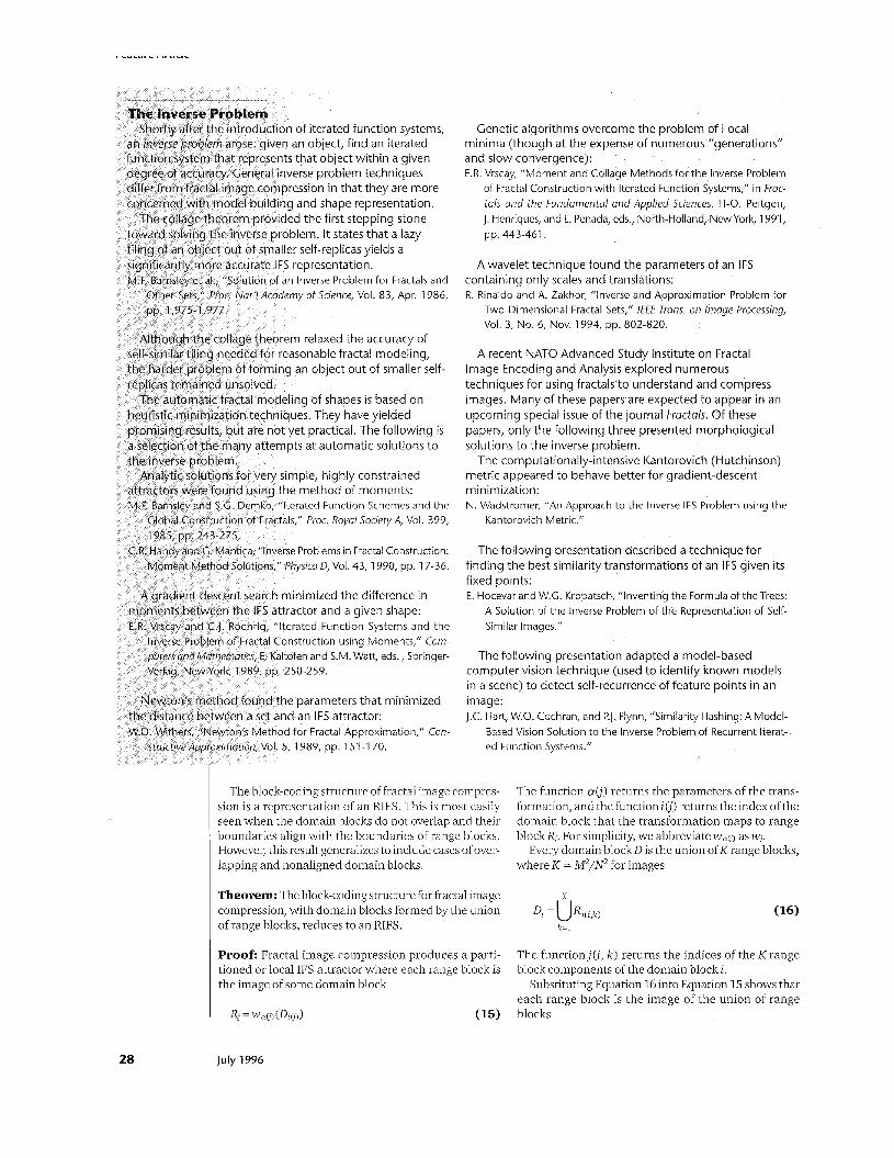
Every domain blockD is the union ofK range blocks, where K = M2/N2 for images
Theorem: The block-coding structure for fractal image compression, with domain blocks formed by the union
K
D, = u R l ( i , , , of range blocks, reduces to an RIFS. k = l
28
Proof: Fractal image compression produces a parti- tioned or local IFS attractor where each range block is the image of some domain block
The function j(i, k ) returns the indices of the Krange block components of the domain block i.
Substituting Equation 16 into Equation 15 shows that each range block is the image of the union of range
= w a ~ ) (DLoI) (15) blocks
July 1996
Since the image of a union is equivalent to the union of images, Equation 17 becomes
as illustrated in Figure 3.
This matches the form of an RIFS attractor (Equation 6) partitioned into range blocksA = (RI, Rz, . . . , RN) with a digraph where each vertex j has an in-count ofK edges (j( i( j) , k ) , j) for 1 2 k 4 K.
Remarks:
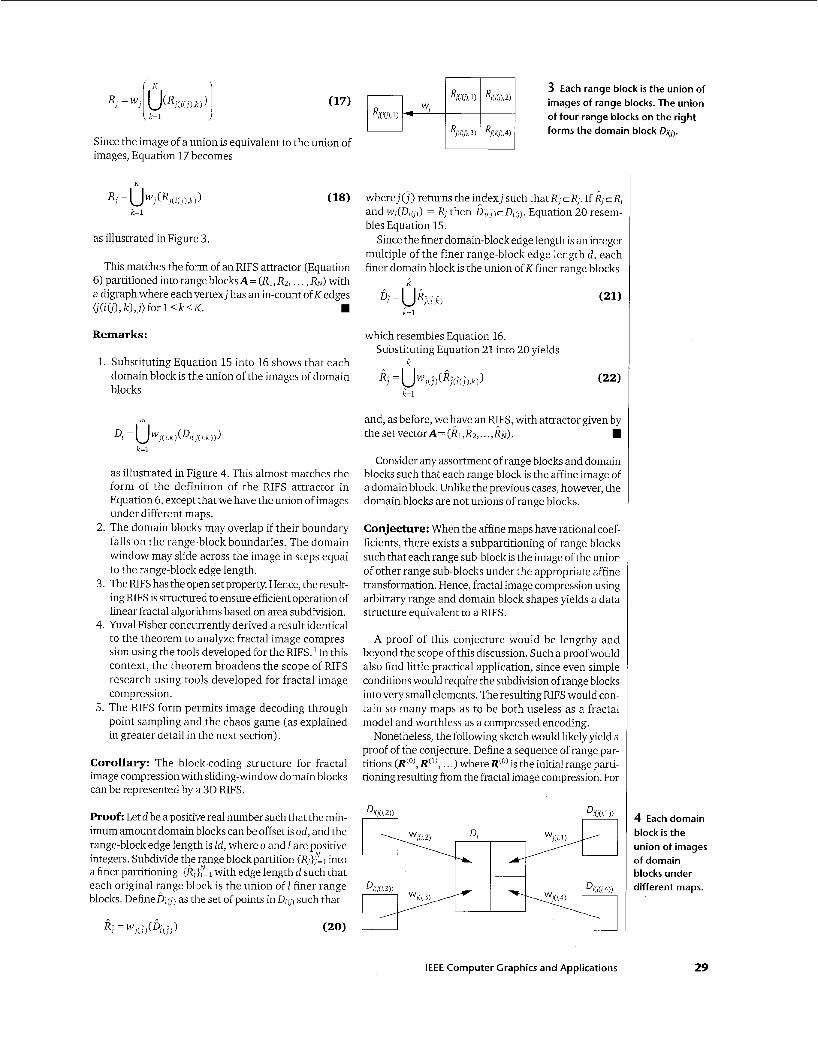
1. Substituting Equation 15 into 16 shows that each domain block is the union of the images of domain blocks
as illustrated in Figure 4. This almost matches the form of the definition of the RIFS attractor in Equation 6, except that we have the union of images under different maps.
2. The domain blocks may overlap if their boundary falls on the range-block boundaries. The domain window may slide across the image in steps equal to the range-block edge length.
3. The RIFS has the open set property. Hence, the result- ing FUFS is structured to ensure efficient operation of linear fractal algorithms based on area subdivision.
4. Yuval Fisher concurrently derived a result identical to the theorem to analyze fractal image compres- sion using the tools developed for the RIFK4 In this context, the theorem broadens the scope of RIFS research using tools developed for fractal image compression.
5. The KIFS form permits image decoding through point sampling and the chaos game (as explained in greater detail in the next section).
Corollary: The block-coding structure for fractal image compression with sliding-window domain blocks can be represented by a 3D RIFS.
Proof: Let d be a positive real number such that the min- imum am'ount domain blocks can be offset is od, and the range-block edge length is Id, where o and 1 are positive integers. Subdivide the range block partition {R$I into a finer partitioning {Rj}y=1 with edge length d such that each original range block is the union of I finer range blocks. Define&) as the set of points in&) such that
Re ! = w . I ( ! ) 1 ( D [ ( I ) 1 ) (20)
3 Each range block is the union of
of four range blocks on the right forms the domain block D,o.
images of range blocks. The union
where j(7) returns the indexj such that R, cR,. If k, cR and w,(D,o)) = R! then D,(,)cD,b). Equation 20 resem- bles Equation 15.
Since the finer domain-block edge length is an integer multiple of the finer range-block edge length d, each finer domain block is the union of K finer range blocks
a 6; = URj(E,i)
k=l
which resembles Equation 16. Substituting Equation 21 into 20 yields
t
and, as before, we have an RLFS, with attractor given by the set vectorA= (R&,. . .,R,+).
Consider any assortment of range blocks and domain blocks such that each range block is the affine image of a domain block. Unlike the previous cases, however, the domain blocks are not unions of range blocks.
Conjecture: When the affine maps have rational coef- ficients, there exists a subpartitioning of range blocks such that each range sub-block is the image of the union of other range sub-blocks under the appropriate affine transformation. Hence, fractal image compression using arbitrary range and domain block shapes yields a data structure equivalent to a RIFS.
A proof of this conjecture would be lengthy and beyond the scope of this discussion. Such a proof would also find little practical application, since even simple conditions would require the subdivision of range blocks into very small elements. The resulting RIFS would con- tain so many maps as to be both useless as a fractal model and worthless as a compressed encoding.
Nonetheless, the following sketch would likely yield a proof of the conjecture. Define a sequence of range par- titions @'), @), . . .) whereR(') is the initial range parti- tioning resulting from the fractal image compression. For
IEEE Computer Graphics and Applications
4 Eachdomain block is the union of images of domain blocks under different maps.
29
rearure Hrucie
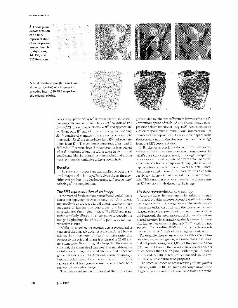
5 Chaosgame decompression of an RlFS representation of a compressed image. From left to right. one, 16,256, and 512 iterations.
6 First few iterations (left) and final attractor (center) of a fingerprint encoded into 1,030 RlFS maps from the original (right).
I
30
?very range partitioning R‘” in the sequence, its accom- panying collection of domain blocks D“’ consists of sets D = w;’(R) for each range blockR E R(’) and appropriate wi. Given both R“) and D‘”, the next range partitioning R(’+’) consists of elements that are each the nonempty intersectionR n D of a range blockfromR(‘ and a domain block from D“) . The sequence converges when and if R(2) = R(‘+’) at some level 4. Convergence is expected after d iterations, when the affine maps have rational coefficients (that is, rational rotation angles) and d is the least common denominator of these coefficients.
Results The conversion algorithm was applied to both grey-
level images and to bitmaps. For a given shape, the algo- rithm can produce an edge image and an “escape time” coloring of the complement.
The RlFS representation of an image One method for decompressing a fractal coded image
consists of applying the domain-range transformations repeatedly to an arbitrary initial image, thus creating a sequence of images that converges to a limit that approximates the original image. The RIFS represen- tation similarly allows the chaos game to decode the image by plotting the orbits of N points, as demon- strated in Figure 5.
While the chaos game reconstructs a recognizable version ofthe image, it does not converge. After 256 iter- ations, the (mean-square) signal-to-noise ratio with respect to the original image is a miserable 21 dB and never improves. Even though the image fidelity remains constant, the image itself changes. The signal-to-noise ratio between images decoded after 256 and 512 chaos game iterations is 21 dB. After only seven iterations, a typical fractal image decompression algorithm” con- verges and yields a signal-to-noise ratio of 1.6 dB with respect to the original image.
The disappointing performance of the RIFS chaos
luly 1996
game is due to inherent differences between the RIFS’s continuous space of reals R3 and fractal image com- pression’s discrete space of integers Z3. A contraction on a discrete space must eliminate some information that cannot later be reproduced. Hence discrete space lacks the necessary information to properly decode the image from the RIFS representation.
In R3, the corresponding value of a pixel maybe con- sidered either an average value ( z component) over the pixel’s area (x, y components), or a single sample ( z ) from a specific point (x,y) in the pixel’s area. For recon- struction of a fractal compressed image, these values typically form a fractal function over the pixel’s area. Sampling a single point in this area returns a chaotic result, and integration of a fractal function is problem- atic. This sampling problem prevents the chaos game on R3 from accurately decoding the image.
The RIFS representation of a bitmap Applying fractal image compression to bilevel images
(bitmaps) provides a more successful application of the chaos game in the decoding process. The pixels in such images are either on or off, and the image can be con- sidered a discrete approximation of a continuous set. In this form, only the geometric part of the transformation is used; the grey-level transformation is always the iden- tity. Range blocks containing only “off” pixels are not encoded. The resulting RIFS form of the fractal encod- ing yields the “on” pixels of the image as its attractor.
For example, the process encoded a 256 x256 xl fin- gerprint, shown in Figure 6, at a range block resolution of 4 x 4 pixels, using only 1,030 of the possible 4,096 RIFS maps. Although the encoded fingerprint appears much noisier than the original, with a signal-to-noise ratio of only 5.9 dB, its features remain and would nev- ertheless serve identification purposes.
The process encoded an artist’s etching of a dragon12 in Figure 7, with 1,048 RIFS maps. Although most of the dragon’s features, such as its bumps and scales, are repro-
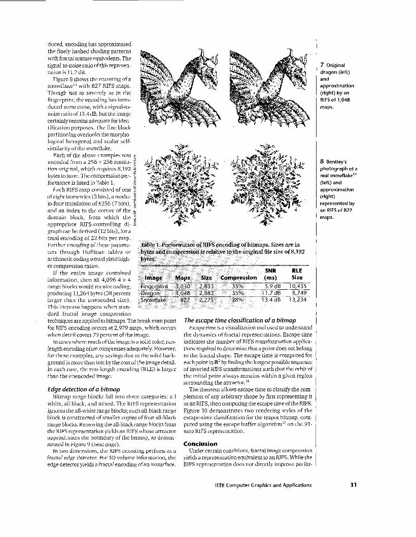
duced, encoding has approximated the finely hashed shading patterns with fractal texture equivalents. The signal-to-noise ratio of this represen- tation is 11.7 dB.
Figure 8 shows the encoding of a snowflake13 with 827 RIFS maps. Though not as severely as in the fingerprint, the encod.ing has intro- duced some noise, wixh a signal-to- noise ratio of 13.4 dB, but the image certainly remains adequate for iden- tification purposes. The fine block partitioning overlooks the morpho- logical hexagonal and scalar self- similarihj of the snowflake.
Each of the above examples was encoded from a 256 x 256 resolu- tion original, which requires 8,192 bytes to store. The Compression per- formance is listed in Table 1.
Each RIFS map consisted of one of eight isometries (3 bits), a modu- lo-four translation of 3-256 (7 bits), and an index to the corner of the domain block, from which the appropriate RIFS-controlling di- graph can be derived (12 bits), for a total encoding of 22 bits per map. Further encoding of these parame- ters through Huffman tables or arithmetic coding woul d yield high- er compression ratios.
If the entire image contained information, then all 4,096 4 x 4 range blocks would require coding, producing 11,264 bytes (38 percent larger than the unencoded size). This increase happens when stan- dard fractal image compression techniques are applied to bitmaps. The break-even point for RIFS encoding occurs at 2,979 maps, which occurs when detail covers 73 percent of the image.
In cases where much (of the image is a solid color, run- length encoding often compresses adequately. However, for these examples, any savings due to the solid back- ground is more than lost by the cost of the image detail. In each case, the run-length encoding (RLE) is larger than the unencoded image.
Edge detection of a bitmap Bitmap range blocks fall into three categories: all
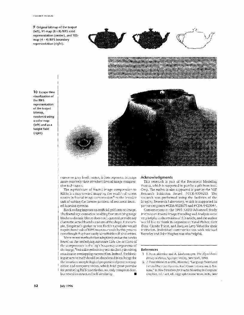
white, all black, and mixed. The RIFS representation ignores the all-white range blocks; each all-black range block is constructed of smaller copies of four all-black range blocks. Removing the all-black range blocks from the RIFS representation yields an RIFS whose attractor approximates the boundary of the bitmap, as demon- strated in Figure 9 (next page).
In two dnmensions, the RIFS encoding perfoms as a fractal edge detector. For 3D volume information, the edge detector yields a fractal encoding of an isosurface.
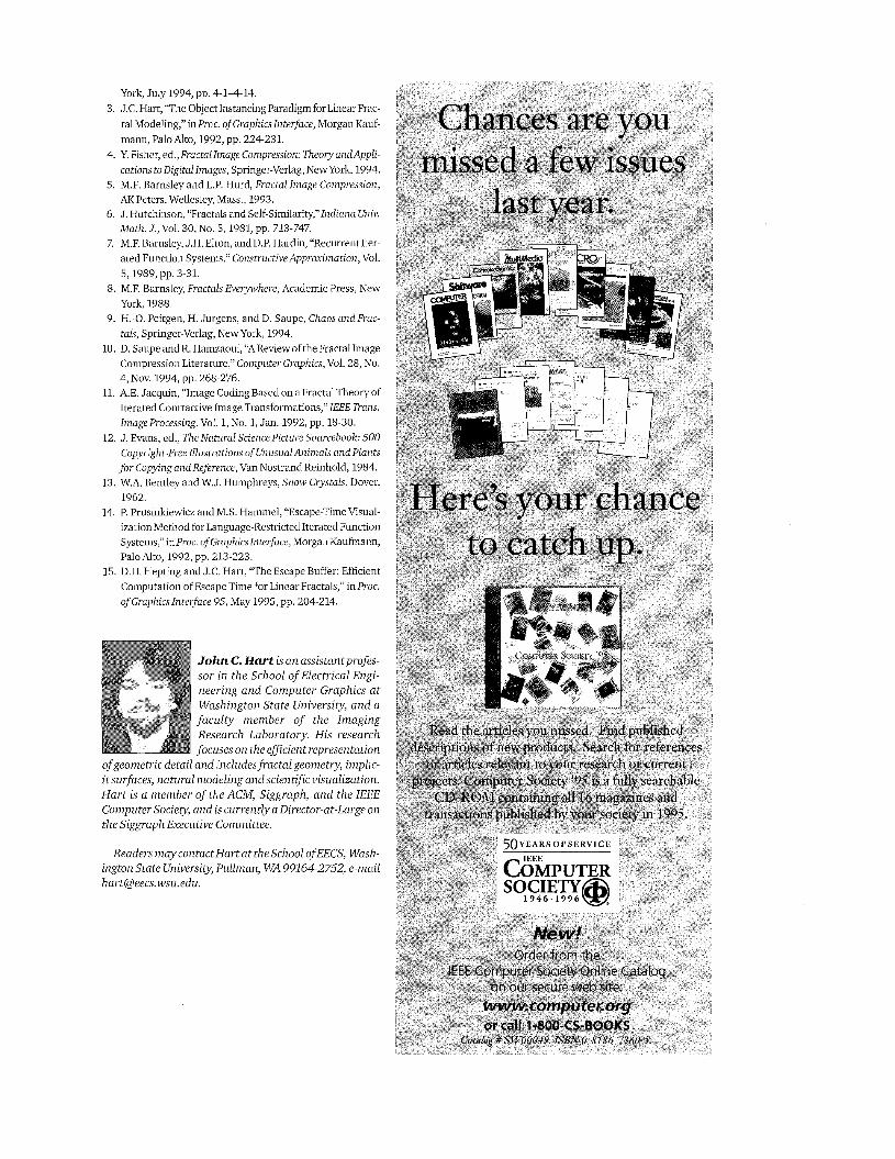
The escape time classification of a bitmap Escape time is a visualization tool used to understand
the dynamics of fractal representations. Escape time indicates the number of RIFS transformation applica- tions required to determine that a point does not belong to the fractal shape. The escape time is computed for each point in R2 by finding the longest possible sequence of inverted RIFS transformations such that the orbit of the initial point always remains within a given region surrounding the attractor.14
The theorem allows escape time to classify the com- plement of any arbitrary shape by first representing it as an RIFS, then computing the escape time of the RIFS. Figure 10 demonstrates two rendering styles of the escape-time classification for the teapot bitmap, com- puted using the escape buffer algorithm15 on the 91- map RIFS representation.
Conclusion Under certain conditions, fractal image compression
yields a representation equivalent to an RIFS. While the RIFS representation does not directly improve perfor-
IEEE Computer Graphics and Applications
7 Original dragon (left) and approximation (right) by an RIFS of 1,048 maps.
8 Bentley’s photograph of a real ~nowflake’~ (left) and approximation (right) represented by an RIFS of 827 maps.
31
reawl c MI LICIC
9 Original bitmap of the teapot (left), 91-map (8 x 8) RlFS solid
- . -2 +--
’i rT Id‘ ,, representation (center), and 103-
map (4 x 4) RlFS boundary representation (right). i‘“ ----
l o Escape time visualization of the RlFS representation of the teapot bitmap, rendered using a color map (left) and as a height field (right).
32
mance on gray-level images, it does represent bitmaps more concisely than standard fractal image compres- sion techniques.
The equivalence of fractal image compression to RIFSs is a step toward mapping the wealth of recent results in fractal image compression” to the broader task of solving the inverse problem of recurrent iterat- ed function systems.
Block coding imposes an artificial grid onto an image. The fractal representation resulting from matching range blocks to domain blocks does not in general provide any clue to the actual fractal structure of the shape. For exam- ple, Sierpinski’s gasket or von Koch’s snowflake would require hundreds of RIFS maps to encode by this process even though they have easily identifiable self-similarities.
More recent methods that adaptively resize the blocks based on the underlying structure hide the artifacts of the compression in the high frequency components of the image,4 but still overlook any self-similarity involving rotations or overlapping construction. Instead, the block- ing structure itself should be abandoned in exchange for the invariant morphological properties of pattern recog- nition and computer vision, which hold great promise for producing RIFS models that not only compress data,
H but reveal its structural self-similarity.
July 1996
Acknowledgments This research is part of the Recurrent Modeling
Project, which is supported in part by a gift from Intel Corp. The author is also supported in part by the NSF Research Initiation Award #CCR-9309210. The research was performed using the facilities of the Imaging Research Laboratory, which is supported in part under grants #CDA-9121675 and #CDA-9422044.
Conversations at the 1995 NATO Advanced Study Institute on Fractal Image Encoding and Analysis were very helpful in the revision of this article, and the author would like to thank its organizers: Yuval Fisher, Geir Bien, Claude Tricot, and Jacques Levy-Vehel for their invitation. Individual communication with Michael Barnsley and John Hughes was also helpful.
References 1. P. Prusinkiewicz and A. Lindenmayer, The Algorithmic
Beauty ofPlants, Springer-Verlag, New York, 1990. 2. P. Prusinkiewicz and M. Hammel, “Language Restricted
Iterated Function Systems, Koch Constructions and L-Sys- tems,” in New Directionsfor Fractal Modeling in Computer Graphics, J.C. Hart, ed., Siggraph Course Notes, ACM, New
York, July 1994, pp. 4-14-14, 3. J.C. H[art, “The Object Instancing Paradigm for Linear Frac-
tal Modeling,” inPrclc. of Graphicslnterface, Morgan Kauf- mann, Palo Alto, 1992, pp. 224-231.
4. Y. Fisher, ed., Fractal Image Compression: Theory andAppli- cations to Digital Images, Springer-Verlag, New York, 1994.
5. M.F. Rarnsley and L.P. Hurd, Fractal Image Compression, AK Peters, Wellesley, Mass., 1993.
6. J. Hutchinson, “Fractals and Self-Similarity,”Indiana U,tiiv. Math. J., Vol. 30, No. 5,1981, pp. 713-747.
7. M.F. Earnsley, J.H. Elton, and D.P. Hardin, “Recurrent k r - ated Function Systems,” Constructive Approximation, Vol. 5,1989, pp. 3-31.
8. M.F. Earnsley, Fractals Everywhere, Academic Press, New York, 1988.
9. H.-0. Peitgen, H. Jurgens, and D. Saupe, Chaos and Frac- tals, Springer-Verlag, New York, 1994.
10. D. Saupe and R. Hamzaoui, “AReview of the Fractal Image Compression Literature,” Computer Graphics, Vol. 28, No.
11. A.E. Jacquin, “Image Coding Based on a Fractal Theory of Iterated Contractive Image Transformations,” IEEE Trans. ImageProcessing, Vol. 1, No. 1, Jan. 1992, pp. 18-30.
12. J. Evans, ed., Tne NaLural Science Picture Sourcebook: 500 Copyright-Free Illustrations of Unusual Animals and Plants for Copying and Reference, Van Nostrand Reinhold, 1984.
13. W.A. Eentley and W.J. Humphreys, Snow Crystals, Dover, 1962.
14. P. Prusinkiewicz and M.S. Hammel, “Escape-Time Visual- ization Method for Language-Restricted Iterated Function Systems,” inProc. of Graphics Interface, Morgan Kaufmann, Palo Alto, 1992, pp. 213-223.
15. D.H. Hepting and J.C. Hart, “The Escape Buffer: Efficient Compiitation of Escape Time for Linear Fractals,” in Pnx. of Graphics Interface 95, May 1995, pp. 204-214.
4, NOV. 1994, pp. 268-276.
John C. H a r t is an assistantprofis- sor i n the School of Electrical Engi- neering and Computer Graphics a t Washington State University, and a facu l t y member of the Imaging Research Laboratory. His research focbses o n the efficient representation
of geometric detail and includesfractal geometry, implic- itsurfaces, natural modeling andscient i fc visualization. Har t is a member of the ACM, Siggraph, and the IEEE Computer Society, and is currently a Director-at-Large o n the Siggraph Executive Committee.
Readers m a y contactHalart a t the School ofEECS, Wash- ington State University, Pullman, WA 99164-2752, e-mail [email protected].
Recommended