7/28/2019 FullManual Manual Bridgeport
http://slidepdf.com/reader/full/fullmanual-manual-bridgeport 1/134
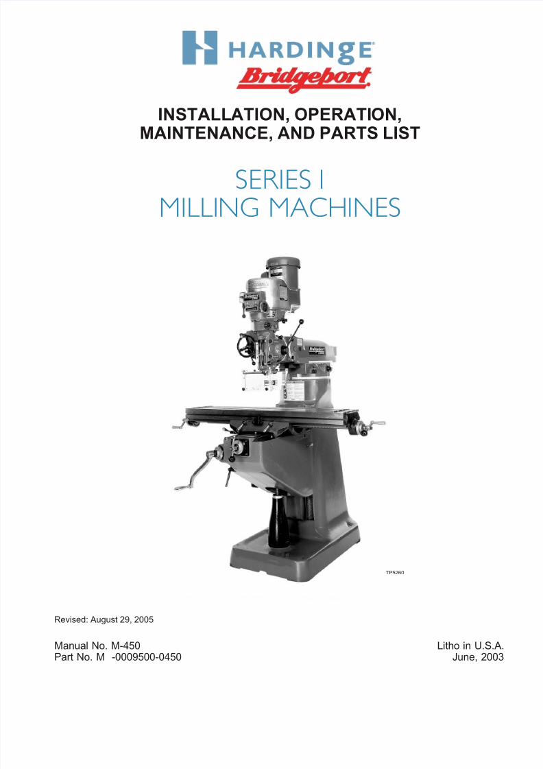
INSTALLATION, OPERATION,
MAINTENANCE, AND PARTS LIST
SERIES I
MILLING MACHINES
Revised: August 29, 2005
Manual No. M-450 Litho in U.S.A
Part No. M -0009500-0450 June, 2003
TP5260

7/28/2019 FullManual Manual Bridgeport
http://slidepdf.com/reader/full/fullmanual-manual-bridgeport 2/134
Information in this manual is subject to change without notice.
This manual covers installation, operation, maintenance, and parts list forSeries I milling machines.
In no event will Hardinge Inc. be responsible for indirect or consequential
damage resulting from the use or application of the information in this man-ual.
Reproduction of this manual, in whole or in part, without written permis-sion of Hardinge Inc. is prohibited.
ORDERING REPLACEMENT PARTS
Please provide the following information when ordering replacement parts:
1. The complete machine serial number. The machine serial number tag is located on thepower case door.
2. List the following:
A. Manual Number (M-450).
B. Page Number.
C. Item Number.
D. Part Description.
E. Part Number.
F. Quantity of each part required.3. Specify how and where to ship.
- NOTICE -
Bridgeport is a registered trademark of Bridgeport Machines, Limited
© 2003, Hardinge Inc. M-450
7/28/2019 FullManual Manual Bridgeport
http://slidepdf.com/reader/full/fullmanual-manual-bridgeport 3/134
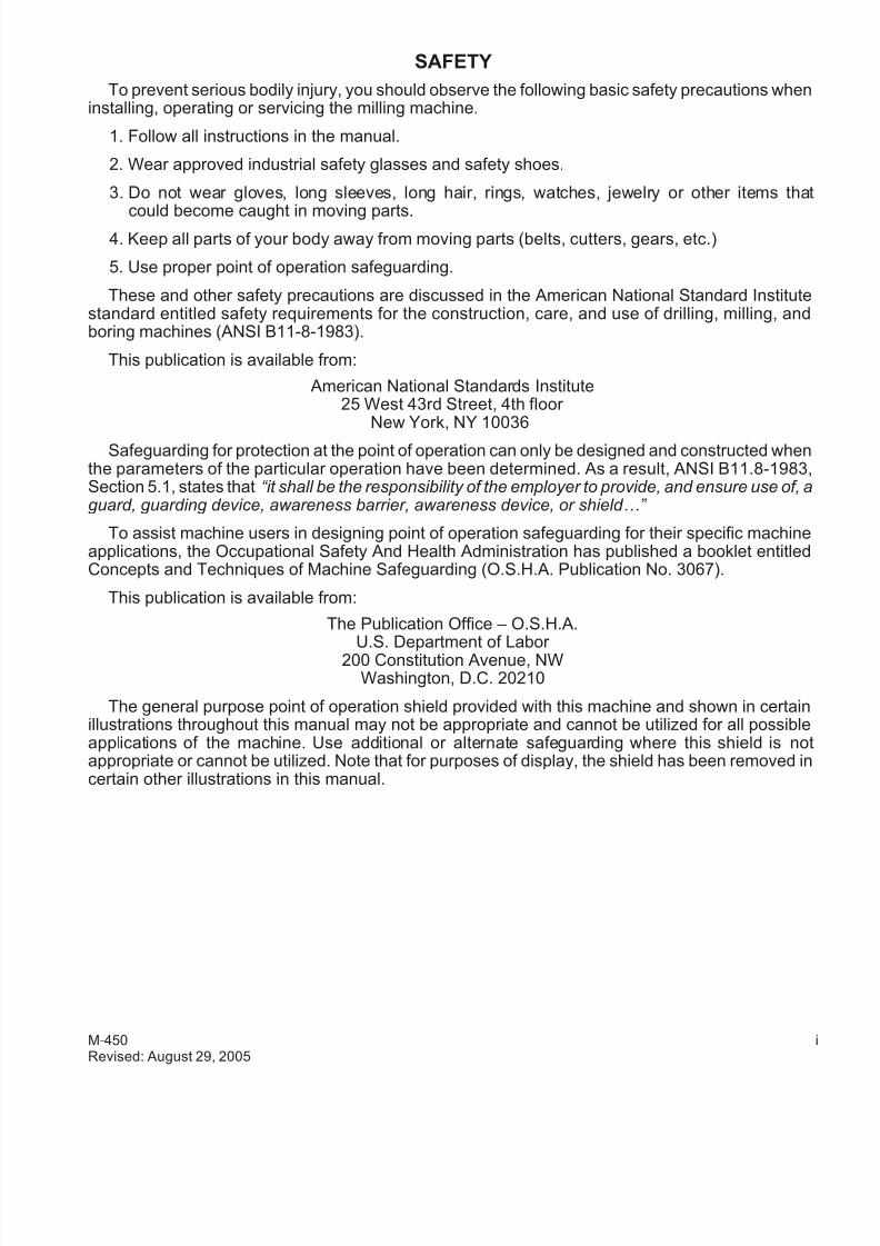
SAFETY
To prevent serious bodily injury, you should observe the following basic safety precautions wheninstalling, operating or servicing the milling machine.
1. Follow all instructions in the manual.
2. Wear approved industrial safety glasses and safety shoes.
3. Do not wear gloves, long sleeves, long hair, rings, watches, jewelry or other items tha
could become caught in moving parts.4. Keep all parts of your body away from moving parts (belts, cutters, gears, etc.)
5. Use proper point of operation safeguarding.
These and other safety precautions are discussed in the American National Standard Institutestandard entitled safety requirements for the construction, care, and use of drilling, milling, andboring machines (ANSI B11-8-1983).
This publication is available from:
American National Standards Institute25 West 43rd Street, 4th floor
New York, NY 10036Safeguarding for protection at the point of operation can only be designed and constructed when
the parameters of the particular operation have been determined. As a result, ANSI B11.8-1983Section 5.1, states that “it shall be the responsibility of the employer to provide, and ensure use of, aguard, guarding device, awareness barrier, awareness device, or shield…”
To assist machine users in designing point of operation safeguarding for their specific machineapplications, the Occupational Safety And Health Administration has published a booklet entitledConcepts and Techniques of Machine Safeguarding (O.S.H.A. Publication No. 3067).
This publication is available from:
The Publication Office – O.S.H.A.
U.S. Department of Labor 200 Constitution Avenue, NW
Washington, D.C. 20210
The general purpose point of operation shield provided with this machine and shown in certainillustrations throughout this manual may not be appropriate and cannot be utilized for all possibleapplications of the machine. Use additional or alternate safeguarding where this shield is noappropriate or cannot be utilized. Note that for purposes of display, the shield has been removed incertain other illustrations in this manual.
M-450 Revised: August 29, 2005

7/28/2019 FullManual Manual Bridgeport
http://slidepdf.com/reader/full/fullmanual-manual-bridgeport 4/134
WARNINGS, CAUTIONS, AND NOTES
- WARNING -
Warning notices are used in this publication to emphasize that hazardousmechanical conditions, voltages, currents, or temperatures exist in thisequipment which could cause serious personal injury and/or damage to theequipment.
- CAUTION -Caution notices are used where equipment might be damaged if care is nottaken.
In situations where inattention could cause either personal injury or damage to the equipment, awarning notice is used.
- NOTE -
Notes merely call attention to information that is especially significant in under-standing and operating the equipment.
This document is intended for the use of those who install, operate and maintain the milling
machine. Although reasonable care has been exercised in the preparation of this manual to make itcomplete and accurate, this manual does not purport to cover all conceivable problems or applications pertaining to this machine.
ii M-450Revised: August 29, 2005

7/28/2019 FullManual Manual Bridgeport
http://slidepdf.com/reader/full/fullmanual-manual-bridgeport 5/134
SAFETY RECOMMENDATIONS
DO NOT OPERATE EQUIPMENT until you have read and understood the appropriate opera-tor and safety maintenance manuals.
DO NOT OPERATE EQUIPMENT until you have read and understood all machine and con-trol key signs.
DO NOT OPERATE EQUIPMENT for the first time without a qualified instructor. Consult your
supervisor when in doubt as to the correct way to perform an operation.
DO NOT OPERATE EQUIPMENT unless proper maintenance has been regularly performedand the equipment is known to be in good working order.
DO NOT ALLOW the operation or repair of equipment by untrained personnel.
WARNING or INSTRUCTION TAGS are mounted on the equipment for your safety and infor-mation. Do not remove them.
DO NOT OPERATE EQUIPMENT if any unusual or excessive heat, noise, smoke, or vibra-tion occurs. Report any excessive or unusual vibration, sounds, smoke, or heat as well as anydamaged parts.
WEAR SAFETY GLASSES with side shields and SAFETY SHOES with steel toes and oil-re-sistant soles at all times. When necessary, wear respirator, helmet, and ear muffs or plugs.
DO NOT OPERATE ANY MACHINE while wearing rings, watches, jewelry, loose clothingneckties, or long hair not contained by a net or shop cap.
DO NOT WEAR GLOVES while operating equipment. Gloves are easily caught in movingparts.
REMOVE ANY LOOSE PARTS OR TOOLS left on machine or in the work area before oper-ating the machine. Always check the machine and work area for loose tools and parts, espe-cially after work has been completed by maintenance personnel.
REMOVE CHUCK WRENCHES before starting the machine.
NEVER OPERATE A MACHINE after taking strong medication, using non-prescription drugsor consuming alcoholic beverages.
SAFEGUARD THE CUTTING ZONE (“point of operation”). Use standard, general purposesafeguards when possible. Use special safeguards when required.
PROTECT YOUR HANDS. Stop the spindle completely before changing tools.
PROTECT YOUR HANDS. Stop the spindle completely before loading or unloading aworkpiece.
DO NOT REMOVE CHIPS with hands. Use a hook or similar device and make certain that allmachine movements have ceased.
DO NOT ADJUST tooling, workpieces or coolant hoses while the machine is running.
PROTECT YOUR HANDS. Stop the spindle completely before taking measurements.
PROTECT YOUR HANDS. Stop the spindle completely before opening safeguards or covers.
NEVER REACH around a safeguard.
M-450 iiRevised: August 29, 2005
7/28/2019 FullManual Manual Bridgeport
http://slidepdf.com/reader/full/fullmanual-manual-bridgeport 6/134
PROTECT YOUR HANDS. Stop the machine before changing or adjusting belts, pulleys or gears.
PROTECT YOUR HANDS. Keep hands and arms clear of spindle start switch when changingtools.
PROTECT YOUR EYES AND THE MACHINE. Never use a compressed air hose to removechips.
KEEP WORK AREA WELL LIGHTED. ask for additional light if needed.DON’T SLIP. Keep your work area clean and dry. Remove chips, oil and obstacles.
NEVER LEAN ON your machine. Stand away when the machine is running.
MAKE CERTAIN that you are clear of any “pinch points” created by moving slides beforestarting the machine.
PREVENT OBJECTS from flying loose. Securely clamp and locate workpiece. Use stopblocks where necessary. Keep clamps clear of cutter path.
PREVENT CUTTER BREAKAGE. Use correct table feed and spindle speed for the job. Re-duce feed and speed if you notice unusual noise or vibration.
PREVENT CUTTER BREAKAGE. Rotate spindle in clockwise direction for right-hand tools,counterclockwise for left-hand tools. Use the correct tool for the job.
PREVENT WORKPIECE and cutter damage. Never start the machine when the cutter is incontact with the workpiece.
DO NOT USE worn or defective tools. Use the proper size and type of tool for the task athand.
KEEP ROTATING CRANKS AND HANDWHEELS well lubricated and maintained. Do not re-move safety springs.
CERTAIN MATERIALS, such as magnesium, are highly flammable in dust and chip form. Seeyour supervisor before working with these materials.
PREVENT FIRE. Keep flammable liquids and materials away from work area and hot chips.
PREVENT MACHINE from moving unexpectedly. Disengage power feed when not being used(manual machines only).
PREVENT MACHINE from moving unexpectedly. Always start machine in manual mode.
UNLESS OTHERWISE NOTED, all operating and maintenance procedures are to be per-formed by one person. To avoid injury to yourself and others, be sure that all personnel areclear of the machine when opening or closing the coolant guard door and any access covers.
iv M-450Revised: August 29, 2005

7/28/2019 FullManual Manual Bridgeport
http://slidepdf.com/reader/full/fullmanual-manual-bridgeport 7/134
INSTALLATION AND USE OF SAFEGUARDS
Both American National Standard B11.8 and OSHA Section 1910.212 assign responsibility forpoint of operation safeguarding of milling machines to the employer/user. Therefore, to preventserious injury resulting from the rotating cutter, flying chips, or splashing coolant, point of operationsafeguarding should be used on milling machines to the greatest extent practicable.
This booklet provides basic information for the installation and use of the general purposesafeguard. It also contains the names of several manufacturers of other types of point of operationsafeguarding for vertical milling machines.
Remember, point of operation safeguarding is your responsibility as the employer/user. You are inthe best position to evaluate your safeguarding needs and ensure that the proper safeguards areinstalled and used.
- CAUTION -
A safety shield is supplied for protection from chips and coolant with everymachine.
The chip and coolant shields have been designed and are custom manufac-tured with the highest clear impact material commercially available:
polycarbonate (G.E. Lexan). It has an impact strength 5 to 10 times greater than acrylic (plexiglass) or butyrate (UVEX) materials, thereby offering thegreatest protection for our customers.Some of the new “easy to dispose of” coolants and/or cutting oils containchemicals harmful to polycarbonate. These chemicals are:Mono-ethanolamine, Di-ethanolamine, Tri-ethanolamine and the combinationthereof. These chemicals may significantly reduce the impact strength of theshield within days, and could destroy the entire shield in weeks.
Use of use of coolants and/or cutting oils containing these chemicals willvoid the warranty on your safety shield, and could cause injury to your work-ers.
- WARNING -
This safeguard DOES NOT take the place of any other safety practice or safety equipment.
YOU MUST ALWAYS wear safety glasses and safety shoes.
YOU MUST ALWAYS stop the spindle of the machine completely beforechanging or adjusting the workpiece, fixture, or tool.
YOU MUST NEVER wear gloves, long sleeves, long hair, rings, watches,neckties, jewelry or other loose items.
M-450 vRevised: August 29, 2005
7/28/2019 FullManual Manual Bridgeport
http://slidepdf.com/reader/full/fullmanual-manual-bridgeport 8/134
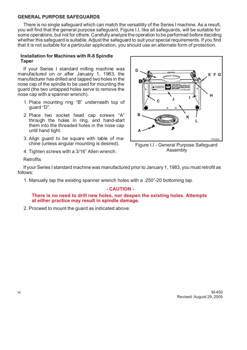
GENERAL PURPOSE SAFEGUARDS
There is no single safeguard which can match the versatility of the Series I machine. As a result,you will find that the general purpose safeguard, Figure I.I, like all safeguards, will be suitable for some operations, but not for others. Carefully analyze the operation to be performed before decidingwhether this safeguard is suitable. Adjust the safeguard to suit your special requirements. If you findthat it is not suitable for a particular application, you should use an alternate form of protection.
Installation for Machines with R-8 Spindle
Taper
If your Series I standard milling machine wasmanufactured on or after January 1, 1983, themanufacturer has drilled and tapped two holes in thenose cap of the spindle to be used for mounting theguard (the two untapped holes serve to remove thenose cap with a spanner wrench).
1. Place mounting ring “B” underneath top of guard “D”.
2. Place two socket head cap screws “A”
through the holes in ring, and hand-startthem into the threaded holes in the nose capuntil hand tight.
3. Align guard to be square with table of ma-chine (unless angular mounting is desired).
4. Tighten screws with a 3/16” Allen wrench.
Retrofits
If your Series I standard machine was manufactured prior to January 1, 1983, you must retrofit asfollows:
1. Manually tap the existing spanner wrench holes with a .250”-20 bottoming tap.
- CAUTION -
There is no need to drill new holes, nor deepen the existing holes. Attemptsat either practice may result in spindle damage.
2. Proceed to mount the guard as indicated above.
vi M-450Revised: August 29, 2005
Figure I.I - General Purpose Safeguard Assembly
E
BK
JC
I
L
A
D
H
F G
TP5262

7/28/2019 FullManual Manual Bridgeport
http://slidepdf.com/reader/full/fullmanual-manual-bridgeport 9/134
Machines with Erickson #30 Quick Change or Universal #200 Quick Change Spindles
If your milling machine attachment wasmanufactured after January 1, 1985 and has either an Erickson #30 or a Universal #200 quick changespindle, the manufacturer has drilled and tappedfour #8-32 holes in the nose cap of the spindle for mounting the guard.
ERICKSON SPINDLE
If the nose cap mounting ring has not beeninstalled, the following procedure will apply:
1. Remove the spindle locknut. This is done byremoving the long button head black finishscrew, which is normally left of the cad-mium-finished button head screw on thelocknut of the spindle. This will allow you tounscrew the locknut by turning it coun-ter-clockwise.
2. Place the nose cap mounting ring “O” up against the quill nose cap and install the four but-ton head cap screws “M”.
- NOTE -
The counterbored side of the nose cap mounting ring fits against the nose cap.
3. Lower the quill. Place the clamping ring “P” underneath the top of the guard “Q” and posi-tion the guard under the spindle.
4. Install the four socket head cap screws “N” through the nose cap mounting ring and threadthem into the clamping ring.
5. Align the front of the guard parallel to the front of the table. Tighten the screws clampingthe guard in position.
6. Reinstall the quick change locknut. Refer to assembly instructions.
If the nose cap mounting ring has been installed, omit steps 1, 2, and 6.
UNIVERSAL #200 QUICK CHANGE SPINDLES
The quick change locknut is not to be removed. To install the spindle safeguard, follow thepreceding steps listed above: 2, 3, 4 and 5.
M-450 viRevised: August 29, 2005
Figure I.II - Spindle Guard Assembly
N
P
TP5263
O
M
Q
7/28/2019 FullManual Manual Bridgeport
http://slidepdf.com/reader/full/fullmanual-manual-bridgeport 10/134
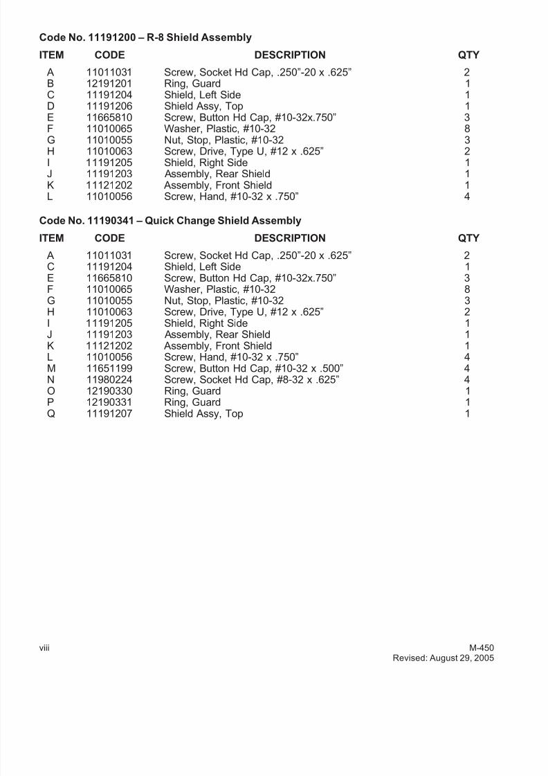
Code No. 11191200 – R-8 Shield Assembly
ITEM CODE DESCRIPTION QTY
A 11011031 Screw, Socket Hd Cap, .250”-20 x .625” 2B 12191201 Ring, Guard 1C 11191204 Shield, Left Side 1D 11191206 Shield Assy, Top 1E 11665810 Screw, Button Hd Cap, #10-32x.750” 3
F 11010065 Washer, Plastic, #10-32 8G 11010055 Nut, Stop, Plastic, #10-32 3H 11010063 Screw, Drive, Type U, #12 x .625” 2I 11191205 Shield, Right Side 1J 11191203 Assembly, Rear Shield 1K 11121202 Assembly, Front Shield 1L 11010056 Screw, Hand, #10-32 x .750” 4
Code No. 11190341 – Quick Change Shield Assembly
ITEM CODE DESCRIPTION QTY
A 11011031 Screw, Socket Hd Cap, .250”-20 x .625” 2
C 11191204 Shield, Left Side 1E 11665810 Screw, Button Hd Cap, #10-32x.750” 3F 11010065 Washer, Plastic, #10-32 8G 11010055 Nut, Stop, Plastic, #10-32 3H 11010063 Screw, Drive, Type U, #12 x .625” 2I 11191205 Shield, Right Side 1J 11191203 Assembly, Rear Shield 1K 11121202 Assembly, Front Shield 1L 11010056 Screw, Hand, #10-32 x .750” 4M 11651199 Screw, Button Hd Cap, #10-32 x .500” 4N 11980224 Screw, Socket Hd Cap, #8-32 x .625” 4O 12190330 Ring, Guard 1
P 12190331 Ring, Guard 1Q 11191207 Shield Assy, Top 1
viii M-450Revised: August 29, 2005

7/28/2019 FullManual Manual Bridgeport
http://slidepdf.com/reader/full/fullmanual-manual-bridgeport 11/134
- NOTES -
M-450 ix

7/28/2019 FullManual Manual Bridgeport
http://slidepdf.com/reader/full/fullmanual-manual-bridgeport 12/134
- NOTES -
x M-450
7/28/2019 FullManual Manual Bridgeport
http://slidepdf.com/reader/full/fullmanual-manual-bridgeport 13/134
Table of Contents
CHAPTER 1 - INSTALLATION
Uncrating . . . . . . . . . . . . . . . . . . . . . . . . . . . . . . . . . . . . 1-1
Shortages . . . . . . . . . . . . . . . . . . . . . . . . . . . . . . . . . . . . 1-1
Cleaning . . . . . . . . . . . . . . . . . . . . . . . . . . . . . . . . . . . . 1-1
Installation . . . . . . . . . . . . . . . . . . . . . . . . . . . . . . . . . . . 1-2Handles . . . . . . . . . . . . . . . . . . . . . . . . . . . . . . . . . . . 1-2Positioning Head Upright . . . . . . . . . . . . . . . . . . . . . . . . . . . 1-2
Handling . . . . . . . . . . . . . . . . . . . . . . . . . . . . . . . . . . . . 1-3Lifting the Machine . . . . . . . . . . . . . . . . . . . . . . . . . . . . 1-3
F o u n d a t i o n . . . . . . . . . . . . . . . . . . . . . . . . . . . . . . . . . . . 1 - 4Machine . . . . . . . . . . . . . . . . . . . . . . . . . . . . . . . . . . . 1-4
Tightening Sequence . . . . . . . . . . . . . . . . . . . . . . . . . . . 1-4Placing on Solid Foundation . . . . . . . . . . . . . . . . . . . . . . . . 1-4Leveling Machine . . . . . . . . . . . . . . . . . . . . . . . . . . . . . 1-5
Machine Power Supply . . . . . . . . . . . . . . . . . . . . . . . . . . . . . . 1-6Connecting the Power Supply . . . . . . . . . . . . . . . . . . . . . . . . . 1-6
Lubrication . . . . . . . . . . . . . . . . . . . . . . . . . . . . . . . . . . . 1-7
Initial Settings . . . . . . . . . . . . . . . . . . . . . . . . . . . . . . . . . . 1-8Head Controls . . . . . . . . . . . . . . . . . . . . . . . . . . . . . . . . 1-8
Alignment of Head for Fine Work . . . . . . . . . . . . . . . . . . . . . . 1-8Tightening Sequence . . . . . . . . . . . . . . . . . . . . . . . . . . . 1-8L u b r i c a t i o n . . . . . . . . . . . . . . . . . . . . . . . . . . . . . . . . 1 - 8
CHAPTER 2 - OPERATION
Head Controls . . . . . . . . . . . . . . . . . . . . . . . . . . . . . . . . . . 2-1High-Low Range Switch. . . . . . . . . . . . . . . . . . . . . . . . . . . . 2-2Variable Speed Dial. . . . . . . . . . . . . . . . . . . . . . . . . . . . . . 2-2Spindle Brake . . . . . . . . . . . . . . . . . . . . . . . . . . . . . . . . 2-3
Quill Feed Selector . . . . . . . . . . . . . . . . . . . . . . . . . . . . . . 2-3Quill Stop Knob . . . . . . . . . . . . . . . . . . . . . . . . . . . . . . . 2-4Micrometer Nut . . . . . . . . . . . . . . . . . . . . . . . . . . . . . . . . 2-4Feed Reverse Knob . . . . . . . . . . . . . . . . . . . . . . . . . . . . . 2-4Manual Feed Handwheel . . . . . . . . . . . . . . . . . . . . . . . . . . . 2-4Feed Control Lever . . . . . . . . . . . . . . . . . . . . . . . . . . . . . . 2-5Feed Control Overload Clutch . . . . . . . . . . . . . . . . . . . . . . . . . 2-5Quill . . . . . . . . . . . . . . . . . . . . . . . . . . . . . . . . . . . . . 2-5Spindle . . . . . . . . . . . . . . . . . . . . . . . . . . . . . . . . . . . 2-5Quill Lock . . . . . . . . . . . . . . . . . . . . . . . . . . . . . . . . . . 2-5
Quill Feed Handle . . . . . . . . . . . . . . . . . . . . . . . . . . . . . 2-6Power Feed Transmission Engagement Crank . . . . . . . . . . . . . . . . . 2-6
Hi-Neutral-Lo Lever . . . . . . . . . . . . . . . . . . . . . . . . . . . . . . 2-7Speed Change Handwheel . . . . . . . . . . . . . . . . . . . . . . . . . . 2-8Motor . . . . . . . . . . . . . . . . . . . . . . . . . . . . . . . . . . . . 2-9Drawbar . . . . . . . . . . . . . . . . . . . . . . . . . . . . . . . . . . . 2-9
M-450 1
7/28/2019 FullManual Manual Bridgeport
http://slidepdf.com/reader/full/fullmanual-manual-bridgeport 14/134
Operational Procedures . . . . . . . . . . . . . . . . . . . . . . . . . . . . 2-10Spindle Speed . . . . . . . . . . . . . . . . . . . . . . . . . . . . . . 2-10Back Gear (Low Speed) . . . . . . . . . . . . . . . . . . . . . . . . . . 2-10Direct Drive (High Speed) . . . . . . . . . . . . . . . . . . . . . . . . . 2-11Quill Feed . . . . . . . . . . . . . . . . . . . . . . . . . . . . . . . . 2-11
Head . . . . . . . . . . . . . . . . . . . . . . . . . . . . . . . . . . . . . . 2-13Operational Procedures . . . . . . . . . . . . . . . . . . . . . . . . . . . . 2-13
Spindle Brake . . . . . . . . . . . . . . . . . . . . . . . . . . . . . . . 2-13
Quill Sensitive Hand Feed . . . . . . . . . . . . . . . . . . . . . . . . . 2-13Machine. . . . . . . . . . . . . . . . . . . . . . . . . . . . . . . . . . . . . 2-14Operational Procedures . . . . . . . . . . . . . . . . . . . . . . . . . . . . 2-14
Swivel Belt Housing . . . . . . . . . . . . . . . . . . . . . . . . . . . . 2-14Swivel Turret . . . . . . . . . . . . . . . . . . . . . . . . . . . . . . . 2-14Move Ram Slide . . . . . . . . . . . . . . . . . . . . . . . . . . . . . 2-15Saddle Clamping . . . . . . . . . . . . . . . . . . . . . . . . . . . . . 2-15Table Clamping . . . . . . . . . . . . . . . . . . . . . . . . . . . . . . 2-16Knee Clamping . . . . . . . . . . . . . . . . . . . . . . . . . . . . . . 2-16
Power Feed Controls . . . . . . . . . . . . . . . . . . . . . . . . . . . . . . 2-17Operational Procedures . . . . . . . . . . . . . . . . . . . . . . . . . . . . 2-17
Variable Table Feeds . . . . . . . . . . . . . . . . . . . . . . . . . . . 2-17
Quick-Release Safety Handle . . . . . . . . . . . . . . . . . . . . . . . 2-17Variable Cross Slide Feed . . . . . . . . . . . . . . . . . . . . . . . . . 2-17
E-Head Controls . . . . . . . . . . . . . . . . . . . . . . . . . . . . . . . . . 2-18Operational Procedures . . . . . . . . . . . . . . . . . . . . . . . . . . . . 2-18
Head Swivel . . . . . . . . . . . . . . . . . . . . . . . . . . . . . . . 2-18To Change Speed . . . . . . . . . . . . . . . . . . . . . . . . . . . . . 2-19To Change Stroke . . . . . . . . . . . . . . . . . . . . . . . . . . . . . 2-19Clapper Box . . . . . . . . . . . . . . . . . . . . . . . . . . . . . . . 2-20
CHAPTER 3 - MAINTENANCE
2J-Head. . . . . . . . . . . . . . . . . . . . . . . . . . . . . . . . . . . . . 3-1
Maintenance Procedures . . . . . . . . . . . . . . . . . . . . . . . . . . . 3-1Motor Removal . . . . . . . . . . . . . . . . . . . . . . . . . . . . . . 3-1Drive Belt Replacement . . . . . . . . . . . . . . . . . . . . . . . . . . 3-2Timing Belt Replacement . . . . . . . . . . . . . . . . . . . . . . . . . 3-2Brake Shoe Replacement . . . . . . . . . . . . . . . . . . . . . . . . . 3-3
Head . . . . . . . . . . . . . . . . . . . . . . . . . . . . . . . . . . . . . . 3-4Maintenance Procedures . . . . . . . . . . . . . . . . . . . . . . . . . . . 3-4
Micro Feed Trip Assembly and Quill Removal . . . . . . . . . . . . . . . . 3-4Balance Spring Replacement . . . . . . . . . . . . . . . . . . . . . . . . 3-5Feed Trip Adjustment . . . . . . . . . . . . . . . . . . . . . . . . . . . 3-5Collet Aligning Screw Replacement . . . . . . . . . . . . . . . . . . . . . 3-6
Gib Strip Adjustment . . . . . . . . . . . . . . . . . . . . . . . . . . . . . . . 3-7
Maintenance Procedures . . . . . . . . . . . . . . . . . . . . . . . . . . . 3-7 Adjustment of Table Gib . . . . . . . . . . . . . . . . . . . . . . . . . . 3-7 Adjustment of Saddle And Knee Gibs . . . . . . . . . . . . . . . . . . . . 3-7 Adjustment of Knee Gib . . . . . . . . . . . . . . . . . . . . . . . . . . 3-8
Table Screw. . . . . . . . . . . . . . . . . . . . . . . . . . . . . . . . . . . 3-9Maintenance Procedures . . . . . . . . . . . . . . . . . . . . . . . . . . . 3-9
Backlash Adjustment . . . . . . . . . . . . . . . . . . . . . . . . . . . 3-9
2 M-450
7/28/2019 FullManual Manual Bridgeport
http://slidepdf.com/reader/full/fullmanual-manual-bridgeport 15/134
Cross Screw Assembly. . . . . . . . . . . . . . . . . . . . . . . . . . . . . . 3-10Maintenance Procedures . . . . . . . . . . . . . . . . . . . . . . . . . . . 3-10
Backlash Adjustment . . . . . . . . . . . . . . . . . . . . . . . . . . . 3-10
E-Head . . . . . . . . . . . . . . . . . . . . . . . . . . . . . . . . . . . . . 3-11Maintenance Procedures . . . . . . . . . . . . . . . . . . . . . . . . . . . 3-11
Changing the Gear Case Oil . . . . . . . . . . . . . . . . . . . . . . . . 3-11Removing Motor. . . . . . . . . . . . . . . . . . . . . . . . . . . . . . 3-12Changing Speed . . . . . . . . . . . . . . . . . . . . . . . . . . . . . 3-12
Removing Reduction Drive Unit or Ram. . . . . . . . . . . . . . . . . . . 3-13
CHAPTER 4 - PARTS LISTINGS
E-Head . . . . . . . . . . . . . . . . . . . . . . . . . . . . . . . . . . . . . 4-1
E-Head . . . . . . . . . . . . . . . . . . . . . . . . . . . . . . . . . . . . . 4-2
2J-Head Top Housing . . . . . . . . . . . . . . . . . . . . . . . . . . . . . . 4-5
2J-Head Top Assembly . . . . . . . . . . . . . . . . . . . . . . . . . . . . . 4-6
2J-Head Back Gear . . . . . . . . . . . . . . . . . . . . . . . . . . . . . . . 4-8
2J-HEAD BACK GEAR. . . . . . . . . . . . . . . . . . . . . . . . . . . . . . 4-9
J-Head Top Housing . . . . . . . . . . . . . . . . . . . . . . . . . . . . . . . 4-11
J-Head Top Housing . . . . . . . . . . . . . . . . . . . . . . . . . . . . . . . 4-12
2J- and J-Head Lower Housing . . . . . . . . . . . . . . . . . . . . . . . . . . 4-142J- and J-Head Lower Housing . . . . . . . . . . . . . . . . . . . . . . . . . . 4-15
Basic Machine. . . . . . . . . . . . . . . . . . . . . . . . . . . . . . . . . . 4-19
Basic Machine. . . . . . . . . . . . . . . . . . . . . . . . . . . . . . . . . . 4-20
Lead Screw Assembly . . . . . . . . . . . . . . . . . . . . . . . . . . . . . . 4-23
Lead Screw Assembly . . . . . . . . . . . . . . . . . . . . . . . . . . . . . . 4-24
Spray Mist . . . . . . . . . . . . . . . . . . . . . . . . . . . . . . . . . . . 4-25
Flood Coolant . . . . . . . . . . . . . . . . . . . . . . . . . . . . . . . . . . 4-26
Lubrication System . . . . . . . . . . . . . . . . . . . . . . . . . . . . . . . 4-27
Lubrication System . . . . . . . . . . . . . . . . . . . . . . . . . . . . . . . 4-28
Power Feed Y-Axis . . . . . . . . . . . . . . . . . . . . . . . . . . . . . . . 4-29
Power Feed Y-Axis . . . . . . . . . . . . . . . . . . . . . . . . . . . . . . . 4-30
Power Feed Y-Axis Control Box . . . . . . . . . . . . . . . . . . . . . . . . . 4-33
Power Feed Type (Servo Type) . . . . . . . . . . . . . . . . . . . . . . . . . . 4-34
6F Power Feed X-Axis . . . . . . . . . . . . . . . . . . . . . . . . . . . . . . 4-35
6F Power Feed X-Axis . . . . . . . . . . . . . . . . . . . . . . . . . . . . . . 4-36
8F Power Feed X-Axis . . . . . . . . . . . . . . . . . . . . . . . . . . . . . . 4-38
8F Power Feed X-Axis . . . . . . . . . . . . . . . . . . . . . . . . . . . . . . 4-39
8F Power Feed X-Axis . . . . . . . . . . . . . . . . . . . . . . . . . . . . . . 4-40
8F Power Feed X-Axis . . . . . . . . . . . . . . . . . . . . . . . . . . . . . . 4-42
8F Power Feed X-Axis . . . . . . . . . . . . . . . . . . . . . . . . . . . . . . 4-43
Power Feed X-Axis . . . . . . . . . . . . . . . . . . . . . . . . . . . . . . . 4-44
M-450 3
7/28/2019 FullManual Manual Bridgeport
http://slidepdf.com/reader/full/fullmanual-manual-bridgeport 16/134
Replacement Motor Assemblies Available . . . . . . . . . . . . . . . . . . . . . 4-45Motor Assembly J-Head 1 HP Unified without NFPA, Code No. 12190250 . . . . 4-45Motor Assembly J-Head Unified with NFPA. . . . . . . . . . . . . . . . . . . 4-45Motor Assembly 2J-Head 2 HP Unified without NFPA, Code No. 12550150. . . . 4-45Motor Assembly 2J-Head 2 HP Unified with NFPA . . . . . . . . . . . . . . . 4-46Motor Assembly 2J-Head 2 HP 575 Volts without NFPA, Code No. 12550020 . . 4-46Motor Assembly 2J-Head 2 HP 575 Volts with NFPA . . . . . . . . . . . . . . 4-46Replacement Motors Available. . . . . . . . . . . . . . . . . . . . . . . . . 4-46
Code No. 2203000 – M Milling Head – Spare Parts Kit . . . . . . . . . . . . . 4-46Code No. 2193000 – J Milling Head – Spare Parts Kit. . . . . . . . . . . . . . 4-47Code No. 2183000 – 2J Milling Head (1-1/2 HP) – Spare Parts Kit. . . . . . . . 4-47Code No. 2553000 – 2J Milling Head (2 HP) – Spare Parts Kit . . . . . . . . . 4-47Code No. 2062000 – Series I Standard Machine – Spare Parts Kit . . . . . . . . 4-48Lead Screws for Manually Operated Machines (without Keys) . . . . . . . . . . 4-48Lead Screws Available for Machines with Power Feeds (without Keys) . . . . . . 4-48
Metric Conversion Kits . . . . . . . . . . . . . . . . . . . . . . . . . . . . . . 4-49Code No. 2204000 – M Head, Metric Conversion Kit . . . . . . . . . . . . . . 4-49Code No. 2184000 – J- and 2J-Head, Metric Conversion Kit . . . . . . . . . . . 4-49Code No. 2064001 – Metric Conversion Kits . . . . . . . . . . . . . . . . . . 4-49Code No. 2064002 – Metric Conversion Kits . . . . . . . . . . . . . . . . . . 4-49
Code No. 2064003 – Metric Conversion Kits . . . . . . . . . . . . . . . . . . 4-506F Power Feed Field Conversion Kits for Machines without NFPA . . . . . . . . 4-50
CHAPTER 5 - SPECIFICATIONS
Machine. . . . . . . . . . . . . . . . . . . . . . . . . . . . . . . . . . . . . 5-1Principle Dimensions . . . . . . . . . . . . . . . . . . . . . . . . . . . . . 5-1Floor Plan Installation Layout . . . . . . . . . . . . . . . . . . . . . . . . . 5-2Machine Specifications . . . . . . . . . . . . . . . . . . . . . . . . . . . . 5-4
Head . . . . . . . . . . . . . . . . . . . . . . . . . . . . . . . . . . . . . . 5-5Milling Specifications . . . . . . . . . . . . . . . . . . . . . . . . . . . . . 5-5
2J-Head. . . . . . . . . . . . . . . . . . . . . . . . . . . . . . . . . . . . . 5-6General Speed Recommendations . . . . . . . . . . . . . . . . . . . . . . . 5-6Table of Cutting Speeds and Feeds . . . . . . . . . . . . . . . . . . . . . . 5-6
J-Head . . . . . . . . . . . . . . . . . . . . . . . . . . . . . . . . . . . . . 5-8
E-Head . . . . . . . . . . . . . . . . . . . . . . . . . . . . . . . . . . . . . 5-9
6F Power Feed . . . . . . . . . . . . . . . . . . . . . . . . . . . . . . . . . 5-10Schematic . . . . . . . . . . . . . . . . . . . . . . . . . . . . . . . . . . 5-106F Power Feed Circuit Board . . . . . . . . . . . . . . . . . . . . . . . . . 5-11
8F Power Feed . . . . . . . . . . . . . . . . . . . . . . . . . . . . . . . . . 5-12Schematic . . . . . . . . . . . . . . . . . . . . . . . . . . . . . . . . . . 5-128F Power Feed Circuit Board . . . . . . . . . . . . . . . . . . . . . . . . . 5-138F Power Feed Schematic . . . . . . . . . . . . . . . . . . . . . . . . . . 5-14
Parts . . . . . . . . . . . . . . . . . . . . . . . . . . . . . . . . . . . . . . 5-15
8F Power Feed Schematic . . . . . . . . . . . . . . . . . . . . . . . . . . 5-158F Power Feed Circuit Board . . . . . . . . . . . . . . . . . . . . . . . . . 5-168F Power Feed Circuit Board . . . . . . . . . . . . . . . . . . . . . . . . . 5-17
4 M-450
7/28/2019 FullManual Manual Bridgeport
http://slidepdf.com/reader/full/fullmanual-manual-bridgeport 17/134
CHAPTER 1 - INSTALLATION
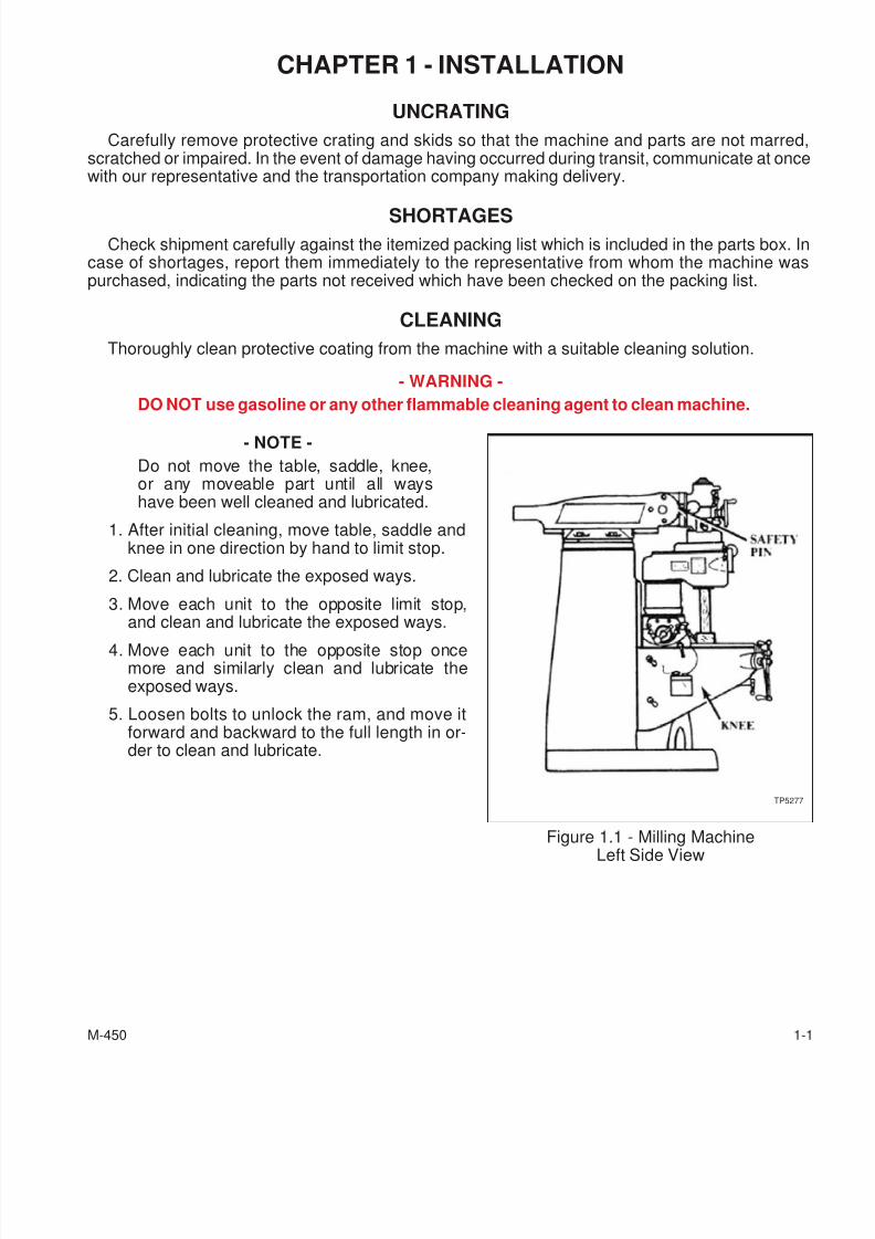
UNCRATING
Carefully remove protective crating and skids so that the machine and parts are not marredscratched or impaired. In the event of damage having occurred during transit, communicate at oncewith our representative and the transportation company making delivery.
SHORTAGESCheck shipment carefully against the itemized packing list which is included in the parts box. In
case of shortages, report them immediately to the representative from whom the machine waspurchased, indicating the parts not received which have been checked on the packing list.
CLEANING
Thoroughly clean protective coating from the machine with a suitable cleaning solution.
- WARNING -
DO NOT use gasoline or any other flammable cleaning agent to clean machine.
- NOTE -
Do not move the table, saddle, knee,or any moveable part until all wayshave been well cleaned and lubricated.
1. After initial cleaning, move table, saddle andknee in one direction by hand to limit stop.
2. Clean and lubricate the exposed ways.
3. Move each unit to the opposite limit stop,and clean and lubricate the exposed ways.
4. Move each unit to the opposite stop oncemore and similarly clean and lubricate theexposed ways.
5. Loosen bolts to unlock the ram, and move itforward and backward to the full length in or-der to clean and lubricate.
M-450 1-1
Figure 1.1 - Milling MachineLeft Side View
TP5277
7/28/2019 FullManual Manual Bridgeport
http://slidepdf.com/reader/full/fullmanual-manual-bridgeport 18/134
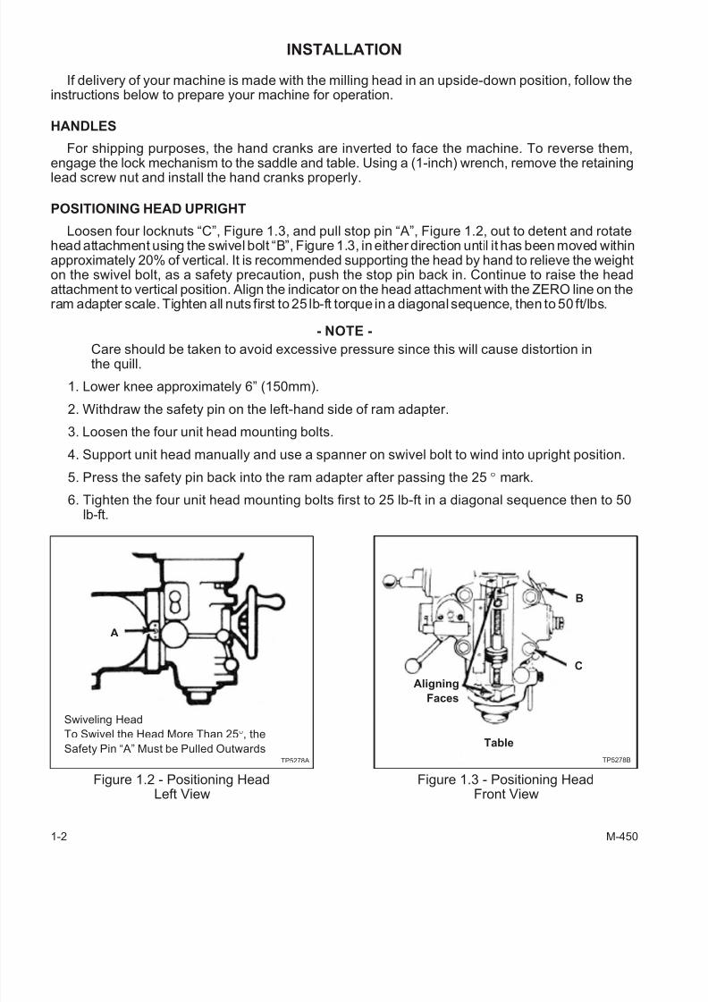
INSTALLATION
If delivery of your machine is made with the milling head in an upside-down position, follow theinstructions below to prepare your machine for operation.
HANDLES
For shipping purposes, the hand cranks are inverted to face the machine. To reverse them,engage the lock mechanism to the saddle and table. Using a (1-inch) wrench, remove the retaininglead screw nut and install the hand cranks properly.
POSITIONING HEAD UPRIGHT
Loosen four locknuts “C”, Figure 1.3, and pull stop pin “A”, Figure 1.2, out to detent and rotatehead attachment using the swivel bolt “B”, Figure 1.3, in either direction until it has been moved withinapproximately 20% of vertical. It is recommended supporting the head by hand to relieve the weighton the swivel bolt, as a safety precaution, push the stop pin back in. Continue to raise the headattachment to vertical position. Align the indicator on the head attachment with the ZERO line on theram adapter scale. Tighten all nuts first to 25 lb-ft torque in a diagonal sequence, then to 50 ft/lbs.
- NOTE -
Care should be taken to avoid excessive pressure since this will cause distortion inthe quill.
1. Lower knee approximately 6” (150mm).
2. Withdraw the safety pin on the left-hand side of ram adapter.
3. Loosen the four unit head mounting bolts.
4. Support unit head manually and use a spanner on swivel bolt to wind into upright position.
5. Press the safety pin back into the ram adapter after passing the 25° mark.
6. Tighten the four unit head mounting bolts first to 25 lb-ft in a diagonal sequence then to 50
lb-ft.
1-2 M-450
Figure 1.2 - Positioning HeadLeft View
Swiveling Head
To Swivel the Head More Than 25°, the
Safety Pin “A” Must be Pulled Outwards
A
TP5278A
Figure 1.3 - Positioning HeadFront View
B
Table
AligningFaces
C
TP5278B
7/28/2019 FullManual Manual Bridgeport
http://slidepdf.com/reader/full/fullmanual-manual-bridgeport 19/134
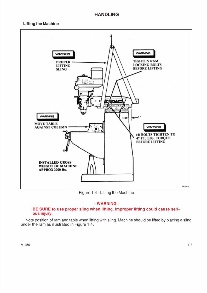
HANDLING
Lifting the Machine
- WARNING -
BE SURE to use proper sling when lifting. improper lifting could cause seri-ous injury.
Note position of ram and table when lifting with sling. Machine should be lifted by placing a slingunder the ram as illustrated in Figure 1.4.
M-450 1-3
Figure 1.4 - Lifting the Machine
TP5279
7/28/2019 FullManual Manual Bridgeport
http://slidepdf.com/reader/full/fullmanual-manual-bridgeport 20/134
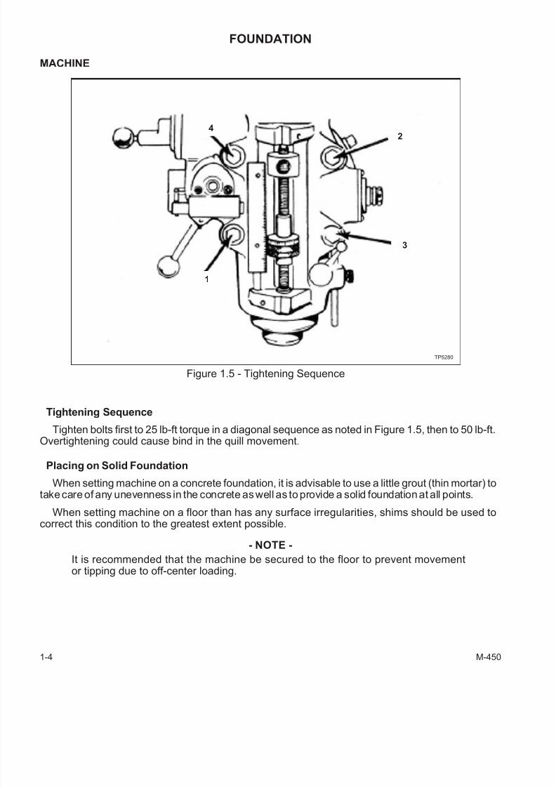
FOUNDATION
MACHINE
Tightening Sequence
Tighten bolts first to 25 lb-ft torque in a diagonal sequence as noted in Figure 1.5, then to 50 lb-ft.Overtightening could cause bind in the quill movement.
Placing on Solid Foundation
When setting machine on a concrete foundation, it is advisable to use a little grout (thin mortar) totake care of any unevenness in the concrete as well as to provide a solid foundation at all points.
When setting machine on a floor than has any surface irregularities, shims should be used tocorrect this condition to the greatest extent possible.
- NOTE -
It is recommended that the machine be secured to the floor to prevent movementor tipping due to off-center loading.
1-4 M-450
Figure 1.5 - Tightening Sequence
1
4
3
2
TP5280
7/28/2019 FullManual Manual Bridgeport
http://slidepdf.com/reader/full/fullmanual-manual-bridgeport 21/134
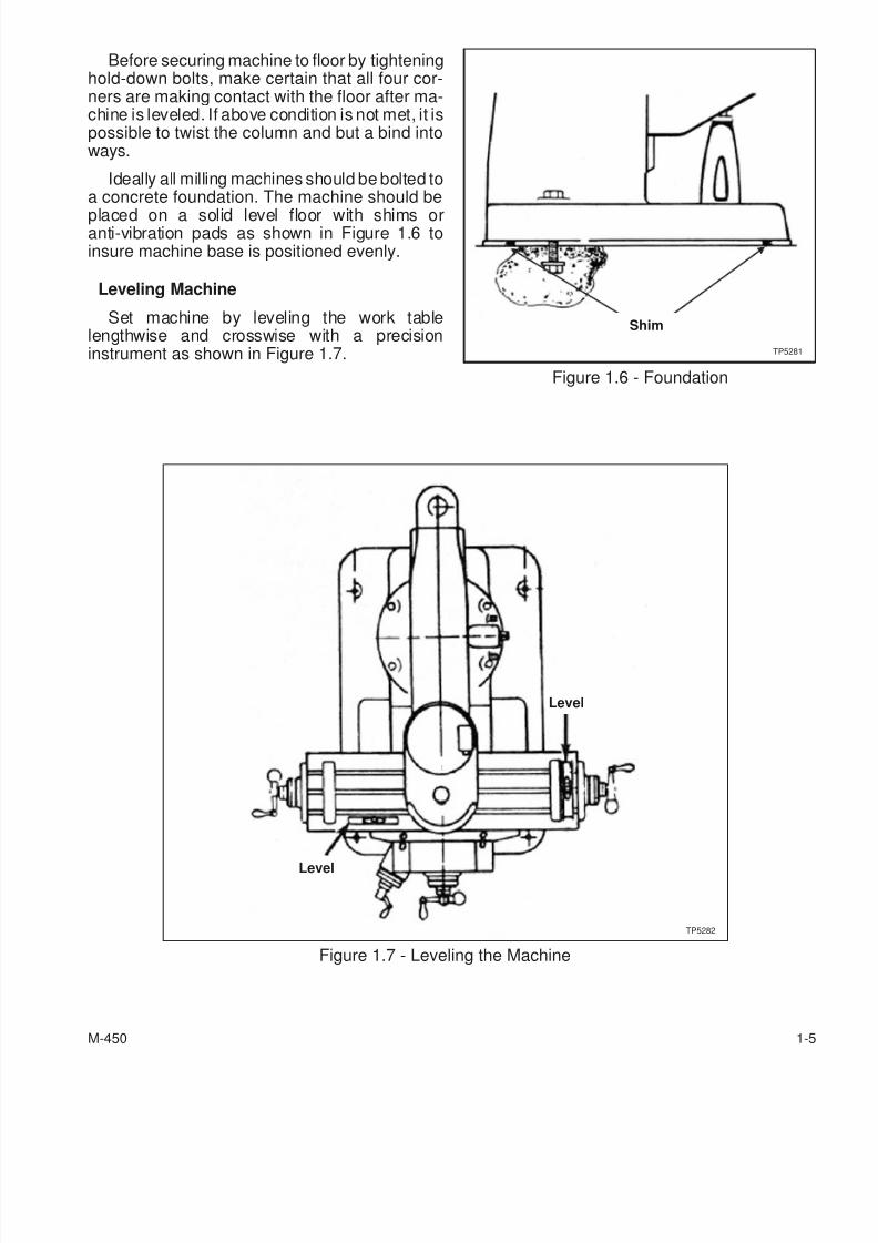
Before securing machine to floor by tighteninghold-down bolts, make certain that all four cor-ners are making contact with the floor after ma-chine is leveled. If above condition is not met, it ispossible to twist the column and but a bind intoways.
Ideally all milling machines should be bolted toa concrete foundation. The machine should be
placed on a solid level floor with shims oranti-vibration pads as shown in Figure 1.6 toinsure machine base is positioned evenly.
Leveling Machine
Set machine by leveling the work tablelengthwise and crosswise with a precisioninstrument as shown in Figure 1.7.
M-450 1-5
Figure 1.6 - Foundation
Shim
TP5281
Figure 1.7 - Leveling the Machine
Level
Level
TP5282

7/28/2019 FullManual Manual Bridgeport
http://slidepdf.com/reader/full/fullmanual-manual-bridgeport 22/134
MACHINE POWER SUPPLY
- WARNING -
MACHINE MUST be hooked up by a qualified electrician.
CONNECTING THE POWER SUPPLY
To connect the machine to the plant supply, have a qualified electrician proceed as follows:
1. Check required voltage against power supply to ensure that they are compatible.
2. Connect machine wiring to power supply making sure connection is in compliance withsafety regulations.
3. Check for correct spindle rotation. In the HIGH SPEED range, the spindle should rotateclockwise when viewed from the top of the machine.
- NOTE -
Drum switch and hi-neutral-lo lever must be in hi range when checking spindle ro-tation.
1-6 M-450
7/28/2019 FullManual Manual Bridgeport
http://slidepdf.com/reader/full/fullmanual-manual-bridgeport 23/134
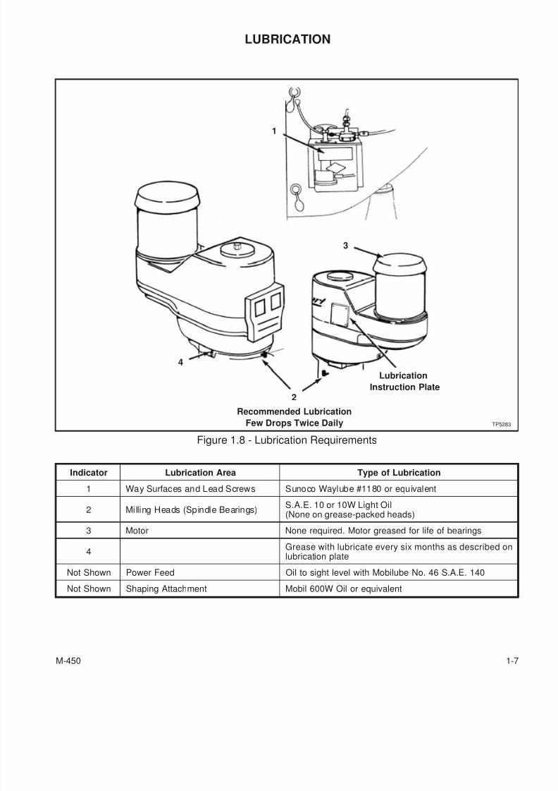
LUBRICATION
Indicator Lubrication Area Type of Lubrication
1 Way Surfaces and Lead Screws Sunoco Waylube #1180 or equivalent
2 Milling Heads (Spindle Bearings)S.A.E. 10 or 10W Light Oil(None on grease-packed heads)
3 Motor None required. Motor greased for life of bearings
4Grease with lubricate every six months as described onlubrication plate
Not Shown Power Feed Oil to sight level with Mobilube No. 46 S.A.E. 140
Not Shown Shaping Attachment Mobil 600W Oil or equivalent
M-450 1-7
Figure 1.8 - Lubrication Requirements
1
Lubrication
Instruction Plate
3
2
4
TP5283
Recommended Lubrication
Few Drops Twice Daily
7/28/2019 FullManual Manual Bridgeport
http://slidepdf.com/reader/full/fullmanual-manual-bridgeport 24/134
INITIAL SETTINGS
HEAD CONTROLS
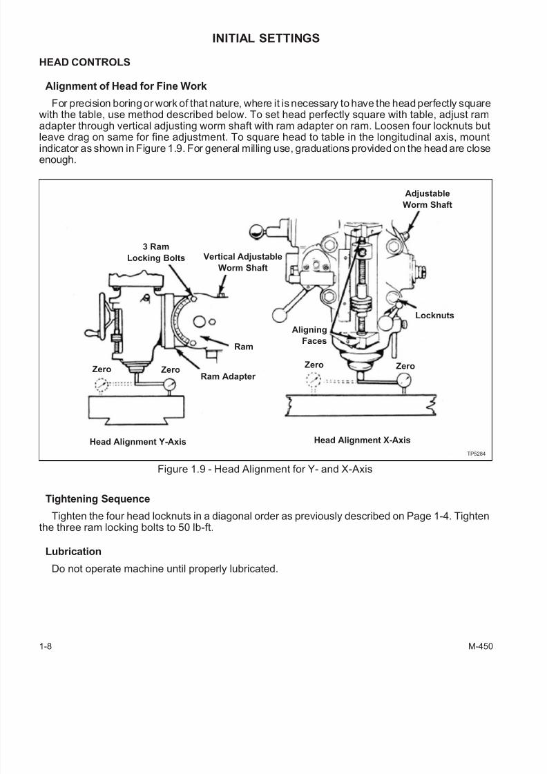
Alignment of Head for Fine Work
For precision boring or work of that nature, where it is necessary to have the head perfectly squarewith the table, use method described below. To set head perfectly square with table, adjust ramadapter through vertical adjusting worm shaft with ram adapter on ram. Loosen four locknuts butleave drag on same for fine adjustment. To square head to table in the longitudinal axis, mountindicator as shown in Figure 1.9. For general milling use, graduations provided on the head are closeenough.
Tightening Sequence
Tighten the four head locknuts in a diagonal order as previously described on Page 1-4. Tighten
the three ram locking bolts to 50 lb-ft.
Lubrication
Do not operate machine until properly lubricated.
1-8 M-450
Figure 1.9 - Head Alignment for Y- and X-Axis
Adjustable
Worm Shaft
Head Alignment Y-Axis Head Alignment X-Axis
Zero ZeroZero Zero
3 Ram
Locking Bolts Vertical Adjustable
Worm Shaft
Ram Adapter
Ram
Locknuts
Aligning
Faces
TP5284

7/28/2019 FullManual Manual Bridgeport
http://slidepdf.com/reader/full/fullmanual-manual-bridgeport 25/134
- NOTES -
M-450 1-9

7/28/2019 FullManual Manual Bridgeport
http://slidepdf.com/reader/full/fullmanual-manual-bridgeport 26/134
- NOTES -
1-10 M-450
7/28/2019 FullManual Manual Bridgeport
http://slidepdf.com/reader/full/fullmanual-manual-bridgeport 27/134
CHAPTER 2 - OPERATION
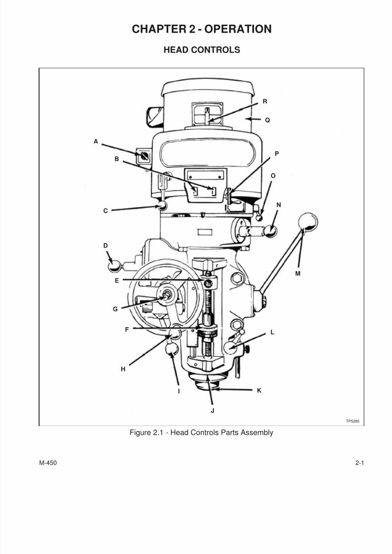
HEAD CONTROLS
M-450 2-1
Figure 2.1 - Head Controls Parts Assembly
A
N
O
P
Q
R
C
B
M
G
E
D
F
H
I
J
K
L
TP5285
7/28/2019 FullManual Manual Bridgeport
http://slidepdf.com/reader/full/fullmanual-manual-bridgeport 28/134
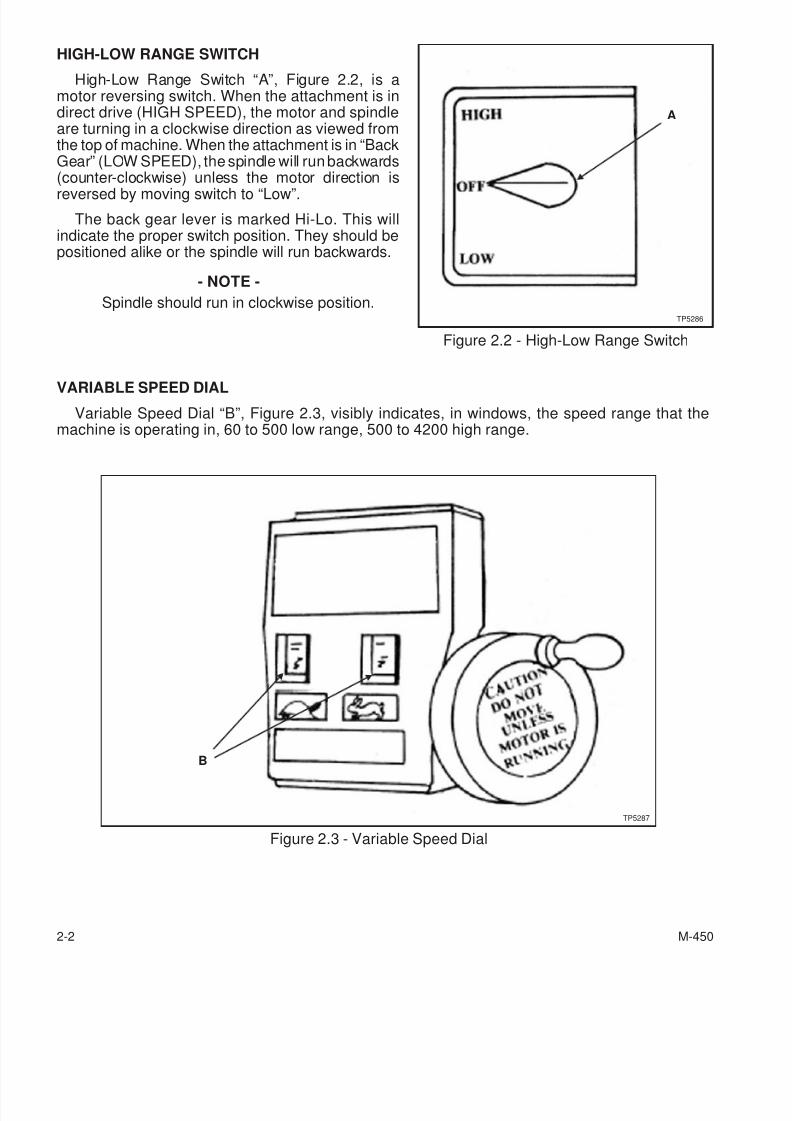
HIGH-LOW RANGE SWITCH
High-Low Range Switch “A”, Figure 2.2, is amotor reversing switch. When the attachment is indirect drive (HIGH SPEED), the motor and spindleare turning in a clockwise direction as viewed fromthe top of machine. When the attachment is in “BackGear” (LOW SPEED), the spindle will run backwards(counter-clockwise) unless the motor direction is
reversed by moving switch to “Low”.
The back gear lever is marked Hi-Lo. This willindicate the proper switch position. They should bepositioned alike or the spindle will run backwards.
- NOTE -
Spindle should run in clockwise position.
VARIABLE SPEED DIAL
Variable Speed Dial “B”, Figure 2.3, visibly indicates, in windows, the speed range that themachine is operating in, 60 to 500 low range, 500 to 4200 high range.
2-2 M-450
Figure 2.2 - High-Low Range Switch
A
TP5286
Figure 2.3 - Variable Speed Dial
TP5287
B
7/28/2019 FullManual Manual Bridgeport
http://slidepdf.com/reader/full/fullmanual-manual-bridgeport 29/134
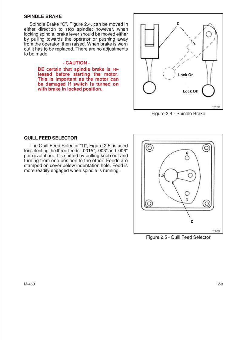
SPINDLE BRAKE
Spindle Brake “C”, Figure 2.4, can be moved ineither direction to stop spindle; however, whenlocking spindle, brake lever should be moved eitherby pulling towards the operator or pushing awayfrom the operator, then raised. When brake is wornout it has to be replaced. There are no adjustmentsto be made.
- CAUTION -
BE certain that spindle brake is re-leased before starting the motor.This is important as the motor canbe damaged if switch is turned onwith brake in locked position.
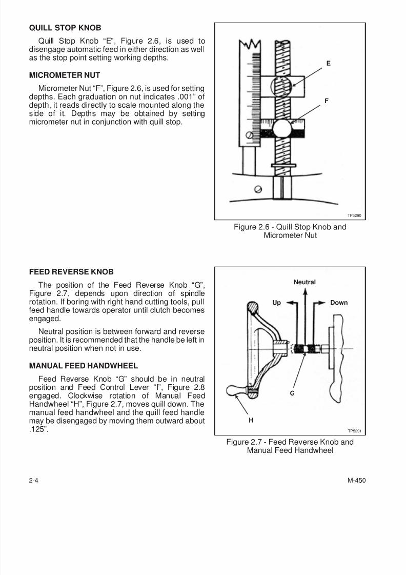
QUILL FEED SELECTOR
The Quill Feed Selector “D”, Figure 2.5, is usedfor selecting the three feeds: .0015”, .003” and .006”per revolution. It is shifted by pulling knob out andturning from one position to the other. Feeds arestamped on cover below indentation hole. Feed ismore readily engaged when spindle is running.
M-450 2-3
Figure 2.4 - Spindle Brake
Lock On
Lock Off
TP5288
C
Figure 2.5 - Quill Feed Selector
D
TP5289
7/28/2019 FullManual Manual Bridgeport
http://slidepdf.com/reader/full/fullmanual-manual-bridgeport 30/134
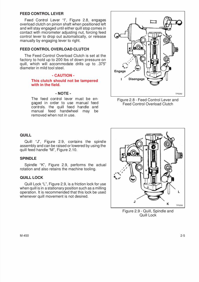
QUILL STOP KNOB
Quill Stop Knob “E”, Figure 2.6, is used todisengage automatic feed in either direction as wellas the stop point setting working depths.
MICROMETER NUT
Micrometer Nut “F”, Figure 2.6, is used for setting
depths. Each graduation on nut indicates .001” ofdepth, it reads directly to scale mounted along theside of it. Depths may be obtained by settingmicrometer nut in conjunction with quill stop.
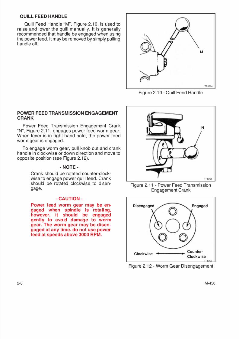
FEED REVERSE KNOB
The position of the Feed Reverse Knob “G”,
Figure 2.7, depends upon direction of spindlerotation. If boring with right hand cutting tools, pullfeed handle towards operator until clutch becomesengaged.
Neutral position is between forward and reverseposition. It is recommended that the handle be left inneutral position when not in use.
MANUAL FEED HANDWHEEL
Feed Reverse Knob “G” should be in neutralposition and Feed Control Lever “I”, Figure 2.8
engaged. Clockwise rotation of Manual FeedHandwheel “H”, Figure 2.7, moves quill down. Themanual feed handwheel and the quill feed handlemay be disengaged by moving them outward about.125”.
2-4 M-450
Figure 2.6 - Quill Stop Knob andMicrometer Nut
E
F
TP5290
Figure 2.7 - Feed Reverse Knob andManual Feed Handwheel
Neutral
G
Down
TP5291
Up
H
7/28/2019 FullManual Manual Bridgeport
http://slidepdf.com/reader/full/fullmanual-manual-bridgeport 31/134
FEED CONTROL LEVER
Feed Control Lever “I”, Figure 2.8, engagesoverload clutch on pinion shaft when positioned leftand will stay engaged until either quill stop comes incontact with micrometer adjusting nut, forcing feedcontrol lever to drop out automatically, or releasemanually by engaging lever to right.
FEED CONTROL OVERLOAD CLUTCH
The Feed Control Overload Clutch is set at thefactory to hold up to 200 lbs of down pressure onquill, which will accommodate drills up to .375”diameter in mild tool steel.
- CAUTION -
This clutch should not be tamperedwith in the field.
- NOTE -
The feed control lever must be en-gaged in order to use manual feedcontrols. the quill feed handle andmanual feed handwheel may beremoved when not in use.
QUILL
Quill “J”, Figure 2.9, contains the spindle
assembly and can be raised or lowered by using thequill feed handle “M”, Figure 2.10.
SPINDLE
Spindle “K”, Figure 2.9, performs the actualrotation and also retains the machine tooling.
QUILL LOCK
Quill Lock “L”, Figure 2.9, is a friction lock for usewhen quill is in a stationary position such as a milling
operation. It is recommended that this lock be usedwhenever quill movement is not desired.
M-450 2-5
Figure 2.8 - Feed Control Lever andFeed Control Overload Clutch
I
Engage
Disengage
TP5292
Figure 2.9 - Quill, Spindle andQuill Lock
J
L
TP5293K
7/28/2019 FullManual Manual Bridgeport
http://slidepdf.com/reader/full/fullmanual-manual-bridgeport 32/134
QUILL FEED HANDLE
Quill Feed Handle “M”, Figure 2.10, is used toraise and lower the quill manually. It is generallyrecommended that handle be engaged when usingthe power feed. It may be removed by simply pullinghandle off.
POWER FEED TRANSMISSION ENGAGEMENTCRANK
Power Feed Transmission Engagement Crank“N”, Figure 2.11, engages power feed worm gear.When lever is in right hand hole, the power feedworm gear is engaged.
To engage worm gear, pull knob out and crankhandle in clockwise or down direction and move toopposite position (see Figure 2.12).
- NOTE -
Crank should be rotated counter-clock-wise to engage power quill feed. Crankshould be rotated clockwise to disen-gage.
- CAUTION -
Power feed worm gear may be en-gaged when spindle is rotating,however, it should be engagedgently to avoid damage to wormgear. The worm gear may be disen-gaged at any time. do not use powerfeed at speeds above 3000 RPM.
2-6 M-450
Figure 2.10 - Quill Feed Handle
M
TP5294
Figure 2.11 - Power Feed TransmissionEngagement Crank
N
TP5295
Figure 2.12 - Worm Gear Disengagement
Disengaged Engaged
ClockwiseCounter-
ClockwiseTP5296
7/28/2019 FullManual Manual Bridgeport
http://slidepdf.com/reader/full/fullmanual-manual-bridgeport 33/134
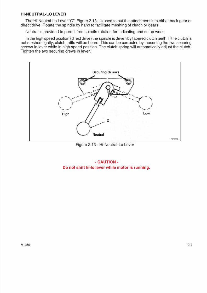
HI-NEUTRAL-LO LEVER
The Hi-Neutral-Lo Lever “O”, Figure 2.13, is used to put the attachment into either back gear odirect drive. Rotate the spindle by hand to facilitate meshing of clutch or gears.
Neutral is provided to permit free spindle rotation for indicating and setup work.
In the high speed position (direct drive) the spindle is driven by tapered clutch teeth. If the clutch isnot meshed tightly, clutch rattle will be heard. This can be corrected by loosening the two securingscrews in lever while in high speed position. The clutch spring will automatically adjust the clutch.
Tighten the two securing crews in lever.
- CAUTION -
Do not shift hi-lo lever while motor is running.
M-450 2-7
Figure 2.13 - Hi-Neutral-Lo Lever
Neutral
High Low
Securing Screws
TP5297
O
7/28/2019 FullManual Manual Bridgeport
http://slidepdf.com/reader/full/fullmanual-manual-bridgeport 34/134
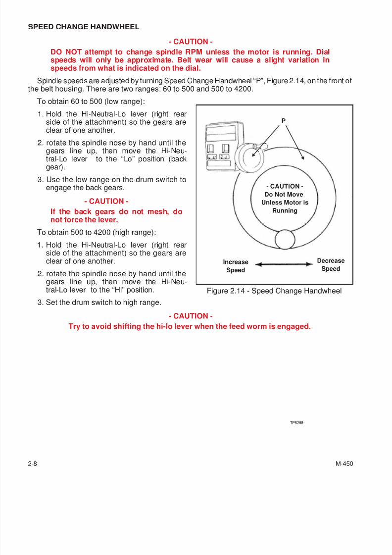
SPEED CHANGE HANDWHEEL
- CAUTION -
DO NOT attempt to change spindle RPM unless the motor is running. Dialspeeds will only be approximate. Belt wear will cause a slight variation inspeeds from what is indicated on the dial.
Spindle speeds are adjusted by turning Speed Change Handwheel “P”, Figure 2.14, on the front ofthe belt housing. There are two ranges: 60 to 500 and 500 to 4200.
To obtain 60 to 500 (low range):
1. Hold the Hi-Neutral-Lo lever (right rearside of the attachment) so the gears areclear of one another.
2. rotate the spindle nose by hand until thegears line up, then move the Hi-Neu-tral-Lo lever to the “Lo” position (backgear).
3. Use the low range on the drum switch to
engage the back gears.- CAUTION -
If the back gears do not mesh, donot force the lever.
To obtain 500 to 4200 (high range):
1. Hold the Hi-Neutral-Lo lever (right rearside of the attachment) so the gears areclear of one another.
2. rotate the spindle nose by hand until the
gears line up, then move the Hi-Neu-tral-Lo lever to the “Hi” position.
3. Set the drum switch to high range.
- CAUTION -
Try to avoid shifting the hi-lo lever when the feed worm is engaged.
2-8 M-450
Figure 2.14 - Speed Change Handwheel
- CAUTION -
Do Not Move
Unless Motor is
Running
Increase
Speed
Decrease
Speed
P
TP5298
7/28/2019 FullManual Manual Bridgeport
http://slidepdf.com/reader/full/fullmanual-manual-bridgeport 35/134
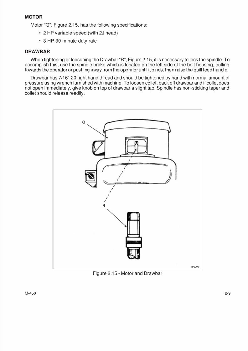
MOTOR
Motor “Q”, Figure 2.15, has the following specifications:
• 2 HP variable speed (with 2J head)
• 3 HP 30 minute duty rate
DRAWBAR
When tightening or loosening the Drawbar “R”, Figure 2.15, it is necessary to lock the spindle. Toaccomplish this, use the spindle brake which is located on the left side of the belt housing, pullingtowards the operator or pushing away from the operator until it binds, then raise the quill feed handle.
Drawbar has 7/16”-20 right hand thread and should be tightened by hand with normal amount ofpressure using wrench furnished with machine. To loosen collet, back off drawbar and if collet doesnot open immediately, give knob on top of drawbar a slight tap. Spindle has non-sticking taper andcollet should release readily.
M-450 2-9
Figure 2.15 - Motor and Drawbar
TP5299
Q
R
7/28/2019 FullManual Manual Bridgeport
http://slidepdf.com/reader/full/fullmanual-manual-bridgeport 36/134
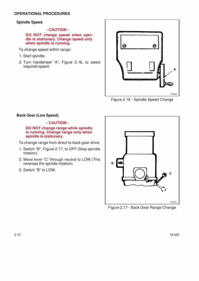
OPERATIONAL PROCEDURES
Spindle Speed
- CAUTION -
DO NOT change speed when spin-dle is stationary. Change speed onlywhen spindle is running.
To change speed within range:
1. Start spindle.
2. Turn handwheel “A”, Figure 2.16, to selectrequired speed.
Back Gear (Low Speed)
- CAUTION -
DO NOT change range while spindleis running. Change range only whenspindle is stationary.
To change range from direct to back gear drive:1. Switch “B”, Figure 2.17, to OFF (Stop spindle
rotation).
2. Move lever “C” through neutral to LOW (Thisreverses the spindle rotation).
3. Switch “B” to LOW.
2-10 M-450
Figure 2.16 - Spindle Speed Change
A
TP5300
Figure 2.17 - Back Gear Range Change
C
B
TP5301
7/28/2019 FullManual Manual Bridgeport
http://slidepdf.com/reader/full/fullmanual-manual-bridgeport 37/134
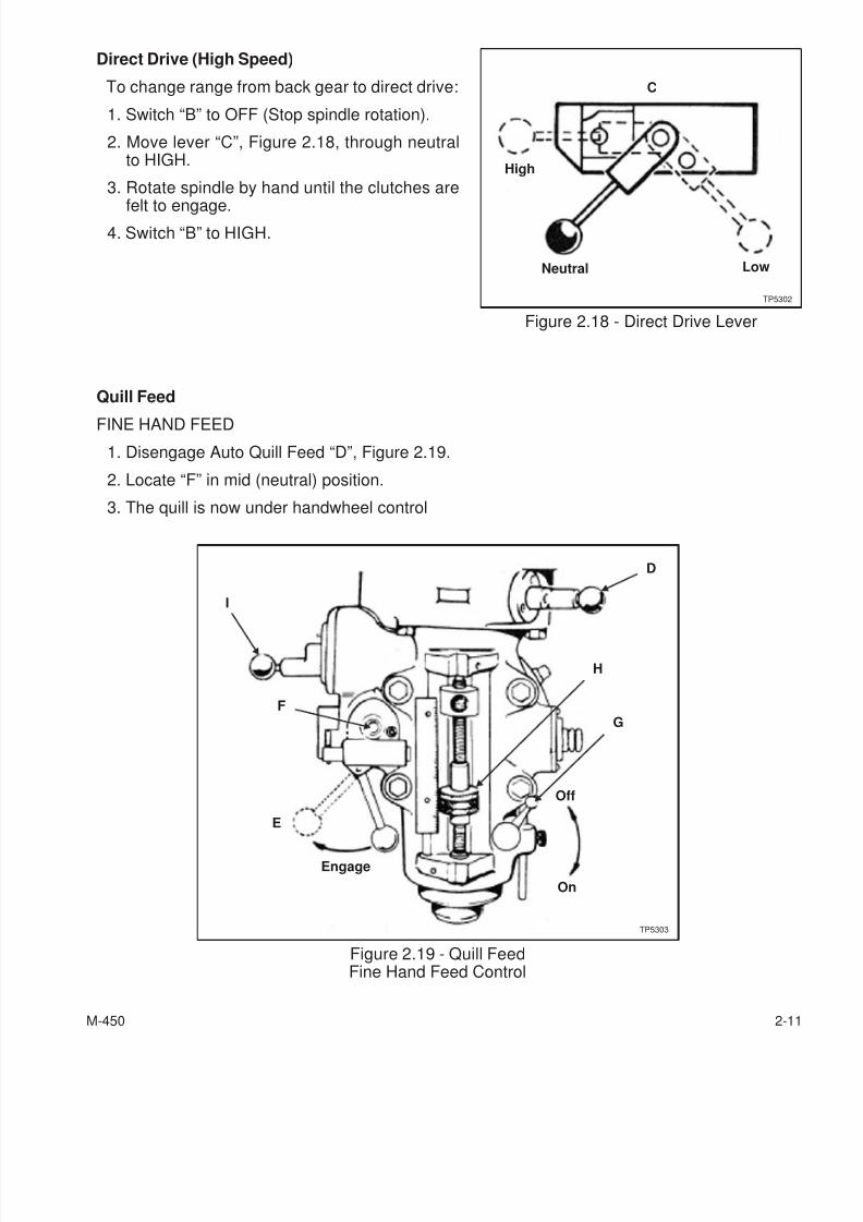
Direct Drive (High Speed)
To change range from back gear to direct drive:
1. Switch “B” to OFF (Stop spindle rotation).
2. Move lever “C”, Figure 2.18, through neutralto HIGH.
3. Rotate spindle by hand until the clutches are
felt to engage.4. Switch “B” to HIGH.
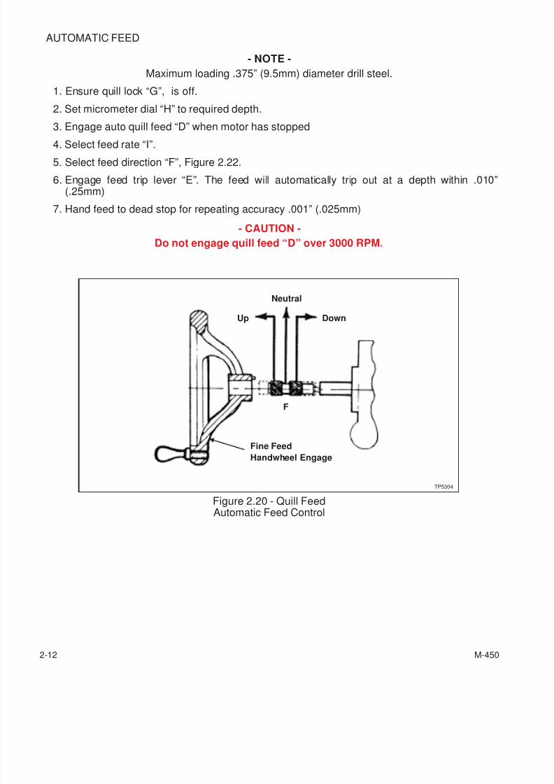
Quill Feed
FINE HAND FEED
1. Disengage Auto Quill Feed “D”, Figure 2.19.
2. Locate “F” in mid (neutral) position.
3. The quill is now under handwheel control
M-450 2-11
Figure 2.18 - Direct Drive Lever
High
C
Neutral Low
TP5302
Figure 2.19 - Quill FeedFine Hand Feed Control
E
F
I
D
H
G
Off
On
Engage
TP5303
7/28/2019 FullManual Manual Bridgeport
http://slidepdf.com/reader/full/fullmanual-manual-bridgeport 38/134
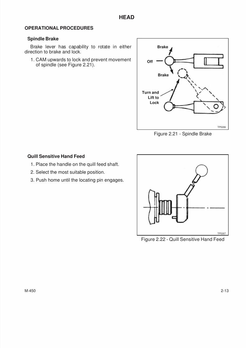
AUTOMATIC FEED
- NOTE -
Maximum loading .375” (9.5mm) diameter drill steel.
1. Ensure quill lock “G”, is off.
2. Set micrometer dial “H” to required depth.
3. Engage auto quill feed “D” when motor has stopped
4. Select feed rate “I”.
5. Select feed direction “F”, Figure 2.22.
6. Engage feed trip lever “E”. The feed will automatically trip out at a depth within .010”(.25mm)
7. Hand feed to dead stop for repeating accuracy .001” (.025mm)
- CAUTION -
Do not engage quill feed “D” over 3000 RPM.
2-12 M-450
Figure 2.20 - Quill FeedAutomatic Feed Control
F
Up
Neutral
Down
Fine Feed
Handwheel Engage
TP5304
7/28/2019 FullManual Manual Bridgeport
http://slidepdf.com/reader/full/fullmanual-manual-bridgeport 39/134
HEAD
OPERATIONAL PROCEDURES
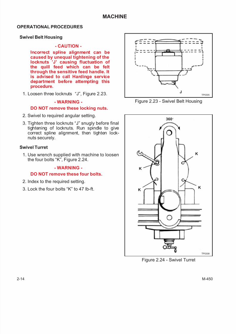
Spindle Brake
Brake lever has capability to rotate in eitherdirection to brake and lock.
1. CAM upwards to lock and prevent movementof spindle (see Figure 2.21).
Quill Sensitive Hand Feed
1. Place the handle on the quill feed shaft.
2. Select the most suitable position.
3. Push home until the locating pin engages.
M-450 2-13
Figure 2.21 - Spindle Brake
Brake
Brake
Off
Turn and
Lift to
Lock
TP5306
Figure 2.22 - Quill Sensitive Hand Feed
TP5307
7/28/2019 FullManual Manual Bridgeport
http://slidepdf.com/reader/full/fullmanual-manual-bridgeport 40/134
MACHINE
OPERATIONAL PROCEDURES
Swivel Belt Housing
- CAUTION -
Incorrect spline alignment can be
caused by unequal tightening of thelocknuts ’J’ causing fluctuation of the quill feed which can be feltthrough the sensitive feed handle. Itis advised to call Hardinge servicedepartment before attempting thisprocedure.
1. Loosen three locknuts “J”, Figure 2.23.
- WARNING -
DO NOT remove these locking nuts.
2. Swivel to required angular setting.
3. Tighten three locknuts “J” snugly before finaltightening of locknuts. Run spindle to givecorrect spline alignment, then tighten lock-nuts securely.
Swivel Turret
1. Use wrench supplied with machine to loosenthe four bolts “K”, Figure 2.24.
- WARNING -
DO NOT remove these four bolts.
2. Index to the required setting.
3. Lock the four bolts “K” to 47 lb-ft.
2-14 M-450
Figure 2.23 - Swivel Belt Housing
TP5305J
Figure 2.24 - Swivel Turret
360°
K
KK
K
TP5308
7/28/2019 FullManual Manual Bridgeport
http://slidepdf.com/reader/full/fullmanual-manual-bridgeport 41/134
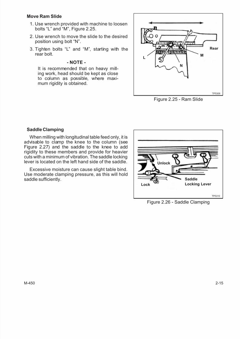
Move Ram Slide
1. Use wrench provided with machine to loosenbolts “L” and “M”, Figure 2.25.
2. Use wrench to move the slide to the desiredposition using bolt “N”.
3. Tighten bolts “L” and “M”, starting with therear bolt.
- NOTE -
It is recommended that on heavy mill-ing work, head should be kept as closeto column as possible, where maxi-mum rigidity is obtained.
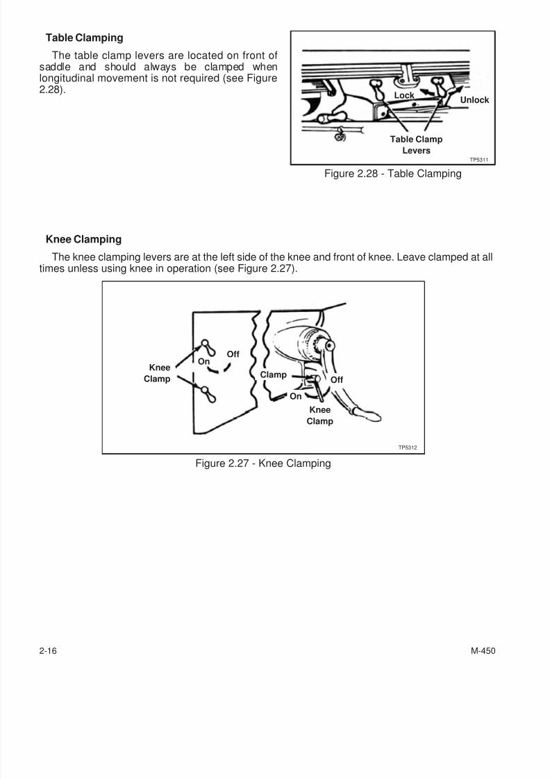
Saddle Clamping
When milling with longitudinal table feed only, it isadvisable to clamp the knee to the column (seeFigure 2.27) and the saddle to the knee to addrigidity to these members and provide for heavier cuts with a minimum of vibration. The saddle lockinglever is located on the left hand side of the saddle.
Excessive moisture can cause slight table bind.
Use moderate clamping pressure, as this will holdsaddle sufficiently.
M-450 2-15
Figure 2.25 - Ram Slide
TP5309
L
N
M
Rear
Figure 2.26 - Saddle Clamping
TP5310
Unlock
Lock
Saddle
Locking Lever
7/28/2019 FullManual Manual Bridgeport
http://slidepdf.com/reader/full/fullmanual-manual-bridgeport 42/134
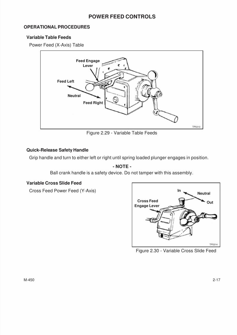
Table Clamping
The table clamp levers are located on front ofsaddle and should always be clamped whenlongitudinal movement is not required (see Figure2.28).
Knee Clamping
The knee clamping levers are at the left side of the knee and front of knee. Leave clamped at all
times unless using knee in operation (see Figure 2.27).
2-16 M-450
Figure 2.27 - Knee Clamping
Knee
Clamp
OnOff
Clamp
Knee
Clamp
Off
On
TP5312
Figure 2.28 - Table Clamping
UnlockLock
Table Clamp
LeversTP5311
7/28/2019 FullManual Manual Bridgeport
http://slidepdf.com/reader/full/fullmanual-manual-bridgeport 43/134
POWER FEED CONTROLS
OPERATIONAL PROCEDURES
Variable Table Feeds
Power Feed (X-Axis) Table
Quick-Release Safety Handle
Grip handle and turn to either left or right until spring loaded plunger engages in position.
- NOTE -
Ball crank handle is a safety device. Do not tamper with this assembly.
Variable Cross Slide Feed
Cross Feed Power Feed (Y-Axis)
M-450 2-17
Figure 2.29 - Variable Table Feeds
Feed Engage
Lever
TP5313
Feed Left
Feed Right
Neutral
Figure 2.30 - Variable Cross Slide Feed
TP5314
NeutralIn
OutCross Feed
Engage Lever
7/28/2019 FullManual Manual Bridgeport
http://slidepdf.com/reader/full/fullmanual-manual-bridgeport 44/134
E-HEAD CONTROLS
OPERATIONAL PROCEDURES
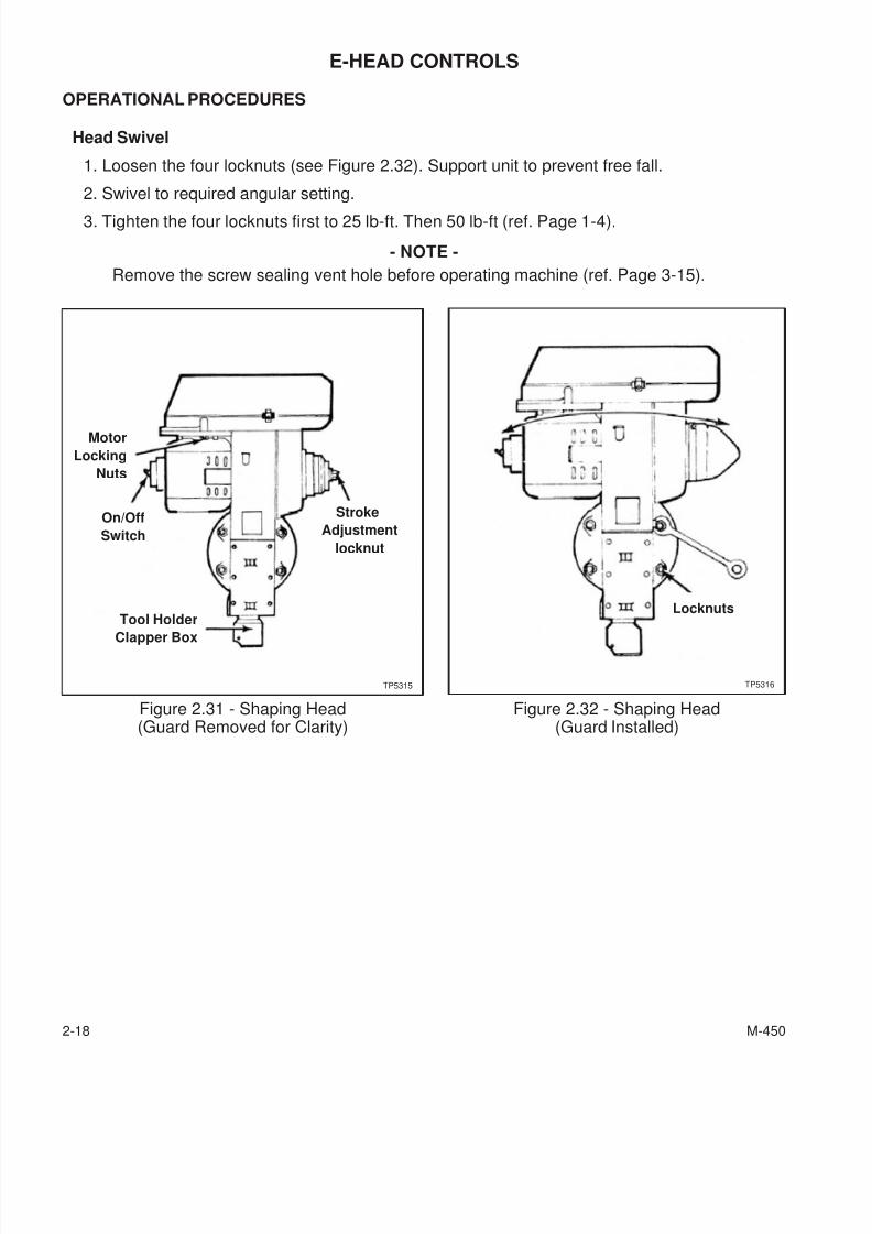
Head Swivel
1. Loosen the four locknuts (see Figure 2.32). Support unit to prevent free fall.
2. Swivel to required angular setting.
3. Tighten the four locknuts first to 25 lb-ft. Then 50 lb-ft (ref. Page 1-4).
- NOTE -
Remove the screw sealing vent hole before operating machine (ref. Page 3-15).
2-18 M-450
Figure 2.31 - Shaping Head(Guard Removed for Clarity)
Motor
Locking
Nuts
Stroke
Adjustment
locknut
On/Off
Switch
Tool Holder
Clapper Box
TP5315
Figure 2.32 - Shaping Head(Guard Installed)
TP5316
Locknuts
7/28/2019 FullManual Manual Bridgeport
http://slidepdf.com/reader/full/fullmanual-manual-bridgeport 45/134
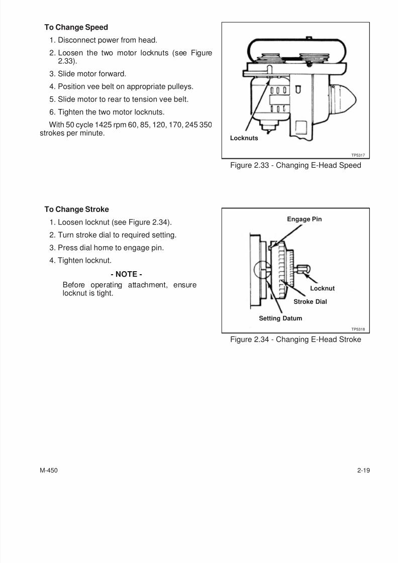
To Change Speed
1. Disconnect power from head.
2. Loosen the two motor locknuts (see Figure2.33).
3. Slide motor forward.
4. Position vee belt on appropriate pulleys.
5. Slide motor to rear to tension vee belt.
6. Tighten the two motor locknuts.
With 50 cycle 1425 rpm 60, 85, 120, 170, 245 350strokes per minute.
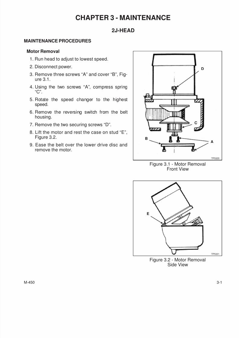
To Change Stroke
1. Loosen locknut (see Figure 2.34).
2. Turn stroke dial to required setting.
3. Press dial home to engage pin.
4. Tighten locknut.
- NOTE -
Before operating attachment, ensurelocknut is tight.
M-450 2-19
Figure 2.33 - Changing E-Head Speed
Locknuts
TP5317
Figure 2.34 - Changing E-Head Stroke
Engage Pin
Locknut
Stroke Dial
Setting Datum
TP5318

7/28/2019 FullManual Manual Bridgeport
http://slidepdf.com/reader/full/fullmanual-manual-bridgeport 46/134
Clapper Box
To Swivel Clapper Box:
1. Loosen the two set screws “O”, Figure 2.35.
2. Rotate to the required angular setting.
3. Tighten the two set screws “O”.
Tool Relief
1. Loosen set screw “P”.
The tool will now have automatic relief on thereturn stroke.
2-20 M-450
Figure 2.35 - Swiveling E-HeadClapper Box
TP5319
P
O
Rear View

7/28/2019 FullManual Manual Bridgeport
http://slidepdf.com/reader/full/fullmanual-manual-bridgeport 47/134
- NOTES -
M-450 2-21

7/28/2019 FullManual Manual Bridgeport
http://slidepdf.com/reader/full/fullmanual-manual-bridgeport 48/134
- NOTES -
2-22 M-450
7/28/2019 FullManual Manual Bridgeport
http://slidepdf.com/reader/full/fullmanual-manual-bridgeport 49/134
CHAPTER 3 - MAINTENANCE
2J-HEAD
MAINTENANCE PROCEDURES
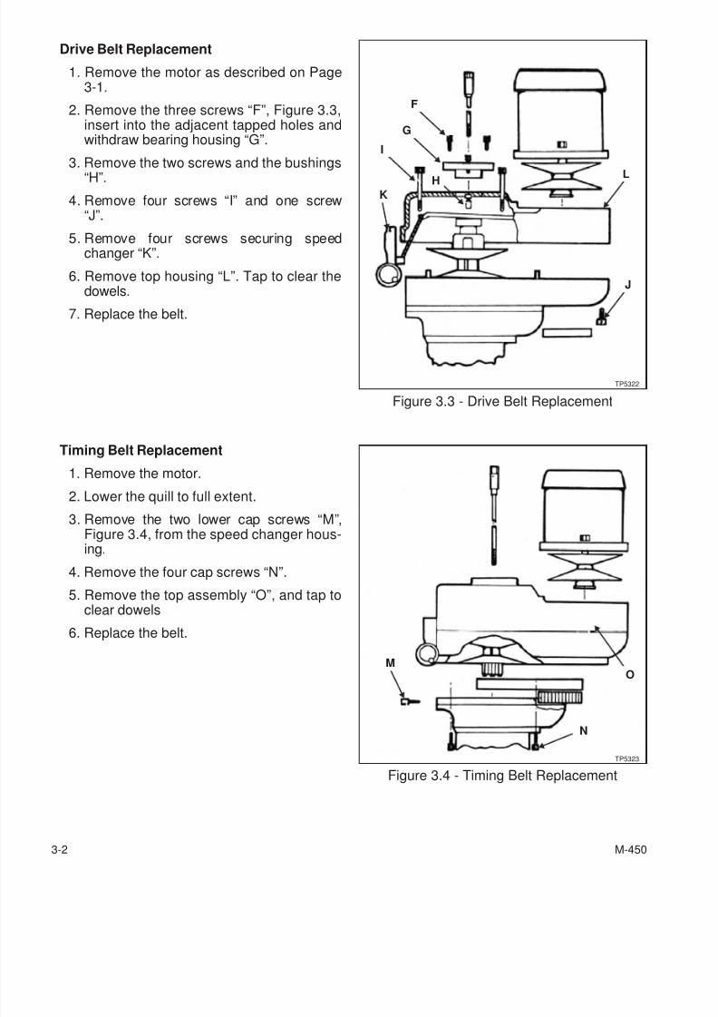
Motor Removal
1. Run head to adjust to lowest speed.
2. Disconnect power.
3. Remove three screws “A” and cover “B”, Fig-ure 3.1.
4. Using the two screws “A”, compress spring“C”.
5. Rotate the speed changer to the highestspeed.
6. Remove the reversing switch from the belt
housing.
7. Remove the two securing screws “D”.
8. Lift the motor and rest the case on stud “E”,Figure 3.2.
9. Ease the belt over the lower drive disc andremove the motor.
M-450 3-1
Figure 3.1 - Motor RemovalFront View
D
TP5320
C
AB
Figure 3.2 - Motor RemovalSide View
TP5321
E
7/28/2019 FullManual Manual Bridgeport
http://slidepdf.com/reader/full/fullmanual-manual-bridgeport 50/134
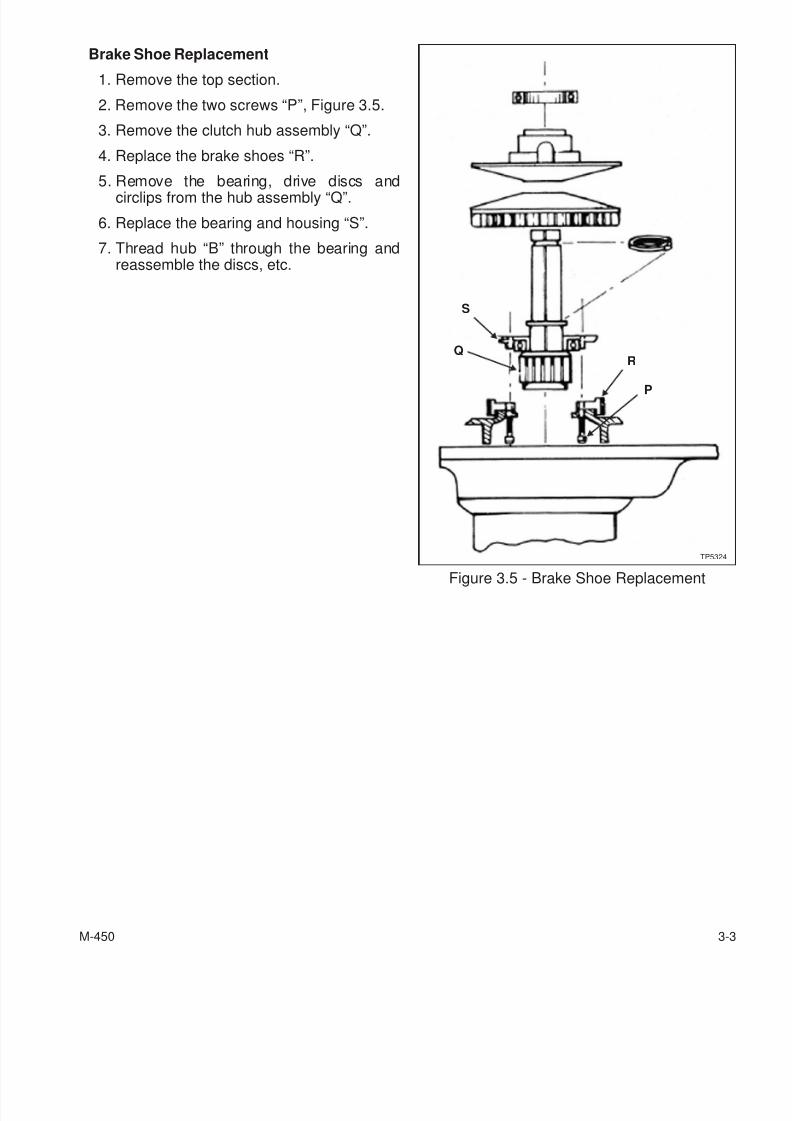
Drive Belt Replacement
1. Remove the motor as described on Page3-1.
2. Remove the three screws “F”, Figure 3.3,insert into the adjacent tapped holes andwithdraw bearing housing “G”.
3. Remove the two screws and the bushings
“H”.
4. Remove four screws “I” and one screw“J”.
5. Remove four screws securing speedchanger “K”.
6. Remove top housing “L”. Tap to clear thedowels.
7. Replace the belt.
Timing Belt Replacement
1. Remove the motor.
2. Lower the quill to full extent.
3. Remove the two lower cap screws “M”,Figure 3.4, from the speed changer hous-ing.
4. Remove the four cap screws “N”.
5. Remove the top assembly “O”, and tap toclear dowels
6. Replace the belt.
3-2 M-450
Figure 3.3 - Drive Belt Replacement
TP5322
F
G
I
K
H L
J
Figure 3.4 - Timing Belt Replacement
N
TP5323
MO
7/28/2019 FullManual Manual Bridgeport
http://slidepdf.com/reader/full/fullmanual-manual-bridgeport 51/134
Brake Shoe Replacement
1. Remove the top section.
2. Remove the two screws “P”, Figure 3.5.
3. Remove the clutch hub assembly “Q”.
4. Replace the brake shoes “R”.
5. Remove the bearing, drive discs andcirclips from the hub assembly “Q”.
6. Replace the bearing and housing “S”.
7. Thread hub “B” through the bearing andreassemble the discs, etc.
M-450 3-3
Figure 3.5 - Brake Shoe Replacement
TP5324
Q
S
R
P
7/28/2019 FullManual Manual Bridgeport
http://slidepdf.com/reader/full/fullmanual-manual-bridgeport 52/134
HEAD
MAINTENANCE PROCEDURES
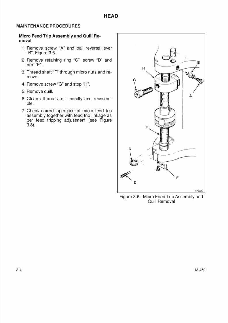
Micro Feed Trip Assembly and Quill Re-moval
1. Remove screw “A” and ball reverse lever“B”, Figure 3.6.
2. Remove retaining ring “C”, screw “D” andarm “E”.
3. Thread shaft “F” through micro nuts and re-move.
4. Remove screw “G” and stop “H”.
5. Remove quill.
6. Clean all areas, oil liberally and reassem-ble.
7. Check correct operation of micro feed tripassembly together with feed trip linkage asper feed tripping adjustment (see Figure3.8).
3-4 M-450
Figure 3.6 - Micro Feed Trip Assembly andQuill Removal
TP5325
G
H
B
A
F
C
E
D
7/28/2019 FullManual Manual Bridgeport
http://slidepdf.com/reader/full/fullmanual-manual-bridgeport 53/134
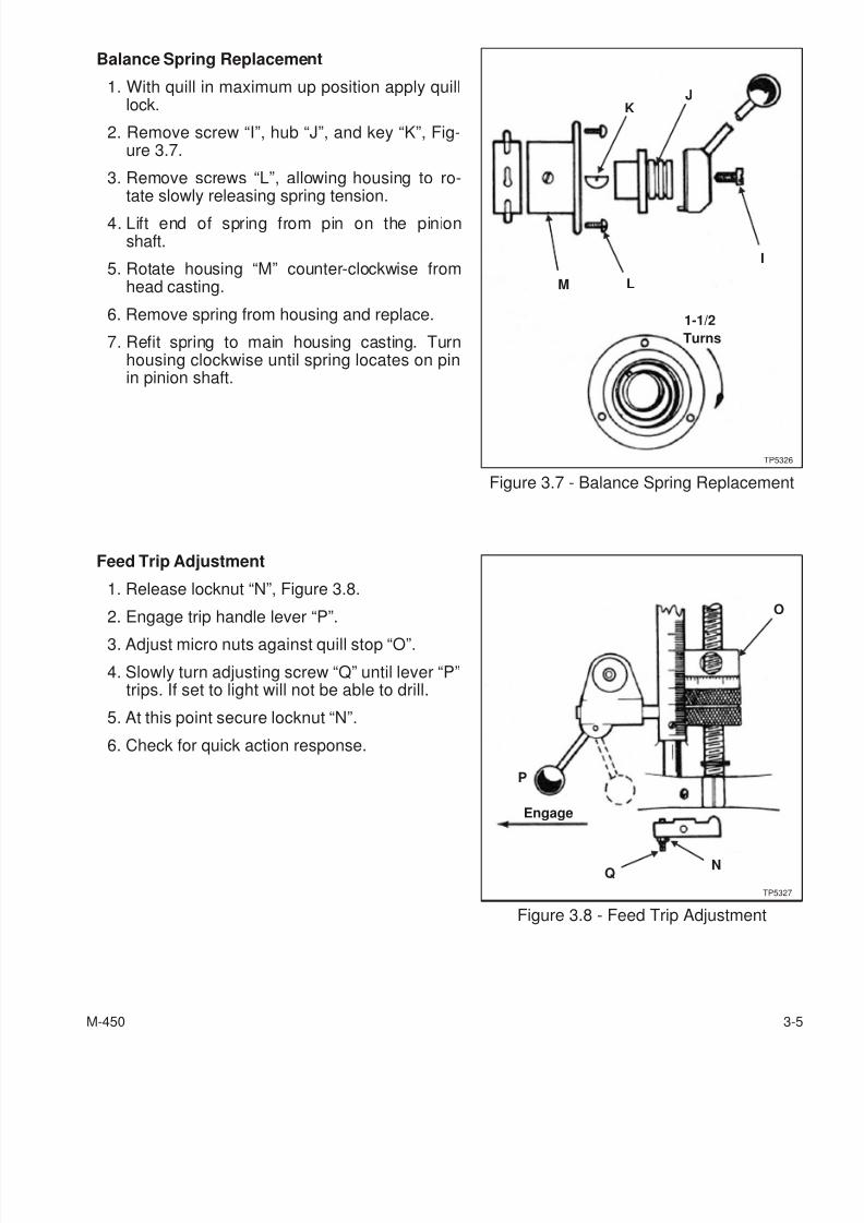
Balance Spring Replacement
1. With quill in maximum up position apply quilllock.
2. Remove screw “I”, hub “J”, and key “K”, Fig-ure 3.7.
3. Remove screws “L”, allowing housing to ro-tate slowly releasing spring tension.
4. Lift end of spring from pin on the pinionshaft.
5. Rotate housing “M” counter-clockwise fromhead casting.
6. Remove spring from housing and replace.
7. Refit spring to main housing casting. Turnhousing clockwise until spring locates on pinin pinion shaft.
Feed Trip Adjustment
1. Release locknut “N”, Figure 3.8.
2. Engage trip handle lever “P”.
3. Adjust micro nuts against quill stop “O”.
4. Slowly turn adjusting screw “Q” until lever “P”trips. If set to light will not be able to drill.
5. At this point secure locknut “N”.
6. Check for quick action response.
M-450 3-5
Figure 3.7 - Balance Spring Replacement
J
I
K
M
TP5326
1-1/2
Turns
L
Figure 3.8 - Feed Trip Adjustment
Engage
O
P
NQ
TP5327
7/28/2019 FullManual Manual Bridgeport
http://slidepdf.com/reader/full/fullmanual-manual-bridgeport 54/134
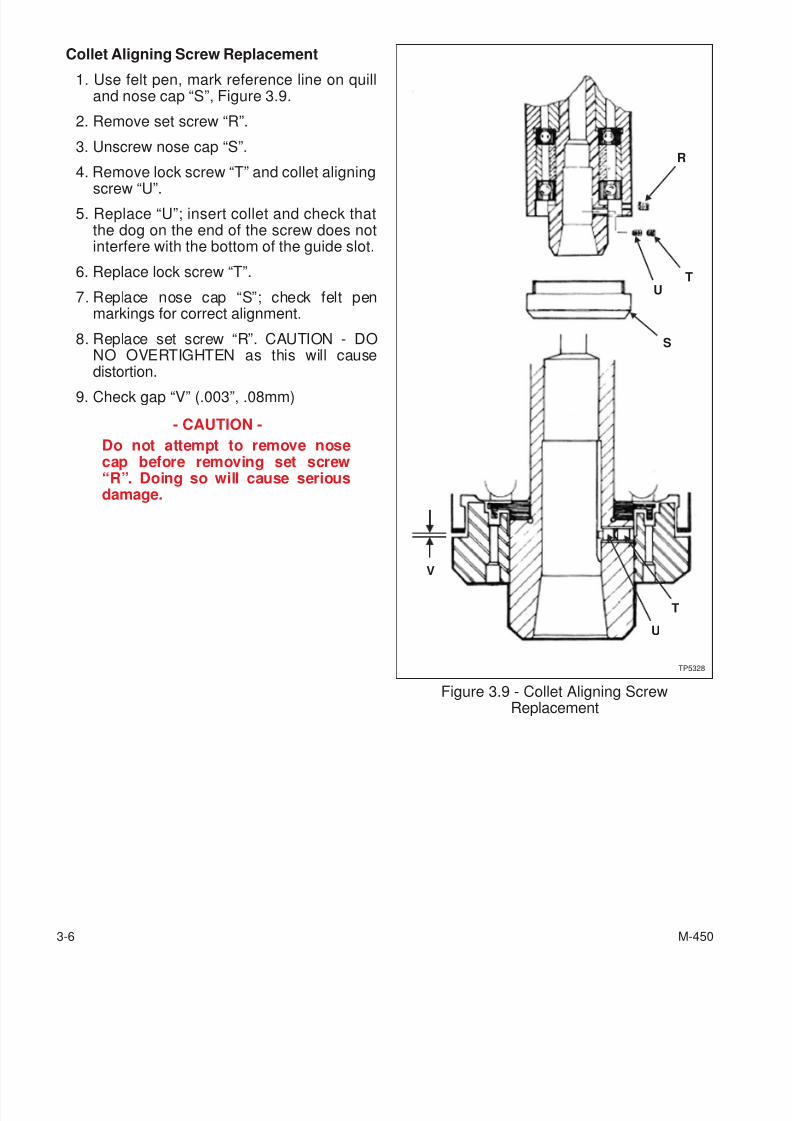
Collet Aligning Screw Replacement
1. Use felt pen, mark reference line on quilland nose cap “S”, Figure 3.9.
2. Remove set screw “R”.
3. Unscrew nose cap “S”.
4. Remove lock screw “T” and collet aligning
screw “U”.5. Replace “U”; insert collet and check that
the dog on the end of the screw does notinterfere with the bottom of the guide slot.
6. Replace lock screw “T”.
7. Replace nose cap “S”; check felt penmarkings for correct alignment.
8. Replace set screw “R”. CAUTION - DONO OVERTIGHTEN as this will causedistortion.
9. Check gap “V” (.003”, .08mm)
- CAUTION -
Do not attempt to remove nosecap before removing set screw“R”. Doing so will cause seriousdamage.
3-6 M-450
Figure 3.9 - Collet Aligning ScrewReplacement
TP5328
UT
R
S
U
T
V
7/28/2019 FullManual Manual Bridgeport
http://slidepdf.com/reader/full/fullmanual-manual-bridgeport 55/134
GIB STRIP ADJUSTMENT
MAINTENANCE PROCEDURES
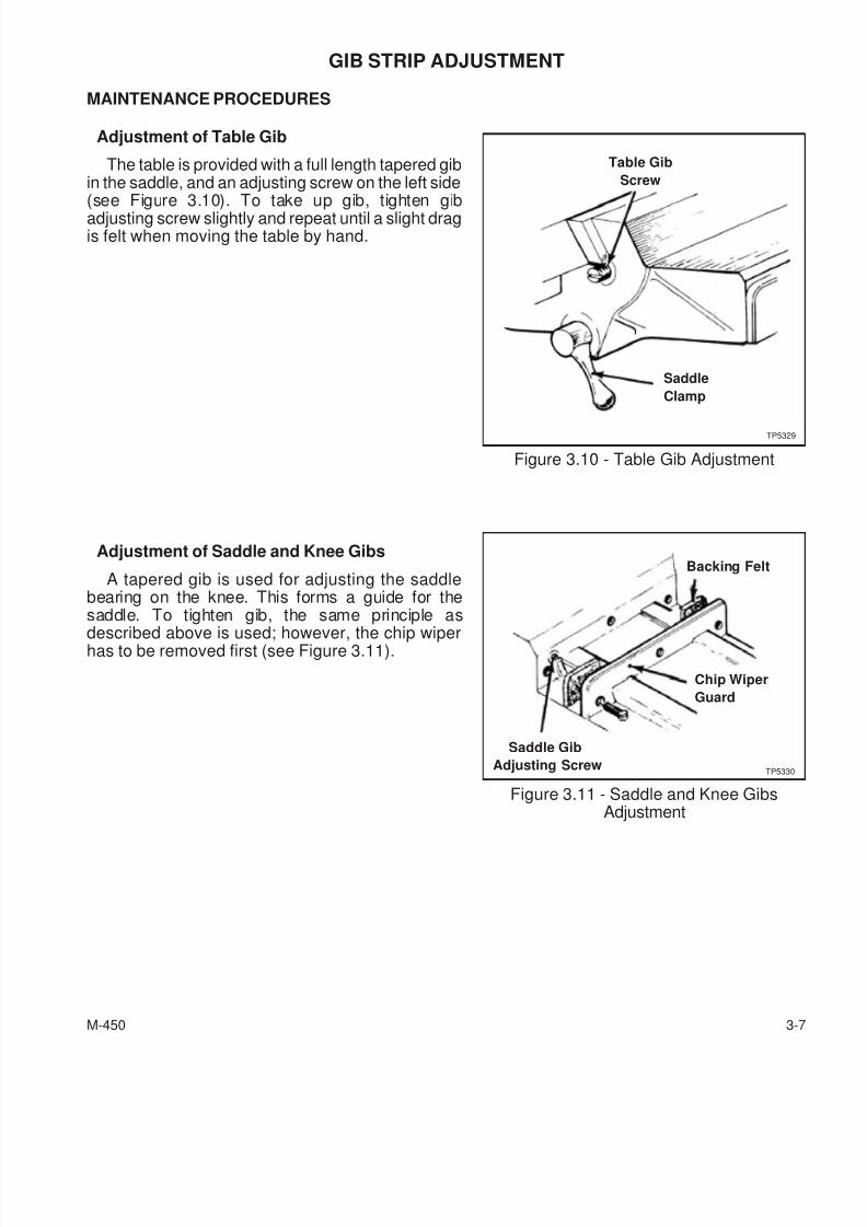
Adjustment of Table Gib
The table is provided with a full length tapered gibin the saddle, and an adjusting screw on the left side(see Figure 3.10). To take up gib, tighten gibadjusting screw slightly and repeat until a slight dragis felt when moving the table by hand.
Adjustment of Saddle and Knee Gibs
A tapered gib is used for adjusting the saddlebearing on the knee. This forms a guide for thesaddle. To tighten gib, the same principle as
described above is used; however, the chip wiperhas to be removed first (see Figure 3.11).
M-450 3-7
Figure 3.10 - Table Gib Adjustment
Table Gib
Screw
Saddle
Clamp
TP5329
Figure 3.11 - Saddle and Knee GibsAdjustment
Saddle Gib
Adjusting ScrewTP5330
Chip Wiper
Guard
Backing Felt
7/28/2019 FullManual Manual Bridgeport
http://slidepdf.com/reader/full/fullmanual-manual-bridgeport 56/134
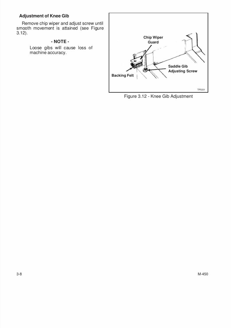
Adjustment of Knee Gib
Remove chip wiper and adjust screw untilsmooth movement is attained (see Figure3.12).
- NOTE -
Loose gibs will cause loss ofmachine accuracy.
3-8 M-450
Figure 3.12 - Knee Gib Adjustment
Saddle Gib
Adjusting Screw
TP5331
Chip Wiper
Guard
Backing Felt
7/28/2019 FullManual Manual Bridgeport
http://slidepdf.com/reader/full/fullmanual-manual-bridgeport 57/134
TABLE SCREW
MAINTENANCE PROCEDURES
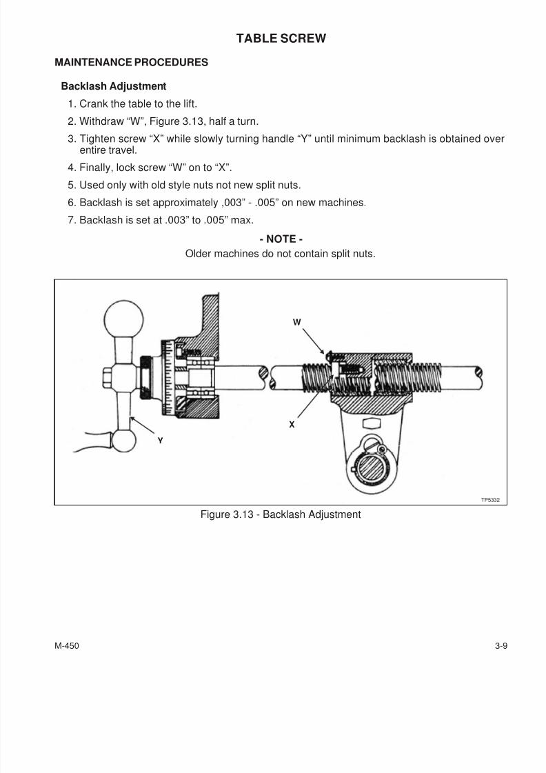
Backlash Adjustment
1. Crank the table to the lift.
2. Withdraw “W”, Figure 3.13, half a turn.
3. Tighten screw “X” while slowly turning handle “Y” until minimum backlash is obtained overentire travel.
4. Finally, lock screw “W” on to “X”.
5. Used only with old style nuts not new split nuts.
6. Backlash is set approximately ,003” - .005” on new machines.
7. Backlash is set at .003” to .005” max.
- NOTE -
Older machines do not contain split nuts.
M-450 3-9
Figure 3.13 - Backlash Adjustment
TP5332
X
W
Y
7/28/2019 FullManual Manual Bridgeport
http://slidepdf.com/reader/full/fullmanual-manual-bridgeport 58/134
CROSS SCREW ASSEMBLY
MAINTENANCE PROCEDURES
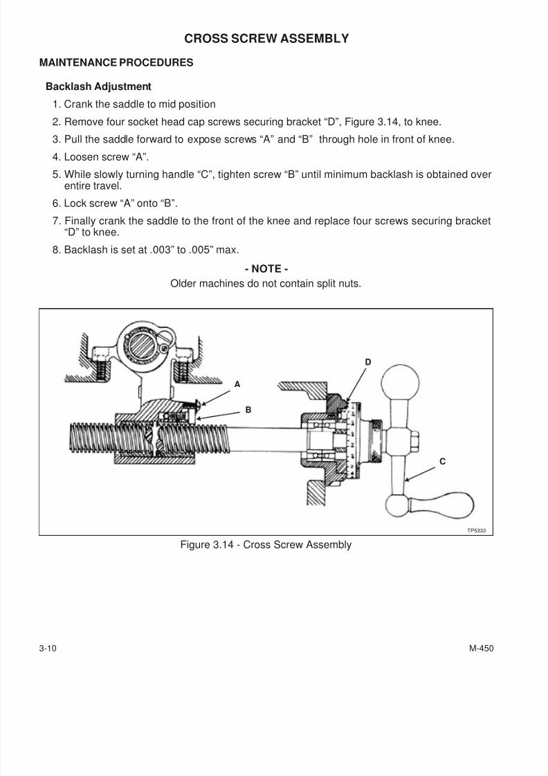
Backlash Adjustment
1. Crank the saddle to mid position
2. Remove four socket head cap screws securing bracket “D”, Figure 3.14, to knee.
3. Pull the saddle forward to expose screws “A” and “B” through hole in front of knee.
4. Loosen screw “A”.
5. While slowly turning handle “C”, tighten screw “B” until minimum backlash is obtained overentire travel.
6. Lock screw “A” onto “B”.
7. Finally crank the saddle to the front of the knee and replace four screws securing bracket“D” to knee.
8. Backlash is set at .003” to .005” max.
- NOTE -
Older machines do not contain split nuts.
3-10 M-450
Figure 3.14 - Cross Screw AssemblyTP5333
D
A
B
C
7/28/2019 FullManual Manual Bridgeport
http://slidepdf.com/reader/full/fullmanual-manual-bridgeport 59/134
E-HEAD
MAINTENANCE PROCEDURES
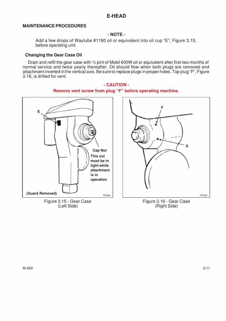
- NOTE -
Add a few drops of Waylube #1180 oil or equivalent into oil cup “E”, Figure 3.15,before operating unit
Changing the Gear Case Oil
Drain and refill the gear case with ½ pint of Mobil 600W oil or equivalent after first two months ofnormal service and twice yearly thereafter. Oil should flow when both plugs are removed andattachment inverted in the vertical axis. Be sure to replace plugs in proper holes. Top plug “F”, Figure3.16, is drilled for vent.
- CAUTION -
Remove vent screw from plug “F” before operating machine.
M-450 3-11
Figure 3.15 - Gear Case(Left Side)
E
Cap Nut
This nut
must be in
tight whileattachment
is in
operation
(Guard Removed)TP5334
Figure 3.16 - Gear Case(Right Side)
TP5335
F
G
7/28/2019 FullManual Manual Bridgeport
http://slidepdf.com/reader/full/fullmanual-manual-bridgeport 60/134
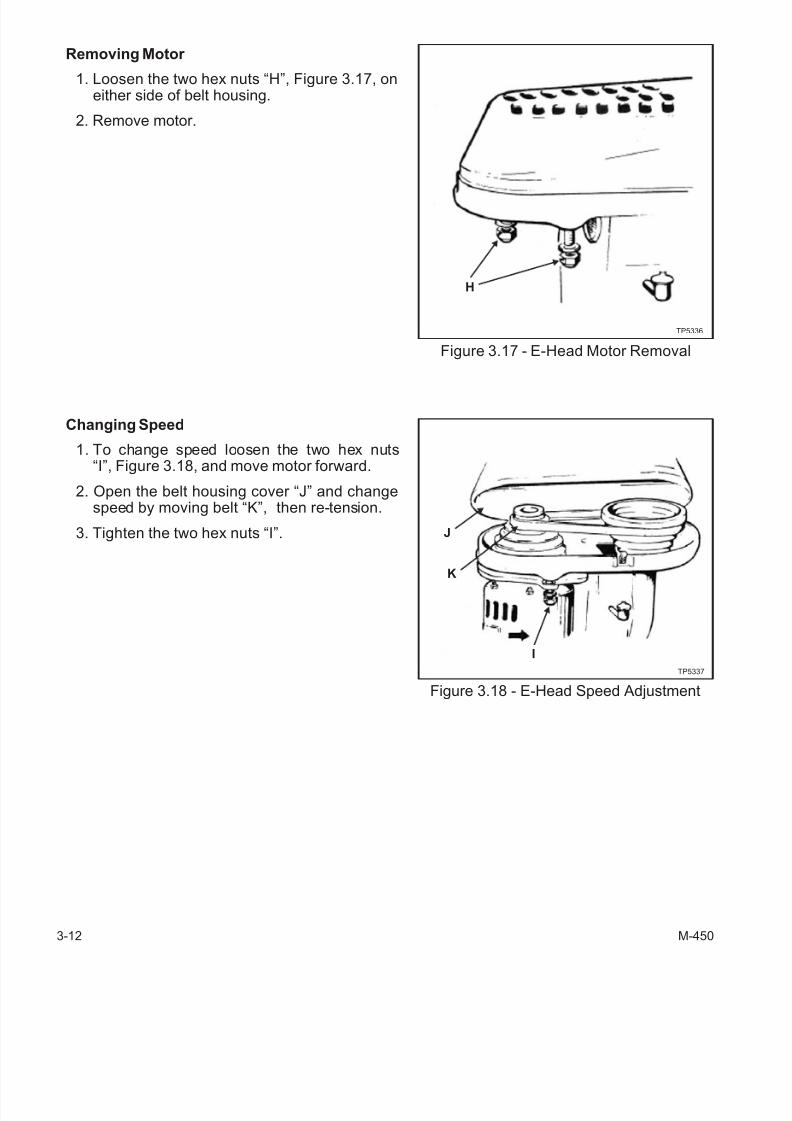
Removing Motor
1. Loosen the two hex nuts “H”, Figure 3.17, oneither side of belt housing.
2. Remove motor.
Changing Speed
1. To change speed loosen the two hex nuts“I”, Figure 3.18, and move motor forward.
2. Open the belt housing cover “J” and changespeed by moving belt “K”, then re-tension.
3. Tighten the two hex nuts “I”.
3-12 M-450
Figure 3.17 - E-Head Motor Removal
Figure 3.18 - E-Head Speed Adjustment
TP5336
J
H
K
I
TP5337
7/28/2019 FullManual Manual Bridgeport
http://slidepdf.com/reader/full/fullmanual-manual-bridgeport 61/134
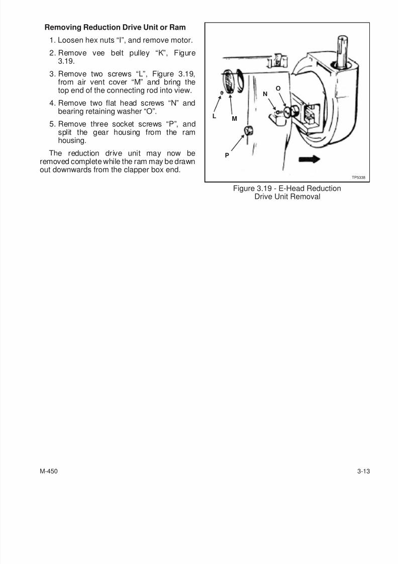
Removing Reduction Drive Unit or Ram
1. Loosen hex nuts “I”, and remove motor.
2. Remove vee belt pulley “K”, Figure3.19.
3. Remove two screws “L”, Figure 3.19,from air vent cover “M” and bring thetop end of the connecting rod into view.
4. Remove two flat head screws “N” andbearing retaining washer “O”.
5. Remove three socket screws “P”, andsplit the gear housing from the ramhousing.
The reduction drive unit may now beremoved complete while the ram may be drawnout downwards from the clapper box end.
M-450 3-13
Figure 3.19 - E-Head ReductionDrive Unit Removal
L
N
M
TP5338
P
O

7/28/2019 FullManual Manual Bridgeport
http://slidepdf.com/reader/full/fullmanual-manual-bridgeport 62/134
- NOTES -
3-14 M-450
7/28/2019 FullManual Manual Bridgeport
http://slidepdf.com/reader/full/fullmanual-manual-bridgeport 63/134
CHAPTER 4 - PARTS LISTINGS
E-HEAD
M-450 4-1
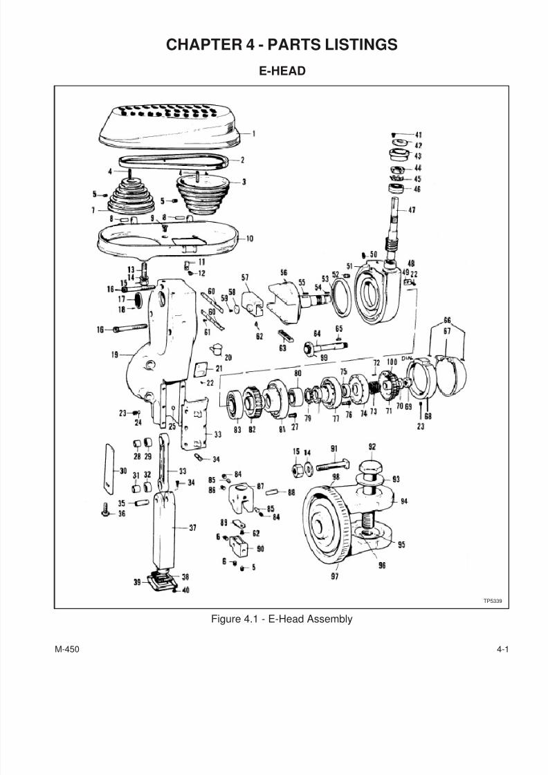
Figure 4.1 - E-Head Assembly
TP5339
7/28/2019 FullManual Manual Bridgeport
http://slidepdf.com/reader/full/fullmanual-manual-bridgeport 64/134
E-HEAD
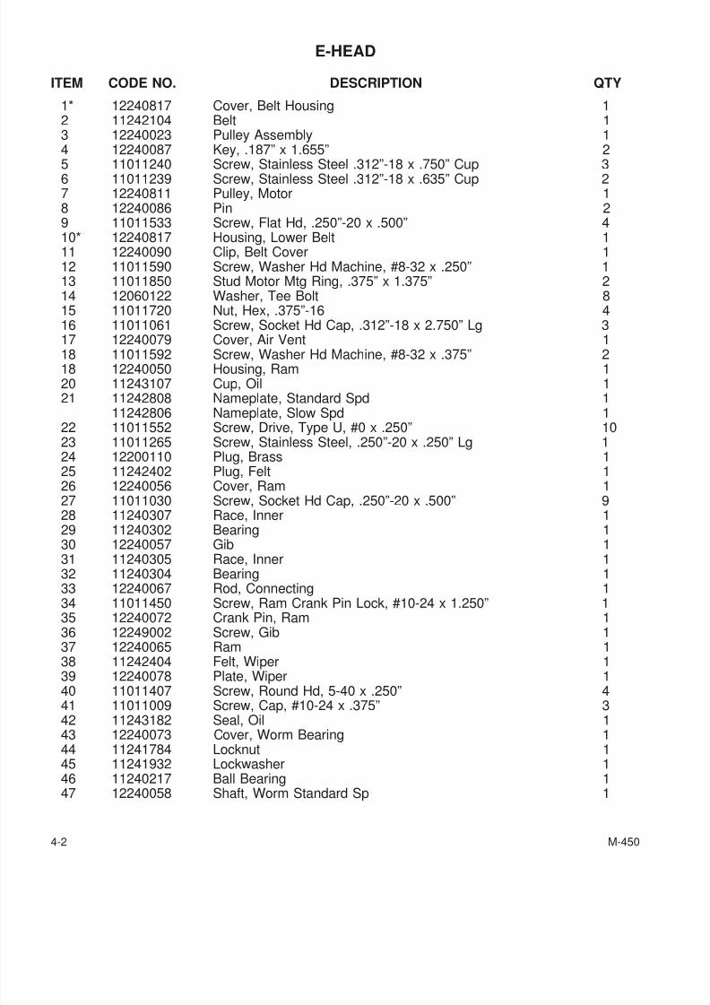
ITEM CODE NO. DESCRIPTION QTY
1* 12240817 Cover, Belt Housing 12 11242104 Belt 13 12240023 Pulley Assembly 14 12240087 Key, .187” x 1.655” 25 11011240 Screw, Stainless Steel .312”-18 x .750” Cup 36 11011239 Screw, Stainless Steel .312”-18 x .635” Cup 27 12240811 Pulley, Motor 18 12240086 Pin 29 11011533 Screw, Flat Hd, .250”-20 x .500” 410* 12240817 Housing, Lower Belt 111 12240090 Clip, Belt Cover 112 11011590 Screw, Washer Hd Machine, #8-32 x .250” 113 11011850 Stud Motor Mtg Ring, .375” x 1.375” 214 12060122 Washer, Tee Bolt 815 11011720 Nut, Hex, .375”-16 416 11011061 Screw, Socket Hd Cap, .312”-18 x 2.750” Lg 3
17 12240079 Cover, Air Vent 118 11011592 Screw, Washer Hd Machine, #8-32 x .375” 218 12240050 Housing, Ram 120 11243107 Cup, Oil 121 11242808 Nameplate, Standard Spd 1
11242806 Nameplate, Slow Spd 122 11011552 Screw, Drive, Type U, #0 x .250” 1023 11011265 Screw, Stainless Steel, .250”-20 x .250” Lg 124 12200110 Plug, Brass 125 11242402 Plug, Felt 126 12240056 Cover, Ram 127 11011030 Screw, Socket Hd Cap, .250”-20 x .500” 9
28 11240307 Race, Inner 129 11240302 Bearing 130 12240057 Gib 131 11240305 Race, Inner 132 11240304 Bearing 133 12240067 Rod, Connecting 134 11011450 Screw, Ram Crank Pin Lock, #10-24 x 1.250” 135 12240072 Crank Pin, Ram 136 12249002 Screw, Gib 137 12240065 Ram 138 11242404 Felt, Wiper 139 12240078 Plate, Wiper 1
40 11011407 Screw, Round Hd, 5-40 x .250” 441 11011009 Screw, Cap, #10-24 x .375” 342 11243182 Seal, Oil 143 12240073 Cover, Worm Bearing 144 11241784 Locknut 145 11241932 Lockwasher 146 11240217 Ball Bearing 147 12240058 Shaft, Worm Standard Sp 1
4-2 M-450
7/28/2019 FullManual Manual Bridgeport
http://slidepdf.com/reader/full/fullmanual-manual-bridgeport 65/134
ITEM CODE NO. DESCRIPTION QTY
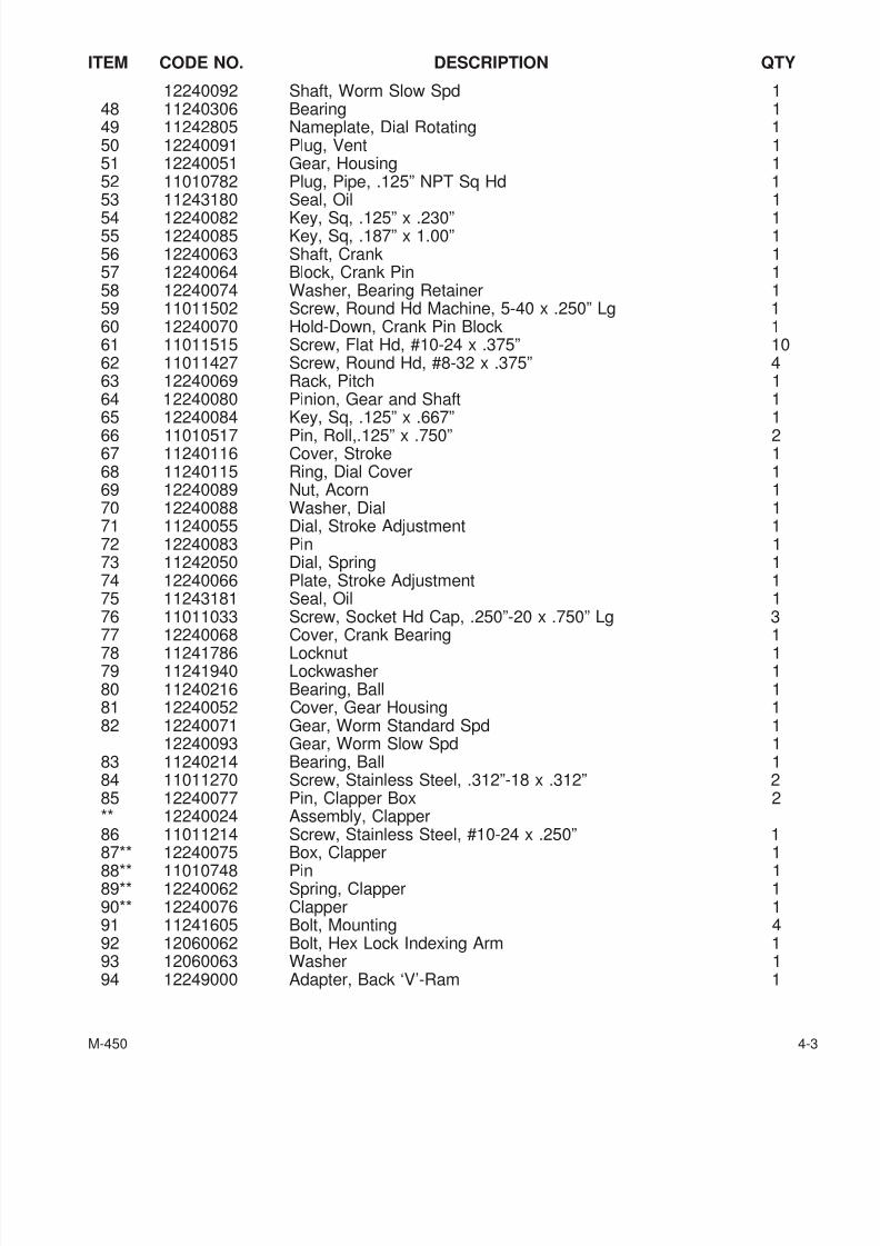
12240092 Shaft, Worm Slow Spd 148 11240306 Bearing 149 11242805 Nameplate, Dial Rotating 150 12240091 Plug, Vent 151 12240051 Gear, Housing 152 11010782 Plug, Pipe, .125” NPT Sq Hd 153 11243180 Seal, Oil 1
54 12240082 Key, Sq, .125” x .230” 155 12240085 Key, Sq, .187” x 1.00” 156 12240063 Shaft, Crank 157 12240064 Block, Crank Pin 158 12240074 Washer, Bearing Retainer 159 11011502 Screw, Round Hd Machine, 5-40 x .250” Lg 160 12240070 Hold-Down, Crank Pin Block 161 11011515 Screw, Flat Hd, #10-24 x .375” 1062 11011427 Screw, Round Hd, #8-32 x .375” 463 12240069 Rack, Pitch 164 12240080 Pinion, Gear and Shaft 165 12240084 Key, Sq, .125” x .667” 166 11010517 Pin, Roll,.125” x .750” 267 11240116 Cover, Stroke 168 11240115 Ring, Dial Cover 169 12240089 Nut, Acorn 170 12240088 Washer, Dial 171 11240055 Dial, Stroke Adjustment 172 12240083 Pin 173 11242050 Dial, Spring 174 12240066 Plate, Stroke Adjustment 175 11243181 Seal, Oil 176 11011033 Screw, Socket Hd Cap, .250”-20 x .750” Lg 3
77 12240068 Cover, Crank Bearing 178 11241786 Locknut 179 11241940 Lockwasher 180 11240216 Bearing, Ball 181 12240052 Cover, Gear Housing 182 12240071 Gear, Worm Standard Spd 1
12240093 Gear, Worm Slow Spd 183 11240214 Bearing, Ball 184 11011270 Screw, Stainless Steel, .312”-18 x .312” 285 12240077 Pin, Clapper Box 2** 12240024 Assembly, Clapper86 11011214 Screw, Stainless Steel, #10-24 x .250” 1
87** 12240075 Box, Clapper 188** 11010748 Pin 189** 12240062 Spring, Clapper 190** 12240076 Clapper 191 11241605 Bolt, Mounting 492 12060062 Bolt, Hex Lock Indexing Arm 193 12060063 Washer 194 12249000 Adapter, Back ‘V’-Ram 1
M-450 4-3

7/28/2019 FullManual Manual Bridgeport
http://slidepdf.com/reader/full/fullmanual-manual-bridgeport 66/134
ITEM CODE NO. DESCRIPTION QTY
95 12060064 Locknut, Adapter 196 11010713 Pin, Dowel, .187” x .500” 197 11060603 Scale, Ram Adapter 198 11980426 Screw, Drive, Type U, #4 x .312” 299 12240081 Collar 1100 11242804 Nameplate, Stroke Adj - Inch 1
11242810 nameplate, Stroke Adj - Metric 1
11011552 Screw, Drive, Type U, #0 x .250” 212240135 Assembly, Motor (Not Shown) 1
*Items 1 and 10 sold as assembly only.
**Items 87, 88, 89 and 90 sold as assembly only.
4-4 M-450
7/28/2019 FullManual Manual Bridgeport
http://slidepdf.com/reader/full/fullmanual-manual-bridgeport 67/134
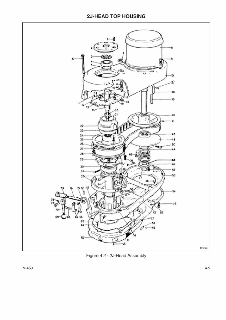
2J-HEAD TOP HOUSING
M-450 4-5
Figure 4.2 - 2J-Head Assembly
TP5340
7/28/2019 FullManual Manual Bridgeport
http://slidepdf.com/reader/full/fullmanual-manual-bridgeport 68/134
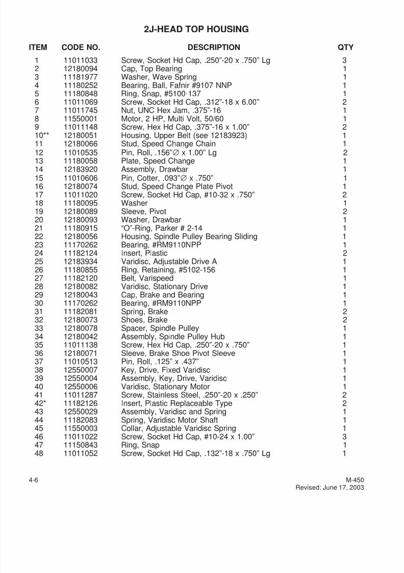
2J-HEAD TOP HOUSING
ITEM CODE NO. DESCRIPTION QTY
1 11011033 Screw, Socket Hd Cap, .250”-20 x .750” Lg 32 12180094 Cap, Top Bearing 13 11181977 Washer, Wave Spring 14 11180252 Bearing, Ball, Fafnir #9107 NNP 15 11180848 Ring, Snap, #5100-137 16 11011069 Screw, Socket Hd Cap, .312”-18 x 6.00” 27 11011745 Nut, UNC Hex Jam, .375”-16 18 11550001 Motor, 2 HP, Multi Volt, 50/60 19 11011148 Screw, Hex Hd Cap, .375”-16 x 1.00” 210** 12180051 Housing, Upper Belt (see 12183923) 111 12180066 Stud, Speed Change Chain 112 11010535 Pin, Roll, .156”∅ x 1.00” Lg 213 11180058 Plate, Speed Change 114 12183920 Assembly, Drawbar 115 11010606 Pin, Cotter, .093”∅ x .750” 116 12180074 Stud, Speed Change Plate Pivot 1
17 11011020 Screw, Socket Hd Cap, #10-32 x .750” 218 11180095 Washer 119 12180089 Sleeve, Pivot 220 12180093 Washer, Drawbar 121 11180915 “O”-Ring, Parker # 2-14 122 12180056 Housing, Spindle Pulley Bearing Sliding 123 11170262 Bearing, #RM9110NPP 124 11182124 Insert, Plastic 225 12183934 Varidisc, Adjustable Drive A 126 11180855 Ring, Retaining, #5102-156 127 11182120 Belt, Varispeed 128 12180082 Varidisc, Stationary Drive 1
29 12180043 Cap, Brake and Bearing 130 11170262 Bearing, #RM9110NPP 131 11182081 Spring, Brake 232 12180073 Shoes, Brake 233 12180078 Spacer, Spindle Pulley 134 12180042 Assembly, Spindle Pulley Hub 135 11011138 Screw, Hex Hd Cap, .250”-20 x .750” 136 12180071 Sleeve, Brake Shoe Pivot Sleeve 137 11010513 Pin, Roll, .125” x .437” 138 12550007 Key, Drive, Fixed Varidisc 139 12550004 Assembly, Key, Drive, Varidisc 140 12550006 Varidisc, Stationary Motor 1
41 11011287 Screw, Stainless Steel, .250”-20 x .250” 242* 11182126 Insert, Plastic Replaceable Type 243 12550029 Assembly, Varidisc and Spring 144 11182083 Spring, Varidisc Motor Shaft 145 11550003 Collar, Adjustable Varidisc Spring 146 11011022 Screw, Socket Hd Cap, #10-24 x 1.00” 347 11150843 Ring, Snap 148 11011052 Screw, Socket Hd Cap, .132”-18 x .750” Lg 1
4-6 M-450Revised: June 17, 2003
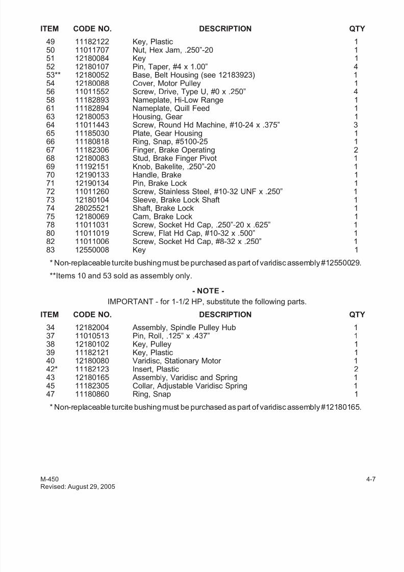
7/28/2019 FullManual Manual Bridgeport
http://slidepdf.com/reader/full/fullmanual-manual-bridgeport 69/134
ITEM CODE NO. DESCRIPTION QTY
49 11182122 Key, Plastic 150 11011707 Nut, Hex Jam, .250”-20 151 12180084 Key 152 12180107 Pin, Taper, #4 x 1.00” 453** 12180052 Base, Belt Housing (see 12183923) 154 12180088 Cover, Motor Pulley 156 11011552 Screw, Drive, Type U, #0 x .250” 4
58 11182893 Nameplate, Hi-Low Range 161 11182894 Nameplate, Quill Feed 163 12180053 Housing, Gear 164 11011443 Screw, Round Hd Machine, #10-24 x .375” 365 11185030 Plate, Gear Housing 166 11180818 Ring, Snap, #5100-25 167 11182306 Finger, Brake Operating 268 12180083 Stud, Brake Finger Pivot 169 11192151 Knob, Bakelite, .250”-20 170 12190133 Handle, Brake 171 12190134 Pin, Brake Lock 172 11011260 Screw, Stainless Steel, #10-32 UNF x .250” 173 12180104 Sleeve, Brake Lock Shaft 174 28025521 Shaft, Brake Lock 175 12180069 Cam, Brake Lock 178 11011031 Screw, Socket Hd Cap, .250”-20 x .625” 180 11011019 Screw, Flat Hd Cap, #10-32 x .500” 182 11011006 Screw, Socket Hd Cap, #8-32 x .250” 183 12550008 Key 1
* Non-replaceable turcite bushing must be purchased as part of varidisc assembly #12550029.
**Items 10 and 53 sold as assembly only.
- NOTE -
IMPORTANT - for 1-1/2 HP, substitute the following parts.
ITEM CODE NO. DESCRIPTION QTY
34 12182004 Assembly, Spindle Pulley Hub 137 11010513 Pin, Roll, .125” x .437” 138 12180102 Key, Pulley 139 11182121 Key, Plastic 140 12180080 Varidisc, Stationary Motor 142* 11182123 Insert, Plastic 243 12180165 Assembly, Varidisc and Spring 145 11182305 Collar, Adjustable Varidisc Spring 1
47 11180860 Ring, Snap 1
* Non-replaceable turcite bushing must be purchased as part of varidisc assembly #12180165.
M-450 4-7Revised: August 29, 2005
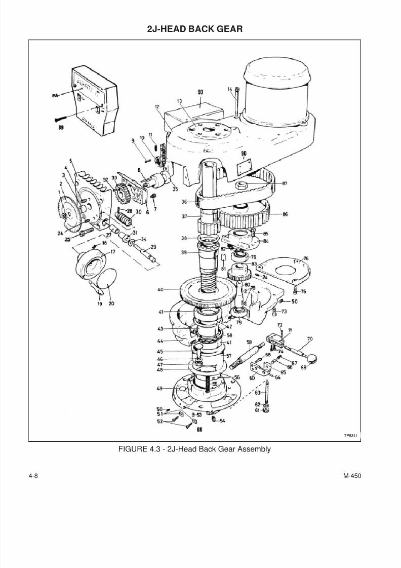
7/28/2019 FullManual Manual Bridgeport
http://slidepdf.com/reader/full/fullmanual-manual-bridgeport 70/134
2J-HEAD BACK GEAR
4-8 M-450
FIGURE 4.3 - 2J-Head Back Gear Assembly
TP5341
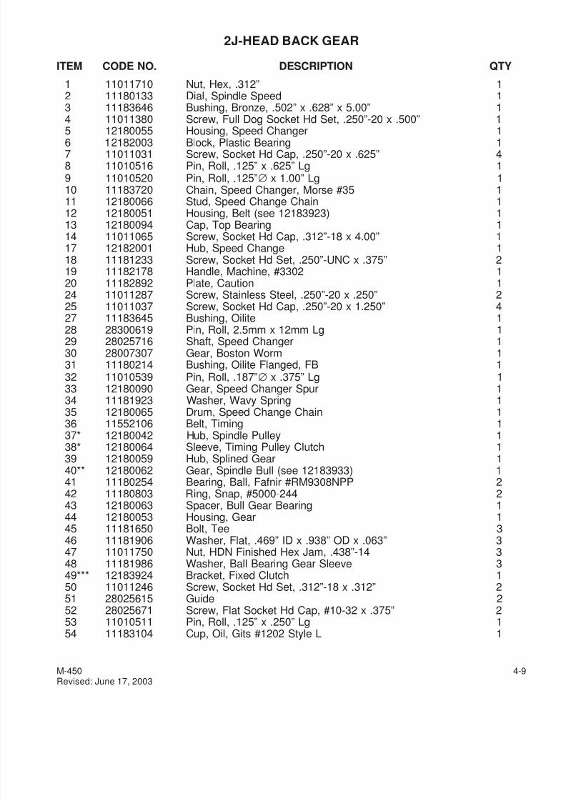
7/28/2019 FullManual Manual Bridgeport
http://slidepdf.com/reader/full/fullmanual-manual-bridgeport 71/134
2J-HEAD BACK GEAR
ITEM CODE NO. DESCRIPTION QTY
1 11011710 Nut, Hex, .312” 12 11180133 Dial, Spindle Speed 13 11183646 Bushing, Bronze, .502” x .628” x 5.00” 14 11011380 Screw, Full Dog Socket Hd Set, .250”-20 x .500” 15 12180055 Housing, Speed Changer 16 12182003 Block, Plastic Bearing 17 11011031 Screw, Socket Hd Cap, .250”-20 x .625” 48 11010516 Pin, Roll, .125” x .625” Lg 19 11010520 Pin, Roll, .125”∅ x 1.00” Lg 110 11183720 Chain, Speed Changer, Morse #35 111 12180066 Stud, Speed Change Chain 112 12180051 Housing, Belt (see 12183923) 113 12180094 Cap, Top Bearing 114 11011065 Screw, Socket Hd Cap, .312”-18 x 4.00” 117 12182001 Hub, Speed Change 118 11181233 Screw, Socket Hd Set, .250”-UNC x .375” 2
19 11182178 Handle, Machine, #3302 120 11182892 Plate, Caution 124 11011287 Screw, Stainless Steel, .250”-20 x .250” 225 11011037 Screw, Socket Hd Cap, .250”-20 x 1.250” 427 11183645 Bushing, Oilite 128 28300619 Pin, Roll, 2.5mm x 12mm Lg 129 28025716 Shaft, Speed Changer 130 28007307 Gear, Boston Worm 131 11180214 Bushing, Oilite Flanged, FB 132 11010539 Pin, Roll, .187”∅ x .375” Lg 133 12180090 Gear, Speed Changer Spur 134 11181923 Washer, Wavy Spring 1
35 12180065 Drum, Speed Change Chain 136 11552106 Belt, Timing 137* 12180042 Hub, Spindle Pulley 138* 12180064 Sleeve, Timing Pulley Clutch 139 12180059 Hub, Splined Gear 140** 12180062 Gear, Spindle Bull (see 12183933) 141 11180254 Bearing, Ball, Fafnir #RM9308NPP 242 11180803 Ring, Snap, #5000-244 243 12180063 Spacer, Bull Gear Bearing 144 12180053 Housing, Gear 145 11181650 Bolt, Tee 346 11181906 Washer, Flat, .469” ID x .938” OD x .063” 3
47 11011750 Nut, HDN Finished Hex Jam, .438”-14 348 11181986 Washer, Ball Bearing Gear Sleeve 349*** 12183924 Bracket, Fixed Clutch 150 11011246 Screw, Socket Hd Set, .312”-18 x .312” 251 28025615 Guide 252 28025671 Screw, Flat Socket Hd Cap, #10-32 x .375” 253 11010511 Pin, Roll, .125” x .250” Lg 154 11183104 Cup, Oil, Gits #1202 Style L 1
M-450 4-9Revised: June 17, 2003
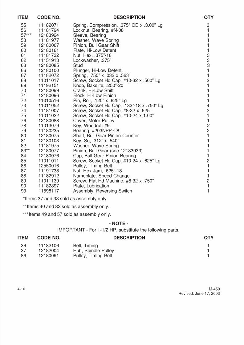
7/28/2019 FullManual Manual Bridgeport
http://slidepdf.com/reader/full/fullmanual-manual-bridgeport 72/134
ITEM CODE NO. DESCRIPTION QTY
55 11182071 Spring, Compression, .375” OD x .3.00” Lg 356 11181794 Locknut, Bearing, #N-08 157*** 12183924 Sleeve, Bearing 158 11181977 Washer, Wave Spring 159 12180067 Pinion, Bull Gear Shift 160 12180161 Plate, Hi-Low Detent 161 11181732 Nut, Hex, .375”-16 3
62 11151913 Lockwasher, .375” 363 12180085 Stud 366 12180100 Plunger, Hi-Low Detent 167 11182072 Spring, .750” x .032 x .563” 168 11011017 Screw, Socket Hd Cap, #10-32 x .500” Lg 269 11192151 Knob, Bakelite, .250”-20 170 12180099 Crank, Hi-Low Shift 171 12180096 Block, Hi-Low Pinion 172 11010516 Pin, Roll, .125” x .625” Lg 173 11011052 Screw, Socket Hd Cap, .132”-18 x .750” Lg 474 11181007 Screw, Socket Hd Cap, #8-32 x .625” 275 11011022 Screw, Socket Hd Cap, #10-24 x 1.00” 176 12180088 Cover, Motor Pulley 178 11013079 Key, Woodruff #9 279 11180235 Bearing, #203NPP-C8 280 12180075 Shaft, Bull Gear Pinion Counter 181 12180103 Key, Sq, .312” x .540” 182 11181975 Washer, Wave Spring 183** 12180077 Pinion, Bull Gear (see 12183933) 184 12180076 Cap, Bull Gear Pinion Bearing 185 11011011 Screw, Socket Hd Cap, #10-24 x .625” Lg 286 12550016 Pulley, Timing Belt 187 11191738 Nut, Hex Jam, .625”-18 1
88 11182912 Nameplate, Speed Change 189 11011139 Screw, Flat Hd Machine, #8-32 x .750” 290 11182897 Plate, Lubrication 193 11598117 Assembly, Reversing Switch 1
*Items 37 and 38 sold as assembly only.
**Items 40 and 83 sold as assembly only.
***Items 49 and 57 sold as assembly only.
- NOTE -
IMPORTANT - For 1-1/2 HP, substitute the following parts.
ITEM CODE NO. DESCRIPTION QTY
36 11182106 Belt, Timing 137 12182004 Hub, Spindle Pulley 186 12180091 Pulley, Timing Belt 1
4-10 M-450Revised: June 17, 2003
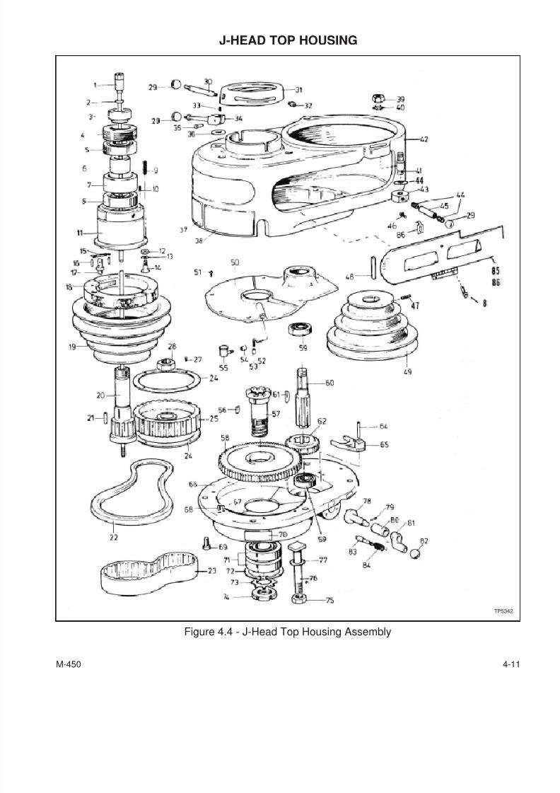
7/28/2019 FullManual Manual Bridgeport
http://slidepdf.com/reader/full/fullmanual-manual-bridgeport 73/134
J-HEAD TOP HOUSING
M-450 4-11
Figure 4.4 - J-Head Top Housing Assembly
TP5342
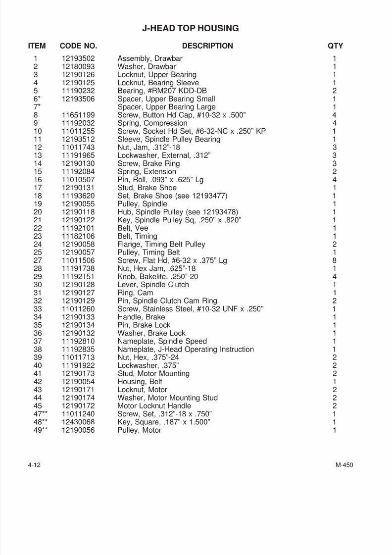
7/28/2019 FullManual Manual Bridgeport
http://slidepdf.com/reader/full/fullmanual-manual-bridgeport 74/134
J-HEAD TOP HOUSING
ITEM CODE NO. DESCRIPTION QTY
1 12193502 Assembly, Drawbar 12 12180093 Washer, Drawbar 13 12190126 Locknut, Upper Bearing 14 12190125 Locknut, Bearing Sleeve 15 11190232 Bearing, #RM207 KDD-DB 26* 12193506 Spacer, Upper Bearing Small 17* Spacer, Upper Bearing Large 18 11651199 Screw, Button Hd Cap, #10-32 x .500” 49 11192032 Spring, Compression 410 11011255 Screw, Socket Hd Set, #6-32-NC x .250” KP 111 12193512 Sleeve, Spindle Pulley Bearing 112 11011743 Nut, Jam, .312”-18 313 11191965 Lockwasher, External, .312” 314 12190130 Screw, Brake Ring 315 11192084 Spring, Extension 216 11010507 Pin, Roll, .093” x .625” Lg 4
17 12190131 Stud, Brake Shoe 118 11193620 Set, Brake Shoe (see 12193477) 119 12190055 Pulley, Spindle 120 12190118 Hub, Spindle Pulley (see 12193478) 121 12190122 Key, Spindle Pulley Sq, .250” x .820” 122 11192101 Belt, Vee 123 11182106 Belt, Timing 124 12190058 Flange, Timing Belt Pulley 225 12190057 Pulley, Timing Belt 127 11011506 Screw, Flat Hd, #6-32 x .375” Lg 828 11191738 Nut, Hex Jam, .625”-18 129 11192151 Knob, Bakelite, .250”-20 4
30 12190128 Lever, Spindle Clutch 131 12190127 Ring, Cam 132 12190129 Pin, Spindle Clutch Cam Ring 233 11011260 Screw, Stainless Steel, #10-32 UNF x .250” 134 12190133 Handle, Brake 135 12190134 Pin, Brake Lock 136 12190132 Washer, Brake Lock 137 11192810 Nameplate, Spindle Speed 138 11192835 Nameplate, J-Head Operating Instruction 139 11011713 Nut, Hex, .375”-24 240 11191922 Lockwasher, .375” 241 12190173 Stud, Motor Mounting 2
42 12190054 Housing, Belt 143 12190171 Locknut, Motor 244 12190174 Washer, Motor Mounting Stud 245 12190172 Motor Locknut Handle 247** 11011240 Screw, Set, .312”-18 x .750” 148** 12430068 Key, Square, .187” x 1.500” 149** 12190056 Pulley, Motor 1
4-12 M-450
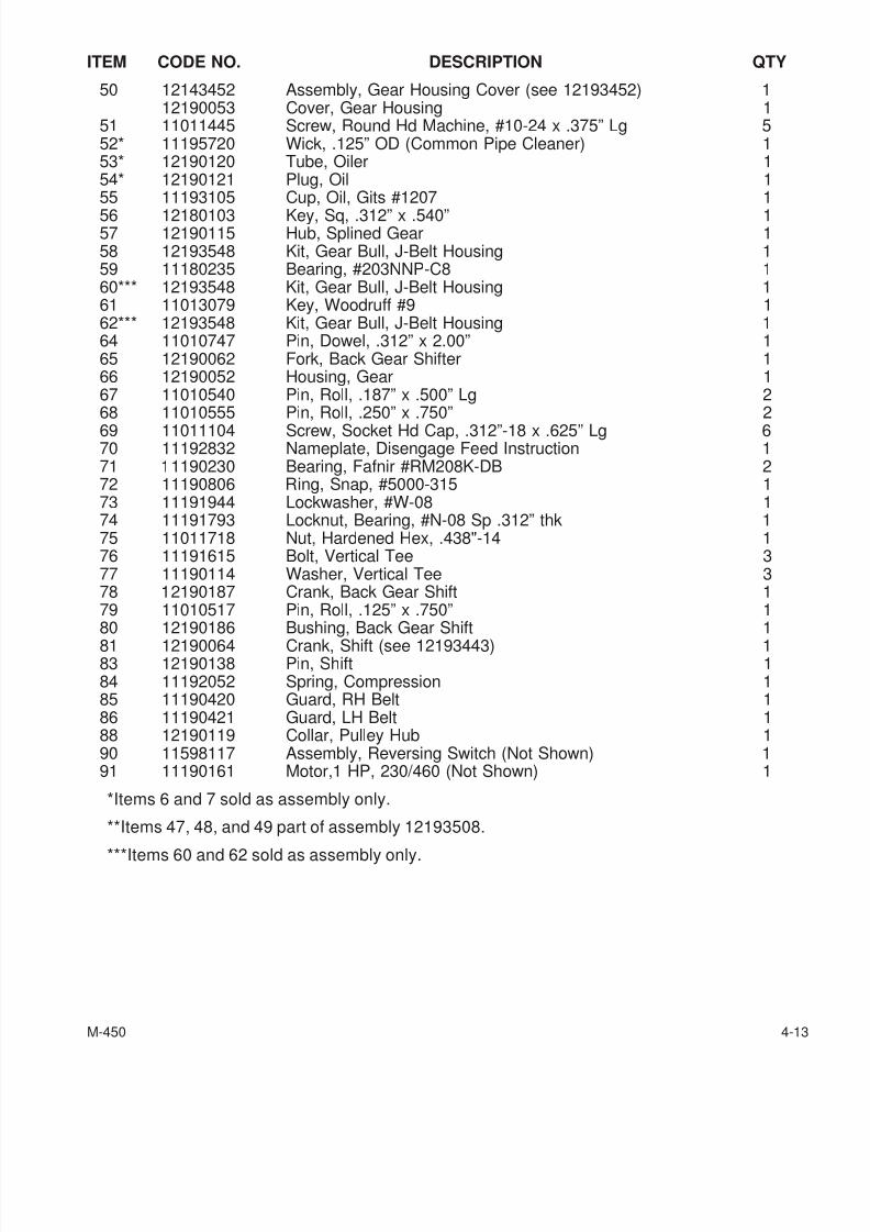
7/28/2019 FullManual Manual Bridgeport
http://slidepdf.com/reader/full/fullmanual-manual-bridgeport 75/134
ITEM CODE NO. DESCRIPTION QTY
50 12143452 Assembly, Gear Housing Cover (see 12193452) 112190053 Cover, Gear Housing 1
51 11011445 Screw, Round Hd Machine, #10-24 x .375” Lg 552* 11195720 Wick, .125” OD (Common Pipe Cleaner) 153* 12190120 Tube, Oiler 154* 12190121 Plug, Oil 155 11193105 Cup, Oil, Gits #1207 1
56 12180103 Key, Sq, .312” x .540” 157 12190115 Hub, Splined Gear 158 12193548 Kit, Gear Bull, J-Belt Housing 159 11180235 Bearing, #203NNP-C8 160*** 12193548 Kit, Gear Bull, J-Belt Housing 161 11013079 Key, Woodruff #9 162*** 12193548 Kit, Gear Bull, J-Belt Housing 164 11010747 Pin, Dowel, .312” x 2.00” 165 12190062 Fork, Back Gear Shifter 166 12190052 Housing, Gear 167 11010540 Pin, Roll, .187” x .500” Lg 268 11010555 Pin, Roll, .250” x .750” 269 11011104 Screw, Socket Hd Cap, .312”-18 x .625” Lg 670 11192832 Nameplate, Disengage Feed Instruction 171 11190230 Bearing, Fafnir #RM208K-DB 272 11190806 Ring, Snap, #5000-315 173 11191944 Lockwasher, #W-08 174 11191793 Locknut, Bearing, #N-08 Sp .312” thk 175 11011718 Nut, Hardened Hex, .438"-14 176 11191615 Bolt, Vertical Tee 377 11190114 Washer, Vertical Tee 378 12190187 Crank, Back Gear Shift 179 11010517 Pin, Roll, .125” x .750” 1
80 12190186 Bushing, Back Gear Shift 181 12190064 Crank, Shift (see 12193443) 183 12190138 Pin, Shift 184 11192052 Spring, Compression 185 11190420 Guard, RH Belt 186 11190421 Guard, LH Belt 188 12190119 Collar, Pulley Hub 190 11598117 Assembly, Reversing Switch (Not Shown) 191 11190161 Motor,1 HP, 230/460 (Not Shown) 1
*Items 6 and 7 sold as assembly only.
**Items 47, 48, and 49 part of assembly 12193508.
***Items 60 and 62 sold as assembly only.
M-450 4-13
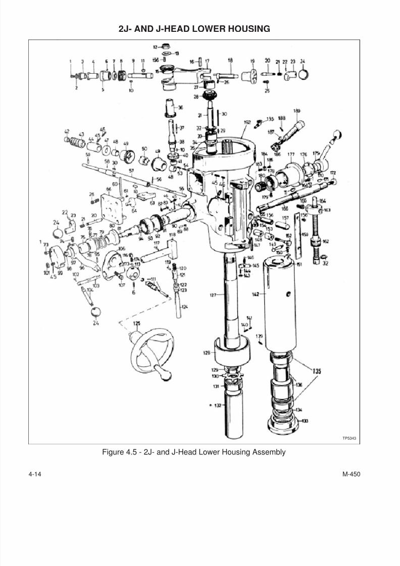
7/28/2019 FullManual Manual Bridgeport
http://slidepdf.com/reader/full/fullmanual-manual-bridgeport 76/134
2J- AND J-HEAD LOWER HOUSING
4-14 M-450
Figure 4.5 - 2J- and J-Head Lower Housing Assembly
TP5343
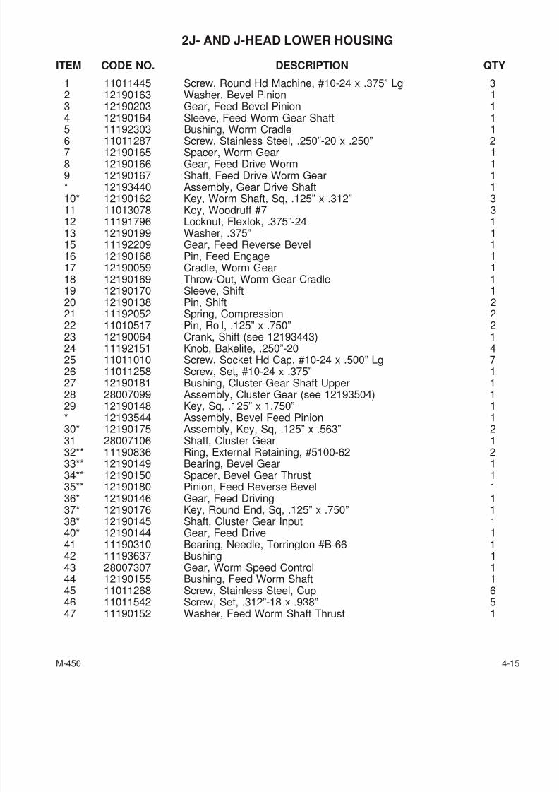
7/28/2019 FullManual Manual Bridgeport
http://slidepdf.com/reader/full/fullmanual-manual-bridgeport 77/134
2J- AND J-HEAD LOWER HOUSING
ITEM CODE NO. DESCRIPTION QTY
1 11011445 Screw, Round Hd Machine, #10-24 x .375” Lg 32 12190163 Washer, Bevel Pinion 13 12190203 Gear, Feed Bevel Pinion 14 12190164 Sleeve, Feed Worm Gear Shaft 15 11192303 Bushing, Worm Cradle 16 11011287 Screw, Stainless Steel, .250”-20 x .250” 27 12190165 Spacer, Worm Gear 18 12190166 Gear, Feed Drive Worm 19 12190167 Shaft, Feed Drive Worm Gear 1* 12193440 Assembly, Gear Drive Shaft 110* 12190162 Key, Worm Shaft, Sq, .125” x .312” 311 11013078 Key, Woodruff #7 312 11191796 Locknut, Flexlok, .375”-24 113 12190199 Washer, .375” 115 11192209 Gear, Feed Reverse Bevel 116 12190168 Pin, Feed Engage 1
17 12190059 Cradle, Worm Gear 118 12190169 Throw-Out, Worm Gear Cradle 119 12190170 Sleeve, Shift 120 12190138 Pin, Shift 221 11192052 Spring, Compression 222 11010517 Pin, Roll, .125” x .750” 223 12190064 Crank, Shift (see 12193443) 124 11192151 Knob, Bakelite, .250”-20 425 11011010 Screw, Socket Hd Cap, #10-24 x .500” Lg 726 11011258 Screw, Set, #10-24 x .375” 127 12190181 Bushing, Cluster Gear Shaft Upper 128 28007099 Assembly, Cluster Gear (see 12193504) 1
29 12190148 Key, Sq, .125” x 1.750” 1* 12193544 Assembly, Bevel Feed Pinion 130* 12190175 Assembly, Key, Sq, .125” x .563” 231 28007106 Shaft, Cluster Gear 132** 11190836 Ring, External Retaining, #5100-62 233** 12190149 Bearing, Bevel Gear 134** 12190150 Spacer, Bevel Gear Thrust 135** 12190180 Pinion, Feed Reverse Bevel 136* 12190146 Gear, Feed Driving 137* 12190176 Key, Round End, Sq, .125” x .750” 138* 12190145 Shaft, Cluster Gear Input 140* 12190144 Gear, Feed Drive 1
41 11190310 Bearing, Needle, Torrington #B-66 142 11193637 Bushing 143 28007307 Gear, Worm Speed Control 144 12190155 Bushing, Feed Worm Shaft 145 11011268 Screw, Stainless Steel, Cup 646 11011542 Screw, Set, .312”-18 x .938” 547 11190152 Washer, Feed Worm Shaft Thrust 1
M-450 4-15
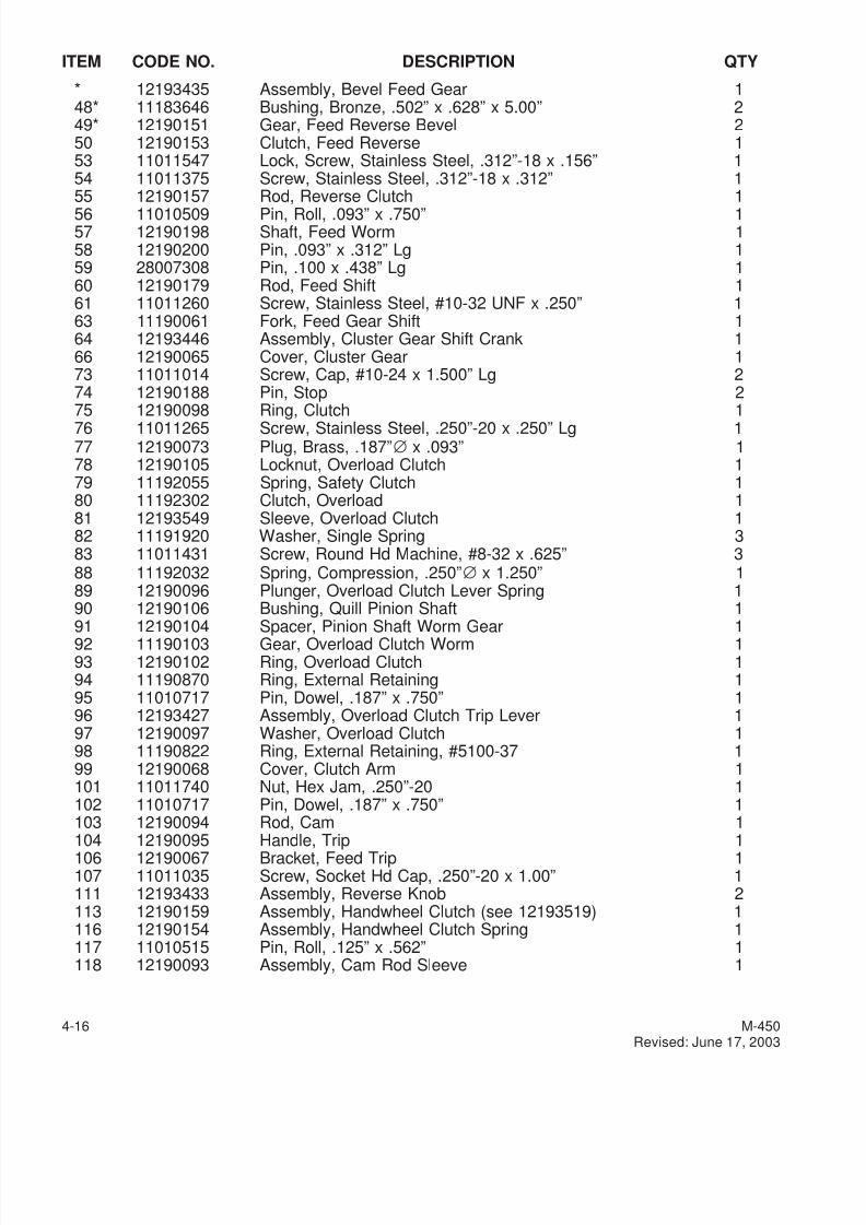
7/28/2019 FullManual Manual Bridgeport
http://slidepdf.com/reader/full/fullmanual-manual-bridgeport 78/134
ITEM CODE NO. DESCRIPTION QTY
* 12193435 Assembly, Bevel Feed Gear 148* 11183646 Bushing, Bronze, .502” x .628” x 5.00” 249* 12190151 Gear, Feed Reverse Bevel 250 12190153 Clutch, Feed Reverse 153 11011547 Lock, Screw, Stainless Steel, .312”-18 x .156” 154 11011375 Screw, Stainless Steel, .312”-18 x .312” 155 12190157 Rod, Reverse Clutch 1
56 11010509 Pin, Roll, .093” x .750” 157 12190198 Shaft, Feed Worm 158 12190200 Pin, .093” x .312” Lg 159 28007308 Pin, .100 x .438” Lg 160 12190179 Rod, Feed Shift 161 11011260 Screw, Stainless Steel, #10-32 UNF x .250” 163 11190061 Fork, Feed Gear Shift 164 12193446 Assembly, Cluster Gear Shift Crank 166 12190065 Cover, Cluster Gear 173 11011014 Screw, Cap, #10-24 x 1.500” Lg 274 12190188 Pin, Stop 275 12190098 Ring, Clutch 176 11011265 Screw, Stainless Steel, .250”-20 x .250” Lg 177 12190073 Plug, Brass, .187”∅ x .093” 178 12190105 Locknut, Overload Clutch 179 11192055 Spring, Safety Clutch 180 11192302 Clutch, Overload 181 12193549 Sleeve, Overload Clutch 182 11191920 Washer, Single Spring 383 11011431 Screw, Round Hd Machine, #8-32 x .625” 388 11192032 Spring, Compression, .250”∅ x 1.250” 189 12190096 Plunger, Overload Clutch Lever Spring 190 12190106 Bushing, Quill Pinion Shaft 1
91 12190104 Spacer, Pinion Shaft Worm Gear 192 11190103 Gear, Overload Clutch Worm 193 12190102 Ring, Overload Clutch 194 11190870 Ring, External Retaining 195 11010717 Pin, Dowel, .187” x .750” 196 12193427 Assembly, Overload Clutch Trip Lever 197 12190097 Washer, Overload Clutch 198 11190822 Ring, External Retaining, #5100-37 199 12190068 Cover, Clutch Arm 1101 11011740 Nut, Hex Jam, .250”-20 1102 11010717 Pin, Dowel, .187” x .750” 1103 12190094 Rod, Cam 1
104 12190095 Handle, Trip 1106 12190067 Bracket, Feed Trip 1107 11011035 Screw, Socket Hd Cap, .250”-20 x 1.00” 1111 12193433 Assembly, Reverse Knob 2113 12190159 Assembly, Handwheel Clutch (see 12193519) 1116 12190154 Assembly, Handwheel Clutch Spring 1117 11010515 Pin, Roll, .125” x .562” 1118 12190093 Assembly, Cam Rod Sleeve 1
4-16 M-450Revised: June 17, 2003
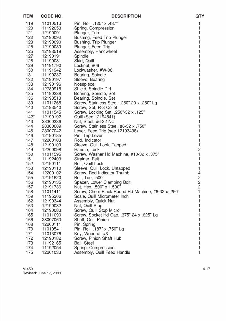
7/28/2019 FullManual Manual Bridgeport
http://slidepdf.com/reader/full/fullmanual-manual-bridgeport 79/134
ITEM CODE NO. DESCRIPTION QTY
119 11010513 Pin, Roll, .125” x .437” 1120 11192053 Spring, Compression 1121 12190091 Plunger, Trip 1122 12190092 Bushing, Feed Trip Plunger 1123 12190090 Bushing, Trip Plunger 1125 12190089 Plunger, Feed Trip 1125 12193519 Assembly, Handwheel 1
127 12190191 Spindle 1128 11190081 Skirt, Quill 1129 11191790 Locknut, #06 1130 11191942 Lockwasher, #W-06 1131 11190237 Bearing, Spindle 1132 12190197 Sleeve, Bearing 1133 12190196 Nosepiece 1134 12780915 Shield, Spindle Dirt 1135 11190238 Bearing, Spindle, Set 1136 12193513 Bearing, Spindle, Set 1139 11011265 Screw, Stainless Steel, .250”-20 x .250” Lg 1140 12193540 Screw, Set, R-8 Collet 1141 11011545 Screw, Locking Set, .250”-32 x .125” 1142* 12190192 Quill (See 12194541) 1143 28300336 Nut, Steel, #6-32 NC 1144 28300609 Screw, Stainless Steel, #6-32 x .750” 1145 28007042 Lever, Feed Trip (see 12193498) 1146 12190185 Pin, Trip Lever 1147 12200103 Rod, Indicator 1148 12190109 Sleeve, Quill Lock, Tapped 1149 12200098 Handle, Lock 2150 11011595 Screw, Washer Hd Machine, #10-32 x .375” 1151 11192403 Strainer, Felt 1
152 12190111 Bolt, Quill Lock 1153 12190110 Sleeve, Quill Lock, Untapped 1154 12200102 Screw, Rod Indicator Thumb 4155 12191620 Bolt, Tee, .500” 2156 12190135 Spacer, Lower Clamping Bolt 2157 12191736 Nut, Hex, .500” x 1.500” 2158 11011411 Screw, Chem Black Round Hd Machine, #6-32 x .250” 1159 11195306 Scale, Quill Micrometer Inch 1162 12190344 Assembly, Quick Nut 1163 12190082 Nut, Quill Stop 1164 12190083 Screw, Quill Stop Micro 1165 11011090 Screw, Socket Hd Cap, .375”-24 x .625” Lg 1
166 28007063 Shaft, Quill Pinion 1168 12200111 Pin, Spring 1170 11010541 Pin, Roll, .187” x .750” Lg 1171 11013076 Key, Woodruff #3 1172 12190182 Screw, Pinion Shaft Hub 1173 11192165 Ball, Steel 1174 11192054 Spring, Compression 1175 12201033 Assembly, Quill Feed Handle 1
M-450 4-17Revised: June 17, 2003
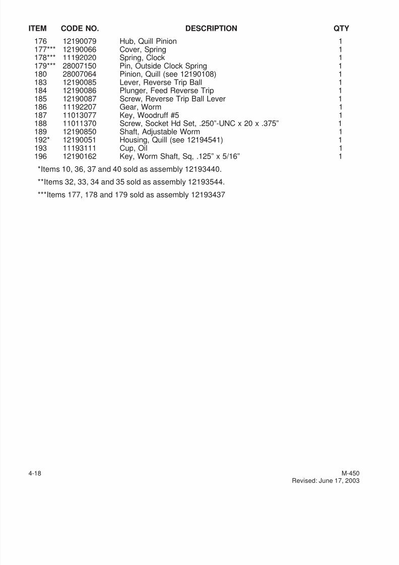
7/28/2019 FullManual Manual Bridgeport
http://slidepdf.com/reader/full/fullmanual-manual-bridgeport 80/134
ITEM CODE NO. DESCRIPTION QTY
176 12190079 Hub, Quill Pinion 1177*** 12190066 Cover, Spring 1178*** 11192020 Spring, Clock 1179*** 28007150 Pin, Outside Clock Spring 1180 28007064 Pinion, Quill (see 12190108) 1183 12190085 Lever, Reverse Trip Ball 1184 12190086 Plunger, Feed Reverse Trip 1
185 12190087 Screw, Reverse Trip Ball Lever 1186 11192207 Gear, Worm 1187 11013077 Key, Woodruff #5 1188 11011370 Screw, Socket Hd Set, .250”-UNC x 20 x .375” 1189 12190850 Shaft, Adjustable Worm 1192* 12190051 Housing, Quill (see 12194541) 1193 11193111 Cup, Oil 1196 12190162 Key, Worm Shaft, Sq, .125” x 5/16” 1
*Items 10, 36, 37 and 40 sold as assembly 12193440.
**Items 32, 33, 34 and 35 sold as assembly 12193544.
***Items 177, 178 and 179 sold as assembly 12193437
4-18 M-450Revised: June 17, 2003
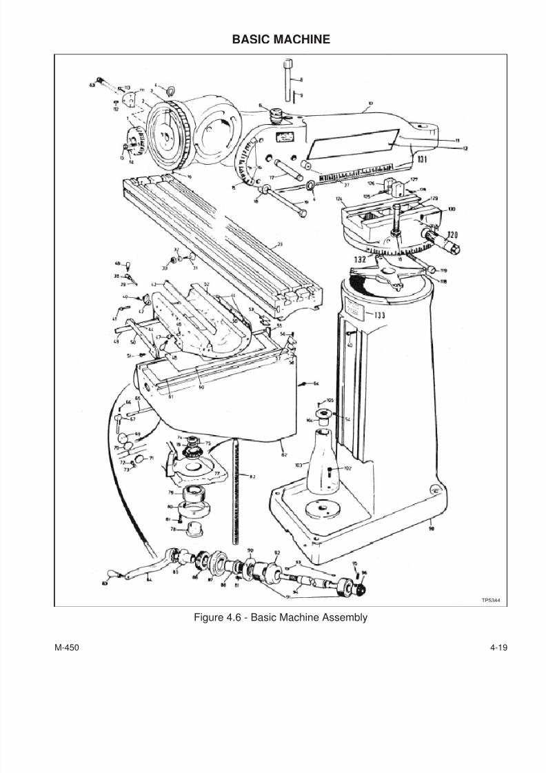
7/28/2019 FullManual Manual Bridgeport
http://slidepdf.com/reader/full/fullmanual-manual-bridgeport 81/134
BASIC MACHINE
M-450 4-19
Figure 4.6 - Basic Machine Assembly
TP5344
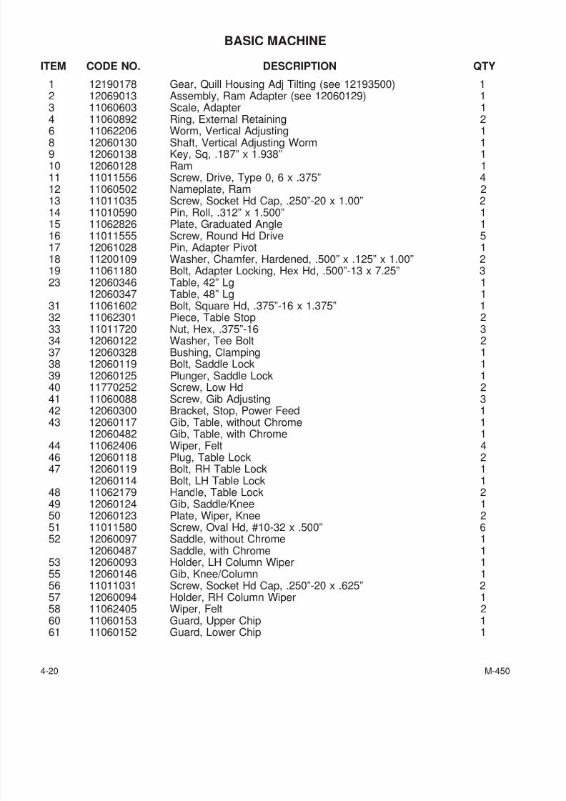
7/28/2019 FullManual Manual Bridgeport
http://slidepdf.com/reader/full/fullmanual-manual-bridgeport 82/134
BASIC MACHINE
ITEM CODE NO. DESCRIPTION QTY
1 12190178 Gear, Quill Housing Adj Tilting (see 12193500) 12 12069013 Assembly, Ram Adapter (see 12060129) 13 11060603 Scale, Adapter 14 11060892 Ring, External Retaining 26 11062206 Worm, Vertical Adjusting 18 12060130 Shaft, Vertical Adjusting Worm 19 12060138 Key, Sq, .187” x 1.938” 110 12060128 Ram 111 11011556 Screw, Drive, Type 0, 6 x .375” 412 11060502 Nameplate, Ram 213 11011035 Screw, Socket Hd Cap, .250”-20 x 1.00” 214 11010590 Pin, Roll, .312” x 1.500” 115 11062826 Plate, Graduated Angle 116 11011555 Screw, Round Hd Drive 517 12061028 Pin, Adapter Pivot 118 11200109 Washer, Chamfer, Hardened, .500” x .125” x 1.00” 2
19 11061180 Bolt, Adapter Locking, Hex Hd, .500”-13 x 7.25” 323 12060346 Table, 42” Lg 112060347 Table, 48” Lg 1
31 11061602 Bolt, Square Hd, .375”-16 x 1.375” 132 11062301 Piece, Table Stop 233 11011720 Nut, Hex, .375”-16 334 12060122 Washer, Tee Bolt 237 12060328 Bushing, Clamping 138 12060119 Bolt, Saddle Lock 139 12060125 Plunger, Saddle Lock 140 11770252 Screw, Low Hd 241 11060088 Screw, Gib Adjusting 3
42 12060300 Bracket, Stop, Power Feed 143 12060117 Gib, Table, without Chrome 1
12060482 Gib, Table, with Chrome 144 11062406 Wiper, Felt 446 12060118 Plug, Table Lock 247 12060119 Bolt, RH Table Lock 1
12060114 Bolt, LH Table Lock 148 11062179 Handle, Table Lock 249 12060124 Gib, Saddle/Knee 150 12060123 Plate, Wiper, Knee 251 11011580 Screw, Oval Hd, #10-32 x .500” 652 12060097 Saddle, without Chrome 1
12060487 Saddle, with Chrome 153 12060093 Holder, LH Column Wiper 155 12060146 Gib, Knee/Column 156 11011031 Screw, Socket Hd Cap, .250”-20 x .625” 257 12060094 Holder, RH Column Wiper 158 11062405 Wiper, Felt 260 11060153 Guard, Upper Chip 161 11060152 Guard, Lower Chip 1
4-20 M-450
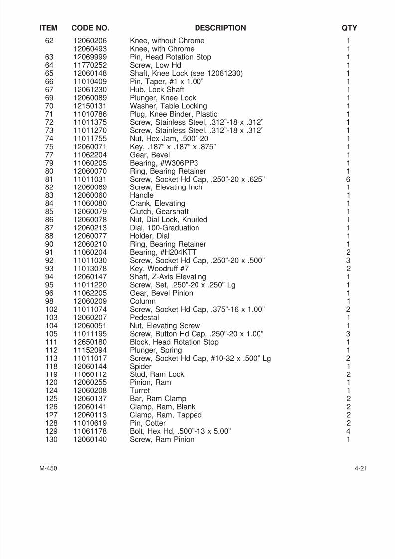
7/28/2019 FullManual Manual Bridgeport
http://slidepdf.com/reader/full/fullmanual-manual-bridgeport 83/134
ITEM CODE NO. DESCRIPTION QTY
62 12060206 Knee, without Chrome 112060493 Knee, with Chrome 1
63 12069999 Pin, Head Rotation Stop 164 11770252 Screw, Low Hd 165 12060148 Shaft, Knee Lock (see 12061230) 166 11010409 Pin, Taper, #1 x 1.00” 167 12061230 Hub, Lock Shaft 1
69 12060089 Plunger, Knee Lock 170 12150131 Washer, Table Locking 171 11010786 Plug, Knee Binder, Plastic 172 11011375 Screw, Stainless Steel, .312”-18 x .312” 173 11011270 Screw, Stainless Steel, .312”-18 x .312” 174 11011755 Nut, Hex Jam, .500”-20 175 12060071 Key, .187” x .187” x .875” 177 11062204 Gear, Bevel 179 11060205 Bearing, #W306PP3 180 12060070 Ring, Bearing Retainer 181 11011031 Screw, Socket Hd Cap, .250”-20 x .625” 682 12060069 Screw, Elevating Inch 183 12060060 Handle 184 11060080 Crank, Elevating 185 12060079 Clutch, Gearshaft 186 12060078 Nut, Dial Lock, Knurled 187 12060213 Dial, 100-Graduation 188 12060077 Holder, Dial 190 12060210 Ring, Bearing Retainer 191 11060204 Bearing, #H204KTT 292 11011030 Screw, Socket Hd Cap, .250”-20 x .500” 393 11013078 Key, Woodruff #7 294 12060147 Shaft, Z-Axis Elevating 1
95 11011220 Screw, Set, .250”-20 x .250” Lg 196 11062205 Gear, Bevel Pinion 198 12060209 Column 1102 11011074 Screw, Socket Hd Cap, .375”-16 x 1.00” 2103 12060207 Pedestal 1104 12060051 Nut, Elevating Screw 1105 11011195 Screw, Button Hd Cap, .250”-20 x 1.00” 3111 12650180 Block, Head Rotation Stop 1112 11152094 Plunger, Spring 1113 11011017 Screw, Socket Hd Cap, #10-32 x .500” Lg 2118 12060144 Spider 1119 11060112 Stud, Ram Lock 2
120 12060255 Pinion, Ram 1124 12060208 Turret 1125 12060137 Bar, Ram Clamp 2126 12060141 Clamp, Ram, Blank 2127 12060113 Clamp, Ram, Tapped 2128 11010619 Pin, Cotter 2129 11061178 Bolt, Hex Hd, .500”-13 x 5.00” 4130 12060140 Screw, Ram Pinion 1
M-450 4-21

7/28/2019 FullManual Manual Bridgeport
http://slidepdf.com/reader/full/fullmanual-manual-bridgeport 84/134
ITEM CODE NO. DESCRIPTION QTY
131 11060602 Scale, Ram 111980426 Screw, Drive, Type U, #4 x .312” 2
132 11060601 Turret, Scale 111989426 Screw, Drive 2
133 11010200 Nameplate, Warning 111980426 Screw, Drive, Type U, #4 x .312” 4
4-22 M-450
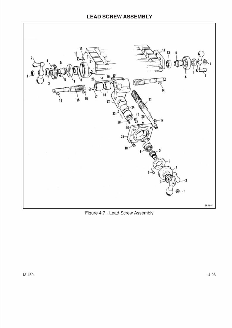
7/28/2019 FullManual Manual Bridgeport
http://slidepdf.com/reader/full/fullmanual-manual-bridgeport 85/134
LEAD SCREW ASSEMBLY
M-450 4-23
Figure 4.7 - Lead Screw Assembly
TP5345
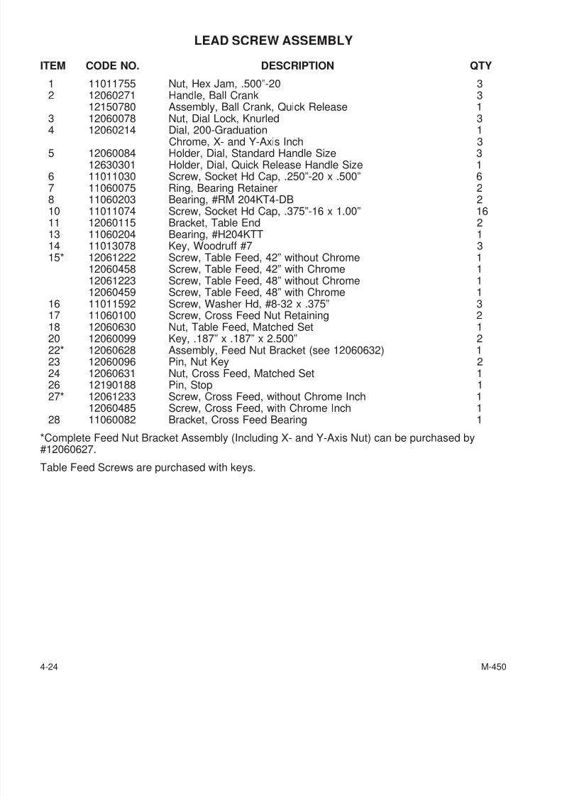
7/28/2019 FullManual Manual Bridgeport
http://slidepdf.com/reader/full/fullmanual-manual-bridgeport 86/134
LEAD SCREW ASSEMBLY
ITEM CODE NO. DESCRIPTION QTY
1 11011755 Nut, Hex Jam, .500”-20 32 12060271 Handle, Ball Crank 3
12150780 Assembly, Ball Crank, Quick Release 13 12060078 Nut, Dial Lock, Knurled 34 12060214 Dial, 200-Graduation 1
Chrome, X- and Y-Axis Inch 35 12060084 Holder, Dial, Standard Handle Size 3
12630301 Holder, Dial, Quick Release Handle Size 16 11011030 Screw, Socket Hd Cap, .250”-20 x .500” 67 11060075 Ring, Bearing Retainer 28 11060203 Bearing, #RM 204KT4-DB 210 11011074 Screw, Socket Hd Cap, .375”-16 x 1.00” 1611 12060115 Bracket, Table End 213 11060204 Bearing, #H204KTT 114 11013078 Key, Woodruff #7 315* 12061222 Screw, Table Feed, 42” without Chrome 1
12060458 Screw, Table Feed, 42” with Chrome 112061223 Screw, Table Feed, 48” without Chrome 112060459 Screw, Table Feed, 48” with Chrome 1
16 11011592 Screw, Washer Hd, #8-32 x .375” 317 11060100 Screw, Cross Feed Nut Retaining 218 12060630 Nut, Table Feed, Matched Set 120 12060099 Key, .187” x .187” x 2.500” 222* 12060628 Assembly, Feed Nut Bracket (see 12060632) 123 12060096 Pin, Nut Key 224 12060631 Nut, Cross Feed, Matched Set 126 12190188 Pin, Stop 127* 12061233 Screw, Cross Feed, without Chrome Inch 1
12060485 Screw, Cross Feed, with Chrome Inch 128 11060082 Bracket, Cross Feed Bearing 1
*Complete Feed Nut Bracket Assembly (Including X- and Y-Axis Nut) can be purchased by#12060627.
Table Feed Screws are purchased with keys.
4-24 M-450
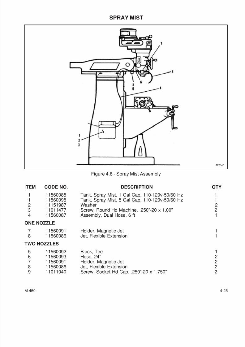
7/28/2019 FullManual Manual Bridgeport
http://slidepdf.com/reader/full/fullmanual-manual-bridgeport 87/134
SPRAY MIST
ITEM CODE NO. DESCRIPTION QTY
1 11560085 Tank, Spray Mist, 1 Gal Cap, 110-120v-50/60 Hz 11 11560095 Tank, Spray Mist, 5 Gal Cap, 110-120v-50/60 Hz 12 11151987 Washer 23 11011477 Screw, Round Hd Machine, .250”-20 x 1.00” 24 11560087 Assembly, Dual Hose, 6 ft 1
ONE NOZZLE
7 11560091 Holder, Magnetic Jet 1
8 11560086 Jet, Flexible Extension 1TWO NOZZLES
5 11560092 Block, Tee 16 11560093 Hose, 24” 27 11560091 Holder, Magnetic Jet 28 11560086 Jet, Flexible Extension 29 11011040 Screw, Socket Hd Cap, .250”-20 x 1.750” 2
M-450 4-25
Figure 4.8 - Spray Mist Assembly
TP5346
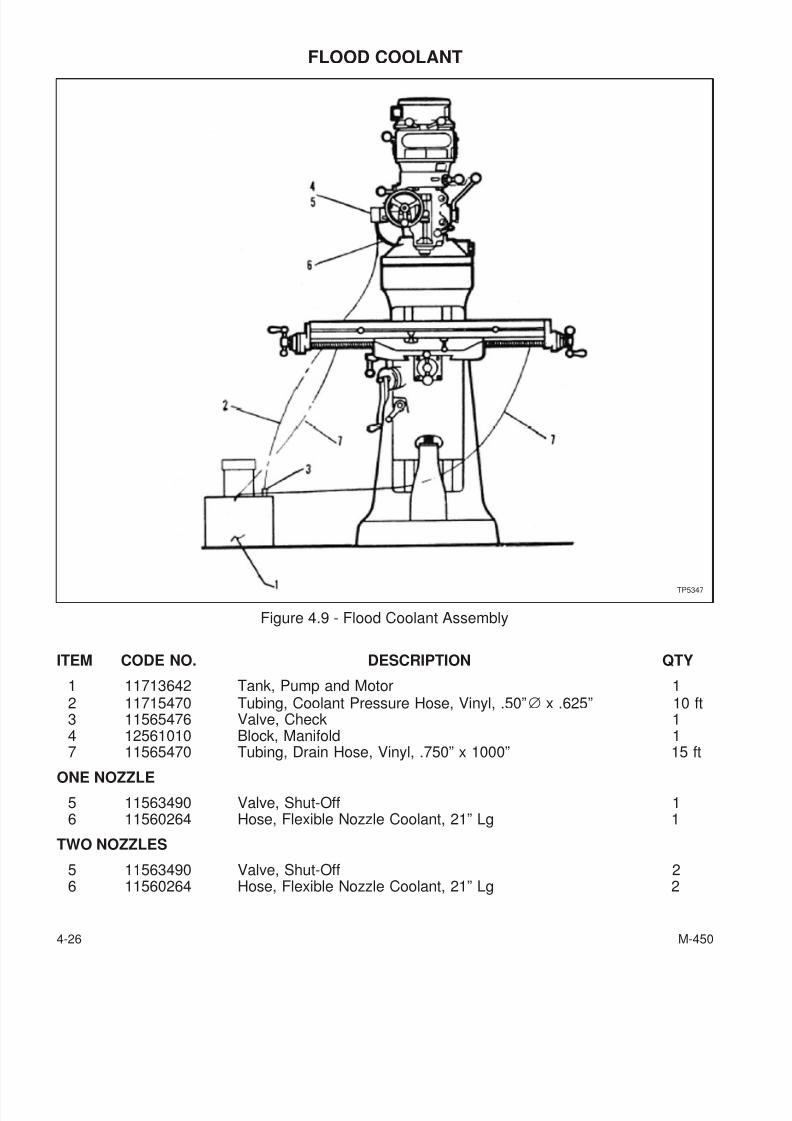
7/28/2019 FullManual Manual Bridgeport
http://slidepdf.com/reader/full/fullmanual-manual-bridgeport 88/134
FLOOD COOLANT
ITEM CODE NO. DESCRIPTION QTY
1 11713642 Tank, Pump and Motor 12 11715470 Tubing, Coolant Pressure Hose, Vinyl, .50”∅ x .625” 10 ft3 11565476 Valve, Check 14 12561010 Block, Manifold 17 11565470 Tubing, Drain Hose, Vinyl, .750” x 1000” 15 ft
ONE NOZZLE
5 11563490 Valve, Shut-Off 16 11560264 Hose, Flexible Nozzle Coolant, 21” Lg 1
TWO NOZZLES
5 11563490 Valve, Shut-Off 26 11560264 Hose, Flexible Nozzle Coolant, 21” Lg 2
4-26 M-450
Figure 4.9 - Flood Coolant Assembly
TP5347
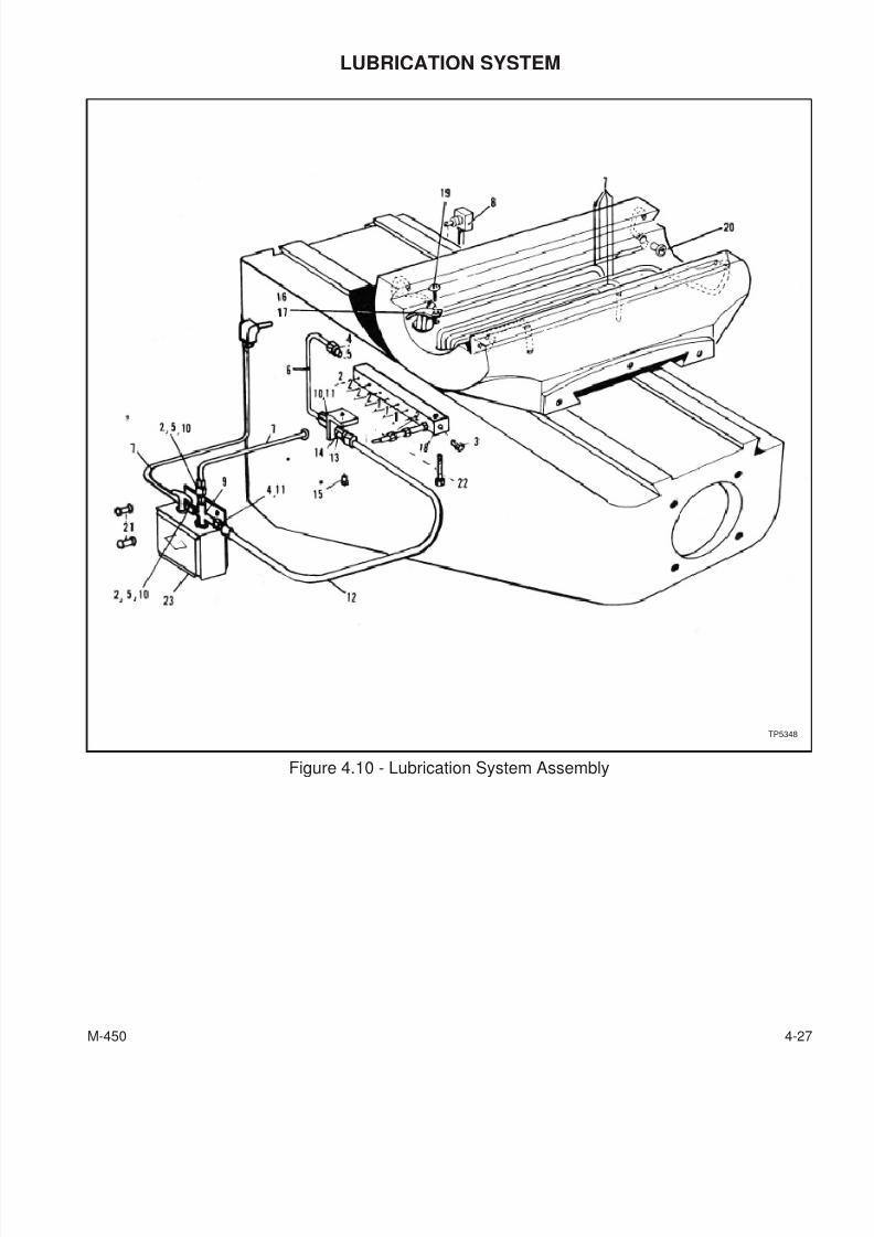
7/28/2019 FullManual Manual Bridgeport
http://slidepdf.com/reader/full/fullmanual-manual-bridgeport 89/134
LUBRICATION SYSTEM
M-450 4-27
Figure 4.10 - Lubrication System Assembly
TP5348
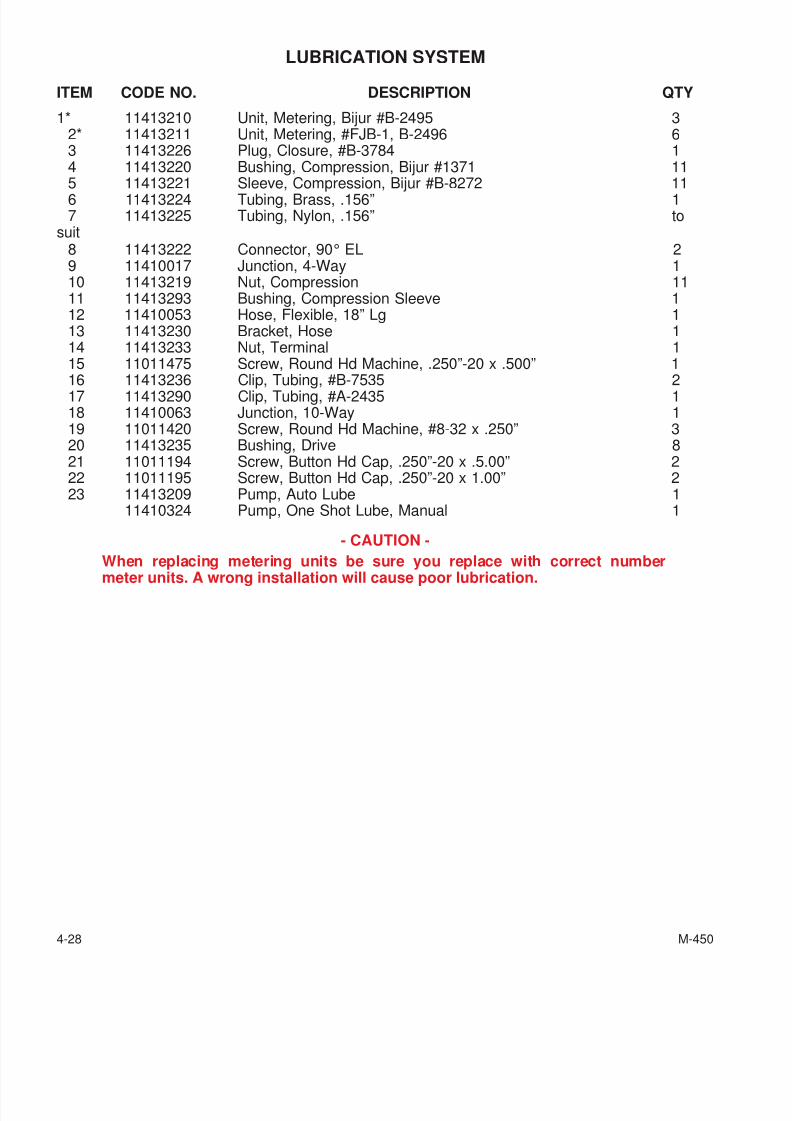
7/28/2019 FullManual Manual Bridgeport
http://slidepdf.com/reader/full/fullmanual-manual-bridgeport 90/134
LUBRICATION SYSTEM
ITEM CODE NO. DESCRIPTION QTY
1* 11413210 Unit, Metering, Bijur #B-2495 32* 11413211 Unit, Metering, #FJB-1, B-2496 63 11413226 Plug, Closure, #B-3784 14 11413220 Bushing, Compression, Bijur #1371 115 11413221 Sleeve, Compression, Bijur #B-8272 116 11413224 Tubing, Brass, .156” 17 11413225 Tubing, Nylon, .156” to
suit8 11413222 Connector, 90° EL 29 11410017 Junction, 4-Way 110 11413219 Nut, Compression 1111 11413293 Bushing, Compression Sleeve 112 11410053 Hose, Flexible, 18” Lg 113 11413230 Bracket, Hose 114 11413233 Nut, Terminal 115 11011475 Screw, Round Hd Machine, .250”-20 x .500” 1
16 11413236 Clip, Tubing, #B-7535 217 11413290 Clip, Tubing, #A-2435 118 11410063 Junction, 10-Way 119 11011420 Screw, Round Hd Machine, #8-32 x .250” 320 11413235 Bushing, Drive 821 11011194 Screw, Button Hd Cap, .250”-20 x .5.00” 222 11011195 Screw, Button Hd Cap, .250”-20 x 1.00” 223 11413209 Pump, Auto Lube 1
11410324 Pump, One Shot Lube, Manual 1
- CAUTION -
When replacing metering units be sure you replace with correct number
meter units. A wrong installation will cause poor lubrication.
4-28 M-450
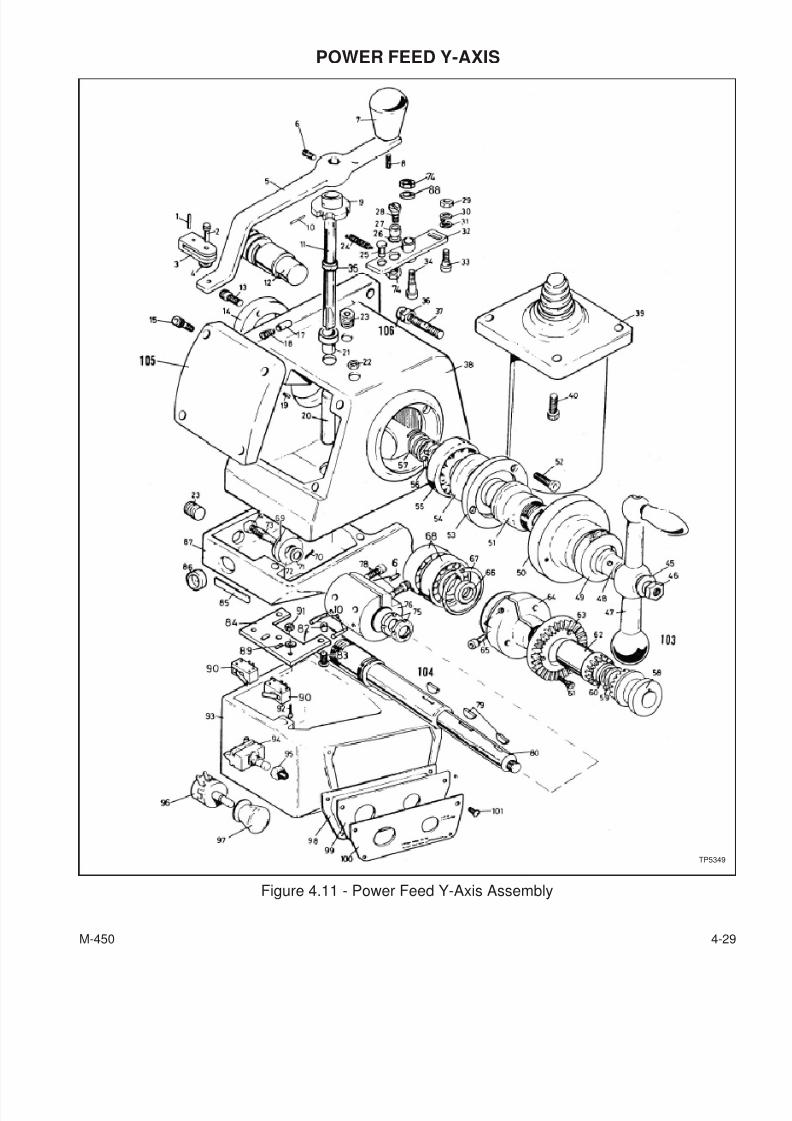
7/28/2019 FullManual Manual Bridgeport
http://slidepdf.com/reader/full/fullmanual-manual-bridgeport 91/134
POWER FEED Y-AXIS
M-450 4-29
Figure 4.11 - Power Feed Y-Axis Assembly
TP5349
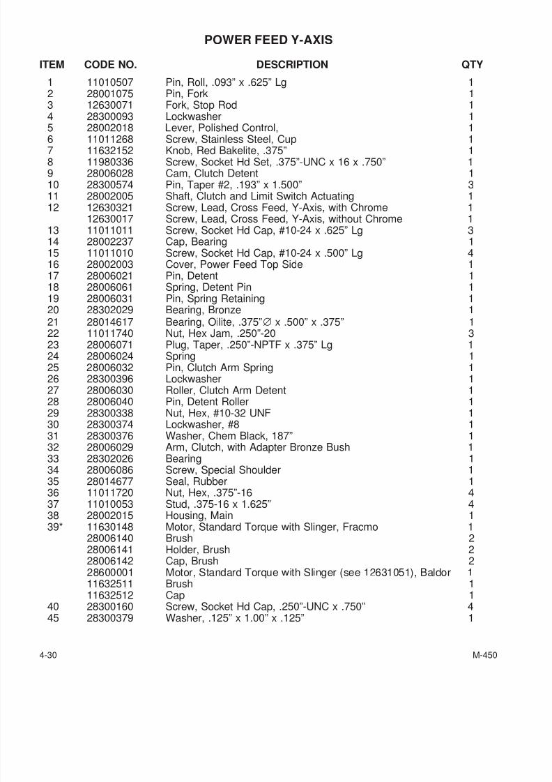
7/28/2019 FullManual Manual Bridgeport
http://slidepdf.com/reader/full/fullmanual-manual-bridgeport 92/134
POWER FEED Y-AXIS
ITEM CODE NO. DESCRIPTION QTY
1 11010507 Pin, Roll, .093” x .625” Lg 12 28001075 Pin, Fork 13 12630071 Fork, Stop Rod 14 28300093 Lockwasher 15 28002018 Lever, Polished Control, 16 11011268 Screw, Stainless Steel, Cup 17 11632152 Knob, Red Bakelite, .375” 18 11980336 Screw, Socket Hd Set, .375”-UNC x 16 x .750” 19 28006028 Cam, Clutch Detent 110 28300574 Pin, Taper #2, .193” x 1.500” 311 28002005 Shaft, Clutch and Limit Switch Actuating 112 12630321 Screw, Lead, Cross Feed, Y-Axis, with Chrome 1
12630017 Screw, Lead, Cross Feed, Y-Axis, without Chrome 113 11011011 Screw, Socket Hd Cap, #10-24 x .625” Lg 314 28002237 Cap, Bearing 115 11011010 Screw, Socket Hd Cap, #10-24 x .500” Lg 4
16 28002003 Cover, Power Feed Top Side 117 28006021 Pin, Detent 118 28006061 Spring, Detent Pin 119 28006031 Pin, Spring Retaining 120 28302029 Bearing, Bronze 121 28014617 Bearing, Oilite, .375”∅ x .500” x .375” 122 11011740 Nut, Hex Jam, .250”-20 323 28006071 Plug, Taper, .250”-NPTF x .375” Lg 124 28006024 Spring 125 28006032 Pin, Clutch Arm Spring 126 28300396 Lockwasher 127 28006030 Roller, Clutch Arm Detent 1
28 28006040 Pin, Detent Roller 129 28300338 Nut, Hex, #10-32 UNF 130 28300374 Lockwasher, #8 131 28300376 Washer, Chem Black, 187” 132 28006029 Arm, Clutch, with Adapter Bronze Bush 133 28302026 Bearing 134 28006086 Screw, Special Shoulder 135 28014677 Seal, Rubber 136 11011720 Nut, Hex, .375”-16 437 11010053 Stud, .375-16 x 1.625” 438 28002015 Housing, Main 139* 11630148 Motor, Standard Torque with Slinger, Fracmo 1
28006140 Brush 228006141 Holder, Brush 228006142 Cap, Brush 228600001 Motor, Standard Torque with Slinger (see 12631051), Baldor 111632511 Brush 111632512 Cap 1
40 28300160 Screw, Socket Hd Cap, .250”-UNC x .750” 445 28300379 Washer, .125” x 1.00” x .125” 1
4-30 M-450
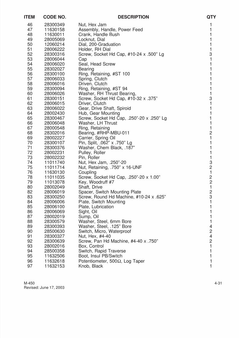
7/28/2019 FullManual Manual Bridgeport
http://slidepdf.com/reader/full/fullmanual-manual-bridgeport 93/134
ITEM CODE NO. DESCRIPTION QTY
46 28300349 Nut, Hex Jam 147 11630158 Assembly, Handle, Power Feed 148 11630011 Crank, Handle Bush 149 28005069 Locknut, Dial 150 12060214 Dial, 200-Graduation 151 28006222 Holder, RH Dial 152 28300316 Screw, Socket Hd Cap, #10-24 x .500” Lg 3
53 28006044 Cap 154 28006020 Seal, Head Screw 155 28302027 Bearing 156 28300100 Ring, Retaining, #ST 100 157 28006033 Spring, Clutch 158 28006016 Driven, Clutch 159 28300094 Ring, Retaining, #ST 94 160 28006026 Washer, RH Thrust Bearing, 161 28300151 Screw, Socket Hd Cap, #10-32 x .375” 362 28006015 Driver, Clutch 163 28006022 Gear, Drive Shaft, Spiroid 164 28002430 Hub, Gear Mounting 165 28300467 Screw, Socket Hd Cap, .250”-20 x .250” Lg 166 28006048 Washer, LH Thrust 167 28000548 Ring, Retaining 168 28302016 Bearing, #RHP-MBU-011 269 28002227 Carrier, Spring Oil 170 28300107 Pin, Split, .062” x .750” Lg 171 28300376 Washer, Chem Black, .187” 172 28002231 Pulley, Roller 173 28002232 Pin, Roller 174 11011740 Nut, Hex Jam, .250”-20 375 11011714 Nut, Retaining, .750” x 16-UNF 2
76 11630130 Coupling 178 11011035 Screw, Socket Hd Cap, .250”-20 x 1.00” 279 11013078 Key, Woodruff #7 280 28002049 Shaft, Drive 182 28006019 Spacer, Switch Mounting Plate 283 28300250 Screw, Round Hd Machine, #10-24 x .625” 384 28006006 Plate, Switch Mounting 185 28006100 Plate, Lubrication 186 28006069 Sight, Oil 187 28002019 Sump, Oil 188 28300579 Washer, Steel, 6mm Bore 189 28300393 Washer, Steel, .125” Bore 4
90 28500630 Switch, Micro, Waterproof 291 28300327 Nut, Hex, #4-40 492 28300639 Screw, Pan Hd Machine, #4-40 x .750” 293 28002016 Box, Control 194 28500358 Switch, Rapid Traverse 195 11632506 Boot, Insul PB/Switch 196 11632618 Potentiometer, 500Ω, Log Taper 197 11632153 Knob, Black 1
M-450 4-31Revised: June 17, 2003

7/28/2019 FullManual Manual Bridgeport
http://slidepdf.com/reader/full/fullmanual-manual-bridgeport 94/134
ITEM CODE NO. DESCRIPTION QTY
98 28006280 Gasket, Control Box 199 28006004 Cover, Control Box 1100 28006281 Plate, Control Box Scale 1101 28300206 Screw, Button Hd Cap, #8-32 x .500” Lg 4102 12630033 Rod, Stop 1103 11630224 Handle, Ball 1104 11013089 Key, Woodruff #11 1
105 28014616 Gasket, Power Feed Cover 1106 11181981 Washer, .875” x .375” x .064” 4
* Baldor Boehm motor assemblies are interchangeable with Fracmo motor assemblies.
4-32 M-450
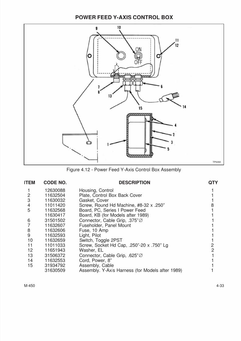
7/28/2019 FullManual Manual Bridgeport
http://slidepdf.com/reader/full/fullmanual-manual-bridgeport 95/134
POWER FEED Y-AXIS CONTROL BOX
ITEM CODE NO. DESCRIPTION QTY
1 12630088 Housing, Control 12 11632504 Plate, Control Box Back Cover 13 11630032 Gasket, Cover 14 11011420 Screw, Round Hd Machine, #8-32 x .250” 85 11632568 Board, PC, Series I Power Feed 1
11630417 Board, KB (for Models after 1989) 16 31501502 Connector, Cable Grip, .375”∅ 17 11632607 Fuseholder, Panel Mount 18 11632606 Fuse, 10 Amp 1
9 11632593 Light, Pilot 110 11632659 Switch, Toggle 2PST 111 11011033 Screw, Socket Hd Cap, .250”-20 x .750” Lg 212 11651943 Washer, EL 213 31506372 Connector, Cable Grip, .625”∅ 114 11632553 Cord, Power, 8” 115 31934792 Assembly, Cable 1
31630509 Assembly. Y-Axis Harness (for Models after 1989) 1
M-450 4-33
Figure 4.12 - Power Feed Y-Axis Control Box Assembly
TP5350
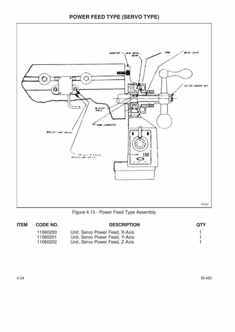
7/28/2019 FullManual Manual Bridgeport
http://slidepdf.com/reader/full/fullmanual-manual-bridgeport 96/134
POWER FEED TYPE (SERVO TYPE)
ITEM CODE NO. DESCRIPTION QTY
11060200 Unit, Servo Power Feed, X-Axis 111060201 Unit, Servo Power Feed, Y-Axis 111060202 Unit, Servo Power Feed, Z-Axis 1
4-34 M-450
Figure 4.13 - Power Feed Type Assembly
TP5351
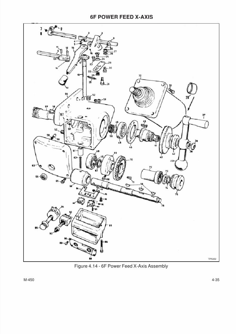
7/28/2019 FullManual Manual Bridgeport
http://slidepdf.com/reader/full/fullmanual-manual-bridgeport 97/134
6F POWER FEED X-AXIS
M-450 4-35
Figure 4.14 - 6F Power Feed X-Axis Assembly
TP5352
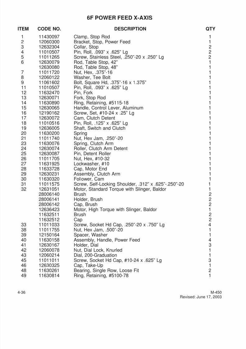
7/28/2019 FullManual Manual Bridgeport
http://slidepdf.com/reader/full/fullmanual-manual-bridgeport 98/134
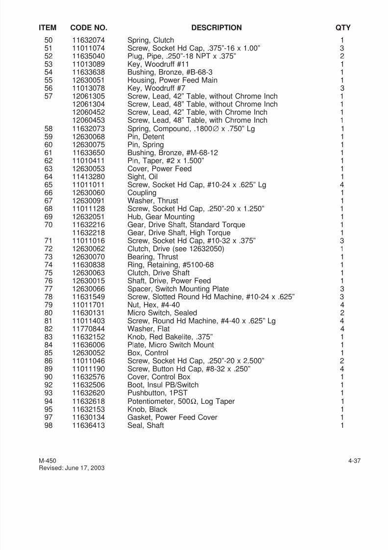
7/28/2019 FullManual Manual Bridgeport
http://slidepdf.com/reader/full/fullmanual-manual-bridgeport 99/134
ITEM CODE NO. DESCRIPTION QTY
50 11632074 Spring, Clutch 151 11011074 Screw, Socket Hd Cap, .375”-16 x 1.00” 352 11635040 Plug, Pipe, .250”-18 NPT x .375” 253 11013089 Key, Woodruff #11 154 11633638 Bushing, Bronze, #B-68-3 155 12630051 Housing, Power Feed Main 156 11013078 Key, Woodruff #7 3
57 12061305 Screw, Lead, 42” Table, without Chrome Inch 112061304 Screw, Lead, 48” Table, without Chrome Inch 112060452 Screw, Lead, 42” Table, with Chrome Inch 112060453 Screw, Lead, 48” Table, with Chrome Inch 1
58 11632073 Spring, Compound, .1800∅ x .750” Lg 159 12630068 Pin, Detent 160 12630075 Pin, Spring 161 11633650 Bushing, Bronze, #M-68-12 162 11010411 Pin, Taper, #2 x 1.500” 163 12630053 Cover, Power Feed 164 11413280 Sight, Oil 1
65 11011011 Screw, Socket Hd Cap, #10-24 x .625” Lg 466 12630060 Coupling 167 12630091 Washer, Thrust 168 11011128 Screw, Socket Hd Cap, .250”-20 x 1.250” 169 12632051 Hub, Gear Mounting 170 11632216 Gear, Drive Shaft, Standard Torque 1
11632218 Gear, Drive Shaft, High Torque 171 11011016 Screw, Socket Hd Cap, #10-32 x .375” 372 12630062 Clutch, Drive (see 12632050) 173 12630070 Bearing, Thrust 174 11630838 Ring, Retaining, #5100-68 175 12630063 Clutch, Drive Shaft 1
76 12630015 Shaft, Drive, Power Feed 177 12630066 Spacer, Switch Mounting Plate 378 11631549 Screw, Slotted Round Hd Machine, #10-24 x .625” 379 11011701 Nut, Hex, #4-40 480 11630131 Micro Switch, Sealed 281 11011403 Screw, Round Hd Machine, #4-40 x .625” Lg 482 11770844 Washer, Flat 483 11632152 Knob, Red Bakelite, .375” 184 11636006 Plate, Micro Switch Mount 185 12630052 Box, Control 186 11011046 Screw, Socket Hd Cap, .250”-20 x 2.500” 289 11011190 Screw, Button Hd Cap, #8-32 x .250” 4
90 11632576 Cover, Control Box 192 11632506 Boot, Insul PB/Switch 193 11632620 Pushbutton, 1PST 194 11632618 Potentiometer, 500Ω, Log Taper 195 11632153 Knob, Black 197 11630134 Gasket, Power Feed Cover 198 11636413 Seal, Shaft 1
M-450 4-37Revised: June 17, 2003
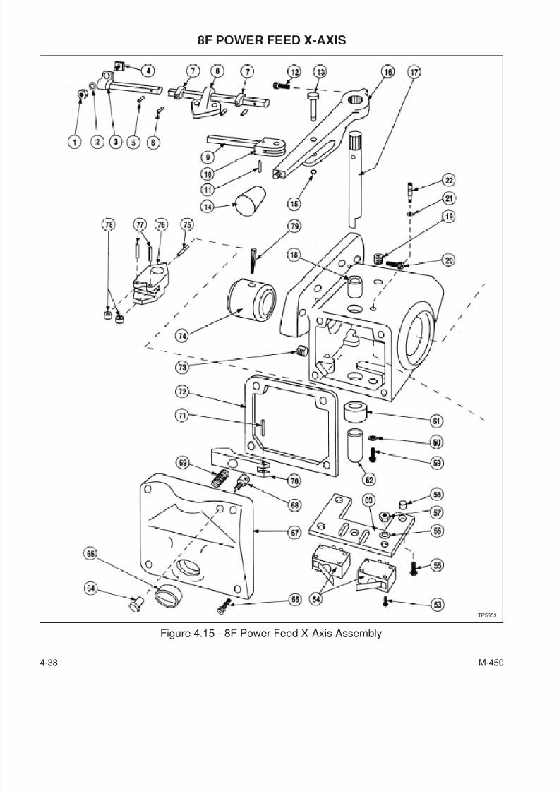
7/28/2019 FullManual Manual Bridgeport
http://slidepdf.com/reader/full/fullmanual-manual-bridgeport 100/134
8F POWER FEED X-AXIS
4-38 M-450
Figure 4.15 - 8F Power Feed X-Axis Assembly
TP5353
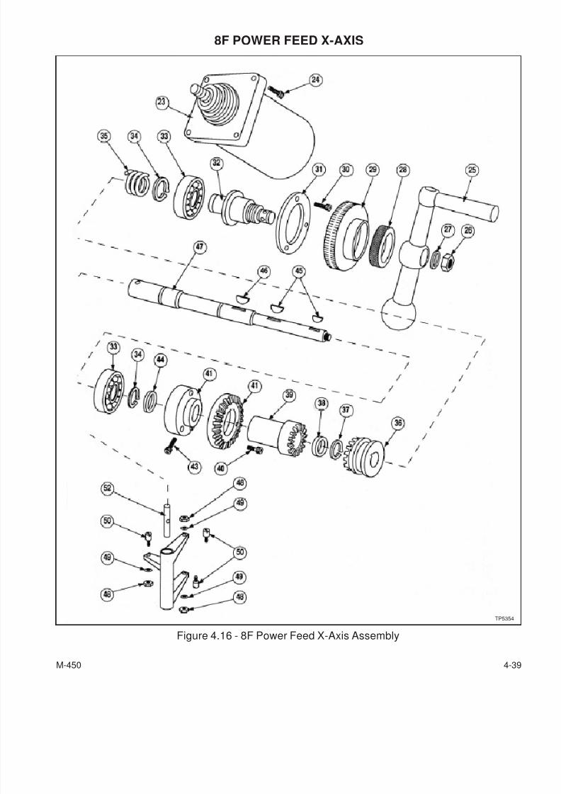
7/28/2019 FullManual Manual Bridgeport
http://slidepdf.com/reader/full/fullmanual-manual-bridgeport 101/134
8F POWER FEED X-AXIS
M-450 4-39
Figure 4.16 - 8F Power Feed X-Axis Assembly
TP5354
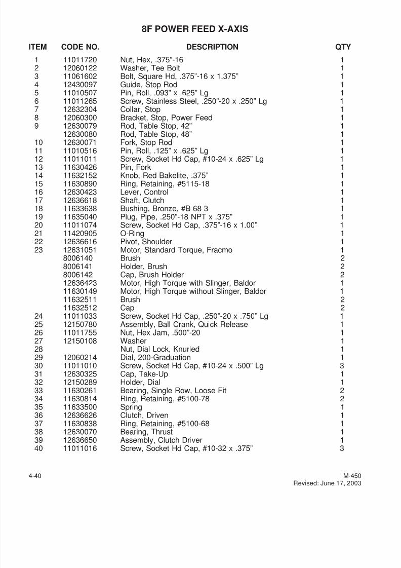
7/28/2019 FullManual Manual Bridgeport
http://slidepdf.com/reader/full/fullmanual-manual-bridgeport 102/134
8F POWER FEED X-AXIS
ITEM CODE NO. DESCRIPTION QTY
1 11011720 Nut, Hex, .375”-16 12 12060122 Washer, Tee Bolt 13 11061602 Bolt, Square Hd, .375”-16 x 1.375” 14 12430097 Guide, Stop Rod 15 11010507 Pin, Roll, .093” x .625” Lg 16 11011265 Screw, Stainless Steel, .250”-20 x .250” Lg 17 12632304 Collar, Stop 18 12060300 Bracket, Stop, Power Feed 19 12630079 Rod, Table Stop, 42” 1
12630080 Rod, Table Stop, 48” 110 12630071 Fork, Stop Rod 111 11010516 Pin, Roll, .125” x .625” Lg 112 11011011 Screw, Socket Hd Cap, #10-24 x .625” Lg 113 11630426 Pin, Fork 114 11632152 Knob, Red Bakelite, .375” 115 11630890 Ring, Retaining, #5115-18 1
16 12630423 Lever, Control 117 12636618 Shaft, Clutch 118 11633638 Bushing, Bronze, #B-68-3 119 11635040 Plug, Pipe, .250”-18 NPT x .375” 120 11011074 Screw, Socket Hd Cap, .375”-16 x 1.00” 121 11420905 O-Ring 122 12636616 Pivot, Shoulder 123 12631051 Motor, Standard Torque, Fracmo 1
8006140 Brush 28006141 Holder, Brush 28006142 Cap, Brush Holder 212636423 Motor, High Torque with Slinger, Baldor 1
11630149 Motor, High Torque without Slinger, Baldor 111632511 Brush 211632512 Cap 2
24 11011033 Screw, Socket Hd Cap, .250”-20 x .750” Lg 125 12150780 Assembly, Ball Crank, Quick Release 126 11011755 Nut, Hex Jam, .500”-20 127 12150108 Washer 128 Nut, Dial Lock, Knurled 129 12060214 Dial, 200-Graduation 130 11011010 Screw, Socket Hd Cap, #10-24 x .500” Lg 331 12630325 Cap, Take-Up 132 12150289 Holder, Dial 1
33 11630261 Bearing, Single Row, Loose Fit 234 11630814 Ring, Retaining, #5100-78 235 11633500 Spring 136 12636626 Clutch, Driven 137 11630838 Ring, Retaining, #5100-68 138 12630070 Bearing, Thrust 139 12636650 Assembly, Clutch Driver 140 11011016 Screw, Socket Hd Cap, #10-32 x .375” 3
4-40 M-450Revised: June 17, 2003
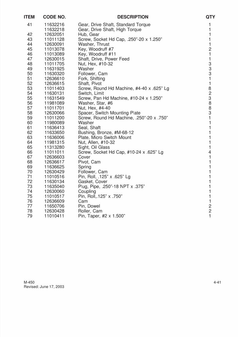
7/28/2019 FullManual Manual Bridgeport
http://slidepdf.com/reader/full/fullmanual-manual-bridgeport 103/134
ITEM CODE NO. DESCRIPTION QTY
41 11632216 Gear, Drive Shaft, Standard Torque 111632218 Gear, Drive Shaft, High Torque 1
42 12632051 Hub, Gear 143 11011128 Screw, Socket Hd Cap, .250”-20 x 1.250” 144 12630091 Washer, Thrust 145 11013078 Key, Woodruff #7 246 11013089 Key, Woodruff #11 1
47 12630015 Shaft, Drive, Power Feed 148 11011705 Nut, Hex, #10-32 349 11631925 Washer 350 11630320 Follower, Cam 351 12636610 Fork, Shifting 152 12636615 Shaft, Pivot 153 11011403 Screw, Round Hd Machine, #4-40 x .625” Lg 854 11630131 Switch, Limit 255 11631549 Screw, Pan Hd Machine, #10-24 x 1.250” 356 11981089 Washer, Star, #6 857 11011701 Nut, Hex, #4-40 858 12630066 Spacer, Switch Mounting Plate 359 11011200 Screw, Round Hd Machine, .250”-20 x .750” 160 11980089 Washer 161 11636413 Seal, Shaft 162 11633650 Bushing, Bronze, #M-68-12 163 11636006 Plate, Micro Switch Mount 164 11981315 Nut, Allen, #10-32 165 11313280 Sight, Oil Glass 166 11011011 Screw, Socket Hd Cap, #10-24 x .625” Lg 467 12636603 Cover 168 12636617 Pivot, Cam 169 11636625 Spring 1
70 12630429 Follower, Cam 171 11010516 Pin, Roll, .125” x .625” Lg 172 11630134 Gasket, Cover 173 11635040 Plug, Pipe, .250”-18 NPT x .375” 174 12630060 Coupling 175 11010517 Pin, Roll,.125” x .750” 176 12636609 Cam 177 11650706 Pin, Dowel 278 12630428 Roller, Cam 279 11010411 Pin, Taper, #2 x 1.500” 1
M-450 4-41Revised: June 17, 2003
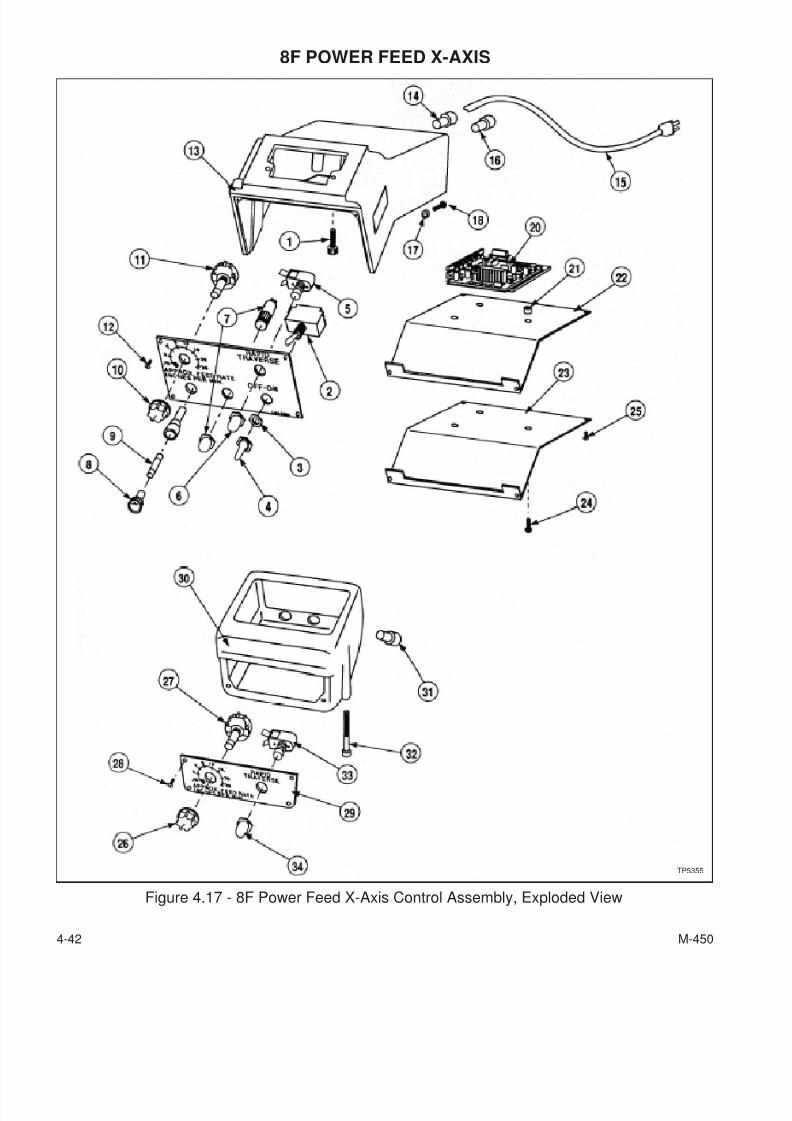
7/28/2019 FullManual Manual Bridgeport
http://slidepdf.com/reader/full/fullmanual-manual-bridgeport 104/134
8F POWER FEED X-AXIS
4-42 M-450
Figure 4.17 - 8F Power Feed X-Axis Control Assembly, Exploded View
TP5355
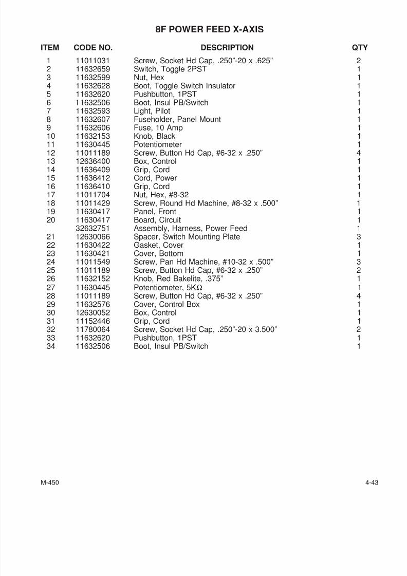
7/28/2019 FullManual Manual Bridgeport
http://slidepdf.com/reader/full/fullmanual-manual-bridgeport 105/134
8F POWER FEED X-AXIS
ITEM CODE NO. DESCRIPTION QTY
1 11011031 Screw, Socket Hd Cap, .250”-20 x .625” 22 11632659 Switch, Toggle 2PST 13 11632599 Nut, Hex 14 11632628 Boot, Toggle Switch Insulator 15 11632620 Pushbutton, 1PST 16 11632506 Boot, Insul PB/Switch 17 11632593 Light, Pilot 18 11632607 Fuseholder, Panel Mount 19 11632606 Fuse, 10 Amp 110 11632153 Knob, Black 111 11630445 Potentiometer 112 11011189 Screw, Button Hd Cap, #6-32 x .250” 413 12636400 Box, Control 114 11636409 Grip, Cord 115 11636412 Cord, Power 116 11636410 Grip, Cord 1
17 11011704 Nut, Hex, #8-32 118 11011429 Screw, Round Hd Machine, #8-32 x .500” 119 11630417 Panel, Front 120 11630417 Board, Circuit 1
32632751 Assembly, Harness, Power Feed 121 12630066 Spacer, Switch Mounting Plate 322 11630422 Gasket, Cover 123 11630421 Cover, Bottom 124 11011549 Screw, Pan Hd Machine, #10-32 x .500” 325 11011189 Screw, Button Hd Cap, #6-32 x .250” 226 11632152 Knob, Red Bakelite, .375” 127 11630445 Potentiometer, 5KΩ 1
28 11011189 Screw, Button Hd Cap, #6-32 x .250” 429 11632576 Cover, Control Box 130 12630052 Box, Control 131 11152446 Grip, Cord 132 11780064 Screw, Socket Hd Cap, .250”-20 x 3.500” 233 11632620 Pushbutton, 1PST 134 11632506 Boot, Insul PB/Switch 1
M-450 4-43
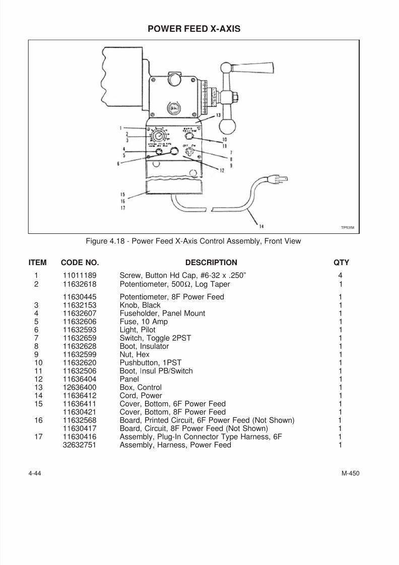
7/28/2019 FullManual Manual Bridgeport
http://slidepdf.com/reader/full/fullmanual-manual-bridgeport 106/134
POWER FEED X-AXIS
ITEM CODE NO. DESCRIPTION QTY
1 11011189 Screw, Button Hd Cap, #6-32 x .250” 42 11632618 Potentiometer, 500Ω, Log Taper 1
11630445 Potentiometer, 8F Power Feed 13 11632153 Knob, Black 14 11632607 Fuseholder, Panel Mount 15 11632606 Fuse, 10 Amp 16 11632593 Light, Pilot 17 11632659 Switch, Toggle 2PST 18 11632628 Boot, Insulator 19 11632599 Nut, Hex 110 11632620 Pushbutton, 1PST 111 11632506 Boot, Insul PB/Switch 112 11636404 Panel 1
13 12636400 Box, Control 114 11636412 Cord, Power 115 11636411 Cover, Bottom, 6F Power Feed 1
11630421 Cover, Bottom, 8F Power Feed 116 11632568 Board, Printed Circuit, 6F Power Feed (Not Shown) 1
11630417 Board, Circuit, 8F Power Feed (Not Shown) 117 11630416 Assembly, Plug-In Connector Type Harness, 6F 1
32632751 Assembly, Harness, Power Feed 1
4-44 M-450
Figure 4.18 - Power Feed X-Axis Control Assembly, Front View
TP5356
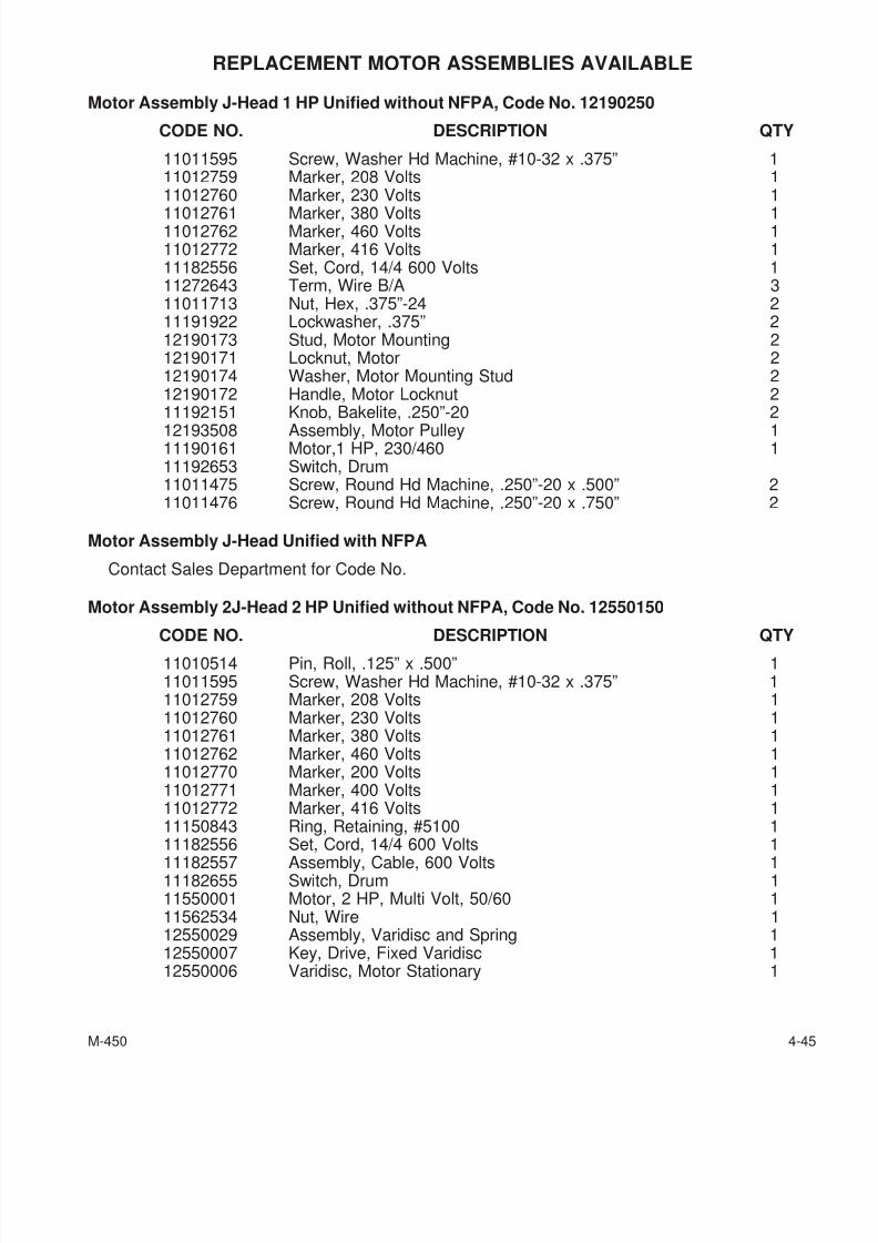
7/28/2019 FullManual Manual Bridgeport
http://slidepdf.com/reader/full/fullmanual-manual-bridgeport 107/134
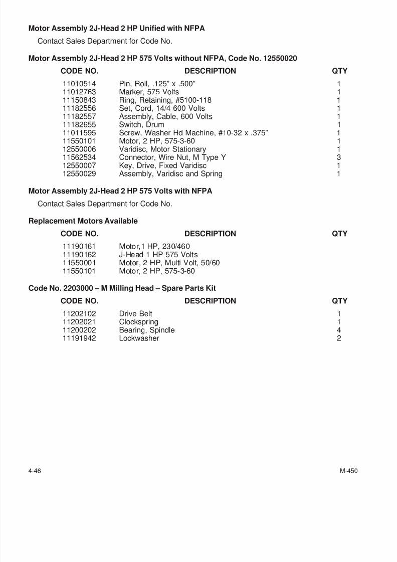
7/28/2019 FullManual Manual Bridgeport
http://slidepdf.com/reader/full/fullmanual-manual-bridgeport 108/134
Motor Assembly 2J-Head 2 HP Unified with NFPA
Contact Sales Department for Code No.
Motor Assembly 2J-Head 2 HP 575 Volts without NFPA, Code No. 12550020
CODE NO. DESCRIPTION QTY
11010514 Pin, Roll, .125” x .500” 111012763 Marker, 575 Volts 111150843 Ring, Retaining, #5100-118 111182556 Set, Cord, 14/4 600 Volts 111182557 Assembly, Cable, 600 Volts 111182655 Switch, Drum 111011595 Screw, Washer Hd Machine, #10-32 x .375” 111550101 Motor, 2 HP, 575-3-60 112550006 Varidisc, Motor Stationary 111562534 Connector, Wire Nut, M Type Y 312550007 Key, Drive, Fixed Varidisc 112550029 Assembly, Varidisc and Spring 1
Motor Assembly 2J-Head 2 HP 575 Volts with NFPAContact Sales Department for Code No.
Replacement Motors Available
CODE NO. DESCRIPTION QTY
11190161 Motor,1 HP, 230/46011190162 J-Head 1 HP 575 Volts11550001 Motor, 2 HP, Multi Volt, 50/6011550101 Motor, 2 HP, 575-3-60
Code No. 2203000 – M Milling Head – Spare Parts KitCODE NO. DESCRIPTION QTY
11202102 Drive Belt 111202021 Clockspring 111200202 Bearing, Spindle 411191942 Lockwasher 2
4-46 M-450
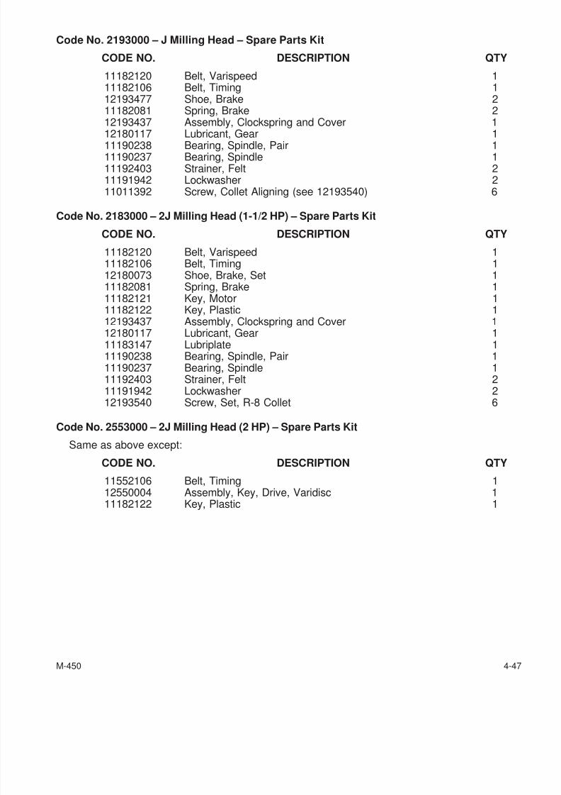
7/28/2019 FullManual Manual Bridgeport
http://slidepdf.com/reader/full/fullmanual-manual-bridgeport 109/134
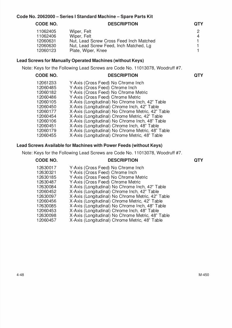
7/28/2019 FullManual Manual Bridgeport
http://slidepdf.com/reader/full/fullmanual-manual-bridgeport 110/134
Code No. 2062000 – Series I Standard Machine – Spare Parts Kit
CODE NO. DESCRIPTION QTY
11062405 Wiper, Felt 211062406 Wiper, Felt 412060631 Nut, Lead Screw Cross Feed Inch Matched 112060630 Nut, Lead Screw Feed, Inch Matched, Lg 112060123 Plate, Wiper, Knee 1
Lead Screws for Manually Operated Machines (without Keys)
Note: Keys for the Following Lead Screws are Code No. 11013078, Woodruff #7.
CODE NO. DESCRIPTION QTY
12061233 Y-Axis (Cross Feed) No Chrome Inch12060485 Y-Axis (Cross Feed) Chrome Inch12060182 Y-Axis (Cross Feed) No Chrome Metric12060486 Y-Axis (Cross Feed) Chrome Metric12060105 X-Axis (Longitudinal) No Chrome Inch, 42” Table12060450 X-Axis (Longitudinal) Chrome Inch, 42” Table
12060177 X-Axis (Longitudinal) No Chrome Metric, 42” Table12060454 X-Axis (Longitudinal) Chrome Metric, 42” Table12060106 X-Axis (Longitudinal) No Chrome Inch, 48” Table12060451 X-Axis (Longitudinal) Chrome Inch, 48” Table12060179 X-Axis (Longitudinal) No Chrome Metric, 48” Table12060455 X-Axis (Longitudinal) Chrome Metric, 48” Table
Lead Screws Available for Machines with Power Feeds (without Keys)
Note: Keys for the Following Lead Screws are Code No. 11013078, Woodruff #7.
CODE NO. DESCRIPTION QTY
12630017 Y-Axis (Cross Feed) No Chrome Inch12630321 Y-Axis (Cross Feed) Chrome Inch12630185 Y-Axis (Cross Feed) No Chrome Metric12630487 Y-Axis (Cross Feed) Chrome Metric12630084 X-Axis (Longitudinal) No Chrome Inch, 42” Table12060452 X-Axis (Longitudinal) Chrome Inch, 42” Table12630097 X-Axis (Longitudinal) No Chrome Metric, 42” Table12060456 X-Axis (Longitudinal) Chrome Metric, 42” Table12630085 X-Axis (Longitudinal) No Chrome Inch, 48” Table12060453 X-Axis (Longitudinal) Chrome Inch, 48” Table12630098 X-Axis (Longitudinal) No Chrome Metric, 48” Table12060457 X-Axis (Longitudinal) Chrome Metric, 48” Table
4-48 M-450
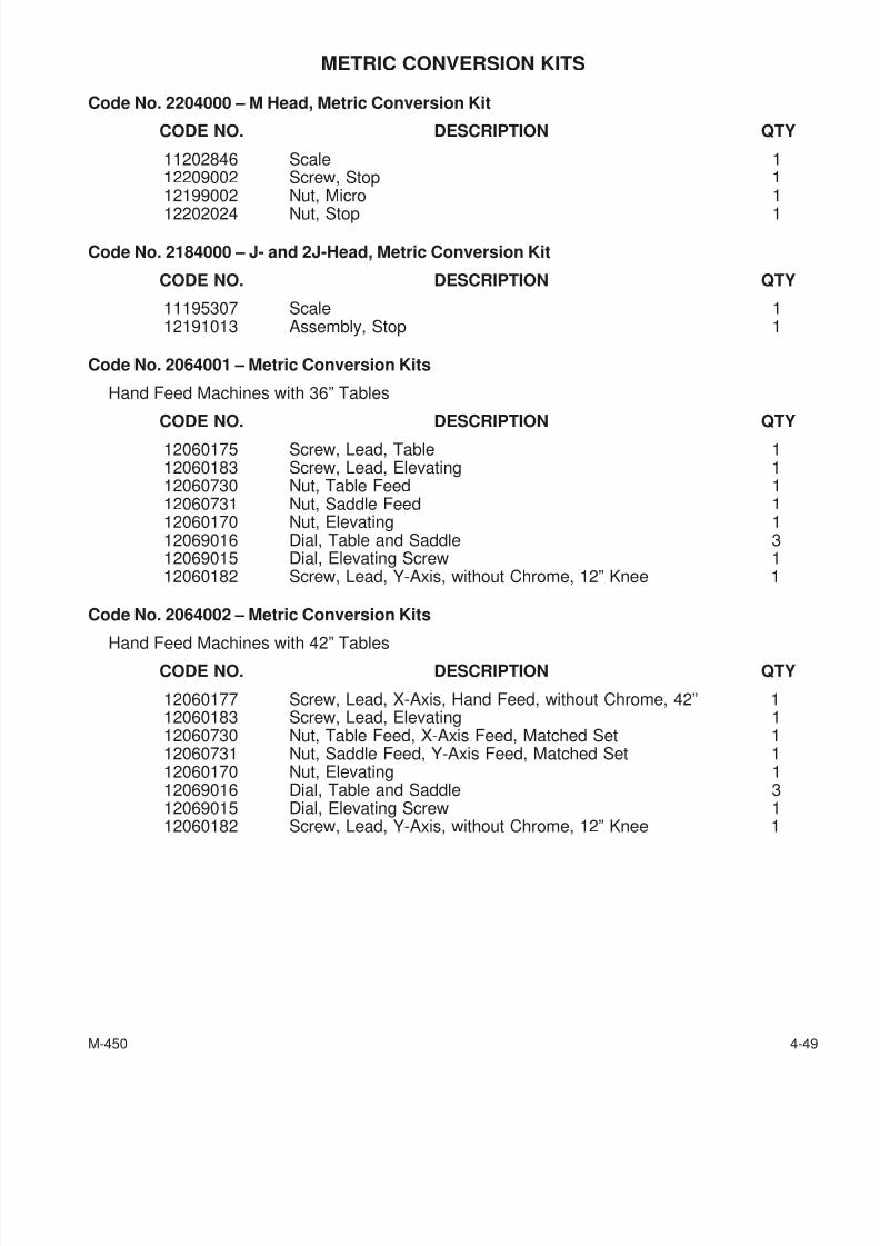
7/28/2019 FullManual Manual Bridgeport
http://slidepdf.com/reader/full/fullmanual-manual-bridgeport 111/134
METRIC CONVERSION KITS
Code No. 2204000 – M Head, Metric Conversion Kit
CODE NO. DESCRIPTION QTY
11202846 Scale 112209002 Screw, Stop 112199002 Nut, Micro 1
12202024 Nut, Stop 1
Code No. 2184000 – J- and 2J-Head, Metric Conversion Kit
CODE NO. DESCRIPTION QTY
11195307 Scale 112191013 Assembly, Stop 1
Code No. 2064001 – Metric Conversion Kits
Hand Feed Machines with 36” Tables
CODE NO. DESCRIPTION QTY12060175 Screw, Lead, Table 112060183 Screw, Lead, Elevating 112060730 Nut, Table Feed 112060731 Nut, Saddle Feed 112060170 Nut, Elevating 112069016 Dial, Table and Saddle 312069015 Dial, Elevating Screw 112060182 Screw, Lead, Y-Axis, without Chrome, 12” Knee 1
Code No. 2064002 – Metric Conversion Kits
Hand Feed Machines with 42” Tables
CODE NO. DESCRIPTION QTY
12060177 Screw, Lead, X-Axis, Hand Feed, without Chrome, 42” 112060183 Screw, Lead, Elevating 112060730 Nut, Table Feed, X-Axis Feed, Matched Set 112060731 Nut, Saddle Feed, Y-Axis Feed, Matched Set 112060170 Nut, Elevating 112069016 Dial, Table and Saddle 312069015 Dial, Elevating Screw 112060182 Screw, Lead, Y-Axis, without Chrome, 12” Knee 1
M-450 4-49
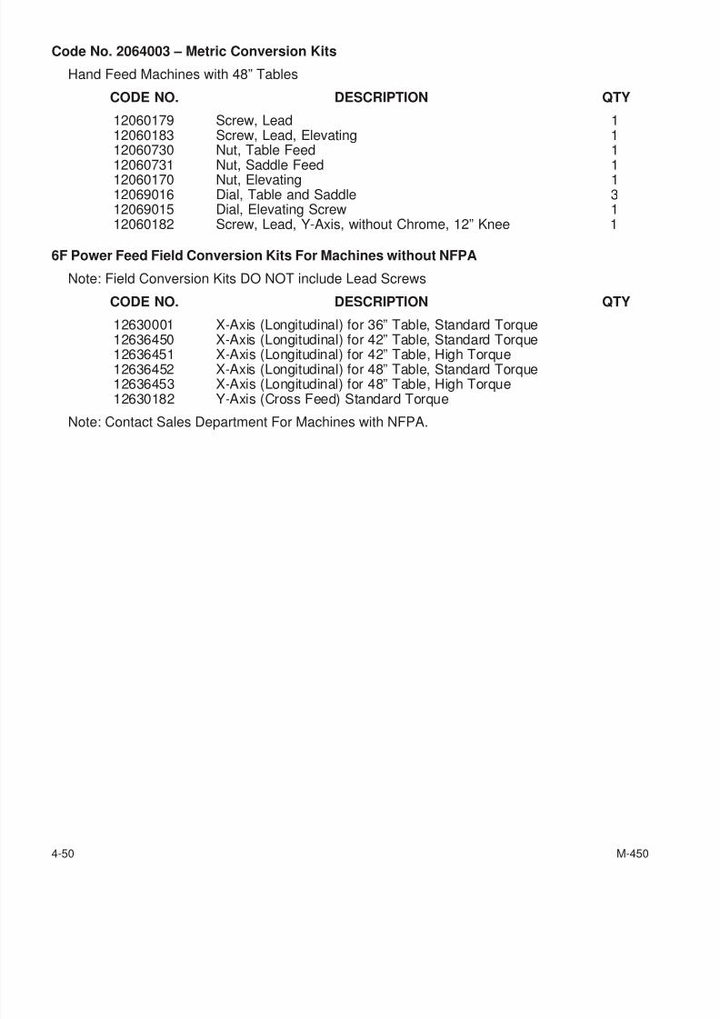
7/28/2019 FullManual Manual Bridgeport
http://slidepdf.com/reader/full/fullmanual-manual-bridgeport 112/134
Code No. 2064003 – Metric Conversion Kits
Hand Feed Machines with 48” Tables
CODE NO. DESCRIPTION QTY
12060179 Screw, Lead 112060183 Screw, Lead, Elevating 112060730 Nut, Table Feed 112060731 Nut, Saddle Feed 112060170 Nut, Elevating 112069016 Dial, Table and Saddle 312069015 Dial, Elevating Screw 112060182 Screw, Lead, Y-Axis, without Chrome, 12” Knee 1
6F Power Feed Field Conversion Kits For Machines without NFPA
Note: Field Conversion Kits DO NOT include Lead Screws
CODE NO. DESCRIPTION QTY
12630001 X-Axis (Longitudinal) for 36” Table, Standard Torque12636450 X-Axis (Longitudinal) for 42” Table, Standard Torque12636451 X-Axis (Longitudinal) for 42” Table, High Torque12636452 X-Axis (Longitudinal) for 48” Table, Standard Torque12636453 X-Axis (Longitudinal) for 48” Table, High Torque12630182 Y-Axis (Cross Feed) Standard Torque
Note: Contact Sales Department For Machines with NFPA.
4-50 M-450

7/28/2019 FullManual Manual Bridgeport
http://slidepdf.com/reader/full/fullmanual-manual-bridgeport 113/134
- NOTES -
M-450 4-51

7/28/2019 FullManual Manual Bridgeport
http://slidepdf.com/reader/full/fullmanual-manual-bridgeport 114/134
- NOTES -
4-52 M-450
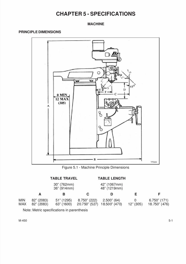
7/28/2019 FullManual Manual Bridgeport
http://slidepdf.com/reader/full/fullmanual-manual-bridgeport 115/134
CHAPTER 5 - SPECIFICATIONS
MACHINE
PRINCIPLE DIMENSIONS
TABLE TRAVEL TABLE LENGTH
30” (762mm) 42” (1067mm)36” (914mm) 48” (1219mm)
A B C D E F
MIN 82” (2083) 51” (1295) 8.750” (222) 2.500” (64) 0 6.750” (171)MAX 82” (2083) 63” (1600) 20.750” (527) 18.500” (470) 12” (305) 18.750” (476)
Note: Metric specifications in parenthesis
M-450 5-1
Figure 5.1 - Machine Principle Dimensions
TP5264
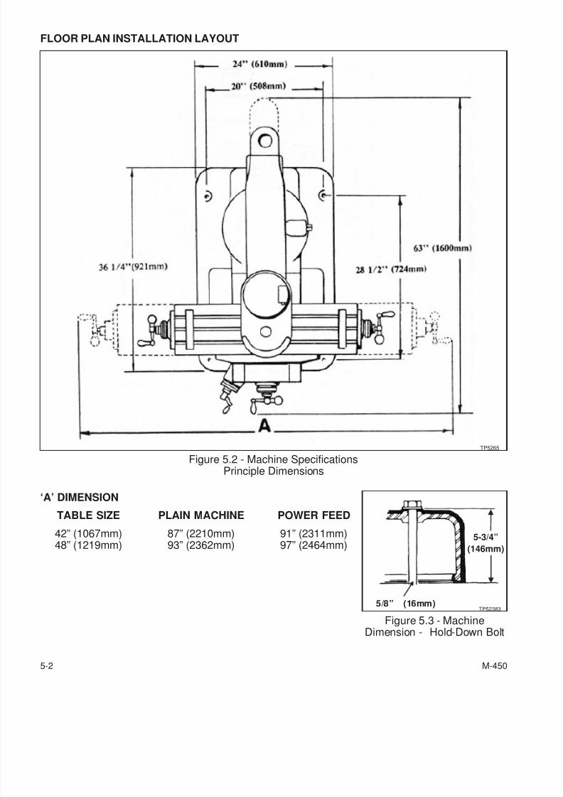
7/28/2019 FullManual Manual Bridgeport
http://slidepdf.com/reader/full/fullmanual-manual-bridgeport 116/134
FLOOR PLAN INSTALLATION LAYOUT
‘A’ DIMENSION
TABLE SIZE PLAIN MACHINE POWER FEED
42” (1067mm) 87” (2210mm) 91” (2311mm)
48” (1219mm) 93” (2362mm) 97” (2464mm)
5-2 M-450
Figure 5.2 - Machine SpecificationsPrinciple Dimensions
TP5265
Figure 5.3 - MachineDimension - Hold-Down Bolt
TP52383
5-3/4”
(146mm)
5/8” (16mm)
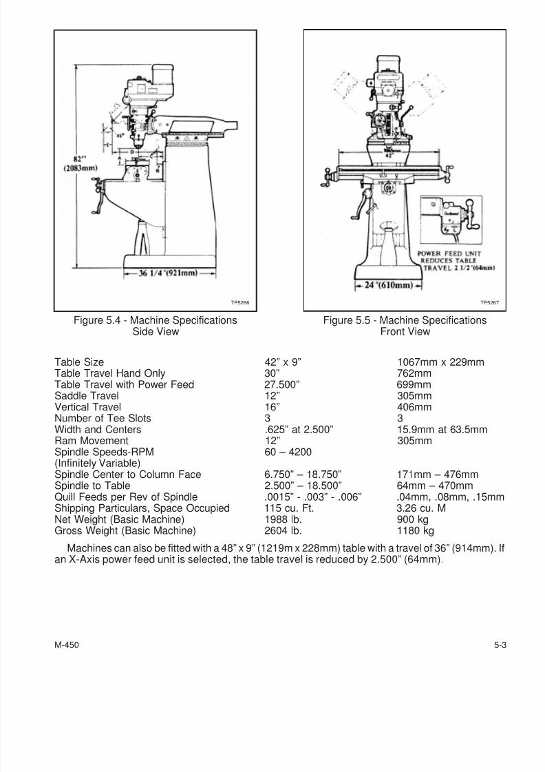
7/28/2019 FullManual Manual Bridgeport
http://slidepdf.com/reader/full/fullmanual-manual-bridgeport 117/134
Table Size 42” x 9” 1067mm x 229mmTable Travel Hand Only 30” 762mmTable Travel with Power Feed 27.500” 699mm
Saddle Travel 12” 305mmVertical Travel 16” 406mmNumber of Tee Slots 3 3Width and Centers .625” at 2.500” 15.9mm at 63.5mmRam Movement 12” 305mmSpindle Speeds-RPM 60 – 4200(Infinitely Variable)Spindle Center to Column Face 6.750” – 18.750” 171mm – 476mmSpindle to Table 2.500” – 18.500” 64mm – 470mmQuill Feeds per Rev of Spindle .0015” - .003” - .006” .04mm, .08mm, .15mmShipping Particulars, Space Occupied 115 cu. Ft. 3.26 cu. MNet Weight (Basic Machine) 1988 lb. 900 kg
Gross Weight (Basic Machine) 2604 lb. 1180 kg
Machines can also be fitted with a 48” x 9” (1219m x 228mm) table with a travel of 36” (914mm). Ifan X-Axis power feed unit is selected, the table travel is reduced by 2.500” (64mm).
M-450 5-3
Figure 5.4 - Machine SpecificationsSide View
TP5266
Figure 5.5 - Machine SpecificationsFront View
TP5267
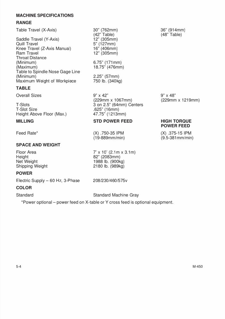
7/28/2019 FullManual Manual Bridgeport
http://slidepdf.com/reader/full/fullmanual-manual-bridgeport 118/134
MACHINE SPECIFICATIONS
RANGE
Table Travel (X-Axis) 30” (762mm) 36” (914mm)(42” Table) (48” Table)
Saddle Travel (Y-Axis) 12” (305mm)Quill Travel 5” (127mm)Knee Travel (Z-Axis Manual) 16” (406mm)
Ram Travel 12” (305mm)Throat Distance(Minimum) 6.75” (171mm)(Maximum) 18.75” (476mm)Table to Spindle Nose Gage Line(Minimum) 2.25” (57mm)Maximum Weight of Workpiece 750 lb. (340kg)
TABLE
Overall Sizes 9” x 42” 9” x 48”(229mm x 1067mm) (229mm x 1219mm)
T-Slots 3 on 2.5” (64mm) Centers
T-Slot Size .625” (16mm)Height Above Floor (Max.) 47.75” (1213mm)
MILLING STD POWER FEED HIGH TORQUEPOWER FEED
Feed Rate* (X) .750-35 IPM (X) .375-15 IPM(19-889mm/min) (9.5-381mm/min)
SPACE AND WEIGHT
Floor Area 7’ x 10’ (2.1m x 3.1m)Height 82” (2083mm)Net Weight 1988 lb. (900kg)Shipping Weight 2180 lb. (989kg)
POWER
Electric Supply – 60 Hz, 3-Phase 208/230/460/575v
COLOR
Standard Standard Machine Gray
*Power optional – power feed on X-table or Y cross feed is optional equipment.
5-4 M-450
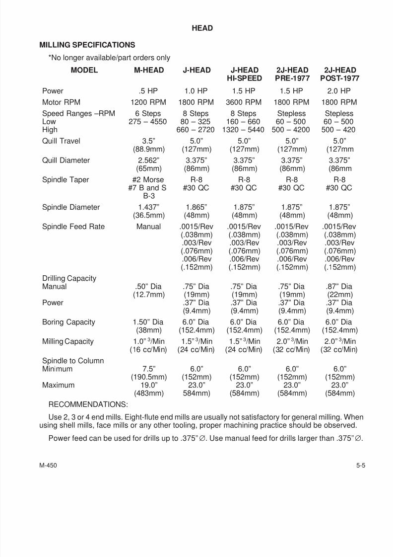
7/28/2019 FullManual Manual Bridgeport
http://slidepdf.com/reader/full/fullmanual-manual-bridgeport 119/134
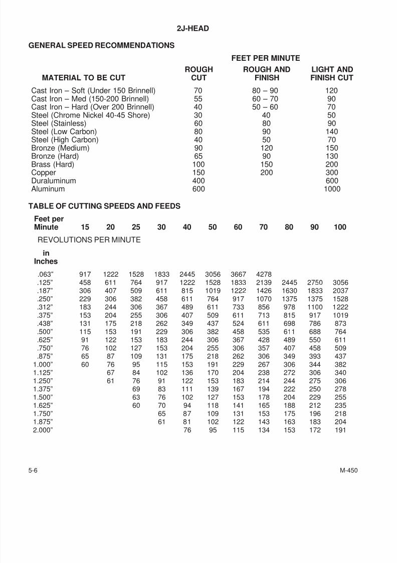
7/28/2019 FullManual Manual Bridgeport
http://slidepdf.com/reader/full/fullmanual-manual-bridgeport 120/134
2J-HEAD
GENERAL SPEED RECOMMENDATIONS
FEET PER MINUTE
ROUGH ROUGH AND LIGHT ANDMATERIAL TO BE CUT CUT FINISH FINISH CUT
Cast Iron – Soft (Under 150 Brinnell) 70 80 – 90 120Cast Iron – Med (150-200 Brinnell) 55 60 – 70 90Cast Iron – Hard (Over 200 Brinnell) 40 50 – 60 70Steel (Chrome Nickel 40-45 Shore) 30 40 50Steel (Stainless) 60 80 90Steel (Low Carbon) 80 90 140Steel (High Carbon) 40 50 70Bronze (Medium) 90 120 150Bronze (Hard) 65 90 130Brass (Hard) 100 150 200Copper 150 200 300Duraluminum 400 600Aluminum 600 1000
TABLE OF CUTTING SPEEDS AND FEEDS
Feet perMinute 15 20 25 30 40 50 60 70 80 90 100
REVOLUTIONS PER MINUTE
inInches
.063” 917 1222 1528 1833 2445 3056 3667 4278.125” 458 611 764 917 1222 1528 1833 2139 2445 2750 3056
.187” 306 407 509 611 815 1019 1222 1426 1630 1833 2037
.250” 229 306 382 458 611 764 917 1070 1375 1375 1528
.312” 183 244 306 367 489 611 733 856 978 1100 1222
.375” 153 204 255 306 407 509 611 713 815 917 1019
.438” 131 175 218 262 349 437 524 611 698 786 873
.500” 115 153 191 229 306 382 458 535 611 688 764
.625” 91 122 153 183 244 306 367 428 489 550 611
.750” 76 102 127 153 204 255 306 357 407 458 509
.875” 65 87 109 131 175 218 262 306 349 393 4371.000” 60 76 95 115 153 191 229 267 306 344 3821.125” 67 84 102 136 170 204 238 272 306 3401.250” 61 76 91 122 153 183 214 244 275 3061.375” 69 83 111 139 167 194 222 250 2781.500” 63 76 102 127 153 178 204 229 2551.625” 60 70 94 118 141 165 188 212 2351.750” 65 87 109 131 153 175 196 2181.875” 61 81 102 122 143 163 183 2042.000” 76 95 115 134 153 172 191
5-6 M-450
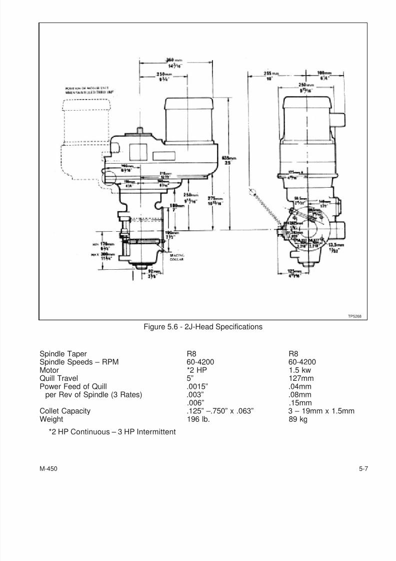
7/28/2019 FullManual Manual Bridgeport
http://slidepdf.com/reader/full/fullmanual-manual-bridgeport 121/134
Spindle Taper R8 R8Spindle Speeds – RPM 60-4200 60-4200Motor *2 HP 1.5 kwQuill Travel 5” 127mm
Power Feed of Quill .0015” .04mmper Rev of Spindle (3 Rates) .003” .08mm
.006” .15mmCollet Capacity .125” –.750” x .063” 3 – 19mm x 1.5mmWeight 196 lb. 89 kg
*2 HP Continuous – 3 HP Intermittent
M-450 5-7
Figure 5.6 - 2J-Head Specifications
TP5268
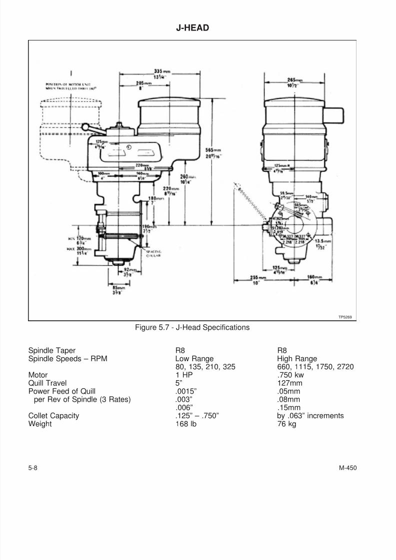
7/28/2019 FullManual Manual Bridgeport
http://slidepdf.com/reader/full/fullmanual-manual-bridgeport 122/134
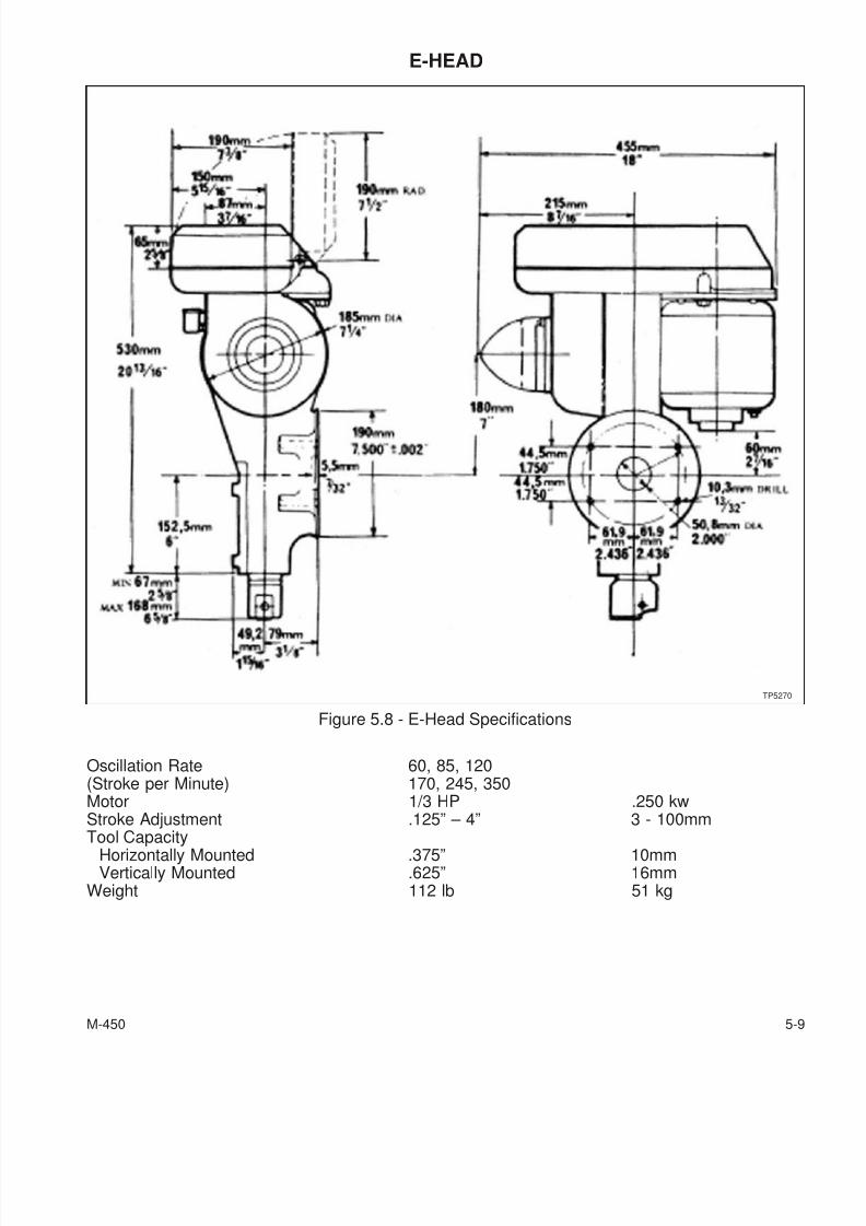
7/28/2019 FullManual Manual Bridgeport
http://slidepdf.com/reader/full/fullmanual-manual-bridgeport 123/134
E-HEAD
Oscillation Rate 60, 85, 120(Stroke per Minute) 170, 245, 350Motor 1/3 HP .250 kwStroke Adjustment .125” – 4” 3 - 100mm
Tool CapacityHorizontally Mounted .375” 10mmVertically Mounted .625” 16mm
Weight 112 lb 51 kg
M-450 5-9
Figure 5.8 - E-Head Specifications
TP5270
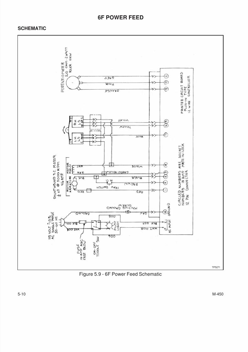
7/28/2019 FullManual Manual Bridgeport
http://slidepdf.com/reader/full/fullmanual-manual-bridgeport 124/134
6F POWER FEED
SCHEMATIC
5-10 M-450
Figure 5.9 - 6F Power Feed Schematic
TP5271
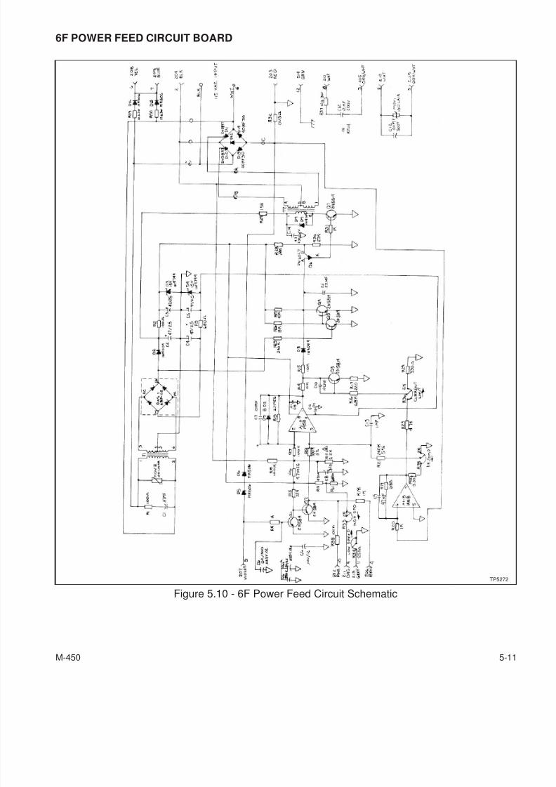
7/28/2019 FullManual Manual Bridgeport
http://slidepdf.com/reader/full/fullmanual-manual-bridgeport 125/134
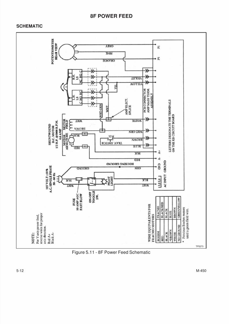
7/28/2019 FullManual Manual Bridgeport
http://slidepdf.com/reader/full/fullmanual-manual-bridgeport 126/134
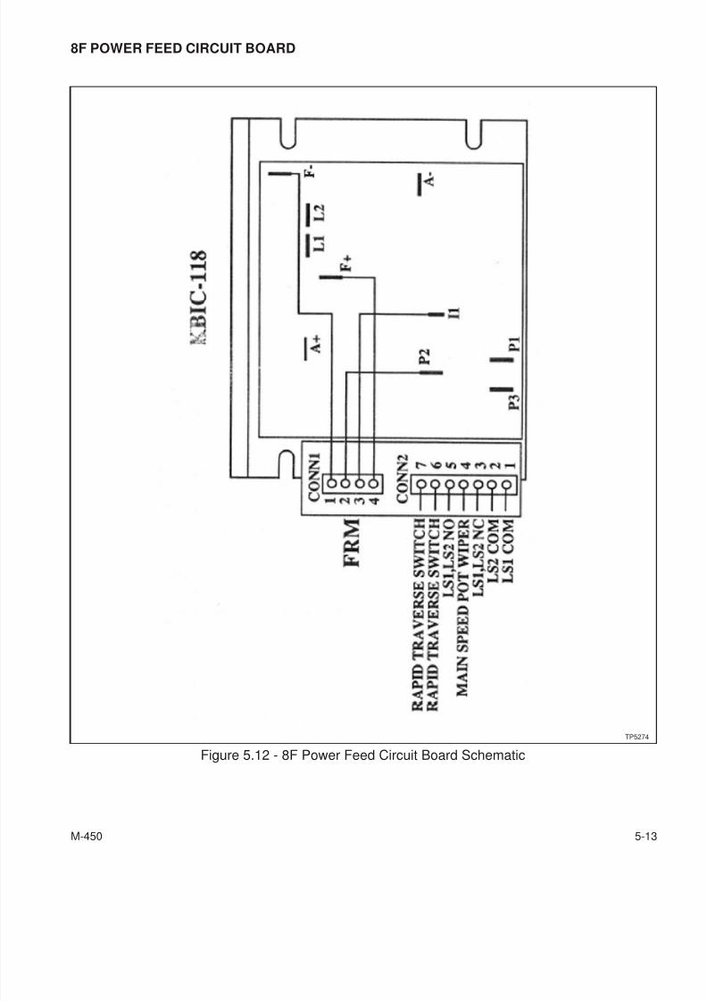
7/28/2019 FullManual Manual Bridgeport
http://slidepdf.com/reader/full/fullmanual-manual-bridgeport 127/134
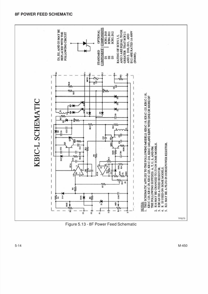
7/28/2019 FullManual Manual Bridgeport
http://slidepdf.com/reader/full/fullmanual-manual-bridgeport 128/134
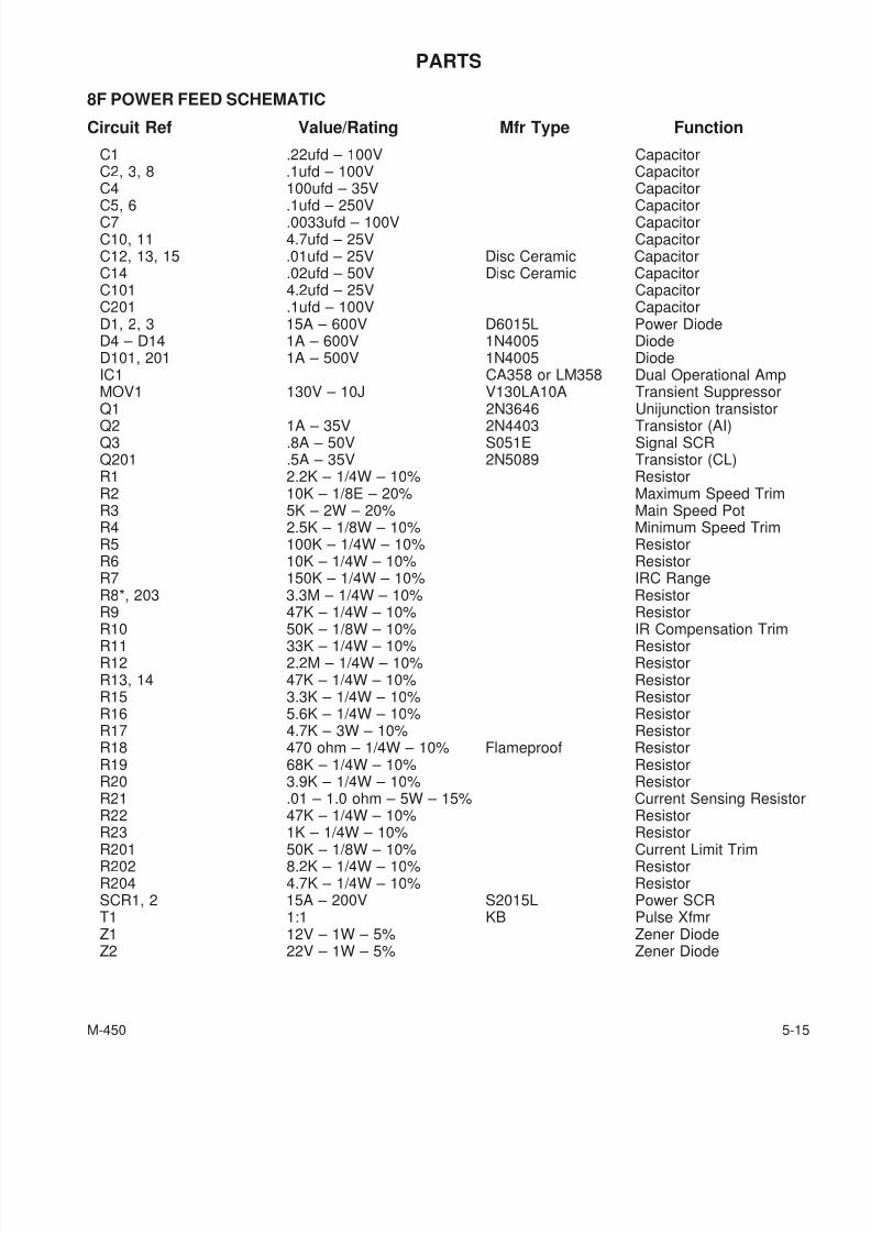
7/28/2019 FullManual Manual Bridgeport
http://slidepdf.com/reader/full/fullmanual-manual-bridgeport 129/134
PARTS
8F POWER FEED SCHEMATIC
Circuit Ref Value/Rating Mfr Type Function
C1 .22ufd – 100V CapacitorC2, 3, 8 .1ufd – 100V CapacitorC4 100ufd – 35V Capacitor
C5, 6 .1ufd – 250V CapacitorC7 .0033ufd – 100V CapacitorC10, 11 4.7ufd – 25V CapacitorC12, 13, 15 .01ufd – 25V Disc Ceramic CapacitorC14 .02ufd – 50V Disc Ceramic CapacitorC101 4.2ufd – 25V CapacitorC201 .1ufd – 100V CapacitorD1, 2, 3 15A – 600V D6015L Power DiodeD4 – D14 1A – 600V 1N4005 DiodeD101, 201 1A – 500V 1N4005 DiodeIC1 CA358 or LM358 Dual Operational AmpMOV1 130V – 10J V130LA10A Transient SuppressorQ1 2N3646 Unijunction transistor
Q2 1A – 35V 2N4403 Transistor (AI)Q3 .8A – 50V S051E Signal SCRQ201 .5A – 35V 2N5089 Transistor (CL)R1 2.2K – 1/4W – 10% ResistorR2 10K – 1/8E – 20% Maximum Speed TrimR3 5K – 2W – 20% Main Speed PotR4 2.5K – 1/8W – 10% Minimum Speed TrimR5 100K – 1/4W – 10% ResistorR6 10K – 1/4W – 10% ResistorR7 150K – 1/4W – 10% IRC RangeR8*, 203 3.3M – 1/4W – 10% ResistorR9 47K – 1/4W – 10% Resistor
R10 50K – 1/8W – 10% IR Compensation TrimR11 33K – 1/4W – 10% ResistorR12 2.2M – 1/4W – 10% ResistorR13, 14 47K – 1/4W – 10% ResistorR15 3.3K – 1/4W – 10% ResistorR16 5.6K – 1/4W – 10% ResistorR17 4.7K – 3W – 10% ResistorR18 470 ohm – 1/4W – 10% Flameproof ResistorR19 68K – 1/4W – 10% ResistorR20 3.9K – 1/4W – 10% ResistorR21 .01 – 1.0 ohm – 5W – 15% Current Sensing ResistorR22 47K – 1/4W – 10% ResistorR23 1K – 1/4W – 10% Resistor
R201 50K – 1/8W – 10% Current Limit TrimR202 8.2K – 1/4W – 10% ResistorR204 4.7K – 1/4W – 10% ResistorSCR1, 2 15A – 200V S2015L Power SCRT1 1:1 KB Pulse XfmrZ1 12V – 1W – 5% Zener DiodeZ2 22V – 1W – 5% Zener Diode
M-450 5-15
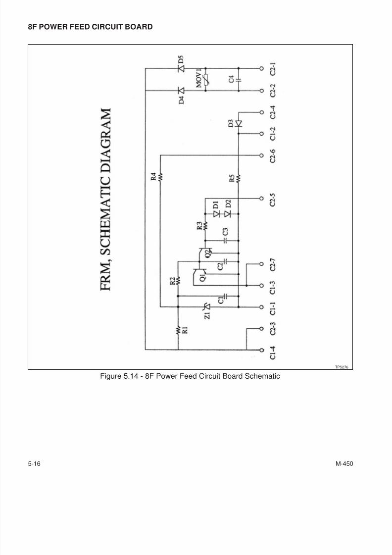
7/28/2019 FullManual Manual Bridgeport
http://slidepdf.com/reader/full/fullmanual-manual-bridgeport 130/134
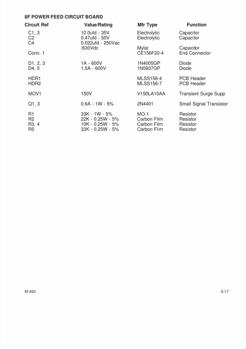
7/28/2019 FullManual Manual Bridgeport
http://slidepdf.com/reader/full/fullmanual-manual-bridgeport 131/134
8F POWER FEED CIRCUIT BOARD
Circuit Ref Value/Rating Mfr Type Function
C1, 3 10.0ufd - 35V Electrolytic CapacitorC2 0.47ufd - 50V Electrolytic CapacitorC4 0.022ufd - 250Vac
/630Vdc Mylar CapacitorConn. 1 CE156F20-4 End Connector
D1, 2, 3 1A - 600V 1N4005GP DiodeD4, 5 1.5A - 600V 1N5937GP Diode
HDR1 MLSS156-4 PCB HeaderHDR2 MLSS156-7 PCB Header
MOV1 150V V150LA10AA Transient Surge Supp
Q1, 3 0.6A - 1W - 5% 2N4401 Small Signal Transistor
R1 33K - 1W - 5% MO-1 Resistor
R2 22K - 0.25W - 5% Carbon Film ResistorR3, 4 10K - 0.25W - 5% Carbon Film ResistorR5 33K - 0.25W - 5% Carbon Film Resistor
M-450 5-17

7/28/2019 FullManual Manual Bridgeport
http://slidepdf.com/reader/full/fullmanual-manual-bridgeport 132/134
- NOTES -
5-18 M-450

7/28/2019 FullManual Manual Bridgeport
http://slidepdf.com/reader/full/fullmanual-manual-bridgeport 133/134

7/28/2019 FullManual Manual Bridgeport
http://slidepdf.com/reader/full/fullmanual-manual-bridgeport 134/134
Recommended

![igor.chudov.comigor.chudov.com/projects/Bridgeport-Series-II... · EMC V2.4 Integrator Manual CONTENTS 4.2.1 [EMC] Section. . . . . . . . . . . . . . . . . . . . . . . . . . . .](https://img.pdfslide.net/doc/110x75/5f0e25277e708231d43dd3e1/igor-emc-v24-integrator-manual-contents-421-emc-section-.jpg)