GOVERNMENT OF INDIA
MINISTRY OF RAILWAYS
A TECHNICAL GUIDE ON
DERAILMENTS
CAMTECH/M/3
APRIL 1998
MAHARAJPUR, GWALIOR - 474020
Centre
for
Advanced
Maintenance
Technology
EXCELLENCE IN MAINTEANCE
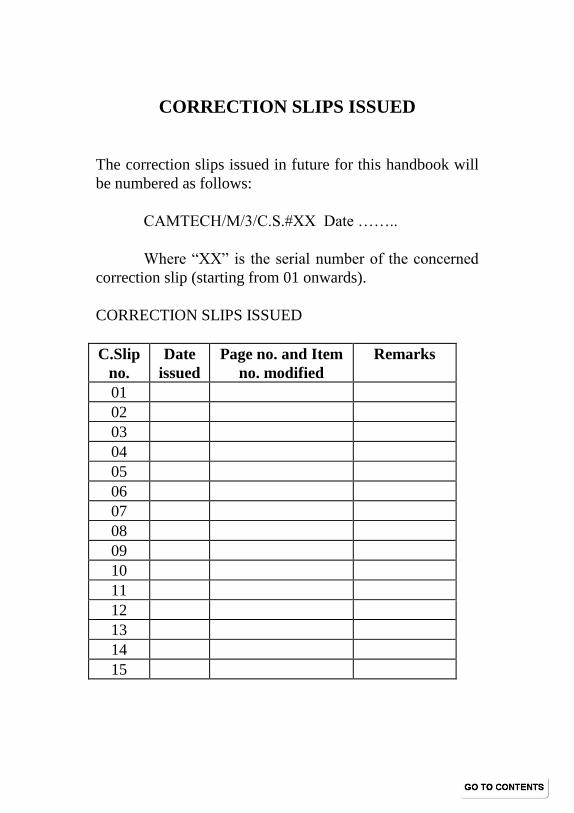
CORRECTION SLIPS ISSUED
The correction slips issued in future for this handbook will
be numbered as follows:
CAMTECH/M/3/C.S.#XX Date ……..
Where “XX” is the serial number of the concerned
correction slip (starting from 01 onwards).
CORRECTION SLIPS ISSUED
C.Slip
no.
Date
issued
Page no. and Item
no. modified
Remarks
01
02
03
04
05
06
07
08
09
10
11
12
13
14
15
PREFACE
Derailments keep presenting newer challenges to Indian
Railways continuously. The causes are numerous and their
investigation results in discovery of newer and better remedial
measures for preventing future derailments. It is in this direction
that Railway Board assigned the task of preparing this guide to
CAMTECH. The objective is to enable the staff and supervisors to
understand the complex and intricate mechanism involved in rail-
wheel interaction and the conditions resulting in derailments. This
will ensure thorough analysis as well as discovery of new ideas for
arresting derailments.
The Guide contains useful hints on good maintenance
practices and explains the correct way of taking critical
measurements with the help of simple sketches and tables. If these
help railways in reducing derailments, the purpose of producing
this Guide will be served.
We are extremely thankful to Shri R.Paranthaman, Retd.
CWS,S.Rly for contributing many valuable ideas and suggestions
during preparation of this Guide. We would also like to recognise
the sincere efforts put in by Shri S.K.Lomash, C.T.A. and Shri
Ulhas Borwankar, DEO during preparation of this book
Gwalior D.K. Saraf
Date : 01.07.98 Director/CAMTECH
CAMTECH/M/3 ix
CONTENTS PREFACE …………….. iii
CORRECTION SLIPS ISSUED ……………. iv
CHAPTER 1 MECHANISM OF DERAILMENT
1.1 INTRODUCTION ………………………............ 1
Definition of Derailment ………………………….. 2
Derailment Investigation……………………………. 3
1.2 DERAILMENT MECHANISM
1.2.1 Sudden derailments ……………………… 5
1.2.2 Gradual Derailments ………………………… 5
1.3 MECHANISM OF WHEEL FLANGE CLIMBING
1.3.1 Angle Of Attack……………………………… 10
1.3.2 Angularity of Axle…………………………… 10
1.3.3 Play Between Wheel and Rail……………… 14
1.4 WHEEL OFF-LOADING ……………………. ............15
1.5 VEHICLE OSCILLATIONS DUE TO RAIL-WHEEL
INTERACTION …………………….........................17
1.5.1 UNEQUAL SPRING CHARACTERISTICS ................ 17
1.5.2 VERTICAL IRREGULARITIES IN TRACK ............... 18
1.5.3 UNEVEN LOADING .................................................. 18
1.5.4 AXLE LOAD VARIATIONS DURING RUN ................. 18
1.5.5 DYNAMIC ASPECTS .................................................. 19
1.6 LATERAL STABILITY OF TRACK ................................ 22
1.7 PRECONDITIONS FOR DERAILMENT ........................ 23
1.8 DERAILMENT ON CURVES .......................................... 24
CHAPTER 2 SITE INVESTIGATION
2.1 FIRST CONSIDERATIONS............................................ 28
2.2 SITE SKETCH .............................................................. 28
2.3 FLANGE MARKS ON THE RAIL ................................... 28
2.4 OPERATIONAL DEFECTS ............................................ 30
CAMTECH/M/3 x
2.4.1 SPEED .................................................................... 30
2.4.2 LOADING ................................................................ 31
2.4.3 WRONG MARSHALLING ....................................... 31
2.4.4 MISMANIPULATION OF POINT ........................... 32
2.4.5 OPERATING STAFF FAILURE ............................. 32
2.4.6 IMPROPER TRAIN OPERATION BY THE
DRIVER ................................................................. 33
2.5 ROLLING STOCK EXAMINATION ................................ 33
2.6 TRACK SURVEY AND EXAMINATION ......................... 33
CHAPTER 3 ROLLING STOCK
3.1 WHEEL GAUGE ............................................................ 34
3.2 BENT AXLE ................................................................... 37
3.3 TYRE PROFILE ............................................................. 37
3.4 WHEEL DEFECTS ........................................................ 38
3.4.1 THIN FLANGE ......................................................... 39
3.4.2 SHARP FLANGE ..................................................... 40
3.4.3 WORN OUT FLANGE ............................................. 40
3.4.4 DEEP FLANGE ....................................................... 41
3.4.5 FALSE FLANGE/HOLLOW TYRE .......................... 42
3.4.6 FLAT PLACES ON TYRE ....................................... 43
3.4.7 DIFFERENCE OF WHEEL DIAMETER ON
TREAD .................................................................. 44
3.5 AXLE BOX LATERAL AND LONGITUDINAL
CLEARANCES ........................................................... 46
3.6 BUFFING GEAR ........................................................... 47
3.6.1 BUFFER PROJECTION LIMITS FROM HEAD
STOCK .................................................................. 47
3.6.2 DISPLACED BUFFER............................................. 48
3.7 SPRING AND SPRING GEAR ....................................... 48
CAMTECH/M/3 xi
3.7.1 DEFECTS AFFECTING THE FUNCTIONING OF
SPRINGS .............................................................. 49
3.7.2 VARIATION IN PERFORMANCE OF DIFFERENT
SPRINGS ON THE SAME VEHICLE .................... 49
3.7.3 FAILURE OF SPRINGS .......................................... 51
CHAPTER 4 PERMANENT WAY
4.1 FORMATION ................................................................. 52
4.2 BALLAST ....................................................................... 54
4.2.1 TYPES OF BALLAST ............................................. 54
4.2.2 BALLAST RESISTANCE ....................................... 56
4.3 SLEEPERS AND FASTENINGS ................................. 56
4.4 RAILS ........................................................................... 58
4.4.1 VERTICAL WEAR ................................................... 58
4.4.2 LATERAL WEAR .................................................... 59
4.5 GAUGE ......................................................................... 61
4.5.1 EFFECT OF TIGHT OR SLACK GAUGE ............. 61
4.5.2 TIGHT GAUGE ........................................................ 61
4.5.3 CAUSES OF GAUGE DISTORTION ....................... 62
4.5.4 MARKING STATIONS FOR TRACK
MEASUREMENTS ................................................ 62
4.5.5 HOW TO MEASURE GAUGE ................................. 63
4.5.6 PERMISSIBLE GAUGE TOLERANCES ................. 64
4.6 CROSS LEVEL .............................................................. 65
4.6.1 Effect of Variation in Cross Levels .................. 65
4.6.2 How to Measure Cross Levels ......................... 66
4.7 TWIST ............................................................................ 67
4.7.1 EFFECT OF TWIST................................................. 68
4.7.2 CALCULATING EFFECTIVE TWIST ...................... 68
4.7.3 PERMISSIBLE STANDARDS FOR TWIST ............ 69
4.8 TRACK ALIGNMENT AND UNEVENNESS .................. 69
4.9 CREEP ........................................................................... 70
CAMTECH/M/3 xii
4.9.1 Causes of Creep ................................................. 70
4.9.2 Effect of creep .................................................. 72
4.9.3 Measurement Of Creep .................................... 74
4.9.4 Remedial Steps against Creep ......................... 74
4.9.5 Track Maintenance against Excessive Creep . 75
4.9.6 Track Lengths susceptible to Creep ............... 76
4.10 BUCKLING OF TRACK .............................................. 76
4.10.1 CONDITIONS INDUCING BUCKLING ................ 77
4.10.2 PRECAUTION AGAINST BUCKLING ................ 77
CHAPTER 5 DERAILMENT ON CURVES
5.1 ADVERSE FACTORS ON A CURVE ............................ 79
5.2 CANT OR SUPERELEVATION ..................................... 80
5.2.1 REASONS FOR PROVIDING
SUPERELEVATION ............................................... 81
5.2.2 DEGREE OF CURVE VS RADIUS OF CURVE .... 82
5.2.3 EFFECT OF EXCESSIVE OR INADEQUATE
CANT ...................................................................... 82
5.3 CANT DEFICIENCY ....................................................... 83
5.4 TRANSITION CURVE .................................................... 85
5.4.1 LENGTH OF TRANSITION CURVE ........................ 86
5.5 VERSINE ....................................................................... 87
5.5.1 OBJECTIVE OF MEASURING VERSINE ............... 87
5.5.2 HOW TO MEASURE VERSINE .............................. 88
5.5.3 TO DETERMINE THE DEGREE OF CURVE
WITH THE HELP OF VERSINE ............................. 88
CHAPTER 6 POINTS AND CROSINGS
6.1 SWITCH ASSEMBLY .................................................... 89
6.2 CROSSING ASSEMBLY ............................................... 90
6.3 IMPORTANT ASPECTS IN POINTS AND CROSSING
MAINTENANCE ........................................................... 91
6.4 DERAILMENTS ON POINTS AND CROSSINGS ......... 94
CAMTECH/M/3 xiii
APPENDIX „A‟
PROFORMA TO BE FILLED UP IN CASE OF
DERAILMENT ........................................................... 99
APPENDIX „B‟
STANDARD DIMENSION OF PERMANENT WAY . 113
APPENDIX „C‟
CALCULATION OF GAUGE SLACKNESS WHICH
MAY CAUSE DERAILMENTS................................. 115
APPENDIX „D‟
EXTRACT FROM INDIAN RAILWAYS
PERMANENT WAY MANUAL (1986) CHAPTER
VII ............................................................................ 116
APPENDIX „E‟
Excerpts from “FRENCH RAILWAY
TECHNIQUES”………..……………………..122
GLOSSARY ....................................................................... 124
BIBLIOGRAPHY ................................................................ 128
INDEX …………… ……… …… …… ........................ 130
CAMTECH/M/3
A TECHNICAL GUIDE ON DERAILMENTS April ‘98
CHAPTER 1
MECHANISM OF DERAILMENT
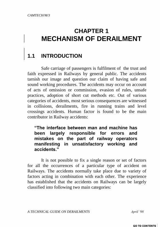
1.1 INTRODUCTION
Safe carriage of passengers is fulfilment of the trust and
faith expressed in Railways by general public. The accidents
tarnish our image and question our claim of having safe and
sound working procedures. The accidents may occur on account
of acts of omission or commission, evasion of rules, unsafe
practices, adoption of short cut methods etc. Out of various
categories of accidents, most serious consequences are witnessed
in collisions, derailments, fire in running trains and level
crossings accidents. Human factor is found to be the main
contributor in Railway accidents:
“The interface between man and machine has
been largely responsible for errors and
mistakes on the part of railway operators
manifesting in unsatisfactory working and
accidents.”
It is not possible to fix a single reason or set of factors
for all the occurrences of a particular type of accident on
Railways. The accidents normally take place due to variety of
factors acting in combination with each other. The experience
has established that the accidents on Railways can be largely
classified into following two main categories:
CAMTECH/M/3
A TECHNICAL GUIDE ON DERAILMENTS April ‘98
2
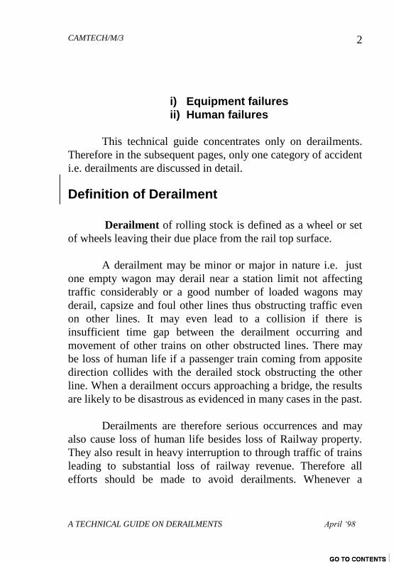
i) Equipment failures
ii) Human failures
This technical guide concentrates only on derailments.
Therefore in the subsequent pages, only one category of accident
i.e. derailments are discussed in detail.
Definition of Derailment
Derailment of rolling stock is defined as a wheel or set
of wheels leaving their due place from the rail top surface.
A derailment may be minor or major in nature i.e. just
one empty wagon may derail near a station limit not affecting
traffic considerably or a good number of loaded wagons may
derail, capsize and foul other lines thus obstructing traffic even
on other lines. It may even lead to a collision if there is
insufficient time gap between the derailment occurring and
movement of other trains on other obstructed lines. There may
be loss of human life if a passenger train coming from apposite
direction collides with the derailed stock obstructing the other
line. When a derailment occurs approaching a bridge, the results
are likely to be disastrous as evidenced in many cases in the past.
Derailments are therefore serious occurrences and may
also cause loss of human life besides loss of Railway property.
They also result in heavy interruption to through traffic of trains
leading to substantial loss of railway revenue. Therefore all
efforts should be made to avoid derailments. Whenever a
CAMTECH/M/3
A TECHNICAL GUIDE ON DERAILMENTS April ‘98
3
derailment occurs, thorough investigation must be carried out to
find out the exact cause and avoid recurrence in future.
Statistics about derailments reveal that the most
prominent causes are: failure of railway staff in properly
examining railway equipment; inadequate maintenance of
locomotives, rolling stock, track, signals etc.; and other
operational irregularities.
Derailment Investigation
The derailments present a burning problem to Railways.
Unless cause is obvious e.g. cattle run over, sudden falling of
boulders, trees etc. on the track, sinking of track, breach or
wash-away etc., it is necessary to thoroughly investigate the role
of track and vehicle in causing the derailment.
While investigating the derailments, track defects,
vehicle defects and other operational features have to be
examined which could have caused:
Flange force Y to increase
Wheel load Q to decrease
Angle of attack to increase
The above factors are explained in detail later in this
chapter under “MECHANISM OF WHEEL FLANGE
CLIMBING”. The list of such contributory defects and operating
features help in analysing and determining the most probable
cause of derailment.
CAMTECH/M/3
A TECHNICAL GUIDE ON DERAILMENTS April ‘98
4
A derailment may be sudden or gradual due to failure of
one or more of the following :
A) Operational factors
B) Track
C) Rolling Stock
D) S & T
E) Others
To investigate these, it is necessary to take a complete set
of measurements and observations and to obtain such back
ground information as may be relevant. Thereafter critically
analyse these factors in a logical sequence. This data and
analysis should enable identification of the first wheel to derail
and the dynamic and quasi-static forces both lateral and vertical
acting on that wheel at the time of derailment. It is also essential
to determine the point of mount/drop.
If the cause is obvious e.g. tree or boulder falling on the
track, breach, wash away, formation failure etc., then
investigation becomes easier. If cause is not obvious then
thorough investigation is required to be made by measuring
various parameters of rolling stock, track etc. in order to
ascertain the exact cause of derailment. The derailments occurs
if a combination of factors act for a long enough period for the
flange to climb the gauge face of the rail and then cross the rail
table. The important theoretical aspects concerning derailments
are:
1. Derailment mechanism
2. Wheel off loading
CAMTECH/M/3
A TECHNICAL GUIDE ON DERAILMENTS April ‘98
5
3. Vehicle oscillation
4. Lateral stability of track
1.2 DERAILMENT MECHANISM
There are two broad categories of derailment:
Sudden derailments - Instant dismounting of wheel
from rail.
Gradual derailments - Gradual climbing of flange
on the rail.
1.2.1 Sudden derailments
When derailing forces are quite high on a wheel, it may
suddenly jump off from the rail table and the rolling stock
derails. In this case, no flange mounting marks are available on
the rail table. However the wheel drop marks can be seen on
ballast or sleepers.
The possible causes for a sudden derailment are:
Sudden shifting of load
Improper loaded vehicle
Excessive speed on curve or turn out
Sudden variation in draw bar forces induced due to improper
train operations(sudden braking or acceleration)
Broken wheels/springs or suspension gear components.
Failure of track or vehicle component
Obstruction on track.
CAMTECH/M/3
A TECHNICAL GUIDE ON DERAILMENTS April ‘98
6
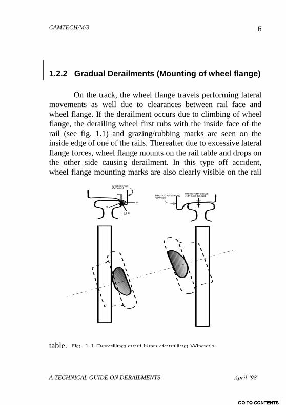
1.2.2 Gradual Derailments (Mounting of wheel flange)
On the track, the wheel flange travels performing lateral
movements as well due to clearances between rail face and
wheel flange. If the derailment occurs due to climbing of wheel
flange, the derailing wheel first rubs with the inside face of the
rail (see fig. 1.1) and grazing/rubbing marks are seen on the
inside edge of one of the rails. Thereafter due to excessive lateral
flange forces, wheel flange mounts on the rail table and drops on
the other side causing derailment. In this type off accident,
wheel flange mounting marks are also clearly visible on the rail
table.
CAMTECH/M/3
A TECHNICAL GUIDE ON DERAILMENTS April ‘98
7
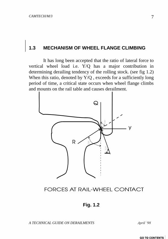
1.3 MECHANISM OF WHEEL FLANGE CLIMBING
It has long been accepted that the ratio of lateral force to
vertical wheel load i.e. Y/Q has a major contribution in
determining derailing tendency of the rolling stock. (see fig 1.2)
When this ratio, denoted by Y/Q , exceeds for a sufficiently long
period of time, a critical state occurs when wheel flange climbs
and mounts on the rail table and causes derailment.
Fig. 1.2
CAMTECH/M/3
A TECHNICAL GUIDE ON DERAILMENTS April ‘98
8
The simplest equation for the upper critical value of Y/Q
ratio to avoid flange mounting on rail derived by NADAL in
1908 (based on the simple analogy of a block sliding up an
inclined plane) is:
Y
Q
Tan
Tan
1
Where: = Coefficient of friction
= Flange angle
Y = Lateral flange force
Q = Wheel load
R = Normal reaction from rail
R = Frictional force acting upward
For safety against derailment, Y/Q should not exceed
1.4. This is considered the critical value. For Indian Railways,
this value has been further reduced and should lie between 0.8 &
1 for safe running.
For assessing the stability of a particular rolling stock, Y
and Q have to be measured at the rail-wheel contact. For laying
down a limiting value of Y/Q for safety, the right side
expression has to be evaluated. For this, we have to decide the
value to be taken for and . For large majority of wheels, =
680 (for new wheel profile). The value of depends on the
geometry of the surfaces in contact. On Indian Railways, the
value of in general is taken as 0.25. For = 680 and = 0.25,
the expression works out to approximately 1.4.1
1 Ministry of Railways, Government of India. Investigation of derailments.
(Pune: Indian Railway Institute of Civil Engineering,1995), p. 22.
CAMTECH/M/3
A TECHNICAL GUIDE ON DERAILMENTS April ‘98
9
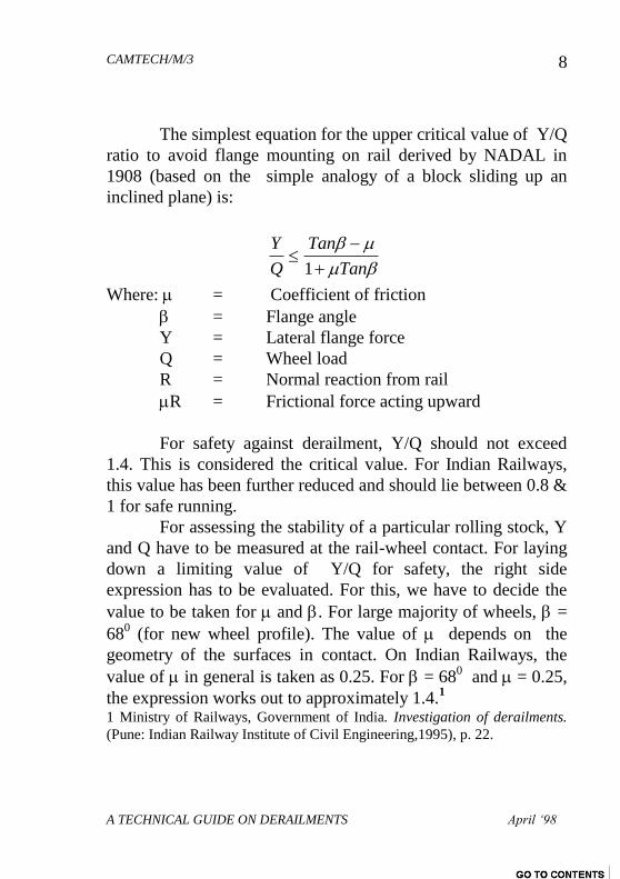
As already explained, there are two broad categories of
derailments: Sudden and Gradual. Nadal‟s formula deals only
with gradual derailment cases i.e. flange climbing. When the
ratio Y/Q reaches a critical value, it has to remain above such
value for certain minimum duration of time for flange to mount
on the rail and derail. A higher Y/Q ratio would be needed to
cause a derailment if the duration for which it acts is less. The
time frame followed all over the world is 5 milli-seconds as the
time duration which delineates the boundary between the two
categories of derailments. The final form of the criterion adopted
on Indian Railways is that derailment coefficient Y/Q should not
exceed 1.0. The said coefficient being measured over a duration
of 5 milli-seconds.
The various stages of wheel flange climbing on the rail
table during a gradual derailment are shown in the fig. 1.3.
Fig. 1.3 Stages of wheel Flange Climbing in a gradual derailment
CAMTECH/M/3
A TECHNICAL GUIDE ON DERAILMENTS April ‘98
10
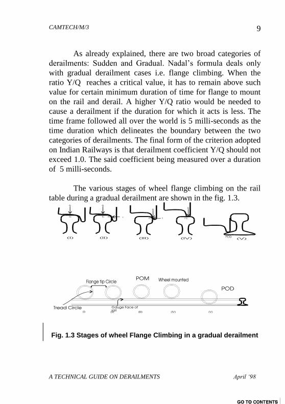
1.3.1 Angle Of Attack
Further attempts were made to refine NADAL‟S formula
given above. In further detailed studies, it was noticed that to
derail a wheel from the rail, another factor called “angle of
attack” plays a vital role. (See fig 1.4)
Fig. 1.4 Angle of Attack
The effect of angle of attack plays an important role in
derailment. The higher positive angle of attack increases
derailing tendency as the contact point of the flange with the rail
is then nearer the flange tip. This requires a lesser degree of
lateral force to cause flange mounting.
1.3.2 Angularity of Axle
Once the wheel lifts upto the end of straight portion of
flange, no additional force is required to further lift it i.e. the
rounded portion at the root of the flange does not prevent lifting.
The angularity of the axle (Fig. 1.5) shifts the point of contact
with flange down towards the root thus curtailing the amount of
lift required to derail the wheel.
CAMTECH/M/3
A TECHNICAL GUIDE ON DERAILMENTS April ‘98
11
.
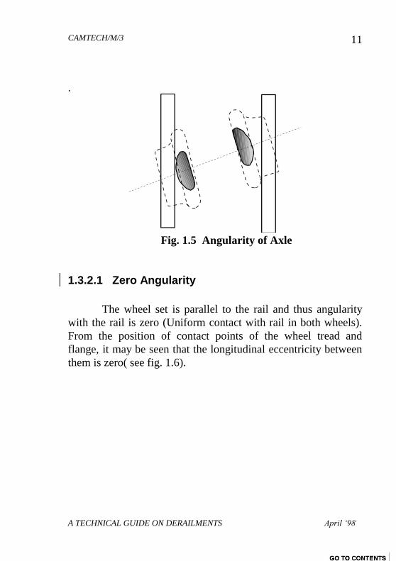
Fig. 1.5 Angularity of Axle
1.3.2.1 Zero Angularity
The wheel set is parallel to the rail and thus angularity
with the rail is zero (Uniform contact with rail in both wheels).
From the position of contact points of the wheel tread and
flange, it may be seen that the longitudinal eccentricity between
them is zero( see fig. 1.6).
CAMTECH/M/3
A TECHNICAL GUIDE ON DERAILMENTS April ‘98
12
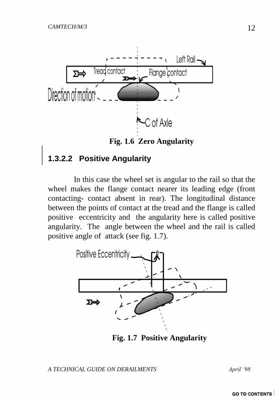
Fig. 1.6 Zero Angularity
1.3.2.2 Positive Angularity
In this case the wheel set is angular to the rail so that the
wheel makes the flange contact nearer its leading edge (front
contacting- contact absent in rear). The longitudinal distance
between the points of contact at the tread and the flange is called
positive eccentricity and the angularity here is called positive
angularity. The angle between the wheel and the rail is called
positive angle of attack (see fig. 1.7).
Fig. 1.7 Positive Angularity
CAMTECH/M/3
A TECHNICAL GUIDE ON DERAILMENTS April ‘98
13
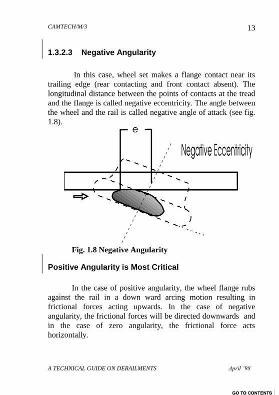
1.3.2.3 Negative Angularity
In this case, wheel set makes a flange contact near its
trailing edge (rear contacting and front contact absent). The
longitudinal distance between the points of contacts at the tread
and the flange is called negative eccentricity. The angle between
the wheel and the rail is called negative angle of attack (see fig.
1.8).
Fig. 1.8 Negative Angularity
Positive Angularity is Most Critical
In the case of positive angularity, the wheel flange rubs
against the rail in a down ward arcing motion resulting in
frictional forces acting upwards. In the case of negative
angularity, the frictional forces will be directed downwards and
in the case of zero angularity, the frictional force acts
horizontally.
CAMTECH/M/3
A TECHNICAL GUIDE ON DERAILMENTS April ‘98
14
Positive angularity is most critical of the above three
conditions. The derailment proneness is highest when the wheel
makes flange contact with the positive angle of attack. On
straight track, this configuration occurs only during certain
period of the oscillating motion of the wheel set. But on curves,
it occurs more or less throughout the period of curve negotiation.
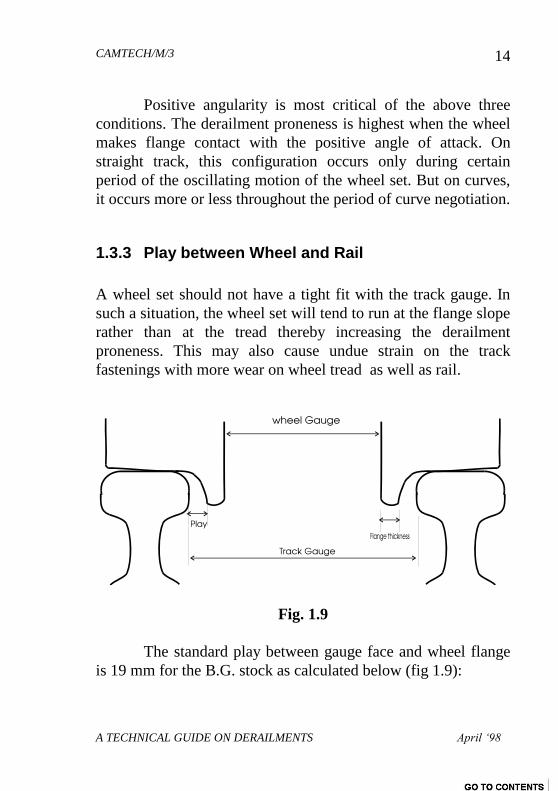
1.3.3 Play between Wheel and Rail
A wheel set should not have a tight fit with the track gauge. In
such a situation, the wheel set will tend to run at the flange slope
rather than at the tread thereby increasing the derailment
proneness. This may also cause undue strain on the track
fastenings with more wear on wheel tread as well as rail.
Fig. 1.9
The standard play between gauge face and wheel flange
is 19 mm for the B.G. stock as calculated below (fig 1.9):
CAMTECH/M/3
A TECHNICAL GUIDE ON DERAILMENTS April ‘98
15
= Gauge - (Wheel gauge + Two * Flange thickness)
= 1676 - (1600 + (2*28.5)
= 19 mm
Besides the above play, certain lateral and longitudinal
play is also provided on the vehicle to avoid undue straining of
vehicle components. These are :
play between Axle guard and Axle box
play between Brass and Journal collar etc.
Due to the above play and clearances, wheel set is able to
become angular to rails on run and thus it rarely runs parallel to
the rail but moves with varying angularity.
1.4 WHEEL OFF-LOADING
Whenever derailment takes place due to mounting of
flange on the rail, the flange first comes in contact with the
gauge face of the rail. As a result, a certain lateral force is
exerted on the track.. Another factor that comes into play is the
off-loading of wheel. The derailment of a wheel occurs when the
flange force exerted on the rail exceeds a critical value in
relation to the instantaneous wheel load. Most of the derailments
take place due to gradual off-loading and climbing of the wheel
flange on the rail table. It is evidenced in such cases that the
wheel travelled on the rail table for quite a few feet before
finally falling
CAMTECH/M/3
A TECHNICAL GUIDE ON DERAILMENTS April ‘98
16
outside the rail. But when the wheel off-loading is considerable,
the wheel may simply jump over the rail and derails leaving no
marks of mounting on the rail table.
In the case of flange climbing derailments, rolling stock
properties which reduce the wheel load or increase the flange
forces momentarily or permanently play an important role.
These may be expressed as static or dynamic properties and arise
from design characteristics of rolling stock and field conditions
during run.
The major cause of wheel unloading is the vehicle‟s
dynamic response to the vertical irregularities in the track. This
wheel unloading effect is perhaps the most important factor in
the majority of “Flange Climbing" derailments occurring at
normal speeds.
Reduction of vertical wheel load can also arise due to
uneven loading. The uneven loading can occur due to lack of
supervision during loading. This can also take place later due to
an evenly distributed load getting shifted in transit. In either
case, one side or one corner of the vehicle experiences a
permanent and significant loss of loading.
For various reasons, the wheel set travels along the track
executing a variety of oscillations. Lateral and vertical
oscillations force the wheel set to make flange contact with the
rail which results in development of lateral flange forces. The
excessive lateral flange forces are found to be another main
cause of derailment in large number of cases.
CAMTECH/M/3
A TECHNICAL GUIDE ON DERAILMENTS April ‘98
17
1.5 VEHICLE OSCILLATIONS DUE TO RAIL-
WHEEL INTERACTION
For any wheel to mount and derail, the flange tip must
get lifted to the top surface of the rail and then get displaced
laterally to drop on the other side. The factors contributing
towards oscillations and resulting in off-loading and lifting of
an individual wheel under running conditions are:
1.5.1 Unequal spring characteristics
1.5.2 Vertical irregularities of track
1.5.3 Uneven loading of wagon
1.5.4 Axle Load Variations during run
1.5.5 Dynamic Aspects
1.5.1 Unequal Spring Characteristics
The most important variation in the characteristics of
spring that contributes to asymmetrical distribution of weight is
free camber. The variation amongst the springs in the free
camber, especially those which are located at corners diagonally
opposite to each other, produce unequal load distribution on the
axles. The springs in service also loose some amount of free
camber with passage of time. As long as the difference in
camber at diagonally opposite springs is within reasonable
limits, there is little uneven distribution of load.
The shifting of spring buckles in relation to the spring
does not result in any significant uneven distribution of load
unless the free action of the spring is restricted. The cracks on
spring plates reduce the load bearing capacity of the spring but
CAMTECH/M/3
A TECHNICAL GUIDE ON DERAILMENTS April ‘98
18
this does not necessarily result in a derailment. But if the
complete spring collapses, there is a serious danger of
derailment.
1.5.2 Vertical Irregularities in Track
The variations in cross levels affect the distribution of
load on the axles. For details about the measurement of cross
levels, please refer to “ Track Defects”.
1.5.3 Uneven Loading
A vehicle is considered to be unevenly loaded when the
centre of gravity of the load is not in the same vertical axis as
that of centre of the vehicle.
1.5.4 Axle Load Variations during run
The distribution of the lateral forces between wheels
depends on the local contact conditions between the wheel and
the rail. If gradient is falling, the vehicle leans forward. Due to
cant, the vehicle also leans towards the inner rail. These
differences from the normal condition produce small increase in
the load on the wheels situated towards the inner rail. The
corresponding reduction on load takes place on wheels located
towards the outer rail side. Under these conditions, derailment
can occur due to lightly loaded rail which is generally the outer
rail on curves.
CAMTECH/M/3
A TECHNICAL GUIDE ON DERAILMENTS April ‘98
19
Thus even at very low speeds, serious adverse conditions
may occur due to combination of any or all of the following
factors:
Reduction in vertical wheel load due to cant.
Reduction in vertical wheel load due to a twisted vehicle.
Reduction in vertical wheel load due to an out of plane
track.
Lateral forces generated due to curve and other
oscillations.
Potentially high angle of attack presented to the leading
wheel in a sharp curve by the out side rail .
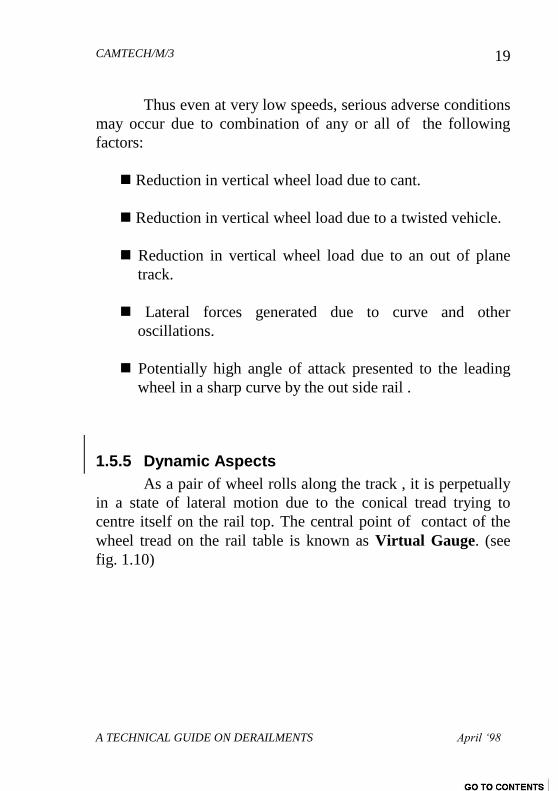
1.5.5 Dynamic Aspects
As a pair of wheel rolls along the track , it is perpetually
in a state of lateral motion due to the conical tread trying to
centre itself on the rail top. The central point of contact of the
wheel tread on the rail table is known as Virtual Gauge. (see
fig. 1.10)
CAMTECH/M/3
A TECHNICAL GUIDE ON DERAILMENTS April ‘98
20
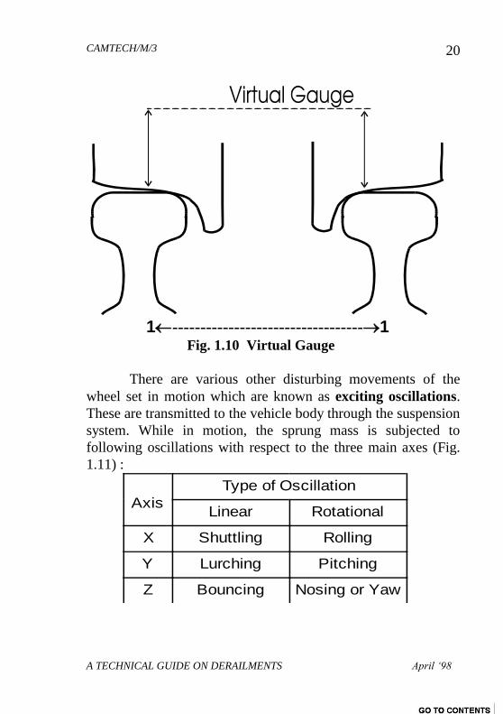
1----------------------------------1
Fig. 1.10 Virtual Gauge
There are various other disturbing movements of the
wheel set in motion which are known as exciting oscillations.
These are transmitted to the vehicle body through the suspension
system. While in motion, the sprung mass is subjected to
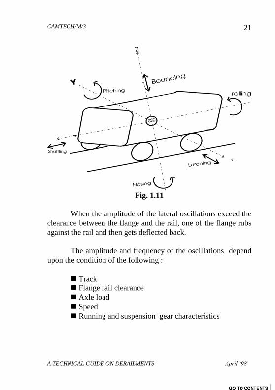
following oscillations with respect to the three main axes (Fig.
1.11) :
Axis
Type of Oscillation
Linear Rotational
X Shuttling Rolling
Y Lurching Pitching
Z Bouncing Nosing or Yaw
CAMTECH/M/3
A TECHNICAL GUIDE ON DERAILMENTS April ‘98
21
Fig. 1.11
When the amplitude of the lateral oscillations exceed the
clearance between the flange and the rail, one of the flange rubs
against the rail and then gets deflected back.
The amplitude and frequency of the oscillations depend
upon the condition of the following :
Track
Flange rail clearance
Axle load
Speed
Running and suspension gear characteristics
CAMTECH/M/3
A TECHNICAL GUIDE ON DERAILMENTS April ‘98
22
The lateral lurching and nosing oscillations give rise to
flange forces. The angularity of nosing also depends upon the
wheel base in relation to the track gauge. The shorter the wheel
base, the greater is the angularity.
1.6 LATERAL STABILITY OF TRACK
The following are the track parameters which determine
the extent of parasitic motion induced in the vehicle at a given
speed:
1. Alignment of the rail
2. Unevenness of the rails
3. Gauge
4. Cross level
5. Twist
6. Packing underneath the sleepers
7. Rail sleeper fastenings
8. Efficiency of drainage
9. Formation
10. Condition of ballast
11. Radius of curve
12. Transition length of the curve
13. Super elevation provided
14. Cant & Cant deficiency
15. Versine variation
16. Gap at rail joints
Out of the above, item no. 6 to 10 directly affect the
lateral stability of track. If the total effect of the above factors
develops lateral flange forces to such an extent that it overcomes
CAMTECH/M/3
A TECHNICAL GUIDE ON DERAILMENTS April ‘98
23
the lateral stability of track, it leads to spreading of gauge and
derailment of rolling stock.
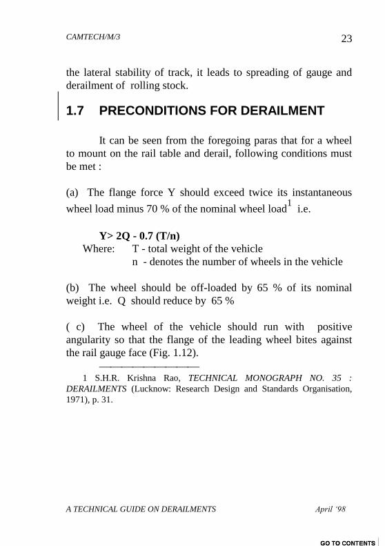
1.7 PRECONDITIONS FOR DERAILMENT
It can be seen from the foregoing paras that for a wheel
to mount on the rail table and derail, following conditions must
be met :
(a) The flange force Y should exceed twice its instantaneous
wheel load minus 70 % of the nominal wheel load1 i.e.
Y> 2Q - 0.7 (T/n)
Where: T - total weight of the vehicle
n - denotes the number of wheels in the vehicle
(b) The wheel should be off-loaded by 65 % of its nominal
weight i.e. Q should reduce by 65 %
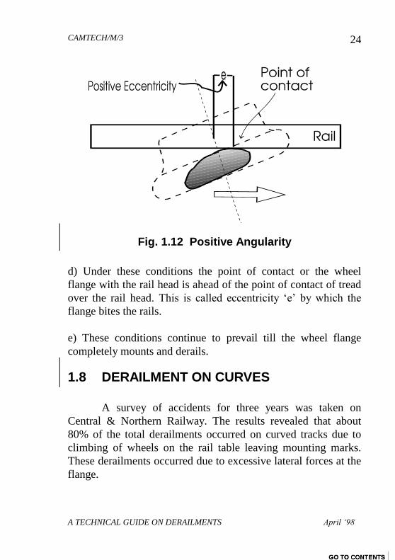
( c) The wheel of the vehicle should run with positive
angularity so that the flange of the leading wheel bites against
the rail gauge face (Fig. 1.12).
1 S.H.R. Krishna Rao, TECHNICAL MONOGRAPH NO. 35 :
DERAILMENTS (Lucknow: Research Design and Standards Organisation,
1971), p. 31.
CAMTECH/M/3
A TECHNICAL GUIDE ON DERAILMENTS April ‘98
24
Fig. 1.12 Positive Angularity
d) Under these conditions the point of contact or the wheel
flange with the rail head is ahead of the point of contact of tread
over the rail head. This is called eccentricity „e‟ by which the
flange bites the rails.
e) These conditions continue to prevail till the wheel flange
completely mounts and derails.
1.8 DERAILMENT ON CURVES
A survey of accidents for three years was taken on
Central & Northern Railway. The results revealed that about
80% of the total derailments occurred on curved tracks due to
climbing of wheels on the rail table leaving mounting marks.
These derailments occurred due to excessive lateral forces at the
flange.
CAMTECH/M/3
A TECHNICAL GUIDE ON DERAILMENTS April ‘98
25
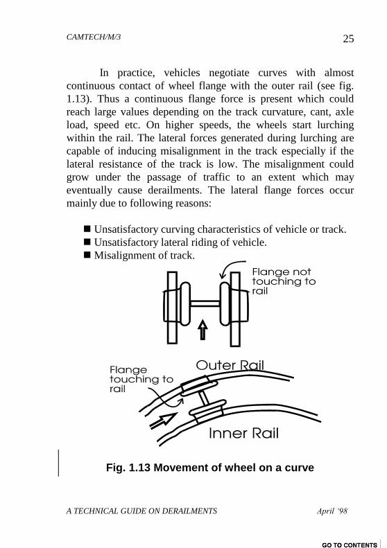
In practice, vehicles negotiate curves with almost
continuous contact of wheel flange with the outer rail (see fig.
1.13). Thus a continuous flange force is present which could
reach large values depending on the track curvature, cant, axle
load, speed etc. On higher speeds, the wheels start lurching
within the rail. The lateral forces generated during lurching are
capable of inducing misalignment in the track especially if the
lateral resistance of the track is low. The misalignment could
grow under the passage of traffic to an extent which may
eventually cause derailments. The lateral flange forces occur
mainly due to following reasons:
Unsatisfactory curving characteristics of vehicle or track.
Unsatisfactory lateral riding of vehicle.
Misalignment of track.
Fig. 1.13 Movement of wheel on a curve
CAMTECH/M/3
A TECHNICAL GUIDE ON DERAILMENTS April ‘98
26
On negotiating a curve with significant positive angle of
attack at the leading outer wheel, the derailment coefficient Y/Q
may reach its limiting value. If cant is given in excess then even
greater positive angle of attack will develop at the leading outer
wheel which will further increase the chances of derailment.
CAMTECH/M/3
A TECHNICAL GUIDE ON DERAILMENTS April ‘98
27
CHAPTER 2
SITE INVESTIGATION
Unless reasons for derailment are obvious from the
initial inspection at site, comprehensive investigation in a logical
sequence is needed to ascertain the actual cause of derailment.
The site investigation is primarily concerned with identification
of evidence and related data before restoring the track and
vehicles. The main purposes are to :
1. Locate the initial point of derailment
2. To identify the first derailed vehicle and wheel
3. To obtain sufficient evidence to determine the course of
events up to the time derailed train came to a halt and
4. To explain why the vehicle derailed initially at that
particular point on the track.
The site investigation should be carried out in the
following sequence :
1. First considerations
2. Site sketch
3. Flange marks
4. Operational Defects/Failures
5. Track survey and examination
6. Vehicle examination
CAMTECH/M/3
A TECHNICAL GUIDE ON DERAILMENTS April ‘98
28
2.1 FIRST CONSIDERATIONS
The sequence of events to be recorded i.e. how
derailment occurred prima facie, from the beginning to the time
the train came to a halt. The position of vehicles after derailment
must be recorded. The wheel marks at the initial point of
derailment are to be examined in order to establish the category
of derailment i.e. sudden or gradual.
It is important for the investigators to make rapid
observations and record the position of vehicles. It is also
important that such a survey must be completed before the
restoration work commences on the track especially in the rear
of point of derailment.
2.2 SITE SKETCH
A sketch of the whole site showing the position of
derailed vehicles relative to both rails as well as other evidences
if any together with the track damages must be prepared. If this
is not done, serious difficulties will be encountered later when
this evidence is required for correlating the events relating to
vehicle and track interaction.
2.3 FLANGE MARKS ON THE RAIL
The most important thing in investigating the
derailments is to locate and examine the wheel mounting marks
or the marks at the initial point of derailment in order to
determine whether the derailment was sudden or gradual.
CAMTECH/M/3
A TECHNICAL GUIDE ON DERAILMENTS April ‘98
29
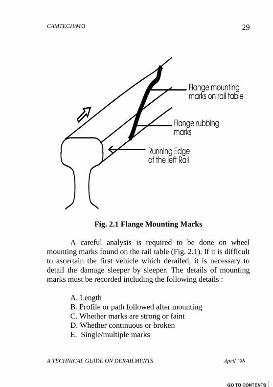
Fig. 2.1 Flange Mounting Marks
A careful analysis is required to be done on wheel
mounting marks found on the rail table (Fig. 2.1). If it is difficult
to ascertain the first vehicle which derailed, it is necessary to
detail the damage sleeper by sleeper. The details of mounting
marks must be recorded including the following details :
A. Length
B. Profile or path followed after mounting
C. Whether marks are strong or faint
D. Whether continuous or broken
E. Single/multiple marks
CAMTECH/M/3
A TECHNICAL GUIDE ON DERAILMENTS April ‘98
30
Preferably, photographs should be taken not only of
mounting marks found on the rail but also those found on the
sleeper fastenings and ballast. These marks must be carefully
noted and measured.
Often many vehicles derail before the train comes to halt.
This creates multiplicity of wheel mounting marks. Thus it
becomes necessary to identify the particular wheel set which
derailed first. This can only be achieved by matching the length
and nature of various trail marks left by wheels against the
position and orientation of derailed vehicles, analysis of marks
on the wheel tread and flanges, damage to vehicles and wheel
sets etc.
2.4 OPERATIONAL DEFECTS/FAILURES
The following are the major operational features which
are significant in a derailment:
2.4.1 Speed
The speed of train plays a vital role in derailments. If
speed is in excess of permissible speed, lateral forces on the
flange increase and the formation may not be able to resist this
increased force thereby resulting in either flange mounting or
jumping off from the rail table.
Under dynamic conditions, the speed of train plays a
vital part in derailment of a vehicle. Higher the speed, smaller
will be the range of permissible imperfections on the track and
CAMTECH/M/3
A TECHNICAL GUIDE ON DERAILMENTS April ‘98
31
rolling stock. The rolling stock by virtue of its spring and
suspension system responds to the disturbances and is free to
perform inherent oscillations. As the rolling stock moves over
the track, exciting oscillations are produced and the exciting
frequency directly depends upon the speed. Conditions of -
resonance may occur if the exciting frequency approaches the
natural frequency. The oscillations become more pronounced
while the train is coasting i.e. when the drawbar pull is absent.
The amplitude of these oscillations increase with increase in
speed especially if the causative factors amplifying the
oscillations are present.
It will therefore be seen that the wheel load changes due
to oscillations on run. The degree of track imperfections, state of
maintenance on rolling stock, its suspension characteristics,
disposition of load on wheels and speed are the main items of
attention in the investigation of a derailment.
2.4.2 Loading
Irregular or excess loading may lead to derailment of a
vehicle as the wheel may float due to off-loading..
2.4.3 Wrong Marshalling
Empty stock marshalled in between two loaded wagons
forces the empty stock, specially the four wheeler units, to jump
off under the impact of draw bar forces and derail.
CAMTECH/M/3
A TECHNICAL GUIDE ON DERAILMENTS April ‘98
32
2.4.4 Mismanipulation of Point
Due to mismanipulation of a point under movement,
derailment occurs. In such cases the leading wheel or trolley will
travel on one side of the track and the trailing trolley will travel
on the other track. This happens on points in facing direction
only. In such cases, the important points to be checked are :
A. Length of tongue rail
B. Rigid wheel base of the stock
C. Gap between toe of switch and stock rail
By examination of the above factors, one can ascertain
whether the point was operated under movement. Another aspect
which is not pertaining to operational failures but must be
checked is whether the point was working freely and correctly.
2.4.5 Operating Staff Failure
Following problems may also result in a derailment :
Points not being properly set and locked during
shunting operation at the station.
Operation of point under wheel movement.
Undetected obstruction between toe of switch and
stock rail
Loose couplings
CAMTECH/M/3
A TECHNICAL GUIDE ON DERAILMENTS April ‘98
33
2.4.6 Improper Train Operation by the Driver
Sudden application of brakes cause bunching and off
loading of light loaded wheels. This may also result in
derailments.
2.5 ROLLING STOCK EXAMINATION
The details are given in Chapter 3.
2.6 TRACK SURVEY AND EXAMINATION
The details are given in Chapter 4 and 5.
CAMTECH/M/3
A TECHNICAL GUIDE ON DERAILMENTS April ‘98
34
CHAPTER 3
INSPECTION OF ROLLING STOCK
The rolling stock involved in accident must be inspected
in the presence of nominated team of supervisors and results
should be recorded in the prescribed format (Appendix ‘A’).
The main items of inspection are as under :
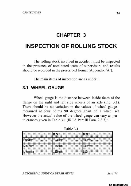
3.1 WHEEL GAUGE
Wheel gauge is the distance between inside faces of the
flange on the right and left side wheels of an axle (Fig. 3.1).
There should be no variation in the values of wheel gauge -
measured at four points 90 degrees apart on a wheel set.
However the actual value of the wheel gauge can vary as per -
tolerances given in Table 3.1 (IRCA Part III Para. 2.8.7) :
Table 3.1
B.G. M.G.
Standard 1600 mm 930mm
Maximum 1602mm 932mm
Minimum 1599mm 929mm
CAMTECH/M/3
A TECHNICAL GUIDE ON DERAILMENTS April ‘98
35
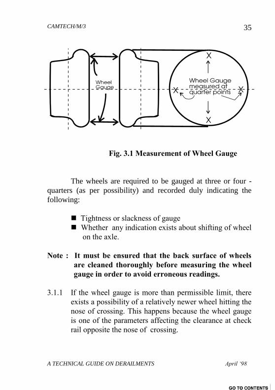
Fig. 3.1 Measurement of Wheel Gauge
The wheels are required to be gauged at three or four -
quarters (as per possibility) and recorded duly indicating the
following:
Tightness or slackness of gauge
Whether any indication exists about shifting of wheel
on the axle.
Note : It must be ensured that the back surface of wheels
are cleaned thoroughly before measuring the wheel
gauge in order to avoid erroneous readings.
3.1.1 If the wheel gauge is more than permissible limit, there
exists a possibility of a relatively newer wheel hitting the
nose of crossing. This happens because the wheel gauge
is one of the parameters affecting the clearance at check
rail opposite the nose of crossing.
CAMTECH/M/3
A TECHNICAL GUIDE ON DERAILMENTS April ‘98
36
3.1.2 If the wheel gauge is less than minimum value, there is a
possibility of wheel hitting at the back of a tongue rail
while passing through the switch and thus damaging the
tongue rail.
3.1.3 The variation in wheel gauge after lowering the coach
body on wheels was examined by RDSO Lucknow and
circulated to all Railways vide their letter no.
MC/WA/GENL Dated 27.6.88 as follows :
“ The question of variation in the
wheel gauge under no-load and loaded
condition has been examined by RDSO. The
calculations for the 15 ton BG axle under tare
load condition indicates that a variation of
about 3 mm in the wheel gauge when
measured at the top and bottom locations in
the vertical plane is likely to take place due to
bending of axle under coach load
This variation in wheel gauge under
loaded condition, however, has no bearing on
the safety of coach operation. However, if the
measurements for wheel gauge are done in
horizontal plane passing through the axle then
the effect of bending of the axle will not be
there.
It is therefore clarified that the wheel gauge
tolerances of 1600 2 mm as laid down in IRCA rule book
CAMTECH/M/3
A TECHNICAL GUIDE ON DERAILMENTS April ‘98
37
is required to be checked under "No-load" conditions.
3.2 BENT AXLE
A bent axle starts wobbling during motion causing
severe vibrations. In order to confirm whether an axle is bent or
not, it must be checked carefully on a sensitive machine or
measuring table.
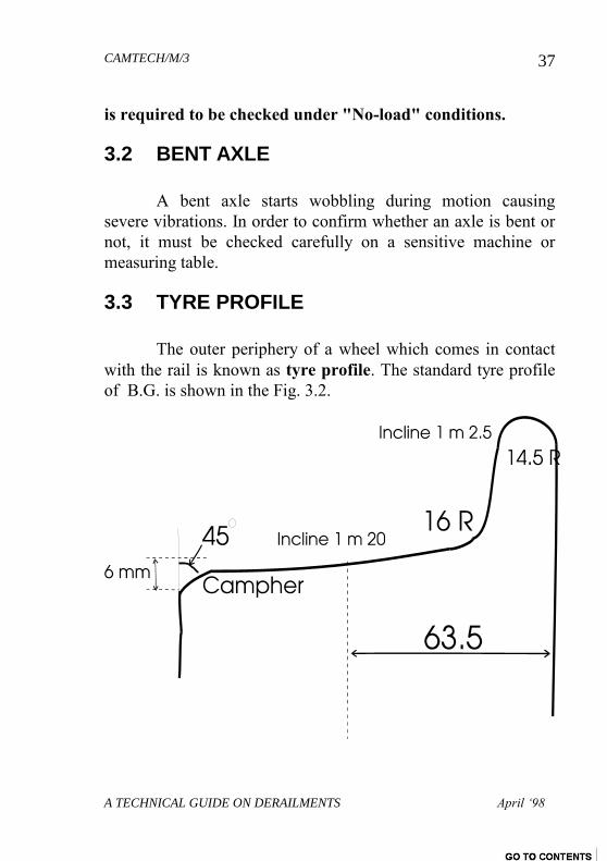
3.3 TYRE PROFILE
The outer periphery of a wheel which comes in contact
with the rail is known as tyre profile. The standard tyre profile
of B.G. is shown in the Fig. 3.2.
CAMTECH/M/3
A TECHNICAL GUIDE ON DERAILMENTS April ‘98
38
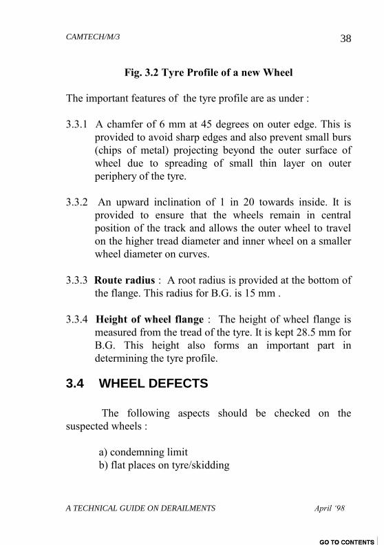
Fig. 3.2 Tyre Profile of a new Wheel
The important features of the tyre profile are as under :
3.3.1 A chamfer of 6 mm at 45 degrees on outer edge. This is
provided to avoid sharp edges and also prevent small burs
(chips of metal) projecting beyond the outer surface of
wheel due to spreading of small thin layer on outer
periphery of the tyre.
3.3.2 An upward inclination of 1 in 20 towards inside. It is
provided to ensure that the wheels remain in central
position of the track and allows the outer wheel to travel
on the higher tread diameter and inner wheel on a smaller
wheel diameter on curves.
3.3.3 Route radius : A root radius is provided at the bottom of
the flange. This radius for B.G. is 15 mm .
3.3.4 Height of wheel flange : The height of wheel flange is
measured from the tread of the tyre. It is kept 28.5 mm for
B.G. This height also forms an important part in
determining the tyre profile.
3.4 WHEEL DEFECTS
The following aspects should be checked on the
suspected wheels :
a) condemning limit
b) flat places on tyre/skidding
CAMTECH/M/3
A TECHNICAL GUIDE ON DERAILMENTS April ‘98
39
c) flanges - sharp/deep/thin
d) radius too small at the root of the flange
e) gauge slack/tight.
f) cracks
The above mentioned defects can be detected with the
help of Tyre defect gauge and Wheel gauge meant for this
purpose.
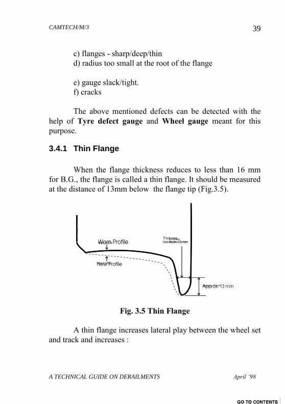
3.4.1 Thin Flange
When the flange thickness reduces to less than 16 mm
for B.G., the flange is called a thin flange. It should be measured
at the distance of 13mm below the flange tip (Fig.3.5).
Fig. 3.5 Thin Flange
A thin flange increases lateral play between the wheel set
and track and increases :
CAMTECH/M/3
A TECHNICAL GUIDE ON DERAILMENTS April ‘98
40
Lateral oscillations adversely affecting Y/Q and
Angularity of wheel set on run
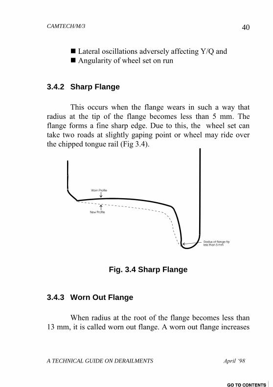
3.4.2 Sharp Flange
This occurs when the flange wears in such a way that
radius at the tip of the flange becomes less than 5 mm. The
flange forms a fine sharp edge. Due to this, the wheel set can
take two roads at slightly gaping point or wheel may ride over
the chipped tongue rail (Fig 3.4).
Fig. 3.4 Sharp Flange
3.4.3 Worn Out Flange
When radius at the root of the flange becomes less than
13 mm, it is called worn out flange. A worn out flange increases
CAMTECH/M/3
A TECHNICAL GUIDE ON DERAILMENTS April ‘98
41
the value of (Fig.
Fig. 3.5 Worn out Flange
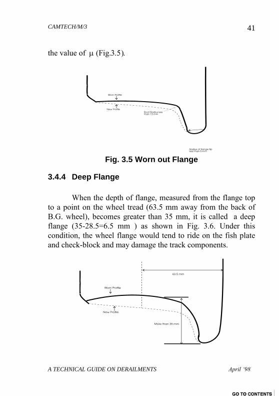
3.4.4 Deep Flange
When the depth of flange, measured from the flange top
to a point on the wheel tread (63.5 mm away from the back of
B.G. wheel), becomes greater than 35 mm, it is called a deep
flange (35-28.5=6.5 mm ) as shown in Fig. 3.6. Under this
condition, the wheel flange would tend to ride on the fish plate
and check-block and may damage the track components.
CAMTECH/M/3
A TECHNICAL GUIDE ON DERAILMENTS April ‘98
42
Fig. 3.6 Deep Flange
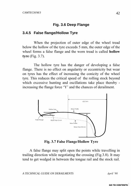
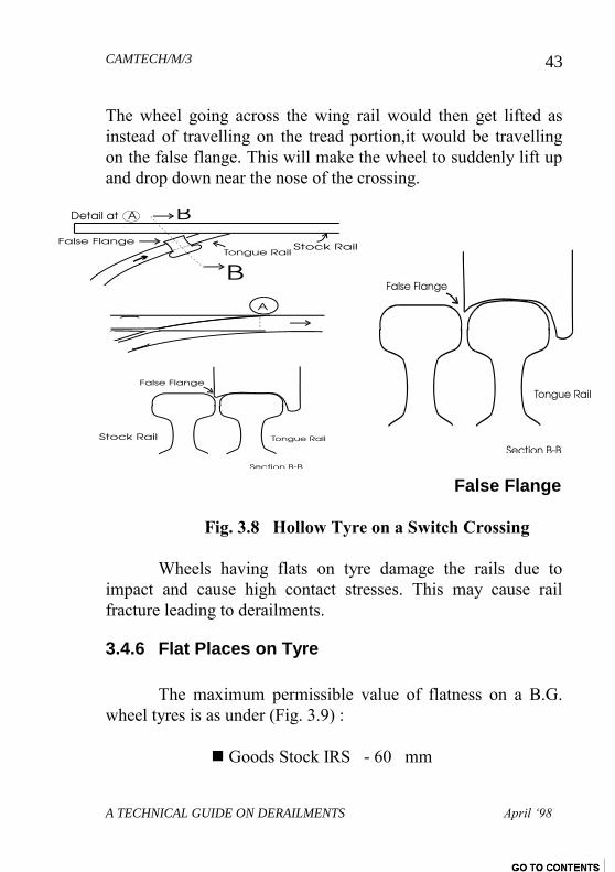
3.4.5 False flange/Hollow Tyre
When the projection of outer edge of the wheel tread
below the hollow of the tyre exceeds 5 mm, the outer edge of the
wheel forms a false flange and the worn tread is called hollow
tyre (Fig. 3.7).
The hollow tyre has the danger of developing a false
flange. There is no effect on angularity or eccentricity but wear
on tyres has the effect of increasing the conicity of the wheel
tyre. This reduces the critical speed of the rolling stock beyond
which excessive hunting and oscillations take place thereby -
increasing the flange force ‘Y’ and the chances of derailment.
Fig. 3.7 False Flange/Hollow Tyre
A false flange may split open the points while travelling in
trailing direction while negotiating the crossing (Fig.3.8). It may
tend to get wedged in between the tongue rail and the stock rail.
CAMTECH/M/3
A TECHNICAL GUIDE ON DERAILMENTS April ‘98
43
The wheel going across the wing rail would then get lifted as
instead of travelling on the tread portion,it would be travelling
on the false flange. This will make the wheel to suddenly lift up
and drop down near the nose of the crossing.
False Flange
Fig. 3.8 Hollow Tyre on a Switch Crossing
Wheels having flats on tyre damage the rails due to
impact and cause high contact stresses. This may cause rail
fracture leading to derailments.
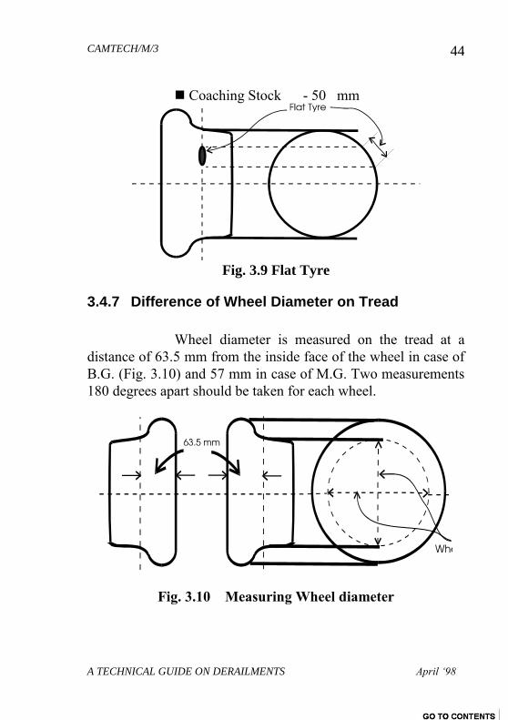
3.4.6 Flat Places on Tyre
The maximum permissible value of flatness on a B.G.
wheel tyres is as under (Fig. 3.9) :
Goods Stock IRS - 60 mm
CAMTECH/M/3
A TECHNICAL GUIDE ON DERAILMENTS April ‘98
44
Coaching Stock - 50 mm
Fig. 3.9 Flat Tyre
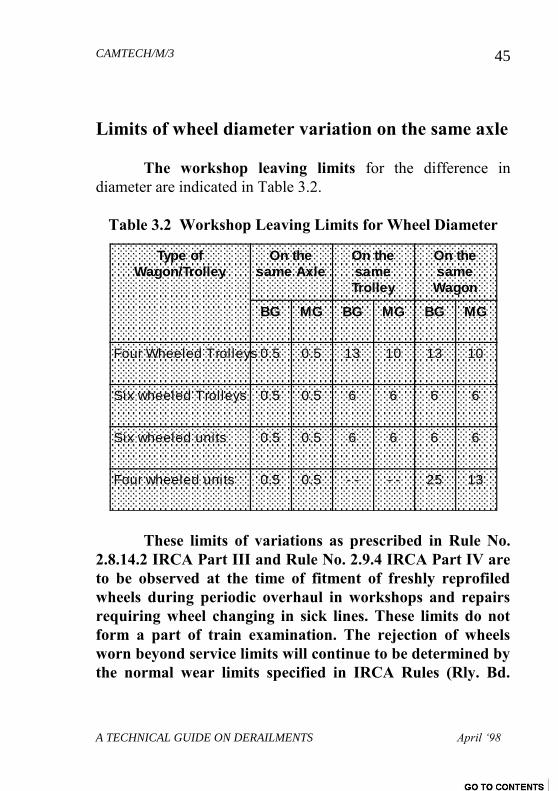
3.4.7 Difference of Wheel Diameter on Tread
Wheel diameter is measured on the tread at a
distance of 63.5 mm from the inside face of the wheel in case of
B.G. (Fig. 3.10) and 57 mm in case of M.G. Two measurements
180 degrees apart should be taken for each wheel.
Fig. 3.10 Measuring Wheel diameter
CAMTECH/M/3
A TECHNICAL GUIDE ON DERAILMENTS April ‘98
45
Limits of wheel diameter variation on the same axle
The workshop leaving limits for the difference in
diameter are indicated in Table 3.2.
Table 3.2 Workshop Leaving Limits for Wheel Diameter
Type of
Wagon/Trolley
On the
same Axle
On the
same
Trolley
On the
same
Wagon
BG MG BG MG BG MG
Four Wheeled Trolleys 0.5 0.5 13 10 13 10
Six wheeled Trolleys 0.5 0.5 6 6 6 6
Six wheeled units 0.5 0.5 6 6 6 6
Four wheeled units 0.5 0.5 - - - - 25 13
These limits of variations as prescribed in Rule No.
2.8.14.2 IRCA Part III and Rule No. 2.9.4 IRCA Part IV are
to be observed at the time of fitment of freshly reprofiled
wheels during periodic overhaul in workshops and repairs
requiring wheel changing in sick lines. These limits do not
form a part of train examination. The rejection of wheels
worn beyond service limits will continue to be determined by
the normal wear limits specified in IRCA Rules (Rly. Bd.
CAMTECH/M/3
A TECHNICAL GUIDE ON DERAILMENTS April ‘98
46
letter No. 86/M(N)960/8 DATED 22.8.86).
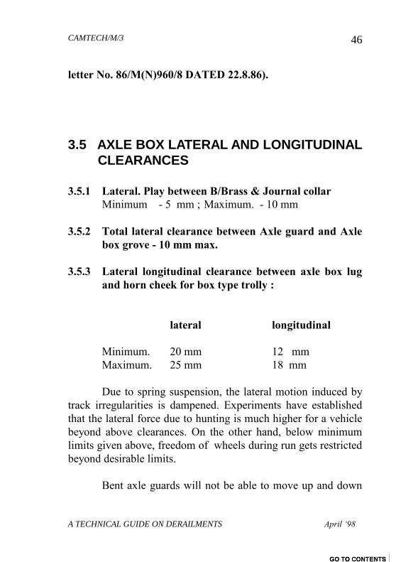
3.5 AXLE BOX LATERAL AND LONGITUDINAL
CLEARANCES
3.5.1 Lateral. Play between B/Brass & Journal collar
Minimum - 5 mm ; Maximum. - 10 mm
3.5.2 Total lateral clearance between Axle guard and Axle
box grove - 10 mm max.
3.5.3 Lateral longitudinal clearance between axle box lug
and horn cheek for box type trolly :
lateral longitudinal
Minimum. 20 mm 12 mm
Maximum. 25 mm 18 mm
Due to spring suspension, the lateral motion induced by
track irregularities is dampened. Experiments have established
that the lateral force due to hunting is much higher for a vehicle
beyond above clearances. On the other hand, below minimum
limits given above, freedom of wheels during run gets restricted
beyond desirable limits.
Bent axle guards will not be able to move up and down
CAMTECH/M/3
A TECHNICAL GUIDE ON DERAILMENTS April ‘98
47
freely and the axle box will get jammed making spring assembly
ineffective thus increasing proneness to derailment.
3.6 BUFFING GEAR
3.6.1 Buffer projection limits from head stock
For long case buffers For short case buffers
Max. 635 mm 456 mm
Min. 584 mm 406 mm
A. Buffer projection for POH stock should not be less
then 625 mm for long case and 445 mm for short
case buffers.
B. No dead buffers shall be permitted from the sick line.
The buffers shall be considered dead when the
projection is below the prescribed minimum Limits.
C. Buffer heights in BG Stock shall be within the limits
shown above and it should be measured on level
track.
Note: The measurement should be taken from the centre of
the buffer socket to the top of the rail head. The
buffer height should never be taken from the centre
of the buffer face because it will not give correct
value.
While recording buffer height, it should be ensured that
CAMTECH/M/3
A TECHNICAL GUIDE ON DERAILMENTS April ‘98
48
buffer bolts are in tight condition and buffer is not drooping. If it
is drooping, the amount of drooping should be measured and
recorded.
To make up buffer heights to maximum permissible limits, a
packing piece of required design and size may be inserted :
For Goods stock : between axle box crown & bearing
spring buckles.
For ICF coaching stock : between lower spring (Dash Pot
spring) & axle box wing.
3.6.2 Displaced Buffer
Buffer displaced 35 mm in any direction from its normal
position in case of goods stock and 38 mm for coaching stock
are called displaced buffers.
If buffers of adjacent stock are not in the same level due
to different conditions of loading or spring characteristics, the
buffer draw gear takes an inclined position. In case of sag on the
track or brake application on a down gradient, the buffers exert
compressive forces. It makes the lighter vehicle prone to
derailment due to lifting because of vertical component of the -
buffing force.
3.7 SPRING AND SPRING GEAR
In four wheeler stock, laminated springs are normally
used. However in coaches now, mostly coil springs are used.
CAMTECH/M/3
A TECHNICAL GUIDE ON DERAILMENTS April ‘98
49
The defects in these can be classified into three main categories :
3.7.1 Defects affecting the functioning of springs
If the defects are such that normal functioning gets
hampered, the load transmission system is adversely affected.
The particular wheel on which this spring bears can’t adjust
itself to any unevenness in the track and the wheel will become
prone to derailment due to lack of dampening force.
3.7.2 Variation in performance of different springs on
the same vehicle
The difference in working camber amongst the four
springs under load should not exceed 13 mm. The springs
having different cambers may cause derailment due to off-
loading effect.
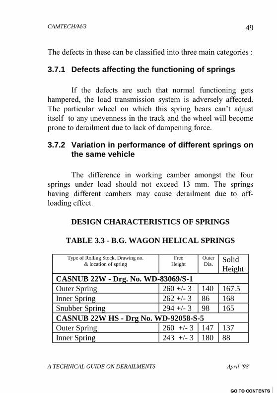
DESIGN CHARACTERISTICS OF SPRINGS
TABLE 3.3 - B.G. WAGON HELICAL SPRINGS
Type of Rolling Stock, Drawing no.
& location of spring
Free
Height
Outer
Dia. Solid
Height
CASNUB 22W - Drg. No. WD-83069/S-1
Outer Spring 260 +/- 3 140 167.5
Inner Spring 262 +/- 3 86 168
Snubber Spring 294 +/- 3 98 165
CASNUB 22W HS - Drg No. WD-92058-S-5
Outer Spring 260 +/- 3 147 137
Inner Spring 243 +/- 3 180 88
CAMTECH/M/3
A TECHNICAL GUIDE ON DERAILMENTS April ‘98
50
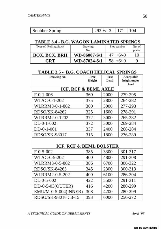
Snubber Spring 293 +/- 3 171 104
TABLE 3.4 - B.G. WAGON LAMINATED SPRINGS Type of Rolling Stock Drawing
No.
Free camber No. of
plates
BOX, BCX, BRH WD-86007-S/1 47 +6/-0 10
CRT WD-87024-S/1 58 +6/-0 9
TABLE 3.5 - B.G. COACH HELICAL SPRINGS Drawing No. Free
Height
Test
Load
Acceptable
height under
load
ICF, RCF & BEML AXLE
F-0-1-006 360 2000 279-295
WTAC-0-1-202 375 2800 264-282
WLRRM8-0-1-802 360 3000 277-293
RDSO/SK-84262 325 1600 278-291
WLRRM2-0-1202 372 3000 265-282
DL-0-1-002 372 3000 269-284
DD-0-1-001 337 2400 268-284
RDSO/SK-98017 315 1800 276-289
ICF, RCF & BEML BOLSTER
F-0-5-002 385 3300 301-317
WTAC-0-5-202 400 4800 291-308
WLRRM8-0-5-802 386 6700 306-322
RDSO/SK-84263 345 2300 300-313
WLRRM2-0-5-202 400 6100 286-304
DL-0-5-002 422 5500 291-311
DD-0-5-03(OUTER)
EMU/M-0-5-004(INNER)
416
308
4200
4200
280-299
280-299
RDSO/SK-98018 : B-15 393 6000 256-272
CAMTECH/M/3
A TECHNICAL GUIDE ON DERAILMENTS April ‘98
51
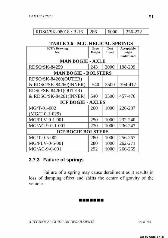
RDSO/SK-98018 : B-16 286 6000 256-272
TABLE 3.6 - M.G. HELICAL SPRINGS ICF’s Drawing
No.
Free
Height
Test
Load
Acceptable
height
under load
MAN BOGIE - AXLE
RDSO/SK-84259 243 2000 198-209
MAN BOGIE - BOLSTERS
RDSO/SK-84260(OUTER)
& RDSO/SK-84260(INNER)
540
3500
394-417
RDSO/SK-84261(OUTER)
& RDSO/SK-84261(INNER)
540
3500
457-476
ICF BOGIE - AXLES
MG/T-01-002
(MG/T-0-1-029)
260 1000 226-237
MG/PLV-0-1-001 250 1000 232-240
MG/AC-9-0-1-001 270 1000 236-247
ICF BOGIE BOLSTERS
MG/T-0-5-002
MG/PLV-0-5-001
MG/AC-9-0-001
280
280
292
1000
1000
1000
256-267
262-271
266-269
3.7.3 Failure of springs
Failure of a spring may cause derailment as it results in
loss of damping effect and shifts the centre of gravity of the
vehicle.
CAMTECH/M/3
A TECHNICAL GUIDE ON DERAILMENTS April ‘98
52
CHAPTER 4
PERMANENT WAY
The track structure consists of following four main
components :
1. Formation
2. Ballast
3. Sleepers and fastenings
4. Rails
These are required to be regularly and periodically
checked by Assistant Engineer (IRPWM para 107), PWI
(IRPWM para 123,124 & 139) as well as by P.Way Mistries,
Mates and Keymen (IRPWM Part ‘C’).
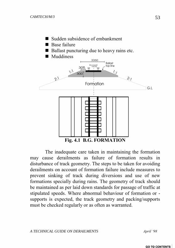
4.1 FORMATION
The railway track is laid over a formation prepared on
soil (Fig. 4.1). The strength of formation depends upon the type
of soil i.e. sandy, loam clay etc. and it serves the following
purposes:
distributes the weight of train, track and ballast over a
wide area of natural ground
facilitates good drainage and
provides a smooth and regular surface on which the
ballast and track can be laid
The formation is affected by following factors:
CAMTECH/M/3
A TECHNICAL GUIDE ON DERAILMENTS April ‘98
53
Sudden subsidence of embankment
Base failure
Ballast puncturing due to heavy rains etc.
Muddiness
Fig. 4.1 B.G. FORMATION
The inadequate care taken in maintaining the formation
may cause derailments as failure of formation results in
disturbance of track geometry. The steps to be taken for avoiding
derailments on account of formation failure include measures to
prevent sinking of track during diversions and use of new
formations specially during rains. The geometry of track should
be maintained as per laid down standards for passage of traffic at
stipulated speeds. Where abnormal behaviour of formation or -
supports is expected, the track geometry and packing/supports
must be checked regularly or as often as warranted.
CAMTECH/M/3
A TECHNICAL GUIDE ON DERAILMENTS April ‘98
54
4.2 BALLAST
In the track geometry, ballast plays an important role. It
absorbs noise, shocks, vibrations and distributes the load
transmitted by the wheels over the formation. The ballast
provides a flexible base to the track and controls the lateral and
longitudinal movement of track. It keeps the track in position
and at required level. If sufficient quantity of ballast is not
available, track may get distorted andor buckled. The
recommended ballast size is 50 mm. The profiles and minimum
depths should be as given in Para. 263 of IRPWM.
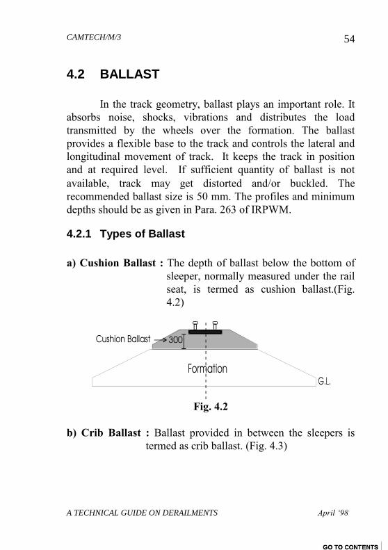
4.2.1 Types of Ballast
a) Cushion Ballast : The depth of ballast below the bottom of
sleeper, normally measured under the rail
seat, is termed as cushion ballast.(Fig.
4.2)
Fig. 4.2
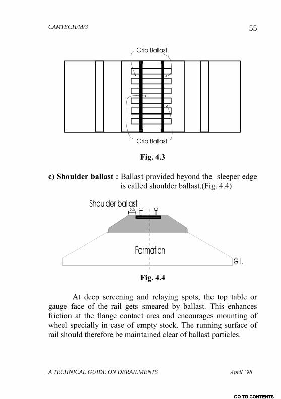
b) Crib Ballast : Ballast provided in between the sleepers is
termed as crib ballast. (Fig. 4.3)
CAMTECH/M/3
A TECHNICAL GUIDE ON DERAILMENTS April ‘98
55
Fig. 4.3
c) Shoulder ballast : Ballast provided beyond the sleeper edge
is called shoulder ballast.(Fig. 4.4)
Fig. 4.4
At deep screening and relaying spots, the top table or
gauge face of the rail gets smeared by ballast. This enhances
friction at the flange contact area and encourages mounting of
wheel specially in case of empty stock. The running surface of
rail should therefore be maintained clear of ballast particles.
CAMTECH/M/3
A TECHNICAL GUIDE ON DERAILMENTS April ‘98
56
4.2.2 Ballast Resistance
The ballast plays an important role in absorbing shocks.
The factors affecting the ballast resistance are :
Ballast material
Size
Shape of ballast particle
Ballast profile
State of consolidation
Type of sleeper
4.3 SLEEPERS AND FASTENINGS
The sleepers and fastenings hold the rails within desired
gauge parameters. If sleepers and fastenings fail, entire geometry
of the track gets disturbed and the rails may shift from their due
position. The loosening or failure of fastenings also indicate
lateral distortion of rails under load. Thus they perform the
following functions :
To hold the rails as per desired gauge limits
To transmit the load from rail to a wider area over the
ballast.
To provide resilient support with ability to absorb high
frequency vibrations
To provide lateral and longitudinal strength to the track
To permit rectification of track geometry
Be amenable to packing and retain it
To resist longitudinal creep of rail
CAMTECH/M/3
A TECHNICAL GUIDE ON DERAILMENTS April ‘98
57
To resist overturning of rail
Types of Sleepers are :
1. Wooden
2. CST 9 Cast Iron
3. Steel trough
4. Concrete
The various fastenings used are bearing plates, fish
plates, Screws, Spikes, Steel keys, cotters, Pandrol clips etc.
The density and condition of sleepers should be maintained as
prescribed in IRPWM. If ‘M’ is the Standard Single rail
length in meters, the minimum sleeper densities as per
IRPWM Para. 244 (4) are as follows :
B.G. a) Traffic density more than 10 G.M.T.
M+7 for Group A,B,C & D Routes
M+4 for Group E Routes
b) Traffic density less than 10 G.M.T.
M+7 for Group A,B & C Routes
M+4 for Group D & E Routes
M.G. M+7 for Q,R1 & R2 Groups; M+4 for R3;
and M+3 for S Group of Routes.
For prescribed sleeper spacing on various type of
tracks, refer to IRPWM para. 244 (2) .
The orientation of sleepers to be checked by means of the gauge
meant for this purpose. (All sleepers must be laid at right
angles to the rail.)
CAMTECH/M/3
A TECHNICAL GUIDE ON DERAILMENTS April ‘98
58
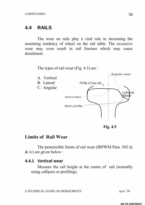
4.4 RAILS
The wear on rails play a vital role in increasing the
mounting tendency of wheel on the rail table. The excessive
wear may even result in rail fracture which may cause
derailment.
The types of rail wear (Fig. 4.5) are :
A. Vertical
B. Lateral
C. Angular
Fig. 4.5
Limits of Rail Wear
The permissible limits of rail wear (IRPWM Para. 302 iii
& iv) are given below :
4.4.1 Vertical wear
Measure the rail height at the centre of rail (normally
using callipers or profiling).
CAMTECH/M/3
A TECHNICAL GUIDE ON DERAILMENTS April ‘98
59
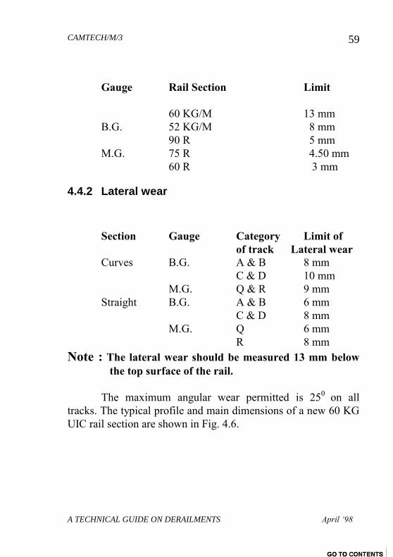
Gauge Rail Section Limit
60 KG/M 13 mm
B.G. 52 KG/M 8 mm
90 R 5 mm
M.G. 75 R 4.50 mm
60 R 3 mm
4.4.2 Lateral wear
Section Gauge Category Limit of
of track Lateral wear
Curves B.G. A & B 8 mm
C & D 10 mm
M.G. Q & R 9 mm
Straight B.G. A & B 6 mm
C & D 8 mm
M.G. Q 6 mm
R 8 mm
Note : The lateral wear should be measured 13 mm below
the top surface of the rail.
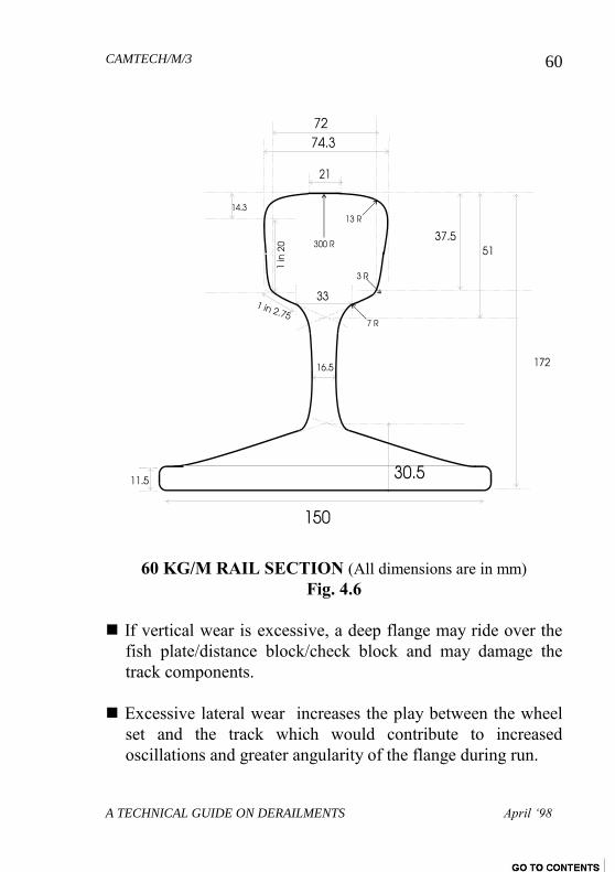
The maximum angular wear permitted is 250
on all
tracks. The typical profile and main dimensions of a new 60 KG
UIC rail section are shown in Fig. 4.6.
CAMTECH/M/3
A TECHNICAL GUIDE ON DERAILMENTS April ‘98
60
60 KG/M RAIL SECTION (All dimensions are in mm)
Fig. 4.6
If vertical wear is excessive, a deep flange may ride over the
fish plate/distance block/check block and may damage the
track components.
Excessive lateral wear increases the play between the wheel
set and the track which would contribute to increased
oscillations and greater angularity of the flange during run.
CAMTECH/M/3
A TECHNICAL GUIDE ON DERAILMENTS April ‘98
61
The angular wear is most critical. Angular wear is invariably
encountered on the outer rails on sharp curves as well as on
turn outs. If angular wear is excessive, the rail presents an
inclined plain to the wheel on which the flange may slide
upwards.
4.5 GAUGE
The distance between the two running edges of left and
right rails is known as Gauge (Fig. 4.8). It is 1676 mm on B.G.
The irregularity in gauge leads to excessive sinusoidal motions
of the vehicle leading to development of attack of wheel flange
with the rail. If gauge is found less than 1676 mm, it is termed as
Tight Gauge. If the gauge is more then 1676 mm, then it is
termed as Slack Gauge.
4.5.1 Effect Of Tight Or Slack Gauge
Due to slackness in gauge, play between flange and
running edge of the rail increases. Thus excessive slackness
further increases lateral oscillations, hunting, excessive flange
forces and angularity due to which the wheel may drop. The
main indication of slack gauge is that either one wheel remains
on the track and the other drops inside the track or both wheels
drop inside the track.
4.5.2 Tight Gauge
Tight gauge increases the strain on track fastenings and
creates a tendency for the wheel to lift on run. Due to tight
gauge, the flange of the wheel starts grinding against the rail
edge. This condition causes high flange forces to occur and the
flange ultimately mounts over the rail.
CAMTECH/M/3
A TECHNICAL GUIDE ON DERAILMENTS April ‘98
62
4.5.3 Causes Of Gauge Distortion
The following are the major causes of gauge distortion :
Worn out fastenings due to which track could not hold
the correct gauge.
Damaged sleepers and unserviceable sleepers due to
which fastening become loose.
Fastening not properly secured and becoming loose
due to high speed vibrations.
Missing fastenings i.e. keys, dogspikes etc.
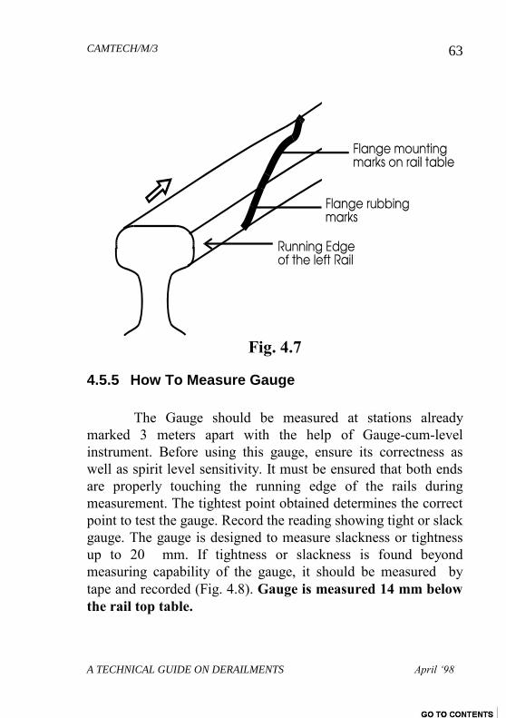
4.5.4 MARKING STATIONS FOR TRACK MEASUREMENTS
For investigating the cause of derailment, various
measurements pertaining to track are required to be taken
carefully. Before starting the measurements, point of mount or
drop has to be ascertained jointly by nominated supervisors
since the point of mount or drop is taken as reference point for
many measurements (Fig. 4.7). From the point of mount/drop,
stations are to be marked on the rail table at a interval of 3
meters on either side of the track up to a distance of 45 meters.
Hence 15 such stations are to be marked if the cause of -
derailment is normal. However if the cause is abnormal, as many
as 30 stations at the rear of the point of mount/drop can be
marked covering a distance of 90 meters if necessary. After
completing this work, measurements with regard to track should
be recorded from one end.
CAMTECH/M/3
A TECHNICAL GUIDE ON DERAILMENTS April ‘98
63
Fig. 4.7
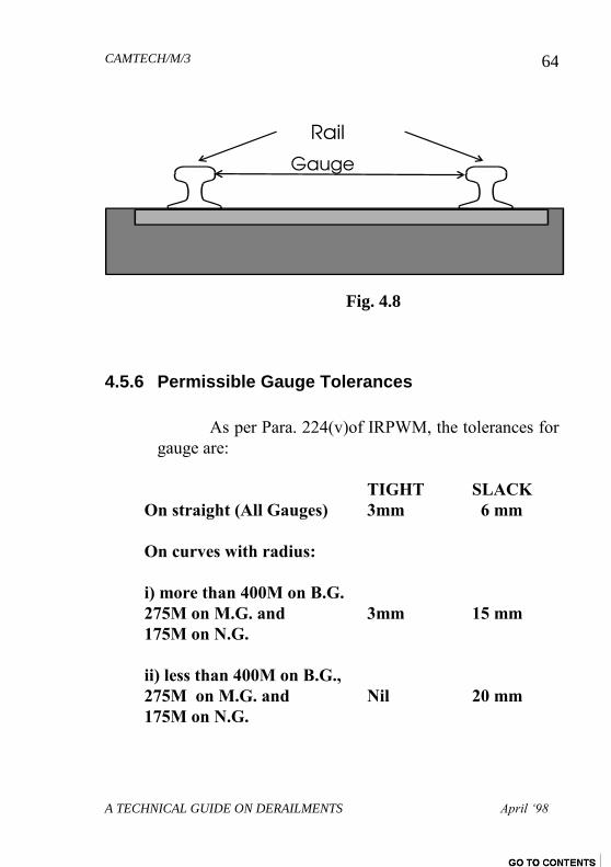
4.5.5 How To Measure Gauge
The Gauge should be measured at stations already
marked 3 meters apart with the help of Gauge-cum-level
instrument. Before using this gauge, ensure its correctness as
well as spirit level sensitivity. It must be ensured that both ends
are properly touching the running edge of the rails during
measurement. The tightest point obtained determines the correct
point to test the gauge. Record the reading showing tight or slack
gauge. The gauge is designed to measure slackness or tightness
up to 20 mm. If tightness or slackness is found beyond
measuring capability of the gauge, it should be measured by
tape and recorded (Fig. 4.8). Gauge is measured 14 mm below
the rail top table.
CAMTECH/M/3
A TECHNICAL GUIDE ON DERAILMENTS April ‘98
64
Fig. 4.8
4.5.6 Permissible Gauge Tolerances
As per Para. 224(v)of IRPWM, the tolerances for
gauge are:
TIGHT SLACK
On straight (All Gauges) 3mm 6 mm
On curves with radius:
i) more than 400M on B.G.
275M on M.G. and 3mm 15 mm
175M on N.G.
ii) less than 400M on B.G.,
275M on M.G. and Nil 20 mm
175M on N.G.

CAMTECH/M/3
A TECHNICAL GUIDE ON DERAILMENTS April ‘98
65
4.6 CROSS LEVEL
The relative difference in the height of left and right rail
at a given point on the track is known as Cross Level (on
straight track). The fluctuating cross level differences in the
track result in track Buckling (Para. 4.9) and help in developing
undesirable oscillations on vehicles adversely affecting their
stable running.
4.6.1 Effect of Variation in Cross Levels
Due to variation in Cross Levels, either one wheel is
above or below the plane of other wheels of the vehicle. If one
rail is higher, the wheel on that spot will be on a higher plane
and will cause off-loading of that wheel. On the other hand, if
one rail is lower, the wheel on that spot will be on a lower plane
and will cause off-loading of the opposite wheel. Thus variation
in cross levels affects the stability.
A uniform cross level difference does not matter much
from the point of derailment. A cant deficiency up to 75 mm is
normally permitted. If cross level differences up to this extent
are uniformly available over long stretches in the track, it may
not lead to unstable conditions. However the variations in cross
level called Twist are very important from safety point of view.
If the cross levels vary too frequently, the effect is the same as
difference in camber of springs and this may lead to derailments.
This effect is more pronounced in case of a four wheeler stock in
which one of the wheel tends to float due to excessive twist and
may get derailed.
CAMTECH/M/3
A TECHNICAL GUIDE ON DERAILMENTS April ‘98
66
Cross level is an important factor to be considered in
derailments and it should be recorded very carefully. Cross level
should be recorded taking left rail as the reference rail i.e.
recording whether the right rail is low or high. Normally cross
levels are measured from the point of mount or drop up to 45
meters on either side. Where point of mount is not clear, 90
meters in rear and 45 meters ahead may be taken for
measurement. The readings are essentially recorded from sleeper
to sleeper.
4.6.2 How to Measure Cross Levels
For measuring cross level, modified RDSO gauge is used
which records Gauge as well as Cross Levels simultaneously.
For measuring cross level, a good quality of spirit level is used
and is kept at the centre of the gauge. Before using spirit level,
the sensitivity should be checked i.e. whether the bubble is
freely moving in the cage or not. In the gauge, space is provided
for spirit level which slides freely on the gauge. The sliding
portion is calibrated on either side with which the difference in
cross level in mm can be read directly . If spirit level moves 10
mm to the right of the gauge, it indicates that right side rail is
lower by 10 mm as compared to the left rail . If spirit level
moves left side then this indicates that left rail is lower than right
rail. For measuring the cross levels, always take left rail as
reference rail and it should be clearly mentioned i.e. left rail is
low or high. Though maximum permissible variations in cross
level have not been laid down , a 13 mm variation in cross
levels at stations 3 meter apart is considered limiting value. -
Railway Board vide letter no 63/wg/tk/10 dated 10.11.64 has
laid down following tolerances for B.G. (see Table 4.1)
CAMTECH/M/3
A TECHNICAL GUIDE ON DERAILMENTS April ‘98
67
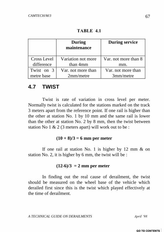
TABLE 4.1
During
maintenance
During service
Cross Level
difference
Variation not more
than 4mm
Var. not more than 8
mm.
Twist on 3
metre base
Var. not more than
2mm/metre
Var. not more than
3mm/metre
4.7 TWIST
Twist is rate of variation in cross level per meter.
Normally twist is calculated for the stations marked on the track
3 meters apart from the reference point. If one rail is higher than
the other at station No. 1 by 10 mm and the same rail is lower
than the other at station No. 2 by 8 mm, then the twist between
station No 1 & 2 (3 meters apart) will work out to be :
(10 + 8)/3 = 6 mm per meter
If one rail at station No. 1 is higher by 12 mm & on
station No. 2, it is higher by 6 mm, the twist will be :
(12-6)/3 = 2 mm per meter
In finding out the real cause of derailment, the twist
should be measured on the wheel base of the vehicle which
derailed first since this is the twist which played effectively at
the time of derailment.
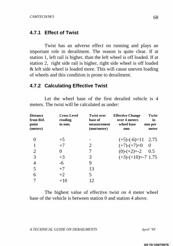
CAMTECH/M/3
A TECHNICAL GUIDE ON DERAILMENTS April ‘98
68
4.7.1 Effect of Twist
Twist has an adverse effect on running and plays an
important role in derailment. The reason is quite clear. If at
station 1, left rail is higher, than the left wheel is off loaded. If at
station 2, right side rail is higher, right side wheel is off loaded
& left side wheel is loaded more. This will cause uneven loading
of wheels and this condition is prone to derailment.
4.7.2 Calculating Effective Twist
Let the wheel base of the first derailed vehicle is 4
meters. The twist will be calculated as under:
Distance Cross Level Twist over Effective Change Twist
from Ref. reading base of over 4 meters in
point in mm. measurement wheel base mm per
(meters) (mm/meter) mm meter
0 +5 - (+5)-(-6)=11 2.75
1 +7 2 (+7)-(+7)=0 0
2 0 7 (0)-(+2)=-2 0.5
3 +3 3 (+3)-(+10)=-7 1.75
4 -6 9
5 +7 13
6 +2 5
7 +10 12
The highest value of effective twist on 4 meter wheel
base of the vehicle is between station 0 and station 4 above.
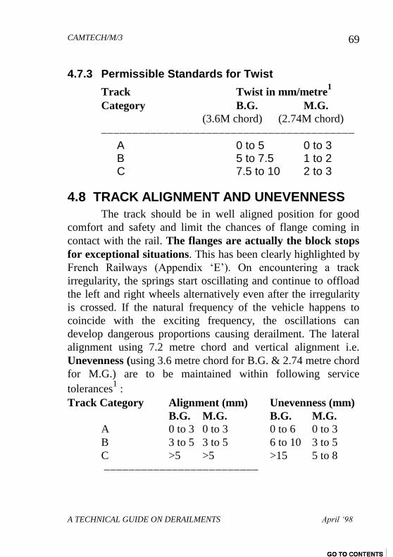
CAMTECH/M/3
A TECHNICAL GUIDE ON DERAILMENTS April ‘98
69
4.7.3 Permissible Standards for Twist
Track Twist in mm/metre1
Category B.G. M.G.
(3.6M chord) (2.74M chord) A 0 to 5 0 to 3 B 5 to 7.5 1 to 2 C 7.5 to 10 2 to 3
4.8 TRACK ALIGNMENT AND UNEVENNESS
The track should be in well aligned position for good
comfort and safety and limit the chances of flange coming in
contact with the rail. The flanges are actually the block stops
for exceptional situations. This has been clearly highlighted by
French Railways (Appendix „E‟). On encountering a track
irregularity, the springs start oscillating and continue to offload
the left and right wheels alternatively even after the irregularity
is crossed. If the natural frequency of the vehicle happens to
coincide with the exciting frequency, the oscillations can
develop dangerous proportions causing derailment. The lateral
alignment using 7.2 metre chord and vertical alignment i.e.
Unevenness (using 3.6 metre chord for B.G. & 2.74 metre chord
for M.G.) are to be maintained within following service
tolerances1 :
Track Category Alignment (mm) Unevenness (mm)
B.G. M.G. B.G. M.G.
A 0 to 3 0 to 3 0 to 6 0 to 3
B 3 to 5 3 to 5 6 to 10 3 to 5
C >5 >5 >15 5 to 8
CAMTECH/M/3
A TECHNICAL GUIDE ON DERAILMENTS April ‘98
70
1 Ministry of Railways, Government of India. Investigation of derailments.
(Pune: Indian Railway Institute of Civil Engineering,1995), p. 22.
4.9 CREEP
The longitudinal movement of rails in the track is called
Creep. Creep on the rails vary from place to place. In some
places it may be as much as few centimetres in a month whereas
at some other location, it may be negligible.
Due to creeping of rails, the openings in the rail joints at
the point of creep gets widened.
4.9.1 Causes of Creep
Many theories have been evolved to explain the reasons
for creeping of rails in a track. Some are explained as below.
A. Wave Theory
According to this theory, a moving train sets up a
wave motion in the resilient track portion of the rail.
Immediately under the wheels of the train, the rails between
adjacent sleepers get depressed or deflected somewhat due to
vertical loading. The moving wheel pushes the elevated portion
of the wave, which in turn forces the rail in the direction of
traffic. The raised portion of the rail in front of the moving load
is carried forward by the wheel and this helps in developing
creep. The raised portion of the rail at the rear of the moving
wheel then assumes its normal position.
Along with the moving wheels of the train, the
CAMTECH/M/3
A TECHNICAL GUIDE ON DERAILMENTS April ‘98
71
depressions formed in the rail also moves with them. As soon as
the loaded wheels pass over a depression, the portion of the rail
springs back to its original level. In this way, the wave motion
tends to move along the entire length forward with the moving
train. Similarly the impact of several wheels at a rail joint also
causes creep.
The pitch and depth of the wave in the track however
depends upon the following factors :
Stiffness of the track
Spacing of the sleepers
Wheel base of the vehicles
Weight of the rails quantity and quality of the ballast
Standard of the maintenance of the track
Track modulus of the material.
To reduce the creep, it should be ensured that the track
possesses the following qualities :
Increased stiffness
Stable soil for formation
Angular ballast for better interlocking
B. Change of Temperature Theory
Development of creep rail may be caused by
expansion/contraction of rails due to change in temperature. The
change in temperature depends upon the range of temperature
and the location of the track i.e.. whether the portion is exposed
to sun or remains under shade. Creep is more rapid during hot
CAMTECH/M/3
A TECHNICAL GUIDE ON DERAILMENTS April ‘98
72
summer as compared to cold winters
C. Unbalanced Traffic Theory According to this theory, if heavy traffic moves in one
direction and light traffic moves in opposite direction
predominantly on a single line track, unequal creeping occurs
between the two directions. The net effect of creep in the
direction of movement of heavier traffic is more. In case of
double line tracks , the movement of trains is more or less
unidirectional and as such creep develops in both the tracks in
the direction of movements of trains.
Besides the above theories, the creep may also develop
due to the following factors :
1. Loose fittings of rails
2. Bad quality of sleepers
3. Bad alignment of curves
4. Too tight or too slack gauge
5. Gradient of the track
6. Life of the rails
7. Uneven spacing of the sleepers
8. High embankments.
9. Weight of the rails.
In fact, it is very difficult to predict the magnitude of
creep. Some times, only one of the rails may also start creeping
in a direction opposite to the other rail
CAMTECH/M/3
A TECHNICAL GUIDE ON DERAILMENTS April ‘98
73
4.9.2 Effect of creep
Though there are several serious effects of creep, the
most serious is buckling of the track. If proper attention is not
paid, a buckled track may easily derail a train. The other harmful
effects are as under :
The sleepers move out of square and position.
The gauge and alignment of the track gets disturbed.
The surface of the rails get disturbed considerably due to
movement of sleepers from their packed loads. This causes
uncomfortable riding .
Rail joints at the starting points of the creep get opened out of
their permissible limit considerably. The stresses develop in
the fish plates and bolts. This may sometimes break the fish
bolts and the rail ends gets battered badly. At the point where
creep ends, the rail joint gets jammed and thus prevents free
expansion of the rail.
Points and crossings get disturbed and it becomes difficult to
maintain the correct gauge and alignment. The movement of
switches becomes difficult and even the interlocking
arrangement is thrown out of gear.
The expansion gaps become either too big or too short.
Besides above defects, kinking of rails forcing the ballast and
even smashing the fish plates and fish bolts are common
CAMTECH/M/3
A TECHNICAL GUIDE ON DERAILMENTS April ‘98
74
occurrences due to creep.
4.9.3 Measurement Of Creep
The measurements of creep in a track may be done in the
field as explained below :
A. Fix two creep indication posts or unserviceable rail
pieces on either side of the track in the formation such
that their tops are about 25 mm above the rail level.
B. Fasten a string to the tops of the posts such that it passes
freely below the rail bottom.
C. Make a chisel mark or a point mark on the side of bottom
flange of the rail on either side of the track. Note down
the time and date of marking .
D. After a particular interval of time, measure the distance
between the chisel marks and the string. This distance is
the required amount of creep which has developed
during the given time interval .
4.9.4 Remedial Steps against Creep
The following precautions are required to be taken to
prevent and reduce the creep of rails in the track :
A. Keep the sleepers always well packed with heavy angular
ballast and provide wide shoulders as to resist the
CAMTECH/M/3
A TECHNICAL GUIDE ON DERAILMENTS April ‘98
75
movement of the sleepers.
B. Keep all the rail joints levelled so that there are less
chances of impact by the moving wheels .
C. Keep the fish bolts tight and oil them frequently so that the
ends of the rails move freely under thermal stresses.
D. Provide anti-creepers or anchors on the top of sound
sleepers. If the creep still continues, the number of anchors
may be increased per rail panel.
4.9.5 Track Maintenance against Excessive Creep
The maximum permissible limit of creep is 150 mm. In
case the creep exceeds this limit, the adjustments must be made
as under :
A. Measure the expansion gaps and check against the total
amount of gap in the length which should be equal to the
standard expansion gap required at the given temperature
multiplied by the number of joints in the rail panel.
B. Remove the keys and fish plates. Insert correct expansion
liners before pulling the rail back with bars.
C. Tighten up the fish plates and insert key properly.
D. In case the total gap is more than the standard gap, the
required closure rails may be used with a speed restriction
of 30 Km/h till the gaps are removed.
CAMTECH/M/3
A TECHNICAL GUIDE ON DERAILMENTS April ‘98
76
E. While adjusting the creep, the sleeper spacing should also be
adjusted.
4.9.6 Track Lengths susceptible to Creep
The locations in track more susceptible to creep are :
Steel sleeper trackCST-9 sleeper track joining the
wooden sleeper track.
Long stretches on gradients having dips
Approaches to major girder bridges or other stable
structures.
Approaches to level crossings and points & crossings.
4.10 BUCKLING OF TRACK
Buckling of track occurs when very high compressive
forces are created in the rails. A special watch should be kept at
the junction of two stretches of track where one is liable to creep
and the other is held against creep. Some of the examples are:
Track laid on wooden sleepers with inadequate anchors
and scanty ballast.
Track laid on metal sleepers with loose keys butting
against the track laid on new sleepers with tight
CAMTECH/M/3
A TECHNICAL GUIDE ON DERAILMENTS April ‘98
77
fastening.
Track anchored with welded track.
As one side of such a junction point is held firmly, the
movement of rails due to creep from the other side is restricted
resulting in heavy compressive forces being exerted. This will
tend to buckle the track. Jammed rail joints are therefore an
indication of the track being subjected to undue strain which
may result in track buckling.
4.10.1 Conditions inducing Buckling
The following conditions create high compressive forces
in the rail:
Inadequate expansion gaps
Failure to counter act creep in time
Non lubrication of rail joints
Failure to remove rail closures from track
4.10.2 Precaution against Buckling
A. Greasing of fish plates should be done before the hot
weather sets in.
B. The joints gape survey is done in the case of SWR and
adjusted before the hot weather.
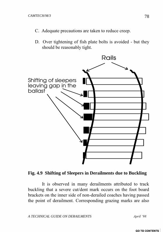
CAMTECH/M/3
A TECHNICAL GUIDE ON DERAILMENTS April ‘98
78
C. Adequate precautions are taken to reduce creep.
D. Over tightening of fish plate bolts is avoided - but they
should be reasonably tight.
Fig. 4.9 Shifting of Sleepers in Derailments due to Buckling
It is observed in many derailments attributed to track
buckling that a severe cut/dent mark occurs on the foot board
brackets on the inner side of non-derailed coaches having passed
the point of derailment. Corresponding grazing marks are also
CAMTECH/M/3
A TECHNICAL GUIDE ON DERAILMENTS April ‘98
79
found available on the top sole plate of the bogies. Another
indication is the shifting of sleepers towards one side from their
original position leaving gaping holes in the ballast (Fig. 4.9).
CHAPTER 5
DERAILMENT ON CURVES
The rolling stock has higher chances of derailing on a
curved track since the flange is almost continuously pressing
against the running edge of outer rail in addition to the normal
tread contact with the rail. The analysis made on mid-section
derailments on Central Railway reveals that the number of
derailments are much higher on curved alignments compared to
straight track. It is therefore essential to pay utmost attention to
proper maintenance of curved tracks.
5.1 ADVERSE FACTORS ON A CURVE
The curved track has higher chances of developing
following adverse conditions:
Excessive angular wear on the outer rail
Excessive flattening of head on the inner rail
Fracture and failure of rails
Gauge widening
Track distortion
CAMTECH/M/3
A TECHNICAL GUIDE ON DERAILMENTS April ‘98
80
5.1.1 Vehicles entering a curve at speeds higher than
maximum permissible speed may cause distortion of the track or
lead to mounting of wheel over the outer rail. Wheel mounting
on the inner rail is also possible in case of sudden braking
causing bunching of vehicles.
5.1.2 The outer rails on curves also suffer higher angular wear
which may present a convenient inclined plane for the wheel to
slide up.
5.1.3 Similarly a wagon stopping on a sharp curve with high
superelevation (Para. 5.2) causes the outer wheels to get off-
loaded. When the wagon starts moving even at crawling speed,
the guiding force acting on the outer leading wheel is
significantly more as higher force is needed to turn the vehicle
and follow the curved path. The Y/Q ratio for the outer leading
wheel thus becomes higher and the wheel may mount the rail if
it exceeds the critical limit.
5.2 CANT or SUPERELEVATION
When a vehicle moves on a circular curve, it is subjected
to a constant radial acceleration which produces a centrifugal
force acting away from the centre in a radial direction. The value
of this centrifugal force is given by the formula :
F = WV2/ GR
Where :
F - Centrifugal force in tons
W - Weight of the vehicle in tons.
V - Speed in feet /sec
CAMTECH/M/3
A TECHNICAL GUIDE ON DERAILMENTS April ‘98
81
G - Acceleration due to gravity in feet / sec2
R - Radius of the curve in feet
To counter this centrifugal force, outer rail on the curves
is kept little higher than the inner rail. The inner rail is normally
maintained at its original level and considered as a reference rail.
Raising of outer rail on curve to a specified height in this fashion
is known as Cant or Superelevation. The state of equilibrium
reaches when both the wheels bear equally on the rails. In this
state of equilibrium, the level difference between outer and inner
rail on the curve is called equilibrium super elevation. The
equilibrium super elevation is given by :
e = GV2 / gR
In metric system : e = GV2 /127R
where:
e- Equilibrium super elevation
G- Gauge + Width of rail head in mm
V- Velocity
R- Radius of the curve
Note : The cant for each curve is normally indicated on the web
of inside face of inner rail to the nearest 5mm.
5.2.1 Reasons for providing Superelevation
To have a better distribution of load on two rails.
To reduce wear and tear of rails and rolling stock.
CAMTECH/M/3
A TECHNICAL GUIDE ON DERAILMENTS April ‘98
82
To neutralise the effect of lateral forces.
To provide comfort to passengers.
5.2.2 Degree of Curve VS Radius of Curve
The degree of a curve (D) is the angle subtended by the
curve at its centre by a chord of 30.5 metres. The relationship
between radius and degree of a curve is given by the equation :
D = 1750R
Hence for : 1 deg. curve, R = 1750 meters
2 deg. curve, R = 875 meter
4 deg. curve, R = 438 meter and so on.
5.2.3 Effect of excessive or inadequate Cant
The maximum value of superelevation is approximately
1/10 to 1/12 of gauge. The values of maximum superelevation
prescribed on Indian Railways are given below in Table 5.1.
(Para. 406 of IRPWM)
Table 5.1
Gauge Track Group Max. cant in mm
B.G. A,B,C 165
D & E 140
M.G. All Groups 90 (100 with
CAMTECH/M/3
A TECHNICAL GUIDE ON DERAILMENTS April ‘98
83
special permission
of C.E.)
N.G. (762mm) All 65 (75 with special
permission of C.E.)
It is very important to provide super elevation suiting the
degree of curve.If super elevation is less, there is a possibility of:
Outer rail getting worn out as it will have to bear more strain
due to tendency of wheels to move away from the centre of
the curve under the influence of centrifugal forces.
The fast moving trains will have more lateral oscillations
causing discomfort to travelling public.
On the other hand, excessive super-elevation has these effects:
Inner rail will have to bear maximum strain and there is every
possibility of this rail giving way due to excessive strain and
cause gauge widening.
Due to excessive super elevation, there is every possibility of
slow moving goods trains getting derailed
Thus keeping in view the maximum permissible speed of
the section and the volume of goods traffic moving over the
section, a compromise has to be made which permits fast
moving trains to traverse safely and without discomfort to
passengers while permitting slow moving trains without risk of
derailments. This is the purpose for which cant deficiency is
provided.
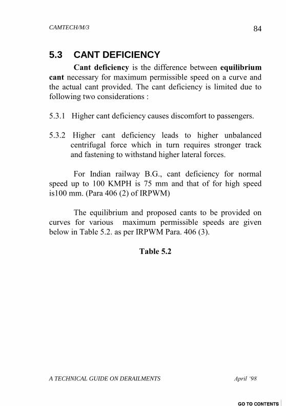
CAMTECH/M/3
A TECHNICAL GUIDE ON DERAILMENTS April ‘98
84
5.3 CANT DEFICIENCY
Cant deficiency is the difference between equilibrium
cant necessary for maximum permissible speed on a curve and
the actual cant provided. The cant deficiency is limited due to
following two considerations :
5.3.1 Higher cant deficiency causes discomfort to passengers.
5.3.2 Higher cant deficiency leads to higher unbalanced
centrifugal force which in turn requires stronger track
and fastening to withstand higher lateral forces.
For Indian railway B.G., cant deficiency for normal
speed up to 100 KMPH is 75 mm and that of for high speed
is100 mm. (Para 406 (2) of IRPWM)
The equilibrium and proposed cants to be provided on
curves for various maximum permissible speeds are given
below in Table 5.2. as per IRPWM Para. 406 (3).
Table 5.2
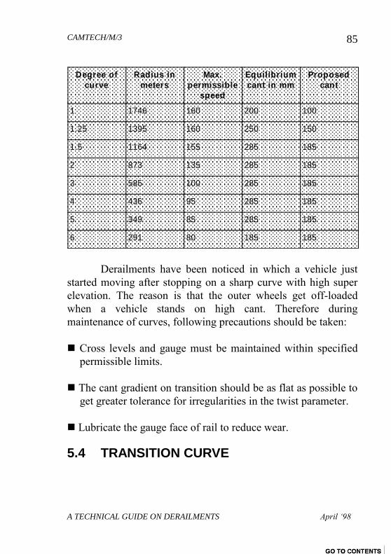
CAMTECH/M/3
A TECHNICAL GUIDE ON DERAILMENTS April ‘98
85
Degree of
curve
Radius in
meters
Max.
permissible
speed
Equilibrium
cant in mm
Proposed
cant
1 1746 160 200 100
1.25 1395 160 250 150
1.5 1164 155 285 185
2 873 135 285 185
3 585 100 285 185
4 436 95 285 185
5 349 85 285 185
6 291 80 185 185
Derailments have been noticed in which a vehicle just
started moving after stopping on a sharp curve with high super
elevation. The reason is that the outer wheels get off-loaded
when a vehicle stands on high cant. Therefore during
maintenance of curves, following precautions should be taken:
Cross levels and gauge must be maintained within specified
permissible limits.
The cant gradient on transition should be as flat as possible to
get greater tolerance for irregularities in the twist parameter.
Lubricate the gauge face of rail to reduce wear.
5.4 TRANSITION CURVE
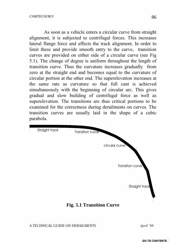
CAMTECH/M/3
A TECHNICAL GUIDE ON DERAILMENTS April ‘98
86
As soon as a vehicle enters a circular curve from straight
alignment, it is subjected to centrifugal forces. This increases
lateral flange force and affects the track alignment. In order to
limit these and provide smooth entry to the curve, transition
curves are provided on either side of a circular curve (see Fig
5.1). The change of degree is uniform throughout the length of
transition curve. Thus the curvature increases gradually from
zero at the straight end and becomes equal to the curvature of
circular portion at the other end. The superelevation increases at
the same rate as curvature so that full cant is achieved
simultaneously with the beginning of circular arc. This gives
gradual and slow building of centrifugal force as well as
superelevation. The transitions are thus critical portions to be
examined for the correctness during derailments on curves. The
transition curves are usually laid in the shape of a cubic
parabola.
Fig. 5.1 Transition Curve
CAMTECH/M/3
A TECHNICAL GUIDE ON DERAILMENTS April ‘98
87
5.4.1 Length of Transition Curve
The length of transition portion depends upon the degree
of curve, max. permissible speed, amount of superelevation and
the rate at which the cant is run off. The desirable length of
transition curve in meters is maximum of following three values
(1) 0.008 Ca*Vm
(2) 0.008 Cd * Vm
(3) 0.72 Ca
Where Ca is actual cant provided in mm, Cd is cant
deficiency in mm and Vm is maximum permissible speed in
Kmph. In exceptional cases where enough space is not available,
length should be maximum of these values : 2/3 of (1), 2/3 of
(2) and 1/2 of (3) above.
5.5 VERSINE
Versine is the perpendicular distance measured in mm
from the centre of the chord line to the arc between two marked
stations (Fig 5.2).
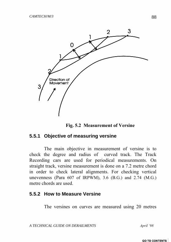
CAMTECH/M/3
A TECHNICAL GUIDE ON DERAILMENTS April ‘98
88
Fig. 5.2 Measurement of Versine
5.5.1 Objective of measuring versine
The main objective in measurement of versine is to
check the degree and radius of curved track. The Track
Recording cars are used for periodical measurements. On
straight track, versine measurement is done on a 7.2 metre chord
in order to check lateral alignments. For checking vertical
unevenness (Para 607 of IRPWM), 3.6 (B.G.) and 2.74 (M.G.)
metre chords are used.
5.5.2 How to Measure Versine
The versines on curves are measured using 20 metres
CAMTECH/M/3
A TECHNICAL GUIDE ON DERAILMENTS April ‘98
89
overlapping chords with stations at 10 metres intervals. For turn-
out and turn-in curves, versines to be measured every 1.5 metres
with overlapping chord of 6 meters (IRPWM Para. 401). A
fishing/nylon wire is stretched between two ends of the chord at
the inner edge of the outer rail. Care should be taken while
stretching the chord or wire to ensure that it is applied at the
running side of the rail at gauge point. The perpendicular
distance between the rail and the chord/wire at the middle point
of the chord is measured in mm which gives the value of versine
for the chord.
5.5.3 To determine the Degree of Curve with the help
of Versine
On a curved track, the versine in c.m. on a chord of 11.8
meters directly gives the degree of curve. Thus versine measured
in c.m. on a 6 meter chord gives approx. 1/4 of the degree of
curve and versine in cm. on a 3 meter chord gives approx. 1/16
of the degree of curve. Thus these values should be multiplied
by 4 and 16 respectively to arrive at the exact degree of curve.
CAMTECH/M/3
A TECHNICAL GUIDE ON DERAILMENTS April ‘98
89
CHAPTER 6
POINTS AND CROSSINGS
At railway stations and yards, a number of tracks are
provided for receipt and despatch of trains. When trains are
received or despatched, they have to cross other tracks and come
to the desired line. In this process, they pass over a number of
points and crossings.
A set of points and crossing consists of the following
main items:
6.1 Switch assembly
6.2 Crossing assembly
6.3 Lead rail joining switch and crossing assembly
6.1 SWITCH ASSEMBLY
A switch assembly consists of two tongue and two stock
rails. The stock rail is actually part of main rail while the tongue
rail has a tapered edge which sets against the stock rail so as to
set the route for the reception and despatch of train in the desired
direction. The inner or tapered edge of tongue rail is known as
Toe while the thicker edge is known as Heel of the tongue rail.
The toe of the tongue rail is tapered such that it doesn’t cause
any obstruction to the movement of wheels.
If length of tongue rail is less, the wheel weight on heel
causes the toe to jump upwards. This jumping of toe results in a
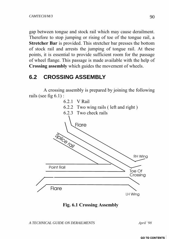
CAMTECH/M/3
A TECHNICAL GUIDE ON DERAILMENTS April ‘98
90
gap between tongue and stock rail which may cause derailment.
Therefore to stop jumping or rising of toe of the tongue rail, a
Stretcher Bar is provided. This stretcher bar presses the bottom
of stock rail and arrests the jumping of tongue rail. At these
points, it is essential to provide sufficient room for the passage
of wheel flange. This passage is made available with the help of
Crossing assembly which guides the movement of wheels.
6.2 CROSSING ASSEMBLY
A crossing assembly is prepared by joining the following
rails (see fig 6.1) :
6.2.1 V Rail
6.2.2 Two wing rails ( left and right )
6.2.3 Two check rails
Fig. 6.1 Crossing Assembly
CAMTECH/M/3
A TECHNICAL GUIDE ON DERAILMENTS April ‘98
91
6.3 IMPORTANT ASPECTS IN POINTS AND
CROSSING MAINTENANCE
Some important provisions of IRPWM Para. 237 are :
6.3.1 There should be no junction fish plates at the stock rail
joints (SRJ) or at the heel of crossing (HOC). At least
one rail on either of the points and crossing should be of
the same section as the Point and Crossing assembly rail
section.
6.3.2 At all places in a point and crossing, the gauge shall be
uniform except at point just ahead of the toe of the
switch where it will be slightly slack. (enough to house
the tip of the tongue rail)
6.3.3 Badly worn and damaged stock and tongue rails should
be replaced by serviceable ones .
6.3.4 Tongue rail may be classified as worn/damaged when
(IRPWM,1986 - Advance correction slip No 20 dated
16-11-98) ::
A. It is chipped/cracked over a length of 200 mm
within a distance of 1000 mm from its toe.
(i) chipped length will be the portion where
tongue rail has worn out for a depth of more than
10 mm over a continuous length of 10 mm.
B. It has developed knife edged tip (thickness of top
edge being less than 2 mm) over a length of more
CAMTECH/M/3
A TECHNICAL GUIDE ON DERAILMENTS April ‘98
92
than 100 mm any where up to a distance of 1000
mm from its toe.
C. It is badly twisted or bent and does not house
properly against the stock rail causing a gap of
more then 5 mm at the toe (the limit prescribed in
the I.R. Signal Engineering Manual.
The tongue rail can however be reused after
reconditioning of the broken tip, by welding and
rectification of the bend/twist by Jim crowing. It is also a
good practice to replace a tongue rail having a knife edge
tip as it is liable to break at that location.
The wear of the tongue rail ( measured at 13 to 15
mm below the top table of stock rail) shall not exceed the
following limits (IRPWM,1986 - Advance correction
slip No 20 dated 16-11-98) :
Vertical wear - 8 mm for 60 Kg
5 mm for 52 Kg and 90R
3 mm for 75R and 60R
Lateral wear - 8 mm for 60 Kg
6 mm for 52Kg and 90R
5 mm for 75R and 60R
6.3.5 Slight wide gauge at the toe of switch may be adjusted by
providing suitable steel packing between the web of the
stock rail and the lug of the slide chair.
CAMTECH/M/3
A TECHNICAL GUIDE ON DERAILMENTS April ‘98
93
6.3.6 If wing rails or check rails are badly worn laterally, it
could be due to wide gauge at the crossing. Gauge can be
maintained properly by the provision of a gauge tie plate
under the nose of the crossing, on lay out of wooden
sleepers.
6.3.7 In obtuse crossings, the distance between the throat and
the nose must be maintained correctly.
6.3.8 In a diamond crossing, obtuse crossing should be laid
square to each other with respect to centre line of the
acute crossing.
6.3.9 Maximum vertical wear on wing rail or nose of crossing
shall be 10 mm.
6.3.10 The curve lead should be laid by offsets from the gauge
face of the straight track. Stations at 1.5 meter intervals
should be marked and the versine checked and track
attended as necessary.
6.3.11 The versines of turn-in curves on loops should be
recorded at stations at 1.5 m intervals during inspection
of points and crossings to check the sharpness of the
curve and rectified as necessary. The turn-in curve
should be checked for the condition of sleepers and
fastenings.
6.3.12 There should be no change of cant between points 20
meters on B.G. and 15 meters on M.G. outside the toe of
CAMTECH/M/3
A TECHNICAL GUIDE ON DERAILMENTS April ‘98
94
switch and heel of crossing respectively, except in cases
where points and crossings have to be taken off from the
transition portion of a curve. In exceptional cases
however specific relaxation may be given by the Chief -
Engineer.
Any work involving the insertion or removal of
points and crossings on a running line must be carried
out only after obtaining the sanction of the -
Commissioner of Railway Safety.
PWI is responsible for the correct gauging of the
switches and SI will be responsible for the correct fixing
of the interlocking apparatus.
6.4 DERAILMENTS ON POINTS AND CROSSINGS
6.4.1 The derailments on points and crossings occur at
switches(points) which either gape initially or open
slightly under the passing wheels. Gaping points are
caused by a bent tongue rail and by wrongly adjusted
heel bolts. Any obstruction like a piece of stone will also
result in the switches not setting home. Although, on
carefully maintained interlocked points, an obstruction is
detected and proper closing of points is ensured, loss of
lever movement in the interlocking equipment will
permit pulling of lever even in the presence of such
obstruction. A frequent cause of defective points is their
being forced open in the trailing direction during
shunting operation. If the defect is not set right, the
switches will not close effectively and there will be a
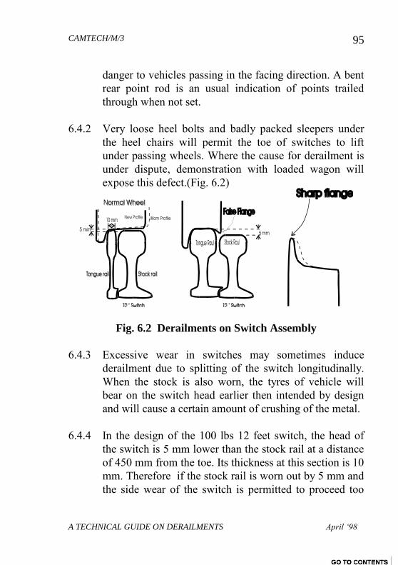
CAMTECH/M/3
A TECHNICAL GUIDE ON DERAILMENTS April ‘98
95
danger to vehicles passing in the facing direction. A bent
rear point rod is an usual indication of points trailed
through when not set.
6.4.2 Very loose heel bolts and badly packed sleepers under
the heel chairs will permit the toe of switches to lift
under passing wheels. Where the cause for derailment is
under dispute, demonstration with loaded wagon will
expose this defect.(Fig. 6.2)
Fig. 6.2 Derailments on Switch Assembly
6.4.3 Excessive wear in switches may sometimes induce
derailment due to splitting of the switch longitudinally.
When the stock is also worn, the tyres of vehicle will
bear on the switch head earlier then intended by design
and will cause a certain amount of crushing of the metal.
6.4.4 In the design of the 100 lbs 12 feet switch, the head of
the switch is 5 mm lower than the stock rail at a distance
of 450 mm from the toe. Its thickness at this section is 10
mm. Therefore if the stock rail is worn out by 5 mm and
the side wear of the switch is permitted to proceed too
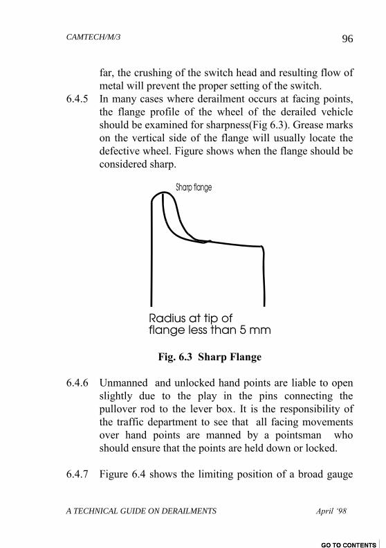
CAMTECH/M/3
A TECHNICAL GUIDE ON DERAILMENTS April ‘98
96
far, the crushing of the switch head and resulting flow of
metal will prevent the proper setting of the switch.
6.4.5 In many cases where derailment occurs at facing points,
the flange profile of the wheel of the derailed vehicle
should be examined for sharpness(Fig 6.3). Grease marks
on the vertical side of the flange will usually locate the
defective wheel. Figure shows when the flange should be
considered sharp.
Fig. 6.3 Sharp Flange
6.4.6 Unmanned and unlocked hand points are liable to open
slightly due to the play in the pins connecting the
pullover rod to the lever box. It is the responsibility of
the traffic department to see that all facing movements
over hand points are manned by a pointsman who
should ensure that the points are held down or locked.
6.4.7 Figure 6.4 shows the limiting position of a broad gauge
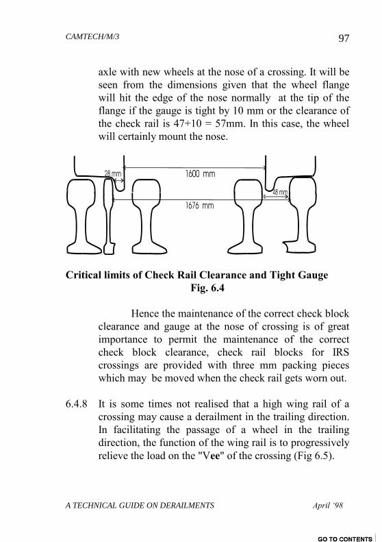
CAMTECH/M/3
A TECHNICAL GUIDE ON DERAILMENTS April ‘98
97
axle with new wheels at the nose of a crossing. It will be
seen from the dimensions given that the wheel flange
will hit the edge of the nose normally at the tip of the
flange if the gauge is tight by 10 mm or the clearance of
the check rail is 47+10 = 57mm. In this case, the wheel
will certainly mount the nose.
Critical limits of Check Rail Clearance and Tight Gauge
Fig. 6.4
Hence the maintenance of the correct check block
clearance and gauge at the nose of crossing is of great
importance to permit the maintenance of the correct
check block clearance, check rail blocks for IRS
crossings are provided with three mm packing pieces
which may be moved when the check rail gets worn out.
6.4.8 It is some times not realised that a high wing rail of a
crossing may cause a derailment in the trailing direction.
In facilitating the passage of a wheel in the trailing
direction, the function of the wing rail is to progressively
relieve the load on the "Vee" of the crossing (Fig 6.5).
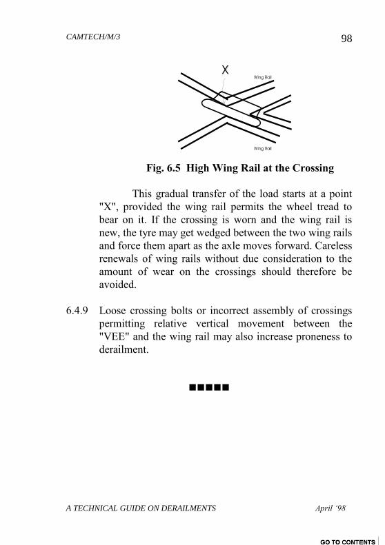
CAMTECH/M/3
A TECHNICAL GUIDE ON DERAILMENTS April ‘98
98
Fig. 6.5 High Wing Rail at the Crossing
This gradual transfer of the load starts at a point
"X", provided the wing rail permits the wheel tread to
bear on it. If the crossing is worn and the wing rail is
new, the tyre may get wedged between the two wing rails
and force them apart as the axle moves forward. Careless
renewals of wing rails without due consideration to the
amount of wear on the crossings should therefore be
avoided.
6.4.9 Loose crossing bolts or incorrect assembly of crossings
permitting relative vertical movement between the
"VEE" and the wing rail may also increase proneness to
derailment.
CAMTECH/M/3
A TECHNICAL GUIDE ON DERAILMENTS April ‘98
99
APPENDIX „A‟
PROFORMA
TO BE FILLED UP IN CASE OF DERAILMENT
DETAILS OF THE ACCIDENT
1. The relevant paras in this proforma are required to be
filled in by the inspectors/officers of the respective
department before leaving the site of the accident and
the complete proforma should be countersigned by
the senior most officer present at the site of accident.
2. This proforma should form a part of the proceedings
of the enquiry and should be sent along with the
proceedings.
THE SKETCH OF THE SITE OF ACCIDENT
The engineering representative should prepare
dimensioned sketches adequate for the preparation of
a scale plan covering the entire site of accident. In
preparing the sketch, due regard should be paid to the
following instructions :
1) The sketch giving train no., date and kilometre of site
of accident should be properly labelled.
CAMTECH/M/3
A TECHNICAL GUIDE ON DERAILMENTS April ‘98
100
2) The north point should be indicated.
3) It should indicate prominently the direction of the
movement and also the names of the stations in rear
and advance of the accident site.
4) It should cover a length of about 300 meters behind
the point of mount and almost and equal distance in
front.
5) Each track of the Permanent way must be denoted by
a pair of lines.
6) The position of level crossing, Telegraph post,
bridges, tunnels, Gradient posts with Gradient
Symbols, curves , demarking the beginning and end
giving details of degree of curvature prescribed,
super elevation and length of transition should be
indicated.
It should also indicate:
a) The position of all derailed vehicles and the marks
left by them either on sleepers, rails or ballast.
b) Point of Mounting with position of rail joints on
either side.
c) Point of Drop.
CAMTECH/M/3
A TECHNICAL GUIDE ON DERAILMENTS April ‘98
101
d) The pair of wheels of the first derailing vehicle.
e) The position in which every displaced rail/ wagon
or part of rail/ wagon and detachable components
were found.
f) In all the cases dimensions from nearest
kilometres post and centre line of track should be
given.
7. In case of accident within station limits sufficient
details about the station layout should be showed in
order to fully explain the movement of the effected
train in relation to the topography.
8. The distance of site of accident from permanent
structure to fix the site of accident precisely should
be indicated.
9. The distance should be indicated to show the extent
of the disturbance cause in P. Way or train
composition on account of the accident.
10. Any marks of sleeper or other track fittings should be
clearly indicated in their exact position in relation to the
track or vehicles.
11. Broken parts of other extraneous material, if found on
the site of accident, should be shown in the sketch, with
details giving their precise position in relation to track.
CAMTECH/M/3
A TECHNICAL GUIDE ON DERAILMENTS April ‘98
102
12. If necessary, more than one sketch should be enclosed
one clarifying the yard layout and the system of working
it and the other giving details, such as, position of wheels
marks etc. In the form, one line should be used to
represent both rails of track and such portion of the
station yard (in case of accidents within station limits)
should be covered as may be necessary. All necessary
details relevant to the issue must be embodied in the
sketch. The terminal station on the down side should be
mentioned on the right extremity of the sketch, the
terminal station on the upside being mentioned on the
left extremity. If the accidents takes place within station
limits the shorter sketch should be based on the station
working diagram.
13. Details of track structure should be shown in the sketch.
14. Details of damage to bridges involved, spanwise should
be shown.
15. In the case of accidents to and near level crossings, full
details of the level crossings should be furnished.
16. Any other details as may be considered necessary to
reconstruct the scene of the accident would also be
shown.
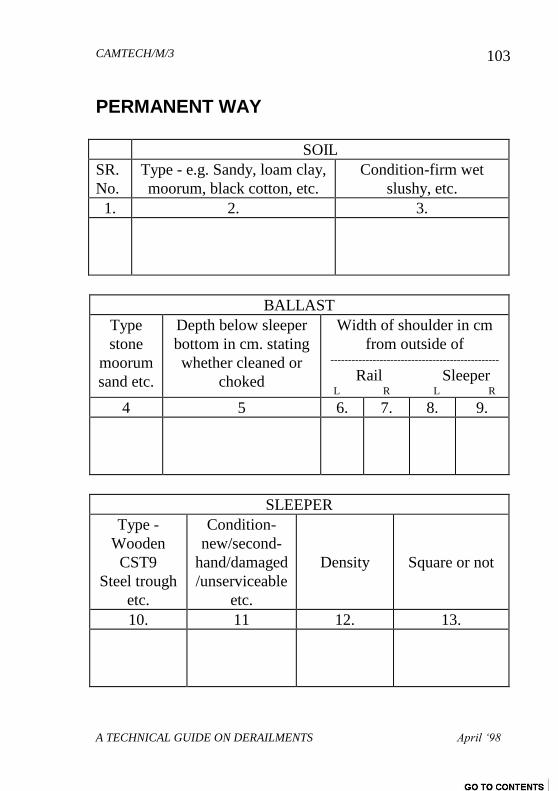
CAMTECH/M/3
A TECHNICAL GUIDE ON DERAILMENTS April ‘98
103
PERMANENT WAY
SOIL
SR.
No.
Type - e.g. Sandy, loam clay,
moorum, black cotton, etc.
Condition-firm wet
slushy, etc.
1. 2. 3.
BALLAST
Type
stone
moorum
sand etc.
Depth below sleeper
bottom in cm. stating
whether cleaned or
choked
Width of shoulder in cm
from outside of ------------------------------------------------
Rail Sleeper L R L R
4 5 6. 7. 8. 9.
SLEEPER
Type -
Wooden
CST9
Steel trough
etc.
Condition-
new/second-
hand/damaged
/unserviceable
etc.
Density
Square or not
10. 11 12. 13.
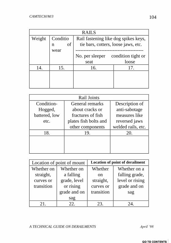
CAMTECH/M/3
A TECHNICAL GUIDE ON DERAILMENTS April ‘98
104
RAILS
Weight Conditio
n of
wear
Rail fastening like dog spikes keys,
tie bars, cotters, loose jaws, etc.
------------------------------------------
No. per sleeper condition tight or
seat loose
14. 15. 16. 17.
Rail Joints
Condition-
Hogged,
battered, low
etc.
General remarks
about cracks or
fractures of fish
plates fish bolts and
other components
Description of
anti-sabotage
measures like
reversed jaws
welded rails, etc.
18. 19. 20.
Location of point of mount Location of point of derailment
Whether on
straight,
curves or
transition
Whether on
a falling
grade, level
or rising
grade and on
sag
Whether
on
straight,
curves or
transition
Whether on a
falling grade,
level or rising
grade and on
sag
21. 22. 23. 24.
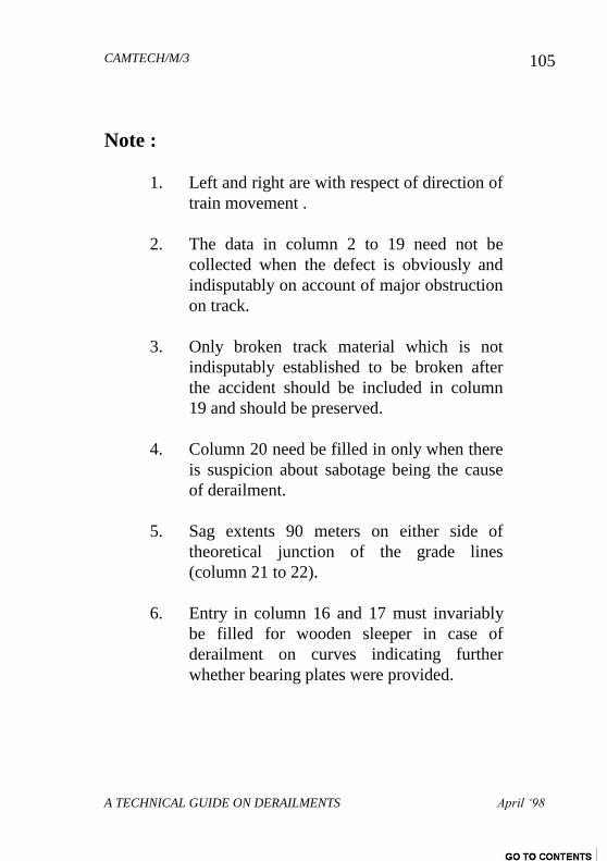
CAMTECH/M/3
A TECHNICAL GUIDE ON DERAILMENTS April ‘98
105
Note :
1. Left and right are with respect of direction of
train movement .
2. The data in column 2 to 19 need not be
collected when the defect is obviously and
indisputably on account of major obstruction
on track.
3. Only broken track material which is not
indisputably established to be broken after
the accident should be included in column
19 and should be preserved.
4. Column 20 need be filled in only when there
is suspicion about sabotage being the cause
of derailment.
5. Sag extents 90 meters on either side of
theoretical junction of the grade lines
(column 21 to 22).
6. Entry in column 16 and 17 must invariably
be filled for wooden sleeper in case of
derailment on curves indicating further
whether bearing plates were provided.
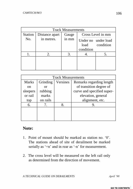
CAMTECH/M/3
A TECHNICAL GUIDE ON DERAILMENTS April ‘98
106
Track Measurements
Station
No.
Distance apart
in metres.
Gauge
in mm
Cross Level in mm ----------------------------------------------------------------------------
Under no under load
load condition
condition
1. 2. 3. 4. 5.
Track Measurements
Marks
on
sleepers
or rail
top
Grinding
or
rubbing
marks
on rails
Versines Remarks regarding length
of transition degree of
curve and specified super-
elevation, general
alignment, etc.
6. 7. 8. 9.
Note:
1. Point of mount should be marked as station no. ‘0’.
The stations ahead of site of derailment be marked
serially as ‘+n’ and in rear as ‘-n’ for measurement.
2. The cross level will be measured on the left rail only
as determined from the direction of movement.
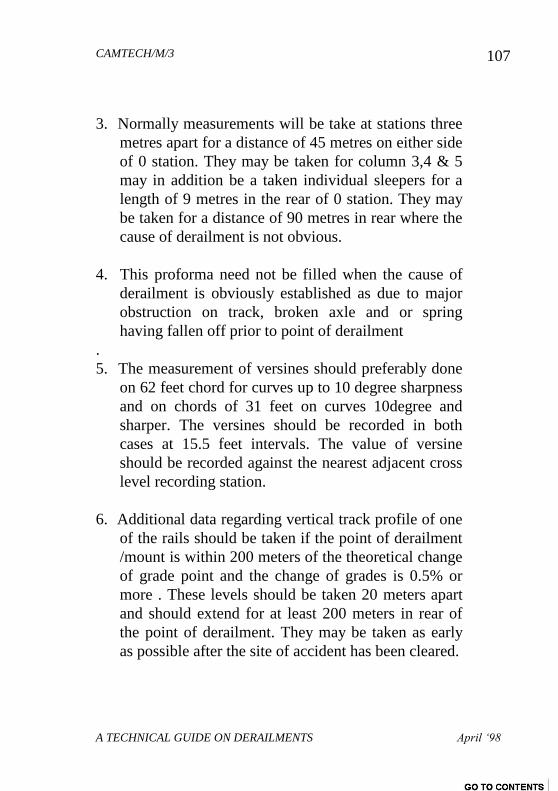
CAMTECH/M/3
A TECHNICAL GUIDE ON DERAILMENTS April ‘98
107
3. Normally measurements will be take at stations three
metres apart for a distance of 45 metres on either side
of 0 station. They may be taken for column 3,4 & 5
may in addition be a taken individual sleepers for a
length of 9 metres in the rear of 0 station. They may
be taken for a distance of 90 metres in rear where the
cause of derailment is not obvious.
4. This proforma need not be filled when the cause of
derailment is obviously established as due to major
obstruction on track, broken axle and or spring
having fallen off prior to point of derailment
.
5. The measurement of versines should preferably done
on 62 feet chord for curves up to 10 degree sharpness
and on chords of 31 feet on curves 10degree and
sharper. The versines should be recorded in both
cases at 15.5 feet intervals. The value of versine
should be recorded against the nearest adjacent cross
level recording station.
6. Additional data regarding vertical track profile of one
of the rails should be taken if the point of derailment
/mount is within 200 meters of the theoretical change
of grade point and the change of grades is 0.5% or
more . These levels should be taken 20 meters apart
and should extend for at least 200 meters in rear of
the point of derailment. They may be taken as early
as possible after the site of accident has been cleared.
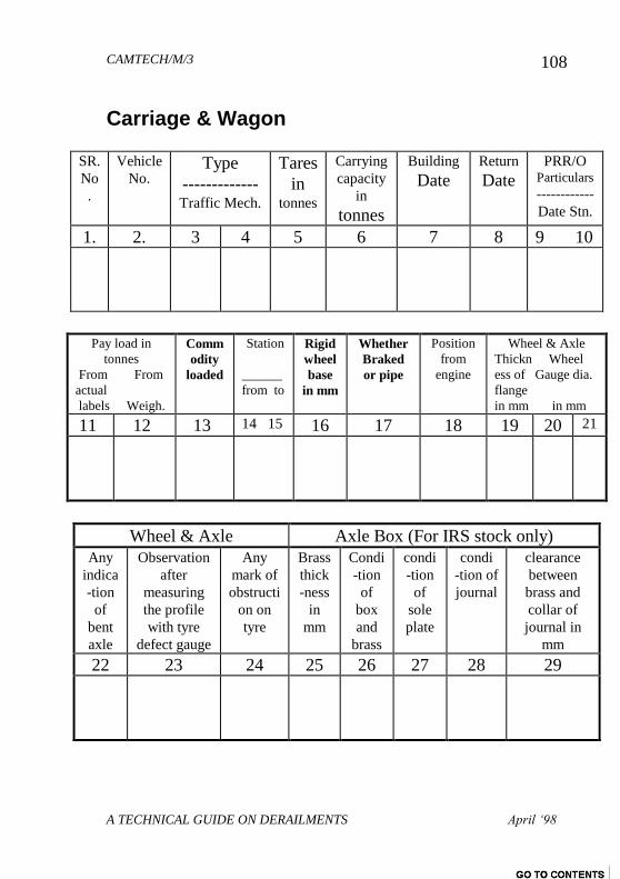
CAMTECH/M/3
A TECHNICAL GUIDE ON DERAILMENTS April ‘98
108
Carriage & Wagon
SR.
No
.
Vehicle
No. Type
------------- Traffic Mech.
Tares
in tonnes
Carrying
capacity
in
tonnes
Building
Date
Return
Date
PRR/O Particulars
------------
Date Stn.
1. 2. 3 4 5 6 7 8 9 10
Pay load in
tonnes
From From
actual
labels Weigh.
Comm
odity
loaded
Station
______
from to
Rigid
wheel
base
in mm
Whether
Braked
or pipe
Position
from
engine
Wheel & Axle
Thickn Wheel
ess of Gauge dia.
flange
in mm in mm
11 12 13 14 15 16 17 18 19 20 21
Wheel & Axle Axle Box (For IRS stock only)
Any
indica
-tion
of
bent
axle
Observation
after
measuring
the profile
with tyre
defect gauge
Any
mark of
obstructi
on on
tyre
Brass
thick
-ness
in
mm
Condi
-tion
of
box
and
brass
condi
-tion
of
sole
plate
condi
-tion of
journal
clearance
between
brass and
collar of
journal in
mm
22 23 24 25 26 27 28 29
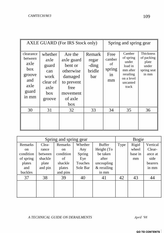
CAMTECH/M/3
A TECHNICAL GUIDE ON DERAILMENTS April ‘98
109
AXLE GUARD (For IRS Stock only) Spring and spring gear
clearance
between
axle
box
groove
and
axle
guard
in mm
whether
axle
guard
can
work
clear of
axle
box
groove
Are the
axle guard
bent or
otherwise
damaged
to prevent
free
movement
of axle
box
Remark
regar
-ding
bridle
bar
Free camber
of
spring
in
mm
Camber
of spring
under
load in
mm after
rerailing
on a level
uncanted
track
Thickness
of packing
plate
under
spring seat
in mm
30 31 32 33 34 35 36
Spring and spring gear Bogie Remarks
on
condition
of spring
plates
and
buckles
Clea-
rance
between
shackle
plate
and pin
Remarks
on
condition
of
shackle
plates
and pins
Whether
Any
Spring
Eye
Touches
Sole Bar
Buffer
Height (To
be taken
after
uncoupling
& rerailing
in mm
Type Rigid
wheel
base in
mm
Vertical
Clear-
ance at
side
bearers
in mm
37 38 39 40 41 42 43 44
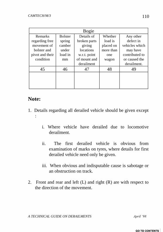
CAMTECH/M/3
A TECHNICAL GUIDE ON DERAILMENTS April ‘98
110
Bogie Remarks
regarding free
movement of
bolster and
pivot and their
condition
Bolster
spring
camber
under
load in
mm
Details of
broken parts
giving
locations
w.r.t. point
of mount and
derailment
Whether
load is
placed on
more than
one
wagon
Any other
defect in
vehicles which
may have
contributed to
or caused the
derailment.
45 46 47 48 49
Note:
1. Details regarding all derailed vehicle should be given except
:
i. Where vehicle have derailed due to locomotive
derailment.
ii. The first derailed vehicle is obvious from
examination of marks on tyres, where details for first
derailed vehicle need only be given.
iii. When obvious and indisputable cause is sabotage or
an obstruction on track.
2. Front and rear and left (L) and right (R) are with respect to
the direction of the movement.
CAMTECH/M/3
A TECHNICAL GUIDE ON DERAILMENTS April ‘98
111
3. For an obvious cause of derailment such as a broken axle,
spring dropping on run, or some part of under gear hanging
loose and causing obstruction. Only relevant particulars need
be filled.
4. For an obvious cause of derailment such as a broken axle,
spring dropping on the run, and/or some part of under gear
hanging loose and causing obstruction, only relevant
particulars need be filled.
5. The spring characteristics should also be got checked with a
load deflection testing machine in addition to filling
information under items, (46), (47), (48) and (49) of the
proforma.
TOOLS WHICH MUST BE AVAILABLE IN
ACCIDENT RELIEF TRAIN FOR TAKING
ABOVE MEASUREMENTS
For Track measurements :
1) Gauge-cum-Level
2) Stepped-Feeler-gauge set
3) Fish chord or nylon wire 10 meter
4) Steel scale 30 cm.
5) Straight edge 1.5 meter
6) Measuring tape - 20 Meter length

CAMTECH/M/3
A TECHNICAL GUIDE ON DERAILMENTS April ‘98
112
For Rolling Stock measurements :
1) Tyre Defect Gauge
2) Outside Calliper - 6”
3) Inside Calliper - 6”
4) Feeler Gauge set
5) Wheel Gauge set sliding type (spring loaded)
with
spirit level
6) Measuring tape 20 meter
7) MICO gauge
8) Template
9) Nylon wire - 20 meter
Other essential items :
1) Good quality photographic camera
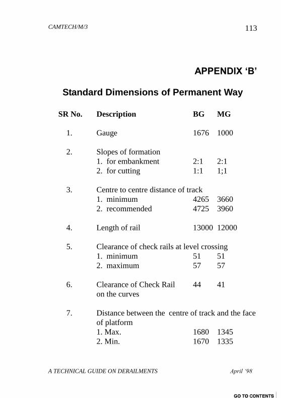
CAMTECH/M/3
A TECHNICAL GUIDE ON DERAILMENTS April ‘98
113
APPENDIX „B‟
Standard Dimensions of Permanent Way
SR No. Description BG MG
1. Gauge 1676 1000
2. Slopes of formation
1. for embankment 2:1 2:1
2. for cutting 1:1 1;1
3. Centre to centre distance of track
1. minimum 4265 3660
2. recommended 4725 3960
4. Length of rail 13000 12000
5. Clearance of check rails at level crossing
1. minimum 51 51
2. maximum 57 57
6. Clearance of Check Rail 44 41
on the curves
7. Distance between the centre of track and the face
of platform
1. Max. 1680 1345
2. Min. 1670 1335
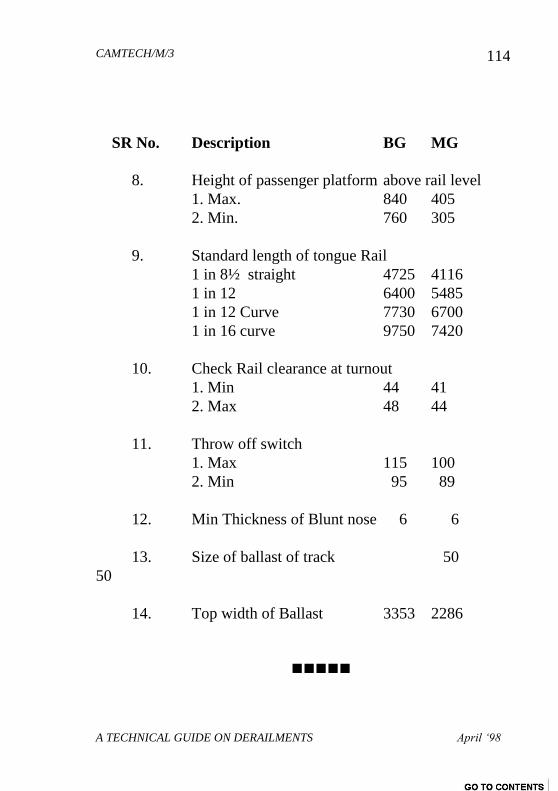
CAMTECH/M/3
A TECHNICAL GUIDE ON DERAILMENTS April ‘98
114
SR No. Description BG MG
8. Height of passenger platform above rail level
1. Max. 840 405
2. Min. 760 305
9. Standard length of tongue Rail
1 in 8½ straight 4725 4116
1 in 12 6400 5485
1 in 12 Curve 7730 6700
1 in 16 curve 9750 7420
10. Check Rail clearance at turnout
1. Min 44 41
2. Max 48 44
11. Throw off switch
1. Max 115 100
2. Min 95 89
12. Min Thickness of Blunt nose 6 6
13. Size of ballast of track 50
50
14. Top width of Ballast 3353 2286

CAMTECH/M/3
A TECHNICAL GUIDE ON DERAILMENTS April ‘98
115
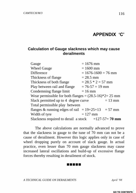
CAMTECH/M/3
A TECHNICAL GUIDE ON DERAILMENTS April ‘98
116
APPENDIX „C‟
Calculation of Gauge slackness which may cause
derailments
Gauge = 1676 mm
Wheel Gauge = 1600 mm
Difference = 1676-1600 = 76 mm
Thickness of flange = 28.5 mm
Thickness of both flange = 28.5 * 2 = 57 mm
Play between rail and flange = 76-57 = 19 mm
Condemning flange limit = 16 mm
Wear permissible for both flanges = (28.5-16)*2= 25 mm
Slack permitted up to 4 degree curve = 13 mm
Total permissible play between
flanges & running edges of rail = 19+25+13 = 57 mm
Width of tyre = 127 mm
Slackness required to derail a stock =127-57= 70 mm
The above calculations are normally advanced to prove
that the slackness in gauge to the tune of 70 mm can not be a
cause of derailment. However this logic applies only in case of
wheel dropping purely on account of slack gauge. In actual
practice, even lesser than 70 mm gauge slackness may cause
increased lateral oscillations and build-up of excessive flange
forces thereby resulting in derailment of stock.
CAMTECH/M/3
A TECHNICAL GUIDE ON DERAILMENTS April ‘98
117
APPENDIX „D‟
Extract from INDIAN RAILWAYS PERMANENT
WAY MANUAL (1986) CHAPTER VII
ACTION DURING ACCIDENTS INCLUDING
BREACHES AND PRE-MONSOON PRECAUTIONARY
MEASURES
704. Action at Site- (1) By Permanent Way and other
Engineering Inspectors - (a) Protect Train.- Any engineering
staff available at the site of accident shall assist the Guard and
Driver to protect the train in accordance with General Rules 6.03
and 9.10 (1976). The Inspector should ensure that protection has
been afforded to the train in front and in the rear, in accordance
with the rules. In the case of double line, if the other line is also
affected by the accident, steps shall be taken to protect both the
lines. If no infringement exists, trains must be controlled and
passed cautiously on the unaffected track.
(b) First Aid and Rescue.- The Inspector should arrange
for first aid to injured passengers and Railway staff and rescue of
trapped persons. If there is any Medical Practitioner on the train,
his assistance should be obtained.
(c) Advice to nearest Station Master.- After a rapid
survey of the position, particulars should be sent to the nearest
CAMTECH/M/3
A TECHNICAL GUIDE ON DERAILMENTS April ‘98
118
Station Master as in Para 702 above. In case of controlled
sections, a field telephone should be got commissioned at once.
(d) Line Clear examination.-If the engineering official
has reached the site and no traffic official is available, he should
carefully secure the line clear token or ticket and any caution
order, where necessary. If the accident has occurred in a station
yard, the train register book must be seized and if necessary,
statement of staff concerned recorded; if line badges are in use,
it should be recorded as to in whose possession each line badge
was. The position of block instruments, signals, points, point
levers, indicators, key etc. should be noted and recorded, jointly
with the Inspectors of the other concerned departments,
available at site.
(e) Preliminary clearing operation and preservation of
clues.- (i) In all instances in which the means taken for the
restoration of communication are likely to obliterate marks on
the road and other evidence needed at a joint enquiry, the senior
official who arrives first on the spot should carefully examine
the track, train or vehicle and as soon as possible make notes,
sketches, etc. and hand over the same to his superior or produce
them at the enquiry. He will, when the nature of the accident is
such as will involve the question of eye-sight of any of the
staff, verify (in case of those permitted to wear glasses) that they
had worn glasses at the time of the accident and had carried a
spare pair of glasses with them.
(ii) In all cases of accidents, the cause of which might
possibly due to sabotage, it is essential that the clearance and
restoration operation are not commenced till the Police officials
CAMTECH/M/3
A TECHNICAL GUIDE ON DERAILMENTS April ‘98
119
arrive at the site and intimate their agreement to the
commencement of clearance and restoration work, after making
thorough investigations.
A factual note of the conditions obtaining at the site prior
to restoration work should be prepared and signed jointly by the
senior most of the Police and Railway officials, such difference
of opinion may be recorded on the joint factual note.
This should not, however, be allowed to interfere with
rendering of first aid to the injured, which is the first essential in
all accidents.
(iii) In other cases, clearance and restoration operations
can commence well before the arrival of the Police and it is not
necessary that all the rails, sleepers and fastenings involved in an
accident should be preserved, but only those, whether
serviceable or otherwise, which wear wheel marks, etc.,
specially between the points of mount and drop. In all cases of
serious derailments, these are essential for a later reconstruction
of the scene and should bee preserved and/or recorded by the
first responsible officials to reach the site of the accident, as
these would be valuable evidence to ascertain the cause of the
accident.
(iv) After the injured persons have been attended to and
arrangements made for the onward journey of the standard
passengers, the Railway officers at the site of the accident
should arrange to record the preliminary statements of the staff
concerned, as any delay in doing so, might result in some facts
being suppressed or some evidence being fabricated during
CAMTECH/M/3
A TECHNICAL GUIDE ON DERAILMENTS April ‘98
120
subsequent enquiries.
(v) In case sabotage is suspected, the procedure as
outlined in clause (ii) above should be followed. In addition it
should be ascertained promptly from the C.R.S. if he would like
to inspect the site, etc. before the commencement of clearance
and restoration work and then action should be taken in
accordance with his wishes. Before clearance and restoration
operations are commenced, all relevant clues, materials and
damages and the deficiencies on Rolling Stock, etc. must be
noted and preserved. In other serious accidents, however, the
same procedure as outlined in Clause (iii) above should be
strictly followed.
***************************************************
707. Examination of site and preparation of sketches.
The first Engineering representative to arrive at site shall attend
to the following :-
(1) He should examine the entire site inclusive of track
over which the train has passed immediately before derailing,
noting down any unusual features observed, especially any parts
of vehicles or other material lying on or near the track.
(2) A dimensioned sketch should be prepared covering
the entire site of accident, showing all relevant features inclusive
of track leading upto point of derailment, showing position of
derailed vehicle, point of mount and drop and other relevant
details. All the details given in Annexure 7/1 should be
incorporated in the sketch.
CAMTECH/M/3
A TECHNICAL GUIDE ON DERAILMENTS April ‘98
121
(3) He should record the particulars as detailed in para
708 (1).
(4) An examination of the derailed vehicle/vehicles for
defects not caused by the derailment but which may have been
the cause of the derailment should be made. He should make out
notes for inclusion in the joint report.
(5) He should examine the gang-chart/diary books to
ascertain the date when track was last attended.
(6) Details of Engineering works in progress, if any, at
the site of accident, caution orders in force and nature of
protection should be noted.
***************************************************
708. Recording particulars at site of accident. - (1)
Permanent Way particulars.- Permanent way particulars shall
be recorded jointly with the Inspectors of the other concerned
departments as per Annexure 7/2. These records will inter alia
include particulars of the track structures, the condition of the
track components, track geometry and other relevant details.
(2) Particulars with respect to Rolling Stock and
Signalling.- Engineering representative should associate himself
with the concerned representative of the other departments in
recording measurements of-
CAMTECH/M/3
A TECHNICAL GUIDE ON DERAILMENTS April ‘98
122
(a) The locomotive and tender;
(b) Carriages and Wagons; and
(c) Signalling and telecommunication equipment.
(3) Operating particulars.- The following operating
particulars should also be recorded wherever relevant :-
(a) Speed.- The actual speed at the time of derailment, from
the speedometer graph or if the locomotive is not provided with
the speedometer graph, by referring to inter-station timings.
(b) The direction of the locomotive i.e., shorthood or
longhood leading.
(c) The brake power of the train.
(d) The marshalling of the train with reference to orders
applicable on the section.
(e) Whether there has been sudden application of brakes.
(f) whether there was sudden opening of regulators.
(g) Condition of loading in wagons, specially unequal
loading, light loading, empties between loaded vehicles, over-
loading, moving loads and any infringement to standard
dimensions.
(h) Particulars of Caution Orders issued to the Driver/
Guard.
CAMTECH/M/3
A TECHNICAL GUIDE ON DERAILMENTS April ‘98
123
***************************************************
APPENDIX „E‟
Excerpts from “FRENCH RAILWAY TECHNIQUES”
Special number no. 1/1978
The guiding of a Railway vehicle, be it a power vehicle
or a trailer, owes nothing to the flanges which are no more than
block stops for exceptional situation :
- abnormal running surface wear
- cant excess or deficiency or
- negotiations of switch and crossing work
Normally it is ensured by the action of the VISCO elastic
contact forces between the conical surfaces of the wheels, both
solidly attached to the same axle, and the cylindrical surfaces of
the rails.
2. If the cone angle is insufficient, the restoring forces
towards the centre disappear and the moving wheelset bears
permanently against one of the flanges, which is not designed for
that.
3. If the angle is excessive, the restoring force if excessive,
of short wave length, say 20 M or less.
4. With a concity, which according to calculation and
experience should be about 1/40 or 0.025, the hunting
CAMTECH/M/3
A TECHNICAL GUIDE ON DERAILMENTS April ‘98
124
wavelenghth is about 30 M, and the restoring force is
sufficiently moderate to be easily controlled by the suspension.
5. Under these conditions, the contact between rail and
wheel, far from sweeping the full clearance of from 18 to 20 mm
between the wheel set and track, is confined to some 8 mm.
6. Within that width, the movement is in no way random
but is determined by the track parameters, gauge, levelling,
inclination of the wheels and the shape of the running surfaces;
as between one day and another, a given TGV wheel set make
contact with the rail in accordance with practically identical
trajectories(rolling lines).
7. The oscillatory graph movements of the logic about its
vertical axis are in harmony with its hunting movements and
their angular amplitude does not excess 2.5 M. radius or about
10 minutes of arc.
8. All other things being equal, a definite limit is set to that
ideal situation by the critical speed.
CAMTECH/M/3
A TECHNICAL GUIDE ON DERAILMENTS April ‘98
125
GLOSSARY
Ballast
The material used as elastic cushion between sleepers
and the top of formation is called ballast.
Cant or Superelevation
On curves, outer rail of the track is raised higher than the
inner rail. This difference of level is called Super-
elevation or cant
Cant deficiency
The difference between the cant necessary for the
maximum permissible speed on a curve and actual cant
provided.
Cross level
The relative difference in vertical levels measured at the
top of the left and right rails at a given point on the track.
Creep
The longitudinal movement of rails in the track is called
Creep.
CAMTECH/M/3
A TECHNICAL GUIDE ON DERAILMENTS April ‘98
126
Deep flange
When depth of the flange becomes more than 35 mm.
Flange force
Force generated by wheel flange during movement of
wheel on the track.
Formation
Flat surface of earthwork on embankments or on cuttings
for laying railway track is called Formation.
Gauge
The distance between two running edges of the rails.
Gradient
Amount of slope in longitudinal direction in a railway
track is called gradient or grade.
Hollow tyre
Tyre hollowness exceeding 5 mm.

CAMTECH/M/3
A TECHNICAL GUIDE ON DERAILMENTS April ‘98
127
Point & Crossing
Assembly of components which enables the trains to
move from one track to other is called Point &
Crossing.
Running edge of the rail
The rail edge on which wheel flange contacts the rail.
Sharp flange
Flange worn out in such a way that radius at the tip of
flange reduces below 5mm.
Stock rail
Rail of the main line track against which tongue rails fit .
Switch
Stock rail and its respective tongue rail form a switch.
Tongue rail
The tapered rails whose thicker end is known as Heel are
fixed to the main track and the thinner end, known as
Toe of the switch.
CAMTECH/M/3
A TECHNICAL GUIDE ON DERAILMENTS April ‘98
128
Thin flange
Flange thickness below 16mm.
Throw of switch
The distance through which the tongue rail moves at the
toe of switch is called throw of switch. Its value on
Indian railway is 114mm.
Twist
The rate of change of variation in cross level per meter.
Transition of curve
It is an easement of curve in which change of degree is
uniform.
Wheel base
The distance between the two adjacent axles of a bogie is
called wheel base.
Wheel gauge
The distance between the inner surface of flanges of left
and right wheel mounted on an axle.
CAMTECH/M/3
A TECHNICAL GUIDE ON DERAILMENTS April ‘98
129
BIBLIOGRAPHY
1. Indian Railways Conference Association, Ministry of
Railways, Government of India. CONFERENCE RULES
Part III, 1973. 304 pp.
2. Indian Railways Conference Association, Ministry of
Railways, Government of India. CONFERENCE RULES
Part IV , 1982. 358 pp.
3. Krishna Rao S.H.R. RDSO TECHNICAL MONOGRAPH
NO.35 : DERAILMENTS. Lucknow : Research Design and
Standards Organisation, 1971. 76 pp.
4. Raman R. A BASIC STUDY ON MID SECTION
DERAILMENTS OF METRE GAUGE FOUR-WHEELED
GOODS STOCK. Madras : SOLAR WORKS. 32 pp.
5. Katiyal R.C. PREVENTION OF ACCIDENTS. 220 pp.
6. Agarwal M.M. INDIAN RAILWAY TRACK. Delhi :
PRABHA & Co., 1988. 570 pp.
7. Ministry of Railways, Government of India. THE
INVESTIGATION OF DERAILMENTS. Pune:Indian Railways
Institute of Civil Engineering, 1995. 286 pp.
8. Doraiswami P.N. DERAILMENTS INVESTIGATIONS.
Chennai : IND-COM PRESS, 1991. 333 pp.
CAMTECH/M/3
A TECHNICAL GUIDE ON DERAILMENTS April ‘98
130
9. Mundrey J.S. RAILWAY TRACK ENGINEERING. Delhi :
Tata McGraw Hills, 1988. 483 pp.
10. Duncan G.T. et. al. A GUIDE TO THE INVESTIGATION
OF DERAILMANTS. British Rail, 1985. H39 pp.
11. Ministry of Railways, Government of India. INDIAN
RAILWAYS PERMANENT WAY MANUAL. Delhi:
Director Civil Engineering, 1986. 1505 pp.
CAMTECH/M/3
A TECHNICAL GUIDE ON DERAILMENTS April ‘98
131
INDEX
A
angle of attack, 10, 13, 14, 19,
26
angular wear, 57, 59, 77, 78
angularity, 10, 11, 12, 13, 14,
15, 22, 23, 42, 58, 59
axle load, 25
B
Ballast, 50, 51, 52, 53, 54
C
Cant, 22, 79, 80, 81
cant excess or deficiency or,
18, 22
Causes of Creep, 68
Coefficient of friction, 8
Creep, 68, 69, 72, 73, 74
Cross level, 22, 64, 83
Curves, 57
D
Degree of Curve, 80, 86
Derailment Investigation, 3
Displaced Buffer, 48
F
False Flange, 42, 43
Flange force, 3
G
Gauge Distortion, 60
Gradient, 70
L
Length of Transition, 84
M
Mounting, 6, 29
N
negotiations of switch and
crossing work, 18, 22
S
Sleepers, 50, 55, 76
Speed, 21, 30, 78
Super elevation, 22
CAMTECH/M/3
A TECHNICAL GUIDE ON DERAILMENTS April ‘98
132
T
Thin Flange, 39
Twist, 22, 63, 65, 66, 67
U
Unbalanced Traffic, 70
Uneven Loading, 18
V
Versine, 22, 85, 86
Virtual Gauge, 20
W
Wheel base, 69
Wheel gauge, 15, 34, 39
wheel load, 7, 15, 16, 19, 23,
31

A TECHNICAL GUIDE ON DERAILMENTS April ‘98
Recommended