Proceedings of the 2nd World Congress on Mechanical, Chemical, and Material Engineering (MCM'16) Budapest, Hungary – August 22 – 23, 2016 Paper No. HTFF 129
DOI: 10.11159/htff16.129
HTFF 129-1
Heat Transfer Enhancement Methods: Concave and Convex Shape Fins
Irfan Kurtbas1, Alptug Yataganbaba1, Mehmet Sener2, Aslı Karakas1 1Hitit University, Faculty of Engineering, Department of Mechanical Engineering, North Campus, Corum, 19030,
TURKEY 2Hitit University, Scientific Technical Application and Research Centre; North Campus, Corum, 19030, TURKEY
[email protected]; [email protected]; [email protected]
Abstract - The heat transfer coefficient is a common engineering concept and a significant number of researchers are focusing on
improving the heat transfer performance of the system by increasing the heat transfer coefficient. Heat transfer enhancement techniques
are broadly classified in three broad categories: passive, active and compound techniques. This study is concerned with the effect of fins
placed inside a rectangular channel on heat transfer and pressure drop to be concave and convex against flow. The effect of some
independent parameters such as Reynolds number, height, diameter, number and angle of the fins on Nusselt number, friction coefficient
were experimentally studied. Turbulent flow experiments were performed for the range 2514-13111 of Reynolds number. The results
showed that Reynolds number is the most effective parameter. Based on the Reynolds number, the heat transfer increased between 1.4-
2.8 times, friction coefficient increased between 1.1-3.4 times according to smooth channel. Keywords: Heat transfer enhancement techniques, passive method, concave and convex fins
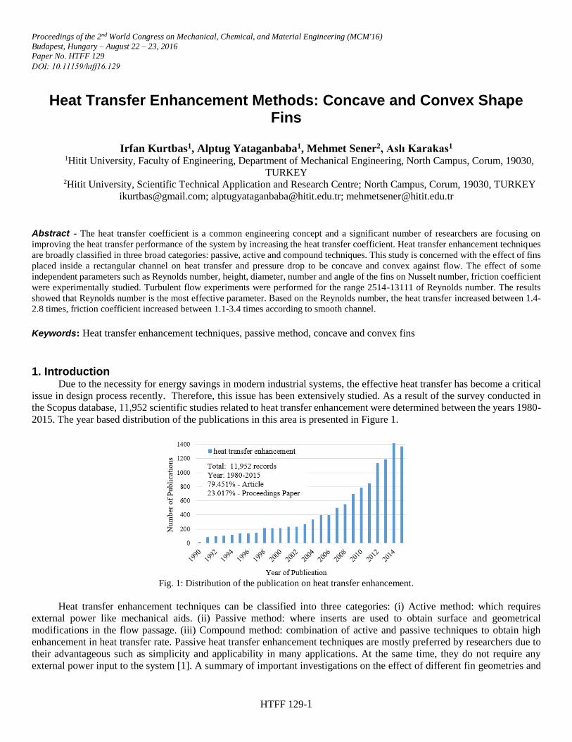
1. Introduction Due to the necessity for energy savings in modern industrial systems, the effective heat transfer has become a critical
issue in design process recently. Therefore, this issue has been extensively studied. As a result of the survey conducted in
the Scopus database, 11,952 scientific studies related to heat transfer enhancement were determined between the years 1980-
2015. The year based distribution of the publications in this area is presented in Figure 1.
Fig. 1: Distribution of the publication on heat transfer enhancement.
Heat transfer enhancement techniques can be classified into three categories: (i) Active method: which requires
external power like mechanical aids. (ii) Passive method: where inserts are used to obtain surface and geometrical
modifications in the flow passage. (iii) Compound method: combination of active and passive techniques to obtain high
enhancement in heat transfer rate. Passive heat transfer enhancement techniques are mostly preferred by researchers due to
their advantageous such as simplicity and applicability in many applications. At the same time, they do not require any
external power input to the system [1]. A summary of important investigations on the effect of different fin geometries and
HTFF 129-2
configurations is presented in Table 1. Although some research has been carried out on passive heat transfer enhancement
methods, especially usage of fins, there is still very little experimental understanding of the effect of different fin geometries
and dimensions.
Table 1: Summary of important investigations on fins as heat transfer enhancement method.
Authors Configuration of fin
Type of investigation
Observations
Aziz and
Fang [2]
Rectangular,
trapezoidal and
concave
numerical the relationship between the dimensionless heat flux,
the fin parameter, and dimensionless tip temperature for
these geometries
Jafarpur and
Jayhooni [3]
convex and concave numerical the effect of convexity and concavity on laminar natural
convection
Mokheimer
[4]
rectangular,
triangular, concave
parabolic and
convex parabolic
profiles
numerical to obtain the local heat transfer coefficient as a function
of the local temperature for desired geometries
Abou-Ziyan
et al. [5]
helical fins experiment
al
to evaluate the effects of interrupted helical fins on the
heat transfer and pressure drop characteristics in
annular passage
Awasarmol
and Pise [6]
rectangular fins experiment
al
to compare the natural convection heat transfer
enhancement of perforated fin array with different
perforation diameter and at different angles
Lee et al. [7]
oblique fins experimental and numerical
employing sectional oblique fins to modulate flow in a microchannel heat sink
The current study aims to contribute to the literature and investigate the effect of convex and concave fins on heat
transfer and friction coefficient.
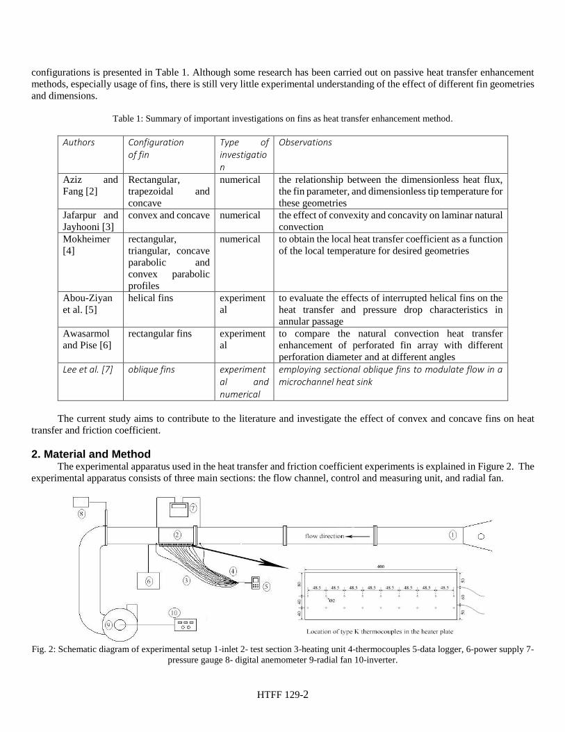
2. Material and Method The experimental apparatus used in the heat transfer and friction coefficient experiments is explained in Figure 2. The
experimental apparatus consists of three main sections: the flow channel, control and measuring unit, and radial fan.
Fig. 2: Schematic diagram of experimental setup 1-inlet 2- test section 3-heating unit 4-thermocouples 5-data logger, 6-power supply 7-
pressure gauge 8- digital anemometer 9-radial fan 10-inverter.
HTFF 129-3
The total length of flow channel was 4m and it was manufactured with 8mm thick transparent plexiglass. The 0.4m
part of the flow channel was separated as test section and 3.6m part separated as inlet section to ensure the fully development
of the channel. The interior dimensions of the test section were 140mm (width) and 100mm (height). Based on the these
dimensions, the width to height ratio and equivalent diameter of the flow channel was determined as 1.4 and 116.66mm,
respectively. The resistances were placed inside the heater plate as possible as dense and uniformly in order to obtain a
homogeneous distribution of heat flux on the heater surface. The heater plate was produced specifically (0.4m length, 0.16m
width) by a company that manufactures heating elements to obtain constant heat flux. The total power of the heater plate was
1000W and it was controlled by DC power supply (NETES PS-360 3D). The experimental apparatus was operated in the
suction mode and this was obtained with a 1.1 kW radial fan. Fan speed was changed with the help of frequency converter.
So, it was given the opportunity to examine the effect of Reynolds number on the heat transfer and friction coefficient.
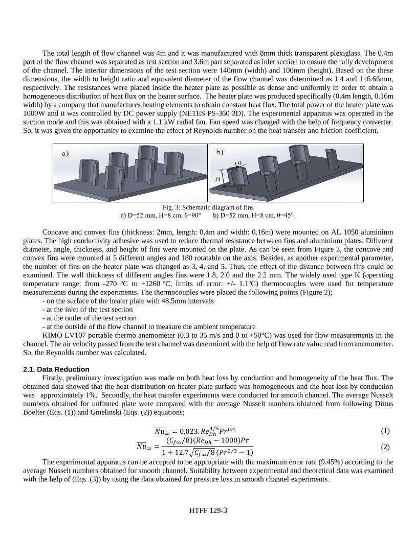
Fig. 3: Schematic diagram of fins
a) D=52 mm, H=8 cm, θ=90° b) D=52 mm, H=8 cm, θ=45°.
Concave and convex fins (thickness: 2mm, length: 0,4m and width: 0.16m) were mounted on AL 1050 aluminium
plates. The high conductivity adhesive was used to reduce thermal resistance between fins and aluminium plates. Different
diameter, angle, thickness, and height of fins were mounted on the plate. As can be seen from Figure 3, the concave and
convex fins were mounted at 5 different angles and 180 rotatable on the axis. Besides, as another experimental parameter,
the number of fins on the heater plate was changed as 3, 4, and 5. Thus, the effect of the distance between fins could be
examined. The wall thickness of different angles fins were 1.8, 2.0 and the 2.2 mm. The widely used type K (operating
temperature range: from -270 oC to +1260 oC, limits of error: +/- 1.1oC) thermocouples were used for temperature
measurements during the experiments. The thermocouples were placed the following points (Figure 2);
- on the surface of the heater plate with 48,5mm intervals
- at the inlet of the test section
- at the outlet of the test section
- at the outside of the flow channel to measure the ambient temperature
KIMO LV107 portable thermo anemometer (0.3 to 35 m/s and 0 to +50°C) was used for flow measurements in the
channel. The air velocity passed from the test channel was determined with the help of flow rate value read from anemometer.
So, the Reynolds number was calculated.
2.1. Data Reduction Firstly, preliminary investigation was made on both heat loss by conduction and homogeneity of the heat flux. The
obtained data showed that the heat distribution on heater plate surface was homogeneous and the heat loss by conduction
was approximately 1%. Secondly, the heat transfer experiments were conducted for smooth channel. The average Nusselt
numbers obtained for unfinned plate were compared with the average Nusselt numbers obtained from following Dittus
Boelter (Eqs. (1)) and Gnielinski (Eqs. (2)) equations;
𝑁𝑢̅̅ ̅̅ ∞ = 0.023. 𝑅𝑒𝐷ℎ4 5⁄ 𝑃𝑟0.4 (1)
𝑁𝑢̅̅ ̅̅ ∞ =(𝐶𝑓∞ 8)(𝑅𝑒𝐷ℎ − 1000)𝑃𝑟⁄
1 + 12.7√𝐶𝑓∞ 8⁄ (𝑃𝑟2 3⁄ − 1) (2)
The experimental apparatus can be accepted to be appropriate with the maximum error rate (9.45%) according to the
average Nusselt numbers obtained for smooth channel. Suitability between experimental and theoretical data was examined
with the help of (Eqs. (3)) by using the data obtained for pressure loss in smooth channel experiments.
HTFF 129-4
∆𝑃 = 𝑓𝐿
𝐷𝐻
𝜌𝑉2
2 (3)
The obtained values were found to be 20% different from the theoretical values.
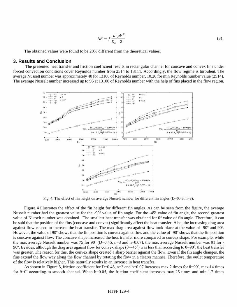
3. Results and Conclusion The presented heat transfer and friction coefficient results in rectangular channel for concave and convex fins under
forced convection conditions cover Reynolds number from 2514 to 13111. Accordingly, the flow regime is turbulent. The
average Nusselt number was approximately 40 for 13100 of Reynolds number, 10.26 for min Reynolds number value (2514).
The average Nusselt number increased up to 96 at 13100 of Reynolds number with the help of fins placed in the flow region.
Fig. 4: The effect of fin height on average Nusselt number for different fin angles (D=0.45, n=3).
Figure 4 illustrates the effect of the fin height for different fin angles. As can be seen from the figure, the average
Nusselt number had the greatest value for the -90o value of fin angle. For the -45o value of fin angle, the second greatest
value of Nusselt number was obtained. The smallest heat transfer was obtained for 0o value of fin angle. Therefore, it can
be said that the position of the fins (concave and convex) significantly affect the heat transfer. Also, the increasing drag area
against flow caused to increase the heat transfer. The max drag area against flow took place at the value of -90o and 90o.
However, the value of 90o shows that the fin position is convex against flow and the value of -90o shows that the fin position
is concave against flow. The concave shape increased the heat transfer more compared to convex shape. For example, while
the max average Nusselt number was 75 for 90o (D=0.45, n=3 and h=0.07), the max average Nusselt number was 91 for -
90o. Besides, although the drag area against flow for convex shape (θ=-45˚) was less than according to θ=90˚, the heat transfer was greater. The reason for this, the convex shape created a sharp barrier against the flow. Even if the fin angle changes, the
fins extend the flow way along the flow channel by rotating the flow in a clearer manner. Therefore, the outlet temperature
of the flow is relatively higher. This naturally results in an increase in heat transfer.
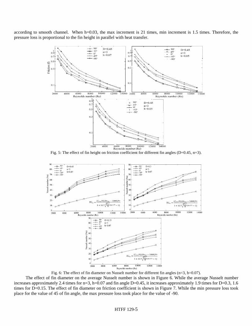
As shown in Figure 5, friction coefficient for D=0.45, n=3 and h=0.07 increases max 2 times for θ=90˚, max 14 times for θ=0˚ according to smooth channel. When h=0.05, the friction coefficient increases max 25 times and min 1.7 times
HTFF 129-5
according to smooth channel. When h=0.03, the max increment is 21 times, min increment is 1.5 times. Therefore, the
pressure loss is proportional to the fin height in parallel with heat transfer.
Fig. 5: The effect of fin height on friction coefficient for different fin angles (D=0.45, n=3).
Fig. 6: The effect of fin diameter on Nusselt number for different fin angles (n=3, h=0.07).
The effect of fin diameter on the average Nusselt number is shown in Figure 6. While the average Nusselt number
increases approximately 2.4 times for n=3, h=0.07 and fin angle D=0.45, it increases approximately 1.9 times for D=0.3, 1.6
times for D=0.15. The effect of fin diameter on friction coefficient is shown in Figure 7. While the min pressure loss took
place for the value of 45 of fin angle, the max pressure loss took place for the value of -90.
HTFF 129-6
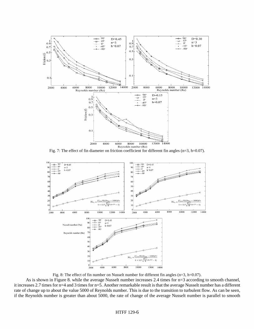
Fig. 7: The effect of fin diameter on friction coefficient for different fin angles (n=3, h=0.07).
Fig. 8: The effect of fin number on Nusselt number for different fin angles (n=3, h=0.07).
As is shown in Figure 8. while the average Nusselt number increases 2.4 times for n=3 according to smooth channel,
it increases 2.7 times for n=4 and 3 times for n=5. Another remarkable result is that the average Nusselt number has a different
rate of change up to about the value 5000 of Reynolds number. This is due to the transition to turbulent flow. As can be seen,
if the Reynolds number is greater than about 5000, the rate of change of the average Nusselt number is parallel to smooth
HTFF 129-7
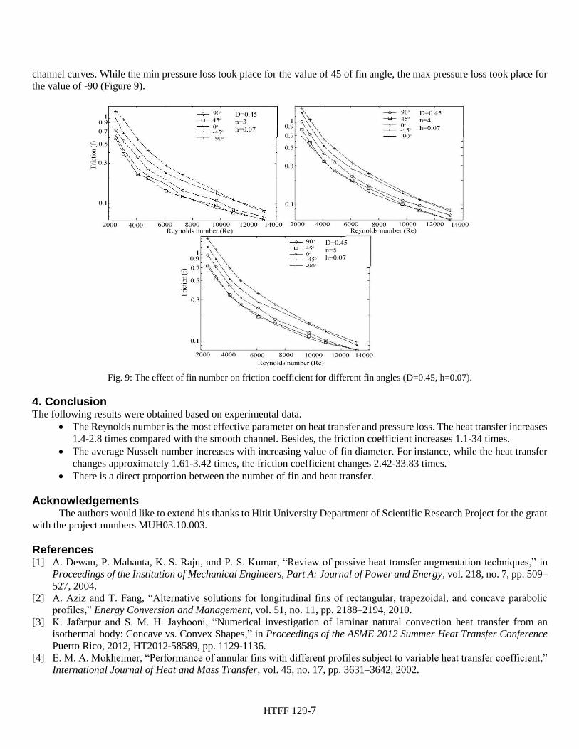
channel curves. While the min pressure loss took place for the value of 45 of fin angle, the max pressure loss took place for
the value of -90 (Figure 9).
Fig. 9: The effect of fin number on friction coefficient for different fin angles (D=0.45, h=0.07).
4. Conclusion The following results were obtained based on experimental data.
The Reynolds number is the most effective parameter on heat transfer and pressure loss. The heat transfer increases
1.4-2.8 times compared with the smooth channel. Besides, the friction coefficient increases 1.1-34 times.
The average Nusselt number increases with increasing value of fin diameter. For instance, while the heat transfer
changes approximately 1.61-3.42 times, the friction coefficient changes 2.42-33.83 times.
There is a direct proportion between the number of fin and heat transfer.
Acknowledgements The authors would like to extend his thanks to Hitit University Department of Scientific Research Project for the grant
with the project numbers MUH03.10.003.
References [1] A. Dewan, P. Mahanta, K. S. Raju, and P. S. Kumar, “Review of passive heat transfer augmentation techniques,” in
Proceedings of the Institution of Mechanical Engineers, Part A: Journal of Power and Energy, vol. 218, no. 7, pp. 509–527, 2004.
[2] A. Aziz and T. Fang, “Alternative solutions for longitudinal fins of rectangular, trapezoidal, and concave parabolic profiles,” Energy Conversion and Management, vol. 51, no. 11, pp. 2188–2194, 2010.
[3] K. Jafarpur and S. M. H. Jayhooni, “Numerical investigation of laminar natural convection heat transfer from an
isothermal body: Concave vs. Convex Shapes,” in Proceedings of the ASME 2012 Summer Heat Transfer Conference
Puerto Rico, 2012, HT2012-58589, pp. 1129-1136.
[4] E. M. A. Mokheimer, “Performance of annular fins with different profiles subject to variable heat transfer coefficient,” International Journal of Heat and Mass Transfer, vol. 45, no. 17, pp. 3631–3642, 2002.

HTFF 129-8
[5] H. Z. Abou-Ziyan, A. H. B. Helali, and M. Y. E. Selim, “Enhancement of forced convection in wide cylindrical annular channel using rotating inner pipe with interrupted helical fins,” International Journal of Heat and Mass Transfer, vol.
95, pp. 996–1007, 2016.
[6] U. V. Awasarmol and A. T. Pise, “An experimental investigation of natural convection heat transfer enhancement from perforated rectangular fins array at different inclinations,” Experimental Thermal and Fluid Science, vol. 68, pp. 145–154, 2015.
[7] Y. J. Lee, P. S. Lee, and S. K. Chou, “Enhanced thermal transport in microchannel using oblique fins,” Journal of Heat
Transfer, vol. 134, pp. 101901, 2012.
Recommended


![Convex lens Concave lensbh.knu.ac.kr/~ilrhee/lecture/modern/chap6.pdf · 2017-11-13 · Convex lens Concave lens Optical lens 공기중에사용 Diopter [예제] 곡률반경이R](https://img.pdfslide.net/doc/110x75/5f0845f47e708231d4213166/convex-lens-concave-ilrheelecturemodernchap6pdf-2017-11-13-convex-lens-concave.jpg)