HP/Cisco Switching and Routing
Interoperability Cookbook
May 2011
HP/Cisco Interoperability Configuration Cookbook
Pag
e2
T A B L E O F C O N T E N T S Introduction .................................................................................................................................... 3
Interoperability testing ................................................................................................................... 5
Virtual LAN (VLAN) trunking ........................................................................................................ 7
Jumbo frame switching ............................................................................................................. 10
Jumbo frame routing ................................................................................................................. 14
Link aggregation ........................................................................................................................ 18
Spanning tree case 1: RSTP/Rapid-PVST+ ................................................................................. 21
Spanning tree case 2: MSTP/PVST+ .......................................................................................... 25
Spanning tree case 3: MSTP/Rapid-PVST+ ................................................................................ 30
Spanning tree case 4: MSTP/MSTP ........................................................................................... 34
OSPFv2 (OSPF for IPv4).............................................................................................................. 39
OSPFv3 (OSPF for IPv6).............................................................................................................. 44
IP multicast switching ................................................................................................................ 48
IP multicast routing ................................................................................................................... 50
Virtual router redundancy protocol (VRRP) interoperability .................................................... 56
Appendix A: About Network Test ................................................................................................. 60
Appendix B: Sample Configuration Files ....................................................................................... 60
Appendix C: Software Releases Tested ......................................................................................... 60
Appendix D: Disclaimer ................................................................................................................. 60
I L L U S T R A T I O N S Figure 1: HP-Cisco interoperability test bed ................................................................................... 6
Figure 2: Jumbo frame switching test bed .................................................................................... 12
Figure 3: Jumbo frame routing test bed ...................................................................................... 15
Figure 4: Link aggregation test bed............................................................................................... 19
Figure 5: Virtual router redundancy protocol test bed ................................................................ 57
Version 2011050900. Copyright © 2011 Network Test Inc. All rights reserved.
HP/Cisco Interoperability Configuration Cookbook
Pag
e3
Introduction
Objective
This configuration guide aims to help networking professionals interconnect HP Networking and
Cisco Catalyst switches using a variety of protocols commonly found in enterprise campus
networks. By following the step-by-step procedures described in this document, it should be
possible to verify interoperability and to pass traffic between the two vendors’ switches.
Intended audience
This guide is intended for any network architect, administrator, or engineer who needs to
interconnect HP and Cisco Ethernet switches.
This guide assumes familiarity with basic Ethernet and TCP/IP networking concepts, as well as
at least limited experience with the HP Networking and Cisco IOS command-line interfaces
(CLIs). No previous experience is assumed for the protocols discussed in this document.
For basic TCP/IP networking concepts, the standard references are Internetworking with
TCP/IP, Volume 1 by Douglas E. Comer and TCP/IP Illustrated, Volume 1 by W. Richard Stevens.
For IP multicast topics, Deploying IP Multicast in the Enterprise by Thomas A. Maufer is a
popular choice.
Devices under test
Using the commands given in this document, Network Test has verified interoperability
between the HP A9505, HP E5406zl, and HP A5800 Ethernet switches and Cisco Catalyst 6509,
Cisco Catalyst 4506, and Catalyst 3750-E Ethernet switches. Appendix B lists software versions
used.
Except where specifically noted, command syntax for HP Networking and Cisco Catalyst
switches does not change across product lines. In cases where HP A-series and E-series switches
use different command syntax, this is explicitly noted.
HP/Cisco Interoperability Configuration Cookbook
Pag
e4
Conventions used in this document
The following table lists text and syntax conventions.
Conventions Description Examples
Bold Type Represents user-inputted text. To enter configuration mode, type the
system-view command:
<HP5800> system-view
Fixed-width text like
this
Represents output that appears on
the terminal screen.
<A9505> display stp bridge
MSTID Port
Role STP State
Protection
0 Bridge-
Aggregation20 ROOT
FORWARDING NONE
0
GigabitEthernet3/0/11
DESI FORWARDING NONE
0
GigabitEthernet3/0/16
DESI FORWARDING NONE
Italic text like this Introduces important new
terms
Identifies book titles
Identifies RFC and Internet-
draft titles
A policy term is a named structure
that defines match conditions and
actions.
TCP/IP Illustrated Volume 1 by W.
Richard Stevens.
RFC 4814, Hash and Stuffing:
Overlooked Factors in Network
Device Benchmarking
HP/Cisco Interoperability Configuration Cookbook
Pag
e5
Interoperability testing For each protocol tested, this document uses a five-section format consisting of objective,
technical background, HP configuration, Cisco configuration, and test validation.
Topology
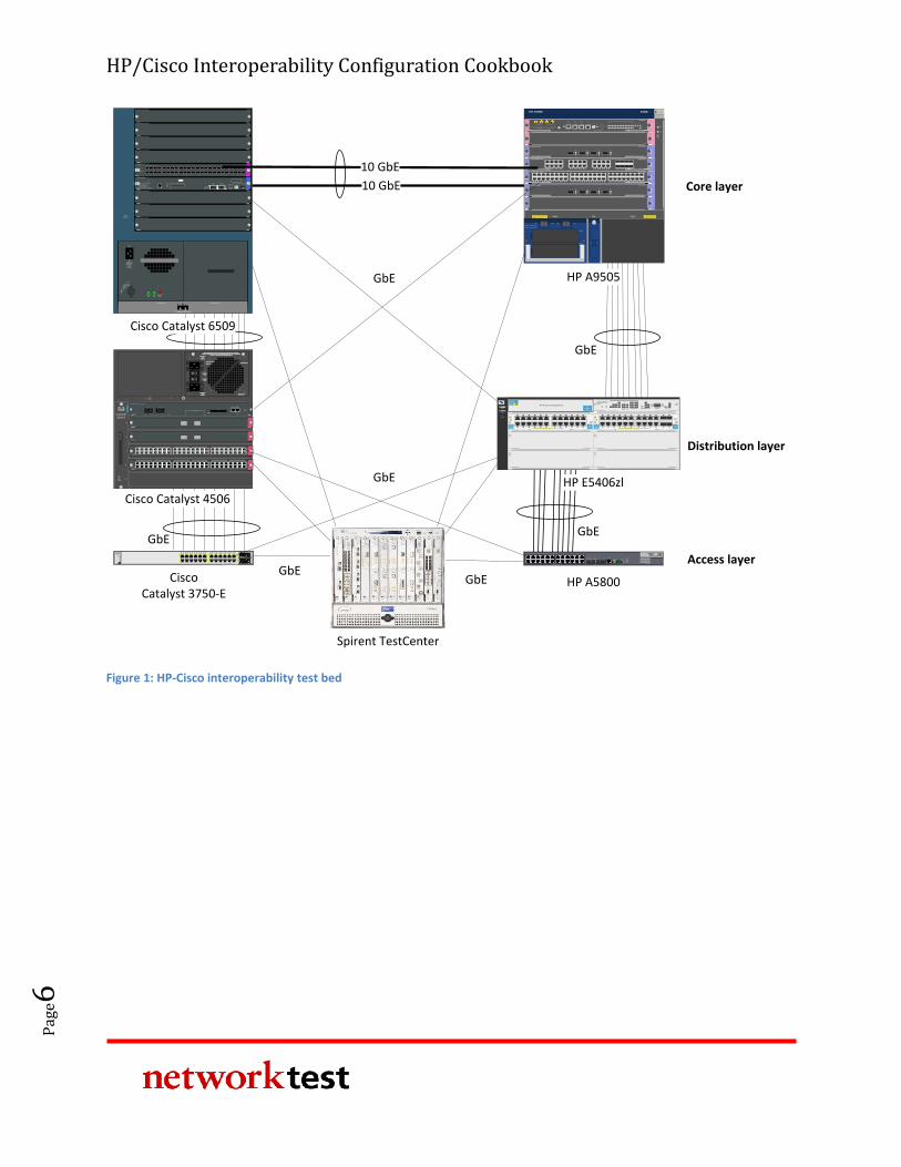
Except where otherwise noted, engineers used the standard test bed shown in Figure 1 below
to validate protocol interoperability. The test bed uses the three-tier network design commonly
found in campus enterprise networks, with access, distribution, and core layers represented. In
this example network, access switches (HP A5800 and Cisco Catalyst C3750-E) connect to
distribution switches (HP E5406zl and Cisco Catalyst 4506), which in turn connect to core
switches (HP A9505 and Cisco Catalyst 6509). For redundancy, multiple connections exist
between switch layers.
Test engineers configured link aggregation between HP A5800 and HP E5406zl switches;
between HP E5406zl and HP A9505 switches; between HP A9505 and Cisco Catalyst 6509
switches; between Cisco Catalyst 6509 and Cisco Catalyst 4506 switches; and between Cisco
Catalyst 4506 and Cisco Catalyst 3750-E switches. The use of link aggregation is not mandatory,
however.
HP/Cisco Interoperability Configuration Cookbook
Pag
e6
10 GbE
FANSTATUS
1
2
3
4
5
6
7
8
9
Power Supply 1 Power Supply 2
Catalyst 6500 SERIES
Cisco Catalyst 6509
100-240 V~16 A
60/50 Hz
INPUTOK
FANOK
OUTPUTFAIL
RUNIN
STALL
INPUT
WS-X6748-SFP
48 PORT GIGABIT ETHERNET SFP
STATUS
1 2 3 4 5 6 7 8 9 10 11 12 13 14 15 16 17 18 19 20 21 22 23 24 25 26 27 28 29 30 31 32 33 34 35 36 37 38 39 40 41 42 43 44 45 46 47 48
WS-SUP32-10GE-P3B
CATALYST 6500 SUPERVISOR ENGINE 32
SYSTEM
STATU
S
ACTIV
E
PWR
MG
MT
EJECT
DISK 0CONSOLEPORT 2PORT 1
LINK 1
LINK 2
RESET
TX RX TX RX
LINK
USB 2.0
PORT 3
E S D
This device has more than one power
input. DO disconnect all power inputs
to power off this device.
High leakage current,earth
connection essential before
connecting power supply.PWR2PWR1 POE
RUN
ALM
FAN
0
6
5
4
3
2
1
UP
H3C S9505E
POWER 1: ~100-240V;50/60Hz;16A
POWER 2: ~100-240V;50/60Hz;16A
POWER 1
POWER 2
ON1 OFF1 ON2 OFF2
10GBASE-R/W-XFP
21LINK
ACT
LINK
ACT
LSR1XP2LEB1
CF CARD
CLKIN
CLKO
UT C
FS
MG
MNT
ACT
LINK
RS232/485
CO
NSO
LE
AUX
RESET
USB
DEV U
SBS
HO
ST
LSR1SRP2C1
ALM
SFSAC
TRUN
LPU
5 6 7 8 90 1 2 3 4 10 11 12 13
LSR2GV48REB110/100/1000BASE-T-RJ45
1 2 3 4 5 6 7 8 9 10 11 12 13 14 15 16 17 18 19 20 21 22 23 24 25 26 27 28 29 30 31 32 33 34 35 36 37 38 39 40 41 42 43 44 45 46 47 48
48
47
2
1
15
16
17
18
31
32
33
34 LINK/ACTLINK/ACT
LINK/ACT
1 2 3 4 5 6 7 8 9 10 11 12 13 14 15 16 17 18 19 20 21 22 23 24
LINK/ACT
25 26 27 28 29 30 31 32
LSR1GT24LEC110/100/1000BASE-T-RJ45 COMBO
8
7
2
1
16
15
10
9
24
23
18
17
26
25
32
31
10GBASE-R/W-XFP LSR1XP4LEC1
3 421LINK
ACT
LINK
ACT
LINK
ACT
LINK
ACT
10GBASE-R/W-XFP
3 421LINK
ACT
LINK
ACT
LINK
ACT
LINK
ACT
LSR1XP4LEB1
H3C S5800 Series
SFP+10/100/1000Base-T
Speed:Green = 1000Mbps, Yellow = 10/100Mbps
Console
11 129 107 85 63 41 2 13 14 15 16 17 18 19 20 21 22 23 24
25 26 27 28
Green=10Gbps, Yellow=1Gbps
Duplex: Green=Full Duplex, Yellow =Half Duplex
SYS
RPS
SLOT1
Mode
Y ellow = Duplex
UnitGreen = Speed
zlmodule
ModuleStatus
ModuleLocator
HDDActivityModule
Shutdown
NetworkActivity
ONE Services Module
USB
Link/Act
Managment10/100/1000T
PCIe 1
PCIe 2
Avaya Aura SBCpowered by Acme Packet
TM
HP ONEExt Svcszl ModuleJ9543A
zlmodule
ModuleStatus
ModuleLocator
HDDActivityModule
Shutdown
NetworkActivity
ONE Services Module
USB
Link/Act
Managment10/100/1000T
PCIe 1
PCIe 2
Avaya Aura SBCpowered by Acme Packet
TM
HP ONEExt Svcszl ModuleJ9543A
C I S C OSYST
RPS
STAT
DUPLX
SPEED
MODE
1X
2X
11X
12X
1 2 3 4 5 6 7 8 9 10 11 12
25
X2-1
X2-2
MASTER
STACK
Catalyst 3750-E Series-24
27
26
28
13X
14X
23X
24X
13 14 15 16 17 18 19 20 21 22 23 24
Cisco Catalyst 3750-E
Spirent TestCenter
1
2
3
4
5
6
SU
PE
RV
ISO
R
Catalyst
4506-E
1
2
3
4
5
6FAN
STATUS
SU
PE
RV
ISO
R
Catalyst
4506-E
SWITCHED SHOULD BE IN THE OFF ‘O’ POSITION TO INSTALL /
REMOVE POWER SUPPLIES. FASTENERS MUST BE FULLY ENGAGED
PRIOR TO OPERATING POWER SUPPLY
100-240V~
12A
50/60Hz
OUTPUT FAIL
INPUT 1
OK
INPUT 2
OK
100-240V~
12A
50/60Hz
POE ENABLED
4200ACV
FAN OK
RESET
UPLINK 1 UPLINK 2
ACTIVELINK LINK ACTIVE ACTIVE
WS-X4516 SUPERVISOR ENGINE V
STATUS
EJECT
FLASH
CONSOLE
LINK
MGT10/100
UTILIZATION
100%1%
1000 BASE-X
STATUS
WS-X4302-GB
21
SWITCHING MODULE
1000 BASE-X
STATUS
WS-X4302-GB
21
SWITCHING MODULE
MAX 15.4W/PORT
STATUS
WS-X4548-GB-RJ45V
1 2 3 4 5 6 7 8 9 10 11 12 13 14 15 16
MULTI-SPEEDGIGABIT ETHERNET
SWITCHING MODULE
48-PORT10/100/1000 BASE T
IN-LINE POWER
3231
3029
2827
2625
2423
2221
2019
1817
4847
4645
4443
4241
4039
3837
3635
3433
1615
1413
1211
109
87
65
43
21
32313029282726252423222120191817 33 34 35 36 37 38 39 40 41 42 43 44 45 46 47 48
HP A5800
HP A9505
Cisco Catalyst 4506
Power
Fault
Locator
E F
C D
A
ProCurve NetworkingHP Innovation
zlProCurve
24p Gig-T
zl Module
J8702A PoE-Integrated 10/100/1000Base-T Ports (1-24) - Ports are IEEE Auto MDI/MDI-X
1 5
62
3
4
7 11
128
9
10
13 17
1814
15
16
19 23
2420
21
22 zlProCurve
24p Gig-T
zl Module
J8702A PoE-Integrated 10/100/1000Base-T Ports (1-24) - Ports are IEEE Auto MDI/MDI-X
1 5
62
3
4
7 11
128
9
10
13 17
1814
15
16
19 23
2420
21
22
ConsoleReset Clear
Auxiliary Port
ProCurve Switch 5400zl
Management Module
J8726A
Internal
PowerPoE
Pwr
2
1
2
4
1
3
PoE
Temp
Fan
Flash
DIMM
Mgmt
ChasTest
LED ModeModules
Status
Act
FDx
Spd Usr
PoE
H
J
LK
I
G
F
D
B
E
C
A
ProCurve
Switch 5406zl
J8699A PoE
Use
zl Modules
only
B
ProCurve
Switch 5406zl
J9447A
zlProCurve
Gig-T/SFP
zl Module
J9308A PoE-Integrated 10/100/1000Base-T Ports (1-24) - Ports are Auto MDIX
1 5
62
3
4
7 11
128
9
10
13 17
1814
15
16
19
20
23
24
21
22
Use only
HP ProCurve
SFPs
zlProCurve
Gig-T PoE+
zl Module
J9307A PoE-Integrated 10/100/1000Base-T Ports (1-24) - Ports are Auto MDIX
1 5
62
3
4
7 11
128
9
10
13 17
1814
15
16
19 23
2420
21
22
HP ProCurve Networking
HP E5406zl
GbE
GbE
GbE
GbEGbE
GbEGbE
Core layer
Distribution layer
Access layer
10 GbE
Figure 1: HP-Cisco interoperability test bed
HP/Cisco Interoperability Configuration Cookbook
Pag
e7
Virtual LAN (VLAN) trunking
Objective
To verify interoperability of IEEE 802.1Q VLAN trunking between HP Networking and Cisco
Catalyst switches using tagged traffic.
To verify interoperability of IEEE 802.1Q VLAN trunking between HP Networking and Cisco
Catalyst switches using untagged traffic.
Background
The IEEE 802.1Q specification defines a method of defining virtual broadcast domains. A 4-byte
VLAN header, usually called a “tag,” allows definition of broadcast domains that may differ
from physical switch topology. With VLANs, all switch ports are members of the same broadcast
domain; with VLAN tagging, a network manager can set up multiple broadcast domains across
switches, and restrict broadcasts for different VLANs on different ports.
Topology
This configuration example will validate VLAN trunking interoperability between HP Networking
and Cisco Catalyst switches in three ways:
The switches will forward allowed tagged traffic from multiple VLANs across a trunk
port.
The switches will forward allowed untagged traffic from a native VLAN across a trunk
port.
The switch will not forward disallowed tagged traffic across a trunk port.
The final example above is a negative test to verify that switches with VLAN trunking will
forward only traffic explicitly permitted by the switch configurations.
This test used the standard test bed (see Figure 1, above). In this example, all interswitch
communication is done via VLAN trunks. The trunk ports on each switch will allow tagged traffic
with VLAN IDs from 301 through 303, and untagged traffic from ports with VLAN ID of 300. A
fifth VLAN, with an ID of 304, is also defined by the trunk ports are configured not to allow that
traffic.
HP/Cisco Interoperability Configuration Cookbook
Pag
e8
HP A-series commands
First, define VLANs 300 to 304.
<HP5800> system-view
[HP5800] vlan 300 to 304
Then, define a VLAN trunk port that allows tagged traffic from VLANs 301-303, and native
untagged traffic on VLAN 300.
[HP5800] interface GigabitEthernet1/0/23
[HP5800-gigabitethernet1/0/23] port link-mode bridge
[HP5800-gigabitethernet1/0/23] port link-type trunk
[HP5800-gigabitethernet1/0/23] undo port trunk permit vlan 1
[HP5800-gigabitethernet1/0/23] port trunk permit vlan 300 to 303
[HP5800-gigabitethernet1/0/23] port trunk pvid vlan 300
[HP5800-gigabitethernet1/0/23] quit
Next, define access-mode interfaces allowing untagged traffic for VLANs 300-304.
[HP5800] interface GigabitEthernet1/0/1
[HP5800-Gigabitethernet1/0/1] port link-mode bridge
[HP5800-Gigabitethernet1/0/1] port access vlan 300
[HP5800-Gigabitethernet1/0/1] interface GigabitEthernet1/0/2
[HP5800-Gigabitethernet1/0/2] port link-mode bridge
[HP5800-Gigabitethernet1/0/2] port access vlan 301
[HP5800-Gigabitethernet1/0/2] interface GigabitEthernet1/0/3
[HP5800-Gigabitethernet1/0/3] port link-mode bridge
[HP5800-Gigabitethernet1/0/3] port access vlan 302
[HP5800-Gigabitethernet1/0/3] interface GigabitEthernet1/0/4
[HP5800-Gigabitethernet1/0/4] port link-mode bridge
[HP5800-Gigabitethernet1/0/4] port access vlan 303
[HP5800-Gigabitethernet1/0/4] interface GigabitEthernet1/0/5
[HP5800-Gigabitethernet1/0/5] port link-mode bridge
[HP5800-Gigabitethernet1/0/5] port access vlan 304
[HP5800-Gigabitethernet1/0/5] quit
[HP5800] quit
HP E-series commands
HP E-series switches combine trunk creation, access ports, and VLAN assignment together into
a single VLAN construct. A port that is a member of a single VLAN carrying only untagged traffic
is an access port (ports A1-A5 in this example). A port that is a member of multiple VLANs that
carries both tagged and untagged traffic is a VLAN trunk port (ports A9-A10 in this example).
Here we define VLANs 300-304 and assign ports to them.
HP5406ZL# configure
HP5406ZL(config)# vlan 300
HP5406ZL(vlan-300)# name "VLAN300"
HP5406ZL(vlan-300)# untagged A1,A9-A10
HP5406ZL(vlan-300)# ip address 10.1.2.1 255.255.0.0
HP5406ZL(vlan-300)# exit
HP/Cisco Interoperability Configuration Cookbook
Pag
e9
HP5406ZL(config)# vlan 301
HP5406ZL(vlan-301)# name "VLAN301"
HP5406ZL(vlan-301)# untagged A2
HP5406ZL(vlan-301)# ip address 10.2.2.1 255.255.0.0
HP5406ZL(vlan-301)# tagged A9-A10
HP5406ZL(vlan-301)# exit
HP5406ZL(config)# vlan 302
HP5406ZL(vlan-302)# name "VLAN302"
HP5406ZL(vlan-302)# untagged A3
HP5406ZL(vlan-302)# ip address 10.3.2.1 255.255.0.0
HP5406ZL(vlan-302)# tagged A9-A10
HP5406ZL(vlan-302)# exit
HP5406ZL(config)# vlan 303
HP5406ZL(vlan-303)# name "VLAN303"
HP5406ZL(vlan-303)# untagged A4
HP5406ZL(vlan-303)# ip address 10.4.2.1 255.255.0.0
HP5406ZL(vlan-303)# tagged A9-A10
HP5406ZL(vlan-303)# exit
HP5406ZL(config)# vlan 304
HP5406ZL(vlan-304)# name "VLAN304"
HP5406ZL(vlan-304)# untagged A5
HP5406ZL(vlan-304)# ip address 10.5.2.1 255.255.0.0
HP5406ZL(vlan-304)# exit
HP5406ZL(config)# exit
Cisco commands
The following commands apply to a Cisco Catalyst 6509. The syntax is similar for the Catalyst
3750-E switches and Cisco Catalyst 4506 switches.
First, define VLANs 300 to 304.
Cat6509# configure terminal
Cat6509(config)# vlan 300-304
Then, define a VLAN trunk port that allows tagged traffic from VLANs 301-303, and native
untagged traffic on 300.
Cat6509(config)# interface GigabitEthernet4/9
Cat6509(config-if)# switchport
Cat6509(config-if)# switchport trunk encapsulation dot1q
Cat6509(config-if)# switchport trunk native vlan 300
Cat6509(config-if)# switchport trunk allowed vlan 300-303
Cat6509(config-if)# switchport mode trunk
Cat6509(config-if)# exit
Next, define access-mode interfaces allowing untagged traffic from VLANs 300-304.
Cat6509(config)# interface GigabitEthernet6/0/1
Cat6509(config-if)# switchport access vlan 300
Cat6509(config-if)# switchport mode access
Cat6509(config-if)# interface GigabitEthernet6/0/2
HP/Cisco Interoperability Configuration Cookbook
Pag
e10
Cat6509(config-if)# switchport access vlan 301
Cat6509(config-if)# switchport mode access
Cat6509(config-if)# interface GigabitEthernet6/0/3
Cat6509(config-if)# switchport access vlan 302
Cat6509(config-if)# switchport mode access
Cat6509(config-if)# interface GigabitEthernet6/0/4
Cat6509(config-if)# switchport access vlan 303
Cat6509(config-if)# switchport mode access
Cat6509(config-if)# interface GigabitEthernet6/0/5
Cat6509(config-if)# switchport access vlan 304
Cat6509(config-if)# switchport mode access
Cat6509(config-if)# end
Validation
The Spirent TestCenter traffic generator/analyzer can be configured to offer traffic between
pairs of access-mode interfaces on each switch. In all cases – involving unicast, multicast, or
broadcast traffic – traffic will stay local to the VLAN in which it is defined. For example, traffic
offered to VLAN 300 on the HP switches will be forwarded only to interfaces in VLAN 300 on the
Cisco switches and vice-versa.
If desired, port mirroring can be enabled on either HP or Cisco switches to verify that the trunk
ports carry tagged traffic VLAN IDs 301-303 and untagged traffic for VLAN ID 300. As a final
verification that VLANs limit broadcast domains, Spirent TestCenter can be configured to offer
traffic on access ports with VLAN 304. The trunk ports on all switches will not forward this
traffic.
Jumbo frame switching
Objective
To validate the ability of HP Networking and Cisco Catalyst switches to correctly forward
bidirectional traffic consisting of jumbo frames.
Background
For many years the IEEE Ethernet specification has defined the maximum length of an Ethernet
frame to be 1,518 bytes (or 1,522 bytes with an 802.1Q VLAN tag). The use of jumbo frames –
those larger than 1518 bytes – remains nonstandard. However, jumbo frames can improve the
performance of applications involving bulk data transfer, such as backup and disaster recovery.
HP/Cisco Interoperability Configuration Cookbook
Pag
e11
HP and Cisco switches both support 9,216-byte jumbo frames, including Ethernet CRC. This
section explains how to configure both vendors’ switches to exchange jumbo frames.
Topology
In this example, the Spirent TestCenter traffic generator offers 9,216-byte jumbo Ethernet
frames using a “partially meshed” topology, meaning all traffic offered to ports on HP switches
are destined to ports on Cisco switches and visa-versa. VLAN trunk ports connect the switches
and VLAN access ports at the edge accept untagged jumbo frames. However, the ability to
switch jumbo frames does not depend on VLAN tagging. This example would also work with all
interfaces passing untagged traffic.
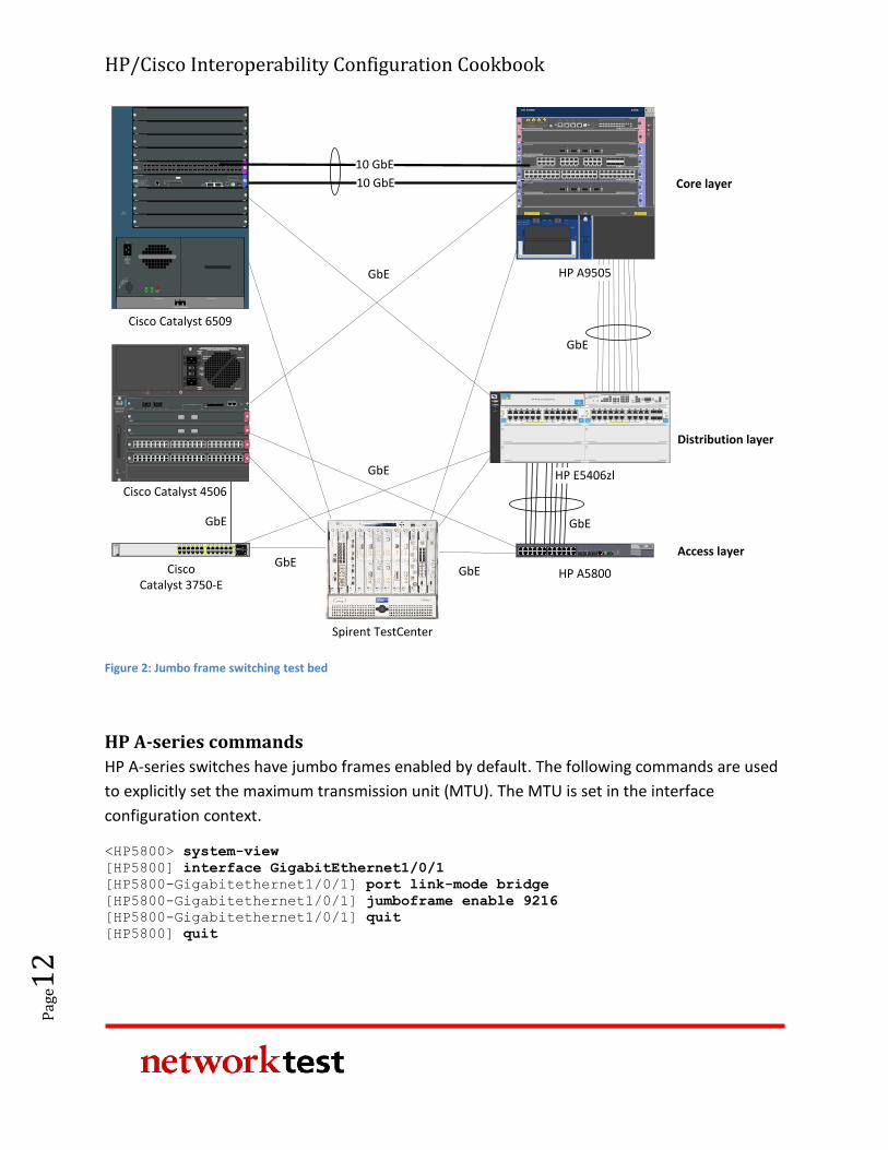
Figure 2 below illustrates the configuration used to validate jumbo frame switching. This test
deviates from the standard test bed by the removal of the link aggregation trunks between the
Cisco Catalyst 4506 and the Cisco Catalyst 3750-E as well as the link aggregation trunk between
the Cisco Catalyst 4506 and the Cisco Catalyst 6509. There is also no connection between the
Cisco Catalyst 4506 and the Cisco Catalyst 6509. As noted in the configuration sections below,
all interfaces explicitly support switching of jumbo frames. Engineers configured all interswitch
trunks to use VLAN trunking, in this case carrying traffic from VLAN 300.
HP/Cisco Interoperability Configuration Cookbook
Pag
e12
10 GbE
FANSTATUS
1
2
3
4
5
6
7
8
9
Power Supply 1 Power Supply 2
Catalyst 6500 SERIES
Cisco Catalyst 6509
100-240 V~16 A
60/50 Hz
INPUTOK
FANOK
OUTPUTFAIL
RUNIN
STALL
INPUT
WS-X6748-SFP
48 PORT GIGABIT ETHERNET SFP
STATUS
1 2 3 4 5 6 7 8 9 10 11 12 13 14 15 16 17 18 19 20 21 22 23 24 25 26 27 28 29 30 31 32 33 34 35 36 37 38 39 40 41 42 43 44 45 46 47 48
WS-SUP32-10GE-P3B
CATALYST 6500 SUPERVISOR ENGINE 32
SYSTEM
STATU
S
ACTIV
E
PWR
MG
MT
EJECT
DISK 0CONSOLEPORT 2PORT 1
LINK 1
LINK 2
RESET
TX RX TX RX
LINK
USB 2.0
PORT 3
E S D
This device has more than one power
input. DO disconnect all power inputs
to power off this device.
High leakage current,earth
connection essential before
connecting power supply.PWR2PWR1 POE
RUN
ALM
FAN
0
6
5
4
3
2
1
UP
H3C S9505E
POWER 1: ~100-240V;50/60Hz;16A
POWER 2: ~100-240V;50/60Hz;16A
POWER 1
POWER 2
ON1 OFF1 ON2 OFF2
10GBASE-R/W-XFP
21LINK
ACT
LINK
ACT
LSR1XP2LEB1
CF CARD
CLKIN
CLKO
UT C
FS
MG
MNT
ACT
LINK
RS232/485
CO
NSO
LE
AUX
RESET
USB
DEV U
SBS
HO
ST
LSR1SRP2C1
ALM
SFSAC
TRUN
LPU
5 6 7 8 90 1 2 3 4 10 11 12 13
LSR2GV48REB110/100/1000BASE-T-RJ45
1 2 3 4 5 6 7 8 9 10 11 12 13 14 15 16 17 18 19 20 21 22 23 24 25 26 27 28 29 30 31 32 33 34 35 36 37 38 39 40 41 42 43 44 45 46 47 48
48
47
2
1
15
16
17
18
31
32
33
34 LINK/ACTLINK/ACT
LINK/ACT
1 2 3 4 5 6 7 8 9 10 11 12 13 14 15 16 17 18 19 20 21 22 23 24
LINK/ACT
25 26 27 28 29 30 31 32
LSR1GT24LEC110/100/1000BASE-T-RJ45 COMBO
8
7
2
1
16
15
10
9
24
23
18
17
26
25
32
31
10GBASE-R/W-XFP LSR1XP4LEC1
3 421LINK
ACT
LINK
ACT
LINK
ACT
LINK
ACT
10GBASE-R/W-XFP
3 421LINK
ACT
LINK
ACT
LINK
ACT
LINK
ACT
LSR1XP4LEB1
H3C S5800 Series
SFP+10/100/1000Base-T
Speed:Green = 1000Mbps, Yellow = 10/100Mbps
Console
11 129 107 85 63 41 2 13 14 15 16 17 18 19 20 21 22 23 24
25 26 27 28
Green=10Gbps, Yellow=1Gbps
Duplex: Green=Full Duplex, Yellow =Half Duplex
SYS
RPS
SLOT1
Mode
Y ellow = Duplex
UnitGreen = Speed
zlmodule
ModuleStatus
ModuleLocator
HDDActivityModule
Shutdown
NetworkActivity
ONE Services Module
USB
Link/Act
Managment10/100/1000T
PCIe 1
PCIe 2
Avaya Aura SBCpowered by Acme Packet
TM
HP ONEExt Svcszl ModuleJ9543A
zlmodule
ModuleStatus
ModuleLocator
HDDActivityModule
Shutdown
NetworkActivity
ONE Services Module
USB
Link/Act
Managment10/100/1000T
PCIe 1
PCIe 2
Avaya Aura SBCpowered by Acme Packet
TM
HP ONEExt Svcszl ModuleJ9543A
C I S C OSYST
RPS
STAT
DUPLX
SPEED
MODE
1X
2X
11X
12X
1 2 3 4 5 6 7 8 9 10 11 12
25
X2-1
X2-2
MASTER
STACK
Catalyst 3750-E Series-24
27
26
28
13X
14X
23X
24X
13 14 15 16 17 18 19 20 21 22 23 24
Cisco Catalyst 3750-E
Spirent TestCenter
1
2
3
4
5
6
SU
PE
RV
ISO
R
Catalyst
4506-E
1
2
3
4
5
6FAN
STATUS
SU
PE
RV
ISO
R
Catalyst
4506-E
SWITCHED SHOULD BE IN THE OFF ‘O’ POSITION TO INSTALL /
REMOVE POWER SUPPLIES. FASTENERS MUST BE FULLY ENGAGED
PRIOR TO OPERATING POWER SUPPLY
100-240V~
12A
50/60Hz
OUTPUT FAIL
INPUT 1
OK
INPUT 2
OK
100-240V~
12A
50/60Hz
POE ENABLED
4200ACV
FAN OK
RESET
UPLINK 1 UPLINK 2
ACTIVELINK LINK ACTIVE ACTIVE
WS-X4516 SUPERVISOR ENGINE V
STATUS
EJECT
FLASH
CONSOLE
LINK
MGT10/100
UTILIZATION
100%1%
1000 BASE-X
STATUS
WS-X4302-GB
21
SWITCHING MODULE
1000 BASE-X
STATUS
WS-X4302-GB
21
SWITCHING MODULE
MAX 15.4W/PORT
STATUS
WS-X4548-GB-RJ45V
1 2 3 4 5 6 7 8 9 10 11 12 13 14 15 16
MULTI-SPEEDGIGABIT ETHERNET
SWITCHING MODULE
48-PORT10/100/1000 BASE T
IN-LINE POWER
3231
3029
2827
2625
2423
2221
2019
1817
4847
4645
4443
4241
4039
3837
3635
3433
1615
1413
1211
109
87
65
43
21
32313029282726252423222120191817 33 34 35 36 37 38 39 40 41 42 43 44 45 46 47 48
MAX 15.4W/PORT
STATUS
WS-X4548-GB-RJ45V
1 2 3 4 5 6 7 8 9 10 11 12 13 14 15 16
MULTI-SPEEDGIGABIT ETHERNET
SWITCHING MODULE
48-PORT10/100/1000 BASE T
IN-LINE POWER
3231
3029
2827
2625
2423
2221
2019
1817
4847
4645
4443
4241
4039
3837
3635
3433
1615
1413
1211
109
87
65
43
21
32313029282726252423222120191817 33 34 35 36 37 38 39 40 41 42 43 44 45 46 47 48
HP A5800
HP A9505
Cisco Catalyst 4506
Power
Fault
Locator
E F
C D
A
ProCurve NetworkingHP Innovation
zlProCurve
24p Gig-T
zl Module
J8702A PoE-Integrated 10/100/1000Base-T Ports (1-24) - Ports are IEEE Auto MDI/MDI-X
1 5
62
3
4
7 11
128
9
10
13 17
1814
15
16
19 23
2420
21
22 zlProCurve
24p Gig-T
zl Module
J8702A PoE-Integrated 10/100/1000Base-T Ports (1-24) - Ports are IEEE Auto MDI/MDI-X
1 5
62
3
4
7 11
128
9
10
13 17
1814
15
16
19 23
2420
21
22
ConsoleReset Clear
Auxiliary Port
ProCurve Switch 5400zl
Management Module
J8726A
Internal
PowerPoE
Pwr
2
1
2
4
1
3
PoE
Temp
Fan
Flash
DIMM
Mgmt
ChasTest
LED ModeModules
Status
Act
FDx
Spd Usr
PoE
H
J
LK
I
G
F
D
B
E
C
A
ProCurve
Switch 5406zl
J8699A PoE
Use
zl Modules
only
B
ProCurve
Switch 5406zl
J9447A
zlProCurve
Gig-T/SFP
zl Module
J9308A PoE-Integrated 10/100/1000Base-T Ports (1-24) - Ports are Auto MDIX
1 5
62
3
4
7 11
128
9
10
13 17
1814
15
16
19
20
23
24
21
22
Use only
HP ProCurve
SFPs
zlProCurve
Gig-T PoE+
zl Module
J9307A PoE-Integrated 10/100/1000Base-T Ports (1-24) - Ports are Auto MDIX
1 5
62
3
4
7 11
128
9
10
13 17
1814
15
16
19 23
2420
21
22
HP ProCurve Networking
HP E5406zl
GbE
GbE
GbE
GbEGbE
GbEGbE
Core layer
Distribution layer
Access layer
10 GbE
Figure 2: Jumbo frame switching test bed
HP A-series commands
HP A-series switches have jumbo frames enabled by default. The following commands are used
to explicitly set the maximum transmission unit (MTU). The MTU is set in the interface
configuration context.
<HP5800> system-view
[HP5800] interface GigabitEthernet1/0/1
[HP5800-Gigabitethernet1/0/1] port link-mode bridge
[HP5800-Gigabitethernet1/0/1] jumboframe enable 9216
[HP5800-Gigabitethernet1/0/1] quit
[HP5800] quit
HP/Cisco Interoperability Configuration Cookbook
Pag
e13
HP E-series commands
HP E-series switches set the MTU on a per-VLAN basis. When enabled, all ports on that VLAN
will forward jumbo frames.
HP5406ZL# configure
HP5406ZL(config)# vlan 300
HP5406ZL(vlan-300)# name "VLAN306"
HP5406ZL(vlan-300)# untagged A1-A5,A9-A10,Trk1-Trk2
HP5406ZL(vlan-300)# ip address 10.1.2.1 255.255.0.0
HP5406ZL(vlan-300)# jumbo
HP5406ZL(vlan-300)# exit
HP5406ZL(config)# exit
Cisco commands
On Cisco Catalyst 6509 and Cisco Catalyst 4506 switches, jumbo frame support varies by line
card. For line cards that support jumbo frames, MTU is set on a per-interface basis.
Cat6509# configure terminal
Cat6509(config)# interface GigabitEthernet4/48
Cat6509(config-if)# switchport
Cat6509(config-if)# switchport access vlan 300
Cat6509(config-if)# switchport mode access
Cat6509(config-if)# mtu 9216
Cat6509(config-if)# end
On Cisco Catalyst 3750-E switches, MTU is set systemwide:
Cat3750E# configure terminal
Cat3750E(config)# system mtu jumbo 9216
Cat3750E(config)# end
Validation
Generating jumbo frames between the attached clients and servers will validate the ability of
the switches to exchange jumbo traffic. All switches will forward all jumbo frames with zero
frame loss.
HP/Cisco Interoperability Configuration Cookbook
Pag
e14
Jumbo frame routing
Objective
To validate the ability of HP Networking and Cisco Catalyst switches to correctly route
bidirectional traffic consisting of jumbo frames.
Background
Some routing protocols, such as open shortest path first (OSPF), require that both routers use
the same MTU before exchanging routing information. For Ethernet interfaces, the requirement
for matched MTUs applies equally to jumbo frames (those larger than 1518 bytes) as to
standard-length frames.
HP Networking and Cisco Catalyst switches both support 9,216-byte jumbo frames, including
Ethernet CRC. This section explains how to configure both vendors’ devices to set up on an
OSPF routing session using jumbo frames.
Topology
In this example, the HP A9505, HP E5406zl, and HP A5800 switches are configured as OSPF
routers exchanging jumbo frames with Cisco Catalyst 6509, Cisco Catalyst 4506, and Cisco
Catalyst 3750-E switches.
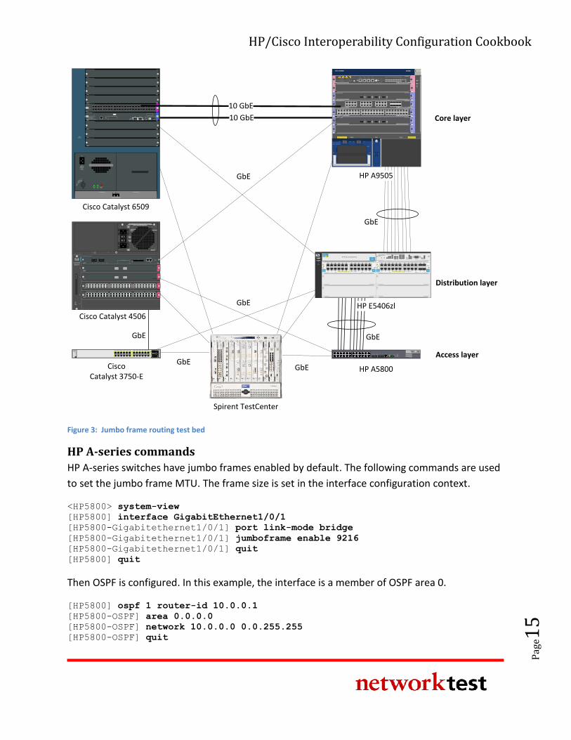
Figure 3 below illustrates the configuration used to validate jumbo frame routing. This test
deviates from the standard test bed by the removal of the link aggregation trunks between the
Cisco Catalyst 4506 and the Cisco Catalyst 3750-E, and between the Cisco Catalyst 4506 and the
Cisco Catalyst 6509. There is also no connection between the Cisco Catalyst 4506 and the Cisco
Catalyst 6509. In addition, all devices routed traffic at layer 3 in this test. In this example, OSPF
routing sessions are established between all connected devices.
HP/Cisco Interoperability Configuration Cookbook
Pag
e15
10 GbE
FANSTATUS
1
2
3
4
5
6
7
8
9
Power Supply 1 Power Supply 2
Catalyst 6500 SERIES
Cisco Catalyst 6509
100-240 V~16 A
60/50 Hz
INPUTOK
FANOK
OUTPUTFAIL
RUNIN
STALL
INPUT
WS-X6748-SFP
48 PORT GIGABIT ETHERNET SFP
STATUS
1 2 3 4 5 6 7 8 9 10 11 12 13 14 15 16 17 18 19 20 21 22 23 24 25 26 27 28 29 30 31 32 33 34 35 36 37 38 39 40 41 42 43 44 45 46 47 48
WS-SUP32-10GE-P3B
CATALYST 6500 SUPERVISOR ENGINE 32
SYSTEM
STATU
S
ACTIV
E
PWR
MG
MT
EJECT
DISK 0CONSOLEPORT 2PORT 1
LINK 1
LINK 2
RESET
TX RX TX RX
LINK
USB 2.0
PORT 3
E S D
This device has more than one power
input. DO disconnect all power inputs
to power off this device.
High leakage current,earth
connection essential before
connecting power supply.PWR2PWR1 POE
RUN
ALM
FAN
0
6
5
4
3
2
1
UP
H3C S9505E
POWER 1: ~100-240V;50/60Hz;16A
POWER 2: ~100-240V;50/60Hz;16A
POWER 1
POWER 2
ON1 OFF1 ON2 OFF2
10GBASE-R/W-XFP
21LINK
ACT
LINK
ACT
LSR1XP2LEB1
CF CARD
CLKIN
CLKO
UT C
FS
MG
MNT
ACT
LINK
RS232/485
CO
NSO
LE
AUX
RESET
USB
DEV U
SBS
HO
ST
LSR1SRP2C1
ALM
SFSAC
TRUN
LPU
5 6 7 8 90 1 2 3 4 10 11 12 13
LSR2GV48REB110/100/1000BASE-T-RJ45
1 2 3 4 5 6 7 8 9 10 11 12 13 14 15 16 17 18 19 20 21 22 23 24 25 26 27 28 29 30 31 32 33 34 35 36 37 38 39 40 41 42 43 44 45 46 47 48
48
47
2
1
15
16
17
18
31
32
33
34 LINK/ACTLINK/ACT
LINK/ACT
1 2 3 4 5 6 7 8 9 10 11 12 13 14 15 16 17 18 19 20 21 22 23 24
LINK/ACT
25 26 27 28 29 30 31 32
LSR1GT24LEC110/100/1000BASE-T-RJ45 COMBO
8
7
2
1
16
15
10
9
24
23
18
17
26
25
32
31
10GBASE-R/W-XFP LSR1XP4LEC1
3 421LINK
ACT
LINK
ACT
LINK
ACT
LINK
ACT
10GBASE-R/W-XFP
3 421LINK
ACT
LINK
ACT
LINK
ACT
LINK
ACT
LSR1XP4LEB1
H3C S5800 Series
SFP+10/100/1000Base-T
Speed:Green = 1000Mbps, Yellow = 10/100Mbps
Console
11 129 107 85 63 41 2 13 14 15 16 17 18 19 20 21 22 23 24
25 26 27 28
Green=10Gbps, Yellow=1Gbps
Duplex: Green=Full Duplex, Yellow =Half Duplex
SYS
RPS
SLOT1
Mode
Y ellow = Duplex
UnitGreen = Speed
zlmodule
ModuleStatus
ModuleLocator
HDDActivityModule
Shutdown
NetworkActivity
ONE Services Module
USB
Link/Act
Managment10/100/1000T
PCIe 1
PCIe 2
Avaya Aura SBCpowered by Acme Packet
TM
HP ONEExt Svcszl ModuleJ9543A
zlmodule
ModuleStatus
ModuleLocator
HDDActivityModule
Shutdown
NetworkActivity
ONE Services Module
USB
Link/Act
Managment10/100/1000T
PCIe 1
PCIe 2
Avaya Aura SBCpowered by Acme Packet
TM
HP ONEExt Svcszl ModuleJ9543A
C I S C OSYST
RPS
STAT
DUPLX
SPEED
MODE
1X
2X
11X
12X
1 2 3 4 5 6 7 8 9 10 11 12
25
X2-1
X2-2
MASTER
STACK
Catalyst 3750-E Series-24
27
26
28
13X
14X
23X
24X
13 14 15 16 17 18 19 20 21 22 23 24
Cisco Catalyst 3750-E
Spirent TestCenter
1
2
3
4
5
6
SU
PE
RV
ISO
R
Catalyst
4506-E
1
2
3
4
5
6FAN
STATUS
SU
PE
RV
ISO
R
Catalyst
4506-E
SWITCHED SHOULD BE IN THE OFF ‘O’ POSITION TO INSTALL /
REMOVE POWER SUPPLIES. FASTENERS MUST BE FULLY ENGAGED
PRIOR TO OPERATING POWER SUPPLY
100-240V~
12A
50/60Hz
OUTPUT FAIL
INPUT 1
OK
INPUT 2
OK
100-240V~
12A
50/60Hz
POE ENABLED
4200ACV
FAN OK
RESET
UPLINK 1 UPLINK 2
ACTIVELINK LINK ACTIVE ACTIVE
WS-X4516 SUPERVISOR ENGINE V
STATUS
EJECT
FLASH
CONSOLE
LINK
MGT10/100
UTILIZATION
100%1%
1000 BASE-X
STATUS
WS-X4302-GB
21
SWITCHING MODULE
1000 BASE-X
STATUS
WS-X4302-GB
21
SWITCHING MODULE
MAX 15.4W/PORT
STATUS
WS-X4548-GB-RJ45V
1 2 3 4 5 6 7 8 9 10 11 12 13 14 15 16
MULTI-SPEEDGIGABIT ETHERNET
SWITCHING MODULE
48-PORT10/100/1000 BASE T
IN-LINE POWER
3231
3029
2827
2625
2423
2221
2019
1817
4847
4645
4443
4241
4039
3837
3635
3433
1615
1413
1211
109
87
65
43
21
32313029282726252423222120191817 33 34 35 36 37 38 39 40 41 42 43 44 45 46 47 48
MAX 15.4W/PORT
STATUS
WS-X4548-GB-RJ45V
1 2 3 4 5 6 7 8 9 10 11 12 13 14 15 16
MULTI-SPEEDGIGABIT ETHERNET
SWITCHING MODULE
48-PORT10/100/1000 BASE T
IN-LINE POWER
3231
3029
2827
2625
2423
2221
2019
1817
4847
4645
4443
4241
4039
3837
3635
3433
1615
1413
1211
109
87
65
43
21
32313029282726252423222120191817 33 34 35 36 37 38 39 40 41 42 43 44 45 46 47 48
HP A5800
HP A9505
Cisco Catalyst 4506
Power
Fault
Locator
E F
C D
A
ProCurve NetworkingHP Innovation
zlProCurve
24p Gig-T
zl Module
J8702A PoE-Integrated 10/100/1000Base-T Ports (1-24) - Ports are IEEE Auto MDI/MDI-X
1 5
62
3
4
7 11
128
9
10
13 17
1814
15
16
19 23
2420
21
22 zlProCurve
24p Gig-T
zl Module
J8702A PoE-Integrated 10/100/1000Base-T Ports (1-24) - Ports are IEEE Auto MDI/MDI-X
1 5
62
3
4
7 11
128
9
10
13 17
1814
15
16
19 23
2420
21
22
ConsoleReset Clear
Auxiliary Port
ProCurve Switch 5400zl
Management Module
J8726A
Internal
PowerPoE
Pwr
2
1
2
4
1
3
PoE
Temp
Fan
Flash
DIMM
Mgmt
ChasTest
LED ModeModules
Status
Act
FDx
Spd Usr
PoE
H
J
LK
I
G
F
D
B
E
C
A
ProCurve
Switch 5406zl
J8699A PoE
Use
zl Modules
only
B
ProCurve
Switch 5406zl
J9447A
zlProCurve
Gig-T/SFP
zl Module
J9308A PoE-Integrated 10/100/1000Base-T Ports (1-24) - Ports are Auto MDIX
1 5
62
3
4
7 11
128
9
10
13 17
1814
15
16
19
20
23
24
21
22
Use only
HP ProCurve
SFPs
zlProCurve
Gig-T PoE+
zl Module
J9307A PoE-Integrated 10/100/1000Base-T Ports (1-24) - Ports are Auto MDIX
1 5
62
3
4
7 11
128
9
10
13 17
1814
15
16
19 23
2420
21
22
HP ProCurve Networking
HP E5406zl
GbE
GbE
GbE
GbEGbE
GbEGbE
Core layer
Distribution layer
Access layer
10 GbE
Figure 3: Jumbo frame routing test bed
HP A-series commands
HP A-series switches have jumbo frames enabled by default. The following commands are used
to set the jumbo frame MTU. The frame size is set in the interface configuration context.
<HP5800> system-view
[HP5800] interface GigabitEthernet1/0/1
[HP5800-Gigabitethernet1/0/1] port link-mode bridge
[HP5800-Gigabitethernet1/0/1] jumboframe enable 9216
[HP5800-Gigabitethernet1/0/1] quit
[HP5800] quit
Then OSPF is configured. In this example, the interface is a member of OSPF area 0.
[HP5800] ospf 1 router-id 10.0.0.1
[HP5800-OSPF] area 0.0.0.0
[HP5800-OSPF] network 10.0.0.0 0.0.255.255
[HP5800-OSPF] quit
HP/Cisco Interoperability Configuration Cookbook
Pag
e16
HP E-series commands
HP E-series switches set MTU on a per-VLAN basis. When enabled, all ports on that VLAN will
forward jumbo frames.
HP5406ZL# configure
HP5406ZL(config)# vlan 300
HP5406ZL(vlan-300)# name "VLAN306"
HP5406ZL(vlan-300)# untagged A1-A5,A9-A10,Trk1-Trk2
HP5406ZL(vlan-300)# ip address 10.1.2.1 255.255.0.0
HP5406ZL(vlan-300)# jumbo
HP5406ZL(vlan-300)# exit
Then set up OSPF routing. In our configuration, the VLAN interfaces were used as the routable
interfaces. The area backbone command designates OSPF area 0.
HP5406(config)# ip routing
HP5406(config)# ip router-id 10.0.32.1
HP5406(config)# router ospf
HP5406(ospf)# area backbone range 10.0.0.0 255.255.0.0 type summary
HP5406(ospf)# exit
HP5406(config)# vlan 33
HP5406(vlan-33)# ip ospf 10.0.33.1 area backbone
HP5406(vlan-33)# exit
HP5406(config)# vlan 34
HP5406(vlan-34)# ip ospf 10.0.34.1 area backbone
HP5406(vlan-34)# exit
HP5406(config)# vlan 35
HP5406(vlan-35)# ip ospf 10.0.35.1 area backbone
HP5406(vlan-35)# exit
HP5406(config)# vlan 36
HP5406(vlan-36)# ip ospf 10.0.36.1 area backbone
HP5406(vlan-36)# exit
HP5406(config)# vlan 37
HP5406(vlan-37)# ip ospf 10.0.37.1 area backbone
HP5406(vlan-37)#
HP5406(config)# vlan 38
HP5406(vlan-38)# ip ospf 10.0.38.1 area backbone
HP5406(vlan-38)# exit
HP5406(config)# vlan 39
HP5406(vlan-39)# ip ospf 10.0.39.1 area backbone
HP5406(vlan-39)# exit
HP5406(config)# vlan 40
HP5406(vlan-40)# ip ospf 10.0.40.1 area backbone
HP5406(vlan-40)# exit
HP5406(config)# exit
Cisco commands
On Cisco Catalyst 6509 and Cisco Catalyst 4506 switches, jumbo frame support varies by line
card. For those line cards that support jumbo frames, MTU is set on a per-interface basis. Cisco
HP/Cisco Interoperability Configuration Cookbook
Pag
e17
IOS has separate commands for mtu, describing the maximum transmission unit for the
Ethernet frame and for the ip mtu, describing the MTU for the IP packet.
Configure the interface with a jumbo frame size.
Cat6509# configure terminal
Cat6509(config)# interface GigabitEthernet4/9
Cat6509(config-if)# ip address 10.0.42.2 255.255.255.0
Cat6509(config-if)# ip mtu 9198
Cat6509(config-if)# exit
Then set up OSPF.
Cat6509(config)# router ospf 1
Cat6509(config-router)# log-adjacency-changes
Cat6509(config-router)# network 10.0.0.0 0.0.255.255 area 0
Cat6509(config-router)# exit
Then set up the VLAN for jumbo frames. This is required to route jumbo frames between
VLANs. All interfaces in the VLAN must be set to allow jumbo frames before this command will
take effect.
Cat6509(config)# interface Vlan193
Cat6509(config-if)# mtu 9216
Cat6509(config-if)# end
On Cisco Catalyst 3750-E switches, MTU is set systemwide:
Cat3750E# configure terminal
Cat3750E(config)# system mtu jumbo 9216
Cat3750E(config)# system mtu routing 9198
Cat3750E(config)# router ospf 1
Cat3750E(config-router)# log-adjacency-changes
Cat3750E(config-router)# network 10.0.43.2 0.0.0.0 area 0
Cat3750E(config-router)# network 10.0.75.2 0.0.0.0 area 0
Cat3750E(config-router)# network 10.0.128.0 0.0.127.255 area 0
Cat3750E(config-router)# network 192.168.1.0 0.0.0.255 area 0
Cat3750E(config-router)# network 192.168.2.0 0.0.0.255 area 0
Cat3750E(config-router)# end
Validation
Unless both HP and Cisco interfaces agree on MTU size, OSPF routing adjacencies will remain in
ExStart state, and will never transition to OSPF “full” state. To verify that an OSPF adjacency has
entered OSPF “full” state on the HP A-series switches, use the display ospf peer
command. To verify that an OSPF adjacency has entered OSPF “full” state on HP E-series and
Cisco switches, use the show ip ospf neighbor command.
HP/Cisco Interoperability Configuration Cookbook
Pag
e18
The fact that both routers are in Full state indicates they have agreed to exchange IP packets up
to 9,198 bytes long (or 9,216 bytes, including Ethernet header and CRC). OSPF routing session
establishment will not work unless both sides agree on MTU size.
Link aggregation
Objective
To validate the ability of HP Networking and Cisco Catalyst switches to correctly forward traffic
over a logical connection created using IEEE 802.3ad link aggregation.
Background
The IEEE 802.3ad link specification defines a standards-based method for aggregating multiple
physical Ethernet links into a single logical link. The logical link, known as a link aggregation
group (LAG), is comprised of multiple members (pairs of physical interfaces on each switch).
LAGs may be defined statically or dynamically, the latter using the link aggregation control
protocol (LACP). With LACP enabled, 802.3ad-compliant switches can dynamically add or
remove up to eight LAG members.
Link aggregation is useful both for increasing bandwidth beyond the limits of single physical
interfaces and, especially when used with LACP, for adding redundancy to network connections.
Topology
In this example, an HP A9505 switch uses two-member LAGs to exchange traffic with a Cisco
Catalyst 6509 switch and a Cisco Catalyst 4506 switch. An HP E5406zl switch uses two-member
LAGs to exchange traffic with a Cisco Catalyst 6509 switch and a Cisco Catalyst 3750-E switch.
An HP A5800 switch uses two-member LAGs to exchange traffic with a Cisco Catalyst 4506
switch.
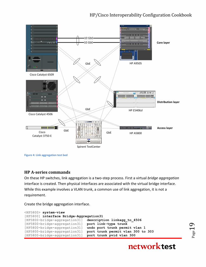
Figure 4 below shows the topology used to validate link aggregation and LACP functionality.
This test deviates from the standard test bed with the additional of several link aggregation
groups between the HP E5406zl and the Cisco Catalyst 3750-E, between the HP 5406zl and the
Cisco Catalyst 6509, between the HP A9505 and the Cisco Catalyst 4506, and between the HP
5800 and the Cisco C5406. Other connections have been removed between the HP 5406zl and
the HP 5800, between the HP 5406zl and HP 9505, between the Cisco Catalyst 3750-E and the
Cisco Catalyst 4506, and between the Cisco Catalyst 4506 and the Cisco Catalyst 6509.
HP/Cisco Interoperability Configuration Cookbook
Pag
e19
FANSTATUS
1
2
3
4
5
6
7
8
9
Power Supply 1 Power Supply 2
Catalyst 6500 SERIES
Cisco Catalyst 6509
100-240 V~16 A
60/50 Hz
INPUTOK
FANOK
OUTPUTFAIL
RUNIN
STALL
INPUT
WS-X6748-SFP
48 PORT GIGABIT ETHERNET SFP
STATUS
1 2 3 4 5 6 7 8 9 10 11 12 13 14 15 16 17 18 19 20 21 22 23 24 25 26 27 28 29 30 31 32 33 34 35 36 37 38 39 40 41 42 43 44 45 46 47 48
WS-SUP32-10GE-P3B
CATALYST 6500 SUPERVISOR ENGINE 32
SYSTEM
STATU
S
ACTIV
E
PWR
MG
MT
EJECT
DISK 0CONSOLEPORT 2PORT 1
LINK 1
LINK 2
RESET
TX RX TX RX
LINK
USB 2.0
PORT 3
E S D
This device has more than one power
input. DO disconnect all power inputs
to power off this device.
High leakage current,earth
connection essential before
connecting power supply.PWR2PWR1 POE
RUN
ALM
FAN
0
6
5
4
3
2
1
UP
H3C S9505E
POWER 1: ~100-240V;50/60Hz;16A
POWER 2: ~100-240V;50/60Hz;16A
POWER 1
POWER 2
ON1 OFF1 ON2 OFF2
10GBASE-R/W-XFP
21LINK
ACT
LINK
ACT
LSR1XP2LEB1
CF CARD
CLKIN
CLKO
UT C
FS
MG
MNT
ACT
LINK
RS232/485
CO
NSO
LE
AUX
RESET
USB
DEV U
SBS
HO
ST
LSR1SRP2C1
ALM
SFSAC
TRUN
LPU
5 6 7 8 90 1 2 3 4 10 11 12 13
LSR2GV48REB110/100/1000BASE-T-RJ45
1 2 3 4 5 6 7 8 9 10 11 12 13 14 15 16 17 18 19 20 21 22 23 24 25 26 27 28 29 30 31 32 33 34 35 36 37 38 39 40 41 42 43 44 45 46 47 48
48
47
2
1
15
16
17
18
31
32
33
34 LINK/ACTLINK/ACT
LINK/ACT
1 2 3 4 5 6 7 8 9 10 11 12 13 14 15 16 17 18 19 20 21 22 23 24
LINK/ACT
25 26 27 28 29 30 31 32
LSR1GT24LEC110/100/1000BASE-T-RJ45 COMBO
8
7
2
1
16
15
10
9
24
23
18
17
26
25
32
31
10GBASE-R/W-XFP LSR1XP4LEC1
3 421LINK
ACT
LINK
ACT
LINK
ACT
LINK
ACT
10GBASE-R/W-XFP
3 421LINK
ACT
LINK
ACT
LINK
ACT
LINK
ACT
LSR1XP4LEB1
H3C S5800 Series
SFP+10/100/1000Base-T
Speed:Green = 1000Mbps, Yellow = 10/100Mbps
Console
11 129 107 85 63 41 2 13 14 15 16 17 18 19 20 21 22 23 24
25 26 27 28
Green=10Gbps, Yellow=1Gbps
Duplex: Green=Full Duplex, Yellow =Half Duplex
SYS
RPS
SLOT1
Mode
Y ellow = Duplex
UnitGreen = Speed
zlmodule
ModuleStatus
ModuleLocator
HDDActivityModule
Shutdown
NetworkActivity
ONE Services Module
USB
Link/Act
Managment10/100/1000T
PCIe 1
PCIe 2
Avaya Aura SBCpowered by Acme Packet
TM
HP ONEExt Svcszl ModuleJ9543A
zlmodule
ModuleStatus
ModuleLocator
HDDActivityModule
Shutdown
NetworkActivity
ONE Services Module
USB
Link/Act
Managment10/100/1000T
PCIe 1
PCIe 2
Avaya Aura SBCpowered by Acme Packet
TM
HP ONEExt Svcszl ModuleJ9543A
C I S C OSYST
RPS
STAT
DUPLX
SPEED
MODE
1X
2X
11X
12X
1 2 3 4 5 6 7 8 9 10 11 12
25
X2-1
X2-2
MASTER
STACK
Catalyst 3750-E Series-24
27
26
28
13X
14X
23X
24X
13 14 15 16 17 18 19 20 21 22 23 24
Cisco Catalyst 3750-E
Spirent TestCenter
1
2
3
4
5
6
SU
PE
RV
ISO
R
Catalyst
4506-E
1
2
3
4
5
6FAN
STATUS
SU
PE
RV
ISO
R
Catalyst
4506-E
SWITCHED SHOULD BE IN THE OFF ‘O’ POSITION TO INSTALL /
REMOVE POWER SUPPLIES. FASTENERS MUST BE FULLY ENGAGED
PRIOR TO OPERATING POWER SUPPLY
100-240V~
12A
50/60Hz
OUTPUT FAIL
INPUT 1
OK
INPUT 2
OK
100-240V~
12A
50/60Hz
POE ENABLED
4200ACV
FAN OK
RESET
UPLINK 1 UPLINK 2
ACTIVELINK LINK ACTIVE ACTIVE
WS-X4516 SUPERVISOR ENGINE V
STATUS
EJECT
FLASH
CONSOLE
LINK
MGT10/100
UTILIZATION
100%1%
1000 BASE-X
STATUS
WS-X4302-GB
21
SWITCHING MODULE
1000 BASE-X
STATUS
WS-X4302-GB
21
SWITCHING MODULE
MAX 15.4W/PORT
STATUS
WS-X4548-GB-RJ45V
1 2 3 4 5 6 7 8 9 10 11 12 13 14 15 16
MULTI-SPEEDGIGABIT ETHERNET
SWITCHING MODULE
48-PORT10/100/1000 BASE T
IN-LINE POWER
3231
3029
2827
2625
2423
2221
2019
1817
4847
4645
4443
4241
4039
3837
3635
3433
1615
1413
1211
109
87
65
43
21
32313029282726252423222120191817 33 34 35 36 37 38 39 40 41 42 43 44 45 46 47 48
MAX 15.4W/PORT
STATUS
WS-X4548-GB-RJ45V
1 2 3 4 5 6 7 8 9 10 11 12 13 14 15 16
MULTI-SPEEDGIGABIT ETHERNET
SWITCHING MODULE
48-PORT10/100/1000 BASE T
IN-LINE POWER
3231
3029
2827
2625
2423
2221
2019
1817
4847
4645
4443
4241
4039
3837
3635
3433
1615
1413
1211
109
87
65
43
21
32313029282726252423222120191817 33 34 35 36 37 38 39 40 41 42 43 44 45 46 47 48
HP A5800
HP A9505
Cisco Catalyst 4506
Power
Fault
Locator
E F
C D
A
ProCurve NetworkingHP Innovation
zlProCurve
24p Gig-T
zl Module
J8702A PoE-Integrated 10/100/1000Base-T Ports (1-24) - Ports are IEEE Auto MDI/MDI-X
1 5
62
3
4
7 11
128
9
10
13 17
1814
15
16
19 23
2420
21
22 zlProCurve
24p Gig-T
zl Module
J8702A PoE-Integrated 10/100/1000Base-T Ports (1-24) - Ports are IEEE Auto MDI/MDI-X
1 5
62
3
4
7 11
128
9
10
13 17
1814
15
16
19 23
2420
21
22
ConsoleReset Clear
Auxiliary Port
ProCurve Switch 5400zl
Management Module
J8726A
Internal
PowerPoE
Pwr
2
1
2
4
1
3
PoE
Temp
Fan
Flash
DIMM
Mgmt
ChasTest
LED ModeModules
Status
Act
FDx
Spd Usr
PoE
H
J
LK
I
G
F
D
B
E
C
A
ProCurve
Switch 5406zl
J8699A PoE
Use
zl Modules
only
B
ProCurve
Switch 5406zl
J9447A
zlProCurve
Gig-T/SFP
zl Module
J9308A PoE-Integrated 10/100/1000Base-T Ports (1-24) - Ports are Auto MDIX
1 5
62
3
4
7 11
128
9
10
13 17
1814
15
16
19
20
23
24
21
22
Use only
HP ProCurve
SFPs
zlProCurve
Gig-T PoE+
zl Module
J9307A PoE-Integrated 10/100/1000Base-T Ports (1-24) - Ports are Auto MDIX
1 5
62
3
4
7 11
128
9
10
13 17
1814
15
16
19 23
2420
21
22
HP ProCurve Networking
HP E5406zl
GbE
GbE
GbEGbE
Core layer
Distribution layer
Access layer
10 GbE
10 GbE
Figure 4: Link aggregation test bed
HP A-series commands
On these HP switches, link aggregation is a two-step process. First a virtual bridge aggregation
interface is created. Then physical interfaces are associated with the virtual bridge interface.
While this example involves a VLAN trunk, a common use of link aggregation, it is not a
requirement.
Create the bridge aggregation interface.
<HP5800> system-view
[HP5800] interface Bridge-Aggregation31
[HP5800-bridge-aggregation31] description linkagg_to_4506
[HP5800-bridge-aggregation31] port link-type trunk
[HP5800-bridge-aggregation31] undo port trunk permit vlan 1
[HP5800-bridge-aggregation31] port trunk permit vlan 300 to 303
[HP5800-bridge-aggregation31] port trunk pvid vlan 300
HP/Cisco Interoperability Configuration Cookbook
Pag
e20
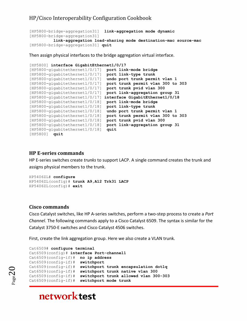
[HP5800-bridge-aggregation31] link-aggregation mode dynamic
[HP5800-bridge-aggregation31]
link-aggregation load-sharing mode destination-mac source-mac
[HP5800-bridge-aggregation31] quit
Then assign physical interfaces to the bridge aggregation virtual interface.
[HP5800] interface GigabitEthernet1/0/17
[HP5800-gigabitethernet1/0/17] port link-mode bridge
[HP5800-gigabitethernet1/0/17] port link-type trunk
[HP5800-gigabitethernet1/0/17] undo port trunk permit vlan 1
[HP5800-gigabitethernet1/0/17] port trunk permit vlan 300 to 303
[HP5800-gigabitethernet1/0/17] port trunk pvid vlan 300
[HP5800-gigabitethernet1/0/17] port link-aggregation group 31
[HP5800-gigabitethernet1/0/17] interface GigabitEthernet1/0/18
[HP5800-gigabitethernet1/0/18] port link-mode bridge
[HP5800-gigabitethernet1/0/18] port link-type trunk
[HP5800-gigabitethernet1/0/18] undo port trunk permit vlan 1
[HP5800-gigabitethernet1/0/18] port trunk permit vlan 300 to 303
[HP5800-gigabitethernet1/0/18] port trunk pvid vlan 300
[HP5800-gigabitethernet1/0/18] port link-aggregation group 31
[HP5800-gigabitethernet1/0/18] quit
[HP5800] quit
HP E-series commands
HP E-series switches create trunks to support LACP. A single command creates the trunk and
assigns physical members to the trunk.
HP5406ZL# configure
HP5406ZL(config)# trunk A9,A12 Trk31 LACP
HP5406ZL(config)# exit
Cisco commands
Cisco Catalyst switches, like HP A-series switches, perform a two-step process to create a Port
Channel. The following commands apply to a Cisco Catalyst 6509. The syntax is similar for the
Catalyst 3750-E switches and Cisco Catalyst 4506 switches.
First, create the link aggregation group. Here we also create a VLAN trunk.
Cat6509# configure terminal
Cat6509(config)# interface Port-channel1
Cat6509(config-if)# no ip address
Cat6509(config-if)# switchport
Cat6509(config-if)# switchport trunk encapsulation dot1q
Cat6509(config-if)# switchport trunk native vlan 300
Cat6509(config-if)# switchport trunk allowed vlan 300-303
Cat6509(config-if)# switchport mode trunk
HP/Cisco Interoperability Configuration Cookbook
Pag
e21
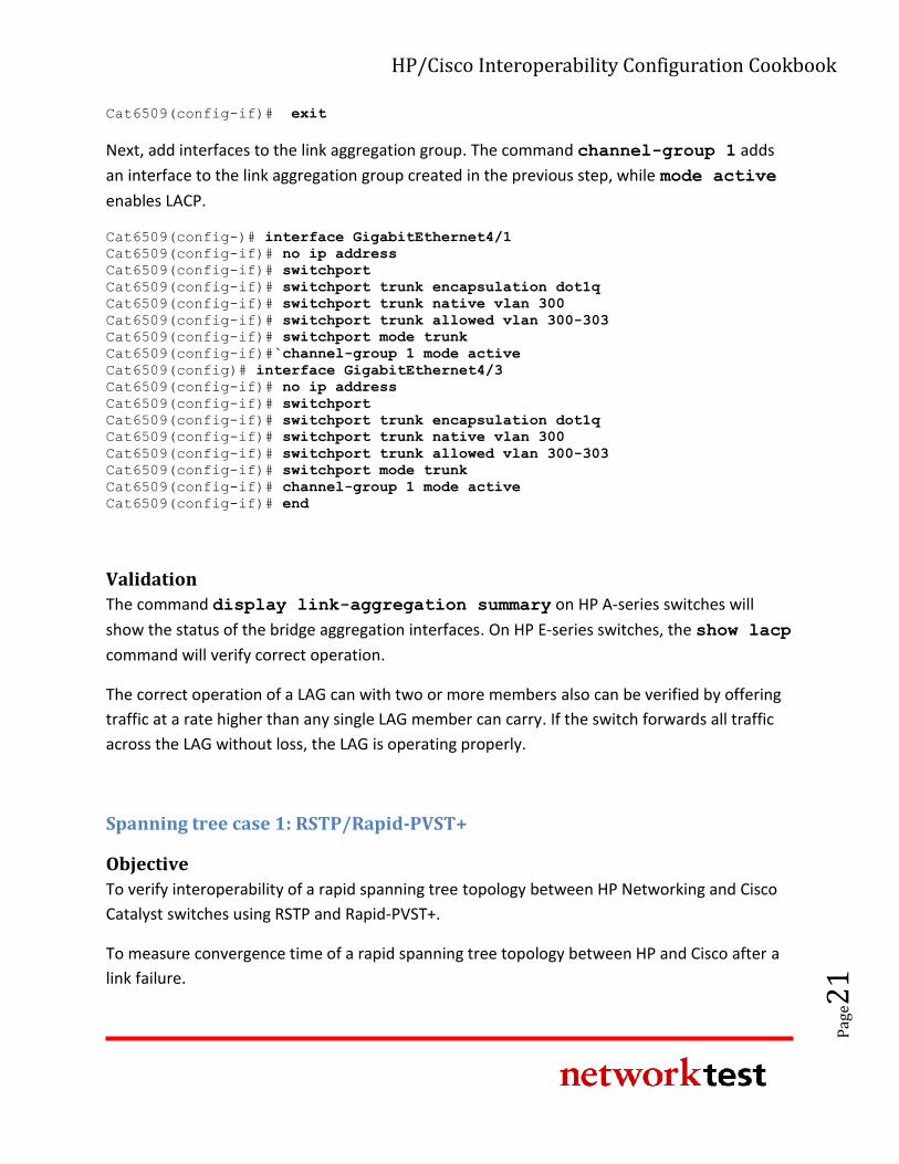
Cat6509(config-if)# exit
Next, add interfaces to the link aggregation group. The command channel-group 1 adds
an interface to the link aggregation group created in the previous step, while mode active
enables LACP.
Cat6509(config-)# interface GigabitEthernet4/1
Cat6509(config-if)# no ip address
Cat6509(config-if)# switchport
Cat6509(config-if)# switchport trunk encapsulation dot1q
Cat6509(config-if)# switchport trunk native vlan 300
Cat6509(config-if)# switchport trunk allowed vlan 300-303
Cat6509(config-if)# switchport mode trunk
Cat6509(config-if)#`channel-group 1 mode active
Cat6509(config)# interface GigabitEthernet4/3
Cat6509(config-if)# no ip address
Cat6509(config-if)# switchport
Cat6509(config-if)# switchport trunk encapsulation dot1q
Cat6509(config-if)# switchport trunk native vlan 300
Cat6509(config-if)# switchport trunk allowed vlan 300-303
Cat6509(config-if)# switchport mode trunk
Cat6509(config-if)# channel-group 1 mode active
Cat6509(config-if)# end
Validation
The command display link-aggregation summary on HP A-series switches will
show the status of the bridge aggregation interfaces. On HP E-series switches, the show lacp
command will verify correct operation.
The correct operation of a LAG can with two or more members also can be verified by offering
traffic at a rate higher than any single LAG member can carry. If the switch forwards all traffic
across the LAG without loss, the LAG is operating properly.
Spanning tree case 1: RSTP/Rapid-PVST+
Objective
To verify interoperability of a rapid spanning tree topology between HP Networking and Cisco
Catalyst switches using RSTP and Rapid-PVST+.
To measure convergence time of a rapid spanning tree topology between HP and Cisco after a
link failure.
HP/Cisco Interoperability Configuration Cookbook
Pag
e22
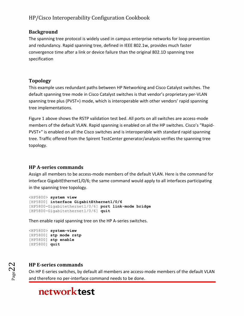
Background
The spanning tree protocol is widely used in campus enterprise networks for loop prevention
and redundancy. Rapid spanning tree, defined in IEEE 802.1w, provides much faster
convergence time after a link or device failure than the original 802.1D spanning tree
specification
Topology
This example uses redundant paths between HP Networking and Cisco Catalyst switches. The
default spanning tree mode in Cisco Catalyst switches is that vendor’s proprietary per-VLAN
spanning tree plus (PVST+) mode, which is interoperable with other vendors’ rapid spanning
tree implementations.
Figure 1 above shows the RSTP validation test bed. All ports on all switches are access-mode
members of the default VLAN. Rapid spanning is enabled on all the HP switches. Cisco’s “Rapid-
PVST+” is enabled on all the Cisco switches and is interoperable with standard rapid spanning
tree. Traffic offered from the Spirent TestCenter generator/analysis verifies the spanning tree
topology.
HP A-series commands
Assign all members to be access-mode members of the default VLAN. Here is the command for
interface GigabitEthernet1/0/6; the same command would apply to all interfaces participating
in the spanning tree topology.
<HP5800> system view
[HP5800] interface GigabitEthernet1/0/6
[HP5800-Gigabitethernet1/0/6] port link-mode bridge
[HP5800-Gigabitethernet1/0/6] quit
Then enable rapid spanning tree on the HP A-series switches.
<HP5800> system-view
[HP5800] stp mode rstp
[HP5800] stp enable
[HP5800] quit
HP E-series commands
On HP E-series switches, by default all members are access-mode members of the default VLAN
and therefore no per-interface command needs to be done.
HP/Cisco Interoperability Configuration Cookbook
Pag
e23
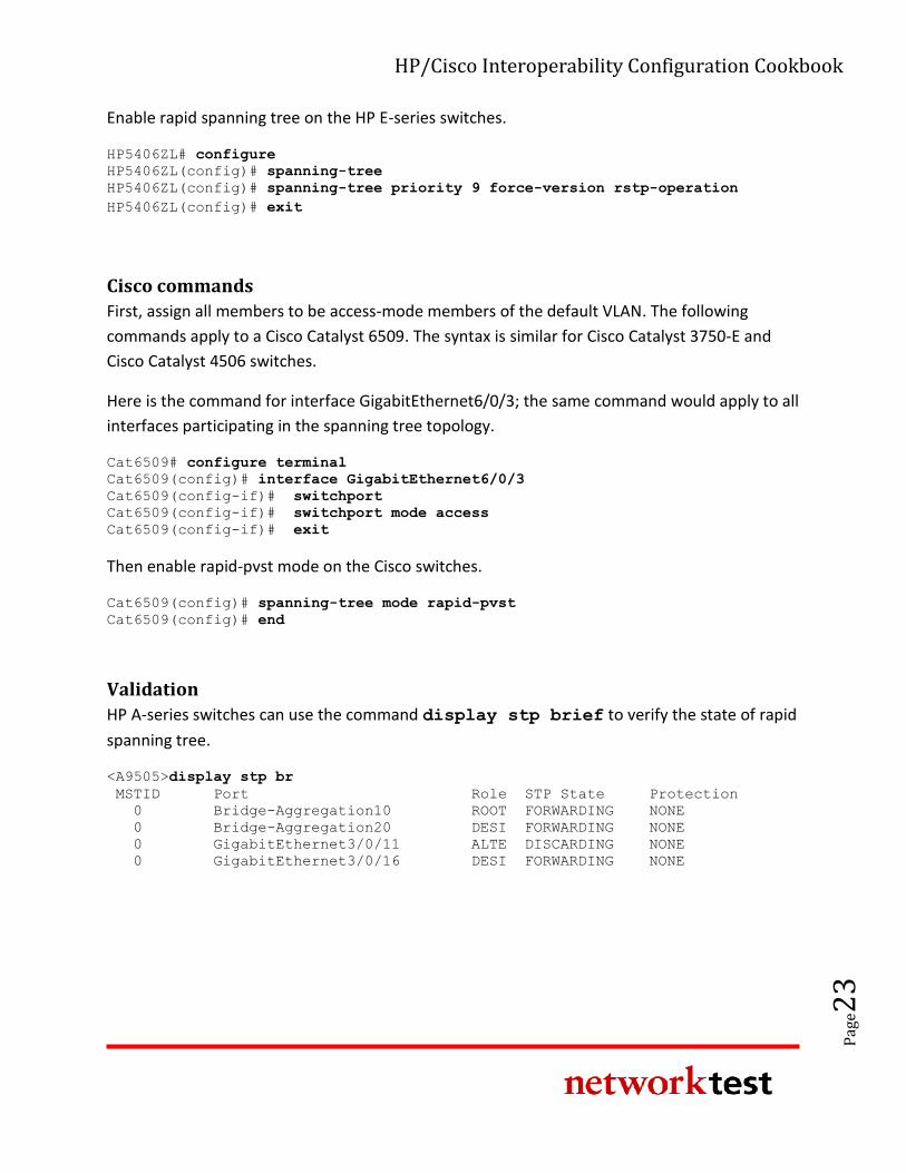
Enable rapid spanning tree on the HP E-series switches.
HP5406ZL# configure
HP5406ZL(config)# spanning-tree
HP5406ZL(config)# spanning-tree priority 9 force-version rstp-operation HP5406ZL(config)# exit
Cisco commands
First, assign all members to be access-mode members of the default VLAN. The following
commands apply to a Cisco Catalyst 6509. The syntax is similar for Cisco Catalyst 3750-E and
Cisco Catalyst 4506 switches.
Here is the command for interface GigabitEthernet6/0/3; the same command would apply to all
interfaces participating in the spanning tree topology.
Cat6509# configure terminal
Cat6509(config)# interface GigabitEthernet6/0/3
Cat6509(config-if)# switchport
Cat6509(config-if)# switchport mode access
Cat6509(config-if)# exit
Then enable rapid-pvst mode on the Cisco switches.
Cat6509(config)# spanning-tree mode rapid-pvst
Cat6509(config)# end
Validation
HP A-series switches can use the command display stp brief to verify the state of rapid
spanning tree.
<A9505>display stp br
MSTID Port Role STP State Protection
0 Bridge-Aggregation10 ROOT FORWARDING NONE
0 Bridge-Aggregation20 DESI FORWARDING NONE
0 GigabitEthernet3/0/11 ALTE DISCARDING NONE
0 GigabitEthernet3/0/16 DESI FORWARDING NONE
HP/Cisco Interoperability Configuration Cookbook
Pag
e24
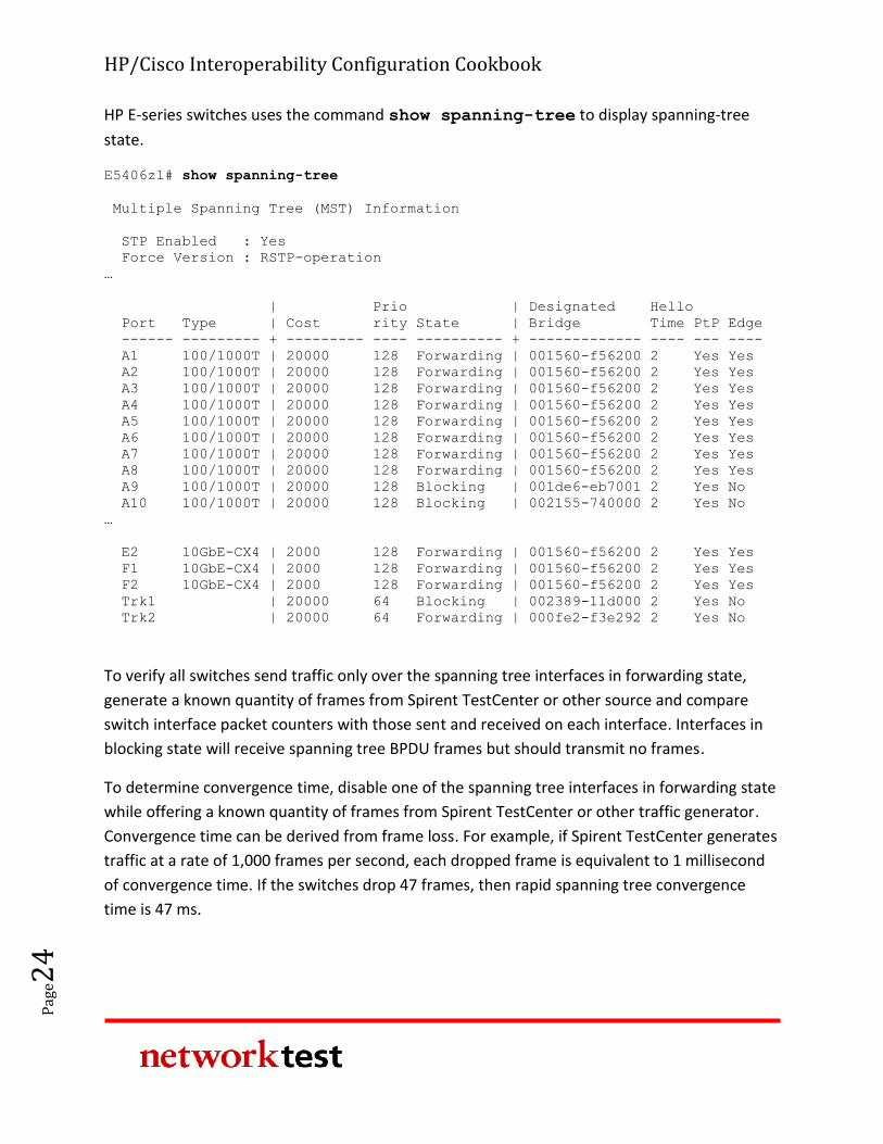
HP E-series switches uses the command show spanning-tree to display spanning-tree
state.
E5406zl# show spanning-tree
Multiple Spanning Tree (MST) Information
STP Enabled : Yes
Force Version : RSTP-operation
…
| Prio | Designated Hello
Port Type | Cost rity State | Bridge Time PtP Edge
------ --------- + --------- ---- ---------- + ------------- ---- --- ----
A1 100/1000T | 20000 128 Forwarding | 001560-f56200 2 Yes Yes
A2 100/1000T | 20000 128 Forwarding | 001560-f56200 2 Yes Yes
A3 100/1000T | 20000 128 Forwarding | 001560-f56200 2 Yes Yes
A4 100/1000T | 20000 128 Forwarding | 001560-f56200 2 Yes Yes
A5 100/1000T | 20000 128 Forwarding | 001560-f56200 2 Yes Yes
A6 100/1000T | 20000 128 Forwarding | 001560-f56200 2 Yes Yes
A7 100/1000T | 20000 128 Forwarding | 001560-f56200 2 Yes Yes
A8 100/1000T | 20000 128 Forwarding | 001560-f56200 2 Yes Yes
A9 100/1000T | 20000 128 Blocking | 001de6-eb7001 2 Yes No
A10 100/1000T | 20000 128 Blocking | 002155-740000 2 Yes No
…
E2 10GbE-CX4 | 2000 128 Forwarding | 001560-f56200 2 Yes Yes
F1 10GbE-CX4 | 2000 128 Forwarding | 001560-f56200 2 Yes Yes
F2 10GbE-CX4 | 2000 128 Forwarding | 001560-f56200 2 Yes Yes
Trk1 | 20000 64 Blocking | 002389-11d000 2 Yes No
Trk2 | 20000 64 Forwarding | 000fe2-f3e292 2 Yes No
To verify all switches send traffic only over the spanning tree interfaces in forwarding state,
generate a known quantity of frames from Spirent TestCenter or other source and compare
switch interface packet counters with those sent and received on each interface. Interfaces in
blocking state will receive spanning tree BPDU frames but should transmit no frames.
To determine convergence time, disable one of the spanning tree interfaces in forwarding state
while offering a known quantity of frames from Spirent TestCenter or other traffic generator.
Convergence time can be derived from frame loss. For example, if Spirent TestCenter generates
traffic at a rate of 1,000 frames per second, each dropped frame is equivalent to 1 millisecond
of convergence time. If the switches drop 47 frames, then rapid spanning tree convergence
time is 47 ms.
HP/Cisco Interoperability Configuration Cookbook
Pag
e25
Spanning tree case 2: MSTP/PVST+
Objective
To verify interoperability of multiple spanning tree protocol (MSTP) and per-vlan spanning tree
protocol plus (PVST+) between HP Networking and Cisco Catalyst switches, respectively.
To measure convergence time of an MSTP-PVST+ topology between HP Networking and Cisco
Catalyst switches after a link failure.
Background
As defined in IEEE specification 802.1s, the multiple spanning tree protocol (MSTP) adds loop
prevention and redundancy on a per-VLAN basis. With MSTP, individual spanning tree
topologies can be configured for each VLAN.
The goal of this exercise is to demonstrate interoperability in a multiple-VLAN environment
when the HP Networking and Cisco Catalyst switches use different variations of spanning tree:
MSTP on HP and PVST+ on a Cisco Catalyst switch.
Topology
This example uses redundant paths between the HP Networking and Cisco Catalyst switches.
VLAN Ids of 300 to 304 have been defined on all switches. MSTP is enabled on all the HP
switches, and Rapid PVST+ is enabled on all the Cisco switches.
Figure 1 above illustrates the MSTP-PVST+ validation test bed. The links interconnecting each
switch are trunk ports that allow tagged traffic from VLAN IDs 300 to 304. Access ports were
configured on the access layer switches, with one port assigned to each VLAN. Traffic offered
from the Spirent TestCenter traffic generator/analyzer verifies the spanning tree topology in
each VLAN.
HP A-series commands
Create VLAN IDs 300 to 304.
<HP5800> system-view
[HP5800] vlan 300 to 304
Configure access-mode ports for their respective VLANs.
HP/Cisco Interoperability Configuration Cookbook
Pag
e26
[HP5800] interface GigabitEthernet1/0/1
[HP5800-Gigabitethernet1/0/1] port link-mode bridge
[HP5800-Gigabitethernet1/0/1] port access vlan 300
[HP5800-Gigabitethernet1/0/1] interface GigabitEthernet1/0/2
[HP5800-Gigabitethernet1/0/2] port link-mode bridge
[HP5800-Gigabitethernet1/0/2] port access vlan 301
[HP5800-Gigabitethernet1/0/2] interface GigabitEthernet1/0/3
[HP5800-Gigabitethernet1/0/3] port link-mode bridge
[HP5800-Gigabitethernet1/0/3] port access vlan 302
[HP5800-Gigabitethernet1/0/3] interface GigabitEthernet1/0/4
[HP5800-Gigabitethernet1/0/4] port link-mode bridge
[HP5800-Gigabitethernet1/0/4] port access vlan 303
[HP5800-Gigabitethernet1/0/4] interface GigabitEthernet1/0/5
[HP5800-Gigabitethernet1/0/5] port link-mode bridge
[HP5800-Gigabitethernet1/0/5] port access vlan 304
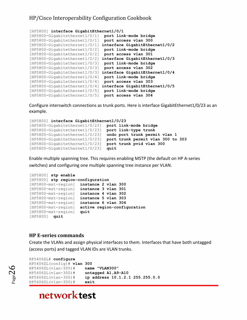
Configure interswitch connections as trunk ports. Here is interface GigabitEthernet1/0/23 as an example.
[HP5800] interface GigabitEthernet1/0/23
[HP5800-Gigabitethernet1/0/23] port link-mode bridge
[HP5800-Gigabitethernet1/0/23] port link-type trunk
[HP5800-Gigabitethernet1/0/23] undo port trunk permit vlan 1
[HP5800-Gigabitethernet1/0/23] port trunk permit vlan 300 to 303
[HP5800-Gigabitethernet1/0/23] port trunk pvid vlan 300
[HP5800-Gigabitethernet1/0/23] quit
Enable multiple spanning tree. This requires enabling MSTP (the default on HP A-series
switches) and configuring one multiple spanning tree instance per VLAN.
[HP5800] stp enable
[HP5800] stp region-configuration
[HP5800-mst-region] instance 2 vlan 300
[HP5800-mst-region] instance 3 vlan 301
[HP5800-mst-region] instance 4 vlan 302
[HP5800-mst-region] instance 5 vlan 303
[HP5800-mst-region] instance 6 vlan 304
[HP5800-mst-region] active region-configuration
[HP5800-mst-region] quit
[HP5800] quit
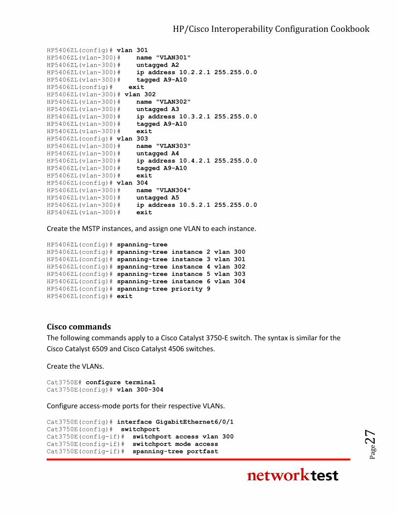
HP E-series commands
Create the VLANs and assign physical interfaces to them. Interfaces that have both untagged
(access ports) and tagged VLAN IDs are VLAN trunks.
HP5406ZL# configure
HP5406ZL(config)# vlan 300
HP5406ZL(vlan-300)# name "VLAN300"
HP5406ZL(vlan-300)# untagged A1,A9-A10
HP5406ZL(vlan-300)# ip address 10.1.2.1 255.255.0.0
HP5406ZL(vlan-300)# exit
HP/Cisco Interoperability Configuration Cookbook
Pag
e27
HP5406ZL(config)# vlan 301
HP5406ZL(vlan-300)# name "VLAN301"
HP5406ZL(vlan-300)# untagged A2
HP5406ZL(vlan-300)# ip address 10.2.2.1 255.255.0.0
HP5406ZL(vlan-300)# tagged A9-A10
HP5406ZL(config)# exit
HP5406ZL(vlan-300)# vlan 302
HP5406ZL(vlan-300)# name "VLAN302"
HP5406ZL(vlan-300)# untagged A3
HP5406ZL(vlan-300)# ip address 10.3.2.1 255.255.0.0
HP5406ZL(vlan-300)# tagged A9-A10
HP5406ZL(vlan-300)# exit
HP5406ZL(config)# vlan 303
HP5406ZL(vlan-300)# name "VLAN303"
HP5406ZL(vlan-300)# untagged A4
HP5406ZL(vlan-300)# ip address 10.4.2.1 255.255.0.0
HP5406ZL(vlan-300)# tagged A9-A10
HP5406ZL(vlan-300)# exit
HP5406ZL(config)# vlan 304
HP5406ZL(vlan-300)# name "VLAN304"
HP5406ZL(vlan-300)# untagged A5
HP5406ZL(vlan-300)# ip address 10.5.2.1 255.255.0.0
HP5406ZL(vlan-300)# exit
Create the MSTP instances, and assign one VLAN to each instance.
HP5406ZL(config)# spanning-tree
HP5406ZL(config)# spanning-tree instance 2 vlan 300
HP5406ZL(config)# spanning-tree instance 3 vlan 301
HP5406ZL(config)# spanning-tree instance 4 vlan 302
HP5406ZL(config)# spanning-tree instance 5 vlan 303
HP5406ZL(config)# spanning-tree instance 6 vlan 304
HP5406ZL(config)# spanning-tree priority 9
HP5406ZL(config)# exit
Cisco commands
The following commands apply to a Cisco Catalyst 3750-E switch. The syntax is similar for the
Cisco Catalyst 6509 and Cisco Catalyst 4506 switches.
Create the VLANs.
Cat3750E# configure terminal
Cat3750E(config)# vlan 300-304
Configure access-mode ports for their respective VLANs.
Cat3750E(config)# interface GigabitEthernet6/0/1
Cat3750E(config)# switchport
Cat3750E(config-if)# switchport access vlan 300
Cat3750E(config-if)# switchport mode access
Cat3750E(config-if)# spanning-tree portfast
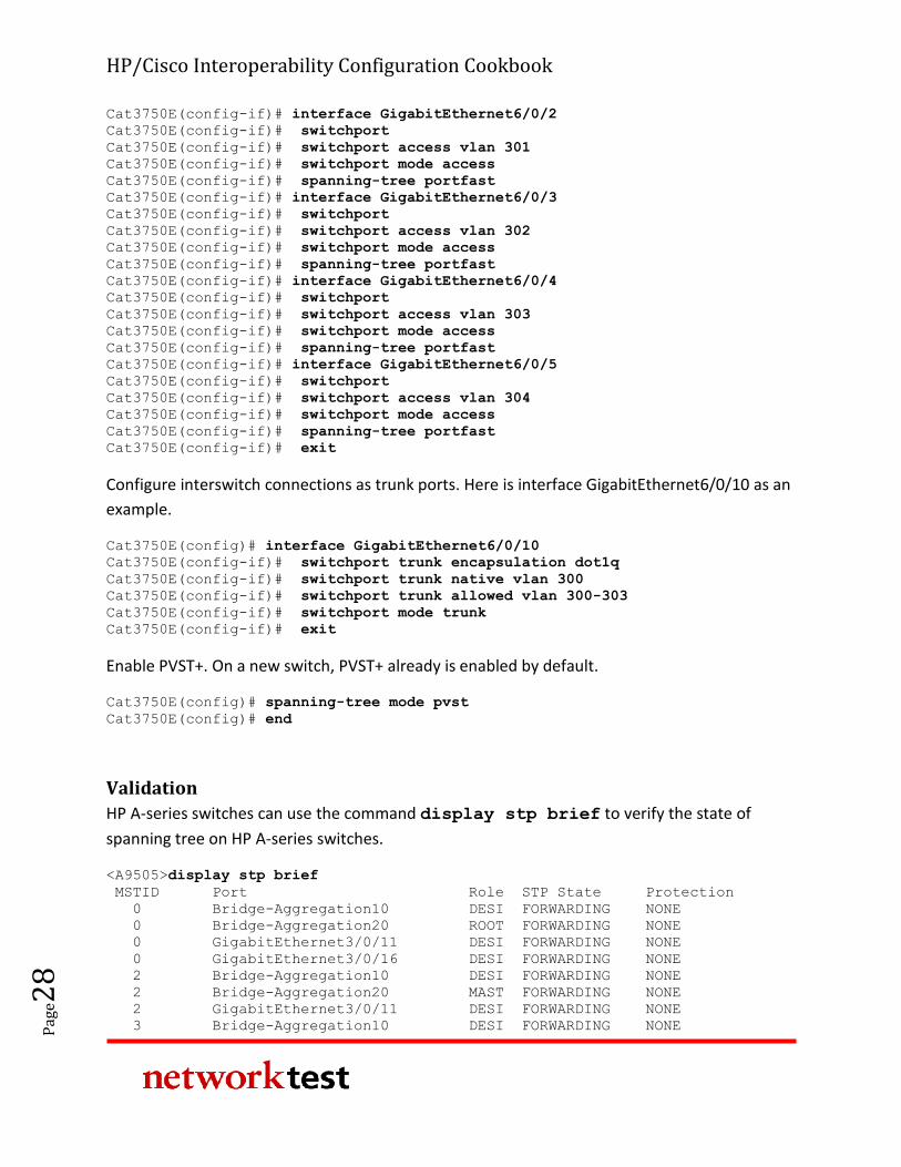
HP/Cisco Interoperability Configuration Cookbook
Pag
e28
Cat3750E(config-if)# interface GigabitEthernet6/0/2
Cat3750E(config-if)# switchport
Cat3750E(config-if)# switchport access vlan 301
Cat3750E(config-if)# switchport mode access
Cat3750E(config-if)# spanning-tree portfast
Cat3750E(config-if)# interface GigabitEthernet6/0/3
Cat3750E(config-if)# switchport
Cat3750E(config-if)# switchport access vlan 302
Cat3750E(config-if)# switchport mode access
Cat3750E(config-if)# spanning-tree portfast
Cat3750E(config-if)# interface GigabitEthernet6/0/4
Cat3750E(config-if)# switchport
Cat3750E(config-if)# switchport access vlan 303
Cat3750E(config-if)# switchport mode access
Cat3750E(config-if)# spanning-tree portfast
Cat3750E(config-if)# interface GigabitEthernet6/0/5
Cat3750E(config-if)# switchport
Cat3750E(config-if)# switchport access vlan 304
Cat3750E(config-if)# switchport mode access
Cat3750E(config-if)# spanning-tree portfast
Cat3750E(config-if)# exit
Configure interswitch connections as trunk ports. Here is interface GigabitEthernet6/0/10 as an
example.
Cat3750E(config)# interface GigabitEthernet6/0/10
Cat3750E(config-if)# switchport trunk encapsulation dot1q
Cat3750E(config-if)# switchport trunk native vlan 300
Cat3750E(config-if)# switchport trunk allowed vlan 300-303
Cat3750E(config-if)# switchport mode trunk
Cat3750E(config-if)# exit
Enable PVST+. On a new switch, PVST+ already is enabled by default.
Cat3750E(config)# spanning-tree mode pvst
Cat3750E(config)# end
Validation
HP A-series switches can use the command display stp brief to verify the state of
spanning tree on HP A-series switches.
<A9505>display stp brief
MSTID Port Role STP State Protection
0 Bridge-Aggregation10 DESI FORWARDING NONE
0 Bridge-Aggregation20 ROOT FORWARDING NONE
0 GigabitEthernet3/0/11 DESI FORWARDING NONE
0 GigabitEthernet3/0/16 DESI FORWARDING NONE
2 Bridge-Aggregation10 DESI FORWARDING NONE
2 Bridge-Aggregation20 MAST FORWARDING NONE
2 GigabitEthernet3/0/11 DESI FORWARDING NONE
3 Bridge-Aggregation10 DESI FORWARDING NONE
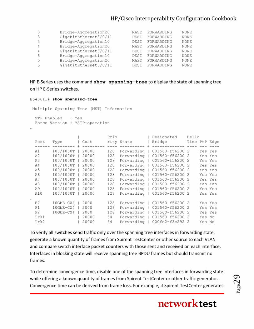
HP/Cisco Interoperability Configuration Cookbook
Pag
e29
3 Bridge-Aggregation20 MAST FORWARDING NONE
3 GigabitEthernet3/0/11 DESI FORWARDING NONE
4 Bridge-Aggregation10 DESI FORWARDING NONE
4 Bridge-Aggregation20 MAST FORWARDING NONE
4 GigabitEthernet3/0/11 DESI FORWARDING NONE
5 Bridge-Aggregation10 DESI FORWARDING NONE
5 Bridge-Aggregation20 MAST FORWARDING NONE
5 GigabitEthernet3/0/11 DESI FORWARDING NONE
HP E-Series uses the command show spanning-tree to display the state of spanning tree
on HP E-Series switches.
E5406zl# show spanning-tree
Multiple Spanning Tree (MST) Information
STP Enabled : Yes
Force Version : MSTP-operation
…
| Prio | Designated Hello
Port Type | Cost rity State | Bridge Time PtP Edge
------ --------- + --------- ---- ---------- + ------------- ---- --- ----
A1 100/1000T | 20000 128 Forwarding | 001560-f56200 2 Yes Yes
A2 100/1000T | 20000 128 Forwarding | 001560-f56200 2 Yes Yes
A3 100/1000T | 20000 128 Forwarding | 001560-f56200 2 Yes Yes
A4 100/1000T | 20000 128 Forwarding | 001560-f56200 2 Yes Yes
A5 100/1000T | 20000 128 Forwarding | 001560-f56200 2 Yes Yes
A6 100/1000T | 20000 128 Forwarding | 001560-f56200 2 Yes Yes
A7 100/1000T | 20000 128 Forwarding | 001560-f56200 2 Yes Yes
A8 100/1000T | 20000 128 Forwarding | 001560-f56200 2 Yes Yes
A9 100/1000T | 20000 128 Forwarding | 001560-f56200 2 Yes Yes
A10 100/1000T | 20000 128 Forwarding | 001560-f56200 2 Yes Yes
…
E2 10GbE-CX4 | 2000 128 Forwarding | 001560-f56200 2 Yes Yes
F1 10GbE-CX4 | 2000 128 Forwarding | 001560-f56200 2 Yes Yes
F2 10GbE-CX4 | 2000 128 Forwarding | 001560-f56200 2 Yes Yes
Trk1 | 20000 64 Forwarding | 001560-f56200 2 Yes No
Trk2 | 20000 64 Forwarding | 000fe2-f3e292 2 Yes No
To verify all switches send traffic only over the spanning tree interfaces in forwarding state,
generate a known quantity of frames from Spirent TestCenter or other source to each VLAN
and compare switch interface packet counters with those sent and received on each interface.
Interfaces in blocking state will receive spanning tree BPDU frames but should transmit no
frames.
To determine convergence time, disable one of the spanning tree interfaces in forwarding state
while offering a known quantity of frames from Spirent TestCenter or other traffic generator.
Convergence time can be derived from frame loss. For example, if Spirent TestCenter generates
HP/Cisco Interoperability Configuration Cookbook
Pag
e30
traffic at a rate of 1,000 frames per second, each dropped frame is equivalent to 1 millisecond
of convergence time. If the switches drop 47 frames, then spanning tree convergence time is 47
ms.
Spanning tree case 3: MSTP/Rapid-PVST+
Objective
To verify interoperability of multiple spanning tree protocol (MSTP) and rapid per-VLAN
spanning tree protocol plus (Rapid PVST+) between HP Networking and Cisco Catalyst switches,
respectively.
To measure convergence time of an MSTP-Rapid PVST+ topology between HP Networking and
Cisco Catalyst switches after a link failure.
Background
As defined in IEEE specification 802.1s, the multiple spanning tree protocol (MSTP) adds loop
prevention and redundancy on a per-VLAN basis. With MSTP, individual spanning tree
topologies can be configured for each VLAN.
The goal of this exercise is to demonstrate interoperability in a multiple-VLAN environment
when the HP Networking and Cisco Catalyst switches use different variations of spanning tree:
MSTP on HP switches and Rapid PVST+ on Cisco Catalyst switches.
Topology
This example uses redundant paths between the HP Networking and Cisco Catalyst switches.
VLAN Ids of 300 to 304 have been defined on all switches. MSTP is enabled on all HP switches,
with Rapid PVST+ defined on all Cisco switches.
Figure 1 above illustrates the MSTP-Rapid PVST+ validation test bed. The links interconnecting
each switch are trunk ports that allow tagged traffic from the VLAN IDs 300 to 304. Access ports
were configured on the access layer switches, with one port per vlan being configured. Traffic
offered from the Spirent TestCenter traffic generator/analyzer verifies the spanning tree
topology in each VLAN.
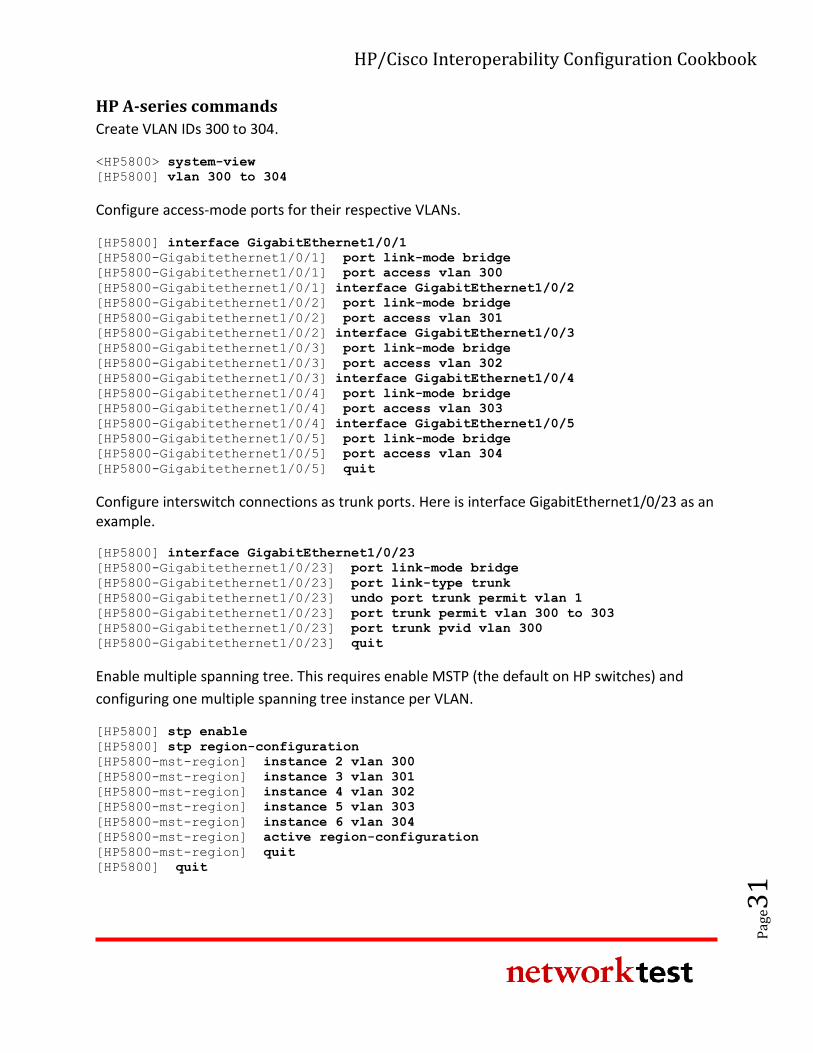
HP/Cisco Interoperability Configuration Cookbook
Pag
e31
HP A-series commands
Create VLAN IDs 300 to 304.
<HP5800> system-view
[HP5800] vlan 300 to 304
Configure access-mode ports for their respective VLANs.
[HP5800] interface GigabitEthernet1/0/1
[HP5800-Gigabitethernet1/0/1] port link-mode bridge
[HP5800-Gigabitethernet1/0/1] port access vlan 300
[HP5800-Gigabitethernet1/0/1] interface GigabitEthernet1/0/2
[HP5800-Gigabitethernet1/0/2] port link-mode bridge
[HP5800-Gigabitethernet1/0/2] port access vlan 301
[HP5800-Gigabitethernet1/0/2] interface GigabitEthernet1/0/3
[HP5800-Gigabitethernet1/0/3] port link-mode bridge
[HP5800-Gigabitethernet1/0/3] port access vlan 302
[HP5800-Gigabitethernet1/0/3] interface GigabitEthernet1/0/4
[HP5800-Gigabitethernet1/0/4] port link-mode bridge
[HP5800-Gigabitethernet1/0/4] port access vlan 303
[HP5800-Gigabitethernet1/0/4] interface GigabitEthernet1/0/5
[HP5800-Gigabitethernet1/0/5] port link-mode bridge
[HP5800-Gigabitethernet1/0/5] port access vlan 304
[HP5800-Gigabitethernet1/0/5] quit
Configure interswitch connections as trunk ports. Here is interface GigabitEthernet1/0/23 as an example.
[HP5800] interface GigabitEthernet1/0/23
[HP5800-Gigabitethernet1/0/23] port link-mode bridge
[HP5800-Gigabitethernet1/0/23] port link-type trunk
[HP5800-Gigabitethernet1/0/23] undo port trunk permit vlan 1
[HP5800-Gigabitethernet1/0/23] port trunk permit vlan 300 to 303
[HP5800-Gigabitethernet1/0/23] port trunk pvid vlan 300
[HP5800-Gigabitethernet1/0/23] quit
Enable multiple spanning tree. This requires enable MSTP (the default on HP switches) and
configuring one multiple spanning tree instance per VLAN.
[HP5800] stp enable
[HP5800] stp region-configuration
[HP5800-mst-region] instance 2 vlan 300
[HP5800-mst-region] instance 3 vlan 301
[HP5800-mst-region] instance 4 vlan 302
[HP5800-mst-region] instance 5 vlan 303
[HP5800-mst-region] instance 6 vlan 304
[HP5800-mst-region] active region-configuration
[HP5800-mst-region] quit
[HP5800] quit
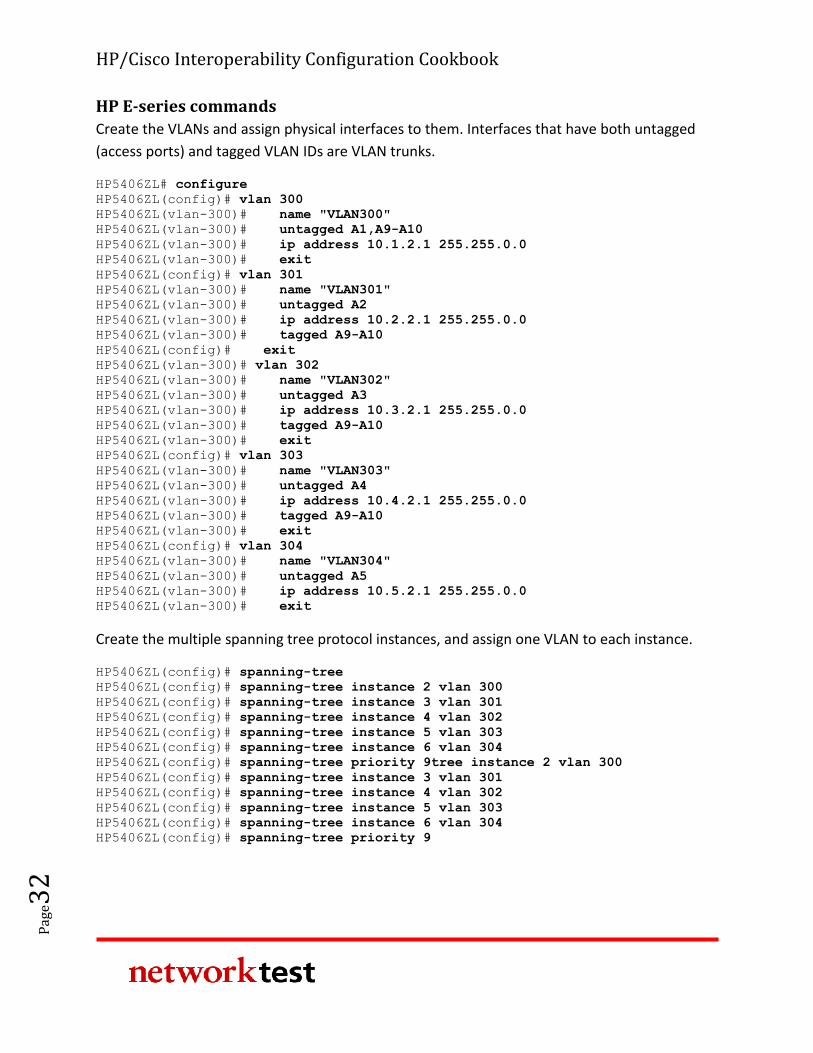
HP/Cisco Interoperability Configuration Cookbook
Pag
e32
HP E-series commands
Create the VLANs and assign physical interfaces to them. Interfaces that have both untagged
(access ports) and tagged VLAN IDs are VLAN trunks.
HP5406ZL# configure
HP5406ZL(config)# vlan 300
HP5406ZL(vlan-300)# name "VLAN300"
HP5406ZL(vlan-300)# untagged A1,A9-A10
HP5406ZL(vlan-300)# ip address 10.1.2.1 255.255.0.0
HP5406ZL(vlan-300)# exit
HP5406ZL(config)# vlan 301
HP5406ZL(vlan-300)# name "VLAN301"
HP5406ZL(vlan-300)# untagged A2
HP5406ZL(vlan-300)# ip address 10.2.2.1 255.255.0.0
HP5406ZL(vlan-300)# tagged A9-A10
HP5406ZL(config)# exit
HP5406ZL(vlan-300)# vlan 302
HP5406ZL(vlan-300)# name "VLAN302"
HP5406ZL(vlan-300)# untagged A3
HP5406ZL(vlan-300)# ip address 10.3.2.1 255.255.0.0
HP5406ZL(vlan-300)# tagged A9-A10
HP5406ZL(vlan-300)# exit
HP5406ZL(config)# vlan 303
HP5406ZL(vlan-300)# name "VLAN303"
HP5406ZL(vlan-300)# untagged A4
HP5406ZL(vlan-300)# ip address 10.4.2.1 255.255.0.0
HP5406ZL(vlan-300)# tagged A9-A10
HP5406ZL(vlan-300)# exit
HP5406ZL(config)# vlan 304
HP5406ZL(vlan-300)# name "VLAN304"
HP5406ZL(vlan-300)# untagged A5
HP5406ZL(vlan-300)# ip address 10.5.2.1 255.255.0.0
HP5406ZL(vlan-300)# exit
Create the multiple spanning tree protocol instances, and assign one VLAN to each instance.
HP5406ZL(config)# spanning-tree
HP5406ZL(config)# spanning-tree instance 2 vlan 300
HP5406ZL(config)# spanning-tree instance 3 vlan 301
HP5406ZL(config)# spanning-tree instance 4 vlan 302
HP5406ZL(config)# spanning-tree instance 5 vlan 303
HP5406ZL(config)# spanning-tree instance 6 vlan 304
HP5406ZL(config)# spanning-tree priority 9tree instance 2 vlan 300
HP5406ZL(config)# spanning-tree instance 3 vlan 301
HP5406ZL(config)# spanning-tree instance 4 vlan 302
HP5406ZL(config)# spanning-tree instance 5 vlan 303
HP5406ZL(config)# spanning-tree instance 6 vlan 304
HP5406ZL(config)# spanning-tree priority 9
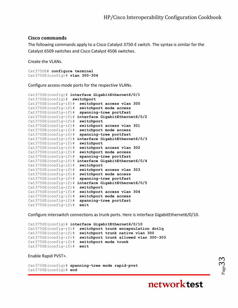
HP/Cisco Interoperability Configuration Cookbook
Pag
e33
Cisco commands
The following commands apply to a Cisco Catalyst 3750-E switch. The syntax is similar for the
Catalyst 6509 switches and Cisco Catalyst 4506 switches.
Create the VLANs.
Cat3750E# configure terminal
Cat3750E(config)# vlan 300-304
Configure access-mode ports for the respective VLANs.
Cat3750E(config)# interface GigabitEthernet6/0/1
Cat3750E(config)# switchport
Cat3750E(config-if)# switchport access vlan 300
Cat3750E(config-if)# switchport mode access
Cat3750E(config-if)# spanning-tree portfast
Cat3750E(config-if)# interface GigabitEthernet6/0/2
Cat3750E(config-if)# switchport
Cat3750E(config-if)# switchport access vlan 301
Cat3750E(config-if)# switchport mode access
Cat3750E(config-if)# spanning-tree portfast
Cat3750E(config-if)# interface GigabitEthernet6/0/3
Cat3750E(config-if)# switchport
Cat3750E(config-if)# switchport access vlan 302
Cat3750E(config-if)# switchport mode access
Cat3750E(config-if)# spanning-tree portfast
Cat3750E(config-if)# interface GigabitEthernet6/0/4
Cat3750E(config-if)# switchport
Cat3750E(config-if)# switchport access vlan 303
Cat3750E(config-if)# switchport mode access
Cat3750E(config-if)# spanning-tree portfast
Cat3750E(config-if)# interface GigabitEthernet6/0/5
Cat3750E(config-if)# switchport
Cat3750E(config-if)# switchport access vlan 304
Cat3750E(config-if)# switchport mode access
Cat3750E(config-if)# spanning-tree portfast
Cat3750E(config-if)# exit
Configure interswitch connections as trunk ports. Here is interface GigabitEthernet6/0/10.
Cat3750E(config)# interface GigabitEthernet6/0/10
Cat3750E(config-if)# switchport trunk encapsulation dot1q
Cat3750E(config-if)# switchport trunk native vlan 300
Cat3750E(config-if)# switchport trunk allowed vlan 300-303
Cat3750E(config-if)# switchport mode trunk
Cat3750E(config-if)# exit
Enable Rapid PVST+.
Cat3750E(config)# spanning-tree mode rapid-pvst
Cat3750E(config)# end
HP/Cisco Interoperability Configuration Cookbook
Pag
e34
Validation
HP A-series switches can use the command display stp brief to verify the state of
spanning tree on HP A-series switches. HP E-series uses the command show spanning-
tree to display the state of spanning tree on HP E-series switches.
To verify switches send traffic only over the spanning tree interfaces in forwarding state,
generate a known quantity of frames from Spirent TestCenter to each VLAN and compare
switch interface packet counters with those sent and received on each interface. Interfaces in
blocking state will receive spanning tree BPDU frames but should transmit no frames.
To determine convergence time, disable one of the spanning tree interfaces in forwarding state
while offering a known quantity of frames from Spirent TestCenter or other traffic generator.
Convergence time can be derived from frame loss. For example, if Spirent TestCenter generates
traffic at a rate of 1,000 frames per second, each dropped frame is equivalent to 1 millisecond
of convergence time. If the switches drop 47 frames, then spanning tree convergence time is 47
ms.
Spanning tree case 4: MSTP/MSTP
Objective
To verify interoperability of a multiple spanning tree topology between HP Networking and
Cisco Catalyst switches.
To measure convergence time of a multiple spanning tree topology between HP and Cisco
switches after a link failure.
Background
As defined in IEEE specification 802.1s, the multiple spanning tree protocol (MSTP) adds loop
prevention and redundancy on a per-VLAN basis. With MSTP, a separate spanning tree topology
can be configured for each VLAN.
MSTP is the default spanning tree protocol for HP Networking switches. MSTP is enabled by
default on HP A-series switches, and disabled by default on HP E-series switches.
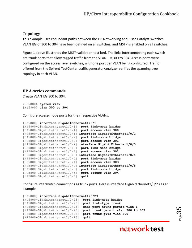
HP/Cisco Interoperability Configuration Cookbook
Pag
e35
Topology
This example uses redundant paths between the HP Networking and Cisco Catalyst switches.
VLAN IDs of 300 to 304 have been defined on all switches, and MSTP is enabled on all switches.
Figure 1 above illustrates the MSTP validation test bed. The links interconnecting each switch
are trunk ports that allow tagged traffic from the VLAN IDs 300 to 304. Access ports were
configured on the access layer switches, with one port per VLAN being configured. Traffic
offered from the Spirent TestCenter traffic generator/analyzer verifies the spanning tree
topology in each VLAN.
HP A-series commands
Create VLAN IDs 300 to 304.
<HP5800> system-view
[HP5800] vlan 300 to 304
Configure access-mode ports for their respective VLANs.
[HP5800] interface GigabitEthernet1/0/1
[HP5800-Gigabitethernet1/0/1] port link-mode bridge
[HP5800-Gigabitethernet1/0/1] port access vlan 300
[HP5800-Gigabitethernet1/0/1] interface GigabitEthernet1/0/2
[HP5800-Gigabitethernet1/0/2] port link-mode bridge
[HP5800-Gigabitethernet1/0/2] port access vlan 301
[HP5800-Gigabitethernet1/0/2] interface GigabitEthernet1/0/3
[HP5800-Gigabitethernet1/0/3] port link-mode bridge
[HP5800-Gigabitethernet1/0/3] port access vlan 302
[HP5800-Gigabitethernet1/0/3] interface GigabitEthernet1/0/4
[HP5800-Gigabitethernet1/0/4] port link-mode bridge
[HP5800-Gigabitethernet1/0/4] port access vlan 303
[HP5800-Gigabitethernet1/0/4] interface GigabitEthernet1/0/5
[HP5800-Gigabitethernet1/0/5] port link-mode bridge
[HP5800-Gigabitethernet1/0/5] port access vlan 304
[HP5800-Gigabitethernet1/0/5] quit
Configure interswitch connections as trunk ports. Here is interface GigabitEthernet1/0/23 as an example.
[HP5800] interface GigabitEthernet1/0/23
[HP5800-Gigabitethernet1/0/23] port link-mode bridge
[HP5800-Gigabitethernet1/0/23] port link-type trunk
[HP5800-Gigabitethernet1/0/23] undo port trunk permit vlan 1
[HP5800-Gigabitethernet1/0/23] port trunk permit vlan 300 to 303
[HP5800-Gigabitethernet1/0/23] port trunk pvid vlan 300
[HP5800-Gigabitethernet1/0/23] quit
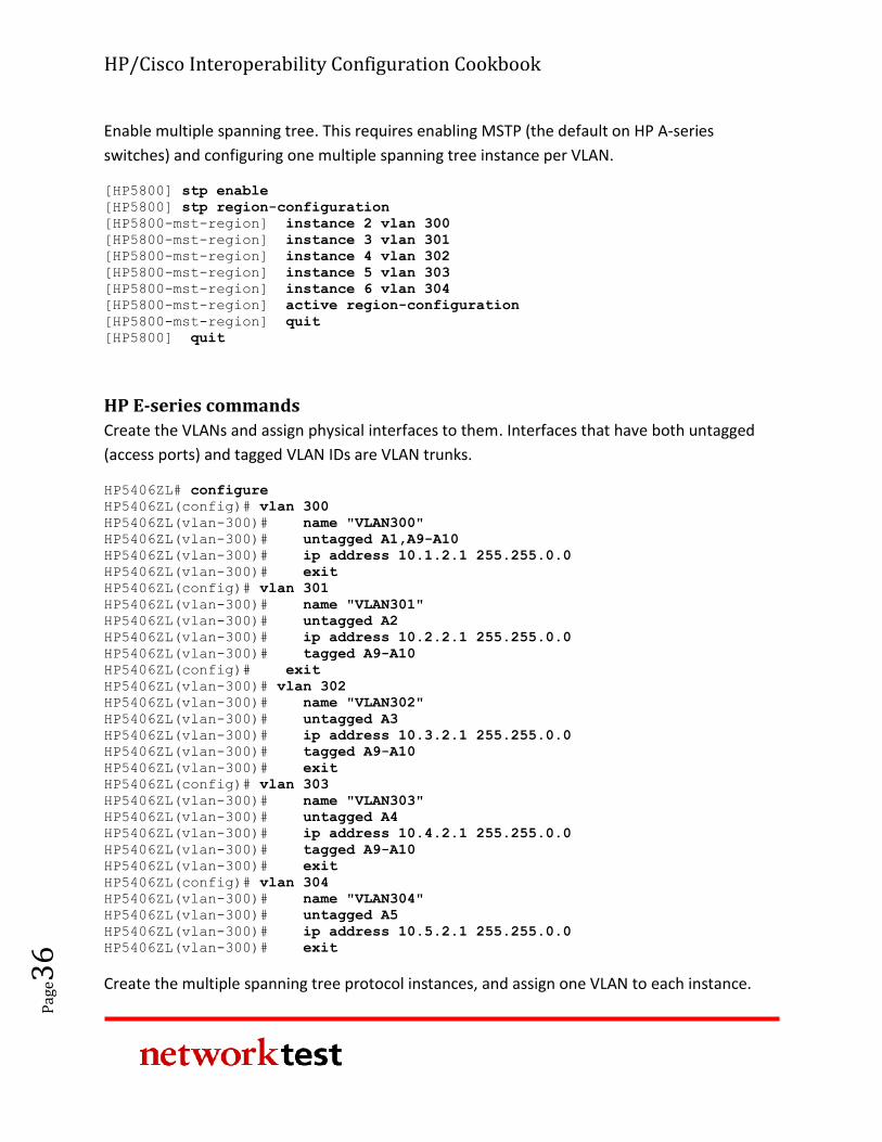
HP/Cisco Interoperability Configuration Cookbook
Pag
e36
Enable multiple spanning tree. This requires enabling MSTP (the default on HP A-series
switches) and configuring one multiple spanning tree instance per VLAN.
[HP5800] stp enable
[HP5800] stp region-configuration
[HP5800-mst-region] instance 2 vlan 300
[HP5800-mst-region] instance 3 vlan 301
[HP5800-mst-region] instance 4 vlan 302
[HP5800-mst-region] instance 5 vlan 303
[HP5800-mst-region] instance 6 vlan 304
[HP5800-mst-region] active region-configuration
[HP5800-mst-region] quit
[HP5800] quit
HP E-series commands
Create the VLANs and assign physical interfaces to them. Interfaces that have both untagged
(access ports) and tagged VLAN IDs are VLAN trunks.
HP5406ZL# configure
HP5406ZL(config)# vlan 300
HP5406ZL(vlan-300)# name "VLAN300"
HP5406ZL(vlan-300)# untagged A1,A9-A10
HP5406ZL(vlan-300)# ip address 10.1.2.1 255.255.0.0
HP5406ZL(vlan-300)# exit
HP5406ZL(config)# vlan 301
HP5406ZL(vlan-300)# name "VLAN301"
HP5406ZL(vlan-300)# untagged A2
HP5406ZL(vlan-300)# ip address 10.2.2.1 255.255.0.0
HP5406ZL(vlan-300)# tagged A9-A10
HP5406ZL(config)# exit
HP5406ZL(vlan-300)# vlan 302
HP5406ZL(vlan-300)# name "VLAN302"
HP5406ZL(vlan-300)# untagged A3
HP5406ZL(vlan-300)# ip address 10.3.2.1 255.255.0.0
HP5406ZL(vlan-300)# tagged A9-A10
HP5406ZL(vlan-300)# exit
HP5406ZL(config)# vlan 303
HP5406ZL(vlan-300)# name "VLAN303"
HP5406ZL(vlan-300)# untagged A4
HP5406ZL(vlan-300)# ip address 10.4.2.1 255.255.0.0
HP5406ZL(vlan-300)# tagged A9-A10
HP5406ZL(vlan-300)# exit
HP5406ZL(config)# vlan 304
HP5406ZL(vlan-300)# name "VLAN304"
HP5406ZL(vlan-300)# untagged A5
HP5406ZL(vlan-300)# ip address 10.5.2.1 255.255.0.0
HP5406ZL(vlan-300)# exit
Create the multiple spanning tree protocol instances, and assign one VLAN to each instance.
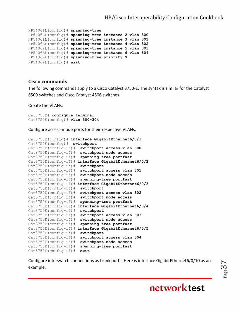
HP/Cisco Interoperability Configuration Cookbook
Pag
e37
HP5406ZL(config)# spanning-tree
HP5406ZL(config)# spanning-tree instance 2 vlan 300
HP5406ZL(config)# spanning-tree instance 3 vlan 301
HP5406ZL(config)# spanning-tree instance 4 vlan 302
HP5406ZL(config)# spanning-tree instance 5 vlan 303
HP5406ZL(config)# spanning-tree instance 6 vlan 304
HP5406ZL(config)# spanning-tree priority 9 HP5406ZL(config)# exit
Cisco commands
The following commands apply to a Cisco Catalyst 3750-E. The syntax is similar for the Catalyst
6509 switches and Cisco Catalyst 4506 switches.
Create the VLANs.
Cat3750E# configure terminal
Cat3750E(config)# vlan 300-304
Configure access-mode ports for their respective VLANs.
Cat3750E(config)# interface GigabitEthernet6/0/1
Cat3750E(config)# switchport
Cat3750E(config-if)# switchport access vlan 300
Cat3750E(config-if)# switchport mode access
Cat3750E(config-if)# spanning-tree portfast
Cat3750E(config-if)# interface GigabitEthernet6/0/2
Cat3750E(config-if)# switchport
Cat3750E(config-if)# switchport access vlan 301
Cat3750E(config-if)# switchport mode access
Cat3750E(config-if)# spanning-tree portfast
Cat3750E(config-if)# interface GigabitEthernet6/0/3
Cat3750E(config-if)# switchport
Cat3750E(config-if)# switchport access vlan 302
Cat3750E(config-if)# switchport mode access
Cat3750E(config-if)# spanning-tree portfast
Cat3750E(config-if)# interface GigabitEthernet6/0/4
Cat3750E(config-if)# switchport
Cat3750E(config-if)# switchport access vlan 303
Cat3750E(config-if)# switchport mode access
Cat3750E(config-if)# spanning-tree portfast
Cat3750E(config-if)# interface GigabitEthernet6/0/5
Cat3750E(config-if)# switchport
Cat3750E(config-if)# switchport access vlan 304
Cat3750E(config-if)# switchport mode access
Cat3750E(config-if)# spanning-tree portfast
Cat3750E(config-if)# exit
Configure interswitch connections as trunk ports. Here is interface GigabitEthernet6/0/10 as an
example.
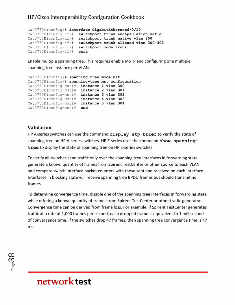
HP/Cisco Interoperability Configuration Cookbook
Pag
e38
Cat3750E(config)# interface GigabitEthernet6/0/10
Cat3750E(config-if)# switchport trunk encapsulation dot1q
Cat3750E(config-if)# switchport trunk native vlan 300
Cat3750E(config-if)# switchport trunk allowed vlan 300-303
Cat3750E(config-if)# switchport mode trunk
Cat3750E(config-if)# exit
Enable multiple spanning tree. This requires enable MSTP and configuring one multiple
spanning tree instance per VLAN.
Cat3750E(config)# spanning-tree mode mst
Cat3750E(config)# spanning-tree mst configuration
Cat3750E(config-mst)# instance 1 vlan 300
Cat3750E(config-mst)# instance 2 vlan 301
Cat3750E(config-mst)# instance 3 vlan 302
Cat3750E(config-mst)# instance 4 vlan 303
Cat3750E(config-mst)# instance 5 vlan 304
Cat3750E(config-mst)# end
Validation
HP A-series switches can use the command display stp brief to verify the state of
spanning tree on HP A-series switches. HP E-series uses the command show spanning-
tree to display the state of spanning tree on HP E-series switches.
To verify all switches send traffic only over the spanning tree interfaces in forwarding state,
generate a known quantity of frames from Spirent TestCenter or other source to each VLAN
and compare switch interface packet counters with those sent and received on each interface.
Interfaces in blocking state will receive spanning tree BPDU frames but should transmit no
frames.
To determine convergence time, disable one of the spanning tree interfaces in forwarding state
while offering a known quantity of frames from Spirent TestCenter or other traffic generator.
Convergence time can be derived from frame loss. For example, if Spirent TestCenter generates
traffic at a rate of 1,000 frames per second, each dropped frame is equivalent to 1 millisecond
of convergence time. If the switches drop 47 frames, then spanning tree convergence time is 47
ms.
HP/Cisco Interoperability Configuration Cookbook
Pag
e39
OSPFv2 (OSPF for IPv4)
Objective
To verify that HP Networking and Cisco Catalyst switches are able to establish open shortest
path first version 2 (OSPFv2) connections and exchange topology information.
Background
Intended for use on IPv4 networks, OSPFv2 supports IP subnetting and redistribution of routing
information learned via other protocols. OSPF also allows session authentication and uses IP
multicast for distribution of routing updates.
OSPF uses areas to segment traffic, with area 0 designated as the backbone network. OSPF
typically involves coordination among multiple internal routers; area border routers (ABRs)
connected to multiple areas; and autonomous system boundary routers (ASBRs).
In addition to standard areas, OSPFv2 also defines two special types of areas: Stubs are areas
into which information on external routes is not sent. Instead, the area border router (ABR)
generates a default external route into the stub area. A Not-So-Stubby-Area (NSSA) is like a stub
area, but it can import external routes into the area for redistribution via OSPF.
Topology
This example uses multiple paths between HP and Cisco devices. Each HP and Cisco switch was
configured with multiple networks, which were then advertised by OSPF to its neighbors.
Figure 1 above illustrates the OSPFv2 test bed. Access switches were connected to both
distribution switches and the distribution switches were connected to both core switches.
Traffic offered from the Spirent TestCenter traffic generator/analyzer verifies that traffic is
indeed being passed between networks.
HP A-series commands
In this example, switched virtual interfaces (SVIs) are created using VLAN interfaces. Physical
interfaces are then mapped to the VLAN interfaces. Routing is done between VLAN interfaces
on each switch.
Create the VLANs.
HP/Cisco Interoperability Configuration Cookbook
Pag
e40
<HP5800> system-view
[HP5800] vlan 1
[HP5800] vlan 2 to 9
Create the switched virtual interfaces.
[HP5800] interface Vlan-interface2
[HP5800-vlan-interface2] ip address 10.0.2.1 255.255.255.0
[HP5800-vlan-interface2] interface Vlan-interface3
[HP5800-vlan-interface3] ip address 10.0.3.1 255.255.255.0
[HP5800-vlan-interface3] interface Vlan-interface4
[HP5800-vlan-interface4] ip address 10.0.4.1 255.255.255.0
[HP5800-vlan-interface4] interface Vlan-interface5
[HP5800-vlan-interface5] ip address 10.0.5.1 255.255.255.0
[HP5800-vlan-interface5] interface Vlan-interface6
[HP5800-vlan-interface6] ip address 10.0.6.1 255.255.255.0
[HP5800-vlan-interface6] interface Vlan-interface7
[HP5800-vlan-interface7] ip address 10.0.7.1 255.255.255.0
[HP5800-vlan-interface7] interface Vlan-interface8
[HP5800-vlan-interface8] ip address 10.0.8.1 255.255.255.0
[HP5800-vlan-interface8] interface Vlan-interface9
[HP5800-vlan-interface9] ip address 10.0.9.1 255.255.255.0
[HP5800-vlan-interface9] quit
Associate the physical interfaces with the corresponding SVIs.
[HP5800] interface GigabitEthernet1/0/1
[HP5800-Gigabitethernet1/0/1] port link-mode bridge
[HP5800-Gigabitethernet1/0/1] port access vlan 2
[HP5800-Gigabitethernet1/0/1] interface GigabitEthernet1/0/2
[HP5800-Gigabitethernet1/0/2] port link-mode bridge
[HP5800-Gigabitethernet1/0/2] port access vlan 3
[HP5800-Gigabitethernet1/0/2] interface GigabitEthernet1/0/3
[HP5800-Gigabitethernet1/0/3] port link-mode bridge
[HP5800-Gigabitethernet1/0/3] port access vlan 4
[HP5800-Gigabitethernet1/0/3] interface GigabitEthernet1/0/4
[HP5800-Gigabitethernet1/0/4] port link-mode bridge
[HP5800-Gigabitethernet1/0/4] port access vlan 5
[HP5800-Gigabitethernet1/0/4] interface GigabitEthernet1/0/5
[HP5800-Gigabitethernet1/0/5] port link-mode bridge
[HP5800-Gigabitethernet1/0/5] port access vlan 6
[HP5800-Gigabitethernet1/0/5] interface GigabitEthernet1/0/6
[HP5800-Gigabitethernet1/0/6] port link-mode bridge
[HP5800-Gigabitethernet1/0/6] port access vlan 7
[HP5800-Gigabitethernet1/0/6] interface GigabitEthernet1/0/7
[HP5800-Gigabitethernet1/0/7] port link-mode bridge
[HP5800-Gigabitethernet1/0/7] port access vlan 8
[HP5800-Gigabitethernet1/0/7] interface GigabitEthernet1/0/8
[HP5800-Gigabitethernet1/0/8] port link-mode bridge
[HP5800-Gigabitethernet1/0/8] port access vlan 9
[HP5800-Gigabitethernet1/0/8] quit
Configure OSPF routing.
HP/Cisco Interoperability Configuration Cookbook
Pag
e41
[HP5800] ospf 1 router-id 10.0.0.1
[HP5800-ospf] area 0.0.0.0
[HP5800-ospf] network 10.0.0.0 0.0.255.255
[HP5800-ospf] quit
[HP5800] quit
HP E-series commands
For the HP E-series switches, a single command sets up VLANs and assigns physical interfaces to
those VLANs.
Enable IP routing .
HP5406ZL> configure
HP5406ZL(config)> ip routing
Define and configure VLANs.
HP5406ZL(config)> vlan 33
HP5406ZL(vlan-33)> name "VLAN33"
HP5406ZL(vlan-33)> untagged A1
HP5406ZL(vlan-33)> ip address 10.0.33.1 255.255.255.0
HP5406ZL(vlan-33)> exit
HP5406ZL(vlan-33)> vlan 34
HP5406ZL(vlan-34)> name "VLAN34"
HP5406ZL(vlan-34)> untagged A2
HP5406ZL(vlan-34)> ip address 10.0.34.1 255.255.255.0
HP5406ZL(vlan-34)> exit
HP5406ZL(vlan-34)> vlan 35
HP5406ZL(vlan-35)> name "VLAN35"
HP5406ZL(vlan-35)> untagged A3
HP5406ZL(vlan-35)> ip address 10.0.35.1 255.255.255.0
HP5406ZL(vlan-35)> exit
HP5406ZL(vlan-35)> vlan 36
HP5406ZL(vlan-36)> name "VLAN36"
HP5406ZL(vlan-36)> untagged A4
HP5406ZL(vlan-36)> ip address 10.0.36.1 255.255.255.0
HP5406ZL(vlan-36)> exit
HP5406ZL(vlan-36)> vlan 37
HP5406ZL(vlan-37)> name "VLAN37"
HP5406ZL(vlan-37)> untagged A5
HP5406ZL(vlan-37)> ip address 10.0.37.1 255.255.255.0
HP5406ZL(vlan-37)> exit
HP5406ZL(vlan-37)> vlan 38
HP5406ZL(vlan-38)> name "VLAN38"
HP5406ZL(vlan-38)> untagged A6
HP5406ZL(vlan-38)> ip address 10.0.38.1 255.255.255.0
HP5406ZL(vlan-38)> exit
HP5406ZL(vlan-38)> vlan 39
HP5406ZL(vlan-39)> name "VLAN39"
HP5406ZL(vlan-39)> untagged A7
HP5406ZL(vlan-39)> ip address 10.0.39.1 255.255.255.0
HP/Cisco Interoperability Configuration Cookbook
Pag
e42
HP5406ZL(vlan-39)> exit
HP5406ZL(vlan-39)> vlan 40
HP5406ZL(vlan-40)> name "VLAN40"
HP5406ZL(vlan-40)> untagged A8
HP5406ZL(vlan-40)> ip address 10.0.40.1 255.255.255.0
HP5406ZL(vlan-40)> exit
Enable OSPF routing and configure the VLANs for OSPF.
HP5406ZL(config)> ip router-id 10.0.32.1
HP5406ZL(config)> router ospf
HP5406ZL(ospf)> area backbone range 10.0.0.0 255.255.0.0 type summary
HP5406ZL(ospf)> exit
HP5406ZL(config)> vlan 33
HP5406ZL(vlan-33)> ip ospf 10.0.33.1 area backbone
HP5406ZL(vlan-33)> exit
HP5406ZL(vlan-33)> vlan 34
HP5406ZL(vlan-34)> ip ospf 10.0.34.1 area backbone
HP5406ZL(vlan-34)> exit
HP5406ZL(vlan-34)> vlan 35
HP5406ZL(vlan-35)> ip ospf 10.0.35.1 area backbone
HP5406ZL(vlan-35)> exit
HP5406ZL(vlan-35)> vlan 36
HP5406ZL(vlan-36)> ip ospf 10.0.36.1 area backbone
HP5406ZL(vlan-36)> exit
HP5406ZL(vlan-36)> vlan 37
HP5406ZL(vlan-37)> ip ospf 10.0.37.1 area backbone
HP5406ZL(vlan-37)> exit
HP5406ZL(vlan-37)> vlan 38
HP5406ZL(vlan-38)> ip ospf 10.0.38.1 area backbone
HP5406ZL(vlan-38)> exit
HP5406ZL(vlan-38)> vlan 39
HP5406ZL(vlan-39)> ip ospf 10.0.39.1 area backbone
HP5406ZL(vlan-39)> exit
HP5406ZL(vlan-39)> vlan 40
HP5406ZL(vlan-40)> ip ospf 10.0.40.1 area backbone
HP5406ZL(vlan-40)> exit
HP5406ZL> exit
Cisco commands
On Cisco Catalyst switches, like HP A-series switches, create the VLANs first and then assign
physical interfaces to the VLAN interfaces. The following commands apply to a Cisco Catalyst
6509. The syntax is similar for Cisco Catalyst 3750-E switches and Cisco Catalyst 4506 switches.
First, enable routing.
Cat6509# configure terminal
Cat6509(config)# ip routing
Then, create the VLAN interfaces.
HP/Cisco Interoperability Configuration Cookbook
Pag
e43
Cat6509(config)# interface Vlan129
Cat6509(config-if)# ip address 10.0.129.1 255.255.255.0
Cat6509(config-if)# interface Vlan130
Cat6509(config-if)# ip address 10.0.130.1 255.255.255.0
Cat6509(config-if)# interface Vlan131
Cat6509(config-if)# ip address 10.0.131.1 255.255.255.0
Cat6509(config-if)# interface Vlan132
Cat6509(config-if)# ip address 10.0.132.1 255.255.255.0
Cat6509(config-if)# interface Vlan133
Cat6509(config-if)# ip address 10.0.133.1 255.255.255.0
Cat6509(config-if)# interface Vlan134
Cat6509(config-if)# ip address 10.0.134.1 255.255.255.0
Cat6509(config-if)# interface Vlan135
Cat6509(config-if)# ip address 10.0.135.1 255.255.255.0
Cat6509(config-if)# interface Vlan136
Cat6509(config-if)# ip address 10.0.136.1 255.255.255.0
Cat6509(config-if)# exit
Next, assign physical interfaces to the VLANs.
Cat6509(config)# interface GigabitEthernet1/0/1
Cat6509(config-if)# no ip address
Cat6509(config-if)# switchport
Cat6509(config-if)# switchport access vlan 129
Cat6509(config-if)# switchport mode access
Cat6509(config-if)# spanning-tree portfast
Cat6509(config-if)# interface GigabitEthernet1/0/2
Cat6509(config-if)# no ip address
Cat6509(config-if)# switchport
Cat6509(config-if)# switchport access vlan 130
Cat6509(config-if)# switchport mode access
Cat6509(config-if)# spanning-tree portfast
Cat6509(config-if)# interface GigabitEthernet1/0/3
Cat6509(config-if)# no ip address
Cat6509(config-if)# switchport
Cat6509(config-if)# switchport access vlan 131
Cat6509(config-if)# switchport mode access
Cat6509(config-if)# spanning-tree portfast
Cat6509(config-if)# interface GigabitEthernet1/0/4
Cat6509(config-if)# no ip address
Cat6509(config-if)# switchport
Cat6509(config-if)# switchport access vlan 132
Cat6509(config-if)# switchport mode access
Cat6509(config-if)# spanning-tree portfast
Cat6509(config-if)# interface GigabitEthernet1/0/5
Cat6509(config-if)# no ip address
Cat6509(config-if)# switchport
Cat6509(config-if)# switchport access vlan 133
Cat6509(config-if)# switchport mode access
Cat6509(config-if)# spanning-tree portfast
Cat6509(config-if)# interface GigabitEthernet1/0/6
Cat6509(config-if)# no ip address
Cat6509(config-if)# switchport
Cat6509(config-if)# switchport access vlan 134
Cat6509(config-if)# switchport mode access
HP/Cisco Interoperability Configuration Cookbook
Pag
e44
Cat6509(config-if)# spanning-tree portfast
Cat6509(config-if)# interface GigabitEthernet1/0/7
Cat6509(config-if)# no ip address
Cat6509(config-if)# switchport
Cat6509(config-if)# switchport access vlan 135
Cat6509(config-if)# switchport mode access
Cat6509(config-if)# spanning-tree portfast
Cat6509(config-if)# interface GigabitEthernet1/0/8
Cat6509(config-if)# no ip address
Cat6509(config-if)# switchport
Cat6509(config-if)# switchport access vlan 136
Cat6509(config-if)# switchport mode access
Cat6509(config-if)# spanning-tree portfast
Cat6509(config-if)# exit
Finally, enable OSPF routing.
Cat6509(config)# router ospf 1
Cat6509(config-ospf)# log-adjacency-changes
Cat6509(config-ospf)# network 10.0.0.0 0.0.255.255 area 0
Cat6509(config-ospf)# end
Validation
If the HP and Cisco devices are unable to complete OSPF negotiation, routing adjacencies will
remain in the ExStart state. Fully functional adjacencies will be in the Full state. To verify that an
OSPF adjacency has entered OSPF Full state on the HP switches, use the display ospf
peer command on A-series switches and the show ip ospf neighbor command on E-
series switches.
OSPFv3 (OSPF for IPv6)
Objective
To verify that HP Networking and Cisco Catalyst switches are able to establish open shortest
path first version 3 (OSPFv3) connections and exchange topology information.
Background
OSPFv3 updates the routing protocol for use on IPv6 networks. In a mixed IPv4/IPv6
environment, OSPFv2 must be used in conjunction with OSPFv3.
While the basic mechanics of OSPF are identical in both versions, OSPFv3 introduces new link-
state advertisement (LSA) types; removes addressing semantics from OSPF headers; generalizes
HP/Cisco Interoperability Configuration Cookbook
Pag
e45
flooding; and removes OSPF-layer authentication, among other changes. RFC 5340 describes
OSPFv3.
Topology
This example uses multiple paths between HP and Cisco devices. Each HP and Cisco switch was
configured with multiple networks, which were then advertised by OSPF to its neighbors. The
switches have been configured in dual-stack IPv4/IPv6 mode, running both OSPFv2 (to support
IPv4 traffic) and OSPFv3 (to support IPv6 traffic).
Figure 1 above illustrates the OSPv3 test bed. Both access switches were connected to both
distribution switches, and both distribution switches in turn were connected to both core
switches. Traffic offered from the Spirent TestCenter traffic generator/analyzer verifies that
traffic is correctly routed between networks.
HP A-series commands
In this example, switched virtual interfaces (SVIs) are created using VLAN interfaces. Physical
interfaces are then mapped to the VLAN interfaces. Routing is done between VLAN interfaces
on each switch. Unlike OSPFv2, OSPv3 configuration is done on the actual routable interface.
While not required, the configuration is using a dual-stack IPv4/IPv6 setup.
First, enable IPv6.
<HP9505> system-view
[HP9505] ipv6
Then, configure the VLAN interfaces.
[HP9505] vlan 65
[HP9505] vlan 75
[HP9505] interface Vlan-interface65
[HP9505-vlan-interface65] ipv6 address 2002:9505:0:65::1/64
[HP9505-vlan-interface65] ospfv3 1 area 0.0.0.0
[HP9505-vlan-interface65] ip address 10.0.65.1 255.255.255.0
[HP9505-vlan-interface65] interface Vlan-interface75
[HP9505-vlan-interface75] ipv6 address 2002:9595:4506:75::1/64
[HP9505-vlan-interface75] ospfv3 1 area 0.0.0.0
[HP9505-vlan-interface75] ip address 10.0.75.1 255.255.255.0
[HP9505-vlan-interface75] quit
Next, assign the physical interfaces to the VLANs.
HP/Cisco Interoperability Configuration Cookbook
Pag
e46
[HP9505] interface GigabitEthernet3/0/9
[HP9505-Gigabitethernet3/0/9] port access vlan 65
[HP9505-Gigabitethernet3/0/9] interface GigabitEthernet3/0/11
[HP9505-Gigabitethernet3/0/11] port access vlan 75
[HP9505-Gigabitethernet3/0/11] quit
Finally, configure the OSPFv3 and OSPFv2 routing processes.
[HP9505] ospf 1 router-id 10.0.64.1
[HP9505-ospf] area 0.0.0.0
[HP9505-ospf] network 10.0.0.0 0.0.255.255
[HP9505-ospf] ospfv3 1
[HP9505-ospfv3] router-id 10.0.64.1
[HP9505-ospfv3] area 0.0.0.0
[HP9505-ospfv3] quit
[HP9505] quit
HP E-series commands
For HP E-series switches, a single command sets up VLANs and assigns physical interfaces to the
VLANs.
First, enable routing.
HP5406ZL# configure
HP5406ZL(config)# ip routing
HP5406ZL(config)# ipv6 unicast-routing
Next, create the VLAN and assign the associated physical interfaces to it.
HP5406ZL(config)# vlan 42
HP5406ZL(vlan-42)# name "VLAN42"
HP5406ZL(vlan-42)# untagged A9
HP5406ZL(vlan-42)# ip address 10.0.42.1 255.255.255.0
HP5406ZL(vlan-42)# ipv6 address 2002:5406:6509:42::1/64
HP5406ZL(vlan-42)# exit
Then, configure the OSPF processes.
HP5406ZL(config)# ip router-id 10.0.32.1
HP5406ZL(config)# router ospf
HP5406ZL(ospf)# area backbone range 10.0.0.0 255.255.0.0 type summary
HP5406ZL(ospf)# exit
HP5406ZL(config)# router ospf3
HP5406ZL(ospf3)# area backbone
HP5406ZL(ospf3)# enable
HP5406ZL(ospf3)# exit
Finally, enable OSPF on the VLAN.
HP/Cisco Interoperability Configuration Cookbook
Pag
e47
HP5406ZL(config)# vlan 42
HP5406ZL(vlan-42)# ip ospf 10.0.42.1 area backbone
HP5406ZL(vlan-42)# ipv6 ospf3 area backbone
HP5406ZL(vlan-42)# exit
Cisco commands
On Cisco Catalyst switches, like HP A-series switches, create the VLANs first and then assign
physical interfaces to the VLAN instances. The following commands apply to a Cisco Catalyst
6509. Except where noted, the syntax is similar for the Cisco Catalyst 3750-E and Cisco Catalyst
4506 switches.
First, enable IPv6 routing.
Cat6509# configure terminal
Cat6509(config)# ipv6 unicast-routing
Configuration syntax is slightly different on the Cisco Catalyst 3750-E. First, configure the
system to support IPv6.
Cat3750E# configure terminal
Cat3750E(config)# sdm prefer dual-ipv4-and-ipv6 default
Cat3750E(config)# ip routing
Cat3750E(config)# ipv6 unicast-routing
Cisco Catalyst 3750-E, Cisco Catalyst 4506, and Cisco Catalyst 6509 switches use the same
commands for the remaining steps.
Configure the physical interface. With OSPFv3, the primary configuration is done on the port.
Cat6509(config)# interface GigabitEthernet4/9
Cat6509(config-if)# ip address 10.0.42.2 255.255.255.0
Cat6509(config-if)# ipv6 address 2002:5406:6509:42::2/64
Cat6509(config-if)# ipv6 ospf 1 area 0
Cat6509(config-if)# exit
Finally, configure the OSPF router processes. On Cisco Catalyst switches, ospf refers to OSPFv2
while ipv6 ospf refers to OSPFv3.
Cat6509(config)# router ospf 1
Cat6509(config-ospf)# log-adjacency-changes
Cat6509(config-ospf)# network 10.0.42.2 0.0.0.0 area 0
Cat6509(config-ospf)# network 10.0.73.2 0.0.0.0 area 0
Cat6509(config-ospf)# network 10.0.77.2 0.0.0.0 area 0
Cat6509(config-ospf)# network 10.0.128.0 0.0.127.255 area 0
Cat6509(config-ospf)# ipv6 router ospf 1
Cat6509(config-ipv6-ospf)# log-adjacency-changes
Cat6509(config-ipv6-ospf)# end
HP/Cisco Interoperability Configuration Cookbook
Pag
e48
Validation
If the HP and Cisco devices are unable to complete OSPF negotiation, routing adjacencies will
remain in the ExStart state. Fully functional adjacencies will be in the Full state. To verify that an
OSPF adjacency has entered OSPF Full state on the HP switches, use the display ospf
peer command on the A-series switches and the show ipv6 ospf neighbor command
on the HP E-series switches.
IP multicast switching
Objective
To verify the ability of HP Networking and Cisco Catalyst switches to correctly forward multicast
traffic from a multicast routed network.
Background
In IPv4 networks, Ethernet switches use Internet group management protocol (IGMP) snooping
to determine where a switch should forward multicast traffic. With IGMP snooping enabled, a
switch listens for IGMP reports from attached multicast subscribers. The switch then maps
subscribed multicast group address(es) to the interface on which the subscriber is attached.
When the switch receives traffic destined for one or more addresses, it will forward it only to
those interfaces from which it has heard membership reports.
IGMP snooping requires the use of either an IGMP querier or an IGMP PIM router. An IGMP
querier is useful if no router is available, and in this case acts as the multicast router (mrouter)
for VLAN by issuing periodic membership queries. If an IGMP querier is being used, there
should only be one querier per VLAN.
Topology
In this example, a Spirent TestCenter port attached to the Cisco Catalyst 3750-E offers traffic
destined to 10 multicast groups, while other test ports emulate multicast subscribers on the HP
A5800 and HP E5406zl. An IGMP querier is used instead of a multicast router.
Figure 1 above illustrates the topology used to validate IP multicast switching functionality. On
HP switches, all subscriber interfaces use the same VLAN for untagged traffic, and IGMP
snooping is enabled. On the Cisco Catalyst 6509 and Cisco Catalyst 4506, IGMP snooping is
enabled. On the Cisco Catalyst 3750-E, IGMP snooping and IGMP querier are enabled.
HP/Cisco Interoperability Configuration Cookbook
Pag
e49
HP A-series commands
In this example, all interfaces use the same VLAN for untagged traffic and IGMP snooping is
enabled globally:
<HP5800> system-view
[HP5800] igmp-snooping
IGMP snooping also must be enabled on a per-VLAN basis. Only one VLAN is used in this
switching example. In configurations that use additional VLANs, only one querier should be
defined per VLAN.
[HP5800] vlan 300
[HP5800-Vlan-300] igmp-snooping enable
[HP5800-Vlan-300] igmp-snooping querier
[HP5800-Vlan-300] quit
[HP5800] quit
HP E-series commands
On HP E-series switches, IGMP snooping also is enabled on a per-VLAN basis:
HP5406ZL# configure
HP5406ZL(config)# vlan 300
HP5406ZL(vlan-300)# ip igmp
HP5406ZL(vlan-300)# exit
Cisco commands
The following commands apply to a Cisco Catalyst 6509. Except where noted, the syntax is
similar for the Catalyst 3750-E switches and Cisco Catalyst 4506 switches.
First, enable IP multicast routing.
Cat6509# configure terminal
Cat6509(config)# ip multicast-routing
Cisco Catalyst 3750-E switches use a slightly different syntax.
Cat3750# configure terminal
Cat3750(config)# ip routing
Cat3750(config)# ip multicast-routing distributed
HP/Cisco Interoperability Configuration Cookbook
Pag
e50
Cisco Catalyst 3750-E, Cisco Catalyst 4506, and Cisco Catalyst 6509 switches use the same
commands for the remaining steps.
Enable IGMP snooping. IGMP snooping is enabled by default on Cisco Catalyst switches for all
VLANs. In case it is disabled, it can be enabled with these commands:
Cat6509# configure terminal
Cat6509(config)# ip igmp snooping
Next, enable an IGMP querier. Only one querier should be defined across all switches that share a common VLAN ID.Cat6509# configure terminal Cat6509(config)# ip igmp snooping querier
Cat6509(config)# end
Validation
Once subscribers attached to the HP A5800 switches and the HP E5406zl switches have joined
multicast groups by sending IGMP reports with join messages, multicast traffic for these groups
will be forwarded to all subscriber ports.
The HP A-series switch command display igmp-snooping group also will verify that
the HP A5800 and Cisco devices see one another and can exchange IGMP membership
information.
The HP E-series switch command show ip igmp also will verify that the HP E5406zl and
Cisco devices see one another and can exchange IGMP membership information.
IP multicast routing
Objective
To verify the ability of HP switches to learn multicast routing information from a Cisco device
using the protocol independent multicast-sparse mode (PIM-SM) protocol.
To verify the ability of the HP Networking and Cisco Catalyst switches to correctly forward
multicast traffic based on routing information learned via PIM-SM.
HP/Cisco Interoperability Configuration Cookbook
Pag
e51
Background
PIM-SM is a popular choice for multicast routing. Devices running PIM-SM can learn topology
information from other PIM-SM routers and make forwarding decisions based on that
information.
Topology
This example is similar to that used in the “IP Multicast Switching” section, with two important
changes: Routing (including OSPF) is enabled on all switches, and the HP A9505 switch also acts
a PIM-SM router.
In this example, a Spirent TestCenter port attached to the Cisco Catalyst 3750-E offers traffic
destined to 10 multicast groups on different subnets while other test ports emulated multicast
subscribers to all 10 groups on the HP A5800 and HP E5406zl. The Cisco device uses PIM-SM to
propagate subnet routing information to other subnets, including the ones on the HP switches,
also running PIM-SM, as attached.
The HP switches use PIM-SM and OSPF to propagate routing information. Multicast subscribers
attached to VLAN-routed interfaces, each in a different VLAN with each VLAN in a different IP
subnet, receive traffic from Sprirent TestCenter. The subscriber interfaces also use IGMP to
build a multicast forwarding table.
Figure 1 above illustrates the topology used to validate IP multicast routing functionality. PIM-
SM and OSPF routing is enabled on all Cisco and HP devices.
HP A-series commands
First, create the necessary VLANs.
<HP5800> system-view
[HP5800] vlan 2 to 10
Next, assign IP addresses and enable IGMP on the respective VLANs.
[HP5800] interface Vlan-interface2
[HP5800-vlan-interface2] ip address 10.0.2.1 255.255.255.0
[HP5800-vlan-interface2] igmp enable
[HP5800-vlan-interface2] interface Vlan-interface3
[HP5800-vlan-interface3] ip address 10.0.3.1 255.255.255.0
[HP5800-vlan-interface3] igmp enable
[HP5800-vlan-interface3] interface Vlan-interface4
HP/Cisco Interoperability Configuration Cookbook
Pag
e52
[HP5800-vlan-interface4] ip address 10.0.4.1 255.255.255.0
[HP5800-vlan-interface4] igmp enable
[HP5800-vlan-interface4] interface Vlan-interface5
[HP5800-vlan-interface5] ip address 10.0.5.1 255.255.255.0
[HP5800-vlan-interface5] igmp enable
[HP5800-vlan-interface5] interface Vlan-interface6
[HP5800-vlan-interface6] ip address 10.0.6.1 255.255.255.0
[HP5800-vlan-interface6] igmp enable
[HP5800-vlan-interface6] interface Vlan-interface7
[HP5800-vlan-interface7] ip address 10.0.7.1 255.255.255.0
[HP5800-vlan-interface7] igmp enable
[HP5800-vlan-interface7] interface Vlan-interface8
[HP5800-vlan-interface8] ip address 10.0.8.1 255.255.255.0
[HP5800-vlan-interface8] igmp enable
[HP5800-vlan-interface8] interface Vlan-interface9
[HP5800-vlan-interface9] ip address 10.0.9.1 255.255.255.0
[HP5800-vlan-interface9] igmp enable
[HP5800-vlan-interface9] quit
Then, assign the interfaces to the respective VLANs.
[HP5800] interface GigabitEthernet1/0/1
[HP5800-Gigabitethernet1/0/1] port link-mode bridge
[HP5800-Gigabitethernet1/0/1] port access vlan 2
[HP5800-Gigabitethernet1/0/1] interface GigabitEthernet1/0/2
[HP5800-Gigabitethernet1/0/2] port link-mode bridge
[HP5800-Gigabitethernet1/0/2] port access vlan 3
[HP5800-Gigabitethernet1/0/2] interface GigabitEthernet1/0/3
[HP5800-Gigabitethernet1/0/3] port link-mode bridge
[HP5800-Gigabitethernet1/0/3] port access vlan 4
[HP5800-Gigabitethernet1/0/3] interface GigabitEthernet1/0/4
[HP5800-Gigabitethernet1/0/4] port link-mode bridge
[HP5800-Gigabitethernet1/0/4] port access vlan 5
[HP5800-Gigabitethernet1/0/4] interface GigabitEthernet1/0/5
[HP5800-Gigabitethernet1/0/5] port link-mode bridge
[HP5800-Gigabitethernet1/0/5] port access vlan 6
[HP5800-Gigabitethernet1/0/5] interface GigabitEthernet1/0/6
[HP5800-Gigabitethernet1/0/6] port link-mode bridge
[HP5800-Gigabitethernet1/0/6] port access vlan 7
[HP5800-Gigabitethernet1/0/6] interface GigabitEthernet1/0/7
[HP5800-Gigabitethernet1/0/7] port link-mode bridge
[HP5800-Gigabitethernet1/0/7] port access vlan 8
[HP5800-Gigabitethernet1/0/7] interface GigabitEthernet1/0/8
[HP5800-Gigabitethernet1/0/8] port link-mode bridge
[HP5800-Gigabitethernet1/0/8] port access vlan 9
[HP5800-Gigabitethernet1/0/8] quit
Next, enable multicast routing and IGMP.
[HP5800] multicast routing-enable
[HP5800] igmp-snooping
Then, enable OSPF. Although this step is not strictly necessary for IP multicast routing, some
unicast routing protocol or static routing is required.
HP/Cisco Interoperability Configuration Cookbook
Pag
e53
[HP5800] ospf 1 router-id 10.0.0.1
[HP5800-OSPF] area 0.0.0.0
[HP5800-OSPF] network 10.0.0.0 0.0.255.255
[HP5800-OSPF] quit
Then, enable PIM-SM and designate a rendezvous point (RP), in this example the VLAN
interface on the HP A9505 switch.
[HP5800] pim
[HP5800-PIM] static-rp 10.0.73.1
[HP5800-PIM] quit
Next, enable PIM-SM on the VLAN used for the trunk line between switches.
[HP5800] interface Vlan-interface41
[HP5800-vlan-interface41] ip address 10.0.41.2 255.255.255.0
[HP5800-vlan-interface41] igmp enable
[HP5800-vlan-interface41] pim sm
[HP5800-vlan-interface41] quit
Finally, on the HP A9505, we need to configure the rendezvous point (RP). We will also enable
PIM-SM on the same VLAN interface that is being used as the rendezvous point.
[HP9505] interface Vlan-interface75
[HP9505-vlan-interface75] ip address 10.0.75.1 255.255.255.0
[HP9505-vlan-interface75] igmp enable
[HP9505-vlan-interface75] pim sm
[HP9505] pim
[HP9505-PIM] c-rp Vlan-interface73
[HP9505-PIM] static-rp 10.0.73.1
[HP9505-PIM] quit
[HP9505] quit
HP E-series commands
First, setup the VLANs that will be used, and assign interfaces to them.
HP5406# configure
HP5406(config)# vlan 33
HP5406(vlan-33)# name "VLAN33"
HP5406(vlan-33)# untagged A1
HP5406(vlan-33)# ip address 10.0.33.1 255.255.255.0
HP5406(vlan-33)# exit
HP5406(config)# vlan 34
HP5406(vlan-34)# name "VLAN34"
HP5406(vlan-34)# untagged A2
HP5406(vlan-34)# ip address 10.0.34.1 255.255.255.0
HP5406(vlan-34)# exit
HP5406(config)# vlan 35
HP5406(vlan-35)# name "VLAN35"
HP5406(vlan-35)# untagged A3
HP5406(vlan-35)# ip address 10.0.35.1 255.255.255.0
HP/Cisco Interoperability Configuration Cookbook
Pag
e54
HP5406(vlan-35)# exit
HP5406(config)# vlan36
HP5406(vlan-36)# name "VLAN36"
HP5406(vlan-36)# untagged A4
HP5406(vlan-36)# ip address 10.0.36.1 255.255.255.0
HP5406(vlan-36)# exit
HP5406(config)# vlan 37
HP5406(vlan-37)# name "VLAN37"
HP5406(vlan-37)# untagged A5
HP5406(vlan-37)# ip address 10.0.37.1 255.255.255.0
HP5406(vlan-37)# exit
HP5406(config)# vlan 38
HP5406(vlan-38)# name "VLAN38"
HP5406(vlan-38)# untagged A6
HP5406(vlan-38)# ip address 10.0.38.1 255.255.255.0
HP5406(vlan-38)# exit
HP5406(config)# vlan 39
HP5406(vlan-39)# name "VLAN39"
HP5406(vlan-39)# untagged A7
HP5406(vlan-39)# ip address 10.0.39.1 255.255.255.0
HP5406(vlan-39)# exit
HP5406(config)# vlan 40
HP5406(vlan-40)# name "VLAN40"
HP5406(vlan-40)# untagged A8
HP5406(vlan-40)# ip address 10.0.40.1 255.255.255.0
HP5406(vlan-40)# exit
Next, configure OSPF routing. While OSPF is not strictly necessary, some unicast routing
protocol or static routing is required.
HP5406(config)# ip routing
HP5406(config)# ip router-id 10.0.32.1
HP5406(config)# router ospf
HP5406(ospf)# area backbone range 10.0.0.0 255.255.0.0 type summary
HP5406(ospf)# exit
HP5406(config)# vlan 33
HP5406(vlan-33)# ip ospf 10.0.33.1 area backbone
HP5406(vlan-33)# exit
HP5406(config)# vlan 34
HP5406(vlan-34)# ip ospf 10.0.34.1 area backbone
HP5406(vlan-34)# exit
HP5406(config)# vlan 35
HP5406(vlan-35)# ip ospf 10.0.35.1 area backbone
HP5406(vlan-35)# exit
HP5406(config)# vlan 36
HP5406(vlan-36)# ip ospf 10.0.36.1 area backbone
HP5406(vlan-36)# exit
HP5406(config)# vlan 37
HP5406(vlan-37)# ip ospf 10.0.37.1 area backbone
HP5406(vlan-37)#
HP5406(config)# vlan 38
HP5406(vlan-38)# ip ospf 10.0.38.1 area backbone
HP5406(vlan-38)# exit
HP5406(config)# vlan 39
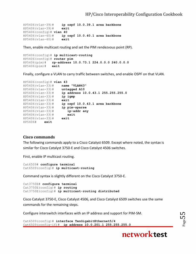
HP/Cisco Interoperability Configuration Cookbook
Pag
e55
HP5406(vlan-39)# ip ospf 10.0.39.1 area backbone
HP5406(vlan-39)# exit
HP5406(config)# vlan 40
HP5406(vlan-40)# ip ospf 10.0.40.1 area backbone
HP5406(vlan-40)# exit
Then, enable multicast routing and set the PIM rendezvous point (RP).
HP5406(config)# ip multicast-routing
HP5406(config)# router pim
HP5406(pim)# rp-address 10.0.73.1 224.0.0.0 240.0.0.0
HP5406(pim)# exit
Finally, configure a VLAN to carry traffic between switches, and enable OSPF on that VLAN.
HP5406(config)# vlan 43
HP5406(vlan-33)# name "VLAN43"
HP5406(vlan-33)# untagged A10
HP5406(vlan-33)# ip address 10.0.43.1 255.255.255.0
HP5406(vlan-33)# ip igmp
HP5406(vlan-33)# exit
HP5406(vlan-33)# ip ospf 10.0.43.1 area backbone
HP5406(vlan-33)# ip pim-sparse
HP5406(vlan-33)# ip-addr any
HP5406(vlan-33)# exit
HP5406(vlan-33)# exit
HP5406# exit
Cisco commands
The following commands apply to a Cisco Catalyst 6509. Except where noted, the syntax is
similar for Cisco Catalyst 3750-E and Cisco Catalyst 4506 switches.
First, enable IP multicast routing.
Cat6509# configure terminal
Cat6509(config)# ip multicast-routing
Command syntax is slightly different on the Cisco Catalyst 3750-E.
Cat3750E# configure terminal
Cat3750E(config)# ip routing
Cat3750E(config)# ip multicast-routing distributed
Cisco Catalyst 3750-E, Cisco Catalyst 4506, and Cisco Catalyst 6509 switches use the same
commands for the remaining steps.
Configure interswitch interfaces with an IP address and support for PIM-SM.
Cat6509(config)# interface TenGigabitEthernet5/4
Cat6509(config-if)# ip address 10.0.201.1 255.255.255.0
HP/Cisco Interoperability Configuration Cookbook
Pag
e56
Cat6509(config-if)# ip pim sparse-mode
Cat6509(config-if)# exit
Then, enable OSPF. Although OSPF is not strictly necessary for IP multicast forwarding, some
unicast routing protocol or static routing is required.
Cat6509(config)# router ospf 1
Cat6509(config-router)# log-adjacency-changes
Cat6509(config-router)# network 10.0.0.0 0.0.255.255 area 0
Cat6509(config-router)# exit
4. Configure a PIM rendezvous point (RP). In the case the RP will be on the HP A9505.
Cat6509(config)# ip pim rp-address 10.0.73.1
Cat6509(config)# end
Validation
Once subscribers attached to the HP switches have joined multicast groups by sending IGMP
reports with join messages, any multicast traffic for these groups offered to Interface VLAN73
on the HP9505 will be forward to all subscriber ports on the HP switches.
The HP A-series command display ip multicast routing-table will verify that the
HP A5800 and Cisco devices see one another and can exchange multicast information. The HP
E-series command show ip mrouter provides the same verification for HP E5406zl
Ethernet switches.
Virtual router redundancy protocol (VRRP) interoperability
Objective
To validate failover functionality of the virtual router redundancy protocol (VRRP) between HP
Networking and Cisco Catalyst switches configured as routers.
Background
Two or more routers can make use of VRRP to add redundancy and enhance network
availability. With VRRP, all routers share a single virtual IP address. One router acts as the
master (active) device, while all others act as backups. If the master router fails (or if a link fails
on the interfaces configured with the virtual IP address), one of the backup routers takes over
as master.
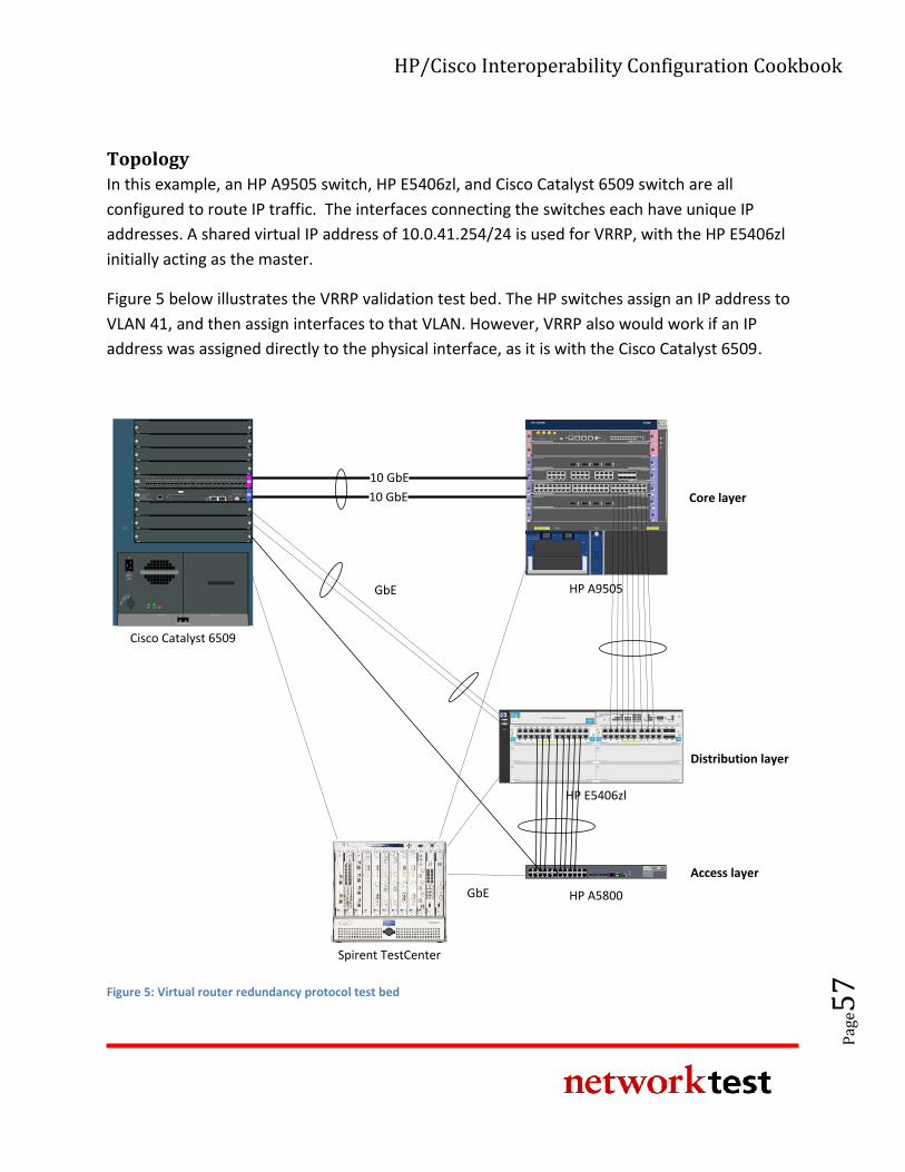
HP/Cisco Interoperability Configuration Cookbook
Pag
e57
Topology
In this example, an HP A9505 switch, HP E5406zl, and Cisco Catalyst 6509 switch are all
configured to route IP traffic. The interfaces connecting the switches each have unique IP
addresses. A shared virtual IP address of 10.0.41.254/24 is used for VRRP, with the HP E5406zl
initially acting as the master.
Figure 5 below illustrates the VRRP validation test bed. The HP switches assign an IP address to
VLAN 41, and then assign interfaces to that VLAN. However, VRRP also would work if an IP
address was assigned directly to the physical interface, as it is with the Cisco Catalyst 6509.
10 GbE
FANSTATUS
1
2
3
4
5
6
7
8
9
Power Supply 1 Power Supply 2
Catalyst 6500 SERIES
Cisco Catalyst 6509
100-240 V~16 A
60/50 Hz
INPUTOK
FANOK
OUTPUTFAIL
RUNIN
STALL
INPUT
WS-X6748-SFP
48 PORT GIGABIT ETHERNET SFP
STATUS
1 2 3 4 5 6 7 8 9 10 11 12 13 14 15 16 17 18 19 20 21 22 23 24 25 26 27 28 29 30 31 32 33 34 35 36 37 38 39 40 41 42 43 44 45 46 47 48
WS-SUP32-10GE-P3B
CATALYST 6500 SUPERVISOR ENGINE 32
SYSTEM
STATU
S
ACTIV
E
PWR
MG
MT
EJECT
DISK 0CONSOLEPORT 2PORT 1
LINK 1
LINK 2
RESET
TX RX TX RX
LINK
USB 2.0
PORT 3
E S D
This device has more than one power
input. DO disconnect all power inputs
to power off this device.
High leakage current,earth
connection essential before
connecting power supply.PWR2PWR1 POE
RUN
ALM
FAN
0
6
5
4
3
2
1
UP
H3C S9505E
POWER 1: ~100-240V;50/60Hz;16A
POWER 2: ~100-240V;50/60Hz;16A
POWER 1
POWER 2
ON1 OFF1 ON2 OFF2
10GBASE-R/W-XFP
21LINK
ACT
LINK
ACT
LSR1XP2LEB1
CF CARD
CLKIN
CLKO
UT C
FS
MG
MNT
ACT
LINK
RS232/485
CO
NSO
LE
AUX
RESET
USB
DEV U
SBS
HO
ST
LSR1SRP2C1
ALM
SFSAC
TRUN
LPU
5 6 7 8 90 1 2 3 4 10 11 12 13
LSR2GV48REB110/100/1000BASE-T-RJ45
1 2 3 4 5 6 7 8 9 10 11 12 13 14 15 16 17 18 19 20 21 22 23 24 25 26 27 28 29 30 31 32 33 34 35 36 37 38 39 40 41 42 43 44 45 46 47 48
48
47
2
1
15
16
17
18
31
32
33
34 LINK/ACTLINK/ACT
LINK/ACT
1 2 3 4 5 6 7 8 9 10 11 12 13 14 15 16 17 18 19 20 21 22 23 24
LINK/ACT
25 26 27 28 29 30 31 32
LSR1GT24LEC110/100/1000BASE-T-RJ45 COMBO
8
7
2
1
16
15
10
9
24
23
18
17
26
25
32
31
10GBASE-R/W-XFP LSR1XP4LEC1
3 421LINK
ACT
LINK
ACT
LINK
ACT
LINK
ACT
10GBASE-R/W-XFP
3 421LINK
ACT
LINK
ACT
LINK
ACT
LINK
ACT
LSR1XP4LEB1
H3C S5800 Series
SFP+10/100/1000Base-T
Speed:Green = 1000Mbps, Yellow = 10/100Mbps
Console
11 129 107 85 63 41 2 13 14 15 16 17 18 19 20 21 22 23 24
25 26 27 28
Green=10Gbps, Yellow=1Gbps
Duplex: Green=Full Duplex, Yellow =Half Duplex
SYS
RPS
SLOT1
Mode
Y ellow = Duplex
UnitGreen = Speed
zlmodule
ModuleStatus
ModuleLocator
HDDActivityModule
Shutdown
NetworkActivity
ONE Services Module
USB
Link/Act
Managment10/100/1000T
PCIe 1
PCIe 2
Avaya Aura SBCpowered by Acme Packet
TM
HP ONEExt Svcszl ModuleJ9543A
zlmodule
ModuleStatus
ModuleLocator
HDDActivityModule
Shutdown
NetworkActivity
ONE Services Module
USB
Link/Act
Managment10/100/1000T
PCIe 1
PCIe 2
Avaya Aura SBCpowered by Acme Packet
TM
HP ONEExt Svcszl ModuleJ9543A
Spirent TestCenter
HP A5800
HP A9505
Power
Fault
Locator
E F
C D
A
ProCurve NetworkingHP Innovation
zlProCurve
24p Gig-T
zl Module
J8702A PoE-Integrated 10/100/1000Base-T Ports (1-24) - Ports are IEEE Auto MDI/MDI-X
1 5
62
3
4
7 11
128
9
10
13 17
1814
15
16
19 23
2420
21
22 zlProCurve
24p Gig-T
zl Module
J8702A PoE-Integrated 10/100/1000Base-T Ports (1-24) - Ports are IEEE Auto MDI/MDI-X
1 5
62
3
4
7 11
128
9
10
13 17
1814
15
16
19 23
2420
21
22
ConsoleReset Clear
Auxiliary Port
ProCurve Switch 5400zl
Management Module
J8726A
Internal
PowerPoE
Pwr
2
1
2
4
1
3
PoE
Temp
Fan
Flash
DIMM
Mgmt
ChasTest
LED ModeModules
Status
Act
FDx
Spd Usr
PoE
H
J
LK
I
G
F
D
B
E
C
A
ProCurve
Switch 5406zl
J8699A PoE
Use
zl Modules
only
B
ProCurve
Switch 5406zl
J9447A
zlProCurve
Gig-T/SFP
zl Module
J9308A PoE-Integrated 10/100/1000Base-T Ports (1-24) - Ports are Auto MDIX
1 5
62
3
4
7 11
128
9
10
13 17
1814
15
16
19
20
23
24
21
22
Use only
HP ProCurve
SFPs
zlProCurve
Gig-T PoE+
zl Module
J9307A PoE-Integrated 10/100/1000Base-T Ports (1-24) - Ports are Auto MDIX
1 5
62
3
4
7 11
128
9
10
13 17
1814
15
16
19 23
2420
21
22
HP ProCurve Networking
HP E5406zl
GbE
GbE
Core layer
Distribution layer
Access layer
10 GbE
Figure 5: Virtual router redundancy protocol test bed
HP/Cisco Interoperability Configuration Cookbook
Pag
e58
HP A-series commands
VRRP configuration is done in the interface configuration context. Here, it is done on the VLAN
interface.
<HP9505> system-view
[HP9505] interface Vlan-interface41
[HP9505-Vlan-interface41] ip address 10.0.41.1 255.255.255.0
[HP9505-Vlan-interface41] vrrp vrid 1 virtual-ip 10.0.41.254
[HP9505-Vlan-interface41] vrrp vrid 1 priority 254
[HP9505-Vlan-interface41] quit
[HP9505] quit
HP E-series commands
First, create and configure the VLAN interface.
HP5406ZL# configure
HP5406ZL(config)# vlan 41
HP5406ZL(vlan-41)# name "VLAN41"
HP5406ZL(vlan-41)# untagged A10
HP5406ZL(vlan-41)# ip address 10.0.41.1 255.255.255.0
HP5406ZL(vlan-41)# exit
Next, configure VRRP.
HP5406ZL(config)# router vrrp
HP5406ZL(config)# vlan 41
HP5406ZL(vlan-41)# vrrp vrid 1
HP5406ZL(vlan-41-vrid-1)# owner
HP5406ZL(vlan-41-vrid-1)# virtual-ip-address 10.0.41.254 255.255.255.0
HP5406ZL(vlan-41-vrid-1)# priority 255
HP5406ZL(vlan-41-vrid-1)# enable
HP5406ZL(vlan-41-vrid-1)# exit
HP5406ZL(vlan-41-vrid-1)# exit
HP5406ZL(vlan-41)# exit
HP5406ZL# exit
Cisco commands
The following commands apply to a Cisco Catalyst 6509. The syntax is similar for Catalyst 3750-E
and Cisco Catalyst 4506 switches.
VRRP configuration is done in the interface configuration context.
Cat6509# configure terminal
Cat6509(config)# interface GigabitEthernet4/21
Cat6509(config-if)# ip address 10.0.41.3 255.255.255.0
HP/Cisco Interoperability Configuration Cookbook
Pag
e59
Cat6509(config-if)# vrrp 1 description VRRP Test
Cat6509(config-if)# vrrp 1 ip 10.0.41.254
Cat6509(config-if)# vrrp 1 timers learn
Cat6509(config-if)# vrrp 1 priority 90
Cat6509(config-if)# end
Validation
Both the HP E5406zl and Cisco Catalyst 6509 support the show vrrp command, which will
indicate the current VRRP state on each system.
HP/Cisco Interoperability Configuration Cookbook
Pag
e60
Appendix A: About Network Test Network Test is an independent third-party test lab and engineering services consultancy. Our core competencies are performance, security,
and conformance assessment of networking equipment and live networks. Our clients include equipment manufacturers, large enterprises,
service providers, industry consortia, and trade publications.
Appendix B: Sample Configuration Files This appendix lists URLs for the HP and Cisco switch files used to verify interoperability. These files are freely available for download from a
public Network Test server.
A copy of this document, a brief interoperability report, and all HP and Cisco configuration files are available at http://networktest.com/hpiop.
Appendix C: Software Releases Tested This appendix describes the software versions used on the test bed. All tests were conducted in March 2011 at Network Test’s facility in
Westlake Village, CA, USA.
Component Version
HP A9505 5.20, Release 1238P08
HP E5406zl K.15.03.0007
HP A5800 5.20, Release 1206
Cisco Catalyst 6509 12.2(33)SXI2a
Cisco Catalyst 4506 12.2(20)EWA
Cisco Catalyst 3750-E 12.2(55)SE1
Spirent TestCenter 3.55.5086.0000
Appendix D: Disclaimer Network Test Inc. has made every attempt to ensure that all test procedures were conducted with the utmost precision and accuracy, but acknowledges that errors do occur. Network Test Inc. shall not be held liable for damages which may result for the use of information contained in this document. All trademarks mentioned in this document are property of their respective owners.
Network Test Inc. 31324 Via Colinas, Suite 113 Westlake Village, CA 91362-6761 USA +1-818-889-0011 http://networktest.com [email protected]
Recommended