
Informatica PowerCenter Express (Version 9.5.1)
User Guide
Informatica PowerCenter Express User Guide
Version 9.5.1April 2013
Copyright (c) 1998-2013 Informatica Corporation. All rights reserved.
This software and documentation contain proprietary information of Informatica Corporation and are provided under a license agreement containing restrictions on use anddisclosure and are also protected by copyright law. Reverse engineering of the software is prohibited. No part of this document may be reproduced or transmitted in any form, by anymeans (electronic, photocopying, recording or otherwise) without prior consent of Informatica Corporation. This Software may be protected by U.S. and/or international Patents andother Patents Pending.
Use, duplication, or disclosure of the Software by the U.S. Government is subject to the restrictions set forth in the applicable software license agreement and as provided in DFARS227.7202-1(a) and 227.7702-3(a) (1995), DFARS 252.227-7013©(1)(ii) (OCT 1988), FAR 12.212(a) (1995), FAR 52.227-19, or FAR 52.227-14 (ALT III), as applicable.
The information in this product or documentation is subject to change without notice. If you find any problems in this product or documentation, please report them to us inwriting.
Informatica, Informatica Platform, Informatica Data Services, PowerCenter, PowerCenterRT, PowerCenter Connect, PowerCenter Data Analyzer, PowerExchange, PowerMart,Metadata Manager, Informatica Data Quality, Informatica Data Explorer, Informatica B2B Data Transformation, Informatica B2B Data Exchange Informatica On Demand,Informatica Identity Resolution, Informatica Application Information Lifecycle Management, Informatica Complex Event Processing, Ultra Messaging and Informatica Master DataManagement are trademarks or registered trademarks of Informatica Corporation in the United States and in jurisdictions throughout the world. All other company and productnames may be trade names or trademarks of their respective owners.
Portions of this software and/or documentation are subject to copyright held by third parties, including without limitation: Copyright DataDirect Technologies. All rights reserved.Copyright © Sun Microsystems. All rights reserved. Copyright © RSA Security Inc. All Rights Reserved. Copyright © Ordinal Technology Corp. All rights reserved.Copyright ©Aandacht c.v. All rights reserved. Copyright Genivia, Inc. All rights reserved. Copyright Isomorphic Software. All rights reserved. Copyright © Meta Integration Technology, Inc. Allrights reserved. Copyright © Intalio. All rights reserved. Copyright © Oracle. All rights reserved. Copyright © Adobe Systems Incorporated. All rights reserved. Copyright © DataArt,Inc. All rights reserved. Copyright © ComponentSource. All rights reserved. Copyright © Microsoft Corporation. All rights reserved. Copyright © Rogue Wave Software, Inc. All rightsreserved. Copyright © Teradata Corporation. All rights reserved. Copyright © Yahoo! Inc. All rights reserved. Copyright © Glyph & Cog, LLC. All rights reserved. Copyright ©Thinkmap, Inc. All rights reserved. Copyright © Clearpace Software Limited. All rights reserved. Copyright © Information Builders, Inc. All rights reserved. Copyright © OSS Nokalva,Inc. All rights reserved. Copyright Edifecs, Inc. All rights reserved. Copyright Cleo Communications, Inc. All rights reserved. Copyright © International Organization forStandardization 1986. All rights reserved. Copyright © ej-technologies GmbH. All rights reserved. Copyright © Jaspersoft Corporation. All rights reserved. Copyright © isInternational Business Machines Corporation. All rights reserved. Copyright © yWorks GmbH. All rights reserved. Copyright © Lucent Technologies. All rights reserved. Copyright(c) University of Toronto. All rights reserved. Copyright © Daniel Veillard. All rights reserved. Copyright © Unicode, Inc. Copyright IBM Corp. All rights reserved. Copyright ©MicroQuill Software Publishing, Inc. All rights reserved. Copyright © PassMark Software Pty Ltd. All rights reserved. Copyright © LogiXML, Inc. All rights reserved. Copyright ©2003-2010 Lorenzi Davide, All rights reserved. Copyright © Red Hat, Inc. All rights reserved. Copyright © The Board of Trustees of the Leland Stanford Junior University. All rightsreserved. Copyright © EMC Corporation. All rights reserved. Copyright © Flexera Software. All rights reserved. Copyright © Jinfonet Software. All rights reserved. Copyright © AppleInc. All rights reserved.
This product includes software developed by the Apache Software Foundation (http://www.apache.org/), and other software which is licensed under the Apache License, Version2.0 (the "License"). You may obtain a copy of the License at http://www.apache.org/licenses/LICENSE-2.0. Unless required by applicable law or agreed to in writing, softwaredistributed under the License is distributed on an "AS IS" BASIS, WITHOUT WARRANTIES OR CONDITIONS OF ANY KIND, either express or implied. See the License for thespecific language governing permissions and limitations under the License.
This product includes software which was developed by Mozilla (http://www.mozilla.org/), software copyright The JBoss Group, LLC, all rights reserved; software copyright ©1999-2006 by Bruno Lowagie and Paulo Soares and other software which is licensed under various versions of the GNU Lesser General Public License Agreement, which may befound at http:// www.gnu.org/licenses/lgpl.html. The materials are provided free of charge by Informatica, "as-is", without warranty of any kind, either express or implied, includingbut not limited to the implied warranties of merchantability and fitness for a particular purpose.
The product includes ACE(TM) and TAO(TM) software copyrighted by Douglas C. Schmidt and his research group at Washington University, University of California, Irvine, andVanderbilt University, Copyright (©) 1993-2006, all rights reserved.
This product includes software developed by the OpenSSL Project for use in the OpenSSL Toolkit (copyright The OpenSSL Project. All Rights Reserved) and redistribution of thissoftware is subject to terms available at http://www.openssl.org and http://www.openssl.org/source/license.html.
This product includes Curl software which is Copyright 1996-2007, Daniel Stenberg, <[email protected]>. All Rights Reserved. Permissions and limitations regarding this softwareare subject to terms available at http://curl.haxx.se/docs/copyright.html. Permission to use, copy, modify, and distribute this software for any purpose with or without fee is herebygranted, provided that the above copyright notice and this permission notice appear in all copies.
The product includes software copyright 2001-2005 (©) MetaStuff, Ltd. All Rights Reserved. Permissions and limitations regarding this software are subject to terms available athttp://www.dom4j.org/ license.html.
The product includes software copyright © 2004-2007, The Dojo Foundation. All Rights Reserved. Permissions and limitations regarding this software are subject to terms availableat http://dojotoolkit.org/license.
This product includes ICU software which is copyright International Business Machines Corporation and others. All rights reserved. Permissions and limitations regarding thissoftware are subject to terms available at http://source.icu-project.org/repos/icu/icu/trunk/license.html.
This product includes software copyright © 1996-2006 Per Bothner. All rights reserved. Your right to use such materials is set forth in the license which may be found at http://www.gnu.org/software/ kawa/Software-License.html.
This product includes OSSP UUID software which is Copyright © 2002 Ralf S. Engelschall, Copyright © 2002 The OSSP Project Copyright © 2002 Cable & Wireless Deutschland.Permissions and limitations regarding this software are subject to terms available at http://www.opensource.org/licenses/mit-license.php.
This product includes software developed by Boost (http://www.boost.org/) or under the Boost software license. Permissions and limitations regarding this software are subject toterms available at http:/ /www.boost.org/LICENSE_1_0.txt.
This product includes software copyright © 1997-2007 University of Cambridge. Permissions and limitations regarding this software are subject to terms available at http://www.pcre.org/license.txt.
This product includes software copyright © 2007 The Eclipse Foundation. All Rights Reserved. Permissions and limitations regarding this software are subject to terms available athttp://www.eclipse.org/org/documents/epl-v10.php.
This product includes software licensed under the terms at http://www.tcl.tk/software/tcltk/license.html, http://www.bosrup.com/web/overlib/?License, http://www.stlport.org/doc/license.html, http:// asm.ow2.org/license.html, http://www.cryptix.org/LICENSE.TXT, http://hsqldb.org/web/hsqlLicense.html, http://httpunit.sourceforge.net/doc/license.html,http://jung.sourceforge.net/license.txt, http://www.gzip.org/zlib/zlib_license.html, http://www.openldap.org/software/release/license.html, http://www.libssh2.org, http://slf4j.org/license.html, http://www.sente.ch/software/OpenSourceLicense.html, http://fusesource.com/downloads/license-agreements/fuse-message-broker-v-5-3-license-agreement;http://antlr.org/license.html; http://aopalliance.sourceforge.net/; http://www.bouncycastle.org/licence.html; http://www.jgraph.com/jgraphdownload.html; http://www.jcraft.com/jsch/LICENSE.txt; http://jotm.objectweb.org/bsd_license.html; http://www.w3.org/Consortium/Legal/2002/copyright-software-20021231; http://www.slf4j.org/license.html; http://nanoxml.sourceforge.net/orig/copyright.html; http://www.json.org/license.html; http://forge.ow2.org/projects/javaservice/, http://www.postgresql.org/about/licence.html, http://

www.sqlite.org/copyright.html, http://www.tcl.tk/software/tcltk/license.html, http://www.jaxen.org/faq.html, http://www.jdom.org/docs/faq.html, http://www.slf4j.org/license.html;http://www.iodbc.org/dataspace/iodbc/wiki/iODBC/License; http://www.keplerproject.org/md5/license.html; http://www.toedter.com/en/jcalendar/license.html; http://www.edankert.com/bounce/index.html; http://www.net-snmp.org/about/license.html; http://www.openmdx.org/#FAQ; http://www.php.net/license/3_01.txt; http://srp.stanford.edu/license.txt; http://www.schneier.com/blowfish.html; http://www.jmock.org/license.html; http://xsom.java.net; and http://benalman.com/about/license/; https://github.com/CreateJS/EaselJS/blob/master/src/easeljs/display/Bitmap.js; http://www.h2database.com/html/license.html#summary.
This product includes software licensed under the Academic Free License (http://www.opensource.org/licenses/afl-3.0.php), the Common Development and Distribution License(http://www.opensource.org/licenses/cddl1.php) the Common Public License (http://www.opensource.org/licenses/cpl1.0.php), the Sun Binary Code License AgreementSupplemental License Terms, the BSD License (http:// www.opensource.org/licenses/bsd-license.php) the MIT License (http://www.opensource.org/licenses/mit-license.php) andthe Artistic License (http://www.opensource.org/licenses/artistic-license-1.0).
This product includes software copyright © 2003-2006 Joe WaInes, 2006-2007 XStream Committers. All rights reserved. Permissions and limitations regarding this software aresubject to terms available at http://xstream.codehaus.org/license.html. This product includes software developed by the Indiana University Extreme! Lab. For further informationplease visit http://www.extreme.indiana.edu/.
This Software is protected by U.S. Patent Numbers 5,794,246; 6,014,670; 6,016,501; 6,029,178; 6,032,158; 6,035,307; 6,044,374; 6,092,086; 6,208,990; 6,339,775; 6,640,226;6,789,096; 6,820,077; 6,823,373; 6,850,947; 6,895,471; 7,117,215; 7,162,643; 7,243,110, 7,254,590; 7,281,001; 7,421,458; 7,496,588; 7,523,121; 7,584,422; 7676516; 7,720,842; 7,721,270; and 7,774,791, international Patents and other Patents Pending.
DISCLAIMER: Informatica Corporation provides this documentation "as is" without warranty of any kind, either express or implied, including, but not limited to, the impliedwarranties of noninfringement, merchantability, or use for a particular purpose. Informatica Corporation does not warrant that this software or documentation is error free. Theinformation provided in this software or documentation may include technical inaccuracies or typographical errors. The information in this software and documentation is subject tochange at any time without notice.
NOTICES
This Informatica product (the "Software") includes certain drivers (the "DataDirect Drivers") from DataDirect Technologies, an operating company of Progress Software Corporation("DataDirect") which are subject to the following terms and conditions:
1.THE DATADIRECT DRIVERS ARE PROVIDED "AS IS" WITHOUT WARRANTY OF ANY KIND, EITHER EXPRESSED OR IMPLIED, INCLUDING BUT NOT LIMITEDTO, THE IMPLIED WARRANTIES OF MERCHANTABILITY, FITNESS FOR A PARTICULAR PURPOSE AND NON-INFRINGEMENT.
2. IN NO EVENT WILL DATADIRECT OR ITS THIRD PARTY SUPPLIERS BE LIABLE TO THE END-USER CUSTOMER FOR ANY DIRECT, INDIRECT, INCIDENTAL,SPECIAL, CONSEQUENTIAL OR OTHER DAMAGES ARISING OUT OF THE USE OF THE ODBC DRIVERS, WHETHER OR NOT INFORMED OF THEPOSSIBILITIES OF DAMAGES IN ADVANCE. THESE LIMITATIONS APPLY TO ALL CAUSES OF ACTION, INCLUDING, WITHOUT LIMITATION, BREACH OFCONTRACT, BREACH OF WARRANTY, NEGLIGENCE, STRICT LIABILITY, MISREPRESENTATION AND OTHER TORTS.
Part Number: PCX-DUG-95100-0001
Table of Contents
Preface . . . . . . . . . . . . . . . . . . . . . . . . . . . . . . . . . . . . . . . . . . . . . . . . . . . . . . . . . . . . . . . . . . . . . . . . . . ixInformatica Resources. . . . . . . . . . . . . . . . . . . . . . . . . . . . . . . . . . . . . . . . . . . . . . . . . . . . . . ix
Informatica MySupport Portal. . . . . . . . . . . . . . . . . . . . . . . . . . . . . . . . . . . . . . . . . . . . . . . ix
Informatica Documentation. . . . . . . . . . . . . . . . . . . . . . . . . . . . . . . . . . . . . . . . . . . . . . . . ix
Informatica Web Site. . . . . . . . . . . . . . . . . . . . . . . . . . . . . . . . . . . . . . . . . . . . . . . . . . . . ix
Informatica Marketplace. . . . . . . . . . . . . . . . . . . . . . . . . . . . . . . . . . . . . . . . . . . . . . . . . . ix
Chapter 1: Informatica Developer. . . . . . . . . . . . . . . . . . . . . . . . . . . . . . . . . . . . . . . . . . . . . . . . . . 1Informatica Developer Overview. . . . . . . . . . . . . . . . . . . . . . . . . . . . . . . . . . . . . . . . . . . . . . . . 1
Start Informatica Developer. . . . . . . . . . . . . . . . . . . . . . . . . . . . . . . . . . . . . . . . . . . . . . . . . . . 1
Starting a Local Developer Tool Installation. . . . . . . . . . . . . . . . . . . . . . . . . . . . . . . . . . . . . . 2
Starting a Remote Developer Tool Installation. . . . . . . . . . . . . . . . . . . . . . . . . . . . . . . . . . . . 2
Informatica Developer User Interface. . . . . . . . . . . . . . . . . . . . . . . . . . . . . . . . . . . . . . . . . . . . . 3
Informatica Developer Welcome Page. . . . . . . . . . . . . . . . . . . . . . . . . . . . . . . . . . . . . . . . . 4
Cheat Sheets. . . . . . . . . . . . . . . . . . . . . . . . . . . . . . . . . . . . . . . . . . . . . . . . . . . . . . . . . 5
Informatica Preferences. . . . . . . . . . . . . . . . . . . . . . . . . . . . . . . . . . . . . . . . . . . . . . . . . . 5
Informatica Marketplace. . . . . . . . . . . . . . . . . . . . . . . . . . . . . . . . . . . . . . . . . . . . . . . . . . 5
Setting Up Informatica Developer. . . . . . . . . . . . . . . . . . . . . . . . . . . . . . . . . . . . . . . . . . . . . . . 5
Step 1. Adding the Domain and Repository. . . . . . . . . . . . . . . . . . . . . . . . . . . . . . . . . . . . . . 6
Step 2. Select the Default Data Integration Service. . . . . . . . . . . . . . . . . . . . . . . . . . . . . . . . . 9
The Model Repository. . . . . . . . . . . . . . . . . . . . . . . . . . . . . . . . . . . . . . . . . . . . . . . . . . . . . . 10
Objects in Informatica Developer. . . . . . . . . . . . . . . . . . . . . . . . . . . . . . . . . . . . . . . . . . . . 10
Object Properties. . . . . . . . . . . . . . . . . . . . . . . . . . . . . . . . . . . . . . . . . . . . . . . . . . . . . . 11
Connecting to a Model Repository. . . . . . . . . . . . . . . . . . . . . . . . . . . . . . . . . . . . . . . . . . . 11
Projects. . . . . . . . . . . . . . . . . . . . . . . . . . . . . . . . . . . . . . . . . . . . . . . . . . . . . . . . . . . . . . . 12
Creating a Project. . . . . . . . . . . . . . . . . . . . . . . . . . . . . . . . . . . . . . . . . . . . . . . . . . . . . . 12
Filter Projects. . . . . . . . . . . . . . . . . . . . . . . . . . . . . . . . . . . . . . . . . . . . . . . . . . . . . . . . 13
Project Permissions. . . . . . . . . . . . . . . . . . . . . . . . . . . . . . . . . . . . . . . . . . . . . . . . . . . . . . . 13
Permissions for External Objects. . . . . . . . . . . . . . . . . . . . . . . . . . . . . . . . . . . . . . . . . . . . 14
Permissions for Dependent Object Instances. . . . . . . . . . . . . . . . . . . . . . . . . . . . . . . . . . . . 14
Parent Object Access. . . . . . . . . . . . . . . . . . . . . . . . . . . . . . . . . . . . . . . . . . . . . . . . . . . 15
Assigning Permissions. . . . . . . . . . . . . . . . . . . . . . . . . . . . . . . . . . . . . . . . . . . . . . . . . . . 15
Folders. . . . . . . . . . . . . . . . . . . . . . . . . . . . . . . . . . . . . . . . . . . . . . . . . . . . . . . . . . . . . . . 16
Creating a Folder. . . . . . . . . . . . . . . . . . . . . . . . . . . . . . . . . . . . . . . . . . . . . . . . . . . . . . 16
Search. . . . . . . . . . . . . . . . . . . . . . . . . . . . . . . . . . . . . . . . . . . . . . . . . . . . . . . . . . . . . . . . 16
Searching for Objects and Properties. . . . . . . . . . . . . . . . . . . . . . . . . . . . . . . . . . . . . . . . . 17
Workspace Editor. . . . . . . . . . . . . . . . . . . . . . . . . . . . . . . . . . . . . . . . . . . . . . . . . . . . . . . . . 17
Find in Editor. . . . . . . . . . . . . . . . . . . . . . . . . . . . . . . . . . . . . . . . . . . . . . . . . . . . . . . . . 18
Table of Contents i
Validation Preferences. . . . . . . . . . . . . . . . . . . . . . . . . . . . . . . . . . . . . . . . . . . . . . . . . . . . . 19
Grouping Error Messages. . . . . . . . . . . . . . . . . . . . . . . . . . . . . . . . . . . . . . . . . . . . . . . . 19
Limiting Error Messages. . . . . . . . . . . . . . . . . . . . . . . . . . . . . . . . . . . . . . . . . . . . . . . . . 19
Copy. . . . . . . . . . . . . . . . . . . . . . . . . . . . . . . . . . . . . . . . . . . . . . . . . . . . . . . . . . . . . . . . . 19
Copying an Object. . . . . . . . . . . . . . . . . . . . . . . . . . . . . . . . . . . . . . . . . . . . . . . . . . . . . 20
Saving a Copy of an Object. . . . . . . . . . . . . . . . . . . . . . . . . . . . . . . . . . . . . . . . . . . . . . . 20
Chapter 2: Connections. . . . . . . . . . . . . . . . . . . . . . . . . . . . . . . . . . . . . . . . . . . . . . . . . . . . . . . . . . 21Connections Overview. . . . . . . . . . . . . . . . . . . . . . . . . . . . . . . . . . . . . . . . . . . . . . . . . . . . . . 21
IBM DB2 Connection Properties. . . . . . . . . . . . . . . . . . . . . . . . . . . . . . . . . . . . . . . . . . . . . . . 23
JDBC Connection Properties. . . . . . . . . . . . . . . . . . . . . . . . . . . . . . . . . . . . . . . . . . . . . . . . . . 24
Microsoft SQL Server Connection Properties. . . . . . . . . . . . . . . . . . . . . . . . . . . . . . . . . . . . . . . 24
ODBC Connection Properties. . . . . . . . . . . . . . . . . . . . . . . . . . . . . . . . . . . . . . . . . . . . . . . . . 26
Oracle Connection Properties. . . . . . . . . . . . . . . . . . . . . . . . . . . . . . . . . . . . . . . . . . . . . . . . . 26
Web Services Connection Properties. . . . . . . . . . . . . . . . . . . . . . . . . . . . . . . . . . . . . . . . . . . . 27
Connection Explorer View. . . . . . . . . . . . . . . . . . . . . . . . . . . . . . . . . . . . . . . . . . . . . . . . . . . 29
Creating Connections. . . . . . . . . . . . . . . . . . . . . . . . . . . . . . . . . . . . . . . . . . . . . . . . . . . . . . 29
Showing Connections. . . . . . . . . . . . . . . . . . . . . . . . . . . . . . . . . . . . . . . . . . . . . . . . . . . . . . 30
Editing a Connection. . . . . . . . . . . . . . . . . . . . . . . . . . . . . . . . . . . . . . . . . . . . . . . . . . . . . . . 31
Copying a Connection. . . . . . . . . . . . . . . . . . . . . . . . . . . . . . . . . . . . . . . . . . . . . . . . . . . . . . 31
Deleting a Connection. . . . . . . . . . . . . . . . . . . . . . . . . . . . . . . . . . . . . . . . . . . . . . . . . . . . . . 32
Refreshing the Connections List. . . . . . . . . . . . . . . . . . . . . . . . . . . . . . . . . . . . . . . . . . . . . . . 32
Chapter 3: Physical Data Objects. . . . . . . . . . . . . . . . . . . . . . . . . . . . . . . . . . . . . . . . . . . . . . . . . 33Physical Data Objects Overview. . . . . . . . . . . . . . . . . . . . . . . . . . . . . . . . . . . . . . . . . . . . . . . 33
Relational Data Objects. . . . . . . . . . . . . . . . . . . . . . . . . . . . . . . . . . . . . . . . . . . . . . . . . . . . . 34
Key Relationships. . . . . . . . . . . . . . . . . . . . . . . . . . . . . . . . . . . . . . . . . . . . . . . . . . . . . . 34
Creating a Read Transformation from Relational Data Objects. . . . . . . . . . . . . . . . . . . . . . . . . 35
Importing a Relational Data Object. . . . . . . . . . . . . . . . . . . . . . . . . . . . . . . . . . . . . . . . . . . 36
Customized Data Objects. . . . . . . . . . . . . . . . . . . . . . . . . . . . . . . . . . . . . . . . . . . . . . . . . . . . 36
Key Relationships. . . . . . . . . . . . . . . . . . . . . . . . . . . . . . . . . . . . . . . . . . . . . . . . . . . . . . 37
Customized Data Object Write Properties. . . . . . . . . . . . . . . . . . . . . . . . . . . . . . . . . . . . . . 39
Creating a Customized Data Object. . . . . . . . . . . . . . . . . . . . . . . . . . . . . . . . . . . . . . . . . . 39
Adding Relational Resources to a Customized Data Object. . . . . . . . . . . . . . . . . . . . . . . . . . . 40
Adding Relational Data Objects to a Customized Data Object. . . . . . . . . . . . . . . . . . . . . . . . . . 40
Custom Queries. . . . . . . . . . . . . . . . . . . . . . . . . . . . . . . . . . . . . . . . . . . . . . . . . . . . . . . . . . 41
Creating a Custom Query. . . . . . . . . . . . . . . . . . . . . . . . . . . . . . . . . . . . . . . . . . . . . . . . . 41
Default Query. . . . . . . . . . . . . . . . . . . . . . . . . . . . . . . . . . . . . . . . . . . . . . . . . . . . . . . . 41
Hints. . . . . . . . . . . . . . . . . . . . . . . . . . . . . . . . . . . . . . . . . . . . . . . . . . . . . . . . . . . . . . 42
Select Distinct. . . . . . . . . . . . . . . . . . . . . . . . . . . . . . . . . . . . . . . . . . . . . . . . . . . . . . . . 44
Filters. . . . . . . . . . . . . . . . . . . . . . . . . . . . . . . . . . . . . . . . . . . . . . . . . . . . . . . . . . . . . 44
Sorted Ports. . . . . . . . . . . . . . . . . . . . . . . . . . . . . . . . . . . . . . . . . . . . . . . . . . . . . . . . . 45
User-Defined Joins. . . . . . . . . . . . . . . . . . . . . . . . . . . . . . . . . . . . . . . . . . . . . . . . . . . . . 45
ii Table of Contents
Outer Join Support. . . . . . . . . . . . . . . . . . . . . . . . . . . . . . . . . . . . . . . . . . . . . . . . . . . . . 47
Informatica Join Syntax. . . . . . . . . . . . . . . . . . . . . . . . . . . . . . . . . . . . . . . . . . . . . . . . . . 47
Pre- and Post-Mapping SQL Commands. . . . . . . . . . . . . . . . . . . . . . . . . . . . . . . . . . . . . . . 50
Flat File Data Objects. . . . . . . . . . . . . . . . . . . . . . . . . . . . . . . . . . . . . . . . . . . . . . . . . . . . . . 51
Flat File Data Object Overview Properties. . . . . . . . . . . . . . . . . . . . . . . . . . . . . . . . . . . . . . 51
Flat File Data Object Read Properties. . . . . . . . . . . . . . . . . . . . . . . . . . . . . . . . . . . . . . . . . 52
Flat File Data Object Write Properties. . . . . . . . . . . . . . . . . . . . . . . . . . . . . . . . . . . . . . . . . 56
Flat File Data Object Advanced Properties. . . . . . . . . . . . . . . . . . . . . . . . . . . . . . . . . . . . . . 58
Creating a Flat File Data Object. . . . . . . . . . . . . . . . . . . . . . . . . . . . . . . . . . . . . . . . . . . . . 59
Importing a Fixed-Width Flat File Data Object. . . . . . . . . . . . . . . . . . . . . . . . . . . . . . . . . . . . 60
Importing a Delimited Flat File Data Object. . . . . . . . . . . . . . . . . . . . . . . . . . . . . . . . . . . . . 60
WSDL Data Object . . . . . . . . . . . . . . . . . . . . . . . . . . . . . . . . . . . . . . . . . . . . . . . . . . . . . . . . 62
WSDL Data Object Overview View. . . . . . . . . . . . . . . . . . . . . . . . . . . . . . . . . . . . . . . . . . . 62
WSDL Data Object Advanced View. . . . . . . . . . . . . . . . . . . . . . . . . . . . . . . . . . . . . . . . . . 63
Importing a WSDL Data Object. . . . . . . . . . . . . . . . . . . . . . . . . . . . . . . . . . . . . . . . . . . . . 63
WSDL Synchronization. . . . . . . . . . . . . . . . . . . . . . . . . . . . . . . . . . . . . . . . . . . . . . . . . . 63
Certificate Management. . . . . . . . . . . . . . . . . . . . . . . . . . . . . . . . . . . . . . . . . . . . . . . . . . 64
Synchronization. . . . . . . . . . . . . . . . . . . . . . . . . . . . . . . . . . . . . . . . . . . . . . . . . . . . . . . . . . 65
Troubleshooting Physical Data Objects. . . . . . . . . . . . . . . . . . . . . . . . . . . . . . . . . . . . . . . . . . . 65
Chapter 4: Schema Object. . . . . . . . . . . . . . . . . . . . . . . . . . . . . . . . . . . . . . . . . . . . . . . . . . . . . . . . 67Schema Object Overview. . . . . . . . . . . . . . . . . . . . . . . . . . . . . . . . . . . . . . . . . . . . . . . . . . . . 67
Schema Object Overview View. . . . . . . . . . . . . . . . . . . . . . . . . . . . . . . . . . . . . . . . . . . . . . . . 67
Schema Files. . . . . . . . . . . . . . . . . . . . . . . . . . . . . . . . . . . . . . . . . . . . . . . . . . . . . . . . 68
Schema Object Schema View. . . . . . . . . . . . . . . . . . . . . . . . . . . . . . . . . . . . . . . . . . . . . . . . . 68
Namespace Properties. . . . . . . . . . . . . . . . . . . . . . . . . . . . . . . . . . . . . . . . . . . . . . . . . . 68
Element Properties. . . . . . . . . . . . . . . . . . . . . . . . . . . . . . . . . . . . . . . . . . . . . . . . . . . . . 69
Simple Type Properties. . . . . . . . . . . . . . . . . . . . . . . . . . . . . . . . . . . . . . . . . . . . . . . . . . 70
Complex Type Properties . . . . . . . . . . . . . . . . . . . . . . . . . . . . . . . . . . . . . . . . . . . . . . . . 71
Attribute Properties. . . . . . . . . . . . . . . . . . . . . . . . . . . . . . . . . . . . . . . . . . . . . . . . . . . . . 72
Schema Object Advanced View. . . . . . . . . . . . . . . . . . . . . . . . . . . . . . . . . . . . . . . . . . . . . . . . 72
Importing a Schema Object. . . . . . . . . . . . . . . . . . . . . . . . . . . . . . . . . . . . . . . . . . . . . . . . . . 73
Schema Changes. . . . . . . . . . . . . . . . . . . . . . . . . . . . . . . . . . . . . . . . . . . . . . . . . . . . . . . . . 73
Schema Synchronization. . . . . . . . . . . . . . . . . . . . . . . . . . . . . . . . . . . . . . . . . . . . . . . . . 74
Schema File Edits. . . . . . . . . . . . . . . . . . . . . . . . . . . . . . . . . . . . . . . . . . . . . . . . . . . . . 74
Certificate Management. . . . . . . . . . . . . . . . . . . . . . . . . . . . . . . . . . . . . . . . . . . . . . . . . . . . . 75
Informatica Developer Certificate Properties. . . . . . . . . . . . . . . . . . . . . . . . . . . . . . . . . . . . . 76
Adding Certificates to Informatica Developer. . . . . . . . . . . . . . . . . . . . . . . . . . . . . . . . . . . . 76
Chapter 5: Profiles. . . . . . . . . . . . . . . . . . . . . . . . . . . . . . . . . . . . . . . . . . . . . . . . . . . . . . . . . . . . . . . 77Profiles Overview. . . . . . . . . . . . . . . . . . . . . . . . . . . . . . . . . . . . . . . . . . . . . . . . . . . . . . . . . 77
Column Profiling Process. . . . . . . . . . . . . . . . . . . . . . . . . . . . . . . . . . . . . . . . . . . . . . . . . . . . 77
Column Profile Options. . . . . . . . . . . . . . . . . . . . . . . . . . . . . . . . . . . . . . . . . . . . . . . . . . . . . 78
Table of Contents iii
Rules. . . . . . . . . . . . . . . . . . . . . . . . . . . . . . . . . . . . . . . . . . . . . . . . . . . . . . . . . . . . . . 78
Filtering Options. . . . . . . . . . . . . . . . . . . . . . . . . . . . . . . . . . . . . . . . . . . . . . . . . . . . . . . 78
Sampling Properties. . . . . . . . . . . . . . . . . . . . . . . . . . . . . . . . . . . . . . . . . . . . . . . . . . . . 79
Creating a Profile. . . . . . . . . . . . . . . . . . . . . . . . . . . . . . . . . . . . . . . . . . . . . . . . . . . . . . . . . 79
Profile Views. . . . . . . . . . . . . . . . . . . . . . . . . . . . . . . . . . . . . . . . . . . . . . . . . . . . . . . . . . . . 79
Column Profile Results. . . . . . . . . . . . . . . . . . . . . . . . . . . . . . . . . . . . . . . . . . . . . . . . . . . . . 80
Column Value Properties. . . . . . . . . . . . . . . . . . . . . . . . . . . . . . . . . . . . . . . . . . . . . . . . . 80
Column Pattern Properties. . . . . . . . . . . . . . . . . . . . . . . . . . . . . . . . . . . . . . . . . . . . . . . . 80
Column Statistics Properties. . . . . . . . . . . . . . . . . . . . . . . . . . . . . . . . . . . . . . . . . . . . . . . 81
Exporting Profile Results from Informatica Developer. . . . . . . . . . . . . . . . . . . . . . . . . . . . . . . . . . 81
Synchronizing a Flat File Data Object. . . . . . . . . . . . . . . . . . . . . . . . . . . . . . . . . . . . . . . . . . . . 82
Synchronizing a Relational Data Object. . . . . . . . . . . . . . . . . . . . . . . . . . . . . . . . . . . . . . . . . . . 82
Chapter 6: Logical View of Data. . . . . . . . . . . . . . . . . . . . . . . . . . . . . . . . . . . . . . . . . . . . . . . . . . . 83Logical View of Data Overview. . . . . . . . . . . . . . . . . . . . . . . . . . . . . . . . . . . . . . . . . . . . . . . . 83
Logical Data Object Model Example. . . . . . . . . . . . . . . . . . . . . . . . . . . . . . . . . . . . . . . . . . 83
Developing a Logical View of Data. . . . . . . . . . . . . . . . . . . . . . . . . . . . . . . . . . . . . . . . . . . . . . 84
Logical Data Object Models. . . . . . . . . . . . . . . . . . . . . . . . . . . . . . . . . . . . . . . . . . . . . . . . . . 84
Creating a Logical Data Object Model. . . . . . . . . . . . . . . . . . . . . . . . . . . . . . . . . . . . . . . . . 84
Importing a Logical Data Object Model from a Modeling Tool. . . . . . . . . . . . . . . . . . . . . . . . . . 85
Logical Data Object Model Properties . . . . . . . . . . . . . . . . . . . . . . . . . . . . . . . . . . . . . . . . . . . 86
CA ERwin Data Modeler Import Properties. . . . . . . . . . . . . . . . . . . . . . . . . . . . . . . . . . . . . . 86
IBM Cognos Business Intelligence Reporting - Framework Manager Import Properties. . . . . . . . . 87
SAP BusinessObjects Designer Import Properties. . . . . . . . . . . . . . . . . . . . . . . . . . . . . . . . . 87
Sybase PowerDesigner CDM Import Properties. . . . . . . . . . . . . . . . . . . . . . . . . . . . . . . . . . 89
Sybase PowerDesigner OOM 9.x to 15.x Import Properties. . . . . . . . . . . . . . . . . . . . . . . . . . . 89
Sybase PowerDesigner PDM Import Properties. . . . . . . . . . . . . . . . . . . . . . . . . . . . . . . . . . . 90
XSD Import Properties. . . . . . . . . . . . . . . . . . . . . . . . . . . . . . . . . . . . . . . . . . . . . . . . . . . 91
Logical Data Objects. . . . . . . . . . . . . . . . . . . . . . . . . . . . . . . . . . . . . . . . . . . . . . . . . . . . . . . 92
Logical Data Object Properties. . . . . . . . . . . . . . . . . . . . . . . . . . . . . . . . . . . . . . . . . . . . . 92
Attribute Relationships. . . . . . . . . . . . . . . . . . . . . . . . . . . . . . . . . . . . . . . . . . . . . . . . . . . 92
Creating a Logical Data Object. . . . . . . . . . . . . . . . . . . . . . . . . . . . . . . . . . . . . . . . . . . . . 93
Logical Data Object Mappings. . . . . . . . . . . . . . . . . . . . . . . . . . . . . . . . . . . . . . . . . . . . . . . . . 93
Logical Data Object Read Mappings. . . . . . . . . . . . . . . . . . . . . . . . . . . . . . . . . . . . . . . . . . 93
Logical Data Object Write Mappings. . . . . . . . . . . . . . . . . . . . . . . . . . . . . . . . . . . . . . . . . . 94
Creating a Logical Data Object Mapping. . . . . . . . . . . . . . . . . . . . . . . . . . . . . . . . . . . . . . . 94
Chapter 7: Mappings. . . . . . . . . . . . . . . . . . . . . . . . . . . . . . . . . . . . . . . . . . . . . . . . . . . . . . . . . . . . . 95Mappings Overview. . . . . . . . . . . . . . . . . . . . . . . . . . . . . . . . . . . . . . . . . . . . . . . . . . . . . . . 95
Object Dependency in a Mapping. . . . . . . . . . . . . . . . . . . . . . . . . . . . . . . . . . . . . . . . . . . . 95
Developing a Mapping. . . . . . . . . . . . . . . . . . . . . . . . . . . . . . . . . . . . . . . . . . . . . . . . . . . . . . 96
Creating a Mapping. . . . . . . . . . . . . . . . . . . . . . . . . . . . . . . . . . . . . . . . . . . . . . . . . . . . . . . 96
Mapping Objects. . . . . . . . . . . . . . . . . . . . . . . . . . . . . . . . . . . . . . . . . . . . . . . . . . . . . . . . . 97
iv Table of Contents
Adding Objects to a Mapping. . . . . . . . . . . . . . . . . . . . . . . . . . . . . . . . . . . . . . . . . . . . . . 97
One to One Links. . . . . . . . . . . . . . . . . . . . . . . . . . . . . . . . . . . . . . . . . . . . . . . . . . . . . . 97
One to Many Links. . . . . . . . . . . . . . . . . . . . . . . . . . . . . . . . . . . . . . . . . . . . . . . . . . . . . 98
Linking Ports. . . . . . . . . . . . . . . . . . . . . . . . . . . . . . . . . . . . . . . . . . . . . . . . . . . . . . . . . . . . 98
Manually Linking Ports. . . . . . . . . . . . . . . . . . . . . . . . . . . . . . . . . . . . . . . . . . . . . . . . . . 98
Automatically Linking Ports. . . . . . . . . . . . . . . . . . . . . . . . . . . . . . . . . . . . . . . . . . . . . . . . 99
Rules and Guidelines for Linking Ports. . . . . . . . . . . . . . . . . . . . . . . . . . . . . . . . . . . . . . . . 99
Propagating Port Attributes. . . . . . . . . . . . . . . . . . . . . . . . . . . . . . . . . . . . . . . . . . . . . . . . . . 100
Dependency Types. . . . . . . . . . . . . . . . . . . . . . . . . . . . . . . . . . . . . . . . . . . . . . . . . . . . 100
Link Path Dependencies. . . . . . . . . . . . . . . . . . . . . . . . . . . . . . . . . . . . . . . . . . . . . . . . . 100
Implicit Dependencies. . . . . . . . . . . . . . . . . . . . . . . . . . . . . . . . . . . . . . . . . . . . . . . . . . 101
Propagated Port Attributes by Transformation. . . . . . . . . . . . . . . . . . . . . . . . . . . . . . . . . . . 101
Mapping Validation. . . . . . . . . . . . . . . . . . . . . . . . . . . . . . . . . . . . . . . . . . . . . . . . . . . . . . . 102
Connection Validation. . . . . . . . . . . . . . . . . . . . . . . . . . . . . . . . . . . . . . . . . . . . . . . . . . 102
Expression Validation. . . . . . . . . . . . . . . . . . . . . . . . . . . . . . . . . . . . . . . . . . . . . . . . . . 103
Object Validation. . . . . . . . . . . . . . . . . . . . . . . . . . . . . . . . . . . . . . . . . . . . . . . . . . . . . 103
Validating a Mapping. . . . . . . . . . . . . . . . . . . . . . . . . . . . . . . . . . . . . . . . . . . . . . . . . . . 103
Running a Mapping. . . . . . . . . . . . . . . . . . . . . . . . . . . . . . . . . . . . . . . . . . . . . . . . . . . . . . . 103
Segments. . . . . . . . . . . . . . . . . . . . . . . . . . . . . . . . . . . . . . . . . . . . . . . . . . . . . . . . . . . . . 104
Segments. . . . . . . . . . . . . . . . . . . . . . . . . . . . . . . . . . . . . . . . . . . . . . . . . . . . . . . . . . 104
Chapter 8: Performance Tuning. . . . . . . . . . . . . . . . . . . . . . . . . . . . . . . . . . . . . . . . . . . . . . . . . . 105Optimizer Levels. . . . . . . . . . . . . . . . . . . . . . . . . . . . . . . . . . . . . . . . . . . . . . . . . . . . . . . . . 105
Optimization Methods Overview. . . . . . . . . . . . . . . . . . . . . . . . . . . . . . . . . . . . . . . . . . . . . . . 106
Early Projection Optimization Method. . . . . . . . . . . . . . . . . . . . . . . . . . . . . . . . . . . . . . . . 106
Early Selection Optimization Method. . . . . . . . . . . . . . . . . . . . . . . . . . . . . . . . . . . . . . . . . 106
Predicate Optimization Method. . . . . . . . . . . . . . . . . . . . . . . . . . . . . . . . . . . . . . . . . . . . 107
Cost-Based Optimization Method. . . . . . . . . . . . . . . . . . . . . . . . . . . . . . . . . . . . . . . . . . . 107
Semi-Join Optimization Method. . . . . . . . . . . . . . . . . . . . . . . . . . . . . . . . . . . . . . . . . . . . 108
Full Optimization and Memory Allocation. . . . . . . . . . . . . . . . . . . . . . . . . . . . . . . . . . . . . . . . . 108
Setting the Optimizer Level for a Developer Tool Mapping. . . . . . . . . . . . . . . . . . . . . . . . . . . . . . 109
Setting the Optimizer Level for a Deployed Mapping. . . . . . . . . . . . . . . . . . . . . . . . . . . . . . . . . . 109
Chapter 9: Pushdown Optimization. . . . . . . . . . . . . . . . . . . . . . . . . . . . . . . . . . . . . . . . . . . . . . 110Pushdown Optimization Overview. . . . . . . . . . . . . . . . . . . . . . . . . . . . . . . . . . . . . . . . . . . . . . 110
Pushdown Optimization to Sources. . . . . . . . . . . . . . . . . . . . . . . . . . . . . . . . . . . . . . . . . . . . . 111
Pushdown Optimization to Native Sources. . . . . . . . . . . . . . . . . . . . . . . . . . . . . . . . . . . . . 111
Pushdown Optimization to ODBC Sources. . . . . . . . . . . . . . . . . . . . . . . . . . . . . . . . . . . . . 111
Pushdown Optimization Expressions. . . . . . . . . . . . . . . . . . . . . . . . . . . . . . . . . . . . . . . . . . . . 112
Functions. . . . . . . . . . . . . . . . . . . . . . . . . . . . . . . . . . . . . . . . . . . . . . . . . . . . . . . . . . 112
Operators. . . . . . . . . . . . . . . . . . . . . . . . . . . . . . . . . . . . . . . . . . . . . . . . . . . . . . . . . . 116
Comparing the Output of the Data Integration Service and Sources. . . . . . . . . . . . . . . . . . . . . . . . 116
Table of Contents v
Chapter 10: Mapplets. . . . . . . . . . . . . . . . . . . . . . . . . . . . . . . . . . . . . . . . . . . . . . . . . . . . . . . . . . . 118Mapplets Overview. . . . . . . . . . . . . . . . . . . . . . . . . . . . . . . . . . . . . . . . . . . . . . . . . . . . . . . 118
Mapplet Types. . . . . . . . . . . . . . . . . . . . . . . . . . . . . . . . . . . . . . . . . . . . . . . . . . . . . . . . . . 118
Mapplets and Rules. . . . . . . . . . . . . . . . . . . . . . . . . . . . . . . . . . . . . . . . . . . . . . . . . . . . . . . 119
Mapplet Input and Output. . . . . . . . . . . . . . . . . . . . . . . . . . . . . . . . . . . . . . . . . . . . . . . . . . . 119
Mapplet Input. . . . . . . . . . . . . . . . . . . . . . . . . . . . . . . . . . . . . . . . . . . . . . . . . . . . . . . . 119
Mapplet Output. . . . . . . . . . . . . . . . . . . . . . . . . . . . . . . . . . . . . . . . . . . . . . . . . . . . . . 119
Creating a Mapplet. . . . . . . . . . . . . . . . . . . . . . . . . . . . . . . . . . . . . . . . . . . . . . . . . . . . . . . 120
Validating a Mapplet. . . . . . . . . . . . . . . . . . . . . . . . . . . . . . . . . . . . . . . . . . . . . . . . . . . . . . 120
Chapter 11: Rule and Mapping Profiling. . . . . . . . . . . . . . . . . . . . . . . . . . . . . . . . . . . . . . . . . . 121Rule and Mapping Profiling Overview. . . . . . . . . . . . . . . . . . . . . . . . . . . . . . . . . . . . . . . . . . . 121
Rule Prerequisites. . . . . . . . . . . . . . . . . . . . . . . . . . . . . . . . . . . . . . . . . . . . . . . . . . . . . . . 121
Creating a Rule in Informatica Developer. . . . . . . . . . . . . . . . . . . . . . . . . . . . . . . . . . . . . . 121
Applying a Rule. . . . . . . . . . . . . . . . . . . . . . . . . . . . . . . . . . . . . . . . . . . . . . . . . . . . . . 122
Mapplet and Mapping Profiling Overview. . . . . . . . . . . . . . . . . . . . . . . . . . . . . . . . . . . . . . . . . 122
Generating a Mapping from a Profile. . . . . . . . . . . . . . . . . . . . . . . . . . . . . . . . . . . . . . . . . 122
Running a Profile on a Mapplet or Mapping Object. . . . . . . . . . . . . . . . . . . . . . . . . . . . . . . . 123
Comparing Profiles for Mapping or Mapplet Objects. . . . . . . . . . . . . . . . . . . . . . . . . . . . . . . 123
Chapter 12: Object Import and Export. . . . . . . . . . . . . . . . . . . . . . . . . . . . . . . . . . . . . . . . . . . . 124Object Import and Export Overview. . . . . . . . . . . . . . . . . . . . . . . . . . . . . . . . . . . . . . . . . . . . . 124
Import and Export Objects. . . . . . . . . . . . . . . . . . . . . . . . . . . . . . . . . . . . . . . . . . . . . . . . . . 124
Object Export. . . . . . . . . . . . . . . . . . . . . . . . . . . . . . . . . . . . . . . . . . . . . . . . . . . . . . . . . . . 125
Exporting Objects. . . . . . . . . . . . . . . . . . . . . . . . . . . . . . . . . . . . . . . . . . . . . . . . . . . . . 126
Object Import. . . . . . . . . . . . . . . . . . . . . . . . . . . . . . . . . . . . . . . . . . . . . . . . . . . . . . . . . . . 126
Importing Projects. . . . . . . . . . . . . . . . . . . . . . . . . . . . . . . . . . . . . . . . . . . . . . . . . . . . . 126
Importing Objects. . . . . . . . . . . . . . . . . . . . . . . . . . . . . . . . . . . . . . . . . . . . . . . . . . . . . 127
Chapter 13: Deployment. . . . . . . . . . . . . . . . . . . . . . . . . . . . . . . . . . . . . . . . . . . . . . . . . . . . . . . . . 129Deployment Overview. . . . . . . . . . . . . . . . . . . . . . . . . . . . . . . . . . . . . . . . . . . . . . . . . . . . . 129
Deployment Methods. . . . . . . . . . . . . . . . . . . . . . . . . . . . . . . . . . . . . . . . . . . . . . . . . . . . . . 130
Creating an Application. . . . . . . . . . . . . . . . . . . . . . . . . . . . . . . . . . . . . . . . . . . . . . . . . . . . 130
Deploying an Object to a Data Integration Service. . . . . . . . . . . . . . . . . . . . . . . . . . . . . . . . . . . 131
Deploying an Object to a File. . . . . . . . . . . . . . . . . . . . . . . . . . . . . . . . . . . . . . . . . . . . . . . . . 131
Updating an Application. . . . . . . . . . . . . . . . . . . . . . . . . . . . . . . . . . . . . . . . . . . . . . . . . . . . 131
Importing Application Archives. . . . . . . . . . . . . . . . . . . . . . . . . . . . . . . . . . . . . . . . . . . . . . . . 132
Mapping Deployment Properties. . . . . . . . . . . . . . . . . . . . . . . . . . . . . . . . . . . . . . . . . . . . . . 132
Application Redeployment. . . . . . . . . . . . . . . . . . . . . . . . . . . . . . . . . . . . . . . . . . . . . . . . . . 133
Redeploying an Application. . . . . . . . . . . . . . . . . . . . . . . . . . . . . . . . . . . . . . . . . . . . . . . 134
vi Table of Contents
Chapter 14: Mapping Parameters and Parameter Files. . . . . . . . . . . . . . . . . . . . . . . . . . . . 135Mapping Parameters and Parameter Files Overview. . . . . . . . . . . . . . . . . . . . . . . . . . . . . . . . . . 135
System Parameters. . . . . . . . . . . . . . . . . . . . . . . . . . . . . . . . . . . . . . . . . . . . . . . . . . . . . . . 135
User-Defined Parameters. . . . . . . . . . . . . . . . . . . . . . . . . . . . . . . . . . . . . . . . . . . . . . . . . . . 136
Process to Run Mappings with User-Defined Parameters. . . . . . . . . . . . . . . . . . . . . . . . . . . 136
Where to Create User-Defined Parameters. . . . . . . . . . . . . . . . . . . . . . . . . . . . . . . . . . . . . 137
Creating a User-Defined Parameter. . . . . . . . . . . . . . . . . . . . . . . . . . . . . . . . . . . . . . . . . 137
Where to Assign Parameters. . . . . . . . . . . . . . . . . . . . . . . . . . . . . . . . . . . . . . . . . . . . . . . . . 138
Assigning a Parameter. . . . . . . . . . . . . . . . . . . . . . . . . . . . . . . . . . . . . . . . . . . . . . . . . . 138
Parameter Files. . . . . . . . . . . . . . . . . . . . . . . . . . . . . . . . . . . . . . . . . . . . . . . . . . . . . . . . . 139
Parameter File Structure. . . . . . . . . . . . . . . . . . . . . . . . . . . . . . . . . . . . . . . . . . . . . . . . 139
Project Element. . . . . . . . . . . . . . . . . . . . . . . . . . . . . . . . . . . . . . . . . . . . . . . . . . . . . . 140
Application Element. . . . . . . . . . . . . . . . . . . . . . . . . . . . . . . . . . . . . . . . . . . . . . . . . . . 141
Rules and Guidelines for Parameter Files. . . . . . . . . . . . . . . . . . . . . . . . . . . . . . . . . . . . . . 141
Sample Parameter File. . . . . . . . . . . . . . . . . . . . . . . . . . . . . . . . . . . . . . . . . . . . . . . . . 141
Creating a Parameter File. . . . . . . . . . . . . . . . . . . . . . . . . . . . . . . . . . . . . . . . . . . . . . . . 143
Running a Mapping with a Parameter File. . . . . . . . . . . . . . . . . . . . . . . . . . . . . . . . . . . . . 143
Chapter 15: Tags. . . . . . . . . . . . . . . . . . . . . . . . . . . . . . . . . . . . . . . . . . . . . . . . . . . . . . . . . . . . . . . . 144Tags Overview. . . . . . . . . . . . . . . . . . . . . . . . . . . . . . . . . . . . . . . . . . . . . . . . . . . . . . . . . . 144
Creating a Tag. . . . . . . . . . . . . . . . . . . . . . . . . . . . . . . . . . . . . . . . . . . . . . . . . . . . . . . . . . 144
Assigning a Tag. . . . . . . . . . . . . . . . . . . . . . . . . . . . . . . . . . . . . . . . . . . . . . . . . . . . . . . . . 145
Viewing Tags. . . . . . . . . . . . . . . . . . . . . . . . . . . . . . . . . . . . . . . . . . . . . . . . . . . . . . . . . . . 145
Chapter 16: Viewing Data. . . . . . . . . . . . . . . . . . . . . . . . . . . . . . . . . . . . . . . . . . . . . . . . . . . . . . . . 146Viewing Data Overview. . . . . . . . . . . . . . . . . . . . . . . . . . . . . . . . . . . . . . . . . . . . . . . . . . . . 146
Configurations. . . . . . . . . . . . . . . . . . . . . . . . . . . . . . . . . . . . . . . . . . . . . . . . . . . . . . . . . . 146
Data Viewer Configurations. . . . . . . . . . . . . . . . . . . . . . . . . . . . . . . . . . . . . . . . . . . . . . . 147
Mapping Configurations. . . . . . . . . . . . . . . . . . . . . . . . . . . . . . . . . . . . . . . . . . . . . . . . . 147
Updating the Default Configuration Properties. . . . . . . . . . . . . . . . . . . . . . . . . . . . . . . . . . . 148
Configuration Properties. . . . . . . . . . . . . . . . . . . . . . . . . . . . . . . . . . . . . . . . . . . . . . . . . 148
Troubleshooting Configurations. . . . . . . . . . . . . . . . . . . . . . . . . . . . . . . . . . . . . . . . . . . . 151
Exporting Data. . . . . . . . . . . . . . . . . . . . . . . . . . . . . . . . . . . . . . . . . . . . . . . . . . . . . . . . . . 151
Logs. . . . . . . . . . . . . . . . . . . . . . . . . . . . . . . . . . . . . . . . . . . . . . . . . . . . . . . . . . . . . . . . 151
Log File Format. . . . . . . . . . . . . . . . . . . . . . . . . . . . . . . . . . . . . . . . . . . . . . . . . . . . . . 152
Monitoring Jobs from the Developer Tool. . . . . . . . . . . . . . . . . . . . . . . . . . . . . . . . . . . . . . . . . 152
Appendix A: Datatype Reference. . . . . . . . . . . . . . . . . . . . . . . . . . . . . . . . . . . . . . . . . . . . . . . . 153Datatype Reference Overview. . . . . . . . . . . . . . . . . . . . . . . . . . . . . . . . . . . . . . . . . . . . . . . . 153
Transformation Datatypes. . . . . . . . . . . . . . . . . . . . . . . . . . . . . . . . . . . . . . . . . . . . . . . . . . . 154
Integer Datatypes. . . . . . . . . . . . . . . . . . . . . . . . . . . . . . . . . . . . . . . . . . . . . . . . . . . . . 154
Binary Datatype. . . . . . . . . . . . . . . . . . . . . . . . . . . . . . . . . . . . . . . . . . . . . . . . . . . . . . 156
Table of Contents vii
Date/Time Datatype. . . . . . . . . . . . . . . . . . . . . . . . . . . . . . . . . . . . . . . . . . . . . . . . . . . 156
Decimal and Double Datatypes. . . . . . . . . . . . . . . . . . . . . . . . . . . . . . . . . . . . . . . . . . . . 157
String Datatypes. . . . . . . . . . . . . . . . . . . . . . . . . . . . . . . . . . . . . . . . . . . . . . . . . . . . . . 158
Flat File and Transformation Datatypes. . . . . . . . . . . . . . . . . . . . . . . . . . . . . . . . . . . . . . . . . . 158
IBM DB2 and Transformation Datatypes. . . . . . . . . . . . . . . . . . . . . . . . . . . . . . . . . . . . . . . . . 159
Unsupported IBM DB2 Datatypes. . . . . . . . . . . . . . . . . . . . . . . . . . . . . . . . . . . . . . . . . . . 159
JDBC and Transformation Datatypes. . . . . . . . . . . . . . . . . . . . . . . . . . . . . . . . . . . . . . . . . . . 160
Microsoft SQL Server and Transformation Datatypes. . . . . . . . . . . . . . . . . . . . . . . . . . . . . . . . . 161
Unsupported Microsoft SQL Server Datatypes. . . . . . . . . . . . . . . . . . . . . . . . . . . . . . . . . . . 162
ODBC and Transformation Datatypes. . . . . . . . . . . . . . . . . . . . . . . . . . . . . . . . . . . . . . . . . . . 163
Oracle and Transformation Datatypes. . . . . . . . . . . . . . . . . . . . . . . . . . . . . . . . . . . . . . . . . . . 164
Number(P,S) Datatype. . . . . . . . . . . . . . . . . . . . . . . . . . . . . . . . . . . . . . . . . . . . . . . . . . 165
Char, Varchar, Clob Datatypes . . . . . . . . . . . . . . . . . . . . . . . . . . . . . . . . . . . . . . . . . . . . 165
Unsupported Oracle Datatypes. . . . . . . . . . . . . . . . . . . . . . . . . . . . . . . . . . . . . . . . . . . . 165
XML and Transformation Datatypes. . . . . . . . . . . . . . . . . . . . . . . . . . . . . . . . . . . . . . . . . . . . 166
Converting Data. . . . . . . . . . . . . . . . . . . . . . . . . . . . . . . . . . . . . . . . . . . . . . . . . . . . . . . . . 167
Port-to-Port Data Conversion. . . . . . . . . . . . . . . . . . . . . . . . . . . . . . . . . . . . . . . . . . . . . 168
Index. . . . . . . . . . . . . . . . . . . . . . . . . . . . . . . . . . . . . . . . . . . . . . . . . . . . . . . . . . . . . . . 169
viii Table of Contents
PrefaceThe Informatica PowerCenter Express User Guide is written for data integration developers. This guide assumes thatyou have an understanding of flat file and relational database concepts, the database engines in your environment,and data integration concepts.
Informatica Resources
Informatica MySupport PortalAs an Informatica customer, you can access the Informatica MySupport Portal at http://mysupport.informatica.com.
The site contains product information, user group information, newsletters, access to the Informatica How-To Library,the Informatica Knowledge Base, the Informatica Multimedia Knowledge Base, Informatica Product Documentation,and access to the Informatica user community.
Informatica DocumentationThe Informatica Documentation team takes every effort to create accurate, usable documentation. If you havequestions, comments, or ideas about this documentation, contact the Informatica Documentation team through emailat [email protected]. We will use your feedback to improve our documentation. Let us know if wecan contact you regarding your comments.
The Documentation team updates documentation as needed. To get the latest documentation for your product,navigate to Product Documentation from http://mysupport.informatica.com.
Informatica Web SiteYou can access the Informatica corporate web site at http://www.informatica.com. The site contains information aboutInformatica, its background, upcoming events, and sales offices. You will also find product and partner information.The services area of the site includes important information about technical support, training and education, andimplementation services.
Informatica MarketplaceThe Informatica Marketplace is a forum where developers and partners can share solutions that augment, extend, orenhance data integration implementations. By leveraging any of the hundreds of solutions available on theMarketplace, you can improve your productivity and speed up time to implementation on your projects. You canaccess Informatica Marketplace at http://www.informaticamarketplace.com.
ix

x
C H A P T E R 1
Informatica DeveloperThis chapter includes the following topics:
¨ Informatica Developer Overview, 1
¨ Start Informatica Developer, 1
¨ Informatica Developer User Interface, 3
¨ Setting Up Informatica Developer, 5
¨ The Model Repository, 10
¨ Projects, 12
¨ Project Permissions, 13
¨ Folders, 16
¨ Search, 16
¨ Workspace Editor, 17
¨ Validation Preferences, 19
¨ Copy, 19
Informatica Developer OverviewThe Developer tool is an application that you use to design and implement data integration solutions.
You can use the Developer tool to create connections, import metadata, run profiles, create mappings, and runmappings as part of a workflow.
Start Informatica DeveloperIf the Developer tool is installed on a local machine, use the Windows Start menu to start the tool. If the Developer toolis installed on a remote machine, use the command line to start the tool.
1
Starting a Local Developer Tool InstallationUse the Windows Start menu to start the Developer tool installed on a local machine.
1. From the Windows Start menu, click All Programs > Informatica PowerCenter Express > Launch InformaticaDeveloper.
The first time you run the Developer tool, the Welcome page displays multiple icons. The Welcome page does notappear when you run the Developer tool again.
2. Click Workbench.
If you installed Informatica client on a different machine than Informatica services, the first time you start theDeveloper tool, you must set up the tool by adding a domain, adding a Model repository, and selecting a defaultData Integration Service.
If you installed Informatica services and client on the same machine, the first time you start the Developer tool,you must select a default Data Integration Service. The Model Repository appears in the Object Explorer viewby default.
Starting a Remote Developer Tool InstallationUse the command line to start the Developer tool installed on a remote machine.
When the Developer tool is installed on a remote machine, you might not have write access to the installationdirectory. You must specify a workspace directory on your local machine where the Developer tool can writetemporary files. An administrator can configure the default local workspace directory for all users. You can overridethe default directory when you start the Developer tool.
If the configured local workspace directory does not exist, the Developer tool creates the directory when it writestemporary files.
1. Open a command prompt.
2. Enter the command to start the Developer tool. You can use the default local workspace directory or override thedefault directory.
¨ To use the default local workspace directory, enter the following command:\\<remote installation directory>\developer.exe
For example:\\MyRemoteMachine\Informatica\PCExpress\client\DeveloperClient\developer.exe
¨ To override the default local workspace directory, enter the following command:\\<remote installation directory>\developer.exe -data <local workspace directory>
For example:\\MyRemoteMachine\Informatica\PCExpress\client\DeveloperClient\developer.exe -data C:\temp\MyWorkspace
Folder names in the local workspace directory cannot contain the number sign (#) character. If folder names inthe local workspace directory contain spaces, enclose the full directory in double quotes.
The first time you run the Developer tool, the Welcome page displays multiple icons. The Welcome page does notappear when you run the Developer tool again.
2 Chapter 1: Informatica Developer
3. Click Workbench.
If you installed Informatica client on a different machine than Informatica services, the first time you start theDeveloper tool, you must set up the tool by adding a domain, adding a Model repository, and selecting a defaultData Integration Service.
If you installed Informatica services and client on the same machine, the first time you start the Developer tool,you must select a default Data Integration Service. The Model Repository appears in the Object Explorer viewby default.
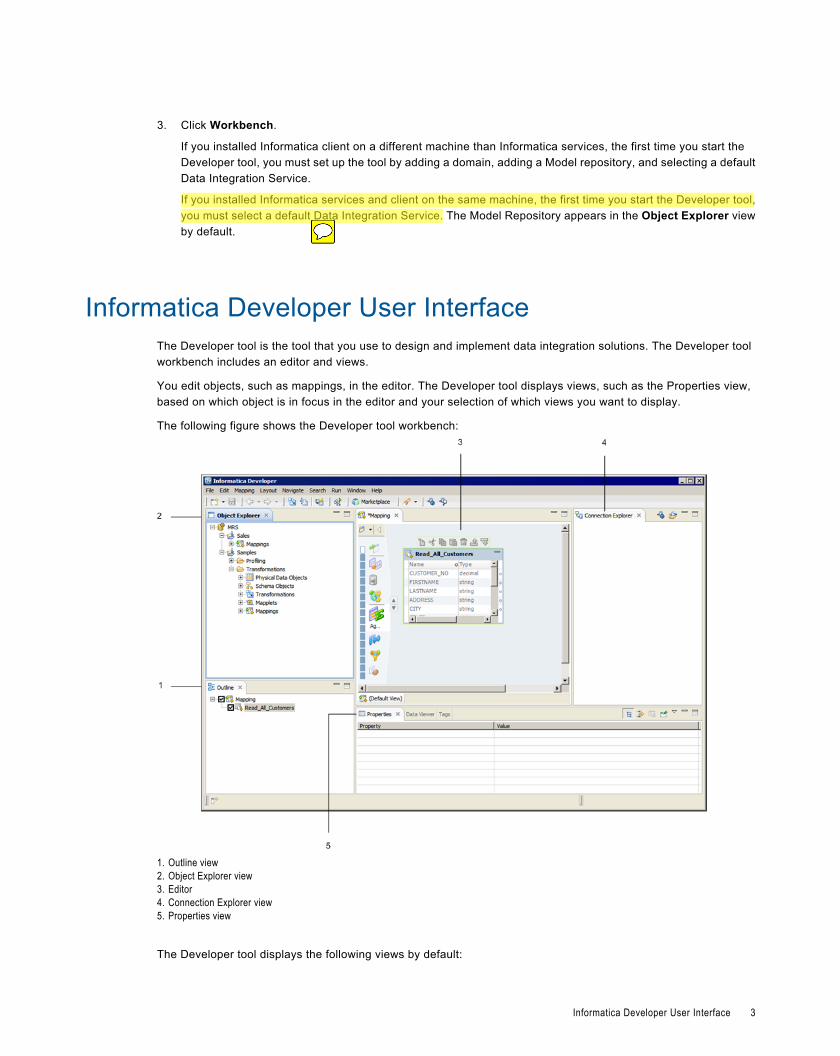
Informatica Developer User InterfaceThe Developer tool is the tool that you use to design and implement data integration solutions. The Developer toolworkbench includes an editor and views.
You edit objects, such as mappings, in the editor. The Developer tool displays views, such as the Properties view,based on which object is in focus in the editor and your selection of which views you want to display.
The following figure shows the Developer tool workbench:
1. Outline view2. Object Explorer view3. Editor4. Connection Explorer view5. Properties view
The Developer tool displays the following views by default:
Informatica Developer User Interface 3
Object Explorer view
Displays projects, folders, and the objects within the projects and folders. Appears in the top left area of theDeveloper tool.
Connection Explorer view
Displays connections to relational databases. Appears in the top right area of the Developer tool.
Outline view
Displays objects that are dependent on an object selected in the Object Explorer view. Appears in the bottom leftarea of the Developer tool.
Properties view
Displays the properties for an object that is in focus in the editor. Appears in the bottom area of the Developertool.
You can hide views and move views to another location in the Developer tool workbench. Click Window > Show Viewto select the views you want to display.
The Developer tool workbench also displays the following views:Cheat Sheets view
Displays the cheat sheet that you open. To open a cheat sheet, click Help > Cheat Sheets and select a cheatsheet.
Help view
Displays context-sensitive online help.
Progress view
Displays the progress of operations in the Developer tool, such as a mapping run.
Search view
Displays the search results. You can also launch the search options dialog box.
Tags view
Displays tags that define an object in the Model repository based on business usage.
Validation Log view
Displays object validation errors.
Informatica Developer Welcome PageThe first time you open the Developer tool, the Welcome page appears. Use the Welcome page to learn more aboutthe Developer tool, set up the Developer tool, and to start working in the Developer tool.
The Welcome page displays the following options:
Overview
Click the Overview button to get an overview of PowerCenter Express and a cheat sheet that includes the firststeps to begin using PowerCenter Express.
Tutorials
Click the Tutorials button to see cheat sheets for data integration tasks.
Web Resources
Click the Web Resources button for a links to Informatica resources that you can access on the web. Webresources include product documentation, how-to articles, and video tutorials.
4 Chapter 1: Informatica Developer
Click Help > Welcome to access the welcome page after you close it.
Cheat SheetsThe Developer tool includes cheat sheets as part of the online help. A cheat sheet is a step-by-step guide that helpsyou complete one or more tasks in the Developer tool.
When you follow a cheat sheet, you complete the tasks and see the results. For example, you can complete a cheatsheet to import and preview a physical data object.
To access cheat sheets, click Help > Cheat Sheets.
Informatica PreferencesThe Preferences dialog box contains settings for the Developer tool and for the Eclipse platform.
Use the Informatica preferences to manage settings in the Developer tool. For example, use Informatica preferencesto manage configurations, connections, transformation settings, tags, or available Data Integration Services.
The Developer tool is built on the Eclipse platform. The Preferences dialog box also includes preferences to managesettings for the Eclipse platform. Informatica supports only the Informatica preferences.
To access Informatica preferences, click Window > Preferences. In the Preferences dialog box, selectInformatica.
Informatica MarketplaceThe Informatica Marketplace provides prebuilt solutions to augment, extend, or enhance your data integrationimplementation.
To access Informatica Marketplace, click the Marketplace button on the toolbar. The Developer tool opens aMarketplace tab in the editor.
You must register as a user before you can log in to the Marketplace for the first time.
After you log in, you can view links to prebuilt solutions in the editor. You can search for a solution in the Marketplacesearch box and view the search results to find the solution. A solution might contain mappings, mapping objects,profiles, or workflows that you can import into the Model repository for use in the Developer tool.
To import a Marketplace solution, click the Import button next to a Marketplace solution and follow the steps to importthe solution into the Model repository. You must select a folder during the import process to copy the related sourcefiles and documentation for the solution.
After you import the solution into the Model repository, you can then run the mapping or edit it to fit the businessrequirement.
You can also post a solution to help other users in the Marketplace community.
Setting Up Informatica DeveloperTo set up the Developer tool, you might need to add the domain. You also need to select the Data Integration Service.The steps depend on whether you installed the Informatica services and client or the Informatica client.
To set up the Developer tool, complete the following tasks:
1. If you installed the Informatica client only, add the domain and Model repository.
Setting Up Informatica Developer 5
2. Select the default Data Integration Service.
After you set up the Developer tool, you can create projects and folders in the Model repository to store you work.
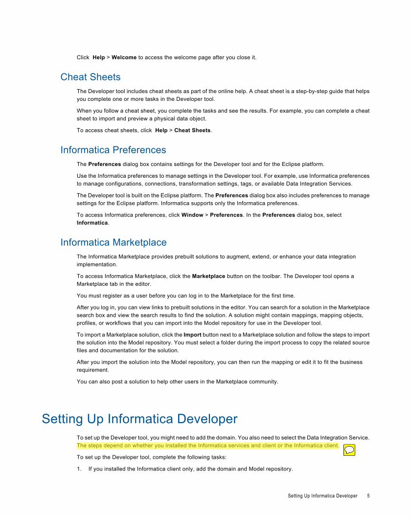
Step 1. Adding the Domain and RepositoryIf you installed the Informatica client on a different machine than Informatica services, you must add the domain andModel repository the first time you set up the Developer tool.
1. From the Developer tool menu, click File > Connect to Repository.
The Connect to Repository dialog box appears.
2. Click Configure Domains.
6 Chapter 1: Informatica Developer
The Preferences dialog box appears.
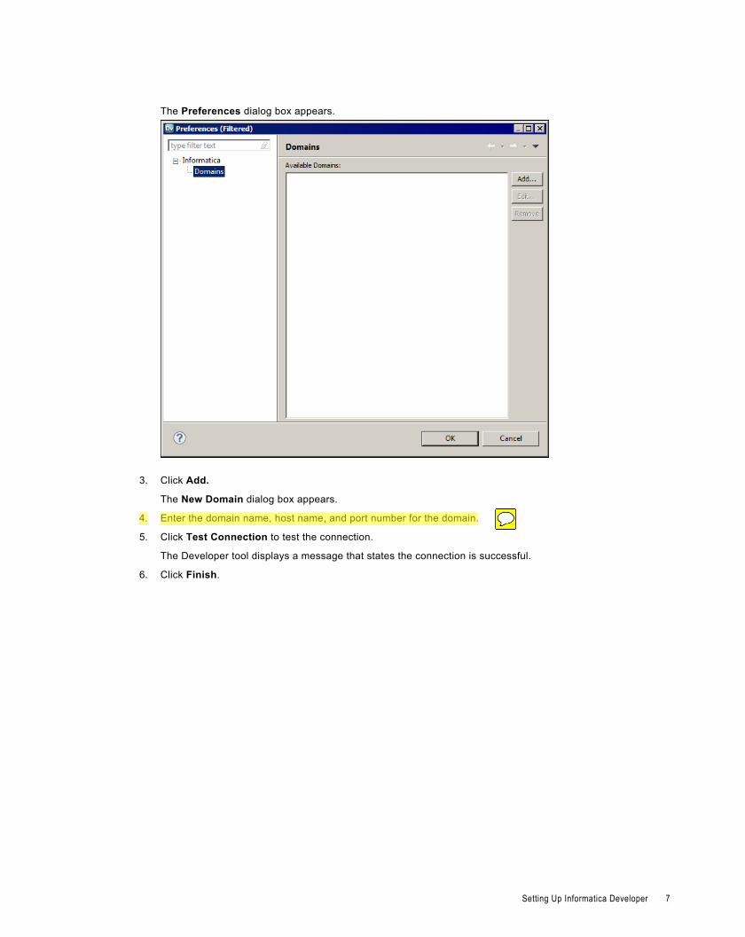
3. Click Add.
The New Domain dialog box appears.
4. Enter the domain name, host name, and port number for the domain.
5. Click Test Connection to test the connection.
The Developer tool displays a message that states the connection is successful.
6. Click Finish.
Setting Up Informatica Developer 7
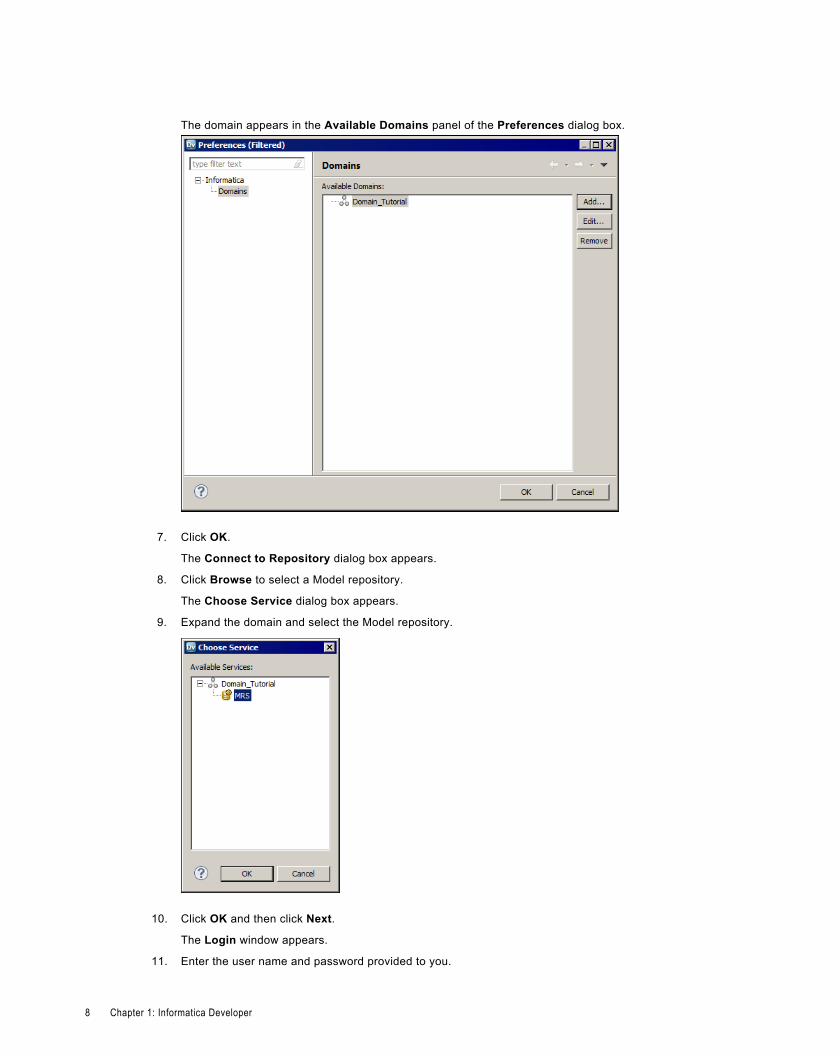
The domain appears in the Available Domains panel of the Preferences dialog box.
7. Click OK.
The Connect to Repository dialog box appears.
8. Click Browse to select a Model repository.
The Choose Service dialog box appears.
9. Expand the domain and select the Model repository.
10. Click OK and then click Next.
The Login window appears.
11. Enter the user name and password provided to you.
8 Chapter 1: Informatica Developer
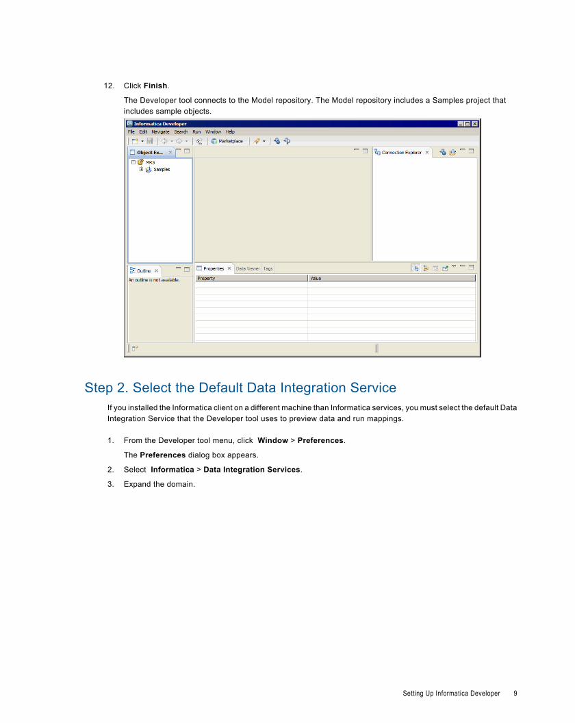
12. Click Finish.
The Developer tool connects to the Model repository. The Model repository includes a Samples project thatincludes sample objects.
Step 2. Select the Default Data Integration ServiceIf you installed the Informatica client on a different machine than Informatica services, you must select the default DataIntegration Service that the Developer tool uses to preview data and run mappings.
1. From the Developer tool menu, click Window > Preferences.
The Preferences dialog box appears.
2. Select Informatica > Data Integration Services.
3. Expand the domain.
Setting Up Informatica Developer 9
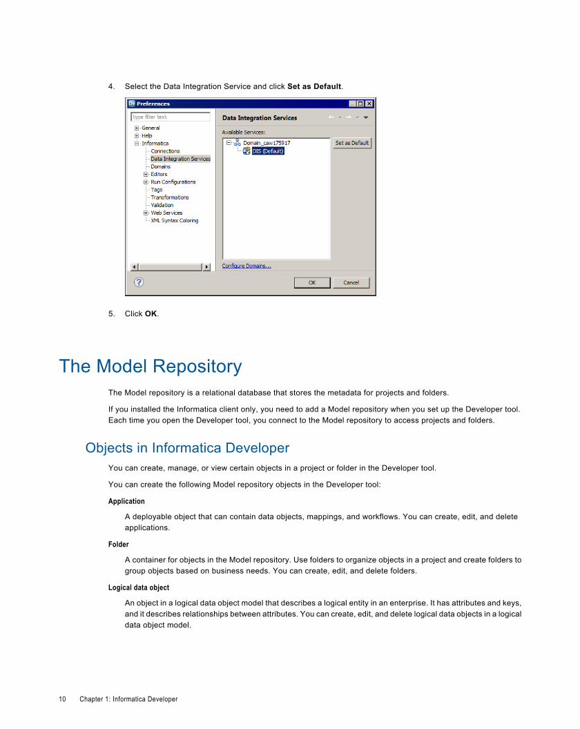
4. Select the Data Integration Service and click Set as Default.
5. Click OK.
The Model RepositoryThe Model repository is a relational database that stores the metadata for projects and folders.
If you installed the Informatica client only, you need to add a Model repository when you set up the Developer tool.Each time you open the Developer tool, you connect to the Model repository to access projects and folders.
Objects in Informatica DeveloperYou can create, manage, or view certain objects in a project or folder in the Developer tool.
You can create the following Model repository objects in the Developer tool:
Application
A deployable object that can contain data objects, mappings, and workflows. You can create, edit, and deleteapplications.
Folder
A container for objects in the Model repository. Use folders to organize objects in a project and create folders togroup objects based on business needs. You can create, edit, and delete folders.
Logical data object
An object in a logical data object model that describes a logical entity in an enterprise. It has attributes and keys,and it describes relationships between attributes. You can create, edit, and delete logical data objects in a logicaldata object model.
10 Chapter 1: Informatica Developer
Logical data object mapping
A mapping that links a logical data object to one or more physical data objects. It can include transformation logic.You can create, edit, and delete logical data object mappings for a logical data object.
Logical data object model
A data model that contains logical data objects and defines relationships between them. You can create, edit, anddelete logical data object models.
Mapping
A set of inputs and outputs linked by transformation objects that define the rules for data transformation. You cancreate, edit, and delete mappings.
Mapplet
A reusable object that contains a set of transformations that you can use in multiple mappings or validate as arule. You can create, edit, and delete mapplets.
Physical data object
A physical representation of data that is used to read from, look up, or write to resources. You can create, edit,and delete physical data objects.
Profile
An object that contains rules to discover patterns in source data. Run a profile to evaluate the data structure andverify that data columns contain the type of information that you expect. You can create, edit, and deleteprofiles.
Rule
Business logic that defines conditions applied to source data when you run a profile. It is a midstream mappletthat you use in a profile. You can create, edit, and delete rules.
Transformation
A repository object in a mapping that generates, modifies, or passes data. Each transformation performs adifferent function. You can create, edit, and delete transformations.
Workflow
A graphical representation of a set of events, tasks, and decisions that define a business process. You cancreate, edit, and delete workflows.
Object PropertiesYou can view the properties of a project, folder, or any other object in the Model repository.
The General view of the Properties dialog box shows the object properties. Object properties include the name,description, and location of the object in the repository. Object properties also include the user who created and lastupdated the object and the time the event occurred.
To access the object properties, select the object in the Object Explorer view and click File > Properties.
Connecting to a Model RepositoryEach time you open the Developer tool, you connect to a Model repository to access projects and folders. When youconnect to a Model repository, you enter connection information to access the domain that includes the ModelRepository Service that manages the Model repository.
The Model Repository 11
1. In the Object Explorer view, right-click a Model repository and click Connect.
The Connect to Repository dialog box appears.
2. Enter the domain user name and password.
3. Click OK.
The Developer tool connects to the Model repository. The Developer tool displays the projects in therepository.
ProjectsA project is the top-level container that you use to store folders and objects in the Developer tool.
Use projects to organize and manage the objects that you want to use for data integration solutions.
You manage and view projects in the Object Explorer view. When you create a project, the Developer tool stores theproject in the Model repository.
The following table describes the tasks that you can perform on a project:
Task Description
Manage projects Manage project contents. You can create, duplicate, rename, and delete a project. You can view projectcontents.
Filter projects Filter the list of projects that appear in the Object Explorer view.
Manage folders Organize project contents in folders. You can create, duplicate, rename, move, and rename folders withinprojects.
Manage objects View object contents, duplicate, rename, move, and delete objects in a project or in a folder within aproject.
Search projects Search for folders or objects in projects. You can view search results and select an object from the results toview its contents.
Assign permissions Select the users and groups that can view and edit objects in the project. Specify which users and groups canassign permissions to other users and groups.
Creating a ProjectCreate a project to store objects and folders.
1. Select a Model Repository Service in the Object Explorer view.
2. Click File > New > Project.
The New Project dialog box appears.
3. Enter a name for the project.
4. Click Next.
The Project Permissions page of the New Project dialog box appears.
5. Optionally, select a user or group and assign permissions.
12 Chapter 1: Informatica Developer
6. Click Finish.
The project appears under the Model Repository Service in the Object Explorer view.
Filter ProjectsYou can filter the list of projects that appear in the Object Explorer view. You might want to filter projects if you haveaccess to a large number of projects but need to manage only some of them.
The Developer tool retains the list of projects that you filter the next time that you connect to the repository.
You can filter projects at the following times:
Before you connect to the repository
When you filter projects before you connect to the repository, you can decrease the amount of time that theDeveloper tool takes to connect to the repository.
Select File > Connect to Repository. After you select the repository and enter your user name and password,click Next. The Open Project dialog box displays all projects to which you have access. Select the projects thatyou want to open in the repository and then click Finish.
After you connect to the repository
If you are connected to the repository, click File > Close Projects to filter projects out of the Object Explorerview. The Close Project dialog box displays all projects that are currently open in the Object Explorer view.Select the projects that you want to filter out and then click Finish.
To open projects that you filtered, click File > Open Projects.
Project PermissionsAssign project permissions to users or groups. Project permissions determine whether a user or group can viewobjects, edit objects, or assign permissions to others.
Depending on the type of PowerCenter Express license, you can assign the following permissions:
Read
The user or group can open, preview, export, validate, and deploy all objects in the project. The user or group canalso view project details.
Write
The user or group has read permission on all objects in the project. Additionally, the user or group can edit allobjects in the project, edit project details, delete all objects in the project, and delete the project.
Grant
The user or group has read permission on all objects in the project. Additionally, the user or group can assignpermissions to other users or groups.
Users assigned the Administrator role for a Model Repository Service inherit all permissions on all projects in theModel Repository Service. Users assigned to a group inherit the group permissions.
Project Permissions 13
Permissions for External ObjectsPermissions apply to objects within a project. The Developer tool does not extend permissions to dependent objectswhen the dependent objects exist in other projects.
Dependent objects are objects that are used by other objects. For example, you create a mapplet that contains anonreusable Expression transformation. The mapplet is the parent object. The Expression transformation is adependent object of the mapplet.
The Developer tool creates instances of objects when you use reusable objects within a parent object. For example,you create a mapping with a reusable Lookup transformation. The mapping is the parent object. It contains aninstance of the Lookup transformation.
An object can contain instances of dependent objects that exist in other projects. To view dependent object instancesfrom other projects, you must have read permission on the other projects. To edit dependent object instances fromother projects, you must have write permission on the parent object project and read permission on the otherprojects.
Permissions for Dependent Object InstancesYou might need to access an object that contains dependent object instances from another project. If you do not haveread permission on the other project, the Developer tool gives you different options based on how you access theparent object.
When you try to access a parent object that contains dependent object instances that you cannot view, the Developertool displays a warning message. If you continue the operation, the Developer tool produces results that vary byoperation type.
The following table lists the results of the operations that you can perform on the parent object:
Operation Result
Open the parent object. The Developer tool prompts you to determine how to open the parent object:- Open a Copy. The Developer tool creates a copy of the parent object. The copy does not
contain the dependent object instances that you cannot view.- Open. The Developer tool opens the object, but it removes the dependent object instances
that you cannot view. If you save the parent object, the Developer tool removes thedependent object instances from the parent object. The Developer tool does not removethe dependent objects from the repository.
- Cancel. The Developer tool does not open the parent object.
Export the parent object to an XMLfile for use in the Developer tool.
The Developer tool creates the export file without the dependent object instances.
Export the parent object toPowerCenter.
You cannot export the parent object.
Validate the parent object. The Developer tool validates the parent object as if the dependent objects were not part of theparent object.
Deploy the parent object. You cannot deploy the parent object.
Copy and paste the parent object. The Developer tool creates the new object without the dependent object instances.
Security DetailsWhen you access an object that contains dependent object instances that you cannot view, the Developer tooldisplays a warning message. The warning message allows you to view details about the dependent objects.
14 Chapter 1: Informatica Developer
To view details about the dependent objects, click the Details button in the warning message. If you have the ShowSecurity Details Model Repository Service privilege, the Developer tool lists the projects that contain the objects thatyou cannot view. If you do not have the Show Security Details privilege, the Developer tool indicates that you that youdo not have sufficient privileges to view the project names.
Parent Object AccessIf you create parent objects that use dependent object instances from other projects, users might not be able to editthe parent objects. If you want users to be able to edit the parent object and preserve the parent object functionality,you can create instances of the dependent objects in a mapplet.
For example, you create a mapping that contains a reusable Lookup transformation from another project. You wantthe users of your project to be able to edit the mapping, but not the Lookup transformation.
If you place the Lookup transformation in the mapping, users that do not have read permission on the other project geta warning message when they open the mapping. They can open a copy of the mapping or open the mapping, but theDeveloper tool removes the Lookup transformation instance.
To allow users to edit the mapping, perform the following tasks:
1. Create a mapplet in your project. Add an Input transformation, the reusable Lookup transformation, and anOutput transformation to the mapplet.
2. Edit the mapping, and replace the Lookup transformation with the mapplet.
3. Save the mapping.
When users of your project open the mapping, they see the mapplet instead of the Lookup transformation. The userscan edit any part of the mapping except the mapplet.
If users export the mapping, the Developer tool does not include the Lookup transformation in the export file.
Assigning PermissionsYou can add users and groups to a project and assign permissions for the users and groups. Assign permissions todetermine the tasks that users can complete on objects in the project.
The ability to assign permissions is dependent on the type of PowerCenter Express license.
1. Select a project in the Object Explorer view.
2. Click File > Properties.
The Properties window appears.
3. Select Permissions.
4. Click Add to add a user and assign permissions for the user.
The Domain Users and Groups dialog box appears.
5. To filter the list of users and groups, enter a name or string.
Optionally, use the wildcard characters in the filter.
6. To filter by security domain, click the Filter by Security Domains button.
7. Select Native to show users and groups in the native security domain. Or, select All to show all users andgroups.
8. Select a user or group, and click OK.
The user or group appears in the Project Permissions page of the New Project dialog box.
9. Select read, write, or grant permission for the user or group.
10. Click OK.
Project Permissions 15
FoldersUse folders to organize objects in a project. Create folders to group objects based on business needs. For example,you can create a folder to group objects for a particular task in a project. You can create a folder in a project or inanother folder.
Folders appear within projects in the Object Explorer view. A folder can contain other folders, data objects, andobject types.
You can perform the following tasks on a folder:
¨ Create a folder.
¨ View a folder.
¨ Rename a folder.
¨ Duplicate a folder.
¨ Move a folder.
¨ Delete a folder.
Creating a FolderCreate a folder to store related objects in a project. You must create the folder in a project or another folder.
1. In the Object Explorer view, select the project or folder where you want to create a folder.
2. Click File > New > Folder.
The New Folder dialog box appears.
3. Enter a name for the folder.
4. Click Finish.
The folder appears under the project or parent folder.
SearchYou can search for objects and object properties in the Developer tool.
You can create a search query and then filter the search results. You can view search results and select an object fromthe results to view its contents. Search results appear on the Search view. The search cannot display results if morethan 2048 objects are found. If search fails because the results contain more than 2048 objects, change the searchoptions so that fewer objects match the search criteria.
You can use the following search options:
Search Option Description
Containing text Object or property that you want to search for. Enter an exact string or use a wildcard. Not casesensitive.
Name patterns One or more objects that contain the name pattern. Enter an exact string or use a wildcard. Not casesensitive.
16 Chapter 1: Informatica Developer
Search Option Description
Search for One or more object types to search for.
Scope Search the workspace or an object that you selected.
The Model Repository Service uses a search engine to index the metadata in the Model repository. To correctly indexthe metadata, the search engine uses a search analyzer appropriate for the language of the metadata that you areindexing. The Developer tool uses the search engine to perform searches on objects contained in projects in theModel repository. You must save an object before you can search on it.
Searching for Objects and PropertiesSearch for objects and properties in the Model repository.
1. Click Search > Search.
The Search dialog box appears.
2. Enter the object or property you want to search for. Optionally, include wildcard characters.
3. If you want to search for a property in an object, optionally enter one or more name patterns separated by acomma.
4. Optionally, choose the object types you want to search for.
5. Choose to search the workspace or the object you selected.
6. Click Search.
The search results appear in the Search view.
7. In the Search view, double-click an object to open it in the editor.
Workspace EditorUse the editor to view and edit Model repository objects.
You can configure the following arrangement, layout, and navigation options in the editor:
Align All to Grid
Arranges objects in the editor based on data flow and aligns them to a grid. Objects retain their original size. Youcan use this option in a mapping or workflow editor. Open the Layout menu to select this option.
Arrange All
Aligns the objects in the editor and retains their original order and size. Open the Layout menu to select thisoption.
Arrange All Iconic
Converts the objects to icons and aligns the icons in the editor. You can use this option in a mapping or mappleteditor. Open the Layout menu to select this option.
Iconized View
Reduces objects to named icons. You can view iconized objects in a mapping or mapplet editor.
Workspace Editor 17
Maximize Active View or Editor
Expands the active window or editor to fill the screen. Click Window > Navigation to select this option.
Minimize Active View or Editor
Hides the active window or editor. Click Window > Navigation to select this option.
Normal View
Displays the information in each object in columns. The Developer tool displays objects in the normal view bydefault.
Reset Perspective
Restores all default views and editors. Open the Window menu to select this option.
Resize
After you resize an object, aligns objects in the editor and retains their current order and size. You can use thisoption in a mapping or mapplet editor. Hold the Shift key while resizing an object to use this option.
Find in EditorUse the editor to find objects, ports, groups, expressions, and attributes that are open in the editor. You can findobjects in any mapping, mapplet, logical data object model, or workflow editor.The Developer tool highlights theobjects within the open editor.
When you find objects, the Developer tool finds objects that are open in the editor. The objects do not need to be in theModel repository.
To display the find fields below the editor, select Edit > Find/Replace. To find an object, specify a search string andthe types of objects to find. The types of objects that you can find varies by editor. If you do not specify any type ofobject, the Developer tool finds the search string in transformations.
When you search for ports, columns, or attributes, you can also select the datatype. For example, you can find integeror bigint ports with names that contain the string "_ID."
The following table lists the types of objects that you can find in each editor:
Editor Object types
Mapping Mapping objects, expressions, groups, and ports
Mapplet Mapplet objects, expressions, groups, and ports
Logical data object model Logical data objects and attributes
Physical data object read or write mapping Mapping objects and columns
Workflow Workflow objects
When the Developer tool finds the search string, it displays the object locations. It also highlights the object in whichthe search string occurs. If the search string occurs in an iconized transformation in the mapping editor, the Developertool highlights the iconized transformation.
You can select the following options to navigate the results of a find:
¨ Next Match. Finds the next occurrence of the search string.
¨ Previous Match. Finds the previous occurrence of the search string.
18 Chapter 1: Informatica Developer
¨ Highlight All. Highlights all occurrences of the search string.
¨ Expand Iconized Transformations. Expands all iconized transformations in which the search string occurs.
Validation PreferencesYou can limit the number of error messages that appear in the Validation Log view. You can also group errormessages by object or object type in the Validation Log view.
Grouping Error MessagesGroup error messages in the Validation Log view to organize messages by object or object type. Otherwise,messages appear alphabetically.
To group error messages in the Validation Log view, select Menu > Group By and then select Object or ObjectType.
To remove error message groups, select Menu > Group By > None. Error messages appear ungrouped, listedalphabetically in the Validation Log view.
Limiting Error MessagesYou can limit the number of error messages that appear in the Validation Log view. The limit determines how manymessages appear in a group or the total number of messages that appear in the Validation Log view. Error messagesare listed alphabetically and get deleted from bottom to top when a limit is applied.
1. Click Window > Preferences.
The Preferences dialog box appears.
2. Select Informatica > Validation.
3. Optionally, set the error limit and configure the number of items that appear.
Default is 100.
4. To restore the default values, click Restore Defaults.
5. Click Apply.
6. Click OK.
CopyYou can copy objects within a project or to a different project. You can also copy objects to folders in the same projector to folders in a different project.
You can copy the following objects to another project or folder or save copies of the objects with different names
¨ Application
¨ Logical data object model
¨ Mapping
Validation Preferences 19
¨ Mapplet
¨ Physical data object
¨ Profile
¨ Reusable transformation
¨ Rule
¨ Workflow
Use the following guidelines when you copy objects:
¨ You can copy segments of mappings, mapplets, and rules.
¨ You can copy a folder to another project.
¨ You can paste an object multiple times after you copy it.
¨ If the project or folder contains an object with the same name, you can rename or replace the object.
Copying an ObjectCopy an object to make it available in another project or folder.
1. Select an object in a project or folder.
2. Click Edit > Copy.
3. Select the project or folder that you want to copy the object to.
4. Click Edit > Paste.
Saving a Copy of an ObjectSave a copy of an object to save the object with a different name.
1. Open an object in the editor.
2. Click File > Save a Copy As.
3. Enter a name for the copy of the object.
4. Click Browse to select the project or folder that you want to copy the object to.
5. Click Finish.
20 Chapter 1: Informatica Developer
C H A P T E R 2
ConnectionsThis chapter includes the following topics:
¨ Connections Overview, 21
¨ IBM DB2 Connection Properties, 23
¨ JDBC Connection Properties, 24
¨ Microsoft SQL Server Connection Properties, 24
¨ ODBC Connection Properties, 26
¨ Oracle Connection Properties, 26
¨ Web Services Connection Properties, 27
¨ Connection Explorer View, 29
¨ Creating Connections, 29
¨ Showing Connections, 30
¨ Editing a Connection, 31
¨ Copying a Connection, 31
¨ Deleting a Connection, 32
¨ Refreshing the Connections List, 32
Connections OverviewA connection is a repository object that defines a connection in the domain configuration repository.
Create a connection to import data objects, preview data, profile data, and run mappings. The Developer tool uses theconnection when you import a data object. The Data Integration Service uses the connection when you preview data,run mappings, or consume web services.
The Developer tool stores connections in the domain configuration repository. Any connection that you create in theDeveloper tool is available in the Administrator tool.
Create and manage connections using the Create Connection and Show Connections buttons.
21
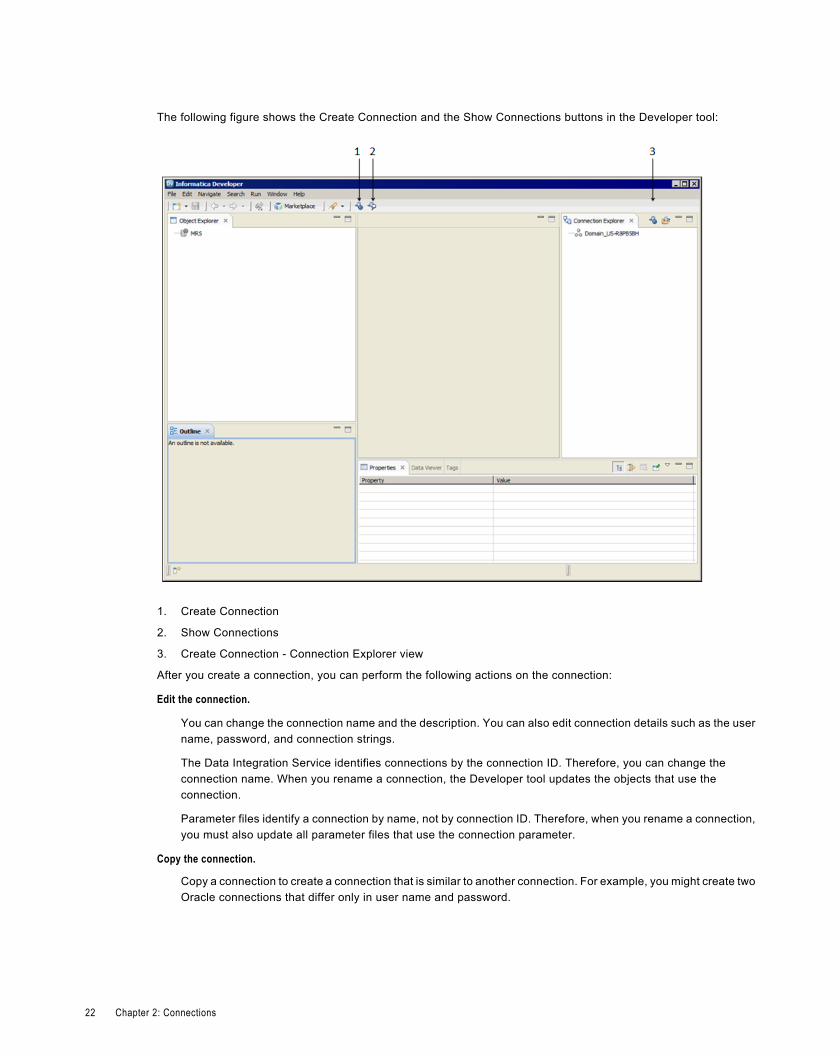
The following figure shows the Create Connection and the Show Connections buttons in the Developer tool:
1. Create Connection
2. Show Connections
3. Create Connection - Connection Explorer view
After you create a connection, you can perform the following actions on the connection:
Edit the connection.
You can change the connection name and the description. You can also edit connection details such as the username, password, and connection strings.
The Data Integration Service identifies connections by the connection ID. Therefore, you can change theconnection name. When you rename a connection, the Developer tool updates the objects that use theconnection.
Parameter files identify a connection by name, not by connection ID. Therefore, when you rename a connection,you must also update all parameter files that use the connection parameter.
Copy the connection.
Copy a connection to create a connection that is similar to another connection. For example, you might create twoOracle connections that differ only in user name and password.
22 Chapter 2: Connections
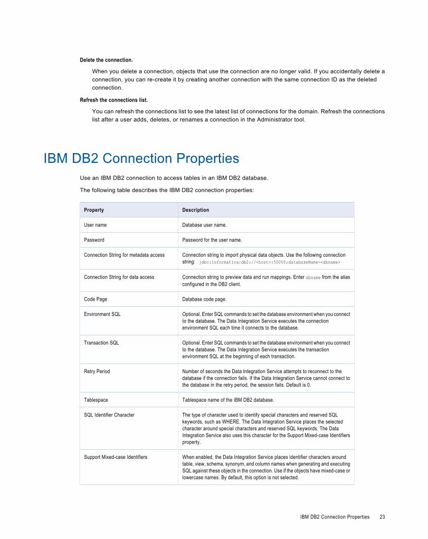
Delete the connection.
When you delete a connection, objects that use the connection are no longer valid. If you accidentally delete aconnection, you can re-create it by creating another connection with the same connection ID as the deletedconnection.
Refresh the connections list.
You can refresh the connections list to see the latest list of connections for the domain. Refresh the connectionslist after a user adds, deletes, or renames a connection in the Administrator tool.
IBM DB2 Connection PropertiesUse an IBM DB2 connection to access tables in an IBM DB2 database.
The following table describes the IBM DB2 connection properties:
Property Description
User name Database user name.
Password Password for the user name.
Connection String for metadata access Connection string to import physical data objects. Use the following connectionstring: jdbc:informatica:db2://<host>:50000;databaseName=<dbname>
Connection String for data access Connection string to preview data and run mappings. Enter dbname from the aliasconfigured in the DB2 client.
Code Page Database code page.
Environment SQL Optional. Enter SQL commands to set the database environment when you connectto the database. The Data Integration Service executes the connectionenvironment SQL each time it connects to the database.
Transaction SQL Optional. Enter SQL commands to set the database environment when you connectto the database. The Data Integration Service executes the transactionenvironment SQL at the beginning of each transaction.
Retry Period Number of seconds the Data Integration Service attempts to reconnect to thedatabase if the connection fails. If the Data Integration Service cannot connect tothe database in the retry period, the session fails. Default is 0.
Tablespace Tablespace name of the IBM DB2 database.
SQL Identifier Character The type of character used to identify special characters and reserved SQLkeywords, such as WHERE. The Data Integration Service places the selectedcharacter around special characters and reserved SQL keywords. The DataIntegration Service also uses this character for the Support Mixed-case Identifiersproperty.
Support Mixed-case Identifiers When enabled, the Data Integration Service places identifier characters aroundtable, view, schema, synonym, and column names when generating and executingSQL against these objects in the connection. Use if the objects have mixed-case orlowercase names. By default, this option is not selected.
IBM DB2 Connection Properties 23
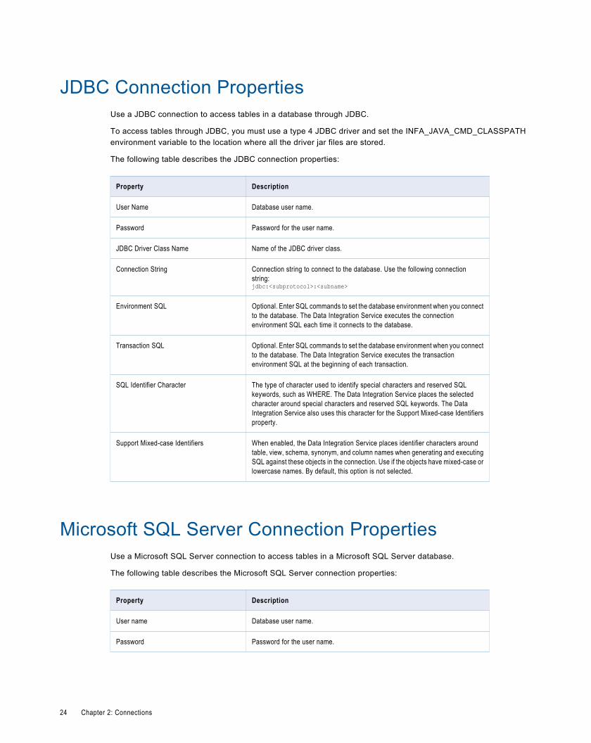
JDBC Connection PropertiesUse a JDBC connection to access tables in a database through JDBC.
To access tables through JDBC, you must use a type 4 JDBC driver and set the INFA_JAVA_CMD_CLASSPATHenvironment variable to the location where all the driver jar files are stored.
The following table describes the JDBC connection properties:
Property Description
User Name Database user name.
Password Password for the user name.
JDBC Driver Class Name Name of the JDBC driver class.
Connection String Connection string to connect to the database. Use the following connectionstring:jdbc:<subprotocol>:<subname>
Environment SQL Optional. Enter SQL commands to set the database environment when you connectto the database. The Data Integration Service executes the connectionenvironment SQL each time it connects to the database.
Transaction SQL Optional. Enter SQL commands to set the database environment when you connectto the database. The Data Integration Service executes the transactionenvironment SQL at the beginning of each transaction.
SQL Identifier Character The type of character used to identify special characters and reserved SQLkeywords, such as WHERE. The Data Integration Service places the selectedcharacter around special characters and reserved SQL keywords. The DataIntegration Service also uses this character for the Support Mixed-case Identifiersproperty.
Support Mixed-case Identifiers When enabled, the Data Integration Service places identifier characters aroundtable, view, schema, synonym, and column names when generating and executingSQL against these objects in the connection. Use if the objects have mixed-case orlowercase names. By default, this option is not selected.
Microsoft SQL Server Connection PropertiesUse a Microsoft SQL Server connection to access tables in a Microsoft SQL Server database.
The following table describes the Microsoft SQL Server connection properties:
Property Description
User name Database user name.
Password Password for the user name.
24 Chapter 2: Connections
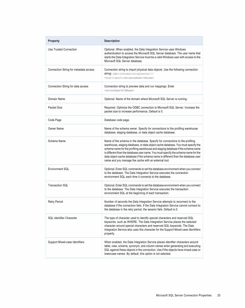
Property Description
Use Trusted Connection Optional. When enabled, the Data Integration Service uses Windowsauthentication to access the Microsoft SQL Server database. The user name thatstarts the Data Integration Service must be a valid Windows user with access to theMicrosoft SQL Server database.
Connection String for metadata access Connection string to import physical data objects. Use the following connectionstring: jdbc:informatica:sqlserver://<host>:<port>;databaseName=<dbname>
Connection String for data access Connection string to preview data and run mappings. Enter<ServerName>@<DBName>
Domain Name Optional. Name of the domain where Microsoft SQL Server is running.
Packet Size Required. Optimize the ODBC connection to Microsoft SQL Server. Increase thepacket size to increase performance. Default is 0.
Code Page Database code page.
Owner Name Name of the schema owner. Specify for connections to the profiling warehousedatabase, staging database, or data object cache database.
Schema Name Name of the schema in the database. Specify for connections to the profilingwarehouse, staging database, or data object cache database. You must specify theschema name for the profiling warehouse and staging database if the schema nameis different than the database user name. You must specify the schema name for thedata object cache database if the schema name is different than the database username and you manage the cache with an external tool.
Environment SQL Optional. Enter SQL commands to set the database environment when you connectto the database. The Data Integration Service executes the connectionenvironment SQL each time it connects to the database.
Transaction SQL Optional. Enter SQL commands to set the database environment when you connectto the database. The Data Integration Service executes the transactionenvironment SQL at the beginning of each transaction.
Retry Period Number of seconds the Data Integration Service attempts to reconnect to thedatabase if the connection fails. If the Data Integration Service cannot connect tothe database in the retry period, the session fails. Default is 0.
SQL Identifier Character The type of character used to identify special characters and reserved SQLkeywords, such as WHERE. The Data Integration Service places the selectedcharacter around special characters and reserved SQL keywords. The DataIntegration Service also uses this character for the Support Mixed-case Identifiersproperty.
Support Mixed-case Identifiers When enabled, the Data Integration Service places identifier characters aroundtable, view, schema, synonym, and column names when generating and executingSQL against these objects in the connection. Use if the objects have mixed-case orlowercase names. By default, this option is not selected.
Microsoft SQL Server Connection Properties 25
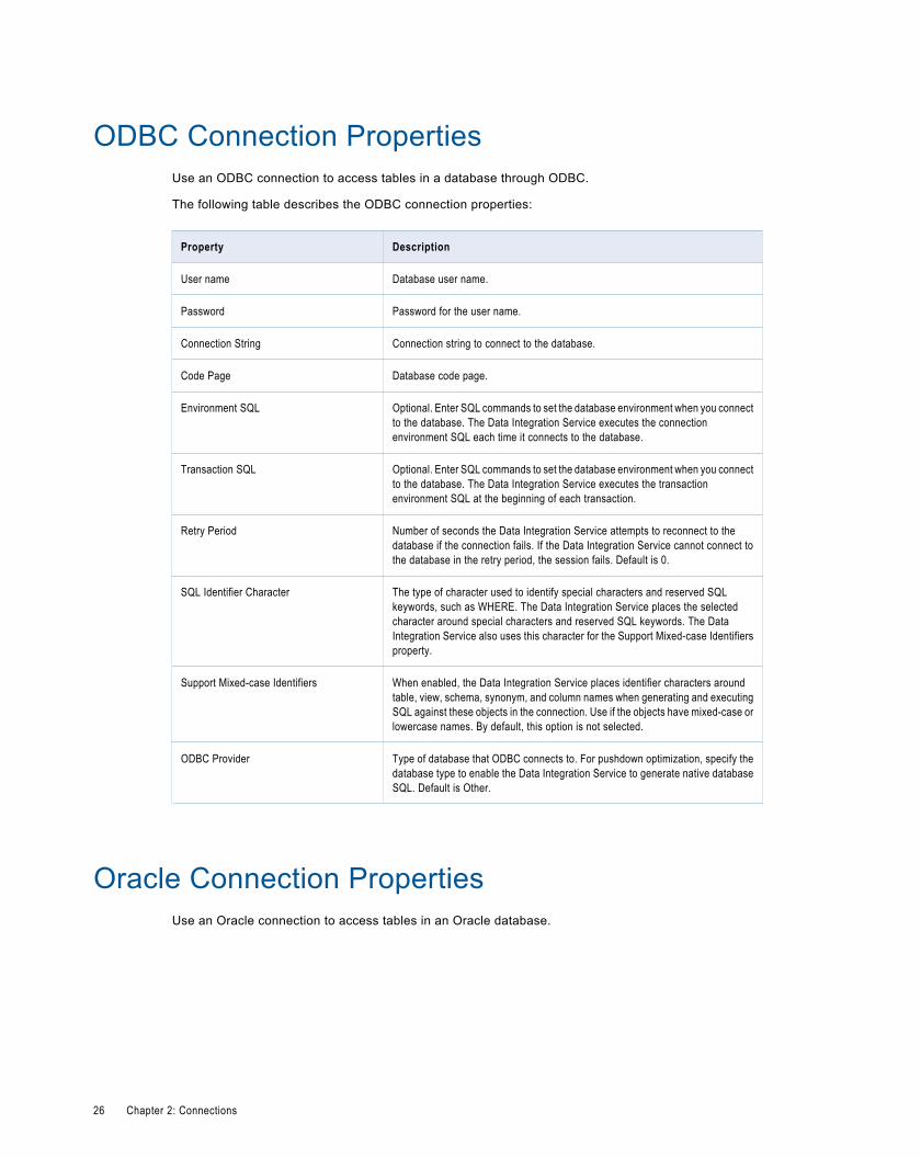
ODBC Connection PropertiesUse an ODBC connection to access tables in a database through ODBC.
The following table describes the ODBC connection properties:
Property Description
User name Database user name.
Password Password for the user name.
Connection String Connection string to connect to the database.
Code Page Database code page.
Environment SQL Optional. Enter SQL commands to set the database environment when you connectto the database. The Data Integration Service executes the connectionenvironment SQL each time it connects to the database.
Transaction SQL Optional. Enter SQL commands to set the database environment when you connectto the database. The Data Integration Service executes the transactionenvironment SQL at the beginning of each transaction.
Retry Period Number of seconds the Data Integration Service attempts to reconnect to thedatabase if the connection fails. If the Data Integration Service cannot connect tothe database in the retry period, the session fails. Default is 0.
SQL Identifier Character The type of character used to identify special characters and reserved SQLkeywords, such as WHERE. The Data Integration Service places the selectedcharacter around special characters and reserved SQL keywords. The DataIntegration Service also uses this character for the Support Mixed-case Identifiersproperty.
Support Mixed-case Identifiers When enabled, the Data Integration Service places identifier characters aroundtable, view, schema, synonym, and column names when generating and executingSQL against these objects in the connection. Use if the objects have mixed-case orlowercase names. By default, this option is not selected.
ODBC Provider Type of database that ODBC connects to. For pushdown optimization, specify thedatabase type to enable the Data Integration Service to generate native databaseSQL. Default is Other.
Oracle Connection PropertiesUse an Oracle connection to access tables in an Oracle database.
26 Chapter 2: Connections
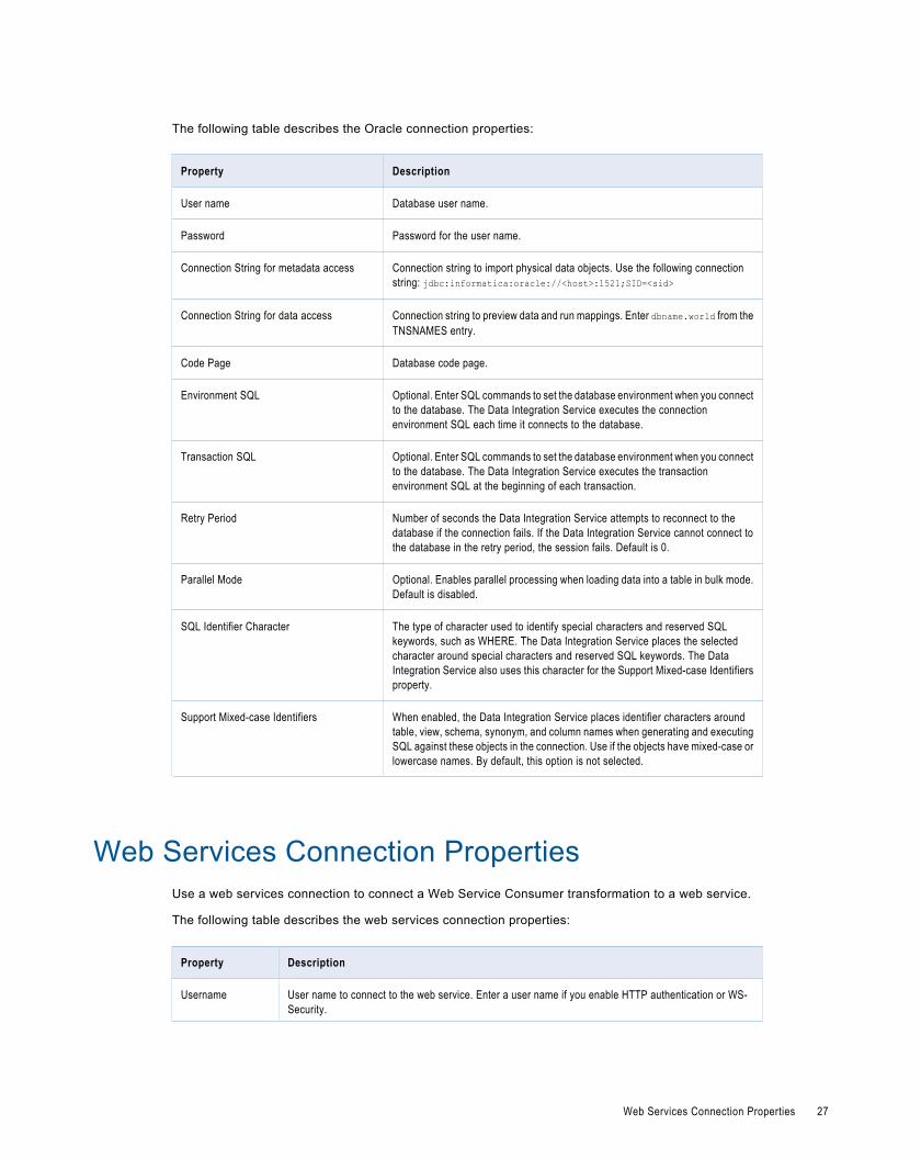
The following table describes the Oracle connection properties:
Property Description
User name Database user name.
Password Password for the user name.
Connection String for metadata access Connection string to import physical data objects. Use the following connectionstring: jdbc:informatica:oracle://<host>:1521;SID=<sid>
Connection String for data access Connection string to preview data and run mappings. Enter dbname.world from theTNSNAMES entry.
Code Page Database code page.
Environment SQL Optional. Enter SQL commands to set the database environment when you connectto the database. The Data Integration Service executes the connectionenvironment SQL each time it connects to the database.
Transaction SQL Optional. Enter SQL commands to set the database environment when you connectto the database. The Data Integration Service executes the transactionenvironment SQL at the beginning of each transaction.
Retry Period Number of seconds the Data Integration Service attempts to reconnect to thedatabase if the connection fails. If the Data Integration Service cannot connect tothe database in the retry period, the session fails. Default is 0.
Parallel Mode Optional. Enables parallel processing when loading data into a table in bulk mode.Default is disabled.
SQL Identifier Character The type of character used to identify special characters and reserved SQLkeywords, such as WHERE. The Data Integration Service places the selectedcharacter around special characters and reserved SQL keywords. The DataIntegration Service also uses this character for the Support Mixed-case Identifiersproperty.
Support Mixed-case Identifiers When enabled, the Data Integration Service places identifier characters aroundtable, view, schema, synonym, and column names when generating and executingSQL against these objects in the connection. Use if the objects have mixed-case orlowercase names. By default, this option is not selected.
Web Services Connection PropertiesUse a web services connection to connect a Web Service Consumer transformation to a web service.
The following table describes the web services connection properties:
Property Description
Username User name to connect to the web service. Enter a user name if you enable HTTP authentication or WS-Security.
Web Services Connection Properties 27
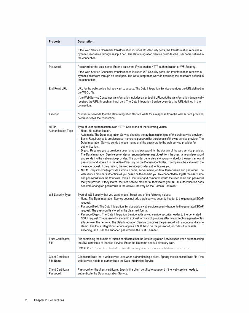
Property Description
If the Web Service Consumer transformation includes WS-Security ports, the transformation receives adynamic user name through an input port. The Data Integration Service overrides the user name defined inthe connection.
Password Password for the user name. Enter a password if you enable HTTP authentication or WS-Security.If the Web Service Consumer transformation includes WS-Security ports, the transformation receives adynamic password through an input port. The Data Integration Service overrides the password defined inthe connection.
End Point URL URL for the web service that you want to access. The Data Integration Service overrides the URL defined inthe WSDL file.If the Web Service Consumer transformation includes an endpoint URL port, the transformation dynamicallyreceives the URL through an input port. The Data Integration Service overrides the URL defined in theconnection.
Timeout Number of seconds that the Data Integration Service waits for a response from the web service providerbefore it closes the connection.
HTTPAuthentication Type
Type of user authentication over HTTP. Select one of the following values:- None. No authentication.- Automatic. The Data Integration Service chooses the authentication type of the web service provider.- Basic. Requires you to provide a user name and password for the domain of the web service provider. The
Data Integration Service sends the user name and the password to the web service provider forauthentication.
- Digest. Requires you to provide a user name and password for the domain of the web service provider.The Data Integration Service generates an encrypted message digest from the user name and passwordand sends it to the web service provider. The provider generates a temporary value for the user name andpassword and stores it in the Active Directory on the Domain Controller. It compares the value with themessage digest. If they match, the web service provider authenticates you.
- NTLM. Requires you to provide a domain name, server name, or default user name and password. Theweb service provider authenticates you based on the domain you are connected to. It gets the user nameand password from the Windows Domain Controller and compares it with the user name and passwordthat you provide. If they match, the web service provider authenticates you. NTLM authentication doesnot store encrypted passwords in the Active Directory on the Domain Controller.
WS Security Type Type of WS-Security that you want to use. Select one of the following values:- None. The Data Integration Service does not add a web service security header to the generated SOAP
request.- PasswordText. The Data Integration Service adds a web service security header to the generated SOAP
request. The password is stored in the clear text format.- PasswordDigest. The Data Integration Service adds a web service security header to the generated
SOAP request. The password is stored in a digest form which provides effective protection against replayattacks over the network. The Data Integration Service combines the password with a nonce and a timestamp. The Data Integration Service applies a SHA hash on the password, encodes it in base64encoding, and uses the encoded password in the SOAP header.
Trust CertificatesFile
File containing the bundle of trusted certificates that the Data Integration Service uses when authenticatingthe SSL certificate of the web service. Enter the file name and full directory path.Default is <Informatica installation directory>/services/shared/bin/ca-bundle.crt.
Client CertificateFile Name
Client certificate that a web service uses when authenticating a client. Specify the client certificate file if theweb service needs to authenticate the Data Integration Service.
Client CertificatePassword
Password for the client certificate. Specify the client certificate password if the web service needs toauthenticate the Data Integration Service.
28 Chapter 2: Connections
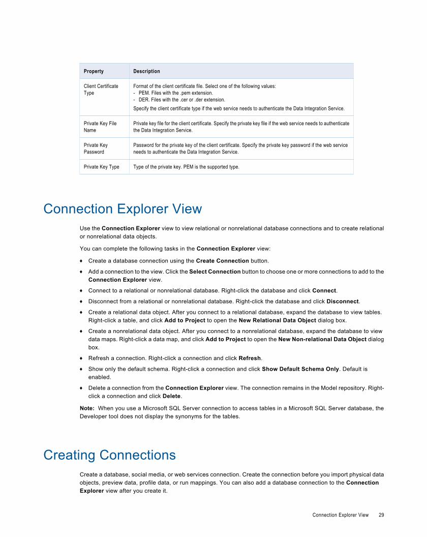
Property Description
Client CertificateType
Format of the client certificate file. Select one of the following values:- PEM. Files with the .pem extension.- DER. Files with the .cer or .der extension.Specify the client certificate type if the web service needs to authenticate the Data Integration Service.
Private Key FileName
Private key file for the client certificate. Specify the private key file if the web service needs to authenticatethe Data Integration Service.
Private KeyPassword
Password for the private key of the client certificate. Specify the private key password if the web serviceneeds to authenticate the Data Integration Service.
Private Key Type Type of the private key. PEM is the supported type.
Connection Explorer ViewUse the Connection Explorer view to view relational or nonrelational database connections and to create relationalor nonrelational data objects.
You can complete the following tasks in the Connection Explorer view:
¨ Create a database connection using the Create Connection button.
¨ Add a connection to the view. Click the Select Connection button to choose one or more connections to add to theConnection Explorer view.
¨ Connect to a relational or nonrelational database. Right-click the database and click Connect.
¨ Disconnect from a relational or nonrelational database. Right-click the database and click Disconnect.
¨ Create a relational data object. After you connect to a relational database, expand the database to view tables.Right-click a table, and click Add to Project to open the New Relational Data Object dialog box.
¨ Create a nonrelational data object. After you connect to a nonrelational database, expand the database to viewdata maps. Right-click a data map, and click Add to Project to open the New Non-relational Data Object dialogbox.
¨ Refresh a connection. Right-click a connection and click Refresh.
¨ Show only the default schema. Right-click a connection and click Show Default Schema Only. Default isenabled.
¨ Delete a connection from the Connection Explorer view. The connection remains in the Model repository. Right-click a connection and click Delete.
Note: When you use a Microsoft SQL Server connection to access tables in a Microsoft SQL Server database, theDeveloper tool does not display the synonyms for the tables.
Creating ConnectionsCreate a database, social media, or web services connection. Create the connection before you import physical dataobjects, preview data, profile data, or run mappings. You can also add a database connection to the ConnectionExplorer view after you create it.
Connection Explorer View 29
1. Click Create Connection button in the Developer tool bar.
The New <Connection Type> Connection dialog box appears.
2. Select the type of connection that you want to create:
¨ To select a database connection, select Databases.
¨ To select a social media connection, select Social Media.
¨ To select a web services connection, select Web Services Connections.
3. Enter the following information:
Property Description
Name Name of the connection. The name is not case sensitive and must be unique within the domain. Itcannot exceed 128 characters, contain spaces, or contain the following special characters:~ ` ! $ % ^ & * ( ) - + = { [ } ] | \ : ; " ' < , > . ? /
ID String that the Data Integration Service uses to identify the connection. The ID is not casesensitive. It must be 255 characters or less and must be unique in the domain. You cannot changethis property after you create the connection. Default value is the connection name.
Description Optional description for the connection.
Location Domain in which the connection exists.
Type Type of connection.
4. Click Next.
5. Configure the connection properties.
6. Click Test Connection to verify that you entered the connection properties correctly and that you canconnect.
7. Click Finish.
8. When you create a database connection, the Add Connection dialog box appears. You can choose to add theconnection to the Connection Explorer view.
The new connection appears in the Connection Explorer view.
Showing ConnectionsYou can see and manage available connections in the Informatica domain.
1. Click Show Connections in the Developer toolbar.
The Preferences dialog box appears.
2. Select the type of connection:
¨ To select a non-web services connection, select Informatica > Connections.
¨ To select a web services connection, select Informatica > Web Services > Connections.
3. Expand the domain in the Available Connections list to see available connections.
You can also add, edit, remove, copy, and refresh the connection list.
30 Chapter 2: Connections
Editing a ConnectionYou can edit the connection name, description, and connection properties.
1. Click Window > Preferences.
2. Select the type of connection that you want to edit:
¨ To select a non-web services connection, select Informatica > Connections.
¨ To select a web services connection, select Informatica > Web Services > Connections.
3. Expand the domain in the Available Connections list.
4. Select the connection in Available Connections, and click Edit.
The Edit Connection dialog box appears.
5. Optionally, edit the connection name and description.
Note: If you change a connection name, you must redeploy all applications that use the connection. You mustalso update all parameter files that use the connection parameter.
6. Click Next.
7. Optionally, edit the connection properties.
8. Click Test Connection to verify that you entered the connection properties correctly and that you can connect tothe database.
9. Click OK to close the Edit Connection dialog box.
10. Click OK to close the Preferences dialog box.
Copying a ConnectionYou can copy a connection within a domain or into another domain.
1. Click Window > Preferences.
2. Select the type of connection that you want to copy:
¨ To select a non-web services connection, select Informatica > Connections.
¨ To select a web services connection, select Informatica > Web Services > Connections.
3. Expand the domain in the Available Connections list.
4. Select the connection in Available Connections, and click Copy.
The Copy Connection dialog box appears.
5. Enter the connection name and ID, and select the domain.
The name and ID must be unique in the domain.
6. Click OK to close the Copy Connection dialog box.
7. Click OK to close the Preferences dialog box.
Editing a Connection 31
Deleting a ConnectionWhen you delete a connection through the Preferences dialog box, the Developer tool removes the connection fromthe Model repository.
1. Click Window > Preferences.
2. Select the type of connection that you want to delete:
¨ To select a non-web services connection, select Informatica > Connections.
¨ To select a web services connection, select Informatica > Web Services > Connections.
3. Expand the domain in the Available Connections list.
4. Select the connection in Available Connections, and click Remove.
5. Click OK to close the Preferences dialog box.
Refreshing the Connections ListRefresh the connections list to see the latest list of connections in the domain.
1. Click Window > Preferences.
2. Select the type of connection that you want to refresh:
¨ To select a non-web services connection, select Informatica > Connections.
¨ To select a web services connection, select Informatica > Web Services > Connections.
3. Select the domain in the Available Connections list.
4. Click Refresh.
5. Expand the domain in the Available Connections list to see the latest list of connections.
6. Click OK to close the Preferences dialog box.
32 Chapter 2: Connections
C H A P T E R 3
Physical Data ObjectsThis chapter includes the following topics:
¨ Physical Data Objects Overview, 33
¨ Relational Data Objects, 34
¨ Customized Data Objects, 36
¨ Custom Queries, 41
¨ Flat File Data Objects, 51
¨ WSDL Data Object , 62
¨ Synchronization, 65
¨ Troubleshooting Physical Data Objects, 65
Physical Data Objects OverviewA physical data object is the physical representation of data that is used to read from, look up, or write toresources.
A physical data object can be one of the following types:
Relational data object
A physical data object that uses a relational table, view, or synonym as a source. For example, you can create arelational data object from an Oracle view.
Depending on the object type, you can add a relational data object to a mapping or mapplet as a source, a target,or a Lookup transformation.
Customized data object
A physical data object that uses one or multiple related relational resources or relational data objects as sources.Relational resources include tables, views, and synonyms. For example, you can create a customized data objectfrom two Microsoft SQL Server tables that have a primary key-foreign key relationship.
Create a customized data object if you want to perform operations such as joining data, filtering rows, sortingports, or running custom queries in a reusable data object.
Flat file data object
A physical data object that uses a flat file as a source. You can create a flat file data object from a delimited orfixed-width flat file.
33
WSDL data object
A physical data object that uses a WSDL file as a source.
If the data object source changes, you can synchronize the physical data object. When you synchronize a physicaldata object, the Developer tool reimports the object metadata.
You can create any physical data object in a project or folder. Physical data objects in projects and folders arereusable objects. You can use them in any type of mapping, mapplet, or profile, but you cannot change the data objectwithin the mapping, mapplet, or profile. To update the physical data object, you must edit the object within the projector folder.
You can include a physical data object in a mapping, mapplet, or profile. You can add a physical data object to amapping or mapplet as a read, write, or lookup transformation. You can add a physical data object to a logical dataobject mapping to map logical data objects.
Relational Data ObjectsImport a relational data object to include in a mapping, mapplet, or profile. A relational data object is a physical dataobject that uses a relational table, view, or synonym as a source.
You can create primary key-foreign key relationships between relational data objects. You can create keyrelationships between relational data objects whether or not the relationships exist in the source database.
You can include relational data objects in mappings and mapplets. You can a add relational data object to a mappingor mapplet as a read, write, or lookup transformation. You can add multiple relational data objects to a mapping ormapplet as sources. When you add multiple relational data objects at the same time, the Developer tool prompts youto add the objects in either of the following ways:
¨ As related data objects. The Developer tool creates one read transformation. The read transformation has thesame capabilities as a customized data object.
¨ As independent data objects. The Developer tool creates one read transformation for each relational data object.The read transformations have the same capabilities as relational data objects.
You can import the following types of relational data object:
¨ DB2 for z/OS
¨ IBM DB2
¨ JDBC
¨ Microsoft SQL Server
¨ ODBC
¨ Oracle
Key RelationshipsYou can create key relationships between relational data objects. Key relationships allow you to join relational dataobjects when you use them as sources in a customized data object or as read transformations in a mapping ormapplet.
When you import relational data objects, the Developer tool retains the primary key information defined in thedatabase. When you import related relational data objects at the same time, the Developer tool also retains foreignkeys and key relationships. However, if you import related relational data objects separately, you must re-create thekey relationships after you import the objects.
34 Chapter 3: Physical Data Objects
To create key relationships between relational data objects, first create a primary key in the referenced object. Thencreate the relationship in the relational data object that contains the foreign key.
The key relationships that you create exist in the relational data object metadata. You do not need to alter the sourcerelational resources.
Creating Keys in a Relational Data ObjectCreate key columns to identify each row in a relational data object. You can create one primary key in each relationaldata object.
1. Open the relational data object.
2. Select the Keys view.
3. Click Add.
The New Key dialog box appears.
4. Enter a key name.
5. If the key is a primary key, select Primary Key.
6. Select the key columns.
7. Click OK.
8. Save the relational data object.
Creating Relationships between Relational Data ObjectsYou can create key relationships between relational data objects. You cannot create key relationships between arelational data object and a customized data object.
The relational data object that you reference must have a primary key.
1. Open the relational data object where you want to create a foreign key.
2. Select the Relationships view.
3. Click Add.
The New Relationship dialog box appears.
4. Enter a name for the foreign key.
5. Select a primary key from the referenced relational data object.
6. Click OK.
7. In the Relationships properties, select the foreign key columns.
8. Save the relational data object.
Creating a Read Transformation from Relational Data ObjectsYou can a add relational data object to a mapping or mapplet as a read transformation. When you add multiplerelational data objects at the same time, you can add them as related or independent objects.
1. Open the mapping or mapplet in which you want to create a read transformation.
2. In the Object Explorer view, select one or more relational data objects.
3. Drag the relational data objects into the mapping editor.
The Add to Mapping dialog box appears.
4. Select the Read option.
Relational Data Objects 35
5. If you add multiple data objects, select one of the following options:
Option Description
As related data objects The Developer tool creates one read transformation. The read transformation has the samecapabilities as a customized data object.
As independent data objects The Developer tool creates one read transformation for each relational data object. Eachread transformation has the same capabilities as a relational data object.
6. If the relational data objects use different connections, select the default connection.
7. Click OK.
The Developer tool creates one or multiple read transformations in the mapping or mapplet.
Importing a Relational Data ObjectImport a relational data object to add to a mapping, mapplet, or profile.
Before you import a relational data object, you must configure a connection to the database.
1. Select a project or folder in the Object Explorer view.
2. Click File > New > Data Object.
The New dialog box appears.
3. Select Relational Data Object and click Next.
The New Relational Data Object dialog box appears.
4. Click Browse next to the Connection option and select a connection to the database.
5. Click Create data object from existing resource.
6. Click Browse next to the Resource option and select the table, view, or synonym that you want to import.
7. Enter a name for the physical data object.
8. Click Browse next to the Location option and select the project where you want to import the relational dataobject.
9. Click Finish.
The data object appears under Physical Data Objects in the project or folder in the Object Explorer view.
Customized Data ObjectsCustomized data objects are reusable physical data objects with one or more relational resources. Create acustomized data object if you want to perform operations such as joining data, filtering rows, sorting ports, or runningcustom queries when the Data Integration Service reads source data. You can reuse a customized data object in amapping, mapplet, or profile.
You can create customized data objects in projects and folders. You cannot change the customized data object fromwithin a mapping, mapplet, or profile. If you change a customized data object in a project or folder, the Developer toolupdates the object in all mappings, mapplets, and profiles that use the object.
36 Chapter 3: Physical Data Objects
Create a customized data object to perform the following tasks:
¨ Create a custom query to replace the default query that the Data Integration Service runs to read the source data.The default query is a SELECT statement that references each column that the Data Integration Service readsfrom the source.
¨ Define parameters for the data object. You can define and assign parameters in a customized data object torepresent connections. When you run a mapping that uses the customized data object, you can define differentvalues for the connection parameters at runtime.
¨ Join source data that originates from the same source database. You can join multiple tables with primary key-foreign key relationships whether or not the relationships exist in the database.
¨ Retain key relationships when you synchronize the object with the sources. If you create a customized data objectthat contains multiple tables, and you define key relationships that do not exist in the database, you can retain therelationships when you synchronize the data object.
¨ Select distinct values from the source. If you choose Select Distinct, the Data Integration Service adds a SELECTDISTINCT statement to the default SQL query.
¨ Filter rows when the Data Integration Service reads source data. If you include a filter condition, the DataIntegration Service adds a WHERE clause to the default query.
¨ Specify sorted ports. If you specify a number for sorted ports, the Data Integration Service adds an ORDER BYclause to the default SQL query.
¨ Specify an outer join instead of the default inner join. If you include a user-defined join, the Data Integration Servicereplaces the join information specified by the metadata in the SQL query.
¨ Add pre- and post-mapping SQL commands. The Data Integration Service runs pre-mapping SQL commandsagainst the source database before it reads the source. It runs post-mapping SQL commands against the sourcedatabase after it writes to the target.
You can create customized data objects from the following types of connections and objects:
¨ DB2 z/OS connections
¨ IBM DB2 connections
¨ JDBC connections
¨ Microsoft SQL Server connections
¨ ODBC connections
¨ Oracle connections
¨ Relational data objects
You can also add sources to a customized data object through a custom SQL query.
Key RelationshipsYou can create key relationships between sources in a customized data object when the sources are relationalresources. Key relationships allow you to join the sources within the customized data object.
Note: If a customized data object uses relational data objects as sources, you cannot create key relationships withinthe customized data object. You must create key relationships between the relational data objects instead.
When you import relational resources into a customized data object, the Developer tool retains the primary keyinformation defined in the database. When you import related relational resources into a customized data object at thesame time, the Developer tool also retains key relationship information. However, if you import related relationalresources separately, you must re-create the key relationships after you import the objects into the customized dataobject.
Customized Data Objects 37
When key relationships exist between sources in a customized data object, the Data Integration Service joins thesources based on the related keys in each source. The default join is an inner equijoin that uses the following syntax inthe WHERE clause:
Source1.column_name = Source2.column_name
You can override the default join by entering a user-defined join or by creating a custom query.
To create key relationships in a customized data object, first create a primary key in the referenced sourcetransformation. Then create the relationship in the source transformation that contains the foreign key.
The key relationships that you create exist in the customized data object metadata. You do not need to alter the sourcerelational resources.
Creating Keys in a Customized Data ObjectCreate key columns to identify each row in a source transformation. You can create one primary key in each sourcetransformation.
1. Open the customized data object.
2. Select the Read view.
3. Select the source transformation where you want to create a key.
The source must be a relational resource, not a relational data object. If the source is a relational data object, youmust create keys in the relational data object.
4. Select the Keys properties.
5. Click Add.
The New Key dialog box appears.
6. Enter a key name.
7. If the key is a primary key, select Primary Key.
8. Select the key columns.
9. Click OK.
10. Save the customized data object.
Creating Relationships within a Customized Data ObjectYou can create key relationships between sources in a customized data object.
The source transformation that you reference must have a primary key.
1. Open the customized data object.
2. Select the Read view.
3. Select the source transformation where you want to create a foreign key.
The source must be a relational resource, not a relational data object. If the source is a relational data object, youmust create relationships in the relational data object.
4. Select the Relationships properties.
5. Click Add.
The New Relationship dialog box appears.
6. Enter a name for the foreign key.
7. Select a primary key from the referenced source transformation.
8. Click OK.
38 Chapter 3: Physical Data Objects
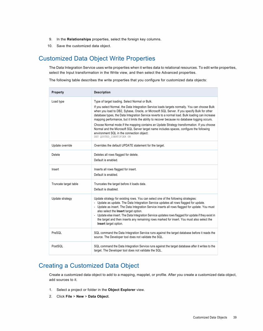
9. In the Relationships properties, select the foreign key columns.
10. Save the customized data object.
Customized Data Object Write PropertiesThe Data Integration Service uses write properties when it writes data to relational resources. To edit write properties,select the Input transformation in the Write view, and then select the Advanced properties.
The following table describes the write properties that you configure for customized data objects:
Property Description
Load type Type of target loading. Select Normal or Bulk.If you select Normal, the Data Integration Service loads targets normally. You can choose Bulkwhen you load to DB2, Sybase, Oracle, or Microsoft SQL Server. If you specify Bulk for otherdatabase types, the Data Integration Service reverts to a normal load. Bulk loading can increasemapping performance, but it limits the ability to recover because no database logging occurs.Choose Normal mode if the mapping contains an Update Strategy transformation. If you chooseNormal and the Microsoft SQL Server target name includes spaces, configure the followingenvironment SQL in the connection object:SET QUOTED_IDENTIFIER ON
Update override Overrides the default UPDATE statement for the target.
Delete Deletes all rows flagged for delete.Default is enabled.
Insert Inserts all rows flagged for insert.Default is enabled.
Truncate target table Truncates the target before it loads data.Default is disabled.
Update strategy Update strategy for existing rows. You can select one of the following strategies:- Update as update. The Data Integration Service updates all rows flagged for update.- Update as insert. The Data Integration Service inserts all rows flagged for update. You must
also select the Insert target option.- Update else insert. The Data Integration Service updates rows flagged for update if they exist in
the target and then inserts any remaining rows marked for insert. You must also select theInsert target option.
PreSQL SQL command the Data Integration Service runs against the target database before it reads thesource. The Developer tool does not validate the SQL.
PostSQL SQL command the Data Integration Service runs against the target database after it writes to thetarget. The Developer tool does not validate the SQL.
Creating a Customized Data ObjectCreate a customized data object to add to a mapping, mapplet, or profile. After you create a customized data object,add sources to it.
1. Select a project or folder in the Object Explorer view.
2. Click File > New > Data Object.
Customized Data Objects 39
The New dialog box appears.
3. Select Relational Data Object and click Next.
The New Relational Data Object dialog box appears.
4. Click Browse next to the Connection option and select a connection to the database.
5. Click Create customized data object.
6. Enter a name for the customized data object.
7. Click Browse next to the Location option and select the project where you want to create the customized dataobject.
8. Click Finish.
The customized data object appears under Physical Data Objects in the project or folder in the Object Explorerview.
Add sources to the customized data object. You can add relational resources or relational data objects as sources.You can also use a custom SQL query to add sources.
Adding Relational Resources to a Customized Data ObjectAfter you create a customized data object, add sources to it. You can use relational resources as sources.
Before you add relational resources to a customized data object, you must configure a connection to the database.
1. In the Connection Explorer view, select one or more relational resources in the same relational connection.
2. Right-click in the Connection Explorer view and select Add to project.
The Add to Project dialog box appears.
3. Select Add as related resource(s) to existing customized data object and click OK.
The Add to Data Object dialog box appears.
4. Select the customized data object and click OK.
5. If you add multiple resources to the customized data object, the Developer tool prompts you to select the resourceto write to. Select the resource and click OK.
If you use the customized data object in a mapping as a write transformation, the Developer tool writes data to thisresource.
The Developer tool adds the resources to the customized data object.
Adding Relational Data Objects to a Customized Data ObjectAfter you create a customized data object, add sources to it. You can use relational data objects as sources.
1. Open the customized data object.
2. Select the Read view.
3. In the Object Explorer view, select one or more relational data objects in the same relational connection.
4. Drag the objects from the Object Explorer view to the customized data object Read view.
5. If you add multiple relational data objects to the customized data object, the Developer tool prompts you to selectthe object to write to. Select the object and click OK.
If you use the customized data object in a mapping as a write transformation, the Developer tool writes data to thisrelational data object.
The Developer tool adds the relational data objects to the customized data object.
40 Chapter 3: Physical Data Objects
Custom QueriesA custom SQL query is a SELECT statement that overrides the default SQL query in a customized data object orrelational data object. When you define a custom query in a customized data object, you can reuse the object inmultiple mappings or profiles. When you define the query in a relational data object, you must define it for an instanceof the relational data object that is in a mapping, mapplet, or profile.
A custom query overrides the default SQL query that the Data Integration Service uses to read data from the sourcerelational resource. The custom query also overrides the simple query settings you define when you enter a sourcefilter, use sorted ports, enter a user-defined join, or select distinct ports.
Use the following guidelines when you create a custom query in a customized data object or relational data object:
¨ In the SELECT statement, list the column names in the order in which they appear in the source transformation.
¨ Enclose all database reserved words in quotes.
If you use a customized data object to perform a self-join, you must enter a custom SQL query that includes the self-join.
You can use a customized data object with a custom query as a read transformation in a mapping. The sourcedatabase executes the query before it passes data to the Data Integration Service.
You can create a custom query to add sources to an empty customized data object. You can also use a custom queryto override the default SQL query.
Creating a Custom QueryCreate a custom query to issue a special SELECT statement for reading data from the sources. The custom queryoverrides the default query that the Data Integration Service issues to read source data.
1. Open the customized data object or the relational data object instance.
2. Select the Read view.
3. Select the Output transformation.
4. Select the Query properties.
5. Select the advanced query.
6. Select Use custom query.
The Data Integration Service displays the query it issues to read source data.
7. Change the query or replace it with a custom query.
8. Save the data object.
Default QueryThe Data Integration Service generates a default SQL query that it uses to read data from relational sources. You canoverride the default query in a customized data object or an instance of a relational data object.
You can override the default query through the simple or advanced query. Use the simple query to select distinctvalues, enter a source filter, sort ports, or enter a user-defined join. Use the advanced query to create a custom SQLquery for reading data from the sources. The custom query overrides the default and simple queries.
If any table name or column name contains a database reserved word, you can create and maintain a reserved wordsfile, reswords.txt. Create the reswords.txt file on any machine the Data Integration Service can access.
Custom Queries 41
When the Data Integration Service runs a mapping, it searches for the reswords.txt file. If the file exists, the DataIntegration Service places quotes around matching reserved words when it executes SQL against the database. If youoverride the default query, you must enclose any database reserved words in quotes.
When the Data Integration Service generates the default query, it delimits table and field names containing thefollowing characters with double quotes:
/ + - = ~ ` ! % ^ & * ( ) [ ] { } ' ; ? , < > \ | <space>
Creating a Reserved Words FileCreate a reserved words file if any table name or column name in the customized data object contains a databasereserved word.
You must have administrator privileges to configure the Data Integration Service to use the reserved words file.
1. Create a file called "reswords.txt."
2. Create a section for each database by entering the database name within square brackets, for example,[Oracle].
3. Add the reserved words to the file below the database name.
For example:[Oracle]OPTIONSTARTwherenumber[SQL Server]CURRENTwherenumber
Entries are not case sensitive.
4. Save the reswords.txt file.
5. In Informatica Administrator, select the Data Integration Service.
6. Edit the custom properties.
7. Add the following custom property:
Name Value
Reserved Words File <path>\reswords.txt
8. Restart the Data Integration Service.
HintsYou can add hints to the source SQL query to pass instructions to a database optimizer. The optimizer uses the hintsto choose a query run plan to access the source.
The Hints field appears in the Query view of a relational data object instance or a customized data object. The sourcedatabase must be Oracle, Sybase, IBM DB2, or Microsoft SQL Server. The Hints field does not appear for otherdatabase types.
When the Data Integration Service generates the source query, it adds the SQL hints to the query exactly as you enterthem in the Developer tool. The Data Integration Service does not parse the hints. When you run the mapping thatcontains the source, the mapping log shows the query with the hints in the query.
42 Chapter 3: Physical Data Objects
The Data Integration Service inserts the SQL hints in a position in the query depending on the database type. Refer toyour database documentation for information about the syntax for hints.
OracleThe Data Integration Service add hints directly after the SELECT/UPDATE/INSERT/DELETE keyword.
SELECT /*+ <hints> */ FROM …
The '+' indicates the start of hints.
The hints are contained in a comment (/* ... */ or --... until end of line)
SybaseThe Data Integration Service adds hints after the query. Configure a plan name in the hint.
SELECT … PLAN <plan>
select avg(price) from titles plan "(scalar_agg (i_scan type_price_ix titles )"
IBM DB2You can enter the optimize-for clause as a hint. The Data Integration Service adds the clause at the end of thequery.
SELECT … OPTIMIZE FOR <n> ROWS
The optimize-for clause tells the database optimizer how many rows the query might process. The clause does notlimit the number of rows. If the database processes more than <n> rows, then performance might decrease.
Microsoft SQL ServerThe Data Integration Service adds hints at the end of the query as part of an OPTION clause.
SELECT … OPTION ( <query_hints> )
Hints Rules and Guidelines
Use the following rules and guidelines when you configure hints for SQL queries:
¨ If you enable pushdown optimization or if you use a semi-join in a relational data object, then the original sourcequery changes. The Data Integration Service does not apply hints to the modified query.
¨ You can combine hints with join and filter overrides, but if you configure a SQL override, the SQL override takesprecedence and the Data Integration Service does not apply the other overrides.
¨ The Query view shows a simple view or an advanced view. If you enter a hint with a filter, sort, or join override onthe simple view, and you the Developer tool shows the full query override on the advanced view.
Creating HintsCreate hints to send instructions to the database optimizer to determine a query plan.
1. Open the customized data object or the relational data object instance.
2. Select the Read view.
3. Select the Output transformation.
4. Select the Query properties.
5. Select the simple query.
6. Click Edit next to the Hints field.
The Hints dialog box appears.
Custom Queries 43
7. Enter the hint in the SQL Query field.
The Developer tool does not validate the hint.
8. Click OK.
9. Save the data object.
Select DistinctYou can select unique values from sources in a customized data object or a relational data object instance with theselect distinct option. When you enable select distinct, the Data Integration Service adds a SELECT DISTINCTstatement to the default SQL query.
Use the select distinct option to filter source data. For example, you might use the select distinct option to extractunique customer IDs from a table that lists total sales. When you use the relational data object in a mapping, the DataIntegration Service filters data earlier in the data flow, which can increase performance.
Using Select DistinctSelect unique values from a relational source with the Select Distinct property.
1. Open the customized data object or relational data object instance.
2. Select the Read view.
3. Select the Output transformation.
4. Select the Query properties.
5. Select the simple query.
6. Enable the Select Distinct option.
7. Save the customized data object.
FiltersYou can enter a filter value in a custom query. The filter becomes the WHERE clause in the query SELECT statement.Use a filter to reduce the number of rows that the Data Integration Service reads from the source table.
Entering a Source FilterEnter a source filter to reduce the number of rows the Data Integration Service reads from the relational source.
1. Open the customized data object or the relational data object instance.
2. Select the Read view.
3. Select the Output transformation.
4. Select the Query properties.
5. Select the simple query.
6. Click Edit next to the Filter field.
The SQL Query dialog box appears.
7. Enter the filter condition in the SQL Query field.
You can select column names from the Columns list.
8. Click OK.
44 Chapter 3: Physical Data Objects
9. Click Validate to validate the filter condition.
10. Save the data object.
Sorted PortsYou can sort rows in the default query for a customized data object or a relational data object instance. Select the portsto sort by. The Data Integration Service adds the ports to the ORDER BY clause in the default query.
You might sort the source rows to increase performance when you include the following transformations in amapping:
¨ Aggregator. When you configure an Aggregator transformation for sorted input, you can send sorted data by usingsorted ports. The group by ports in the Aggregator transformation must match the order of the sorted ports in thecustomized data object.
¨ Joiner. When you configure a Joiner transformation for sorted input, you can send sorted data by using sortedports. Configure the order of the sorted ports the same in each customized data object.
Note: You can also use the Sorter transformation to sort relational and flat file data before Aggregator and Joinertransformations.
Sorting Column DataUse sorted ports to sort column data in a customized data object or relational data object instance. When you use thedata object as a read transformation in a mapping or mapplet, you can pass the sorted data to transformationsdownstream from the read transformation.
1. Open the customized data object or relational data object instance.
2. Select the Read view.
3. Select the Output transformation.
4. Select the Query properties.
5. Select the simple query.
6. Click Edit next to the Sort field.
The Sort dialog box appears.
7. To specify a column as a sorted port, click the New button.
8. Select the column and sort type, either ascending or descending.
9. Repeat steps Using Sorted Ports and Using Sorted Ports to select other columns to sort.
The Developer tool sorts the columns in the order in which they appear in the Sort dialog box.
10. Click OK.
In the Query properties, the Developer tool displays the sort columns in the Sort field.
11. Click Validate to validate the sort syntax.
12. Save the data object.
User-Defined JoinsYou can configure a user-defined join in a customized data object or relational data object instance. A user-definedjoin defines the condition to join data from multiple sources in the same data object.
Custom Queries 45
When you add a user-defined join to a customized data object or a relational data object instance, you can use thedata object as a read transformation in a mapping. The source database performs the join before it passes data to theData Integration Service. Mapping performance increases when the source tables are indexed.
Creat a user-defined join to join data from related sources. The user-defined join overrides the default inner join thatthe Data Integration creates based on the related keys in each source. When you enter a user-defined join, enter thecontents of the WHERE clause that specifies the join condition. If the user-defined join performs an outer join, the DataIntegration Service might insert the join syntax in the WHERE clause or the FROM clause, based on the databasesyntax.
You might need to enter a user-defined join in the following circumstances:
¨ Columns do not have a primary key-foreign key relationship.
¨ The datatypes of columns used for the join do not match.
¨ You want to specify a different type of join, such as an outer join.
Use the following guidelines when you enter a user-defined join in a customized data object or relational data objectinstance:
¨ Do not include the WHERE keyword in the user-defined join.
¨ Enclose all database reserved words in quotes.
¨ If you use Informatica join syntax, and Enable quotes in SQL is enabled for the connection, you must enter quotesaround the table names and the column names if you enter them manually. If you select tables and columns whenyou enter the user-defined join, the Developer tool places quotes around the table names and the columnnames.
User-defined joins join data from related resources in a database. To join heterogeneous sources, use a Joinertransformation in a mapping that reads data from the sources. To perform a self-join, you must enter a custom SQLquery that includes the self-join.
Entering a User-Defined JoinConfigure a user-defined join in a customized data object or relational data object to define the join condition for thedata object sources.
1. Open the customized data object or relational data object instance.
2. Select the Read view.
3. Select the Output transformation.
4. Select the Query properties.
5. Select the simple query.
6. Click Edit next to the Join field.
The SQL Query dialog box appears.
7. Enter the user-defined join in the SQL Query field.
You can select column names from the Columns list.
8. Click OK.
9. Click Validate to validate the user-defined join.
10. Save the data object.
46 Chapter 3: Physical Data Objects
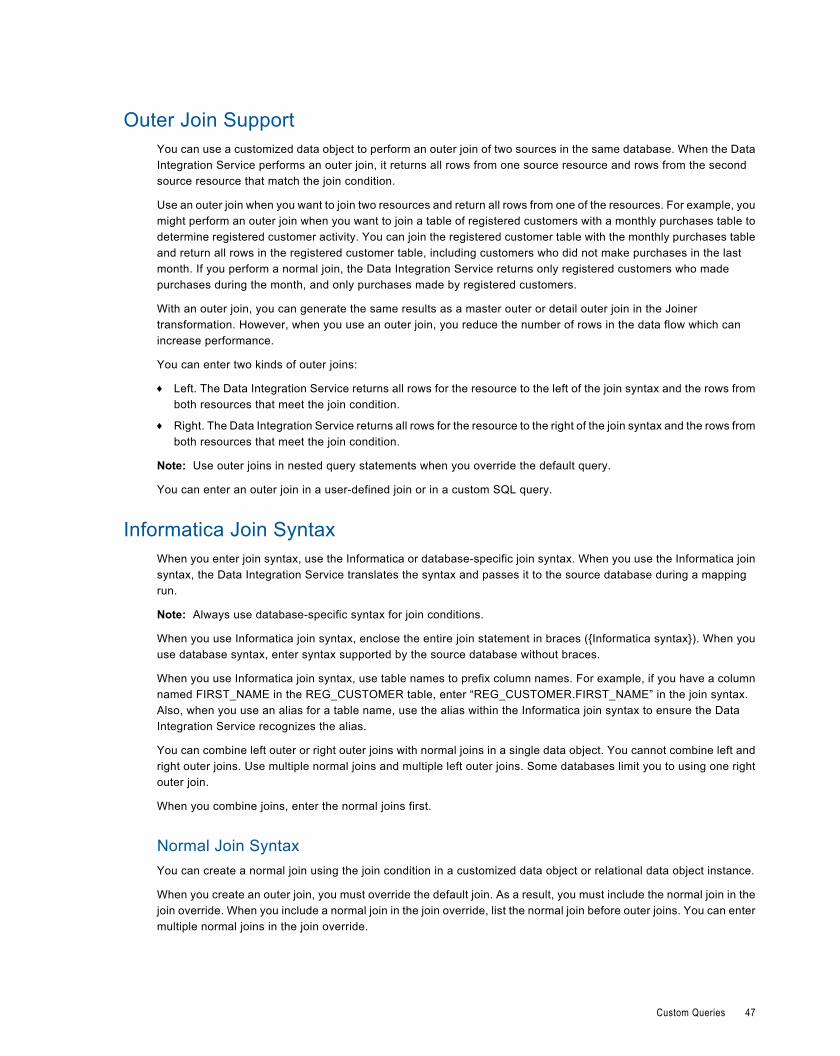
Outer Join SupportYou can use a customized data object to perform an outer join of two sources in the same database. When the DataIntegration Service performs an outer join, it returns all rows from one source resource and rows from the secondsource resource that match the join condition.
Use an outer join when you want to join two resources and return all rows from one of the resources. For example, youmight perform an outer join when you want to join a table of registered customers with a monthly purchases table todetermine registered customer activity. You can join the registered customer table with the monthly purchases tableand return all rows in the registered customer table, including customers who did not make purchases in the lastmonth. If you perform a normal join, the Data Integration Service returns only registered customers who madepurchases during the month, and only purchases made by registered customers.
With an outer join, you can generate the same results as a master outer or detail outer join in the Joinertransformation. However, when you use an outer join, you reduce the number of rows in the data flow which canincrease performance.
You can enter two kinds of outer joins:
¨ Left. The Data Integration Service returns all rows for the resource to the left of the join syntax and the rows fromboth resources that meet the join condition.
¨ Right. The Data Integration Service returns all rows for the resource to the right of the join syntax and the rows fromboth resources that meet the join condition.
Note: Use outer joins in nested query statements when you override the default query.
You can enter an outer join in a user-defined join or in a custom SQL query.
Informatica Join SyntaxWhen you enter join syntax, use the Informatica or database-specific join syntax. When you use the Informatica joinsyntax, the Data Integration Service translates the syntax and passes it to the source database during a mappingrun.
Note: Always use database-specific syntax for join conditions.
When you use Informatica join syntax, enclose the entire join statement in braces ({Informatica syntax}). When youuse database syntax, enter syntax supported by the source database without braces.
When you use Informatica join syntax, use table names to prefix column names. For example, if you have a columnnamed FIRST_NAME in the REG_CUSTOMER table, enter “REG_CUSTOMER.FIRST_NAME” in the join syntax.Also, when you use an alias for a table name, use the alias within the Informatica join syntax to ensure the DataIntegration Service recognizes the alias.
You can combine left outer or right outer joins with normal joins in a single data object. You cannot combine left andright outer joins. Use multiple normal joins and multiple left outer joins. Some databases limit you to using one rightouter join.
When you combine joins, enter the normal joins first.
Normal Join SyntaxYou can create a normal join using the join condition in a customized data object or relational data object instance.
When you create an outer join, you must override the default join. As a result, you must include the normal join in thejoin override. When you include a normal join in the join override, list the normal join before outer joins. You can entermultiple normal joins in the join override.
Custom Queries 47
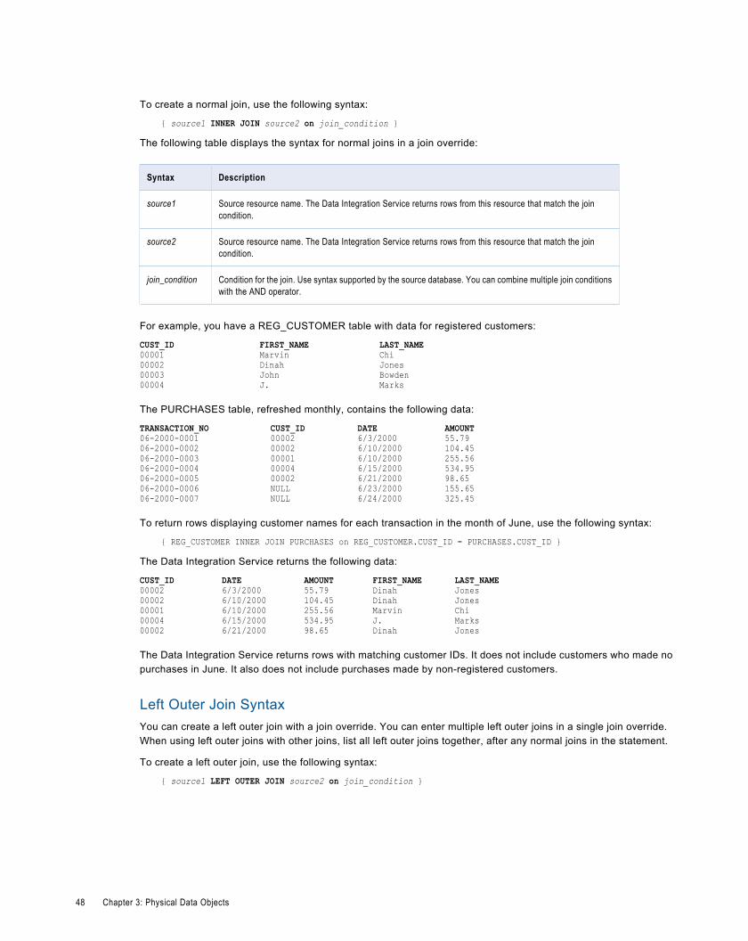
To create a normal join, use the following syntax:
{ source1 INNER JOIN source2 on join_condition }
The following table displays the syntax for normal joins in a join override:
Syntax Description
source1 Source resource name. The Data Integration Service returns rows from this resource that match the joincondition.
source2 Source resource name. The Data Integration Service returns rows from this resource that match the joincondition.
join_condition Condition for the join. Use syntax supported by the source database. You can combine multiple join conditionswith the AND operator.
For example, you have a REG_CUSTOMER table with data for registered customers:
CUST_ID FIRST_NAME LAST_NAME00001 Marvin Chi00002 Dinah Jones00003 John Bowden00004 J. Marks
The PURCHASES table, refreshed monthly, contains the following data:
TRANSACTION_NO CUST_ID DATE AMOUNT06-2000-0001 00002 6/3/2000 55.7906-2000-0002 00002 6/10/2000 104.4506-2000-0003 00001 6/10/2000 255.5606-2000-0004 00004 6/15/2000 534.9506-2000-0005 00002 6/21/2000 98.6506-2000-0006 NULL 6/23/2000 155.6506-2000-0007 NULL 6/24/2000 325.45
To return rows displaying customer names for each transaction in the month of June, use the following syntax:
{ REG_CUSTOMER INNER JOIN PURCHASES on REG_CUSTOMER.CUST_ID = PURCHASES.CUST_ID }
The Data Integration Service returns the following data:
CUST_ID DATE AMOUNT FIRST_NAME LAST_NAME00002 6/3/2000 55.79 Dinah Jones00002 6/10/2000 104.45 Dinah Jones00001 6/10/2000 255.56 Marvin Chi00004 6/15/2000 534.95 J. Marks00002 6/21/2000 98.65 Dinah Jones
The Data Integration Service returns rows with matching customer IDs. It does not include customers who made nopurchases in June. It also does not include purchases made by non-registered customers.
Left Outer Join SyntaxYou can create a left outer join with a join override. You can enter multiple left outer joins in a single join override.When using left outer joins with other joins, list all left outer joins together, after any normal joins in the statement.
To create a left outer join, use the following syntax:
{ source1 LEFT OUTER JOIN source2 on join_condition }
48 Chapter 3: Physical Data Objects
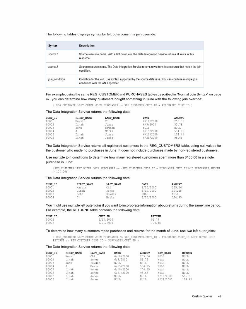
The following tables displays syntax for left outer joins in a join override:
Syntax Description
source1 Source resource name. With a left outer join, the Data Integration Service returns all rows in thisresource.
source2 Source resource name. The Data Integration Service returns rows from this resource that match the joincondition.
join_condition Condition for the join. Use syntax supported by the source database. You can combine multiple joinconditions with the AND operator.
For example, using the same REG_CUSTOMER and PURCHASES tables described in “Normal Join Syntax” on page47, you can determine how many customers bought something in June with the following join override:
{ REG_CUSTOMER LEFT OUTER JOIN PURCHASES on REG_CUSTOMER.CUST_ID = PURCHASES.CUST_ID }
The Data Integration Service returns the following data:
CUST_ID FIRST_NAME LAST_NAME DATE AMOUNT00001 Marvin Chi 6/10/2000 255.5600002 Dinah Jones 6/3/2000 55.7900003 John Bowden NULL NULL00004 J. Marks 6/15/2000 534.9500002 Dinah Jones 6/10/2000 104.4500002 Dinah Jones 6/21/2000 98.65
The Data Integration Service returns all registered customers in the REG_CUSTOMERS table, using null values forthe customer who made no purchases in June. It does not include purchases made by non-registered customers.
Use multiple join conditions to determine how many registered customers spent more than $100.00 in a singlepurchase in June:
{REG_CUSTOMER LEFT OUTER JOIN PURCHASES on (REG_CUSTOMER.CUST_ID = PURCHASES.CUST_ID AND PURCHASES.AMOUNT > 100.00) }
The Data Integration Service returns the following data:
CUST_ID FIRST_NAME LAST_NAME DATE AMOUNT00001 Marvin Chi 6/10/2000 255.5600002 Dinah Jones 6/10/2000 104.4500003 John Bowden NULL NULL00004 J. Marks 6/15/2000 534.95
You might use multiple left outer joins if you want to incorporate information about returns during the same time period.For example, the RETURNS table contains the following data:
CUST_ID CUST_ID RETURN00002 6/10/2000 55.7900002 6/21/2000 104.45
To determine how many customers made purchases and returns for the month of June, use two left outer joins:
{ REG_CUSTOMER LEFT OUTER JOIN PURCHASES on REG_CUSTOMER.CUST_ID = PURCHASES.CUST_ID LEFT OUTER JOIN RETURNS on REG_CUSTOMER.CUST_ID = PURCHASES.CUST_ID }
The Data Integration Service returns the following data:
CUST_ID FIRST_NAME LAST_NAME DATE AMOUNT RET_DATE RETURN00001 Marvin Chi 6/10/2000 255.56 NULL NULL00002 Dinah Jones 6/3/2000 55.79 NULL NULL00003 John Bowden NULL NULL NULL NULL00004 J. Marks 6/15/2000 534.95 NULL NULL00002 Dinah Jones 6/10/2000 104.45 NULL NULL00002 Dinah Jones 6/21/2000 98.65 NULL NULL00002 Dinah Jones NULL NULL 6/10/2000 55.7900002 Dinah Jones NULL NULL 6/21/2000 104.45
Custom Queries 49
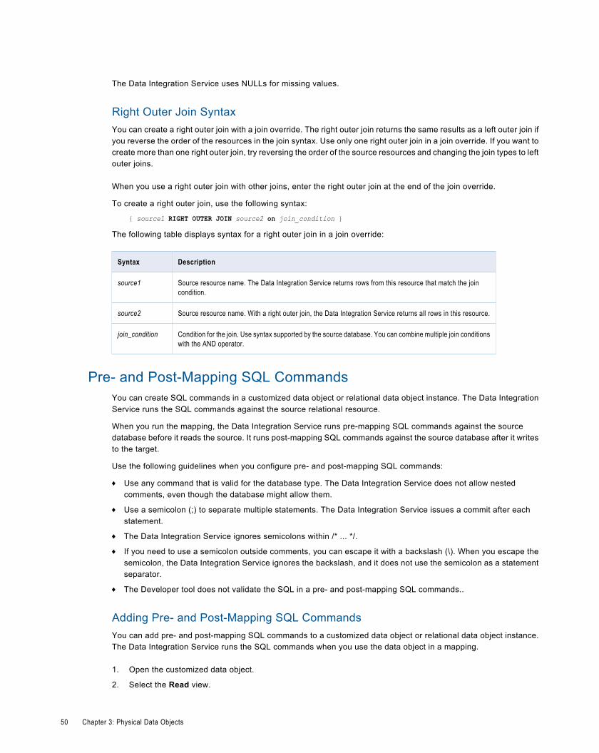
The Data Integration Service uses NULLs for missing values.
Right Outer Join SyntaxYou can create a right outer join with a join override. The right outer join returns the same results as a left outer join ifyou reverse the order of the resources in the join syntax. Use only one right outer join in a join override. If you want tocreate more than one right outer join, try reversing the order of the source resources and changing the join types to leftouter joins.
When you use a right outer join with other joins, enter the right outer join at the end of the join override.
To create a right outer join, use the following syntax:
{ source1 RIGHT OUTER JOIN source2 on join_condition }
The following table displays syntax for a right outer join in a join override:
Syntax Description
source1 Source resource name. The Data Integration Service returns rows from this resource that match the joincondition.
source2 Source resource name. With a right outer join, the Data Integration Service returns all rows in this resource.
join_condition Condition for the join. Use syntax supported by the source database. You can combine multiple join conditionswith the AND operator.
Pre- and Post-Mapping SQL CommandsYou can create SQL commands in a customized data object or relational data object instance. The Data IntegrationService runs the SQL commands against the source relational resource.
When you run the mapping, the Data Integration Service runs pre-mapping SQL commands against the sourcedatabase before it reads the source. It runs post-mapping SQL commands against the source database after it writesto the target.
Use the following guidelines when you configure pre- and post-mapping SQL commands:
¨ Use any command that is valid for the database type. The Data Integration Service does not allow nestedcomments, even though the database might allow them.
¨ Use a semicolon (;) to separate multiple statements. The Data Integration Service issues a commit after eachstatement.
¨ The Data Integration Service ignores semicolons within /* ... */.
¨ If you need to use a semicolon outside comments, you can escape it with a backslash (\). When you escape thesemicolon, the Data Integration Service ignores the backslash, and it does not use the semicolon as a statementseparator.
¨ The Developer tool does not validate the SQL in a pre- and post-mapping SQL commands..
Adding Pre- and Post-Mapping SQL CommandsYou can add pre- and post-mapping SQL commands to a customized data object or relational data object instance.The Data Integration Service runs the SQL commands when you use the data object in a mapping.
1. Open the customized data object.
2. Select the Read view.
50 Chapter 3: Physical Data Objects
3. Select the Output transformation
4. Select the Advanced properties.
5. Enter a pre-mapping SQL command in the PreSQL field.
6. Enter a post-mapping SQL command in the PostSQL field.
7. Save the customized data object.
Flat File Data ObjectsCreate or import a flat file data object to include in a mapping, mapplet, or profile. You can use flat file data objects assources, targets, and lookups in mappings and mapplets. You can create profiles on flat file data objects.
A flat file physical data object can be delimited or fixed-width. You can import fixed-width and delimited flat files that donot contain binary data.
After you import a flat file data object, you might need to create parameters or configure file properties. Createparameters through the Parameters view. Edit file properties through the Overview, Read, Write, and Advancedviews.
The Overview view allows you to edit the flat file data object name and description. It also allows you to update columnproperties for the flat file data object.
The Read view controls the properties that the Data Integration Service uses when it reads data from the flat file. TheRead view contains the following transformations:
¨ Source transformation. Defines the flat file that provides the source data. Select the source transformation to editproperties such as the name and description, column properties, and source file format properties.
¨ Output transformation. Represents the rows that the Data Integration Service reads when it runs a mapping. Selectthe Output transformation to edit the file run-time properties such as the source file name and directory.
The Write view controls the properties that the Data Integration Service uses when it writes data to the flat file. TheWrite view contains the following transformations:
¨ Input transformation. Represents the rows that the Data Integration Service writes when it runs a mapping. Selectthe Input transformation to edit the file run-time properties such as the target file name and directory.
¨ Target transformation. Defines the flat file that accepts the target data. Select the target transformation to edit thename and description and the target file format properties.
The Advanced view controls format properties that the Data Integration Service uses when it reads data from andwrites data to the flat file.
When you create mappings that use file sources or file targets, you can view flat file properties in the Properties view.You cannot edit file properties within a mapping, except for the reject file name, reject file directory, and tracinglevel.
Flat File Data Object Overview PropertiesThe Data Integration Service uses overview properties when it reads data from or writes data to a flat file. Overviewproperties include general properties, which apply to the flat file data object. They also include column properties,which apply to the columns in the flat file data object. The Developer tool displays overview properties for flat files inthe Overview view.
Flat File Data Objects 51
The following table describes the general properties that you configure for flat files:
Property Description
Name Name of the flat file data object.
Description Description of the flat file data object.
The following table describes the column properties that you configure for flat files:
Property Description
Name Name of the column.
Native type Native datatype of the column.
Bytes to process (fixed-widthflat files)
Number of bytes that the Data Integration Service reads or writes for the column.
Precision Maximum number of significant digits for numeric datatypes, or maximum number of charactersfor string datatypes. For numeric datatypes, precision includes scale.
Scale Maximum number of digits after the decimal point for numeric values.
Format Column format for numeric and datetime datatypes.For numeric datatypes, the format defines the thousand separator and decimal separator. Defaultis no thousand separator and a period (.) for the decimal separator.For datetime datatypes, the format defines the display format for year, month, day, and time. Italso defines the field width. Default is "A 19 YYYY-MM-DD HH24:MI:SS."
Visibility Determines whether the Data Integration Service can read data from or write data to thecolumn.For example, when the visibility is Read, the Data Integration Service can read data from thecolumn. It cannot write data to the column.For flat file data objects, this property is read-only. The visibility is always Read and Write.
Description Description of the column.
Flat File Data Object Read PropertiesThe Data Integration Service uses read properties when it reads data from a flat file. Select the source transformationto edit general, column, and format properties. Select the Output transformation to edit run-time properties.
General PropertiesThe Developer tool displays general properties for flat file sources in the source transformation in the Read view.
The following table describes the general properties that you configure for flat file sources:
Property Description
Name Name of the flat file.
52 Chapter 3: Physical Data Objects
Property Description
This property is read-only. You can edit the name in the Overview view. When you use the flat fileas a source in a mapping, you can edit the name within the mapping.
Description Description of the flat file.
Column PropertiesThe Developer tool displays column properties for flat file sources in the source transformation in the Read view.
The following table describes the column properties that you configure for flat file sources:
Property Description
Name Name of the column.
Native type Native datatype of the column.
Bytes to process (fixed-widthflat files)
Number of bytes that the Data Integration Service reads for the column.
Precision Maximum number of significant digits for numeric datatypes, or maximum number of charactersfor string datatypes. For numeric datatypes, precision includes scale.
Scale Maximum number of digits after the decimal point for numeric values.
Format Column format for numeric and datetime datatypes.For numeric datatypes, the format defines the thousand separator and decimal separator. Defaultis no thousand separator and a period (.) for the decimal separator.For datetime datatypes, the format defines the display format for year, month, day, and time. Italso defines the field width. Default is "A 19 YYYY-MM-DD HH24:MI:SS."
Shift key (fixed-width flat files) Allows the user to define a shift-in or shift-out statefulness for the column in the fixed-width flatfile.
Description Description of the column.
Format PropertiesThe Developer tool displays format properties for flat file sources in the source transformation in the Read view.
The following table describes the format properties that you configure for delimited flat file sources:
Property Description
Start import at line Row at which the Data Integration Service starts importing data. Use this option to skip headerrows.Default is 1.
Row delimiter Octal code for the character that separates rows of data.Default is line feed, \012 LF (\n).
Flat File Data Objects 53
Property Description
Escape character Character used to escape a delimiter character in an unquoted string if the delimiter is the nextcharacter after the escape character. If you specify an escape character, the Data IntegrationService reads the delimiter character as a regular character embedded in the string.Note: You can improve mapping performance slightly if the source file does not contain quotes orescape characters.
Retain escape character indata
Includes the escape character in the output string.Default is disabled.
Treat consecutive delimitersas one
Causes the Data Integration Service to treat one or more consecutive column delimiters as one.Otherwise, the Data Integration Service reads two consecutive delimiters as a null value.Default is disabled.
The following table describes the format properties that you configure for fixed-width flat file sources:
Property Description
Start import at line Row at which the Data Integration Service starts importing data. Use this option to skip headerrows.Default is 1.
Number of bytes to skipbetween records
Number of bytes between the last column of one row and the first column of the next. The DataIntegration Service skips the entered number of bytes at the end of each row to avoid readingcarriage return characters or line feed characters.Enter 1 for UNIX files and 2 for DOS files.Default is 2.
Line sequential Causes the Data Integration Service to read a line feed character or carriage return character inthe last column as the end of the column. Select this option if the file uses line feeds or carriagereturns to shorten the last column of each row.Default is disabled.
Strip trailing blanks Strips trailing blanks from string values.Default is disabled.
User defined shift state Allows you to select the shift state for source columns in the Columns properties.Select this option when the source file contains both multibyte and single-byte data, but does notcontain shift-in and shift-out keys. If a multibyte file source does not contain shift keys, you mustselect a shift key for each column in the flat file data object. Select the shift key for each column toenable the Data Integration Service to read each character correctly.Default is disabled.
54 Chapter 3: Physical Data Objects
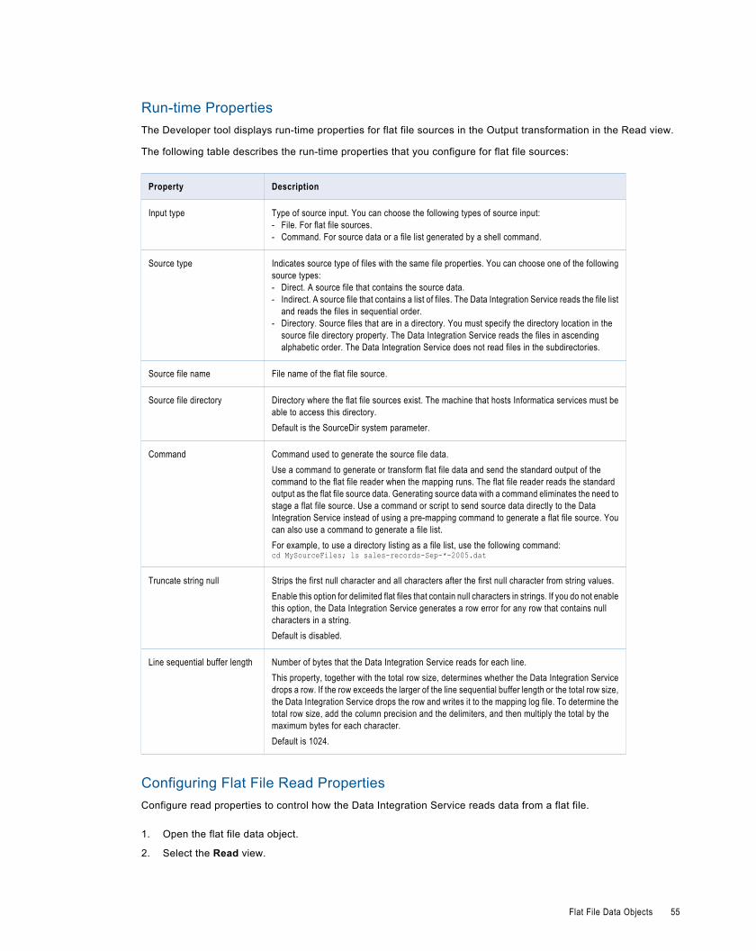
Run-time PropertiesThe Developer tool displays run-time properties for flat file sources in the Output transformation in the Read view.
The following table describes the run-time properties that you configure for flat file sources:
Property Description
Input type Type of source input. You can choose the following types of source input:- File. For flat file sources.- Command. For source data or a file list generated by a shell command.
Source type Indicates source type of files with the same file properties. You can choose one of the followingsource types:- Direct. A source file that contains the source data.- Indirect. A source file that contains a list of files. The Data Integration Service reads the file list
and reads the files in sequential order.- Directory. Source files that are in a directory. You must specify the directory location in the
source file directory property. The Data Integration Service reads the files in ascendingalphabetic order. The Data Integration Service does not read files in the subdirectories.
Source file name File name of the flat file source.
Source file directory Directory where the flat file sources exist. The machine that hosts Informatica services must beable to access this directory.Default is the SourceDir system parameter.
Command Command used to generate the source file data.Use a command to generate or transform flat file data and send the standard output of thecommand to the flat file reader when the mapping runs. The flat file reader reads the standardoutput as the flat file source data. Generating source data with a command eliminates the need tostage a flat file source. Use a command or script to send source data directly to the DataIntegration Service instead of using a pre-mapping command to generate a flat file source. Youcan also use a command to generate a file list.For example, to use a directory listing as a file list, use the following command:cd MySourceFiles; ls sales-records-Sep-*-2005.dat
Truncate string null Strips the first null character and all characters after the first null character from string values.Enable this option for delimited flat files that contain null characters in strings. If you do not enablethis option, the Data Integration Service generates a row error for any row that contains nullcharacters in a string.Default is disabled.
Line sequential buffer length Number of bytes that the Data Integration Service reads for each line.This property, together with the total row size, determines whether the Data Integration Servicedrops a row. If the row exceeds the larger of the line sequential buffer length or the total row size,the Data Integration Service drops the row and writes it to the mapping log file. To determine thetotal row size, add the column precision and the delimiters, and then multiply the total by themaximum bytes for each character.Default is 1024.
Configuring Flat File Read PropertiesConfigure read properties to control how the Data Integration Service reads data from a flat file.
1. Open the flat file data object.
2. Select the Read view.
Flat File Data Objects 55
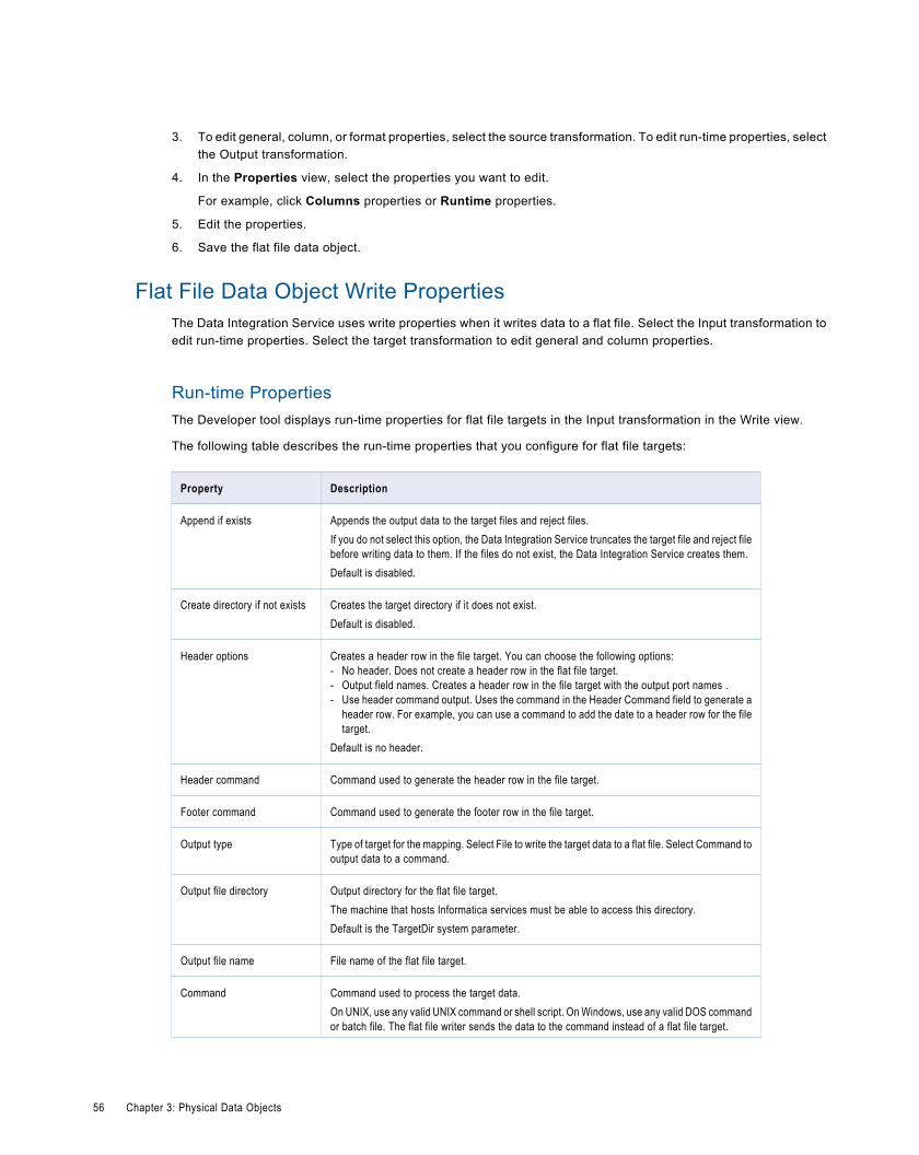
3. To edit general, column, or format properties, select the source transformation. To edit run-time properties, selectthe Output transformation.
4. In the Properties view, select the properties you want to edit.
For example, click Columns properties or Runtime properties.
5. Edit the properties.
6. Save the flat file data object.
Flat File Data Object Write PropertiesThe Data Integration Service uses write properties when it writes data to a flat file. Select the Input transformation toedit run-time properties. Select the target transformation to edit general and column properties.
Run-time PropertiesThe Developer tool displays run-time properties for flat file targets in the Input transformation in the Write view.
The following table describes the run-time properties that you configure for flat file targets:
Property Description
Append if exists Appends the output data to the target files and reject files.If you do not select this option, the Data Integration Service truncates the target file and reject filebefore writing data to them. If the files do not exist, the Data Integration Service creates them.Default is disabled.
Create directory if not exists Creates the target directory if it does not exist.Default is disabled.
Header options Creates a header row in the file target. You can choose the following options:- No header. Does not create a header row in the flat file target.- Output field names. Creates a header row in the file target with the output port names .- Use header command output. Uses the command in the Header Command field to generate a
header row. For example, you can use a command to add the date to a header row for the filetarget.
Default is no header.
Header command Command used to generate the header row in the file target.
Footer command Command used to generate the footer row in the file target.
Output type Type of target for the mapping. Select File to write the target data to a flat file. Select Command tooutput data to a command.
Output file directory Output directory for the flat file target.The machine that hosts Informatica services must be able to access this directory.Default is the TargetDir system parameter.
Output file name File name of the flat file target.
Command Command used to process the target data.On UNIX, use any valid UNIX command or shell script. On Windows, use any valid DOS commandor batch file. The flat file writer sends the data to the command instead of a flat file target.
56 Chapter 3: Physical Data Objects
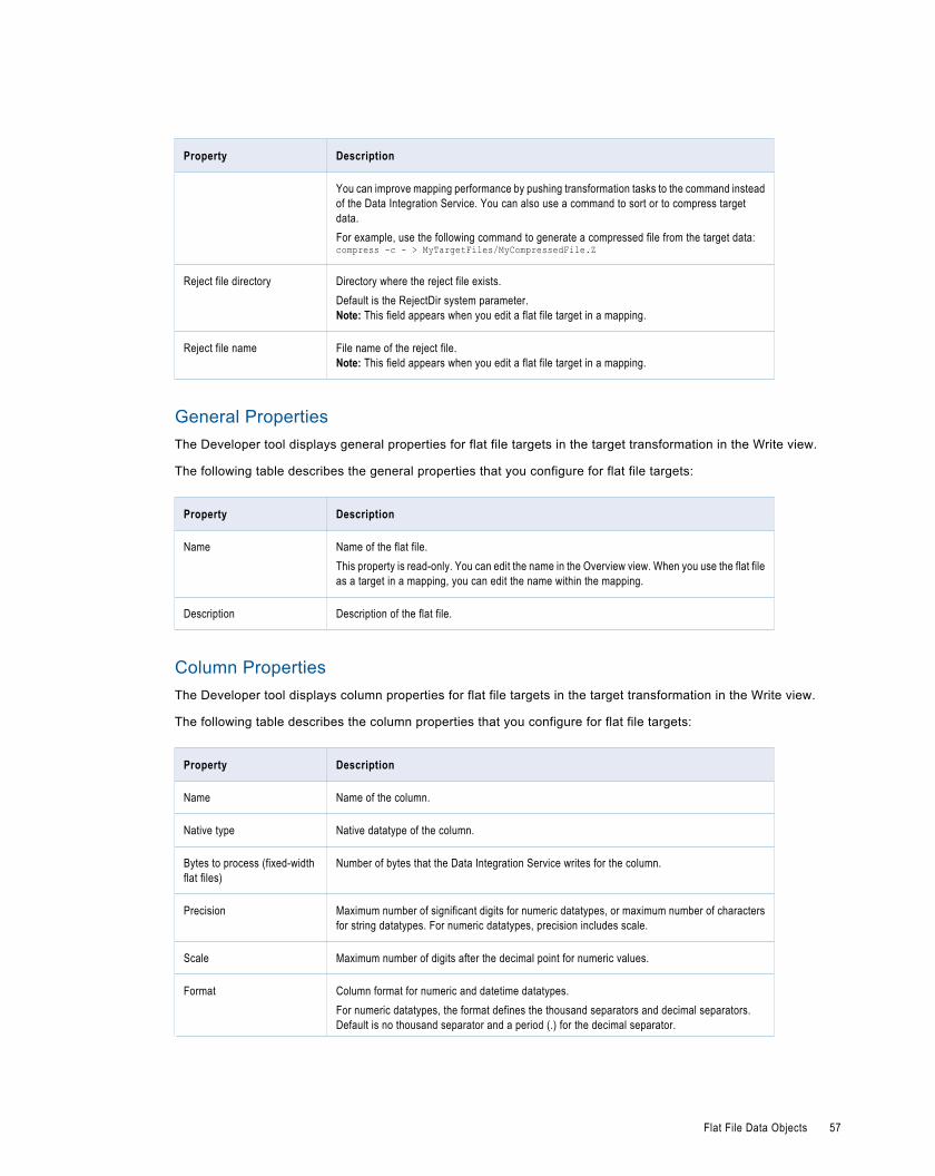
Property Description
You can improve mapping performance by pushing transformation tasks to the command insteadof the Data Integration Service. You can also use a command to sort or to compress targetdata.For example, use the following command to generate a compressed file from the target data:compress -c - > MyTargetFiles/MyCompressedFile.Z
Reject file directory Directory where the reject file exists.Default is the RejectDir system parameter.Note: This field appears when you edit a flat file target in a mapping.
Reject file name File name of the reject file.Note: This field appears when you edit a flat file target in a mapping.
General PropertiesThe Developer tool displays general properties for flat file targets in the target transformation in the Write view.
The following table describes the general properties that you configure for flat file targets:
Property Description
Name Name of the flat file.This property is read-only. You can edit the name in the Overview view. When you use the flat fileas a target in a mapping, you can edit the name within the mapping.
Description Description of the flat file.
Column PropertiesThe Developer tool displays column properties for flat file targets in the target transformation in the Write view.
The following table describes the column properties that you configure for flat file targets:
Property Description
Name Name of the column.
Native type Native datatype of the column.
Bytes to process (fixed-widthflat files)
Number of bytes that the Data Integration Service writes for the column.
Precision Maximum number of significant digits for numeric datatypes, or maximum number of charactersfor string datatypes. For numeric datatypes, precision includes scale.
Scale Maximum number of digits after the decimal point for numeric values.
Format Column format for numeric and datetime datatypes.For numeric datatypes, the format defines the thousand separators and decimal separators.Default is no thousand separator and a period (.) for the decimal separator.
Flat File Data Objects 57
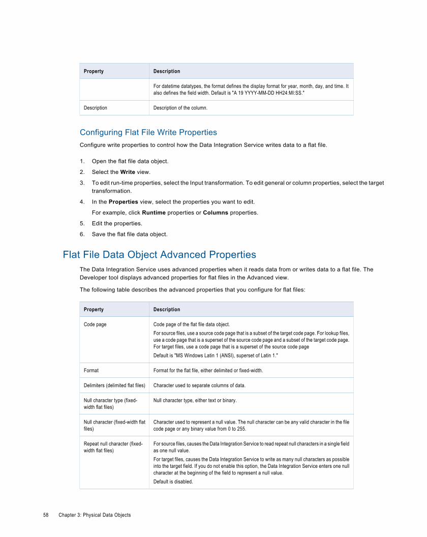
Property Description
For datetime datatypes, the format defines the display format for year, month, day, and time. Italso defines the field width. Default is "A 19 YYYY-MM-DD HH24:MI:SS."
Description Description of the column.
Configuring Flat File Write PropertiesConfigure write properties to control how the Data Integration Service writes data to a flat file.
1. Open the flat file data object.
2. Select the Write view.
3. To edit run-time properties, select the Input transformation. To edit general or column properties, select the targettransformation.
4. In the Properties view, select the properties you want to edit.
For example, click Runtime properties or Columns properties.
5. Edit the properties.
6. Save the flat file data object.
Flat File Data Object Advanced PropertiesThe Data Integration Service uses advanced properties when it reads data from or writes data to a flat file. TheDeveloper tool displays advanced properties for flat files in the Advanced view.
The following table describes the advanced properties that you configure for flat files:
Property Description
Code page Code page of the flat file data object.For source files, use a source code page that is a subset of the target code page. For lookup files,use a code page that is a superset of the source code page and a subset of the target code page.For target files, use a code page that is a superset of the source code pageDefault is "MS Windows Latin 1 (ANSI), superset of Latin 1."
Format Format for the flat file, either delimited or fixed-width.
Delimiters (delimited flat files) Character used to separate columns of data.
Null character type (fixed-width flat files)
Null character type, either text or binary.
Null character (fixed-width flatfiles)
Character used to represent a null value. The null character can be any valid character in the filecode page or any binary value from 0 to 255.
Repeat null character (fixed-width flat files)
For source files, causes the Data Integration Service to read repeat null characters in a single fieldas one null value.For target files, causes the Data Integration Service to write as many null characters as possibleinto the target field. If you do not enable this option, the Data Integration Service enters one nullcharacter at the beginning of the field to represent a null value.Default is disabled.
58 Chapter 3: Physical Data Objects
Property Description
Datetime format Defines the display format and the field width for datetime values.Default is "A 19 YYYY-MM-DD HH24:MI:SS."
Thousand separator Thousand separator for numeric values.Default is None.
Decimal separator Decimal separator for numeric values.Default is a period (.).
Tracing level Controls the amount of detail in the mapping log file.Note: This field appears when you edit a flat file source or target in a mapping.
Creating a Flat File Data ObjectCreate a flat file data object to define the data object columns and rows.
1. Select a project or folder in the Object Explorer view.
2. Click File > New > Data Object.
3. Select Physical Data Objects > Flat File Data Object and click Next.
The New Flat File Data Object dialog box appears.
4. Select Create as Empty.
5. Enter a name for the data object.
6. Optionally, click Browse to select a project or folder for the data object.
7. Click Next.
8. Select a code page that matches the code page of the data in the file.
9. Select Delimited or Fixed-width.
10. If you selected Fixed-width, click Finish. If you selected Delimited, click Next.
11. Configure the following properties:
Property Description
Delimiters Character used to separate columns of data. Use the Other field to enter adifferent delimiter. Delimiters must be printable characters and must bedifferent from the configured escape character and the quote character.You cannot select unprintable multibyte characters as delimiters.
Text Qualifier Quote character that defines the boundaries of text strings. If you select aquote character, the Developer tool ignores delimiters within a pair ofquotes.
12. Click Finish.
The data object appears under Data Object in the project or folder in the Object Explorer view.
Flat File Data Objects 59
Importing a Fixed-Width Flat File Data ObjectImport a fixed-width flat file data object when you have a fixed-width flat file that defines the metadata you want toinclude in a mapping, mapplet, or profile.
1. Click File > New > Data Object.
The New dialog box appears.
2. Select Physical Data Objects > Flat File Data Object and click Next.
The New Flat File Data Object dialog box appears.
3. Enter a name for the data object.
4. Click Browse and navigate to the directory that contains the file.
5. Click Open.
The wizard names the data object the same name as the file you selected.
6. Optionally, edit the data object name.
7. Click Next.
8. Select a code page that matches the code page of the data in the file.
9. Select Fixed-Width.
10. Optionally, edit the maximum number of rows to preview.
11. Click Next.
12. Configure the following properties:
Property Description
Import Field Names From First Line If selected, the Developer tool uses data in the first row for column names.Select this option if column names appear in the first row.
Start Import At Row Row number at which the Data Integration Service starts reading when itimports the file. For example, if you specify to start at the second row, theDeveloper tool skips the first row before reading.
13. Click Edit Breaks to edit column breaks. Or, follow the directions in the wizard to manipulate the column breaks inthe file preview window.
You can move column breaks by dragging them. Or, double-click a column break to delete it.
14. Click Next to preview the physical data object.
15. Click Finish.
The data object appears under Data Object in the project or folder in the Object Explorer view.
Importing a Delimited Flat File Data ObjectImport a delimited flat file data object when you have a delimited flat file that defines the metadata you want to includein a mapping, mapplet, or profile.
1. Select a project or folder in the Object Explorer view.
2. Click File > New > Data Object.
The New dialog box appears.
3. Select Physical Data Objects > Flat File Data Object and click Next.
60 Chapter 3: Physical Data Objects
The New Flat File Data Object dialog box appears.
4. Enter a name for the data object.
5. Click Browse and navigate to the directory that contains the file.
6. Click Open.
The wizard names the data object the same name as the file you selected.
7. Optionally, edit the data object name.
8. Click Next.
9. Select a code page that matches the code page of the data in the file.
10. Select Delimited.
11. Optionally, edit the maximum number of rows to preview.
12. Click Next.
13. Configure the following properties:
Property Description
Delimiters Character used to separate columns of data. Use the Other field to enter adifferent delimiter. Delimiters must be printable characters and must bedifferent from the configure escape character and the quote character. Youcannot select nonprinting multibyte characters as delimiters.
Text Qualifier Quote character that defines the boundaries of text strings. If you select aquote character, the Developer tool ignores delimiters within pairs ofquotes.
Import Field Names From First Line If selected, the Developer tool uses data in the first row for column names.Select this option if column names appear in the first row. The Developertool prefixes "FIELD_" to field names that are not valid.
Row Delimiter Specify a line break character. Select from the list or enter a character.Preface an octal code with a backslash (\). To use a single character, enterthe character.The Data Integration Service uses only the first character when the entry isnot preceded by a backslash. The character must be a single-bytecharacter, and no other character in the code page can contain that byte.Default is line-feed, \012 LF (\n).
Escape Character Character immediately preceding a column delimiter character embeddedin an unquoted string, or immediately preceding the quote character in aquoted string. When you specify an escape character, the Data IntegrationService reads the delimiter character as a regular character.
Start Import At Row Row number at which the Data Integration Service starts reading when itimports the file. For example, if you specify to start at the second row, theDeveloper tool skips the first row before reading.
Treat Consecutive Delimiters as One If selected, the Data Integration Service reads one or more consecutivecolumn delimiters as one. Otherwise, the Data Integration Service readstwo consecutive delimiters as a null value.
Remove Escape Character From Data Removes the escape character in the output string.
14. Click Next to preview the data object.
Flat File Data Objects 61
15. Click Finish.
The data object appears under Data Object in the project or folder in the Object Explorer view.
WSDL Data ObjectA WSDL data object is a physical data object that uses a WSDL file as a source. You can use a WSDL data object tocreate Web Service Consumer transformation. Import a WSDL file to create a WSDL data object.
After you import a WSDL data object, you can edit general and advanced properties in the Overview and Advancedviews. The WSDL view displays the WSDL file content.
Consider the following guidelines when you import a WSDL:
¨ The WSDL file must be WSDL 1.1 compliant.
¨ The WSDL file must be valid.
¨ Operations that you want to include in a Web Service Consumer transformation must use Document/Literalencoding. The WSDL import fails if all operations in the WSDL file use an encoding type other than Document/Literal.
¨ The Developer tool must be able to access any schema that the WSDL file references.
¨ If a WSDL file contains a schema or has an external schema, the Developer tool creates an embedded schemawithin the WSDL data object.
¨ If a WSDL file imports another WSDL file, the Developer tool combines both WSDLs to create the WSDL dataobject.
¨ If a WSDL file defines multiple operations, the Developer tool includes all operations in the WSDL data object.
WSDL Data Object Overview ViewThe WSDL data object Overview view displays general information about the WSDL and operations in the WSDL.
The following table describes the general properties that you configure for a WSDL data object:
Property Description
Name Name of the WSDL data object.
Description Description of the WSDL data object.
The following table describes the columns for operations defined in the WSDL data object:
Property Description
Operation The location where the WSDL defines the message format andprotocol for the operation.
Input The WSDL message name associated with the operationinput.
62 Chapter 3: Physical Data Objects
Property Description
Output The WSDL message name associated with the operationoutput.
Fault The WSDL message name associated with the operation fault.
WSDL Data Object Advanced ViewThe WSDL data object Advanced view displays advanced properties for a WSDL data object.
The following table describes the advanced properties for a WSDL data object:
Property Description
Connection Default web service connection for a Web Service Consumertransformation.
File Location Location where the WSDL file exists.
Importing a WSDL Data ObjectTo create a Web Service Consumer transformation, import a WSDL data object.You can import a WSDL data objectfrom a WSDL file or a URI that points to the WSDL location. You can import a WSDL data object from a WSDL file thatcontains either a SOAP 1.1 or SOAP 1.2 binding operation or both.
1. Click File > New > Data Object.
2. Select WSDL data object and click Next.
The New WSDL Data Object dialog box appears.
3. Click Browse next to the WSDL option and enter the location of the WSDL. Then, click OK.
When you enter the location of the WSDL, you can browse to the WSDL file or you can enter the URI to theWSDL.
Note: If the URI contains non-English characters, the import might fail. Copy the URI to the address bar in anybrowser. Copy the location back from the browser. The Developer tool accepts the encoded URI from thebrowser.
4. Enter a name for the WSDL.
5. Click Browse next to the Location option to select the project or folder location where you want to import theWSDL data object.
6. Click Next to view the operations in the WSDL.
7. Click Finish.
The data object appears under Physical Data Object in the project or folder in the Object Explorer view.
WSDL SynchronizationYou can synchronize a WSDL data object when the WSDL files change. When you synchronize a WSDL data object,the Developer tool reimports the object metadata from the WSDL files.
You use a WSDL data object to create a Web Service Consumer transformation. When you update a WSDL dataobject, the Developer tool updates the objects that reference the WSDL and marks them as changed when you open
WSDL Data Object 63
them. When the Developer tool compares the new WSDL with the old WSDL, it identifies WSDL components throughthe name attributes.
If no name attribute changes, the Developer tool updates the objects that reference the WSDL components. Forexample, you edit a WSDL file and change the type for simple element "CustID" from xs:string to xs:integer. When yousynchronize the WSDL data object, the Developer tool updates the element type in all Web Service Consumertransformations that reference the CustID element.
If a name attribute changes, the Developer tool marks the objects that reference the WSDL component as changedwhen you open them.
The Developer tool validates the WSDL files before it updates the WSDL data object. If the WSDL files contain errors,the Developer tool does not import the files.
Synchronizing a WSDL Data ObjectSynchronize a WSDL data object when the WSDL files change.
1. Right-click the WSDL data object in the Object Explorer view, and select Synchronize.
The Synchronize WSDL Data Object dialog box appears.
2. Click Browse next to the WSDL field, and enter the location of the WSDL. Then, click OK.
When you enter the location of the WSDL, you can browse to the WSDL file or you can enter the URI to theWSDL.
Note: If the URI contains non-English characters, the import might fail. Copy the URI to the address bar in anybrowser. Copy the location back from the browser. The Developer tool accepts the encoded URI from thebrowser.
3. Verify the WSDL name and location.
4. Click Next to view the operations in the WSDL.
5. Click Finish.
The Developer tool updates the objects that reference the WSDL and marks them as changed when you openthem.
Certificate ManagementThe Developer tool must use a certificate to import WSDL data objects and schema objects from a URL that requiresclient authentication.
By default, the Developer tool imports objects from URLs that require client authentication when the server that hoststhe URL uses a trusted certificate. When the server that hosts the URL uses an untrusted certificate, add the untrustedcertificate to the Developer tool. If you do not add the untrusted certificate to the Developer tool, the Developer toolcannot import the object. Request the certificate file and password from the server administrator for the URL that youwant import objects from.
The certificates that you add to the Developer tool apply to imports that you perform on the Developer tool machine.The Developer tool does not store certificates in the Model repository.
Informatica Developer Certificate PropertiesAdd certificates to the Developer tool when you want to import objects from a URL that requires client authenticationwith an untrusted certificate.
64 Chapter 3: Physical Data Objects
The following table describes the certificate properties:
Property Description
Host Name Name of the server that hosts the URL.
Port Number Port number of the URL.
Certificate File Path Location of the client certificate file.
Password Password for the client certificate file.
Adding Certificates to Informatica DeveloperWhen you add a certificate, you configure the certificate properties that the Developer tool uses when you importobjects from a URL that requires client authentication with an untrusted certificate.
1. Click Windows > Preferences.
2. Select Informatica > Web Services > Certificates.
3. Click Add.
4. Configure the certificate properties.
5. Click OK.
SynchronizationYou can synchronize physical data objects when their sources change. When you synchronize a physical data object,the Developer tool reimports the object metadata from the source you select.
You can synchronize all physical data objects. When you synchronize relational data objects or customized dataobjects, you can retain or overwrite the key relationships you define in the Developer tool.
You can configure a customized data object to be synchronized when its sources change. For example, a customizeddata object uses a relational data object as a source, and you add a column to the relational data object. TheDeveloper tool adds the column to the customized data object. To synchronize a customized data object when itssources change, select the Synchronize input and output option in the Overview properties of the customized dataobject.
To synchronize any physical data object, right-click the object in the Object Explorer view, and selectSynchronize.
Troubleshooting Physical Data Objects
I am trying to preview a relational data object or a customized data object source transformation and the previewfails.Verify that the resource owner name is correct.
Synchronization 65

When you import a relational resource, the Developer tool imports the owner name when the user name and schemafrom which the table is imported do not match. If the user name and schema from which the table is imported match,but the database default schema has a different name, preview fails because the Data Integration Service executesthe preview query against the database default schema, where the table does not exist.
Update the relational data object or the source transformation and enter the correct resource owner name. The ownername appears in the relational data object or the source transformation Advanced properties.
I am trying to preview a flat file data object and the preview fails. I get an error saying that the system cannot find thepath specified.Verify that the machine that hosts Informatica services can access the source file directory.
For example, you create a flat file data object by importing the following file on your local machine, MyClient:
C:\MySourceFiles\MyFile.csv
In the Read view, select the Runtime properties in the Output transformation. The source file directory is "C:\MySourceFiles."
When you preview the file, the Data Integration Service tries to locate the file in the "C:\MySourceFiles" directory onthe machine that hosts Informatica services. If the directory does not exist on the machine that hosts Informaticaservices, the Data Integration Service returns an error when you preview the file.
To work around this issue, use the network path as the source file directory. For example, change the source filedirectory from "C:\MySourceFiles" to "\\MyClient\MySourceFiles." Share the "MySourceFiles" directory so that themachine that hosts Informatica services can access it.
66 Chapter 3: Physical Data Objects
C H A P T E R 4
Schema ObjectThis chapter includes the following topics:
¨ Schema Object Overview, 67
¨ Schema Object Overview View, 67
¨ Schema Object Schema View, 68
¨ Schema Object Advanced View, 72
¨ Importing a Schema Object, 73
¨ Schema Changes, 73
¨ Certificate Management, 75
Schema Object OverviewA schema object is an XML schema that you import to the Model repository. After you import the schema, you can viewthe schema components in the Developer tool.
When you import a schema you can edit general schema properties in the Overview view. Edit advanced properties inthe Advanced view. View the schema file content in the Schema view.
Schema Object Overview ViewSelect the Overview view to update the schema name or schema description, view namespaces, and manageschema files.
The Overview view shows the name, description, and target namespace for the schema. You can edit the schemaname and the description. The target namespace displays the namespace to which the schema components belong. Ifno target namespace appears, the schema components do not belong to a namespace.
The Schema Locations area lists the schema files and the namespaces. You can add multiple root .xsd files. If aschema file includes or imports other schema files, the Developer tool includes the child .xsd files in the schema.
The namespace associated with each schema file differentiates between elements that come from different sourcesbut have the same names. A Uniform Resource Identifier (URI) reference defines the location of the file that containsthe elements and attribute names.
67
Schema FilesYou can add multiple root-level .xsd files to a schema object. You can also remove root-level .xsd files from a schemaobject.
When you add a schema file, the Developer tool imports all .xsd files that are imported by or included in the file youadd. The Developer tool validates the files you add against the files that are part of the schema object. The Developertool does not allow you to add a file if the file conflicts with a file that is part of the schema object.
For example, a schema object contains root schema file "BostonCust.xsd." You want to add root schema file"LACust.xsd" to the schema object. Both schema files have the same target namespace and define an element called"Customer." When you try to add schema file LACust.xsd to the schema object, the Developer tool prompts you toretain the BostonCust.xsd file or overwrite it with the LACust.xsd file.
You can remove any root-level schema file. If you remove a schema file, the Developer tool changes the element typeof elements that were defined by the schema file to xs:string.
To add a schema file, select the Overview view, and click the Add button next to the Schema Locations list. Then,select the schema file. To remove a schema file, select the file and click the Remove button.
Schema Object Schema ViewThe Schema view shows an alphabetic list of the groups, elements, types, attribute groups, and attributes in theschema. When you select a group, element, type, attribute group, or attribute in the Schema view, properties displayin the right panel. You can also view each .xsd file in the Schema view.
The Schema view provides a list of the namespaces and the .xsd files in the schema object.
You can perform the following actions in the Schema view:
¨ To view the list of schema constructs, expand the Directives folder. To view the namespace, prefix, and thelocation, select a schema construct from the list.
¨ To view the namespace prefix, generated prefix, and location, select a namespace. You can change the generatedprefix.
¨ To view the schema object as an .xsd file, select Source. If the schema object includes other schemas, you canselect which .xsd file to view.
¨ To view an alphabetic list of groups, elements, types, attribute groups, and attributes in each namespace of theschema, select Design. You can enter one or more characters in the Name field to filter the groups, elements,types, attribute groups, and attributes by name.
¨ To view the element properties, select a group, element, type, attribute group, or attribute. The Developer tooldisplays different fields in the right panel based on the object you select.
When you view types, you can see whether a type is derived from another type. The interface shows the parent type.The interface also shows whether the child element inherited values by restriction or extension.
Namespace PropertiesThe Namespace view shows the prefix and location for a selected namespace.
When you import an XML schema that contains more than one namespace, the Developer tool adds the namespacesto the schema object. When the schema file includes other schemas, the namespaces for those schemas are alsoincluded.
68 Chapter 4: Schema Object
The Developer tool creates a generated prefix for each namespace. When the XML schema does not contain a prefix,the Developer tool generates the namespace prefix tns0 and increments the prefix number for each additionalnamespace prefix. The Developer tool reserves the namespace prefix xs. If you import an XML schema that containsthe namespace prefix xs, the Developer tool creates the generated prefix xs1. The Developer tool increments theprefix number when the schema contains the generated prefix value.
For example, Customer_Orders.xsd has a namespace. The schema includes another schema, Customers.xsd. TheCustomers schema has a different namespace. The Developer tool assigns prefix tns0 to the Customer_Ordersnamespace and prefix tns1 to the Customers namespace.
To view the namespace location and prefix, select a namespace in the Schema view.
Element PropertiesAn element is a simple or a complex type. A complex type contains other types. When you select an element in theSchema view, the Developer tool lists the child elements and the properties in the right panel of the screen.
The following table describes element properties that appear when you select an element:
Property Description
Name The element name.
Description Description of the type.
Type The element type.
The following table describes the child element properties that appear when you select an element:
Property Description
Name The element name.
Type The element type.
Minimum Occurs The minimum number of times that the element can occur at one point in an XML instance.
Maximum Occurs The maximum number of times that the element can occur at one point in an XML instance.
Description Description of the element.
To view additional child element properties, click the double arrow in the Description column to expand the window.
The following table describes the additional child element properties that appear when you expand the Descriptioncolumn:
Property Description
Fixed Value A specific value for an element that does not change.
Nillable The element can have nil values. A nil element has element tags but has no value and no content.
Abstract The element is an abstract type. An XML instance must include types derived from that type. An abstract type isnot a valid type without derived element types.
Schema Object Schema View 69
Property Description
Minimum Value The minimum value for an element in an XML instance.
Maximum Value The maximum value for an element in an XML instance.
Minimum Length The minimum length of an element. Length is in bytes, characters, or items based on the element type.
Maximum Length The maximum length of an element. Length is in bytes, characters, or items based on the element type.
Enumeration A list of all legal values for an element.
Pattern An expression pattern that defines valid element values.
Element Advanced PropertiesTo view advanced properties for a element, select the element in the Schema view. Click Advanced.
The following table describes the element advanced properties:
Property Description
Abstract The element is an abstract type. A SOAP message must include types derived from that type. An abstract typeis not a valid type without derived element types.
Block Prevents a derived element from appearing in the XML in place of this element. The block value can contain"#all" or a list that includes extension, restriction, or substitution.
Final Prevents the schema from extending or restricting the simple type as a derived type.
Substitution Group The name of an element to substitute with the element.
Nillible The element can have nil values. A nil element has element tags but has no value and no content.
Simple Type PropertiesA simple type element is an XML element that contains unstructured text. When you select a simple type element inthe Schema view, information about the simple type element appears in the right panel.
The following table describes the properties you can view for a simple type:
Property Description
Type Name of the element.
Description Description of the element.
Variety Defines if the simple type is union, list, anyType, or atomic. An atomic element contains no other elementsor attributes.
Member types A list of the types in a UNION construct.
Item type The element type.
70 Chapter 4: Schema Object
Property Description
Base The base type of an atomic element, such as integer or string.
Minimum Length The minimum length for an element. Length is in bytes, characters, or items based on the element type.
Maximum Length The maximum length for an element. Length is in bytes, characters, or items based on the element type.
Collapse whitespace Strips leading and trailing whitespace. Collapses multiple spaces to a single space.
Enumerations Restrict the type to the list of legal values.
Patterns Restrict the type to values defined by a pattern expression.
Simple Type Advanced PropertiesTo view advanced properties for a simple type, select the simple type in the Schema view. Click Advanced.
The advanced properties appear below the simple type properties.
The following table describes the advanced property for a simple type:
Property Description
Final Prevents the schema from extending or restricting the simple type as a derived type.
Complex Type PropertiesA complex type is an XML element that contains other elements and attributes. A complex type contains elements thatare simple or complex types. When you select a complex type in the Schema view, the Developer tool lists the childelements and the child element properties in the right panel of the screen.
The following table describes complex type properties:
Property Description
Name The type name.
Description Description of the type.
Inherit from Name of the parent type.
Inherit by Restriction or extension. A complex type is derived from a parent type. The complex type might reduce the elementsor attributes of the parent. Or, it might add elements and attributes.
To view properties of each element in a complex type, click the double arrow in the Description column to expand thewindow.
Complex Type Advanced PropertiesTo view advanced properties for a complex type, select the element in the Schema view. Click Advanced.
Schema Object Schema View 71
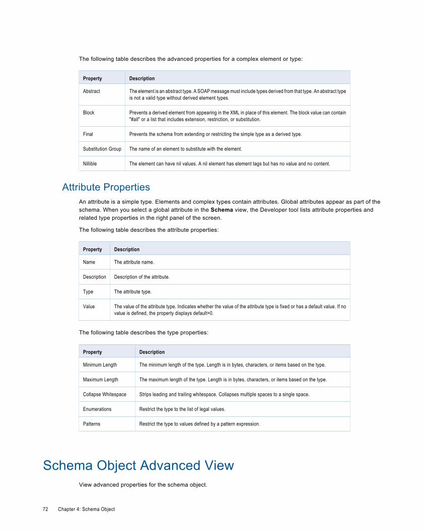
The following table describes the advanced properties for a complex element or type:
Property Description
Abstract The element is an abstract type. A SOAP message must include types derived from that type. An abstract typeis not a valid type without derived element types.
Block Prevents a derived element from appearing in the XML in place of this element. The block value can contain"#all" or a list that includes extension, restriction, or substitution.
Final Prevents the schema from extending or restricting the simple type as a derived type.
Substitution Group The name of an element to substitute with the element.
Nillible The element can have nil values. A nil element has element tags but has no value and no content.
Attribute PropertiesAn attribute is a simple type. Elements and complex types contain attributes. Global attributes appear as part of theschema. When you select a global attribute in the Schema view, the Developer tool lists attribute properties andrelated type properties in the right panel of the screen.
The following table describes the attribute properties:
Property Description
Name The attribute name.
Description Description of the attribute.
Type The attribute type.
Value The value of the attribute type. Indicates whether the value of the attribute type is fixed or has a default value. If novalue is defined, the property displays default=0.
The following table describes the type properties:
Property Description
Minimum Length The minimum length of the type. Length is in bytes, characters, or items based on the type.
Maximum Length The maximum length of the type. Length is in bytes, characters, or items based on the type.
Collapse Whitespace Strips leading and trailing whitespace. Collapses multiple spaces to a single space.
Enumerations Restrict the type to the list of legal values.
Patterns Restrict the type to values defined by a pattern expression.
Schema Object Advanced ViewView advanced properties for the schema object.
72 Chapter 4: Schema Object
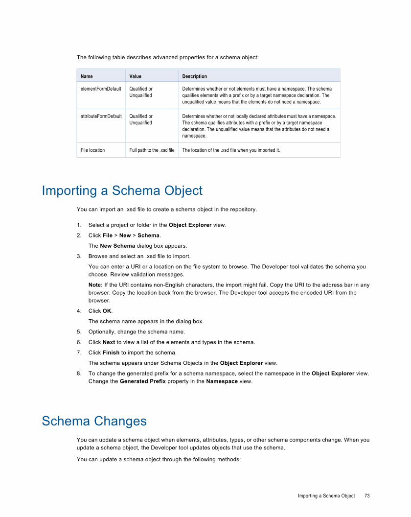
The following table describes advanced properties for a schema object:
Name Value Description
elementFormDefault Qualified orUnqualified
Determines whether or not elements must have a namespace. The schemaqualifies elements with a prefix or by a target namespace declaration. Theunqualified value means that the elements do not need a namespace.
attributeFormDefault Qualified orUnqualified
Determines whether or not locally declared attributes must have a namespace.The schema qualifies attributes with a prefix or by a target namespacedeclaration. The unqualified value means that the attributes do not need anamespace.
File location Full path to the .xsd file The location of the .xsd file when you imported it.
Importing a Schema ObjectYou can import an .xsd file to create a schema object in the repository.
1. Select a project or folder in the Object Explorer view.
2. Click File > New > Schema.
The New Schema dialog box appears.
3. Browse and select an .xsd file to import.
You can enter a URI or a location on the file system to browse. The Developer tool validates the schema youchoose. Review validation messages.
Note: If the URI contains non-English characters, the import might fail. Copy the URI to the address bar in anybrowser. Copy the location back from the browser. The Developer tool accepts the encoded URI from thebrowser.
4. Click OK.
The schema name appears in the dialog box.
5. Optionally, change the schema name.
6. Click Next to view a list of the elements and types in the schema.
7. Click Finish to import the schema.
The schema appears under Schema Objects in the Object Explorer view.
8. To change the generated prefix for a schema namespace, select the namespace in the Object Explorer view.Change the Generated Prefix property in the Namespace view.
Schema ChangesYou can update a schema object when elements, attributes, types, or other schema components change. When youupdate a schema object, the Developer tool updates objects that use the schema.
You can update a schema object through the following methods:
Importing a Schema Object 73
Synchronize the schema.
Synchronize a schema object when you update the schema files outside the Developer tool. When yousynchronize a schema object, the Developer tool reimports all of the schema .xsd files that contain changes.
Edit a schema file.
Edit a schema file when you want to update a file from within the Developer tool. When you edit a schema file, theDeveloper tool opens the file in the editor you use for .xsd files. You can open the file in a different editor or set adefault editor for .xsd files in the Developer tool.
Schema SynchronizationYou can synchronize a schema object when the schema components change. When you synchronize a schemaobject, the Developer tool reimports the object metadata from the schema files.
Use schema synchronization when you make complex changes to the schema object outside the Developer tool. Forexample, you might synchronize a schema after you perform the following actions:
¨ Make changes to multiple schema files.
¨ Add or remove schema files from the schema.
¨ Change import or include elements.
The Developer tool validates the schema files before it updates the schema object. If the schema files contain errors,the Developer tool does not import the files.
To synchronize a schema object, right-click the schema object in the Object Explorer view, and selectSynchronize.
Schema File EditsYou can edit a schema file from within the Developer tool to update schema components.
Edit a schema file in the Developer tool to make minor updates to a small number of files. For example, you mightmake one of the following minor updates to a schema file:
¨ Change the minOccurs or maxOccurs attributes for an element.
¨ Add an attribute to a complex type.
¨ Change a simple object type.
When you edit a schema file, the Developer tool opens a temporary copy of the schema file in an editor. You can editschema files with the system editor that you use for .xsd files, or you can select another editor. You can also set theDeveloper tool default editor for .xsd files. Save the temporary schema file after you edit it.
The Developer tool validates the temporary file before it updates the schema object. If the schema file contains errorsor contains components that conflict with other schema files in the schema object, the Developer tool does not importthe file.
Note: When you edit and save the temporary schema file, the Developer tool does not update the schema file thatappears in the Schema Location list. If you synchronize a schema object after you edit a schema file in the Developertool, the synchronization operation overwrites your edits.
Setting a Default Schema File EditorYou can set the default editor that the Developer tool opens when you edit a schema file.
1. Select Window > Preferences.
The Preferences dialog box appears.
74 Chapter 4: Schema Object
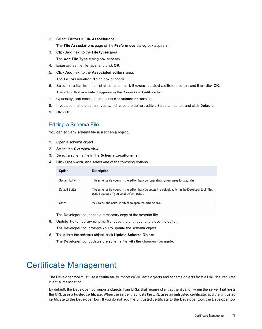
2. Select Editors > File Associations.
The File Associations page of the Preferences dialog box appears.
3. Click Add next to the File types area.
The Add File Type dialog box appears.
4. Enter xsd as the file type, and click OK.
5. Click Add next to the Associated editors area.
The Editor Selection dialog box appears.
6. Select an editor from the list of editors or click Browse to select a different editor, and then click OK.
The editor that you select appears in the Associated editors list.
7. Optionally, add other editors to the Associated editors list.
8. If you add multiple editors, you can change the default editor. Select an editor, and click Default.
9. Click OK.
Editing a Schema FileYou can edit any schema file in a schema object.
1. Open a schema object.
2. Select the Overview view.
3. Select a schema file in the Schema Locations list.
4. Click Open with, and select one of the following options:
Option Description
System Editor The schema file opens in the editor that your operating system uses for .xsd files.
Default Editor The schema file opens in the editor that you set as the default editor in the Developer tool. Thisoption appears if you set a default editor.
Other You select the editor in which to open the schema file.
The Developer tool opens a temporary copy of the schema file.
5. Update the temporary schema file, save the changes, and close the editor.
The Developer tool prompts you to update the schema object.
6. To update the schema object, click Update Schema Object.
The Developer tool updates the schema file with the changes you made.
Certificate ManagementThe Developer tool must use a certificate to import WSDL data objects and schema objects from a URL that requiresclient authentication.
By default, the Developer tool imports objects from URLs that require client authentication when the server that hoststhe URL uses a trusted certificate. When the server that hosts the URL uses an untrusted certificate, add the untrustedcertificate to the Developer tool. If you do not add the untrusted certificate to the Developer tool, the Developer tool
Certificate Management 75
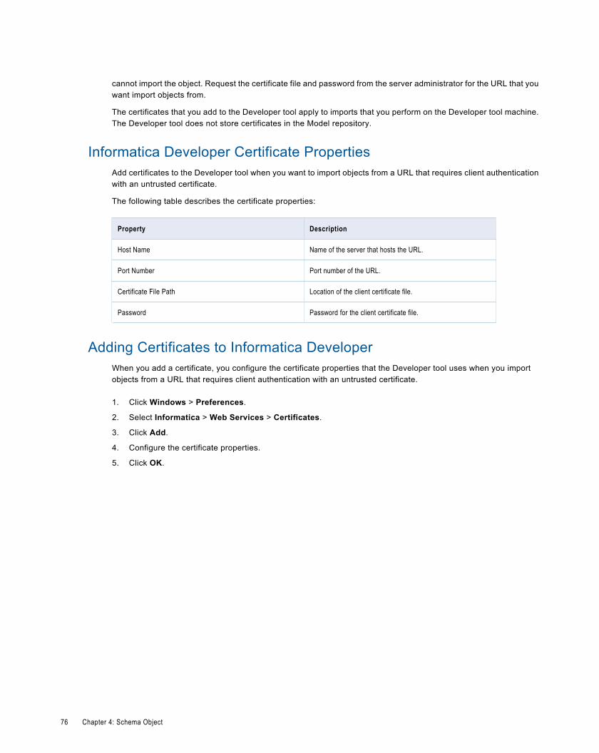
cannot import the object. Request the certificate file and password from the server administrator for the URL that youwant import objects from.
The certificates that you add to the Developer tool apply to imports that you perform on the Developer tool machine.The Developer tool does not store certificates in the Model repository.
Informatica Developer Certificate PropertiesAdd certificates to the Developer tool when you want to import objects from a URL that requires client authenticationwith an untrusted certificate.
The following table describes the certificate properties:
Property Description
Host Name Name of the server that hosts the URL.
Port Number Port number of the URL.
Certificate File Path Location of the client certificate file.
Password Password for the client certificate file.
Adding Certificates to Informatica DeveloperWhen you add a certificate, you configure the certificate properties that the Developer tool uses when you importobjects from a URL that requires client authentication with an untrusted certificate.
1. Click Windows > Preferences.
2. Select Informatica > Web Services > Certificates.
3. Click Add.
4. Configure the certificate properties.
5. Click OK.
76 Chapter 4: Schema Object
C H A P T E R 5
ProfilesThis chapter includes the following topics:
¨ Profiles Overview, 77
¨ Column Profiling Process, 77
¨ Column Profile Options, 78
¨ Creating a Profile, 79
¨ Profile Views, 79
¨ Column Profile Results, 80
¨ Exporting Profile Results from Informatica Developer, 81
¨ Synchronizing a Flat File Data Object, 82
¨ Synchronizing a Relational Data Object, 82
Profiles OverviewA column profile determines the characteristics of columns in a data source, such as value frequency, percentages,and patterns.
Column profiling discovers the following facts about data:
¨ The number of unique and null values in each column, expressed as a number and a percentage.
¨ The patterns of data in each column and the frequencies with which these values occur.
¨ Statistics about the column values, such as the maximum and minimum lengths of values and the first and lastvalues in each column.
Use column profile options to select the columns on which you want to run a profile, set data sampling options, and setdrill-down options when you create a profile.
A rule is business logic that defines conditions applied to source data when you run a profile. You can add a rule to theprofile to cleanse, change, or validate data.
Column Profiling ProcessAs part of the column profiling process, you can choose to create a quick profile or a custom profile for a dataobject.
77
Use a quick profile to include all columns for a data object and use the default profile options. Use a custom profile toselect the columns for a data object and to configure the profile results, sampling, and drill-down options.
The following steps describe the column profiling process:
1. Select the data object you want to profile.
2. Determine whether you want to create a quick profile or a custom profile.
3. Choose where you want to save the profile.
4. Select the columns you want to profile.
5. Select the profile results option.
6. Choose the sampling options.
7. Choose the drilldown options.
8. Define a filter to determine the rows that the profile reads at run time.
9. Run the profile.
Column Profile OptionsWhen you create a profile with the Column Profiling option, you can use the profile wizard to define filter andsampling options. These options determine how the profile reads rows from the data set.
After you complete the steps in the profile wizard, you can add a rule to the profile. The rule can have the businesslogic to perform data transformation operations on the data before column profiling.
RulesCreate and apply rules within profiles. A rule is business logic that defines conditions applied to data when you run aprofile. Use rules to further validate the data in a profile and to measure data quality progress.
You can add a rule after you create a profile. Add rules to a profile by selecting a reusable rule. To create a rule,validate a mapplet as a rule.
Filtering OptionsYou can add filters to determine the rows that a column profile uses when performing profiling operations. The profiledoes not process rows that do not meet the filter criteria.
1. Create or open a column profile.
2. Select the Filter view.
3. Click Add.
4. Select a filter type and click Next.
5. Enter a name for the filter. Optionally, enter a text description of the filter.
6. Select Set as Active to apply the filter to the profile. Click Next.
7. Define the filter criteria.
8. Click Finish.
78 Chapter 5: Profiles
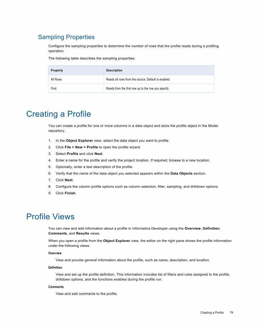
Sampling PropertiesConfigure the sampling properties to determine the number of rows that the profile reads during a profilingoperation.
The following table describes the sampling properties:
Property Description
All Rows Reads all rows from the source. Default is enabled.
First Reads from the first row up to the row you specify.
Creating a ProfileYou can create a profile for one or more columns in a data object and store the profile object in the Modelrepository.
1. In the Object Explorer view, select the data object you want to profile.
2. Click File > New > Profile to open the profile wizard.
3. Select Profile and click Next.
4. Enter a name for the profile and verify the project location. If required, browse to a new location.
5. Optionally, enter a text description of the profile.
6. Verify that the name of the data object you selected appears within the Data Objects section.
7. Click Next.
8. Configure the column profile options such as column selection, filter, sampling, and drilldown options.
9. Click Finish.
Profile ViewsYou can view and add information about a profile in Informatica Developer using the Overview, Definition,Comments, and Results views.
When you open a profile from the Object Explorer view, the editor on the right pane shows the profile informationunder the following views:
Overview
View and provide general information about the profile, such as name, description, and location.
Definition
View and set up the profile definition. This information includes list of filters and rules assigned to the profile,drilldown options, and the functions enabled during the profile run.
Comments
View and add comments to the profile.
Creating a Profile 79
Results
Shows the results of profile run.
Column Profile ResultsColumn profile analysis provides information about data quality by highlighting patterns and instances of non-conformance in data.
Column profiling analysis generates the following profile results:
¨ Percentage and count statistics for unique and null values
¨ Inferred datatypes
¨ The datatype that the data source declares for the data
¨ The maximum and minimum values
¨ The date and time of the most recent profile run
¨ Percentage and count statistics for each unique data element in a column
¨ Percentage and count statistics for each unique character pattern in a column
Column Value PropertiesColumn value properties show the values in the profiled columns and the frequency with which each value appears ineach column. The frequencies are shown as a number, a percentage, and a bar chart.
To view column value properties, select Values from the Show menu. Double-click a column value to drill-down to therows that contain the value.
The following table describes the properties for column values:
Property Description
Values List of all values for the column in the profile.
Frequency Number of times a value appears in a column.
Percent Number of times a value appears in a column, expressed as a percentage of all valuesin the column.
Chart Bar chart for the percentage.
Column Pattern PropertiesColumn pattern properties show the patterns of data in the profiled columns and the frequency with which the patternsappear in each column. The patterns are shown as a number, a percentage, and a bar chart.
To view pattern information, select Patterns from the Show menu. Double-click a pattern to drill-down to the rows thatcontain the pattern.
80 Chapter 5: Profiles
The following table describes the properties for column value patterns:
Property Description
Patterns Pattern for the selected column.
Frequency Number of times a pattern appears in a column.
Percent Number of times a pattern appears in a column, expressed as a percentage of all valuesin the column.
Chart Bar chart for the percentage.
Column Statistics PropertiesColumn statistics properties provide maximum and minimum lengths of values and first and last values.
To view statistical information, select Statistics from the Show menu.
The following table describes the column statistics properties:
Property Description
Maximum Length Length of the longest value in the column.
Minimum Length Length of the shortest value in the column.
Bottom Last five values in the column.
Top First five values in the column.
Note: The profile also displays average and standard deviation statistics for columns of type Integer.
Exporting Profile Results from Informatica DeveloperYou can export column values and column pattern data from profile results.
Export column values in Distinct Value Count format. Export pattern values in Domain Inference format.
1. In the Object Explorer view, select and open a profile.
2. Optionally, run the profile to update the profile results.
3. Select the Results view.
4. Select the column that contains the data for export.
5. Under Details, select Values or select Patterns and click the Export button.
The Export data to a file dialog box opens.
6. Accept or change the file name. The default name is [Profile_name]_[column_name]_DVC for column valuedata and [Profile_name]_[column_name]_DI for pattern data.
7. Select the type of data to export. You can select either Values for the selected column or Patterns for theselected column.
Exporting Profile Results from Informatica Developer 81
8. Under Save, choose Save on Client and click Browse to select a location and save the file locally in yourcomputer. By default, Informatica Developer writes the file to a location set in the Data Integration Serviceproperties of Informatica Administrator.
9. If you do not want to export field names as the first row, clear the Export field names as first row check box.
10. Click OK.
Synchronizing a Flat File Data ObjectYou can synchronize the changes to an external flat file data source with its data object in Informatica Developer. Usethe Synchronize Flat File wizard to synchronize the data objects.
1. In the Object Explorer view, select a flat file data object.
2. Right-click and select Synchronize.
The Synchronize Flat File Data Object wizard appears.
3. Verify the flat file path in the Select existing flat file field.
4. Click Next.
5. Optionally, select the code page, format, delimited format properties, and column properties.
6. Click Finish, and then click OK.
Synchronizing a Relational Data ObjectYou can synchronize external data source changes of a relational data source with its data object in InformaticaDeveloper. External data source changes include adding, changing, and removing columns, and changes to rules.
1. In the Object Explorer view, select a relational data object.
2. Right-click and select Synchronize.
A message prompts you to confirm the action.
3. To complete the synchronization process, click OK. Click Cancel to cancel the process.
If you click OK, a synchronization process status message appears.
4. When you see a Synchronization complete message, click OK.
The message displays a summary of the metadata changes made to the data object.
82 Chapter 5: Profiles
C H A P T E R 6
Logical View of DataThis chapter includes the following topics:
¨ Logical View of Data Overview, 83
¨ Developing a Logical View of Data, 84
¨ Logical Data Object Models, 84
¨ Logical Data Object Model Properties , 86
¨ Logical Data Objects, 92
¨ Logical Data Object Mappings, 93
Logical View of Data OverviewA logical view of data is a representation of data that resides in an enterprise. A logical view of data includes a logicaldata model, logical data objects, and logical data object mappings.
With a logical view of data, you can achieve the following goals:
¨ Use common data models across an enterprise so that you do not have to redefine data to meet different businessneeds. It also means if there is a change in data attributes, you can apply this change one time and use onemapping to make this change to all databases that use this data.
¨ Find relevant sources of data and present the data in a single view. Data resides in various places in an enterprise,such as relational databases and flat files. You can access all data sources and present the data in one view.
¨ Expose logical data as relational tables to promote reuse.
Logical Data Object Model ExampleCreate a logical data object model to describe the representation of logical entities in an enterprise. For example,create a logical data object model to present account data from disparate sources in a single view.
American Bank acquires California Bank. After the acquisition, American Bank has the following goals:
¨ Present data from both banks in a business intelligence report, such as a report on the top 10 customers.
¨ Consolidate data from both banks into a central data warehouse.
Traditionally, American Bank would consolidate the data into a central data warehouse in a developmentenvironment, verify the data, and move the data warehouse to a production environment. This process might takeseveral months or longer. The bank could then run business intelligence reports on the data warehouse in theproduction environment.
83
A developer at American Bank can use the Developer tool to create a model of customer, account, branch, and otherdata in the enterprise. The developer can link the relational sources of American Bank and California bank to a singleview of the customer. The developer can then make the data available for business intelligence reports beforecreating a central data warehouse.
Developing a Logical View of DataDevelop a logical view of data to represent how an enterprise accesses data and uses data.
Before you develop a logical view of data, you can define the physical data objects that you want to use in a logicaldata object mapping. You can also profile the physical data sources to analyze data quality.
1. Create or import a logical data model.
2. Optionally, add logical data objects to the logical data object model and define relationships between objects.
3. Create a logical data object mapping to read data from a logical data object or write data to a logical data object. Alogical data object mapping can contain transformation logic to transform the data.
4. View the output of the logical data object mapping.
Logical Data Object ModelsA logical data object model describes the structure and use of data in an enterprise. The model contains logical dataobjects and defines relationships between them.
Define a logical data object model to create a unified model of data in an enterprise. The data in an enterprise mightreside in multiple disparate source systems such as relational databases and flat files. A logical data object modelrepresents the data from the perspective of the business regardless of the source systems. Create a logical dataobject model to study data, describe data attributes, and define the relationships among attributes.
For example, customer account data from American Bank resides in an Oracle database, and customer account datafrom California Banks resides in an IBM DB2 database. You want to create a unified model of customer accounts thatdefines the relationship between customers and accounts. Create a logical data object model to define therelationship.
You can import a logical data object model from a modeling tool. You can also import a logical data object model froman XSD file that you created in a modeling tool. Or, you can manually create a logical data object model in theDeveloper tool.
You add a logical data object model to a project or folder and store it in the Model repository.
Creating a Logical Data Object ModelCreate a logical data object model to define the structure and use of data in an enterprise. When you create a logicaldata object model, you can add logical data objects. You associate a physical data object with each logical dataobject. The Developer tool creates a logical data object read mapping for each logical data object in the model.
1. Select a project or folder in the Object Explorer view.
2. Click File > New > Logical Data Object Model.
The New dialog box appears.
84 Chapter 6: Logical View of Data
3. Select Logical Data Object Model and click Next.
The New Logical Data Object Model dialog box appears.
4. Enter a name for the logical data object model.
5. To create logical data objects, click Next. To create an empty logical data object model, click Finish.
If you click Next, the Developer tool prompts you to add logical data objects to the model.
6. To create a logical data object, click the New button.
The Developer tool adds a logical data object to the list.
7. Enter a name in the Name column.
8. Optionally, click the Open button in the Data Object column to associate a physical data object with the logicaldata object.
The Select a Data Object dialog box appears.
9. Select a physical data object and click OK.
10. Repeat steps 6 through 10 to add logical data objects.
11. Click Finish.
The logical data object model opens in the editor.
Importing a Logical Data Object Model from a Modeling ToolYou can import a logical data object model from a modeling tool or an XSD file. Import a logical data object model touse an existing model of the structure and data in an enterprise.
1. Select the project or folder to which you want to import the logical data object model.
2. Click File > New > Logical Data Object Model.
The New Logical Data Object Model dialog box appears.
3. Select Logical Data Object Model from Data Model.
4. Click Next.
5. In the Model Type field, select the modeling tool from which you want to import the logical data object model.
6. Enter a name for the logical data object model.
7. Click Browse to select the location of the logical data object model.
8. Click Next.
9. Browse to the file that you want to import, select the file, and click Open.
10. Configure the import properties.
11. Click Next.
12. Add logical data objects to the logical data object model.
13. Click Finish.
The logical data objects appear in the editor.
Logical Data Object Models 85
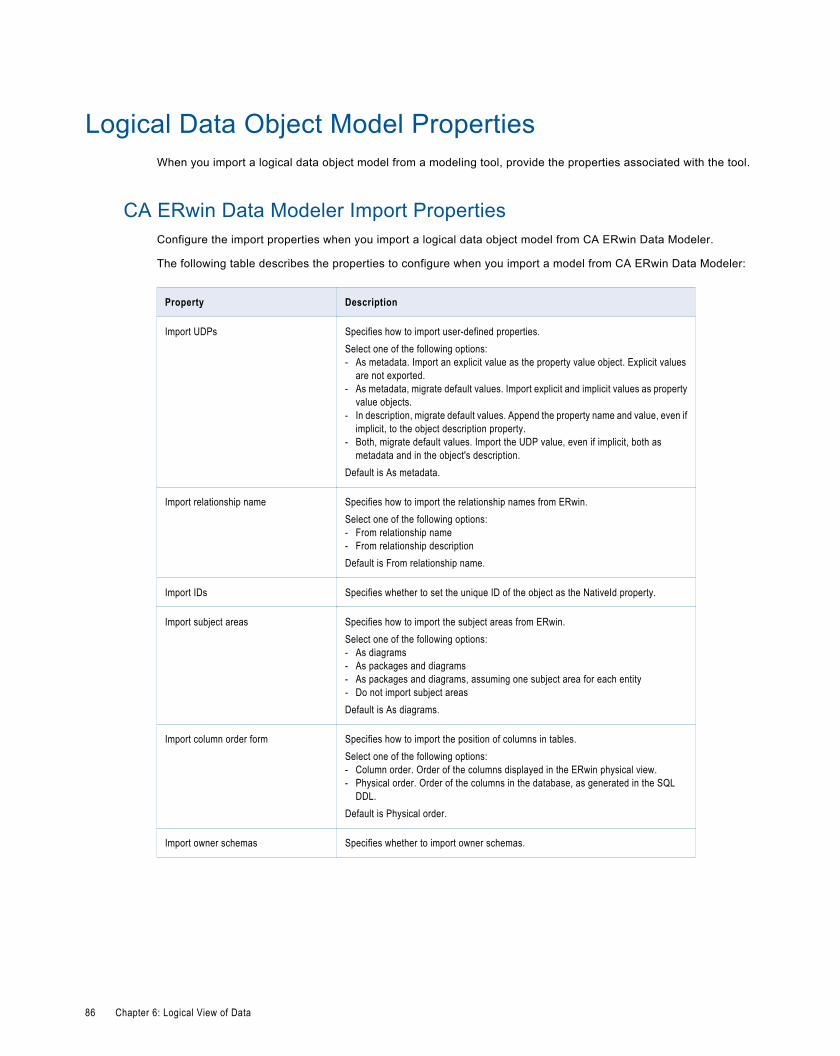
Logical Data Object Model PropertiesWhen you import a logical data object model from a modeling tool, provide the properties associated with the tool.
CA ERwin Data Modeler Import PropertiesConfigure the import properties when you import a logical data object model from CA ERwin Data Modeler.
The following table describes the properties to configure when you import a model from CA ERwin Data Modeler:
Property Description
Import UDPs Specifies how to import user-defined properties.Select one of the following options:- As metadata. Import an explicit value as the property value object. Explicit values
are not exported.- As metadata, migrate default values. Import explicit and implicit values as property
value objects.- In description, migrate default values. Append the property name and value, even if
implicit, to the object description property.- Both, migrate default values. Import the UDP value, even if implicit, both as
metadata and in the object's description.Default is As metadata.
Import relationship name Specifies how to import the relationship names from ERwin.Select one of the following options:- From relationship name- From relationship descriptionDefault is From relationship name.
Import IDs Specifies whether to set the unique ID of the object as the NativeId property.
Import subject areas Specifies how to import the subject areas from ERwin.Select one of the following options:- As diagrams- As packages and diagrams- As packages and diagrams, assuming one subject area for each entity- Do not import subject areasDefault is As diagrams.
Import column order form Specifies how to import the position of columns in tables.Select one of the following options:- Column order. Order of the columns displayed in the ERwin physical view.- Physical order. Order of the columns in the database, as generated in the SQL
DDL.Default is Physical order.
Import owner schemas Specifies whether to import owner schemas.
86 Chapter 6: Logical View of Data
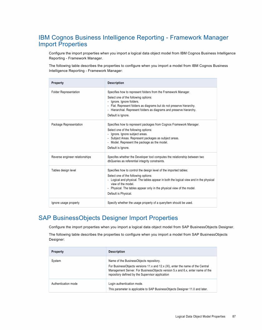
IBM Cognos Business Intelligence Reporting - Framework ManagerImport Properties
Configure the import properties when you import a logical data object model from IBM Cognos Business IntelligenceReporting - Framework Manager.
The following table describes the properties to configure when you import a model from IBM Cognos BusinessIntelligence Reporting - Framework Manager:
Property Description
Folder Representation Specifies how to represent folders from the Framework Manager.Select one of the following options:- Ignore. Ignore folders.- Flat. Represent folders as diagrams but do not preserve hierarchy.- Hierarchial. Represent folders as diagrams and preserve hierarchy.Default is Ignore.
Package Representation Specifies how to represent packages from Cognos Framework Manager.Select one of the following options:- Ignore. Ignore subject areas.- Subject Areas. Represent packages as subject areas.- Model. Represent the package as the model.Default is Ignore.
Reverse engineer relationships Specifes whether the Developer tool computes the relationship between twodbQueries as referential integrity constraints.
Tables design level Specifies how to control the design level of the imported tables:Select one of the following options:- Logical and physical. The tables appear in both the logical view and in the physical
view of the model.- Physical. The tables appear only in the physical view of the model.Default is Physical.
Ignore usage property Specify whether the usage property of a queryItem should be used.
SAP BusinessObjects Designer Import PropertiesConfigure the import properties when you import a logical data object model from SAP BusinessObjects Designer.
The following table describes the properties to configure when you import a model from SAP BusinessObjectsDesigner:
Property Description
System Name of the BusinessObjects repository.For BusinessObjects versions 11.x and 12.x (XI), enter the name of the CentralManagement Server. For BusinessObjects version 5.x and 6.x, enter name of therepository defined by the Supervisor application
Authentication mode Login authentication mode.This parameter is applicable to SAP BusinessObjects Designer 11.0 and later.
Logical Data Object Model Properties 87
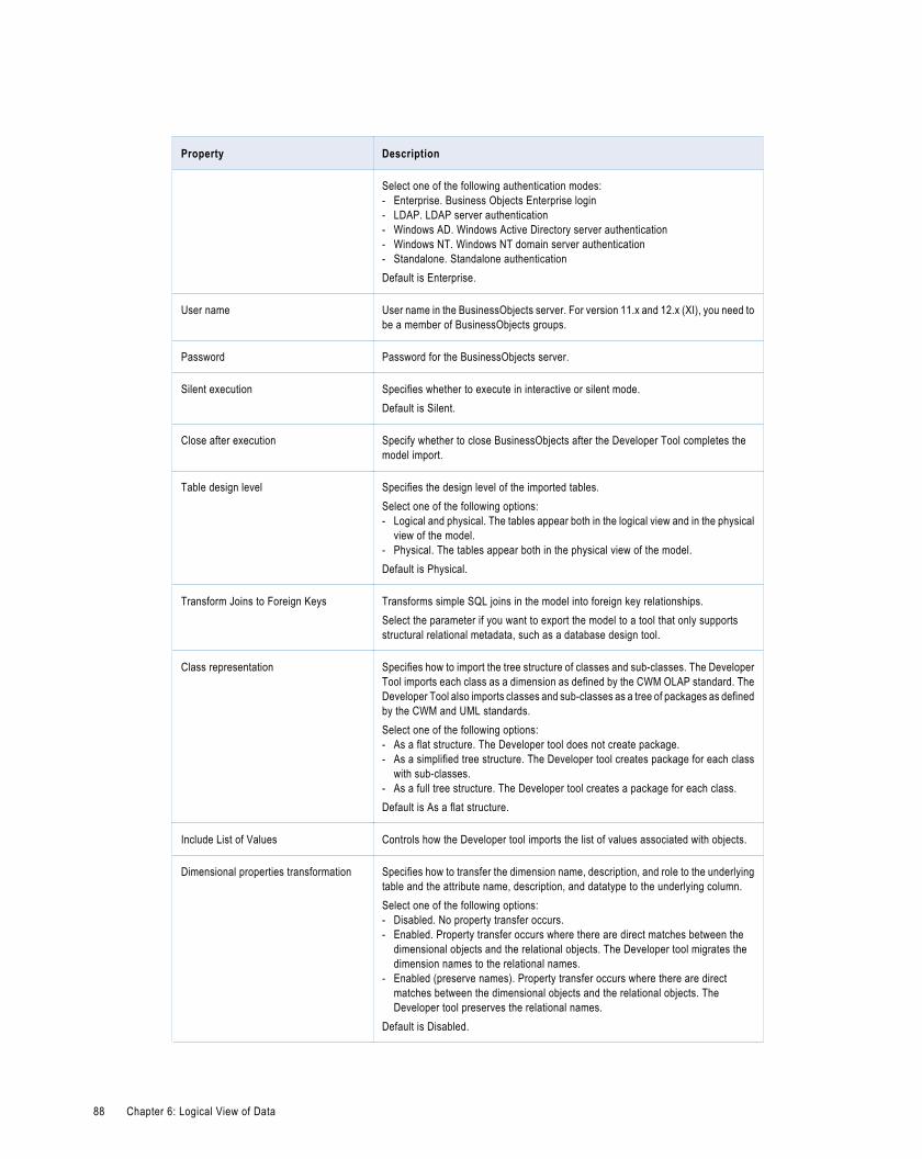
Property Description
Select one of the following authentication modes:- Enterprise. Business Objects Enterprise login- LDAP. LDAP server authentication- Windows AD. Windows Active Directory server authentication- Windows NT. Windows NT domain server authentication- Standalone. Standalone authenticationDefault is Enterprise.
User name User name in the BusinessObjects server. For version 11.x and 12.x (XI), you need tobe a member of BusinessObjects groups.
Password Password for the BusinessObjects server.
Silent execution Specifies whether to execute in interactive or silent mode.Default is Silent.
Close after execution Specify whether to close BusinessObjects after the Developer Tool completes themodel import.
Table design level Specifies the design level of the imported tables.Select one of the following options:- Logical and physical. The tables appear both in the logical view and in the physical
view of the model.- Physical. The tables appear both in the physical view of the model.Default is Physical.
Transform Joins to Foreign Keys Transforms simple SQL joins in the model into foreign key relationships.Select the parameter if you want to export the model to a tool that only supportsstructural relational metadata, such as a database design tool.
Class representation Specifies how to import the tree structure of classes and sub-classes. The DeveloperTool imports each class as a dimension as defined by the CWM OLAP standard. TheDeveloper Tool also imports classes and sub-classes as a tree of packages as definedby the CWM and UML standards.Select one of the following options:- As a flat structure. The Developer tool does not create package.- As a simplified tree structure. The Developer tool creates package for each class
with sub-classes.- As a full tree structure. The Developer tool creates a package for each class.Default is As a flat structure.
Include List of Values Controls how the Developer tool imports the list of values associated with objects.
Dimensional properties transformation Specifies how to transfer the dimension name, description, and role to the underlyingtable and the attribute name, description, and datatype to the underlying column.Select one of the following options:- Disabled. No property transfer occurs.- Enabled. Property transfer occurs where there are direct matches between the
dimensional objects and the relational objects. The Developer tool migrates thedimension names to the relational names.
- Enabled (preserve names). Property transfer occurs where there are directmatches between the dimensional objects and the relational objects. TheDeveloper tool preserves the relational names.
Default is Disabled.
88 Chapter 6: Logical View of Data
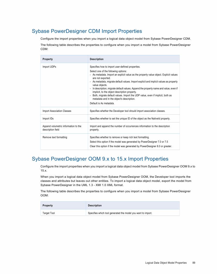
Sybase PowerDesigner CDM Import PropertiesConfigure the import properties when you import a logical data object model from Sybase PowerDesigner CDM.
The following table describes the properties to configure when you import a model from Sybase PowerDesignerCDM:
Property Description
Import UDPs Specifies how to import user-defined properties.Select one of the following options:- As metadata. Import an explicit value as the property value object. Explicit values
are not exported.- As metadata, migrate default values. Import explicit and implicit values as property
value objects.- In description, migrate default values. Append the property name and value, even if
implicit, to the object description property.- Both, migrate default values. Import the UDP value, even if implicit, both as
metadata and in the object's description.Default is As metadata.
Import Association Classes Specifies whether the Developer tool should import association classes.
Import IDs Specifies whether to set the unique ID of the object as the NativeId property.
Append volumetric information to thedescription field
Import and append the number of occurrences information to the descriptionproperty.
Remove text formatting Specifies whether to remove or keep rich text formatting.Select this option if the model was generated by PowerDesigner 7.0 or 7.5Clear this option if the model was generated by PowerDesigner 8.0 or greater.
Sybase PowerDesigner OOM 9.x to 15.x Import PropertiesConfigure the import properties when you import a logical data object model from Sybase PowerDesigner OOM 9.x to15.x.
When you import a logical data object model from Sybase PowerDesigner OOM, the Developer tool imports theclasses and attributes but leaves out other entities. To import a logical data object model, export the model fromSybase PowerDesigner in the UML 1.3 - XMI 1.0 XML format.
The following table describes the properties to configure when you import a model from Sybase PowerDesignerOOM:
Property Description
Target Tool Specifies which tool generated the model you want to import.
Logical Data Object Model Properties 89
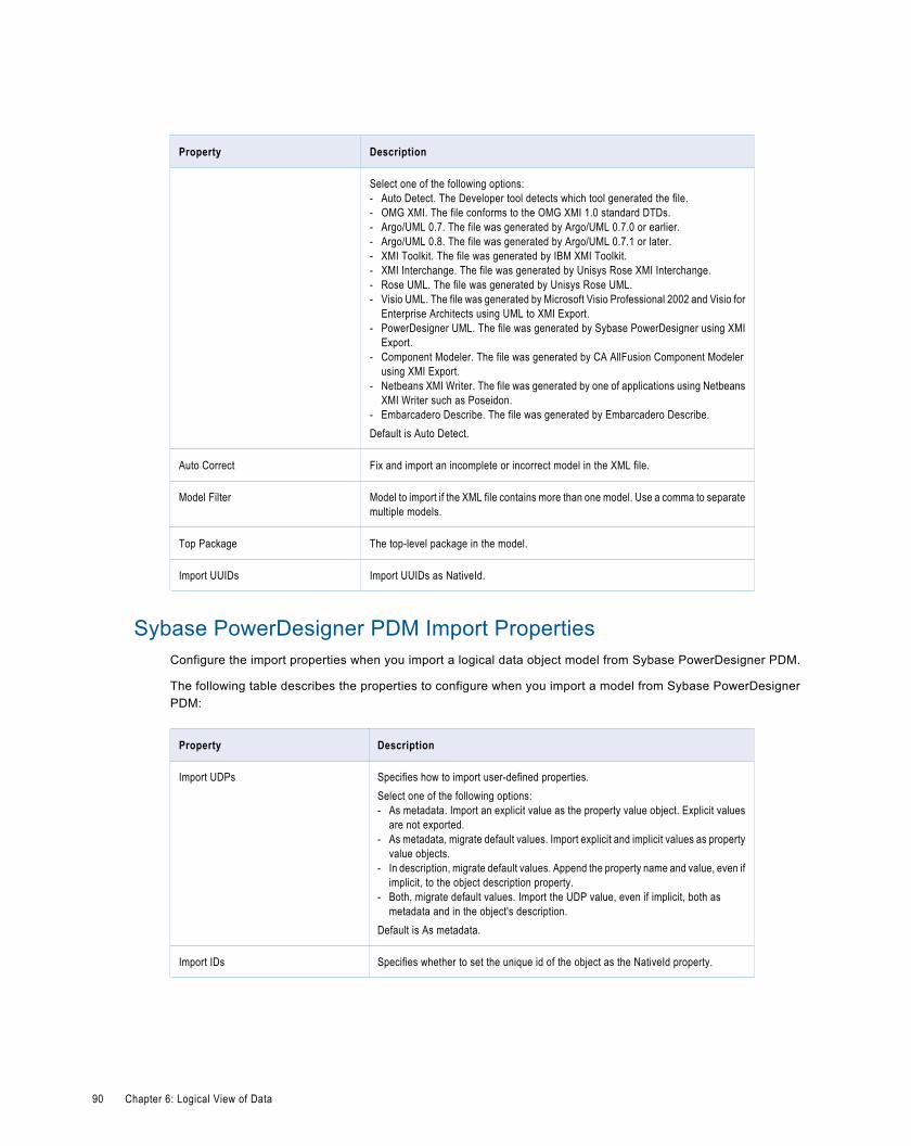
Property Description
Select one of the following options:- Auto Detect. The Developer tool detects which tool generated the file.- OMG XMI. The file conforms to the OMG XMI 1.0 standard DTDs.- Argo/UML 0.7. The file was generated by Argo/UML 0.7.0 or earlier.- Argo/UML 0.8. The file was generated by Argo/UML 0.7.1 or later.- XMI Toolkit. The file was generated by IBM XMI Toolkit.- XMI Interchange. The file was generated by Unisys Rose XMI Interchange.- Rose UML. The file was generated by Unisys Rose UML.- Visio UML. The file was generated by Microsoft Visio Professional 2002 and Visio for
Enterprise Architects using UML to XMI Export.- PowerDesigner UML. The file was generated by Sybase PowerDesigner using XMI
Export.- Component Modeler. The file was generated by CA AllFusion Component Modeler
using XMI Export.- Netbeans XMI Writer. The file was generated by one of applications using Netbeans
XMI Writer such as Poseidon.- Embarcadero Describe. The file was generated by Embarcadero Describe.Default is Auto Detect.
Auto Correct Fix and import an incomplete or incorrect model in the XML file.
Model Filter Model to import if the XML file contains more than one model. Use a comma to separatemultiple models.
Top Package The top-level package in the model.
Import UUIDs Import UUIDs as NativeId.
Sybase PowerDesigner PDM Import PropertiesConfigure the import properties when you import a logical data object model from Sybase PowerDesigner PDM.
The following table describes the properties to configure when you import a model from Sybase PowerDesignerPDM:
Property Description
Import UDPs Specifies how to import user-defined properties.Select one of the following options:- As metadata. Import an explicit value as the property value object. Explicit values
are not exported.- As metadata, migrate default values. Import explicit and implicit values as property
value objects.- In description, migrate default values. Append the property name and value, even if
implicit, to the object description property.- Both, migrate default values. Import the UDP value, even if implicit, both as
metadata and in the object's description.Default is As metadata.
Import IDs Specifies whether to set the unique id of the object as the NativeId property.
90 Chapter 6: Logical View of Data
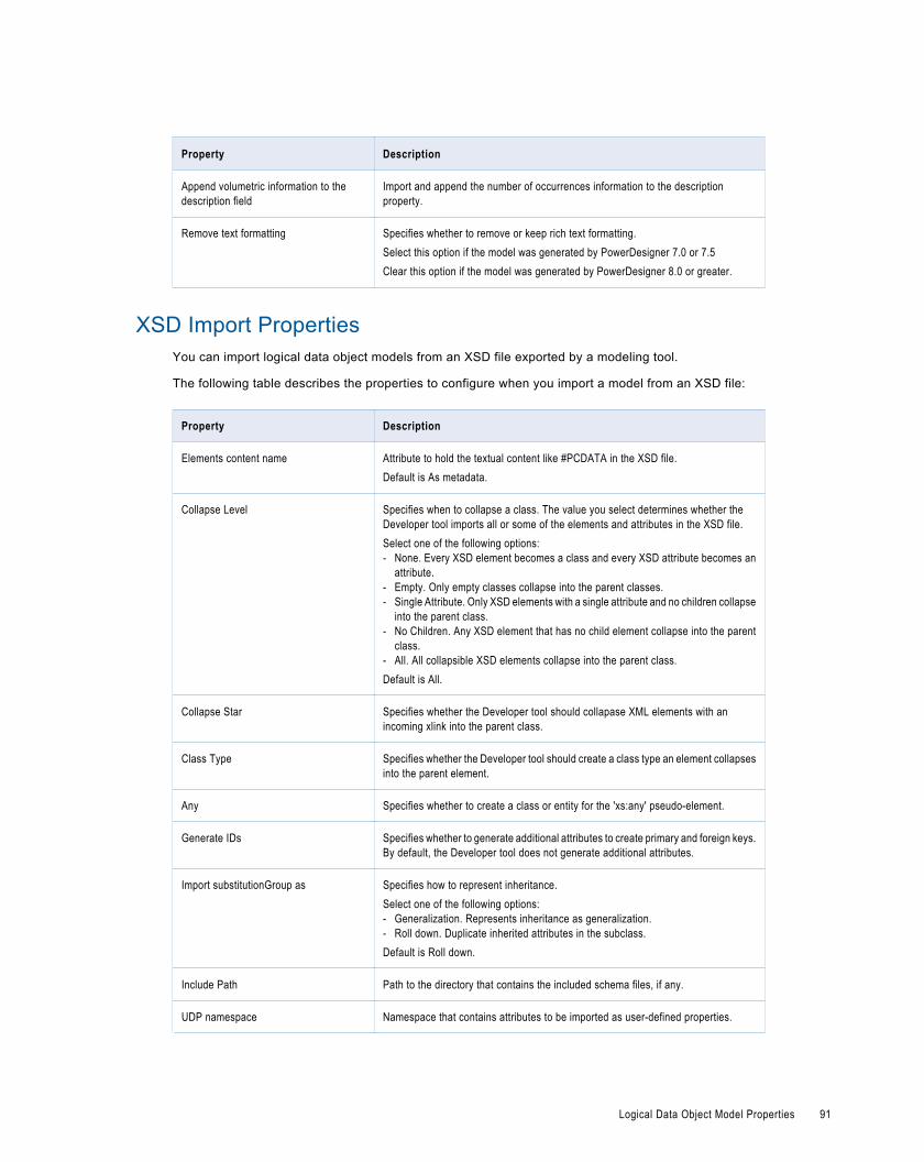
Property Description
Append volumetric information to thedescription field
Import and append the number of occurrences information to the descriptionproperty.
Remove text formatting Specifies whether to remove or keep rich text formatting.Select this option if the model was generated by PowerDesigner 7.0 or 7.5Clear this option if the model was generated by PowerDesigner 8.0 or greater.
XSD Import PropertiesYou can import logical data object models from an XSD file exported by a modeling tool.
The following table describes the properties to configure when you import a model from an XSD file:
Property Description
Elements content name Attribute to hold the textual content like #PCDATA in the XSD file.Default is As metadata.
Collapse Level Specifies when to collapse a class. The value you select determines whether theDeveloper tool imports all or some of the elements and attributes in the XSD file.Select one of the following options:- None. Every XSD element becomes a class and every XSD attribute becomes an
attribute.- Empty. Only empty classes collapse into the parent classes.- Single Attribute. Only XSD elements with a single attribute and no children collapse
into the parent class.- No Children. Any XSD element that has no child element collapse into the parent
class.- All. All collapsible XSD elements collapse into the parent class.Default is All.
Collapse Star Specifies whether the Developer tool should collapase XML elements with anincoming xlink into the parent class.
Class Type Specifies whether the Developer tool should create a class type an element collapsesinto the parent element.
Any Specifies whether to create a class or entity for the 'xs:any' pseudo-element.
Generate IDs Specifies whether to generate additional attributes to create primary and foreign keys.By default, the Developer tool does not generate additional attributes.
Import substitutionGroup as Specifies how to represent inheritance.Select one of the following options:- Generalization. Represents inheritance as generalization.- Roll down. Duplicate inherited attributes in the subclass.Default is Roll down.
Include Path Path to the directory that contains the included schema files, if any.
UDP namespace Namespace that contains attributes to be imported as user-defined properties.
Logical Data Object Model Properties 91
Logical Data ObjectsA logical data object is an object in a logical data object model that describes a logical entity in an enterprise. It hasattributes, keys, and it describes relationships between attributes.
You include logical data objects that relate to each other in a data object model. For example, the logical data objectsCustomer and Account appear in a logical data object model for a national bank. The logical data object modeldescribes the relationship between customers and accounts.
In the model, the logical data object Account includes the attribute Account_Number. Account_Number is a primarykey, because it uniquely identifies an account. Account has a relationship with the logical data object Customer,because the Customer data object needs to reference the account for each customer.
You can drag a physical data object into the logical data object model editor to create a logical data object. Or, you cancreate a logical data object and define the attributes and keys.
Logical Data Object PropertiesA logical data object contains properties that define the data object and its relationship to other logical data objects in alogical data object model.
A logical data object contains the following properties:
Name Description
General Name and description of the logical data object.
Attributes Comprise the structure of data in a logical data object.
Keys One or more attributes in a logical data object can be primarykeys or unique keys.
Relationships Associations between logical data objects.
Access Type of access for a logical data object and each attribute of thedata object.
Mappings Logical data object mappings associated with a logical dataobject.
Attribute RelationshipsA relationship is an association between primary or foreign key attributes of one or more logical data objects.
You can define the following types of relationship between attributes:Identifying
A relationship between two attributes where an attribute is identified through its association with anotherattribute.
For example, the relationship between the Branch_ID attribute of the logical data object Branch and theBranch_Location attribute of the logical data object Customer is identifying. This is because a branch ID is uniqueto a branch location.
Non-Identifying
A relationship between two attributes that identifies an attribute independently of the other attribute.
92 Chapter 6: Logical View of Data
For example, the relationship between the Account_Type attribute of the Account logical data object and theAccount_Number attribute of the Customer logical data object is non-identifying. This is because you can identifyan account type without having to associate it with an account number.
When you define relationships, the logical data object model indicates an identifying relationship as a solid linebetween attributes. It indicates a non-identifying relationship as a dotted line between attributes.
Creating a Logical Data ObjectYou can create a logical data object in a logical data object model to define a logical entity in an enterprise.
1. Click File > New > Logical Data Object.
2. Enter a logical data object name.
3. Select the logical data object model for the logical data object and click Finish.
The logical data object appears in the logical data object model editor.
4. Select the logical data object and click the Properties tab.
5. On the General tab, optionally edit the logical data object name and description.
6. On the Attributes tab, create attributes and specify their datatype and precision.
7. On the Keys tab, optionally specify primary and unique keys for the data object.
8. On the Relationships tab, optionally create relationships between logical data objects.
9. On the Access tab, optionally edit the type of access for the logical data object and each attribute in the dataobject.
Default is read only.
10. On the Mappings tab, optionally create a logical data object mapping.
Logical Data Object MappingsA logical data object mapping is a mapping that links a logical data object to one or more physical data objects. It caninclude transformation logic.
A logical data object mapping can be of the following types:
¨ Read
¨ Write
You can associate each logical data object with one logical data object read mapping or one logical data object writemapping.
Logical Data Object Read MappingsA logical data object read mapping contains one or more physical data objects as input and one logical data object asoutput. The mapping can contain transformation logic to transform the data.
It provides a way to access data without accessing the underlying data source. It also provides a way to have a singleview of data coming from more than one source.
For example, American Bank has a logical data object model for customer accounts. The logical data object modelcontains a Customers logical data object.
Logical Data Object Mappings 93
American Bank wants to view customer data from two relational databases in the Customers logical data object. Youcan use a logical data object read mapping to perform this task and view the output in the Data Viewer view.
Logical Data Object Write MappingsA logical data object write mapping contains a logical data object as input. It provides a way to write to targets from alogical data object.
The mapping can contain transformation logic to transform the data.
Creating a Logical Data Object MappingYou can create a logical data object mapping to link data from a physical data object to a logical data object andtransform the data.
1. In the Data Object Explorer view, select the logical data object model that you want to add the mapping to.
2. Click File > New > Other.
3. Select Informatica > Data Objects > Data Object Mapping and click Next.
4. Select the logical data object you want to include in the mapping.
5. Select the mapping type.
6. Optionally, edit the mapping name.
7. Click Finish.
The editor displays the logical data object as the mapping input or output, based on whether the mapping is a reador write mapping.
8. Drag one or more physical data objects to the mapping as read or write objects, based on whether the mapping isa read or write mapping.
9. Optionally, add transformations to the mapping.
10. Link ports in the mapping.
11. Right-click the mapping editor and click Validate to validate the mapping.
Validation errors appear on the Validation Log view.
12. Fix validation errors and validate the mapping again.
13. Optionally, click the Data Viewer view and run the mapping.
Results appear in the Output section.
94 Chapter 6: Logical View of Data
C H A P T E R 7
MappingsThis chapter includes the following topics:
¨ Mappings Overview, 95
¨ Developing a Mapping, 96
¨ Creating a Mapping, 96
¨ Mapping Objects, 97
¨ Linking Ports, 98
¨ Propagating Port Attributes, 100
¨ Mapping Validation, 102
¨ Running a Mapping, 103
¨ Segments, 104
Mappings OverviewA mapping is a set of inputs and outputs that represent the data flow between sources and targets. They can be linkedby transformation objects that define the rules for data transformation. The Data Integration Service uses theinstructions configured in the mapping to read, transform, and write data.
The type of input and output you include in a mapping determines the type of mapping. You can create the followingtypes of mappings in the Developer tool:
¨ Mapping with physical data objects as the input and output
¨ Logical data object mapping with a logical data object as the mapping input or output
Note: You can include a mapping with physical data objects as the input and output in a Mapping task in a workflow.You might want to run a mapping from a workflow so that you can run multiple mappings sequentially. Or, you candevelop a workflow that runs commands to perform steps before and after a mapping runs.
Object Dependency in a MappingA mapping is dependent on some objects that are stored as independent objects in the repository.
When object metadata changes, the Developer tool tracks the effects of these changes on mappings. Mappings mightbecome invalid even though you do not edit the mapping. When a mapping becomes invalid, the Data IntegrationService cannot run it.
95
The following objects are stored as independent objects in the repository:
¨ Logical data objects
¨ Physical data objects
¨ Reusable transformations
¨ Mapplets
A mapping is dependent on these objects.
Non-reusable transformations that you build within the mapping are stored as dependent repository objects within themapping.
Developing a MappingDevelop a mapping to read, transform, and write data according to your business needs.
1. Determine the type of mapping that you want to create.
2. Create input, output, and reusable objects that you want to use in the mapping. Create physical data objects orlogical data objects to use as mapping input or output.Create reusable transformations that you want to use. Ifyou want to use mapplets, you must create them also.
3. Create the mapping.
4. Add objects to the mapping. You must add input and output objects to the mapping. Optionally, addtransformations and mapplets.
5. Link ports between mapping objects to create a flow of data from sources to targets, through mapplets andtransformations that add, remove, or modify data along this flow.
6. Validate the mapping to identify errors.
7. Save the mapping to the Model repository.
After you develop the mapping, run it to see mapping output.
Creating a MappingCreate a mapping to move data between sources and targets and transform the data.
1. Select a project or folder in the Object Explorer view.
2. Click File > New > Mapping.
3. Optionally, enter a mapping name.
4. Click Finish.
An empty mapping appears in the editor.
96 Chapter 7: Mappings
Mapping ObjectsMapping objects determine the data flow between sources and targets.
Every mapping must contain the following objects:
¨ Input. Describes the characteristics of the mapping source.
¨ Output. Describes the characteristics of the mapping target.
A mapping can also contain the following components:
¨ Transformation. Modifies data before writing it to targets. Use different transformation objects to perform differentfunctions.
¨ Mapplet. A reusable object containing a set of transformations that you can use in multiple mappings.
When you add an object to a mapping, you configure the properties according to how you want the Data IntegrationService to transform the data. You also connect the mapping objects according to the way you want the DataIntegration Service to move the data. You connect the objects through ports.
The editor displays objects in the following ways:
¨ Iconized. Shows an icon of the object with the object name.
¨ Normal. Shows the columns and the input and output port indicators. You can connect objects that are in thenormal view.
Adding Objects to a MappingAdd objects to a mapping to determine the data flow between sources and targets.
1. Open the mapping.
2. Drag a physical data object to the editor and select Read to add the data object as a source.
3. Drag a physical data object to the editor and select Write to add the data object as a target.
4. To add a Lookup transformation, drag a flat file data object, logical data object, or relational data object to theeditor and select Lookup.
5. To add a reusable transformation, drag the transformation from the Transformations folder in the ObjectExplorer view to the editor.
Repeat this step for each reusable transformation you want to add.
6. To add a non-reusable transformation, select the transformation on the Transformation palette and drag it to theeditor.
Repeat this step for each non-reusable transformation you want to add.
7. Configure ports and properties for each non-reusable transformation.
8. Optionally, drag a mapplet to the editor.
One to One LinksLink one port in an input object or transformation to one port in an output object or transformation.
Mapping Objects 97
One to Many LinksWhen you want to use the same data for different purposes, you can link the port providing that data to multiple ports inthe mapping.
You can create a one to many link in the following ways:
¨ Link one port to multiple transformations or output objects.
¨ Link multiple ports in one transformation to multiple transformations or output objects.
For example, you want to use salary information to calculate the average salary in a bank branch through theAggregator transformation. You can use the same information in an Expression transformation configured to calculatethe monthly pay of each employee.
Linking PortsAfter you add and configure input, output, transformation, and mapplet objects in a mapping, complete the mapping bylinking ports between mapping objects.
Data passes into and out of a transformation through the following ports:
¨ Input ports. Receive data.
¨ Output ports. Pass data.
¨ Input/output ports. Receive data and pass it unchanged.
Every input object, output object, mapplet, and transformation contains a collection of ports. Each port represents acolumn of data:
¨ Input objects provide data, so they contain only output ports.
¨ Output objects receive data, so they contain only input ports.
¨ Mapplets contain only input ports and output ports.
¨ Transformations contain a mix of input, output, and input/output ports, depending on the transformation and itsapplication.
To connect ports, you create a link between ports in different mapping objects. The Developer tool creates theconnection only when the connection meets link validation and concatenation requirements.
You can leave ports unconnected. The Data Integration Service ignores unconnected ports.
When you link ports between input objects, transformations, mapplets, and output objects, you can create thefollowing types of link:
¨ One to one
¨ One to many
You can manually link ports or link ports automatically.
Manually Linking PortsYou can manually link one port or multiple ports.
Drag a port from an input object or transformation to the port of an output object or transformation.
Use the Ctrl or Shift key to select multiple ports to link to another transformation or output object. The Developer toollinks the ports, beginning with the top pair. It links all ports that meet the validation requirements.
When you drag a port into an empty port, the Developer tool copies the port and creates a connection.
98 Chapter 7: Mappings
Automatically Linking PortsWhen you link ports automatically, you can link by position or by name.
When you link ports automatically by name, you can specify a prefix or suffix by which to link the ports. Use prefixes orsuffixes to indicate where ports occur in a mapping.
Linking Ports by NameWhen you link ports by name, the Developer tool adds links between input and output ports that have the same name.Link by name when you use the same port names across transformations.
You can link ports based on prefixes and suffixes that you define. Use prefixes or suffixes to indicate where portsoccur in a mapping. Link by name and prefix or suffix when you use prefixes or suffixes in port names to distinguishwhere they occur in the mapping or mapplet.
Linking by name is not case sensitive.
1. Click Mapping > Auto Link.
The Auto Link dialog box appears.
2. Select an object in the From window to link from.
3. Select an object in the To window to link to.
4. Select Name.
5. Optionally, click Advanced to link ports based on prefixes or suffixes.
6. Click OK.
Linking Ports by PositionWhen you link by position, the Developer tool links the first output port to the first input port, the second output port tothe second input port, and so forth. Link by position when you create transformations with related ports in the sameorder.
1. Click Mapping > Auto Link.
The Auto Link dialog box appears.
2. Select an object in the From window to link from.
3. Select an object in the To window to link to.
4. Select Position and click OK.
The Developer tool links the first output port to the first input port, the second output port to the second input port,and so forth.
Rules and Guidelines for Linking PortsCertain rules and guidelines apply when you link ports.
Use the following rules and guidelines when you connect mapping objects:
¨ If the Developer tool detects an error when you try to link ports between two mapping objects, it displays a symbolindicating that you cannot link the ports.
¨ Follow the logic of data flow in the mapping. You can link the following types of port:
- The receiving port must be an input or input/output port.
- The originating port must be an output or input/output port.
Linking Ports 99
- You cannot link input ports to input ports or output ports to output ports.
¨ You must link at least one port of an input group to an upstream transformation.
¨ You must link at least one port of an output group to a downstream transformation.
¨ You can link ports from one active transformation or one output group of an active transformation to an input groupof another transformation.
¨ You cannot connect an active transformation and a passive transformation to the same downstreamtransformation or transformation input group.
¨ You cannot connect more than one active transformation to the same downstream transformation ortransformation input group.
¨ You can connect any number of passive transformations to the same downstream transformation, transformationinput group, or target.
¨ You can link ports from two output groups in the same transformation to one Joiner transformation configured forsorted data if the data from both output groups is sorted.
¨ You can only link ports with compatible datatypes. The Developer tool verifies that it can map between the twodatatypes before linking them. The Data Integration Service cannot transform data between ports withincompatible datatypes.
¨ The Developer tool marks some mappings invalid if the mapping violates data flow validation.
Propagating Port AttributesPropagate port attributes to pass changed attributes to a port throughout a mapping.
1. In the mapping editor, select a port in a transformation.
2. Click Mapping > Propagate Attributes.
The Propagate Attributes dialog box appears.
3. Select a direction to propagate attributes.
4. Select the attributes you want to propagate.
5. Optionally, preview the results.
6. Click Apply.
The Developer tool propagates the port attributes.
Dependency TypesWhen you propagate port attributes, the Developer tool updates dependencies.
The Developer tool can update the following dependencies:
¨ Link path dependencies
¨ Implicit dependencies
Link Path DependenciesA link path dependency is a dependency between a propagated port and the ports in its link path.
100 Chapter 7: Mappings
When you propagate dependencies in a link path, the Developer tool updates all the input and input/output ports in itsforward link path and all the output and input/output ports in its backward link path. The Developer tool performs thefollowing updates:
¨ Updates the port name, datatype, precision, scale, and description for all ports in the link path of the propagatedport.
¨ Updates all expressions or conditions that reference the propagated port with the changed port name.
¨ Updates the associated port property in a dynamic Lookup transformation if the associated port name changes.
Implicit DependenciesAn implicit dependency is a dependency within a transformation between two ports based on an expression orcondition.
You can propagate datatype, precision, scale, and description to ports with implicit dependencies. You can also parseconditions and expressions to identify the implicit dependencies of the propagated port. All ports with implicitdependencies are output or input/output ports.
When you include conditions, the Developer tool updates the following dependencies:
¨ Link path dependencies
¨ Output ports used in the same lookup condition as the propagated port
¨ Associated ports in dynamic Lookup transformations that are associated with the propagated port
¨ Master ports used in the same join condition as the detail port
When you include expressions, the Developer tool updates the following dependencies:
¨ Link path dependencies
¨ Output ports containing an expression that uses the propagated port
The Developer tool does not propagate to implicit dependencies within the same transformation. You must propagatethe changed attributes from another transformation. For example, when you change the datatype of a port that is usedin a lookup condition and propagate that change from the Lookup transformation, the Developer tool does notpropagate the change to the other port dependent on the condition in the same Lookup transformation.
Propagated Port Attributes by TransformationThe Developer tool propagates dependencies and attributes for each transformation.
The following table describes the dependencies and attributes the Developer tool propagates for eachtransformation:
Transformation Dependency Propagated Attributes
Aggregator - Ports in link path- Expression- Implicit dependencies
- Port name, datatype, precision, scale,description
- Port name- Datatype, precision, scale
Expression - Ports in link path- Expression- Implicit dependencies
- Port name, datatype, precision, scale,description
- Port name- Datatype, precision, scale
Propagating Port Attributes 101
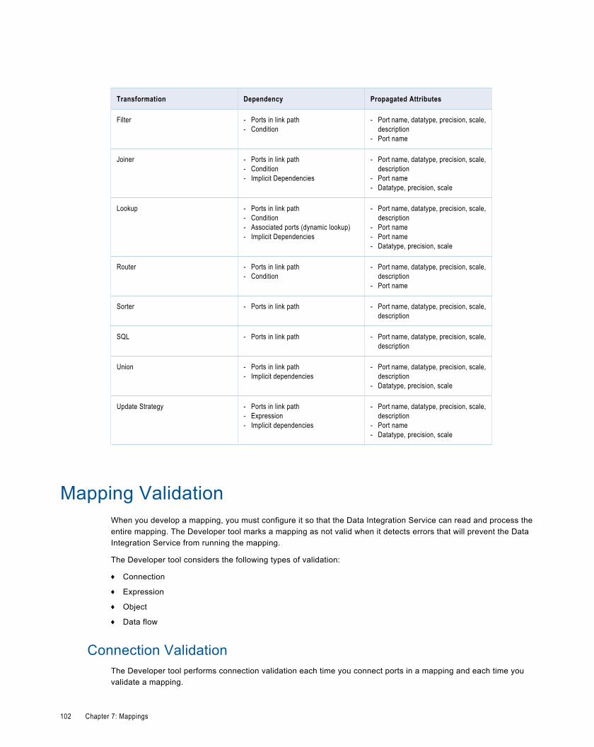
Transformation Dependency Propagated Attributes
Filter - Ports in link path- Condition
- Port name, datatype, precision, scale,description
- Port name
Joiner - Ports in link path- Condition- Implicit Dependencies
- Port name, datatype, precision, scale,description
- Port name- Datatype, precision, scale
Lookup - Ports in link path- Condition- Associated ports (dynamic lookup)- Implicit Dependencies
- Port name, datatype, precision, scale,description
- Port name- Port name- Datatype, precision, scale
Router - Ports in link path- Condition
- Port name, datatype, precision, scale,description
- Port name
Sorter - Ports in link path - Port name, datatype, precision, scale,description
SQL - Ports in link path - Port name, datatype, precision, scale,description
Union - Ports in link path- Implicit dependencies
- Port name, datatype, precision, scale,description
- Datatype, precision, scale
Update Strategy - Ports in link path- Expression- Implicit dependencies
- Port name, datatype, precision, scale,description
- Port name- Datatype, precision, scale
Mapping ValidationWhen you develop a mapping, you must configure it so that the Data Integration Service can read and process theentire mapping. The Developer tool marks a mapping as not valid when it detects errors that will prevent the DataIntegration Service from running the mapping.
The Developer tool considers the following types of validation:
¨ Connection
¨ Expression
¨ Object
¨ Data flow
Connection ValidationThe Developer tool performs connection validation each time you connect ports in a mapping and each time youvalidate a mapping.
102 Chapter 7: Mappings
When you connect ports, the Developer tool verifies that you make valid connections. When you validate a mapping,the Developer tool verifies that the connections are valid and that all required ports are connected. The Developer toolmakes the following connection validations:
¨ At least one input object and one output object are connected.
¨ At least one mapplet input port and output port is connected to the mapping.
¨ Datatypes between ports are compatible. If you change a port datatype to one that is incompatible with the port it isconnected to, the Developer tool generates an error and invalidates the mapping. You can however, change thedatatype if it remains compatible with the connected ports, such as Char and Varchar.
Expression ValidationYou can validate an expression in a transformation while you are developing a mapping. If you did not correct theerrors, error messages appear in the Validation Log view when you validate the mapping.
If you delete input ports used in an expression, the Developer tool marks the mapping as invalid.
Object ValidationWhen you validate a mapping, the Developer tool verifies that the definitions of the independent objects, such as Inputtransformations or mapplets, match the instance in the mapping.
If any object changes while you configure the mapping, the mapping might contain errors. If any object changes whileyou are not configuring the mapping, the Developer tool tracks the effects of these changes on the mappings.
Validating a MappingValidate a mapping to ensure that the Data Integration Service can read and process the entire mapping.
1. Click Edit > Validate.
Errors appear in the Validation Log view.
2. Fix errors and validate the mapping again.
Running a MappingRun a mapping to move output from sources to targets and transform data.
Before you can run a mapping, you need to configure a Data Integration Service in the Administrator tool. You alsoneed to select a default Data Integration Service. If you have not selected a default Data Integration Service, theDeveloper tool prompts you to select one.
u Right-click an empty area in the editor and click Run Mapping.
The Data Integration Service runs the mapping and writes the output to the target.
Running a Mapping 103
SegmentsA segment consists of one or more objects in a mapping, mapplet, or rule. A segment can include a source, target,transformation, or mapplet.
You can copy segments. Consider the following rules and guidelines when you copy a segment:
¨ You can copy segments across folders or projects.
¨ The Developer tool reuses dependencies when possible. Otherwise, it copies dependencies.
¨ If a mapping, mapplet, or rule includes parameters and you copy a transformation that refers to the parameter, thetransformation in the target object uses a default value for the parameter.
¨ You cannot copy input transformations and output transformations.
¨ After you paste a segment, you cannot undo previous actions.
104 Chapter 7: Mappings
C H A P T E R 8
Performance TuningThis chapter includes the following topics:
¨ Optimizer Levels, 105
¨ Optimization Methods Overview, 106
¨ Full Optimization and Memory Allocation, 108
¨ Setting the Optimizer Level for a Developer Tool Mapping, 109
¨ Setting the Optimizer Level for a Deployed Mapping, 109
Optimizer LevelsThe Data Integration Service attempts to apply different optimizer methods based on the optimizer level that youconfigure for the object.
You can choose one of the following optimizer levels:None
The Data Integration Service does not apply any optimization.
Minimal
The Data Integration Service applies the early projection optimization method.
Normal
The Data Integration Service applies the early projection, early selection, push-into, pushdown, and predicateoptimization methods. Normal is the default optimization level.
Full
The Data Integration Service applies the cost-based, early projection, early selection, predicate, push-into,pushdown, and semi-join optimization methods.
105
RELATED TOPICS:¨ “Pushdown Optimization Overview” on page 110
Optimization Methods OverviewThe Data Integration Service applies optimization methods to reduce the number of rows to process in the mapping.You can configure the optimizer level for the mapping to limit which optimization methods the Data Integration Serviceapplies.
The Data Integration Service can apply the following optimization methods:
¨ Pushdown optimization
¨ Early projection
¨ Early selection
¨ Push-into optimization
¨ Predicate optimization
¨ Cost-based
¨ Semi-join
The Data Integration Service can apply multiple optimization methods to a mapping at the same time. For example,the Data Integration Service applies the early projection, predicate optimization, and early selection or push-intooptimization methods when you select the normal optimizer level.
Early Projection Optimization MethodWhen the Data Integration Service applies the early projection optimization method, it identifies unused ports andremoves the links between those ports.
Early projection improves performance by reducing the amount of data that the Data Integration Service moves acrosstransformations. When the Data Integration Service processes a mapping, it moves the data from all connected portsin a mapping from one transformation to another. In large, complex mappings, or in mappings that use nestedmapplets, some ports might not supply data to the target. The Data Integration Service identifies the ports that do notsupply data to the target. After the Data Integration Service identifies unused ports, it removes the links between allunused ports from the mapping.
The Data Integration Service does not remove all links. For example, it does not remove the following links:
¨ Links connected to a Custom transformation
¨ Links connected to transformations that call an ABORT() or ERROR() function, send email, or call a storedprocedure
If the Data Integration Service determines that all ports in a transformation are unused, it removes all transformationlinks except the link to the port with the least data. The Data Integration Service does not remove the unusedtransformation from the mapping.
The Developer tool enables this optimization method by default.
Early Selection Optimization MethodWhen the Data Integration Service applies the early selection optimization method, it splits, moves, or removes theFilter transformations in a mapping. It moves filters up the mapping closer to the source.
106 Chapter 8: Performance Tuning
The Data Integration Service might split a Filter transformation if the filter condition is a conjunction. For example, theData Integration Service might split the filter condition "A>100 AND B<50" into two simpler conditions, "A>100" and"B<50." When the Data Integration Service splits a filter, it moves the simplified filters up the mapping pipeline, closerto the source. The Data Integration Service moves the filters up the pipeline separately when it splits the filter.
The Developer tool enables the early selection optimization method by default when you choose a normal or fulloptimizer level. The Data Integration Service does not enable early selection if a transformation that appears beforethe Filter transformation has side effects. You can configure the SQL transformation, Web Service Consumertransformation, and Java transformation for early selection optimization, however the Developer tool cannotdetermine if the transformations have side effects.
You can disable early selection if the optimization does not increase performance.
Predicate Optimization MethodWhen the Data Integration Service applies the predicate optimization method, it examines the predicate expressionsthat a mapping generates. It determines whether it can simpliify or rewrite the expressions to increase mappingperformance.
When the Data Integration Service runs a mapping, it generates queries against the mapping sources and performsoperations on the query results based on the mapping logic and the transformations within the mapping. The queriesand operations often include predicate expressions. Predicate expressions represent the conditions that the datamust satisfy. The filter and join conditions in Filter and Joiner transformations are examples of predicateexpressions.
With the predicate optimization method, the Data Integration Service also attempts to apply predicate expressions asearly as possible in the mapping to improve mapping performance.
The Data Integration Service infers relationships from by existing predicate expressions and creates new predicateexpressions. For example, a mapping contains a Joiner transformation with the join condition "A=B" and a Filtertransformation with the filter condition "A>5." The Data Integration Service might be able to add "B>5" to the joincondition.
The Data Integration Service applies the predicate optimization method with the early selection optimization methodwhen it can apply both methods to a mapping. For example, when the Data Integration Service creates new filterconditions through the predicate optimization method, it also attempts to move them upstream in the mapping throughthe early selection method. Applying both optimization methods improves mapping performance when compared toapplying either method alone.
The Data Integration Service applies the predicate optimization method if the application increases performance. TheData Integration Service does not apply this method if the application changes the mapping results or it decreases themapping performance.
Cost-Based Optimization MethodWith cost-based optimization, the Data Integration Service evaluates a mapping, generates semantically equivalentmappings, and runs the mapping with the best performance. Cost-based optimization reduces run time for mappingsthat perform adjacent, unsorted, inner-join operations.
Semantically equivalent mappings are mappings that perform identical functions and produce the same results. Togenerate semantically equivalent mappings, the Data Integration Service divides the original mapping into fragments.The Data Integration Service then determines which mapping fragments it can optimize.
The Data Integration Service optimizes each fragment that it can optimize. During optimization, the Data IntegrationService might add, remove, or reorder transformations within a fragment. The Data Integration Service verifies thatthe optimized fragments produce the same results as the original fragments and forms alternate mappings that usethe optimized fragments.
Optimization Methods Overview 107
The Data Integration Service generates all or almost all of the mappings that are semantically equivalent to theoriginal mapping. It uses profiling or database statistics to compute the cost for the original mapping and eachalternate mapping. Then, it identifies the mapping that runs most quickly. The Data Integration Service performs avalidation check on the best alternate mapping to ensure that it is valid and produces the same results as the originalmapping.
The Data Integration Service caches the best alternate mapping in memory. When you run a mapping, the DataIntegration Service retrieves the alternate mapping and runs it instead of the original mapping.
Semi-Join Optimization MethodThe semi-join optimization method attempts to reduce the amount of data extracted from the source by modifying joinoperations in the mapping.
The Data Integration Service applies this method to a Joiner transformation when one input group has many morerows than the other and when the larger group has many rows with no match in the smaller group based on the joincondition. The Data Integration Service attempts to decrease the size of the data set of one join operand by readingthe rows from the smaller group, finding the matching rows in the larger group, and then performing the join operation.Decreasing the size of the data set improves mapping performance because the Data Integration Service no longerreads unnecessary rows from the larger group source. The Data Integration Service moves the join condition to thelarger group source and reads only the rows that match the smaller group.
Before applying this optimization method, the Data Integration Service performs analyses to determine whether semi-join optimization is possible and likely to be worthwhile. If the analyses determine that this method is likely to increaseperformance, the Data Integration Service applies it to the mapping. The Data Integration Service then reanalyzes themapping to determine whether there are additional opportunities for semi-join optimization. It performs additionaloptimizations if appropriate. The Data Integration Service does not apply semi-join optimization unless the analysesdetermine that there is a high probability for improved performance.
The Developer tool does not enable this method by default.
Full Optimization and Memory AllocationWhen you configure full optimization for a mapping, you might need to increase the available memory to avoidmapping failure.
When a mapping contains Joiner transformations and other transformations that use caching, the mapping might runsuccessfully at the default optimization level. If you change the optimization level to full optimization and the DataIntegration Service performs semi-join optimization, the Data Integration Service requires more memory to sort thedata. The mapping might fail if you do not increase the maximum session size.
Change the Maximum Session Size in the Execution Options for the Data Integration Service process. Increase theMaximum Session Size by 50MB to 100MB.
108 Chapter 8: Performance Tuning
Setting the Optimizer Level for a Developer ToolMapping
When you run a mapping through the Run menu or mapping editor, the Developer tool runs the mapping with thenormal optimizer level. To run the mapping with a different optimizer level, run the mapping from the RunConfigurations dialog box.
1. Open the mapping.
2. Select Run > Open Run Dialog.
The Run Configurations dialog box appears.
3. Select a mapping configuration that contains the optimizer level you want to apply or create a mappingconfiguration.
4. Click the Advanced tab.
5. Change the optimizer level, if necessary.
6. Click Apply.
7. Click Run to run the mapping.
The Developer tool runs the mapping with the optimizer level in the selected mapping configuration.
Setting the Optimizer Level for a Deployed MappingSet the optimizer level for a mapping you run from the command line by changing the mapping deployment propertiesin the application.
The mapping must be in an application.
1. Open the application that contains the mapping.
2. Click the Advanced tab.
3. Select the optimizer level.
4. Save the application.
After you change the optimizer level, you must redeploy the application.
Setting the Optimizer Level for a Developer Tool Mapping 109
C H A P T E R 9
Pushdown OptimizationThis chapter includes the following topics:
¨ Pushdown Optimization Overview, 110
¨ Pushdown Optimization to Sources, 111
¨ Pushdown Optimization Expressions, 112
¨ Comparing the Output of the Data Integration Service and Sources, 116
Pushdown Optimization OverviewPushdown optimization causes the Data Integration Service to push transformation logic to the source database. TheData Integration Service translates the transformation logic into SQL queries and sends the SQL queries to thedatabase. The source database executes the SQL queries to process the transformations.
Pushdown optimization improves the performance of mappings when the source database can processtransformation logic faster than the Data Integration Service. The Data Integration Service also reads less data fromthe source.
The amount of transformation logic that the Data Integration Service pushes to the source database depends on thedatabase, the transformation logic, and the mapping configuration. The Data Integration Service processes alltransformation logic that it cannot push to a database.
The Data Integration Service can push the following transformation logic to the source database:
¨ Expression transformation logic
¨ Filter transformation logic
¨ Joiner transformation logic. The sources must be in the same database management system and must useidentical connections.
The Data Integration Service cannot push transformation logic after a source in the following circumstances:
¨ The Data Integration Service cannot push any transformation logic if the source is a customized data object thatcontains a custom SQL query.
¨ The Data Integration Service cannot push any transformation logic if the source contains a column with a binarydatatype.
¨ The Data Integration Service cannot push Expression or Joiner transformation logic if the source is a customizeddata object that contains a filter condition or user-defined join.
The Data Integration Service applies pushdown optimization to a mapping when you select the normal or full optimizerlevel. When you select the normal optimizer level, the Data Integration Service applies pushdown optimization after it
110
applies all other optimization methods. If you select the full optimizer level, the Data Integration Service appliespushdown optimization before semi-join optimization, but after all of the other optimization methods.
When you apply pushdown optimization, the Data Integration Service analyzes the optimized mapping from thesource to the target or until it reaches a downstream transformation that it cannot push to the source database. TheData Integration Service generates and executes a SELECT statement based on the transformation logic for eachtransformation that it can push to the database. Then, it reads the results of this SQL query and processes theremaining transformations in the mapping.
RELATED TOPICS:¨ “Optimizer Levels” on page 105
Pushdown Optimization to SourcesThe Data Integration Service can push transformation logic to different sources. The type of logic that the DataIntegration Service pushes depends on the source type. The Data Integration Service can push Expression, Filter,and Joiner transformation logic to some sources. It can push Filter transformation logic to other sources.
The Data Integration Service can push transformation logic to the following types of sources:
¨ Sources that use native database drivers
¨ Sources that use ODBC drivers
Pushdown Optimization to Native SourcesWhen the Data Integration Service pushes transformation logic to relational sources using the native drivers, the DataIntegration Service generates SQL statements that use the native database SQL.
The Data Integration Service can push Expression, Filter, and Joiner transformation logic to the following nativesources:
¨ IBM DB2 for Linux, UNIX, and Windows ("DB2 for LUW")
¨ Microsoft SQL ServerThe Data Integration Service can use a native connection to Microsoft SQL Server when the Data IntegrationService runs on Windows.
¨ Oracle
Pushdown Optimization to ODBC SourcesThe Data Integration Service can push Expression, Filter, and Joiner transformation logic to databases that useODBC drivers.
When you use ODBC to connect to a source, the Data Integration Service can generate SQL statements using ANSISQL or native database SQL. The Data Integration Service can push more transformation logic to the source when itgenerates SQL statements using the native database SQL. The source can process native database SQL faster thanit can process ANSI SQL.
You can specify the ODBC provider in the ODBC connection object. When the ODBC provider is database specific,the Data Integration Service can generates SQL statements using native database SQL. When the ODBC provider isOther, the Data Integration Service generates SQL statements using ANSI SQL.
Pushdown Optimization to Sources 111
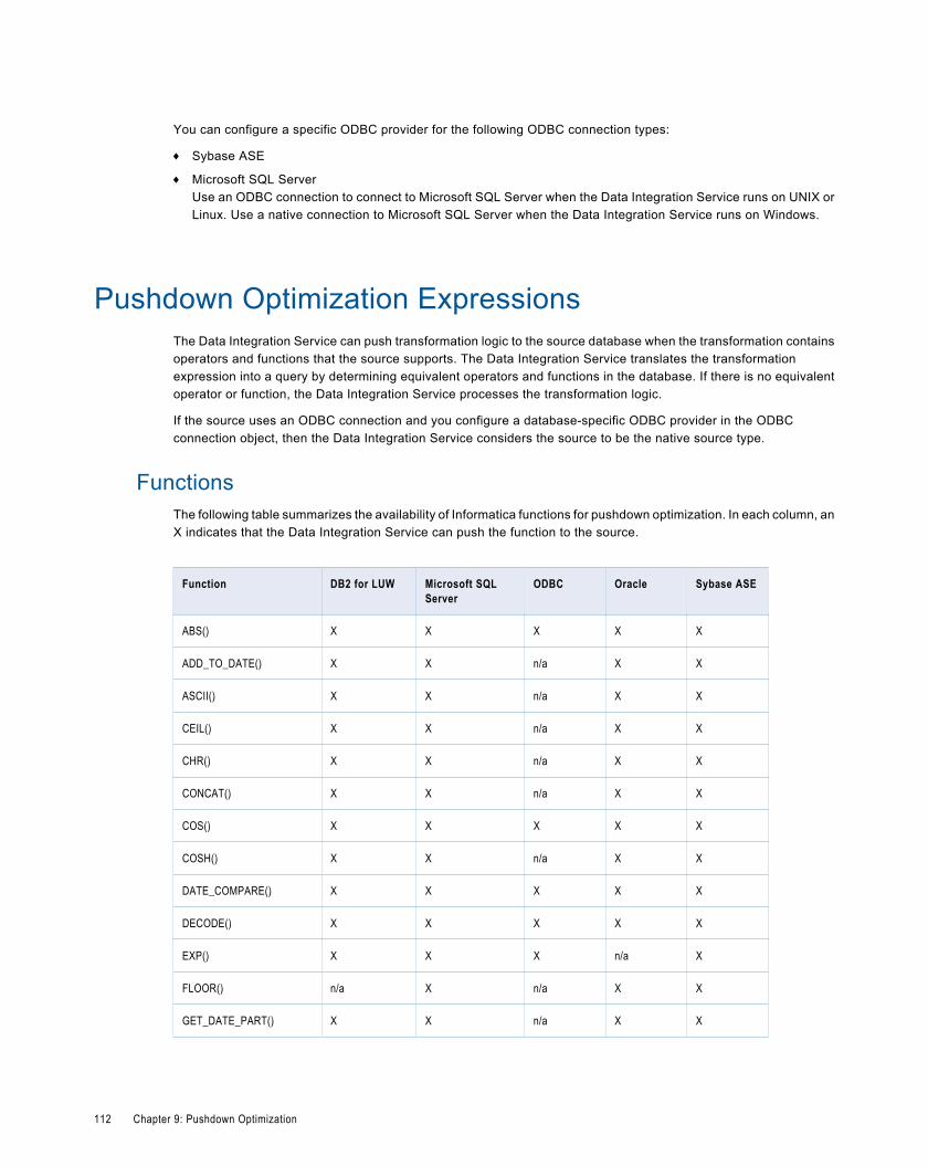
You can configure a specific ODBC provider for the following ODBC connection types:
¨ Sybase ASE
¨ Microsoft SQL ServerUse an ODBC connection to connect to Microsoft SQL Server when the Data Integration Service runs on UNIX orLinux. Use a native connection to Microsoft SQL Server when the Data Integration Service runs on Windows.
Pushdown Optimization ExpressionsThe Data Integration Service can push transformation logic to the source database when the transformation containsoperators and functions that the source supports. The Data Integration Service translates the transformationexpression into a query by determining equivalent operators and functions in the database. If there is no equivalentoperator or function, the Data Integration Service processes the transformation logic.
If the source uses an ODBC connection and you configure a database-specific ODBC provider in the ODBCconnection object, then the Data Integration Service considers the source to be the native source type.
FunctionsThe following table summarizes the availability of Informatica functions for pushdown optimization. In each column, anX indicates that the Data Integration Service can push the function to the source.
Function DB2 for LUW Microsoft SQLServer
ODBC Oracle Sybase ASE
ABS() X X X X X
ADD_TO_DATE() X X n/a X X
ASCII() X X n/a X X
CEIL() X X n/a X X
CHR() X X n/a X X
CONCAT() X X n/a X X
COS() X X X X X
COSH() X X n/a X X
DATE_COMPARE() X X X X X
DECODE() X X X X X
EXP() X X X n/a X
FLOOR() n/a X n/a X X
GET_DATE_PART() X X n/a X X
112 Chapter 9: Pushdown Optimization
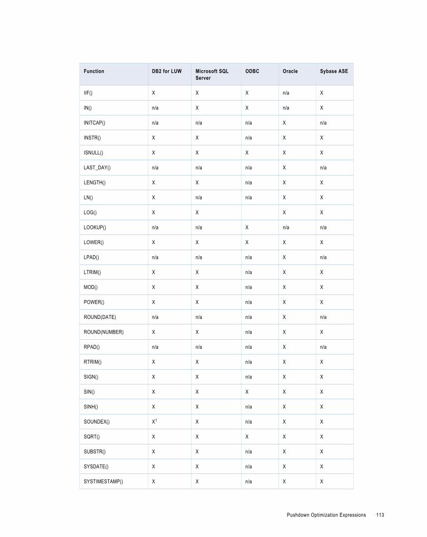
Function DB2 for LUW Microsoft SQLServer
ODBC Oracle Sybase ASE
IIF() X X X n/a X
IN() n/a X X n/a X
INITCAP() n/a n/a n/a X n/a
INSTR() X X n/a X X
ISNULL() X X X X X
LAST_DAY() n/a n/a n/a X n/a
LENGTH() X X n/a X X
LN() X n/a n/a X X
LOG() X X X X
LOOKUP() n/a n/a X n/a n/a
LOWER() X X X X X
LPAD() n/a n/a n/a X n/a
LTRIM() X X n/a X X
MOD() X X n/a X X
POWER() X X n/a X X
ROUND(DATE) n/a n/a n/a X n/a
ROUND(NUMBER) X X n/a X X
RPAD() n/a n/a n/a X n/a
RTRIM() X X n/a X X
SIGN() X X n/a X X
SIN() X X X X X
SINH() X X n/a X X
SOUNDEX() X1 X n/a X X
SQRT() X X X X X
SUBSTR() X X n/a X X
SYSDATE() X X n/a X X
SYSTIMESTAMP() X X n/a X X
Pushdown Optimization Expressions 113
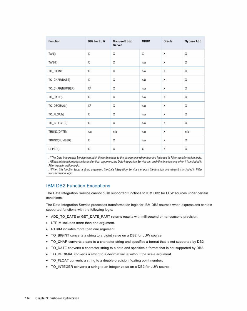
Function DB2 for LUW Microsoft SQLServer
ODBC Oracle Sybase ASE
TAN() X X X X X
TANH() X X n/a X X
TO_BIGINT X X n/a X X
TO_CHAR(DATE) X X n/a X X
TO_CHAR(NUMBER) X2 X n/a X X
TO_DATE() X X n/a X X
TO_DECIMAL() X3 X n/a X X
TO_FLOAT() X X n/a X X
TO_INTEGER() X X n/a X X
TRUNC(DATE) n/a n/a n/a X n/a
TRUNC(NUMBER) X X n/a X X
UPPER() X X X X X
. 1The Data Integration Service can push these functions to the source only when they are included in Filter transformation logic.
. 2When this function takes a decimal or float argument, the Data Integration Service can push the function only when it is included inFilter transformation logic.. 3When this function takes a string argument, the Data Integration Service can push the function only when it is included in Filtertransformation logic.
IBM DB2 Function ExceptionsThe Data Integration Service cannot push supported functions to IBM DB2 for LUW sources under certainconditions.
The Data Integration Service processes transformation logic for IBM DB2 sources when expressions containsupported functions with the following logic:
¨ ADD_TO_DATE or GET_DATE_PART returns results with millisecond or nanosecond precision.
¨ LTRIM includes more than one argument.
¨ RTRIM includes more than one argument.
¨ TO_BIGINT converts a string to a bigint value on a DB2 for LUW source.
¨ TO_CHAR converts a date to a character string and specifies a format that is not supported by DB2.
¨ TO_DATE converts a character string to a date and specifies a format that is not supported by DB2.
¨ TO_DECIMAL converts a string to a decimal value without the scale argument.
¨ TO_FLOAT converts a string to a double-precision floating point number.
¨ TO_INTEGER converts a string to an integer value on a DB2 for LUW source.
114 Chapter 9: Pushdown Optimization
Microsoft SQL Server Function ExceptionsThe Data Integration Service cannot push supported functions to Microsoft SQL Server sources under certainconditions.
The Data Integration Service processes transformation logic for Microsoft SQL Server sources when expressionscontain supported functions with the following logic:
¨ IN includes the CaseFlag argument.
¨ INSTR includes more than three arguments.
¨ LTRIM includes more than one argument.
¨ RTRIM includes more than one argument.
¨ TO_BIGINT includes more than one argument.
¨ TO_INTEGER includes more than one argument.
Oracle Function ExceptionsThe Data Integration Service cannot push supported functions to Oracle sources under certain conditions.
The Data Integration Service processes transformation logic for Oracle sources when expressions contain supportedfunctions with the following logic:
¨ ADD_TO_DATE or GET_DATE_PART returns results with subsecond precision.
¨ ROUND rounds values to seconds or subseconds.
¨ SYSTIMESTAMP returns the date and time with microsecond precision.
¨ TRUNC truncates seconds or subseconds.
ODBC Function ExceptionThe Data Integration Service processes transformation logic for ODBC when the CaseFlag argument for the INfunction is a number other than zero.
Note: When the ODBC connection object properties include a database-specific ODBC provider, the Data IntegrationService considers the source to be the native source type.
Sybase ASE Function ExceptionsThe Data Integration Service cannot push supported functions to Sybase ASE sources under certain conditions.
The Data Integration Service processes transformation logic for Sybase ASE sources when expressions containsupported functions with the following logic:
¨ IN includes the CaseFlag argument.
¨ INSTR includes more than two arguments.
¨ LTRIM includes more than one argument.
¨ RTRIM includes more than one argument.
¨ TO_BIGINT includes more than one argument.
¨ TO_INTEGER includes more than one argument.
¨ TRUNC(Numbers) includes more than one argument.
Pushdown Optimization Expressions 115
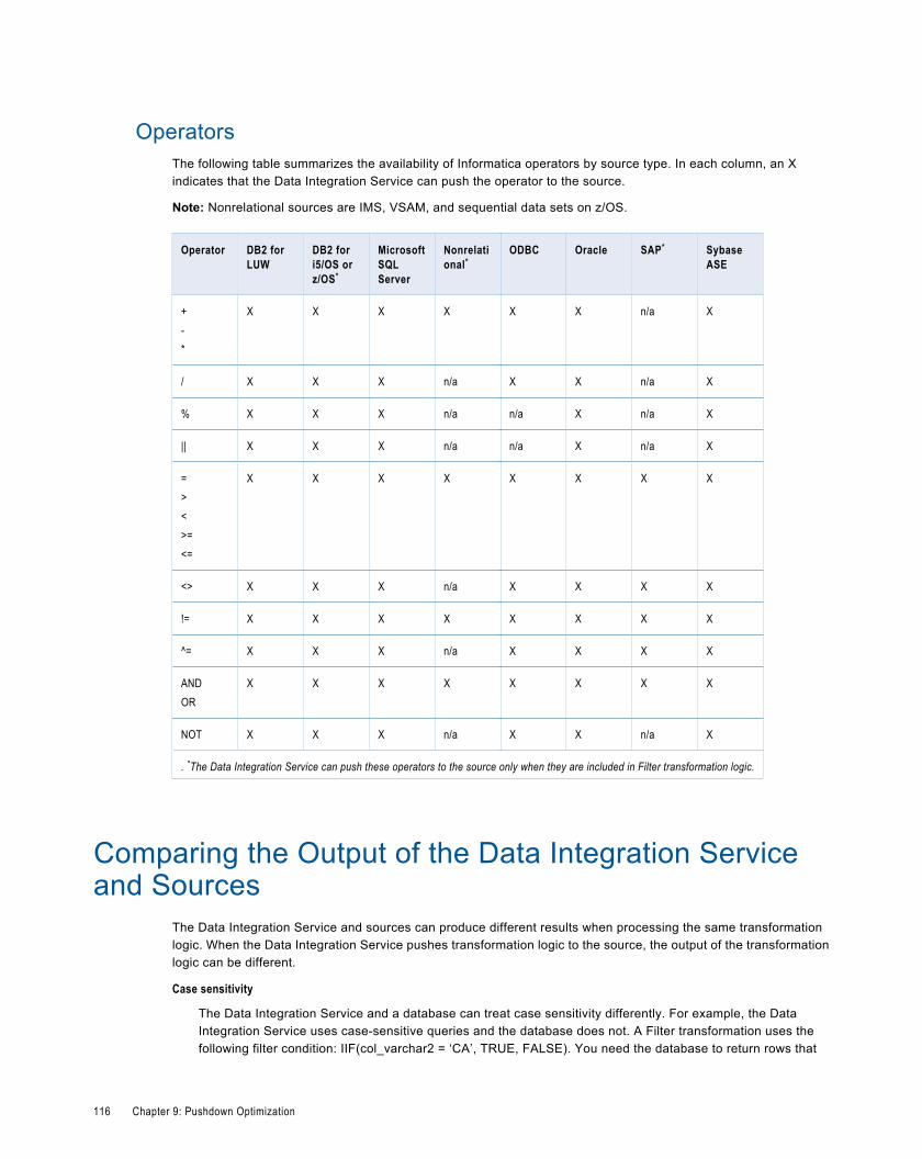
OperatorsThe following table summarizes the availability of Informatica operators by source type. In each column, an Xindicates that the Data Integration Service can push the operator to the source.
Note: Nonrelational sources are IMS, VSAM, and sequential data sets on z/OS.
Operator DB2 forLUW
DB2 fori5/OS orz/OS*
MicrosoftSQLServer
Nonrelational*
ODBC Oracle SAP* SybaseASE
+-*
X X X X X X n/a X
/ X X X n/a X X n/a X
% X X X n/a n/a X n/a X
|| X X X n/a n/a X n/a X
=><>=<=
X X X X X X X X
<> X X X n/a X X X X
!= X X X X X X X X
^= X X X n/a X X X X
ANDOR
X X X X X X X X
NOT X X X n/a X X n/a X
. *The Data Integration Service can push these operators to the source only when they are included in Filter transformation logic.
Comparing the Output of the Data Integration Serviceand Sources
The Data Integration Service and sources can produce different results when processing the same transformationlogic. When the Data Integration Service pushes transformation logic to the source, the output of the transformationlogic can be different.
Case sensitivity
The Data Integration Service and a database can treat case sensitivity differently. For example, the DataIntegration Service uses case-sensitive queries and the database does not. A Filter transformation uses thefollowing filter condition: IIF(col_varchar2 = ‘CA’, TRUE, FALSE). You need the database to return rows that
116 Chapter 9: Pushdown Optimization
match ‘CA.’ However, if you push this transformation logic to a database that is not case sensitive, it returns rowsthat match the values ‘Ca,’ ‘ca,’ ‘cA,’ and ‘CA.’
Numeric values converted to character values
The Data Integration Service and a database can convert the same numeric value to a character value in differentformats. The database might convert numeric values to an unacceptable character format. For example, a tablecontains the number 1234567890. When the Data Integration Service converts the number to a character value,it inserts the characters ‘1234567890.’ However, a database might convert the number to ‘1.2E9.’ The two sets ofcharacters represent the same value.
Date formats for TO_CHAR and TO_DATE functions
The Data Integration Service uses the date format in the TO_CHAR or TO_DATE function when the DataIntegration Service pushes the function to the database. Use the TO_DATE functions to compare date or timevalues. When you use TO_CHAR to compare date or time values, the database can add a space or leading zeroto values such as a single-digit month, single-digit day, or single-digit hour. The database comparison results canbe different from the results of the Data Integration Service when the database adds a space or a leading zero.
Precision
The Data Integration Service and a database can have different precision for particular datatypes.Transformation datatypes use a default numeric precision that can vary from the native datatypes. The resultscan vary if the database uses a different precision than the Data Integration Service.
SYSDATE or SYSTIMESTAMP function
When you use the SYSDATE or SYSTIMESTAMP, the Data Integration Service returns the current date and timefor the node that runs the service process. However, when you push the transformation logic to the database, thedatabase returns the current date and time for the machine that hosts the database. If the time zone of themachine that hosts the database is not the same as the time zone of the machine that runs the Data IntegrationService process, the results can vary.
If you push SYSTIMESTAMP to an IBM DB2 or a Sybase ASE database, and you specify the format forSYSTIMESTAMP, the database ignores the format and returns the complete time stamp.
LTRIM, RTRIM, or SOUNDEX function
When you push LTRIM, RTRIM, or SOUNDEX to a database, the database treats the argument (' ') as NULL, butthe Data Integration Service treats the argument (' ') as spaces.
LAST_DAY function on Oracle source
When you push LAST_DAY to Oracle, Oracle returns the date up to the second. If the input date containssubseconds, Oracle trims the date to the second.
Comparing the Output of the Data Integration Service and Sources 117
C H A P T E R 1 0
MappletsThis chapter includes the following topics:
¨ Mapplets Overview, 118
¨ Mapplet Types, 118
¨ Mapplets and Rules, 119
¨ Mapplet Input and Output, 119
¨ Creating a Mapplet, 120
¨ Validating a Mapplet, 120
Mapplets OverviewA mapplet is a reusable object containing a set of transformations that you can use in multiple mappings. Use amapplet in a mapping. Or, validate the mapplet as a rule.
Transformations in a mapplet can be reusable or non-reusable.
When you use a mapplet in a mapping, you use an instance of the mapplet. Any change made to the mapplet isinherited by all instances of the mapplet.
Mapplets can contain other mapplets. You can also use a mapplet more than once in a mapping or mapplet. Youcannot have circular nesting of mapplets. For example, if mapplet A contains mapplet B, mapplet B cannot containmapplet A.
Mapplet TypesThe mapplet type is determined by the mapplet input and output.
You can create the following types of mapplet:
¨ Source. The mapplet contains a data source as input and an Output transformation as output.
¨ Target. The mapplet contains an Input transformation as input and a data source as output.
¨ Midstream. The mapplet contains an Input transformation and an Output transformation. It does not contain a datasource for input or output.
118
Mapplets and RulesA rule is business logic that defines conditions applied to source data when you run a profile. It is a midstream mappletthat you use in a profile.
A rule must meet the following requirements:
¨ It must contain an Input and Output transformation. You cannot use data sources in a rule.
¨ It can contain Expression transformations and Lookup transformations. It cannot contain any other type oftransformation.
¨ It does not specify cardinality between input groups.
Mapplet Input and OutputTo use a mapplet in a mapping, you must configure it for input and output.
A mapplet has the following input and output components:
¨ Mapplet input. You can pass data into a mapplet from data sources or Input transformations or both. If you validatethe mapplet as a rule, you must pass data into the mapplet through an Input transformation. When you use an Inputtransformation, you connect it to a source or upstream transformation in the mapping.
¨ Mapplet output. You can pass data out of a mapplet from data sources or Output transformations or both. If youvalidate the mapplet as a rule, you must pass data from the mapplet through an Output transformation. When youuse an Output transformation, you connect it to a target or downstream transformation in the mapping.
¨ Mapplet ports. You can see mapplet ports in the mapping editor. Mapplet input ports and output ports originatefrom Input transformations and Output transformations. They do not originate from data sources.
Mapplet InputMapplet input can originate from a data source or from an Input transformation.
You can create multiple pipelines in a mapplet. Use multiple data sources or Input transformations. You can also use acombination of data sources and Input transformations.
Use one or more data sources to provide source data in the mapplet. When you use the mapplet in a mapping, it is thefirst object in the mapping pipeline and contains no input ports.
Use an Input transformation to receive input from the mapping. The Input transformation provides input ports so youcan pass data through the mapplet. Each port in the Input transformation connected to another transformation in themapplet becomes a mapplet input port. Input transformations can receive data from a single active source.Unconnected ports do not appear in the mapping editor.
You can connect an Input transformation to multiple transformations in a mapplet. You can also connect one port in anInput transformation to multiple transformations in the mapplet.
Mapplet OutputUse a data source as output when you want to create a target mapplet. Use an Output transformation in a mapplet topass data through the mapplet into a mapping.
Use one or more data sources to provide target data in the mapplet. When you use the mapplet in a mapping, it is thelast object in the mapping pipeline and contains no output ports.
Mapplets and Rules 119
Use an Output transformation to pass output to a downstream transformation or target in a mapping. Each connectedport in an Output transformation appears as a mapplet output port in a mapping. Each Output transformation in amapplet appears as an output group. An output group can pass data to multiple pipelines in a mapping.
Creating a MappletCreate a mapplet to define a reusable object containing a set of transformations that you can use in multiplemappings.
1. Select a project or folder in the Object Explorer view.
2. Click File > New > Mapplet.
3. Enter a mapplet name.
4. Click Finish.
An empty mapplet appears in the editor.
5. Add mapplet inputs, outputs, and transformations.
Validating a MappletValidate a mapplet before you add it to a mapping. You can also validate a mapplet as a rule to include it in aprofile.
1. Right-click the mapplet editor.
2. Select Validate As > Mapplet or Validate As > Rule.
The Validation Log displays mapplet error messages.
120 Chapter 10: Mapplets
C H A P T E R 1 1
Rule and Mapping ProfilingThis chapter includes the following topics:
¨ Rule and Mapping Profiling Overview, 121
¨ Rule Prerequisites, 121
¨ Mapplet and Mapping Profiling Overview, 122
Rule and Mapping Profiling OverviewYou can add a rule to a profile to cleanse, change, or validate the data. You can create a mapping from a columnprofile. The source of mapping is based on the profile data object. The mapping can contain mapplets andtransformations based on profile rule logic and filters.
Rule PrerequisitesYou can create reusable rules from mapplets in the Developer tool. You can use these rules in profiles to change orvalidate source data.
A rule must meet the following requirements:
¨ It must contain an Input and Output transformation. You cannot use data sources in a rule.
¨ It can contain Expression transformations, Lookup transformations, and passive transformations. It cannot containany other type of transformation. For example, a rule cannot contain a Sorter transformation as it is an activetransformation.
¨ It does not specify cardinality between input groups.
Creating a Rule in Informatica DeveloperYou need to validate a mapplet as a rule to create a rule in the Developer tool.
Create a mapplet in the Developer tool.
1. Right-click the mapplet editor.
2. Select Validate As > Rule.
121
Applying a RuleYou can add a rule to a saved column profile.
1. Browse the Object Explorer view and find the profile you need.
2. Right-click the profile and select Open.
The profile opens in the editor.
3. Click the Definition tab, and select Rules.
4. Click Add.
The Apply Rule dialog box opens.
5. Click Browse to find the rule you want to apply.
Select a rule from a repository project, and click OK.
6. Click the Value column under Input Values to select an input port for the rule.
7. Optionally, click the Value column under Output Values to edit the name of the rule output port.
The rule appears in the Definition tab.
Mapplet and Mapping Profiling OverviewYou can define a column profile for an object in a mapplet or mapping. Run a profile on a mapplet or a mapping objectwhen you want to verify the design of the mapping or mapplet without saving the profile results. You can also generatea mapping from a profile.
Generating a Mapping from a ProfileYou can create a mapping object from a profile. Use the mapping object you create to develop a valid mapping. Themapping you create has a data source based on the profiled object and can contain transformations based on profilerule logic. After you create the mapping, add objects to complete it.
1. In the Object Explorer view, find the profile on which to create the mapping.
2. Right-click the profile name and select Generate Mapping.
The Generate Mapping dialog box displays.
3. Enter a mapping name. Optionally, enter a description for the mapping.
4. Confirm the folder location for the mapping.
By default, the Developer tool creates the mapping in the Mappings folder in the same project as the profile. ClickBrowse to select a different location for the mapping.
5. Confirm the profile definition that the Developer tool uses to create the mapping. To use another profile, clickSelect Profile.
6. Click Finish.
The mapping appears in the Object Explorer.
Add objects to the mapping to complete it.
122 Chapter 11: Rule and Mapping Profiling
Running a Profile on a Mapplet or Mapping ObjectWhen you run a profile on a mapplet or mapping object, the profile runs on all data columns and enables drill-downoperations on the data. You can run a profile on a mapplet or mapping object with multiple output ports.
The profile traces the source data through the mapping to the output ports of the object you selected. The profileanalyzes the data that would appear on those ports if you ran the mapping.
1. Open a mapplet or mapping.
2. Verify that the mapplet or mapping is valid.
3. Right-click a data object or transformation and select Profile Now.
If the transformation has multiple output groups, the Select Output Group dialog box appears. If thetransformation has a single output group, the profile results appear on the Results tab of the profile.
4. If the transformation has multiple output groups, select the output groups as necessary.
5. Click OK.
The profile results appears in the Results tab of the profile.
Comparing Profiles for Mapping or Mapplet ObjectsYou can create a profile that analyzes two objects in a mapplet or mapping and compares the results of the columnprofiles for those objects.
Like profiles of single mapping or mapplet objects, profile comparisons run on all data columns and enable drill-downoperations on the data.
1. Open a mapplet or mapping.
2. Verify that the mapplet or mapping is valid.
3. Press the CTRL key and click two objects in the editor.
4. Right-click one of the objects and select Compare Profiles.
5. Optionally, configure the profile comparison to match columns from one object to the other object.
6. Optionally, match columns by clicking a column in one object and dragging it onto a column in the otherobject.
7. Optionally, choose whether the profile analyzes all columns or matched columns only.
8. Click OK.
Mapplet and Mapping Profiling Overview 123
C H A P T E R 1 2
Object Import and ExportThis chapter includes the following topics:
¨ Object Import and Export Overview, 124
¨ Import and Export Objects, 124
¨ Object Export, 125
¨ Object Import, 126
Object Import and Export OverviewYou can export multiple objects from a project to one XML file. When you import objects, you can choose individualobjects in the XML file or all the objects in the XML file.
You can export objects to an XML file and then import objects from the XML file. When you export objects, theDeveloper tool creates an XML file that contains the metadata of the exported objects. Use the XML file to import theobjects into a project or folder. You can also import and export objects through infacmd command.
Export and import objects to accomplish the following tasks:
¨ Deploy metadata into production. After you test a mapping in a development repository, you can export it to anXML file and then import it from the XML file into a production repository.
¨ Archive metadata. You can export objects to an XML file that you no longer need before you remove them from therepository.
¨ Share metadata. You can share metadata with a third party. For example, you can send a mapping to someoneelse for testing or analysis.
You can use infacmd to generate a readable XML file from an export file. You can also edit the object names in thereadable XML and update the export XML before you import the objects into a repository.
Import and Export ObjectsYou can import and export projects and objects in a project. You can also import and export application archive files ina repository.
When you export an object, the Developer tool also exports the dependent objects. A dependent object is an objectthat is used by another object. For example, a physical data object used as a mapping input is a dependent object ofthat mapping. When you import an object, the Developer tool imports all the dependent objects.
124
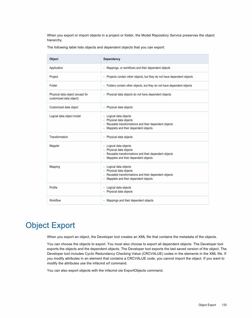
When you export or import objects in a project or folder, the Model Repository Service preserves the objecthierarchy.
The following table lists objects and dependent objects that you can export:
Object Dependency
Application - Mappings, or workflows and their dependent objects
Project - Projects contain other objects, but they do not have dependent objects
Folder - Folders contain other objects, but they do not have dependent objects
Physical data object (except forcustomized data object)
- Physical data objects do not have dependent objects
Customized data object - Physical data objects
Logical data object model - Logical data objects- Physical data objects- Reusable transformations and their dependent objects- Mapplets and their dependent objects
Transformation - Physical data objects
Mapplet - Logical data objects- Physical data objects- Reusable transformations and their dependent objects- Mapplets and their dependent objects
Mapping - Logical data objects- Physical data objects- Reusable transformations and their dependent objects- Mapplets and their dependent objects
Profile - Logical data objects- Physical data objects
Workflow - Mappings and their dependent objects
Object ExportWhen you export an object, the Developer tool creates an XML file that contains the metadata of the objects.
You can choose the objects to export. You must also choose to export all dependent objects. The Developer toolexports the objects and the dependent objects. The Developer tool exports the last saved version of the object. TheDeveloper tool includes Cyclic Redundancy Checking Value (CRCVALUE) codes in the elements in the XML file. Ifyou modify attributes in an element that contains a CRCVALUE code, you cannot import the object. If you want tomodify the attributes use the infacmd xrf command.
You can also export objects with the infacmd oie ExportObjects command.
Object Export 125
Exporting ObjectsYou can export objects to an XML file to use in another project or folder.
1. Click File > Export.
2. Select Informatica > Export Object Metadata File.
3. Click Next.
4. Click Browse to select a project from which to export objects.
5. Click Next.
6. Select the objects to export.
7. Enter the export file name and location.
8. To view the dependent objects that the Export wizard exports with the objects you selected, click Next.
The Export wizard displays the dependent objects.
9. Click Finish.
The Developer tool exports the objects to the XML file.
Object ImportYou can import a project or objects within project from an export file. You can import the objects and any dependentobjects into a project or folder.
When you import objects, you can import a project or individual objects. Import a project when you want to reuse allobjects in the project. Import individual objects when you want to reuse objects across projects. You cannot importobjects from an export file that you created in a previous version.
When you import an object, the Developer Tool lists all the dependent objects. You must add each dependent object tothe target before you can import the object.
When you import objects, an object in the export file might have the same name as an object in the target project orfolder. You can choose how you want to resolve naming conflicts.
You can also import objects with the infacmd oie ImportObjects command.
Importing ProjectsYou can import a project from an XML file into the target repository. You can also import the contents of the project intoa project in the target repository.
1. Click File > Import.
2. Select Informatica > Import Object Metadata File (Basic).
3. Click Next.
4. Click Browse and select the export file that you want to import.
5. Click Next.
6. Select the project or select "<project name> Project Content" in the Source pane.
¨ If you select the project in the Source pane, select the Model Repository Service in the Target pane where youwant to import the project.
126 Chapter 12: Object Import and Export
¨ If you select the project content in the Source pane, select the project to which you want to import the projectcontents in the Target pane.
7. Click Add to Target to add the project to the target.
Tip: You can also drag the project from the Source pane into the repository in the Target pane. Or, you can dragthe project content in the Source pane into a project in the Target pane.
8. Click Resolution to specify how to handle duplicate objects.
You can rename the imported object, replace the existing object with the imported object, or reuse the existingobject. The Developer tool renames all the duplicate objects by default.
9. Click Next.
The Developer tool summarizes the objects to be imported. Click Link Source and Target Objects to link theobjects in the Source and Target display panes when you select one of the objects. For example, if you select thisoption and then select an object in the Source pane, the Developer tool selects the same object in the Targetpane.
10. Map the connections from the import file to the target domain connections in the Additional Import Settings pane.You can also select whether to overwrite existing tags on the objects.
11. Click Finish.
If you chose to rename the duplicate project, the Model Repository Service appends a number to the object name. Youcan rename the project after you import it.
Importing ObjectsYou can import objects from an XML file or application archive file. You import the objects and any dependent objectsinto a project.
1. Click File > Import.
2. Select Informatica > Import Object Metadata File (Advanced).
3. Click Next.
4. Click Browse to select the export file that you want to import.
5. Click Next.
6. Select the object in the Source pane that you want to import.
7. Select the project in the Target pane to which you want to import the object.
8. Click Add to Target to add the object to the target.
If you click Auto Match to Target, the Developer tool tries to match the descendants of the current sourceselection individually by name, type, and parent hierarchy in the target selection and adds the objects thatmatch.
If you want to import all the objects under a folder or a project, select the target folder or project and click AddContent to Target.
Tip: You can also drag the object from the Source pane into the required project in the Target pane. Press thecontrol key while you drag to maintain the object hierarchy in source and target.
9. Click Resolution to specify how to handle duplicate objects.
You can rename the imported object, replace the existing object with the imported object, or reuse the existingobject. The Developer tool renames all the duplicate objects by default.
10. Click Next.
The Developer tool lists any dependent objects in the import file.
11. Add dependent objects to a target folder or project.
Object Import 127
12. Click Next.
The Developer tool summarizes the objects to be imported. Click Link Source and Target Objects to link theobjects in the Source and Target display panes when you select one of the objects. For example, if you select thisoption and then select an object in the Source pane, the Developer tool selects the same object in the Targetpane.
13. Map the connections from the import file to the target domain connections in the Additional Import Settings pane.You can also select whether to overwrite existing tags on the objects.
14. Click Finish.
If you choose to rename the duplicate project, the Import wizard names the imported project as "<OriginalName>_<number of the copy>." You can rename the project after you import it.
128 Chapter 12: Object Import and Export
C H A P T E R 1 3
DeploymentThis chapter includes the following topics:
¨ Deployment Overview, 129
¨ Deployment Methods, 130
¨ Creating an Application, 130
¨ Deploying an Object to a Data Integration Service, 131
¨ Deploying an Object to a File, 131
¨ Updating an Application, 131
¨ Importing Application Archives, 132
¨ Mapping Deployment Properties, 132
¨ Application Redeployment, 133
Deployment OverviewDeploy objects to make them accessible to end users. You can deploy physical data objects, logical data objects,mappings, mapplets, workflows, and applications.
Deploy objects to allow users to query the objects through a third-party client tool or to run mappings or workflows atthe command line. When you deploy an object, you isolate the object from changes in data structures. If you makechanges to an object in the Developer tool after you deploy it, you must redeploy the application that contains theobject for the changes to take effect.
You can deploy objects to a Data Integration Service or a network file system. When you deploy an application to aData Integration Service, end users can connect to the application. Depending on the types of objects in theapplication, end users can then run queries against the objects, or run mappings or workflows. The end users musthave the appropriate permissions in the Administrator tool to perform these tasks.
When you deploy an object to a network file system, the Developer tool creates an application archive file. Deploy anobject to a network file system if you want to check the application into a version control system. You can also deployan object to a file if your organization requires that administrators deploy objects to Data Integration Services. Anadministrator can deploy application archive files to Data Integration Services through the Administrator tool. You canalso import objects from an application archive into projects or folders in the Model repository.
129
Deployment MethodsDeploy objects or deploy an application that contains one or more objects. The object deployment method differsbased on the type of object that you deploy.
Deploy an objectDeploy an object to make the object available to end users. If you redeploy an object to a Data Integration Service, youcannot update the application. The Developer tool creates an application with a different name.
When you deploy the following objects, the Developer tool prompts you to create an application and the Developer tooladds the object to the application:
¨ Mappings
¨ Workflows
Deploy an application that contains objectsCreate an application to deploy multiple objects at the same time. When you create an application, you select theobjects to include in the application. If you redeploy an application to a Data Integration Service you can update orreplace the application.
Creating an ApplicationCreate an application when you want to deploy multiple objects at the same time or if you want to be able to update orreplace the application when it resides on the Data Integration Service. When you create an application, you select theobjects to include in the application.
1. Select a project or folder in the Object Explorer view.
2. Click File > New > Application.
The New Application dialog box appears.
3. Enter a name for the application.
4. Click Browse to select the application location.
You must create the application in a project or a folder.
5. Click Next.
The Developer tool prompts you for the objects to include in the application.
6. Click Add.
The Add Objects dialog box appears.
7. Select one or more objects and click OK.
The Developer tool lists the objects you select in the New Application dialog box.
8. If the application contains mappings, choose whether to override the default mapping configuration when youdeploy the application. If you select this option, choose a mapping configuration.
The Developer tool sets the mapping deployment properties for the application to the same values as the settingsin the mapping configuration.
9. Click Finish.
The Developer tool adds the application to the project or folder.
After you create an application, you must deploy the application so end users can run mappings or workflows.
130 Chapter 13: Deployment
Deploying an Object to a Data Integration ServiceDeploy an object to a Data Integration Service so end users can run mappings or workflows from the commandline.
1. Right-click an object in the Object Explorer view and select Deploy.
The Deploy dialog box appears.
2. Select Deploy to Service.
3. Click Browse to select the domain.
The Choose Domain dialog box appears.
4. Select a domain and click OK.
The Developer tool lists the Data Integration Services associated with the domain in the Available Servicessection of the Deploy Application dialog box.
5. Select the Data Integration Services to which you want to deploy the application. Click Next.
6. Enter an application name.
7. Click Finish.
The Developer tool deploys the application to the Data Integration Service.
Deploying an Object to a FileDeploy an object to an application archive file if you want to check the application into version control or if yourorganization requires that administrators deploy objects to Data Integration Services.
1. Right-click an object in the Object Explorer view and select Deploy.
The Deploy dialog box appears.
2. Select Deploy to File System.
3. Click Browse to select the directory.
The Choose a Directory dialog box appears.
4. Select the directory and click OK. Then, click Next.
5. Enter an application name.
6. Click Finish.
The Developer tool deploys the application to an application archive file.
Before end users can access the application, you must deploy the application to a Data Integration Service. Or, anadministrator must deploy the application to a Data Integration Service through the Administrator tool.
Updating an ApplicationUpdate an application when you want to add objects to an application, remove objects from an application, or updatemapping deployment properties.
Deploying an Object to a Data Integration Service 131
1. Open the application you want to update.
2. To add or remove objects, click the Overview view.
3. To add objects to the application, click Add.
The Developer tool prompts you to choose the objects to add to the application.
4. To remove an object from the application, select the object, and click Remove.
5. To update mapping deployment properties, click the Advanced view and change the properties.
6. Save the application.
Redeploy the application if you want end users to be able to access the updated application.
Importing Application ArchivesYou can import objects from an application archive file. You import the application and dependent objects into therepository.
1. Click File > Import.
The Import wizard appears.
2. Select Informatica > Application Archive.
3. Click Next.
4. Click Browse to select the application archive file.
The Developer tool lists the application archive file contents.
5. Select the repository into which you want to import the application.
6. Click Finish.
The Developer tool imports the application into the repository. If the Developer tool finds duplicate objects, itrenames the imported objects.
Mapping Deployment PropertiesWhen you update an application that contains a mapping, you can set the deployment properties the Data IntegrationServices uses when end users run the mapping.
Set mapping deployment properties on the Advanced view of the application.
You can set the following properties:
Property Description
Default date time format Date/time format the Data Integration Services uses when the mapping converts strings todates.Default is MM/DD/YYYY HH24:MI:SS.
Override tracing level Overrides the tracing level for each transformation in the mapping. The tracing level determinesthe amount of information the Data Integration Service sends to the mapping log files.
132 Chapter 13: Deployment
Property Description
Choose one of the following tracing levels:- None. The Data Integration Service does not override the tracing level that you set for each
transformation.- Terse. The Data Integration Service logs initialization information, error messages, and
notification of rejected data.- Normal. The Data Integration Service logs initialization and status information, errors
encountered, and skipped rows due to transformation row errors. It summarizes mappingresults, but not at the level of individual rows.
- Verbose Initialization. In addition to normal tracing, the Data Integration Service logs additionalinitialization details, names of index and data files used, and detailed transformationstatistics.
- Verbose Data. In addition to verbose initialization tracing, the Data Integration Service logseach row that passes into the mapping. The Data Integration Service also notes where ittruncates string data to fit the precision of a column and provides detailed transformationstatistics. The Data Integration Service writes row data for all rows in a block when it processesa transformation.
Default is None.
Sort order Order in which the Data Integration Service sorts character data in the mapping.Default is Binary.
Optimizer level Controls the optimization methods that the Data Integration Service applies to a mapping asfollows:- None. The Data Integration Service does not optimize the mapping.- Minimal. The Data Integration Service applies the early projection optimization method to the
mapping.- Normal. The Data Integration Service applies the early projection, early selection, pushdown,
and predicate optimization methods to the mapping.- Full. The Data Integration Service applies the early projection, early selection, pushdown,
predicate, cost-based, and semi-join optimization methods to the mapping.Default is Normal.
High precision Runs the mapping with high precision.High precision data values have greater accuracy. Enable high precision if the mapping produceslarge numeric values, for example, values with precision of more than 15 digits, and you requireaccurate values. Enabling high precision prevents precision loss in large numeric values.Default is enabled.
Application RedeploymentWhen you change an application or change an object in the application and you want end users to access the latestversion of the application, you must deploy the application again.
When you change an application or its contents and you deploy the application to the same Data Integration Service,the Developer tool gives you the following choices:
¨ Update. The Data Integration Service replaces the objects and preserves the object properties in the Administratortool.
¨ Replace. The Data Integration Service replaces the objects and resets the object properties in the Administratortool to the default values.
Application Redeployment 133
To update or replace an application that is running, you must first stop the application. When you stop an application,the Data Integration Service aborts all running objects in the application. If you do not want to abort running objects,you can rename the application or deploy the application to a different service.
When you change an application and deploy it to a network file system, the Developer tool allows you to replace theapplication archive file or cancel the deployment. If you replace the application archive file, the Developer toolreplaces the objects in the application and resets the object properties.
Redeploying an ApplicationRedeploy an application to a Data Integration Service when you want to update or replace the application.
1. Right-click an application in the Object Explorer view and click Deploy.
The Deploy dialog box appears.
2. Select Deploy to Service.
3. Click Browse to select the domain.
The Choose Domain dialog box appears.
4. Select a domain and click OK.
The Developer tool lists the Data Integration Services associated with the domain in the Available Servicessection of the Deploy Application dialog box.
5. Select the Data Integration Services to which you want to deploy the application.
6. If the Data Integration Service already contains the deployed application, select to update or replace theapplication in the Action column.
7. If the deployed application is running, select Force the Existing Application to Stop.
8. Click Finish.
134 Chapter 13: Deployment
C H A P T E R 1 4
Mapping Parameters andParameter Files
This chapter includes the following topics:
¨ Mapping Parameters and Parameter Files Overview, 135
¨ System Parameters, 135
¨ User-Defined Parameters, 136
¨ Where to Assign Parameters, 138
¨ Parameter Files, 139
Mapping Parameters and Parameter Files OverviewA mapping parameter represents a constant value that can change between mapping runs, such as connections,source file directories, or cache file directories.
You can use system or user-defined parameters when you run a mapping. System parameters define the directorieswhere the Data Integration Service stores cache files, reject files, source files, target files, and temporary files. Youdefine the values of the system parameters on a Data Integration Service process in the Administrator tool.
User-defined parameters allow you to define mapping values in a parameter file and update those values each timeyou run a mapping. Create user-defined parameters so that you can rerun a mapping with different connection, flatfile, cache file, or temporary file values. You define the parameter values in a parameter file. When you run themapping from the command line and specify a parameter file, the Data Integration Service uses the parameter valuesdefined in the parameter file.
Note: You can create user-defined workflow parameters when you develop a workflow. A workflow parameter is aconstant value that can change between workflow runs.
System ParametersSystem parameters are constant values that define the directories where the Data Integration Service stores cachefiles, reject files, source files, target files, and temporary files.
You define the values of the system parameters on a Data Integration Service process in the Administrator tool. Youcannot define or override system parameter values in a parameter file.
135
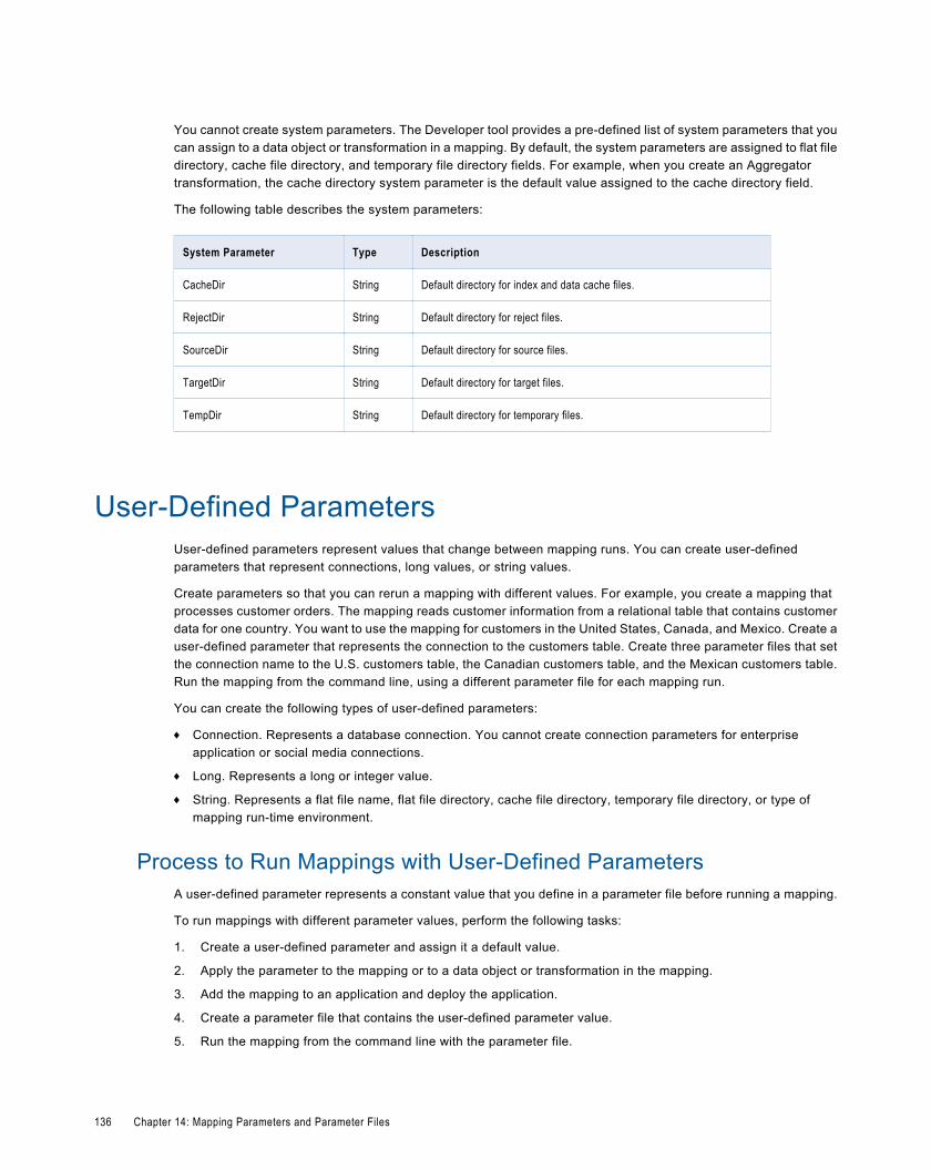
You cannot create system parameters. The Developer tool provides a pre-defined list of system parameters that youcan assign to a data object or transformation in a mapping. By default, the system parameters are assigned to flat filedirectory, cache file directory, and temporary file directory fields. For example, when you create an Aggregatortransformation, the cache directory system parameter is the default value assigned to the cache directory field.
The following table describes the system parameters:
System Parameter Type Description
CacheDir String Default directory for index and data cache files.
RejectDir String Default directory for reject files.
SourceDir String Default directory for source files.
TargetDir String Default directory for target files.
TempDir String Default directory for temporary files.
User-Defined ParametersUser-defined parameters represent values that change between mapping runs. You can create user-definedparameters that represent connections, long values, or string values.
Create parameters so that you can rerun a mapping with different values. For example, you create a mapping thatprocesses customer orders. The mapping reads customer information from a relational table that contains customerdata for one country. You want to use the mapping for customers in the United States, Canada, and Mexico. Create auser-defined parameter that represents the connection to the customers table. Create three parameter files that setthe connection name to the U.S. customers table, the Canadian customers table, and the Mexican customers table.Run the mapping from the command line, using a different parameter file for each mapping run.
You can create the following types of user-defined parameters:
¨ Connection. Represents a database connection. You cannot create connection parameters for enterpriseapplication or social media connections.
¨ Long. Represents a long or integer value.
¨ String. Represents a flat file name, flat file directory, cache file directory, temporary file directory, or type ofmapping run-time environment.
Process to Run Mappings with User-Defined ParametersA user-defined parameter represents a constant value that you define in a parameter file before running a mapping.
To run mappings with different parameter values, perform the following tasks:
1. Create a user-defined parameter and assign it a default value.
2. Apply the parameter to the mapping or to a data object or transformation in the mapping.
3. Add the mapping to an application and deploy the application.
4. Create a parameter file that contains the user-defined parameter value.
5. Run the mapping from the command line with the parameter file.
136 Chapter 14: Mapping Parameters and Parameter Files
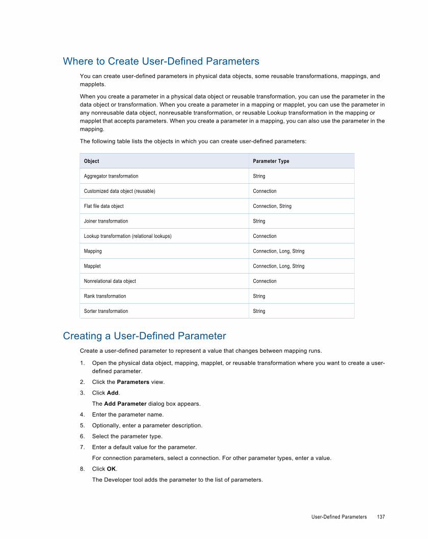
Where to Create User-Defined ParametersYou can create user-defined parameters in physical data objects, some reusable transformations, mappings, andmapplets.
When you create a parameter in a physical data object or reusable transformation, you can use the parameter in thedata object or transformation. When you create a parameter in a mapping or mapplet, you can use the parameter inany nonreusable data object, nonreusable transformation, or reusable Lookup transformation in the mapping ormapplet that accepts parameters. When you create a parameter in a mapping, you can also use the parameter in themapping.
The following table lists the objects in which you can create user-defined parameters:
Object Parameter Type
Aggregator transformation String
Customized data object (reusable) Connection
Flat file data object Connection, String
Joiner transformation String
Lookup transformation (relational lookups) Connection
Mapping Connection, Long, String
Mapplet Connection, Long, String
Nonrelational data object Connection
Rank transformation String
Sorter transformation String
Creating a User-Defined ParameterCreate a user-defined parameter to represent a value that changes between mapping runs.
1. Open the physical data object, mapping, mapplet, or reusable transformation where you want to create a user-defined parameter.
2. Click the Parameters view.
3. Click Add.
The Add Parameter dialog box appears.
4. Enter the parameter name.
5. Optionally, enter a parameter description.
6. Select the parameter type.
7. Enter a default value for the parameter.
For connection parameters, select a connection. For other parameter types, enter a value.
8. Click OK.
The Developer tool adds the parameter to the list of parameters.
User-Defined Parameters 137
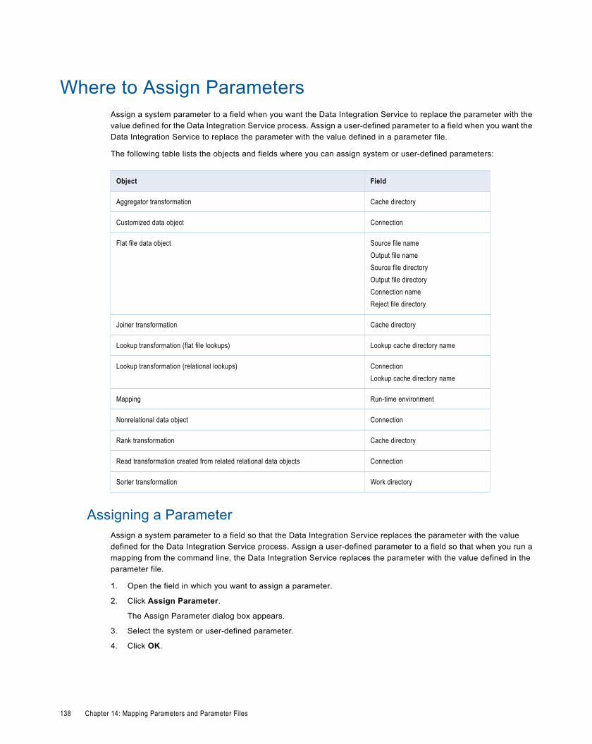
Where to Assign ParametersAssign a system parameter to a field when you want the Data Integration Service to replace the parameter with thevalue defined for the Data Integration Service process. Assign a user-defined parameter to a field when you want theData Integration Service to replace the parameter with the value defined in a parameter file.
The following table lists the objects and fields where you can assign system or user-defined parameters:
Object Field
Aggregator transformation Cache directory
Customized data object Connection
Flat file data object Source file nameOutput file nameSource file directoryOutput file directoryConnection nameReject file directory
Joiner transformation Cache directory
Lookup transformation (flat file lookups) Lookup cache directory name
Lookup transformation (relational lookups) ConnectionLookup cache directory name
Mapping Run-time environment
Nonrelational data object Connection
Rank transformation Cache directory
Read transformation created from related relational data objects Connection
Sorter transformation Work directory
Assigning a ParameterAssign a system parameter to a field so that the Data Integration Service replaces the parameter with the valuedefined for the Data Integration Service process. Assign a user-defined parameter to a field so that when you run amapping from the command line, the Data Integration Service replaces the parameter with the value defined in theparameter file.
1. Open the field in which you want to assign a parameter.
2. Click Assign Parameter.
The Assign Parameter dialog box appears.
3. Select the system or user-defined parameter.
4. Click OK.
138 Chapter 14: Mapping Parameters and Parameter Files
Parameter FilesA parameter file is an XML file that lists user-defined parameters and their assigned values. Parameter files providethe flexibility to change parameter values each time you run a mapping.
The parameter values define properties for a mapping, mapplet, physical data object, or transformation. The DataIntegration Service applies these values when you run a mapping from the command line and specify a parameterfile.
You cannot define system parameter values in a parameter file.
You can define parameters for multiple mappings in a single parameter file. You can also create multiple parameterfiles and use a different file each time you run a mapping. The Data Integration Service reads the parameter file at thestart of the mapping run to resolve the parameters.
Use the infacmd ms ListMappingParams command to list the parameters used in a mapping with the default values.You can use the output of this command as a parameter file template.
Use the infacmd ms RunMapping command to run a mapping with a parameter file.
Note: Parameter files for mappings and workflows use the same structure. You can define parameters for deployedmappings and for deployed workflows in a single parameter file.
Parameter File StructureA parameter file is an XML file that contains at least one parameter and its assigned value.
The Data Integration Service uses the hierarchy defined in the parameter file to identify parameters and their definedvalues. The hierarchy identifies the mapping, mapplet, physical data object, or transformation that uses theparameter.
You define parameter values within a project or application top-level element. A project element defines parametervalues to use when you run a specific mapping in the project in any deployed application. A project element alsodefines the parameter values to use when you run any mapping that uses the objects in the project. An applicationelement defines parameter values to use when you run a specific mapping in a specific deployed application. If youdefine the same parameter in a project top-level element and an application top-level element in the same parameterfile, the parameter value defined in the application element takes precedence.
The Data Integration Service searches for parameter values in the following order:
1. The value specified within an application element.
2. The value specified within a project element.
3. The parameter default value.
A parameter file must conform to the structure of the parameter file XML schema definition (XSD). If the parameter filedoes not conform to the schema definition, the Data Integration Service fails the mapping run.
On the machine that hosts the Developer tool, the parameter file XML schema definition appears in the followingdirectory:
<Informatica Installation Directory>\clients\DeveloperClient\infacmd\plugins\ms\parameter_file_schema_1_0.xsd
On the machine that hosts Informatica Services, the parameter file XML schema definition appears in the followingdirectory:
<Informatica Installation Directory>\isp\bin\plugins\ms\parameter_file_schema_1_0.xsd
Parameter Files 139
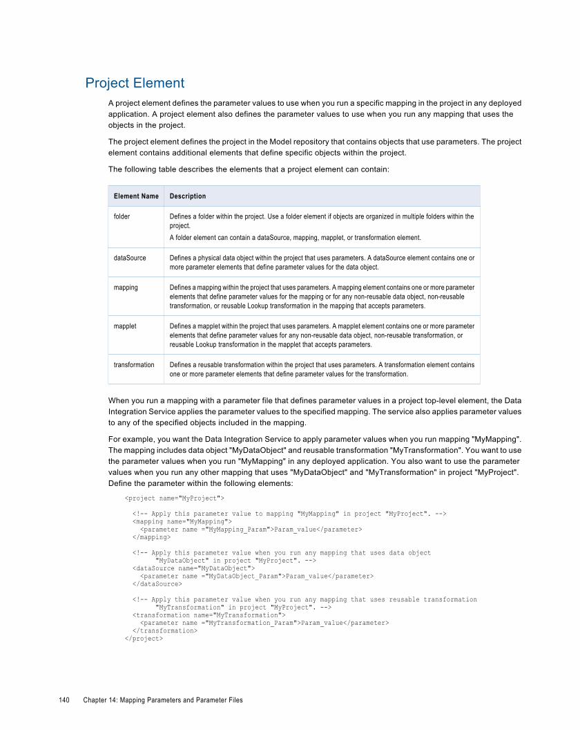
Project ElementA project element defines the parameter values to use when you run a specific mapping in the project in any deployedapplication. A project element also defines the parameter values to use when you run any mapping that uses theobjects in the project.
The project element defines the project in the Model repository that contains objects that use parameters. The projectelement contains additional elements that define specific objects within the project.
The following table describes the elements that a project element can contain:
Element Name Description
folder Defines a folder within the project. Use a folder element if objects are organized in multiple folders within theproject.A folder element can contain a dataSource, mapping, mapplet, or transformation element.
dataSource Defines a physical data object within the project that uses parameters. A dataSource element contains one ormore parameter elements that define parameter values for the data object.
mapping Defines a mapping within the project that uses parameters. A mapping element contains one or more parameterelements that define parameter values for the mapping or for any non-reusable data object, non-reusabletransformation, or reusable Lookup transformation in the mapping that accepts parameters.
mapplet Defines a mapplet within the project that uses parameters. A mapplet element contains one or more parameterelements that define parameter values for any non-reusable data object, non-reusable transformation, orreusable Lookup transformation in the mapplet that accepts parameters.
transformation Defines a reusable transformation within the project that uses parameters. A transformation element containsone or more parameter elements that define parameter values for the transformation.
When you run a mapping with a parameter file that defines parameter values in a project top-level element, the DataIntegration Service applies the parameter values to the specified mapping. The service also applies parameter valuesto any of the specified objects included in the mapping.
For example, you want the Data Integration Service to apply parameter values when you run mapping "MyMapping".The mapping includes data object "MyDataObject" and reusable transformation "MyTransformation". You want to usethe parameter values when you run "MyMapping" in any deployed application. You also want to use the parametervalues when you run any other mapping that uses "MyDataObject" and "MyTransformation" in project "MyProject".Define the parameter within the following elements:
<project name="MyProject">
<!-- Apply this parameter value to mapping "MyMapping" in project "MyProject". --> <mapping name="MyMapping"> <parameter name ="MyMapping_Param">Param_value</parameter> </mapping>
<!-- Apply this parameter value when you run any mapping that uses data object "MyDataObject" in project "MyProject". --> <dataSource name="MyDataObject"> <parameter name ="MyDataObject_Param">Param_value</parameter> </dataSource>
<!-- Apply this parameter value when you run any mapping that uses reusable transformation "MyTransformation" in project "MyProject". --> <transformation name="MyTransformation"> <parameter name ="MyTransformation_Param">Param_value</parameter> </transformation></project>
140 Chapter 14: Mapping Parameters and Parameter Files
Application ElementAn application element provides a run-time scope for a project element. An application element defines the parametervalues to use when you run a specific mapping in a specific deployed application.
An application element defines the deployed application that contains objects that use parameters. An applicationelement can contain a mapping element that defines a mapping in the deployed application that uses parameters. Amapping element contains a project element.
For example, you want the Data Integration Service to apply parameter values when you run mapping "MyMapping" indeployed application "MyApp." You do not want to use the parameter values when you run the mapping in any otherapplication or when you run another mapping in project "MyProject." Define the parameters within the followingelements:
<application name="MyApp"> <mapping name="MyMapping"> <project name="MyProject"> <mapping name="MyMapping"> <parameter name ="MyMapping_Param">Param_value</parameter> </mapping>
<dataSource name="MyDataObject"> <parameter name ="MyDataObject_Param">Param_value</parameter> </dataSource>
<transformation name="MyTransformation"> <parameter name ="MyTransformation_Param">Param_value</parameter> </transformation> </project> </mapping></application>
Rules and Guidelines for Parameter FilesCertain rules and guidelines apply when you create parameter files.
Use the following rules when you create a parameter file:
¨ Parameter values cannot be empty. For example, the Data Integration Service fails the mapping run if theparameter file contains the following entry:
<parameter name="Param1"> </parameter>¨ Within an element, artifact names are not case-sensitive. Therefore, the Data Integration Service interprets
<application name="App1"> and <application name="APP1"> as the same application.
Sample Parameter FileThe following example shows a sample parameter file used to run mappings.
<?xml version="1.0"?><root description="Sample Parameter File" xmlns="http://www.informatica.com/Parameterization/1.0" xmlns:xsi="http://www.w3.org/2001/XMLSchema-instance"> <!-- The Data Integration Service uses this section only when you run mapping "Map1" or "Map2" in project "Project1" in deployed application "App1." This section assigns values to parameters created in mappings "Map1" and "Map2." --> <application name="App1"> <mapping name="Map1"> <project name="Project1"> <mapping name="Map1"> <parameter name="MAP1_PARAM1">MAP1_PARAM1_VAL</parameter> <parameter name="MAP1_PARAM2">MAP1_PARAM2_VAL</parameter>
Parameter Files 141
</mapping> </project> </mapping> <mapping name="Map2"> <project name="Project1"> <mapping name="Map2"> <parameter name="MAP2_PARAM1">MAP2_PARAM1_VAL</parameter> <parameter name="MAP2_PARAM2">MAP2_PARAM2_VAL</parameter> </mapping> </project> </mapping> </application> <!-- The Data Integration Service uses this section only when you run mapping "Map1" in project "Project1" in deployed application "App2." This section assigns values to parameters created in the following objects: * Reusable data source "DS1" in mapping "Map1" * Mapping "Map1" --> <application name="App2"> <mapping name="Map1"> <project name="Project1"> <dataSource name="DS1"> <parameter name="PROJ1_DS1">PROJ1_DS1_APP2_MAP1_VAL</parameter> <parameter name="PROJ1_DS1">PROJ1_DS1_APP2_MAP1_VAL</parameter> </dataSource> <mapping name="Map1"> <parameter name="MAP1_PARAM2">MAP1_PARAM2_VAL</parameter> </mapping> </project> </mapping> </application> <!-- The Data Integration Service uses this section when you run any mapping that includes data source "DS1" or mapplet "DS1" in project "Project1." This section assigns values to parameters created in the following objects: * Data source "DS1" * Mapplet "DS1" --> <project name="Project1"> <dataSource name="DS1"> <parameter name="PROJ1_DS1">PROJ1_DS1_VAL</parameter> <parameter name="PROJ1_DS1_PARAM1">PROJ1_DS1_PARAM1_VAL</parameter> </dataSource> <mapplet name="DS1"> <parameter name="PROJ1_DS1">PROJ1_DS1_VAL</parameter> <parameter name="PROJ1_DS1_PARAM1">PROJ1_DS1_PARAM1_VAL</parameter> </mapplet> </project> <!-- The Data Integration Service uses this section when you run any mapping that includes reusable transformation "TX2", mapplet "MPLT1" in folder "Folder2", or Mapplet "RULE1" in nested folder "Folder2_1_1" in project "Project2". This section assigns values to parameters created in the following objects: * Reusable transformation "TX2" * Mapplet "MPLT1" in folder "Folder2" * Mapplet "RULE1" in nested folder "Folder2_1_1" --> <project name="Project2"> <transformation name="TX2"> <parameter name="RTM_PATH">Project1\Folder1\RTM1</parameter> </transformation> <folder name="Folder2"> <mapplet name="MPLT1"> <parameter name="PROJ2_FOLD2_MPLT1">PROJ2_FOLD2_MPLT1_VAL</parameter> </mapplet> <folder name="Folder2_1"> <folder name="Folder2_1_1"> <mapplet name="RULE1"> <parameter name="PROJ2_RULE1">PROJ2_RULE1_VAL</parameter>
142 Chapter 14: Mapping Parameters and Parameter Files
</mapplet> </folder> </folder> </folder> </project></root>
Creating a Parameter FileThe infacmd ms ListMappingParams command lists the parameters used in a mapping in a deployed application andthe default value for each parameter. Use the output of this command to create a parameter file.
The command lists all parameters in a project top-level element. You can edit the parameter default values in theproject element to define the values for a mapping in the project that is deployed to any application. Or, you can copythe project element into an application element to define the values for a specific mapping in a specific deployedapplication.
If the mapping uses objects of the same type that exist in the same project or folder, have the same name, and useparameters, the ms ListMappingParams command fails. If the objects are in different folders, or if one object does notuse parameters, the ms ListMappingParams command successfully lists the parameters used in the mapping.
1. Run the infacmd ms ListMappingParams command to list all parameters used in a mapping and the default valuefor each parameter.
The -o argument sends command output to an XML file.
For example, the following command lists the parameters in mapping MyMapping in file "MyOutputFile.xml":infacmd ms ListMappingParams -dn MyDomain -sn MyDataIntSvs -un MyUser -pd MyPassword -a MyApplication -m MyMapping -o MyOutputFile.xml
The Data Integration Service lists all parameters in the mapping with their default values in a project top-levelelement.
2. If you did not specify the -o argument, copy the command output to an XML file and save the file.
3. Edit the XML file and replace the parameter default values with the values you want to use when you run themapping.
If you want to define the values for the mapping in a specific application, copy the project top-level element into anapplication top-level element.
4. Save the XML file.
Running a Mapping with a Parameter FileUse the infacmd ms RunMapping command to run a mapping with a parameter file. The -pf argument specifies theparameter file name.
For example, the following command runs the mapping MyMapping using the parameter file "MyParamFile.xml":
infacmd ms RunMapping -dn MyDomain -sn MyDataIntSvs -un MyUser -pd MyPassword -a MyApplication -m MyMapping -pf MyParamFile.xml
The Data Integration Service fails the mapping if you run it with a parameter file and any of the following conditions aretrue:
¨ The machine from which you run the infacmd ms RunMapping command cannot access the parameter file.
¨ The parameter file is not valid or does not exist.
¨ Objects of the same type exist in the same project or folder, have the same name, and use parameters.
Parameter Files 143
C H A P T E R 1 5
TagsThis chapter includes the following topics:
¨ Tags Overview, 144
¨ Creating a Tag, 144
¨ Assigning a Tag, 145
¨ Viewing Tags, 145
Tags OverviewA tag is metadata that defines an object in the Model repository based on business usage. Create tags to groupobjects according to their business usage.
After you create a tag, you can associate the tag with one or more objects. You can remove the association between atag and an object. You can use a tag to search for objects associated with the tag in the Model repository. TheDeveloper tool displays a glossary of all tags.
For example, you create a tag named XYZCorp_CustomerOrders and assign it to tables that contain information forthe customer orders from the XYZ Corporation. Users can search by the XYZCorp_CustomerOrders tag to identify thetables associated with the tag.
Creating a TagCreate a tag to add metadata that defines an object based on business usage.
1. To create a tag, use one of the following methods:
Option Description
Preferences dialog box Click Window > Preferences. In the Preferences dialog box, select Informatica > Tags. Select aModel Repository Service and click Add.
Tags view for an object Open an object in the editor. In the Tags view, click Edit. In the Assign Tags for Object dialog box,click New.
2. Enter a name for the tag.
3. Optionally, enter a description.
144
4. Click OK.
Assigning a TagAssign a tag to an object to associate the object with the metadata definition.
1. Open an object in the editor.
2. In the Tags view, click Edit.
The Assign Tags for Object dialog box appears. The Available Tags area displays all tags defined in therepository. You can search for a tag by name or description. The Assign Tags area displays the opened objectand any tags assigned to the object.
3. In the Available Tags area, select a tag.
4. In the Assign Tags area, select the object.
5. Click Assign.
6. To remove a tag from an object, select the tag in the Available Tags area and the object in the Assign Tags area,and then click Remove.
Viewing TagsYou can view all tags assigned to an object, or you can view all tags defined in the Model repository.
1. To view tags assigned to an object, open the object in the editor.
2. Select the Tags view.
The Tags view displays all tags assigned to the object.
3. To view all the tags defined in the Model repository, click Window > Preferences.
The Preferences dialog box appears.
4. Select Informatica > Tags.
The Tags area displays all tags defined in the Model repository. You can search for a tag by name ordescription.
Assigning a Tag 145
C H A P T E R 1 6
Viewing DataThis chapter includes the following topics:
¨ Viewing Data Overview, 146
¨ Configurations, 146
¨ Exporting Data, 151
¨ Logs, 151
¨ Monitoring Jobs from the Developer Tool, 152
Viewing Data OverviewYou can run a mapping, view profile results, or preview data.
You can run mappings from the command line or from the Run dialog box. You can view profile results and previewdata from the Data Viewer view.
Before you can view data, you need to select a default Data Integration Service. You can also add other DataIntegration Services to use when you view data.
Create configurations to control settings that the Developer tool applies when you run a mapping or preview data.
When you view data in the Data Viewer view, you can export the data to a file. You can also access logs that show logevents.
You can monitor applications and jobs from the Progress view.
ConfigurationsA configuration is a group of settings that the Developer tool applies when you run a mapping or preview data.
A configuration controls settings such as the default Data Integration Service, number of rows to read from a source,default date/time format, and optimizer level. The configurations that you create apply to your installation of theDeveloper tool.
You can create the following configurations:
¨ Data viewer configurations. Control the settings the Developer tool applies when you preview output in the DataViewer view.
146
¨ Mapping configurations. Control the settings the Developer tool applies when you run mappings through the RunConfigurations dialog box or from the command line.
Data Viewer ConfigurationsData viewer configurations control the settings that the Developer tool applies when you preview output in the DataViewer view.
You can select a data viewer configuration when you preview output for the following objects:
¨ Custom data objects
¨ Logical data objects
¨ Logical data object read mappings
¨ Physical data objects
¨ Sources and transformations within mappings
Creating a Data Viewer ConfigurationCreate a data viewer configuration to control the settings the Developer tool applies when you preview output in theData Viewer view.
1. Click Run > Open Run Dialog.
The Run Configurations dialog box appears.
2. Click Data Viewer Configuration.
3. Click the New button.
4. Enter a name for the data viewer configuration.
5. Configure the data viewer configuration properties.
6. Click Apply.
7. Click Close.
The Developer tool creates the data viewer configuration.
Mapping ConfigurationsMapping configurations control the mapping deployment properties that the Developer tool uses when you run amapping through the Run Configurations dialog box or from the command line.
To apply a mapping configuration to a mapping that you run through the Developer tool, you must run the mappingthrough the Run Configurations dialog box. If you run the mapping through the Run menu or mapping editor, theDeveloper tool runs the mapping with the default mapping deployment properties.
To apply mapping deployment properties to a mapping that you run from the command line, select the mappingconfiguration when you add the mapping to an application. The mapping configuration that you select applies to allmappings in the application.
You can change the mapping deployment properties when you edit the application. An administrator can also changethe mapping deployment properties through the Administrator tool. You must redeploy the application for the changesto take effect.
Configurations 147
Creating a Mapping ConfigurationCreate a mapping configuration to control the mapping deployment properties that the Developer tool uses when yourun mappings through the Run dialog box or from the command line.
1. Click Run > Open Run Dialog.
The Run dialog box appears.
2. Click Mapping Configuration.
3. Click the New button.
4. Enter a name for the mapping configuration.
5. Configure the mapping configuration properties.
6. Click Apply.
7. Click Close.
The Developer tool creates the mapping configuration.
Updating the Default Configuration PropertiesYou can update the default data viewer and mapping configuration properties.
1. Click Window > Preferences.
The Preferences dialog box appears.
2. Click Informatica > Run Configurations.
3. Select the Data Viewer or Mapping configuration.
4. Configure the data viewer, mapping, and web service configuration properties.
5. Click Apply.
6. Click OK.
The Developer tool updates the default configuration properties.
Configuration PropertiesThe Developer tool applies configuration properties when you preview output or you run mappings. Set configurationproperties for the Data Viewer view or mappings in the Run dialog box.
Data Integration Service PropertiesThe Developer tool displays the Data Integration Service tab for data viewer and mapping configurations.
The following table displays the properties that you configure for the Data Integration Service:
Property Description
Use default Data IntegrationService
Uses the default Data Integration Service to run the mapping.Default is enabled.
Data Integration Service Specifies the Data Integration Service that runs the mapping if you do not use the default DataIntegration Service.
148 Chapter 16: Viewing Data
Source PropertiesThe Developer tool displays the Source tab for data viewer and mapping configurations.
The following table displays the properties that you configure for sources:
Property Description
Read all rows Reads all rows from the source.Default is enabled.
Read up to how many rows Specifies the maximum number of rows to read from the source if you do not read all rows.Note: If you enable the this option for a mapping that writes to a customized data object, the DataIntegration Service does not truncate the target table before it writes to the target.Default is 1000.
Read all characters Reads all characters in a column.Default is disabled.
Read up to how manycharacters
Specifies the maximum number of characters to read in each column if you do not read allcharacters. The Data Integration Service ignores this property for SAP sources.Default is 4000.
Results PropertiesThe Developer tool displays the Results tab for data viewer configurations.
The following table displays the properties that you configure for results in the Data Viewer view:
Property Description
Show all rows Displays all rows in the Data Viewer view.Default is disabled.
Show up to how many rows Specifies the maximum number of rows to display if you do not display all rows.Default is 1000.
Show all characters Displays all characters in a column.Default is disabled.
Show up to how manycharacters
Specifies the maximum number of characters to display in each column if you do not display allcharacters.Default is 4000.
Configurations 149
Advanced PropertiesThe Developer tool displays the Advanced tab for data viewer and mapping configurations.
The following table displays the advanced properties:
Property Description
Default date time format Date/time format the Data Integration Services uses when the mapping converts strings todates.Default is MM/DD/YYYY HH24:MI:SS.
Override tracing level Overrides the tracing level for each transformation in the mapping. The tracing level determinesthe amount of information that the Data Integration Service sends to the mapping log files.Choose one of the following tracing levels:- None. The Data Integration Service uses the tracing levels set in the mapping.- Terse. The Data Integration Service logs initialization information, error messages, and
notification of rejected data.- Normal. The Data Integration Service logs initialization and status information, errors
encountered, and skipped rows due to transformation row errors. Summarizes mappingresults, but not at the level of individual rows.
- Verbose initialization. In addition to normal tracing, the Data Integration Service logs additionalinitialization details, names of index and data files used, and detailed transformationstatistics.
- Verbose data. In addition to verbose initialization tracing, the Data Integration Service logseach row that passes into the mapping. Also notes where the Data Integration Servicetruncates string data to fit the precision of a column and provides detailed transformationstatistics.
Default is None.
Sort order Order in which the Data Integration Service sorts character data in the mapping.Default is Binary.
Optimizer level Controls the optimization methods that the Data Integration Service applies to a mapping asfollows:- None. The Data Integration Service does not optimize the mapping.- Minimal. The Data Integration Service applies the early projection optimization method to the
mapping.- Normal. The Data Integration Service applies the early projection, early selection, pushdown,
and predicate optimization methods to the mapping.- Full. The Data Integration Service applies the early projection, early selection, pushdown,
predicate, cost-based, and semi-join optimization methods to the mapping.Default is Normal.
High precision Runs the mapping with high precision.High precision data values have greater accuracy. Enable high precision if the mapping produceslarge numeric values, for example, values with precision of more than 15 digits, and you requireaccurate values. Enabling high precision prevents precision loss in large numeric values.Default is enabled.
Send log to client Allows you to view log files in the Developer tool. If you disable this option, you must view log filesthrough the Administrator tool.Default is enabled.
150 Chapter 16: Viewing Data
Troubleshooting Configurations
I created two configurations with the same name but with different cases. When I close and reopen the Developertool, one configuration is missing.Data viewer and mapping configuration names are not case sensitive. If you create multiple configurations with thesame name but different cases, the Developer tool deletes one of the configurations when you exit. The Developertool does not consider the configuration names unique.
I tried to create a configuration with a long name, but the Developer tool displays an error message that says itcannot not write the file.The Developer tool stores data viewer and mapping configurations in files on the machine that runs the Developertool. If you create a configuration with a long name, for example, more than 100 characters, the Developer tool mightnot be able to save the file to the hard drive.
To work around this issue, shorten the configuration name.
Exporting DataYou can export the data that displays in the Data Viewer view to a tab-delimited flat file, such as a TXT or CSV file.Export data when you want to create a local copy of the data.
1. In the Data Viewer view, right-click the results and select Export Data.
2. Enter a file name and extension.
3. Select the location where you want to save the file.
4. Click OK.
LogsThe Data Integration Service generates log events when you run a mapping, run a profile, preview data, or run an SQLquery. Log events include information about the tasks performed by the Data Integration Service, errors, and loadsummary and transformation statistics.
You can view the logs generated from the Developer tool and save them to a local directory.
You can view log events from the Show Log button.
When you run a mapping from Run > Run Mapping, you can view the log events from the Progress view. To open thelog events in the Developer tool, click the link for the mapping run and select Go to Log.
When you run a profile, you can view the log events from the Monitoring tool.
To save the log to a file, click File > Save a Copy As and choose a directory. By default the log files are stored in thefollowing directory: c:\[TEMP]\AppData\Local\Temp.
Exporting Data 151
Log File FormatThe information in the log file depends on the sequence of events during the run. The amount of information that issent to the logs depends on the tracing level.
The Data Integration Service updates log files with the following information when you run a mapping, run a profile, orpreview data:
Logical DTM messages
Contain information about preparing to compile, to optimize, and to translate the mapping. The log events and theamount of information depends on the configuration properties set.
Data Transformation Manager (DTM) messages
Contain information about establishing a connection to the source, reading the data, transforming the data, andloading the data to the target.
Load summary and transformation statistics messages
Contain information about the number of rows read from the source, number of rows output to the target, numberof rows rejected, and the time to execute.
Monitoring Jobs from the Developer ToolYou can access the Monitoring tool from the Developer tool to monitor the status of applications and jobs, such as aprofile jobs. As an adminstrator, you can also monitor applications and jobs in the Administrator tool.
Monitor applications and jobs to view properties, run-time statistics, and run-time reports about the integrationobjects. For example, you can see the general properties and the status of a profiling job. You can also see whoinitiated the job and how long it took the job to complete.
To monitor applications and jobs from the Developer tool, click the Menu button in the Progress view and selectMonitor Jobs. Select the Data Integration Service that runs the applications and jobs and click OK. The Monitoringtool opens.
152 Chapter 16: Viewing Data
A P P E N D I X A
Datatype ReferenceThis appendix includes the following topics:
¨ Datatype Reference Overview, 153
¨ Transformation Datatypes, 154
¨ Flat File and Transformation Datatypes, 158
¨ IBM DB2 and Transformation Datatypes, 159
¨ JDBC and Transformation Datatypes, 160
¨ Microsoft SQL Server and Transformation Datatypes, 161
¨ ODBC and Transformation Datatypes, 163
¨ Oracle and Transformation Datatypes, 164
¨ XML and Transformation Datatypes, 166
¨ Converting Data, 167
Datatype Reference OverviewWhen you create a mapping, you create a set of instructions for the Data Integration Service to read data from asource, transform it, and write it to a target. The Data Integration Service transforms data based on dataflow in themapping, starting at the first transformation in the mapping, and the datatype assigned to each port in a mapping.
The Developer tool displays two types of datatypes:
¨ Native datatypes. Specific to the relational table or flat file used as a physical data object. Native datatypes appearin the physical data object column properties.
¨ Transformation datatypes. Set of datatypes that appear in the transformations. They are internal datatypes basedon ANSI SQL-92 generic datatypes, which the Data Integration Service uses to move data across platforms. Thetransformation datatypes appear in all transformations in a mapping.
When the Data Integration Service reads source data, it converts the native datatypes to the comparabletransformation datatypes before transforming the data. When the Data Integration Service writes to a target, itconverts the transformation datatypes to the comparable native datatypes.
When you specify a multibyte character set, the datatypes allocate additional space in the database to storecharacters of up to three bytes.
153
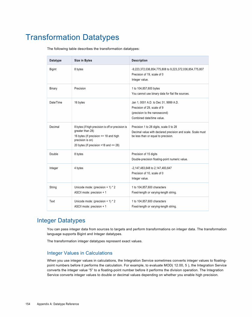
Transformation DatatypesThe following table describes the transformation datatypes:
Datatype Size in Bytes Description
Bigint 8 bytes -9,223,372,036,854,775,808 to 9,223,372,036,854,775,807Precision of 19, scale of 0Integer value.
Binary Precision 1 to 104,857,600 bytesYou cannot use binary data for flat file sources.
Date/Time 16 bytes Jan 1, 0001 A.D. to Dec 31, 9999 A.D.Precision of 29, scale of 9(precision to the nanosecond)Combined date/time value.
Decimal 8 bytes (if high precision is off or precision isgreater than 28)16 bytes (If precision <= 18 and highprecision is on)20 bytes (If precision >18 and <= 28)
Precision 1 to 28 digits, scale 0 to 28Decimal value with declared precision and scale. Scale mustbe less than or equal to precision.
Double 8 bytes Precision of 15 digitsDouble-precision floating-point numeric value.
Integer 4 bytes -2,147,483,648 to 2,147,483,647Precision of 10, scale of 0Integer value.
String Unicode mode: (precision + 1) * 2ASCII mode: precision + 1
1 to 104,857,600 charactersFixed-length or varying-length string.
Text Unicode mode: (precision + 1) * 2ASCII mode: precision + 1
1 to 104,857,600 charactersFixed-length or varying-length string.
Integer DatatypesYou can pass integer data from sources to targets and perform transformations on integer data. The transformationlanguage supports Bigint and Integer datatypes.
The transformation integer datatypes represent exact values.
Integer Values in CalculationsWhen you use integer values in calculations, the Integration Service sometimes converts integer values to floating-point numbers before it performs the calculation. For example, to evaluate MOD( 12.00, 5 ), the Integration Serviceconverts the integer value “5” to a floating-point number before it performs the division operation. The IntegrationService converts integer values to double or decimal values depending on whether you enable high precision.
154 Appendix A: Datatype Reference
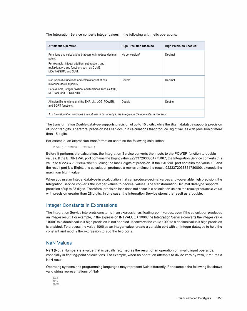
The Integration Service converts integer values in the following arithmetic operations:
Arithmetic Operation High Precision Disabled High Precision Enabled
Functions and calculations that cannot introduce decimalpoints.For example, integer addition, subtraction, andmultiplication, and functions such as CUME,MOVINGSUM, and SUM.
No conversion1 Decimal
Non-scientific functions and calculations that canintroduce decimal points.For example, integer division, and functions such as AVG,MEDIAN, and PERCENTILE.
Double Decimal
All scientific functions and the EXP, LN, LOG, POWER,and SQRT functions.
Double Double
1. If the calculation produces a result that is out of range, the Integration Service writes a row error.
The transformation Double datatype supports precision of up to 15 digits, while the Bigint datatype supports precisionof up to 19 digits. Therefore, precision loss can occur in calculations that produce Bigint values with precision of morethan 15 digits.
For example, an expression transformation contains the following calculation:
POWER( BIGINTVAL, EXPVAL )
Before it performs the calculation, the Integration Service converts the inputs to the POWER function to doublevalues. If the BIGINTVAL port contains the Bigint value 9223372036854775807, the Integration Service converts thisvalue to 9.22337203685478e+18, losing the last 4 digits of precision. If the EXPVAL port contains the value 1.0 andthe result port is a Bigint, this calculation produces a row error since the result, 9223372036854780000, exceeds themaximum bigint value.
When you use an Integer datatype in a calculation that can produce decimal values and you enable high precision, theIntegration Service converts the integer values to decimal values. The transformation Decimal datatype supportsprecision of up to 28 digits. Therefore, precision loss does not occur in a calculation unless the result produces a valuewith precision greater than 28 digits. In this case, the Integration Service stores the result as a double.
Integer Constants in ExpressionsThe Integration Service interprets constants in an expression as floating-point values, even if the calculation producesan integer result. For example, in the expression INTVALUE + 1000, the Integration Service converts the integer value“1000” to a double value if high precision is not enabled. It converts the value 1000 to a decimal value if high precisionis enabled. To process the value 1000 as an integer value, create a variable port with an Integer datatype to hold theconstant and modify the expression to add the two ports.
NaN ValuesNaN (Not a Number) is a value that is usually returned as the result of an operation on invalid input operands,especially in floating-point calculations. For example, when an operation attempts to divide zero by zero, it returns aNaN result.
Operating systems and programming languages may represent NaN differently. For example the following list showsvalid string representations of NaN:
nanNaNNaN%
Transformation Datatypes 155
NANNaNQNaNSqNaNsNaN1.#SNAN1.#QNAN
The Integration Service converts QNAN values to 1.#QNAN on Win64EMT platforms. 1.#QNAN is a validrepresentation of NaN.
Convert String Values to Integer ValuesWhen the Integration Service performs implicit conversion of a string value to an integer value, the string must containnumeric characters only. Any non-numeric characters result in a transformation row error. For example, you link astring port that contains the value “9,000,000,000,000,000,000.777” to a Bigint port. The Integration Service cannotconvert the string to a bigint value and returns an error.
Write Integer Values to Flat FilesWhen writing integer values to a fixed-width flat file, the file writer does not verify that the data is within range. Forexample, the file writer writes the result 3,000,000,000 to a target Integer column if the field width of the target columnis at least 13. The file writer does not reject the row because the result is outside the valid range for Integer values.
Binary DatatypeIf a mapping includes binary data, set the precision for the transformation binary datatype so that the IntegrationService can allocate enough memory to move the data from source to target.
You cannot use binary datatypes for flat file sources.
Date/Time DatatypeThe Date/Time datatype handles years from 1 A.D. to 9999 A.D. in the Gregorian calendar system. Years beyond9999 A.D. cause an error.
The Date/Time datatype supports dates with precision to the nanosecond. The datatype has a precision of 29 and ascale of 9. Some native datatypes have a smaller precision. When you import a source that contains datetime values,the import process imports the correct precision from the source column. For example, the Microsoft SQL ServerDatetime datatype has a precision of 23 and a scale of 3. When you import a Microsoft SQL Server source thatcontains Datetime values, the Datetime columns in the mapping source have a precision of 23 and a scale of 3.
The Integration Service reads datetime values from the source to the precision specified in the mapping source. Whenthe Integration Service transforms the datetime values, it supports precision up to 29 digits. For example, if you importa datetime value with precision to the millisecond, you can use the ADD_TO_DATE function in an Expressiontransformation to add nanoseconds to the date.
If you write a Date/Time value to a target column that supports a smaller precision, the Integration Service truncatesthe value to the precision of the target column. If you write a Date/Time value to a target column that supports a largerprecision, the Integration Service inserts zeroes in the unsupported portion of the datetime value.
156 Appendix A: Datatype Reference
Decimal and Double DatatypesYou can pass decimal and double data from sources to targets and perform transformations on decimal and doubledata. The transformation language supports the following datatypes:
¨ Decimal. Precision 1 to 28 digits, scale 0 to 28. You cannot use decimal values with scale greater than precision ora negative precision. Transformations display any range you assign to a Decimal datatype, but the IntegrationService supports precision only up to 28.
¨ Double. Precision of 15.
Decimal and Double Values in CalculationsThe transformation Decimal datatype supports precision of up to 28 digits and the Double datatype supports precisionof up to 15 digits. Precision loss can occur with either datatype in a calculation when the result produces a value with aprecision greater than the maximum.
If you disable high precision, the Integration Service converts decimal values to doubles. Precision loss occurs if thedecimal value has a precision greater than 15 digits. For example, you have a mapping with Decimal (20,0) thatpasses the number 40012030304957666903. If you disable high precision, the Integration Service converts thedecimal value to double and passes 4.00120303049577 x 10¹⁹.
To ensure precision of up to 28 digits, use the Decimal datatype and enable high precision. When you enable highprecision, the Integration Service processes decimal values as Decimal. Precision loss does not occur in a calculationunless the result produces a value with precision greater than 28 digits. In this case, the Integration Service stores theresult as a double. Do not use the Double datatype for data that you use in an equality condition, such as a lookup orjoin condition.
The following table lists how the Integration Service handles decimal values based on high precision configuration:
Port Datatype Precision High Precision Off High Precision On
Decimal 0-28 Double Decimal
Decimal Over 28 Double Double
When you enable high precision, the Integration Service converts numeric constants in any expression function toDecimal. If you do not enable high precision, the Integration Service converts numeric constants to Double.
To ensure the maximum precision for numeric values greater than 28 digits, truncate or round any large numbersbefore performing any calculations or transformations with the transformation functions.
Rounding Methods for Double ValuesDue to differences in system run-time libraries and the computer system where the database processes doubledatatype calculations, the results may not be as expected. The double datatype conforms to the IEEE 794 standard.Changes to database client library, different versions of a database or changes to a system run-time library affect thebinary representation of mathematically equivalent values. Also, many system run-time libraries implement the round-to-even or the symmetric arithmetic method. The round-to-even method states that if a number falls midway betweenthe next higher or lower number it round to the nearest value with an even least significant bit. For example, with theround-to-even method, 0.125 is rounded to 0.12. The symmetric arithmetic method rounds the number to next higherdigit when the last digit is 5 or greater. For example, with the symmetric arithmetic method 0.125 is rounded to 0.13and 0.124 is rounded to 0.12.
To provide calculation results that are less susceptible to platform differences, the Integration Service stores the 15significant digits of double datatype values. For example, if a calculation on Windows returns the number
Transformation Datatypes 157
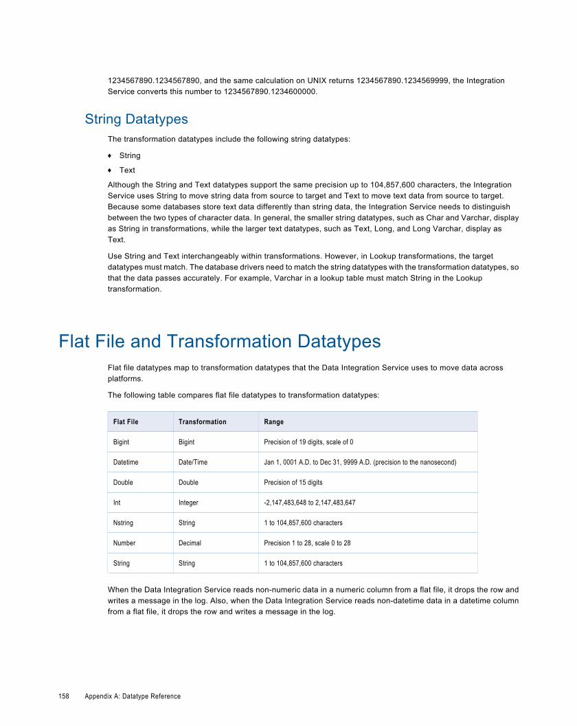
1234567890.1234567890, and the same calculation on UNIX returns 1234567890.1234569999, the IntegrationService converts this number to 1234567890.1234600000.
String DatatypesThe transformation datatypes include the following string datatypes:
¨ String
¨ Text
Although the String and Text datatypes support the same precision up to 104,857,600 characters, the IntegrationService uses String to move string data from source to target and Text to move text data from source to target.Because some databases store text data differently than string data, the Integration Service needs to distinguishbetween the two types of character data. In general, the smaller string datatypes, such as Char and Varchar, displayas String in transformations, while the larger text datatypes, such as Text, Long, and Long Varchar, display asText.
Use String and Text interchangeably within transformations. However, in Lookup transformations, the targetdatatypes must match. The database drivers need to match the string datatypes with the transformation datatypes, sothat the data passes accurately. For example, Varchar in a lookup table must match String in the Lookuptransformation.
Flat File and Transformation DatatypesFlat file datatypes map to transformation datatypes that the Data Integration Service uses to move data acrossplatforms.
The following table compares flat file datatypes to transformation datatypes:
Flat File Transformation Range
Bigint Bigint Precision of 19 digits, scale of 0
Datetime Date/Time Jan 1, 0001 A.D. to Dec 31, 9999 A.D. (precision to the nanosecond)
Double Double Precision of 15 digits
Int Integer -2,147,483,648 to 2,147,483,647
Nstring String 1 to 104,857,600 characters
Number Decimal Precision 1 to 28, scale 0 to 28
String String 1 to 104,857,600 characters
When the Data Integration Service reads non-numeric data in a numeric column from a flat file, it drops the row andwrites a message in the log. Also, when the Data Integration Service reads non-datetime data in a datetime columnfrom a flat file, it drops the row and writes a message in the log.
158 Appendix A: Datatype Reference
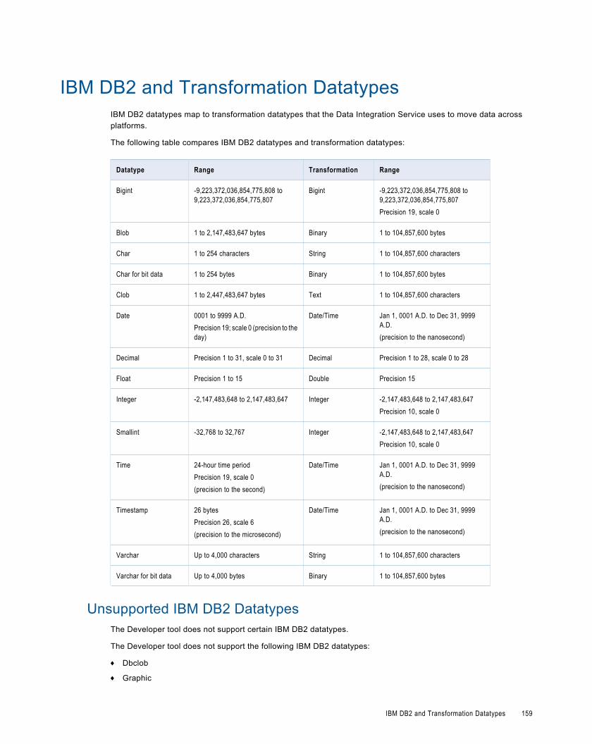
IBM DB2 and Transformation DatatypesIBM DB2 datatypes map to transformation datatypes that the Data Integration Service uses to move data acrossplatforms.
The following table compares IBM DB2 datatypes and transformation datatypes:
Datatype Range Transformation Range
Bigint -9,223,372,036,854,775,808 to9,223,372,036,854,775,807
Bigint -9,223,372,036,854,775,808 to9,223,372,036,854,775,807Precision 19, scale 0
Blob 1 to 2,147,483,647 bytes Binary 1 to 104,857,600 bytes
Char 1 to 254 characters String 1 to 104,857,600 characters
Char for bit data 1 to 254 bytes Binary 1 to 104,857,600 bytes
Clob 1 to 2,447,483,647 bytes Text 1 to 104,857,600 characters
Date 0001 to 9999 A.D.Precision 19; scale 0 (precision to theday)
Date/Time Jan 1, 0001 A.D. to Dec 31, 9999A.D.(precision to the nanosecond)
Decimal Precision 1 to 31, scale 0 to 31 Decimal Precision 1 to 28, scale 0 to 28
Float Precision 1 to 15 Double Precision 15
Integer -2,147,483,648 to 2,147,483,647 Integer -2,147,483,648 to 2,147,483,647Precision 10, scale 0
Smallint -32,768 to 32,767 Integer -2,147,483,648 to 2,147,483,647Precision 10, scale 0
Time 24-hour time periodPrecision 19, scale 0(precision to the second)
Date/Time Jan 1, 0001 A.D. to Dec 31, 9999A.D.(precision to the nanosecond)
Timestamp 26 bytesPrecision 26, scale 6(precision to the microsecond)
Date/Time Jan 1, 0001 A.D. to Dec 31, 9999A.D.(precision to the nanosecond)
Varchar Up to 4,000 characters String 1 to 104,857,600 characters
Varchar for bit data Up to 4,000 bytes Binary 1 to 104,857,600 bytes
Unsupported IBM DB2 DatatypesThe Developer tool does not support certain IBM DB2 datatypes.
The Developer tool does not support the following IBM DB2 datatypes:
¨ Dbclob
¨ Graphic
IBM DB2 and Transformation Datatypes 159
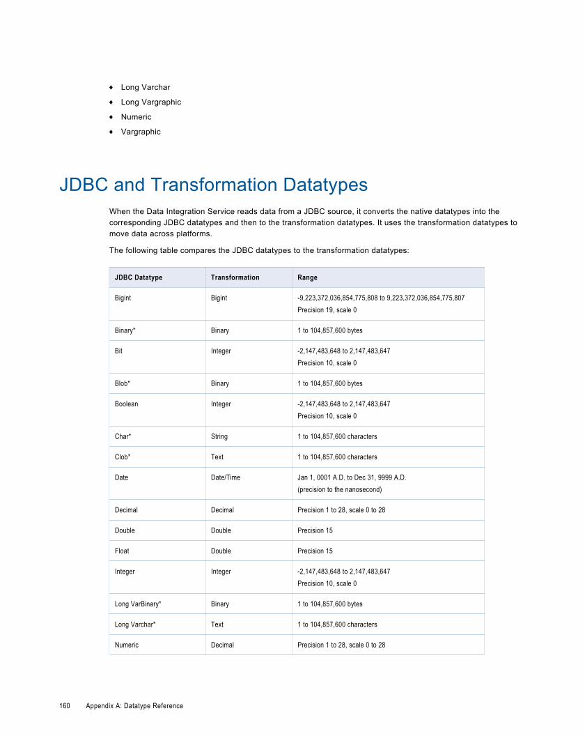
¨ Long Varchar
¨ Long Vargraphic
¨ Numeric
¨ Vargraphic
JDBC and Transformation DatatypesWhen the Data Integration Service reads data from a JDBC source, it converts the native datatypes into thecorresponding JDBC datatypes and then to the transformation datatypes. It uses the transformation datatypes tomove data across platforms.
The following table compares the JDBC datatypes to the transformation datatypes:
JDBC Datatype Transformation Range
Bigint Bigint -9,223,372,036,854,775,808 to 9,223,372,036,854,775,807Precision 19, scale 0
Binary* Binary 1 to 104,857,600 bytes
Bit Integer -2,147,483,648 to 2,147,483,647Precision 10, scale 0
Blob* Binary 1 to 104,857,600 bytes
Boolean Integer -2,147,483,648 to 2,147,483,647Precision 10, scale 0
Char* String 1 to 104,857,600 characters
Clob* Text 1 to 104,857,600 characters
Date Date/Time Jan 1, 0001 A.D. to Dec 31, 9999 A.D.(precision to the nanosecond)
Decimal Decimal Precision 1 to 28, scale 0 to 28
Double Double Precision 15
Float Double Precision 15
Integer Integer -2,147,483,648 to 2,147,483,647Precision 10, scale 0
Long VarBinary* Binary 1 to 104,857,600 bytes
Long Varchar* Text 1 to 104,857,600 characters
Numeric Decimal Precision 1 to 28, scale 0 to 28
160 Appendix A: Datatype Reference
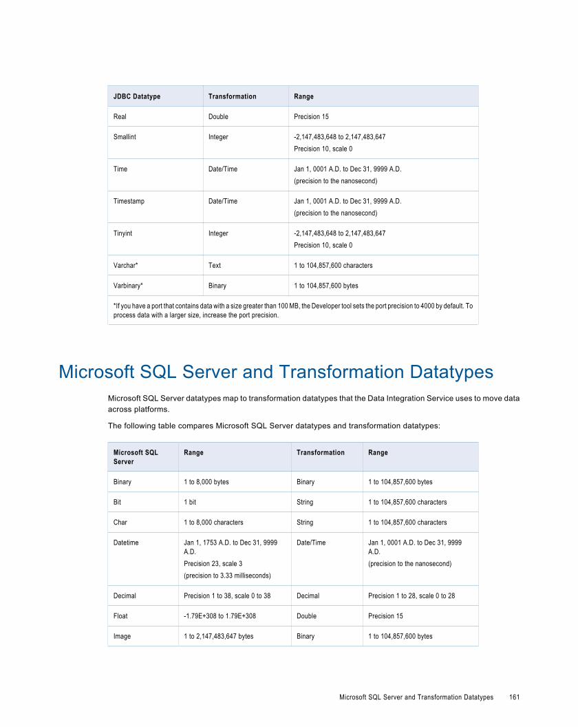
JDBC Datatype Transformation Range
Real Double Precision 15
Smallint Integer -2,147,483,648 to 2,147,483,647Precision 10, scale 0
Time Date/Time Jan 1, 0001 A.D. to Dec 31, 9999 A.D.(precision to the nanosecond)
Timestamp Date/Time Jan 1, 0001 A.D. to Dec 31, 9999 A.D.(precision to the nanosecond)
Tinyint Integer -2,147,483,648 to 2,147,483,647Precision 10, scale 0
Varchar* Text 1 to 104,857,600 characters
Varbinary* Binary 1 to 104,857,600 bytes
*If you have a port that contains data with a size greater than 100 MB, the Developer tool sets the port precision to 4000 by default. Toprocess data with a larger size, increase the port precision.
Microsoft SQL Server and Transformation DatatypesMicrosoft SQL Server datatypes map to transformation datatypes that the Data Integration Service uses to move dataacross platforms.
The following table compares Microsoft SQL Server datatypes and transformation datatypes:
Microsoft SQLServer
Range Transformation Range
Binary 1 to 8,000 bytes Binary 1 to 104,857,600 bytes
Bit 1 bit String 1 to 104,857,600 characters
Char 1 to 8,000 characters String 1 to 104,857,600 characters
Datetime Jan 1, 1753 A.D. to Dec 31, 9999A.D.Precision 23, scale 3(precision to 3.33 milliseconds)
Date/Time Jan 1, 0001 A.D. to Dec 31, 9999A.D.(precision to the nanosecond)
Decimal Precision 1 to 38, scale 0 to 38 Decimal Precision 1 to 28, scale 0 to 28
Float -1.79E+308 to 1.79E+308 Double Precision 15
Image 1 to 2,147,483,647 bytes Binary 1 to 104,857,600 bytes
Microsoft SQL Server and Transformation Datatypes 161
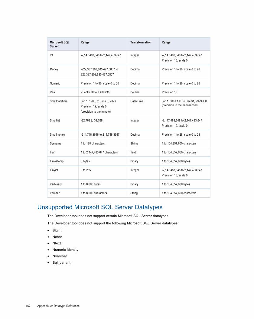
Microsoft SQLServer
Range Transformation Range
Int -2,147,483,648 to 2,147,483,647 Integer -2,147,483,648 to 2,147,483,647Precision 10, scale 0
Money -922,337,203,685,477.5807 to922,337,203,685,477.5807
Decimal Precision 1 to 28, scale 0 to 28
Numeric Precision 1 to 38, scale 0 to 38 Decimal Precision 1 to 28, scale 0 to 28
Real -3.40E+38 to 3.40E+38 Double Precision 15
Smalldatetime Jan 1, 1900, to June 6, 2079Precision 19, scale 0(precision to the minute)
Date/Time Jan 1, 0001 A.D. to Dec 31, 9999 A.D.(precision to the nanosecond)
Smallint -32,768 to 32,768 Integer -2,147,483,648 to 2,147,483,647Precision 10, scale 0
Smallmoney -214,748.3648 to 214,748.3647 Decimal Precision 1 to 28, scale 0 to 28
Sysname 1 to 128 characters String 1 to 104,857,600 characters
Text 1 to 2,147,483,647 characters Text 1 to 104,857,600 characters
Timestamp 8 bytes Binary 1 to 104,857,600 bytes
Tinyint 0 to 255 Integer -2,147,483,648 to 2,147,483,647Precision 10, scale 0
Varbinary 1 to 8,000 bytes Binary 1 to 104,857,600 bytes
Varchar 1 to 8,000 characters String 1 to 104,857,600 characters
Unsupported Microsoft SQL Server DatatypesThe Developer tool does not support certain Microsoft SQL Server datatypes.
The Developer tool does not support the following Microsoft SQL Server datatypes:
¨ Bigint
¨ Nchar
¨ Ntext
¨ Numeric Identity
¨ Nvarchar
¨ Sql_variant
162 Appendix A: Datatype Reference
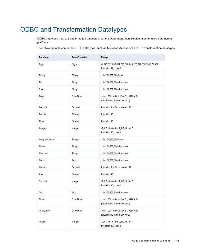
ODBC and Transformation DatatypesODBC datatypes map to transformation datatypes that the Data Integration Service uses to move data acrossplatforms.
The following table compares ODBC datatypes, such as Microsoft Access or Excel, to transformation datatypes:
Datatype Transformation Range
Bigint Bigint -9,223,372,036,854,775,808 to 9,223,372,036,854,775,807Precision 19, scale 0
Binary Binary 1 to 104,857,600 bytes
Bit String 1 to 104,857,600 characters
Char String 1 to 104,857,600 characters
Date Date/Time Jan 1, 0001 A.D. to Dec 31, 9999 A.D.(precision to the nanosecond)
Decimal Decimal Precision 1 to 28, scale 0 to 28
Double Double Precision 15
Float Double Precision 15
Integer Integer -2,147,483,648 to 2,147,483,647Precision 10, scale 0
Long Varbinary Binary 1 to 104,857,600 bytes
Nchar String 1 to 104,857,600 characters
Nvarchar String 1 to 104,857,600 characters
Ntext Text 1 to 104,857,600 characters
Numeric Decimal Precision 1 to 28, scale 0 to 28
Real Double Precision 15
Smallint Integer -2,147,483,648 to 2,147,483,647Precision 10, scale 0
Text Text 1 to 104,857,600 characters
Time Date/Time Jan 1, 0001 A.D. to Dec 31, 9999 A.D.(precision to the nanosecond)
Timestamp Date/Time Jan 1, 0001 A.D. to Dec 31, 9999 A.D.(precision to the nanosecond)
Tinyint Integer -2,147,483,648 to 2,147,483,647Precision 10, scale 0
ODBC and Transformation Datatypes 163
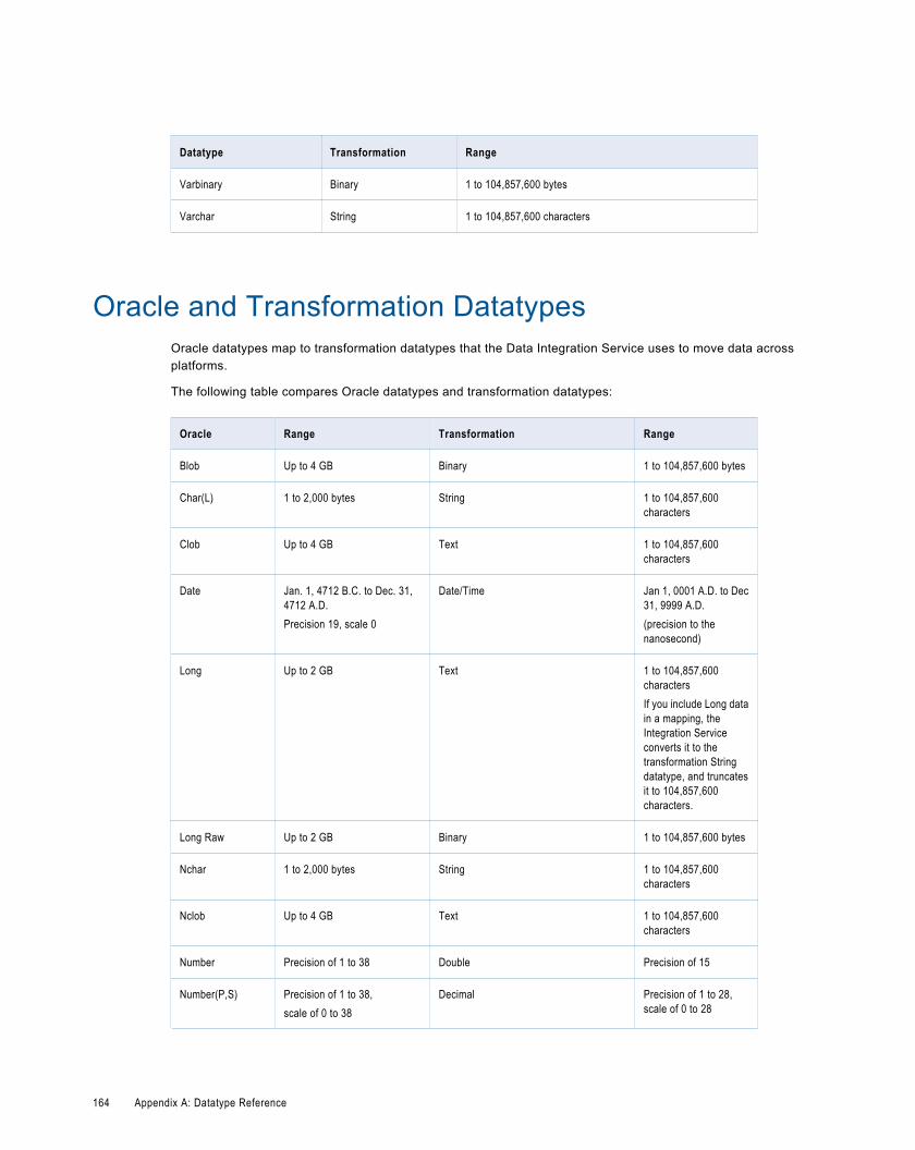
Datatype Transformation Range
Varbinary Binary 1 to 104,857,600 bytes
Varchar String 1 to 104,857,600 characters
Oracle and Transformation DatatypesOracle datatypes map to transformation datatypes that the Data Integration Service uses to move data acrossplatforms.
The following table compares Oracle datatypes and transformation datatypes:
Oracle Range Transformation Range
Blob Up to 4 GB Binary 1 to 104,857,600 bytes
Char(L) 1 to 2,000 bytes String 1 to 104,857,600characters
Clob Up to 4 GB Text 1 to 104,857,600characters
Date Jan. 1, 4712 B.C. to Dec. 31,4712 A.D.Precision 19, scale 0
Date/Time Jan 1, 0001 A.D. to Dec31, 9999 A.D.(precision to thenanosecond)
Long Up to 2 GB Text 1 to 104,857,600charactersIf you include Long datain a mapping, theIntegration Serviceconverts it to thetransformation Stringdatatype, and truncatesit to 104,857,600characters.
Long Raw Up to 2 GB Binary 1 to 104,857,600 bytes
Nchar 1 to 2,000 bytes String 1 to 104,857,600characters
Nclob Up to 4 GB Text 1 to 104,857,600characters
Number Precision of 1 to 38 Double Precision of 15
Number(P,S) Precision of 1 to 38,scale of 0 to 38
Decimal Precision of 1 to 28,scale of 0 to 28
164 Appendix A: Datatype Reference
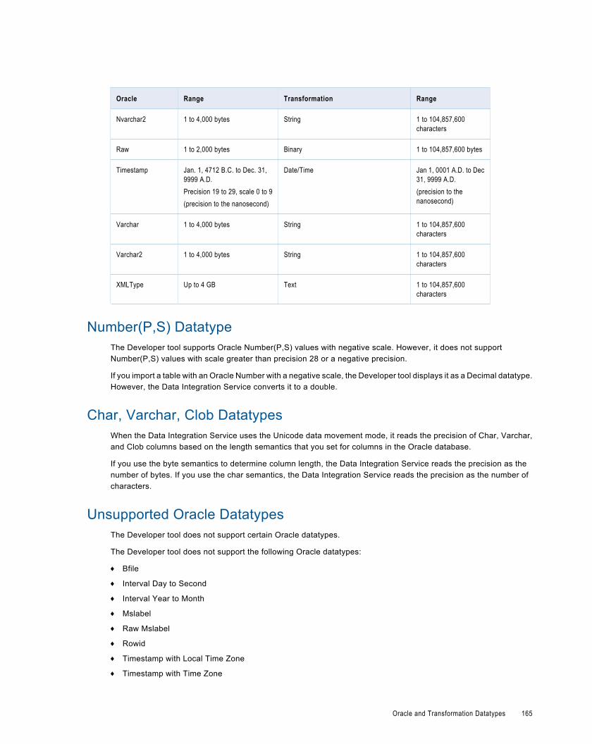
Oracle Range Transformation Range
Nvarchar2 1 to 4,000 bytes String 1 to 104,857,600characters
Raw 1 to 2,000 bytes Binary 1 to 104,857,600 bytes
Timestamp Jan. 1, 4712 B.C. to Dec. 31,9999 A.D.Precision 19 to 29, scale 0 to 9(precision to the nanosecond)
Date/Time Jan 1, 0001 A.D. to Dec31, 9999 A.D.(precision to thenanosecond)
Varchar 1 to 4,000 bytes String 1 to 104,857,600characters
Varchar2 1 to 4,000 bytes String 1 to 104,857,600characters
XMLType Up to 4 GB Text 1 to 104,857,600characters
Number(P,S) DatatypeThe Developer tool supports Oracle Number(P,S) values with negative scale. However, it does not supportNumber(P,S) values with scale greater than precision 28 or a negative precision.
If you import a table with an Oracle Number with a negative scale, the Developer tool displays it as a Decimal datatype.However, the Data Integration Service converts it to a double.
Char, Varchar, Clob DatatypesWhen the Data Integration Service uses the Unicode data movement mode, it reads the precision of Char, Varchar,and Clob columns based on the length semantics that you set for columns in the Oracle database.
If you use the byte semantics to determine column length, the Data Integration Service reads the precision as thenumber of bytes. If you use the char semantics, the Data Integration Service reads the precision as the number ofcharacters.
Unsupported Oracle DatatypesThe Developer tool does not support certain Oracle datatypes.
The Developer tool does not support the following Oracle datatypes:
¨ Bfile
¨ Interval Day to Second
¨ Interval Year to Month
¨ Mslabel
¨ Raw Mslabel
¨ Rowid
¨ Timestamp with Local Time Zone
¨ Timestamp with Time Zone
Oracle and Transformation Datatypes 165

XML and Transformation DatatypesXML datatypes map to transformation datatypes that the Data Integration Service uses to move data acrossplatforms.
The Data Integration Service supports all XML datatypes specified in the W3C May 2, 2001 Recommendation.However, the Data Integration Service may not support the entire XML value range. For more information about XMLdatatypes, see the W3C specifications for XML datatypes at http://www.w3.org/TR/xmlschema-2...
The following table compares XML datatypes to transformation datatypes:
Datatype Transformation Range
anyURI String 1 to 104,857,600 characters
base64Binary Binary 1 to 104,857,600 bytes
boolean String 1 to 104,857,600 characters
byte Integer -2,147,483,648 to 2,147,483,647
date Date/Time Jan 1, 0001 A.D. to Dec 31, 9999 A.D. (precision to the nanosecond)
dateTime Date/Time Jan 1, 0001 A.D. to Dec 31, 9999 A.D. (precision to the nanosecond)
decimal Decimal Precision 1 to 28, scale 0 to 28
double Double Precision of 15 digits
duration String 1 to 104,857,600 characters
ENTITIES String 1 to 104,857,600 characters
ENTITY String 1 to 104,857,600 characters
float Double Precision of 15 digits
gDay String 1 to 104,857,600 characters
gMonth String 1 to 104,857,600 characters
gMonthDay String 1 to 104,857,600 characters
gYear String 1 to 104,857,600 characters
gYearMonth String 1 to 104,857,600 characters
hexBinary Binary 1 to 104,857,600 bytes
ID String 1 to 104,857,600 characters
IDREF String 1 to 104,857,600 characters
IDREFS String 1 to 104,857,600 characters
int Integer -2,147,483,648 to 2,147,483,647
166 Appendix A: Datatype Reference
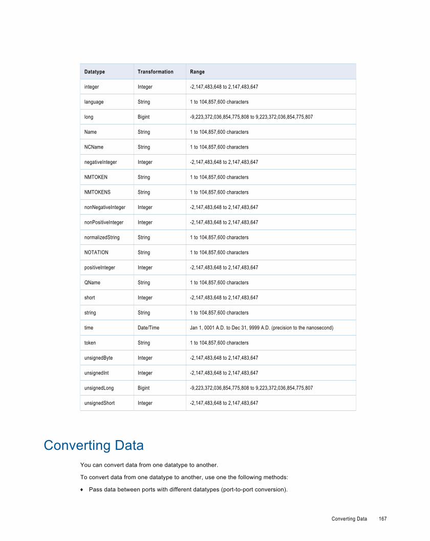
Datatype Transformation Range
integer Integer -2,147,483,648 to 2,147,483,647
language String 1 to 104,857,600 characters
long Bigint -9,223,372,036,854,775,808 to 9,223,372,036,854,775,807
Name String 1 to 104,857,600 characters
NCName String 1 to 104,857,600 characters
negativeInteger Integer -2,147,483,648 to 2,147,483,647
NMTOKEN String 1 to 104,857,600 characters
NMTOKENS String 1 to 104,857,600 characters
nonNegativeInteger Integer -2,147,483,648 to 2,147,483,647
nonPositiveInteger Integer -2,147,483,648 to 2,147,483,647
normalizedString String 1 to 104,857,600 characters
NOTATION String 1 to 104,857,600 characters
positiveInteger Integer -2,147,483,648 to 2,147,483,647
QName String 1 to 104,857,600 characters
short Integer -2,147,483,648 to 2,147,483,647
string String 1 to 104,857,600 characters
time Date/Time Jan 1, 0001 A.D. to Dec 31, 9999 A.D. (precision to the nanosecond)
token String 1 to 104,857,600 characters
unsignedByte Integer -2,147,483,648 to 2,147,483,647
unsignedInt Integer -2,147,483,648 to 2,147,483,647
unsignedLong Bigint -9,223,372,036,854,775,808 to 9,223,372,036,854,775,807
unsignedShort Integer -2,147,483,648 to 2,147,483,647
Converting DataYou can convert data from one datatype to another.
To convert data from one datatype to another, use one the following methods:
¨ Pass data between ports with different datatypes (port-to-port conversion).
Converting Data 167
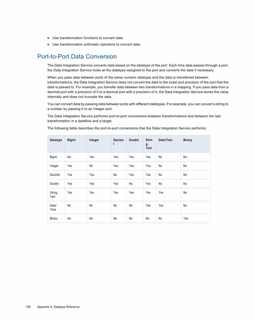
¨ Use transformation functions to convert data.
¨ Use transformation arithmetic operators to convert data.
Port-to-Port Data ConversionThe Data Integration Service converts data based on the datatype of the port. Each time data passes through a port,the Data Integration Service looks at the datatype assigned to the port and converts the data if necessary.
When you pass data between ports of the same numeric datatype and the data is transferred betweentransformations, the Data Integration Service does not convert the data to the scale and precision of the port that thedata is passed to. For example, you transfer data between two transformations in a mapping. If you pass data from adecimal port with a precision of 5 to a decimal port with a precision of 4, the Data Integration Service stores the valueinternally and does not truncate the data.
You can convert data by passing data between ports with different datatypes. For example, you can convert a string toa number by passing it to an Integer port.
The Data Integration Service performs port-to-port conversions between transformations and between the lasttransformation in a dataflow and a target.
The following table describes the port-to-port conversions that the Data Integration Service performs:
Datatype Bigint Integer Decimal
Double String,Text
Date/Time Binary
Bigint No Yes Yes Yes Yes No No
Integer Yes No Yes Yes Yes No No
Decimal Yes Yes No Yes Yes No No
Double Yes Yes Yes No Yes No No
String,Text
Yes Yes Yes Yes Yes Yes No
Date/Time
No No No No Yes Yes No
Binary No No No No No No Yes
168 Appendix A: Datatype Reference
I N D E X
Aabstract property
schema object 69application element
parameter files 141applications
creating 130mapping deployment properties 132redeploying 134replacing 133updating 132, 133
attribute propertiesschema object 72
attributeFormDefaultschema object 73
attributesrelationships 92
Bbase property
schema object 70bigint
constants in expressions 155high precision handling 154using in calculations 154writing to flat files 156
binary datatypesoverview 156
block propertyschema object 70
Ccertificates
adding untrusted certificates 65, 76certificate properties 65, 76managing certificates 64, 75untrusted certificates 64, 75
cheat sheetsdescription 5
collapse whitespace propertyschema object 70
column profileoptions 78overview 77process 78
column profile resultscolumn profile 80
complex typeadvanced properties 72
configurationstroubleshooting 151
connectionsConnection Explorer view 29creating 30deleting 21editing 21IBM DB2 properties 23JDBC properties 24Microsoft SQL Server properties 24ODBC properties 26Oracle properties 27overview 21renaming 21web services properties 27
copydescription 19objects 20
cost-based optimizationdescription 107
custom queriesInformatica join syntax 47left outer join syntax 48normal join syntax 47outer join support 47right outer join syntax 50
custom SQL queriescreating 41customized data objects 41
customized data objectsadding pre- and post-mapping SQL commands 50adding relational data objects 40adding relational resources 40advanced query 41creating 39creating a custom query 41creating key relationships 38creating keys 38custom SQL queries 41default query 41description 36entering source filters 44entering user-defined joins 46key relationships 37pre- and post-mapping SQL commands 50reserved words file 41select distinct 44simple query 41sorted ports 45troubleshooting 65user-defined joins 46using select distinct 44using sorted ports 45write properties 39
169
DData Integration Service
selecting 9data object profiles
creating a single profile 79data viewer
configuration properties 148configurations 146, 147creating configurations 147troubleshooting configurations 151
database hintsentering in Developer tool 43
datatypesBigint 154binary 156Date/Time 156decimal 157double 157flat file 158IBM DB2 159Integer 154JDBC 160Microsoft SQL Server 161ODBC 163Oracle 164overview 153port-to-port data conversion 168string 158transformation 154XML 166
Date/Time datatypesoverview 156
decimalhigh precision handling 154, 157
decimal datatypesoverview 157
default SQL queryviewing 41
dependenciesimplicit 101link path 101
deploymentmapping properties 132overview 129redeploying an application 134replacing applications 133to a Data Integration Service 131to file 131updating applications 133
Developer toolworkspace directory 2
doublehigh precision handling 157
double datatypesoverview 157
Eearly projection optimization
description 106early selection optimization
description 106elementFormDefault
schema object 73enumeration property
schema object 69
error messagesgrouping 19limiting 19
exportdependent objects 124objects 126overview 124XML file 125
expressionspushdown optimization 112
Ffind in editor
description 18fixed value property
schema object 69flat file data objects
advanced properties 58column properties 52configuring read properties 55configuring write properties 58creating 59delimited, importing 60description 51fixed-width, importing 60general properties 52read properties 52, 56
folderscreating 16description 16
full optimization leveldescription 105
functionsavailable in sources 112pushdown optimization 112
Ggenerated prefix
changing for namespace 68
Hhigh precision
Bigint datatype 154Decimal datatype 154
hintsQuery view 43
IIBM DB2 sources
pushdown optimization 111identifying relationships
description 92import
application archives 132dependent objects 124objects 127overview 124XML file 125
Informatica Developeroverview 1
170 Index
profile views 79setting up 5starting 2
Informatica Marketplacedescription 5
inherit by propertyschema object 71
inherit from propertyschema object 71
integersconstants in expressions 155converting from strings 156using in calculations 154writing to flat files 156
Jjoin syntax
customized data objects 47Informatica syntax 47left outer join syntax 48normal join syntax 47right outer join syntax 50
Kkey relationships
creating between relational data objects 35creating in customized data objects 38customized data objects 37relational data objects 34
Llocal workspace directory
configuring 2logical data object mappings
creating 94read mappings 93types 93write mappings 94
logical data object modelscreating 84description 84example 83importing 85
logical data objectsattribute relationships 92creating 93description 92example 83properties 92
logical view of datadeveloping 84overview 83
logsdescription 151
Mmapping object
running a profile 123mapping parameters
overview 135system 135
types 136user-defined 135, 136where to apply 138where to create 137
mappingsadding objects 97configuration properties 148configurations 146, 147connection validation 103creating 96creating configurations 148deployment properties 132developing 96expression validation 103object dependency 95object validation 103objects 97optimization methods 106overview 95predicate optimization method 107running 103troubleshooting configurations 151validating 103validation 102
Mapplet and Mapping ProfilingOverview 122
mappletscreating 120input 119output 119overview 118rules 119types 118validating 120
maximum lengthschema object 69
maximum occursschema object 69
member typesschema object 70
Microsoft SQL Server sourcespushdown optimization 111pushdown optimization 111
minimal optimization leveldescription 105
minimum lengthschema object 69
minimum occursschema object 69
Model repositoryconnecting 12description 10objects 10
monitoringdescription 152
Nnamespace
changing generated prefix 68namespaces
schema object 68NaN
described 155nillible property
schema object 69
Index 171
non-identifying relationshipsdescription 92
normal optimization leveldescription 105
Oobjects
copying 20operators
available in sources 116pushdown optimization 116
optimizationcost-based optimization method 107early projection optimization method 106early selection optimization method 106mapping performance methods 106semi-join optimization method 108
optimization levelsdescription 105
Oracle sourcespushdown optimization 111
outer join supportcustomized data objects 47
Pparameter files
application element 141creating 143mapping 135project element 140purpose 139running mappings with 139sample 141structure 139XML schema definition 139
parametersmapping 135
pattern propertyschema object 69
performance tuningcost-based optimization method 107creating data viewer configurations 147creating mapping configurations 148data viewer configurations 147early projection optimization method 106early selection optimization method 106mapping configurations 147optimization levels 105optimization methods 106predicate optimization method 107pushdown optimization 110semi-join optimization method 108
physical data objectscustomized data objects 36description 33flat file data objects 51relational data objects 34synchronization 65troubleshooting 65
port attributespropogating 100
portsconnection validation 103linking 98linking automatically 99
linking by name 99linking by position 99linking manually 98linking rules and guidelines 99propagated attributes by transformation 101
pre- and post-mapping SQL commandsadding to relational data objects 50customized data objects 50
primary keyscreating in customized data objects 38creating in relational data objects 35
profile resultsexporting in Informatica Developer 81
project elementparameter files 140
project permissionsallowing parent object access 15assigning 15dependent object instances 14external object permissions 14grant permission 13read permission 13showing security details 15write permission 13
projectsassigning permissions 15creating 12description 12filtering 13permissions 13sharing 12
pushdown optimizationexpressions 112functions 112IBM DB2 sources 111Microsoft SQL Server sources 111ODBC sources 111operators 116Oracle sources 111overview 110relational sources 111sources 111Sybase ASE sources 111
QQNAN
converting to 1.#QNAN 155Query view
configuring hints 43
Rread transformations
creating from relational data objects 35relational connections
adding to customized data objects 40relational data objects
adding to customized data objects 40creating key relationships 35creating keys 35creating read transformations 35description 34importing 36key relationships 34troubleshooting 65
172 Index
relational sourcespushdown optimization 111
reserved words filecreating 42customized data objects 41
rulesapplying in PowerCenter Express 122creating in Informatica Developer 121overview 78prerequisites 121
Sschema files
adding to schema objects 68editing 75removing from schema objects 68setting a default editor 74
schema objectelements advanced properties 70abstract property 69attribute properties 72attributeFormDefault 73block property 70complex elements 71complex elements advanced properties 72editing a schema file 73element properties 69elementFormDefault 73file location 73importing 73inherit by property 71inherit from property 71namespaces 68overview 67Overview view 67schema files 68setting a default editor 74simple type 70substitution group 70synchronization 73
Schema objectSchema view 68
Schema viewSchema object 68simple type advanced properties 71
searchdescription 16searching for objects and properties 17
select distinctcustomized data objects 44using in customized data objects 44
self-joinscustom SQL queries 41
semi-join optimizationdescription 108
simple typeschema object 71
SImple Type viewschema object 70
sorted portscustomized data objects 45using in customized data objects 45
source filtersentering 44
SQL hintsentering in Developer tool 43
string datatypesoverview 158
stringsconverting to numbers 156
substitution groupschema object 70
Sybase ASE sourcespushdown optimization 111
synchronizationcustomized data objects 65physical data objects 65
system parametersmapping 135
Ttransformation datatypes
list of 154
Uuser-defined joins
customized data objects 46entering 46Informatica syntax 47left outer join syntax 48normal join syntax 47outer join support 47right outer join syntax 50
user-defined parametersmapping 135
Vvalidation
configuring preferences 19grouping error messages 19limiting error messages 19
variety propertyschema object 70
viewsConnection Explorer view 29
Wweb service
configuration properties 148Welcome page
description 4workspace directory
configuring 2WSDL data objects
advanced view 63importing 62overview view 62schema view 62synchronization 63
Index 173
Recommended