Introduction to
Basic Electronics 8
Basic Electronics
• What is RF?
• Basic RF systems
• Basic RF test equipments
Basic Definition• RF (Radio frequency) is a frequency or rate of oscillation within
the range of about 3 Hz to 300 GHz.
• Since most of this range is beyond the vibration rate that most mechanicalsystems can respond to, RF usually refers to oscillations in electricalcircuits or electromagnetic radiation.
• Electrical currents that oscillate at RF have special properties not sharedby direct current signals.– One such property is the ease with which it can ionize air to create a
conductive path through air.– Another special property is an electromagnetic force that drives the RF
current to the surface of conductors, known as the skin effect which isuseful when designing RF circuits.
– Another property is the ability to appear to flow through paths thatcontain insulating material, like the dielectric insulator of a capacitor.
• The degree of effect of these properties depends on the frequency of thesignals.
RF Terminology• Hertz (Hz)
– A term representing cycles/second (cps).– The unit of measure is named after Heinrich Hertz, German physicist.– For example, 1 Hz means that an event repeats once per second, 2 Hz is
twice per second, and so on.
• Frequency– The number of occurrences of a repeating event per unit time.– For example:
* The frequency of the standard pitch A above middle C on a piano is usually defined as 440 Hz, (440 cps).
* In North America the frequency of the alternating current (AC) is 60 Hz.
* Visible light from deep red to violet has frequencies of 430 to 750 THz(Terahertz).
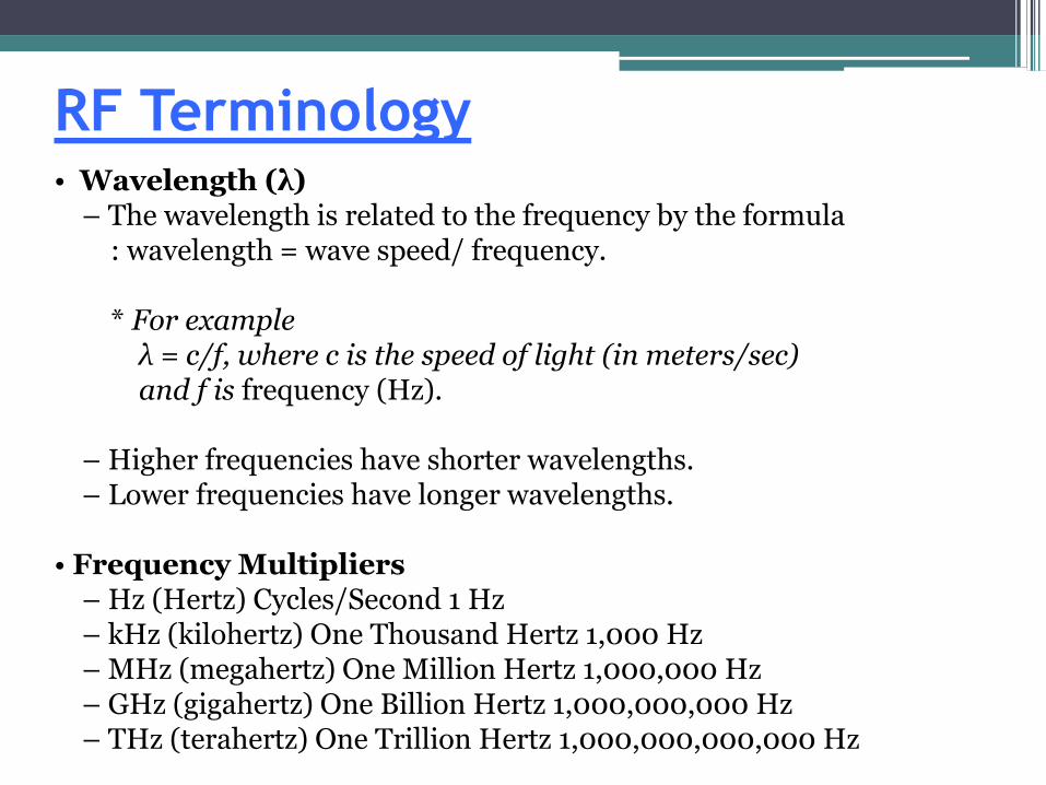
RF Terminology• Wavelength (λ)
– The wavelength is related to the frequency by the formula: wavelength = wave speed/ frequency.
* For exampleλ = c/f, where c is the speed of light (in meters/sec) and f is frequency (Hz).
– Higher frequencies have shorter wavelengths.– Lower frequencies have longer wavelengths.
• Frequency Multipliers– Hz (Hertz) Cycles/Second 1 Hz– kHz (kilohertz) One Thousand Hertz 1,000 Hz– MHz (megahertz) One Million Hertz 1,000,000 Hz– GHz (gigahertz) One Billion Hertz 1,000,000,000 Hz– THz (terahertz) One Trillion Hertz 1,000,000,000,000 Hz
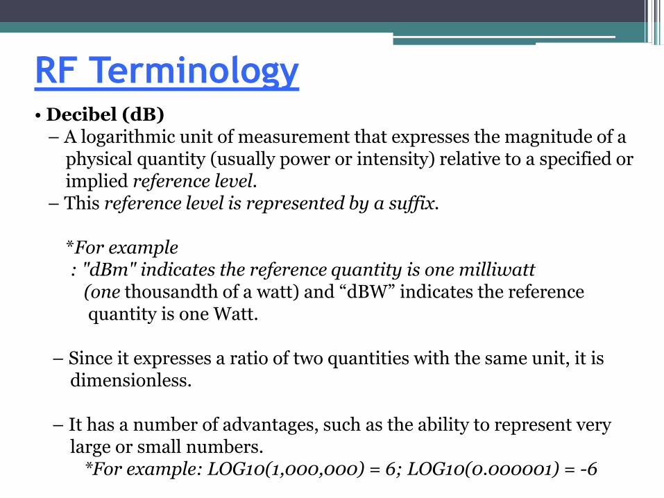
RF Terminology• Decibel (dB)
– A logarithmic unit of measurement that expresses the magnitude of a physical quantity (usually power or intensity) relative to a specified or implied reference level.
– This reference level is represented by a suffix.
*For example: "dBm" indicates the reference quantity is one milliwatt
(one thousandth of a watt) and “dBW” indicates the reference quantity is one Watt.
– Since it expresses a ratio of two quantities with the same unit, it is dimensionless.
– It has a number of advantages, such as the ability to represent very large or small numbers.
*For example: LOG10(1,000,000) = 6; LOG10(0.000001) = -6
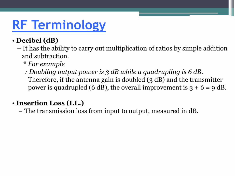
RF Terminology• Decibel (dB)
– It has the ability to carry out multiplication of ratios by simple addition and subtraction.* For example: Doubling output power is 3 dB while a quadrupling is 6 dB.
Therefore, if the antenna gain is doubled (3 dB) and the transmitter power is quadrupled (6 dB), the overall improvement is 3 + 6 = 9 dB.
• Insertion Loss (I.L.)– The transmission loss from input to output, measured in dB.
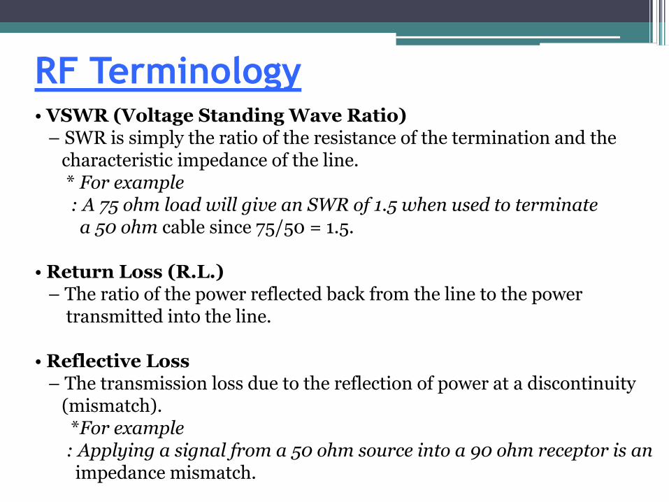
RF Terminology• VSWR (Voltage Standing Wave Ratio)
– SWR is simply the ratio of the resistance of the termination and thecharacteristic impedance of the line.* For example: A 75 ohm load will give an SWR of 1.5 when used to terminate
a 50 ohm cable since 75/50 = 1.5.
• Return Loss (R.L.)– The ratio of the power reflected back from the line to the power
transmitted into the line.
• Reflective Loss– The transmission loss due to the reflection of power at a discontinuity
(mismatch).*For example
: Applying a signal from a 50 ohm source into a 90 ohm receptor is animpedance mismatch.
RF Terminology• Watt
– It measures the rate of energy conversion.– Using the units of ampere and volt, work (energy) is done at a rate of
one watt when one ampere flows through a potential difference of one volt.*For Example
: 1 watt = 1A x 1V; 120VAC applied to a 100W bulb draws 0.833 A
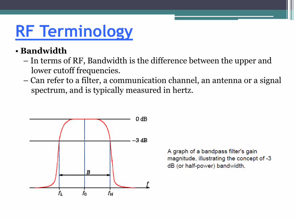
RF Terminology• Bandwidth
– In terms of RF, Bandwidth is the difference between the upper and lower cutoff frequencies.
– Can refer to a filter, a communication channel, an antenna or a signal spectrum, and is typically measured in hertz.
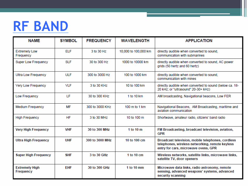
RF BAND
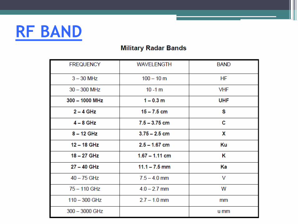
RF BAND
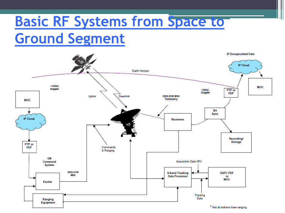
Basic RF Systems from Space to
Ground Segment
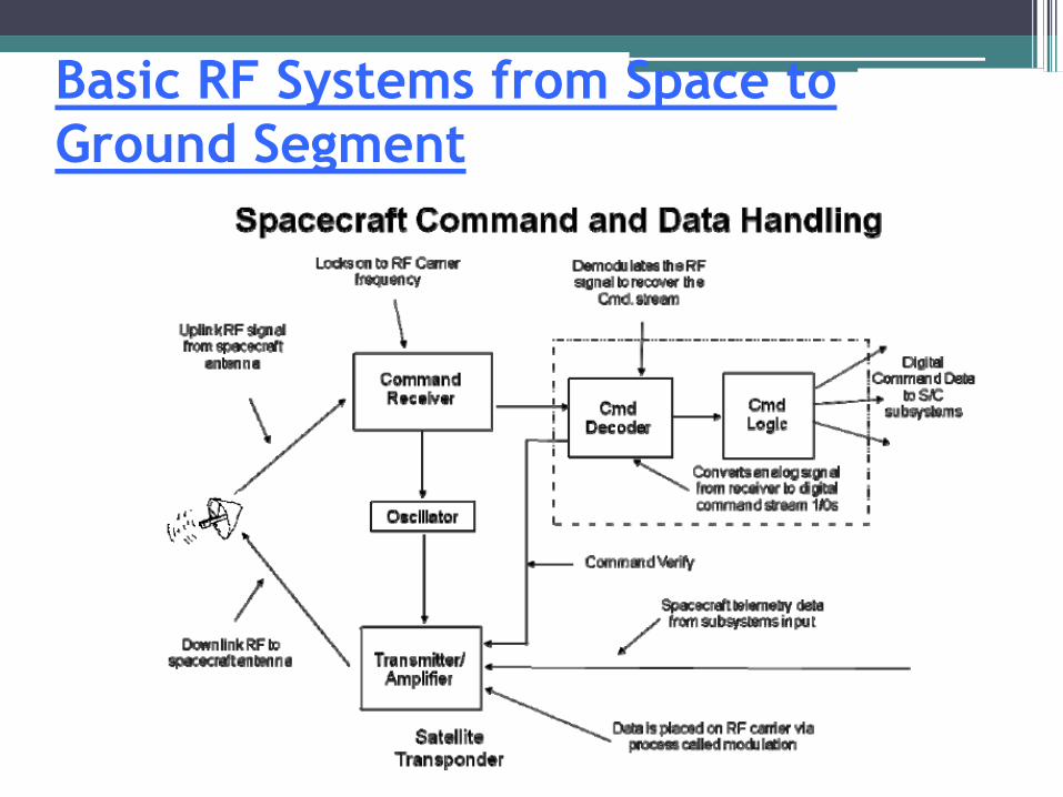
Basic RF Systems from Space to
Ground Segment
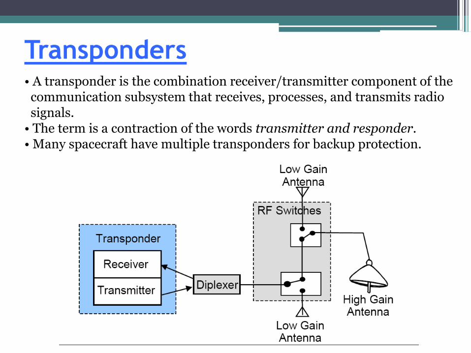
Transponders• A transponder is the combination receiver/transmitter component of the communication subsystem that receives, processes, and transmits radio signals.
• The term is a contraction of the words transmitter and responder.• Many spacecraft have multiple transponders for backup protection.
Transponder• The transmitter and receiver are co-located in one unit and can be phase coherent with one another such that the transmit (downlink) carrier source is derived from and is phase coherent with the received (uplink) carrier from the ground station.– This coherency allows precise estimations of orbit and speed from
measurements of Doppler offset and rate of the downlink frequency at the ground station.
• The XPNDR receives and detects digital command signals that control and configure the spacecraft.
• The XPNDR transmits telemetered data from the spacecraft data subsystem which can contain health status and science data.
• The XPNDR demodulates the ranging signal contained in the uplink and re-modulates it onto the downlink.– Thus, by measuring the return propagation time, the distance between
the ground station and the satellite can be calculated.
Transceivers
• Short for transmitter-receiver, a device that both transmits and receives analog or digital signals.
• In radio communications, a transceiver is a two-way radio that combines both a radio transmitter and a receiver that exchanges information in half-duplex mode.
• The transmit frequency may be some ratio of the receive frequency but they are not phase coherent with one another.
• Ranging and two way doppler cannot be performed when a spacecraft uses a transceiver as its radio, but one way dopplercan be performed.
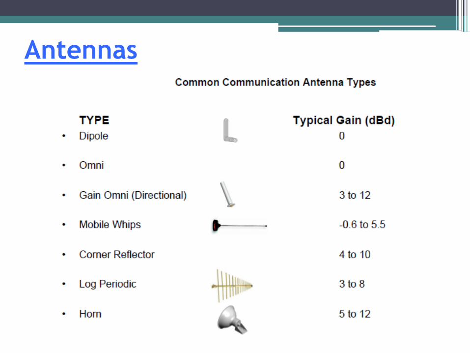
Antennas
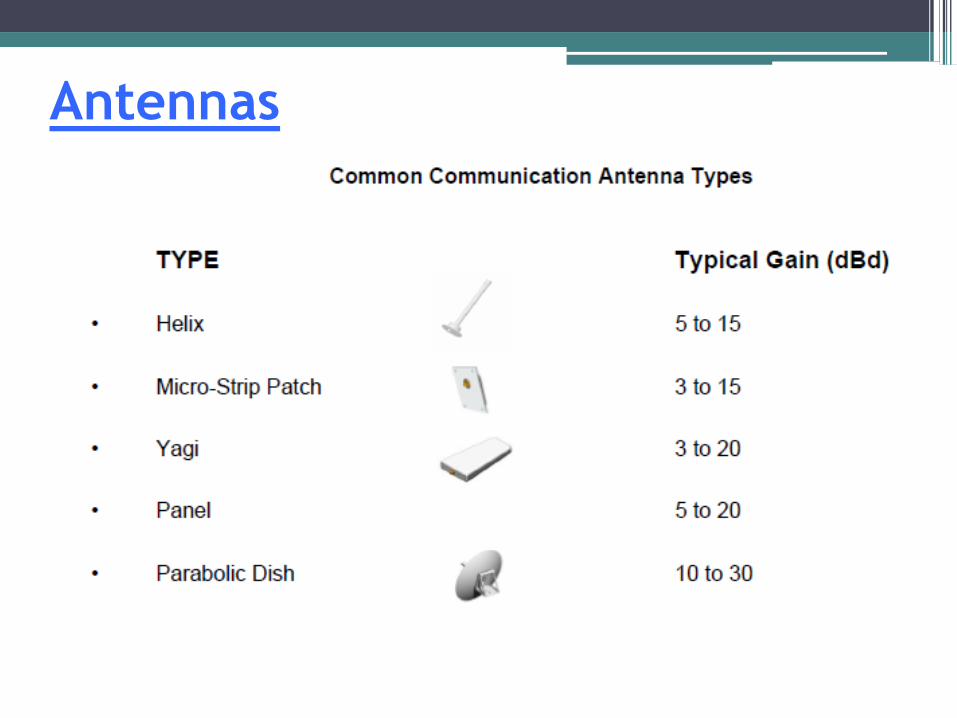
Antennas
Antennas• Gain– Antenna performance is primarily established by its gain.– Gain must always be measured against a know reference.– Unfortunately, there are many "so-called" gain references.–Choosing the wrong reference could cost you up to 2.0 dB in
performance.– Most commercial antenna suppliers specify gain in dBd
(gain over a half-wave dipole).
• The half-wave dipole has a very predictable radiation pattern similar tothat of a donut.– Another reference, especially at microwave frequencies, is dBi.
• This term refers to gain over an isotropic radiator, a theoretical antennathat radiates equally well in all directions (such as the Sun).
Antennas
• If an antenna is specified in dBi gain, it will appear to haveapproximately 2.15 dB higher gain than dBd.
• This may be a nifty way to impress the customer but it does not mean thatyou get more gain if dBi is the reference.– Beware if the supplier only quotes antenna gain in just "dB".
What is the reference?For instance, some mobile antennas are specified in dB gain over a
quarter wave whip which is about 0.6 dB less gain than a dipole.
Antennas
• VSWR (voltage-standing-wave-ratio) represents the degree with which an antenna is "matched" to the system impedance.
– Most modern antennas, receivers and transmitters are designed for peakperformance when operating into a 50 Ohm transmission line.
– If the VSWR is too high, the transmitter power may be reduced as well as the strength of the received signal.
– The typical commercial standard for maximum allowable VSWR across the entire bandwidth of a system is 1.5:1.
– You should specify the maximum VSWR and the operating frequency bandwidth when specifying your antenna.
– A VSWR of 2:1 or greater usually is considered unacceptable since it increases losses in the transmission line.
– Incidentally, decreasing the VSWR below 1.5:1 will often be expensive and will have little noticeable improvement.
Antennas
• Radiation Patterns– A graphical depiction of the relative field strength transmitted from or
received by the antenna.– Antenna radiation patterns are taken at one frequency, one polarization,
and one plane cut.
• plots in the plane of the axis is the azimuth or "E-plane"
• plots in the plane perpendicular to the axis is the elevation or "H-plane“– The patterns are usually presented in polar or rectilinear form with a dB
strength scale.– Patterns are normalized to the maximum graph value, 0 dB, and a
directivity is given for the antenna.
Antennas
• This means that if the side lobe level from the radiation pattern were down -13 dB, and the directivity of the antenna was 4 dB, then the sidelobe gain would be -9 dB.– Three types of plotting scales are in common usage; linear, linear
logarithmic and modified logarithmic.
Antennas
• Another popular antenna specification is the "front-to-back" (F/B) ratio.– It is defined as the difference in dB between the maximum gain or front
of the antenna (usually 0 degrees) and a point exactly 180 degrees behind the front.
• Another important antenna parameter is the side and rear lobe levels (if any).
– In a well designed antenna they should typically be 10-15 dB below the main beam.
– This parameter is often important but seldom seen on data sheets.– A good logarithmic plot will easily show such lobes and the direction
where they are maximum.
• Antenna plots will assist in the proper aiming of the antenna for optimum performance on all the desired signals.
• The narrower the beamwidth, the greater the difficulty in properly aiming the antenna.
Antennas
• Antenna Polarization– Most communications systems use either vertical, horizontal or circular
polarization.– Knowing the difference between polarizations and how to maximize their
benefit is very important to the antenna user.– A linear polarized antenna radiates wholly in one plane containing the
direction of propagation. – A circular polarized wave radiates energy in both the horizontal and
vertical planes and all planes in between.
• The difference, if any, between the maximum and the minimum peaks as the antenna is rotated through all angles, is called the axial ratio or ellipticity and is usually specified in decibels (dB).
Antennas
• If the axial ratio is near 0 dB, the antenna is said to be circular polarized. If the axial ratio is greater than 1-2 dB, the polarization is often referred to as elliptical.– In a circular polarized antenna, the plane of polarization rotates in a
circle making one complete revolution during one period of the wave.
• If the rotation is clockwise looking in the direction of propagation, the sense is called right-hand-circular (RHC).
• If the rotation is counterclockwise, the sense is called left-hand-circular (LHC).
Antennas
• Polarization (continued)– An antenna is said to be vertically polarized (linear) when its electric
field is perpendicular to the Earth's surface.
• An example of a vertical antenna is a broadcast tower for AM radio or the "whip"antenna on an automobile.– Horizontally polarized (linear) antennas have their electric field parallel
to the Earth's surface.
Antennas
• Television transmissions in the USA use horizontal polarization.
– Maximum signal strength between stations occurs when both stations are using identical polarization.
– In a linearly polarized system, a misalignment of polarization of 45 degrees will degrade the signal up to 3 dB and if misaligned 90 degrees the attenuation can be 20dB or more.
– Likewise, in a circular polarized system, both antennas must have the same sense. If not, an additional loss of 20 dB or more will be incurred.
– Also note that linearly polarized antennas will work with circularly polarized antennas and vice versa. However, there will be up to a 3 dB loss in signal strength.
– Circular polarization is most often used for satellite communications.
Transmission Line
• Transmission lines are a very important part of a communications system.• They carry RF signals from one place to another.
• Transmission lines are used to interconnect antennas and receivers/transmitters, and interconnect computers in a network.
• The flow of RF through a transmission line is very different from the flow of DC along a pair of wires.
• It is possible for a transmission line that is open-circuited at one end to look like a short circuit at the other end and in general, the impedance one measures at the input of a transmission line is dependent not only on theload placed at the far end of the line, but also on the electrical length of the line.
• It is these unusual properties that make transmission lines more than just a pair of wires.
Transmission Line
• Transmission lines are a very important part of a communications system.• They carry RF signals from one place to another.
• Transmission lines are used to interconnect antennas and receivers/transmitters, and interconnect computers in a network.
• The flow of RF through a transmission line is very different from the flow of DC along a pair of wires.
• It is possible for a transmission line that is open-circuited at one end to look like a short circuit at the other end and in general, the impedance one measures at the input of a transmission line is dependent not only on theload placed at the far end of the line, but also on the electrical length of the line.
Transmission Line
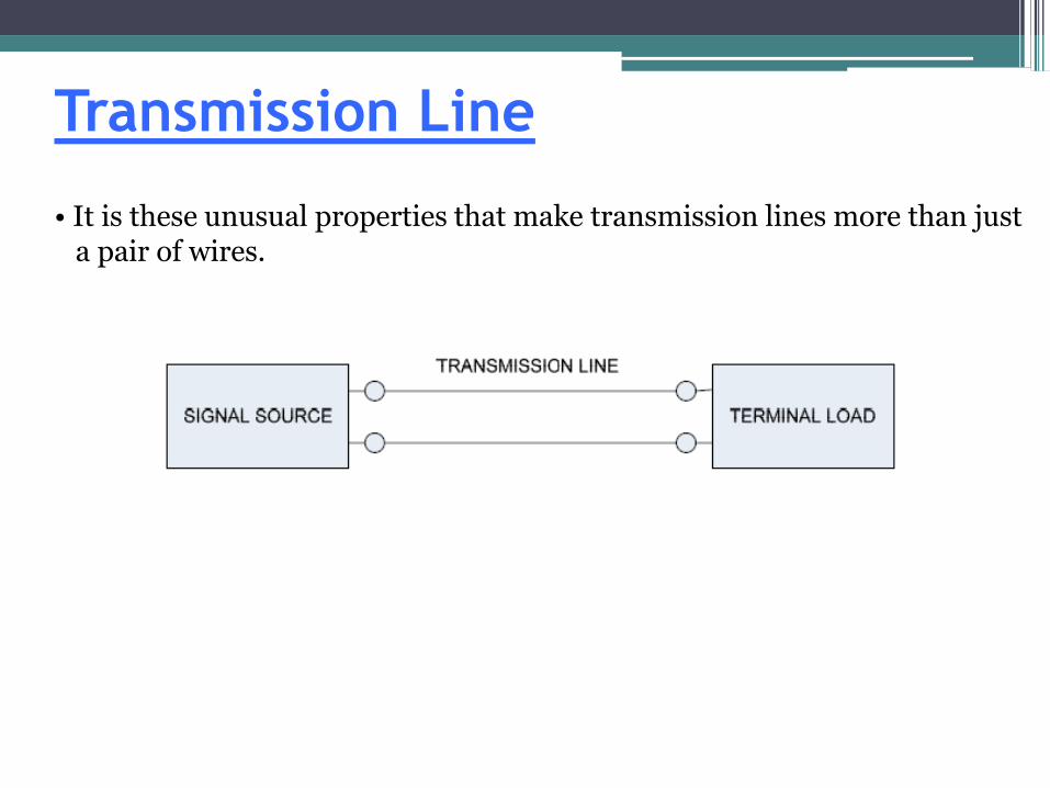
• It is these unusual properties that make transmission lines more than just a pair of wires.
Transmission Line• Types of transmission lines:– The simplest type of transmission line consists of two conductors
separated by a small distance.: This type of transmission line is called parallel line, open wire line, or
ladder line.– Another type of two wire transmission line consists of two parallel
wires embedded in an insulating material (typically polyethylene).: This type of transmission line is called twin-lead, and is very
similar to open wire line.
– Another type of two wire line is called unshielded twisted pair(UTP).It consists of two wires twisted around one another. The most commontype of UTP is CAT5 network cable. It consists of 4 UTP’s in a commonsheath.
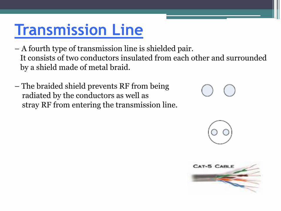
Transmission Line– A fourth type of transmission line is shielded pair.
It consists of two conductors insulated from each other and surroundedby a shield made of metal braid.
– The braided shield prevents RF from beingradiated by the conductors as well asstray RF from entering the transmission line.
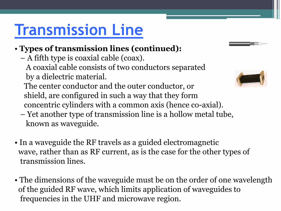
Transmission Line• Types of transmission lines (continued):
– A fifth type is coaxial cable (coax). A coaxial cable consists of two conductors separated by a dielectric material.
The center conductor and the outer conductor, or shield, are configured in such a way that they form concentric cylinders with a common axis (hence co-axial).
– Yet another type of transmission line is a hollow metal tube,known as waveguide.
• In a waveguide the RF travels as a guided electromagneticwave, rather than as RF current, as is the case for the other types of transmission lines.
• The dimensions of the waveguide must be on the order of one wavelength of the guided RF wave, which limits application of waveguides to frequencies in the UHF and microwave region.
Transmission Line• Flexible (Braided) Coaxial Cable is by far the most common type of
closed transmission line because of its flexibility.
– This type of cable is used in practically all applications requiring complete shielding of the center conductor.
– The effectiveness of the shielding depends upon the weave of the braid and the number of braid layers.
– One of the draw-backs of braided cable is that the shielding is not 100% effective, especially at higher frequencies. This is because the braided construction can permit small amounts of short wavelength (high frequency) energy to radiate.
– Normally this does not present a problem; however, if a higher degree of shielding is required, semi-rigid coaxial cable is recommended.
Transmission Line– In some high frequency flexible coaxial cables the outer shield consists if
normal braids and an extra aluminum foil shield to give better highfrequency shielding.
• Semi-rigid Coaxial Cable uses a solid tubular outer conductor, so that allthe RF energy is contained within the cable. For applications usingfrequencies higher than 30 GHz a miniature semi-rigid cable isrecommended.
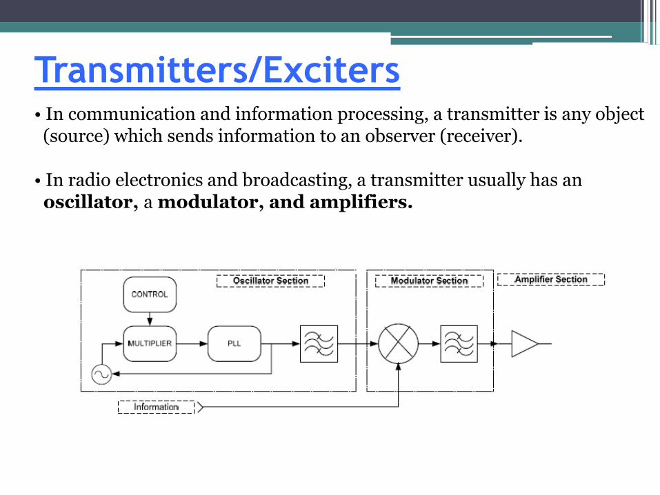
Transmitters/Exciters• In communication and information processing, a transmitter is any object (source) which sends information to an observer (receiver).
• In radio electronics and broadcasting, a transmitter usually has an oscillator, a modulator, and amplifiers.
Transmitters/Exciters• A crystal oscillator is generally used because of its ability to provide a very stable reference for generating the transmitter’s signal.– The oscillator is then multiplied up to the desired transmit frequency.
• The signal then gets modulated by commands or data.– The information is either modulated directly onto the transmit signal
(called the carrier) or it is first modulated on a subcarrier and then onto the transmit signal.
• For the transmit signal to be at a sufficient level the final stage of the transmitter is an amplifier.
Transmitters/Exciters• There are several modulation methods used.
• Analog modulation– Amplitude Modulation (AM)
: AM works by varying the strength of the transmitted signal in relation to the information being sent.
– Single-Sideband (SSB): A refinement of amplitude modulation that more efficiently uses
electrical power and bandwidth.
– Frequency Modulation (FM): Conveys information over a carrier wave by varying its frequency.
The instantaneous frequency of the carrier is directly proportional to theinstantaneous value of the input signal.
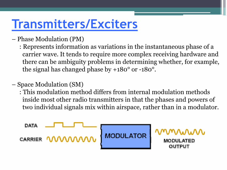
Transmitters/Exciters– Phase Modulation (PM)
: Represents information as variations in the instantaneous phase of a carrier wave. It tends to require more complex receiving hardware andthere can be ambiguity problems in determining whether, for example, the signal has changed phase by +180° or -180°.
– Space Modulation (SM): This modulation method differs from internal modulation methods
inside most other radio transmitters in that the phases and powers of two individual signals mix within airspace, rather than in a modulator.
Transmitters/Exciters• Digital Modulation
– On-off Keying (OOK): Represents digital data as the presence or absence of a carrier wave.
– Frequency Shift Keying (FSK): Digital information is transmitted through discrete frequency changes of a carrier wave. With this scheme, the "1" is called the mark frequency and the "0" is called the space frequency.
– Amplitude Shift Keying (ASK): Represents digital data as variations in the amplitude of a carrier wave.
– Phase Shift Keying (PSK): Conveys data by changing, or modulating, the phase of a reference
signal (the carrier wave).
Transmitters/Exciters• Various forms of PSK are:– DPSK: Differential Phase Shift Keying– BPSK: Binary Phase Shift Keying– QPSK: Quadrature Phase Shift Keying– OQPSK: Offset Quadrature Phase Shift Keying– Quadrature Amplitude Modulation (QAM)
: Conveys data by changing (modulating)the amplitude of two carrier waves. These two waves, usually sinusoids, are out of phase with eachother by 90º and are thus called quadrature carriers.
Transmitters/Exciters• Spread Spectrum– Frequency Hopping Spread Spectrum (FHSS): A method of transmitting
radio signals by rapidly switching a carrier among many frequency channels, using a pseudorandom sequence known to both transmitter and receiver.
– Direct Sequence Spread Spectrum (DSSS): Phase modulation of a sine wave with a continuous string of pseudo-noise (PN) code symbols called
"chips", each of which has a much shorter duration than an information bit.
• That is, each information bit is modulated by a sequence of much faster chips. Therefore, the chip rate is much higher than the information bit rate.
Transmitters/Exciters
• It uses a signal structure in which the sequence of chips produced by thetransmitter is known a priori by the receiver.
• The receiver can then use the same PN sequence to counteract the effect of the PN sequence on the received signal in order to reconstruct the information signal.
Amplifier
• An amplifier, or simply amp, is any device that changes, usually increases, the amplitude of a signal.
• Some types of Amplifiers:– Power Amplifier (PA): In general a power amplifier is
designated as the last amplifier in a transmission chain (the output stage).
– Types of PAs:* Solid State Power Amp (SSPA) Is the most common used
because of its compact size.* Traveling-Wave Tube Amplifier (TWTA) is an electronic
device used to amplify radio frequency signals to high power. The bandwidth of a broadband TWT can be as high as three octaves, although tuned (narrowband) versions exist, and operating frequencies range from 300 MHz to 50 GHz.
Amplifier
• Klystron is a specialized linear-beam vacuum tube (evacuated electron tube).
Klystrons are used as amplifiers at microwave and radio frequencies to produce high-power carrier waves for space communications.– Low Noise Amplifier (LNA)
: This is generally the first amplification of a receivedsignal from the antenna.
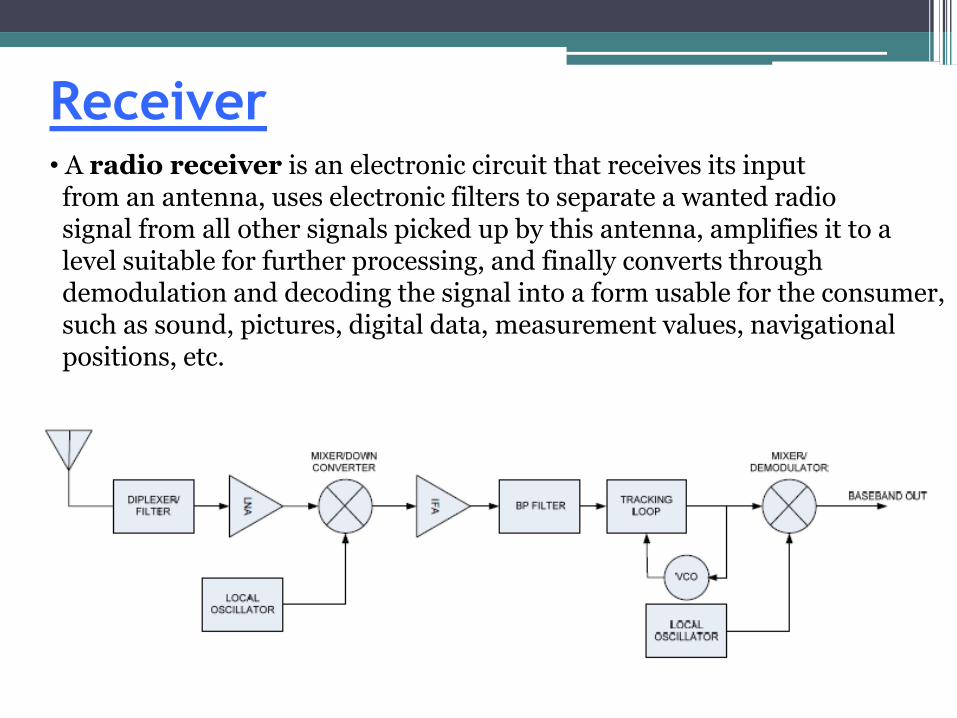
Receiver• A radio receiver is an electronic circuit that receives its input from an antenna, uses electronic filters to separate a wanted radio signal from all other signals picked up by this antenna, amplifies it to a level suitable for further processing, and finally converts throughdemodulation and decoding the signal into a form usable for the consumer, such as sound, pictures, digital data, measurement values, navigational positions, etc.
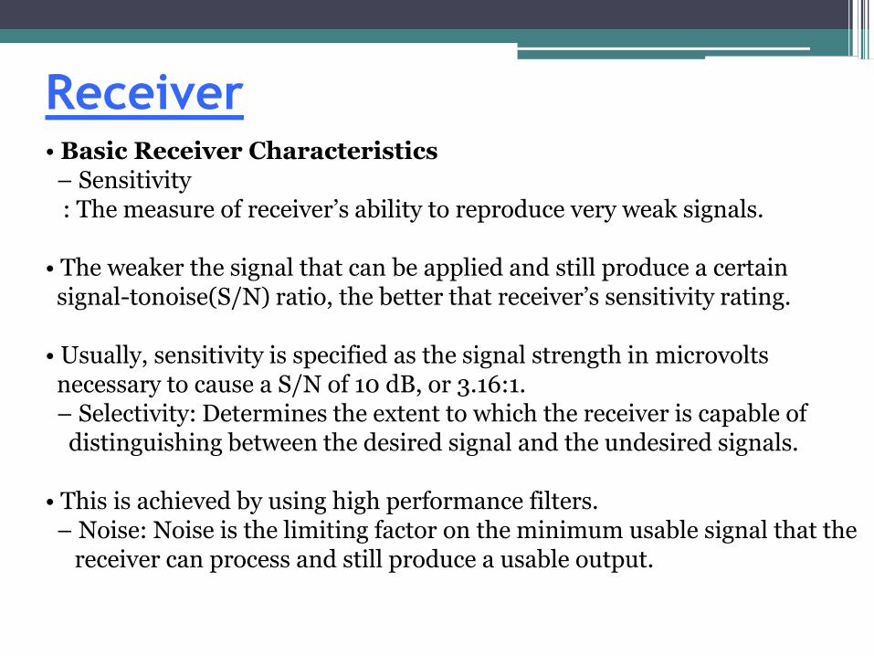
Receiver• Basic Receiver Characteristics– Sensitivity: The measure of receiver’s ability to reproduce very weak signals.
• The weaker the signal that can be applied and still produce a certain signal-tonoise(S/N) ratio, the better that receiver’s sensitivity rating.
• Usually, sensitivity is specified as the signal strength in microvoltsnecessary to cause a S/N of 10 dB, or 3.16:1.– Selectivity: Determines the extent to which the receiver is capable of
distinguishing between the desired signal and the undesired signals.
• This is achieved by using high performance filters.– Noise: Noise is the limiting factor on the minimum usable signal that the
receiver can process and still produce a usable output.
Receiver• Basic Receiver Characteristics- Expressed in decibels, it is an indication of the degree to which a circuit
deviates from the ideal.
• A noise figure of 0 decibels is ideal.
Receiver• Types of Receivers:– Basically there is one type of receiver: the superheterodyne.
• The process of mixing the received signal is called heterodyning and if the local oscillator selected is above the received signal the system is referred to as a superheterodyne receiver.
• The advantage of this system is the only part requiring change for receiving a signal at a different frequency (within the operating band) is the local oscillator used in the down conversion.– So FM, AM, CW, PSK, BPSK, QPSK, etc signals are received using a
superheterodyne receiver as the core. Additional electronics are needed to recover the information being transmitted.
Description of Basic RF test
equipment
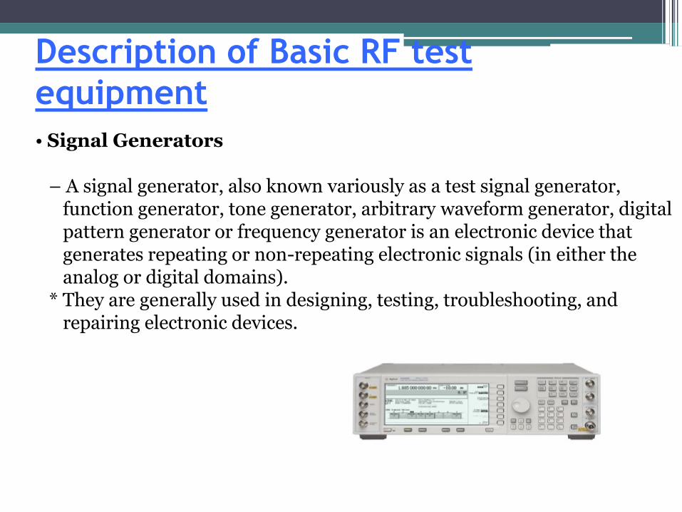
• Signal Generators
– A signal generator, also known variously as a test signal generator, function generator, tone generator, arbitrary waveform generator, digital pattern generator or frequency generator is an electronic device that generates repeating or non-repeating electronic signals (in either the analog or digital domains).
* They are generally used in designing, testing, troubleshooting, and repairing electronic devices.
Description of Basic RF test
equipment• Signal Generators (Continued)
– There are many different types of signal generators, with different purposes and applications (and at varying levels of expense).
– In general, no device is suitable for all possible applications.– Generators as a Continuous Wave (CW) source are often used as local
oscillators in the development or testing of transmitters and receivers.– Used in a swept mode frequency responses of many devices, such as
amplifiers, filters, and mixers can be measured.
Description of Basic RF test
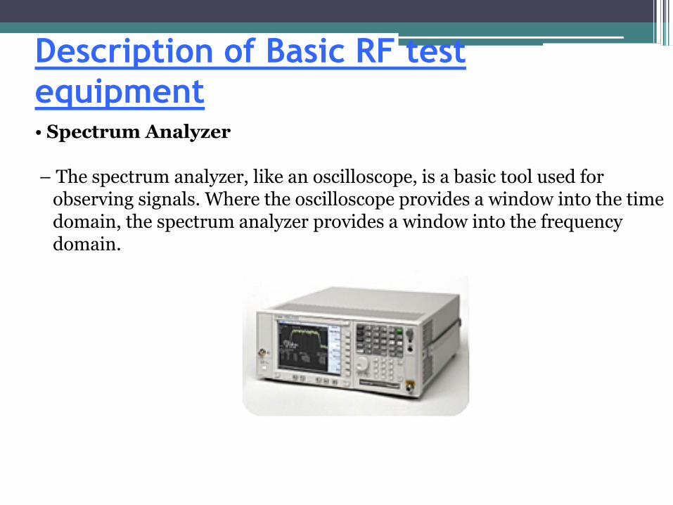
equipment• Spectrum Analyzer
– The spectrum analyzer, like an oscilloscope, is a basic tool used for observing signals. Where the oscilloscope provides a window into the time domain, the spectrum analyzer provides a window into the frequency domain.
Description of Basic RF test
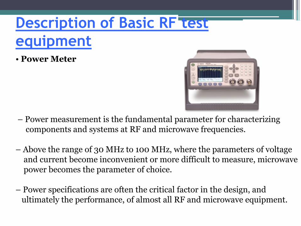
equipment• Power Meter
– Power measurement is the fundamental parameter for characterizing components and systems at RF and microwave frequencies.
– Above the range of 30 MHz to 100 MHz, where the parameters of voltage and current become inconvenient or more difficult to measure, microwave power becomes the parameter of choice.
– Power specifications are often the critical factor in the design, and ultimately the performance, of almost all RF and microwave equipment.
Description of Basic RF test
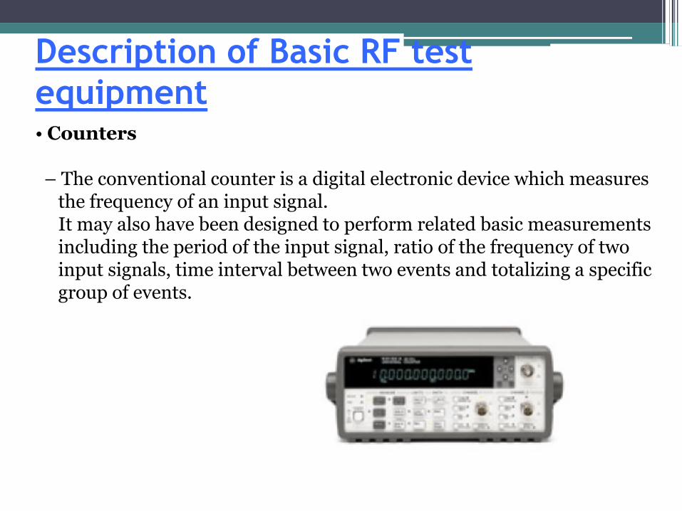
equipment• Counters
– The conventional counter is a digital electronic device which measures the frequency of an input signal. It may also have been designed to perform related basic measurementsincluding the period of the input signal, ratio of the frequency of twoinput signals, time interval between two events and totalizing a specific group of events.

Description of Basic RF test
equipment• Counters
– The conventional counter is a digital electronic device which measures the frequency of an input signal. It may also have been designed to perform related basic measurementsincluding the period of the input signal, ratio of the frequency of twoinput signals, time interval between two events and totalizing a specific group of events.
Recommended