Introduction to Pneumatic Conveying of Solids
Karl JacobThe Dow Chemical Company
Engineering Sciences/Solids ProcessingMidland, [email protected]

Goals for this webinar
Understand various modes of conveying of solids
Learn how to decide on conveying configuration
Examine key aspects of design of conveying systems
Recognize the various conveying system components
Learn how to approach common conveying problems
What is pneumatic conveying?
Pneumatic conveying is the movement of solids
through pipe using gas (usually air) as the motive
force. It differs from hydraulic or slurry conveying in
that the gas expands continuously along the pipe
length. The flow regime in the pipe depends greatly
on the ratio of solids to gas and the particle
characteristics.
Why use pneumatic conveying to move bulk solids?
With the appropriate choice of system, material can be transported with
minimal degradation
Little or no exposure of the product to the environment
Can transport relatively long distances (several thousand feet)
Excellent for multiple sources and multiple destinations
Ability to transport material which might be air, moisture, etc. sensitive
Compared to mechanical conveyors, relative ease in system routing
especially elevation changes
Interfaces well with a variety of transportation modes – truck, railcars,
ships
High reliability of system with comparatively few moving parts
Potential disadvantages
Product degradation as a result of incorrectly
designed system
Pipe/component wear
Not suitable for long distance (beyond a few
thousand feet) conveying – it is difficult to overcome
the gas expansion issue!
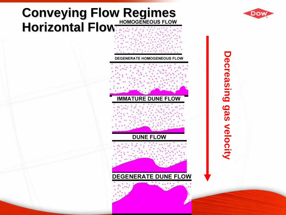
Conveying Flow RegimesHorizontal Flow
Decre
asin
g g
as v
elo
city
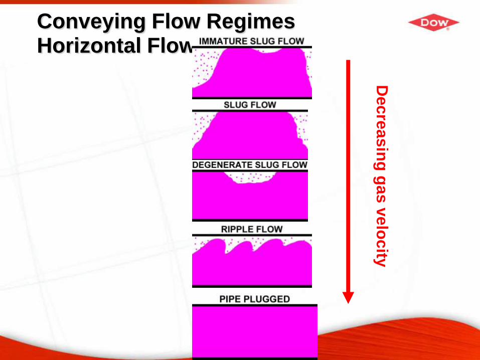
Conveying Flow RegimesHorizontal Flow
Decre
asin
g g
as v
elo
city
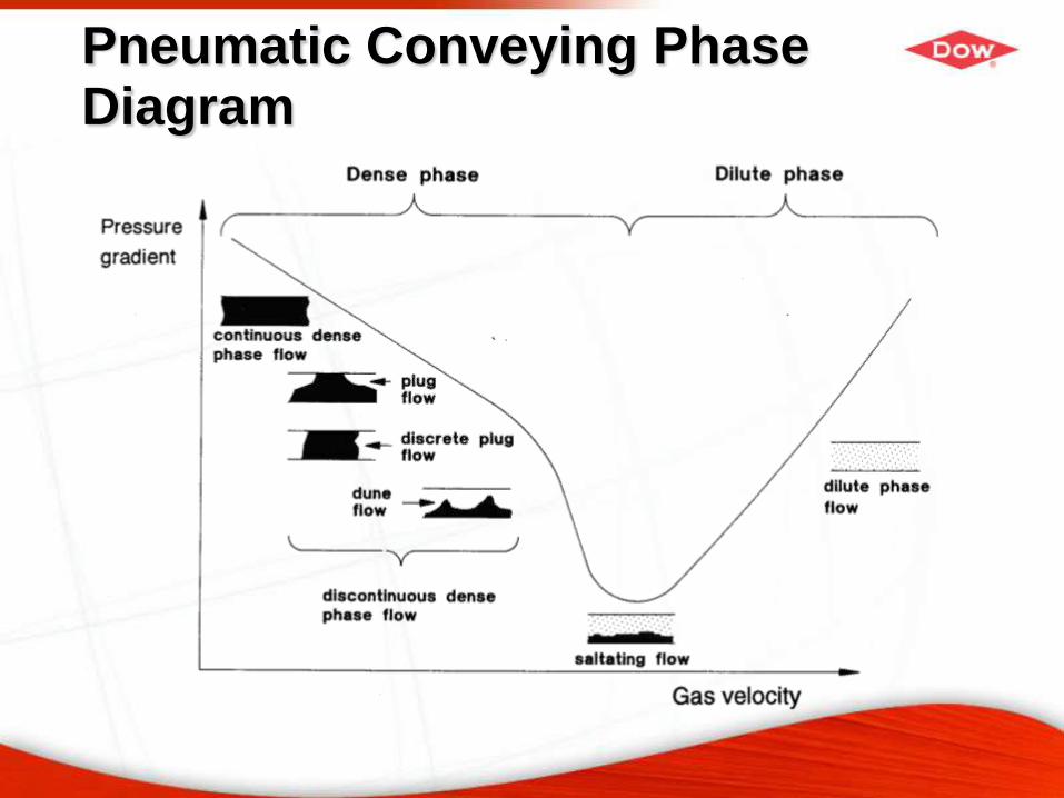
Pneumatic Conveying Phase Diagram
Dense phase vs. dilute
Dense phase
− Low velocity
− Low attrition
− High pressure
− Comparatively high cost
− Small pipe size
− High loadings
Dilute phase
− High velocity
− Can have very high attrition
− Pressure typically < 15 psig
− Low cost
− Larger pipe size
− Low loadings (<10)
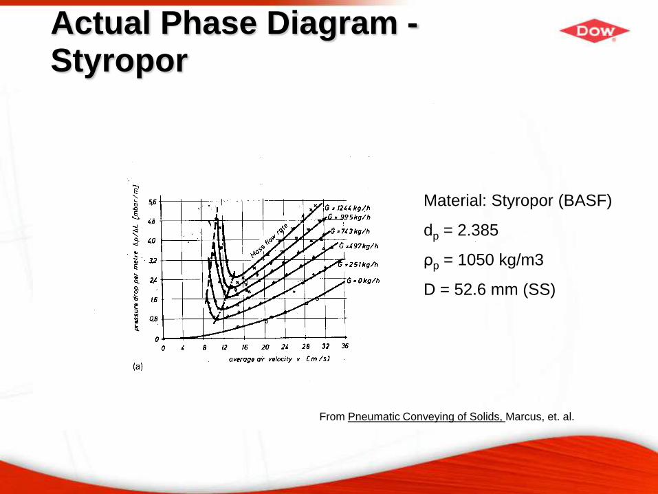
Actual Phase Diagram -Styropor
Material: Styropor (BASF)
dp = 2.385
ρp = 1050 kg/m3
D = 52.6 mm (SS)
From Pneumatic Conveying of Solids, Marcus, et. al.
Basic design issues
Number of sources and destinations? This is
usually determined by plant conditions.
Dense phase vs. dilute phase?
Push vs. pull?
Addressing each of the above
questions will largely dictate the
type of system that needs to be
designed.
Push vs. Pull
Push – generally a pressure system operating above
atmospheric pressure
Pull – a vacuum system operating below atmospheric
pressure - ~ 7 psia is practical lower limit
Choice of push vs. pull depends greatly # of sources and
destinations – some configuration
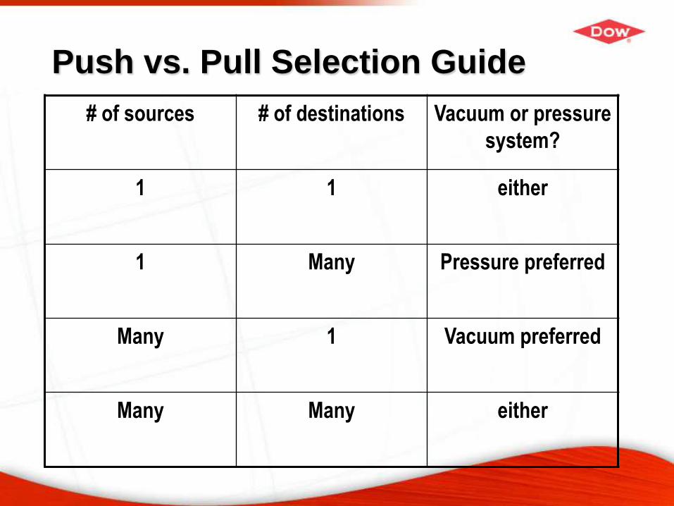
Push vs. Pull Selection Guide
# of sources # of destinations Vacuum or pressure
system?
1 1 either
1 Many Pressure preferred
Many 1 Vacuum preferred
Many Many either
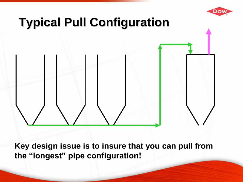
Typical Pull Configuration
Key design issue is to insure that you can pull from
the “longest” pipe configuration!
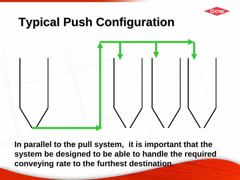
Typical Push Configuration
In parallel to the pull system, it is important that the
system be designed to be able to handle the required
conveying rate to the furthest destination.
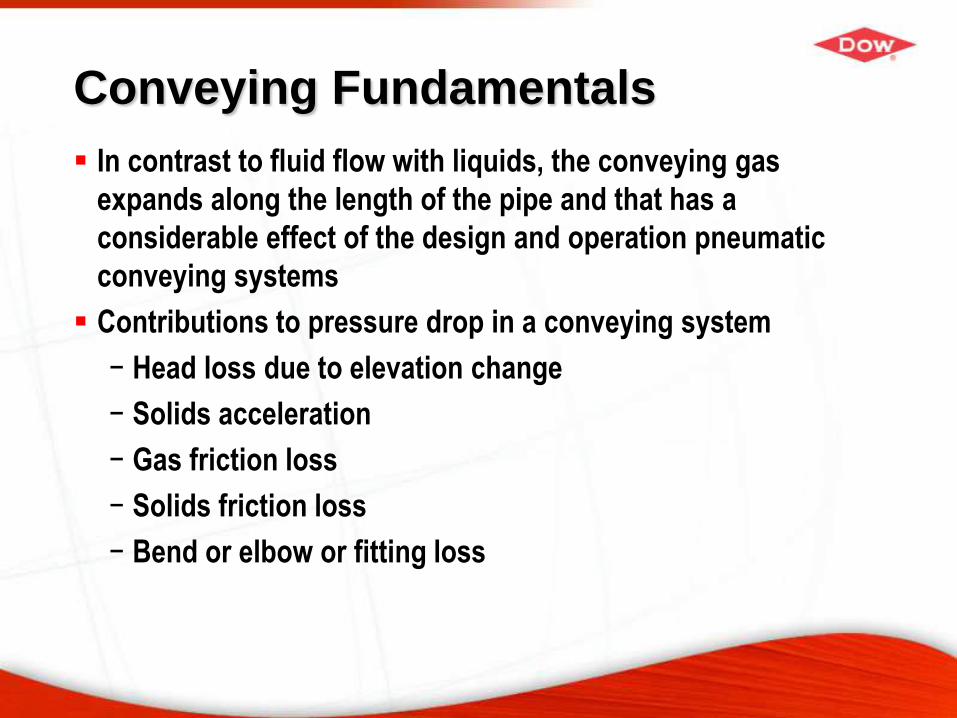
Conveying Fundamentals
In contrast to fluid flow with liquids, the conveying gas
expands along the length of the pipe and that has a
considerable effect of the design and operation pneumatic
conveying systems
Contributions to pressure drop in a conveying system
− Head loss due to elevation change
− Solids acceleration
− Gas friction loss
− Solids friction loss
− Bend or elbow or fitting loss
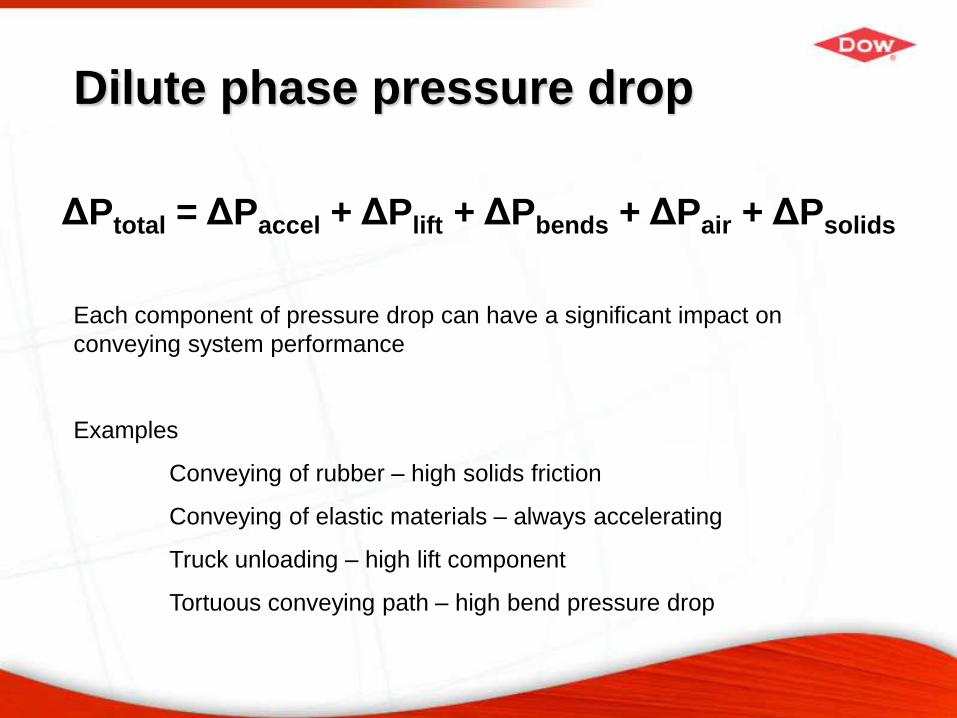
Dilute phase pressure drop
ΔPtotal = ΔPaccel + ΔPlift + ΔPbends + ΔPair + ΔPsolids
Each component of pressure drop can have a significant impact on
conveying system performance
Examples
Conveying of rubber – high solids friction
Conveying of elastic materials – always accelerating
Truck unloading – high lift component
Tortuous conveying path – high bend pressure drop
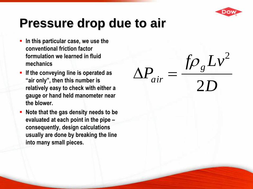
Pressure drop due to air
In this particular case, we use the
conventional friction factor
formulation we learned in fluid
mechanics
If the conveying line is operated as
“air only”, then this number is
relatively easy to check with either a
gauge or hand held manometer near
the blower.
Note that the gas density needs to be
evaluated at each point in the pipe –
consequently, design calculations
usually are done by breaking the line
into many small pieces.
D
LvfP
g
air2
2
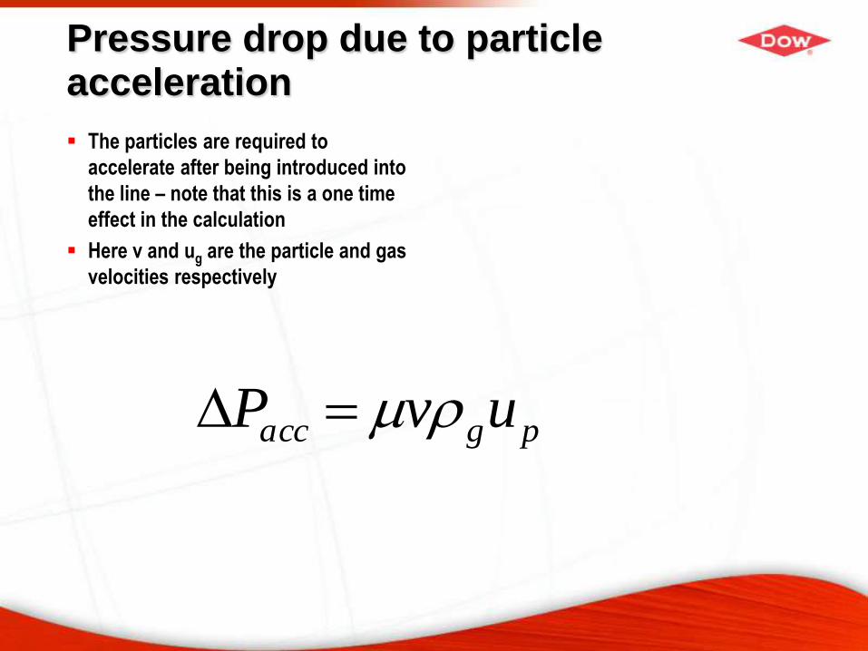
Pressure drop due to particle acceleration
The particles are required to
accelerate after being introduced into
the line – note that this is a one time
effect in the calculation
Here v and ug are the particle and gas
velocities respectively
pgacc uvP
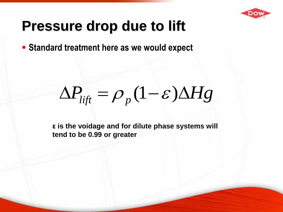
Pressure drop due to lift
Standard treatment here as we would expect
HgP plift )1(
ε is the voidage and for dilute phase systems will
tend to be 0.99 or greater
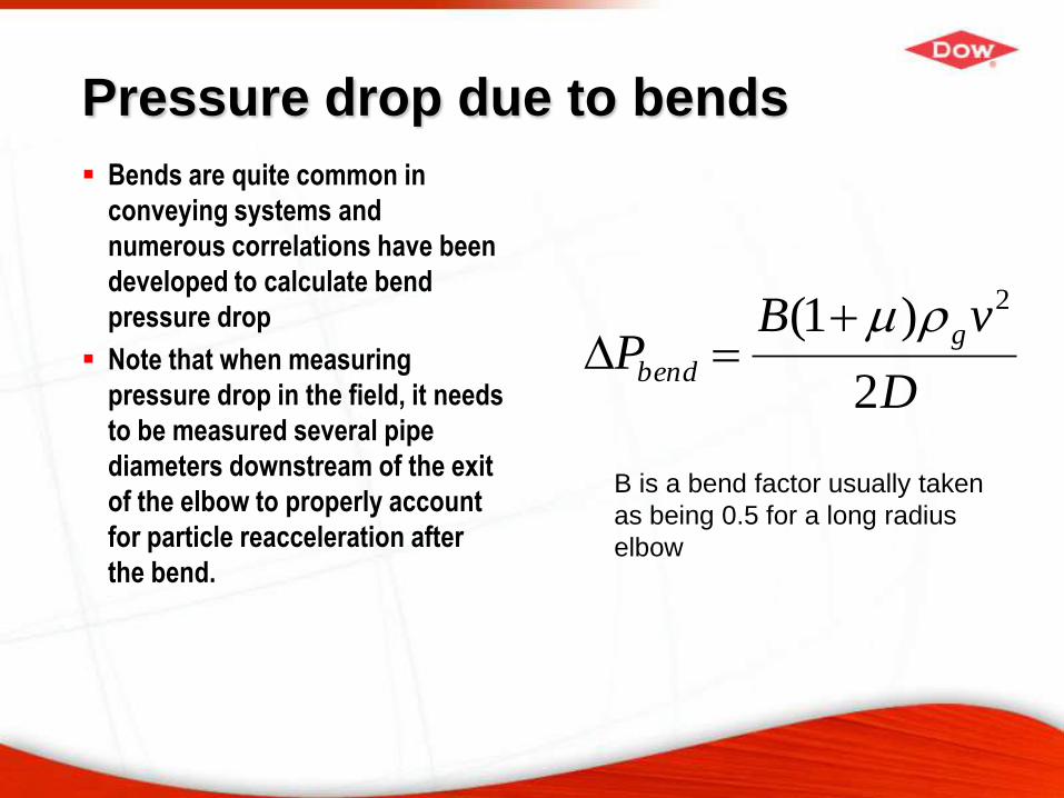
Pressure drop due to bends
Bends are quite common in
conveying systems and
numerous correlations have been
developed to calculate bend
pressure drop
Note that when measuring
pressure drop in the field, it needs
to be measured several pipe
diameters downstream of the exit
of the elbow to properly account
for particle reacceleration after
the bend.
D
vBP
g
bend2
)1( 2
B is a bend factor usually taken
as being 0.5 for a long radius
elbow
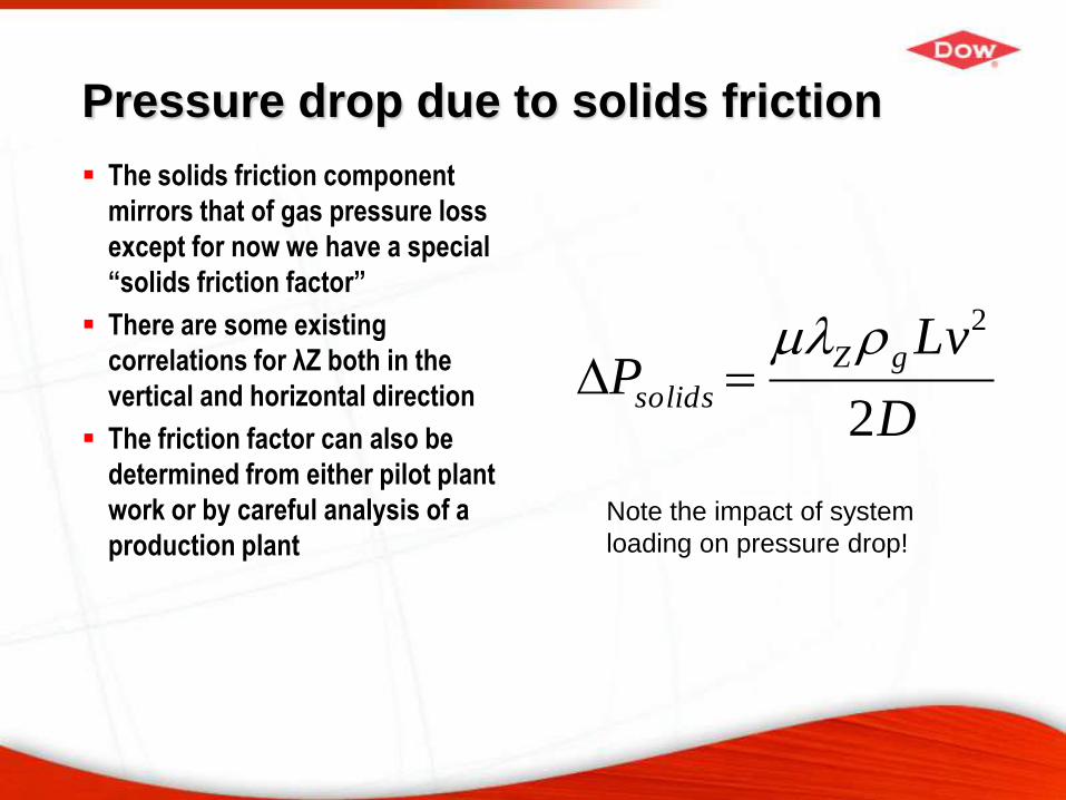
Pressure drop due to solids friction
The solids friction component
mirrors that of gas pressure loss
except for now we have a special
“solids friction factor”
There are some existing
correlations for λZ both in the
vertical and horizontal direction
The friction factor can also be
determined from either pilot plant
work or by careful analysis of a
production plant
D
LvP
gZ
solids2
2
Note the impact of system
loading on pressure drop!
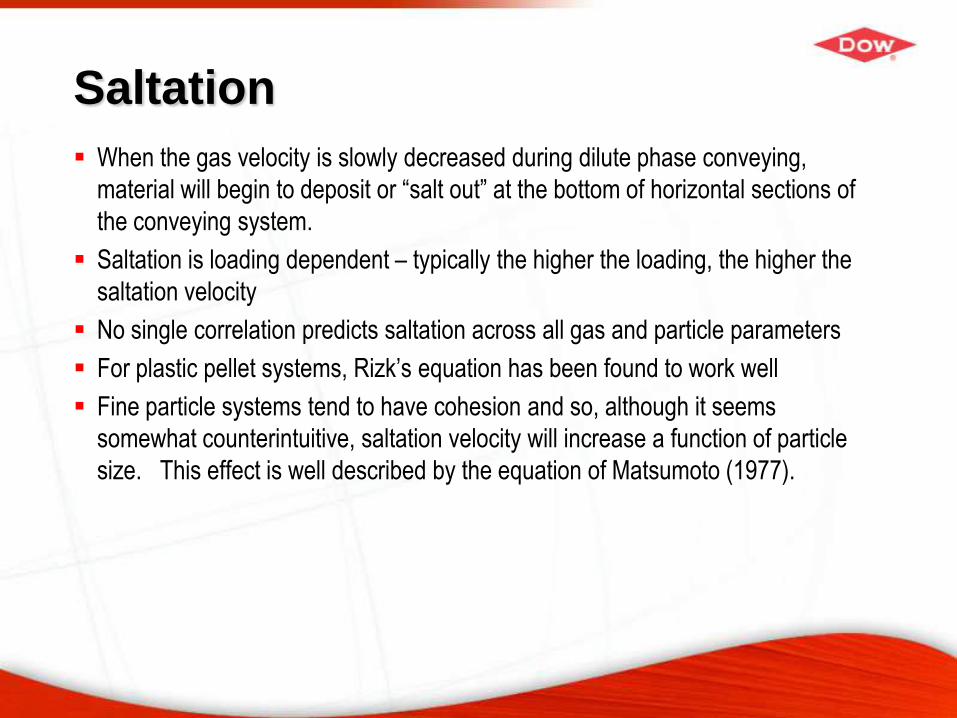
Saltation
When the gas velocity is slowly decreased during dilute phase conveying,
material will begin to deposit or “salt out” at the bottom of horizontal sections of
the conveying system.
Saltation is loading dependent – typically the higher the loading, the higher the
saltation velocity
No single correlation predicts saltation across all gas and particle parameters
For plastic pellet systems, Rizk’s equation has been found to work well
Fine particle systems tend to have cohesion and so, although it seems
somewhat counterintuitive, saltation velocity will increase a function of particle
size. This effect is well described by the equation of Matsumoto (1977).
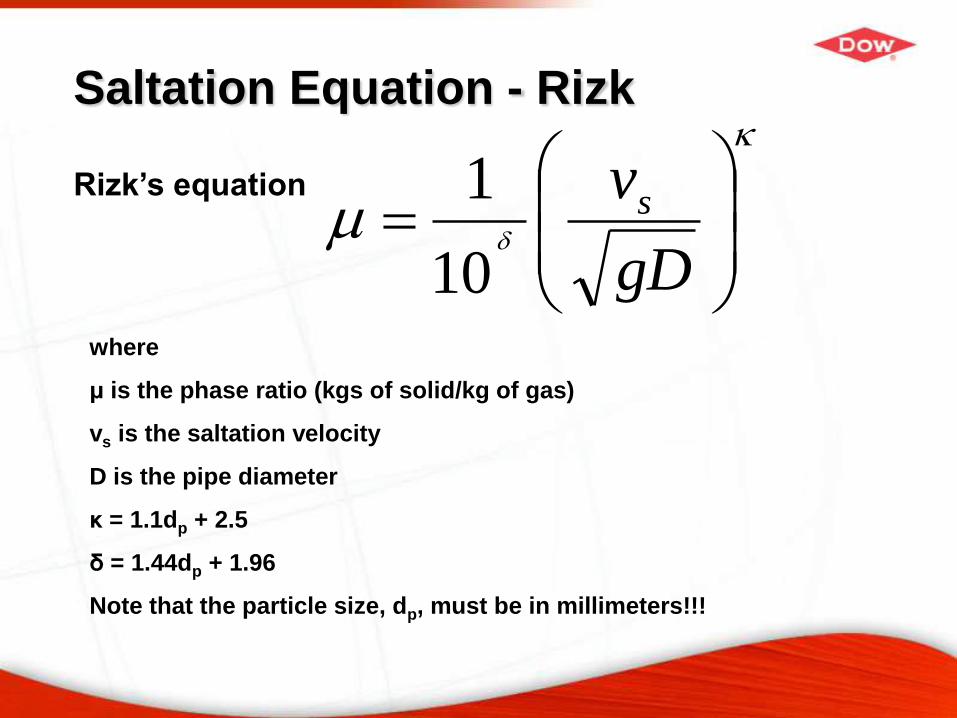
Saltation Equation - Rizk
gD
vs
10
1Rizk’s equation
where
μ is the phase ratio (kgs of solid/kg of gas)
vs is the saltation velocity
D is the pipe diameter
κ = 1.1dp + 2.5
δ = 1.44dp + 1.96
Note that the particle size, dp, must be in millimeters!!!
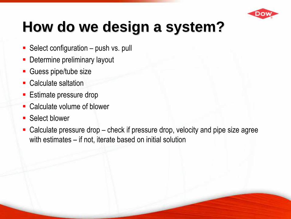
How do we design a system?
Select configuration – push vs. pull
Determine preliminary layout
Guess pipe/tube size
Calculate saltation
Estimate pressure drop
Calculate volume of blower
Select blower
Calculate pressure drop – check if pressure drop, velocity and pipe size agree
with estimates – if not, iterate based on initial solution
Conveying System Components
Air Movers
Feed systems
Pipe/Tube
Dust Collector
Couplings/Flanges
Air Movers
Rotary Lobe Blowers – often called “Roots” blowers
Fans
Compressors
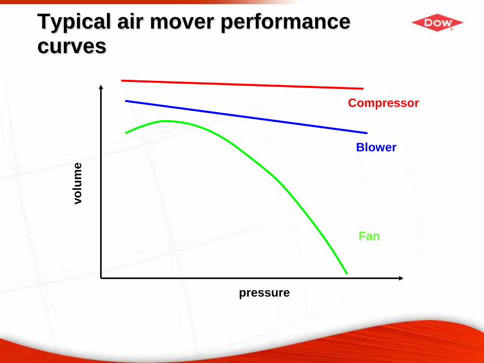
Typical air mover performance curves
pressure
vo
lum
e
Fan
Compressor
Blower
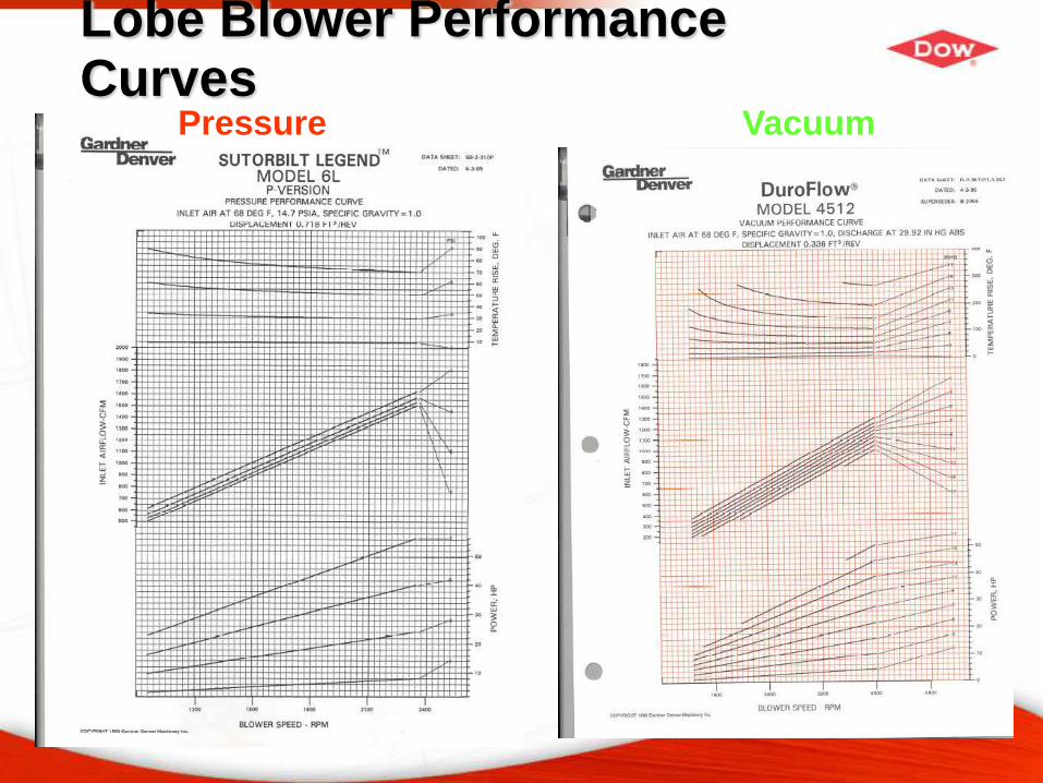
Lobe Blower Performance Curves
Pressure Vacuum
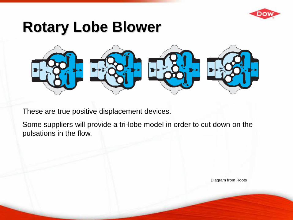
Rotary Lobe Blower
These are true positive displacement devices.
Some suppliers will provide a tri-lobe model in order to cut down on the
pulsations in the flow.
Diagram from Roots
Common feed systems
Rotary valve (also star valve) – the most common feeder used
in conveying systems – considerable versatility – good turn-
up/turn down
Slide valves
Screw feeder
Double flapper valves
Venturis
Pneumatic wands
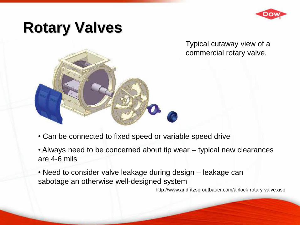
Rotary Valves
http://www.andritzsproutbauer.com/airlock-rotary-valve.asp
Typical cutaway view of a
commercial rotary valve.
• Can be connected to fixed speed or variable speed drive
• Always need to be concerned about tip wear – typical new clearances
are 4-6 mils
• Need to consider valve leakage during design – leakage can
sabotage an otherwise well-designed system
Pipe & Tube
Light gauge (Sch. 10) pipe or tube is routinely used for
conveying systems
Materials of construction include stainless steel, CS and
aluminum
Aluminum is frequently used in the conveying of plastics
Particular attention needs to be given to bends/elbows where
erosive wear can be an issue, even with soft products (e.g.
polymers)
With the wide selection of pipe and tube sizes, it affords the
conveying system designer an excellent opportunity for
optimal system design
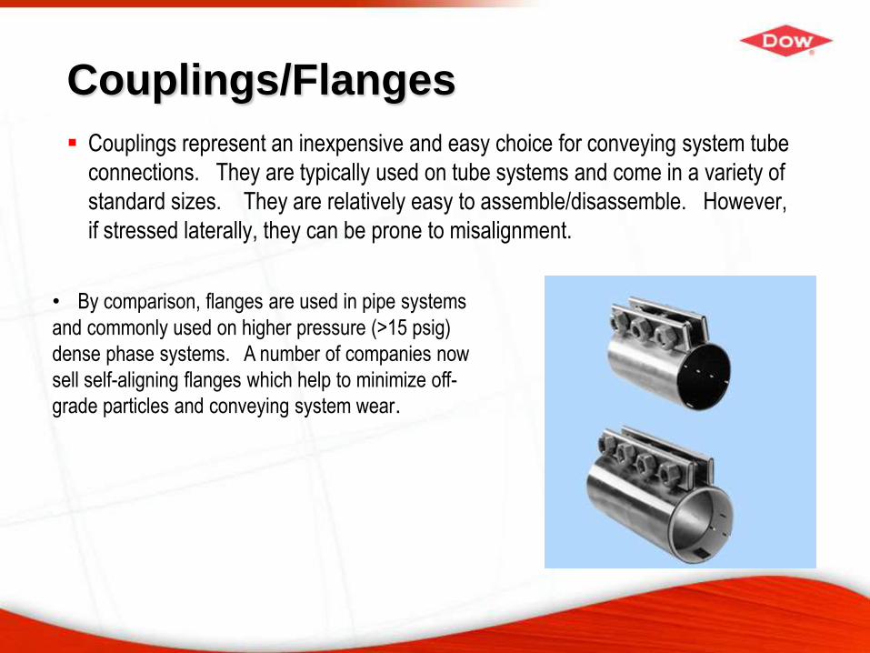
Couplings/Flanges
Couplings represent an inexpensive and easy choice for conveying system tube
connections. They are typically used on tube systems and come in a variety of
standard sizes. They are relatively easy to assemble/disassemble. However,
if stressed laterally, they can be prone to misalignment.
• By comparison, flanges are used in pipe systems
and commonly used on higher pressure (>15 psig)
dense phase systems. A number of companies now
sell self-aligning flanges which help to minimize off-
grade particles and conveying system wear.
Dense phase conveying
Dense phase is recommended when product attrition and
product quality demands our utmost attention
Typically is characterized by low velocity conveying
Conveying mode depends greatly on particle characteristics
Pressures in systems routinely between 1 and 6 barg
A priori prediction of performance extremely difficult
System performance is all about control of plugs of material
Stresses due to large plugs in piping systems can be difficult
to control
Conveying regimes for dense phase pneumatic conveying
Three reasonably distinct conveying modes are observed when conveying
bulk solids in dense phase
− Large materials like plastic pellets will naturally form slugs of material
in the conveying line interspersed between pockets of air
− Medium sized granular materials (example 100-1000 μm) do not make
well formed slugs in the line – the conveying is characterized by the
formation and degradation of degenerate slugs in the line – some type
of air assist is required to maintain slug control. Care must be taken
that too much air isn’t added to the line causing the system to be in
dilute phase
− Fine materials (<50 μm) will naturally form very long slugs in the line,
consequently some sort of plug breaking mechanism must be
installed in order that the pressure drop across the system does not
become inordinately high
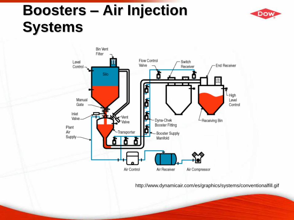
Boosters – Air Injection Systems
http://www.dynamicair.com/es/graphics/systems/conventionalfill.gif
Commonly encountered problems
Increasing conveying system throughput
Attrition/floss formation/pipe erosion
Line failure in dense phase systems
Plugging due to poor layout
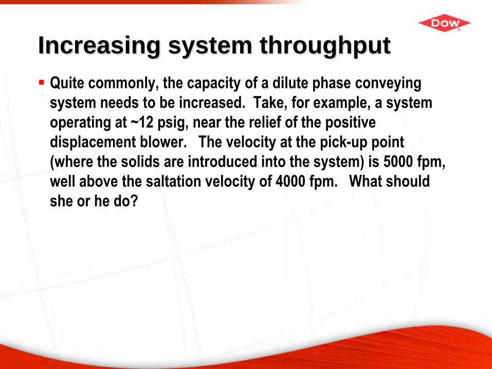
Increasing system throughput
Quite commonly, the capacity of a dilute phase conveying
system needs to be increased. Take, for example, a system
operating at ~12 psig, near the relief of the positive
displacement blower. The velocity at the pick-up point
(where the solids are introduced into the system) is 5000 fpm,
well above the saltation velocity of 4000 fpm. What should
she or he do?
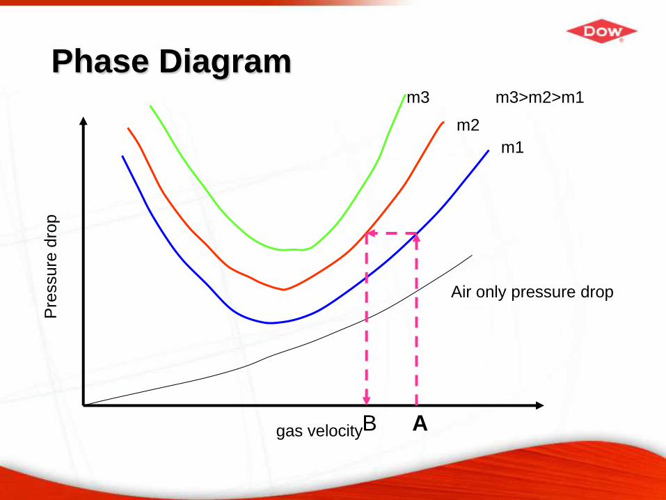
Phase Diagram
gas velocity
Pre
ssure
dro
p
Air only pressure drop
m1
m2
m3 m3>m2>m1
AB
Attrition/Floss formation
Attrition is a key issue in the conveying of solids and can lead to any of the
following issues:
− Poor product performance
− Environmental, Safety and Health issues
− Changes in the flow properties of material
Polymeric materials can be problematic due to the formation of either dust or
floss (also streamers or angel hair)
The key in these situation is velocity control!! Typically attrition is a strong
function of velocity. If the velocity in a dilute phase system can be reduced,
this represents a legitimate option for reduction of attrition.
Attrition α velocity3-5
Line failure in dense phase systems
This can be a very SERIOUS issue.
During the dense phase conveying, it is not unusual to see the line moving or
vibrating as slugs make their way through the conveying line.
Tremendous forces are encountered as a plug switches directions, particularly
around horizontal elbows – example, in large systems it is not uncommon to
see individual plug weights on the order of 500 lbs.
These forces have been and can be very destructive (up to and including
complete line failure)
In this particular case, it is highly recommended to work with a reputable
conveying supplier who understands the issues around this problem
Plugging due to line layout
Often piping designers assume that conveying systems are just like
conventional liquid and gas piping runs, consequently it is not unusual to
have multiple elbows back to back
The particles need some distance to reaccelerate
Even though the system may be designed to be above the saltation
velocity, the particle will simply fall out of suspension and the line will
plug
Two choices to fix this type of problem
− Increase the gas flow – downsides are potential attrition and reduction in
system throughput
− Re-route the line – this is not always the most economical in the short term
but represents the best solution to the problem

Poll Question
We've had three webinars this year on various topics of
solids processing/particle technology (introduction, bins and
hoppers, pneumatic conveying). Our next webinar is
scheduled for January 19, 2011. Which of the following
topics would you most like to hear about next time (please
vote for one)?
Fluidization/fluid bed technology
Gas solid separation (cyclones, dust collectors, bag houses,
wet scrubbers)
Classification of particles (screeners, air classifiers)
Summary
With proper care and thought, pneumatic conveying systems can be designed
and operated to give excellent performance with minimal product degradation
There is considerable SCIENCE behind how these systems work
Thanks for listening!!
Recommended