(989) 358-7000
Be
lt Driv
en L
ive
Ro
ller C
on
ve
yo
rs
- 195 -
ConveyorsConveyorsDrivenLive Roller Conveyors
BeltB
elt D
rive
n L
ive
Ro
ller C
on
ve
yo
rs
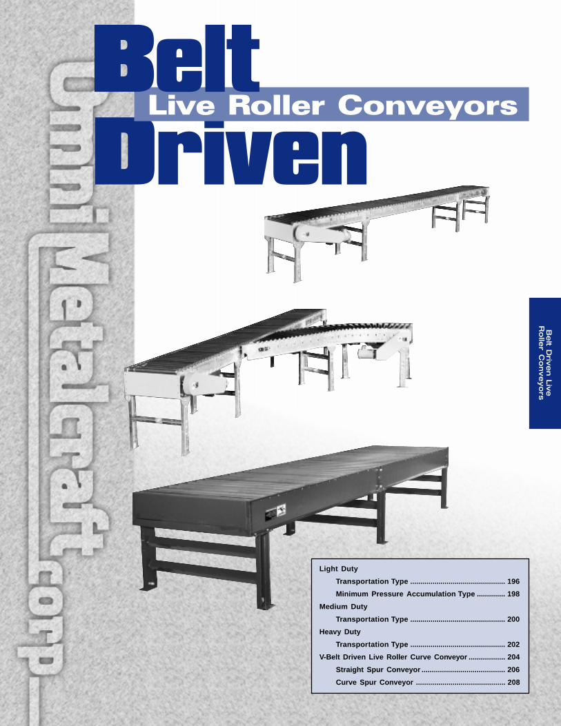
Light Duty
Transportation Type ............................................... 196
Minimum Pressure Accumulation Type .............. 198
Medium Duty
Transportation Type ............................................... 200
Heavy Duty
Transportation Type ............................................... 202
V-Belt Driven Live Roller Curve Conveyor .................. 204
Straight Spur Conveyor ......................................... 206
Curve Spur Conveyor ............................................ 208
(989) 358-7000
Be
lt D
rive
n L
ive
Ro
ller
Co
nve
yo
rs
- 196 -
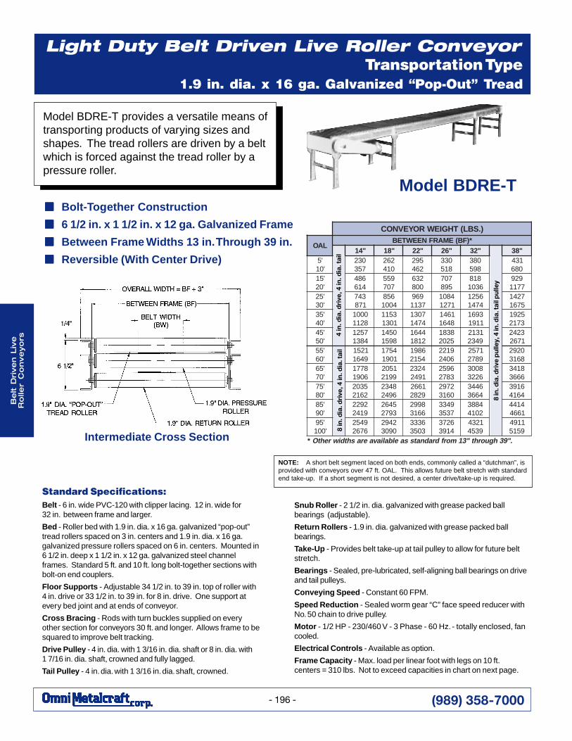
Light Duty Belt Driven Live Roller ConveyorTransportation Type
1.9 in. dia. x 16 ga. Galvanized “Pop-Out” TreadRollers
Standard Specifications:Belt - 6 in. wide PVC-120 with clipper lacing. 12 in. wide for32 in. between frame and larger.
Bed - Roller bed with 1.9 in. dia. x 16 ga. galvanized “pop-out”tread rollers spaced on 3 in. centers and 1.9 in. dia. x 16 ga.galvanized pressure rollers spaced on 6 in. centers. Mounted in6 1/2 in. deep x 1 1/2 in. x 12 ga. galvanized steel channelframes. Standard 5 ft. and 10 ft. long bolt-together sections withbolt-on end couplers.
Floor Supports - Adjustable 34 1/2 in. to 39 in. top of roller with4 in. drive or 33 1/2 in. to 39 in. for 8 in. drive. One support atevery bed joint and at ends of conveyor.
Cross Bracing - Rods with turn buckles supplied on everyother section for conveyors 30 ft. and longer. Allows frame to besquared to improve belt tracking.
Drive Pulley - 4 in. dia. with 1 3/16 in. dia. shaft or 8 in. dia. with1 7/16 in. dia. shaft, crowned and fully lagged.
Tail Pulley - 4 in. dia. with 1 3/16 in. dia. shaft, crowned.
Snub Roller - 2 1/2 in. dia. galvanized with grease packed ballbearings (adjustable).
Return Rollers - 1.9 in. dia. galvanized with grease packed ballbearings.
Take-Up - Provides belt take-up at tail pulley to allow for future beltstretch.
Bearings - Sealed, pre-lubricated, self-aligning ball bearings on driveand tail pulleys.
Conveying Speed - Constant 60 FPM.
Speed Reduction - Sealed worm gear “C” face speed reducer withNo. 50 chain to drive pulley.
Motor - 1/2 HP - 230/460 V - 3 Phase - 60 Hz. - totally enclosed, fancooled.
Electrical Controls - Available as option.
Frame Capacity - Max. load per linear foot with legs on 10 ft.centers = 310 lbs. Not to exceed capacities in chart on next page.
8 in
. dia
. dri
ve p
ulle
y, 4
in. d
ia. t
ail p
ulle
y
8 in
. dia
. dri
ve, 4
in. d
ia. t
ail
4 in
. dia
. dri
ve, 4
in. d
ia. t
ail
NOTE: A short belt segment laced on both ends, commonly called a “dutchman”, isprovided with conveyors over 47 ft. OAL. This allows future belt stretch with standardend take-up. If a short segment is not desired, a center drive/take-up is required.
Model BDRE-T
Model BDRE-T provides a versatile means oftransporting products of varying sizes andshapes. The tread rollers are driven by a beltwhich is forced against the tread roller by apressure roller.
■■■■■ Bolt-Together Construction
■■■■■ 6 1/2 in. x 1 1/2 in. x 12 ga. Galvanized Frame
■■■■■ Between Frame Widths 13 in. Through 39 in.
■■■■■ Reversible (With Center Drive)
Intermediate Cross Section
).SBL(THGIEWROYEVNOC
LAO*)FB(EMARFNEEWTEB
"41 "81 "22 "62 "23 "83'5'01
032753
262014
592264
033815
083895
134086
'51'02
684416
955707
236008
707598
8186301
9297711
'52'03
347178
6584001
9697311
48011721
65214741
72415761
'53'04
00018211
35111031
70314741
16418461
39611191
52913712
'54'05
75214831
05418951
44612181
83815202
13129432
32421762
'55'06
12519461
45711091
68914512
91226042
17529872
02928613
'56'07
87716091
15029912
42321942
69523872
80036223
81436663
'57'08
53022612
84326942
16629282
27920613
64434663
61934614
'58'09
29229142
54623972
89926613
94337353
48832014
41441664
'59'001
94526762
24920903
63333053
62734193
12349354
11949515
* ."93hguorht"31morfdradnatssaelbaliavaerashtdiwrehtO
(989) 358-7000
Be
lt Driv
en L
ive
Ro
ller C
on
ve
yo
rs
- 197 -
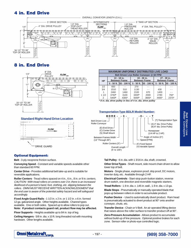
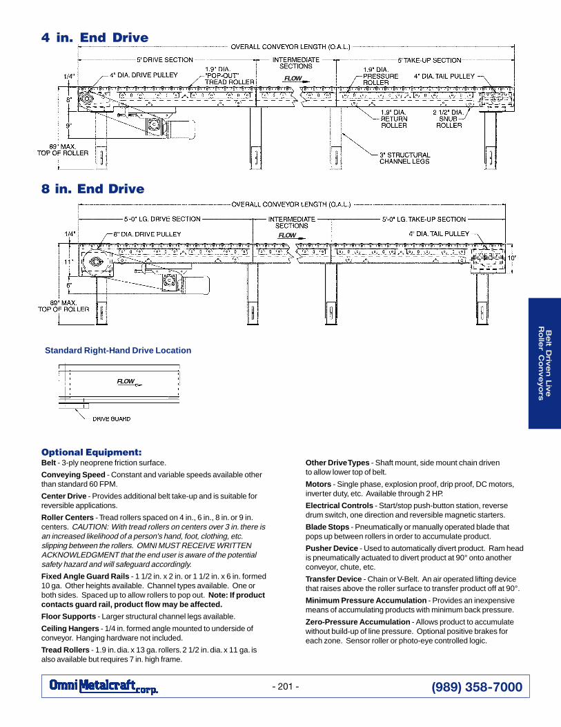
4 in. End Drive
8 in. End Drive
Transpor tation Type BDLR Model Number:
B D R E - - 3 - - 0 - - - T
Optional Equipment:Belt - 3-ply neoprene friction surface.
Conveying Speed - Constant and variable speeds available otherthan standard 60 FPM.
Center Drive - Provides additional belt take-up and is suitable forreversible applications.
Roller Centers - Tread rollers spaced on 4 in., 6 in., 8 in. or 9 in. centers.CAUTION: With tread rollers on centers over 3 in. there is an increasedlikelihood of a person's hand, foot, clothing, etc. slipping between therollers. OMNI MUST RECEIVE WRITTEN ACKNOWLEDGMENT thatthe end user is aware of the potential safety hazard and will safeguardaccordingly.
Fixed Angle Guard Rails - 1 1/2 in. x 2 in. or 1 1/2 in. x 6 in. formed12 ga. galvanized angle. Other heights available. Channel typesavailable. One or both sides. Spaced up to allow rollers to pop out.Note: If product contacts guard rail, product flow may be affected.
Floor Supports - Heights available up to 84 in. top of leg.
Ceiling Hangers - 5/8 in. dia. x 10 ft. long threaded rod with mountinghardware. Other lengths available.
Tail Pulley - 6 in. dia. with 1 3/16 in. dia. shaft, crowned.
Other Drive Types - Shaft mount, side mount chain driven to allowlower top of belt.
Motors - Single phase, explosion proof, drip proof, DC motors,inverter duty, etc. Available through 2 HP.
Electrical Controls - Start-stop push-button station, reversedrum switch, one direction and reversible magnetic starters.
Tread Rollers - 1.9 in. dia. x .145 in. wall., 1.9 in. dia. x 13 ga.
Blade Stops - Pneumatically or manually operated blade thatpops up between rollers in order to accumulate product.
Pusher Device - Used to automatically divert product. Ram headis pneumatically actuated to divert product at 90° onto anotherconveyor, chute, etc.
Transfer Device - Chain or V-Belt. An air operated lifting devicethat raises above the roller surface to transfer product off at 90°.
Zero-Pressure Accumulation - Allows product to accumulatewithout build-up of line pressure. Optional positive brakes for eachzone. Sensor roller or photo-eye controlled logic.
_____ _ __ _ __ _ _ _ _ _ __
Belt Driven LiveRoller Conveyor
Between Frames Width(13" Through 39")
Roller Centers (3")
Overall Length(5' to 100')
(F) Fixed Speed(V) Variable Speed
Speed (FPM)
(T) Transportation Type
Angle of Incline (0°)
(E) End Drive(C) Center Drive(S) Shaft Mount
Horsepower(1/4 HP to 2 HP)
(4) 4" dia. Drive Pulley(8) 8" dia. Drive Pulley
Standard Right-Hand Drive Location
DAOLEVILDETUBIRTSIDYLMROFINUMUMIXAMMPF06@royevnoCrelloReviLnevirDtleB
PH.ni81-31
emarFneewteB.ni62-91
emarFneewteB.ni93-72
emarFneewteB.tf05-5 .tf001-55 .tf05-5 .tf001-55 .tf05-5 .tf001-55
2/14/3
12/11
2
056015106420673 *0045 *
--01506410013*0034
072031100120043 *0005 *
----0760002*0063
--03400410872*0044
------*057*0732
yellupevird.aid.ni4foueilniyellupevird.aid.ni8*
DRIVE GUARD
FLOW
FLOW
FLOW
(989) 358-7000
Be
lt D
rive
n L
ive
Ro
ller
Co
nve
yo
rs
- 198 -
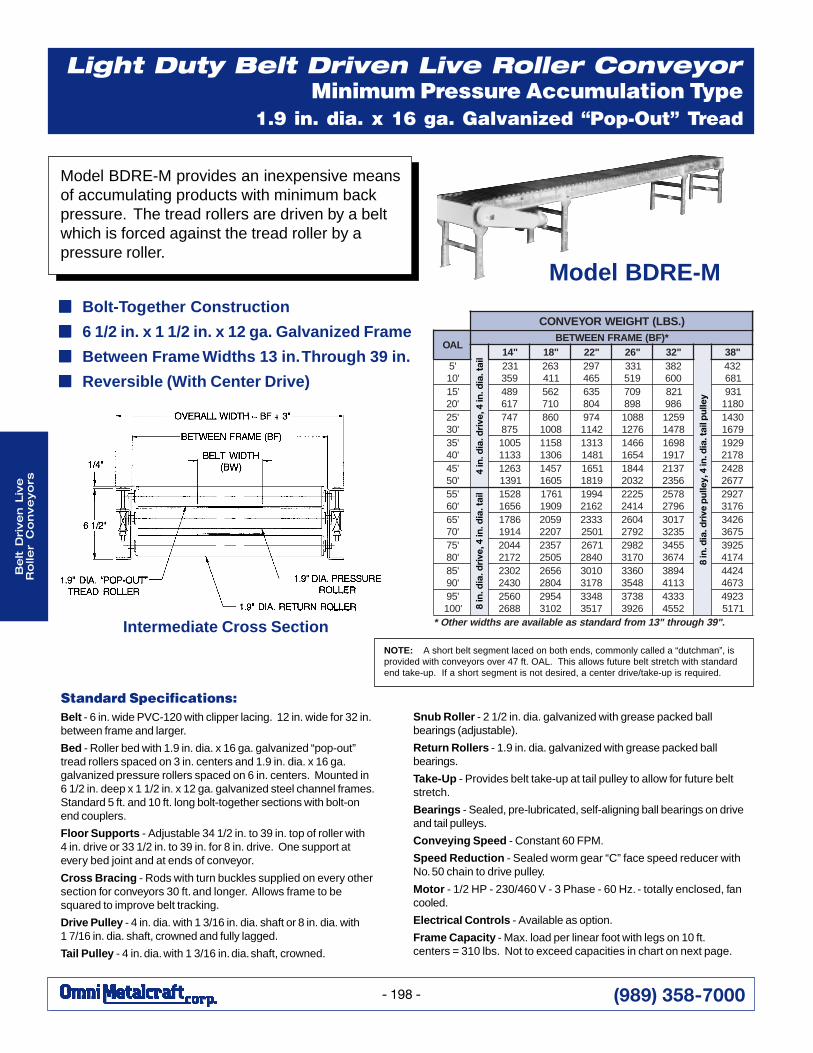
Light Duty Belt Driven Live Roller ConveyorMinimum Pressure Accumulation Type
1.9 in. dia. x 16 ga. Galvanized “Pop-Out” TreadRollers
Snub Roller - 2 1/2 in. dia. galvanized with grease packed ballbearings (adjustable).
Return Rollers - 1.9 in. dia. galvanized with grease packed ballbearings.
Take-Up - Provides belt take-up at tail pulley to allow for future beltstretch.
Bearings - Sealed, pre-lubricated, self-aligning ball bearings on driveand tail pulleys.
Conveying Speed - Constant 60 FPM.
Speed Reduction - Sealed worm gear “C” face speed reducer withNo. 50 chain to drive pulley.
Motor - 1/2 HP - 230/460 V - 3 Phase - 60 Hz. - totally enclosed, fancooled.
Electrical Controls - Available as option.
Frame Capacity - Max. load per linear foot with legs on 10 ft.centers = 310 lbs. Not to exceed capacities in chart on next page.
Standard Specifications:Belt - 6 in. wide PVC-120 with clipper lacing. 12 in. wide for 32 in.between frame and larger.
Bed - Roller bed with 1.9 in. dia. x 16 ga. galvanized “pop-out”tread rollers spaced on 3 in. centers and 1.9 in. dia. x 16 ga.galvanized pressure rollers spaced on 6 in. centers. Mounted in6 1/2 in. deep x 1 1/2 in. x 12 ga. galvanized steel channel frames.Standard 5 ft. and 10 ft. long bolt-together sections with bolt-onend couplers.
Floor Supports - Adjustable 34 1/2 in. to 39 in. top of roller with4 in. drive or 33 1/2 in. to 39 in. for 8 in. drive. One support atevery bed joint and at ends of conveyor.
Cross Bracing - Rods with turn buckles supplied on every othersection for conveyors 30 ft. and longer. Allows frame to besquared to improve belt tracking.
Drive Pulley - 4 in. dia. with 1 3/16 in. dia. shaft or 8 in. dia. with1 7/16 in. dia. shaft, crowned and fully lagged.
Tail Pulley - 4 in. dia. with 1 3/16 in. dia. shaft, crowned.
8 in
. dia
. dri
ve p
ulle
y, 4
in. d
ia. t
ail p
ulle
y
8 in
. dia
. dri
ve, 4
in. d
ia. t
ail
4 in
. dia
. dri
ve, 4
in. d
ia. t
ail
Model BDRE-M provides an inexpensive meansof accumulating products with minimum backpressure. The tread rollers are driven by a beltwhich is forced against the tread roller by apressure roller.
■■■■■ Bolt-Together Construction
■■■■■ 6 1/2 in. x 1 1/2 in. x 12 ga. Galvanized Frame
■■■■■ Between Frame Widths 13 in. Through 39 in.
■■■■■ Reversible (With Center Drive)
Intermediate Cross SectionNOTE: A short belt segment laced on both ends, commonly called a “dutchman”, isprovided with conveyors over 47 ft. OAL. This allows future belt stretch with standardend take-up. If a short segment is not desired, a center drive/take-up is required.
Model BDRE-M
).SBL(THGIEWROYEVNOC
LAO*)FB(EMARFNEEWTEB
"41 "81 "22 "62 "23 "83'5'01
132953
362114
792564
133915
283006
234186
'51'02
984716
265017
536408
907898
128689
1390811
'52'03
747578
0688001
4792411
88016721
95218741
03419761
'53'04
50013311
85116031
31311841
66414561
89617191
92918712
'54'05
36211931
75415061
15619181
44812302
73126532
82427762
'55'06
82516561
16719091
49912612
52224142
87526972
72926713
'56'07
68714191
95027022
33321052
40622972
71035323
62435763
'57'08
44022712
75325052
17620482
28920713
55434763
52934714
'58'09
20320342
65624082
01038713
06338453
49833114
42443764
'59'001
06528862
45922013
84337153
83736293
33342554
32941715
."93hguorht"31morfdradnatssaelbaliavaerashtdiwrehtO*
(989) 358-7000
Be
lt Driv
en L
ive
Ro
ller C
on
ve
yo
rs
- 199 -
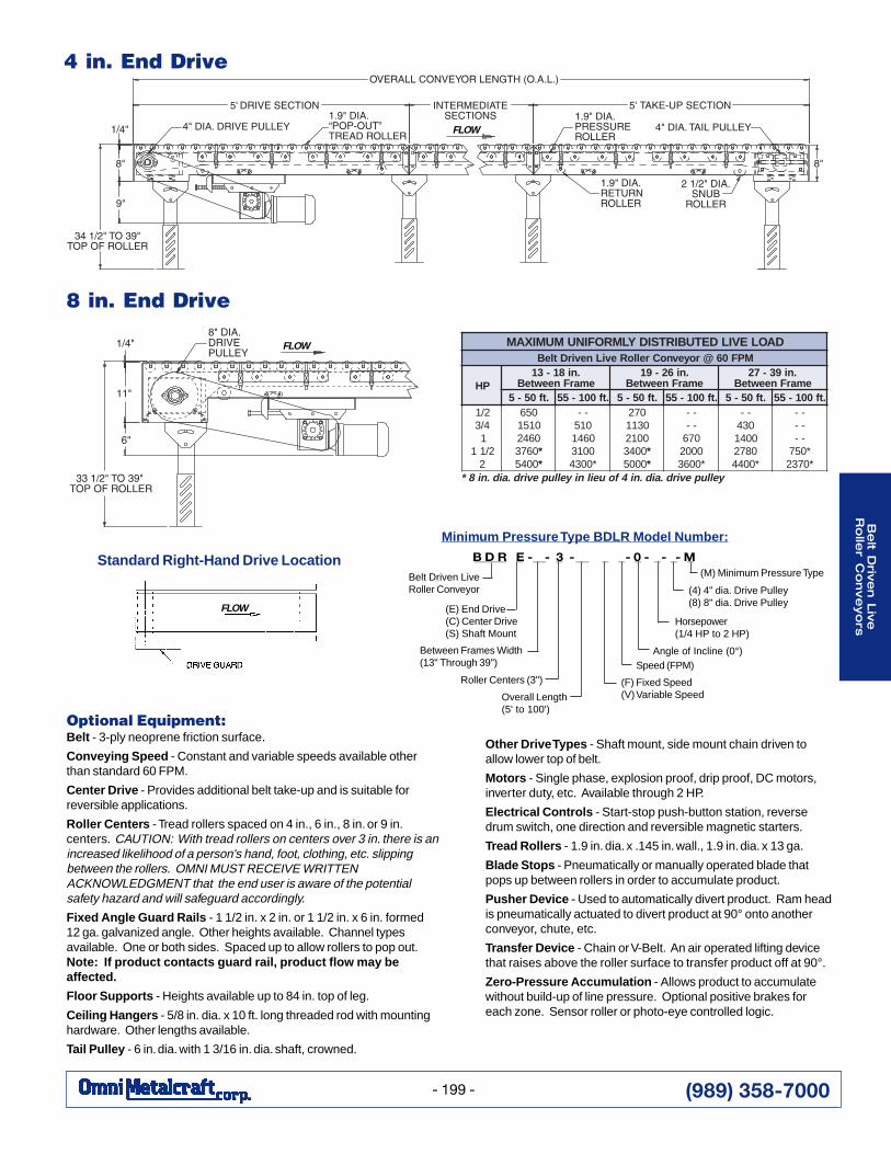
4 in. End Drive
8 in. End Drive
Minim um Pressure Type BDLR Model Number:
B D R E - - 3 - - 0 - - - M
Optional Equipment:Belt - 3-ply neoprene friction surface.
Conveying Speed - Constant and variable speeds available otherthan standard 60 FPM.
Center Drive - Provides additional belt take-up and is suitable forreversible applications.
Roller Centers - Tread rollers spaced on 4 in., 6 in., 8 in. or 9 in.centers. CAUTION: With tread rollers on centers over 3 in. there is anincreased likelihood of a person's hand, foot, clothing, etc. slippingbetween the rollers. OMNI MUST RECEIVE WRITTENACKNOWLEDGMENT that the end user is aware of the potentialsafety hazard and will safeguard accordingly.
Fixed Angle Guard Rails - 1 1/2 in. x 2 in. or 1 1/2 in. x 6 in. formed12 ga. galvanized angle. Other heights available. Channel typesavailable. One or both sides. Spaced up to allow rollers to pop out.Note: If product contacts guard rail, product flow may beaffected.
Floor Supports - Heights available up to 84 in. top of leg.
Ceiling Hangers - 5/8 in. dia. x 10 ft. long threaded rod with mountinghardware. Other lengths available.
Tail Pulley - 6 in. dia. with 1 3/16 in. dia. shaft, crowned.
Other Drive Types - Shaft mount, side mount chain driven toallow lower top of belt.
Motors - Single phase, explosion proof, drip proof, DC motors,inverter duty, etc. Available through 2 HP.
Electrical Controls - Start-stop push-button station, reversedrum switch, one direction and reversible magnetic starters.
Tread Rollers - 1.9 in. dia. x .145 in. wall., 1.9 in. dia. x 13 ga.
Blade Stops - Pneumatically or manually operated blade thatpops up between rollers in order to accumulate product.
Pusher Device - Used to automatically divert product. Ram headis pneumatically actuated to divert product at 90° onto anotherconveyor, chute, etc.
Transfer Device - Chain or V-Belt. An air operated lifting devicethat raises above the roller surface to transfer product off at 90°.
Zero-Pressure Accumulation - Allows product to accumulatewithout build-up of line pressure. Optional positive brakes foreach zone. Sensor roller or photo-eye controlled logic.
_____ _ __ _ __ _ _ _ _ _ _
Belt Driven LiveRoller Conveyor
Between Frames Width(13" Through 39")
Roller Centers (3")
Overall Length(5' to 100')
(F) Fixed Speed(V) Variable Speed
Speed (FPM)Angle of Incline (0°)
(E) End Drive(C) Center Drive(S) Shaft Mount
Horsepower(1/4 HP to 2 HP)
(4) 4" dia. Drive Pulley(8) 8" dia. Drive Pulley
(M) Minimum Pressure TypeStandard Right-Hand Drive Location
DAOLEVILDETUBIRTSIDYLMROFINUMUMIXAMMPF06@royevnoCrelloReviLnevirDtleB
PH.ni81-31
emarFneewteB.ni62-91
emarFneewteB.ni93-72
emarFneewteB.tf05-5 .tf001-55 .tf05-5 .tf001-55 .tf05-5 .tf001-55
2/14/3
12/11
2
056015106420673 *0045 *
--01506410013*0034
072031100120043 *0005 *
----0760002*0063
--03400410872*0044
------*057*0732
yellupevird.aid.ni4foueilniyellupevird.aid.ni8*
FLOW
FLOW
FLOW
(989) 358-7000
Be
lt D
rive
n L
ive
Ro
ller
Co
nve
yo
rs
- 200 -
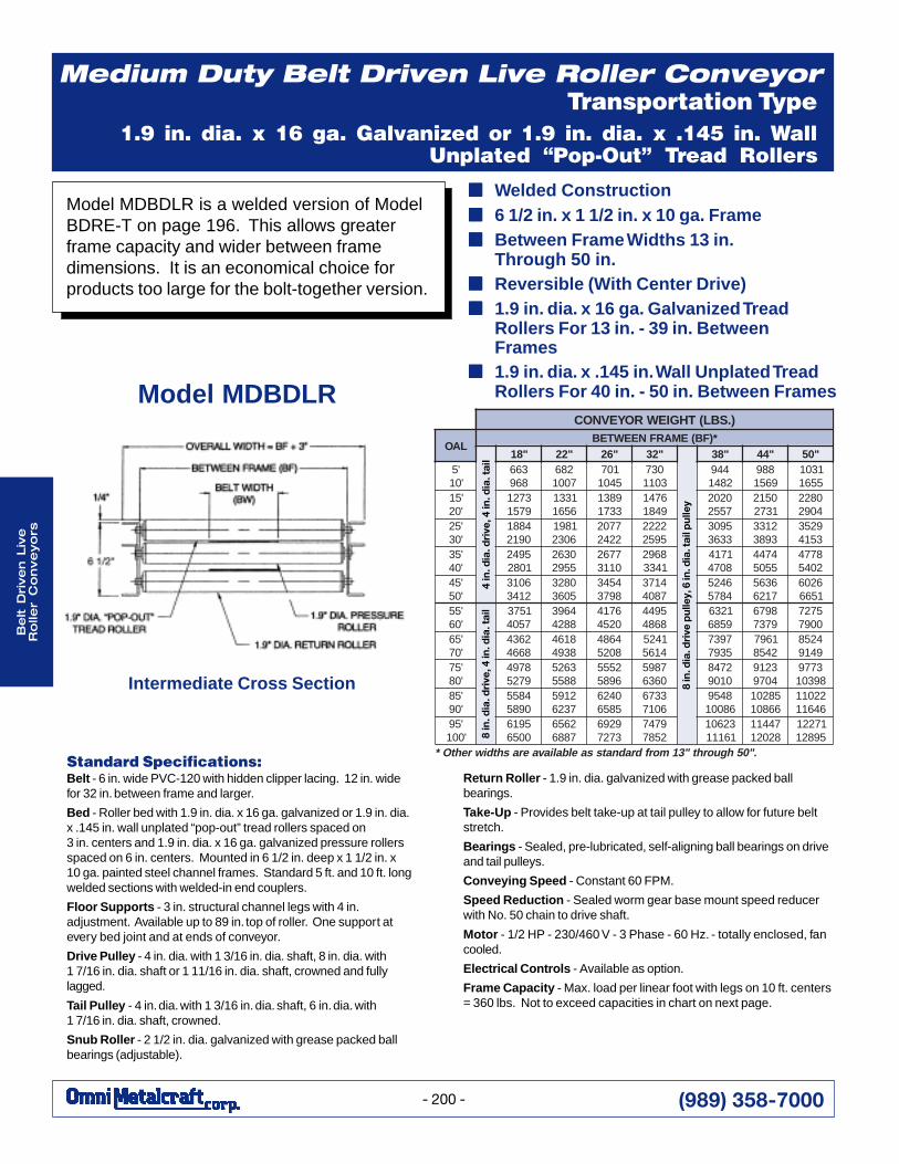
Medium Duty Belt Driven Live Roller ConveyorTransportation Type
1.9 in. dia. x 16 ga. Galvanized or 1.9 in. dia. x .145 in. WallUnplated “Pop-Out” Tread Rollers
Return Roller - 1.9 in. dia. galvanized with grease packed ballbearings.
Take-Up - Provides belt take-up at tail pulley to allow for future beltstretch.
Bearings - Sealed, pre-lubricated, self-aligning ball bearings on driveand tail pulleys.
Conveying Speed - Constant 60 FPM.
Speed Reduction - Sealed worm gear base mount speed reducerwith No. 50 chain to drive shaft.
Motor - 1/2 HP - 230/460 V - 3 Phase - 60 Hz. - totally enclosed, fancooled.
Electrical Controls - Available as option.
Frame Capacity - Max. load per linear foot with legs on 10 ft. centers= 360 lbs. Not to exceed capacities in chart on next page.
Standard Specifications:Belt - 6 in. wide PVC-120 with hidden clipper lacing. 12 in. widefor 32 in. between frame and larger.
Bed - Roller bed with 1.9 in. dia. x 16 ga. galvanized or 1.9 in. dia.x .145 in. wall unplated “pop-out” tread rollers spaced on3 in. centers and 1.9 in. dia. x 16 ga. galvanized pressure rollersspaced on 6 in. centers. Mounted in 6 1/2 in. deep x 1 1/2 in. x10 ga. painted steel channel frames. Standard 5 ft. and 10 ft. longwelded sections with welded-in end couplers.
Floor Supports - 3 in. structural channel legs with 4 in.adjustment. Available up to 89 in. top of roller. One support atevery bed joint and at ends of conveyor.
Drive Pulley - 4 in. dia. with 1 3/16 in. dia. shaft, 8 in. dia. with1 7/16 in. dia. shaft or 1 11/16 in. dia. shaft, crowned and fullylagged.
Tail Pulley - 4 in. dia. with 1 3/16 in. dia. shaft, 6 in. dia. with1 7/16 in. dia. shaft, crowned.
Snub Roller - 2 1/2 in. dia. galvanized with grease packed ballbearings (adjustable).
8 in
. dia
. dri
ve p
ulle
y, 6
in. d
ia. t
ail p
ulle
y
8 in
. dia
. dri
ve, 4
in. d
ia. t
ail
4 in
. dia
. dri
ve, 4
in. d
ia. t
ail
Intermediate Cross Section
■■■■■ Welded Construction■■■■■ 6 1/2 in. x 1 1/2 in. x 10 ga. Frame■■■■■ Between Frame Widths 13 in.
Through 50 in.■■■■■ Reversible (With Center Drive)■■■■■ 1.9 in. dia. x 16 ga. Galvanized Tread
Rollers For 13 in. - 39 in. BetweenFrames
■■■■■ 1.9 in. dia. x .145 in. Wall Unplated TreadRollers For 40 in. - 50 in. Between FramesModel MDBDLR
).SBL(THGIEWROYEVNOC
LAO*)FB(EMARFNEEWTEB
"81 "22 "62 "23 "83 "44 "05'5'01
366869
2867001
1075401
0373011
4492841
8899651
13015561
'51'02
37219751
13316561
98313371
67419481
02027552
05121372
08224092
'52'03
48810912
18916032
77022242
22225952
59033363
21333983
92533514
'53'04
59421082
03625592
77620113
86921433
17148074
47445505
87742045
'54'05
60132143
08235063
45438973
41737804
64254875
63657126
62061566
'55'06
15737504
46938824
67140254
59448684
12369586
89769737
57270097
'56'07
26348664
81648394
46848025
14254165
79375397
16972458
42589419
'57'08
87949725
36258855
25556985
78950636
27480109
32194079
377989301
'58'09
48550985
21957326
04265856
33766017
845968001
5820166801
2201164611
'59'001
59160056
26567886
92963727
97472587
3260116111
7441182021
1722159821
."05hguorht"31morfdradnatssaelbaliavaerashtdiwrehtO*
6 1/2"
Model MDBDLR is a welded version of ModelBDRE-T on page 196. This allows greaterframe capacity and wider between framedimensions. It is an economical choice forproducts too large for the bolt-together version.
(989) 358-7000
Be
lt Driv
en L
ive
Ro
ller C
on
ve
yo
rs
- 201 -
Optional Equipment:Belt - 3-ply neoprene friction surface.
Conveying Speed - Constant and variable speeds available otherthan standard 60 FPM.
Center Drive - Provides additional belt take-up and is suitable forreversible applications.
Roller Centers - Tread rollers spaced on 4 in., 6 in., 8 in. or 9 in.centers. CAUTION: With tread rollers on centers over 3 in. there isan increased likelihood of a person's hand, foot, clothing, etc.slipping between the rollers. OMNI MUST RECEIVE WRITTENACKNOWLEDGMENT that the end user is aware of the potentialsafety hazard and will safeguard accordingly.
Fixed Angle Guard Rails - 1 1/2 in. x 2 in. or 1 1/2 in. x 6 in. formed10 ga. Other heights available. Channel types available. One orboth sides. Spaced up to allow rollers to pop out. Note: If productcontacts guard rail, product flow may be affected.
Floor Supports - Larger structural channel legs available.
Ceiling Hangers - 1/4 in. formed angle mounted to underside ofconveyor. Hanging hardware not included.
Tread Rollers - 1.9 in. dia. x 13 ga. rollers. 2 1/2 in. dia. x 11 ga. isalso available but requires 7 in. high frame.
Other Drive Types - Shaft mount, side mount chain drivento allow lower top of belt.
Motors - Single phase, explosion proof, drip proof, DC motors,inverter duty, etc. Available through 2 HP.
Electrical Controls - Start/stop push-button station, reversedrum switch, one direction and reversible magnetic starters.
Blade Stops - Pneumatically or manually operated blade thatpops up between rollers in order to accumulate product.
Pusher Device - Used to automatically divert product. Ram headis pneumatically actuated to divert product at 90° onto anotherconveyor, chute, etc.
Transfer Device - Chain or V-Belt. An air operated lifting devicethat raises above the roller surface to transfer product off at 90°.
Minimum Pressure Accumulation - Provides an inexpensivemeans of accumulating products with minimum back pressure.
Zero-Pressure Accumulation - Allows product to accumulatewithout build-up of line pressure. Optional positive brakes foreach zone. Sensor roller or photo-eye controlled logic.
4 in. End Drive
8 in. End Drive
Standard Right-Hand Drive Location
FLOW
FLOW
FLOW
(989) 358-7000
Be
lt D
rive
n L
ive
Ro
ller
Co
nve
yo
rs
- 202 -
Belt Driven Live Roller ConveyorMinimum Pressure Accumulation Type
Model BDRE-T
Floor Supports - 4 in. structural channel legs with 4 in. adjustment.Available up to 89 in. top of roller. One support at every bed joint andat ends of conveyor.
Take-Up - Provides belt take-up at tail pulley to allow for future beltstretch.
Bearings - Sealed, pre-lubricated, self-aligning ball bearings on driveand tail pulleys.
Conveying Speed - Constant 30 FPM.
Motor - 1 HP - 230/460 V - 3 Phase - 60 Hz. - totally enclosed, fancooled.
Electrical Controls - Available as option.
Frame Capacity - Max. load per linear foot with legs on 10 ft. centers= 1280 lbs. Not to exceed capacities in chart on next page.
Standard Specifications:Belt - PVC-120 with hidden clipper lacing BF dependent.
Bed - Roller bed with 2 1/2 in. dia. x 11 ga. “pop-out” treadrollers spaced on 3 in. centers and 1.9 in. dia. x 16 ga.galvanized pressure rollers spaced on 6 in. centers. Mounted in11 3/4 in. deep x 1 1/2 in. x 7 ga. painted steel channel frames.Standard 5 ft. and 10 ft. long welded sections with welded-in endcouplers.
Drive Pulley - 8 in. dia. with 1 7/16 in. dia. shaft, crowned andfully lagged.
Tail Pulley - 4 in. dia. with 1 3/16 in. dia. shaft, crowned.
Snub Roller - 2 1/2 in. dia. with grease packed ball bearings(adjustable).
Return Rollers - 1.9 in. dia. galvanized with grease packed ballbearings.
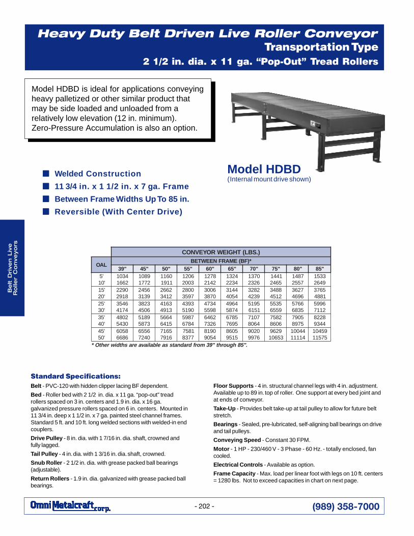
Model HDBD is ideal for applications conveyingheavy palletized or other similar product thatmay be side loaded and unloaded from arelatively low elevation (12 in. minimum).Zero-Pressure Accumulation is also an option.
■■■■■ Welded Construction
■■■■■ 11 3/4 in. x 1 1/2 in. x 7 ga. Frame
■■■■■ Between Frame Widths Up To 85 in.
■■■■■ Reversible (With Center Drive)
Model HDBD(Internal mount drive shown)
).SBL(THGIEWROYEVNOC
LAO*)FB(EMARFNEEWTEB
"93 "54 "05 "55 "06 "56 "07 "57 "08 "58'5'01
43012661
98012771
06111191
60213002
87212412
42314322
07316232
14415642
78417552
33519462
'51'02
09228192
65429313
26622143
00827953
60030783
44134504
28239324
88432154
72636964
56731884
'52'03
64534714
32836054
36143194
39340915
43748955
46944785
59151516
53559556
66755386
69952117
'53'04
20840345
98153785
46655146
78954876
26466237
58765967
70174608
28576068
50975798
82284439
'54'05
85066866
65560427
56176197
18577738
09184509
50685159
02096799
926935601
4400141111
9540157511
."58hguorht"93morfdradnatssaelbaliavaerashtdiwrehtO*
Heavy Duty Belt Driven Live Roller ConveyorTransportation Type
2 1/2 in. dia. x 11 ga. “Pop-Out” Tread Rollers
(989) 358-7000
Be
lt Driv
en L
ive
Ro
ller C
on
ve
yo
rs
- 203 -
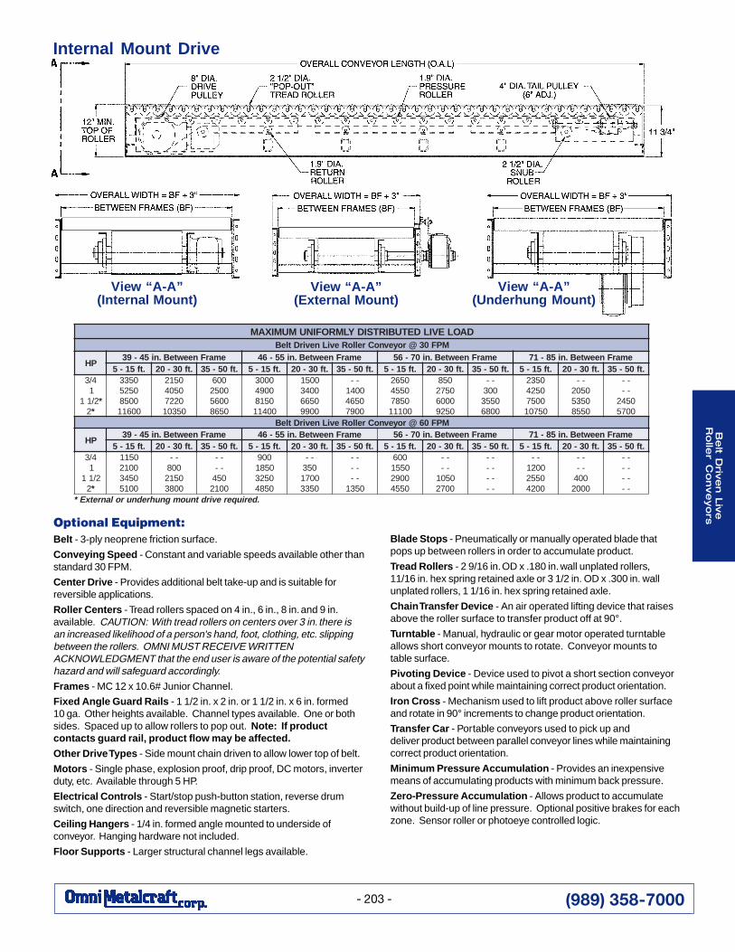
Internal Mount Drive
Optional Equipment:Belt - 3-ply neoprene friction surface.
Conveying Speed - Constant and variable speeds available other thanstandard 30 FPM.
Center Drive - Provides additional belt take-up and is suitable forreversible applications.
Roller Centers - Tread rollers spaced on 4 in., 6 in., 8 in. and 9 in.available. CAUTION: With tread rollers on centers over 3 in. there isan increased likelihood of a person's hand, foot, clothing, etc. slippingbetween the rollers. OMNI MUST RECEIVE WRITTENACKNOWLEDGMENT that the end user is aware of the potential safetyhazard and will safeguard accordingly.
Frames - MC 12 x 10.6# Junior Channel.
Fixed Angle Guard Rails - 1 1/2 in. x 2 in. or 1 1/2 in. x 6 in. formed10 ga. Other heights available. Channel types available. One or bothsides. Spaced up to allow rollers to pop out. Note: If productcontacts guard rail, product flow may be affected.
Other Drive Types - Side mount chain driven to allow lower top of belt.
Motors - Single phase, explosion proof, drip proof, DC motors, inverterduty, etc. Available through 5 HP.
Electrical Controls - Start/stop push-button station, reverse drumswitch, one direction and reversible magnetic starters.
Ceiling Hangers - 1/4 in. formed angle mounted to underside ofconveyor. Hanging hardware not included.
Floor Supports - Larger structural channel legs available.
Blade Stops - Pneumatically or manually operated blade thatpops up between rollers in order to accumulate product.
Tread Rollers - 2 9/16 in. OD x .180 in. wall unplated rollers,11/16 in. hex spring retained axle or 3 1/2 in. OD x .300 in. wallunplated rollers, 1 1/16 in. hex spring retained axle.
Chain Transfer Device - An air operated lifting device that raisesabove the roller surface to transfer product off at 90°.
Turntable - Manual, hydraulic or gear motor operated turntableallows short conveyor mounts to rotate. Conveyor mounts totable surface.
Pivoting Device - Device used to pivot a short section conveyorabout a fixed point while maintaining correct product orientation.
Iron Cross - Mechanism used to lift product above roller surfaceand rotate in 90° increments to change product orientation.
Transfer Car - Portable conveyors used to pick up anddeliver product between parallel conveyor lines while maintainingcorrect product orientation.
Minimum Pressure Accumulation - Provides an inexpensivemeans of accumulating products with minimum back pressure.
Zero-Pressure Accumulation - Allows product to accumulatewithout build-up of line pressure. Optional positive brakes for eachzone. Sensor roller or photoeye controlled logic.
View “A-A”(External Mount)
DAOLEVILDETUBIRTSIDYLMROFINUMUMIXAMMPF03@royevnoCrelloReviLnevirDtleB
PHemarFneewteB.ni54-93 emarFneewteB.ni55-64 emarFneewteB.ni07-65 emarFneewteB.ni58-17
.tf51-5 .tf03-02 .tf05-53 .tf51-5 .tf03-02 .tf05-53 .tf51-5 .tf03-02 .tf05-53 .tf51-5 .tf03-02 .tf05-534/3
12/11 *
2*
05330525005800611
05120504022705301
006005200650568
00030094051800411
0051004305660099
--004105640097
05620554058700111
058057200060529
--00305530086
05320524005705701
--050205350558
----05420075
MPF06@royevnoCrelloReviLnevirDtleB
PHemarFneewteB.ni54-93 emarFneewteB.ni55-64 emarFneewteB.ni07-65 emarFneewteB.ni58-17
.tf51-5 .tf03-02 .tf05-53 .tf51-5 .tf03-02 .tf05-53 .tf51-5 .tf03-02 .tf05-53 .tf51-5 .tf03-02 .tf05-534/3
12/11
2*
0511001205430015
--00805120083
----0540012
009058105230584
--05300710533
------0531
006055100920554
----05010072
--------
--002105520024
----0040002
--------
.deriuqerevirdtnuomgnuhrednurolanretxE*
View “A-A”(Internal Mount)
View “A-A”(Underhung Mount)
(989) 358-7000
Be
lt D
rive
n L
ive
Ro
ller
Co
nve
yo
rs
- 204 -
Pressure Sheave - 3 in. dia. V-belt sheave with 1/2 in. bore.
Idler Sheave - 3 in. dia. V-belt sheave with 1/2 in. bore or 3 in. dia. flatbelt sheave with 1/2 in. bore.
Take-Up - Screw take-up with 3 in. dia. V-belt sheave with 1/2 in.bore. Provides take-up to allow for future belt tension.
Bearings - Sealed, pre-lubricated, self-aligning ball bearings.
Conveying Speed - Constant 60 FPM.
Speed Reduction - Sealed worm gear “C” face speed reducer withNo. 50 chain to driving sheave.
Motor - 1/2 HP - 230/460 V - 3 Phase - 60 Hz. - totally enclosed, fancooled.Electrical Controls - Available as option.
Capacity - 500 lbs. total live load.
Standard Specifications:Belt - Endless “B” section V-belt.
Frame - 10 in. deep x 1 1/2 in. x 10 ga. galvanized steel channelframes with bolt on end couplers on tangents. 8 in. deep x1 1/2 in. x 10 ga. galvanized steel channel frames on curve.Outside rail of curve has “triple-punched” hex holes toallow skewing of rollers which affects product tracking.Curve Roller - 2 1/2 in. dia. tapered to 1 11/16 in. dia. x 14 ga.zinc-plated rollers on 3 in. nom. centers. Grease-packed ballbearings. Curve rollers do not represent true taper.Tangent Roller - 1.9 in. dia. x 16 ga. galvanized rollers on3 in. centers. Grease-packed ball bearings.
Floor Supports - Adjustable 32 1/2 in. to 36 1/2 in. from floor totop of rollers. One support at ends of conveyor and one singleleg support at center of curve.
Driving Sheave - 5 3/4 in. dia. V-belt sheave with 1 in. bore.
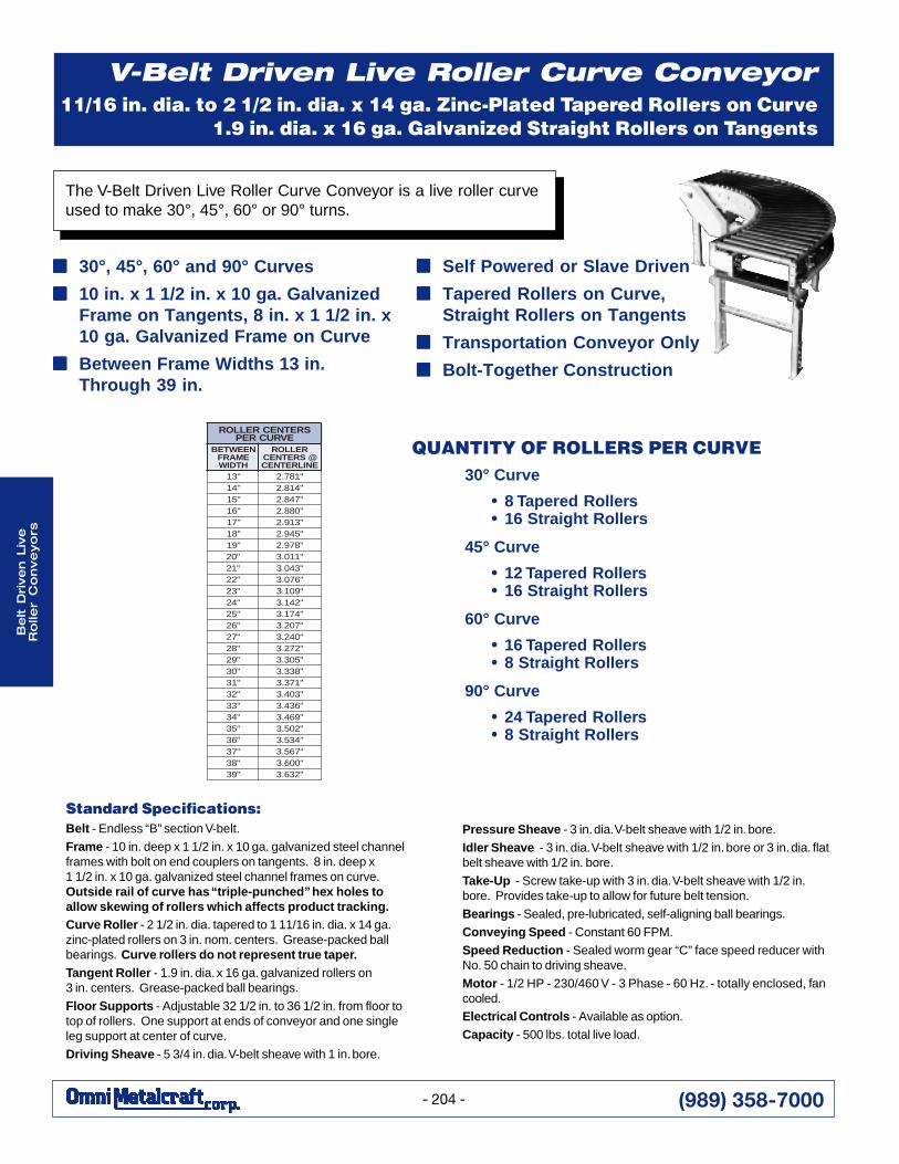
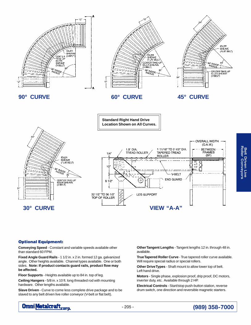
The V-Belt Driven Live Roller Curve Conveyor is a live roller curveused to make 30°, 45°, 60° or 90° turns.
■■■■■ 30°, 45°, 60° and 90° Curves
■■■■■ 10 in. x 1 1/2 in. x 10 ga. GalvanizedFrame on Tangents, 8 in. x 1 1/2 in. x10 ga. Galvanized Frame on Curve
■■■■■ Between Frame Widths 13 in.Through 39 in.
V-Belt Driven Live Roller Curve Conveyor1 11/16 in. dia. to 2 1/2 in. dia. x 14 ga. Zinc-Plated Tapered Rollers on Curve
1.9 in. dia. x 16 ga. Galvanized Straight Rollers on Tangents
■■■■■ Self Powered or Slave Driven
■■■■■ Tapered Rollers on Curve,Straight Rollers on Tangents
■■■■■ Transportation Conveyor Only
■■■■■ Bolt-Together Construction
SRETNECRELLOREVRUCREP
NEEWTEBEMARFHTDIW
RELLOR@SRETNECENILRETNEC
"31 "187.2"41 "418.2"51 "748.2"61 "088.2"71 "319.2"81 "549.2"91 "879.2"02 "110.3"12 "340.3"22 "670.3"32 "901.3"42 "241.3"52 "471.3"62 "702.3"72 "042.3"82 "272.3"92 "503.3"03 "833.3"13 "173.3"23 "304.3"33 "634.3"43 "964.3"53 "205.3"63 "435.3"73 "765.3"83 "006.3"93 "236.3
QUANTITY OF ROLLERS PER CURVE30° Curve
• 8 Tapered Rollers• 16 Straight Rollers
45° Curve
• 12 Tapered Rollers• 16 Straight Rollers
60° Curve
• 16 Tapered Rollers• 8 Straight Rollers
90° Curve
• 24 Tapered Rollers• 8 Straight Rollers
(989) 358-7000
Be
lt Driv
en L
ive
Ro
ller C
on
ve
yo
rs
- 205 -
Optional Equipment:Conveying Speed - Constant and variable speeds available otherthan standard 60 FPM.
Fixed Angle Guard Rails - 1 1/2 in. x 2 in. formed 12 ga. galvanizedangle. Other heights available. Channel types available. One or bothsides. Note: If product contacts guard rails, product flow maybe affected.
Floor Supports - Heights available up to 84 in. top of leg.
Ceiling Hangers - 5/8 in. x 10 ft. long threaded rod with mountinghardware. Other lengths available.
Slave Driven - Curve to come less complete drive package and to beslaved to any belt driven live roller conveyor (V-belt or flat belt).
Other Tangent Lengths - Tangent lengths 12 in. through 48 in.available.
True Tapered Roller Curve - True tapered roller curve available.Will require special radius or special rollers.
Other Drive Types - Shaft mount to allow lower top of belt.Left hand drive.
Motors - Single phase, explosion proof, drip proof, DC motors,inverter duty, etc. Available through 2 HP.
Electrical Controls - Start/stop push-button station, reversedrum switch, one direction and reversible magnetic starters.
30° CURVE
45° CURVE60° CURVE90° CURVE
VIEW “A-A”
Standard Right Hand DriveLocation Shown on All Curves.
(989) 358-7000
Be
lt D
rive
n L
ive
Ro
ller
Co
nve
yo
rs
- 206 -
Minimum Pressure Accumulation Type
Take-Up - Screw take-up with 4 in. dia. V-belt sheave with1/2 in. bore. Provides take-up to allow for future belt tension.
Bearings - Sealed, pre-lubricated, self-aligning ball bearings.
Conveying Speed - Constant 60 FPM.
Speed Reduction - Sealed worm gear “C” face speed reducer withNo. 50 chain to driving sheave.
Motor - 1/2 HP - 230/460 V - 3 Phase - 60 Hz. - totally enclosed, fancooled.
Electrical Controls - Available as option.
Capacity - 500 lbs. total live load.
Standard Specifications:Belt - Endless “B” section V-belt.
Frame - 10 in. deep x 1 1/2 in. x 10 ga. galvanized steel channelframes with bolt on end couplers on head section. 8 in. deep x1 1/2 in. x 10 ga. galvanized steel channel frames on spur.
Roller - 1.9 in. dia. x 16 ga. galvanized rollers on 3 in. centers.Grease-packed ball bearings.
Floor Supports - Adjustable 32 1/2 in. to 36 1/2 in. from floor totop of rollers. One support at end of conveyor.
Driving Sheave - 5 3/4 in. dia. V-belt sheave with 1 in. bore.
Pressure Sheave - 3 in. dia. V-belt sheave with 1/2 in. bore.
Snub Return Sheave - 3 in. dia. flat belt sheave with 1 in. bore.
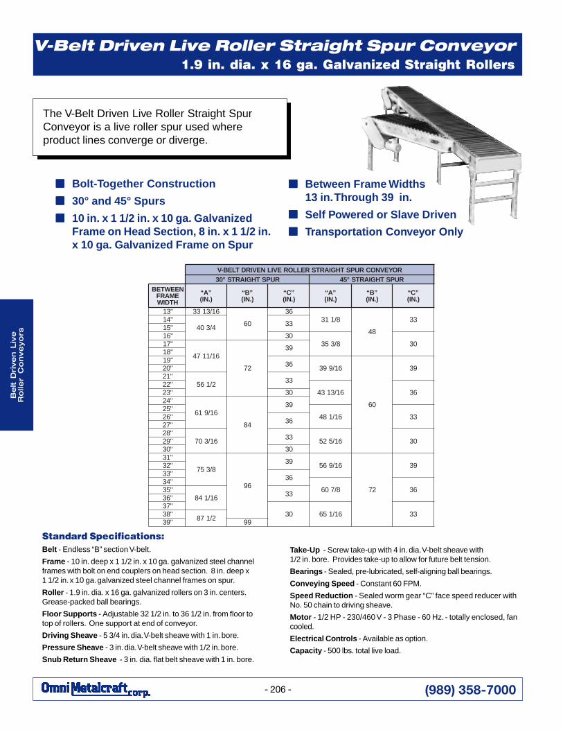
The V-Belt Driven Live Roller Straight SpurConveyor is a live roller spur used whereproduct lines converge or diverge.
V-Belt Driven Live Roller Straight Spur Conveyor1.9 in. dia. x 16 ga. Galvanized Straight Rollers
■■■■■ Bolt-Together Construction
■■■■■ 30° and 45° Spurs
■■■■■ 10 in. x 1 1/2 in. x 10 ga. GalvanizedFrame on Head Section, 8 in. x 1 1/2 in.x 10 ga. Galvanized Frame on Spur
■■■■■ Between Frame Widths13 in. Through 39 in.
■■■■■ Self Powered or Slave Driven
■■■■■ Transportation Conveyor Only
ROYEVNOCRUPSTHGIARTSRELLOREVILNEVIRDTLEB-VRUPSTHGIARTS°03 RUPSTHGIARTS°54
NEEWTEBEMARFHTDIW
”A“).NI(
”B“).NI(
”C“).NI(
”A“).NI(
”B“).NI(
”C“).NI(
"31 61/3133
06
638/113
84
33"414/304 33"51
"61 038/353 03"71
61/1174
27
93"81"91 63 61/993
06
93"02"12
2/165 33"2261/3134 63"32 03
"42
61/916
48
93"5261/184 33"62 63"72
"8261/307 33 61/525 03"92
"03 03"13
8/357
69
93 61/965
27
93"23"33 63"43
8/706 63"5361/148 33"63
"7303 61/156 33"83 2/178"93 99
(989) 358-7000
Be
lt Driv
en L
ive
Ro
ller C
on
ve
yo
rs
- 207 -
Optional Equipment:Conveying Speed - Constant and variable speeds available otherthan 60 FPM.
Fixed Angle Guard Rails - 1 1/2 in. x 2 in. formed 12 ga. galvanizedangle. Other heights available. Channel types available. One or bothsides. Note: If product contacts guard rails, product flow maybe affected.
Floor Supports - Heights available up to 84 in. top of leg.
Ceiling Hangers - 5/8 in. x 10 ft. long threaded rod with mountinghardware. Other lengths available.
Traffic Cop - Controls product flow where two lines converge,eliminating product collisions. Only one line is open at a given time.
Turning Wheel - Used on converging lines to insure properproduct orientation when product is transferred onto a main line.
Slave Driven - Spur to come less complete drive packageand to be slaved to any belt driven live roller conveyor. (V-belt orflat belt.)
Other Drive Types - Shaft mount to allow lower top of belt.
Motors - Single phase, explosion proof, drip proof, DC motors,inverter duty, etc. Available through 2 HP.
Electrical Controls - Start/stop push-button station, reverse drumswitch, one direction and reversible magnetic starters.
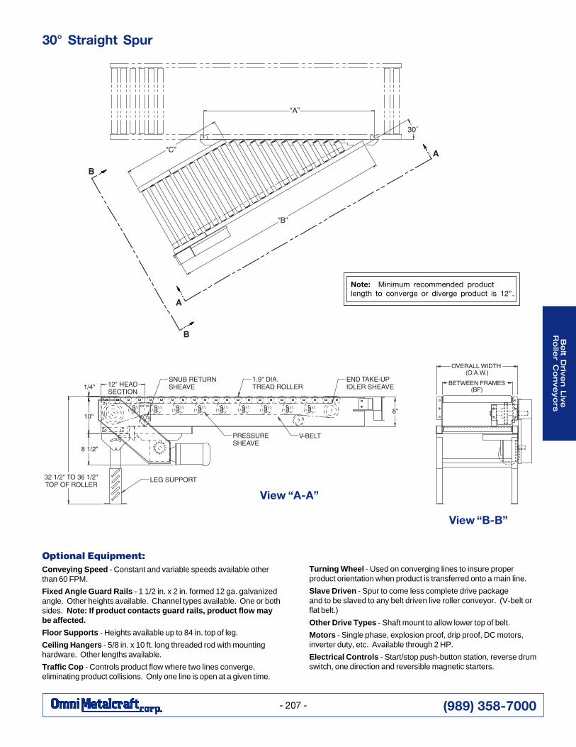
View “B-B”
30° Straight Spur
Note: Minimum recommended productlength to converge or diverge product is 12".
View “A-A”
(989) 358-7000
Be
lt D
rive
n L
ive
Ro
ller
Co
nve
yo
rs
- 208 -
Pressure Sheave - 3 in. dia. V-belt sheave with 1/2 in. bore.
Snub Return Sheave - 3 in. dia. flat belt sheave with 1 in. bore.
Take-Up - Screw take-ups with 3 in. dia. V-belt sheave with1/2 in. bore and 4 in. dia. V-belt sheave with 1/2 in. bore. Providestake-up to allow for future belt tension.
Bearings - Sealed, pre-lubricated, self-aligning ball bearings.
Conveying Speed - Constant 60 FPM.
Speed Reduction - Sealed worm gear “C” face speed reducer withNo. 50 chain to driving sheave.
Motor - 1/2 HP - 230/460 V - 3 Phase - 60 Hz. - totally enclosed, fancooled.
Electrical Controls - Available as option.
Capacity - 500 lbs. total live load.
Standard Specifications:Belt - Endless “B” section V-belt.
Frame - 10 in. deep x 1 1/2 in. x 10 ga. galvanized steel channelframes with bolt on end couplers on tangents. 8 in. deep x 1 1/2 in.x 10 ga. galvanized steel channel frames on spur and curve.Outside rail of curve has “triple-punched” hex holes to allowskewing of rollers which affects product tracking.Curve Roller - 2 1/2 in. dia. tapered to 1 11/16 in. dia. x 14 ga.zinc-plated rollers on 3 in. nom. centers. Grease-packed ballbearings. Curve rollers do not represent true taper.Spur and Tangent Roller - 1.9 in. dia. x 16 ga. galvanized rollerson 3 in. centers. Grease-packed ball bearings.
Floor Supports - Adjustable 32 1/2 in. to 36 1/2 in. from floorto top of rollers. One support at both ends of curve.
Driving Sheave - 5 3/4 in. dia. V-belt sheave with 1 in. bore.
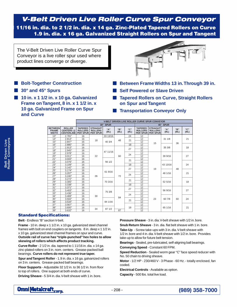
The V-Belt Driven Live Roller Curve SpurConveyor is a live roller spur used whereproduct lines converge or diverge.
■■■■■ Bolt-Together Construction
■■■■■ 30° and 45° Spurs
■■■■■ 10 in. x 1 1/2 in. x 10 ga. GalvanizedFrame on Tangent, 8 in. x 1 1/2 in. x10 ga. Galvanized Frame on Spurand Curve
V-Belt Driven Live Roller Curve Spur Conveyor
■■■■■ Between Frame Widths 13 in. Through 39 in.
■■■■■ Self Powered or Slave Driven
■■■■■ Tapered Rollers on Curve, Straight Rollerson Spur and Tangent
■■■■■ Transportation Conveyor Only
1 11/16 in. dia. to 2 1/2 in. dia. x 14 ga. Zinc-Plated Tapered Rollers on Curve1.9 in. dia. x 16 ga. Galvanized Straight Rollers on Spur and Tangent
ROYEVNOCRUPSEVRUCRELLOREVILNEVIRDTLEB-VRUPS°03 RUPS°54
NEEWTEBEMARFHTDIW
RELLOR@SRETNECENILRETNEC
DEREPATSRELLORRUPSREP
THGIARTSSRELLORRUPSREP
”A“).NI(
”B“).NI(
”C“).NI(
DEREPATSRELLORRUPSREP
THGIARTSSRELLORRUPSREP
”A“).NI(
”B“).NI(
”C“).NI(
"31 "187.2 61
81
61/3133
84
42 21
51
8/113
63
12"41 "418.2 614/304 12 21
"51 "748.2 61 21"61 "088.2 61 81 21
8/353 81"71 "319.2 61
22
61/1174
06
72 21"81 "549.2 61 21"91 "879.2 61 42 21
91
61/993
84
72"02 "110.3 61 21"12 "340.3 61
2/165 12 21"22 "670.3 61 21
61/3134 42"32 "901.3 61 81 21"42 "241.3 61
62
61/916
27
72 21"52 "471.3 61 21
61/184 12"62 "702.3 61 42 21"72 "042.3 61 21"82 "272.3 61
61/307 12 2161/525 81"92 "503.3 61 21
"03 "833.3 61 81 21"13 "173.3 61
03
8/357
48
72 21
32
61/965
06
72"23 "304.3 61 21"33 "634.3 61 42 21"43 "964.3 61 21
8/706 42"53 "205.3 6161/148 12 21
"63 "435.3 61 21"73 "765.3 61
8121
61/156 12"83 "006.3 61 43 2/178 21"93 "236.3 61 78 21
(989) 358-7000
Be
lt Driv
en L
ive
Ro
ller C
on
ve
yo
rs
- 209 -
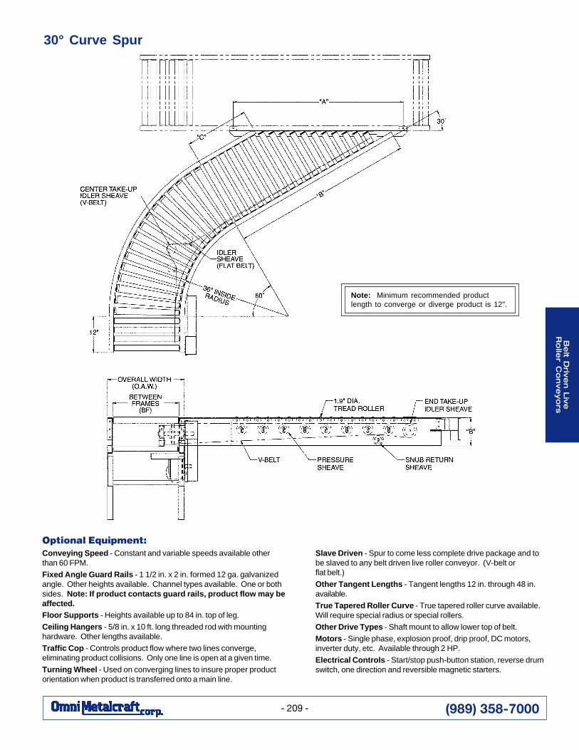
Optional Equipment:Conveying Speed - Constant and variable speeds available otherthan 60 FPM.
Fixed Angle Guard Rails - 1 1/2 in. x 2 in. formed 12 ga. galvanizedangle. Other heights available. Channel types available. One or bothsides. Note: If product contacts guard rails, product flow may beaffected.Floor Supports - Heights available up to 84 in. top of leg.
Ceiling Hangers - 5/8 in. x 10 ft. long threaded rod with mountinghardware. Other lengths available.
Traffic Cop - Controls product flow where two lines converge,eliminating product collisions. Only one line is open at a given time.
Turning Wheel - Used on converging lines to insure proper productorientation when product is transferred onto a main line.
30° Curve Spur
Note: Minimum recommended productlength to converge or diverge product is 12".
Slave Driven - Spur to come less complete drive package and tobe slaved to any belt driven live roller conveyor. (V-belt orflat belt.)
Other Tangent Lengths - Tangent lengths 12 in. through 48 in.available.
True Tapered Roller Curve - True tapered roller curve available.Will require special radius or special rollers.
Other Drive Types - Shaft mount to allow lower top of belt.
Motors - Single phase, explosion proof, drip proof, DC motors,inverter duty, etc. Available through 2 HP.
Electrical Controls - Start/stop push-button station, reverse drumswitch, one direction and reversible magnetic starters.

(989) 358-7000
Be
lt D
rive
n L
ive
Ro
ller
Co
nve
yo
rs
- 210 -
Recommended