Magellan® 8300/8400
Product Reference Guide
Datalogic Scanning, Inc.959 Terry StreetEugene, Oregon 97402Telephone: (541) 683-5700Fax: (541) 345-7140An Unpublished Work - All rights reserved. No part of the contents of this documentation or the procedures described therein may be reproduced or transmitted in any form or by any means without prior written permission of Datalogic Scanning, Inc. or its subsidiaries or affiliates ("Datalogic" or “Datalogic Scanning”). Owners of Datalogic products are hereby granted a non-exclusive, revocable license to reproduce and transmit this documentation for the purchaser's own internal business purposes. Purchaser shall not remove or alter any proprietary notices, including copyright notices, contained in this documentation and shall ensure that all notices appear on any repro-ductions of the documentation.Should future revisions of this manual be published, you can acquire printed versions by contacting your Datalogic representative. Electronic versions may either be downloadable from the Datalogic website (www.scanning.data-logic.com) or provided on appropriate media. If you visit our website and would like to make comments or sugges-tions about this or other Datalogic publications, please let us know via the "Contact Datalogic" page.
Disclaimer
Datalogic has taken reasonable measures to provide information in this manual that is complete and accurate, however, Datalogic reserves the right to change any specification at any time without prior notice.Datalogic is a registered trademark of Datalogic S.p.A. in many countries and the Datalogic logo is a trademark of Datalogic S.p.A. All other brand and product names referred to herein may be trademarks of their respective own-ers.
This product may be covered by one or more of the following patents: 4603262 • 4639606 • 4652750 • 4672215 • 4699447 • 4709369 • 4749879 • 4786798 • 4792666 • 4794240 • 4798943 • 4799164 • 4820911 • 4845349 • 4861972 • 4861973 • 4866257 • 4868836 • 4879456 • 4939355 • 4939356 • 4943127 • 4963719 • 4971176 • 4971177 • 4991692 • 5001406 • 5015831 • 5019697 • 5019698 • 5086879 • 5115120 • 5144118 • 5146463 • 5179270 • 5198649 • 5200597 • 5202784 • 5208449 • 5210397 • 5212371 • 5212372 • 5214270 • 5229590 • 5231293 • 5232185 • 5233169 • 5235168 • 5237161 • 5237162 • 5239165 • 5247161 • 5256864 • 5258604 • 5258699 • 5260554 • 5274219 • 5296689 • 5298728 • 5311000 • 5327451 • 5329103 • 5330370 • 5347113 • 5347121 • 5371361 • 5382783 • 5386105 • 5389917 • 5410108 • 5420410 • 5422472 • 5426507 • 5438187 • 5440110 • 5440111 • 5446271 • 5446749 • 5448050 • 5463211 • 5475206 • 5475207 • 5479011 • 5481098 • 5491328 • 5493108 • 5504350 • 5508505 • 5512740 • 5541397 • 5552593 • 5557095 • 5563402 • 5565668 • 5576531 • 5581707 • 5594231 • 5594441 • 5598070 • 5602376 • 5608201 • 5608399 • 5612529 • 5629510 • 5635699 • 5641958 • 5646391 • 5661435 • 5664231 • 5666045 • 5671374 • 5675138 • 5682028 • 5686716 • 5696370 • 5703347 • 5705802 • 5714750 • 5717194 • 5723852 • 5750976 • 5767502 • 5770847 • 5786581 • 5786585 • 5787103 • 5789732 • 5796222 • 5804809 • 5814803 • 5814804 • 5821721 • 5822343 • 5825009 • 5834708 • 5834750 • 5837983 • 5837988 • 5852286 • 5864129 • 5869827 • 5874722 • 5883370 • 5905249 • 5907147 • 5923023 • 5925868 • 5929421 • 5945670 • 5959284 • 5962838 • 5979769 • 6000619 • 6006991 • 6012639 • 6016135 • 6024284 • 6041374 • 6042012 • 6045044 • 6047889 • 6047894 • 6056198 • 6065676 • 6069696 • 6073849 • 6073851 • 6094288 • 6112993 • 6129279 • 6129282 • 6134039 • 6142376 • 6152368 • 6152372 • 6155488 • 6166375 • 6169614 • 6173894 • 6176429 • 6188500 • 6189784 • 6213397 • 6223986 • 6230975 • 6230976 • 6244510 • 6259545 • 6260763 • 6266175 • 6273336 • 6276605 • 6279829 • 6290134 • 6290135 • 6293467 • 6303927 • 6311895 • 6318634 • 6328216 • 6332576 • 6332577 • 6343741 • 6454168 • 6478224 • 6568598 • 6578765 • 6705527 • 6857567 • 6974084 • 6991169 • 7051940 • 7170414 • 7172123 • 7201322 • 7204422 • 7215493 • 7224540 • 7234641 • 7243850 • 7374092 • 601 26 118.6 • AU703547 • D312631 • D313590 • D320011 • D320012 • D323492 • D330707 • D330708 • D349109 • D350127 • D350735 • D351149 • D351150 • D352936 • D352937 • D352938 • D352939 • D358588• D361565 • D372234 • D374630 • D374869 • D375493 • D376357 • D377345 • D377346 • D377347 • D377348 • D388075 • D446524 • EP0256296 • EP0260155 • EP0260156 • EP0295936 • EP0325469 • EP0349770 • EP0368254 • EP0442215 • EP0498366 • EP0531645 • EP0663643 • EP0698251 • EP01330772 • GB2252333 • GB2284086 • GB2301691 • GB2304954 • GB2307093 • GB2308267 • GB2308678 • GB2319103 • GB2333163 • GB2343079 • GB2344486 • GB2345568 • GB2354340 • ISR107546 • ISR118507 • ISR118508 • JP1962823 • JP1971216 • JP2513442 • JP2732459 • JP2829331 • JP2953593 • JP2964278 • MEX185552 • MEX187245 • RE37166 • RE40.071 • Other Pat-ents Pending
Product Reference Guide i
Table of Contents
Chapter 1. Introduction .................................................................................... 1-1Manual Overview ..........................................................................................................1-1
How to Use This Manual ..........................................................................................1-2Technical Support .........................................................................................................1-4
Datalogic Website Support .......................................................................................1-4Datalogic Website TekForum ....................................................................................1-4Reseller Technical Support .......................................................................................1-4Telephone Technical Support ....................................................................................1-4
Scanner and Scanner/Scale Nomenclature .......................................................................1-5Connections .................................................................................................................1-6Physical Parameters ......................................................................................................1-7
Scanning ...............................................................................................................1-7Deactivating EAS Labels ..........................................................................................1-7Weighing ...............................................................................................................1-8Warm-Up Time .......................................................................................................1-9
Electrical Specifications ................................................................................................1-10Power Supply .......................................................................................................1-11
Laser and Product Safety .............................................................................................1-12Canadian Notice ...................................................................................................1-13
Labeling ....................................................................................................................1-14Agency Compliances ...................................................................................................1-15Bar Codes Supported ..................................................................................................1-17
Retail Codes ........................................................................................................1-17Industrial Codes ...................................................................................................1-17Dual Bar Codes for Japan (2 label read) ...................................................................1-18
Chapter 2. Site Preparation and Installation..................................................... 2-1Models ........................................................................................................................2-2Pre-Installation Considerations .......................................................................................2-3Checkstand Design .......................................................................................................2-4Scanner Installation ......................................................................................................2-5Scanner Maintenance ....................................................................................................2-5References ...................................................................................................................2-5Scanner Usage .............................................................................................................2-5Site Preparation Overview ..............................................................................................2-6Ventilation and Spacing .................................................................................................2-8Service Access ...........................................................................................................2-10Power Installation .......................................................................................................2-11
Grounding ...........................................................................................................2-11Checkstand Preparation ...............................................................................................2-12
Liquid Spills and Moisture ......................................................................................2-13Counter Cutout ...........................................................................................................2-13
Checkstand Mounting ............................................................................................2-21Checkstand Vibration ............................................................................................2-21
Installation Overview ...................................................................................................2-21Unpacking ...........................................................................................................2-22
ii Magellan® 8300/8400
Operational Verification .........................................................................................2-23Diagnostic Modes ..................................................................................................2-26Cables & Connections ............................................................................................2-27
Remote Scale Display Placement/Installation ..................................................................2-29Lighting Considerations .........................................................................................2-29Viewing Angle ......................................................................................................2-30Remote Display Cabling .........................................................................................2-31Placing and Installing the Remote Scale Display ........................................................2-31Changing Weighing Modes .....................................................................................2-34
Set-Up & Installation ...................................................................................................2-34Set-up ................................................................................................................2-34Installation ..........................................................................................................2-36Adaptive Scale Platter Option .................................................................................2-38
System Power-Up Recap ..............................................................................................2-39
Chapter 3. Operation and Maintenance ............................................................ 3-1Scanning Items ..................................................................................................... 3-1Deactivating Security Labels .................................................................................... 3-3Proper Weighing Technique ..................................................................................... 3-4
Operational Controls ..................................................................................................... 3-5Operational Modes ....................................................................................................... 3-5
Power-Up/Selftest & Pre-Operation ........................................................................... 3-5Operating Mode ..................................................................................................... 3-7
Additional Functions ..................................................................................................... 3-8Programming ........................................................................................................ 3-8Diagnostic Mode .................................................................................................... 3-8Scanner and Scale Reset ........................................................................................ 3-9Scale Adjustments ................................................................................................. 3-9
Operational Maintenance ..............................................................................................3-11Vertical Scan Window Replacement .........................................................................3-12Horizontal Scan Window Replacement (WRG) ...........................................................3-15
Chapter 4. Problem Isolation ........................................................................... 4-1Diagnostic Procedures .................................................................................................. 4-2Error Codes ................................................................................................................. 4-3Scale Error Reporting ................................................................................................... 4-6Flowcharts .................................................................................................................. 4-7
Chapter 5. Calibration ...................................................................................... 5-1Description of Calibration Sequence ................................................................................ 5-2Motion Test ................................................................................................................. 5-3Automatic Zero Tracking Test ........................................................................................ 5-3Preparing the Scanner/Scale for Calibration ..................................................................... 5-4Calibrating the Scale (Pounds & Kilograms) ..................................................................... 5-4Calibration Verification (U.S. Pounds) ............................................................................. 5-7
Increasing-Load Test (Phase 1) ............................................................................... 5-7Shift Test .............................................................................................................. 5-8Increasing- Load Test (Phase 2) .............................................................................. 5-9Blanking Test ........................................................................................................ 5-9Decreasing-Load Test ............................................................................................5-10Return to Zero Test ...............................................................................................5-10
Product Reference Guide iii
Calibration Verification (Kilograms) ...............................................................................5-11Increasing-Load Test (Phase 1) ..............................................................................5-11Shift Test (Metric) .................................................................................................5-12Increasing- Load Test (Phase 2) .............................................................................5-13Blanking Test .......................................................................................................5-14Decreasing-Load Test ............................................................................................5-15Return to Zero Test ..............................................................................................5-15
Chapter 6. Programming................................................................................... 6-1Introduction to Label Programming .................................................................................6-1Understanding the Basics ...............................................................................................6-1Integrating the Scanner With Your Host System ................................................................6-2
Customizing Your Scanner’s Operation .......................................................................6-2Programming Overview .................................................................................................6-4
Programming via Handheld Device ............................................................................6-4What Is Programming Mode? ....................................................................................6-5Entering and Exiting Programming Mode. ...................................................................6-5Programming Session ..............................................................................................6-6
LED and Beeper Indicators ...........................................................................................6-10If You Make a Mistake... ..............................................................................................6-10
Return to Factory Settings .....................................................................................6-10Test Mode ...........................................................................................................6-11
General Scanner Features ............................................................................................6-12Scanner Button Options .........................................................................................6-12Double Read Timeout ............................................................................................6-14Laser Timeout ......................................................................................................6-16Motor Timeout .....................................................................................................6-18Label Gone Timeout ..............................................................................................6-21Auxiliary Port Mode ...............................................................................................6-24Auxiliary Port Baud Rate ........................................................................................6-26Laser Failure Mode ................................................................................................6-30Productivity Index Reporting (PIR)/Cashier Training (CT) ...........................................6-31
Indication Features .....................................................................................................6-32Green LED Idle State ............................................................................................6-32Power-up Beep Control ..........................................................................................6-33Good Read Beep Control ........................................................................................6-34Good Read Beep Frequency ...................................................................................6-35Good Read Beep Length ........................................................................................6-37Good Read Beep Volume .......................................................................................6-38Good Read When to Indicate ..................................................................................6-41
Scale Features ............................................................................................................6-43Scale Enable ........................................................................................................6-43Scale Country Mode ..............................................................................................6-44Scale Enforced Zero Return ....................................................................................6-46Scale Interface Type .............................................................................................6-49Scale Motion Level Filter ........................................................................................6-51Scale Warm-up Time .............................................................................................6-53Scale LED Enable ..................................................................................................6-55Scale Diagnostics Mode Enable ...............................................................................6-56Scale Calibration Notification ..................................................................................6-57Scale Intercharacter Delay .....................................................................................6-58Remote Display — Enable/Disable ...........................................................................6-59
iv Magellan® 8300/8400
EAS Features ..............................................................................................................6-60EAS Active State ...................................................................................................6-60EAS Timeout ........................................................................................................6-61
Interface Related Features ...........................................................................................6-62Interface Type ......................................................................................................6-62Number of Host Transmission Buffers ......................................................................6-84AIM ID ................................................................................................................6-85Label ID Control ...................................................................................................6-87Global Prefix ........................................................................................................6-90Global Suffix ........................................................................................................6-92Case Conversion ...................................................................................................6-94
IBM Features ..............................................................................................................6-96IBM Interface Options ...........................................................................................6-96IBM Number of Host Resets ....................................................................................6-97IBM Scale Address ................................................................................................6-98IBM Transmit Labels in Code 39 Format .................................................................6-100IBM Label Slicing Control .....................................................................................6-101IBM Maximum Label Slice Length ..........................................................................6-102IBM USB Scanner Device Type ..............................................................................6-103
RS-232 Features .......................................................................................................6-104RS-232 Baud Rate ..............................................................................................6-104RS-232 Number of Data Bits ................................................................................6-108RS-232 Number of Stop Bits .................................................................................6-109RS-232 Parity .....................................................................................................6-110RS-232 Hardware Control ....................................................................................6-112RS-232 Intercharacter Delay ................................................................................6-115RS-232 Software Flow Control ..............................................................................6-116RS-232 Host Echo ...............................................................................................6-117RS-232 Host Echo Quiet Interval ...........................................................................6-118RS-232 Ignore Host Commands ............................................................................6-119RS-232 TTL ........................................................................................................6-120RS-232 TTL Invert ..............................................................................................6-121RS-232 ICL DC1 Character Delay Enable ................................................................6-122RS-232 Team POS ICL Scale ................................................................................6-123RS-232 Beep on ASCII BEL ..................................................................................6-124RS-232 Beep After Weigh ....................................................................................6-125RS-232 Beep on Not on File .................................................................................6-126RS-232 ACK NAK Enable ......................................................................................6-127RS-232 ACK Character ........................................................................................6-129RS-232 NAK Character ........................................................................................6-130RS-232 Retry on ACK NAK Timeout .......................................................................6-131RS-232 ACK NAK Timeout Value ...........................................................................6-132RS-232 ACK NAK Retry Count ...............................................................................6-133RS-232 ACK NAK Error Handling ...........................................................................6-134RS-232 Indicate Transmission Failure ....................................................................6-136
Single Cable RS-232 Options ......................................................................................6-137Single Cable RS-232 Scanner Only Protocol ............................................................6-138Single Cable RS-232 Stale Weight Timeout .............................................................6-139Single Cable RS-232 Scale — Transmit Weight Digits ...............................................6-141Single Cable Manufacturer Extensions ....................................................................6-142Single Cable Pacesetter Plus Enable .......................................................................6-143Single Cable RS-232 RTS CTS Selection .................................................................6-144
Product Reference Guide v
Single Cable RS-232 Use BCC ............................................................................... 6-147Single Cable RS-232 Use ACK/NAK ....................................................................... 6-148Single Cable RS-232 Use STX ............................................................................... 6-149Set Single Cable RS-232 STX Character ................................................................. 6-150Set Single Cable RS-232 ETX Character ................................................................. 6-151
Keyboard Wedge/USB Keyboard Features .................................................................... 6-152Keyboard Interface — Keyboard Layout ................................................................. 6-152Keyboard Interface Quiet Interval ......................................................................... 6-161Keyboard Interface Caps Lock State ...................................................................... 6-162Keyboard Interface — Keyboard Simulation ............................................................ 6-164Keyboard Interface — Control Characters ............................................................... 6-165Keyboard Interface — Intercharacter Delay ............................................................ 6-167
Symbology Programming ........................................................................................... 6-168Coupon Control .................................................................................................. 6-168
UPC-A Enable ........................................................................................................... 6-170UPC-A Number System Character Transmission ...................................................... 6-171UPC-A Check Character Transmission .................................................................... 6-172Expand UPC-A to EAN-13 ..................................................................................... 6-173UPC-A Label ID .................................................................................................. 6-174UPC-A 2-Digit Supplemental Label ID .................................................................... 6-175UPC-A 5-Digit Supplemental Label ID .................................................................... 6-176UPC-A 128 Supplemental Label ID ........................................................................ 6-177UPC-A Minimum Reads ........................................................................................ 6-178
UPC-E Enable ........................................................................................................... 6-180UPC-E Number System Character Transmission ...................................................... 6-181UPC-E Check Character Transmission .................................................................... 6-182Expand UPC-E to UPC-A ....................................................................................... 6-183Expand UPC-E to EAN-13 ..................................................................................... 6-184UPC-E Label ID ................................................................................................... 6-185UPC-E 2-Digit Supplemental Label ID .................................................................... 6-186UPC-E 5-Digit Supplemental Label ID .................................................................... 6-187UPC-E 128 Supplemental Label ID ........................................................................ 6-188UPC-E Minimum Reads ........................................................................................ 6-189
EAN-13 Enable ......................................................................................................... 6-191EAN-13 First Character Transmission ..................................................................... 6-192EAN-13 Check Character Transmission .................................................................. 6-193EAN-13 ISBN Conversion Enable ........................................................................... 6-194EAN 13 Label ID ................................................................................................. 6-195EAN-13 2-Digit Supplemental Label ID .................................................................. 6-196EAN-13 5-Digit Supplemental Label ID .................................................................. 6-197EAN-13 128 Supplemental Label ID ....................................................................... 6-198EAN-13 Minimum Reads ...................................................................................... 6-199Bookland Label ID .............................................................................................. 6-201
EAN-8 Enable ........................................................................................................... 6-202EAN-8 Check Character Transmission .................................................................... 6-203Expand EAN-8 to EAN-13 ..................................................................................... 6-204EAN-8/JAN-8 Guard Insertion ............................................................................... 6-205EAN-8/JAN-8 Guard Substitution ........................................................................... 6-206EAN-8/JAN-8 Both Guards Substitution .................................................................. 6-207EAN-8 Stitch Exact Label Halves ........................................................................... 6-208EAN-8 Stitch Unlike Label Halves .......................................................................... 6-209EAN 8 Label ID ................................................................................................... 6-210
vi Magellan® 8300/8400
EAN-8 2-Digit Supplemental Label ID ....................................................................6-211EAN-8 5-Digit Supplemental Label ID ....................................................................6-212EAN-8 128 Supplemental Label ID ........................................................................6-213EAN-8 Decoding Levels ........................................................................................6-214EAN-8 Minimum Reads ........................................................................................6-217EAN-8 Minimum Segment Length ..........................................................................6-219
Other UPC/EAN Options .............................................................................................6-225Price Weight Check .............................................................................................6-226In-Store Label Minimum Reads .............................................................................6-229Enable EAN Two Label .........................................................................................6-231EAN Two Label Combined Transmission .................................................................6-232UPC/EAN Guard Insertion .....................................................................................6-233UPC/EAN Stitch Exact Label Halves .......................................................................6-234UPC/EAN Stitch Unlike Label Halves ......................................................................6-235UPC/EAN Character Reconstruction .......................................................................6-236EAN Two Label Minimum Reads ............................................................................6-237UPC/EAN Correlation ...........................................................................................6-239UPC/EAN Minimum Segment Length ......................................................................6-240Addons ..............................................................................................................6-246Addon Timer ......................................................................................................6-2502-Digit Add-ons Minimum Reads ...........................................................................6-2515-Digit Add-ons Minimum Reads ...........................................................................6-253Code 128 Add-ons Minimum Reads .......................................................................6-255
GTIN Enable .............................................................................................................6-257GTIN Label ID ....................................................................................................6-258GTIN 2-Digit Supplemental Label ID ......................................................................6-259GTIN 5-Digit Supplemental Label ID ......................................................................6-260GTIN Code 128 Supplemental Label ID ..................................................................6-261
DataBar Omnidirectional Enable ..................................................................................6-262DataBar Omnidirectional/EAN-128 Emulation ..........................................................6-263DataBar Omnidirectional Label ID .........................................................................6-264DataBar Omnidirectional Minimum Reads ...............................................................6-265
DataBar Expanded Enable ..........................................................................................6-267DataBar Expanded EAN-128 Emulation ..................................................................6-268DataBar Expanded Label ID ..................................................................................6-269DataBar Expanded Length Control .........................................................................6-270DataBar Expanded Length 1 .................................................................................6-271DataBar Expanded Length 2 .................................................................................6-272DataBar Expanded Minimum Reads .......................................................................6-273
Code 39 Enable ........................................................................................................6-275Code 39 Start Stop Character Transmission ............................................................6-276Code 39 Check Character Calculation .....................................................................6-277Code 39 Check Character Transmission ..................................................................6-278Code 39 Full ASCII ..............................................................................................6-279Code 39 Label ID ................................................................................................6-280Code 39 Require Quiet Zones ...............................................................................6-281Code 39 Length Control .......................................................................................6-282Code 39 Length 1 ...............................................................................................6-283Code 39 Length 2 ...............................................................................................6-284Code 39 Correlation ............................................................................................6-285Code 39 Stitching ...............................................................................................6-286Code 39 Minimum Reads .....................................................................................6-287
Product Reference Guide vii
Pharmacode 39 Enable .............................................................................................. 6-289Pharmacode 39 Start Stop Character Transmission ................................................. 6-290Pharmacode 39 Check Character Transmission ....................................................... 6-291Pharmacode 39 Label ID ...................................................................................... 6-292
Code 128 Enable ...................................................................................................... 6-293Code 128 Transmit Function Characters ................................................................. 6-294Convert Code 128 to Code 39 ............................................................................... 6-295Code 128 Label ID .............................................................................................. 6-296Code 128 Length Control ..................................................................................... 6-297Code 128 Length 1 ............................................................................................. 6-298Code 128 Length 2 ............................................................................................. 6-299Code 128 Correlation .......................................................................................... 6-300Code 128 Stitching ............................................................................................. 6-302Code 128 Minimum Reads .................................................................................... 6-303
EAN-128 Enable ....................................................................................................... 6-305EAN-128 Label ID ............................................................................................... 6-306
Interleaved 2 of 5 (I 2 of 5) Enable ............................................................................. 6-307I 2 of 5 Check Character Calculation ...................................................................... 6-308I 2 of 5 Check Character Transmission ................................................................... 6-309I 2 of 5 Label ID ................................................................................................. 6-310I 2 of 5 Length Control ........................................................................................ 6-311I 2 of 5 Length 1 ................................................................................................ 6-312I 2 of 5 Length 2 ................................................................................................ 6-313I 2 of 5 Correlation ............................................................................................. 6-314I 2 of 5 Stitching ................................................................................................ 6-315I 2 of 5 Minimum Reads ....................................................................................... 6-316
Standard 2 of 5 (Std 2 of 5) Enable ............................................................................. 6-318Standard 2 of 5 Check Character Calculation .......................................................... 6-319Standard 2 of 5 Check Character Transmission ....................................................... 6-320Standard 2 of 5 Label ID ..................................................................................... 6-321Standard 2 of 5 Length Control ............................................................................. 6-322Standard 2 of 5 Length 1 ..................................................................................... 6-323Standard 2 of 5 Length 2 ..................................................................................... 6-324Standard 2 of 5 Correlation .................................................................................. 6-325Standard 2 of 5 Stitching ..................................................................................... 6-326Standard 2 of 5 Minimum Reads ........................................................................... 6-327
Codabar Enable ........................................................................................................ 6-329Codabar Start Stop Character Transmission ........................................................... 6-330Codabar Start Stop Character Set ......................................................................... 6-331Codabar Start Stop Character Match ..................................................................... 6-333Codabar Check Character Calculation .................................................................... 6-334Codabar Check Character Transmission ................................................................. 6-335Codabar Label ID ................................................................................................ 6-337Codabar Require Quiet Zones ............................................................................... 6-338Codabar Length Control ....................................................................................... 6-339Codabar Length 1 ............................................................................................... 6-340Codabar Length 2 ............................................................................................... 6-341Codabar Correlation ............................................................................................ 6-342Codabar Stitching ............................................................................................... 6-343Codabar Minimum Reads ..................................................................................... 6-344
Code 93 Enable ........................................................................................................ 6-346Code 93 Label ID ................................................................................................ 6-347
viii Magellan® 8300/8400
Code 93 Length Control .......................................................................................6-348Code 93 Length 1 ...............................................................................................6-349Code 93 Length 2 ...............................................................................................6-350Code 93 Correlation ............................................................................................6-351Code 93 Stitching ...............................................................................................6-352Code 93 Minimum Reads .....................................................................................6-353
MSI/Plessey Enable ...................................................................................................6-355MSI/Plessey Check Character Calculation ...............................................................6-356MSI/Plessey Number of Check Characters ..............................................................6-357MSI/Plessey Check Character Transmission ............................................................6-358MSI/Plessey Label ID ...........................................................................................6-359MSI/Plessey Length Control ..................................................................................6-360MSI/Plessey Length 1 ..........................................................................................6-361MSI/Plessey Length 2 ..........................................................................................6-362MSI/Plessey Correlation .......................................................................................6-363MSI/Plessey Stitching ..........................................................................................6-364MSI/Plessey Minimum Reads ................................................................................6-365
Appendix A. LED/Beeper Indications & Controls ................................. A-1Controls and Indicators ................................................................................................. A-2
LED and Beeper Indications ..................................................................................... A-2Volume/Tone Push Button ....................................................................................... A-3Scale Zero Push Button .......................................................................................... A-5Calibration Switch .................................................................................................. A-6
Appendix B. Cable Information............................................................ B-1Introduction ................................................................................................................ B-1
General Specifications ............................................................................................ B-1Scanner ................................................................................................................ B-2Scale ................................................................................................................... B-3
IBM Cable Pinout ......................................................................................................... B-4Scanner and Scale ................................................................................................. B-4
IBM USB Cable Pinout ................................................................................................... B-5Scanner and Scale ................................................................................................. B-5
Auxilliary Port .............................................................................................................. B-6External Handheld Input ......................................................................................... B-6
Power Cable ................................................................................................................ B-7Connector Hardware .............................................................................................. B-7
Remote Display ........................................................................................................... B-8Connector Hardware .............................................................................................. B-8
EAS Comm Port (Sensormatic® systems ONLY) ................................................................ B-9EAS Deactivator Control Box Connection ................................................................... B-9
Appendix C. Keypad............................................................................. C-1
Appendix D. Host Commands............................................................... D-1Accepting Commands from an RS-232 Scanner Host ......................................................... D-1
Appendix E. Keyboard Function Key Mappings .................................... E-1Keyboard Model Cross Reference .................................................................................... E-1
Product Reference Guide ix
Appendix F. Factory Defaults............................................................... F-1
Appendix G. Handheld Data Format Requirements .............................. G-1Handheld Data Format Requirements General ............................................................ G-1Datalogic Handheld Data Format Requirements ......................................................... G-2AIM Formats ....................................................................................................... G-10

x Magellan® 8300/8400
NOTES
Product Reference Guide xi
DATALOGIC SCANNING, INC. MAGELLAN® END USER LICENSE AGREEMENT
Notice to End User: The Datalogic Product you have acquired contains embedded Software, which is integral to the product's operation. ThisSoftware is being provided to you under license, subject to the terms and conditions of this Agreement. If you use the Datalogic Product, you willbe deemed to have accepted the terms and conditions of this Agreement. If you do not intend to be bound to the terms of this Agreement, Data-logic is not willing to license the Software to you, you may not use the Datalogic Product or the Software, and you must contact the party fromwhom you acquired the Datalogic Product for instructions.
This End User Software License Agreement ("Agreement") is a legally binding agreement governing the licensing of the Software and Documentation by Dat-alogic,Scanning Holdings, Inc. and its subsidiaries and affiliates ("Datalogic") to the entity or person who has purchased or otherwise acquired a DatalogicProduct ("End User"). For purposes of this Agreement, any software that is associated with a separate end-user license agreement is licensed to you underthe terms of that license agreement. Datalogic and End User hereby agree as follows:
1. Definitions.
1.1 "Documentation" means materials such as user's guides, program reference guides, quick reference guides, manuals, or similar materials associatedwith or related to the Datalogic Product, whether in printed, "online", or other form.
1.2 "Proprietary Information" means: (a) source code, object code, software, documentation, and any related internal design, system design, data basedesign, algorithms, technology, technical data or information, implementation techniques, and trade secrets related to the Software, (b) any other tradesecrets marked appropriately or identified as proprietary or confidential, and (c) any information that End User, under the circumstances, should recog-nize as confidential. Proprietary Information does not include any information that the receiving party can establish was (1) in the public domain, (2)already in the receiving party's possession or rightfully known prior to receipt, (3) rightfully learned from a third party not in violation of any other's pro-prietary rights, or (4) independently developed without access to Proprietary Information.
1.3 "Datalogic Product" means the Datalogic Magellan® 1000i series, Magellan® 1400i series, Magellan® 8100 series, Magellan® 8200 series, Magel-lan® 8300 series, Magellan® 8400 series, Magellan® 8500 series, Magellan® 9500 series, and/or Magellan SL® series scanner and/or scanner/scaleproduct, including all embedded Software in and all Documentation related to such product, which has been purchased or otherwise acquired by EndUser, whether obtained directly or indirectly from Datalogic.
1.4 "Software" means any software or computer programs of Datalogic or its third party licensors in machine readable form which is embedded in the Dat-alogic Product, whether obtained directly or indirectly from Datalogic, including any replacement, update, upgrade, enhancement or modification.
2. Scope Of License Granted.
2.1 Datalogic grants to End User a non-exclusive, non-transferable, perpetual license to use the Software, solely on the Datalogic Product in which it isembedded ("designated Datalogic Product"), in machine-readable form only, solely for End User's internal business purposes. This Agreement doesnot convey ownership of the Software to End User. Title to the Software shall be and remain with Datalogic or the third party from whom Datalogic hasobtained a licensed right. As used in this Agreement, the term "purchase" or its equivalents when applied to the Software shall mean "acquire underlicense." End User is not entitled to receipt or use of the source code to any Software.
2.2 End User shall not copy, modify, decompile, disassemble, reverse engineer, or otherwise reproduce or remanufacture the Software, whether modifiedor unmodified, nor sell, assign, sublicense, distribute, lend, rent, give, or otherwise transfer the Software to any other person or organization, for pur-poses other than as expressly provided in this Agreement, without Datalogic's prior written consent.
3. Transfers, Support.
3.1 Any copying, installing, reproduction, remanufacture, reverse engineering, electronic transfer, or other use of the Software on other than the desig-nated Datalogic Product will be a material breach of this Agreement. However, Datalogic may elect not to terminate this Agreement or the grantedlicenses, but instead may elect to notify End User that End User is deemed to have ordered and accepted a license for each breaching use. End Usershall pay Datalogic the applicable list price for such licenses as of the date of such breach.
3.2 End User shall not sell, assign, sublicense, distribute, lend, rent, give, or otherwise transfer the Datalogic Product to any third party unless such thirdparty agrees with Datalogic in writing to be bound by the terms and conditions of this Agreement. Any such transfer of the Datalogic Product absentsuch agreement shall be null and void.
3.3 End User may obtain support for Software from Datalogic at Datalogic's standard support fees and under Datalogic's standard support terms and con-ditions in effect at the time the support is requested.
4. Intellectual Property.
End User acknowledges that the Software constitutes valuable trade secrets of Datalogic or Datalogic's third party licensors and that the Software is pro-tected by intellectual property laws and treaties. The license set forth in this Agreement does not transfer to End User any ownership of Datalogic's or its thirdparty licensors' copyrights, patents, trademarks, service marks, trade secrets, or other intellectual property rights and End User shall have no right to com-mence any legal actions to obtain such rights. End User shall not remove, modify, or take any other action that would obscure any copyright, trademark,patent marking, or other intellectual property notices contained in or on the Datalogic Product.
5. Proprietary Information.
5.1 End User acknowledges that Proprietary Information is the confidential, proprietary, and trade secret property of Datalogic and Datalogic's third partylicensors and End User acquires no right or interest in any Proprietary Information.
5.2 End User shall not disclose, provide, or otherwise make available the Proprietary Information of Datalogic or its third party licensors to any personother than End User's authorized employees or agents who are under confidentiality agreement, and End User shall not use the Proprietary Informa-tion other than in conjunction with use of the Datalogic Product exclusively for End User's internal business purposes. End User shall take steps toprotect the Proprietary Information no less securely than if it were End User's own intellectual property.
5.3 The provisions of this Proprietary Information Section shall survive and continue for five (5) years after the termination of this Agreement.
6. Limited Warranty.
6.1 Datalogic warrants that, under normal use and operation, the Datalogic Product will conform substantially to the applicable Documentation for theperiod specified in the Documentation. During this period, for all reproducible nonconformities for which Datalogic has been given written notice, Data-logic will use commercially reasonable efforts to remedy nonconformities verified by Datalogic. End User agrees to supply Datalogic with all reasonablyrequested information and assistance necessary to help Datalogic in remedying such nonconformities. For all defects reported to Datalogic within thewarranty period, Datalogic's liability is limited to providing End User with one copy of corrections or responding to End User's problem reports accord-
xii Magellan® 8300/8400
ing to Datalogic's standard assistance practices. Datalogic does not warrant that the product will meet End User's requirements or that use of the prod-uct will be uninterrupted or error free, or that Datalogic's remedial efforts will correct any nonconformance. This limited warranty does not cover anyproduct that has been subjected to damage or abuse, whether intentionally, accidentally, or by neglect, or to unauthorized repair or unauthorized instal-lation, and shall be void if End User modifies the product, uses the product in any manner other than as established in the Documentation, or if EndUser breaches any of the provisions of this Agreement.
6.2 EXCEPT AS PROVIDED IN THIS AGREEMENT, THE DATALOGIC PRODUCT IS PROVIDED "AS IS" AND DATALOGIC MAKES NO WARRANTIESOF ANY KIND, EXPRESS OR IMPLIED, WRITTEN OR ORAL, WITH RESPECT TO THE PRODUCT, AND SPECIFICALLY DISCLAIMS THEIMPLIED WARRANTIES OF MERCHANTABILITY AND FITNESS FOR A PARTICULAR PURPOSE.
7. Infringement.
7.1 Datalogic will defend End User against any claim in a lawsuit that the Datalogic Product furnished hereunder infringe a United States patent or copy-right of a third party and Datalogic will pay any damages finally awarded against End User by a court of competent jurisdiction that are attributable tosuch claim or will pay End User's part of any settlement that is attributable to such claim, provided, that 1) End User notifies Datalogic promptly in writ-ing of the claim, 2) Datalogic controls the defense or settlement of the claim, and 3) End User cooperates fully with Datalogic in such defense or settle-ment. All notices of a claim should be sent to Datalogic Scanning Holdings, Inc., Legal Department, 959 Terry Street, Eugene, OR 97402.
7.2 In the defense or settlement of any such claim, Datalogic may, at its option, 1) procure for End User the right to continue using the Datalogic Product,2) modify the Datalogic Product so that it becomes non-infringing, 3) replace the Datalogic Product with an equivalent product not subject to suchclaim, or 4) provide End User an opportunity to return the Datalogic Product and receive a refund of the purchase price paid, less a reasonable allow-ance for use.
7.3 Datalogic shall have no liability to End User for claims of infringement based upon 1) the use of any Datalogic Product in combination with any productwhich Datalogic has not either furnished or authorized for use with such Datalogic Product 2) the use of any Datalogic Product designed, manufac-tured, or modified to the specifications of End User, or 3) End User's modification of the Datalogic Product without written authorization from Datalogic.
7.4 THE FOREGOING STATES DATALOGIC'S COMPLETE AND ENTIRE OBLIGATION CONCERNING CLAIMS OF PATENT, COPYRIGHT, OR OTHERINTELLECTUAL PROPERTY INFRINGEMENT, CANCELS AND SUPERSEDES ANY PRIOR AGREEMENTS, WHETHER ORAL OR WRITTEN,BETWEEN THE PARTIES CONCERNING SUCH CLAIMS, AND WILL NOT BE MODIFIED OR AMENDED BY ANY PAST, CONTEMPORANEOUS,OR FUTURE AGREEMENTS OR DEALINGS BETWEEN THE PARTIES, WHETHER ORAL OR WRITTEN, EXCEPT AS SET FORTH IN A FUTUREWRITING SIGNED BY BOTH PARTIES.
8. Limitation Of Liability.
EXCEPT AS PROVIDED IN SECTION 7, DATALOGIC SHALL NOT BE LIABLE FOR ANY CLAIMS AGAINST END USER BY ANY OTHER PARTY. IN NOEVENT SHALL DATALOGIC'S LIABILITY FOR DAMAGES, IF ANY, WHETHER BASED UPON CONTRACT, TORT (INCLUDING NEGLIGENCE), PROD-UCT LIABILITY, STRICT LIABILITY, WARRANTY, OR ANY OTHER BASIS, EXCEED THE PRICE OR FEE PAID BY END USER FOR THE DATALOGICPRODUCT. UNDER NO CIRCUMSTANCES SHALL DATALOGIC BE LIABLE TO END USER OR ANY THIRD PARTY FOR LOST PROFITS, LOST DATA,INTERRUPTION OF BUSINESS OR SERVICE, OR FOR ANY OTHER SPECIAL, CONSEQUENTIAL, CONTINGENT, INDIRECT, INCIDENTAL, PUNITIVE,EXEMPLARY, OR OTHER SIMILAR DAMAGES, EVEN IF DATALOGIC HAS BEEN ADVISED OF THE POSSIBILITY OF SUCH DAMAGES.
9. Government Restricted Rights; International Use.
9.1 Use, duplication, or disclosure of the Software by the U.S. Government is subject to the restrictions for computer software developed at privateexpense as set forth in the U.S. Federal Acquisition Regulations at FAR 52.227-14(g), or 52.227-19 or in the Rights in Technical Data and ComputerSoftware clause at DFARS 252.227-7013(c)(1)(ii), whichever is applicable.
9.2 If End User is using the Datalogic Product outside of the United States, End User must comply with the applicable local laws of the country in which theDatalogic Product is used, with U.S. export control laws, and with the English language version of this Agreement. The provisions of the "UnitedNations Convention on International Sale of Goods" shall not apply to this Agreement.
10. Termination.
10.1 Either party may terminate this Agreement or any license granted under this Agreement at any time upon written notice if the other party breaches anyprovision of this Agreement.
10.2 Upon termination of this Agreement, End User immediately shall cease using any non-embedded software and shall return to Datalogic or destroy allnon-embedded software covered by this Agreement, and shall furnish Datalogic with a certificate of compliance with this provision signed by an officeror authorized representative of End User. For embedded software, End User agrees to sign a waiver prepared by Datalogic concerning further use ofthe embedded Software. End User's resumed or continued use of the embedded Software after termination shall constitute End User's agreement tobe bound by the terms and conditions of this Agreement for such use.
11. General Provisions.
11.1 Entire Agreement; Amendment. This document contains the entire agreement between the parties relating to the licensing of the Software and super-sedes all prior or contemporaneous agreements, written or oral, between the parties concerning the licensing of the Software. This Agreement may notbe changed, amended, or modified except by written document signed by Datalogic.
11.2 Notice. All notices required or authorized under this Agreement shall be given in writing, and shall be effective when received, with evidence of receipt.Notices to Datalogic shall be sent to the attention of Contract Administration, Datalogic Scanning Holdings, Inc., 959 Terry Street, Eugene, OR 97402,or such other address as may be specified by Datalogic in writing.
11.3 Waiver. A party's failure to enforce any of the terms and conditions of this Agreement shall not prevent the party's later enforcement of such terms andconditions.
11.4 Governing Law; Venue: This Agreement and the rights of the parties hereunder shall be governed by and construed in accordance with the laws of theState of Oregon U.S.A, without regard to the rules governing conflicts of law. The state or federal courts of the State of Oregon located in either Mult-nomah or Lane counties shall have exclusive jurisdiction over all matters regarding this Agreement, except that Datalogic shall have the right, at itsabsolute discretion, to initiate proceedings in the courts of any other state, country, or territory in which End User resides, or in which any of End User'sassets are located.
11.5 Attorneys’ Fees. In the event an action is brought to enforce the terms and conditions of this Agreement, the prevailing party shall be entitled to reason-able attorneys' fees, both at trial and on appeal.
- END -
Product Reference Guide 1-1
Chapter 1
Introduction
This Product Reference Guide contains comprehensive instructions on scanner or scanner/scale installation. Either model may be termed “scan-ner” for the purpose of simplicity in this manual. Also included are feature configuration using special programming feature bar code labels and advanced user information as described in the following chapter descrip-tions.
Manual OverviewChapter 1, Introduction, outlines the manual’s contents, details features and specifications, provides regulatory and safety information, and lists the symbologies (bar code types) the scanner will read.
Chapter 2, Site Preparation and Installation, presents physical dimen-sions for the scanner or scanner/scale and popular accessories, and pro-vides counter preparation and installation procedures. Cable routing, connection and testing are additionally detailed in this chapter.
Chapter 3, Operation and Maintenance, contains use and maintenance instructions; providing details about operator controls, programming and diagnostic modes, scale “zeroing” and calibration. Scanner and scale rou-tine maintenance is also outlined in this chapter.
Chapter 4, Problem Isolation, outlines the three scanner/scale test modes: Selftest, Operational Tests and Diagnostic Tests. Procedures for system problem and troubleshooting flowcharts to aid in problem resolution are also presented in this chapter.
Chapter 5, Calibration, explains scale calibration and verification proce-dures, including procedures for calibrating the scale in pounds as well as kilograms.
1-2 Magellan® 8300/8400
Chapter 6, Programming, highlights the function(s) of each programma-ble feature and provides a dedicated set of bar codes for configuring scan-ner and scanner/scale features. This chapter is organized by the categories: General Features, Interface Related Features and Symbology Related Fea-tures.
Appendix A, LED/Beeper Indications & Controls, contains tables describ-ing the various functions and indications of the scanner/scale control panel features.
Appendix B, Cable Information, references wire requirements, connector specifications and pinout details for product cabling.
Appendix C, Keypad, is a set of bar codes representing the digits and char-acters required to enter extended programming data needed during certain programming sessions.
Appendix D, Host Commands, furnishes a partial listing of available host commands that can be used with a compatible host interface.
Appendix E, Keyboard Function Key Mappings, summarizes the key-board models, their defined protocol, scancode set, and some unique fea-tures. Other tables in this chapter provide the function key maps associated with each of the scancode sets.
Appendix F, Factory Defaults, lists factory default programmable settings for common interfaces.
Appendix G, Handheld Data Format Requirements, contains application notes describing the general format of data accepted by the scanner through the auxilliary port as transmitted from a handheld scanner.
How to Use This ManualReference the first chapter of this manual for a general description of the product’s features and an outline of the manual’s contents and organiza-tion. View the remaining chapters for procedures regarding scanner or scanner/scale installation, operation, maintenance, calibration and bar code programming.
Manual Overview
Product Reference Guide 1-3
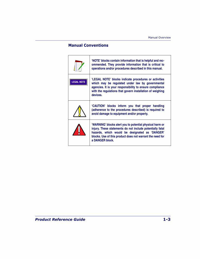
Manual Conventions
‘NOTE’ blocks contain information that is helpful and rec-ommended. They provide information that is critical tooperations and/or procedures described in this manual.
‘LEGAL NOTE’ blocks indicate procedures or activitieswhich may be regulated under law by governmentalagencies. It is your responsibility to ensure compliancewith the regulations that govern installation of weighingdevices.
‘CAUTION’ blocks inform you that proper handling(adherence to the procedures described) is required toavoid damage to equipment and/or property.
‘WARNING’ blocks alert you to potential physical harm orinjury. These statements do not include potentially fatalhazards, which would be designated as ‘DANGER’blocks. Use of this product does not warrant the need fora DANGER block.
LEGAL NOTE
1-4 Magellan® 8300/8400
Technical Support
Datalogic Website SupportThe Datalogic website (www.scanning.datalogic.com) is the complete source for technical support and information for Datalogic products. The site offers the Datalogic TekForum, product support, product registration, warranty information, product manuals, product tech notes, software updates, demos, and instructions for returning products for repair.
Datalogic Website TekForumSearch for information on the TekForum by clicking on the Support link on the Datalogic home page. Browse the TekForum to find answers to your questions about common technical issues.
Reseller Technical SupportAn excellent source for technical assistance and information is an autho-rized Datalogic reseller. A reseller is acquainted with specific types of busi-nesses, application software, and computer systems and can provide individualized assistance.
Telephone Technical SupportIf you do not have internet or email access, you may contact Datalogic technical support at (541) 349-8281.
Scanner and Scanner/Scale Nomenclature
Product Reference Guide 1-5
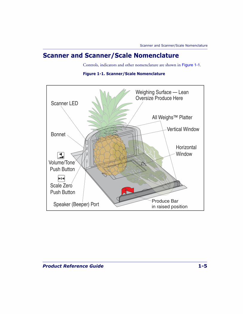
Scanner and Scanner/Scale NomenclatureControls, indicators and other nomenclature are shown in Figure 1-1.
Figure 1-1. Scanner/Scale Nomenclature
Produce Barin raised position
All Weighs™ Platter
Scanner LED
Weighing Surface — LeanOversize Produce Here
Vertical Window
HorizontalWindow
Scale ZeroPush Button
Speaker (Beeper) Port
Volume/TonePush Button
Bonnet
1-6 Magellan® 8300/8400
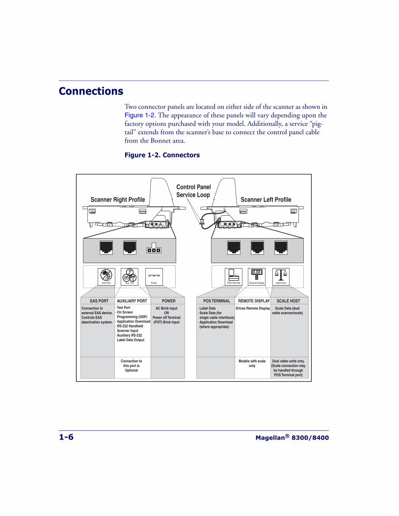
ConnectionsTwo connector panels are located on either side of the scanner as shown in Figure 1-2. The appearance of these panels will vary depending upon the factory options purchased with your model. Additionally, a service “pig-tail” extends from the scanner’s base to connect the control panel cable from the Bonnet area.
Figure 1-2. Connectors
POS TERMINAL REMOTE DISPLAYAUXILIARY PORT SCALE HOSTEAS PORT
Connection tothis port isOptional
Scale Data (dualcable scanner/scale)
Drives Remote Display· Label Data· Scale Data (forsingle cable interfaces)
· Application Download (where appropriate)
· Test Port· On Screen Programming (OSP)· Application Download· RS-232 Handheld Scanner Input· Auxiliary RS-232 Label Data Output
Models with scaleonly
Connection toexternal EAS device.Controls EASdeactivation system.
Dual cable units only.(Scale connection may
be handled throughPOS Terminal port)
POS Terminal Remote DisplayAux. PortEAS Port Scale Host
0.00
POWER
AC Brick InputOR
Power off Terminal(POT) Brick Input
Power
Control PanelService Loop
Scanner Right Profile Scanner Left Profile
Physical Parameters
Product Reference Guide 1-7
Physical ParametersThis chapter provides specifications for performance, environmental and electrical parameters. Reference Chapter 2, Site Preparation and Installa-tion, for physical measurements of all models and some accessories.
ScanningThe scanner has a scan zone between the two windows where the scanner projects laser light in order to scan items. Two separate projections, one from the horizontal window and one from the vertical window, combine to form a zone where bar code labels are read. Refer to Chapter 3, Scan-ning Items, for more information.
Deactivating EAS LabelsDeactivation of EAS (Electronic Article Surveillance) anti-theft labels is an additional function that can be performed by the scanner. More informa-tion about this feature can be referenced under the following topics:
• Chapter 3, Deactivating Security Labels
• Chapter 6, EAS Features
1-8 Magellan® 8300/8400
WeighingSpecifications for scale capacity, settling time, minimum and maximum static weight, zeroing, and warm-up time are given below. For more infor-mation regarding the topic: Proper Weighing Technique, refer to Chapter 3, Operation and Maintenance in this manual.
Rated Weight Capacity
The scale’s operational weight capacity is:
• 30.00 pounds, displayed in 0.01 incrementsOR
• 15.000 kilograms, displayed in 0.005 increments.
Minimum Increment
The minimum weight that can be accurately measured by the scale is 0.01 lb. (0.005 kg).
Maximum Static Weight (Overload)
A maximum static weight of 150 pounds (68 kg) can be sustained by the scale without incurring damage or degrading performance.
Automatic Zero Maintenance
The scale’s software constantly monitors and adjusts the Zero point as long as the deviation is within acceptable limits, while compensating for any debris accumulation or removal. During power-up, the scale automat-ically re-zeros after verifying that all subsystems are functional. Addition-ally, the scale may be manually “zeroed” by pushing the Scale Zero Push Button located at the bottom of the control panel.
Physical Parameters
Product Reference Guide 1-9
Warm-Up TimeThere are two pertinent warm-up times that apply to the scanner or scan-ner/scale:
Thermal Equilibrium
When the unit is moved from a cooler temperature (such as a storage area) to a warmer environment (such as a checkstand location), 60 minutes must be allowed to acclimate the unit to ambient conditions prior to cali-bration or operation.
Power-up
Once installed and powered up, a warm-up time of 15 minutes must be allowed before calibrating or performing weighing operations.
User Configurable Warm-up
The user may configure the unit for a pre-programmed warm-up time that is activated every time the scanner is powered up. During this time, the scale is viewed by the POS terminal as off-line.
NOTE
The two warm-up periods can be performed concurrently, thereby reducingthe total required warm-up time to 60 minutes.
NOTE
Contact Technical Support to learn more about this advanced pro-grammable feature.
1-10 Magellan® 8300/8400
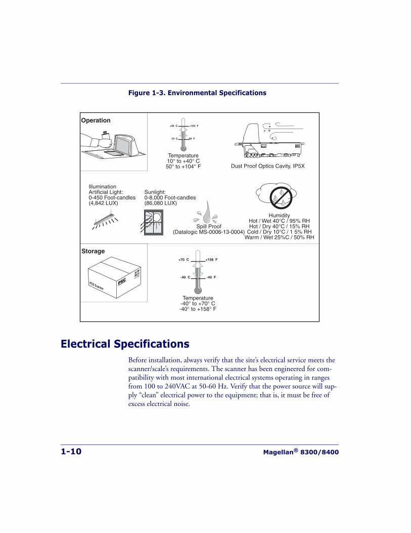
Figure 1-3. Environmental Specifications
Electrical SpecificationsBefore installation, always verify that the site’s electrical service meets the scanner/scale’s requirements. The scanner has been engineered for com-patibility with most international electrical systems operating in ranges from 100 to 240VAC at 50-60 Hz. Verify that the power source will sup-ply “clean” electrical power to the equipment; that is, it must be free of excess electrical noise.
Operation
Storage
+40 C +104 F
10 C 50 F
Temperature10° to +40° C50° to +104° F Dust Proof Optics Cavity, IP5X
+70 C +158 F
-40 C -40 F
Temperature-40° to +70° C-40° to +158° F
IlluminationArtificial Light:0-450 Foot-candles(4,842 LUX)
Sunlight:0-8,000 Foot-candles(86,080 LUX)
POS Scanner
HumidityHot / Wet 40°C / 95% RHHot / Dry 40°C / 15% RH
Cold / Dry 10°C / 1 5% RHWarm / Wet 25%C / 50% RH
Spill Proof(Datalogic MS-0006-13-0004)
Electrical Specifications
Product Reference Guide 1-11
Power Supply
Power Off the Terminal (P.O.T)
Certain units can receive power directly from the terminal (P.O.T.). A USB adapter “brick” connects the scanner to IBM-USB 12V ports.
AC Adapter
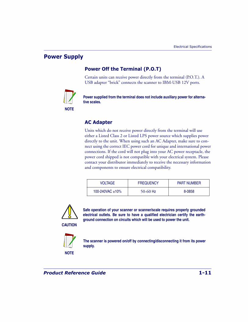
Units which do not receive power directly from the terminal will use either a Listed Class 2 or Listed LPS power source which supplies power directly to the unit. When using such an AC Adapter, make sure to con-nect using the correct IEC power cord for unique and international power connections. If the cord will not plug into your AC power receptacle, the power cord shipped is not compatible with your electrical system. Please contact your distributor immediately to receive the necessary information and components to ensure electrical compatibility.
NOTE
Power supplied from the terminal does not include auxiliary power for alterna-tive scales.
VOLTAGE FREQUENCY PART NUMBER
100-240VAC ±10% 50-60 Hz 8-0858
CAUTION
Safe operation of your scanner or scanner/scale requires properly groundedelectrical outlets. Be sure to have a qualified electrician certify the earth-ground connection on circuits which will be used to power the unit.
NOTE
The scanner is powered on/off by connecting/disconnecting it from its powersupply.
1-12 Magellan® 8300/8400
Laser and Product SafetyLaser safety requirements are based on IEC Standard Publication 60825-1 (2001) and CDRH 21CFR, Chapter 1, Subchapter J and (CDRH) Laser Product Performance Standard, User information [1040.10(h)1]:
• User Maintenance. No user maintenance of the laser system other than cleaning of the scan windows is required.
• Radiant Energy. The scanner is an IEC Class 1 and CDRH IIa laser product. The system uses two embedded Class 3A Visible Laser Diodes (VLDs) operating at 650.0 or 670.0 nm, in an opto-mechanical scanner, resulting in less than 3.9μW radiated power as observed through a 7mm aperture and averaged over 10 seconds. Maximum emitted peak output power at the lower (sealed) window is 850μW. No attempt should be made by the user to remove the protective housing of the scanner/scale.
• Laser Light Viewing. The horizontal and vertical scan windows are the only apertures through which laser light may be observed in this product.
Exposure to the light emitted from the scan windows has been shown not to be harmful. The safety record of bar code scanning is perfect after mil-lions of hours of use worldwide. This safe and efficient use of laser tech-nology has gained wide acceptance in industries throughout the world.
Operators and installers of the unit should observe the following cautions and warnings:
CAUTION
Use of controls, adjustments or performance of procedures other than thosespecified herein may result in hazardous laser light exposure.
The use of optical instruments with the scanner will increase eye hazard.(Optical instruments include binoculars, microscopes, telescopes and mag-nifying glasses. This does not include eyeglasses worn by the user).
To prevent exposure to laser light, do not remove the protective housing ofthe scanner. There are no user-serviceable parts inside your scanner orscanner/scale.
Laser and Product Safety
Product Reference Guide 1-13
Safety precautions to be taken:
Canadian NoticeThis equipment does not exceed the Class B limits for radio noise emis-sions as described in the Radio Interference Regulations of the Canadian Department of Communications.
Le present appareil numerique n’emet pas de bruits radioelectriques depas-sant les limites applicables aux appareils numeriques de la classe B pre-scrites dans le Reglement sur le brouillage radioelectrique edicte par le ministere des Communications du Canada.
CAUTION
No adjustments or alteration of the scanner or scanner/scale housing are tobe attempted by the user.
The failure of the facet wheel motor while the unit is continuing to emit alaser beam causes the emission levels to exceed those for inherently safeoperation. The unit has safeguards to prevent this occurrence. If, however, astationary laser beam is ever emitted, the failing unit should be disconnectedfrom its power supply until repaired by a qualified technician.
WARNING
This equipment has been tested and found to comply with the limits for aClass B digital device pursuant to part 15 of the FCC Rules. These limits aredesigned to provide reasonable protection against harmful interference in aresidential installation. This equipment generates, uses, and can radiateradio frequency energy and, if not installed and used in accordance with theinstructions, may cause harmful interference to radio communications. How-ever, there is no guarantee that interference will not occur in a particularinstallation. If this equipment does cause harmful interference to radio ortelevision reception, which can be determined by turning the equipment offand on, the user is encouraged to try to correct the interference by one ormore of the following measures:
• Reorient or relocate the receiving antenna.• Increase the separation between the equipment and receiver.• Connect the equipment into an outlet on a circuit different from that to
which the receiver is connected.• Consult the dealer or an experienced radio or television technician for
help.
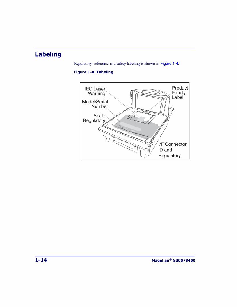
1-14 Magellan® 8300/8400
LabelingRegulatory, reference and safety labeling is shown in Figure 1-4.
Figure 1-4. Labeling
IEC LaserWarning
ProductFamilyLabel
I/F ConnectorID andRegulatory
Model/SerialNumber
ScaleRegulatory
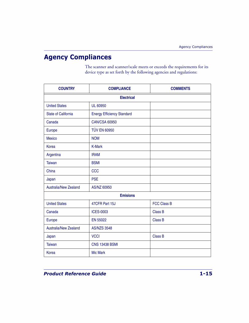
Agency Compliances
Product Reference Guide 1-15
Agency CompliancesThe scanner and scanner/scale meets or exceeds the requirements for its device type as set forth by the following agencies and regulations:
COUNTRY COMPLIANCE COMMENTS
Electrical
United States UL 60950
State of California Energy Efficiency Standard
Canada CAN/CSA 60950
Europe TÜV EN 60950
Mexico NOM
Korea K-Mark
Argentina IRAM
Taiwan BSMI
China CCC
Japan PSE
Australia/New Zealand AS/NZ 60950
Emisions
United States 47CFR Part 15J FCC Class B
Canada ICES-0003 Class B
Europe EN 55022 Class B
Australia/New Zealand AS/NZS 3548
Japan VCCI Class B
Taiwan CNS 13438 BSMI
Korea Mic Mark
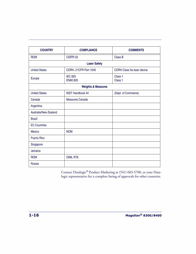
1-16 Magellan® 8300/8400
Contact Datalogic® Product Marketing at (541) 683-5700, or your Data-logic representative for a complete listing of approvals for other countries.
ROW CISPR 22 Class B
Laser Safety
United States CDRH, 21CFR Part 1040 CDRH Class IIa laser device
EuropeIEC 825EN60 825
Class 1Class 1
Weights & Measures
United States NIST Handbook 44 (Dept. of Commerce)
Canada Measures Canada
Argentina
Australia/New Zealand
Brazil
EC Countries
Mexico NOM
Puerto Rico
Singapore
Jamaica
ROW OIML R76
Russia
COUNTRY COMPLIANCE COMMENTS
Bar Codes Supported
Product Reference Guide 1-17
Bar Codes SupportedThe scanner can read/decode the following bar code types (symbologies):
Retail Codes• UPC Versions A & E with full expansion E to A, plus A and E to 13
capability
• UPC Supplementals and Add-ons (Bookland & Coupon code, UPC two character supplemental encodation and UPC five charac-ter supplemental encodation and supplemental C128) with support for conditional add-ons
• DataBar Omnidirectional (formerly RSS-14)
• DataBar Expanded (formerly RSS Expanded) maximum characters 74 numeric or 41 alpha
• DataBar Stacked Omnidirectional (formerly RSS-14 Stacked)
• EAN 8 & 13 with full expansion 8 to 13
• JAN 8 & 13 with full expansion 8 to 13
• UCC/EAN 128
• Italian Pharmacode (Code 39)
• Support GTIN
Industrial Codes• Code 39
• Code 39 full ASCII
• Code 128 (including conversion to Code 39)
• Code 93
• Interleaved 2 of 5 (I 2 of 5)
• Standard 2 of 5
• Codabar
• MSI/Plessey
1-18 Magellan® 8300/8400
Dual Bar Codes for Japan (2 label read)
NOTE
The following qualifications apply to Dual Bar Codes for Japan:• Two label combined transmission• Two label global midamble (see Chapter 6, Programming, for more
details)• Two label flag is set by selecting any 4 digits as the flag

Product Reference Guide 2-1
Chapter 2
Site Preparation andInstallation
This chapter provides a reference for preparing most checkstands to receive the scanner or scanner/scale. Included are physical parameters and instructions for checkstand preparation, power and ventilation consider-ations, cable routing information and unit installation.
Site Preparation lists all procedures necessary to prepare the checkstand. The instructions that follow, titled Checkstand Preparation, detail steps for the scanner only and scanner/scale variations that are available (shown in Figure 2-1) to facilitate easy installation into almost any checkstand application around the world.
Once the procedures in this chapter are complete, the scanner is ready for scanning operation1; with the exception that if a scanner/scale was installed, calibration will be required before placing the unit into opera-tion. You must consult the local weights and measures authority to ensure that all legal requirements are met concerning calibration and certifica-tion. Chapter 5, Calibration, contains detailed procedures for calibrat-ing the scale in either pounds or kilograms.
1. Electronic Article Surveillance (EAS) operation requires the installation of an aftermarket pur-chased EAS system..
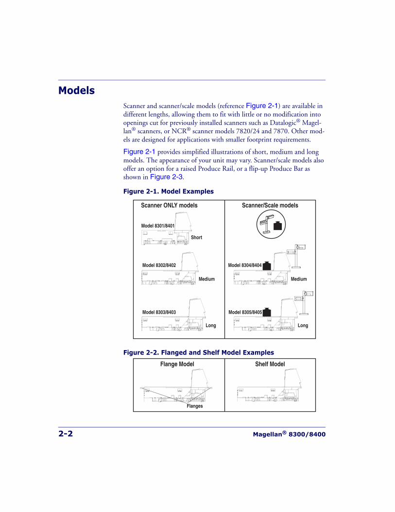
2-2 Magellan® 8300/8400
ModelsScanner and scanner/scale models (reference Figure 2-1) are available in different lengths, allowing them to fit with little or no modification into openings cut for previously installed scanners such as Datalogic® Magel-lan® scanners, or NCR® scanner models 7820/24 and 7870. Other mod-els are designed for applications with smaller footprint requirements.
Figure 2-1 provides simplified illustrations of short, medium and long models. The appearance of your unit may vary. Scanner/scale models also offer an option for a raised Produce Rail, or a flip-up Produce Bar as shown in Figure 2-3.
Figure 2-1. Model Examples
Figure 2-2. Flanged and Shelf Model Examples
Short
Medium
Long
Model 8301/8401
Model 8302/8402
Model 8303/8403
Scanner ONLY models Scanner/Scale models
Medium
Long
Model 8304/8404
Model 8305/8405
Flange Model Shelf Model
Flanges
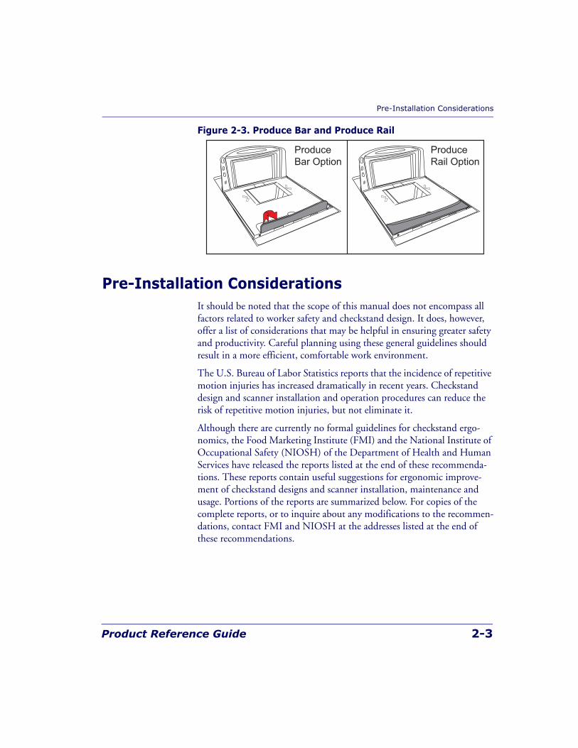
Pre-Installation Considerations
Product Reference Guide 2-3
Figure 2-3. Produce Bar and Produce Rail
Pre-Installation ConsiderationsIt should be noted that the scope of this manual does not encompass all factors related to worker safety and checkstand design. It does, however, offer a list of considerations that may be helpful in ensuring greater safety and productivity. Careful planning using these general guidelines should result in a more efficient, comfortable work environment.
The U.S. Bureau of Labor Statistics reports that the incidence of repetitive motion injuries has increased dramatically in recent years. Checkstand design and scanner installation and operation procedures can reduce the risk of repetitive motion injuries, but not eliminate it.
Although there are currently no formal guidelines for checkstand ergo-nomics, the Food Marketing Institute (FMI) and the National Institute of Occupational Safety (NIOSH) of the Department of Health and Human Services have released the reports listed at the end of these recommenda-tions. These reports contain useful suggestions for ergonomic improve-ment of checkstand designs and scanner installation, maintenance and usage. Portions of the reports are summarized below. For copies of the complete reports, or to inquire about any modifications to the recommen-dations, contact FMI and NIOSH at the addresses listed at the end of these recommendations.
ProduceBar Option
ProduceRail Option

2-4 Magellan® 8300/8400
Checkstand Design1. Select a design which allows load-sharing by several muscle groups
(for example designs which allow the cashier to use both hands for scanning and bagging).
2. Select checkstands which deliver products to the cashier on an input belt and do not require the unloading of items from a cart. These designs put less stress on the cashiers’ shoulders and back.
3. Minimize the distance between the input and take-away conveyors (i.e., the distance the cashier has to reach to move the products).
4. Minimize the width of the input conveyor to reduce the cashier’s reach to items on the far side of the belt; use a diverter to direct products closer to the cashier.
5. Select a design which encourages the cashier to slide products across the scanner rather than gripping and lifting. Make sure the horizon-tal surface of the scanner is flush with all surrounding surfaces.
6. Choose a design which integrates the scanner and scale to eliminate extended reaches and lifts during weighing tasks.
7. Provide an easily accessible bag stand at a height 13 - 17 inches (33 - 43.2 cm) lower than the top surface of the checkstand to reduce stresses to the shoulders, elbows, and risks associated with lifting products into bags.
8. Do not position the bag stand between the cashier and the scanner, due to the increased reach involved.
9. Position the scanner’s horizontal scanning surface 34 - 36 inches (86.4 - 91.4 cm) above the floor. Maintain a minimum of five inches (12.7 cm) clearance between elbows and work surfaces.
10. Provide adjustable keyboard mounting (height, tilt, and horizontal reach).
11. Position the printer, cash drawer, and other checkstand devices the cashier uses within easy reach (less than 18 inches/45.7 cm).
12. Provide adequate toe space, foot rests or rails, antifatigue mats, and where feasible, an adjustable seat or stand against which the cashiers can lean.
Scanner Installation
Product Reference Guide 2-5
Scanner Installation1. Mount the horizontal surface of the scanner flush with the counter-
top to encourage slide scanning rather than lifting.
2. Position the centerline of the scanner read area 8 - 10 inches (20.3 - 25.4 cm) from the edge of the checkstand (cashier side).
Scanner Maintenance1. Keep scanner windows clean. This will improve productivity and
reduce rescans.
2. Replace scanner glass when excessive scratches are evident.
ReferencesAnonymous, 1992, “Ergonomic Improvement of Scanning Checkstand Designs”, Food Marketing Institute800 Connecticut Ave. N.W.Washington, D.C. 20006
Grant, Katharyn A. et al., 1992, “Ergonomic Evaluation of Checkstand Designs in the Retail Food Industry”, National Institute of Occupational Safety and Health4676 Columbia ParkwayCincinnati, Ohio 45226
Scanner Usage1. Minimize handling of heavy/bulky products. Leave these items in
the cart and use an alternative entry method such as key entry of short PLUs, or handheld scanning.
2. Regularly train cashiers in proper scanning methods and ergonomics principles, such as:
2-6 Magellan® 8300/8400
• Develop a smooth fluid motion during scanning, sharing work equally between hands.
• Use the entire hand for grasping and lifting items.
• Since the scanner reads labels on all four sides plus the top and bottom, there is no need to turn a bar code toward either of the scanner windows.
• Develop efficient scanning motions, not necessarily faster hand movements. Simply slide the item across the scanner’s horizontal window with as little orientation motion as necessary.
• Leave items in an upright position; do not lift and tilt.
• Learn how the scanner functions and where the scanning area is located.
• Do not favor either the vertical or horizontal window; slide items across the scanner in their natural orientations on the checkstand as much as possible.
Site Preparation OverviewConsider the following factors before installing the scanner or scanner/scale and its optional Remote Scale Display.
Ventilation Requirements — The scanner operates without the use of a ventilation fan. As long as there is adequate convective air flow and no major heat producing equipment in close proximity, the unit’s housing provides adequate heat dissipation. The air temperature in the checkstand around the scanner must not exceed 104°F (40°C).
Service Access Requirements — Routine operations such as ‘zero-ing’ and calibration do not require removal of the scanner from the check-stand or disassembly of the product. The installer should plan service access for the AC/DC Power Supply and cables.
Site Preparation Overview
Product Reference Guide 2-7
Recommended Power Installation — Since the typical grocery envi-ronment includes conveyor belts and electric motors, care should be taken to ensure that the scanner has a supply of “clean” power (power without excessive electrical noise). A wiring diagram shows the recommended wir-ing that will provide the scanner with a “clean” source of power. Refer to Figure 2-6.
Counter Preparation — Since the majority of grocery checkout lanes are designed as “left-hand take away,” the counter drawings in this chapter focus on this counter design. Simply reverse the layout for a “right-hand take away” requirement. The unit scans equally well in either of these two configurations.
Liquid Drainage — Should a liquid spill occur, ensure that moisture can flow through the checkstand without pooling.
Leveling — Plan ahead and provide screws/bolts in the checkstand mounts and a leveling guide (board) to allow leveling of the scanner or scanner/scale within the counter. Use a 0.375” thick board to replicate the mounting flange on the long scanner or scanner/scale, and adjust screws or bolts until the board is flush within the counter. Use a 4.0” wide board stood on its end to adjust leveling screws/bolts in rail support applications.
Cable Routing — Placement of the scanner/scale should be planned to allow easy access to other components as well as optimize communication between the scanner, the POS terminal, the optional Remote Scale Dis-play and any EAS peripheral equipment. Do not route interface cables near any electrical motors or other sources of electromagnetic interference.
Remote Scale Display Placement — The customer, and checker in some instances, must be able to easily view and read the Remote Scale Dis-play. Ambient light and mounting height considerations are discussed later in this chapter.
Vertical Clearance — Provision must be made to allow adequate space above the scanner bonnet for removal and replacement of an L-shaped platter. Optimal clearance permits the platter to be grasped at its top verti-cal edge and lifted for removal without obstruction (such as a fixed key-board mount or any type of enclosure). Should such an enclosure be
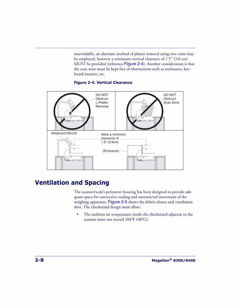
2-8 Magellan® 8300/8400
unavoidable, an alternate method of platter removal using two coins may be employed, however a minimum vertical clearance of 1.5” (3.8 cm) MUST be provided (reference Figure 2-4). Another consideration is that the scan zone must be kept free of obstructions such as enclosures, key-board mounts, etc.
Figure 2-4. Vertical Clearance
Ventilation and SpacingThe scanner/scale’s perimeter housing has been designed to provide ade-quate space for convective cooling and unrestricted movement of the weighing apparatus. Figure 2-5 shows the debris chutes and ventilation slots. The checkstand design must allow:
• The ambient air temperature inside the checkstand adjacent to the scanner must not exceed 104°F (40°C).
DO NOTObstructScan Zone
DO NOTObstructL-PlatterRemoval
Allow a minimumclearance of1.5" (3.8cm)
(Enclosure)
(Keyboard Mount)
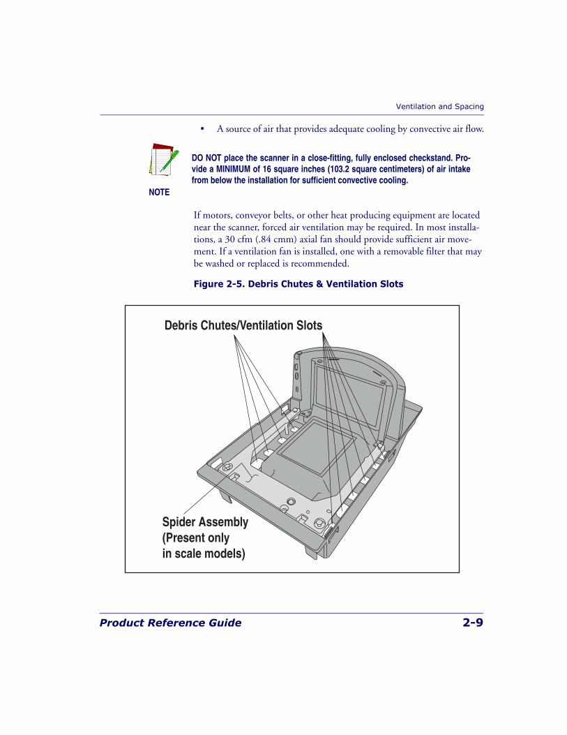
Ventilation and Spacing
Product Reference Guide 2-9
• A source of air that provides adequate cooling by convective air flow.
If motors, conveyor belts, or other heat producing equipment are located near the scanner, forced air ventilation may be required. In most installa-tions, a 30 cfm (.84 cmm) axial fan should provide sufficient air move-ment. If a ventilation fan is installed, one with a removable filter that may be washed or replaced is recommended.
Figure 2-5. Debris Chutes & Ventilation Slots
NOTE
DO NOT place the scanner in a close-fitting, fully enclosed checkstand. Pro-vide a MINIMUM of 16 square inches (103.2 square centimeters) of air intakefrom below the installation for sufficient convective cooling.
Debris Chutes/Ventilation Slots
Spider Assembly(Present onlyin scale models)
2-10 Magellan® 8300/8400
Service AccessThe scanner and scanner/scale have been engineered to allow performance of all routine service and maintenance (such as “zeroing” and calibration) without removing the scanner from the checkstand. Additionally all cable connections made at the scanner can be connected and removed while the unit is sitting on the countertop. The installer should provide service access to all remaining cable connectors as well as the AC/DC Power Sup-ply (if installed).
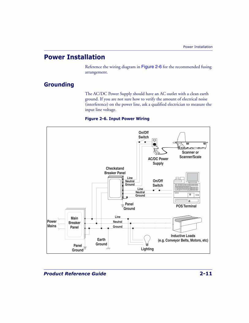
Power Installation
Product Reference Guide 2-11
Power InstallationReference the wiring diagram in Figure 2-6 for the recommended fusing arrangement.
GroundingThe AC/DC Power Supply should have an AC outlet with a clean earth ground. If you are not sure how to verify the amount of electrical noise (interference) on the power line, ask a qualified electrician to measure the input line voltage.
Figure 2-6. Input Power Wiring
AC/DC PowerSupply
PowerMains
Line
Neutral
Ground
EarthGround
PanelGround
PanelGround
MainBreakerPanel
CheckstandBreaker Panel
LineNeutralGround
LineNeutralGround
Lighting
Inductive Loads(e.g. Conveyor Belts, Motors, etc)
Scanner orScanner/Scale
POS Terminal
On/OffSwitch
On/OffSwitch
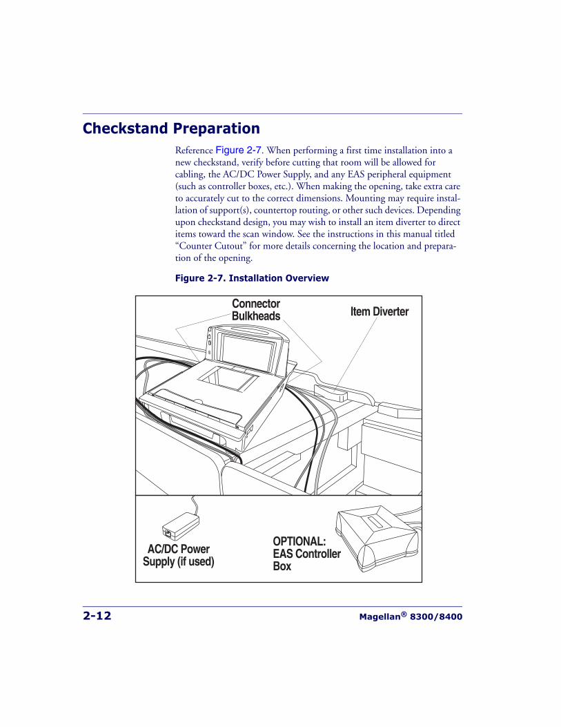
2-12 Magellan® 8300/8400
Checkstand PreparationReference Figure 2-7. When performing a first time installation into a new checkstand, verify before cutting that room will be allowed for cabling, the AC/DC Power Supply, and any EAS peripheral equipment (such as controller boxes, etc.). When making the opening, take extra care to accurately cut to the correct dimensions. Mounting may require instal-lation of support(s), countertop routing, or other such devices. Depending upon checkstand design, you may wish to install an item diverter to direct items toward the scan window. See the instructions in this manual titled “Counter Cutout” for more details concerning the location and prepara-tion of the opening.
Figure 2-7. Installation Overview
Item DiverterConnectorBulkheads
AC/DC PowerSupply (if used)
OPTIONAL:EAS ControllerBox
Counter Cutout
Product Reference Guide 2-13
Liquid Spills and Moisture Select a checkstand design which allows fluids to flow through, and directs liquids away from any electronic equipment or storage areas.
Counter CutoutThe most important consideration when planning the counter opening for the scanner is the operator’s comfortable reaching distance. The ideal, ergonomically sound installation allows items to be directed within easy reach, and a scanning area requiring no lifting or special orientation of items. If you haven’t already read the information at the beginning of this chapter titled, Pre-Installation Considerations, please do so before continuing these instructions.
The symmetrical design of the scanner permits the operator to easily pass items from one hand to the other while scanning (either from right-to-left or left-to-right). With the unique 360- scan zone, scanning is accom-plished in one fluid motion. The operator simply slides the item from the conveyor belt or diverter area through the scanning area and passes the item to the other hand, which in turn bags it or places it on a take-away conveyor belt. Movement should flow naturally over the surface of the scanner.
Note that the following guidelines for preparing an existing checkstand to accept a scanner, or incorporating the unit into a new checkstand design will not be accurate for all installations. Although these guidelines will suf-fice for most standard installations, the installer may need to make adjust-ments for varying counter heights and thicknesses, support design, or other checkstand limitations.
Figure 2-8 shows a typical “left-hand-take-away” checkstand design.
Follow these basic steps to install the unit:
1. Select a position for the scanner that offers a smooth product flow which best accommodates the reaching distance of the average oper-ator.
2. Cut the opening in the countertop. Reference Table 2-1 to find the cut-out dimensions for your model. Flange and shelf mount dimen-sions are provided for your convenience.
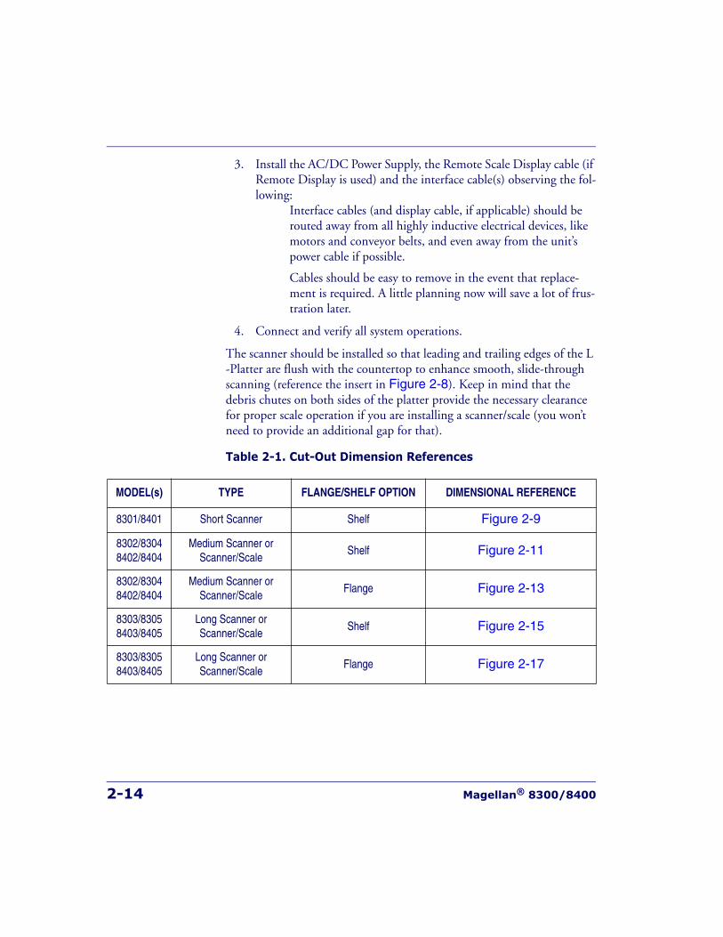
2-14 Magellan® 8300/8400
3. Install the AC/DC Power Supply, the Remote Scale Display cable (if Remote Display is used) and the interface cable(s) observing the fol-lowing:
Interface cables (and display cable, if applicable) should be routed away from all highly inductive electrical devices, like motors and conveyor belts, and even away from the unit’s power cable if possible.
Cables should be easy to remove in the event that replace-ment is required. A little planning now will save a lot of frus-tration later.
4. Connect and verify all system operations.
The scanner should be installed so that leading and trailing edges of the L -Platter are flush with the countertop to enhance smooth, slide-through scanning (reference the insert in Figure 2-8). Keep in mind that the debris chutes on both sides of the platter provide the necessary clearance for proper scale operation if you are installing a scanner/scale (you won’t need to provide an additional gap for that).
Table 2-1. Cut-Out Dimension References
MODEL(s) TYPE FLANGE/SHELF OPTION DIMENSIONAL REFERENCE
8301/8401 Short Scanner Shelf Figure 2-9
8302/83048402/8404
Medium Scanner orScanner/Scale
Shelf Figure 2-11
8302/83048402/8404
Medium Scanner orScanner/Scale
Flange Figure 2-13
8303/83058403/8405
Long Scanner orScanner/Scale
Shelf Figure 2-15
8303/83058403/8405
Long Scanner orScanner/Scale
Flange Figure 2-17
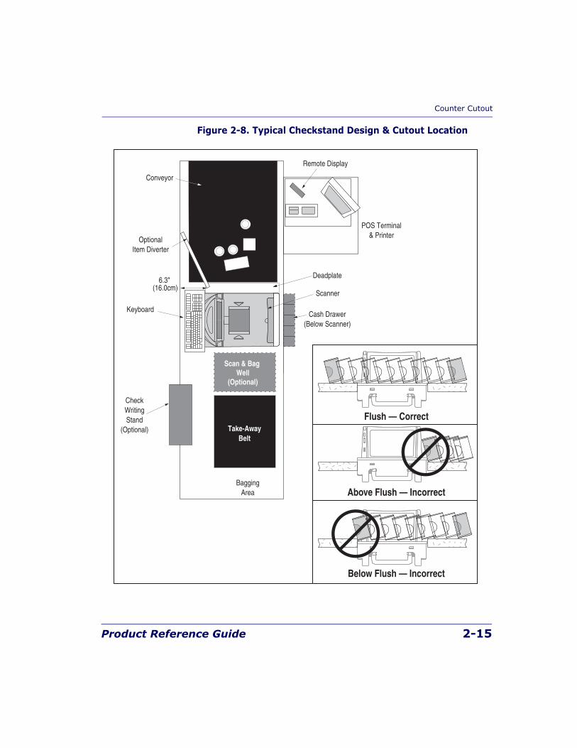
Counter Cutout
Product Reference Guide 2-15
Figure 2-8. Typical Checkstand Design & Cutout Location
OptionalItem Diverter
Conveyor
Deadplate
Scanner
BaggingArea
Take-AwayBelt
Keyboard
Remote Display
POS Terminal& Printer
CheckWritingStand
(Optional)
Scan & Bag Well
(Optional)
6.3"(16.0cm)
Cash Drawer(Below Scanner)
Flush — Correct
Above Flush — Incorrect
Below Flush — Incorrect
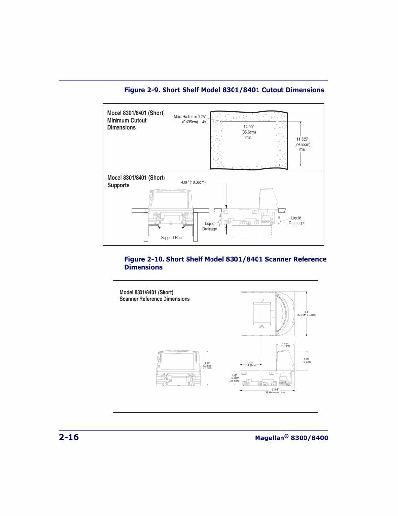
2-16 Magellan® 8300/8400
Figure 2-9. Short Shelf Model 8301/8401 Cutout Dimensions
Figure 2-10. Short Shelf Model 8301/8401 Scanner Reference Dimensions
11.625"(29.53cm)
min.
Model 8301/8401 (Short)Minimum CutoutDimensions
Model 8301/8401 (Short)Supports
Max. Radius = 0.25"(0.635cm) 4x
4.08" (10.36cm)
LiquidDrainageLiquid
Drainage
Support Rails
14.00"(35.6cm)
min.
Model 8301/8401 (Short)Scanner Reference Dimensions
4.59"(11.7cm)
4.08"(10.36cm± 0.15cm)
5.6"(14.22cm)
13.85"(35.19cm ± 0.15cm)
11.5"(29.21cm ± 0.1cm)
5.19"(13.2cm)9.27"
(23.6cm± 0.2cm)
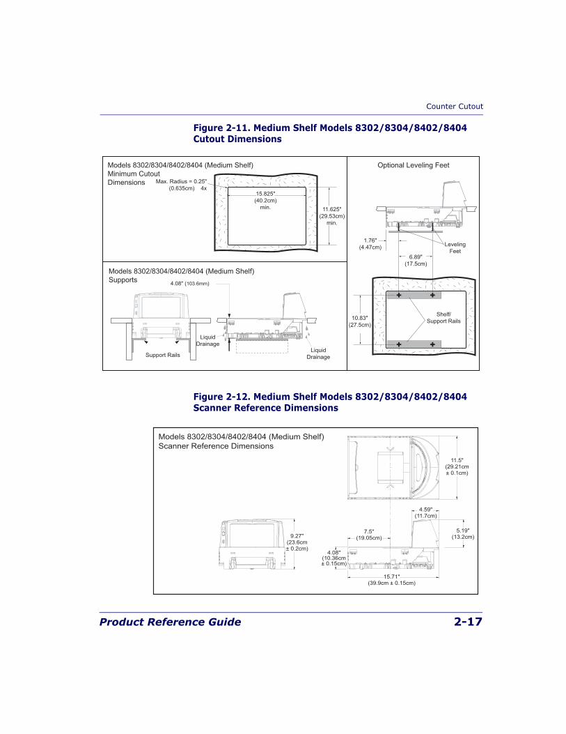
Counter Cutout
Product Reference Guide 2-17
Figure 2-11. Medium Shelf Models 8302/8304/8402/8404 Cutout Dimensions
Figure 2-12. Medium Shelf Models 8302/8304/8402/8404 Scanner Reference Dimensions
Models 8302/8304/8402/8404 (Medium Shelf)Minimum CutoutDimensions
Optional Leveling Feet
11.625"(29.53cm)
min.
Max. Radius = 0.25"(0.635cm) 4x
15.825"(40.2cm)
min.
Models 8302/8304/8402/8404 (Medium Shelf)Supports 4.08" (103.6mm)
LiquidDrainage
LiquidDrainage
Support Rails
6.89"(17.5cm)
1.76"(4.47cm)
10.83"(27.5cm)
Shelf/Support Rails
LevelingFeet
Models 8302/8304/8402/8404 (Medium Shelf)Scanner Reference Dimensions
7.5"(19.05cm)
4.08"(10.36cm± 0.15cm)
15.71"(39.9cm ± 0.15cm)
4.59"(11.7cm)
11.5"(29.21cm± 0.1cm)
5.19"(13.2cm)9.27"
(23.6cm± 0.2cm)
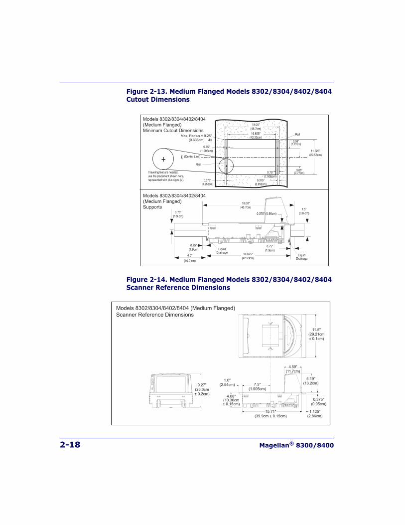
2-18 Magellan® 8300/8400
Figure 2-13. Medium Flanged Models 8302/8304/8402/8404 Cutout Dimensions
Figure 2-14. Medium Flanged Models 8302/8304/8402/8404 Scanner Reference Dimensions
Models 8302/8304/8402/8404(Medium Flanged)Minimum Cutout Dimensions
Models 8302/8304/8402/8404(Medium Flanged)Supports
18.00"(45.7cm)
16.625"(42.23cm)
0.75"(1.9 cm)
1.5"(3.8 cm)
0.75"(1.9cm)
0.75"(1.9cm)
4.0"
(10.2 cm)
0.375" (0.95cm)
LiquidDrainage
LiquidDrainage
18.00"(45.7cm)16.625"
(42.23cm)Max. Radius = 0.25"(0.635cm) 4x
0.75"(1.905cm)
Rail
Rail
(Center Line)
0.75"(1.905cm)
0.375"(0.952cm)
0.375"(0.952cm)
If leveling feet are needed,use the placement shown here,represented with plus signs (+).
3.06"(7.77cm)
3.06"(7.77cm)
11.625"(29.53cm)
Models 8302/8304/8402/8404 (Medium Flanged)Scanner Reference Dimensions
7.5"(1.905cm)
1.0"(2.54cm)
4.08"(10.36cm± 0.15cm)
15.71"(39.9cm ± 0.15cm)
1.125"(2.86cm)
0.375"(0.95cm)
4.59"(11.7cm)
11.5"(29.21cm± 0.1cm)
5.19"(13.2cm)9.27"
(23.6cm± 0.2cm)
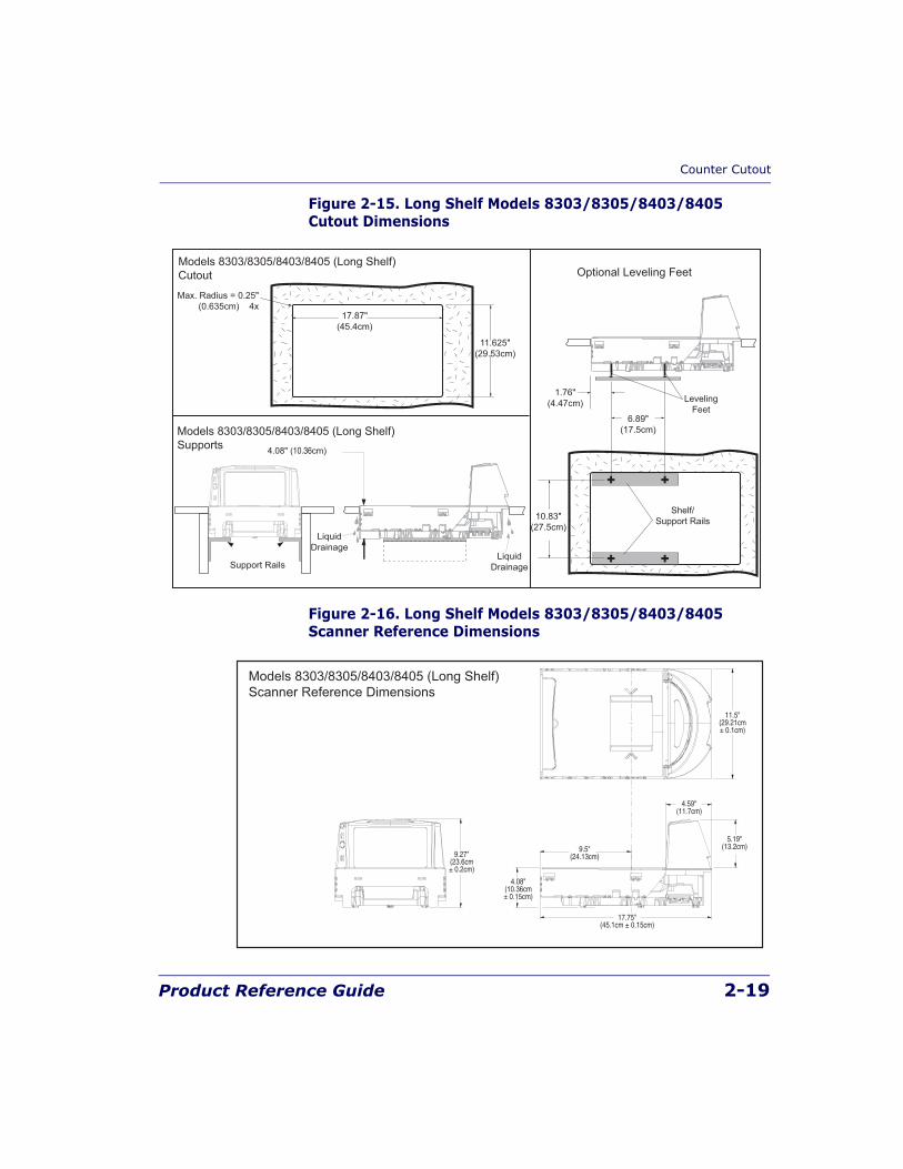
Counter Cutout
Product Reference Guide 2-19
Figure 2-15. Long Shelf Models 8303/8305/8403/8405 Cutout Dimensions
Figure 2-16. Long Shelf Models 8303/8305/8403/8405 Scanner Reference Dimensions
Models 8303/8305/8403/8405 (Long Shelf)Cutout
11.625"(29.53cm)
Max. Radius = 0.25"(0.635cm) 4x
17.87"(45.4cm)
Models 8303/8305/8403/8405 (Long Shelf)Supports 4.08" (10.36cm)
LiquidDrainage
LiquidDrainage
Support Rails
Optional Leveling Feet
6.89"(17.5cm)
1.76"(4.47cm)
10.83"(27.5cm)
Shelf/Support Rails
LevelingFeet
Models 8303/8305/8403/8405 (Long Shelf)Scanner Reference Dimensions
9.27"(23.6cm± 0.2cm)
9.5"(24.13cm)
17.75"(45.1cm ± 0.15cm)
4.59"(11.7cm)
11.5"(29.21cm± 0.1cm)
5.19"(13.2cm)
4.08"(10.36cm± 0.15cm)
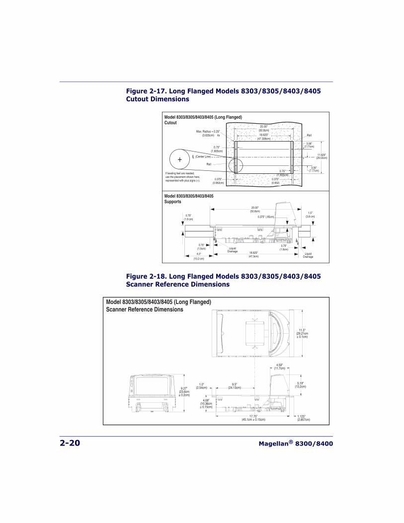
2-20 Magellan® 8300/8400
Figure 2-17. Long Flanged Models 8303/8305/8403/8405 Cutout Dimensions
Figure 2-18. Long Flanged Models 8303/8305/8403/8405 Scanner Reference Dimensions
Model 8303/8305/8403/8405 (Long Flanged)Cutout
Model 8303/8305/8403/8405Supports
20.00"(50.8cm)
0.75"(1.905cm)
18.625"(47.308cm)
Rail
Rail
(Center Line) 11.625"(29.53cm)
0.75"(1.905cm)
Max. Radius = 0.25"(0.635cm) 4x
20.00"(50.8cm)
18.625"(47.3cm)
0.375"(0.952cm)
0.375"(0.952)
If leveling feet are needed,use the placement shown here,represented with plus signs (+).
3.06"(7.77cm)
3.06"(7.77cm)
0.75"(1.9 cm)
1.5"(3.8 cm)
0.75"(1.9cm)
0.75"(1.9cm)
4.0"
(10.2 cm)
LiquidDrainage
LiquidDrainage
0.375" (.95cm)
Model 8303/8305/8403/8405 (Long Flanged)Scanner Reference Dimensions
1.0"(2.54cm)
9.5"(24.13cm)
1.125"(2.857cm)
11.5"(29.21cm± 0.1cm)
4.59"(11.7cm)
5.19"(13.2cm)
17.75"(45.1cm ± 0.15cm)
4.08"(10.36cm± 0.15cm)
9.27"(23.6cm± 0.2cm)
Installation Overview
Product Reference Guide 2-21
Checkstand MountingThere are a number of things to take into account when installing the unit into a checkstand. Key factors are ergonomic/worker safety, loading capac-ity and stability. Consider the scanner or scanner/scale’s weight when cal-culating the robustness of construction needed to support it as well as maximum capacity of weighed and scanned items.
Checkstand VibrationProper function of the scanner/scale is dependent upon an installation which minimizes excess vibration from conveyor belts, fans, and other such equipment. See Chapter 4, Scale Error Reporting, if vibration is suspected of causing operational problems.
Installation OverviewThe preceding Site Preparation Overview dealt with installed location and counter preparations to accommodate the scanner or scanner/scale. Having completed those steps, physical installation of the scanner or scan-ner/scale can begin. The following instructions apply to all models.
This chapter describes:
1. Unpacking the unit.
2. Verifying operation before connecting to a POS system.
3. Routing and connecting cables.
4. Validating that your scanner communication parameters match the POS terminal’s system requirements.
5. Confirming connection to the (optional) EAS system.
NOTE
If you choose to rout a countertop with a thickness of 0.75” (1.9 cm) plywood,you’ll need to add a backing strip that supports the area routed out for thesupport flanges (see Figure 2-7). This support strip should minimally bemade of 0.75” (1.9 cm) thick plywood and be approximately 4.0” (10.2 cm)wide and 14.0” (35.6 cm) long. This strip should be glued as well as screwedto the underside of the countertop.
2-22 Magellan® 8300/8400
6. Functional testing to verify operation when connected to the POS system.
The following text describes each of these steps.
UnpackingTo unpack the unit:
• Inspect the package for signs of damage that may have occurred dur-ing shipping. If damage is found, report it to your carrier immedi-ately.
• Lift out the accessory box containing the AC/DC Power Supply, optional Remote Scale Display and cable (if present), and the Quick Reference Guide.
• Remove the Quick Reference Guide and familiarize yourself with the unit’s controls and features. Leave the guide at the checkstand when the installation is complete.
• Remove the protective packing and carefully lift the unit from the carton. Be sure to save the box and all packing material. In the event of failure, the unit must be returned to the factory in its original packaging.
• Carefully lift off the L-Platter as shown in Figure 2-27 and remove the protective foam pieces securing the weigh mechanism. Set the platter back in place.
NOTE
For added protection during shipment, the L-Platter is covered with a tight-fitting layer of vinyl as shown in Figure 2-19. This vinyl layer MUST BEREMOVED before placing the unit into service.
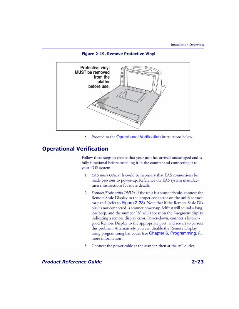
Installation Overview
Product Reference Guide 2-23
Figure 2-19. Remove Protective Vinyl
• Proceed to the Operational Verification instructions below.
Operational VerificationFollow these steps to ensure that your unit has arrived undamaged and is fully functional before installing it in the counter and connecting it to your POS system.
1. EAS units ONLY: It could be necessary that EAS connections be made previous to power-up. Reference the EAS system manufac-turer’s instructions for more details.
2. Scanner/Scale units ONLY: If the unit is a scanner/scale, connect the Remote Scale Display to the proper connector on the unit’s connec-tor panel (refer to Figure 2-23). Note that if the Remote Scale Dis-play is not connected, a scanner power-up Selftest will sound a long, low beep, and the number “8” will appear on the 7-segment display indicating a remote display error. Power-down, connect a known-good Remote Display to the appropriate port, and restart to correct this problem. Alternatively, you can disable the Remote Display using programming bar codes (see Chapter 6, Programming, for more information).
3. Connect the power cable at the scanner, then at the AC outlet.
Protective vinylMUST be removed
from theplatter
before use.
2-24 Magellan® 8300/8400
When power is applied to the unit, the normal indicator sequence is:
• The scanner indicator (top-most, green LED) will be lit (dim) steadily.
• The 7-segment display will flash the number ‘8’. indicating initial-ization.
• If the Selftest detects a problem, the 7-segment display will display a number code. Refer to Chapter 4, Problem Isolation, for a description of failure codes and problem isolation procedures.
4. The unit should be permitted to reach thermal equilibrium before proceeding to the next steps. (Reference the topic Warm-Up Timein Chapter 1, Introduction.) When the unit is moved from a cooler temperature (such as a storage area) to a warmer environment (such as a checkstand location), a period of 60 minutes must be allowed to acclimate the unit to ambient conditions. Once installed and powered up, a “power-up” warm-up period of 15 minutes must be allowed before calibrating or performing weighing operations. These two warm-up periods may run concurrently.
5. Verify that the scanner or scanner/scale passes an operational test by observing the following:
NOTE
Scale calibration may be necessary to obtain a zero reading on the display onrare occasions.
Installation Overview
Product Reference Guide 2-25
Scanner — Pass UPC/EAN bar code labels in front of the scanner’s win-dows. Since the interface cable is not yet connected to the POS ter-minal, the scanner may be limited to reading only one or two labels (see the note that follows). The scanner indicates when each label has been successfully read by flashing the green scanner light and emitting a good read tone (beep). Some host interface types may “chirp” instead of beeping.
EAS System — The way in which EAS labels are deactivated is depen-dent upon which aftermarket EAS system was purchased and installed. See the user’s manuals and other documentation accompanying that EAS equipment.
Scale — If the Yellow (bottom) LED/Button is not lit, press that button momentarily. If the scale is operating correctly, the yellow LED will illuminate and remain on steady, and the display will show a reading of 0.00 lb (0.000 kg for metric). If the display is blank or a
is displayed, it may be necessary to calibrate the scale before continuing. Refer to Chapter 5, Calibration, for calibra-tion procedures.
Remote Scale Display — Check to verify that 0.00 lb (0.000 kg for metric) is displayed, then place an item on the weighing platter. Ver-ify that the display shows a weight and that the yellow LED goes out. Remove the item and observe that Remote Scale Display shows 0.00 lb (0.000 kg for metric) and that the yellow LED is On.
6. Unplug the AC power cord from the outlet and disconnect the power cord and Remote Scale Display cable from the scanner’s con-nector panel.
After you have verified that the scanner, EAS system and scale (if present) are completely functional, continue with the following procedures to complete the installation.
NOTE
When not connected to the host, the scanner may be limited to reading onlyone or two labels. (This limitation is dependent upon the interface type.) Toscan multiple labels without connecting to the host, place the unit in ScannerDiagnostic Mode by pressing the Volume/Tone Push Button for four seconds.
- 0 -
2-26 Magellan® 8300/8400
Diagnostic ModesTwo diagnostic modes are available which allow you to initiate scanner or scale diagnostic tests, as well as verify the scanner’s ability to read bar codes.
Scanner Diagnostic Mode
While in Scanner Diagnostic Mode, continuous scanning of labels is allowed, permitting the user to scan an unlimited number of bar codes while troubleshooting problems. Under normal operation, the scanner stores label data, awaiting the signal which transmits it to the host. When the scanner is not connected to a host, it may read and store only up to two labels, then quit reading until power is cycled (clearing the memory). This mode of operation removes this limitation.
To place the scanner in Scanner Diagnostic Mode, press the Volume/Tone (top) Push Button for approximately four seconds. While pressing the button, the scanner will first sound three tones, wait a few seconds, then sound six rapid tones; after which you should immediately release the but-ton.
While in Scanner Diagnostic Mode, identification numbers for interface1
type, firmware and configuration will scroll continually across the scan-ner’s 7-segment FRU (Field Replaceable Unit) display. This is useful infor-mation for field diagnostics. See Figure 4-1 for the location of the display. For example, if the dual cable RS-232 interface (type 05) were enabled, the firmware designation was R96-1234, and the configuration was R96-5593, the following would be shown (slowly, with blanking between each of the items):
IF-05 r96-1234 r96-5593.
To exit Scanner Diagnostic Mode, cycle power to the unit or press and hold the Volume/Tone Push Button for eight seconds to reset the scanner. See Chapter 3, Scanner and Scale Reset for more information about unit resets.
1. A listing of scanner interface identification numbers is available in Chapter 6, Programming,
under the topic, Interface Type.
Installation Overview
Product Reference Guide 2-27
Scale Diagnostic Mode
To enter Scale Diagnostic Mode, press the Scale Zero Push Button for approximately four seconds. Six rapid tones will be sounded, indicating the unit is leaving normal operation and entering Scale Diagnostic Mode. The Remote Display will flash a ‘1’ across the display while the dignostic routine is being run. When diagnostics are completed successfully, the dis-play will indicate that the unit has passed the diagnostic test by displaying
. Next, the display shows a listing of how many times the unit has been calibrated and zeroed in the form of: where x equals the number of times the scale has been calibrated. Next, the unit will dis-play where x is the number of times the scale has been zeroed. Finally, all segments will be displayed in the form of: to allow visual verification of display function.If the diagnostics routine is not completed successfully, the scanner will sound a series of tones and the Remote Display will show an error code. Turn to Chapter 4, Problem Isolation, for a description of error codes.
Press the Scale Zero Push Button once more to reset the unit and exit Scale Diagnostic Mode. See Chapter 3, Scanner and Scale Reset for more information about unit resets.
Cables & ConnectionsConsiderations when routing the power and interface cables for the scan-ner and scanner/scale are:
• Ensure that cables are not pinched, kinked or pierced.
• Do not route interface cables in close proximity to electrical motors or other sources of electromagnetic interference.
Do not plug the AC power cord into the outlet at this time. It is a good practice to always connect the power cable to the scanner first before plug-ging it into the AC receptacle. The procedures titled, Set-Up, provided later in this chapter will instruct you to connect the power cord at that time. Figure 2-20 illustrates the basic cable routing scheme.
PASS
c XXX
Zero XXXX
-18.8.88
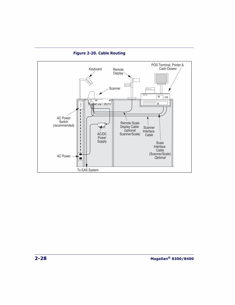
2-28 Magellan® 8300/8400
Figure 2-20. Cable Routing
Scanner
AC PowerSwitch
(recommended)
AC/DCPowerSupply
AC Power
To EAS System
ScannerInterface
Cable
ScaleInterface
Cable(Scanner/Scale)
Optional
Remote ScaleDisplay Cable
(optionalScanner/Scale)
POS Terminal, Printer & Cash DrawerRemote
DisplayKeyboard
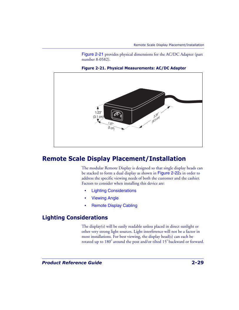
Remote Scale Display Placement/Installation
Product Reference Guide 2-29
Figure 2-21 provides physical dimensions for the AC/DC Adapter (part number 8-0582).
Figure 2-21. Physical Measurements: AC/DC Adapter
Remote Scale Display Placement/InstallationThe modular Remote Display is designed so that single display heads can be stacked to form a dual display as shown in Figure 2-22a in order to address the specific viewing needs of both the customer and the cashier. Factors to consider when installing this device are:
• Lighting Considerations
• Viewing Angle
• Remote Display Cabling
Lighting ConsiderationsThe display(s) will be easily readable unless placed in direct sunlight or other very strong light sources. Light interference will not be a factor in most installations. For best viewing, the display head(s) can each be rotated up to 180º around the post and/or tilted 15º backward or forward.
3.35"
(8.5 cm)
1.97"(5 cm)
1.23"(3.1 cm)
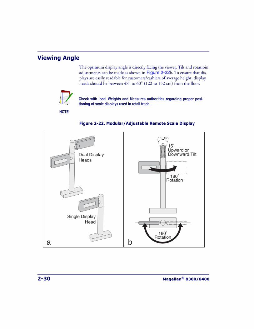
2-30 Magellan® 8300/8400
Viewing AngleThe optimum display angle is directly facing the viewer. Tilt and rotatioin adjustments can be made as shown in Figure 2-22b. To ensure that dis-plays are easily readable for customers/cashiers of average height, display heads should be between 48” to 60” (122 to 152 cm) from the floor.
Figure 2-22. Modular/Adjustable Remote Scale Display
NOTE
Check with local Weights and Measures authorities regarding proper posi-tioning of scale displays used in retail trade.
180˚Rotation
15˚Upward orDownward Tilt
180˚Rotation
15˚ 15˚
Dual DisplayHeads
Single DisplayHead
a b
Remote Scale Display Placement/Installation
Product Reference Guide 2-31
Remote Display CablingYour installation should also take into account the routing of Remote Dis-play cabling. Ensure that distance and obstacles spanned by the routed cable will not kink, pinch or stretch it. Also keep in mind you may need to drill a hole through which to route it.
Placing and Installing the Remote Scale DisplayReference Figure 2-24 while performing these procedures.
1. Determine where you want to install the Remote Scale Display based on your counter design, the viewing angle, lighting consider-ations and cable routing discussed previously. Reference Figure 2-22 for the display’s physical dimensions. Optimally, the display(s) should be approximately eye level to the viewer(s).
2. Use the template provided in Figure 2-25 to mark locations of the mounting screw and cable routing holes. The mounting screw holes are on 3-1/2” (85.1 mm) centers. The cable can either be routed through a 3/4” (19 mm) diameter hole directly under the mounting base or through the cutout in the back of the base (see Figure 2-24).
3. Drill the mounting screw holes using a drill bit of the appropriate diameter for your mounting screws or bolts.
4. Drill the cable routing hole using a 3/4” (19 mm) drill bit (optional).
NOTE
The Remote Scale Display connector end may be secured with a rubber bandduring shipping to prevent damage to the “locking tabs” (see Figure 2-24).After routing the cable, remove this rubber band before connecting. Failure toremove the band will keep the connector from latching properly.
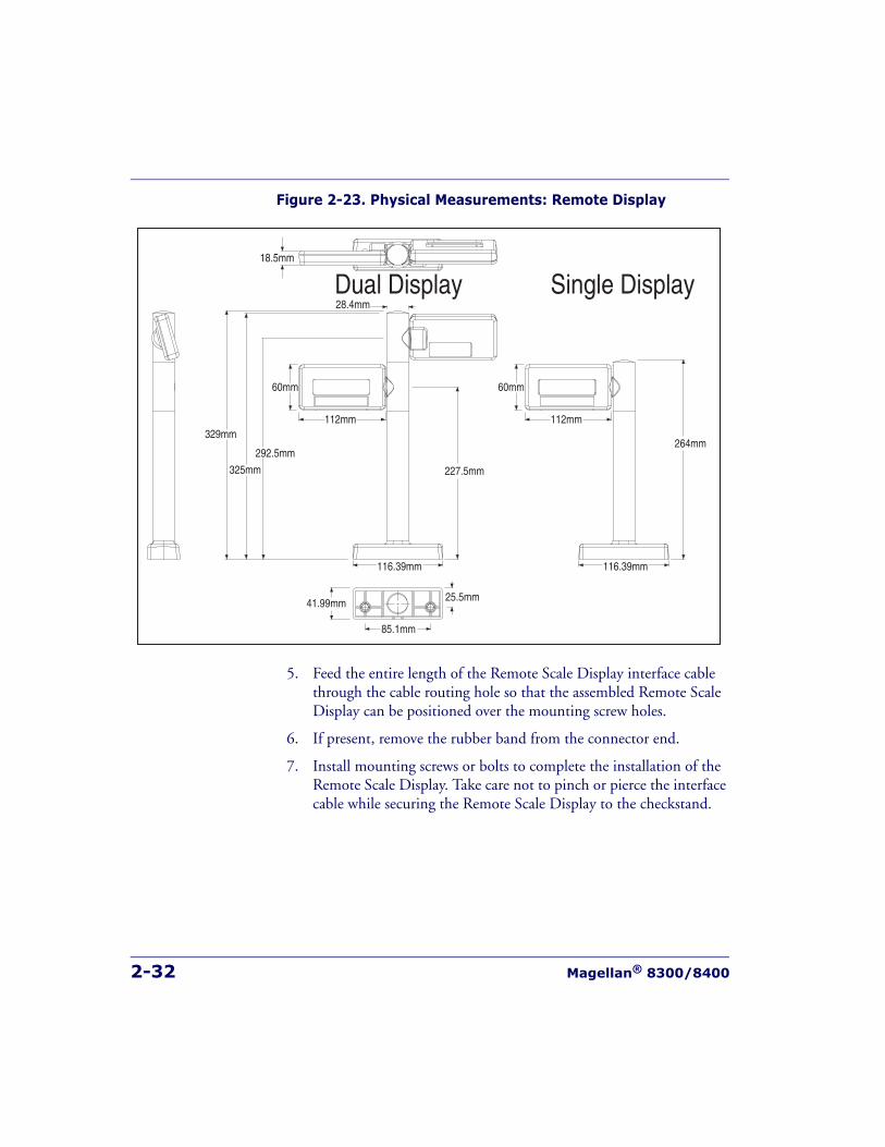
2-32 Magellan® 8300/8400
Figure 2-23. Physical Measurements: Remote Display
5. Feed the entire length of the Remote Scale Display interface cable through the cable routing hole so that the assembled Remote Scale Display can be positioned over the mounting screw holes.
6. If present, remove the rubber band from the connector end.
7. Install mounting screws or bolts to complete the installation of the Remote Scale Display. Take care not to pinch or pierce the interface cable while securing the Remote Scale Display to the checkstand.
18.5mm
28.4mmDual Display Single Display
329mm
325mm
292.5mm
227.5mm
116.39mm
112mm
60mm
264mm
116.39mm
112mm
60mm
25.5mm
85.1mm
41.99mm
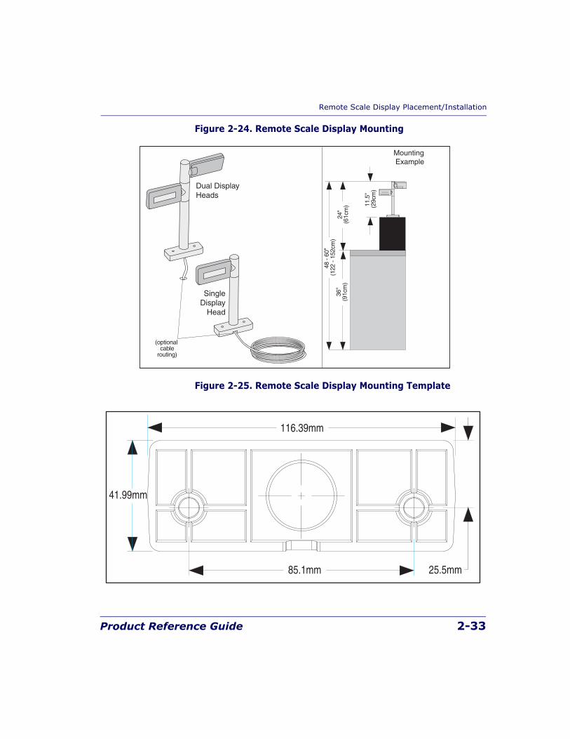
Remote Scale Display Placement/Installation
Product Reference Guide 2-33
Figure 2-24. Remote Scale Display Mounting
Figure 2-25. Remote Scale Display Mounting Template
48 -
60"
(122
- 15
2cm
)36
"(9
1cm
)
11.5
" (2
9cm
)
24"
(61c
m)
MountingExample
(optionalcable
routing)
Dual DisplayHeads
SingleDisplay
Head
25.5mm85.1mm
116.39mm
41.99mm
2-34 Magellan® 8300/8400
Changing Weighing ModesYour scanner/scale has been programmed for weighing in either pounds or kilograms depending upon the initial operating environment that was specified when you ordered your scanner/scale. If you need to change from pounds to kilograms or vice-versa, call technical support.
You can verify that the scale is set correctly for your country’s requirements by observing that the Remote Scale Display shows the appropriate mea-surement symbol (lb or kg) when the power-up Selftest is completed.
Set-Up & InstallationThese setup and installation procedures assume that you have already pre-pared your checkstand to receive the scanner or scanner/scale. If you have not already made the counter cutout and routed power and interface cables, do so now as described in the previous instructions. If your check-stand has been prepared, proceed as follows:
Set-up1. Place the scanner on the checkstand next to the counter cutout.
2. Make all connections to peripheral devices, such as the Remote Scale Display (see Figure 2-24) and, if your installation includes an EAS system, refer to that manufacturer’s instructions for connection and start-up procedures.
3. Route the cables up through the cutout and connect the scanner and scale interface cable(s), EAS cable and Remote Scale Display cable (optional) to the scanner. Some POS terminals require two interface cables; one for the scanner interface and one for the scale interface. Refer to Figure 2-26 for cable connection locations.
Any time the scale weighing mode is changed, the scale must bere-calibrated before commercial use.
LEGAL NOTE
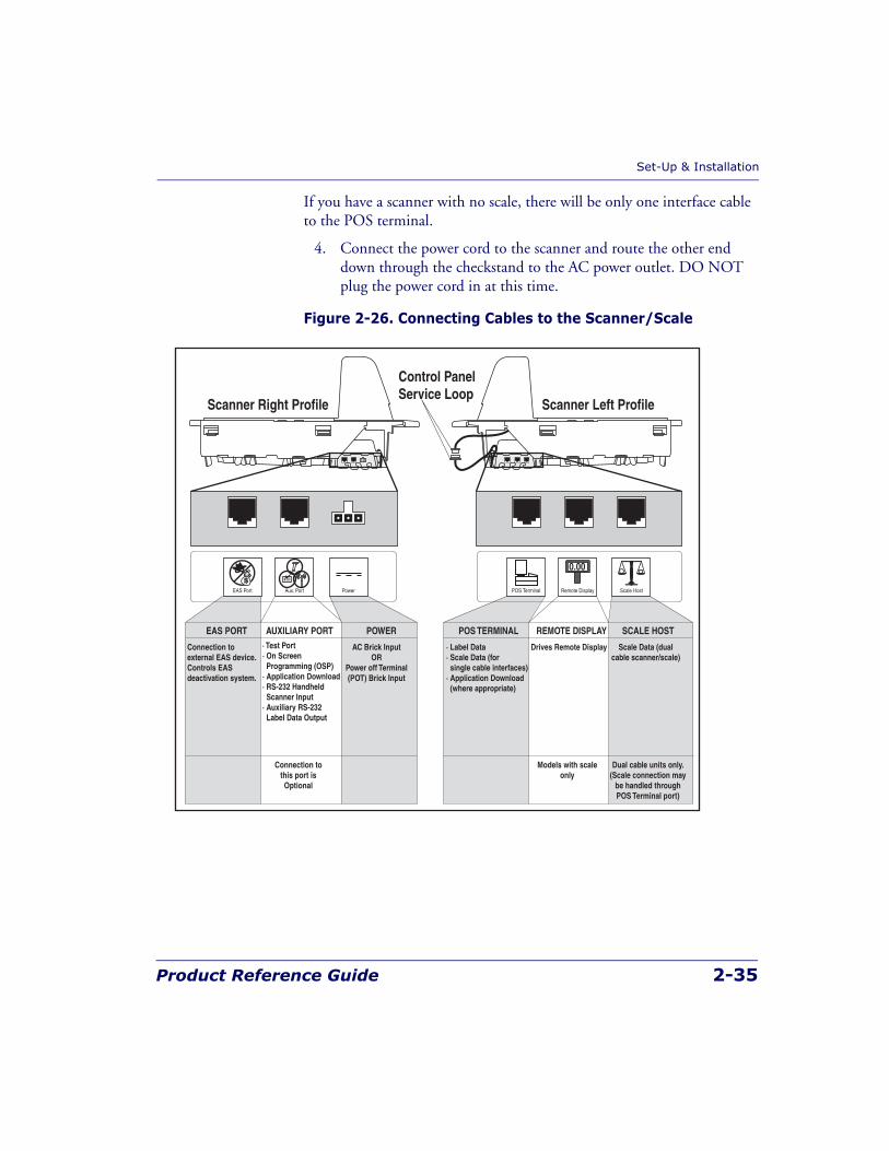
Set-Up & Installation
Product Reference Guide 2-35
If you have a scanner with no scale, there will be only one interface cable to the POS terminal.
4. Connect the power cord to the scanner and route the other end down through the checkstand to the AC power outlet. DO NOT plug the power cord in at this time.
Figure 2-26. Connecting Cables to the Scanner/Scale
POS TERMINAL REMOTE DISPLAYAUXILIARY PORT SCALE HOSTEAS PORT
Connection tothis port isOptional
Scale Data (dualcable scanner/scale)
Drives Remote Display· Label Data· Scale Data (forsingle cable interfaces)
· Application Download (where appropriate)
· Test Port· On Screen Programming (OSP)· Application Download· RS-232 Handheld Scanner Input· Auxiliary RS-232 Label Data Output
Models with scaleonly
Connection toexternal EAS device.Controls EASdeactivation system.
Dual cable units only.(Scale connection may
be handled throughPOS Terminal port)
POS Terminal Remote DisplayAux. PortEAS Port Scale Host
0.00
POWER
AC Brick InputOR
Power off Terminal(POT) Brick Input
Power
Control PanelService Loop
Scanner Right Profile Scanner Left Profile
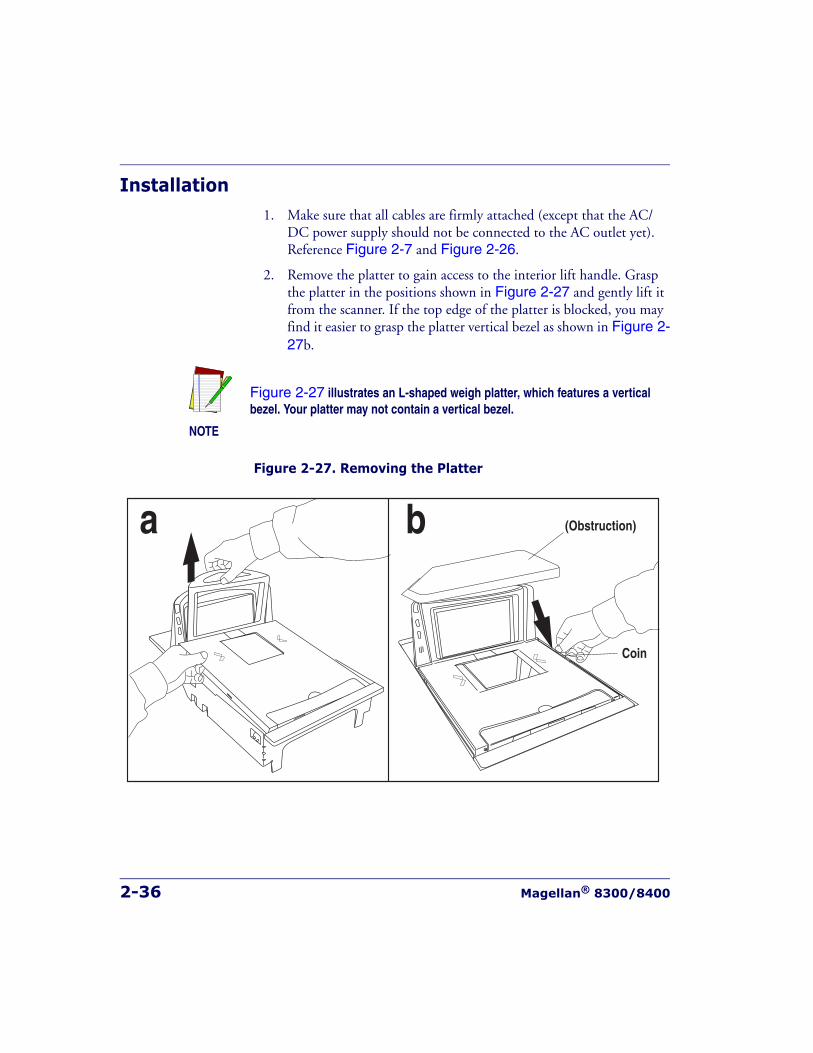
2-36 Magellan® 8300/8400
Installation1. Make sure that all cables are firmly attached (except that the AC/
DC power supply should not be connected to the AC outlet yet). Reference Figure 2-7 and Figure 2-26.
2. Remove the platter to gain access to the interior lift handle. Grasp the platter in the positions shown in Figure 2-27 and gently lift it from the scanner. If the top edge of the platter is blocked, you may find it easier to grasp the platter vertical bezel as shown in Figure 2-27b.
Figure 2-27. Removing the Platter
NOTE
Figure 2-27 illustrates an L-shaped weigh platter, which features a verticalbezel. Your platter may not contain a vertical bezel.
a b
Coin
(Obstruction)
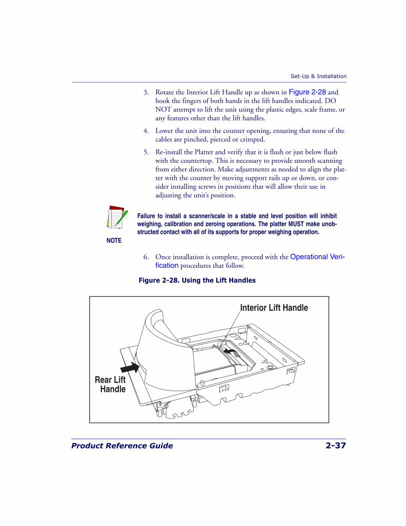
Set-Up & Installation
Product Reference Guide 2-37
3. Rotate the Interior Lift Handle up as shown in Figure 2-28 and hook the fingers of both hands in the lift handles indicated. DO NOT attempt to lift the unit using the plastic edges, scale frame, or any features other than the lift handles.
4. Lower the unit into the counter opening, ensuring that none of the cables are pinched, pierced or crimped.
5. Re-install the Platter and verify that it is flush or just below flush with the countertop. This is necessary to provide smooth scanning from either direction. Make adjustments as needed to align the plat-ter with the counter by moving support rails up or down, or con-sider installing screws in positions that will allow their use in adjusting the unit’s position.
6. Once installation is complete, proceed with the Operational Veri-fication procedures that follow.
Figure 2-28. Using the Lift Handles
NOTE
Failure to install a scanner/scale in a stable and level position will inhibitweighing, calibration and zeroing operations. The platter MUST make unob-structed contact with all of its supports for proper weighing operation.
Rear LiftHandle
Interior Lift Handle
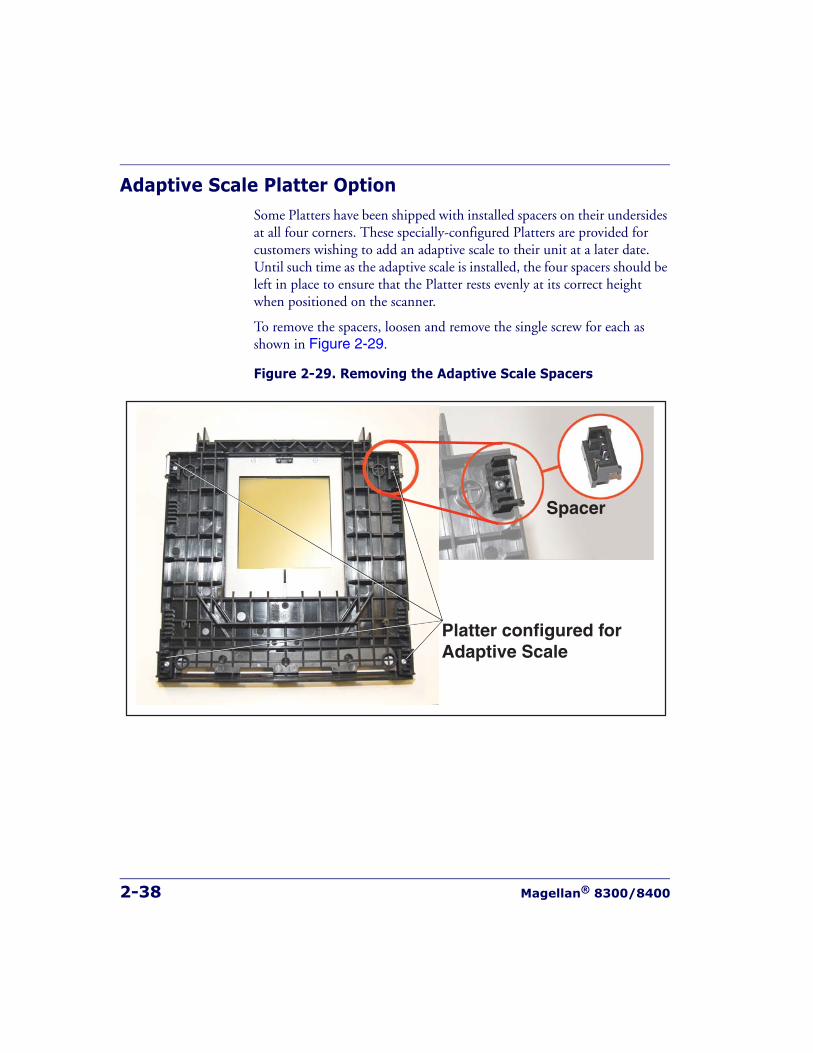
2-38 Magellan® 8300/8400
Adaptive Scale Platter OptionSome Platters have been shipped with installed spacers on their undersides at all four corners. These specially-configured Platters are provided for customers wishing to add an adaptive scale to their unit at a later date. Until such time as the adaptive scale is installed, the four spacers should be left in place to ensure that the Platter rests evenly at its correct height when positioned on the scanner.
To remove the spacers, loosen and remove the single screw for each as shown in Figure 2-29.
Figure 2-29. Removing the Adaptive Scale Spacers
Spacer
Platter configured forAdaptive Scale
System Power-Up Recap
Product Reference Guide 2-39
System Power-Up RecapThe System Power-Up procedure may vary depending upon the require-ments of your POS system. It is generally a good practice to power-down (switch off ) all equipment prior to connecting cables. Check with your System Supervisor and/or refer to your POS terminal manual for proper power-down and power-up procedures and interface requirements when connecting any peripheral device.
If you have not identified any specific requirements for your POS system, follow these steps.
1. Power-down the POS terminal.
2. Ensure that power is disconnected from the scanner.
3. Connect the scanner and scale interface cables to your POS termi-nal. This connection may use one or two cables depending upon your POS terminal interface.
4. [EAS units ONLY] Connect the EAS interface cable.
5. Connect the Remote Display cable if your model is a scanner/scale and make any connections to optional equipment, such as a hand-held scanner.
NOTE
SENSORMATIC EAS SYSTEMS:Always Apply power to the EAS Controller box before powering on the scan-ner.
2-40 Magellan® 8300/8400
6. Power-up the scanner or scanner/scale by connecting the power cord to an AC power outlet. Wait for the unit to complete the Self test routine (10 seconds maximum). Successful scanner power-up is sig-nified by any or all of the following:
- Facet wheel shows movement
- Lasers turn on
- Status LED(s) turn on
- Speaker sounds tone(s)
- Remote display [if present] shows message
- A single red dot is visible on the 7-segment display
7. Power-up the POS terminal. Verify that scanning, deactivation and weighing functions are operational and that data is properly com-municated between the scanner and your POS system. (Scan, deac-tivate and weigh a few items.) If problems are encountered, refer to Chapter 4, Problem Isolation.
8. You have now completed installation and system integration of the scanner or scanner/scale. At this point, the scale must be calibrated and certified in accordance with the requirements of your state and/or local requirements. Refer to Chapter 5, Calibration, for cali-bration procedures.
Product Reference Guide 3-1
Chapter 3
Operation andMaintenance
The information contained in this chapter describes how to operate and maintain the scanner, and optional scale and EAS systems. Topics include “how to’s” on scanning, EAS label deactivation, weighing, re-zeroing the scale, removing the top cover and cleaning the upper and lower windows.
Scanning ItemsTo scan items using the scanner, slide or push them through the scan zone as shown in Figure 3-1. The scanner will work equally well with either a left-to-right or right-to-left motion through the scan zone. There is rarely a need to reorient an item’s bar code since the scanner has a 360 degree view around an item.
NOTE
“Limited Scanning Mode” is entered by default by interfaces such as USBand IBM until a Point Of Sale (POS) terminal enables scanning. This modeallows the scanner to read labels without a host interface enabled. The scan-ner will only process programming labels and emit a bad label read indica-tion (“chirp”) for all other labels.
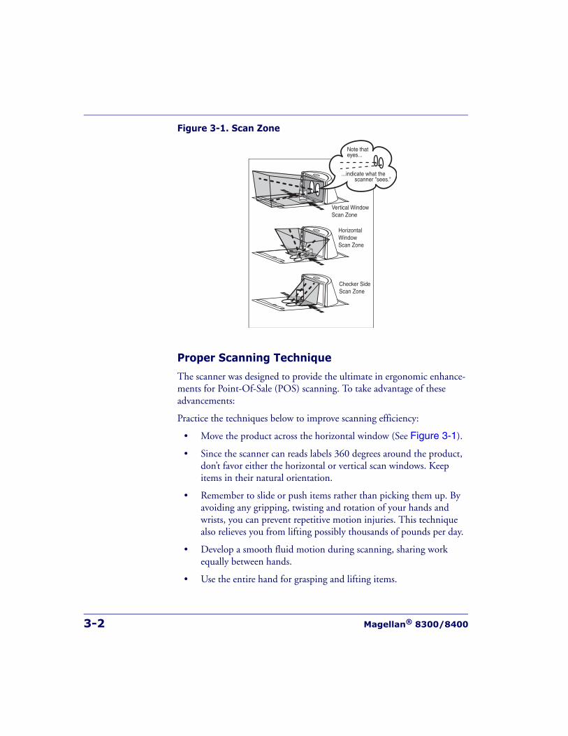
3-2 Magellan® 8300/8400
Figure 3-1. Scan Zone
Proper Scanning Technique
The scanner was designed to provide the ultimate in ergonomic enhance-ments for Point-Of-Sale (POS) scanning. To take advantage of these advancements:
Practice the techniques below to improve scanning efficiency:
• Move the product across the horizontal window (See Figure 3-1).
• Since the scanner can reads labels 360 degrees around the product, don’t favor either the horizontal or vertical scan windows. Keep items in their natural orientation.
• Remember to slide or push items rather than picking them up. By avoiding any gripping, twisting and rotation of your hands and wrists, you can prevent repetitive motion injuries. This technique also relieves you from lifting possibly thousands of pounds per day.
• Develop a smooth fluid motion during scanning, sharing work equally between hands.
• Use the entire hand for grasping and lifting items.
Vertical WindowScan Zone
HorizontalWindowScan Zone
Checker SideScan Zone
...indicate what the scanner "sees."
Note thateyes...
Product Reference Guide 3-3
• Develop efficient scanning motions, not necessarily faster hand movements.
• Learn typical locations for bar codes on packages; avoid “flipping” or rotating the items during scanning.
• Learn how the scanner functions and where the scanning area is located.
Deactivating Security LabelsEAS (Electronic Article Surveillance) labels can be detected and deacti-vated by a system equipped with this option. This is accomplished by means of a deactivation antenna mounted under the scanner platter. EAS labels should be brought near the antenna to be deactivated. Reference the documentation for the EAS device for more details about its installation and function.
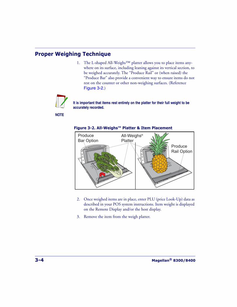
3-4 Magellan® 8300/8400
Proper Weighing Technique1. The L-shaped All-Weighs™ platter allows you to place items any-
where on its surface, including leaning against its vertical section, to be weighed accurately. The “Produce Rail” or (when raised) the “Produce Bar” also provide a convenient way to ensure items do not rest on the counter or other non-weighing surfaces. (Reference Figure 3-2.)
Figure 3-2. All-Weighs™ Platter & Item Placement
2. Once weighed items are in place, enter PLU (price Look-Up) data as described in your POS system instructions. Item weight is displayed on the Remote Display and/or the host display.
3. Remove the item from the weigh platter.
NOTE
It is important that items rest entirely on the platter for their full weight to beaccurately recorded.
All-Weighs®
PlatterProduceBar Option
ProduceRail Option
Operational Controls
Product Reference Guide 3-5
Operational ControlsThe function of scanner and scale controls and indicators is listed in Appendix A, LED/Beeper Indications & Controls. Turn to that appendix for full details.
Operational ModesThe scanner or scanner/scale features a number of modes that are impor-tant to both the user and the system support personnel. These modes can be combined into three groups: pre-operational, operational, and addi-tional functions. The following text describes these modes, what they mean, and how and when they are seen.
Power-Up/Selftest & Pre-Operation Pre-Operation describes those steps that must be successfully completed before the scanner sounds the initial good read tone and illuminates the lamps indicating the scanner and/or scale are ready for operation. These steps include Power-Up Selftest, Error Reporting, and Operational Con-figuration.
Power-Up/Selftest
Power-Up Selftest begins when power is applied. The scanner’s software immediately begins the testing sequence to verify that all systems are func-tioning properly. This routine, which only takes a few seconds, checks all the functions of the scanner, EAS deactivation system, scale, remote scale display and interface prior to indicating that it is ready for operation.
NOTE
A tone indicating Selftest is complete is a configurable feature. See the topicPower-up Beep Control in the Programming chapter of this manual.
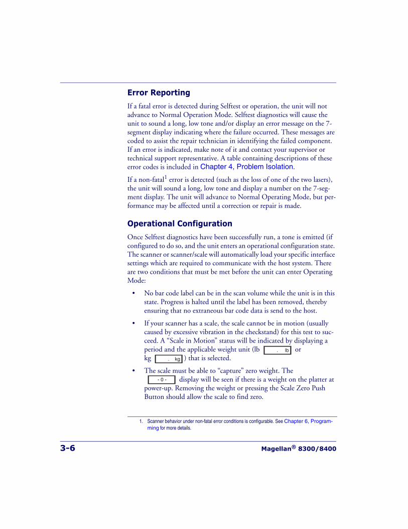
3-6 Magellan® 8300/8400
Error Reporting
If a fatal error is detected during Selftest or operation, the unit will not advance to Normal Operation Mode. Selftest diagnostics will cause the unit to sound a long, low tone and/or display an error message on the 7-segment display indicating where the failure occurred. These messages are coded to assist the repair technician in identifying the failed component. If an error is indicated, make note of it and contact your supervisor or technical support representative. A table containing descriptions of these error codes is included in Chapter 4, Problem Isolation.
If a non-fatal1 error is detected (such as the loss of one of the two lasers), the unit will sound a long, low tone and display a number on the 7-seg-ment display. The unit will advance to Normal Operating Mode, but per-formance may be affected until a correction or repair is made.
Operational Configuration
Once Selftest diagnostics have been successfully run, a tone is emitted (if configured to do so, and the unit enters an operational configuration state. The scanner or scanner/scale will automatically load your specific interface settings which are required to communicate with the host system. There are two conditions that must be met before the unit can enter Operating Mode:
• No bar code label can be in the scan volume while the unit is in this state. Progress is halted until the label has been removed, thereby ensuring that no extraneous bar code data is send to the host.
• If your scanner has a scale, the scale cannot be in motion (usually caused by excessive vibration in the checkstand) for this test to suc-ceed. A “Scale in Motion” status will be indicated by displaying a period and the applicable weight unit (lb or kg ) that is selected.
• The scale must be able to “capture” zero weight. The display will be seen if there is a weight on the platter at
power-up. Removing the weight or pressing the Scale Zero Push Button should allow the scale to find zero.
1. Scanner behavior under non-fatal error conditions is configurable. See Chapter 6, Program-ming for more details.
. lb
. kg
- 0 -
Operational Modes
Product Reference Guide 3-7
• When the scanner or scanner/scale completes its Selftest successfully, it emits a tone (when configured to do so) and enters Operating Mode.
Operating ModeOperating Mode includes Normal Operation (scanning, EAS deactivation and weighing) and Sleep Mode. These two modes are most commonly observed by the user/operator.
Normal Operation
This condition is indicated by the scanner green LED being on dim and steady. For scanner/scale models, the scale yellow LED indicates that the scale senses a weight of zero on the platter. If you have a scanner without scale model, the yellow lamp will not be lit when the scanner is ready for scanning.
Once the scanner enters Normal Operation, it begins a countdown sequence. If there is no activity during a preset period of time (also called time-out1), the unit will shut off the laser and/or motor in order to pro-long the life of the electrical and mechanical components. Once the scan-ner has timed out, it enters Sleep Mode.
NOTE
Yellow and Green LED indications are configurable. Your scanner may not beprogrammed to operate in the standard manner described above.
1. “Timeout” and “Sleep Mode” time delays are programmable features that can be selected through use of the programming labels included in Chapter 6, Programming.
3-8 Magellan® 8300/8400
Sleep Mode
After the scanner has been left idle for a preset period of time, the laser and/or motor automatically turns off (goes to sleep). This state is called Sleep Mode, and is indicated by a “slow” blink of the green light (blinking at a 2-second rate). To wake up the unit, press anywhere on the weigh platter (scanner/scale models only), press the Volume Selection switch or wave your hand over the horizontal window. The unit will recognize any of these signals as a wake-up call and instantly return to Normal Opera-tion.
Additional FunctionsAdditional scanner and scale functions include programming, running scanner or scale diagnostics, initiating a reset, zeroing the scale, and cali-brating the scale.
ProgrammingWhen your scanner or scanner/scale is shipped from the factory it is con-figured to work with the POS system interface at your store and read the bar code symbologies you designated. If you need to change this configu-ration information for any reason, Chapter 6, Programming, contains special bar code labels for changing the unit’s settings.
Diagnostic ModeRefer to Chapter 2, Diagnostic Modes, for details about running scan-ner and scale diagnostics. Turn to Chapter 4, Problem Isolation, for a description of error codes resulting from diagnostics.
Additional Functions
Product Reference Guide 3-9
Scanner and Scale ResetThe reset procedures and indicators are identical for scanner and scanner/scale models. As with any electronic equipment, it is sometimes necessary to reset the electronics. The reset procedure allows you to initiate a reset command to the scanner. This may be necessary if the POS terminal has been switched off or the store system has been reset while the unit is on. Reset can also be used to initiate and run the unit’s internal Selftest rou-tine.
Pressing and holding the Volume/Tone Push Button for approximately eight seconds initiates a reset, which is sounded by a rapid number of beeps. If the motor had been spinning, the lamps will blink while the motor spins down. At that point, the motor will spin back up and the scanner will continue to run the Selftest diagnostics. For more informa-tion, see the topic, Power-Up/Selftest & Pre-Operation, earlier in this chapter.
Scale AdjustmentsThe scale allows two user adjustments: zeroing and calibration. The first, and most frequently performed, is ‘zeroing’ the scale. This operation resets the scale’s “at rest” reading to zero which must be within the range of - 0.2 pounds (- 0.09kg) to +0.6 pounds (0.27kg) since the last calibration. While the ‘at rest’ reading remains within the zero range, the scale will automatically adjust itself to true zero. The scale also automatically zeros itself on power-up if the weight present on the scale is within these defined limits.
Zeroing the Scale
The zeroing operation may be performed by checkers and other store per-sonnel. Pressing and releasing the Scale Zero Push Button should return the scale to Normal Operation. If the zero point moves out of the zero range due to debris accumulation or other causes, pressing the Scale Zero Push Button will not reset the zero point. In this case the weigh platter must be cleaned, debris chutes cleared of debris or the scale must be recal-ibrated.

3-10 Magellan® 8300/8400
With the scanner/scale powered-up and at operating temperature:
1. Remove everything from the weighing surface of the scanner/scale.
2. Press the Scale Zero Push Button. (See Figure 1-1).
3. The Zero1 light will turn on and the display will show 0.00 lb (0.000 kg). If it does not, see Chapter 4, Problem Isolation.
4. You have completed the scale zeroing function.
Calibrating the Scale
The second adjustment, calibration, defines and sets a standard reference weight range against which all product weights are compared. If your scale is set for weighing in pounds, this range is 0 - 30 pounds, and, if your scale is set for weighing in kilograms, the range is 0 - 15 kilograms. The scale must be calibrated upon initial installation, whenever the scale cannot be zeroed, when the scale diagnostics indicate a calibration error, when the weighing measure (pounds or kilograms) is changed, or when the scale module has been replaced.
Normally, once the scale has been calibrated, the calibration must be veri-fied and/or approved by a local regulatory body. In many areas of the United States, the scale calibration switch must be sealed before being placed into service. Consult the agency responsible for regulating weigh-ing devices in your area to ensure that you are meeting all legal and regula-tory requirements. Chapter 5, Calibration, describes the calibration sequence and verification process.
Calibration can only be performed if the tamper seal that secures access to the Calibration Switch is broken and the switch cover is removed. Break-ing the seal may legally render the scale inoperable until it has been recerti-fied and a new seal attached. Consult your local regulations before removing the calibration seal if you are unsure of the legal requirements. Although the scale will physically continue to weigh products, a broken seal may require recertification by a proper authority as designated by your local laws.
1. Zero light operation is configurable.
Operational Maintenance
Product Reference Guide 3-11
Operational MaintenanceThe scanner or scanner/scale will provide dependable service for many years. The following maintenance procedures will keep your scanner or scanner/scale operating at peak performance.
Cleaning the Platter and Scan Windows. Clean the exterior surfaces of the horizontal and vertical scan windows at least twice daily with a nonabra-sive, mild, water-based glass cleaner and paper towels or lint-free cleaning tissues. The textured plastic surfaces and stainless steel can also be cleaned using the same cleaning agents.
Cleaning the Air Gap/Debris Chutes & Drip Rail. Daily, clear the debris chutes between the platter and the outer housing. Most items can be cleared from the debris chutes by carefully running a thin stiff object like a credit card along all sides of the weighing surface. If necessary, remove the top cover to clear the debris chutes and drip rail.
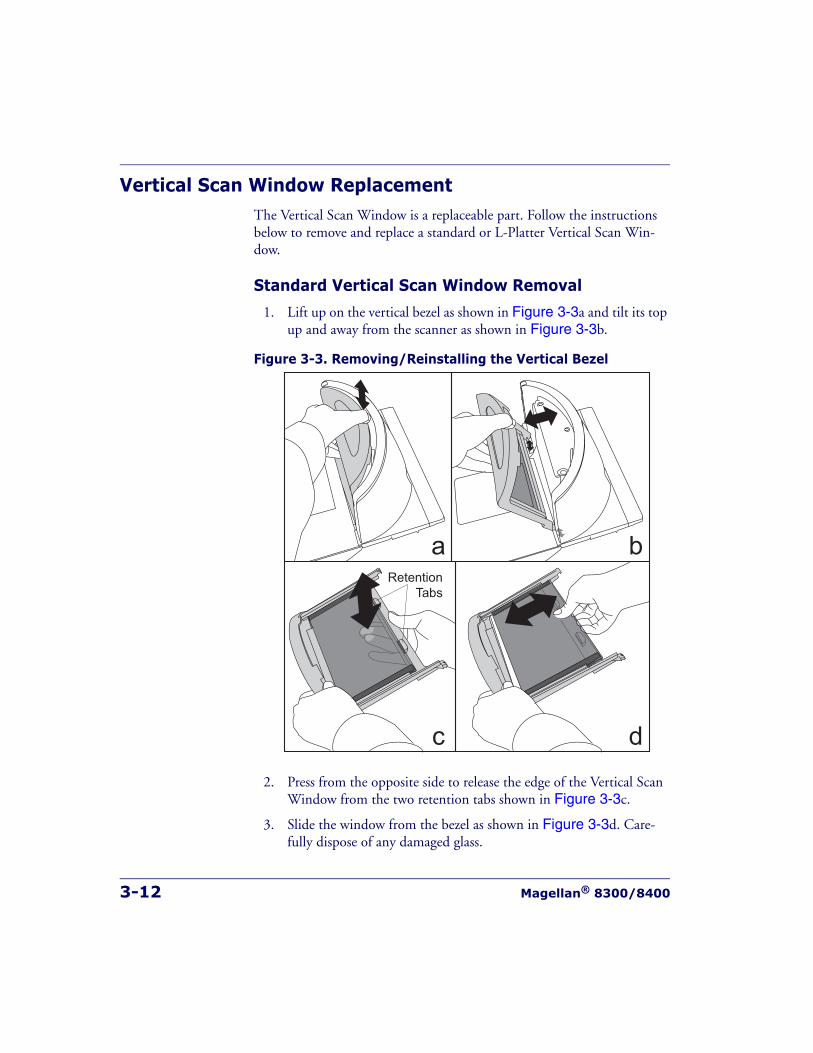
3-12 Magellan® 8300/8400
Vertical Scan Window ReplacementThe Vertical Scan Window is a replaceable part. Follow the instructions below to remove and replace a standard or L-Platter Vertical Scan Win-dow.
Standard Vertical Scan Window Removal
1. Lift up on the vertical bezel as shown in Figure 3-3a and tilt its top up and away from the scanner as shown in Figure 3-3b.
Figure 3-3. Removing/Reinstalling the Vertical Bezel
2. Press from the opposite side to release the edge of the Vertical Scan Window from the two retention tabs shown in Figure 3-3c.
3. Slide the window from the bezel as shown in Figure 3-3d. Care-fully dispose of any damaged glass.
a b
c d
RetentionTabs
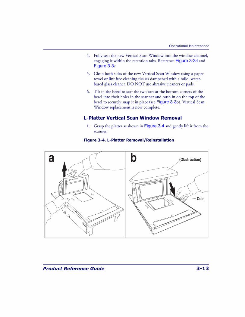
Operational Maintenance
Product Reference Guide 3-13
4. Fully seat the new Vertical Scan Window into the window channel, engaging it within the retention tabs. Reference Figure 3-3d and Figure 3-3c.
5. Clean both sides of the new Vertical Scan Window using a paper towel or lint free cleaning tissues dampened with a mild, water-based glass cleaner. DO NOT use abrasive cleaners or pads.
6. Tilt in the bezel to seat the two ears at the bottom corners of the bezel into their holes in the scanner and push in on the top of the bezel to securely snap it in place (see Figure 3-3b). Vertical Scan Window replacement is now complete.
L-Platter Vertical Scan Window Removal
1. Grasp the platter as shown in Figure 3-4 and gently lift it from the scanner.
Figure 3-4. L-Platter Removal/Reinstallation
a b
Coin
(Obstruction)
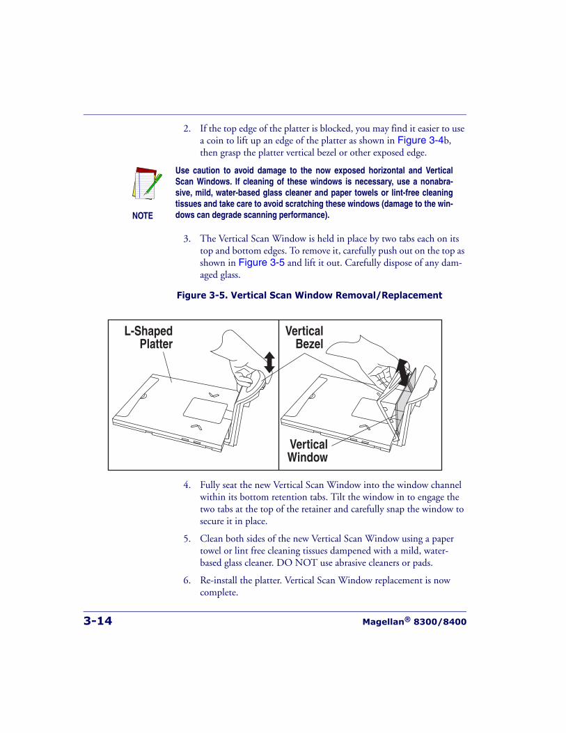
3-14 Magellan® 8300/8400
2. If the top edge of the platter is blocked, you may find it easier to use a coin to lift up an edge of the platter as shown in Figure 3-4b, then grasp the platter vertical bezel or other exposed edge.
3. The Vertical Scan Window is held in place by two tabs each on its top and bottom edges. To remove it, carefully push out on the top as shown in Figure 3-5 and lift it out. Carefully dispose of any dam-aged glass.
Figure 3-5. Vertical Scan Window Removal/Replacement
4. Fully seat the new Vertical Scan Window into the window channel within its bottom retention tabs. Tilt the window in to engage the two tabs at the top of the retainer and carefully snap the window to secure it in place.
5. Clean both sides of the new Vertical Scan Window using a paper towel or lint free cleaning tissues dampened with a mild, water-based glass cleaner. DO NOT use abrasive cleaners or pads.
6. Re-install the platter. Vertical Scan Window replacement is now complete.
NOTE
Use caution to avoid damage to the now exposed horizontal and VerticalScan Windows. If cleaning of these windows is necessary, use a nonabra-sive, mild, water-based glass cleaner and paper towels or lint-free cleaningtissues and take care to avoid scratching these windows (damage to the win-dows can degrade scanning performance).
VerticalWindow
VerticalBezel
L-ShapedPlatter
Operational Maintenance
Product Reference Guide 3-15
Horizontal Scan Window Replacement (WRG)Wear Resistant Glass (WRG) horizontal scan windows are replaceable and can be removed and replaced following the instructions below.
1. Remove the Platter from the scanner as shown in Figure 3-4.
2. Turn the platter upside down on a clean, dry surface and remove the two screws shown in Figure 3-6a. Retain the screws for later re-installation.
3. Tilt the Window Retainer up and away from the platter as shown.
4. Lift out the Window Gasket and WRG Window from the Platter as shown in Figure 3-6b and carefully dispose of any damaged glass.
5. Position the new WRG Window and its gasket as shown in Figure 3-6b.
6. Guide the Window Retainer to seat its edge under the tabs and match the screw holes as shown in Figure 3-6a.
7. Secure the retainer in position using the original two screws.
8. Clean both sides of the new WRG window using a paper towel or lint free cleaning tissues dampened with a mild, water-based glass cleaner. DO NOT use abrasive cleaners or pads.
9. Re-install the platter. WRG Window replacement is now complete.
NOTE
Sapphire glass does not require replacement, so it is permanently fastened inplace. Do not attempt to remove Sapphire glass from the platter.
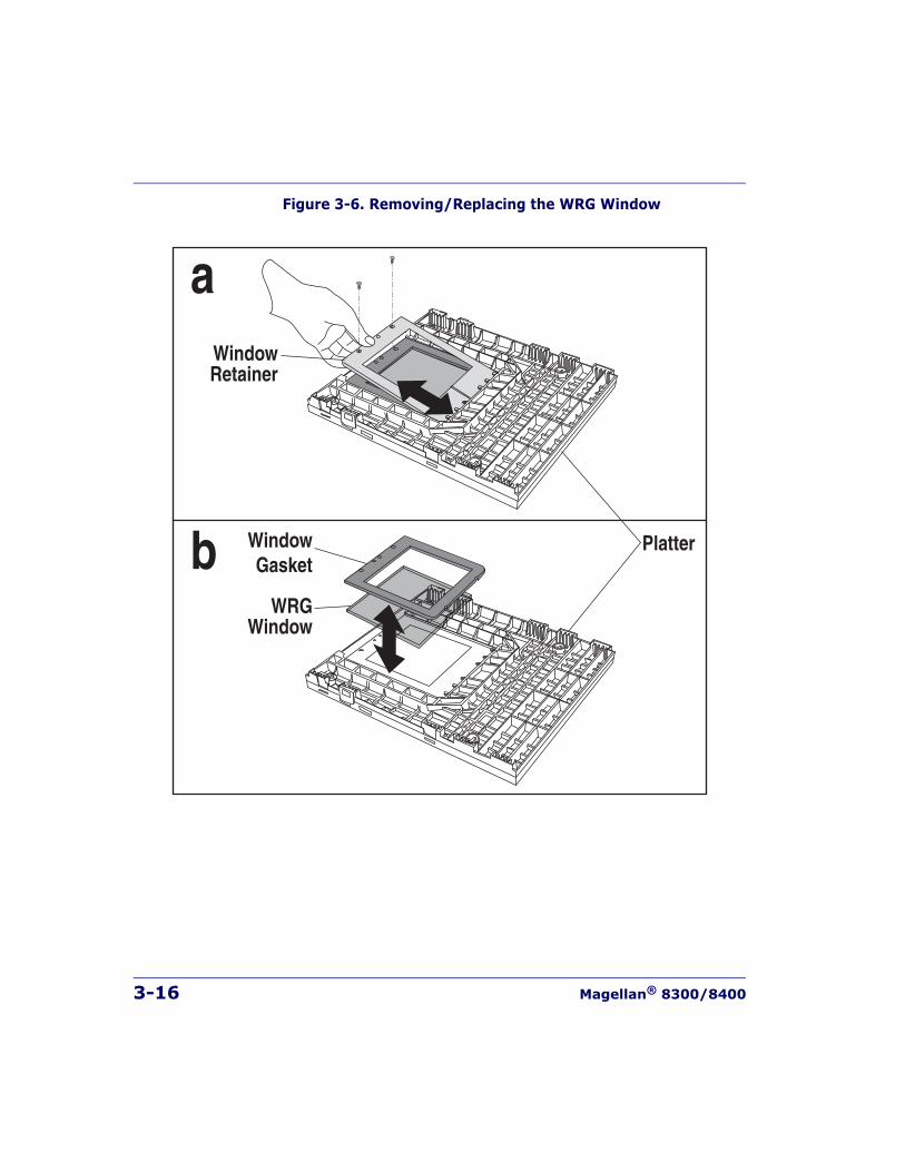
3-16 Magellan® 8300/8400
Figure 3-6. Removing/Replacing the WRG Window
PlatterWindowGasket
WRGWindow
WindowRetainer
a
b
Product Reference Guide 4-1
Chapter 4
Problem Isolation
In the event of a suspected functional problem, use the troubleshooting references provided in this chapter. This useful information will help you to identify and resolve the cause of the problem.
The scanner/scale has a number of features that indicate when a scanner or scale problem occurs. The unit may:
• emit a series of tones
• light the 7-segment (FRU status) display
• flash one or more LEDs
• display error codes on the Remote Display (if installed)
Three error reporting modes are used: Power-Up Selftest, Operational tests and Diagnostic tests. These test sequences are explained on the fol-lowing pages.
Power-Up Selftest
The Power-up Selftest is a pre-operational series of tests that must be suc-cessfully completed before the scanner indicates readiness for operation. This pre-operational period is the time between power-up and normal operation during which the motor comes up-to-speed and software, firm-ware and hardware are being tested. These tests ensure that all subsystems are fully functional before turning on the Visible Laser Diode (VLD). Refer to Chapter 3, Operational Modes for a more detailed description of this and other scanner and scale modes.
4-2 Magellan® 8300/8400
Operational Tests
These are the tests that run continually during Normal Operation and Sleep Mode. Firmware checks all subsystems, accessory connections and the POS interface to verify everything is operating normally. If a problem is detected at any time, a long, low tone is sounded, an error code is shown on the 7-segment display, and operation may be halted. If you press the Volume/Tone Push Button at that time, a series of tones will be sounded that matches the error code displayed.
Diagnostic Tests
See Chapter 2, Diagnostic Modes, for details about running diagnostic tests for the scanner and/or scale. If a problem is discovered during diag-nostics, the scanner will provide feedback about the source of the prob-lem. The remainder of this chapter describes these failure indications and includes troubleshooting flowcharts to help isolate the problem.
Diagnostic ProceduresYour Point-Of-Sale (POS) system may contain many components that operate as a system. Since almost all scanner or scale problems are caused by either the scanner, scale, POS terminal or communication links between them, these troubleshooting flowcharts focus on these compo-nents. Additionally, the optional Remote Scale Display, AC/DC Power Supply and their cables are potential problems addressed in this chapter.
The flowcharts provided in this chapter walk you through a diagnostic process that will isolate the failed component and instruct as to the correc-tive action required. Since internal scanner and scale components cannot be replaced by an operator or installer, most functional errors will require the assistance of a trained technical support person. However, if the prob-lem is caused by faulty cable, power supply or remote display, you can fix the problem by replacing the defective component and complete the installation.
Error Codes
Product Reference Guide 4-3
Error CodesIf an error is detected, the scanner will sound a long low tone (for one sec-ond) and alternately flash its LEDs, indicating a failure. Following the long low tone, an error code will appear on the 7-segment display (refer to Figure 4-1). Pressing the Volume/Tone Push button will cause the scanner to sound a series of beeps corresponding to that error code. Table 4-1 on the following page describes what these codes mean and what action should be taken for each.
NOTE
When troubleshooting, always remember to check all cable connectionsfirst before proceeding with other problem isolation steps.
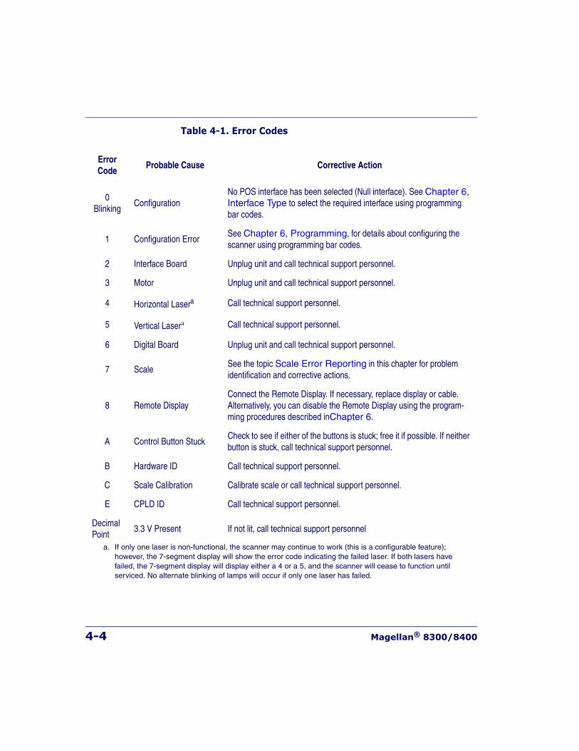
4-4 Magellan® 8300/8400
Table 4-1. Error Codes
Error Code
Probable Cause Corrective Action
0Blinking
ConfigurationNo POS interface has been selected (Null interface). See Chapter 6, Interface Type to select the required interface using programming bar codes.
1 Configuration ErrorSee Chapter 6, Programming, for details about configuring the scanner using programming bar codes.
2 Interface Board Unplug unit and call technical support personnel.
3 Motor Unplug unit and call technical support personnel.
4 Horizontal Lasera Call technical support personnel.
5 Vertical Lasera Call technical support personnel.
6 Digital Board Unplug unit and call technical support personnel.
7 ScaleSee the topic Scale Error Reporting in this chapter for problem identification and corrective actions.
8 Remote DisplayConnect the Remote Display. If necessary, replace display or cable. Alternatively, you can disable the Remote Display using the program-ming procedures described inChapter 6.
A Control Button StuckCheck to see if either of the buttons is stuck; free it if possible. If neither button is stuck, call technical support personnel.
B Hardware ID Call technical support personnel.
C Scale Calibration Calibrate scale or call technical support personnel.
E CPLD ID Call technical support personnel.
DecimalPoint
3.3 V Present If not lit, call technical support personnel
a. If only one laser is non-functional, the scanner may continue to work (this is a configurable feature); however, the 7-segment display will show the error code indicating the failed laser. If both lasers have failed, the 7-segment display will display either a 4 or a 5, and the scanner will cease to function until serviced. No alternate blinking of lamps will occur if only one laser has failed.
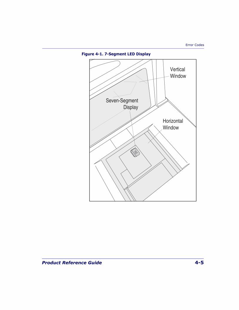
Error Codes
Product Reference Guide 4-5
Figure 4-1. 7-Segment LED Display
Seven-SegmentDisplay
HorizontalWindow
VerticalWindow
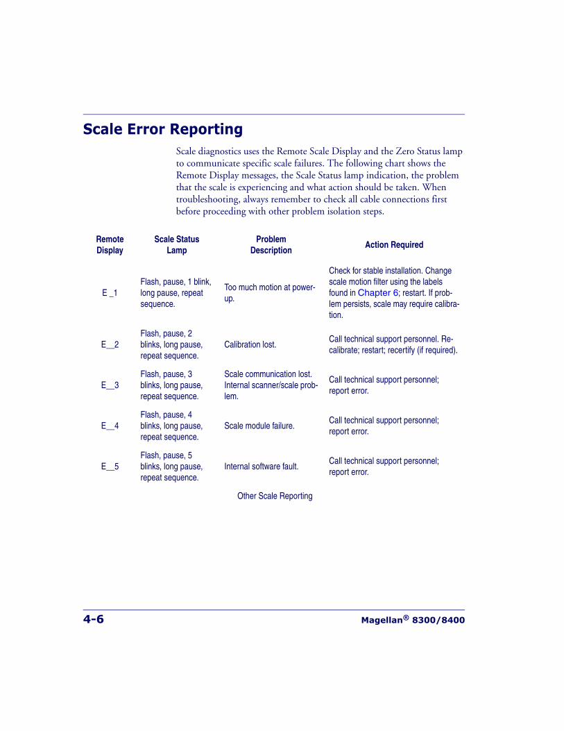
4-6 Magellan® 8300/8400
Scale Error ReportingScale diagnostics uses the Remote Scale Display and the Zero Status lamp to communicate specific scale failures. The following chart shows the Remote Display messages, the Scale Status lamp indication, the problem that the scale is experiencing and what action should be taken. When troubleshooting, always remember to check all cable connections first before proceeding with other problem isolation steps.
RemoteDisplay
Scale StatusLamp
Problem Description
Action Required
E _1Flash, pause, 1 blink, long pause, repeat sequence.
Too much motion at power-up.
Check for stable installation. Change scale motion filter using the labels found in Chapter 6; restart. If prob-lem persists, scale may require calibra-tion.
E__2Flash, pause, 2 blinks, long pause, repeat sequence.
Calibration lost.Call technical support personnel. Re-calibrate; restart; recertify (if required).
E__3Flash, pause, 3 blinks, long pause, repeat sequence.
Scale communication lost. Internal scanner/scale prob-lem.
Call technical support personnel; report error.
E__4Flash, pause, 4 blinks, long pause, repeat sequence.
Scale module failure.Call technical support personnel; report error.
E__5Flash, pause, 5 blinks, long pause, repeat sequence.
Internal software fault.Call technical support personnel; report error.
Other Scale Reporting
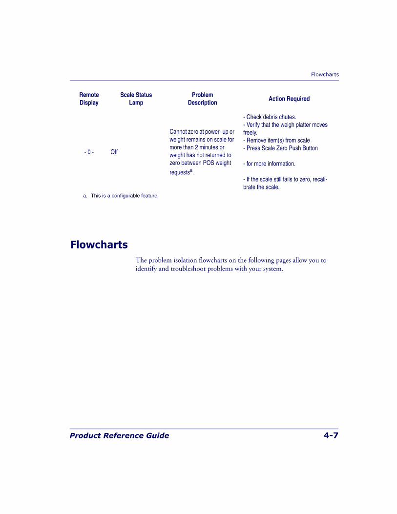
Flowcharts
Product Reference Guide 4-7
FlowchartsThe problem isolation flowcharts on the following pages allow you to identify and troubleshoot problems with your system.
- 0 - Off
Cannot zero at power- up or weight remains on scale for more than 2 minutes or weight has not returned to zero between POS weight
requestsa.
- Check debris chutes.- Verify that the weigh platter moves freely.- Remove item(s) from scale- Press Scale Zero Push Button
- for more information.
- If the scale still fails to zero, recali-brate the scale.
a. This is a configurable feature.
RemoteDisplay
Scale StatusLamp
Problem Description
Action Required
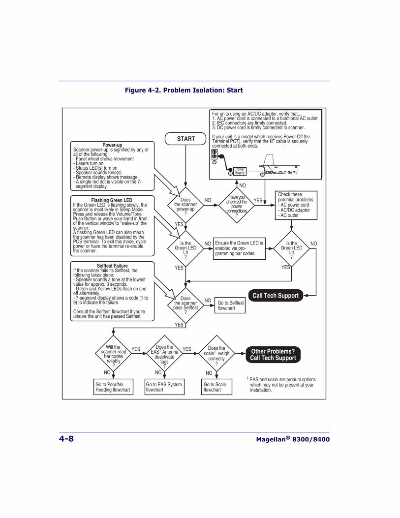
4-8 Magellan® 8300/8400
Figure 4-2. Problem Isolation: Start
START
YES
NODoesthe scannerpower-up
?
YES
NODoesthe scannerpass Selftest
?
YES
NOIs theGreen LED
Lit?
YES
NOIs theGreen LED
Lit?
YES
NO1 EAS and scale are product options which may not be present at your installation.
Will the scanner read
bar codesreliably
?
YES
NO
Have youchecked the
powerconnections
?
Check thesepotential problems:- AC power cord- AC/DC adaptor- AC outlet
Power-upScanner power-up is signified by any or all of the following:- Facet wheel shows movement- Lasers turn on- Status LED(s) turn on- Speaker sounds tone(s)- Remote display shows message- A single red dot is visible on the 7- segment display
Selftest FailureIf the scanner fails its Selftest, the following takes place:- Speaker sounds a tone at the lowest value for approx. 3 seconds.- Green and Yellow LEDs flash on and off alternately.- 7-segment display shows a code (1 to 9) to indicate the failure.
Consult the Selftest flowchart if you're unsure the unit has passed Selftest.
Flashing Green LEDIf the Green LED is flashing slowly, the scanner is most likely in Sleep Mode. Press and release the Volume/Tone Push Button or wave your hand in front of the vertical window to "wake-up" the scanner.A flashing Green LED can also mean the scanner has been disabled by the POS terminal. To exit this mode, cycle power or have the terminal re-enable the scanner.
For units using an AC/DC adapter, verify that...1. AC power cord is connected to a functional AC outlet.2. IEC connectors are firmly connected.3. DC power cord is firmly connected to scanner.
If your unit is a model which receives Power Off theTerminal POT), verify that the I/F cable is securelyconnected at both ends.
PowerSupply
Go to Selftestflowchart
Go to Poor/NoReading flowchart
NO
Go to EAS Systemflowchart
NO
Does thescale1 weigh
correctly?
Does theEAS1 Antenna
deactivatetags
?
Go to Scaleflowchart
Ensure the Green LED isenabled via pro-gramming bar codes.
YES
Call Tech Support
Other Problems?Call Tech Support
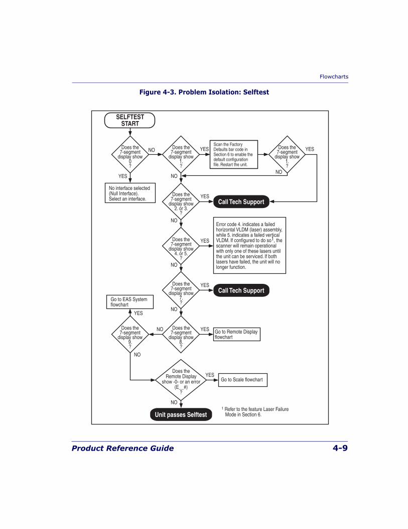
Flowcharts
Product Reference Guide 4-9
Figure 4-3. Problem Isolation: Selftest
Call Tech Support
Call Tech Support
Error code 4. indicates a failedhorizontal VLDM (laser) assembly, while 5. indicates a failed verticalVLDM. If configured to do so1, the scanner will remain operationalwith only one of these lasers untilthe unit can be serviced. If bothlasers have failed, the unit will no longer function.
1 Refer to the feature Laser Failure Mode in Section 6.
NO
YESDoes the7-segment
display show2. or 3.
?
NO
YESDoes the7-segment
display show4. or 5.
?
NO
NO
YESDoes the7-segment
display show7.?
NO
YESDoes the7-segment
display show8.?
Does the7-segment
display show9.?
Go to Remote Displayflowchart
Go to EAS Systemflowchart
Go to Scale flowchart
Unit passes Selftest
YESDoes the
Remote Displayshow -0- or an error
(E__#)?
YES
NODoes the7-segment
display show0?
YES YES
NONO
Does the7-segment
display show1.?
Does the7-segment
display show1.?
SELFTESTSTART
No interface selected(Null Interface). Select an interface.
Scan the FactoryDefaults bar code inSection 6 to enable thedefault configurationfile. Restart the unit.
YES
NO
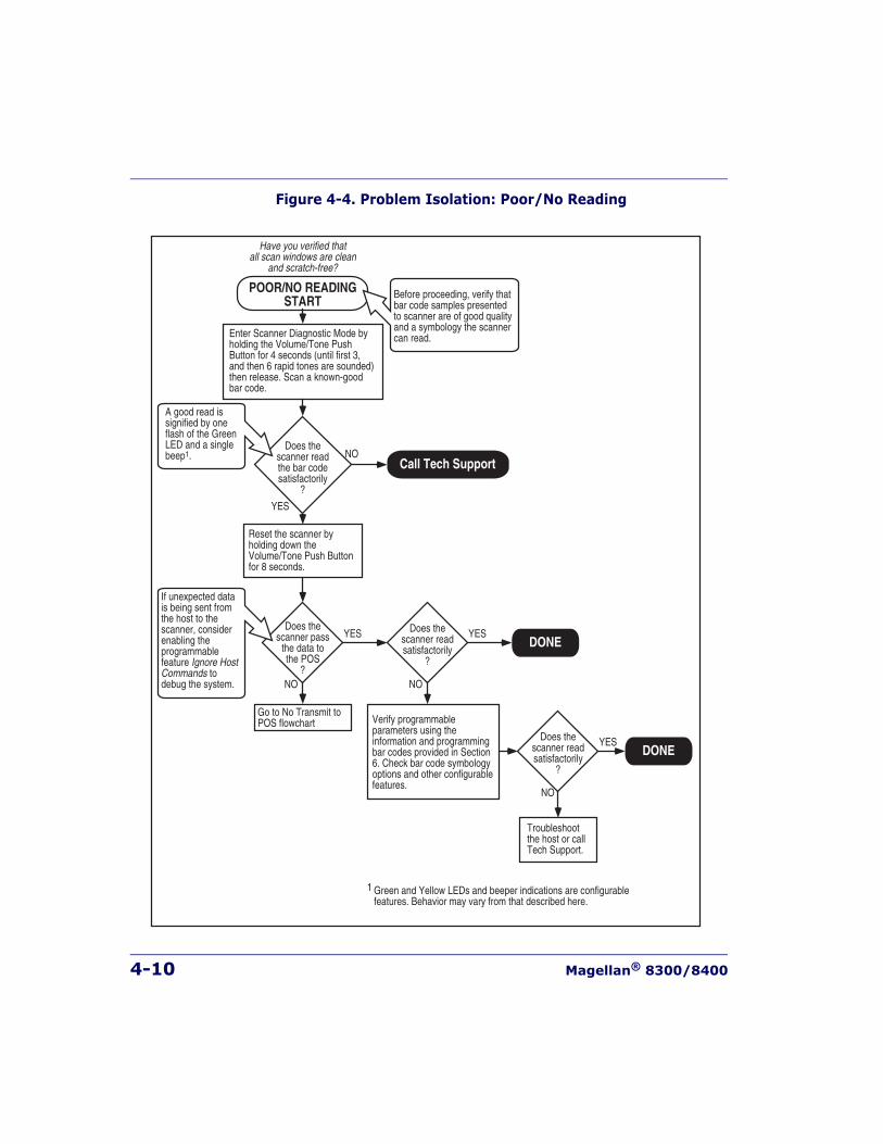
4-10 Magellan® 8300/8400
Figure 4-4. Problem Isolation: Poor/No Reading
DONE
DONE
POOR/NO READINGSTART
Have you verified thatall scan windows are clean
and scratch-free?
YES
NODoes the
scanner readthe bar codesatisfactorily
?
Verify programmable parameters using the information and programming bar codes provided in Section 6. Check bar code symbology options and other configurable features.
Reset the scanner by holding down the Volume/Tone Push Button for 8 seconds.
Troubleshootthe host or call Tech Support.
YES
NO
Does thescanner pass
the data tothe POS
?
YES
NO
Does thescanner readsatisfactorily
?
YES
NO
Does thescanner readsatisfactorily
?
Enter Scanner Diagnostic Mode by holding the Volume/Tone Push Button for 4 seconds (until first 3, and then 6 rapid tones are sounded) then release. Scan a known-good bar code.
A good read is signified by one flash of the Green LED and a single beep1.
If unexpected data is being sent from the host to the scanner, consider enabling the programmablefeature Ignore HostCommands to debug the system.
Before proceeding, verify that bar code samples presented to scanner are of good quality and a symbology the scanner can read.
Green and Yellow LEDs and beeper indications are configurable features. Behavior may vary from that described here.1
Call Tech Support
Go to No Transmit toPOS flowchart
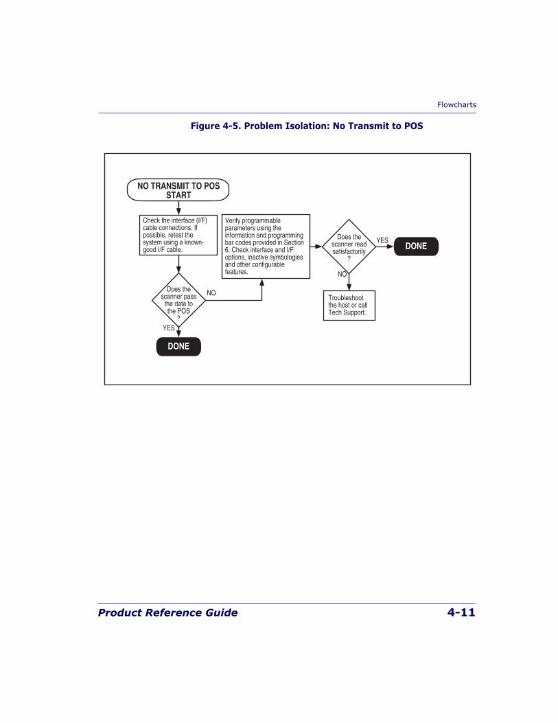
Flowcharts
Product Reference Guide 4-11
Figure 4-5. Problem Isolation: No Transmit to POS
DONE
DONE
NO TRANSMIT TO POSSTART
Verify programmable parameters using the information and programming bar codes provided in Section 6. Check interface and I/F options, inactive symbologies and other configurable features.
Troubleshootthe host or call Tech Support.
YES
NO
Does thescanner readsatisfactorily
?
Check the interface (I/F) cable connections. If possible, retest the system using a known-good I/F cable.
YES
NODoes thescanner pass
the data tothe POS
?
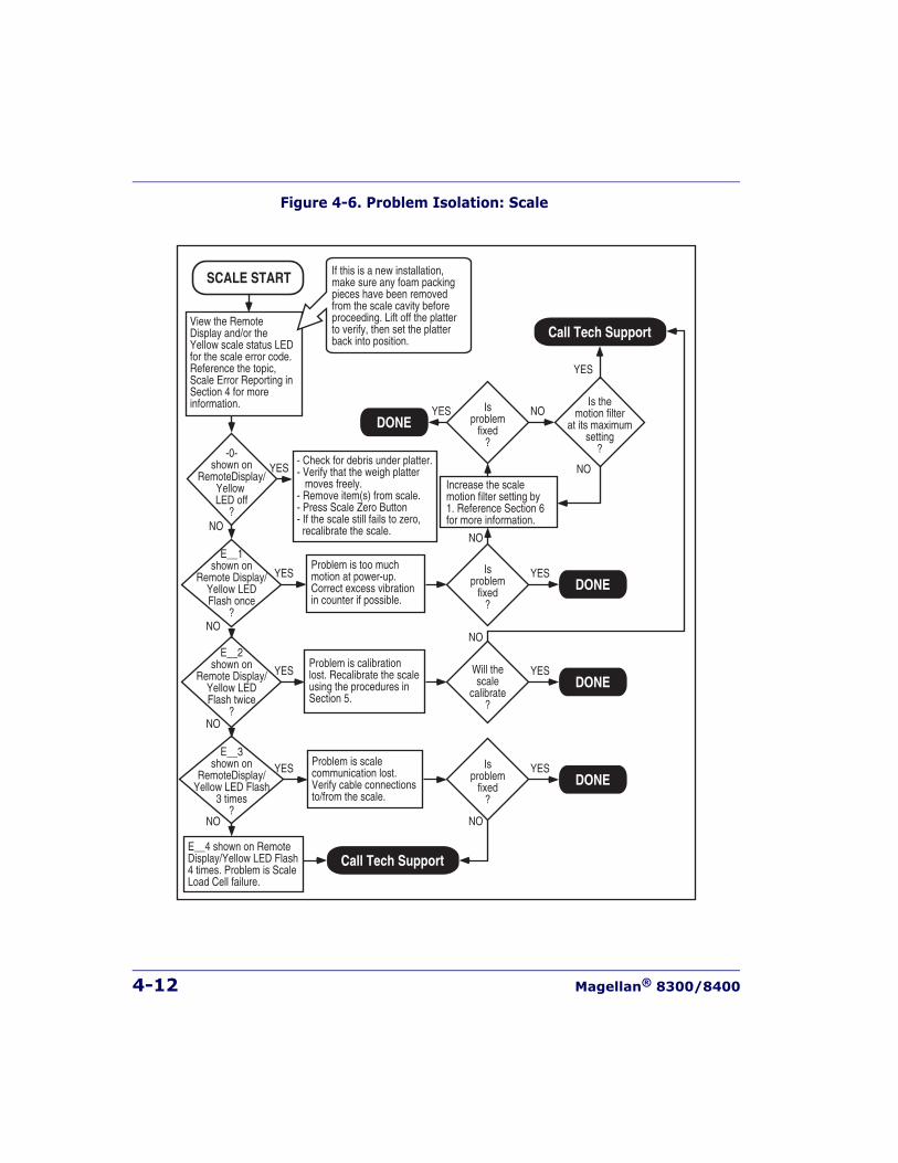
4-12 Magellan® 8300/8400
Figure 4-6. Problem Isolation: Scale
SCALE START
View the Remote Display and/or the Yellow scale status LED for the scale error code. Reference the topic, Scale Error Reporting in Section 4 for more information.
Problem is too much motion at power-up. Correct excess vibration in counter if possible.
Increase the scale motion filter setting by 1. Reference Section 6 for more information.
NO
YES
E__1shown on
Remote Display/Yellow LEDFlash once
?
Problem is calibration lost. Recalibrate the scale using the procedures in Section 5.
NO
YES
E__2shown on
Remote Display/Yellow LEDFlash twice
?
- Check for debris under platter.- Verify that the weigh platter moves freely.- Remove item(s) from scale.- Press Scale Zero Button- If the scale still fails to zero, recalibrate the scale.NO
YES-0-
shown onRemoteDisplay/
YellowLED off
?
NO
NO
NO
YESIsproblem
fixed?
NOIsproblem
fixed?
NO
YES
YESIs the
motion filterat its maximum
setting?
DONE
YESWill thescale
calibrate?
Problem is scale communication lost. Verify cable connections to/from the scale.
NO
YESE__3
shown onRemoteDisplay/
Yellow LED Flash3 times
?
E__4 shown on RemoteDisplay/Yellow LED Flash4 times. Problem is ScaleLoad Cell failure.
YESIsproblem
fixed?
DONE
DONE
DONE
Call Tech Support
Call Tech Support
If this is a new installation, make sure any foam packing pieces have been removed from the scale cavity before proceeding. Lift off the platter to verify, then set the platter back into position.
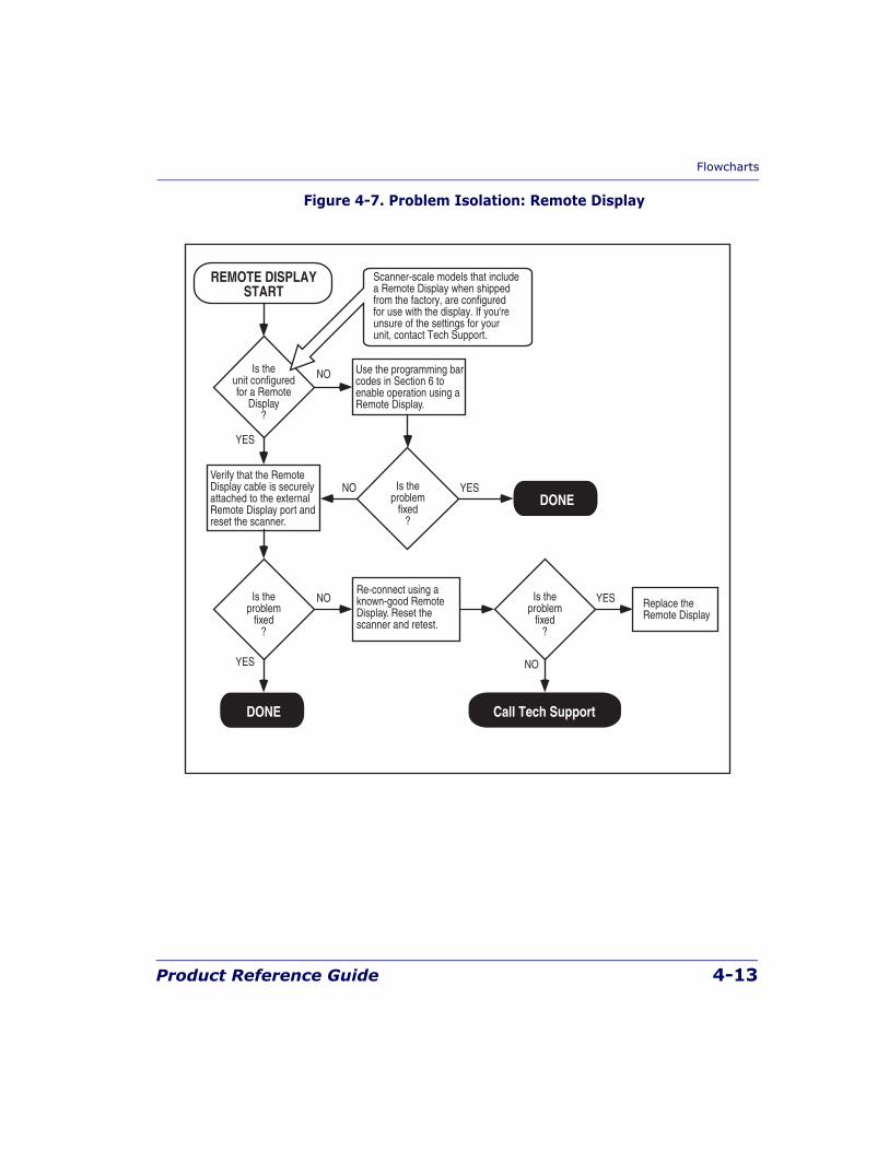
Flowcharts
Product Reference Guide 4-13
Figure 4-7. Problem Isolation: Remote Display
Call Tech Support
DONE
DONE
REMOTE DISPLAYSTART
YES
YES
YES
YES
NO
NO
NO
NO
Is theunit configuredfor a Remote
Display?
Is theproblem
fixed?
Is theproblem
fixed?
Is theproblem
fixed?
Replace theRemote Display
Use the programming bar codes in Section 6 to enable operation using a Remote Display.
Verify that the Remote Display cable is securely attached to the external Remote Display port and reset the scanner.
Scanner-scale models that include a Remote Display when shipped from the factory, are configured for use with the display. If you're unsure of the settings for your unit, contact Tech Support.
Re-connect using a known-good Remote Display. Reset the scanner and retest.
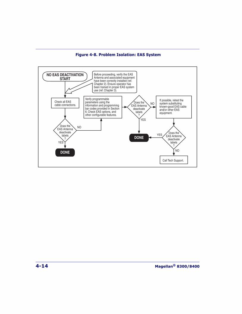
4-14 Magellan® 8300/8400
Figure 4-8. Problem Isolation: EAS System
DONE
DONE
NO EAS DEACTIVATIONSTART
Verify programmableparameters using the information and programmingbar codes provided in Section6. Check EAS options, andother configurable features.
Call Tech Support.
YES
YES
NO
NO
Does theEAS Antenna
deactivatelabels
?
Does theEAS Antenna
deactivatelabels
?
Check all EAScable connections.
If possible, retest the system substitutingknown-good EAS cableand/or other EASequipment.
YES
NODoes theEAS Antenna
deactivatelabels
?
Before proceeding, verify the EASAntenna and associated equipmenthave been correctly installed (ref. Chapter 2). Ensure operator hasbeen trained in proper EAS systemuse (ref. Chapter 3).
Product Reference Guide 5-1
Chapter 5
Calibration
A number of situations require the scale to be calibrated. They are:
• at initial installation of the scanner/scale
• if the scale cannot be re-zeroed
• if you change the weight measure from pounds to kilograms or vice-versa
• if diagnostics indicate a calibration error
• the weigh module has been replaced
Follow the procedures on the following pages to ensure that the scanner/scale will meet Weights and Measurement requirements.
Certification of the scanner/scale’s weighing apparatus is subject to Fed-eral, State and Local Weights and Measures statutes and is restricted toauthorized government agencies and/or duly registered agents thereof.Anytime a scale is calibrated, it should be properly sealed with a lead andwire or paper seal before being placed into service.
It is your responsibility to check with the appropriate authorities in yourarea to ensure compliance with pertinent regulations before removingany official seals or placing a newly calibrated scanner/scale into ser-vice.
LEGAL NOTE
5-2 Magellan® 8300/8400
Description of Calibration SequenceThe Calibration Sequence sets the scale to an accurate reference point for weighing. This process involves the use of a Field Standard Weight Set (31.5-pounds) for calibration in pounds, (18.5-kilograms) for Metric. Once calibration has been successfully completed, the scanner/scale uses the certified weight as a reference for subsequent weighing activities.
These verification procedures follow the U.S. National Institute of Stan-dards and Technology 44 Handbook guidelines for bench/counter scale installations.
If any of these tests fail to meet the required weight indications, you must calibrate the scanner/scale. Refer to the calibration procedures in this chapter for the proper procedures.
You may be required by state and/or local regulations to have procedures other than these performed by a certified technician or verification offi-cial.
Access to the calibration switch should be restricted with a paper or a wire and lead seal after the calibration has been performed if required by your local regulatory agency.
The following tools and supplies will be required to perform the calibra-tion process:
• 31.5 pound Field Standard Weight Set1.(English calibration only).
• 18.5 kilogram Field Standard Weight Set2.(Metric calibration only).
NOTE
The Calibration Sequence must be performed without removing the scanner/scale from its installed position.
1. NOTE: Throughout the calibration procedures, specified weights may be achieved by using a com-bination of weights from this set. eg. 20 lbs may be made up of one 10.00 lb. weight and two 5.00 lb. weights.
2. NOTE: Throughout the calibration procedures, specific weights may be achieved by using a com-bination of weights from this set. eg. 10 kgs. may be made up of one 5.00 kg. and five 1.00 kg. weights.
Motion Test
Product Reference Guide 5-3
• Lead/Wire or Paper Seal (as required by law).
Motion TestThis test verifies that the scale will not ‘zero’ when the weighing surface of the scanner/scale is in motion.
1. Verify that the Yellow LED1 is on and the Remote Display reads 0.00 pounds or 0.000 kilograms.
2. Press lightly on the weigh platter of the scanner/scale with one hand and at the same time press and release the Zero Push Button on the operator’s panel. The Yellow LED should turn Off and the Remote Display should not display 0.00 pounds or 0.000 kilograms.
3. Remove your hand from the weighing platform and verify that the Yellow LED is On and the Remote Display reads 0.00 pounds or 0.000 kilograms.
Automatic Zero Tracking TestThis test verifies that the scanner/scale automatic zero tracking mecha-nism is operating correctly.
1. Place 0.006 pounds (3 grams for metric) on the center of the weigh-ing platform. The entire weight must be placed on the weighing platform at once for this test to be valid. The Yellow LED should go Off and the Remote Display should read 0.01 pounds (0.005 kilo-grams).
1. Yellow LED indications can be configured via feature programming and may not be enabled for certain functions.
NOTE
The scanner/scale has an adaptive zero capture mechanism that re-zeros thescale over time if there is a slow change in the zero level; thus if all the weightis not placed on the weighing surface at one time, the Yellow LED will remainOn and the Remote Display will read 0.00 pounds (0.000 kilograms). When theweight is removed, the Yellow LED will turn off and the display will show a
minus sign . Press the Zero Push Button to re-zero the scale.. lb

5-4 Magellan® 8300/8400
Preparing the Scanner/Scale for Calibration1. Assure that the scanner/scale is stable, secure and properly installed.
(Refer to Chapter 2, Site Preparation and Installation, for instruc-tions on the proper installation of the scanner/scale).
2. Power-up the scanner/scale.
3. Allow the unit to reach temperature equilibrium for at least one hour. If the scanner/scale is already at room temperature, allow at least 15 minutes for acclimatization.
4. Before performing the calibration, the scanner/scale must be pre-stressed with a weight of more than 30 pounds (15kg). With power turned on, place the entire weight set (including the case) on the weighing surface of the scale. The display should show an under-
score and three hyphens , which is the overweight indica-tion.
5. Remove all weight from the weighing surface and ensure that there are no obstructions in the debris chutes of the scanner/scale. See Figure 2-5.
Calibrating the Scale (Pounds & Kilograms)1. Before proceeding, ensure that the scanner/scale has been prepared
for this process by performing the preceding steps titled, Preparing the Scanner/Scale for Calibration.
2. Remove the weigh platter and make sure that there are no obstruc-tions in the debris chutes.
3. Cut and remove the seal that secures the calibration switch access cover as shown in Figure 5-1. The seal may not be present if this is the initial installation of the scanner/scale.
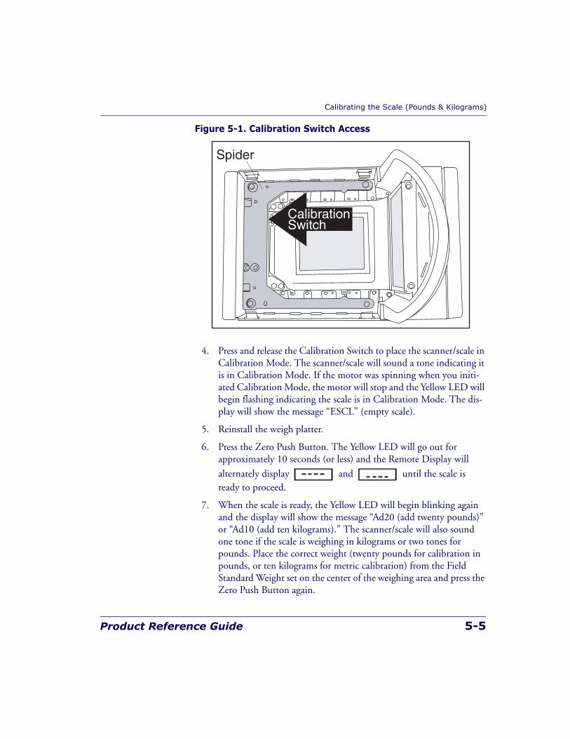
Calibrating the Scale (Pounds & Kilograms)
Product Reference Guide 5-5
Figure 5-1. Calibration Switch Access
4. Press and release the Calibration Switch to place the scanner/scale in Calibration Mode. The scanner/scale will sound a tone indicating it is in Calibration Mode. If the motor was spinning when you initi-ated Calibration Mode, the motor will stop and the Yellow LED will begin flashing indicating the scale is in Calibration Mode. The dis-play will show the message “ESCL” (empty scale).
5. Reinstall the weigh platter.
6. Press the Zero Push Button. The Yellow LED will go out for approximately 10 seconds (or less) and the Remote Display will
alternately display and until the scale is ready to proceed.
7. When the scale is ready, the Yellow LED will begin blinking again and the display will show the message “Ad20 (add twenty pounds)” or “Ad10 (add ten kilograms).” The scanner/scale will also sound one tone if the scale is weighing in kilograms or two tones for pounds. Place the correct weight (twenty pounds for calibration in pounds, or ten kilograms for metric calibration) from the Field Standard Weight set on the center of the weighing area and press the Zero Push Button again.
Spider
CalibrationSwitch
5-6 Magellan® 8300/8400
8. The Yellow LED will extinguish for approximately 10 seconds and
the Remote Display will alternately display and
until the scale is ready to proceed.
9. If the calibration was successful, the speaker sounds a single tone, the Scale Status LED begins blinking again, and “End-” appears in the Remote Display.
10. If the calibration was not successful, the speaker will sound five tones indicating a scale failure, and the Scale Status LED will blink twice, strobe (fast blinks) and then continually repeat this sequence until reset. Remove all weight from the Weigh Platter, and repeat the procedure starting with step 7.
11. Press the Zero Push Button again to permanently store the calibra-tion data and exit Calibration Mode. You have completed the cali-bration of the scanner/scale. The unit’s calibration must now be verified as required by state and/or local weights and measures regu-lations. The verification procedure must be performed to assure that a scale will pass Weights and Measures requirements before it is placed into commercial/retail service.
You have completed the scale calibration procedure. You must now con-tinue with the calibration verification tests to complete the scale’s calibra-tion. If you are weighing in pounds, continue with the following procedures to verify that the scale was successfully calibrated and that it weighs properly. If you are weighing in kilograms, turn to the instructions titled, Calibration Verification (Kilograms), later in this chapter.
Calibration Verification (U.S. Pounds)
Product Reference Guide 5-7
Calibration Verification (U.S. Pounds)Once you have completed the calibration sequence, you may be required to perform these step-by-step verification procedures. These procedures follow the National Institute of Standards and Technology Handbook-44guidelines for grocery scale installations. You may be required by state or local law to have these procedures performed by a certified technician or verified by a proper official.
These calibration verification procedures cover five different tests:
• Increasing-Load Test
• Shift Test
• Blanking Test
• Decreasing-Load Test
• Return to Zero Test
Increasing-Load Test (Phase 1)This test checks Scale operation with five, ten and fifteen pound weights.
1. Check that the display reads 0.00 lb. when at rest with nothing on the weighing surface. (The Yellow LED is steadily lit).
2. Place a five-pound weight on the center of the weighing surface and check that the display reads 5.00 lb.
3. Place an additional five pounds on the center of the weighing sur-face and check that the display reads between 9.99 and 10.01 lb.
4. Place an additional five pounds on the center of the weighing sur-face and check that the display reads between 14.99 and 15.01. Remove the weights and verify that the display reads 0.00.
5. You have completed the Increasing-Load Test (Phase 1).
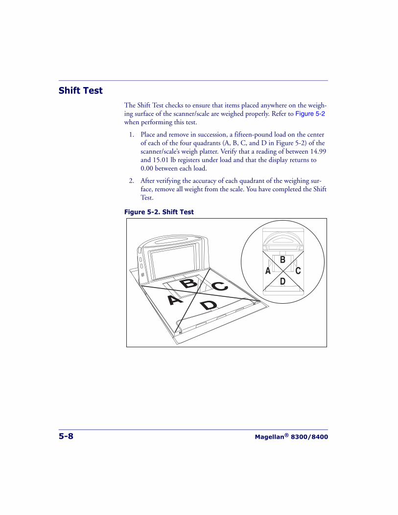
5-8 Magellan® 8300/8400
Shift TestThe Shift Test checks to ensure that items placed anywhere on the weigh-ing surface of the scanner/scale are weighed properly. Refer to Figure 5-2when performing this test.
1. Place and remove in succession, a fifteen-pound load on the center of each of the four quadrants (A, B, C, and D in Figure 5-2) of the scanner/scale’s weigh platter. Verify that a reading of between 14.99 and 15.01 lb registers under load and that the display returns to 0.00 between each load.
2. After verifying the accuracy of each quadrant of the weighing sur-face, remove all weight from the scale. You have completed the Shift Test.
Figure 5-2. Shift Test
ACB
D
A CB
D
Calibration Verification (U.S. Pounds)
Product Reference Guide 5-9
Increasing- Load Test (Phase 2)After completing the Shift Test, you must complete the Increasing Load Test using 20.0, 25.0 and 30.0 pounds of weight.
1. With the scale starting at zero, place 20.0 pounds in the center of the weighing surface and check that the display reads between 19.99 and 20.01 lb.
2. Place an additional five pounds in the center of the weighing sur-face, increasing the load to 25.0 pounds and check that the display reads between 24.99 and 25.01 lb.
3. Place an additional five pounds in the center of the weighing surface increasing the load to 30.0 pounds and check that the display reads between 29.99 and 30.01 lb.
4. Remove the weights and verify that the display reads 0.00.
Blanking TestThis test ensures that the scanner/scale will indicate its weighing capability has been exceeded if a weight greater than 0.05 pounds over its maximum upper weight limit is placed upon the unit.
1. Place weights that total the upper weight limit plus 0.051 pounds on the scale. For example: If the upper limit is set at 30 pounds, place weights equaling 30.051 pounds.
2. Verify that the display shows a dash and three hyphens (_ - - -). This is the overweight indication.
NOTE
The upper limit of the scale is configurable according to POS interface typeand may not necessarily be set at 30 pounds, which is the standard setting.For this test, continue to place weights in five pound increments only up tothe upper weight limit set for your scale.
NOTE
The scanner/scale may blank (show an underscore and three hyphens) at anyweight greater than its upper limit, but must blank when the upper limit plus0.051 pounds are set upon the weighing surface.
5-10 Magellan® 8300/8400
Decreasing-Load TestThis test ensures that the scanner/scale responds properly when a heavy object is followed by a significantly smaller object.
1. Place a 30.0-pound load on the scale and verify that the display shows between 29.99 and 30.01 pounds.
2. Remove weights to leave 20 pounds on the scale. Check that the dis-play shows between 19.99 and 20.01.
3. Remove another 15.0 pounds from the scale and check that the scale reads 5.00 lb.
4. You have completed the Decreasing Load Test.
Return to Zero TestThis test ensures that, after all other tests have been completed success-fully, the scanner/scale returns to zero. Remove all weights from the scale and verify that the scale reads 0.00 lb.
After completing this test, close the calibration access cover and seal per local Weights and Measures requirements. This final step must agree with the legal requirements of your state or local government.
You have completed the calibration and verification process for weighing in pounds.
If the scanner/scale passes all these tests,
1. Remove the weigh platter, install the calibration switch cover and install a seal (if required).
2. Reinstall the weigh platter.
If the scanner/scale fails any of these tests, it should be serviced by a quali-fied technician.
NOTE
If the upper weight limit for your scale is not set at 30 pounds, begin by plac-ing weight equaling your upper limit setting.
Calibration Verification (Kilograms)
Product Reference Guide 5-11
Calibration Verification (Kilograms)Once you have completed the calibration sequence, you may be required to perform these step-by-step verification procedures. These procedures follow the National Institute of Standards and Technology Handbook-44guidelines for grocery scale installations. You may be required by state or local law to have these procedures performed by a certified technician or verified by a proper official.
These calibration verification procedures cover five different tests:
• Increasing-Load Test
• Shift Test
• Blanking Test
• Decreasing-Load Test
• Return to Zero Test
Increasing-Load Test (Phase 1)This test checks Scale operation for increasing loads from 0.100 kg and 7.50 kg.
1. Check that the display reads 0.000 kg when at rest with nothing on the weighing surface. (The Yellow LED is steadily lit).
2. Place a 100 gram weight on the center of the weighing surface and check that the display reads 0.100 kg.
3. Place an additional 200 grams on the center of the weighing surface and check that the display reads 0.300 kg.
4. Place an additional 200 grams on the center of the weighing surface and check that the display reads 0.500 kg.
5. Place an additional 100 grams on the center of the weighing surface and check that the display reads 0.600 kg.
6. Place an additional 100 grams on the center of the weighing surface and check that the display reads 0.700 kg.
7. Place an additional 100 grams on the center of the weighing surface and check that the display reads 0.800 kg.
5-12 Magellan® 8300/8400
8. Place an additional 200 grams on the center of the weighing surface and check that the display reads 1.000 kg.
9. Increase the weight on the scale to 7.50 kg on the center of the weighing surface and check that the display reads between 7.495 and 7.505 kg.
10. Remove the weights and verify that the display reads 0.000 kg. You have completed the Increasing-Load Test (Phase 1).
Shift Test (Metric)The Shift Test checks to ensure that items placed anywhere on the weigh-ing surface of the scanner/scale are weighed properly. Refer to Figure 5-3when performing this test.
1. Place and remove in succession, a 5.0 kilogram load on the center of each of the four quadrants (A, B, C, and D in Figure 5-3) and in the center of the scanner/scale’s weighing platform. Verify that the dis-play shows a reading of between 4.995 and 5.005 kg for each quad-rant/center test and that the display returns to 0.000 between each load.
2. After verifying the accuracy of each quadrant and the center of the weighing surface, remove all weight from the scale. You have com-pleted the Shift Test.
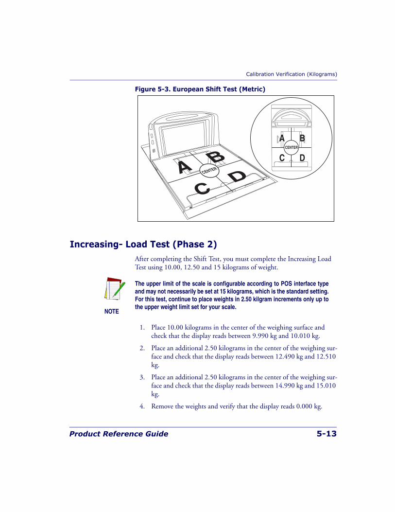
Calibration Verification (Kilograms)
Product Reference Guide 5-13
Figure 5-3. European Shift Test (Metric)
Increasing- Load Test (Phase 2)After completing the Shift Test, you must complete the Increasing Load Test using 10.00, 12.50 and 15 kilograms of weight.
1. Place 10.00 kilograms in the center of the weighing surface and check that the display reads between 9.990 kg and 10.010 kg.
2. Place an additional 2.50 kilograms in the center of the weighing sur-face and check that the display reads between 12.490 kg and 12.510 kg.
3. Place an additional 2.50 kilograms in the center of the weighing sur-face and check that the display reads between 14.990 kg and 15.010 kg.
4. Remove the weights and verify that the display reads 0.000 kg.
AC
BDCENTER
A B
C DCENTER
NOTE
The upper limit of the scale is configurable according to POS interface typeand may not necessarily be set at 15 kilograms, which is the standard setting.For this test, continue to place weights in 2.50 kilgram increments only up tothe upper weight limit set for your scale.
5-14 Magellan® 8300/8400
5. You have completed phase two of the increasing load test.
Blanking TestThis test ensures that the scanner/scale will indicate its weighing capability has been exceeded if a weight greater than 0.82 over its maximum upper weight limit is placed upon the unit.
1. Place weights that total the upper limit plus 0.82 kilograms on the weigh platter. For example: If the upper limit is set at 15 kilograms, place weights equaling 15.82 kilograms.
2. Verify that the display shows a dash and three hyphens ( _ - - -). This is the overweight indication.
NOTE
The scanner/scale may blank (show an underscore and three hyphens) at anyweight greater than its upper limit, but must blank when the upper limit plus0.82 pounds are set upon the weighing surface.
Calibration Verification (Kilograms)
Product Reference Guide 5-15
Decreasing-Load TestThis test ensures that the scanner/scale responds properly when a heavy object is followed by a significantly smaller object.
1. Place weights that total 15.8 kilograms.
2. Remove weights to leave 10 kilograms on the scale and verify that the display shows between 9.990 and 10.010 kilograms.
3. Remove an additional 9.00 kilograms from the scale and check that the scale reads 1.000 kg.
4. You have completed the Decreasing Load Test.
Return to Zero TestThis test ensures that, after all other tests have been completed success-fully, the scanner/scale returns to zero. Without any weight on the weigh platter, verify that the scale reads 0.000 kg.
You have completed the calibration and verification process for weighing in kilograms.
If the scanner/scale passes all these tests,
1. Remove the weigh platter, install the calibration switch cover and install a seal (if required).
2. Reinstall the weigh platter.
If the scanner/scale fails any of these tests, it should be serviced by a quali-fied technician.
NOTE
If the upper weight limit for your scale is not set at 15 kilograms, begin byplacing weight equaling your upper limit setting plus 0.8 kilograms.

5-16 Magellan® 8300/8400
NOTES
Product Reference Guide 6-1
Chapter 6
Programming
Introduction to Label ProgrammingThe programming bar code labels contained in this manual will allow you to customize and configure features and settings for your scanner (scan-ner/scale). To ensure full compatibility and proper function, use only the programming bar codes in this manual and other product-specific publi-cations to program scanner features.
This manual has been developed to make it quick and easy for users of all levels to find the information needed to understand and configure fea-tures. The following descriptions will help you to determine where to go from here.
Understanding the BasicsIf you have little or no prior experience with programming using bar code labels, you should review the first few pages of this chapter to familiarize yourself with the basics of scanner programming before performing any changes to your configuration.
6-2 Magellan® 8300/8400
Integrating the Scanner With Your Host SystemYour scanner MUST be equipped with the correct hardware (interface board, cable, etc.) to properly communicate with your host system. Con-tact your dealer for information if you have questions about your scanner’s hardware compatibility.
You may also want to contact the dealer or your system administrator if you have no record of how your scanner was pre-programmed at the fac-tory. Scanners are typically programmed with the default settings for spe-cific interface types (see Appendix F, Factory Defaults, for more information); however, your scanner may have been custom configured with settings that are unique to your company or application.
Once you know the scanner’s current settings, you can determine what changes will be required to allow communication with your host system and/or optional features you choose to modify to customize your installa-tion. After recording the modifications needed, finish reading this chapter, then turn to the appropriate page and follow the instructions to program the scanner.
When all scanner features are programmed to your satisfaction, the scan-ner is ready to be placed into operation.
Customizing Your Scanner’s OperationMost scanner programming falls within three general categories:
• General Scanner Features — are features common to all interface types. Examples include beeper adjustments such as volume and length, read verification settings, etc.
• EAS Features — control the settings for interfacing with the [optional] EAS device.
Integrating the Scanner With Your Host Sys-
Product Reference Guide 6-3
• Interface Related Features — are the mandatory settings necessary to allow communication with your host terminal. Examples of these settings are: RS-232 baud rate and parity.
• Symbology Programming — gives the scanner the capability to autodiscriminate as few as one, and as many as all available symbol-ogies. For optimal scanner performance enable only those symbolo-gies required. Additionally the scanner may be programmed with the standard options available for the various symbologies, such as check digit, minimum label length, fixed and variable length bar codes, etc.
If you experience difficulties, have questions or require additional infor-mation, contact your local distributor, or call your dealer or sales represen-tative.
CAUTION
It is possible, via programming bar codes, to change the interface type (forexample: from RS-232 to IBM Port 17). Great care should be taken to selectthe correct interface type, since you can cause damage to the scanner and/orPOS terminal by attempting to change to an incompatible interface. ALWAYSmake interface selections with the host cable DISCONNECTED.
NOTE
Ensure that your planned modifications are compatible with the current inter-face. For example, baud rate selections are only valid in the RS-232 interface.The scanner will sound an error tone when scanning programming labels forfeatures invalid to the current interface group.

6-4 Magellan® 8300/8400
Programming OverviewThe scanner’s programmable feature settings can be modified to accom-modate your system’s unique requirements. These settings can be commu-nicated to the scanner in one of three ways:
1. Commands can be sent directly from the host. A limited set of host commands are available. Refer to Appendix D for more details or contact Tech Support.
2. Programming bar code labels can also be used to modify the scan-ner’s programmable settings. This manual provides the bar code labels and instructions necessary to configure the scanner’s features and options.
Programming via Handheld DeviceThe scanner can also accept programming via its auxilliary port using a handheld scanning device. Eligible handheld devices must have the ability to transmit Code 128 function codes such as the programming bar codes presented in this manual. Datalogic models QuickScan® 1000 and QuickScan® 6000 support this functionality. Handheld data format requirements (baud rate, parity, etc.) are presented in Appendix G of this manual. Additionally the programmable feature, Auxiliary Port Mode,must be set to “External Handheld Input” to allow operation.
NOTE
When you program the scanner using any of the methods above, the scannerwill store the changes until reprogrammed or returned to factory defaults.

Programming Overview
Product Reference Guide 6-5
What Is Programming Mode?Programming Mode is a state in which the scanner must be placed in order to accept commands via programming bar code labels. When pro-gramming using the bar code labels in this manual, the scanner is typically placed in Programming Mode by scanning the SWITCH label.
While in the Programming Mode, the scanner only recognizes ONLY the special programming bar codes contained in this programming guide. See Appendix A for information about scanner indications while in Program-ming Mode.
Entering and Exiting Programming Mode.Use the bar code label below to enter and exit (‘switch” into and out of ) Programming Mode.
SWITCH LABEL
6-6 Magellan® 8300/8400
Programming SessionA typical programming session is conducted as follows:
1. Scan the SWITCH bar code to place the scanner in Programming Mode. Depending upon its current programming, the scanner may emit a beep or beeps, indicating it has read the bar code and the scanner (top) green LED will flash on and off slowly while the scan-ner remains in Programming Mode. Normal scanning functions are disabled.
2. Scan the programming bar code(s) that is (are) specially encoded to
make the desired changes. With few exceptions1, the scanner will emit a triple beep each time you scan a valid programming bar code.
Additionally, when programming a feature requiring you to scan single digits to set a multi-digit number, such as Minimum Label Length, scan-ning the SWITCH bar code (or any item tag/item value bar code) before completing all input will result in an error tone and cause the scanner to exit Programming Mode. Under these circumstances, the current feature you were trying to set is thrown out; any previous bar codes scanned dur-ing the session will take effect.
1. Some features, such as Minimum Label Length, require you to select the label’s length by scan-ning a series of single-digit bar codes. A single ‘good read’ beep is sounded when scanning these single digits in Programming Mode. Only the final required digit in the sequence will produce a tri-ple beep when scanned, indicating a successfully programmed feature.
NOTE
Not all features are available for all interfaces and the scanner will sound anerror tone when scanning programming bar codes for features invalid to thecurrent interface. Only features supported by the currently active interfacewill be implemented.
NOTE
If a bar code is scanned that changes the scanner’s interface, all previousconfiguration items scanned in the programming session are lost.

Programming Overview
Product Reference Guide 6-7
3. Scan the SWITCH bar code to save any new settings and exit Pro-gramming Mode. The scanner will sound a beep and reset upon exiting Programming Mode, and the green LED will return to its usual state (on steady or off ).
The scanner will exit Programming Mode under the following con-ditions:
— the programming sequence has been completed or the SWITCH bar code is scanned
— five minutes have passed without scanning activity. Any data
programmed during the current session will be ignored1, and the scanner will reset and revert to its condition previous to initiating the exited session.
— power is disconnected. Disconnecting power during Pro-gramming Mode, before scanning the SWITCH bar code, will cause all new settings to be ignored. On power-up, the scanner will return to previous settings.
4. Maintain a good record of all changes made to ensure that you know if the original factory settings have been changed.
NOTE
It is recommended that programming sessions be limited to one feature at atime. Should you make a mistake in the programming sequence, it can bedifficult to discover where an error has been made if several features are pro-grammed at once. Additionally, it can be confusing to determine which fea-tures may or may not have been successfully set following such a session.
1. Exception: If an interface bar code had been read while in Programming Mode, the scanner will operate on the default settings for the new interface.
6-8 Magellan® 8300/8400
Programming Sequence
To modify a scanner feature (item), the programming bar codes contained in this manual must be scanned in a given sequence depending upon the feature being programmed (as shown in Table 6-1). There are three possi-ble programming sequences:
A. Programming sample A (the most commonly used format) demon-strates how three bar codes are scanned in sequence to do the follow-ing:
1. Place the scanner in Programming Mode (SWITCH bar code).
2. Scan the Item Tag1 that will enable the new feature.
3. End the programming session and reset the scanner (SWITCH bar code).
B. Sample B provides an example of a programming feature requiring the entry of a range value. Like sample A, the scanner is placed in Programming Mode and an Item Tag1 is scanned. Then, a value must be entered before ending the programming session. In the example, three digits must be scanned from the number pad in Appendix C. This type of format, requiring several bar codes, is nec-essary to allow flexible programming for item values with larger numeric ranges.
C. The programming sequence shown in example C requires scanning of a single, extended length bar code. This special programming bar code contains all the data necessary to enter Programming Mode, set the Item Tag1 and Item Value, and exit Programming Mode (all in one step).
NOTE
If the scanner’s interface type must be changed, always be sure that interfaceconfiguration is the FIRST item scanned during a programming session.(Selecting an interface type resets ALL other configuration items to the fac-tory default for that interface type.)
1. An “Item Tag” is a term used to describe an assigned number, which is encoded in a programming bar code, that toggles (selects, enables, disables, etc.) a specific programming feature.
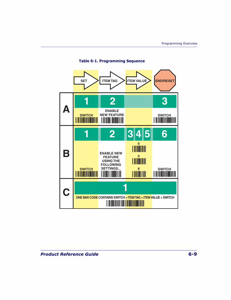
Programming Overview
Product Reference Guide 6-9
Table 6-1. Programming Sequence
1
1
C
A
B
2 3
1 2 3 4 5 6
SET
SWITCHENABLE
NEW FEATURE
ENABLE NEWFEATURE
USING THEFOLLOWINGSETTINGS...
SWITCH
SWITCH SWITCH
0
8
ITEM TAG ITEM VALUE END/RESET
0
ONE BAR CODE CONTAINS SWITCH + ITEM TAG + ITEM VALUE + SWITCH
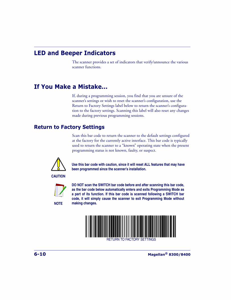
6-10 Magellan® 8300/8400
LED and Beeper IndicatorsThe scanner provides a set of indicators that verify/announce the various scanner functions.
If You Make a Mistake...If, during a programming session, you find that you are unsure of the scanner’s settings or wish to reset the scanner’s configuration, use the Return to Factory Settings label below to return the scanner’s configura-tion to the factory settings. Scanning this label will also reset any changes made during previous programming sessions.
Return to Factory SettingsScan this bar code to return the scanner to the default settings configured at the factory for the currently active interface. This bar code is typically used to return the scanner to a “known” operating state when the present programming status is not known, faulty, or suspect.
RETURN TO FACTORY SETTINGS
CAUTION
Use this bar code with caution, since it will reset ALL features that may havebeen programmed since the scanner’s installation.
NOTE
DO NOT scan the SWITCH bar code before and after scanning this bar code,as the bar code below automatically enters and exits Programming Mode asa part of its function. If this bar code is scanned following a SWITCH barcode, it will simply cause the scanner to exit Programming Mode withoutmaking changes.
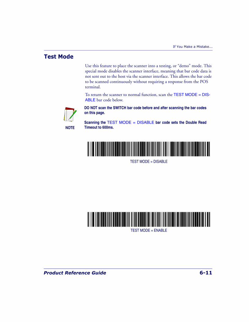
If You Make a Mistake...
Product Reference Guide 6-11
Test ModeUse this feature to place the scanner into a testing, or “demo” mode. This special mode disables the scanner interface, meaning that bar code data is not sent out to the host via the scanner interface. This allows the bar code to be scanned continuously without requiring a response from the POS terminal.
To return the scanner to normal function, scan the TEST MODE = DIS-ABLE bar code below.
TEST MODE = DISABLE
TEST MODE = ENABLE
NOTE
DO NOT scan the SWITCH bar code before and after scanning the bar codeson this page.
Scanning the TEST MODE = DISABLE bar code sets the Double ReadTimeout to 600ms.
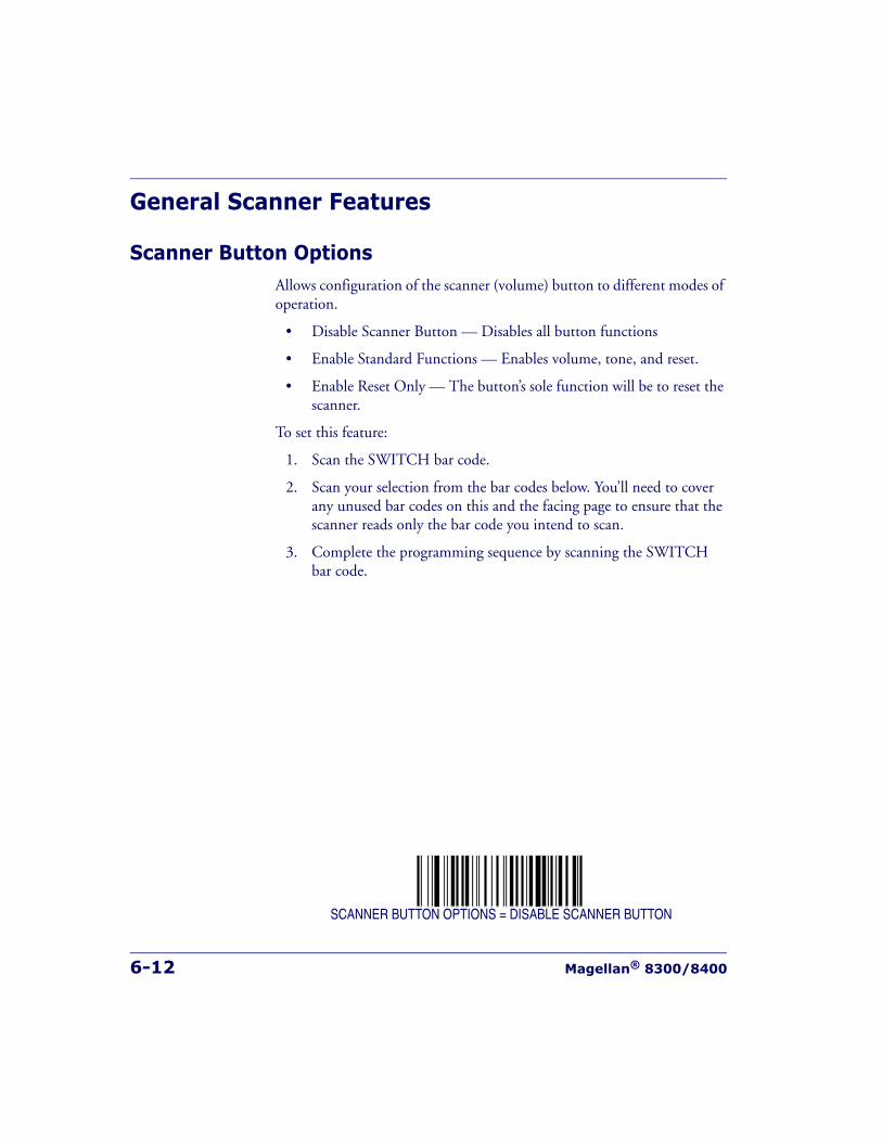
6-12 Magellan® 8300/8400
General Scanner Features
Scanner Button OptionsAllows configuration of the scanner (volume) button to different modes of operation.
• Disable Scanner Button — Disables all button functions
• Enable Standard Functions — Enables volume, tone, and reset.
• Enable Reset Only — The button’s sole function will be to reset the scanner.
To set this feature:
1. Scan the SWITCH bar code.
2. Scan your selection from the bar codes below. You’ll need to cover any unused bar codes on this and the facing page to ensure that the scanner reads only the bar code you intend to scan.
3. Complete the programming sequence by scanning the SWITCH bar code.
SCANNER BUTTON OPTIONS = DISABLE SCANNER BUTTON
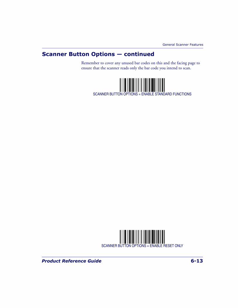
General Scanner Features
Product Reference Guide 6-13
Scanner Button Options — continuedRemember to cover any unused bar codes on this and the facing page to ensure that the scanner reads only the bar code you intend to scan.
SCANNER BUTTON OPTIONS = ENABLE STANDARD FUNCTIONS
SCANNER BUTTON OPTIONS = ENABLE RESET ONLY
6-14 Magellan® 8300/8400
Double Read TimeoutThe Double Read Timeout feature sets a time limit that determines how much time must pass before reading the same label again (e.g. two identi-cal items in succession).
To set the Double Read Timeout:
1. Scan the SWITCH bar code.
2. Scan your selection from the bar codes below. You’ll need to cover any unused bar codes on this and the facing page to ensure that the scanner reads only the bar code you intend to scan.
3. Complete the programming sequence by scanning the SWITCH bar code.
DOUBLE READ TIMEOUT = 400ms
DOUBLE READ TIMEOUT = 600ms
NOTE
If the incidence of multiple reads is not acceptable, increase the Double ReadTimeout setting to a higher value.
General Scanner Features
Product Reference Guide 6-15
Double Read Timeout — continuedRemember to cover any unused bar codes on this and the facing page to ensure that the scanner reads only the bar code you intend to scan.
DOUBLE READ TIMEOUT = 800ms
DOUBLE READ TIMEOUT = 1 SECOND
6-16 Magellan® 8300/8400
Laser TimeoutThe laser timeout feature sets the time for switching the visible laser diodes (VLDs) off if the scanner is idle. Using this feature can prolong the life of the VLDs.
To set the Laser Timeout:
1. Scan the SWITCH bar code.
2. Scan your selection from the bar codes below. You’ll need to cover any unused bar codes on this and the facing page to ensure that the scanner reads only the bar code you intend to scan.
3. Complete the programming sequence by scanning the SWITCH bar code.
LASER TIMEOUT = 5 MINUTES
General Scanner Features
Product Reference Guide 6-17
Laser Timeout — continuedRemember to cover any unused bar codes on this and the facing page to ensure that the scanner reads only the bar code you intend to scan.
LASER TIMEOUT = 10 MINUTES
LASER TIMEOUT = 15 MINUTES
6-18 Magellan® 8300/8400
Motor TimeoutThe Motor Timeout feature sets the time for automatically switching the motor off when the scanner is not in use.
To set the Motor Timeout:
1. Scan the SWITCH bar code.
2. Scan your selection from the bar codes below. You’ll need to cover any unused bar codes on this and the facing page to ensure that the scanner reads only the bar code you intend to scan.
3. Complete the programming sequence by scanning the SWITCH bar code.
MOTOR TIMEOUT = 5 MINUTES
NOTE
Laser safety requires that the laser switch off before the motor. If you set themotor timeout shorter than the laser timeout, the motor and the laser willboth shut off when the motor timeout expires.

General Scanner Features
Product Reference Guide 6-19
Motor Timeout — continuedRemember to cover any unused bar codes on this and the facing page to ensure that the scanner reads only the bar code you intend to scan.
MOTOR TIMEOUT = 10 MINUTES
MOTOR TIMEOUT = 15 MINUTES
6-20 Magellan® 8300/8400
Motor Timeout — continuedRemember to cover any unused bar codes on this and the facing page to ensure that the scanner reads only the bar code you intend to scan.
MOTOR TIMEOUT = 30 MINUTES
MOTOR TIMEOUT = 60 MINUTES
General Scanner Features
Product Reference Guide 6-21
Label Gone TimeoutSpecifies the amount of time that data segments are stored by the software before being discarded if a label has not been successfully decoded during the current “label in volume session,” which is defined as the time between when the label gone time is first started until the label gone timer expires.
To set the Label Gone Timeout:
1. Scan the SWITCH bar code.
2. Scan your selection from the bar codes below. You’ll need to cover any unused bar codes on this and the facing page to ensure that the scanner reads only the bar code you intend to scan.
3. Complete the programming sequence by scanning the SWITCH bar code.
LABEL GONE TIMEOUT = 50 mS

6-22 Magellan® 8300/8400
Label Gone Timeout — continuedRemember to cover any unused bar codes on this and the facing page to ensure that the scanner reads only the bar code you intend to scan.
LABEL GONE TIMEOUT = 160 mS
LABEL GONE TIMEOUT = 250 mS
General Scanner Features
Product Reference Guide 6-23
Label Gone Timeout — continuedRemember to cover any unused bar codes on this and the facing page to ensure that the scanner reads only the bar code you intend to scan.
LABEL GONE TIMEOUT = 500 mS
LABEL GONE TIMEOUT = 1 Second
6-24 Magellan® 8300/8400
Auxiliary Port ModeSelects the usage for the scanner’s optional auxilliary port. The choices listed below are mutually exclusive (only one option can be active at a time).
• Disabled — Port is inactive
• External Handheld Input — Supports Datalogic® handheld scan-ners (QuickScan 1000, QuickScan 6000, PowerScan) as well as other models such as the Symbol® HotShot. Call your dealer for more information about supported devices.
• PIR/CT — PIR (Productivity Index Reporting) is a value-added feature which allows the scanner to provide information to an exter-nal computer indicating how easy the label was to read. CT (Checker Training) is also a value-added feature which allows the scanner to provide feedback to the cashier on how to scan in a more ergonomic fashion
To set this feature:
1. Scan the SWITCH bar code.
2. Scan your selection from the bar codes below. You’ll need to cover any unused bar codes on this and the facing page to ensure that the scanner reads only the bar code you intend to scan.
3. Complete the programming sequence by scanning the SWITCH bar code.
AUXILIARY PORT MODE = DISABLE
NOTE
Cable pinout information for the Auxiliary Port is provided in Appendix B ofthis manual. A connected handheld scanner must be configured to transmitdata as outlined in Appendix G.
General Scanner Features
Product Reference Guide 6-25
Auxiliary Port Mode — continuedRemember to cover any unused bar codes on this and the facing page to ensure that the scanner reads only the bar code you intend to scan.
AUXILIARY PORT MODE = EXTERNAL HANDHELD INPUT
AUXILIARY PORT MODE = PIR/CT
6-26 Magellan® 8300/8400
Auxiliary Port Baud RateSpecifies the baud rate of the auxillary port when operating in PIR/CT mode.
To specify the Auxiliary Port Baud Rate:
1. Scan the SWITCH bar code.
2. Scan the desired baud rate from the bar codes below and on the immediately following pages. You’ll need to cover any unused bar codes on this and the facing page to ensure that the scanner reads only the bar code you intend to scan.
3. Complete the programming sequence by scanning the SWITCH bar code.
AUXILIARY PORT BAUD RATE = 1200
AUXILIARY PORT BAUD RATE = 2400
NOTE
PIR/CT is a value-added feature which may not have been activated on yourmodel.
General Scanner Features
Product Reference Guide 6-27
Auxiliary Port Baud Rate — continuedRemember to cover any unused bar codes on this and the facing page to ensure that the scanner reads only the bar code you intend to scan.
RS-232 BAUD RATE = 4800
RS-232 BAUD RATE = 9600
6-28 Magellan® 8300/8400
Auxiliary Port Baud Rate — continuedRemember to cover any unused bar codes on this and the facing page to ensure that the scanner reads only the bar code you intend to scan.
RS-232 BAUD RATE = 19200
RS-232 BAUD RATE = 38400
General Scanner Features
Product Reference Guide 6-29
Auxiliary Port Baud Rate — continuedRemember to cover any unused bar codes on this and the facing page to ensure that the scanner reads only the bar code you intend to scan.
RS-232 BAUD RATE = 57600
RS-232 BAUD RATE = 115200
6-30 Magellan® 8300/8400
Laser Failure ModeThis configuration item selects whether the scanner should continue oper-ating if only one laser is functional. (The scanner has two lasers: One for the horizontal window, and one for the vertical window.) Options for this feature are:
• Single Laser Failure OK — The scanner can still operate even if one laser is no longer functional. In this mode the scanner will read only from the window associated with the operational laser. This provides the user the ability to continue working until the unit is serviced. The 7-segment display will show the error code for the failed laser (reference Chapter 4, Error Codes), but the scanner will continue to function.
• Single Laser Failure Fatal — If it is desirable to have maximum per-formance or nothing at all, Laser Failure Mode should be selected as fatal. Upon single laser failure, the scanner will sound an error tone and cease scanning functions until serviced.
To set this feature:
1. Scan the SWITCH bar code.
2. Scan your selection from the bar codes below. You’ll need to cover any unused bar codes on this and the facing page to ensure that the scanner reads only the bar code you intend to scan.
3. Complete the programming sequence by scanning the SWITCH bar code.
LASER FAILURE MODE = SINGLE LASER FAILURE OK
LASER FAILURE MODE = SINGLE LASER FAILURE FATAL
General Scanner Features
Product Reference Guide 6-31
Productivity Index Reporting (PIR)/Cashier Training (CT)When PIR/CT is enabled, label quality data is appended to decoded data before being presented to the POS. The PIR feature allows the scanner to provide information to an external computer indicating how easy the label was to read. CT allows the scanner to provide feedback to the cashier on how to scan in a more ergonomic fashion.
To set this feature:
1. Scan the SWITCH bar code.
2. Scan your selection from the bar codes below. You’ll need to cover any unused bar codes on this and the facing page to ensure that the scanner reads only the bar code you intend to scan.
3. Complete the programming sequence by scanning the SWITCH bar code.
PIR/CT = DISABLE
PIR/CT = ENABLE
NOTE
This value-added feature is a factory-programmed option. Contact yourdealer for information about upgrading your system to include this advancedcapability.
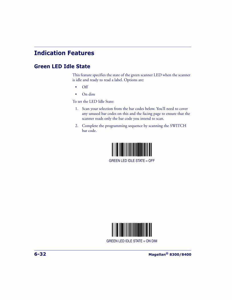
6-32 Magellan® 8300/8400
Indication Features
Green LED Idle StateThis feature specifies the state of the green scanner LED when the scanner is idle and ready to read a label. Options are:
• Off
• On dim
To set the LED Idle State:
1. Scan your selection from the bar codes below. You’ll need to cover any unused bar codes on this and the facing page to ensure that the scanner reads only the bar code you intend to scan.
2. Complete the programming sequence by scanning the SWITCH bar code.
GREEN LED IDLE STATE = OFF
GREEN LED IDLE STATE = ON DIM
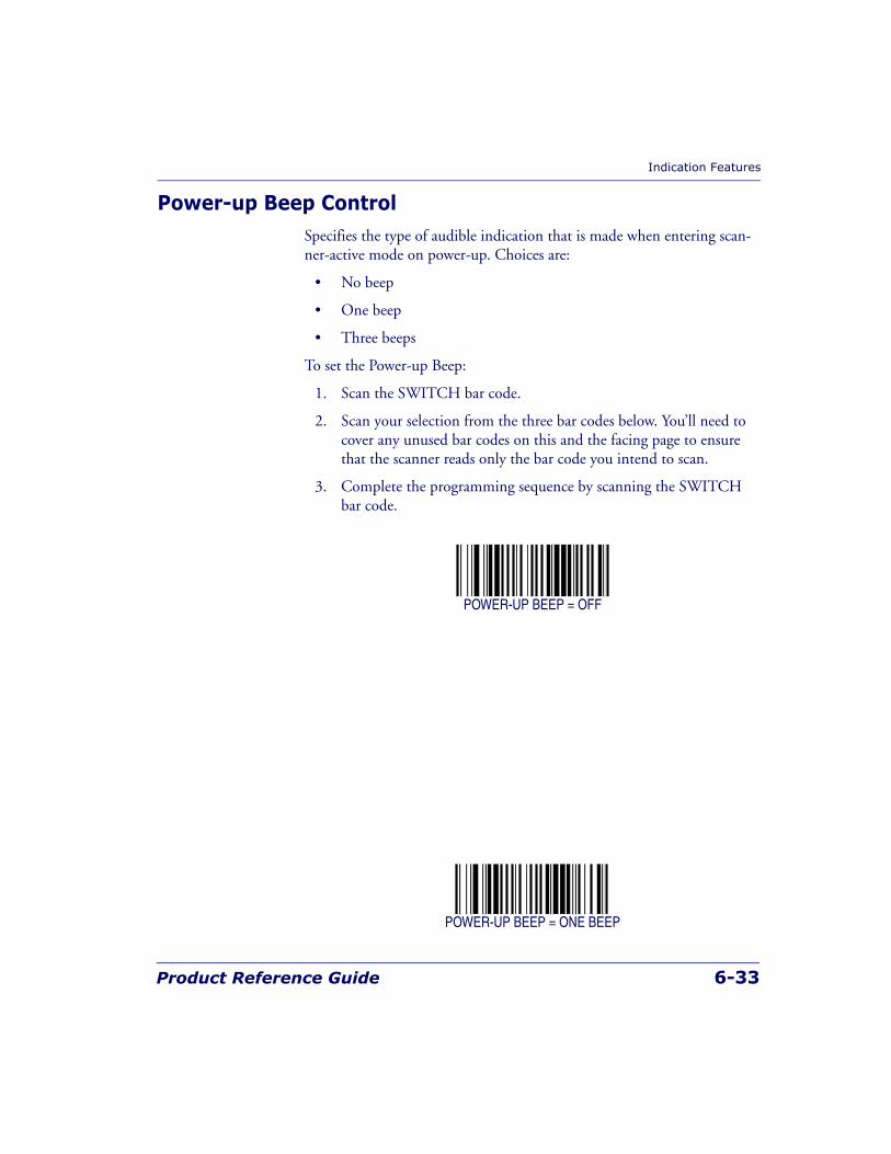
Indication Features
Product Reference Guide 6-33
Power-up Beep ControlSpecifies the type of audible indication that is made when entering scan-ner-active mode on power-up. Choices are:
• No beep
• One beep
• Three beeps
To set the Power-up Beep:
1. Scan the SWITCH bar code.
2. Scan your selection from the three bar codes below. You’ll need to cover any unused bar codes on this and the facing page to ensure that the scanner reads only the bar code you intend to scan.
3. Complete the programming sequence by scanning the SWITCH bar code.
POWER-UP BEEP = OFF
POWER-UP BEEP = ONE BEEP
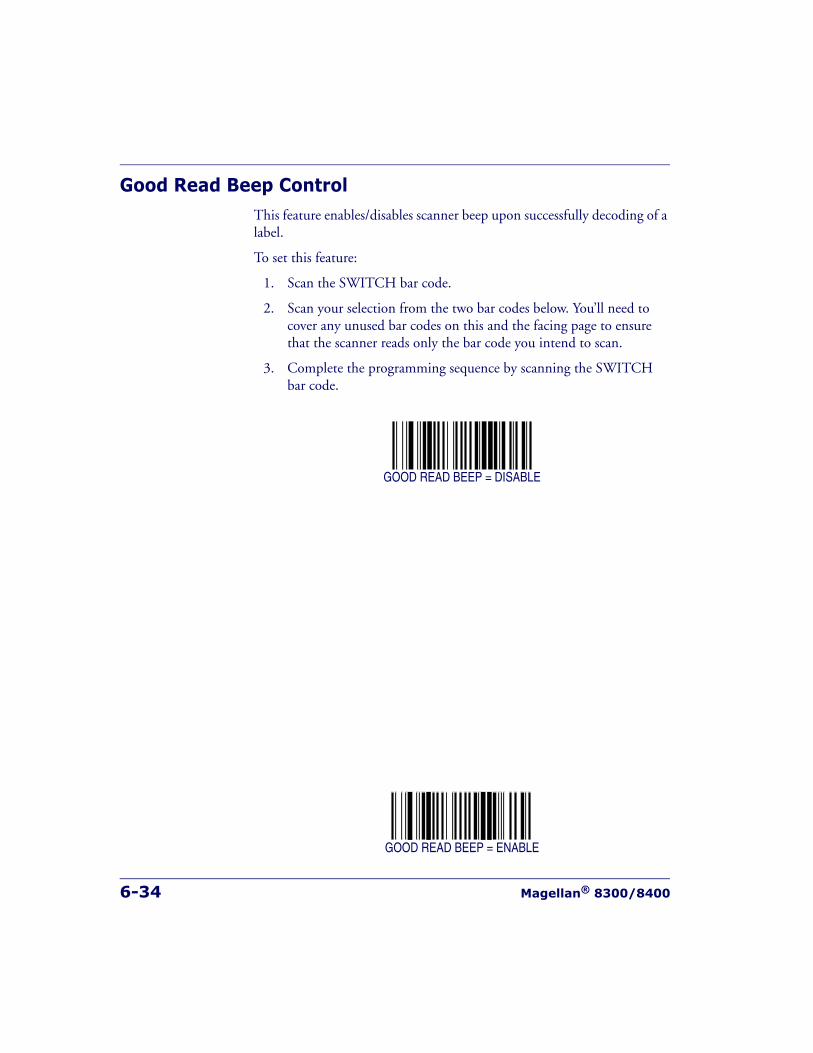
6-34 Magellan® 8300/8400
Good Read Beep ControlThis feature enables/disables scanner beep upon successfully decoding of a label.
To set this feature:
1. Scan the SWITCH bar code.
2. Scan your selection from the two bar codes below. You’ll need to cover any unused bar codes on this and the facing page to ensure that the scanner reads only the bar code you intend to scan.
3. Complete the programming sequence by scanning the SWITCH bar code.
GOOD READ BEEP = DISABLE
GOOD READ BEEP = ENABLE
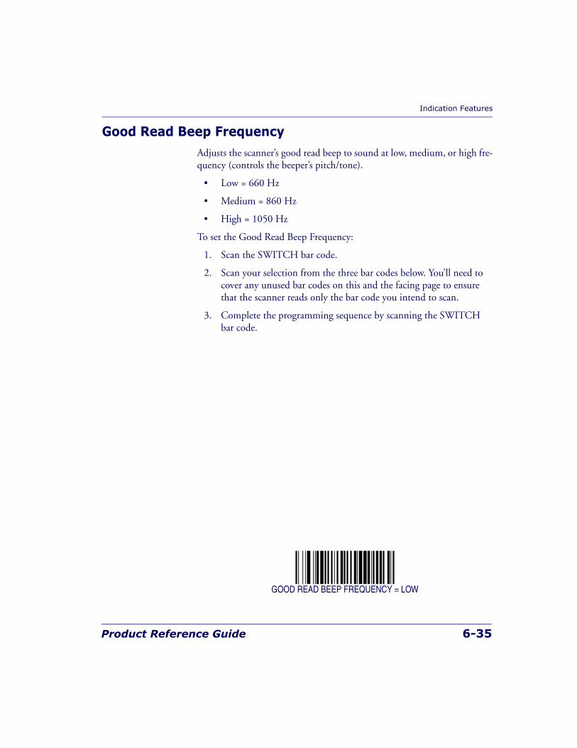
Indication Features
Product Reference Guide 6-35
Good Read Beep FrequencyAdjusts the scanner’s good read beep to sound at low, medium, or high fre-quency (controls the beeper’s pitch/tone).
• Low = 660 Hz
• Medium = 860 Hz
• High = 1050 Hz
To set the Good Read Beep Frequency:
1. Scan the SWITCH bar code.
2. Scan your selection from the three bar codes below. You’ll need to cover any unused bar codes on this and the facing page to ensure that the scanner reads only the bar code you intend to scan.
3. Complete the programming sequence by scanning the SWITCH bar code.
GOOD READ BEEP FREQUENCY = LOW
6-36 Magellan® 8300/8400
Good Read Beep Frequency — continuedRemember to cover any unused bar codes on this and the facing page to ensure that the scanner reads only the bar code you intend to scan.
GOOD READ BEEP FREQUENCY = MEDIUM
GOOD READ BEEP FREQUENCY = HIGH
Indication Features
Product Reference Guide 6-37
Good Read Beep LengthSpecifies the duration of a good read beep.
To set the good read beep length:
1. Scan the SWITCH bar code.
2. Scan the bar code, SET GOOD READ BEEP LENGTH. You’ll need to cover any unused bar codes on this and the facing page to ensure that the scanner reads only the bar code you intend to scan.
3. Scan the appropriate digits from the keypad in Appendix C that rep-resent the desired good read beep length setting. The selectable range is 1-255, which is the timeout in 10-millisecond increments. Pad all single and double digit numbers with leading zeroes to yield a three-digit entry (001-255).Examples:
001 = 10ms
005 = 50ms
040 = 400ms
250 = 2,500ms (2.5 seconds)
4. The scanner will automatically exit Programming Mode when the appropriate amount of digits have been scanned
SET GOOD READ BEEP LENGTH

6-38 Magellan® 8300/8400
Good Read Beep VolumeSelects the beeper volume upon a good read beep. There are five selectable volumes, with each volume increment adding approximately five decibels to the previous level:
• 0 = Lowest Volume
• 1 = Medium-Low Volume
• 2 = Medium Volume
• 3 = Highest Volume
To set the Good Read Beep Volume:
1. Scan the SWITCH bar code.
2. Scan your selected volume bar code from this or the following pages. You’ll need to cover any unused bar codes on this and the facing page to ensure that the scanner reads only the bar code you intend to scan.
3. Complete the programming sequence by scanning the SWITCH bar code.
GOOD READ BEEP VOLUME = LOWEST
Indication Features
Product Reference Guide 6-39
Good Read Beep Volume — continuedRemember to cover any unused bar codes on this and the facing page to ensure that the scanner reads only the bar code you intend to scan.
GOOD READ BEEP VOLUME = MEDIUM LOW
GOOD READ BEEP VOLUME = MEDIUM
6-40 Magellan® 8300/8400
Good Read Beep Volume — continuedRemember to cover any unused bar codes on this and the facing page to ensure that the scanner reads only the bar code you intend to scan.
GOOD READ BEEP VOLUME = HIGHEST
Indication Features
Product Reference Guide 6-41
Good Read When to IndicateThis feature specifies when the scanner will provide indication (beep and/or flash its green LED) upon successfully reading a bar code.
• Good Read = Indicate after decode
• Good Read = Indicate after transmit
• Good Read = Indicate after CTS goes inactive, then active
To set the Good Read When to Indicate feature:
1. Scan the SWITCH bar code.
2. Scan the desired mode bar code from this page. You’ll need to cover any unused bar codes on this and the facing page to ensure that the scanner reads only the bar code you intend to scan.
3. Complete the programming sequence by scanning the SWITCH bar code.
GOOD READ = INDICATE AFTER DECODE
NOTE
The “Indicate after CTS goes inactive...” mode applies to RS-232 STD and RS-232 WN interfaces only. If set to this mode in other interfaces, “Indicate afterdecode” mode will be implemented.
6-42 Magellan® 8300/8400
Good Read When to Indicate — continuedRemember to cover any unused bar codes on this and the facing page to ensure that the scanner reads only the bar code you intend to scan.
GOOD READ = INDICATE AFTER TRANSMIT
GOOD READ = INDICATE AFTER CTS GOES INACTIVE, THEN ACTIVE(RS-232 ONLY)
Scale Features
Product Reference Guide 6-43
Scale Features
Scale EnableUse this feature to enable or disable scale operation.
To set this feature:
1. Scan the SWITCH bar code.
2. Scan your selection from the two bar codes below. You’ll need to cover any unused bar codes on this and the facing page to ensure that the scanner reads only the bar code you intend to scan.
3. Complete the programming sequence by scanning the SWITCH bar code.
SCALE = DISABLE
SCALE = ENABLE
NOTE
Recalibration/recertification may be required when adding scale functional-ity. Consult your local Weights and Measures authority.
If this feature is enabled the scanner will expect that it is to function as ascanner-scale, and will indicate an error if it is not a scale-equipped unit. SeeChapter 4, Error Codes, for more information.
6-44 Magellan® 8300/8400
Scale Country ModeWhen a weight is presented, the scanner/scale will apply the country-spe-cific weighing rules specified via this feature.
SCALE COUNTRY MODE = U.S.A.
SCALE COUNTRY MODE = U.K.
NOTE
Scale Country Mode applies only when a scale is enabled.
RS-232 SASI scale interface supports only U.S.A. mode.
Scale Features
Product Reference Guide 6-45
Scale Country Mode — continuedRemember to cover any unused bar codes on this and the facing page to ensure that the scanner reads only the bar code you intend to scan.
SCALE COUNTRY MODE = AUSTRALIA
6-46 Magellan® 8300/8400
Scale Enforced Zero ReturnThis feature enables/disables the enforced zero return of the scale. Three settings are available for this feature:
• Disable
• Scale Must Return to Zero Weight Within Two Minutes — Scale will require re-zeroing if a non-zero weight is left on for more than two minutes or if the scale is below zero.
• Scale Must Return to Zero Weight Between Weight Requests — Re-zeroing is required if weight doesn't return to zero between weight requests from the POS, plus scale will require re-zeroing if a non-zero weight is left on for more than two minutes or if the scale is below zero.
• Non-Zero for Two Minutes — Re-zeroing is required if weight does not return to zero within two minutes.
To set this feature:
1. Scan the SWITCH bar code.
2. Scan your selection from the bar codes below. You’ll need to cover any unused bar codes on this and the facing page to ensure that the scanner reads only the bar code you intend to scan. The strategy is to select the lowest possible filter level needed that allows normal scale operation.
3. Complete the programming sequence by scanning the SWITCH bar code.
SCALE ENFORCED ZERO RETURN = DISABLE
Scale Features
Product Reference Guide 6-47
Scale Enforced Zero Return — continuedRemember to cover any unused bar codes on this and the facing page to ensure that the scanner reads only the bar code you intend to scan.
SCALE ENFORCED ZERO RETURN =NON-ZERO FOR 2 MINUTES OR BELOW ZERO
SCALE ENFORCED ZERO RETURN = NON-ZERO FOR 2 MINUTES OR BELOW ZERO OR NO ZERO BETWEEN WEIGHTS

6-48 Magellan® 8300/8400
Scale Enforced Zero Return — continuedRemember to cover any unused bar codes on this and the facing page to ensure that the scanner reads only the bar code you intend to scan.
SCALE ENFORCED ZERO RETURN =NON-ZERO FOR 2 MINUTES
Scale Features
Product Reference Guide 6-49
Scale Interface TypeUse this feature to select the scale interface type. Choices are:
• No Scale Interface
• RS-232 — SASI
• RS-232 — ICL
To set the Scale Interface Type:
1. Scan the SWITCH bar code.
2. Scan your selection from the bar codes below. You’ll need to cover any unused bar codes on this and the facing page to ensure that the scanner reads only the bar code you intend to scan.
3. Complete the programming sequence by scanning the SWITCH bar code.
SCALE INTERFACE TYPE = NO SCALE INTERFACE
SCALE INTERFACE TYPE = RS-232 — SASI
6-50 Magellan® 8300/8400
Scale Interface Type — continuedRemember to cover any unused bar codes on this and the facing page to ensure that the scanner reads only the bar code you intend to scan.
SCALE INTERFACE TYPE = RS-232 — ICL
Scale Features
Product Reference Guide 6-51
Scale Motion Level FilterIn environments where checkstands generate excessive vibration, the scale can be set to filter a certain amount of the motion with regard to its oper-ation.
To set this feature:
1. Scan the SWITCH bar code.
2. Scan your selection from the bar codes below. You’ll need to cover any unused bar codes on this and the facing page to ensure that the scanner reads only the bar code you intend to scan. The strategy is to select the lowest possible filter level needed that allows normal scale operation.
3. Complete the programming sequence by scanning the SWITCH bar code.
SCALE MOTION LEVEL FILTER = LOW
SCALE MOTION LEVEL FILTER = MEDIUM LOW
NOTE
This filter is generally used only in applications where scale error E_1 (toomuch motion at power-up) has occurred.
6-52 Magellan® 8300/8400
Scale Motion Level Filter — continuedRemember to cover any unused bar codes on this and the facing page to ensure that the scanner reads only the bar code you intend to scan.
SCALE MOTION LEVEL FILTER = MEDIUM HIGH
SCALE MOTION LEVEL FILTER = HIGH
Scale Features
Product Reference Guide 6-53
Scale Warm-up TimeSpecifies the amount of time after entering scale warm-up mode before the scale enters scale-active mode.
To set this feature:
1. Scan the SWITCH bar code.
2. Scan your selection from the bar codes below.
3. You’ll need to cover any unused bar codes on this and the facing page to ensure that the scanner reads only the bar code you intend to scan.
4. Complete the programming sequence by scanning the SWITCH bar code.
SCALE WARM-UP TIME = NO WARM-UP
SCALE WARM-UP TIME = 5 SECONDS
NOTE
Applies only when Scale Enable is enabled.
6-54 Magellan® 8300/8400
Scale Warm-up Time — continuedRemember to cover any unused bar codes on this and the facing page to ensure that the scanner reads only the bar code you intend to scan.
SCALE WARM-UP TIME = 10 SECONDS
SCALE WARM-UP TIME = 15 SECONDS
Scale Features
Product Reference Guide 6-55
Scale LED EnableThis feature enables/disables Scale LED (Yellow LED) operation.
To set this feature:
1. Scan the SWITCH bar code.
2. Scan your selection from the two bar codes below. You’ll need to cover any unused bar codes on this and the facing page to ensure that the scanner reads only the bar code you intend to scan.
3. Complete the programming sequence by scanning the SWITCH bar code.
SCALE LED = DISABLE
SCALE LED = ENABLE
6-56 Magellan® 8300/8400
Scale Diagnostics Mode EnableEnables/disables the ability for the operator to initiate scale diagnostics.
To set this feature:
1. Scan the SWITCH bar code.
2. Scan your selection from the two bar codes below. You’ll need to cover any unused bar codes on this and the facing page to ensure that the scanner reads only the bar code you intend to scan.
3. Complete the programming sequence by scanning the SWITCH bar code.
SCALE DIAGNOSTICS MODE = DISABLE
SCALE DIAGNOSTICS MODE = ENABLE

Scale Features
Product Reference Guide 6-57
Scale Calibration NotificationWhen enabled, this feature allows the host to be notified of a calibration event.
To set this feature:
1. Scan the SWITCH bar code.
2. Scan your selection from the two bar codes below. You’ll need to cover any unused bar codes on this and the facing page to ensure that the scanner reads only the bar code you intend to scan.
3. Complete the programming sequence by scanning the SWITCH bar code.
SCALE CALIBRATION NOTIFICATION = DISABLE
SCALE CALIBRATION NOTIFICATION = ENABLE
6-58 Magellan® 8300/8400
Scale Intercharacter DelaySets the delay between the end of one character and the beginning of the next, in 10 millisecond increments.
To specify the intercharacter delay:
1. Scan the SWITCH bar code.
2. Scan the bar code below, SET KEYBOARD WEDGE INTERCHAR-ACTER DELAY. You’ll need to cover any unused bar codes on this and the facing page to ensure that the scanner reads only the bar code you intend to scan.
3. Scan the appropriate digits from the keypad in Appendix C that rep-resent the desired delay. The selectable range is 0-100, which is the delay in 10-millisecond increments. Pad all single and double digit numbers with leading zeroes to yield a three-digit entry (000-100).Examples:
001 = 10ms
005 = 50ms
040 = 400ms
100 = 1,000ms (1 second)
4. The scanner will automatically exit Programming Mode when the appropriate amount of digits have been scanned.
SCALE INTERCHARACTER DELAY
Scale Features
Product Reference Guide 6-59
Remote Display — Enable/DisableThe scanner-scale can be configured to operate with or without a Remote Display.
REMOTE DISPLAY = DISABLE
REMOTE DISPLAY = ENABLE
NOTE
Recalibration/recertification may be required when adding a Remote Display.Consult your local Weights and Measures authority.
If this feature is enabled the scanner-scale will expect that it is connected toa Remote Display, and will indicate an error if one is not. See Chapter 4,Error Codes, for more information.
6-60 Magellan® 8300/8400
EAS Features
EAS Active StateSpecifies the active state polarity of EAS (Electronic Article Survellance); the inactive state is its opposite polarity. EAS output goes active during the good read indication of a bar code, allowing the EAS device to deactivate a tag on the product.
To set the EAS Active State:
1. Scan the SWITCH bar code.
2. Scan your selection from the bar codes below. You’ll need to cover any unused bar codes on this and the facing page to ensure that the scanner reads only the bar code you intend to scan.
3. Complete the programming sequence by scanning the SWITCH bar code.
EAS ACTIVE STATE = ACTIVE LOW
EAS ACTIVE STATE = ACTIVE HIGH
EAS Features
Product Reference Guide 6-61
EAS TimeoutSpecifies the amount of time that an EAS (Electronic Article Survellance) signal is held in its active state for a good read indication.
To set the EAS Timeout:
1. Scan the SWITCH bar code.
2. Scan the bar code, SET EAS TIMEOUT below. You’ll need to cover any unused bar codes on this and the facing page to ensure that the scanner reads only the bar code you intend to scan.
3. Scan the appropriate digits from the keypad in Appendix C thatrepresent the desired EAS Timeout duration. The selectable range is 0-255, which is the timeout in 10-millisecond increments. Pad all single and double digit numbers with leading zeroes to yield a three-digit entry (000-255).Examples:
000 = EAS timeout disabled
001 = 10ms
005 = 50ms
040 = 400ms
250 = 2,500ms (2.5 seconds)
4. Scan the SWITCH bar code to exit Programming Mode.
SET EAS TIMEOUT
NOTE
A setting of 0 (000) disables this feature.
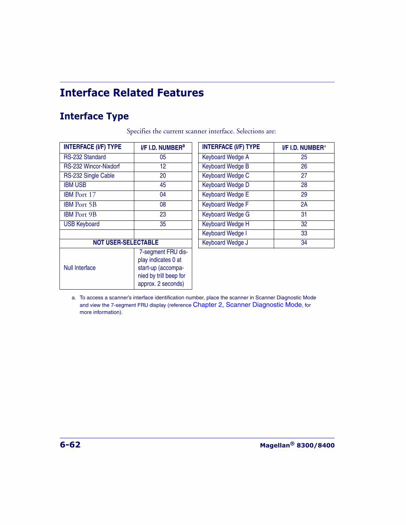
6-62 Magellan® 8300/8400
Interface Related Features
Interface TypeSpecifies the current scanner interface. Selections are:
INTERFACE (I/F) TYPE I/F I.D. NUMBERa
a. To access a scanner’s interface identification number, place the scanner in Scanner Diagnostic Mode and view the 7-segment FRU display (reference Chapter 2, Scanner Diagnostic Mode, for more information).
INTERFACE (I/F) TYPE I/F I.D. NUMBERa
RS-232 Standard 05 Keyboard Wedge A 25RS-232 Wincor-Nixdorf 12 Keyboard Wedge B 26RS-232 Single Cable 20 Keyboard Wedge C 27IBM USB 45 Keyboard Wedge D 28
IBM Port 17 04 Keyboard Wedge E 29
IBM Port 5B 08 Keyboard Wedge F 2A
IBM Port 9B 23 Keyboard Wedge G 31
USB Keyboard 35 Keyboard Wedge H 32Keyboard Wedge I 33
NOT USER-SELECTABLE Keyboard Wedge J 34
Null Interface
7-segment FRU dis-play indicates 0 at start-up (accompa-nied by trill beep for approx. 2 seconds)
Interface Related Features
Product Reference Guide 6-63
Interface Type — continued
To select the desired interface:
1. Disconnect current interface cable(s) if currently connected.
2. Scan the SWITCH bar code
3. Scan the bar code representing the appropriate interface located on the following pages. You’ll need to cover any unused bar codes adja-cent to and on any facing pages to ensure the scanner reads only the bar code you intend to scan.
NOTE
A new scanner may have been shipped from the factory with a Null Interface(no interface type selected) to ensure system compatibility at installation. Inthis case, the correct Interface Type programming bar code must be scannedfirst before the scanner can be used with a POS system.
NOTE
If the scanner’s interface type must be changed, always be sure that interfaceconfiguration is the FIRST item scanned during a programming session.(Selecting an interface type resets ALL other configuration items to the fac-tory default for that interface type.)
CAUTION
Great care should be taken to select the correct interface type, since you cancause damage to the scanner and/or POS terminal by attempting to changeto an incompatible interface. ALWAYS make interface selections with thehost cable DISCONNECTED.
NOTE
When an interface is selected, the scanner loads the factory configurationfor that interface as the selection is made, erasing any and all custom config-uration that may have previously been done.
6-64 Magellan® 8300/8400
Interface Type — continued4. Complete the programming sequence by scanning the SWITCH
bar code.
5. Connect new interface cable(s).
NOTE
Once the correct interface has been set, it will be necessary to proceed tothe appropriate pages in this manual that select parameters and options forthat interface. For example, if RS-232 is selected, turn to the pages in thismanual headed as features specific to the RS-232 interface.
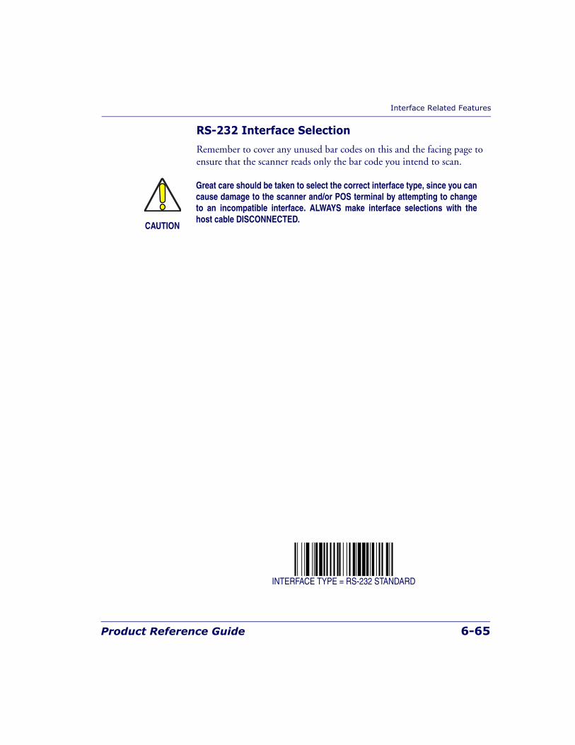
Interface Related Features
Product Reference Guide 6-65
RS-232 Interface Selection
Remember to cover any unused bar codes on this and the facing page to ensure that the scanner reads only the bar code you intend to scan.
INTERFACE TYPE = RS-232 STANDARD
CAUTION
Great care should be taken to select the correct interface type, since you cancause damage to the scanner and/or POS terminal by attempting to changeto an incompatible interface. ALWAYS make interface selections with thehost cable DISCONNECTED.
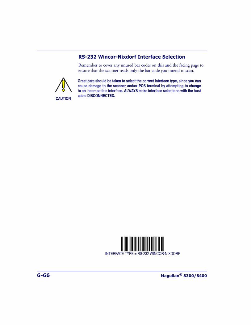
6-66 Magellan® 8300/8400
RS-232 Wincor-Nixdorf Interface Selection
Remember to cover any unused bar codes on this and the facing page to ensure that the scanner reads only the bar code you intend to scan.
INTERFACE TYPE = RS-232 WINCOR-NIXDORF
CAUTION
Great care should be taken to select the correct interface type, since you cancause damage to the scanner and/or POS terminal by attempting to changeto an incompatible interface. ALWAYS make interface selections with the hostcable DISCONNECTED.
Interface Related Features
Product Reference Guide 6-67
RS-232 Single Cable Interface Selection
Remember to cover any unused bar codes on this and the facing page to ensure that the scanner reads only the bar code you intend to scan.
INTERFACE TYPE = RS-232 SINGLE CABLE
CAUTION
Great care should be taken to select the correct interface type, since you cancause damage to the scanner and/or POS terminal by attempting to changeto an incompatible interface. ALWAYS make interface selections with the hostcable DISCONNECTED.
NOTE
Single cable installations require connection at the POS Terminal (host) port.The Scale Host port connection is not used for this interface.
6-68 Magellan® 8300/8400
IBM USB Interface Selection
Remember to cover any unused bar codes on this and the facing page to ensure that the scanner reads only the bar code you intend to scan.
INTERFACE TYPE = IBM USB
CAUTION
Great care should be taken to select the correct interface type, since you cancause damage to the scanner and/or POS terminal by attempting to change toan incompatible interface. ALWAYS make interface selections with the hostcable DISCONNECTED.
NOTE
Single cable installations require connection at the POS Terminal (host) port.The Scale Host port connection is not used for this interface.
Interface Related Features
Product Reference Guide 6-69
IBM Port 17 Interface Selection
Remember to cover any unused bar codes on this and the facing page to ensure that the scanner reads only the bar code you intend to scan.
INTERFACE TYPE = IBM PORT 17
CAUTION
Great care should be taken to select the correct interface type, since you cancause damage to the scanner and/or POS terminal by attempting to changeto an incompatible interface. ALWAYS make interface selections with the hostcable DISCONNECTED.
NOTE
Single cable installations require connection at the POS Terminal (host) port.The Scale Host port connection is not used for this interface.
6-70 Magellan® 8300/8400
IBM Port 5B Interface Selection
Remember to cover any unused bar codes on this and the facing page to ensure that the scanner reads only the bar code you intend to scan.
INTERFACE TYPE = IBM PORT 5B
CAUTION
Great care should be taken to select the correct interface type, since you cancause damage to the scanner and/or POS terminal by attempting to changeto an incompatible interface. ALWAYS make interface selections with the hostcable DISCONNECTED.
Interface Related Features
Product Reference Guide 6-71
IBM Port 9B Interface Selection
Remember to cover any unused bar codes on this and the facing page to ensure that the scanner reads only the bar code you intend to scan.
INTERFACE TYPE = IBM PORT 9B
CAUTION
Great care should be taken to select the correct interface type, since you cancause damage to the scanner and/or POS terminal by attempting to changeto an incompatible interface. ALWAYS make interface selections with the hostcable DISCONNECTED.
6-72 Magellan® 8300/8400
USB Keyboard Interface Selection
Remember to cover any unused bar codes on this and the facing page to ensure that the scanner reads only the bar code you intend to scan.
INTERFACE TYPE = USB KEYBOARD
CAUTION
Great care should be taken to select the correct interface type, since you cancause damage to the scanner and/or POS terminal by attempting to changeto an incompatible interface. ALWAYS make interface selections with the hostcable DISCONNECTED.

Interface Related Features
Product Reference Guide 6-73
Keyboard Wedge A Interface Selection
Remember to cover any unused bar codes on this and the facing page to ensure that the scanner reads only the bar code you intend to scan.
INTERFACE TYPE = KEYBOARD WEDGE A
CAUTION
Great care should be taken to select the correct interface type, since you cancause damage to the scanner and/or POS terminal by attempting to changeto an incompatible interface. ALWAYS make interface selections with the hostcable DISCONNECTED.
6-74 Magellan® 8300/8400
Keyboard Wedge B Interface Selection
Remember to cover any unused bar codes on this and the facing page to ensure that the scanner reads only the bar code you intend to scan.
INTERFACE TYPE = KEYBOARD WEDGE B
CAUTION
Great care should be taken to select the correct interface type, since you cancause damage to the scanner and/or POS terminal by attempting to changeto an incompatible interface. ALWAYS make interface selections with the hostcable DISCONNECTED.

Interface Related Features
Product Reference Guide 6-75
Keyboard Wedge C Interface Selection
Remember to cover any unused bar codes on this and the facing page to ensure that the scanner reads only the bar code you intend to scan.
INTERFACE TYPE = KEYBOARD WEDGE C
CAUTION
Great care should be taken to select the correct interface type, since you cancause damage to the scanner and/or POS terminal by attempting to changeto an incompatible interface. ALWAYS make interface selections with the hostcable DISCONNECTED.
6-76 Magellan® 8300/8400
Keyboard Wedge D Interface Selection
Remember to cover any unused bar codes on this and the facing page to ensure that the scanner reads only the bar code you intend to scan.
INTERFACE TYPE = KEYBOARD WEDGE D
CAUTION
Great care should be taken to select the correct interface type, since you cancause damage to the scanner and/or POS terminal by attempting to changeto an incompatible interface. ALWAYS make interface selections with the hostcable DISCONNECTED.
Interface Related Features
Product Reference Guide 6-77
Keyboard Wedge E Interface Selection
Remember to cover any unused bar codes on this and the facing page to ensure that the scanner reads only the bar code you intend to scan.
INTERFACE TYPE = KEYBOARD WEDGE E
CAUTION
Great care should be taken to select the correct interface type, since you cancause damage to the scanner and/or POS terminal by attempting to changeto an incompatible interface. ALWAYS make interface selections with the hostcable DISCONNECTED.

6-78 Magellan® 8300/8400
Keyboard Wedge F Interface Selection
Remember to cover any unused bar codes on this and the facing page to ensure that the scanner reads only the bar code you intend to scan.
INTERFACE TYPE = KEYBOARD WEDGE F
CAUTION
Great care should be taken to select the correct interface type, since you cancause damage to the scanner and/or POS terminal by attempting to changeto an incompatible interface. ALWAYS make interface selections with the hostcable DISCONNECTED.

Interface Related Features
Product Reference Guide 6-79
Keyboard Wedge G Interface Selection
Remember to cover any unused bar codes on this and the facing page to ensure that the scanner reads only the bar code you intend to scan.
INTERFACE TYPE = KEYBOARD WEDGE G
CAUTION
Great care should be taken to select the correct interface type, since you cancause damage to the scanner and/or POS terminal by attempting to changeto an incompatible interface. ALWAYS make interface selections with the hostcable DISCONNECTED.
6-80 Magellan® 8300/8400
Keyboard Wedge H Interface Selection
Remember to cover any unused bar codes on this and the facing page to ensure that the scanner reads only the bar code you intend to scan.
INTERFACE TYPE = KEYBOARD WEDGE H
CAUTION
Great care should be taken to select the correct interface type, since you cancause damage to the scanner and/or POS terminal by attempting to changeto an incompatible interface. ALWAYS make interface selections with the hostcable DISCONNECTED.
Interface Related Features
Product Reference Guide 6-81
Keyboard Wedge I Interface Selection
Remember to cover any unused bar codes on this and the facing page to ensure that the scanner reads only the bar code you intend to scan.
INTERFACE TYPE = KEYBOARD WEDGE I
CAUTION
Great care should be taken to select the correct interface type, since you cancause damage to the scanner and/or POS terminal by attempting to changeto an incompatible interface. ALWAYS make interface selections with the hostcable DISCONNECTED.
6-82 Magellan® 8300/8400
Keyboard Wedge J Interface Selection
Remember to cover any unused bar codes on this and the facing page to ensure that the scanner reads only the bar code you intend to scan.
INTERFACE TYPE = KEYBOARD WEDGE J
CAUTION
Great care should be taken to select the correct interface type, since you cancause damage to the scanner and/or POS terminal by attempting to changeto an incompatible interface. ALWAYS make interface selections with the hostcable DISCONNECTED.
Interface Related Features
Product Reference Guide 6-83
Maximum Host-Transmitted Message Length
Specifies the maximum number of data characters allowed in messages transmitted to the host.
To set the Maximum Host-Transmitted Message Length:
1. Scan the SWITCH bar code.
2. Scan the bar code, SET MAXIMUM HOST-TRANSMITTED MES-SAGE LENGTH below. You’ll need to cover any unused bar codes on this and the facing page to ensure that the scanner reads only the bar code you intend to scan.
3. Scan the appropriate digits from the keypad in Appendix C that rep-resent the desired maximum host-transmitted message length. The selectable range is 0-249 data characters. (Labels that are longer than this length are not read.) Pad all single and double digit numbers with leading zeroes to yield a three-digit entry (000-249).
4. The scanner will automatically exit Programming Mode when the appropriate amount of digits have been scanned
SET MAXIMUM HOST-TRANSMITTED MESSAGE LENGTH
NOTE
If this configuration item is set to 0 (000), there is no general length limitimposed on data being transmitted to the host.
6-84 Magellan® 8300/8400
Number of Host Transmission BuffersSpecifies the number of host transmission(s) that may be buffered. By buffering data from a bar code, the scanner can continue to read a new bar code while the old one is being transmitted to the host. Selecting BUFF-ERS = 1 means that the first bar code must be transmitted before a new one can be read. A selection of BUFFERS = 2 means that a new bar code can be read while data from the first bar code is transmitted. When the feature, Good Read Beep Control, is enabled, the scanner will beep when the data is placed in a transmission buffer.
When a DISABLE SCANNER command is received from the host, the scanner will continue to transmit all data that is buffered.
To select the Number of Host Transmission Buffers:
1. Scan the SWITCH bar code.
2. Scan bar code below representing the desired setting. You’ll need to cover any unused bar codes on this and the facing page to ensure that the scanner reads only the bar code you intend to scan.
3. Complete the programming sequence by scanning the SWITCH bar code.
NUMBER OF HOST TRANSMISSION BUFFERS = 1
NUMBER OF HOST TRANSMISSION BUFFERS = 2
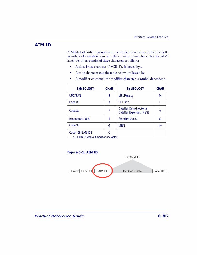
Interface Related Features
Product Reference Guide 6-85
AIM IDAIM label identifiers (as opposed to custom characters you select yourself as with label identifiers) can be included with scanned bar code data. AIM label identifiers consist of three characters as follows:
• A close brace character (ASCII ‘]’), followed by...
• A code character (see the table below), followed by
• A modifier character (the modifier character is symbol dependent)
Figure 6-1. AIM ID
SYMBOLOGY CHAR SYMBOLOGY CHAR
UPC/EAN E MSI/Plessey M
Code 39 A PDF 417 L
Codabar FDataBar Omnidirectional, DataBar Expanded (RSS)
e
Interleaved.2 of 5 I Standard 2 of 5 S
Code 93 G ISBN Xa
a. ISBN (X with a 0 modifier character)
Code 128/EAN 128 C
Prefix Label ID Label IDBar Code DataAIM ID
SCANNER
6-86 Magellan® 8300/8400
AIM ID — continuedRemember to cover any unused bar codes on this and the facing page to ensure that the scanner reads only the bar code you intend to scan.
AIM ID: DISABLE
AIM ID: ENABLE
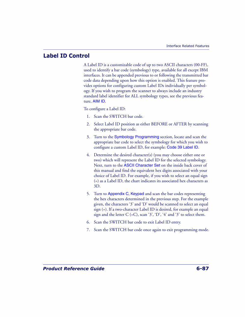
Interface Related Features
Product Reference Guide 6-87
Label ID ControlA Label ID is a customizable code of up to two ASCII characters (00-FF), used to identify a bar code (symbology) type, available for all except IBM interfaces. It can be appended previous to or following the transmitted bar code data depending upon how this option is enabled. This feature pro-vides options for configuring custom Label IDs individually per symbol-ogy. If you wish to program the scanner to always include an industry standard label identifier for ALL symbology types, see the previous fea-ture, AIM ID.
To configure a Label ID:
1. Scan the SWITCH bar code.
2. Select Label ID position as either BEFORE or AFTER by scanning the appropriate bar code.
3. Turn to the Symbology Programming section, locate and scan the appropriate bar code to select the symbology for which you wish to configure a custom Label ID, for example: Code 39 Label ID.
4. Determine the desired character(s) (you may choose either one or two) which will represent the Label ID for the selected symbology. Next, turn to the ASCII Character Set on the inside back cover of this manual and find the equivalent hex digits associated with your choice of Label ID. For example, if you wish to select an equal sign (=) as a Label ID, the chart indicates its associated hex characters as 3D.
5. Turn to Appendix C, Keypad and scan the bar codes representing the hex characters determined in the previous step. For the example given, the characters ‘3’ and ‘D’ would be scanned to select an equal sign (=). If a two-character Label ID is desired, for example an equal sign and the letter C (=C), scan ‘3’, ‘D’, ‘4’ and ‘3’ to select them.
6. Scan the SWITCH bar code to exit Label ID entry.
7. Scan the SWITCH bar code once again to exit programming mode.
6-88 Magellan® 8300/8400
Figure 6-2. Label ID Position Options
Label ID Control — continuedRemember to cover any unused bar codes on this and the facing page to ensure that the scanner reads only the bar code you intend to scan.
LABEL ID TRANSMISSION: DISABLE
LABEL ID TRANSMISSION: BEFORE BAR CODE DATA
OR
Prefix Suffix
SCANNER
Label ID Label IDBar Code DataAim ID
Interface Related Features
Product Reference Guide 6-89
Label ID Control — continuedRemember to cover any unused bar codes on this and the facing page to ensure that the scanner reads only the bar code you intend to scan.
LABEL ID TRANSMISSION: AFTER BAR CODE DATA

6-90 Magellan® 8300/8400
Global PrefixThis feature specifies the prefix that is added to beginning of label trans-mission.
To specify the Global Prefix Character(s):
1. Scan the SWITCH bar code.
2. Scan the bar code, SET GLOBAL PREFIX below. You’ll need to cover any unused bar codes to ensure the scanner reads only the bar code you intend to scan.
3. Scan the appropriate characters/digits from the keypad in AppendixC that represent the hex designation for the desired character(s). A table containing the ASCII Character Set and their corresponding Hex Values is available in the inside back cover of this manual. ASCII parameters must be input by scanning a pair of hexadecimal digits for each character. Thus, to set a two-character value of AB, bar codes containing the digits ‘4’, ‘1’, ‘4’, and ‘2’ must be scanned. The selectable range for this option is any hex value from 00 to FF. Up to 20 hex pairs can be designated.
4. If designating the full 20 hex pairs, the scanner will automatically exit Programming Mode when the appropriate amount of digits have been scanned. If designating less than 20 hex pairs, you can end the programming sequence early by scanning the TERMINATE SEQUENCE bar code.
5. Complete the programming sequence by scanning the SWITCH bar code.
NOTE
To specify “no Global Prefix,” scan 00.
Interface Related Features
Product Reference Guide 6-91
Global Prefix — continuedRemember to cover any unused bar codes on this and the facing page to ensure that the scanner reads only the bar code you intend to scan.
SET GLOBAL PREFIX
TERMINATE SEQUENCE

6-92 Magellan® 8300/8400
Global SuffixThis feature specifies the suffix that is added to end of a label transmis-sion. Three standard options are available below. Contact your dealer for other alternate settings for this feature.
• No Global Suffix
• CR — Carriage Return
• CR LF — Carriage Return, Line Feed
To set the Global Suffix:
1. Scan the SWITCH bar code.
2. Scan your selection from the bar codes below.
3. Complete the programming sequence by scanning the SWITCH bar code.
GLOBAL SUFFIX = NO GLOBAL SUFFIX
Interface Related Features
Product Reference Guide 6-93
Global Suffix — continuedRemember to cover any unused bar codes on this and the facing page to ensure that the scanner reads only the bar code you intend to scan.
GLOBAL SUFFIX = CR
GLOBAL SUFFIX = CR LF
6-94 Magellan® 8300/8400
Case ConversionChanges the case of all alphabetic characters to upper or lower case.
Choices are:
• No case conversion
• Upper case
• Lower case
To configure this feature:
1. Scan the SWITCH bar code.
2. Scan your selection from the case conversion bar codes below. You’ll need to cover any unused bar codes on this and the facing page to ensure that the scanner reads only the bar code you intend to scan.
3. Complete the programming sequence by scanning the SWITCH bar code.
CASE CONVERSION = NO CASE CONVERSION
Interface Related Features
Product Reference Guide 6-95
Case Conversion — continuedRemember to cover any unused bar codes on this and the facing page to ensure that the scanner reads only the bar code you intend to scan.
CASE CONVERSION = UPPER CASE
CASE CONVERSION = LOWER CASE
6-96 Magellan® 8300/8400
IBM Features
IBM Interface OptionsIBM interfaces offer specific control over interaction with certain devices.
Options for this feature are as follows:
• FULL host interface support — Accepts scanner and scale config-uration host commands.
• Ignore host interface configuration of scanner and scale — Ignores all scanner and scale configuration host commands.
To set this feature:
1. Scan the SWITCH bar code.
2. Scan your selection from the bar codes below. You’ll need to cover any unused bar codes on this and the facing page to ensure that the scanner reads only the bar code you intend to scan.
3. Complete the programming sequence by scanning the SWITCH bar code.
IBM INTERFACE OPTION = FULL HOST INTERFACE SUPPORT
IBM INTERFACE OPTION = IGNORE HOST I/F CONFIG OF SCANNER & SCALE
NOTE
The IBM USB interface provides its own set of options. Refer to the feature,IBM USB Scanner Device Type, in this chapter.
IBM Features
Product Reference Guide 6-97
IBM Number of Host ResetsSpecifies how many consecutive resets are processed before the scanner starts a five-second period during which a user is allowed to enter label-programming mode and configure the scanner.
To set the number of host resets:
1. Scan the SWITCH bar code.
2. Scan the bar code, SET IBM NUMBER OF HOST RESETS. You’ll need to cover any unused bar codes on this and the facing page to ensure that the scanner reads only the bar code you intend to scan.
3. Scan the appropriate digits from the keypad in Appendix C that rep-resent the desired number of host resets. The selectable range is 1-15 resets. Pad all single and double digit numbers with leading zeroes to yield a three-digit entry (001-015).Examples:
001 = 1 reset
005 = 5 resets
011= 11 resets
4. The scanner will automatically exit Programming Mode when the appropriate amount of digits have been scanned
SET IBM NUMBER OF HOST RESETS
6-98 Magellan® 8300/8400
IBM Scale Address
Specifies IBM scale address for IBM Port 17. The following three addresses are available:
• 6A
• 6B
• 6E
To set the IBM Scale Address:
1. Scan the SWITCH bar code.
2. Scan the bar code below or from the following page that represents the desired scale address designation.
3. Complete the programming sequence by scanning the SWITCH bar code.
IBM SCALE ADDRESS = 6A
NOTE
This feature applies to IBM Port 17 ONLY.
IBM Features
Product Reference Guide 6-99
IBM Scale Address — continuedRemember to cover any unused bar codes on this and the facing page to ensure that the scanner reads only the bar code you intend to scan.
IBM SCALE ADDRESS = 6B
IBM SCALE ADDRESS = 6E
6-100 Magellan® 8300/8400
IBM Transmit Labels in Code 39 FormatThis feature enables/disables scanner's ability to set a symbology identifier for a specified label to Code 39 before transmitting that label data to an IBM host. This applies to: Code 128, Code 93 and Codabar for IBM Port 5B; Code 93 and Codabar for IBM Port 9B.
To enable/disable the IBM Transmit Labels in Code 39 Format feature:
1. Scan the SWITCH bar code.
2. Scan either the enable or disable bar code below. You’ll need to cover any unused bar codes on this and the facing page to ensure that the scanner reads only the bar code you intend to scan.
3. Complete the programming sequence by scanning the SWITCH bar code.
IBM TRANSMIT LABELS IN CODE 39 FORMAT = DISABLE
IBM TRANSMIT LABELS IN CODE 39 FORMAT = ENABLE
NOTE
When enabled, this feature has no effect on IBM Port 17.
IBM Features
Product Reference Guide 6-101
IBM Label Slicing ControlEnables/disables the slicing of IBM-46XX host transmission data into multiple pieces when a label is longer than the length specified by IBMMaximum Label Slice Length.
Options are:
• Disable Label Slicing — Send data to host in one piece.
• Enable Label Slicing — Slice the host data into multiple pieces when necessary.
To set this feature:
1. Scan the SWITCH bar code.
2. Scan your selection from the bar codes below. You’ll need to cover any unused bar codes on this and the facing page to ensure that the scanner reads only the bar code you intend to scan.
3. Complete the programming sequence by scanning the SWITCH bar code.
IBM LABEL SLICING CONTROL = DISABLE LABEL SLICING
IBM LABEL SLICING CONTROL = ENABLE LABEL SLICING
6-102 Magellan® 8300/8400
IBM Maximum Label Slice LengthSpecifies the maximum allowable length of host transmit data in each sliced frame.
1. Scan the SWITCH bar code.
2. Scan the bar code below, SET IBM MAXIMUM LABEL SLICE LENGTH. You’ll need to cover any unused bar codes on this and the facing page to ensure that the scanner reads only the bar code you intend to scan.
3. Scan the appropriate digits from the keypad in Appendix C that rep-resent the desired slice length. The selectable range is a length from 14 to 246. Pad all single and double digit numbers with leading zeroes to yield a three-digit entry (014-100).
4. The scanner will automatically exit Programming Mode when the appropriate amount of digits have been scanned.
SET IBM MAXIMUM LABEL SLICE LENGTH
NOTE
This setting only applies when IBM Label Slicing Control is enabled.
IBM Features
Product Reference Guide 6-103
IBM USB Scanner Device TypeThe IBM-USB protocol allows for the scanner to be identified as one of two different types of barcode scanners. Depending on what other scan-ners you may already have connected to a USB POS, you may need to change this setting to enable all scanners to communicate. Options are:
• Table Top Scanner
• Handheld Scanner
To set this feature:
1. Scan the SWITCH bar code.
2. Scan your selection from the bar codes below. You’ll need to cover any unused bar codes on this and the facing page to ensure that the scanner reads only the bar code you intend to scan.
3. Complete the programming sequence by scanning the SWITCH bar code.
IBM USB SCANNER DEVICE TYPE = TABLE TOP SCANNER
IBM USB SCANNER DEVICE TYPE = HANDHELD SCANNER
6-104 Magellan® 8300/8400
RS-232 Features
RS-232 Baud RateThis feature selects the baud rate required for sending and receiving data.
To specify the RS-232 Baud Rate:
1. Scan the SWITCH bar code.
2. Scan the desired baud rate from the bar codes below and on the immediately following pages. You’ll need to cover any unused bar codes on this and the facing page to ensure that the scanner reads only the bar code you intend to scan.
3. Complete the programming sequence by scanning the SWITCH bar code.
RS-232 BAUD RATE = 1200
RS-232 BAUD RATE = 2400
NOTE
Single cable interfaces are limited to Baud Rate selections up to 19200. Theycannot communicate at Baud Rates of 38400 and up.

RS-232 Features
Product Reference Guide 6-105
RS-232 Baud Rate — continuedRemember to cover any unused bar codes on this and the facing page to ensure that the scanner reads only the bar code you intend to scan.
RS-232 BAUD RATE = 4800
RS-232 BAUD RATE = 9600
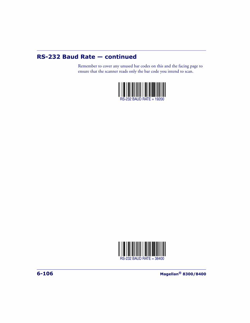
6-106 Magellan® 8300/8400
RS-232 Baud Rate — continuedRemember to cover any unused bar codes on this and the facing page to ensure that the scanner reads only the bar code you intend to scan.
RS-232 BAUD RATE = 19200
RS-232 BAUD RATE = 38400
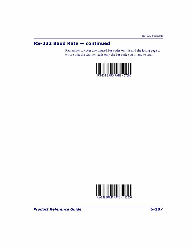
RS-232 Features
Product Reference Guide 6-107
RS-232 Baud Rate — continuedRemember to cover any unused bar codes on this and the facing page to ensure that the scanner reads only the bar code you intend to scan.
RS-232 BAUD RATE = 57600
RS-232 BAUD RATE = 115200
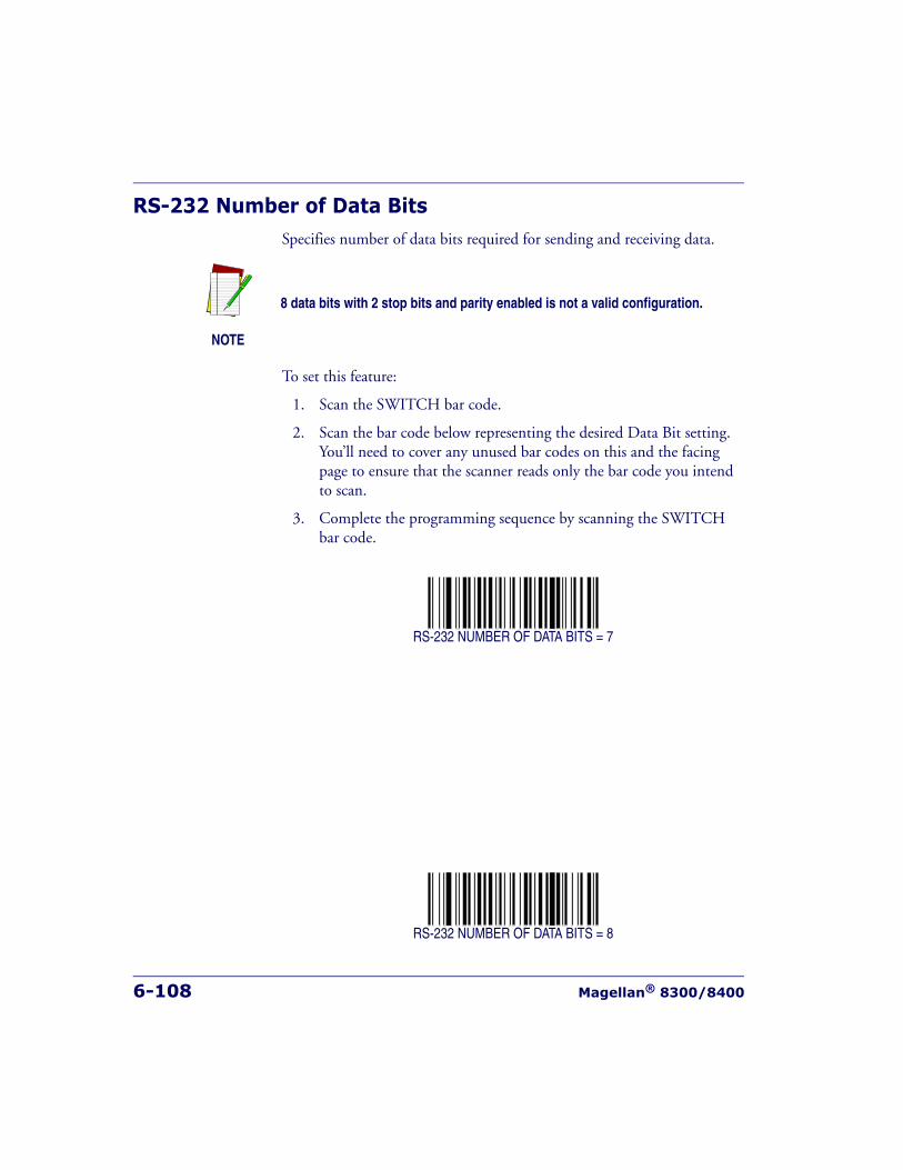
6-108 Magellan® 8300/8400
RS-232 Number of Data BitsSpecifies number of data bits required for sending and receiving data.
To set this feature:
1. Scan the SWITCH bar code.
2. Scan the bar code below representing the desired Data Bit setting. You’ll need to cover any unused bar codes on this and the facing page to ensure that the scanner reads only the bar code you intend to scan.
3. Complete the programming sequence by scanning the SWITCH bar code.
RS-232 NUMBER OF DATA BITS = 7
RS-232 NUMBER OF DATA BITS = 8
NOTE
8 data bits with 2 stop bits and parity enabled is not a valid configuration.
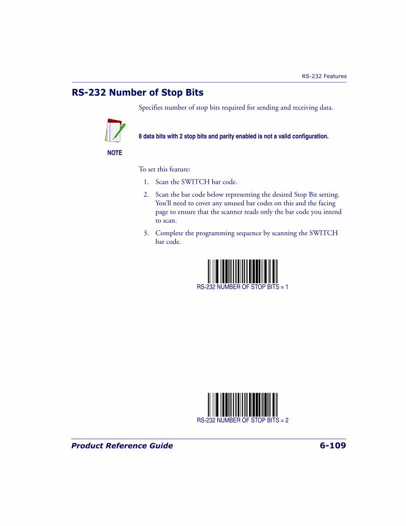
RS-232 Features
Product Reference Guide 6-109
RS-232 Number of Stop BitsSpecifies number of stop bits required for sending and receiving data.
To set this feature:
1. Scan the SWITCH bar code.
2. Scan the bar code below representing the desired Stop Bit setting. You’ll need to cover any unused bar codes on this and the facing page to ensure that the scanner reads only the bar code you intend to scan.
3. Complete the programming sequence by scanning the SWITCH bar code.
RS-232 NUMBER OF STOP BITS = 1
RS-232 NUMBER OF STOP BITS = 2
NOTE
8 data bits with 2 stop bits and parity enabled is not a valid configuration.
6-110 Magellan® 8300/8400
RS-232 ParitySpecifies parity required for sending and receiving data.
Options for this setting are:
• RS-232 PARITY = NONE
• RS-232 PARITY = EVEN
• RS-232 PARITY = ODD
To set this feature:
1. Scan the SWITCH bar code.
2. Scan the bar code below or on the following pages representing the desired Parity setting. You’ll need to cover any unused bar codes, as well as facing pages to ensure that the scanner reads only the bar code you intend to scan.
3. Complete the programming sequence by scanning the SWITCH bar code.
RS-232 PARITY = NONE
NOTE
8 data bits with 2 stop bits and parity enabled is not a valid configuration.

RS-232 Features
Product Reference Guide 6-111
RS-232 Parity — continuedRemember to cover any unused bar codes on this and the facing page to ensure that the scanner reads only the bar code you intend to scan.
RS-232 PARITY = EVEN
RS-232 PARITY = ODD
6-112 Magellan® 8300/8400
RS-232 Hardware ControlEnables/disables use of the RS-232 CTS signal for flow control and/or scan control.
Options are:
• Disable — The scanner transmits to the host regardless of any activ-ity on the CTS line.
• Enable CTS Flow Control — The CTS signal controls transmission of data to the host.
• Enable CTS Scan Control — The CTS line must be active for scan-ner to read and transmit data. While the CTS line is inactive, scan-ner remains in a host- disabled state; following a successful label transmission, the CTS signal must transition to inactive and then to active to enable scanning for the next label.
• Enable Magellan SL CTS scan control — Emulates default Magel-lan SL setting for this feature.
To set this feature:
1. Scan the SWITCH bar code.
2. Scan bar code below or from the following page for the desired set-ting. You’ll need to cover any unused bar codes on facing pages to ensure that the scanner reads only the bar code you intend to scan.
3. Complete the programming sequence by scanning the SWITCH bar code.
RS-232 HARDWARE CONTROL = DISABLE
RS-232 Features
Product Reference Guide 6-113
RS-232 Hardware Control — continuedRemember to cover any unused bar codes on this and the facing page to ensure that the scanner reads only the bar code you intend to scan.
RS-232 HARDWARE CONTROL = ENABLE CTS FLOW CONTROL
RS-232 HARDWARE CONTROL = ENABLE CTS SCAN CONTROL
6-114 Magellan® 8300/8400
RS-232 Hardware Control — continuedRemember to cover any unused bar codes on this and the facing page to ensure that the scanner reads only the bar code you intend to scan.
RS-232 HARDWARE CONTROL = ENABLE MGL SL CTS SCAN CONTROL

RS-232 Features
Product Reference Guide 6-115
RS-232 Intercharacter DelaySpecifies delay between the end of one character and the beginning of the next in 10-millisecond increments.
To set the RS-232 Intercharacter Delay:
1. Scan the SWITCH bar code.
2. Scan the bar code below, SET RS-232 INTERCHARACTER DELAY. You’ll need to cover any unused bar codes on this and the facing page to ensure that the scanner reads only the bar code you intend to scan.
3. Scan the appropriate digits from the keypad in Appendix C that rep-resent the desired delay. The selectable range is 0-100, which is the delay in 10-millisecond increments. Pad all single and double digit numbers with leading zeroes to yield a three-digit entry (000-100).Examples:
001 = 10ms
005 = 50ms
040 = 400ms
100 = 1,000ms (1 second)
4. The scanner will automatically exit Programming Mode when the appropriate amount of digits have been scanned.
SET RS-232 INTERCHARACTER DELAY
6-116 Magellan® 8300/8400
RS-232 Software Flow ControlEnables/disables RS-232 Flow Control using XON/ XOFF characters. .
To set this feature:
1. Scan the SWITCH bar code.
2. Scan either the enable or disable bar code below. You’ll need to cover any unused bar codes on this and the facing page to ensure that the scanner reads only the bar code you intend to scan.
3. Complete the programming sequence by scanning the SWITCH bar code.
RS-232 SOFTWARE FLOW CONTROL = DISABLE
RS-232 SOFTWARE FLOW CONTROL = ENABLE
NOTE
This item will be ignored when the feature, RS-232 NAK Character, isenabled
RS-232 Features
Product Reference Guide 6-117
RS-232 Host EchoWhen enabled, this feature passes all data through the scanner to the host as it comes in. This feature is used for applications where “daisy chaining” of RS-232 devices onto the same cable is necessary. If, for example, one of the devices in the chain is a terminal where someone is entering data while another person is simultaneously scanning a bar code requiring transmis-sion to the host, the scanner will wait for the RS-232 channel to be quiet for a specified period of time (set via RS-232 Host Echo Quiet Interval).The scanner can be set to observe this delay before sending its data in order to avoid RS-232 transmission conflicts.
To enable/disable this feature:
1. Scan the SWITCH bar code.
2. Scan either the enable or disable bar code below. You’ll need to cover any unused bar codes on this and the facing page to ensure that the scanner reads only the bar code you intend to scan.
3. Complete the programming sequence by scanning the SWITCH bar code.
RS-232 HOST ECHO = DISABLE
RS-232 HOST ECHO = ENABLE
NOTE
When RS-232 Host Echo is enabled, the following features are ignored: RS-232 Software Flow Control and RS-232 ACK NAK Enable as well as allother ACK/ NAK related operations, plus processing of RS-232 host com-mands.
6-118 Magellan® 8300/8400
RS-232 Host Echo Quiet IntervalThis setting specifies the time interval of RS-232 channel inactivity which must transpire before the scanner will break the host echo loop to transmit the bar code data that has just been scanned to the host.
• 0 - 100 = Time in 10-millisecond increments.
To set the Host Echo Quiet Interval:
1. Scan the SWITCH bar code.
2. Scan the bar code below, SET RS-232 HOST ECHO QUIET INTERVAL. You’ll need to cover any unused bar codes on this and the facing page to ensure that the scanner reads only the bar code you intend to scan.
3. Scan the appropriate digits from the keypad in Appendix C that rep-resent the desired timeout. The selectable range is 0-100, which is the timeout in 10-millisecond increments. Pad all single and double digit numbers with leading zeroes to yield a three-digit entry (000-100).Examples:
001 = 10ms
005 = 50ms
040 = 400ms
100 = 1,000ms (1 second)
4. The scanner will automatically exit Programming Mode when the appropriate amount of digits have been scanned.
SET RS-232 HOST ECHO QUIET INTERVAL
RS-232 Features
Product Reference Guide 6-119
RS-232 Ignore Host CommandsWhen set to ignore host commands, the scanner will ignore all host com-mands except for the minimum set necessary to keep the interface active, transmit labels, and transmit scale information. For normal operation of the interface, disable this feature.
To set this feature:
1. Scan the SWITCH bar code.
2. Scan your selection from the bar codes below. You’ll need to cover any unused bar codes on this and the facing page to ensure that the scanner reads only the bar code you intend to scan.
3. Complete the programming sequence by scanning the SWITCH bar code.
RS-232 IGNORE HOST COMMANDS =NORMAL (DO NOT IGNORE HOST COMMANDS)
RS-232 IGNORE HOST COMMANDS = ENABLE
6-120 Magellan® 8300/8400
RS-232 TTLSpecifies whether RS-232 interface provides TTL levels on the output pins TxD and RTS.
Choices are:
• Normal RS-232 levels
• TTL levels
To set this feature:
1. Scan the SWITCH bar code.
2. Scan the bar code below which represents the desired setting for this feature. You’ll need to cover any unused bar codes on this and the facing page to ensure that the scanner reads only the bar code you intend to scan.
3. Complete the programming sequence by scanning the SWITCH bar code.
RS-232 LEVELS = NORMAL RS-232
RS-232 LEVELS = TTL
RS-232 Features
Product Reference Guide 6-121
RS-232 TTL InvertEnables/disables inversion of TTL.
To set this feature:
1. Scan the SWITCH bar code.
2. Scan the bar code below which represents the desired setting for this feature. You’ll need to cover any unused bar codes on this and the facing page to ensure that the scanner reads only the bar code you intend to scan.
3. Complete the programming sequence by scanning the SWITCH bar code.
RS-232 TTL INVERT = NO INVERT
RS-232 TTL INVERT = INVERT
6-122 Magellan® 8300/8400
RS-232 ICL DC1 Character Delay EnableEnables/disables the ability of the scanner to delay a DC1 response for 40 milliseconds.
To set this feature:
1. Scan the SWITCH bar code.
2. Scan the bar code below which represents the desired setting for this feature. You’ll need to cover any unused bar codes on this and the facing page to ensure that the scanner reads only the bar code you intend to scan.
3. Complete the programming sequence by scanning the SWITCH bar code.
RS-232 ICL DC1 CHARACTER DELAY = DISABLE
RS-232 ICL DC1 CHARACTER DELAY = ENABLE
RS-232 Features
Product Reference Guide 6-123
RS-232 Team POS ICL ScaleEnables/disables the ability of the scanner to enter TEAM POS ICL Scale mode.
To set this feature:
1. Scan the SWITCH bar code.
2. Scan the bar code below which represents the desired setting for this feature. You’ll need to cover any unused bar codes on this and the facing page to ensure that the scanner reads only the bar code you intend to scan.
3. Complete the programming sequence by scanning the SWITCH bar code.
RS-232 TEAM POS ICL SCALE MODE = DISABLE
RS-232 TEAM POS ICL SCALE MODE = ENABLE
6-124 Magellan® 8300/8400
RS-232 Beep on ASCII BELEnables/disables ability of scanner to beep (sound a good read tone) on receiving an ASCII BEL (07 hex).
• Disable
• Enable
To enable/disable this feature:
1. Scan the SWITCH bar code.
2. Scan either the enable or disable bar code below. You’ll need to cover any unused bar codes on this and the facing page to ensure that the scanner reads only the bar code you intend to scan.
3. Complete the programming sequence by scanning the SWITCH bar code.
RS-232 BEEP ON ASCII BEL = DISABLE
RS-232 BEEP ON ASCII BEL = ENABLE
RS-232 Features
Product Reference Guide 6-125
RS-232 Beep After WeighEnables/disables the ability of the scanner to beep after weight data is transmitted to the host. Scale interfaces that support this item are: RS-232 ICL, RS-232 SASI, and RS-232 Single Cable.
To enable/disable the Beep After Weigh feature:
1. Scan the SWITCH bar code.
2. Scan either the enable or disable bar code below. You’ll need to cover any unused bar codes on this and the facing page to ensure that the scanner reads only the bar code you intend to scan.
3. Complete the programming sequence by scanning the SWITCH bar code.
BEEP AFTER WEIGH = DISABLE
BEEP AFTER WEIGH = ENABLE
6-126 Magellan® 8300/8400
RS-232 Beep on Not on FileSelect for the host to beep (or not) when a not-on-file condition is detected by the host. This feature is also applicable to single cable RS-232.
RS-232 BEEP ON NOT ON FILE = DISABLE
RS-232 BEEP ON NOT ON FILE = ENABLE
RS-232 Features
Product Reference Guide 6-127
RS-232 ACK NAK EnableThis enables/disables the ability of the scanner to support the RS-232 ACK/NAK protocol. When configured, the scanner and/or host sends an “ACK” when it receives data properly, and sends “NAK” when the data is in error. Selections for this option are:
• Disable
• Label Transmission — the scanner expects an ACK/NAK response from the host when a label is sent)
• Host Acknowledgement — Enabled for Host Commands (the scan-ner will respond with ACK/NAK when the host sends a command)
• Label & Host — Enabled for both Label Transmission & Host Commands
To select the option for RS-232 ACK NAK Enable:
1. Scan the SWITCH bar code.
2. Scan the desired option from bar codes below and on the following page. You’ll need to cover any unused bar codes on this and the fac-ing page to ensure that the scanner reads only the bar code you intend to scan.
3. Complete the programming sequence by scanning the SWITCH bar code.
RS-232 ACK NAK = DISABLE
RS-232 ACK/NAK = LABEL TRANSMISSION
6-128 Magellan® 8300/8400
RS-232 ACK NAK Enable — continuedRemember to cover any unused bar codes on this and the facing page to ensure that the scanner reads only the bar code you intend to scan.
RS-232 ACK/NAK = HOST ACKNOWLEDGEMENT
RS-232 ACK/NAK = LABEL & HOST
RS-232 Features
Product Reference Guide 6-129
RS-232 ACK CharacterThis feature specifies which ASCII character will be used as an ACK char-acter.
To specify the RS-232 ACK Character:
1. Scan the SWITCH bar code.
2. Scan the bar code, SET RS-232 ACK CHARACTER below. You’ll need to cover any unused bar codes on this and the facing page to ensure the scanner reads only the bar code you intend to scan.
3. Scan the appropriate digits from the keypad in Appendix C that rep-resent the hex designation for the desired character. A table contain-ing the ASCII Character Set and their corresponding Hex Values is available in the inside back cover of this manual. ASCII parameters must be input by scanning a pair of hexadecimal digits for the desired character. For example, if ASCII “A” were the desired ACK character, you would scan the digits “4”, then “1” (the ASCII corre-sponding hex value).
4. The scanner will automatically exit Programming Mode when the appropriate amount of digits/characters have been scanned.
SET RS-232 ACK CHARACTER
NOTE
DO NOT set this feature to use previously defined characters such as XON,XOFF or host commands as this will conflict with normal operation of thesecharacters. 8-bit data is not recognized when the feature, RS-232 Numberof Data Bits, is set to 7 data bits.
6-130 Magellan® 8300/8400
RS-232 NAK CharacterThis feature specifies which ASCII character will be used as a NAK char-acter.
To specify the RS-232 NAK Character:
1. Scan the SWITCH bar code.
2. Scan the bar code, SET RS-232 NAK CHARACTER below. You’ll need to cover any unused bar codes on this and the facing page to ensure the scanner reads only the bar code you intend to scan.
3. Scan the appropriate digits from the keypad in Appendix C that rep-resent the hex designation for the desired character. A table contain-ing the ASCII Character Set and their corresponding Hex Values is available in the inside back cover of this manual. ASCII parameters must be input by scanning a pair of hexadecimal digits for the desired character. For example, if ASCII “A” were the desired NAK character, you would scan the digits “4”, then “1” (the ASCII corre-sponding hex value).
4. The scanner will automatically exit Programming Mode when the appropriate amount of digits/characters have been scanned.
SET RS-232 NAK CHARACTER
NOTE
DO NOT set this feature to use previously defined characters such as XON,XOFF or host commands as this will conflict with normal operation of thesecharacters. 8-bit data is not recognized when the feature, RS-232 Numberof Data Bits, is set to 7 data bits.
RS-232 Features
Product Reference Guide 6-131
RS-232 Retry on ACK NAK TimeoutThis option specifies the action scanner performs on expiration of the RS-232 ACK NAK Timeout Value.
To set this feature:
1. Scan the SWITCH bar code.
2. Scan either the enable or disable bar code below. You’ll need to cover any unused bar codes on this and the facing page to ensure that the scanner reads only the bar code you intend to scan.
3. Complete the programming sequence by scanning the SWITCH bar code.
RS-232 RETRY ON ACK NAK TIMEOUT = DISABLE
RS-232 RETRY ON ACK NAK TIMEOUT = ENABLE
6-132 Magellan® 8300/8400
RS-232 ACK NAK Timeout ValueThis item specifies the time the scanner will wait for an ACK character from the host following a label transmission.
• 0 = Infinite timeout
• 1 - 75 = Timeout in 200-millisecond increments
To set the ACK NAK Timeout Value:
1. Scan the SWITCH bar code.
2. Scan the bar code below, SET RS-232 ACK NAK TIMEOUT VALUE. You’ll need to cover any unused bar codes on this and the facing page to ensure that the scanner reads only the bar code you intend to scan.
3. Scan the appropriate digits from the keypad in Appendix C that rep-resent the desired timeout. A setting of 0 specifies an infinite time-out. The remaining selectable range is 1-75, which is the timeout in 200-millisecond increments. Pad all single digit numbers with lead-ing zeroes to yield a three-digit entry (000-075).Examples:
000 = Infinite timeout
001 = 200ms
005 = 1,000ms (1 second)
040 = 8,000ms (8 seconds)
075 = 15,000ms (15 seconds)
4. The scanner will automatically exit Programming Mode when the appropriate amount of digits have been scanned.
SET RS-232 ACK NAK TIMEOUT VALUE
RS-232 Features
Product Reference Guide 6-133
RS-232 ACK NAK Retry CountThis feature sets the number of times for the scanner to retry a label trans-mission under a retry condition.
To set the RS-232 ACK NAK Retry Count:
1. Scan the SWITCH bar code.
2. Scan the bar code, SET RS-232 ACK NAK RETRY COUNT below. You’ll need to cover any unused bar codes on this and the facing page to ensure that the scanner reads only the bar code you intend to scan.
3. Scan the appropriate digits from the keypad in Appendix C that rep-resent the desired number. The selectable range is 0-255 resets. Pad all single and double digit numbers with leading zeroes to yield a three-digit entry (000-255).
4. The scanner will automatically exit Programming Mode when the appropriate amount of digits have been scanned.
SET RS-232 ACK NAK RETRY COUNT
NOTE
A setting of 255 specifies “retry forever.”

6-134 Magellan® 8300/8400
RS-232 ACK NAK Error HandlingThis item specifies the method the scanner will use to handle errors detected while waiting to receive the ACK character from the host. Errors include unrecognized host commands and communication errors such as parity or framing errors.
• Ignore Errors (recommended setting)
• Assume ACK (risk of lost label data)
• Assume NAK (risk of duplicate label)
To select the option for RS-232 ACK NAK Error Handling:
1. Scan the SWITCH bar code.
2. Scan the desired option from the bar codes below. You’ll need to cover any unused bar codes on this and the facing page to ensure that the scanner reads only the bar code you intend to scan.
3. Complete the programming sequence by scanning the SWITCH bar code.
RS-232 ACK NAK ERROR HANDLING = IGNORE ERRORS
RS-232 Features
Product Reference Guide 6-135
RS-232 ACK NAK Error Handling — continuedRemember to cover any unused bar codes on this and the facing page to ensure that the scanner reads only the bar code you intend to scan.
RS-232 ACK NAK ERROR HANDLING = ASSUME ACK
RS-232 ACK NAK ERROR HANDLING = ASSUME NAK
6-136 Magellan® 8300/8400
RS-232 Indicate Transmission FailureEnables/disables an audible error indication upon a transmission failure.
RS-232 INDICATE TRANSMISSION FAILURE = DISABLE
RS-232 INDICATE TRANSMISSION FAILURE = ENABLE
Single Cable RS-232 Options
Product Reference Guide 6-137
Single Cable RS-232 OptionsThe RS-232 Single Cable interface shares some configuration options with other RS-232 interfaces. Rather than repeat them in this chapter as Single Cable options, please find them referenced as follows:
• RS-232 Baud Rate on page 104
• RS-232 Number of Data Bits on page 108
• RS-232 Number of Stop Bits on page 109
• RS-232 Parity on page 110
• RS-232 Software Flow Control on page 116
• RS-232 Beep After Weigh on page 125
• RS-232 Beep on Not on File on page 126
6-138 Magellan® 8300/8400
Single Cable RS-232 Scanner Only ProtocolThis sets the type of interface protocol that will be used in Single Cable RS-232.
Options are:
• Scanner/scale RS-232 protocol
• Scanner only RS-232 protocol
To set this feature:
1. Scan the SWITCH bar code.
2. Scan the bar code below representing the desired option. You’ll need to cover any unused bar codes on this and the facing page to ensure that the scanner reads only the bar code you intend to scan.
3. Complete the programming sequence by scanning the SWITCH bar code.
SINGLE CABLE RS-232 PROTOCOL = SCANNER/SCALE
SINGLE CABLE RS-232 PROTOCOL = SCANNER ONLY

Single Cable RS-232 Options
Product Reference Guide 6-139
Single Cable RS-232 Stale Weight TimeoutSpecifies the amount of time (in 10 msec increments) that scale data is presented to the host before being discarded.
To set the Timeout:
1. Scan the SWITCH bar code.
2. Scan your selection from the bar codes below. You’ll need to cover any unused bar codes on this and the facing page to ensure that the scanner reads only the bar code you intend to scan.
3. Complete the programming sequence by scanning the SWITCH bar code.
STALE WEIGHT TIMEOUT = 200 msec
STALE WEIGHT TIMEOUT = 230 msec

6-140 Magellan® 8300/8400
Single Cable RS-232 Stale Weight Timeout — contin-ued
Remember to cover any unused bar codes on this and the facing page to ensure that the scanner reads only the bar code you intend to scan.
STALE WEIGHT TIMEOUT = 250 msec
STALE WEIGHT TIMEOUT = 330 msec
Single Cable RS-232 Options
Product Reference Guide 6-141
Single Cable RS-232 Scale — Transmit Weight DigitsSpecifies whether the scale transmits weight data as five digits or as four digits.
To set this feature:
1. Scan the SWITCH bar code.
2. Scan the bar code below representing the desired option. You’ll need to cover any unused bar codes on this and the facing page to ensure that the scanner reads only the bar code you intend to scan.
3. Complete the programming sequence by scanning the SWITCH bar code.
TRANSMIT WEIGHT DIGITS = FIVE DIGITS
TRANSMIT WEIGHT DIGITS = FOUR DIGITS
6-142 Magellan® 8300/8400
Single Cable Manufacturer ExtensionsEnables/Disables manufacturer1 extensions to the Single Cable RS-232 interface. These extensions communicate scale calibration information to the host.
To set this feature:
1. Scan the SWITCH bar code.
2. Scan either the enable or disable bar code below. You’ll need to cover any unused bar codes on this and the facing page to ensure that the scanner reads only the bar code you intend to scan.
3. Complete the programming sequence by scanning the SWITCH bar code.
SINGLE CABLE MANUFACTURER EXTENSIONS = DISABLE
SINGLE CABLE MANUFACTURER EXTENSIONS = ENABLE
1. The manufacturer of the scanner.
Single Cable RS-232 Options
Product Reference Guide 6-143
Single Cable Pacesetter Plus EnableEnables/disables the scanner’s ability to send Pacesetter Plus information as trailers to UPC/EAN label data.
To set this feature:
1. Scan the SWITCH bar code.
2. Scan either the enable or disable bar code below. You’ll need to cover any unused bar codes on this and the facing page to ensure that the scanner reads only the bar code you intend to scan.
3. Complete the programming sequence by scanning the SWITCH bar code.
SINGLE CABLE PACESETTER PLUS = DISABLE
SINGLE CABLE PACESETTER PLUS = ENABLE
6-144 Magellan® 8300/8400
Single Cable RS-232 RTS CTS SelectionSpecifies how RTS and CTS are used to control the data flow. RTS is con-trolled by the Scanner and can be continuously held high/low, or can be asserted during label transmission. The scanner looks at CTS, as the con-figuration values state, to determine when to send label data.
Choices are:
• Option 0 = RTS is held in low state and CTS is ignored
• Option 1 = RTS is held in high state and CTS is ignored
• Option 2 = Assert RTS and wait for CTS to be asserted
• Option 3 = Assert RTS and ignore CTS
• Option 4 = RTS held low, wait for CTS to be asserted
• Option 5 = RTS held high, wait for CTS to be asserted
To set this feature:
1. Scan the SWITCH bar code.
2. Scan a bar code below or on the following pages representing the desired option. You’ll need to cover any unused bar codes, as well as facing pages to ensure that the scanner reads only the bar code you intend to scan.
3. Complete the programming sequence by scanning the SWITCH bar code.
RTS CTS SELECTION = OPTION 0
RTS CTS SELECTION = OPTION 1
Single Cable RS-232 Options
Product Reference Guide 6-145
Single Cable RS-232 RTS CTS Selection — continuedRemember to cover any unused bar codes on this and the facing page to ensure that the scanner reads only the bar code you intend to scan.
RTS CTS SELECTION = OPTION 2
RTS CTS SELECTION = OPTION 3
6-146 Magellan® 8300/8400
Single Cable RS-232 RTS CTS Selection — continuedRemember to cover any unused bar codes on this and the facing page to ensure that the scanner reads only the bar code you intend to scan.
RTS CTS SELECTION = OPTION 4
RTS CTS SELECTION = OPTION 5
Single Cable RS-232 Options
Product Reference Guide 6-147
Single Cable RS-232 Use BCCEnables/disables the ability of the scanner to use BCC.
To set this feature:
1. Scan the SWITCH bar code.
2. Scan either the enable or disable bar code below. You’ll need to cover any unused bar codes on this and the facing page to ensure that the scanner reads only the bar code you intend to scan.
3. Complete the programming sequence by scanning the SWITCH bar code.
SINGLE CABLE RS-232 USE BCC = DISABLE
SINGLE CABLE RS-232 USE BCC = ENABLE

6-148 Magellan® 8300/8400
Single Cable RS-232 Use ACK/NAKEnables/disables the ability of the scanner to use ACK/NAK.
To set this feature:
1. Scan the SWITCH bar code.
2. Scan either the enable or disable bar code below. You’ll need to cover any unused bar codes on this and the facing page to ensure that the scanner reads only the bar code you intend to scan.
3. Complete the programming sequence by scanning the SWITCH bar code.
SINGLE CABLE RS-232 USE ACK/NAK = DISABLE
SINGLE CABLE RS-232 USE ACK/NAK = ENABLE
Single Cable RS-232 Options
Product Reference Guide 6-149
Single Cable RS-232 Use STXEnables/disables the ability of the scanner to use STX.
To set this feature:
1. Scan the SWITCH bar code.
2. Scan either the enable or disable bar code below. You’ll need to cover any unused bar codes on this and the facing page to ensure that the scanner reads only the bar code you intend to scan.
3. Complete the programming sequence by scanning the SWITCH bar code.
SINGLE CABLE RS-232 USE STX = DISABLE
SINGLE CABLE RS-232 USE STX = ENABLE
6-150 Magellan® 8300/8400
Set Single Cable RS-232 STX CharacterThis feature selects the STX character.
To specify the STX Character:
1. Scan the SWITCH bar code.
2. Scan the bar code, SET SINGLE CABLE RS-232 STX CHARAC-TER below. You’ll need to cover any unused bar codes on this and the facing page to ensure the scanner reads only the bar code you intend to scan.
3. Scan the appropriate characters/digits from the keypad in AppendixC that represent the decimal designation for the desired character. A table containing the ASCII Character Set and their corresponding decimal values is available in the inside back cover of this manual. ASCII parameters must be input by scanning decimal digits for each character. Pad all numbers with leading zeroes to yield a three-digit entry (001-127). Thus, to set a single character value of A, bar codes containing the digits ‘0’, ‘6’ and ‘5’ must be scanned. The selectable range for this option is any decimal value from 001 to 127.
4. The scanner will automatically exit Programming Mode when the appropriate amount of digits have been scanned.
SET SINGLE CABLE RS-232 STX CHARACTER
Single Cable RS-232 Options
Product Reference Guide 6-151
Set Single Cable RS-232 ETX CharacterAllows selection of the ETX character.
To specify the ETX Character:
1. Scan the SWITCH bar code.
2. Scan the bar code, SET SINGLE CABLE RS-232 ETX CHARAC-TER below. You’ll need to cover any unused bar codes on this and the facing page to ensure the scanner reads only the bar code you intend to scan.
3. Scan the appropriate characters/digits from the keypad in AppendixC that represent the decimal designation for the desired character. A table containing the ASCII Character Set and their corresponding decimal values is available in the inside back cover of this manual. ASCII parameters must be input by scanning decimal digits for each character. Pad all numbers with leading zeroes to yield a three-digit entry (001-127). Thus, to set a single character value of A, bar codes containing the digits ‘0’, ‘6’ and ‘5’ must be scanned. The selectable range for this option is any decimal value from 001 to 127.
4. The scanner will automatically exit Programming Mode when the appropriate amount of digits have been scanned.
SET SINGLE CABLE RS-232 ETX CHARACTER
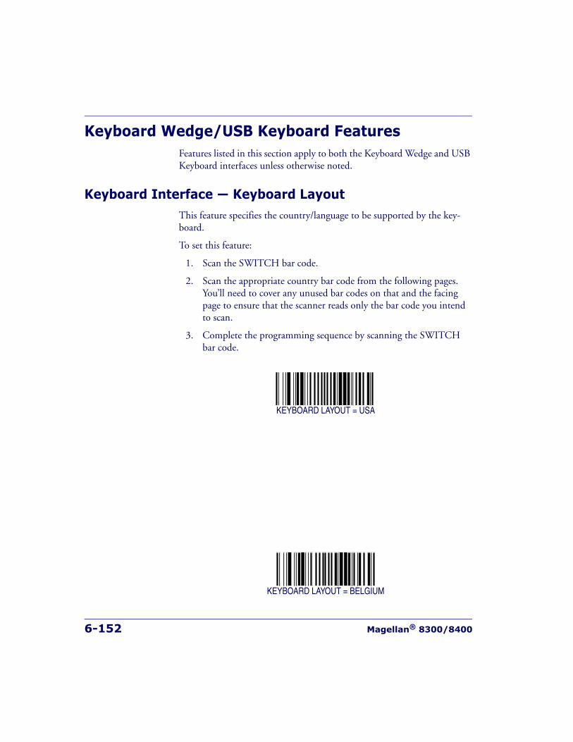
6-152 Magellan® 8300/8400
Keyboard Wedge/USB Keyboard FeaturesFeatures listed in this section apply to both the Keyboard Wedge and USB Keyboard interfaces unless otherwise noted.
Keyboard Interface — Keyboard LayoutThis feature specifies the country/language to be supported by the key-board.
To set this feature:
1. Scan the SWITCH bar code.
2. Scan the appropriate country bar code from the following pages. You’ll need to cover any unused bar codes on that and the facing page to ensure that the scanner reads only the bar code you intend to scan.
3. Complete the programming sequence by scanning the SWITCH bar code.
KEYBOARD LAYOUT = USA
KEYBOARD LAYOUT = BELGIUM

Keyboard Wedge/USB Keyboard Features
Product Reference Guide 6-153
Keyboard Interface — Keyboard Layout — continuedRemember to cover any unused bar codes on this and the facing page to ensure that the scanner reads only the bar code you intend to scan.
KEYBOARD LAYOUT = BRITAIN
KEYBOARD LAYOUT = DENMARK
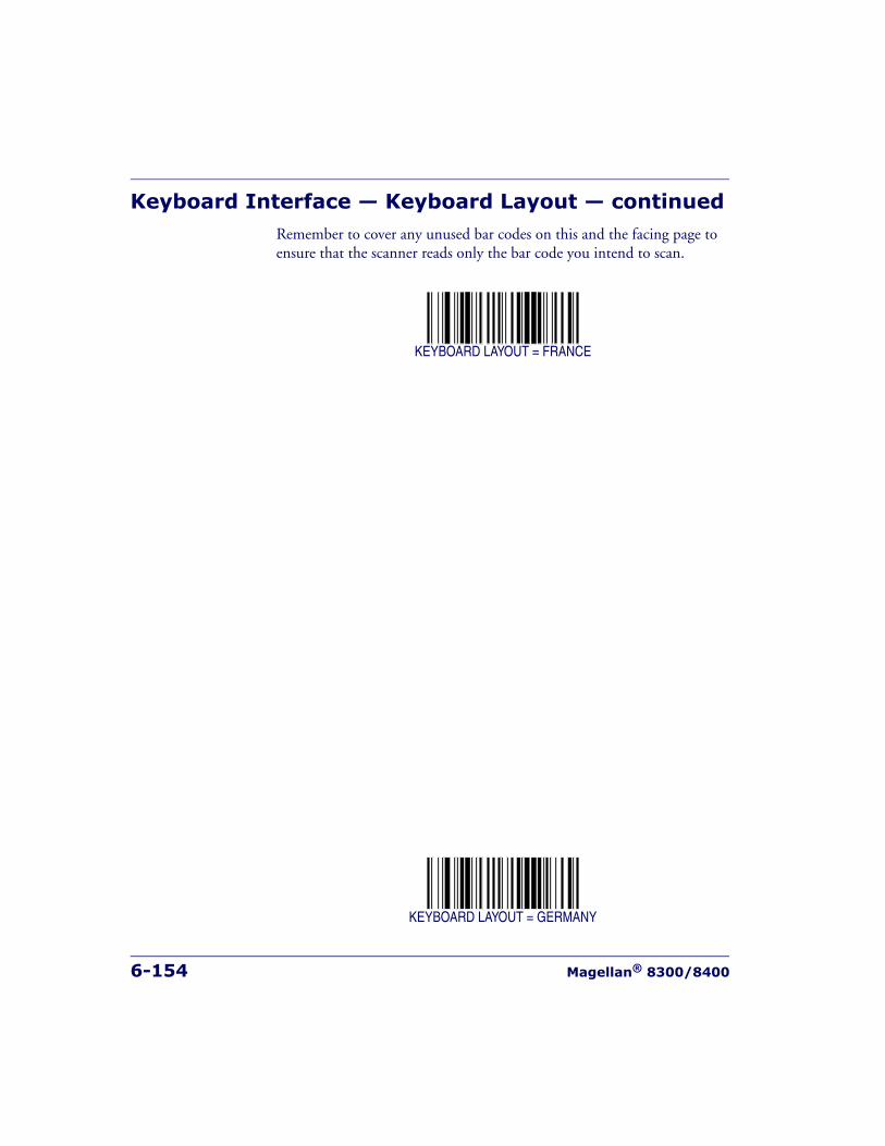
6-154 Magellan® 8300/8400
Keyboard Interface — Keyboard Layout — continuedRemember to cover any unused bar codes on this and the facing page to ensure that the scanner reads only the bar code you intend to scan.
KEYBOARD LAYOUT = FRANCE
KEYBOARD LAYOUT = GERMANY
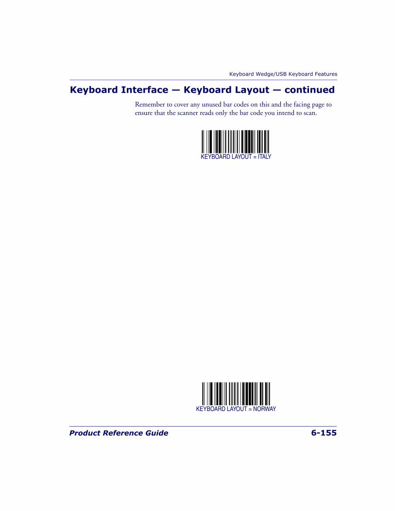
Keyboard Wedge/USB Keyboard Features
Product Reference Guide 6-155
Keyboard Interface — Keyboard Layout — continuedRemember to cover any unused bar codes on this and the facing page to ensure that the scanner reads only the bar code you intend to scan.
KEYBOARD LAYOUT = ITALY
KEYBOARD LAYOUT = NORWAY
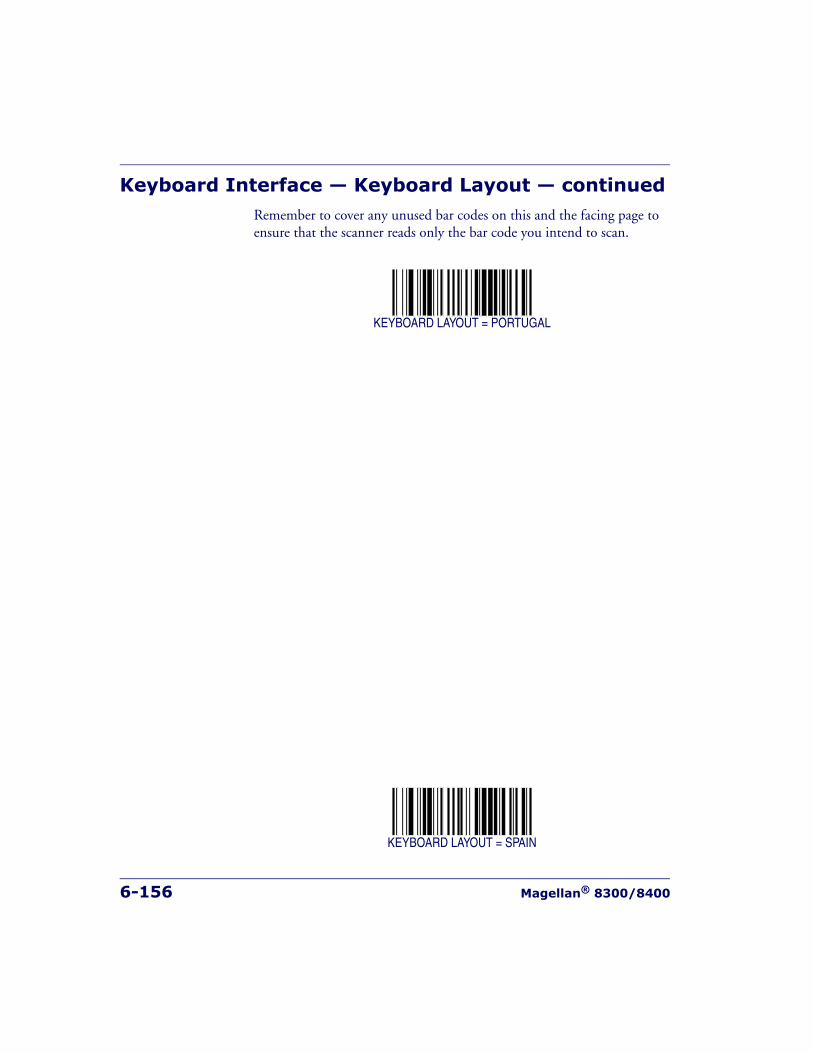
6-156 Magellan® 8300/8400
Keyboard Interface — Keyboard Layout — continuedRemember to cover any unused bar codes on this and the facing page to ensure that the scanner reads only the bar code you intend to scan.
KEYBOARD LAYOUT = PORTUGAL
KEYBOARD LAYOUT = SPAIN
Keyboard Wedge/USB Keyboard Features
Product Reference Guide 6-157
Keyboard Interface — Keyboard Layout — continuedRemember to cover any unused bar codes on this and the facing page to ensure that the scanner reads only the bar code you intend to scan.
KEYBOARD LAYOUT = SWEDEN
KEYBOARD LAYOUT = SWITZERLAND
6-158 Magellan® 8300/8400
Keyboard Interface — Keyboard Layout — continuedRemember to cover any unused bar codes on this and the facing page to ensure that the scanner reads only the bar code you intend to scan.
KEYBOARD LAYOUT = JAPANESE 106 KEY
KEYBOARD LAYOUT = HUNGARY
Keyboard Wedge/USB Keyboard Features
Product Reference Guide 6-159
Keyboard Interface — Keyboard Layout — continuedRemember to cover any unused bar codes on this and the facing page to ensure that the scanner reads only the bar code you intend to scan.
KEYBOARD LAYOUT = CZECH
KEYBOARD LAYOUT = SLOVAKIA

6-160 Magellan® 8300/8400
Keyboard Interface — Keyboard Layout — continuedRemember to cover any unused bar codes on this and the facing page to ensure that the scanner reads only the bar code you intend to scan.
KEYBOARD LAYOUT = ROMANIA
KEYBOARD LAYOUT = CROATIA
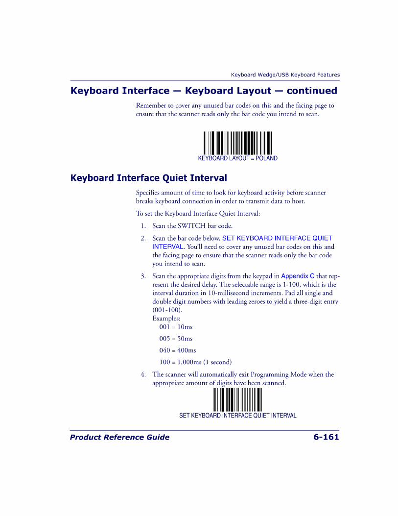
Keyboard Wedge/USB Keyboard Features
Product Reference Guide 6-161
Keyboard Interface — Keyboard Layout — continuedRemember to cover any unused bar codes on this and the facing page to ensure that the scanner reads only the bar code you intend to scan.
KEYBOARD LAYOUT = POLAND
Keyboard Interface Quiet IntervalSpecifies amount of time to look for keyboard activity before scanner breaks keyboard connection in order to transmit data to host.
To set the Keyboard Interface Quiet Interval:
1. Scan the SWITCH bar code.
2. Scan the bar code below, SET KEYBOARD INTERFACE QUIET INTERVAL. You’ll need to cover any unused bar codes on this and the facing page to ensure that the scanner reads only the bar code you intend to scan.
3. Scan the appropriate digits from the keypad in Appendix C that rep-resent the desired delay. The selectable range is 1-100, which is the interval duration in 10-millisecond increments. Pad all single and double digit numbers with leading zeroes to yield a three-digit entry (001-100).Examples:
001 = 10ms
005 = 50ms
040 = 400ms
100 = 1,000ms (1 second)
4. The scanner will automatically exit Programming Mode when the appropriate amount of digits have been scanned.
SET KEYBOARD INTERFACE QUIET INTERVAL
6-162 Magellan® 8300/8400
Keyboard Interface Caps Lock StateSpecifies the format in which the scanner sends character data..
Choices are:
• CAPS LOCK OFF — send character data in normal format.
• CAPS LOCK ON — send character data in reverse case.
• SHIFT LOCK ON — send character data in shifted case. This option only applies to Wedge G. For other interface this setting results in a CAPS LOCK OFF functionality.
• CAPS LOCK COMPENSATION MODE — This only applies to the USB Keyboard Interface. For other interfaces, this setting results in a CAPS LOCK OFF functionality.
To set this feature:
1. Scan the SWITCH bar code.
2. Scan either the enable or disable bar code below. You’ll need to cover any unused bar codes on this and the facing page to ensure that the scanner reads only the bar code you intend to scan.
3. Complete the programming sequence by scanning the SWITCH bar code.
CAPS LOCK STATE = OFF
CAPS LOCK STATE = CAPS LOCK ON
Keyboard Wedge/USB Keyboard Features
Product Reference Guide 6-163
Keyboard Interface Caps Lock State — continuedRemember to cover any unused bar codes on this and the facing page to ensure that the scanner reads only the bar code you intend to scan.
CAPS LOCK STATE = SHIFT LOCK ON
CAPS LOCK STATE = CAPS LOCK COMPENSATION MODE
6-164 Magellan® 8300/8400
Keyboard Interface — Keyboard SimulationEnables/disables ability of scanner to perform host communications nor-mally performed by attached keyboard.
All PCs check the keyboard status during the power-on Selftest. It is rec-ommended that you enable this function if you are working without a keyboard installation. It simulates keyboard timing and passes the key-board status to the PC during power-on.
To set this feature:
1. Scan the SWITCH bar code.
2. Scan either the enable or disable bar code below. You’ll need to cover any unused bar codes on this and the facing page to ensure that the scanner reads only the bar code you intend to scan.
3. Complete the programming sequence by scanning the SWITCH bar code.
KEYBOARD SIMULATION = DISABLE
KEYBOARD SIMULATION = ENABLE
NOTE
This feature does not apply to the USB Keyboard interface.
Keyboard Wedge/USB Keyboard Features
Product Reference Guide 6-165
Keyboard Interface — Control CharactersSpecifies how the scanner transmits ASCII control characters to the host.
Choices are:
• Disable Control Characters
• Enable transmission of control characters to host
• Send characters between 00H and 1FH according to a special func-tion-key mapping table. (This is used to send keys that are not in the normal ASCII set; a unique set is provided for each available scancode set. Reference Appendix E, Keyboard Function Key Map-pings.)
To set this feature:
1. Scan the SWITCH bar code.
2. Scan your choice from the Control Characters feature bar codes below. You’ll need to cover any unused bar codes on this and the fac-ing page to ensure that the scanner reads only the bar code you intend to scan.
3. Complete the programming sequence by scanning the SWITCH bar code.
CONTROL CHARACTERS = DISABLE
NOTE
This feature does not apply to the USB Keyboard interface.
6-166 Magellan® 8300/8400
Keyboard Interface — Control Characters — contin-ued
Remember to cover any unused bar codes on this and the facing page to ensure that the scanner reads only the bar code you intend to scan.
CONTROL CHARACTERS = ENABLE TRANSMISSION OF CTL CHARACTERS
CONTROL CHARACTERS = ENABLE FUNCTION KEY MAPPING
Keyboard Wedge/USB Keyboard Features
Product Reference Guide 6-167
Keyboard Interface — Intercharacter DelaySets the delay between the end of one character and the beginning of the next, in 10 millisecond increments.
To specify the intercharacter delay:
1. Scan the SWITCH bar code.
2. Scan the bar code below, SET KEYBOARD WEDGE INTERCHAR-ACTER DELAY. You’ll need to cover any unused bar codes on this and the facing page to ensure that the scanner reads only the bar code you intend to scan.
3. Scan the appropriate digits from the keypad in Appendix C that rep-resent the desired delay. The selectable range is 0-100, which is the delay in 10-millisecond increments. Pad all single and double digit numbers with leading zeroes to yield a three-digit entry (000-100).Examples:
001 = 10ms
005 = 50ms
040 = 400ms
100 = 1,000ms (1 second)
4. The scanner will automatically exit Programming Mode when the appropriate amount of digits have been scanned.
SET KEYBOARD WEDGE INTERCHARACTER DELAY
6-168 Magellan® 8300/8400
Symbology Programming
Coupon ControlUsed to control the method of processing coupon labels.
Options are:
• Disable coupon decoding
• Enable UPC/EAN coupon decoding
• Enable RSS coupon decoding
To set this feature:
1. Scan the SWITCH bar code.
2. Scan either the enable or disable bar code below. You’ll need to cover any unused bar codes on this and the facing page to ensure that the scanner reads only the bar code you intend to scan.
3. Complete the programming sequence by scanning the SWITCH bar code.
COUPON CONTROL = DISABLE
NOTE
If the scanner’s interface type must be changed, always be sure that inter-face configuration is the FIRST item scanned during a programming ses-sion. (Selecting an interface type resets ALL other configuration items —including symbology programming — to the factory default for that inter-face type.)
Symbology Programming
Product Reference Guide 6-169
Coupon Control — continuedRemember to cover any unused bar codes on this and the facing page to ensure that the scanner reads only the bar code you intend to scan.
COUPON CONTROL = ENABLE UPC/EAN COUPON DECODING
COUPON CONTROL = ENABLE DATABAR COUPON DECODING
6-170 Magellan® 8300/8400
UPC-A EnableEnables/disables the ability of the scanner to decode UPC-A labels.
To set this feature:
1. Scan the SWITCH bar code.
2. Scan either the enable or disable bar code below. You’ll need to cover any unused bar codes on this and the facing page to ensure that the scanner reads only the bar code you intend to scan.
3. Complete the programming sequence by scanning the SWITCH bar code.
UPC-A = DISABLE
UPC-A = ENABLE
UPC-A Enable
Product Reference Guide 6-171
UPC-A Number System Character TransmissionEnables/disables transmission of a UPC-A number system character.
To set this feature:
1. Scan the SWITCH bar code.
2. Scan either the enable or disable bar code below. You’ll need to cover any unused bar codes on this and the facing page to ensure that the scanner reads only the bar code you intend to scan.
3. Complete the programming sequence by scanning the SWITCH bar code.
UPC-A NUMBER SYSTEM CHARACTER TRANSMISSION = DISABLE
UPC-A NUMBER SYSTEM CHARACTER TRANSMISSION = ENABLE
NOTE
This feature MUST be enabled for IBM interfaces for proper function.
6-172 Magellan® 8300/8400
UPC-A Check Character TransmissionEnables/disables transmission of a UPC-A check character.
To set this feature:
1. Scan the SWITCH bar code.
2. Scan either the enable or disable bar code below. You’ll need to cover any unused bar codes on this and the facing page to ensure that the scanner reads only the bar code you intend to scan.
3. Complete the programming sequence by scanning the SWITCH bar code.
UPC-A CHECK CHARACTER TRANSMISSION = DISABLE
UPC-A CHECK CHARACTER TRANSMISSION = ENABLE

UPC-A Enable
Product Reference Guide 6-173
Expand UPC-A to EAN-13Enables/disables expansion of UPC-A labels to EAN/JAN-13.
To set this feature:
1. Scan the SWITCH bar code.
2. Scan either the enable or disable bar code below. You’ll need to cover any unused bar codes on this and the facing page to ensure that the scanner reads only the bar code you intend to scan.
3. Complete the programming sequence by scanning the SWITCH bar code.
EXPAND UPC-A TO EAN/JAN-13 = DISABLE
EXPAND UPC-A TO EAN/JAN-13 = ENABLE

6-174 Magellan® 8300/8400
UPC-A Label IDThis feature specifies a UPC-A label ID to be added to bar code data.
To set this feature:
1. Scan the SWITCH bar code.
2. Scan the bar code, SET UPC-A LABEL ID below. You’ll need to cover any unused bar codes on this and the facing page to ensure the scanner reads only the bar code you intend to scan.
3. Scan the appropriate digits from the keypad in Appendix C that rep-resent the desired Label ID characters; entered as two hex pairs. A table containing the ASCII Character Set and their corresponding Hex Values is available in the inside back cover of this manual. ASCII parameters must be input by scanning a pair of hexadecimal digits for each character. Thus, to set a two-character value of AB, bar codes containing the digits ‘4’, ‘1’, ‘4’, and ‘2’ must be scanned. The selectable range for this option is any hex value from 00 to FF.
4. Complete the programming sequence by scanning the SWITCH bar code.
SET UPC-A LABEL ID
NOTE
The programming feature, Label ID Control, designates whether the Label IDis transmitted as a prefix or suffix or if Label ID is disabled.

UPC-A Enable
Product Reference Guide 6-175
UPC-A 2-Digit Supplemental Label IDThis feature specifies a UPC-A 2-Digit Supplemental label ID to be added to bar code data.
To set this feature:
1. Scan the SWITCH bar code.
2. Scan the bar code, SET UPC-A 2-DIGIT SUPPLEMENTAL LABEL ID below. You’ll need to cover any unused bar codes on this and the facing page to ensure the scanner reads only the bar code you intend to scan.
3. Scan the appropriate digits from the keypad in Appendix C that rep-resent the desired Label ID characters; entered as two hex pairs. A table containing the ASCII Character Set and their corresponding Hex Values is available in the inside back cover of this manual. ASCII parameters must be input by scanning a pair of hexadecimal digits for each character. Thus, to set a two-character value of AB, bar codes containing the digits ‘4’, ‘1’, ‘4’, and ‘2’ must be scanned. The selectable range for this option is any hex value from 00 to FF.
4. Complete the programming sequence by scanning the SWITCH bar code.
SET UPC-A 2-DIGIT SUPPLEMENTAL LABEL ID
NOTE
The programming feature, Label ID Control, designates whether the Label ID istransmitted as a prefix or suffix or if Label ID is disabled.

6-176 Magellan® 8300/8400
UPC-A 5-Digit Supplemental Label IDThis feature specifies a UPC-A 5-Digit Supplemental label ID to be added to bar code data.
To set this feature:
1. Scan the SWITCH bar code.
2. Scan the bar code, SET UPC-A 5-DIGIT SUPPLEMENTAL LABEL ID below. You’ll need to cover any unused bar codes on this and the facing page to ensure the scanner reads only the bar code you intend to scan.
3. Scan the appropriate digits from the keypad in Appendix C that rep-resent the desired Label ID characters; entered as two hex pairs. A table containing the ASCII Character Set and their corresponding Hex Values is available in the inside back cover of this manual. ASCII parameters must be input by scanning a pair of hexadecimal digits for each character. Thus, to set a two-character value of AB, bar codes containing the digits ‘4’, ‘1’, ‘4’, and ‘2’ must be scanned. The selectable range for this option is any hex value from 00 to FF.
4. Complete the programming sequence by scanning the SWITCH bar code.
SET UPC-A 5-DIGIT SUPPLEMENTAL LABEL ID
NOTE
The programming feature, Label ID Control, designates whether the Label IDis transmitted as a prefix or suffix or if Label ID is disabled.

UPC-A Enable
Product Reference Guide 6-177
UPC-A 128 Supplemental Label IDThis feature specifies a UPC-A 128 Supplemental label ID to be added to bar code data.
To set this feature:
1. Scan the SWITCH bar code.
2. Scan the bar code, SET UPC-A 128 SUPPLEMENTAL LABEL IDbelow. You’ll need to cover any unused bar codes on this and the fac-ing page to ensure the scanner reads only the bar code you intend to scan.
3. Scan the appropriate digits from the keypad in Appendix C that rep-resent the desired Label ID characters; entered as two hex pairs. A table containing the ASCII Character Set and their corresponding Hex Values is available in the inside back cover of this manual. ASCII parameters must be input by scanning a pair of hexadecimal digits for each character. Thus, to set a two-character value of AB, bar codes containing the digits ‘4’, ‘1’, ‘4’, and ‘2’ must be scanned. The selectable range for this option is any hex value from 00 to FF.
4. Complete the programming sequence by scanning the SWITCH bar code.
SET UPC-A 128 SUPPLEMENTAL LABEL ID
NOTE
The programming feature, Label ID Control, designates whether the Label IDis transmitted as a prefix or suffix or if Label ID is disabled.
6-178 Magellan® 8300/8400
UPC-A Minimum ReadsSpecifies the minimum number of consecutive times a UPC-A label must be decoded before it is accepted as a good read.
To set this feature:
1. Scan the SWITCH bar code.
2. Scan the bar code representing the desired option below or on the following pages. You’ll need to cover any unused bar codes on facing pages to ensure that the scanner reads only the bar code you intend to scan.
Complete the programming sequence by scanning the SWITCH bar code.
UPC-A MINIMUM READS = 1
UPC-A MINIMUM READS = 2
UPC-A Enable
Product Reference Guide 6-179
UPC-A Minimum Reads — continuedRemember to cover any unused bar codes on this and the facing page to ensure that the scanner reads only the bar code you intend to scan.
UPC-A MINIMUM READS = 3
UPC-A MINIMUM READS = 4
6-180 Magellan® 8300/8400
UPC-E EnableEnables/disables the ability of the scanner to decode UPC-E labels.
To set this feature:
1. Scan the SWITCH bar code.
2. Scan either the enable or disable bar code below. You’ll need to cover any unused bar codes on this and the facing page to ensure that the scanner reads only the bar code you intend to scan.
3. Complete the programming sequence by scanning the SWITCH bar code.
UPC-E = DISABLE
UPC-E = ENABLE

UPC-E Enable
Product Reference Guide 6-181
UPC-E Number System Character TransmissionEnables/disables transmission of a UPC-E number system character.
To set this feature:
1. Scan the SWITCH bar code.
2. Scan either the enable or disable bar code below. You’ll need to cover any unused bar codes on this and the facing page to ensure that the scanner reads only the bar code you intend to scan.
3. Complete the programming sequence by scanning the SWITCH bar code.
UPC-E NUMBER SYSTEM CHARACTER TRANSMISSION = DISABLE
UPC-E NUMBER SYSTEM CHARACTER TRANSMISSION = ENABLE

6-182 Magellan® 8300/8400
UPC-E Check Character TransmissionEnables/disables transmission of a UPC-E check character.
To set this feature:
1. Scan the SWITCH bar code.
2. Scan either the enable or disable bar code below. You’ll need to cover any unused bar codes on this and the facing page to ensure that the scanner reads only the bar code you intend to scan.
3. Complete the programming sequence by scanning the SWITCH bar code.
UPC-E CHECK CHARACTER TRANSMISSION = DISABLE
UPC-E CHECK CHARACTER TRANSMISSION = ENABLE

UPC-E Enable
Product Reference Guide 6-183
Expand UPC-E to UPC-AEnables/disables expansion of UPC-E labels to UPC-A.
To set this feature:
1. Scan the SWITCH bar code.
2. Scan either the enable or disable bar code below. You’ll need to cover any unused bar codes on this and the facing page to ensure that the scanner reads only the bar code you intend to scan.
3. Complete the programming sequence by scanning the SWITCH bar code.
EXPAND UPC-E TO UPC-A = DISABLE
EXPAND UPC-E TO UPC-A = ENABLE
6-184 Magellan® 8300/8400
Expand UPC-E to EAN-13Enables/disables expansion of UPC-E labels to EAN/JAN-13.
To set this feature:
1. Scan the SWITCH bar code.
2. Scan either the enable or disable bar code below. You’ll need to cover any unused bar codes on this and the facing page to ensure that the scanner reads only the bar code you intend to scan.
3. Complete the programming sequence by scanning the SWITCH bar code.
EXPAND UPC-E TO EAN/JAN-13 = DISABLE
EXPAND UPC-E TO EAN/JAN-13 = ENABLE
UPC-E Enable
Product Reference Guide 6-185
UPC-E Label IDThis feature specifies a UPC-E label ID to be added to bar code data.
To set this feature:
1. Scan the SWITCH bar code.
2. Scan the bar code, SET UPC-E LABEL ID below. You’ll need to cover any unused bar codes on this and the facing page to ensure the scanner reads only the bar code you intend to scan.
3. Scan the appropriate digits from the keypad in Appendix C that rep-resent the desired Label ID characters; entered as two hex pairs. A table containing the ASCII Character Set and their corresponding Hex Values is available in the inside back cover of this manual. ASCII parameters must be input by scanning a pair of hexadecimal digits for each character. Thus, to set a two-character value of AB, bar codes containing the digits ‘4’, ‘1’, ‘4’, and ‘2’ must be scanned. The selectable range for this option is any hex value from 00 to FF.
4. Complete the programming sequence by scanning the SWITCH bar code.
SET UPC-E LABEL ID
NOTE
The programming feature, Label ID Control, designates whether the Label IDis transmitted as a prefix or suffix or if Label ID is disabled.

6-186 Magellan® 8300/8400
UPC-E 2-Digit Supplemental Label IDThis feature specifies a UPC-E 2-Digit Supplemental label ID to be added to bar code data.
To set this feature:
1. Scan the SWITCH bar code.
2. Scan the bar code, SET UPC-E 2-DIGIT SUPPLEMENTAL LABEL ID below. You’ll need to cover any unused bar codes on this and the facing page to ensure the scanner reads only the bar code you intend to scan.
3. Scan the appropriate digits from the keypad in Appendix C that rep-resent the desired Label ID characters; entered as two hex pairs. A table containing the ASCII Character Set and their corresponding Hex Values is available in the inside back cover of this manual. ASCII parameters must be input by scanning a pair of hexadecimal digits for each character. Thus, to set a two-character value of AB, bar codes containing the digits ‘4’, ‘1’, ‘4’, and ‘2’ must be scanned. The selectable range for this option is any hex value from 00 to FF.
4. Complete the programming sequence by scanning the SWITCH bar code.
SET UPC-E 2-DIGIT SUPPLEMENTAL LABEL ID
NOTE
The programming feature, Label ID Control, designates whether the Label IDis transmitted as a prefix or suffix or if Label ID is disabled.
UPC-E Enable
Product Reference Guide 6-187
UPC-E 5-Digit Supplemental Label IDThis feature specifies a UPC-E 5-Digit Supplemental label ID to be added to bar code data.
To set this feature:
1. Scan the SWITCH bar code.
2. Scan the bar code, SET UPC-E 5-DIGIT SUPPLEMENTAL LABEL ID below. You’ll need to cover any unused bar codes on this and the facing page to ensure the scanner reads only the bar code you intend to scan.
3. Scan the appropriate digits from the keypad in Appendix C that rep-resent the desired Label ID characters; entered as two hex pairs. A table containing the ASCII Character Set and their corresponding Hex Values is available in the inside back cover of this manual. ASCII parameters must be input by scanning a pair of hexadecimal digits for each character. Thus, to set a two-character value of AB, bar codes containing the digits ‘4’, ‘1’, ‘4’, and ‘2’ must be scanned. The selectable range for this option is any hex value from 00 to FF.
4. Complete the programming sequence by scanning the SWITCH bar code.
SET UPC-E 5-DIGIT SUPPLEMENTAL LABEL ID
NOTE
The programming feature, Label ID Control, designates whether the Label IDis transmitted as a prefix or suffix or if Label ID is disabled.
6-188 Magellan® 8300/8400
UPC-E 128 Supplemental Label IDThis feature specifies a UPC-E 128 Supplemental label ID to be added to bar code data.
To set this feature:
1. Scan the SWITCH bar code.
2. Scan the bar code, SET UPC-E 128 SUPPLEMENTAL LABEL IDbelow. You’ll need to cover any unused bar codes on this and the fac-ing page to ensure the scanner reads only the bar code you intend to scan.
3. Scan the appropriate digits from the keypad in Appendix C that rep-resent the desired Label ID characters; entered as two hex pairs. A table containing the ASCII Character Set and their corresponding Hex Values is available in the inside back cover of this manual. ASCII parameters must be input by scanning a pair of hexadecimal digits for each character. Thus, to set a two-character value of AB, bar codes containing the digits ‘4’, ‘1’, ‘4’, and ‘2’ must be scanned. The selectable range for this option is any hex value from 00 to FF.
4. Complete the programming sequence by scanning the SWITCH bar code.
SET UPC-E 128 SUPPLEMENTAL LABEL ID
NOTE
The programming feature, Label ID Control, designates whether the Label IDis transmitted as a prefix or suffix or if Label ID is disabled.

UPC-E Enable
Product Reference Guide 6-189
UPC-E Minimum ReadsSpecifies the minimum number of consecutive times a UPC-E label must be decoded before it is accepted as a good read.
To set this feature:
1. Scan the SWITCH bar code.
2. Scan the bar code representing the desired option below or on the following pages. You’ll need to cover any unused bar codes on facing pages to ensure that the scanner reads only the bar code you intend to scan.
Complete the programming sequence by scanning the SWITCH bar code.
UPC-E MINIMUM READS = 1
UPC-E MINIMUM READS = 2
6-190 Magellan® 8300/8400
UPC-E Minimum Reads — continuedRemember to cover any unused bar codes on this and the facing page to ensure that the scanner reads only the bar code you intend to scan.
UPC-E MINIMUM READS = 3
UPC-E MINIMUM READS = 4

EAN-13 Enable
Product Reference Guide 6-191
EAN-13 EnableEnables/disables the ability of the scanner to decode EAN/JAN-13 labels.
To set this feature:
1. Scan the SWITCH bar code.
2. Scan either the enable or disable bar code below. You’ll need to cover any unused bar codes on this and the facing page to ensure that the scanner reads only the bar code you intend to scan.
3. Complete the programming sequence by scanning the SWITCH bar code.
EAN-13 = DISABLE
EAN-13 = ENABLE
6-192 Magellan® 8300/8400
EAN-13 First Character TransmissionEnables/disables transmission of EAN/JAN-13 first character.
To set this feature:
1. Scan the SWITCH bar code.
2. Scan either the enable or disable bar code below. You’ll need to cover any unused bar codes on this and the facing page to ensure that the scanner reads only the bar code you intend to scan.
3. Complete the programming sequence by scanning the SWITCH bar code.
EAN-13 FIRST CHARACTER TRANSMISSION = DISABLE
EAN-13 FIRST CHARACTER TRANSMISSION = ENABLE
EAN-13 Enable
Product Reference Guide 6-193
EAN-13 Check Character TransmissionEnables/disables transmission of an EAN/JAN-13 check character.
To set this feature:
1. Scan the SWITCH bar code.
2. Scan either the enable or disable bar code below. You’ll need to cover any unused bar codes on this and the facing page to ensure that the scanner reads only the bar code you intend to scan.
3. Complete the programming sequence by scanning the SWITCH bar code.
EAN-13 CHECK CHARACTER TRANSMISSION = DISABLE
EAN-13 CHECK CHARACTER TRANSMISSION = ENABLE
6-194 Magellan® 8300/8400
EAN-13 ISBN Conversion EnableEnables/disables conversion of EAN/JAN-13 labels starting with 978 to Bookland ISBN labels.
To set this feature:
1. Scan the SWITCH bar code.
2. Scan either the enable or disable bar code below. You’ll need to cover any unused bar codes on this and the facing page to ensure that the scanner reads only the bar code you intend to scan.
3. Complete the programming sequence by scanning the SWITCH bar code.
EAN-13 ISBN Conversion= DISABLE
EAN-13 ISBN Conversion = ENABLE
NOTE
If any add-on information is present on the label prior to the conversion toISBN, the add-on data will be discarded. Only the base label will be con-verted.
EAN-13 Enable
Product Reference Guide 6-195
EAN 13 Label IDThis feature specifies an EAN 13 label ID to be added to bar code data.
To set this feature:
To set this feature:
1. Scan the SWITCH bar code.
2. Scan the bar code, SET EAN 13 LABEL ID below. You’ll need to cover any unused bar codes on this and the facing page to ensure the scanner reads only the bar code you intend to scan.
3. Scan the appropriate digits from the keypad in Appendix C that rep-resent the desired Label ID characters; entered as two hex pairs. A table containing the ASCII Character Set and their corresponding Hex Values is available in the inside back cover of this manual. ASCII parameters must be input by scanning a pair of hexadecimal digits for each character. Thus, to set a two-character value of AB, bar codes containing the digits ‘4’, ‘1’, ‘4’, and ‘2’ must be scanned. The selectable range for this option is any hex value from 00 to FF.
4. Complete the programming sequence by scanning the SWITCH bar code.
SET EAN 13 LABEL ID
NOTE
The programming feature, Label ID Control, designates whether the Label IDis transmitted as a prefix or suffix or if Label ID is disabled.
6-196 Magellan® 8300/8400
EAN-13 2-Digit Supplemental Label IDThis feature specifies an EAN-13 2-Digit Supplemental label ID to be added to bar code data.
To set this feature:
1. Scan the SWITCH bar code.
2. Scan the bar code, SET EAN-13 2-DIGIT SUPPLEMENTAL LABEL ID below. You’ll need to cover any unused bar codes on this and the facing page to ensure the scanner reads only the bar code you intend to scan.
3. Scan the appropriate digits from the keypad in Appendix C that rep-resent the desired Label ID characters; entered as two hex pairs. A table containing the ASCII Character Set and their corresponding Hex Values is available in the inside back cover of this manual. ASCII parameters must be input by scanning a pair of hexadecimal digits for each character. Thus, to set a two-character value of AB, bar codes containing the digits ‘4’, ‘1’, ‘4’, and ‘2’ must be scanned. The selectable range for this option is any hex value from 00 to FF.
4. Complete the programming sequence by scanning the SWITCH bar code.
SET EAN-13 2-DIGIT SUPPLEMENTAL LABEL ID
NOTE
The programming feature, Label ID Control, designates whether the Label IDis transmitted as a prefix or suffix or if Label ID is disabled.

EAN-13 Enable
Product Reference Guide 6-197
EAN-13 5-Digit Supplemental Label IDThis feature specifies an EAN-13 5-Digit Supplemental label ID to be added to bar code data.
To set this feature:
1. Scan the SWITCH bar code.
2. Scan the bar code, SET EAN-13 5-DIGIT SUPPLEMENTAL LABEL ID below. You’ll need to cover any unused bar codes on this and the facing page to ensure the scanner reads only the bar code you intend to scan.
3. Scan the appropriate digits from the keypad in Appendix C that rep-resent the desired Label ID characters; entered as two hex pairs. A table containing the ASCII Character Set and their corresponding Hex Values is available in the inside back cover of this manual. ASCII parameters must be input by scanning a pair of hexadecimal digits for each character. Thus, to set a two-character value of AB, bar codes containing the digits ‘4’, ‘1’, ‘4’, and ‘2’ must be scanned. The selectable range for this option is any hex value from 00 to FF.
4. Complete the programming sequence by scanning the SWITCH bar code.
SET EAN-13 5-DIGIT SUPPLEMENTAL LABEL ID
NOTE
The programming feature, Label ID Control, designates whether the Label IDis transmitted as a prefix or suffix or if Label ID is disabled.
6-198 Magellan® 8300/8400
EAN-13 128 Supplemental Label IDThis feature specifies an EAN-13 128 Supplemental label ID to be added to bar code data.
To set this feature:
1. Scan the SWITCH bar code.
2. Scan the bar code, SET EAN-13 128 SUPPLEMENTAL LABEL ID = DISABLE below. You’ll need to cover any unused bar codes on this and the facing page to ensure the scanner reads only the bar code you intend to scan.
3. Scan the appropriate digits from the keypad in Appendix C that rep-resent the desired Label ID characters; entered as two hex pairs. A table containing the ASCII Character Set and their corresponding Hex Values is available in the inside back cover of this manual. ASCII parameters must be input by scanning a pair of hexadecimal digits for each character. Thus, to set a two-character value of AB, bar codes containing the digits ‘4’, ‘1’, ‘4’, and ‘2’ must be scanned. The selectable range for this option is any hex value from 00 to FF.
4. Complete the programming sequence by scanning the SWITCH bar code.
SET EAN-13 128 SUPPLEMENTAL LABEL ID = DISABLE
NOTE
The programming feature, Label ID Control, designates whether the Label IDis transmitted as a prefix or suffix or if Label ID is disabled.

EAN-13 Enable
Product Reference Guide 6-199
EAN-13 Minimum ReadsSpecifies the minimum number of consecutive times an EAN-13 label must be decoded before it is accepted as a good read.
To set this feature:
1. Scan the SWITCH bar code.
2. Scan the bar code representing the desired option below or on the following pages. You’ll need to cover any unused bar codes on facing pages to ensure that the scanner reads only the bar code you intend to scan.
Complete the programming sequence by scanning the SWITCH bar code.
EAN-13 MINIMUM READS = 1
EAN-13 MINIMUM READS = 2
6-200 Magellan® 8300/8400
EAN-13 Minimum Reads — continuedRemember to cover any unused bar codes on this and the facing page to ensure that the scanner reads only the bar code you intend to scan.
EAN-13 MINIMUM READS = 3
EAN-13 MINIMUM READS = 4

EAN-13 Enable
Product Reference Guide 6-201
Bookland Label IDThis feature specifies a Bookland label ID to be added to bar code data.
To set this feature:
1. Scan the SWITCH bar code.
2. Scan the bar code, SET BOOKLAND LABEL ID below. You’ll need to cover any unused bar codes on this and the facing page to ensure the scanner reads only the bar code you intend to scan.
3. Scan the appropriate digits from the keypad in Appendix C that rep-resent the desired Label ID characters; entered as two hex pairs. A table containing the ASCII Character Set and their corresponding Hex Values is available in the inside back cover of this manual. ASCII parameters must be input by scanning a pair of hexadecimal digits for each character. Thus, to set a two-character value of AB, bar codes containing the digits ‘4’, ‘1’, ‘4’, and ‘2’ must be scanned. The selectable range for this option is any hex value from 00 to FF.
4. Complete the programming sequence by scanning the SWITCH bar code.
SET BOOKLAND LABEL ID
NOTE
The programming feature, Label ID Control, designates whether the Label IDis transmitted as a prefix or suffix or if Label ID is disabled.
6-202 Magellan® 8300/8400
EAN-8 EnableEnables/disables the ability of the scanner to decode EAN/JAN-8 labels.
To set this feature:
1. Scan the SWITCH bar code.
2. Scan either the enable or disable bar code below. You’ll need to cover any unused bar codes on this and the facing page to ensure that the scanner reads only the bar code you intend to scan.
3. Complete the programming sequence by scanning the SWITCH bar code.
EAN-8 = DISABLE
EAN-8 = ENABLE
EAN-8 Enable
Product Reference Guide 6-203
EAN-8 Check Character TransmissionEnables/disables transmission of an EAN/JAN-8 check character.
To set this feature:
1. Scan the SWITCH bar code.
2. Scan either the enable or disable bar code below. You’ll need to cover any unused bar codes on this and the facing page to ensure that the scanner reads only the bar code you intend to scan.
3. Complete the programming sequence by scanning the SWITCH bar code.
EAN-8 CHECK CHARACTER TRANSMISSION = DISABLE
EAN-8 CHECK CHARACTER TRANSMISSION = ENABLE
6-204 Magellan® 8300/8400
Expand EAN-8 to EAN-13Enables/disables expansion of EAN/JAN-8 labels to EAN/JAN-13.
To set this feature:
1. Scan the SWITCH bar code.
2. Scan either the enable or disable bar code below. You’ll need to cover any unused bar codes on this and the facing page to ensure that the scanner reads only the bar code you intend to scan.
3. Complete the programming sequence by scanning the SWITCH bar code.
EXPAND EAN/JAN-8 TO EAN/JAN-13 = DISABLE
EXPAND EAN/JAN-8 TO EAN/JAN-13 = ENABLE
EAN-8 Enable
Product Reference Guide 6-205
EAN-8/JAN-8 Guard InsertionEnables/Disables the ability of the scanner to insert a guard pattern into an otherwise complete EAN-8 segment it has received.
To set this feature:
1. Scan the SWITCH bar code.
2. Scan either the enable or disable bar code below. You’ll need to cover any unused bar codes on this and the facing page to ensure that the scanner reads only the bar code you intend to scan.
3. Complete the programming sequence by scanning the SWITCH bar code.
EAN-8/JAN-8 GUARD INSERTION = DISABLE
EAN-8/JAN-8 GUARD INSERTION = ENABLE
6-206 Magellan® 8300/8400
EAN-8/JAN-8 Guard SubstitutionEnables/disables the ability of the scanner to substitute a guard pattern for even-parity 6 when an EAN-8/JAN-8 label is presented.
To set this feature:
1. Scan the SWITCH bar code.
2. Scan either the enable or disable bar code below. You’ll need to cover any unused bar codes on this and the facing page to ensure that the scanner reads only the bar code you intend to scan.
3. Complete the programming sequence by scanning the SWITCH bar code.
EAN-8/JAN-8 GUARD SUBSTITUTION = DISABLE
EAN-8/JAN-8 GUARD SUBSTITUTION = ENABLE
EAN-8 Enable
Product Reference Guide 6-207
EAN-8/JAN-8 Both Guards SubstitutionEnables/disables the ability of the scanner to find an EAN/JAN8 guard pattern in cases where the EAN/JAN8 margin makes the guard look like a character.
To set this feature:
1. Scan the SWITCH bar code.
2. Scan either the enable or disable bar code below. You’ll need to cover any unused bar codes on this and the facing page to ensure that the scanner reads only the bar code you intend to scan.
3. Complete the programming sequence by scanning the SWITCH bar code.
EAN-8/JAN-8 BOTH GUARDS SUBSTITUTION = DISABLE
EAN-8/JAN-8 BOTH GUARDS SUBSTITUTION = ENABLE

6-208 Magellan® 8300/8400
EAN-8 Stitch Exact Label HalvesWhen enabled, this allows the scanner the ability to stitch exact EAN-8 label haves with no overlapping characters.
To set this feature:
1. Scan the SWITCH bar code.
2. Scan either the enable or disable bar code below. You’ll need to cover any unused bar codes on this and the facing page to ensure that the scanner reads only the bar code you intend to scan.
3. Complete the programming sequence by scanning the SWITCH bar code.
EAN-8 STITCH EXACT LABEL HALVES = DISABLE
EAN-8 STITCH EXACT LABEL HALVES = ENABLE

EAN-8 Enable
Product Reference Guide 6-209
EAN-8 Stitch Unlike Label HalvesWhen enabled, this allows the scanner the ability to stitch two EAN-8 label halves together that may contain differing characters.
To set this feature:
1. Scan the SWITCH bar code.
2. Scan either the enable or disable bar code below. You’ll need to cover any unused bar codes on this and the facing page to ensure that the scanner reads only the bar code you intend to scan.
3. Complete the programming sequence by scanning the SWITCH bar code.
EAN-8 STITCH UNLIKE LABEL HALVES = DISABLE
EAN-8 STITCH UNLIKE LABEL HALVES = ENABLE
6-210 Magellan® 8300/8400
EAN 8 Label IDThis feature specifies an EAN 8 label ID to be added to bar code data.
To set this feature:
To set this feature:
1. Scan the SWITCH bar code.
2. Scan the bar code, SET EAN 8 LABEL ID below. You’ll need to cover any unused bar codes on this and the facing page to ensure the scanner reads only the bar code you intend to scan.
3. Scan the appropriate digits from the keypad in Appendix C that rep-resent the desired Label ID characters; entered as two hex pairs. A table containing the ASCII Character Set and their corresponding Hex Values is available in the inside back cover of this manual. ASCII parameters must be input by scanning a pair of hexadecimal digits for each character. Thus, to set a two-character value of AB, bar codes containing the digits ‘4’, ‘1’, ‘4’, and ‘2’ must be scanned. The selectable range for this option is any hex value from 00 to FF.
4. Complete the programming sequence by scanning the SWITCH bar code.
SET EAN 8 LABEL ID
NOTE
The programming feature, Label ID Control, designates whether the Label IDis transmitted as a prefix or suffix or if Label ID is disabled.
EAN-8 Enable
Product Reference Guide 6-211
EAN-8 2-Digit Supplemental Label IDThis feature specifies an EAN-8 2-Digit Supplemental label ID to be added to bar code data.
To set this feature:
1. Scan the SWITCH bar code.
2. Scan the bar code, SET EAN-8 2-DIGIT SUPPLEMENTAL LABEL ID below. You’ll need to cover any unused bar codes on this and the facing page to ensure the scanner reads only the bar code you intend to scan.
3. Scan the appropriate digits from the keypad in Appendix C that rep-resent the desired Label ID characters; entered as two hex pairs. A table containing the ASCII Character Set and their corresponding Hex Values is available in the inside back cover of this manual. ASCII parameters must be input by scanning a pair of hexadecimal digits for each character. Thus, to set a two-character value of AB, bar codes containing the digits ‘4’, ‘1’, ‘4’, and ‘2’ must be scanned. The selectable range for this option is any hex value from 00 to FF.
4. Complete the programming sequence by scanning the SWITCH bar code.
SET EAN-8 2-DIGIT SUPPLEMENTAL LABEL ID
NOTE
The programming feature, Label ID Control, designates whether the Label IDis transmitted as a prefix or suffix or if Label ID is disabled.
6-212 Magellan® 8300/8400
EAN-8 5-Digit Supplemental Label IDThis feature specifies an EAN-8 5-Digit Supplemental label ID to be added to bar code data.
To set this feature:
1. Scan the SWITCH bar code.
2. Scan the bar code, SET EAN-8 5-DIGIT SUPPLEMENTAL LABEL ID below. You’ll need to cover any unused bar codes on this and the facing page to ensure the scanner reads only the bar code you intend to scan.
3. Scan the appropriate digits from the keypad in Appendix C that rep-resent the desired Label ID characters; entered as two hex pairs. A table containing the ASCII Character Set and their corresponding Hex Values is available in the inside back cover of this manual. ASCII parameters must be input by scanning a pair of hexadecimal digits for each character. Thus, to set a two-character value of AB, bar codes containing the digits ‘4’, ‘1’, ‘4’, and ‘2’ must be scanned. The selectable range for this option is any hex value from 00 to FF.
4. Complete the programming sequence by scanning the SWITCH bar code.
SET EAN-8 5-DIGIT SUPPLEMENTAL LABEL ID
NOTE
The programming feature, Label ID Control, designates whether the Label IDis transmitted as a prefix or suffix or if Label ID is disabled.

EAN-8 Enable
Product Reference Guide 6-213
EAN-8 128 Supplemental Label IDThis feature specifies an EAN-8 128 Supplemental label ID to be added to bar code data.
To set this feature:
1. Scan the SWITCH bar code.
2. Scan the bar code, SET EAN-8 128 SUPPLEMENTAL LABEL IDbelow. You’ll need to cover any unused bar codes on this and the fac-ing page to ensure the scanner reads only the bar code you intend to scan.
3. Scan the appropriate digits from the keypad in Appendix C that rep-resent the desired Label ID characters; entered as two hex pairs. A table containing the ASCII Character Set and their corresponding Hex Values is available in the inside back cover of this manual. ASCII parameters must be input by scanning a pair of hexadecimal digits for each character. Thus, to set a two-character value of AB, bar codes containing the digits ‘4’, ‘1’, ‘4’, and ‘2’ must be scanned. The selectable range for this option is any hex value from 00 to FF.
4. Complete the programming sequence by scanning the SWITCH bar code.
SET EAN-8 128 SUPPLEMENTAL LABEL ID
NOTE
The programming feature, Label ID Control, designates whether the Label IDis transmitted as a prefix or suffix or if Label ID is disabled.
6-214 Magellan® 8300/8400
EAN-8 Decoding LevelsDecoding levels allow the decoder to be set to perform at one of four selectable levels:
• Very Conservative — Slower scan time, virtually eleminates mis-reads. The most secure setting.
• Slightly More Aggressive — Faster scanning, more aggressive, yet minimizes misreads.
• Moderately Aggressive — Even faster scanning, even more aggres-sive.
• Very Aggressive — Fastest scan speed, most aggressive.
To set this feature:
1. Scan the SWITCH bar code.
2. Scan the bar code representing the desired option on the following pages. You’ll need to cover any unused bar codes on facing pages to ensure that the scanner reads only the bar code you intend to scan.
3. Complete the programming sequence by scanning the SWITCH bar code.
CAUTION
Use caution when setting this feature, as the aggressive settings for this fea-ture allow a higher potential for misreads.
NOTE
It is important to note that the default for this feature is the “Slightly MoreAggressive” setting. For default settings for other features, see Appendix F.
EAN-8 Enable
Product Reference Guide 6-215
EAN-8 Decoding Levels — continuedRemember to cover any unused bar codes on this and the facing page to ensure that the scanner reads only the bar code you intend to scan.
EAN-8 DECODING LEVELS = VERY CONSERVATIVE
EAN-8 DECODING LEVELS = SLIGHTLY MORE AGGRESSIVE
6-216 Magellan® 8300/8400
EAN-8 Decoding Levels — continuedRemember to cover any unused bar codes on this and the facing page to ensure that the scanner reads only the bar code you intend to scan.
EAN-8 DECODING LEVELS = MODERATELY AGGRESSIVE
EAN-8 DECODING LEVELS = VERY AGGRESSIVE
EAN-8 Enable
Product Reference Guide 6-217
EAN-8 Minimum ReadsSpecifies the minimum number of consecutive times an EAN-8 label must be decoded before it is accepted as a good read.
To set this feature:
1. Scan the SWITCH bar code.
2. Scan the bar code representing the desired option below or on the following pages. You’ll need to cover any unused bar codes on facing pages to ensure that the scanner reads only the bar code you intend to scan.
Complete the programming sequence by scanning the SWITCH bar code.
EAN-8 MINIMUM READS = 1
EAN-8 MINIMUM READS = 2

6-218 Magellan® 8300/8400
EAN-8 Minimum Reads — continuedRemember to cover any unused bar codes on this and the facing page to ensure that the scanner reads only the bar code you intend to scan.
EAN-8 MINIMUM READS = 3
EAN-8 MINIMUM READS = 4
EAN-8 Enable
Product Reference Guide 6-219
EAN-8 Minimum Segment LengthSpecifies the minimum number of characters necessary in an EAN-8/JAN-8 label segment in order for the scanner to accept a label for decod-ing. Selectable from 5 to 15 characters.
To set this feature:
1. Scan the SWITCH bar code.
2. Scan the bar code representing the desired option below or on the following pages. You’ll need to cover any unused bar codes on facing pages to ensure that the scanner reads only the bar code you intend to scan.
Complete the programming sequence by scanning the SWITCH bar code.
EAN-8 MINIMUM SEGMENT LENGTH = 5 CHARACTERS
EAN-8 MINIMUM SEGMENT LENGTH = 6 CHARACTERS
6-220 Magellan® 8300/8400
EAN-8 Minimum Segment Length — continuedRemember to cover any unused bar codes on this and the facing page to ensure that the scanner reads only the bar code you intend to scan.
EAN-8 MINIMUM SEGMENT LENGTH = 7 CHARACTERS
EAN-8 MINIMUM SEGMENT LENGTH = 8 CHARACTERS
EAN-8 Enable
Product Reference Guide 6-221
EAN-8 Minimum Segment Length — continuedRemember to cover any unused bar codes on this and the facing page to ensure that the scanner reads only the bar code you intend to scan.
EAN-8 MINIMUM SEGMENT LENGTH = 9 CHARACTERS
EAN-8 MINIMUM SEGMENT LENGTH = 10 CHARACTERS
6-222 Magellan® 8300/8400
EAN-8 Minimum Segment Length — continuedRemember to cover any unused bar codes on this and the facing page to ensure that the scanner reads only the bar code you intend to scan.
EAN-8 MINIMUM SEGMENT LENGTH = 11 CHARACTERS
EAN-8 MINIMUM SEGMENT LENGTH = 12 CHARACTERS
EAN-8 Enable
Product Reference Guide 6-223
EAN-8 Minimum Segment Length — continuedRemember to cover any unused bar codes on this and the facing page to ensure that the scanner reads only the bar code you intend to scan.
EAN-8 MINIMUM SEGMENT LENGTH = 13 CHARACTERS
EAN-8 MINIMUM SEGMENT LENGTH = 14 CHARACTERS
6-224 Magellan® 8300/8400
EAN-8 Minimum Segment Length — continuedRemember to cover any unused bar codes on this and the facing page to ensure that the scanner reads only the bar code you intend to scan.
EAN-8 MINIMUM SEGMENT LENGTH = 15 CHARACTERS
Other UPC/EAN Options
Product Reference Guide 6-225
Other UPC/EAN OptionsThe following pages contain other selectable features for UPC/EAN sym-bologies:
• Price Weight Check
• In-Store Label Minimum Reads
• Enable EAN Two Label
• EAN Two Label Minimum Reads
• Addons
6-226 Magellan® 8300/8400
Price Weight CheckEnables/disables calculation and verification of price/weight check digits. Applies to all UPC-A and EAN/JAN-13 labels with eligible1 Number Sys-tem/First Character digits.
Options are:
• Disable
• 4-digit price/weight
• 5-digit price/weight
• 4-digit European price/weight
• 5-digit European price/weight
To set this feature:
1. Scan the SWITCH bar code.
2. Scan the bar code representing the desired option below or on the following pages. You’ll need to cover any unused bar codes on facing pages to ensure that the scanner reads only the bar code you intend to scan.
3. Complete the programming sequence by scanning the SWITCH bar code.
PRICE WEIGHT CHECK = DISABLE
1. Price Weight Check generally applies to UPC-A labels with a Number System Digit of 2 and EAN/JAN-13 labels with a First Character of 2. There are a total of six flag digits corresponding to the six types. Checking applies depending upon which type is enabled.
Other UPC/EAN Options
Product Reference Guide 6-227
Price Weight Check — continuedRemember to cover any unused bar codes on this and the facing page to ensure that the scanner reads only the bar code you intend to scan.
PRICE WEIGHT CHECK = 4-DIGIT PRICE/WEIGHT
PRICE WEIGHT CHECK = 5-DIGIT PRICE/WEIGHT
6-228 Magellan® 8300/8400
Price Weight Check — continuedRemember to cover any unused bar codes on this and the facing page to ensure that the scanner reads only the bar code you intend to scan.
PRICE WEIGHT CHECK = 4-DIGIT EUROPEAN PRICE/WEIGHT
PRICE WEIGHT CHECK = 5-DIGIT EUROPEAN PRICE/WEIGHT
Other UPC/EAN Options
Product Reference Guide 6-229
In-Store Label Minimum ReadsSpecifies the minimum number of consecutive times an In-Store1 label must be decoded before it is accepted as a good read.
To set this feature:
1. Scan the SWITCH bar code.
2. Scan the bar code representing the desired option below or on the following pages. You’ll need to cover any unused bar codes on facing pages to ensure that the scanner reads only the bar code you intend to scan.
Complete the programming sequence by scanning the SWITCH bar code.
IN-STORE MINIMUM READS = 1
IN-STORE MINIMUM READS = 2
1. Instore labels are defined as UPC-A labels with a number-system character of 2 or 4 as well as EAN-8 and EAN-13 labels with a Flag1 character of 2 or an EAN-13 label starting with the three characters '980'.

6-230 Magellan® 8300/8400
In-Store Label Minimum Reads — continuedRemember to cover any unused bar codes on this and the facing page to ensure that the scanner reads only the bar code you intend to scan.
IN-STORE MINIMUM READS = 3
IN-STORE MINIMUM READS = 4
Other UPC/EAN Options
Product Reference Guide 6-231
Enable EAN Two LabelEnables/disables the ability of the scanner to decode EAN two-label pairs.
To set this feature:
1. Scan the SWITCH bar code.
2. Scan either the enable or disable bar code below. You’ll need to cover any unused bar codes on this and the facing page to ensure that the scanner reads only the bar code you intend to scan.
3. Complete the programming sequence by scanning the SWITCH bar code.
EAN TWO LABEL = DISABLE
EAN TWO LABEL = ENABLE
Contact Customer Support for details about advanced programming for this fea-ture.
6-232 Magellan® 8300/8400
EAN Two Label Combined TransmissionEnables/disables the transmitting of an EAN two label pair as one label.
To set this feature:
1. Scan the SWITCH bar code.
2. Scan either the enable or disable bar code below. You’ll need to cover any unused bar codes on this and the facing page to ensure that the scanner reads only the bar code you intend to scan.
3. Complete the programming sequence by scanning the SWITCH bar code.
EAN TWO LABEL COMBINED TRANSMISSION = DISABLE
EAN TWO LABEL COMBINED TRANSMISSION = ENABLE
Contact Customer Support for details about advanced programming for this fea-ture.
Other UPC/EAN Options
Product Reference Guide 6-233
UPC/EAN Guard InsertionEnables/Disables the ability of the scanner to insert either a missing lead-ing or trailing guard on an otherwise complete UPC-A/EAN-13 segment it has received.
To set this feature:
1. Scan the SWITCH bar code.
2. Scan either the enable or disable bar code below. You’ll need to cover any unused bar codes on this and the facing page to ensure that the scanner reads only the bar code you intend to scan.
3. Complete the programming sequence by scanning the SWITCH bar code.
UPC/EAN GUARD INSERTION = DISABLE
UPC/EAN GUARD INSERTION = ENABLE
6-234 Magellan® 8300/8400
UPC/EAN Stitch Exact Label HalvesWhen enabled, this allows the scanner the ability to stitch exact UPC-A / EAN-13 label haves with no overlapping characters.
To set this feature:
1. Scan the SWITCH bar code.
2. Scan either the enable or disable bar code below. You’ll need to cover any unused bar codes on this and the facing page to ensure that the scanner reads only the bar code you intend to scan.
3. Complete the programming sequence by scanning the SWITCH bar code.
UPC/EAN STITCH EXACT LABEL HALVES = DISABLE
UPC/EAN STITCH EXACT LABEL HALVES = ENABLE
Other UPC/EAN Options
Product Reference Guide 6-235
UPC/EAN Stitch Unlike Label HalvesWhen enabled, this allows the scanner the ability to stitch two UPC-A / EAN-13 label halves together that may contain differing characters.
To set this feature:
1. Scan the SWITCH bar code.
2. Scan either the enable or disable bar code below. You’ll need to cover any unused bar codes on this and the facing page to ensure that the scanner reads only the bar code you intend to scan.
3. Complete the programming sequence by scanning the SWITCH bar code.
UPC/EAN STITCH UNLIKE LABEL HALVES = DISABLE
UPC/EAN STITCH UNLIKE LABEL HALVES = ENABLE
6-236 Magellan® 8300/8400
UPC/EAN Character ReconstructionEnables/Disables character reconstruction on UPC/EAN labels.
To set this feature:
1. Scan the SWITCH bar code.
2. Scan either the enable or disable bar code below. You’ll need to cover any unused bar codes on this and the facing page to ensure that the scanner reads only the bar code you intend to scan.
3. Complete the programming sequence by scanning the SWITCH bar code.
UPC/EAN CHARACTER RECONSTRUCTION = DISABLE
UPC/EAN CHARACTER RECONSTRUCTION = ENABLE

Other UPC/EAN Options
Product Reference Guide 6-237
EAN Two Label Minimum ReadsSpecifies the minimum number of consecutive times an EAN Two Label bar code must be decoded before it is accepted as a good read.
To set this feature:
1. Scan the SWITCH bar code.
2. Scan the bar code representing the desired option below or on the following pages. You’ll need to cover any unused bar codes on facing pages to ensure that the scanner reads only the bar code you intend to scan.
Complete the programming sequence by scanning the SWITCH bar code.
EAN TWO LABEL MINIMUM READS = 1
EAN TWO LABEL MINIMUM READS = 2
6-238 Magellan® 8300/8400
EAN Two Label Minimum Reads — continuedRemember to cover any unused bar codes on this and the facing page to ensure that the scanner reads only the bar code you intend to scan.
EAN TWO LABEL MINIMUM READS = 3
EAN TWO LABEL MINIMUM READS = 4
Other UPC/EAN Options
Product Reference Guide 6-239
UPC/EAN CorrelationThis feature enables/disables character correlation for UPC/EAN.
To set this feature:
1. Scan the SWITCH bar code.
2. Scan your selection from the bar codes below. You’ll need to cover any unused bar codes on this and the facing page to ensure that the scanner reads only the bar code you intend to scan.
Complete the programming sequence by scanning the SWITCH bar code.
UPC/EAN CORRELATION = DISABLE
UPC/EAN CORRELATION = ENABLE
6-240 Magellan® 8300/8400
UPC/EAN Minimum Segment LengthSpecifies the minimum number of characters necessary in a UPC/EAN/JAN label segment in order for the scanner to accept a label for decoding. Selectable from 5 to 15 characters.
To set this feature:
1. Scan the SWITCH bar code.
2. Scan the bar code representing the desired option below or on the following pages. You’ll need to cover any unused bar codes on facing pages to ensure that the scanner reads only the bar code you intend to scan.
Complete the programming sequence by scanning the SWITCH bar code.
UPC/EAN MINIMUM SEGMENT LENGTH = 5 CHARACTERS
UPC/EAN MINIMUM SEGMENT LENGTH = 6 CHARACTERS

Other UPC/EAN Options
Product Reference Guide 6-241
UPC/EAN Minimum Segment Length — continuedRemember to cover any unused bar codes on this and the facing page to ensure that the scanner reads only the bar code you intend to scan.
UPC/EAN MINIMUM SEGMENT LENGTH = 7 CHARACTERS
UPC/EAN MINIMUM SEGMENT LENGTH = 8 CHARACTERS
6-242 Magellan® 8300/8400
UPC/EAN Minimum Segment Length — continuedRemember to cover any unused bar codes on this and the facing page to ensure that the scanner reads only the bar code you intend to scan.
UPC/EAN MINIMUM SEGMENT LENGTH = 9 CHARACTERS
UPC/EAN MINIMUM SEGMENT LENGTH = 10 CHARACTERS
Other UPC/EAN Options
Product Reference Guide 6-243
UPC/EAN Minimum Segment Length — continuedRemember to cover any unused bar codes on this and the facing page to ensure that the scanner reads only the bar code you intend to scan.
UPC/EAN MINIMUM SEGMENT LENGTH = 11 CHARACTERS
UPC/EAN MINIMUM SEGMENT LENGTH = 12 CHARACTERS

6-244 Magellan® 8300/8400
UPC/EAN Minimum Segment Length — continuedRemember to cover any unused bar codes on this and the facing page to ensure that the scanner reads only the bar code you intend to scan.
UPC/EAN MINIMUM SEGMENT LENGTH = 13 CHARACTERS
UPC/EAN MINIMUM SEGMENT LENGTH = 14 CHARACTERS
Other UPC/EAN Options
Product Reference Guide 6-245
UPC/EAN Minimum Segment Length — continuedRemember to cover any unused bar codes on this and the facing page to ensure that the scanner reads only the bar code you intend to scan.
UPC/EAN MINIMUM SEGMENT LENGTH = 15 CHARACTERS

6-246 Magellan® 8300/8400
AddonsAdd-ons (or supplemental characters) are commonly added to the end of UPC/EAN bar codes. The scanner will read the add-ons if they are enabled and in the field of view. Three add-on types are supported: 2-digit, 5-digit and Code 128 add-ons. Supported options are:
None — This option directs the scanner to ignore add-on portion of a UPC/EAN bar code but still read the main portion of the bar code.
2 Digits — The scanner will optionally read 2-digit add-ons with the UPC/EAN label.
5 Digits — The scanner will optionally read 5-digit add-ons with the UPC/EAN label.
Code 128 Add-on — The scanner will optionally read Code 128 add-ons with the UPC/EAN label.
To set this feature:
1. Scan the SWITCH bar code.
2. Scan the bar code representing the desired option on this and the following page. You’ll need to cover any unused bar codes on facing pages to ensure that the scanner reads only the bar code you intend to scan.
3. Complete the programming sequence by scanning the SWITCH bar code.
NOTE
Contact Customer Support for advanced programming ofoptional and conditional add-ons.
Other UPC/EAN Options
Product Reference Guide 6-247
Addons — continuedRemember to cover any unused bar codes on this and the facing page to ensure that the scanner reads only the bar code you intend to scan.
OPTIONAL 2-DIGIT ADD-ONS = DISABLE
OPTIONAL 2-DIGIT ADD-ONS = ENABLE

6-248 Magellan® 8300/8400
Addons — continuedRemember to cover any unused bar codes on this and the facing page to ensure that the scanner reads only the bar code you intend to scan.
OPTIONAL 5-DIGIT ADD-ONS = DISABLE
OPTIONAL 5-DIGIT ADD-ONS = ENABLE
Other UPC/EAN Options
Product Reference Guide 6-249
Addons — continuedRemember to cover any unused bar codes on this and the facing page to ensure that the scanner reads only the bar code you intend to scan.
OPTIONAL CODE 128 ADD-ONS = DISABLE
OPTIONAL CODE 128 ADD-ONS = ENABLE
6-250 Magellan® 8300/8400
Addon TimerWhen addons have been selected as optional, this feature sets the duration of time that the scanner can unsuccessfully look for an addon before pro-ceeding to read a bar code. Timer duration is specified in 10ms incre-ments.
To set the Addon Timer:
1. Scan the SWITCH bar code.
2. Scan the bar code, SET ADDON TIMER DURATION below. You’ll need to cover any unused bar codes on this and the facing page to ensure that the scanner reads only the bar code you intend to scan.
3. Scan the appropriate digits from the keypad in Appendix C that rep-resent the desired Addon Timer Duration. The selectable range is 1-10, which is the timeout in 10-millisecond increments. Pad all sin-gle and double digit numbers with leading zeroes to yield a three-digit entry (001-010).Examples:
001 = 10ms
003 = 30ms
008 = 80ms
Complete the programming sequence by scanning the SWITCH bar code.
SET ADDON TIMER DURATION
Other UPC/EAN Options
Product Reference Guide 6-251
2-Digit Add-ons Minimum ReadsSpecifies the minimum number of times a 2-digit addon must be read before it is marked as valid and then combined with a base label.
To set this feature:
1. Scan the SWITCH bar code.
2. Scan the bar code representing the desired option below or on the following pages. You’ll need to cover any unused bar codes on facing pages to ensure that the scanner reads only the bar code you intend to scan.
Complete the programming sequence by scanning the SWITCH bar code.
2-DIGIT ADD-ONS MINIMUM READS = 1
2-DIGIT ADD-ONS MINIMUM READS = 2

6-252 Magellan® 8300/8400
2-Digit Add-ons Minimum Reads — continuedRemember to cover any unused bar codes on this and the facing page to ensure that the scanner reads only the bar code you intend to scan.
2-DIGIT ADD-ONS MINIMUM READS = 3
2-DIGIT ADD-ONS MINIMUM READS = 4
Other UPC/EAN Options
Product Reference Guide 6-253
5-Digit Add-ons Minimum ReadsSpecifies the minimum number of times a 5-digit addon must be read before it is marked as valid and then combined with a base label.
To set this feature:
1. Scan the SWITCH bar code.
2. Scan the bar code representing the desired option below or on the following pages. You’ll need to cover any unused bar codes on facing pages to ensure that the scanner reads only the bar code you intend to scan.
Complete the programming sequence by scanning the SWITCH bar code.
5-DIGIT ADD-ONS MINIMUM READS = 1
5-DIGIT ADD-ONS MINIMUM READS = 2
6-254 Magellan® 8300/8400
5-Digit Add-ons Minimum Reads — continuedRemember to cover any unused bar codes on this and the facing page to ensure that the scanner reads only the bar code you intend to scan.
5-DIGIT ADD-ONS MINIMUM READS = 3
5-DIGIT ADD-ONS MINIMUM READS = 4
Other UPC/EAN Options
Product Reference Guide 6-255
Code 128 Add-ons Minimum ReadsSpecifies the minimum number of times a Code 128 addon must be read before it is marked as valid and then combined with a base label.
To set this feature:
1. Scan the SWITCH bar code.
2. Scan the bar code representing the desired option below or on the following pages. You’ll need to cover any unused bar codes on facing pages to ensure that the scanner reads only the bar code you intend to scan.
Complete the programming sequence by scanning the SWITCH bar code.
CODE 128 ADD-ONS MINIMUM READS = 1
CODE 128 ADD-ONS MINIMUM READS = 2
6-256 Magellan® 8300/8400
Code 128 Add-ons Minimum Reads — continuedRemember to cover any unused bar codes on this and the facing page to ensure that the scanner reads only the bar code you intend to scan.
CODE 128 ADD-ONS MINIMUM READS = 3
CODE 128 ADD-ONS MINIMUM READS = 4
GTIN Enable
Product Reference Guide 6-257
GTIN EnableEnables/Disables the ability to convert UPCE, UPCA, EAN8, and EAN13 labels into the GTIN 14-character format.
To set this feature:
1. Scan the SWITCH bar code.
2. Scan either the enable or disable bar code below. You’ll need to cover any unused bar codes on this and the facing page to ensure that the scanner reads only the bar code you intend to scan.
3. Complete the programming sequence by scanning the SWITCH bar code.
GTIN = DISABLE
GTIN = ENABLE
NOTE
If add-on information is present on the base label prior to the conversiontaking place, the add-on information will be appended to the convertedGTIN bar code.

6-258 Magellan® 8300/8400
GTIN Label IDThis feature specifies a GTIN label ID to be added to bar code data when GTIN conversion is enabled.
To set this feature:
1. Scan the SWITCH bar code.
2. Scan the bar code, SET GTIN LABEL ID below. You’ll need to cover any unused bar codes on this and the facing page to ensure the scan-ner reads only the bar code you intend to scan.
3. Scan the appropriate digits from the keypad in Appendix C thatrepresent the desired Label ID characters; entered as two hex pairs. A table containing the ASCII Character Set and their correspond-ing Hex Values is available in the inside back cover of this manual. ASCII parameters must be input by scanning a pair of hexadecimal digits for each character. Thus, to set a two-character value of AB, bar codes containing the digits ‘4’, ‘1’, ‘4’, and ‘2’ must be scanned. The selectable range for this option is any hex value from 00 to FF (for each of the two characters).
4. Complete the programming sequence by scanning the SWITCH bar code.
SET GTIN LABEL ID
NOTE
The programming feature, Label ID Control, designates whether the Label IDis transmitted as a prefix or suffix or if Label ID is disabled.
GTIN Enable
Product Reference Guide 6-259
GTIN 2-Digit Supplemental Label IDThis feature specifies a GTIN label ID to be added to bar code data when GTIN conversion is enabled and 2-digit supplemental addon bar code labels are converted.
To set this feature:
1. Scan the SWITCH bar code.
2. Scan the bar code, SET GTIN 2-DIGIT SUPPLEMENTAL LABEL ID below. You’ll need to cover any unused bar codes on this and the facing page to ensure the scanner reads only the bar code you intend to scan.
3. Scan the appropriate digits from the keypad in Appendix C thatrepresent the desired Label ID characters; entered as two hex pairs. A table containing the ASCII Character Set and their correspond-ing Hex Values is available in the inside back cover of this manual. ASCII parameters must be input by scanning a pair of hexadecimal digits for each character. Thus, to set a two-character value of AB, bar codes containing the digits ‘4’, ‘1’, ‘4’, and ‘2’ must be scanned. The selectable range for this option is any hex value from 00 to FF (for each of the two characters).
4. Complete the programming sequence by scanning the SWITCH bar code.
SET GTIN 2-DIGIT SUPPLEMENTAL LABEL ID
NOTE
The programming feature, Label ID Control, designates whether the Label IDis transmitted as a prefix or suffix or if Label ID is disabled.
6-260 Magellan® 8300/8400
GTIN 5-Digit Supplemental Label IDThis feature specifies a GTIN label ID to be added to bar code data when GTIN conversion is enabled and 5-digit supplemental addon bar code labels are converted.
To set this feature:
1. Scan the SWITCH bar code.
2. Scan the bar code, SET GTIN 5-DIGIT SUPPLEMENTAL LABEL ID below. You’ll need to cover any unused bar codes on this and the facing page to ensure the scanner reads only the bar code you intend to scan.
3. Scan the appropriate digits from the keypad in Appendix C thatrepresent the desired Label ID characters; entered as two hex pairs. A table containing the ASCII Character Set and their correspond-ing Hex Values is available in the inside back cover of this manual. ASCII parameters must be input by scanning a pair of hexadecimal digits for each character. Thus, to set a two-character value of AB, bar codes containing the digits ‘4’, ‘1’, ‘4’, and ‘2’ must be scanned. The selectable range for this option is any hex value from 00 to FF (for each of the two characters).
4. Complete the programming sequence by scanning the SWITCH bar code.
SET GTIN 5-DIGIT SUPPLEMENTAL LABEL ID
NOTE
The programming feature, Label ID Control, designates whether the Label IDis transmitted as a prefix or suffix or if Label ID is disabled.
GTIN Enable
Product Reference Guide 6-261
GTIN Code 128 Supplemental Label IDThis feature specifies a GTIN label ID to be added to bar code data when GTIN conversion is enabled and Code 128 supplemental addon bar code labels are converted
To set this feature:
1. Scan the SWITCH bar code.
2. Scan the bar code, SET GTIN CODE 128 SUPPLEMENTAL LABEL ID below. You’ll need to cover any unused bar codes on this and the facing page to ensure the scanner reads only the bar code you intend to scan.
3. Scan the appropriate digits from the keypad in Appendix C thatrepresent the desired Label ID characters; entered as two hex pairs. A table containing the ASCII Character Set and their correspond-ing Hex Values is available in the inside back cover of this manual. ASCII parameters must be input by scanning a pair of hexadecimal digits for each character. Thus, to set a two-character value of AB, bar codes containing the digits ‘4’, ‘1’, ‘4’, and ‘2’ must be scanned. The selectable range for this option is any hex value from 00 to FF (for each of the two characters).
4. Complete the programming sequence by scanning the SWITCH bar code.
SET GTIN CODE 128 SUPPLEMENTAL LABEL ID
NOTE
The programming feature, Label ID Control, designates whether the Label IDis transmitted as a prefix or suffix or if Label ID is disabled.
6-262 Magellan® 8300/8400
DataBar Omnidirectional EnableEnables/disables the ability of the scanner to decode DataBar Omnidirec-tional labels.
To set this feature:
1. Scan the SWITCH bar code.
2. Scan either the enable or disable bar code below. You’ll need to cover any unused bar codes on this and the facing page to ensure that the scanner reads only the bar code you intend to scan.
3. Complete the programming sequence by scanning the SWITCH bar code.
DataBar Omnidirectional = DISABLE
DataBar Omnidirectional = ENABLE
NOTE
This value-added feature is a factory-programmed option. Contact yourdealer for information about upgrading your system to include this advancedcapability.
DataBar Omnidirectional Enable
Product Reference Guide 6-263
DataBar Omnidirectional/EAN-128 EmulationEnables/disables the ability of DataBar Omnidirectional to be transmitted as EAN-128.
To set this feature:
1. Scan the SWITCH bar code.
2. Scan either the enable or disable bar code below. You’ll need to cover any unused bar codes on this and the facing page to ensure that the scanner reads only the bar code you intend to scan.
3. Complete the programming sequence by scanning the SWITCH bar code.
DataBar Omnidirectional/EAN-128 EMULATION = DISABLE
DataBar Omnidirectional/EAN-128 EMULATION = ENABLE
6-264 Magellan® 8300/8400
DataBar Omnidirectional Label IDThis feature specifies an DataBar Omnidirectional label ID to be added to bar code data.
To set this feature:
To set this feature:
1. Scan the SWITCH bar code.
2. Scan the bar code, SET DataBar Omnidirectional LABEL ID below. You’ll need to cover any unused bar codes on this and the facing page to ensure the scanner reads only the bar code you intend to scan.
3. Scan the appropriate digits from the keypad in Appendix C that rep-resent the desired Label ID characters; entered as two hex pairs. A table containing the ASCII Character Set and their corresponding Hex Values is available in the inside back cover of this manual. ASCII parameters must be input by scanning a pair of hexadecimal digits for each character. Thus, to set a two-character value of AB, bar codes containing the digits ‘4’, ‘1’, ‘4’, and ‘2’ must be scanned. The selectable range for this option is any hex value from 00 to FF.
4. Complete the programming sequence by scanning the SWITCH bar code.
SET DataBar Omnidirectional LABEL ID
NOTE
The programming feature, Label ID Control, designates whether the Label IDis transmitted as a prefix or suffix or if Label ID is disabled.
DataBar Omnidirectional Enable
Product Reference Guide 6-265
DataBar Omnidirectional Minimum ReadsSpecifies the minimum number of consecutive times an DataBar Omnidi-rectional label must be decoded before it is accepted as a good read.
To set this feature:
1. Scan the SWITCH bar code.
2. Scan the bar code representing the desired option below or on the following pages. You’ll need to cover any unused bar codes on facing pages to ensure that the scanner reads only the bar code you intend to scan.
Complete the programming sequence by scanning the SWITCH bar code.
DataBar Omnidirectional MINIMUM READS = 1
DataBar Omnidirectional MINIMUM READS = 2
6-266 Magellan® 8300/8400
DataBar Omnidirectional Minimum Reads — contin-ued
Remember to cover any unused bar codes on this and the facing page to ensure that the scanner reads only the bar code you intend to scan.
DataBar Omnidirectional MINIMUM READS = 3
DataBar Omnidirectional MINIMUM READS = 4
DataBar Expanded Enable
Product Reference Guide 6-267
DataBar Expanded EnableEnables/disables the ability of the scanner to decode DataBar Expanded labels.
To set this feature:
1. Scan the SWITCH bar code.
2. Scan either the enable or disable bar code below. You’ll need to cover any unused bar codes on this and the facing page to ensure that the scanner reads only the bar code you intend to scan.
3. Complete the programming sequence by scanning the SWITCH bar code.
DataBar Expanded = DISABLE
DataBar Expanded = ENABLE
NOTE
This value-added feature is a factory-programmed option. Contact yourdealer for information about upgrading your system to include this advancedcapability.
6-268 Magellan® 8300/8400
DataBar Expanded EAN-128 EmulationEnables/disables EAN-128 emulation for DataBar Expanded.
To set this feature:
1. Scan the SWITCH bar code.
2. Scan either the enable or disable bar code below. You’ll need to cover any unused bar codes on this and the facing page to ensure that the scanner reads only the bar code you intend to scan.
3. Complete the programming sequence by scanning the SWITCH bar code.
DataBar Expanded/EAN-128 EMULATION = DISABLE
DataBar Expanded/EAN-128 EMULATION = ENABLE
DataBar Expanded Enable
Product Reference Guide 6-269
DataBar Expanded Label IDThis feature specifies an DataBar Expanded label ID to be added to bar code data.
To set this feature:
1. Scan the SWITCH bar code.
2. Scan the bar code, SET DataBar Expanded LABEL ID below. You’ll need to cover any unused bar codes on this and the facing page to ensure the scanner reads only the bar code you intend to scan.
3. Scan the appropriate digits from the keypad in Appendix C that rep-resent the desired Label ID characters; entered as two hex pairs. A table containing the ASCII Character Set and their corresponding Hex Values is available in the inside back cover of this manual. ASCII parameters must be input by scanning a pair of hexadecimal digits for each character. Thus, to set a two-character value of AB, bar codes containing the digits ‘4’, ‘1’, ‘4’, and ‘2’ must be scanned. The selectable range for this option is any hex value from 00 to FF.
4. Complete the programming sequence by scanning the SWITCH bar code.
SET DataBar Expanded LABEL ID
NOTE
The programming feature, Label ID Control, designates whether the Label IDis transmitted as a prefix or suffix or if Label ID is disabled.
6-270 Magellan® 8300/8400
DataBar Expanded Length ControlThis feature specifies either variable-length or fixed-length decoding for DataBar Expanded.
To set this feature:
1. Scan the SWITCH bar code.
2. Scan your selection from the bar codes below. You’ll need to cover any unused bar codes on this and the facing page to ensure that the scanner reads only the bar code you intend to scan.
3. Complete the programming sequence by scanning the SWITCH bar code.
DataBar Expanded LENGTH CONTROL = VARIABLE-LENGTH
DataBar Expanded LENGTH CONTROL = FIXED-LENGTH
NOTE
You must now set the features DataBar Expanded Length 1 andDataBar Expanded Length 2.
DataBar Expanded Enable
Product Reference Guide 6-271
DataBar Expanded Length 1Length 1 is the minimum label length if in variable length mode, or the first fixed length if in fixed length mode (see DataBar Expanded Length Control). Length includes the barcode’s check and data characters.
To set this feature:
1. Scan the SWITCH bar code.
2. Scan the bar code, SET DataBar Expanded LENGTH 1 below. You’ll need to cover any unused bar codes on this and the facing page to ensure that the scanner reads only the bar code you intend to scan.
3. Scan the appropriate digits from the keypad in Appendix C that rep-resent the desired label length. The selectable range for this option is 01 to 74. Pad all single and double digit numbers with leading zeroes to yield a three-digit entry (001-074).
4. Complete the programming sequence by scanning the SWITCH bar code.
SET DataBar Expanded LENGTH 1
6-272 Magellan® 8300/8400
DataBar Expanded Length 2Length 2 is the maximum label length if in variable length mode, or the second fixed length if in fixed length mode (see DataBar Expanded Length Control). Length includes the barcode’s check and data characters.
To set this feature:
1. Scan the SWITCH bar code.
2. Scan the bar code, SET DataBar Expanded LENGTH 2 below. You’ll need to cover any unused bar codes on this and the facing page to ensure that the scanner reads only the bar code you intend to scan.
3. Scan the appropriate digits from the keypad in Appendix C that rep-resent the desired label length. A setting of 000 will ignore this length (only one fixed length), otherwise, the selectable range for this option is 001 to 074. Pad all single and double digit numbers with leading zeroes to yield a three-digit entry (001-074).
4. Complete the programming sequence by scanning the SWITCH bar code.
SET DataBar Expanded LENGTH 2

DataBar Expanded Enable
Product Reference Guide 6-273
DataBar Expanded Minimum ReadsSpecifies the minimum number of consecutive times an DataBar Expanded label must be decoded before it is accepted as a good read.
To set this feature:
1. Scan the SWITCH bar code.
2. Scan the bar code representing the desired option below or on the following pages. You’ll need to cover any unused bar codes on facing pages to ensure that the scanner reads only the bar code you intend to scan.
Complete the programming sequence by scanning the SWITCH bar code.
DataBar Expanded MINIMUM READS = 1
DataBar Expanded MINIMUM READS = 2
6-274 Magellan® 8300/8400
DataBar Expanded Minimum Reads — continuedRemember to cover any unused bar codes on this and the facing page to ensure that the scanner reads only the bar code you intend to scan.
DataBar Expanded MINIMUM READS = 3
DataBar Expanded MINIMUM READS = 4
Code 39 Enable
Product Reference Guide 6-275
Code 39 EnableEnables/disables the ability of the scanner to decode Code 39 labels.
To set this feature:
1. Scan the SWITCH bar code.
2. Scan either the enable or disable bar code below. You’ll need to cover any unused bar codes on this and the facing page to ensure that the scanner reads only the bar code you intend to scan.
3. Complete the programming sequence by scanning the SWITCH bar code.
CODE 39 = DISABLE
CODE 39 = ENABLE
6-276 Magellan® 8300/8400
Code 39 Start Stop Character TransmissionEnables/disables transmission of Code 39 start and stop characters.
To set this feature:
1. Scan the SWITCH bar code.
2. Scan either the enable or disable bar code below. You’ll need to cover any unused bar codes on this and the facing page to ensure that the scanner reads only the bar code you intend to scan.
3. Complete the programming sequence by scanning the SWITCH bar code.
CODE 39 START STOP CHARACTER TRANSMISSION = DISABLE
CODE 39 START STOP CHARACTER TRANSMISSION = ENABLE
NOTE
This feature applies only when Code 39 Check Character Calculation isenabled.
Code 39 Enable
Product Reference Guide 6-277
Code 39 Check Character CalculationEnables/disables calculation and verification of an optional Code 39 check character. When disabled, any check character in label is treated as a data character.
To set this feature:
1. Scan the SWITCH bar code.
2. Scan either the enable or disable bar code below. You’ll need to cover any unused bar codes on this and the facing page to ensure that the scanner reads only the bar code you intend to scan.
3. Complete the programming sequence by scanning the SWITCH bar code.
CODE 39 CHECK CHARACTER CALCULATION = DISABLE
CODE 39 CHECK CHARACTER CALCULATION = ENABLE
NOTE
If check calculation is disabled, the risk is increased that a misread canoccur.
In particular, if you are using variable length stitching, it is important to usecheck character calculation to prevent misreads.
6-278 Magellan® 8300/8400
Code 39 Check Character TransmissionEnables/disables transmission of optional Code 39 check character.
To set this feature:
1. Scan the SWITCH bar code.
2. Scan either the enable or disable bar code below. You’ll need to cover any unused bar codes on this and the facing page to ensure that the scanner reads only the bar code you intend to scan.
3. Complete the programming sequence by scanning the SWITCH bar code.
CODE 39 CHECK CHARACTER TRANSMISSION = DISABLE
CODE 39 CHECK CHARACTER TRANSMISSION = ENABLE
Code 39 Enable
Product Reference Guide 6-279
Code 39 Full ASCIIEnables/disables the ability of the scanner to translate to Code 39 full ASCII labels.
To set this feature:
1. Scan the SWITCH bar code.
2. Scan either the enable or disable bar code below. You’ll need to cover any unused bar codes on this and the facing page to ensure that the scanner reads only the bar code you intend to scan.
3. Complete the programming sequence by scanning the SWITCH bar code.
CODE 39 FULL ASCII = DISABLE
CODE 39 FULL ASCII = ENABLE

6-280 Magellan® 8300/8400
Code 39 Label IDThis feature specifies a Code 39 label ID to be added to bar code data.
To set this feature:
1. Scan the SWITCH bar code.
2. Scan the bar code, SET CODE 39 LABEL ID below. You’ll need to cover any unused bar codes on this and the facing page to ensure the scanner reads only the bar code you intend to scan.
3. Scan the appropriate digits from the keypad in Appendix C that rep-resent the desired Label ID characters; entered as two hex pairs. A table containing the ASCII Character Set and their corresponding Hex Values is available in the inside back cover of this manual. ASCII parameters must be input by scanning a pair of hexadecimal digits for each character. Thus, to set a two-character value of AB, bar codes containing the digits ‘4’, ‘1’, ‘4’, and ‘2’ must be scanned. The selectable range for this option is any hex value from 00 to FF.
4. Complete the programming sequence by scanning the SWITCH bar code.
SET CODE 39 LABEL ID
NOTE
The programming feature, Label ID Control, designates whether the Label IDis transmitted as a prefix or suffix or if Label ID is disabled.

Code 39 Enable
Product Reference Guide 6-281
Code 39 Require Quiet ZonesWhen enabled, this feature requires that quiet zones (margins) be present for Code 39 labels. When disabled, quiet zones are optional.
To set this feature:
1. Scan the SWITCH bar code.
2. Scan either the enable or disable bar code below. You’ll need to cover any unused bar codes on this and the facing page to ensure that the scanner reads only the bar code you intend to scan.
3. Complete the programming sequence by scanning the SWITCH bar code.
CODE 39 REQUIRE QUIET ZONES = DISABLE
CODE 39 REQUIRE QUIET ZONES = ENABLE
6-282 Magellan® 8300/8400
Code 39 Length ControlThis feature specifies whether variable-length or fixed-length decoding will be set for Code 39.
To set this feature:
1. Scan the SWITCH bar code.
2. Scan your selection from the bar codes below. You’ll need to cover any unused bar codes on this and the facing page to ensure that the scanner reads only the bar code you intend to scan.
3. Complete the programming sequence by scanning the SWITCH bar code.
CODE 39 LENGTH CONTROL = VARIABLE-LENGTH
CODE 39 LENGTH CONTROL = FIXED-LENGTH
NOTE
You must now set the features Code 39 Length 1 and Code 39 Length 2.
When using variable length stitching, it is important to enable Code 39Check Character Calculation to prevent misreads.
Code 39 Enable
Product Reference Guide 6-283
Code 39 Length 1Length 1 is the minimum label length if in variable length mode, or the first fixed length if in fixed length mode (see Code 39 Length Control).Length includes the barcode’s check and data characters.
To set this feature:
1. Scan the SWITCH bar code.
2. Scan the bar code, SET CODE 39 LENGTH 1 below. You’ll need to cover any unused bar codes on this and the facing page to ensure that the scanner reads only the bar code you intend to scan.
3. Scan the appropriate digits from the keypad in Appendix C that rep-resent the desired label length. The selectable range for this option is 001 to 050. Pad all single and double digit numbers with leading zeroes to yield a three-digit entry (001-050).
4. Complete the programming sequence by scanning the SWITCH bar code.
SET CODE 39 LENGTH 1

6-284 Magellan® 8300/8400
Code 39 Length 2Length 2 is the maximum label length if in variable length mode, or the second fixed length if in fixed length mode (see Code 39 Length Control).Length includes the barcode’s check and data characters.
To set this feature:
1. Scan the SWITCH bar code.
2. Scan the bar code, SET CODE 39 LENGTH 2 below. You’ll need to cover any unused bar codes on this and the facing page to ensure that the scanner reads only the bar code you intend to scan.
3. Scan the appropriate digits from the keypad in Appendix C that rep-resent the desired fixed label length. A setting of 000 will ignore this length (only one fixed length), otherwise, the selectable range for this option is 001 to 050. Pad all single and double digit numbers with leading zeroes to yield a three-digit entry (001-050).
4. Complete the programming sequence by scanning the SWITCH bar code.
SET CODE 39 LENGTH 2
Code 39 Enable
Product Reference Guide 6-285
Code 39 CorrelationThis feature enables/disables character correlation for Code 39.
To set this feature:
1. Scan the SWITCH bar code.
2. Scan your selection from the bar codes below. You’ll need to cover any unused bar codes on this and the facing page to ensure that the scanner reads only the bar code you intend to scan.
Complete the programming sequence by scanning the SWITCH bar code.
CODE 39 CORRELATION = DISABLE
CODE 39 CORRELATION = ENABLE
6-286 Magellan® 8300/8400
Code 39 StitchingEnables/disables stitching for Code 39 labels. When parts of a Code 39 bar code are presented to the scanner with this feature enabled, the bar code parts will be assembled by the scanner’s software, and the data will be decoded if all bar code proofing requirements are met.
To set this feature:
1. Scan the SWITCH bar code.
2. Scan your selection from the bar codes below. You’ll need to cover any unused bar codes on this and the facing page to ensure that the scanner reads only the bar code you intend to scan.
Complete the programming sequence by scanning the SWITCH bar code.
CODE 39 STITCHING = DISABLE
CODE 39 STITCHING = ENABLE

Code 39 Enable
Product Reference Guide 6-287
Code 39 Minimum ReadsSpecifies the minimum number of consecutive times a Code 39 label must be decoded before it is accepted as a good read.
To set this feature:
1. Scan the SWITCH bar code.
2. Scan the bar code representing the desired option below or on the following pages. You’ll need to cover any unused bar codes on facing pages to ensure that the scanner reads only the bar code you intend to scan.
Complete the programming sequence by scanning the SWITCH bar code.
CODE 39 MINIMUM READS = 1
CODE 39 MINIMUM READS = 2
6-288 Magellan® 8300/8400
Code 39 Minimum Reads — continuedRemember to cover any unused bar codes on this and the facing page to ensure that the scanner reads only the bar code you intend to scan.
CODE 39 MINIMUM READS = 3
CODE 39 MINIMUM READS = 4
Pharmacode 39 Enable
Product Reference Guide 6-289
Pharmacode 39 EnableEnables/disables the ability of the scanner to decode Italian Pharmacode 39 labels.
To set this feature:
1. Scan the SWITCH bar code.
2. Scan either the enable or disable bar code below. You’ll need to cover any unused bar codes on this and the facing page to ensure that the scanner reads only the bar code you intend to scan.
3. Complete the programming sequence by scanning the SWITCH bar code.
PHARMACODE 39 = DISABLE
PHARMACODE 39 = ENABLE
6-290 Magellan® 8300/8400
Pharmacode 39 Start Stop Character TransmissionEnables/ disables transmission of start and stop characters for Pharmacode 39.
To set this feature:
1. Scan the SWITCH bar code.
2. Scan either the enable or disable bar code below. You’ll need to cover any unused bar codes on this and the facing page to ensure that the scanner reads only the bar code you intend to scan.
3. Complete the programming sequence by scanning the SWITCH bar code.
PHARMACODE 39 START STOP CHARACTER TRANSMISSION = DISABLE
PHARMACODE 39 START STOP CHARACTER TRANSMISSION = ENABLE
Pharmacode 39 Enable
Product Reference Guide 6-291
Pharmacode 39 Check Character TransmissionEnables/disables transmission of Pharmacode 39 check character.
To set this feature:
1. Scan the SWITCH bar code.
2. Scan either the enable or disable bar code below. You’ll need to cover any unused bar codes on this and the facing page to ensure that the scanner reads only the bar code you intend to scan.
3. Complete the programming sequence by scanning the SWITCH bar code.
PHARMACODE 39 CHECK CHARACTER TRANSMISSION = DISABLE
PHARMACODE 39 CHECK CHARACTER TRANSMISSION = ENABLE
6-292 Magellan® 8300/8400
Pharmacode 39 Label IDThis feature specifies a Pharmacode 39 label ID to be added to bar code data.
To set this feature:
1. Scan the SWITCH bar code.
2. Scan the bar code, SET PHARMACODE 39 LABEL ID below. You’ll need to cover any unused bar codes on this and the facing page to ensure the scanner reads only the bar code you intend to scan.
3. Scan the appropriate digits from the keypad in Appendix C that rep-resent the desired Label ID characters; entered as two hex pairs. A table containing the ASCII Character Set and their corresponding Hex Values is available in the inside back cover of this manual. ASCII parameters must be input by scanning a pair of hexadecimal digits for each character. Thus, to set a two-character value of AB, bar codes containing the digits ‘4’, ‘1’, ‘4’, and ‘2’ must be scanned. The selectable range for this option is any hex value from 00 to FF.
4. Complete the programming sequence by scanning the SWITCH bar code.
SET PHARMACODE 39 LABEL ID
NOTE
The programming feature, Label ID Control, designates whether the Label IDis transmitted as a prefix or suffix or if Label ID is disabled.
Code 128 Enable
Product Reference Guide 6-293
Code 128 EnableEnables/disables1 the ability of the scanner to decode Code 128 labels.
To set this feature:
1. Scan the SWITCH bar code.
2. Scan either the enable or disable bar code below. You’ll need to cover any unused bar codes on this and the facing page to ensure that the scanner reads only the bar code you intend to scan.
3. Complete the programming sequence by scanning the SWITCH bar code.
CODE 128 = DISABLE
CODE 128 = ENABLE
1. Exception: The Code 128 symbology is always enabled with regard to scanning/reading the spe-cial C128 programming bar codes provided in this manual.
6-294 Magellan® 8300/8400
Code 128 Transmit Function CharactersEnables/disables transmission of Code 128 function characters 1, 2, 3, and 4.
To set this feature:
1. Scan the SWITCH bar code.
2. Scan either the enable or disable bar code below. You’ll need to cover any unused bar codes on this and the facing page to ensure that the scanner reads only the bar code you intend to scan.
3. Complete the programming sequence by scanning the SWITCH bar code.
CODE 128 TRANSMIT FUNCTION CHARACTERS = DISABLE
CODE 128 TRANSMIT FUNCTION CHARACTERS = ENABLE
NOTE
Disabled is the recommended setting for all interfaces.

Code 128 Enable
Product Reference Guide 6-295
Convert Code 128 to Code 39Enables/disables conversion of Code 128 labels to Code 39.
To set this feature:
1. Scan the SWITCH bar code.
2. Scan either the enable or disable bar code below. You’ll need to cover any unused bar codes on this and the facing page to ensure that the scanner reads only the bar code you intend to scan.
3. Complete the programming sequence by scanning the SWITCH bar code.
CONVERT CODE 128 TO CODE 39 = DISABLE
CONVERT CODE 128 TO CODE 39 = ENABLE
6-296 Magellan® 8300/8400
Code 128 Label IDThis feature specifies a Code 128 label ID to be added to bar code data..
To set this feature:
1. Scan the SWITCH bar code.
2. Scan the bar code, SET CODE 128 LABEL ID below. You’ll need to cover any unused bar codes on this and the facing page to ensure the scanner reads only the bar code you intend to scan.
3. Scan the appropriate digits from the keypad in Appendix C that rep-resent the desired Label ID characters; entered as two hex pairs. A table containing the ASCII Character Set and their corresponding Hex Values is available in the inside back cover of this manual. ASCII parameters must be input by scanning a pair of hexadecimal digits for each character. Thus, to set a two-character value of AB, bar codes containing the digits ‘4’, ‘1’, ‘4’, and ‘2’ must be scanned. The selectable range for this option is any hex value from 00 to FF.
4. Complete the programming sequence by scanning the SWITCH bar code.
SET CODE 128 LABEL ID
NOTE
The programming feature, Label ID Control, designates whether the Label IDis transmitted as a prefix or suffix or if Label ID is disabled.
Code 128 Enable
Product Reference Guide 6-297
Code 128 Length ControlThis feature specifies whether variable-length or fixed-length decoding will be set for Code 128.
To set this feature:
1. Scan the SWITCH bar code.
2. Scan your selection from the bar codes below. You’ll need to cover any unused bar codes on this and the facing page to ensure that the scanner reads only the bar code you intend to scan.
3. Complete the programming sequence by scanning the SWITCH bar code.
CODE 128 LENGTH CONTROL = VARIABLE-LENGTH
CODE 128 LENGTH CONTROL = FIXED-LENGTH
NOTE
You must now set the features Code 128 Length 1 and Code 128 Length2.

6-298 Magellan® 8300/8400
Code 128 Length 1Length 1 is the minimum label length if in variable length mode, or the first fixed length if in fixed length mode (see Code 128 Length Control).Length includes the barcode’s check and data characters.
To set this feature:
1. Scan the SWITCH bar code.
2. Scan the bar code, SET CODE 128 LENGTH 1 below. You’ll need to cover any unused bar codes on this and the facing page to ensure that the scanner reads only the bar code you intend to scan.
3. Scan the appropriate digits from the keypad in Appendix C that rep-resent the desired label length. The selectable range for this option is 001 to 080. Pad all single and double digit numbers with leading zeroes to yield a three-digit entry (001-080).
4. Complete the programming sequence by scanning the SWITCH bar code.
SET CODE 128 LENGTH 1
Code 128 Enable
Product Reference Guide 6-299
Code 128 Length 2Length 2 is the maximum label length if in variable length mode, or the second fixed length if in fixed length mode (see Code 128 Length Con-trol). Length includes the barcode’s check and data characters.
To set this feature:
1. Scan the SWITCH bar code.
2. Scan the bar code, SET CODE 128 LENGTH 2 below. You’ll need to cover any unused bar codes on this and the facing page to ensure that the scanner reads only the bar code you intend to scan.
3. Scan the appropriate digits from the keypad in Appendix C that rep-resent the desired label length. A setting of 000 will ignore this length (only one fixed length), otherwise, the selectable range for this option is 001 to 080. Pad all single and double digit numbers with leading zeroes to yield a three-digit entry (001-080).
4. Complete the programming sequence by scanning the SWITCH bar code.
SET CODE 128 LENGTH 2
6-300 Magellan® 8300/8400
Code 128 CorrelationThis feature enables/disables character correlation for Code 128.
To set this feature:
1. Scan the SWITCH bar code.
2. Scan your selection from the bar codes below. You’ll need to cover any unused bar codes on this and the facing page to ensure that the scanner reads only the bar code you intend to scan.
Complete the programming sequence by scanning the SWITCH bar code.
CODE 128 CORRELATION = DISABLE
CODE 128 CORRELATION = ENABLE
Code 128 Enable
Product Reference Guide 6-301
Code 128 StitchingEnables/disables stitching for Code 128 labels. When parts of a Code 128 bar code are presented to the scanner with this feature enabled, the bar code parts will be assembled by the scanner’s software, and the data will be decoded if all bar code proofing requirements are met.
To set this feature:
1. Scan the SWITCH bar code.
2. Scan your selection from the bar codes below. You’ll need to cover any unused bar codes on this and the facing page to ensure that the scanner reads only the bar code you intend to scan.
Complete the programming sequence by scanning the SWITCH bar code.
CODE 128 STITCHING = DISABLE
CODE 128 STITCHING = ENABLE
6-302 Magellan® 8300/8400
Code 128 Minimum ReadsSpecifies the minimum number of consecutive times a Code 128 label must be decoded before it is accepted as a good read.
To set this feature:
1. Scan the SWITCH bar code.
2. Scan the bar code representing the desired option below or on the following pages. You’ll need to cover any unused bar codes on facing pages to ensure that the scanner reads only the bar code you intend to scan.
Complete the programming sequence by scanning the SWITCH bar code.
CODE 128 MINIMUM READS = 1
CODE 128 MINIMUM READS = 2

Code 128 Enable
Product Reference Guide 6-303
Code 128 Minimum Reads — continuedRemember to cover any unused bar codes on this and the facing page to ensure that the scanner reads only the bar code you intend to scan.
CODE 128 MINIMUM READS = 3
CODE 128 MINIMUM READS = 4
6-304 Magellan® 8300/8400
EAN-128 EnableEnables/disables the ability of the scanner to decode EAN-128 labels. When disabled, EAN128 labels are transmitted in Code128 data format. When enabled, EAN128 labels are transmitted in EAN128 data format
To set this feature:
1. Scan the SWITCH bar code.
2. Scan either the enable or disable bar code below. You’ll need to cover any unused bar codes on this and the facing page to ensure that the scanner reads only the bar code you intend to scan.
3. Complete the programming sequence by scanning the SWITCH bar code.
EAN-128 = DISABLE
EAN-128 = ENABLE

EAN-128 Enable
Product Reference Guide 6-305
EAN-128 Label IDThis feature specifies an EAN-128 label ID to be added to bar code data..
To set this feature:
1. Scan the SWITCH bar code.
2. Scan the bar code, SET EAN-128 LABEL ID below. You’ll need to cover any unused bar codes on this and the facing page to ensure the scanner reads only the bar code you intend to scan.
3. Scan the appropriate digits from the keypad in Appendix C that rep-resent the desired Label ID characters; entered as two hex pairs. A table containing the ASCII Character Set and their corresponding Hex Values is available in the inside back cover of this manual. ASCII parameters must be input by scanning a pair of hexadecimal digits for each character. Thus, to set a two-character value of AB, bar codes containing the digits ‘4’, ‘1’, ‘4’, and ‘2’ must be scanned. The selectable range for this option is any hex value from 00 to FF.
4. Complete the programming sequence by scanning the SWITCH bar code.
SET EAN-128 LABEL ID
NOTE
The programming feature, Label ID Control, designates whether the Label IDis transmitted as a prefix or suffix or if Label ID is disabled.
6-306 Magellan® 8300/8400
Interleaved 2 of 5 (I 2 of 5) EnableEnables/disables the ability of the scanner to decode Interleaved 2 of 5 labels.
To set this feature:
1. Scan the SWITCH bar code.
2. Scan either the enable or disable bar code below. You’ll need to cover any unused bar codes on this and the facing page to ensure that the scanner reads only the bar code you intend to scan.
3. Complete the programming sequence by scanning the SWITCH bar code.
I 2 OF 5 = DISABLE
I 2 OF 5 = ENABLE

Interleaved 2 of 5 (I 2 of 5) Enable
Product Reference Guide 6-307
I 2 of 5 Check Character CalculationEnables/disables calculation and verification of an optional Interleaved 2 of 5 check character.
To set this feature:
1. Scan the SWITCH bar code.
2. Scan either the enable or disable bar code below. You’ll need to cover any unused bar codes on this and the facing page to ensure that the scanner reads only the bar code you intend to scan.
3. Complete the programming sequence by scanning the SWITCH bar code.
I 2 of 5 CHECK CHARACTER CALCULATION = DISABLE
I 2 of 5 CHECK CHARACTER CALCULATION = ENABLE
NOTE
If check character calculation is disabled, the risk is increased that a misreadcan occur. When disabled, any check characters in a bar code are treated asdata characters.
6-308 Magellan® 8300/8400
I 2 of 5 Check Character TransmissionEnables/disables transmission of an optional Interleaved 2 of 5 check char-acter.
To set this feature:
1. Scan the SWITCH bar code.
2. Scan either the enable or disable bar code below. You’ll need to cover any unused bar codes on this and the facing page to ensure that the scanner reads only the bar code you intend to scan.
3. Complete the programming sequence by scanning the SWITCH bar code.
I 2 of 5 CHECK CHARACTER TRANSMISSION = DISABLE
I 2 of 5 CHECK CHARACTER TRANSMISSION = ENABLE
NOTE
This feature applies only when I 2 of 5 Check Character Calculation isenabled.
Interleaved 2 of 5 (I 2 of 5) Enable
Product Reference Guide 6-309
I 2 of 5 Label IDThis feature specifies an I 2 of 5 label ID to be added to bar code data..
To set this feature:
1. Scan the SWITCH bar code.
2. Scan the bar code, SET I 2 of 5 LABEL ID below. You’ll need to cover any unused bar codes on this and the facing page to ensure the scanner reads only the bar code you intend to scan.
3. Scan the appropriate digits from the keypad in Appendix C that rep-resent the desired Label ID characters; entered as two hex pairs. A table containing the ASCII Character Set and their corresponding Hex Values is available in the inside back cover of this manual. ASCII parameters must be input by scanning a pair of hexadecimal digits for each character. Thus, to set a two-character value of AB, bar codes containing the digits ‘4’, ‘1’, ‘4’, and ‘2’ must be scanned. The selectable range for this option is any hex value from 00 to FF.
4. Complete the programming sequence by scanning the SWITCH bar code.
SET I 2 of 5 LABEL ID
NOTE
The programming feature, Label ID Control, designates whether the Label IDis transmitted as a prefix or suffix or if Label ID is disabled.

6-310 Magellan® 8300/8400
I 2 of 5 Length ControlThis feature specifies whether variable-length or fixed-length decoding will be set for I 2 of 5.
To set this feature:
1. Scan the SWITCH bar code.
2. Scan your selection from the bar codes below. You’ll need to cover any unused bar codes on this and the facing page to ensure that the scanner reads only the bar code you intend to scan.
3. Complete the programming sequence by scanning the SWITCH bar code.
I 2 OF 5 LENGTH CONTROL = VARIABLE-LENGTH
I 2 OF 5 LENGTH CONTROL = FIXED-LENGTH
NOTE
You must now set the features I 2 of 5 Length 1 and I 2 of 5 Length 2.
Interleaved 2 of 5 (I 2 of 5) Enable
Product Reference Guide 6-311
I 2 of 5 Length 1Length 1 is the minimum label length if in variable length mode, or the first fixed length if in fixed length mode (see I 2 of 5 Length Control).Length includes the barcode’s check and data characters.
To set this feature:
1. Scan the SWITCH bar code.
2. Scan the bar code, SET I 2 of 5 LENGTH 1 below. You’ll need to cover any unused bar codes on this and the facing page to ensure that the scanner reads only the bar code you intend to scan.
3. Scan the appropriate digits from the keypad in Appendix C that rep-resent the desired label length. The selectable range for this option is 002 to 050, even numbers only. Pad all single and double digit numbers with leading zeroes to yield a three-digit entry (002-050).
4. Complete the programming sequence by scanning the SWITCH bar code.
SET I 2 of 5 LENGTH 1
6-312 Magellan® 8300/8400
I 2 of 5 Length 2Length 2 is the maximum label length if in variable length mode, or the second fixed length if in fixed length mode (see I 2 of 5 Length Control).Length includes the barcode’s check and data characters.
To set this feature:
1. Scan the SWITCH bar code.
2. Scan the bar code, SET I 2 of 5 LENGTH 2 below. You’ll need to cover any unused bar codes on this and the facing page to ensure that the scanner reads only the bar code you intend to scan.
3. Scan the appropriate digits from the keypad in Appendix C that rep-resent the desired label length. A setting of 000 will ignore this length (only one fixed length), otherwise, the selectable range for this option is 002 to 050, even numbers only. Pad all single and double digit numbers with leading zeroes to yield a three-digit entry (002-050).
4. Complete the programming sequence by scanning the SWITCH bar code.
SET I 2 of 5 LENGTH 2
Interleaved 2 of 5 (I 2 of 5) Enable
Product Reference Guide 6-313
I 2 of 5 CorrelationThis feature enables/disables character correlation for I 2 of 5.
To set this feature:
1. Scan the SWITCH bar code.
2. Scan your selection from the bar codes below. You’ll need to cover any unused bar codes on this and the facing page to ensure that the scanner reads only the bar code you intend to scan.
Complete the programming sequence by scanning the SWITCH bar code.
I 2 of 5 CORRELATION = DISABLE
I 2 of 5 CORRELATION = ENABLE
6-314 Magellan® 8300/8400
I 2 of 5 StitchingEnables/disables stitching for I 2 of 5 labels. When parts of an I 2 of 5 bar code are presented to the scanner with this feature enabled, the bar code parts will be assembled by the scanner’s software, and the data will be decoded if all bar code proofing requirements are met.
To set this feature:
1. Scan the SWITCH bar code.
2. Scan your selection from the bar codes below. You’ll need to cover any unused bar codes on this and the facing page to ensure that the scanner reads only the bar code you intend to scan.
3. Complete the programming sequence by scanning the SWITCH bar code.
I 2 OF 5 STITCHING = DISABLE
I 2 OF 5 STITCHING = ENABLE
NOTE
I 2 of 5 Stitching operates using fixed lengths ONLY. I 2 of 5 Length 1 and/orI 2 of 5 Length 2 must be properly configured for stitching to work.
Interleaved 2 of 5 (I 2 of 5) Enable
Product Reference Guide 6-315
I 2 of 5 Minimum ReadsSpecifies the minimum number of consecutive times an I 2 of 5 label must be decoded before it is accepted as a good read.
To set this feature:
1. Scan the SWITCH bar code.
2. Scan the bar code representing the desired option below or on the following pages. You’ll need to cover any unused bar codes on facing pages to ensure that the scanner reads only the bar code you intend to scan.
Complete the programming sequence by scanning the SWITCH bar code.
I 2 of 5 MINIMUM READS = 1
I 2 of 5 MINIMUM READS = 2
6-316 Magellan® 8300/8400
I 2 of 5 Minimum Reads — continuedRemember to cover any unused bar codes on this and the facing page to ensure that the scanner reads only the bar code you intend to scan.
I 2 of 5 MINIMUM READS = 3
I 2 of 5 MINIMUM READS = 4
Standard 2 of 5 (Std 2 of 5) Enable
Product Reference Guide 6-317
Standard 2 of 5 (Std 2 of 5) EnableEnables/disables the ability of the scanner to decode Standard 2 of 5 labels.
To set this feature:
1. Scan the SWITCH bar code.
2. Scan either the enable or disable bar code below. You’ll need to cover any unused bar codes on this and the facing page to ensure that the scanner reads only the bar code you intend to scan.
3. Complete the programming sequence by scanning the SWITCH bar code.
STANDARD 2 OF 5 = DISABLE
STANDARD 2 OF 5 = ENABLE
6-318 Magellan® 8300/8400
Standard 2 of 5 Check Character CalculationEnables/disables calculation and verification of an optional Standard 2 of 5 check character.
To set this feature:
1. Scan the SWITCH bar code.
2. Scan either the enable or disable bar code below. You’ll need to cover any unused bar codes on this and the facing page to ensure that the scanner reads only the bar code you intend to scan.
3. Complete the programming sequence by scanning the SWITCH bar code.
STANDARD 2 of 5 CHECK CHARACTER CALCULATION = DISABLE
STANDARD 2 of 5 CHECK CHARACTER CALCULATION = ENABLE
NOTE
If check character calculation is disabled, the risk is increased that a misreadcan occur. When disabled, any check characters in a bar code are treated asdata characters.
Standard 2 of 5 (Std 2 of 5) Enable
Product Reference Guide 6-319
Standard 2 of 5 Check Character TransmissionEnables/disables transmission of an optional Standard 2 of 5 check charac-ter.
To set this feature:
1. Scan the SWITCH bar code.
2. Scan either the enable or disable bar code below. You’ll need to cover any unused bar codes on this and the facing page to ensure that the scanner reads only the bar code you intend to scan.
3. Complete the programming sequence by scanning the SWITCH bar code.
STANDARD 2 of 5 CHECK CHARACTER TRANSMISSION = DISABLE
STANDARD 2 of 5 CHECK CHARACTER TRANSMISSION = ENABLE
NOTE
This feature applies only when Standard 2 of 5 Check Character Calcu-lation is enabled.
6-320 Magellan® 8300/8400
Standard 2 of 5 Label IDThis feature specifies a Standard 2 of 5 label ID to be added to bar code data..
To set this feature:
1. Scan the SWITCH bar code.
2. Scan the bar code, SET STANDARD 2 of 5 LABEL ID below. You’ll need to cover any unused bar codes on this and the facing page to ensure the scanner reads only the bar code you intend to scan.
3. Scan the appropriate digits from the keypad in Appendix C that rep-resent the desired Label ID characters; entered as two hex pairs. A table containing the ASCII Character Set and their corresponding Hex Values is available in the inside back cover of this manual. ASCII parameters must be input by scanning a pair of hexadecimal digits for each character. Thus, to set a two-character value of AB, bar codes containing the digits ‘4’, ‘1’, ‘4’, and ‘2’ must be scanned. The selectable range for this option is any hex value from 00 to FF.
4. Complete the programming sequence by scanning the SWITCH bar code.
SET STANDARD 2 of 5 LABEL ID
NOTE
The programming feature, Label ID Control, designates whether the Label IDis transmitted as a prefix or suffix or if Label ID is disabled.
Standard 2 of 5 (Std 2 of 5) Enable
Product Reference Guide 6-321
Standard 2 of 5 Length ControlThis feature specifies whether variable-length or fixed-length decoding will be set for Standard 2 of 5.
To set this feature:
1. Scan the SWITCH bar code.
2. Scan your selection from the bar codes below. You’ll need to cover any unused bar codes on this and the facing page to ensure that the scanner reads only the bar code you intend to scan.
3. Complete the programming sequence by scanning the SWITCH bar code.
STANDARD 2 OF 5 LENGTH CONTROL = VARIABLE-LENGTH
STANDARD 2 OF 5 LENGTH CONTROL = FIXED-LENGTH
NOTE
You must now set Standard 2 of 5 Length 1 and Standard 2 of 5 Length2.
6-322 Magellan® 8300/8400
Standard 2 of 5 Length 1Length 1 is the minimum label length if in variable length mode, or the first fixed length if in fixed length mode (see Standard 2 of 5 Length Con-trol). Length includes the barcode’s check and data characters.
To set this feature:
1. Scan the SWITCH bar code.
2. Scan the bar code, SET STANDARD 2 OF 5 LENGTH 1 below. You’ll need to cover any unused bar codes on this and the facing page to ensure that the scanner reads only the bar code you intend to scan.
3. Scan the appropriate digits from the keypad in Appendix C that rep-resent the desired label length. The selectable range for this option is 001 to 050. Pad all single and double digit numbers with leading zeroes to yield a three-digit entry (001-050).
4. Complete the programming sequence by scanning the SWITCH bar code.
SET STANDARD 2 OF 5 LENGTH 1
Standard 2 of 5 (Std 2 of 5) Enable
Product Reference Guide 6-323
Standard 2 of 5 Length 2Length 2 is the maximum label length if in variable length mode, or the second fixed length if in fixed length mode (see Standard 2 of 5 Length Control). Length includes the barcode’s check and data characters.
To set this feature:
1. Scan the SWITCH bar code.
2. Scan the bar code, SET STANDARD 2 OF 5 LENGTH 2 below. You’ll need to cover any unused bar codes on this and the facing page to ensure that the scanner reads only the bar code you intend to scan.
3. Scan the appropriate digits from the keypad in Appendix C that rep-resent the desired label length. A setting of 000 will ignore this length (only one fixed length), otherwise, the selectable range for this option is 001 to 050. Pad all single and double digit numbers with leading zeroes to yield a three-digit entry (001-050).
4. Complete the programming sequence by scanning the SWITCH bar code.
SET STANDARD 2 OF 5 LENGTH 2
6-324 Magellan® 8300/8400
Standard 2 of 5 CorrelationThis feature enables/disables character correlation for Standard 2 of 5.
To set this feature:
1. Scan the SWITCH bar code.
2. Scan your selection from the bar codes below. You’ll need to cover any unused bar codes on this and the facing page to ensure that the scanner reads only the bar code you intend to scan.
Complete the programming sequence by scanning the SWITCH bar code.
STANDARD 2 of 5 CORRELATION = DISABLE
STANDARD 2 of 5 CORRELATION = ENABLE
Standard 2 of 5 (Std 2 of 5) Enable
Product Reference Guide 6-325
Standard 2 of 5 StitchingEnables/disables stitching for Standard 2 of 5 labels. When parts of a Stan-dard 2 of 5 bar code are presented to the scanner with this feature enabled, the bar code parts will be assembled by the scanner’s software, and the data will be decoded if all bar code proofing requirements are met.
To set this feature:
1. Scan the SWITCH bar code.
2. Scan your selection from the bar codes below. You’ll need to cover any unused bar codes on this and the facing page to ensure that the scanner reads only the bar code you intend to scan.
3. Complete the programming sequence by scanning the SWITCH bar code.
I 2 OF 5 STITCHING = DISABLE
I 2 OF 5 STITCHING = ENABLE
NOTE
Standard 2 of 5 Stitching operates using fixed lengths ONLY. Standard 2 of 5Length 1 and/or Standard 2 of 5 Length 2 must be properly configured forstitching to work.
6-326 Magellan® 8300/8400
Standard 2 of 5 Minimum ReadsSpecifies the minimum number of consecutive times a Standard 2 of 5 label must be decoded before it is accepted as a good read.
To set this feature:
1. Scan the SWITCH bar code.
2. Scan the bar code representing the desired option below or on the following pages. You’ll need to cover any unused bar codes on facing pages to ensure that the scanner reads only the bar code you intend to scan.
Complete the programming sequence by scanning the SWITCH bar code.
STANDARD 2 of 5 MINIMUM READS = 1
STANDARD 2 of 5 MINIMUM READS = 2
Standard 2 of 5 (Std 2 of 5) Enable
Product Reference Guide 6-327
Standard 2 of 5 Minimum Reads — continuedRemember to cover any unused bar codes on this and the facing page to ensure that the scanner reads only the bar code you intend to scan.
STANDARD 2 of 5 MINIMUM READS = 3
STANDARD 2 of 5 MINIMUM READS = 4

6-328 Magellan® 8300/8400
Codabar EnableEnables/disables the ability of the scanner to decode Codabar labels.
To set this feature:
1. Scan the SWITCH bar code.
2. Scan either the enable or disable bar code below. You’ll need to cover any unused bar codes on this and the facing page to ensure that the scanner reads only the bar code you intend to scan.
3. Complete the programming sequence by scanning the SWITCH bar code.
CODABAR = DISABLE
CODABAR = ENABLE

Codabar Enable
Product Reference Guide 6-329
Codabar Start Stop Character TransmissionEnables/disables transmission of Codabar start and stop characters.
To set this feature:
1. Scan the SWITCH bar code.
2. Scan either the enable or disable bar code below. You’ll need to cover any unused bar codes on this and the facing page to ensure that the scanner reads only the bar code you intend to scan.
3. Complete the programming sequence by scanning the SWITCH bar code.
CODABAR START STOP CHARACTER TRANSMISSION = DISABLE
CODABAR START STOP CHARACTER TRANSMISSION = ENABLE
6-330 Magellan® 8300/8400
Codabar Start Stop Character SetThis feature selects the format of transmitted Codabar start/stop charac-ters.
Options are:
• ABCD/TN* E
• ABCD/ABCD
• abcd/tn* e
• abcd/abcd
To set this feature:
1. Scan the SWITCH bar code.
2. Scan the bar code below or from the following page representing the desired option. You’ll need to cover any unused bar codes and facing pages to ensure that the scanner reads only the bar code you intend to scan.
3. Complete the programming sequence by scanning the SWITCH bar code.
CODABAR START STOP CHARACTER = ABCD/TN* E
CODABAR START STOP CHARACTER = ABCD/ABCD

Codabar Enable
Product Reference Guide 6-331
Codabar Start Stop Character Set — continuedRemember to cover any unused bar codes on this and the facing page to ensure that the scanner reads only the bar code you intend to scan.
CODABAR START STOP CHARACTER = abcd/tn* e
CODABAR START STOP CHARACTER = abcd/abcd
6-332 Magellan® 8300/8400
Codabar Start Stop Character MatchEnables/disables the requirement that start and stop characters match.
To set this feature:
1. Scan the SWITCH bar code.
2. Scan either the enable or disable bar code below. You’ll need to cover any unused bar codes on this and the facing page to ensure that the scanner reads only the bar code you intend to scan.
3. Complete the programming sequence by scanning the SWITCH bar code.
CODABAR START STOP CHARACTER MATCH = DISABLE
CODABAR START STOP CHARACTER MATCH = ENABLE
Codabar Enable
Product Reference Guide 6-333
Codabar Check Character CalculationEnables/disables calculation and verification of an optional Codabar check character.
To set this feature:
1. Scan the SWITCH bar code.
2. Scan either the enable or disable bar code below. You’ll need to cover any unused bar codes on this and the facing page to ensure that the scanner reads only the bar code you intend to scan.
3. Complete the programming sequence by scanning the SWITCH bar code.
CODABAR CHECK CHARACTER CALCULATION = DISABLE
CODABAR CHECK CHARACTER CALCULATION = ENABLE
NOTE
If check character calculation is disabled, the risk is increased that a misreadcan occur. When disabled, any check characters in a bar code are treated asdata characters.
6-334 Magellan® 8300/8400
Codabar Check Character TransmissionEnables/disables transmission of an optional Codabar check character.
To set this feature:
1. Scan the SWITCH bar code.
2. Scan either the enable or disable bar code below. You’ll need to cover any unused bar codes on this and the facing page to ensure that the scanner reads only the bar code you intend to scan.
3. Complete the programming sequence by scanning the SWITCH bar code.
CODABAR CHECK CHARACTER TRANSMISSION = DISABLE
CODABAR CHECK CHARACTER TRANSMISSION = ENABLE
NOTE
Applies only when Codabar Check Character Calculation is enabled.
Codabar Enable
Product Reference Guide 6-335
Codabar Label IDThis feature specifies a Codabar label ID to e added to bar code data.
To set this feature:
1. Scan the SWITCH bar code.
2. Scan the bar code, SET CODABAR LABEL ID below. You’ll need to cover any unused bar codes on this and the facing page to ensure the scanner reads only the bar code you intend to scan.
3. Scan the appropriate digits from the keypad in Appendix C that rep-resent the desired Label ID characters; entered as two hex pairs. A table containing the ASCII Character Set and their corresponding Hex Values is available in the inside back cover of this manual. ASCII parameters must be input by scanning a pair of hexadecimal digits for each character. Thus, to set a two-character value of AB, bar codes containing the digits ‘4’, ‘1’, ‘4’, and ‘2’ must be scanned. The selectable range for this option is any hex value from 00 to FF.
4. Complete the programming sequence by scanning the SWITCH bar code.
SET CODABAR LABEL ID
NOTE
The programming feature, Label ID Control, designates whether the Label IDis transmitted as a prefix or suffix or if Label ID is disabled.
6-336 Magellan® 8300/8400
Codabar Require Quiet ZonesWhen enabled, this feature requires that quiet zones (margins) be present for Codabar labels. When disabled, quiet zones are optional.
To set this feature:
1. Scan the SWITCH bar code.
2. Scan either the enable or disable bar code below. You’ll need to cover any unused bar codes on this and the facing page to ensure that the scanner reads only the bar code you intend to scan.
3. Complete the programming sequence by scanning the SWITCH bar code.
CODABAR REQUIRE QUIET ZONES = DISABLE
CODABAR REQUIRE QUIET ZONES = ENABLE
Codabar Enable
Product Reference Guide 6-337
Codabar Length ControlThis feature specifies whether variable-length or fixed-length decoding will be set for Codabar.
To set this feature:
1. Scan the SWITCH bar code.
2. Scan your selection from the bar codes below. You’ll need to cover any unused bar codes on this and the facing page to ensure that the scanner reads only the bar code you intend to scan.
3. Complete the programming sequence by scanning the SWITCH bar code.
CODABAR LENGTH CONTROL = VARIABLE-LENGTH
CODABAR LENGTH CONTROL = FIXED-LENGTH
NOTE
You must now set the features Codabar Length 1 and Codabar Length 2.
6-338 Magellan® 8300/8400
Codabar Length 1Length 1 is the minimum label length if in variable length mode, or the first fixed length if in fixed length mode (see Codabar Length Control).Length includes the barcode’s check and data characters.
To set this feature:
1. Scan the SWITCH bar code.
2. Scan the bar code, SET CODABAR LENGTH 1 below. You’ll need to cover any unused bar codes on this and the facing page to ensure that the scanner reads only the bar code you intend to scan.
3. Scan the appropriate digits from the keypad in Appendix C that rep-resent the desired label length. The selectable range for this option is 003 to 050. Pad all single and double digit numbers with leading zeroes to yield a three-digit entry (003-050).
4. Complete the programming sequence by scanning the SWITCH bar code.
SET CODABAR LENGTH 1
Codabar Enable
Product Reference Guide 6-339
Codabar Length 2Length 2 is the maximum label length if in variable length mode, or the second fixed length if in fixed length mode (see Codabar Length Control).Length includes the barcode’s check and data characters.
To set this feature:
1. Scan the SWITCH bar code.
2. Scan the bar code, SET STANDARD 2 OF 5 LENGTH 2 below. You’ll need to cover any unused bar codes on this and the facing page to ensure that the scanner reads only the bar code you intend to scan.
3. Scan the appropriate digits from the keypad in Appendix C that rep-resent the desired label length. A setting of 000 will ignore this length (only one fixed length), otherwise, the selectable range for this option is 003 to 050. Pad all single and double digit numbers with leading zeroes to yield a three-digit entry (003-050).
4. Complete the programming sequence by scanning the SWITCH bar code.
SET CODABAR LENGTH 2
6-340 Magellan® 8300/8400
Codabar CorrelationThis feature enables/disables character correlation for Codabar.
To set this feature:
1. Scan the SWITCH bar code.
2. Scan your selection from the bar codes below. You’ll need to cover any unused bar codes on this and the facing page to ensure that the scanner reads only the bar code you intend to scan.
Complete the programming sequence by scanning the SWITCH bar code.
CODABAR CORRELATION = DISABLE
CODABAR CORRELATION = ENABLE
Codabar Enable
Product Reference Guide 6-341
Codabar StitchingEnables/disables stitching for Codabar labels. When parts of a Codabar bar code are presented to the scanner with this feature enabled, the bar code parts will be assembled by the scanner’s software, and the data will be decoded if all bar code proofing requirements are met.
To set this feature:
1. Scan the SWITCH bar code.
2. Scan your selection from the bar codes below. You’ll need to cover any unused bar codes on this and the facing page to ensure that the scanner reads only the bar code you intend to scan.
Complete the programming sequence by scanning the SWITCH bar code.
CODABAR STITCHING = DISABLE
CODABAR STITCHING = ENABLE
NOTE
Codabar Stitching operates using fixed lengths ONLY. Codabar Length 1and/or Codabar Length 2 must be properly configured for stitching towork.
6-342 Magellan® 8300/8400
Codabar Minimum ReadsSpecifies the minimum number of consecutive times a Codabar label must be decoded before it is accepted as a good read.
To set this feature:
1. Scan the SWITCH bar code.
2. Scan the bar code representing the desired option below or on the following pages. You’ll need to cover any unused bar codes on facing pages to ensure that the scanner reads only the bar code you intend to scan.
Complete the programming sequence by scanning the SWITCH bar code.
CODABAR MINIMUM READS = 1
CODABAR MINIMUM READS = 2
Codabar Enable
Product Reference Guide 6-343
Codabar Minimum Reads — continuedRemember to cover any unused bar codes on this and the facing page to ensure that the scanner reads only the bar code you intend to scan.
CODABAR MINIMUM READS = 3
CODABAR MINIMUM READS = 4

6-344 Magellan® 8300/8400
Code 93 EnableEnables/disables the ability of the scanner to decode Code 93 labels.
To set this feature:
1. Scan the SWITCH bar code.
2. Scan either the enable or disable bar code below. You’ll need to cover any unused bar codes on this and the facing page to ensure that the scanner reads only the bar code you intend to scan.
3. Complete the programming sequence by scanning the SWITCH bar code.
CODE 93 = DISABLE
CODE 93 = ENABLE
Code 93 Enable
Product Reference Guide 6-345
Code 93 Label IDThis feature specifies a Code 93 label ID to be added to bar code data..
To set this feature:
1. Scan the SWITCH bar code.
2. Scan the bar code, SET CODE 93 LABEL ID below. You’ll need to cover any unused bar codes on this and the facing page to ensure the scanner reads only the bar code you intend to scan.
3. Scan the appropriate digits from the keypad in Appendix C that rep-resent the desired Label ID characters; entered as two hex pairs. A table containing the ASCII Character Set and their corresponding Hex Values is available in the inside back cover of this manual. ASCII parameters must be input by scanning a pair of hexadecimal digits for each character. Thus, to set a two-character value of AB, bar codes containing the digits ‘4’, ‘1’, ‘4’, and ‘2’ must be scanned. The selectable range for this option is any hex value from 00 to FF.
4. Complete the programming sequence by scanning the SWITCH bar code.
SET CODE 93 LABEL ID
NOTE
The programming feature, Label ID Control, designates whether the Label IDis transmitted as a prefix or suffix or if Label ID is disabled.
6-346 Magellan® 8300/8400
Code 93 Length ControlThis feature specifies whether variable-length or fixed-length decoding will be set for Code 93.
To set this feature:
1. Scan the SWITCH bar code.
2. Scan your selection from the bar codes below. You’ll need to cover any unused bar codes on this and the facing page to ensure that the scanner reads only the bar code you intend to scan.
3. Complete the programming sequence by scanning the SWITCH bar code.
CODE 93 LENGTH CONTROL = VARIABLE-LENGTH
CODE 93 LENGTH CONTROL = FIXED-LENGTH
NOTE
You must now set the features Code 93 Length 1 and Code 93 Length 2.
Code 93 Enable
Product Reference Guide 6-347
Code 93 Length 1Length 1 is the minimum label length if in variable length mode, or the first fixed length if in fixed length mode (see Code 93 Length Control).Length includes the barcode’s check and data characters.
To set this feature:
1. Scan the SWITCH bar code.
2. Scan the bar code, SET CODE 93 LENGTH 1 below. You’ll need to cover any unused bar codes on this and the facing page to ensure that the scanner reads only the bar code you intend to scan.
3. Scan the appropriate digits from the keypad in Appendix C that rep-resent the desired label length. The selectable range for this option is 001 to 050. Pad all single and double digit numbers with leading zeroes to yield a three-digit entry (001-050).
4. Complete the programming sequence by scanning the SWITCH bar code.
SET CODE 93 LENGTH 1
6-348 Magellan® 8300/8400
Code 93 Length 2Length 2 is the maximum label length if in variable length mode, or the second fixed length if in fixed length mode (see Code 93 Length Control).Length includes the barcode’s check and data characters.
To set this feature:
1. Scan the SWITCH bar code.
2. Scan the bar code, SET CODE 93 LENGTH 2 below. You’ll need to cover any unused bar codes on this and the facing page to ensure that the scanner reads only the bar code you intend to scan.
3. Scan the appropriate digits from the keypad in Appendix C that rep-resent the desired label length. A setting of 000 will ignore this length (only one fixed length), otherwise, the selectable range for this option is 001 to 050. Pad all single and double digit numbers with leading zeroes to yield a three-digit entry (001-050).
4. Complete the programming sequence by scanning the SWITCH bar code.
SET CODE 93 LENGTH 2
Code 93 Enable
Product Reference Guide 6-349
Code 93 CorrelationThis feature enables/disables character correlation for Code 93.
To set this feature:
1. Scan the SWITCH bar code.
2. Scan your selection from the bar codes below. You’ll need to cover any unused bar codes on this and the facing page to ensure that the scanner reads only the bar code you intend to scan.
Complete the programming sequence by scanning the SWITCH bar code.
CODE 93 CORRELATION = DISABLE
CODE 93 CORRELATION = ENABLE
6-350 Magellan® 8300/8400
Code 93 StitchingEnables/disables stitching for Code 93 labels. When parts of a Code 93 bar code are presented to the scanner with this feature enabled, the bar code parts will be assembled by the scanner’s software, and the data will be decoded if all bar code proofing requirements are met.
To set this feature:
1. Scan the SWITCH bar code.
2. Scan your selection from the bar codes below. You’ll need to cover any unused bar codes on this and the facing page to ensure that the scanner reads only the bar code you intend to scan.
Complete the programming sequence by scanning the SWITCH bar code.
CODE 93 STITCHING = DISABLE
CODE 93 STITCHING = ENABLE
Code 93 Enable
Product Reference Guide 6-351
Code 93 Minimum ReadsSpecifies the minimum number of consecutive times a Code 93 label must be decoded before it is accepted as a good read.
To set this feature:
1. Scan the SWITCH bar code.
2. Scan the bar code representing the desired option below or on the following pages. You’ll need to cover any unused bar codes on facing pages to ensure that the scanner reads only the bar code you intend to scan.
Complete the programming sequence by scanning the SWITCH bar code.
CODE 93 MINIMUM READS = 1
CODE 93 MINIMUM READS = 2

6-352 Magellan® 8300/8400
Code 93 Minimum Reads — continuedRemember to cover any unused bar codes on this and the facing page to ensure that the scanner reads only the bar code you intend to scan.
CODE 93 MINIMUM READS = 3
CODE 93 MINIMUM READS = 4
MSI/Plessey Enable
Product Reference Guide 6-353
MSI/Plessey EnableEnables/disables the ability of the scanner to decode MSI/Plessey labels.
To set this feature:
1. Scan the SWITCH bar code.
2. Scan either the enable or disable bar code below. You’ll need to cover any unused bar codes on this and the facing page to ensure that the scanner reads only the bar code you intend to scan.
3. Complete the programming sequence by scanning the SWITCH bar code.
MSI/PLESSEY = DISABLE
MSI/PLESSEY = ENABLE
6-354 Magellan® 8300/8400
MSI/Plessey Check Character CalculationEnables/disables calculation and verification of optional MSI/Plessey check characters.
To set this feature:
1. Scan the SWITCH bar code.
2. Scan either the enable or disable bar code below. You’ll need to cover any unused bar codes on this and the facing page to ensure that the scanner reads only the bar code you intend to scan.
3. Complete the programming sequence by scanning the SWITCH bar code.
MSI/PLESSEY CHECK CHARACTER CALCULATION = DISABLE
MSI/PLESSEY CHECK CHARACTER CALCULATION = ENABLE
NOTE
If check character calculation is disabled, the risk is increased that a misreadcan occur. When disabled, any check characters in a bar code are treated asdata characters.
MSI/Plessey Enable
Product Reference Guide 6-355
MSI/Plessey Number of Check CharactersSpecifies number of MSI/Plessey check characters to be calculated and verified.
To set this feature:
1. Scan the SWITCH bar code.
2. Scan the bar code below representing the desired number of MSI/Plessey check characters to be calculated and verified. You’ll need to cover any unused bar codes on this and the facing page to ensure that the scanner reads only the bar code you intend to scan.
3. Complete the programming sequence by scanning the SWITCH bar code.
MSI/PLESSEY NUMBER OF CHECK CHARACTERS = 1
MSI/PLESSEY NUMBER OF CHECK CHARACTERS = 2
NOTE
Check characters are always modulus 10.
6-356 Magellan® 8300/8400
MSI/Plessey Check Character TransmissionEnables/disables transmission of optional MSI/Plessey check characters.
To set this feature:
1. Scan the SWITCH bar code.
2. Scan either the enable or disable bar code below. You’ll need to cover any unused bar codes on this and the facing page to ensure that the scanner reads only the bar code you intend to scan.
3. Complete the programming sequence by scanning the SWITCH bar code.
MSI/PLESSEY CHECK CHARACTER TRANSMISSION = DISABLE
MSI/PLESSEY CHECK CHARACTER TRANSMISSION = ENABLE
NOTE
This feature applies only when MSI/Plessey Check Character Calcula-tion is enabled.
MSI/Plessey Enable
Product Reference Guide 6-357
MSI/Plessey Label IDThis feature specifies an MSI/Plessey label ID to be added to bar code data.
To set this feature:
1. Scan the SWITCH bar code.
2. Scan the bar code, SET MSI/PLESSEY LABEL ID below. You’ll need to cover any unused bar codes on this and the facing page to ensure the scanner reads only the bar code you intend to scan.
3. Scan the appropriate digits from the keypad in Appendix C that rep-resent the desired Label ID characters; entered as two hex pairs. A table containing the ASCII Character Set and their corresponding Hex Values is available in the inside back cover of this manual. ASCII parameters must be input by scanning a pair of hexadecimal digits for each character. Thus, to set a two-character value of AB, bar codes containing the digits ‘4’, ‘1’, ‘4’, and ‘2’ must be scanned. The selectable range for this option is any hex value from 00 to FF.
4. Complete the programming sequence by scanning the SWITCH bar code.
SET MSI/PLESSEY LABEL ID
NOTE
The programming feature, Label ID Control, designates whether the Label IDis transmitted as a prefix or suffix or if Label ID is disabled.
6-358 Magellan® 8300/8400
MSI/Plessey Length ControlThis feature specifies whether variable-length or fixed-length decoding will be set for MSI/Plessey.
To set this feature:
1. Scan the SWITCH bar code.
2. Scan your selection from the bar codes below. You’ll need to cover any unused bar codes on this and the facing page to ensure that the scanner reads only the bar code you intend to scan.
3. Complete the programming sequence by scanning the SWITCH bar code.
MSI/PLESSEY LENGTH CONTROL = VARIABLE-LENGTH
MSI/PLESSEY LENGTH CONTROL = FIXED-LENGTH
NOTE
You must now set the features MSI/Plessey Length 1 and MSI/PlesseyLength 2.

MSI/Plessey Enable
Product Reference Guide 6-359
MSI/Plessey Length 1Length 1 is the minimum label length if in variable length mode, or the first fixed length if in fixed length mode (see MSI/Plessey Length Con-trol). Length includes the barcode’s check and data characters.
To set this feature:
1. Scan the SWITCH bar code.
2. Scan the bar code, SET MSI/PLESSEY LENGTH 1 below. You’ll need to cover any unused bar codes on this and the facing page to ensure that the scanner reads only the bar code you intend to scan.
3. Scan the appropriate digits from the keypad in Appendix C that rep-resent the desired label length. The selectable range for this option is 004 to 016. Pad all single and double digit numbers with leading zeroes to yield a three-digit entry (004-016).
4. Complete the programming sequence by scanning the SWITCH bar code.
SET MSI/PLESSEY LENGTH 1
6-360 Magellan® 8300/8400
MSI/Plessey Length 2Length 2 is the maximum label length if in variable length mode, or the second fixed length if in fixed length mode (see Code 93 Length Control).Length includes the barcode’s check and data characters.
To set this feature:
1. Scan the SWITCH bar code.
2. Scan the bar code, SET CODE 93 LENGTH 2 below. You’ll need to cover any unused bar codes on this and the facing page to ensure that the scanner reads only the bar code you intend to scan.
3. Scan the appropriate digits from the keypad in Appendix C that rep-resent the desired label length. A setting of 000 will ignore this length (only one fixed length), otherwise, the selectable range for this option is 004 to 016. Pad all single and double digit numbers with leading zeroes to yield a three-digit entry (004-016).
4. Complete the programming sequence by scanning the SWITCH bar code.
SET MSI/PLESSEY LENGTH 2
MSI/Plessey Enable
Product Reference Guide 6-361
MSI/Plessey CorrelationThis feature enables/disables character correlation for MSI/Plessey.
To set this feature:
1. Scan the SWITCH bar code.
2. Scan your selection from the bar codes below. You’ll need to cover any unused bar codes on this and the facing page to ensure that the scanner reads only the bar code you intend to scan.
Complete the programming sequence by scanning the SWITCH bar code.
MSI/PLESSEY CORRELATION = DISABLE
MSI/PLESSEY CORRELATION = ENABLE
6-362 Magellan® 8300/8400
MSI/Plessey StitchingEnables/disables stitching for MSI/Plessey labels. When parts of an MSI/Plessey bar code are presented to the scanner with this feature enabled, the bar code parts will be assembled by the scanner’s software, and the data will be decoded if all bar code proofing requirements are met.
To set this feature:
1. Scan the SWITCH bar code.
2. Scan your selection from the bar codes below. You’ll need to cover any unused bar codes on this and the facing page to ensure that the scanner reads only the bar code you intend to scan.
3. Complete the programming sequence by scanning the SWITCH bar code.
MSI/PLESSEY STITCHING = DISABLE
MSI/PLESSEY STITCHING = ENABLE
NOTE
MSI/Plessey Stitching operates using fixed lengths ONLY. MSI/PlesseyLength 1 and/or MSI/Plessey Length 2 must be properly configured forstitching to work.
MSI/Plessey Enable
Product Reference Guide 6-363
MSI/Plessey Minimum ReadsSpecifies the minimum number of consecutive times an MSI/Plessey label must be decoded before it is accepted as a good read.
To set this feature:
1. Scan the SWITCH bar code.
2. Scan the bar code representing the desired option below or on the following pages. You’ll need to cover any unused bar codes on facing pages to ensure that the scanner reads only the bar code you intend to scan.
Complete the programming sequence by scanning the SWITCH bar code.
MSI/PLESSEY MINIMUM READS = 1
MSI/PLESSEY MINIMUM READS = 2
6-364 Magellan® 8300/8400
MSI/Plessey Minimum Reads — continuedRemember to cover any unused bar codes on this and the facing page to ensure that the scanner reads only the bar code you intend to scan.
MSI/PLESSEY MINIMUM READS = 3
MSI/PLESSEY MINIMUM READS = 4

MSI/Plessey Enable
Product Reference Guide 6-365

6-366 Magellan® 8300/8400
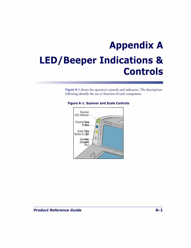
Product Reference Guide A-1
Appendix A
LED/Beeper Indications &Controls
Figure A-1 shows the operator’s controls and indicators. The descriptions following identify the use or function of each component.
Figure A-1. Scanner and Scale Controls
Speaker(Beeper)
Port
Scale ZeroButton & LED
Volume/ToneButton
ScannerLED Indicator
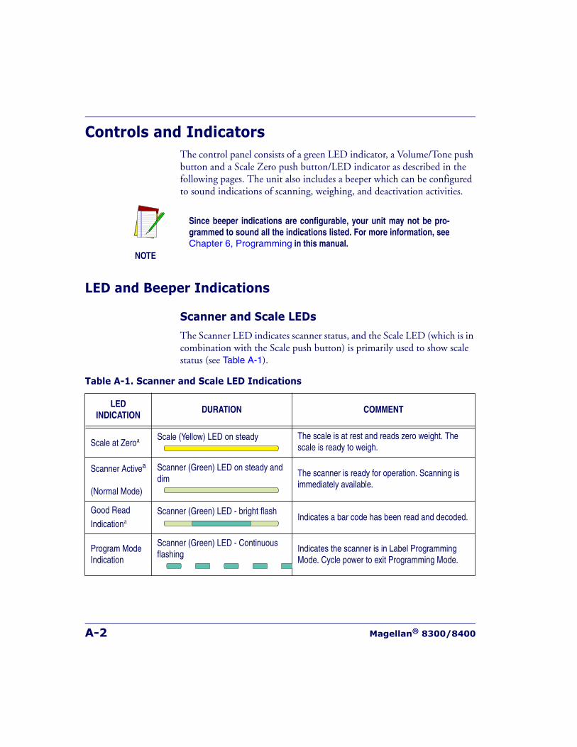
A-2 Magellan® 8300/8400
Controls and IndicatorsThe control panel consists of a green LED indicator, a Volume/Tone push button and a Scale Zero push button/LED indicator as described in the following pages. The unit also includes a beeper which can be configured to sound indications of scanning, weighing, and deactivation activities.
LED and Beeper Indications
Scanner and Scale LEDs
The Scanner LED indicates scanner status, and the Scale LED (which is in combination with the Scale push button) is primarily used to show scale status (see Table A-1).
NOTE
Since beeper indications are configurable, your unit may not be pro-grammed to sound all the indications listed. For more information, seeChapter 6, Programming in this manual.
Table A-1. Scanner and Scale LED Indications
LEDINDICATION
DURATION COMMENT
Scale at Zeroa Scale (Yellow) LED on steady The scale is at rest and reads zero weight. The scale is ready to weigh.
Scanner Activea
(Normal Mode)
Scanner (Green) LED on steady and dim
The scanner is ready for operation. Scanning is immediately available.
Good Read
IndicationaScanner (Green) LED - bright flash
Indicates a bar code has been read and decoded.
Program ModeIndication
Scanner (Green) LED - Continuous flashing
Indicates the scanner is in Label Programming Mode. Cycle power to exit Programming Mode.
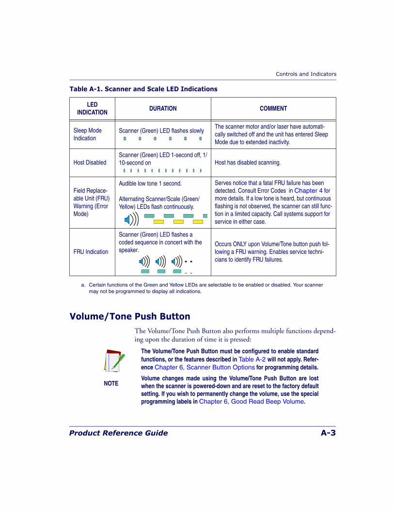
Controls and Indicators
Product Reference Guide A-3
Volume/Tone Push ButtonThe Volume/Tone Push Button also performs multiple functions depend-ing upon the duration of time it is pressed:
Sleep Mode Indication
Scanner (Green) LED flashes slowlyThe scanner motor and/or laser have automati-cally switched off and the unit has entered Sleep Mode due to extended inactivity.
Host DisabledScanner (Green) LED 1-second off, 1/10-second on Host has disabled scanning.
Field Replace-able Unit (FRU) Warning (Error Mode)
Audible low tone 1 second.
Alternating Scanner/Scale (Green/Yellow) LEDs flash continuously.
Serves notice that a fatal FRU failure has been detected. Consult Error Codes in Chapter 4 for more details. If a low tone is heard, but continuous flashing is not observed, the scanner can still func-tion in a limited capacity. Call systems support for service in either case.
FRU Indication
Scanner (Green) LED flashes a coded sequence in concert with the speaker.
Occurs ONLY upon Volume/Tone button push fol-lowing a FRU warning. Enables service techni-cians to identify FRU failures.
a. Certain functions of the Green and Yellow LEDs are selectable to be enabled or disabled. Your scanner may not be programmed to display all indications.
Table A-1. Scanner and Scale LED Indications
LEDINDICATION
DURATION COMMENT
NOTE
The Volume/Tone Push Button must be configured to enable standardfunctions, or the features described in Table A-2 will not apply. Refer-ence Chapter 6, Scanner Button Options for programming details.
Volume changes made using the Volume/Tone Push Button are lostwhen the scanner is powered-down and are reset to the factory defaultsetting. If you wish to permanently change the volume, use the specialprogramming labels in Chapter 6, Good Read Beep Volume.
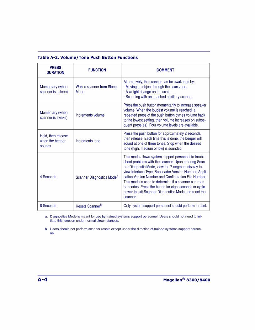
A-4 Magellan® 8300/8400
Table A-2. Volume/Tone Push Button Functions
PRESSDURATION
FUNCTION COMMENT
Momentary (when scanner is asleep)
Wakes scanner from Sleep Mode
Alternatively, the scanner can be awakened by:- Moving an object through the scan zone.- A weight change on the scale.- Scanning with an attached auxiliary scanner.
Momentary (when scanner is awake)
Increments volume
Press the push button momentarily to increase speaker volume. When the loudest volume is reached, a repeated press of the push button cycles volume back to the lowest setting, then volume increases on subse-quent press(es). Four volume levels are available.
Hold, then release when the beeper sounds
Increments tone
Press the push button for approximately 2 seconds, then release. Each time this is done, the beeper will sound at one of three tones. Stop when the desired tone (high, medium or low) is sounded.
4 Seconds Scanner Diagnostics Modea
This mode allows system support personnel to trouble-shoot problems with the scanner. Upon entering Scan-ner Diagnostic Mode, view the 7-segment display to view Interface Type, Bootloader Version Number, Appli-cation Version Number and Configuration File Number. This mode is used to determine if a scanner can read bar codes. Press the button for eight seconds or cycle power to exit Scanner Diagnostics Mode and reset the scanner.
8 Seconds Resets Scannerb Only system support personnel should perform a reset.
a. Diagnostics Mode is meant for use by trained systems support personnel. Users should not need to ini-tiate this function under normal circumstances.
b. Users should not perform scanner resets except under the direction of trained systems support person-nel.
Controls and Indicators
Product Reference Guide A-5
Scale Zero Push ButtonThe Scale Zero Push Button is used for multiple functions as listed in Table A-3.
NOTE
The Scale Zero Push Button has no function in a “scanner only”model.
The button must be configured to enable standard functions, or ScaleDiagnostics will not be an available feature. Reference Chapter 6,Scanner Button Options for programming details.
Table A-3. Scale Zero Push Button Functions
PRESSDURATION
FUNCTION COMMENT
Momentary Zero ScaleWhen programmed to do so, the yellow LED should be lit when no weight is on the scale, indicating scale at zero. If it is not, press the switch to zero the scale.
4 SecondsScale Diagnostics
Modea
This mode allows system support personnel to troubleshoot prob-lems with the scale. Momentarily press the Scale Zero Push Button or cycle power to exit Scale Diagnostics Mode.
a. Diagnostics Mode is meant for use by trained systems support personnel. Users should not need to ini-tiate this function under normal circumstances.
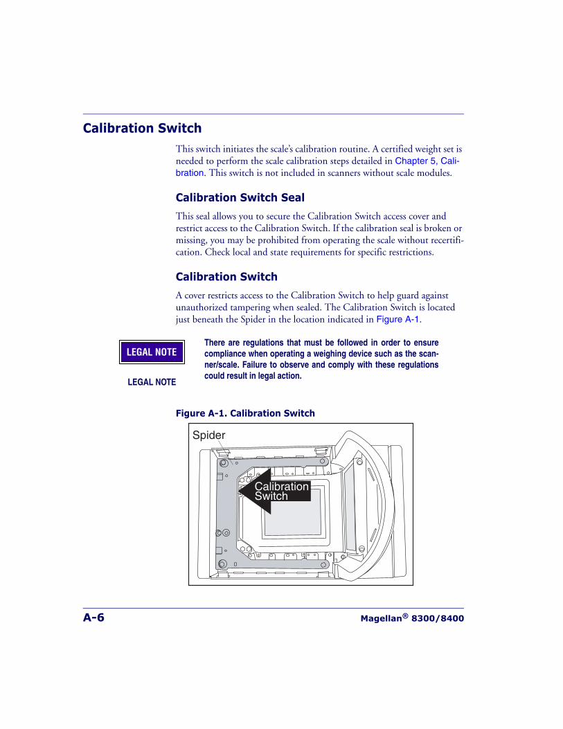
A-6 Magellan® 8300/8400
Calibration SwitchThis switch initiates the scale’s calibration routine. A certified weight set is needed to perform the scale calibration steps detailed in Chapter 5, Cali-bration. This switch is not included in scanners without scale modules.
Calibration Switch Seal
This seal allows you to secure the Calibration Switch access cover and restrict access to the Calibration Switch. If the calibration seal is broken or missing, you may be prohibited from operating the scale without recertifi-cation. Check local and state requirements for specific restrictions.
Calibration Switch
A cover restricts access to the Calibration Switch to help guard against unauthorized tampering when sealed. The Calibration Switch is located just beneath the Spider in the location indicated in Figure A-1.
Figure A-1. Calibration Switch
LEGAL NOTE
There are regulations that must be followed in order to ensurecompliance when operating a weighing device such as the scan-ner/scale. Failure to observe and comply with these regulationscould result in legal action.
LEGAL NOTE
Spider
CalibrationSwitch

Product Reference Guide B-1
Appendix B
Cable Information
IntroductionThe following pages contain pinout information, enabling you to create standard interface cables for use in interconnecting the scanner, scale, external handheld scanner, and POS terminal.
General Specifications
Wire Requirements
• Cable length should not exceed 15 feet.
• Wire gauge = Standard for RJ-45 connectors (28-26 AWG).
• If run exceeds 15 feet, we recommend 26 AWG wire size.
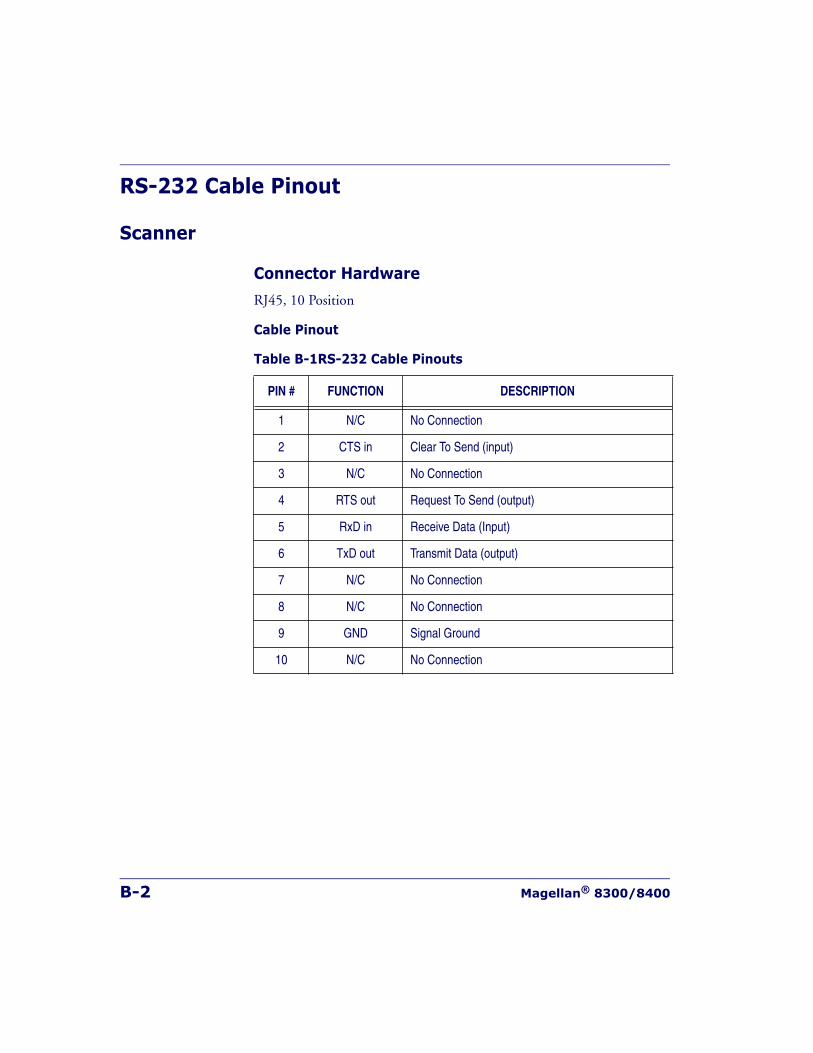
B-2 Magellan® 8300/8400
RS-232 Cable Pinout
Scanner
Connector Hardware
RJ45, 10 Position
Cable Pinout
Table B-1RS-232 Cable Pinouts
PIN # FUNCTION DESCRIPTION
1 N/C No Connection
2 CTS in Clear To Send (input)
3 N/C No Connection
4 RTS out Request To Send (output)
5 RxD in Receive Data (Input)
6 TxD out Transmit Data (output)
7 N/C No Connection
8 N/C No Connection
9 GND Signal Ground
10 N/C No Connection
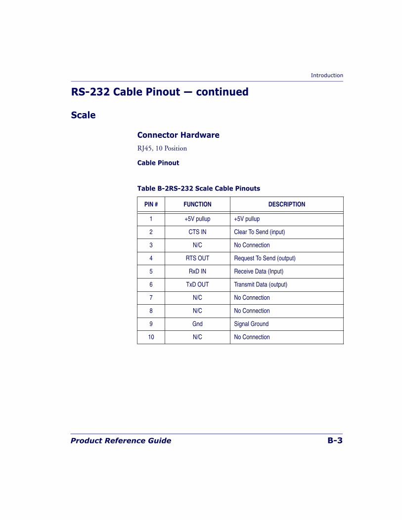
Introduction
Product Reference Guide B-3
RS-232 Cable Pinout — continued
Scale
Connector Hardware
RJ45, 10 Position
Cable Pinout
Table B-2RS-232 Scale Cable Pinouts
PIN # FUNCTION DESCRIPTION
1 +5V pullup +5V pullup
2 CTS IN Clear To Send (input)
3 N/C No Connection
4 RTS OUT Request To Send (output)
5 RxD IN Receive Data (Input)
6 TxD OUT Transmit Data (output)
7 N/C No Connection
8 N/C No Connection
9 Gnd Signal Ground
10 N/C No Connection
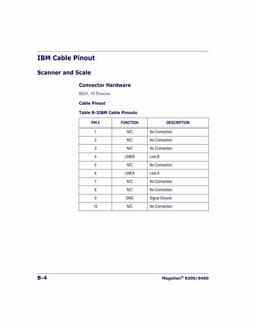
B-4 Magellan® 8300/8400
IBM Cable Pinout
Scanner and Scale
Connector Hardware
RJ45, 10 Position
Cable Pinout
Table B-3IBM Cable Pinouts
PIN # FUNCTION DESCRIPTION
1 N/C No Connection
2 N/C No Connection
3 N/C No Connection
4 LINEB Line B
5 N/C No Connection
6 LINEA Line A
7 N/C No Connection
8 N/C No Connection
9 GND Signal Ground
10 N/C No Connection
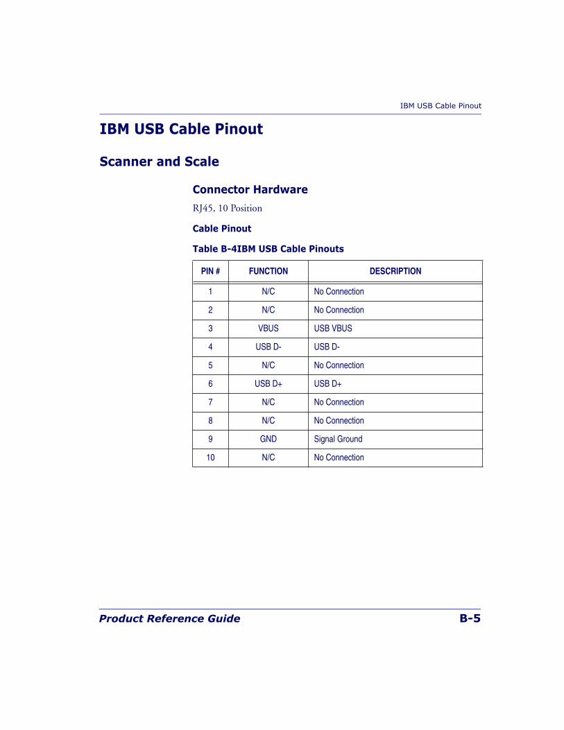
IBM USB Cable Pinout
Product Reference Guide B-5
IBM USB Cable Pinout
Scanner and Scale
Connector Hardware
RJ45, 10 Position
Cable Pinout
Table B-4IBM USB Cable Pinouts
PIN # FUNCTION DESCRIPTION
1 N/C No Connection
2 N/C No Connection
3 VBUS USB VBUS
4 USB D- USB D-
5 N/C No Connection
6 USB D+ USB D+
7 N/C No Connection
8 N/C No Connection
9 GND Signal Ground
10 N/C No Connection
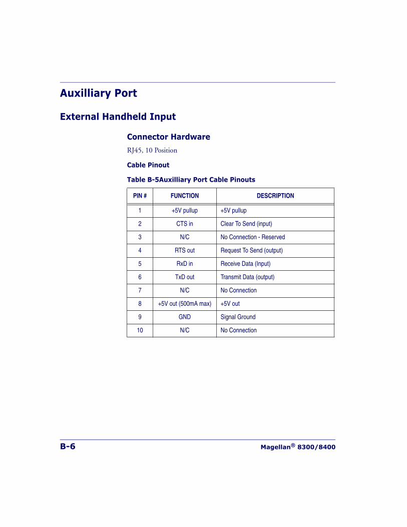
B-6 Magellan® 8300/8400
Auxilliary Port
External Handheld Input
Connector Hardware
RJ45, 10 Position
Cable Pinout
Table B-5Auxilliary Port Cable Pinouts
PIN # FUNCTION DESCRIPTION
1 +5V pullup +5V pullup
2 CTS in Clear To Send (input)
3 N/C No Connection - Reserved
4 RTS out Request To Send (output)
5 RxD in Receive Data (Input)
6 TxD out Transmit Data (output)
7 N/C No Connection
8 +5V out (500mA max) +5V out
9 GND Signal Ground
10 N/C No Connection
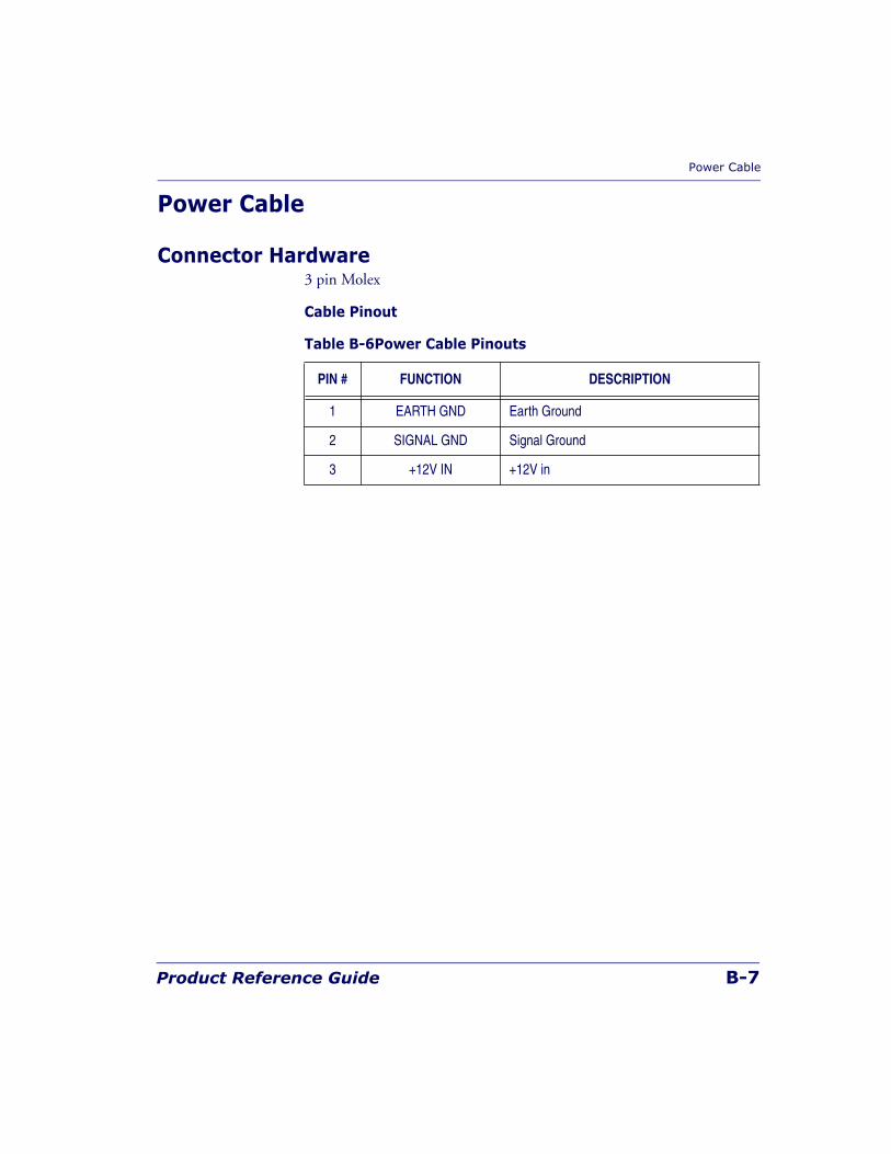
Power Cable
Product Reference Guide B-7
Power Cable
Connector Hardware3 pin Molex
Cable Pinout
Table B-6Power Cable Pinouts
PIN # FUNCTION DESCRIPTION
1 EARTH GND Earth Ground
2 SIGNAL GND Signal Ground
3 +12V IN +12V in
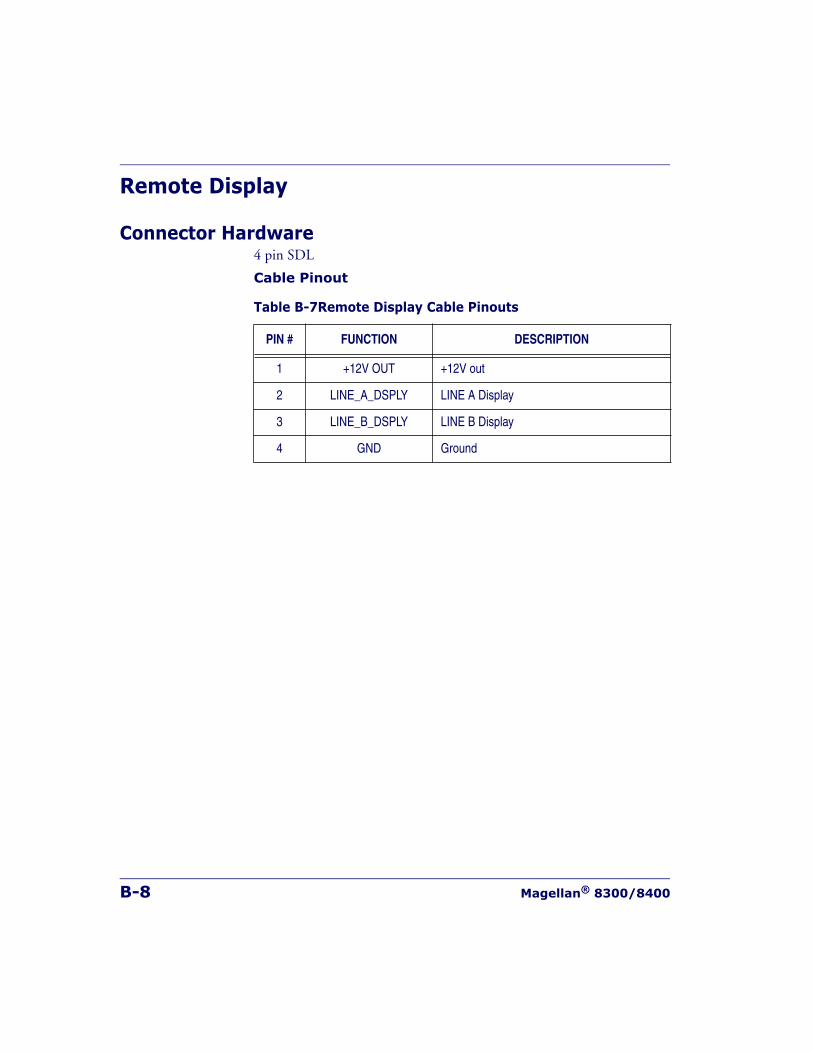
B-8 Magellan® 8300/8400
Remote Display
Connector Hardware4 pin SDL
Cable Pinout
Table B-7Remote Display Cable Pinouts
PIN # FUNCTION DESCRIPTION
1 +12V OUT +12V out
2 LINE_A_DSPLY LINE A Display
3 LINE_B_DSPLY LINE B Display
4 GND Ground
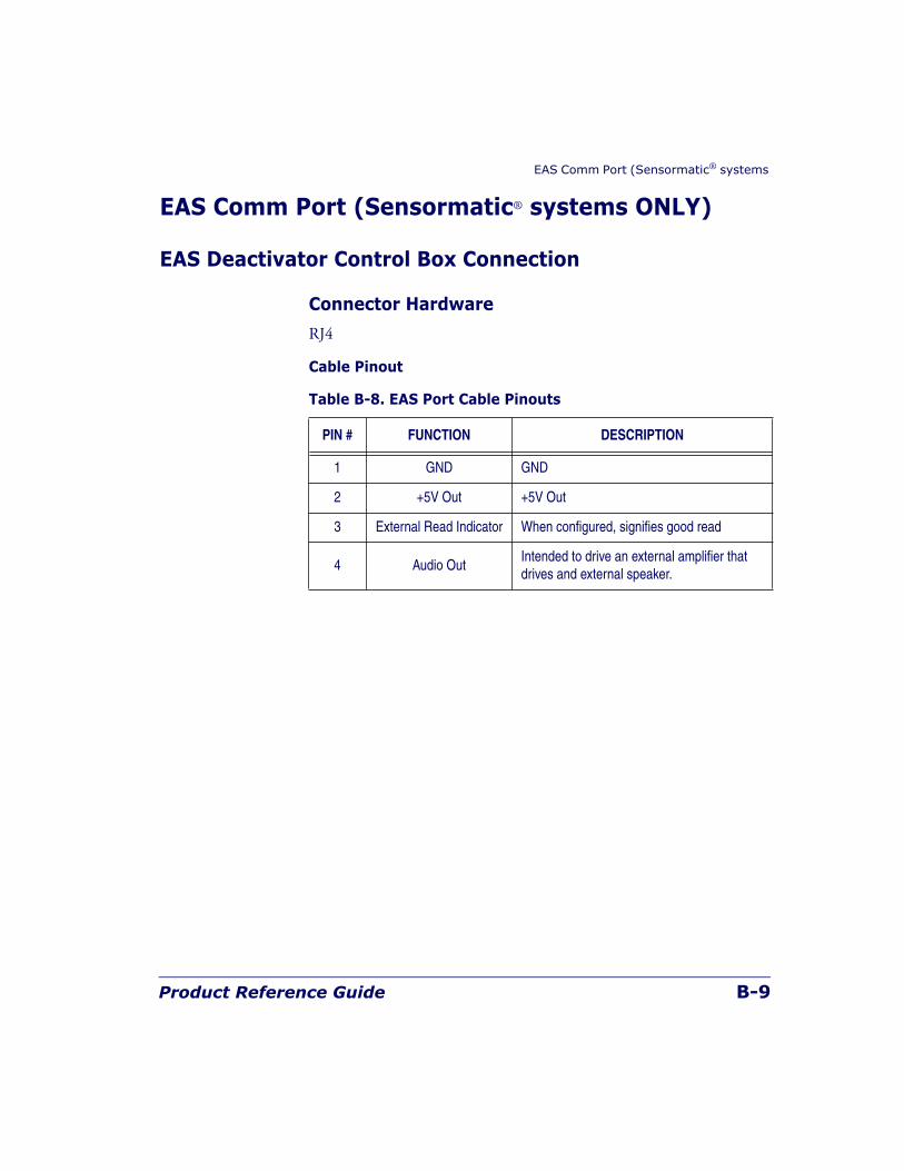
EAS Comm Port (Sensormatic® systems
Product Reference Guide B-9
EAS Comm Port (Sensormatic® systems ONLY)
EAS Deactivator Control Box Connection
Connector Hardware
RJ4
Cable Pinout
Table B-8. EAS Port Cable Pinouts
PIN # FUNCTION DESCRIPTION
1 GND GND
2 +5V Out +5V Out
3 External Read Indicator When configured, signifies good read
4 Audio OutIntended to drive an external amplifier that drives and external speaker.

B-10 Magellan® 8300/8400
NOTES

Product Reference Guide C-1
Appendix C
Keypad
Use the bar codes in this appendix to enter numbers and characters as you would select digits/characters from a keypad.
Scan your selection from the bar codes below. You’ll need to cover any unused bar codes on this and the facing page to ensure that the scanner reads only the bar code you intend to scan.
0
1
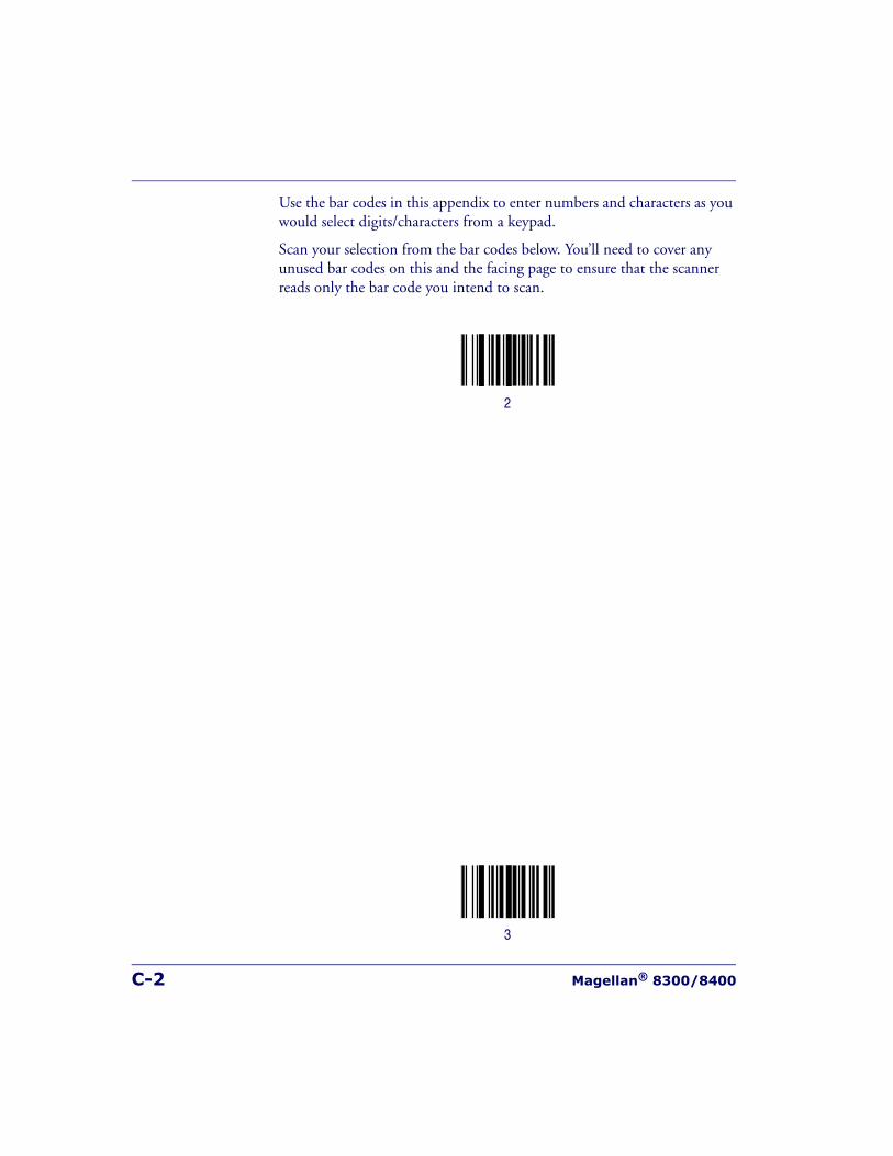
C-2 Magellan® 8300/8400
Use the bar codes in this appendix to enter numbers and characters as you would select digits/characters from a keypad.
Scan your selection from the bar codes below. You’ll need to cover any unused bar codes on this and the facing page to ensure that the scanner reads only the bar code you intend to scan.
2
3
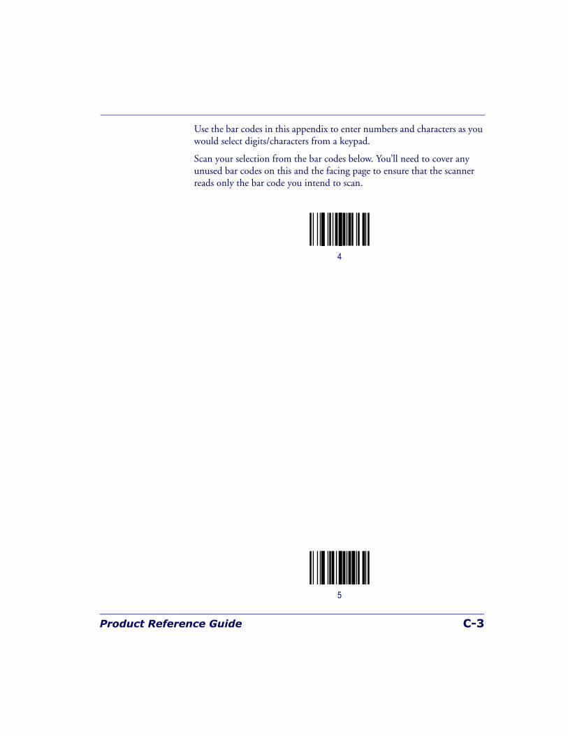
Product Reference Guide C-3
Use the bar codes in this appendix to enter numbers and characters as you would select digits/characters from a keypad.
Scan your selection from the bar codes below. You’ll need to cover any unused bar codes on this and the facing page to ensure that the scanner reads only the bar code you intend to scan.
4
5

C-4 Magellan® 8300/8400
Use the bar codes in this appendix to enter numbers and characters as you would select digits/characters from a keypad.
Scan your selection from the bar codes below. You’ll need to cover any unused bar codes on this and the facing page to ensure that the scanner reads only the bar code you intend to scan.
6
7

Product Reference Guide C-5
Use the bar codes in this appendix to enter numbers and characters as you would select digits/characters from a keypad.
Scan your selection from the bar codes below. You’ll need to cover any unused bar codes on this and the facing page to ensure that the scanner reads only the bar code you intend to scan.
8
9

C-6 Magellan® 8300/8400
Use the bar codes in this appendix to enter numbers and characters as you would select digits/characters from a keypad.
Scan your selection from the bar codes below. You’ll need to cover any unused bar codes on this and the facing page to ensure that the scanner reads only the bar code you intend to scan.
A
B

Product Reference Guide C-7
Use the bar codes in this appendix to enter numbers and characters as you would select digits/characters from a keypad.
Scan your selection from the bar codes below. You’ll need to cover any unused bar codes on this and the facing page to ensure that the scanner reads only the bar code you intend to scan.
C
D
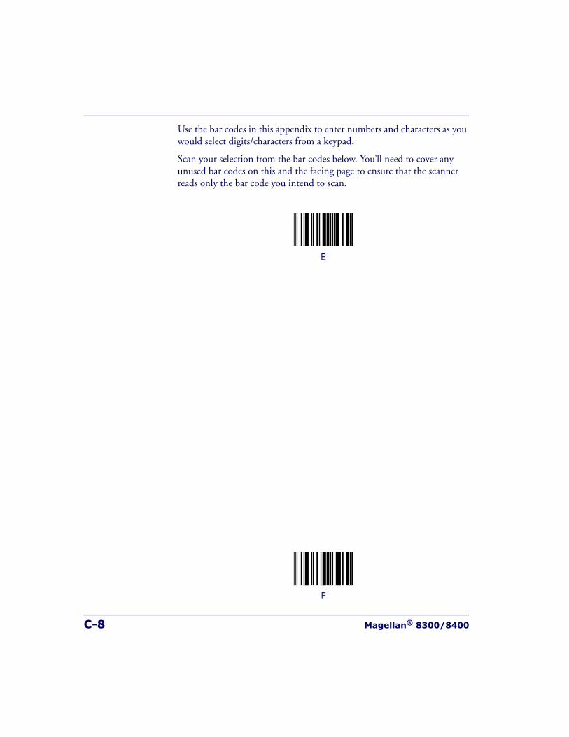
C-8 Magellan® 8300/8400
Use the bar codes in this appendix to enter numbers and characters as you would select digits/characters from a keypad.
Scan your selection from the bar codes below. You’ll need to cover any unused bar codes on this and the facing page to ensure that the scanner reads only the bar code you intend to scan.
E
F
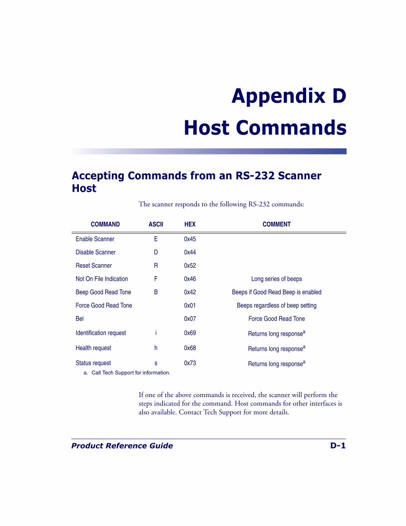
Product Reference Guide D-1
Appendix D
Host Commands
Accepting Commands from an RS-232 Scanner Host
The scanner responds to the following RS-232 commands:
If one of the above commands is received, the scanner will perform the steps indicated for the command. Host commands for other interfaces is also available. Contact Tech Support for more details.
COMMAND ASCII HEX COMMENT
Enable Scanner E 0x45
Disable Scanner D 0x44
Reset Scanner R 0x52
Not On File Indication F 0x46 Long series of beeps
Beep Good Read Tone B 0x42 Beeps if Good Read Beep is enabled
Force Good Read Tone 0x01 Beeps regardless of beep setting
Bel 0x07 Force Good Read Tone
Identification request i 0x69 Returns long responsea
Health request h 0x68 Returns long responsea
Status request s 0x73 Returns long responsea
a. Call Tech Support for information.

D-2 Magellan® 8300/8400
NOTES

Product Reference Guide E-1
Appendix E
Keyboard Function KeyMappings
Keyboard Model Cross ReferenceTable E-2 summarizes the keyboard models, their defined protocol, scancode set, and some unique features. The remaining tables in this chapter provide the function key maps associated with each of the scancode sets.
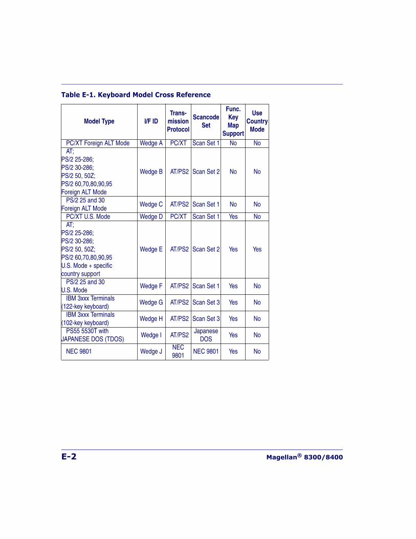
E-2 Magellan® 8300/8400
Table E-1. Keyboard Model Cross Reference
Model Type I/F IDTrans-
missionProtocol
ScancodeSet
Func.KeyMap
Support
UseCountry
Mode
PC/XT Foreign ALT Mode Wedge A PC/XT Scan Set 1 No NoAT;
PS/2 25-286; PS/2 30-286; PS/2 50, 50Z; PS/2 60,70,80,90,95Foreign ALT Mode
Wedge B AT/PS2 Scan Set 2 No No
PS/2 25 and 30 Foreign ALT Mode
Wedge C AT/PS2 Scan Set 1 No No
PC/XT U.S. Mode Wedge D PC/XT Scan Set 1 Yes NoAT;
PS/2 25-286; PS/2 30-286; PS/2 50, 50Z; PS/2 60,70,80,90,95U.S. Mode + specificcountry support
Wedge E AT/PS2 Scan Set 2 Yes Yes
PS/2 25 and 30U.S. Mode
Wedge F AT/PS2 Scan Set 1 Yes No
IBM 3xxx Terminals (122-key keyboard)
Wedge G AT/PS2 Scan Set 3 Yes No
IBM 3xxx Terminals(102-key keyboard)
Wedge H AT/PS2 Scan Set 3 Yes No
PS55 5530T withJAPANESE DOS (TDOS)
Wedge I AT/PS2Japanese
DOSYes No
NEC 9801 Wedge JNEC9801
NEC 9801 Yes No
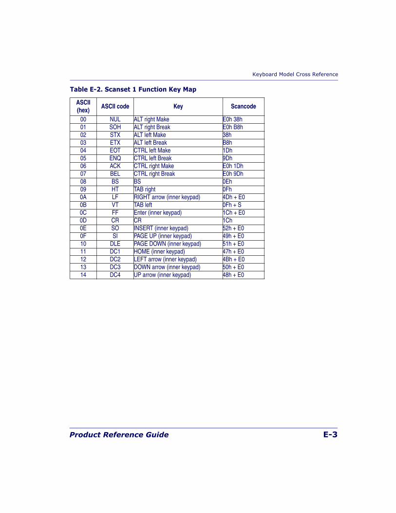
Keyboard Model Cross Reference
Product Reference Guide E-3
Table E-2. Scanset 1 Function Key Map
ASCII(hex)
ASCII code Key Scancode
00 NUL ALT right Make E0h 38h01 SOH ALT right Break E0h B8h02 STX ALT left Make 38h 03 ETX ALT left Break B8h04 EOT CTRL left Make 1Dh05 ENQ CTRL left Break 9Dh06 ACK CTRL right Make E0h 1Dh07 BEL CTRL right Break E0h 9Dh08 BS BS 0Eh09 HT TAB right 0Fh0A LF RIGHT arrow (inner keypad) 4Dh + E00B VT TAB left 0Fh + S0C FF Enter (inner keypad) 1Ch + E00D CR CR 1Ch0E SO INSERT (inner keypad) 52h + E00F SI PAGE UP (inner keypad) 49h + E010 DLE PAGE DOWN (inner keypad) 51h + E011 DC1 HOME (inner keypad) 47h + E012 DC2 LEFT arrow (inner keypad) 4Bh + E013 DC3 DOWN arrow (inner keypad) 50h + E014 DC4 UP arrow (inner keypad) 48h + E0
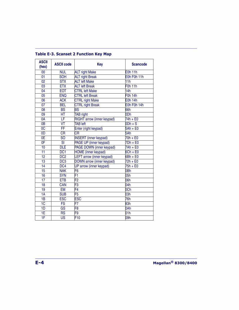
E-4 Magellan® 8300/8400
Table E-3. Scanset 2 Function Key Map
ASCII(hex)
ASCII code Key Scancode
00 NUL ALT right Make E0h 11h01 SOH ALT right Break E0h F0h 11h02 STX ALT left Make 11h 03 ETX ALT left Break F0h 11h04 EOT CTRL left Make 14h05 ENQ CTRL left Break F0h 14h06 ACK CTRL right Make E0h 14h07 BEL CTRL right Break E0h F0h 14h08 BS BS 66h09 HT TAB right 0Dh0A LF RIGHT arrow (inner keypad) 74h + E00B VT TAB left 0Dh + S0C FF Enter (right keypad) 5Ah + E00D CR CR 5Ah0E SO INSERT (inner keypad) 70h + E00F SI PAGE UP (inner keypad) 7Dh + E010 DLE PAGE DOWN (inner keypad) 7Ah + E011 DC1 HOME (inner keypad) 6Ch + E012 DC2 LEFT arrow (inner keypad) 6Bh + E013 DC3 DOWN arrow (inner keypad) 72h + E014 DC4 UP arrow (inner keypad) 75h + E015 NAK F6 0Bh16 SYN F1 05h17 ETB F2 06h 18 CAN F3 04h19 EM F4 0Ch1A SUB F5 03h1B ESC ESC 76h1C FS F7 83h1D GS F8 0Ah1E RS F9 01h1F US F10 09h
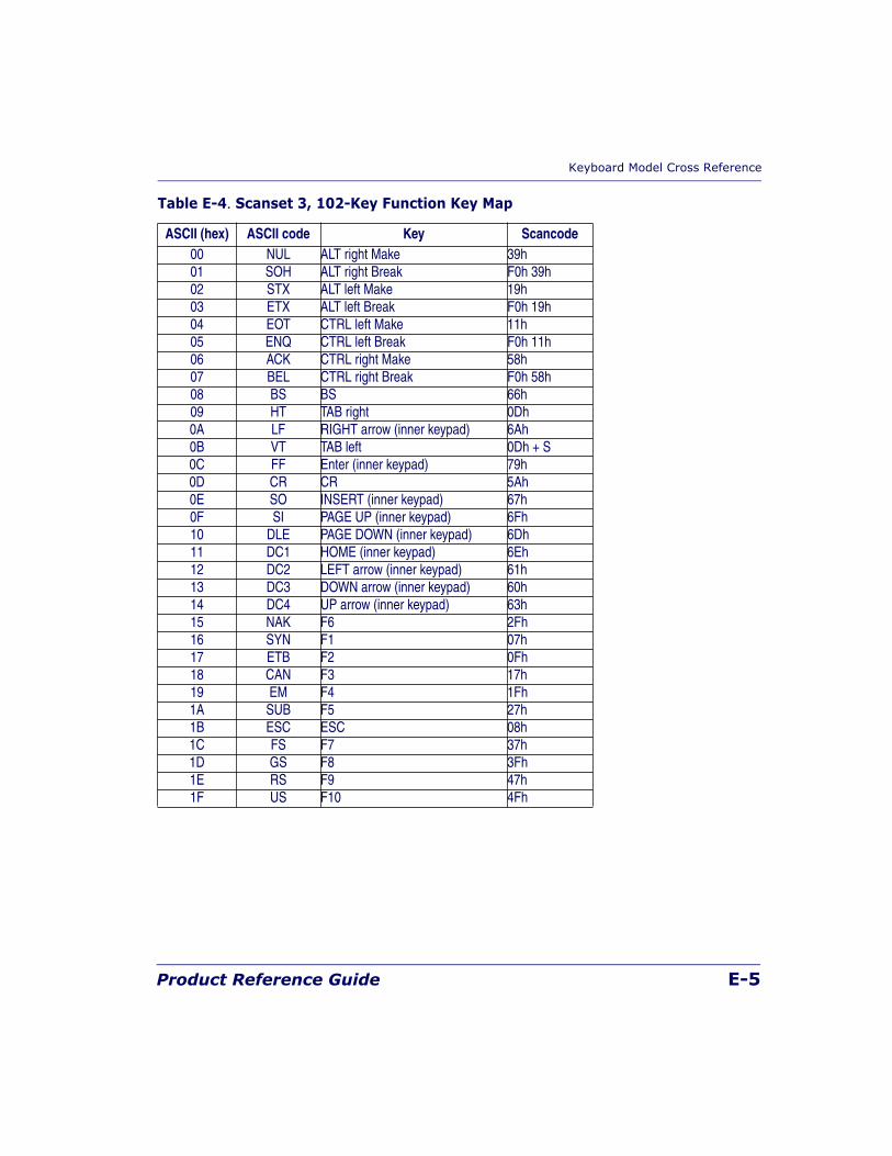
Keyboard Model Cross Reference
Product Reference Guide E-5
Table E-4. Scanset 3, 102-Key Function Key Map
ASCII (hex) ASCII code Key Scancode00 NUL ALT right Make 39h01 SOH ALT right Break F0h 39h02 STX ALT left Make 19h 03 ETX ALT left Break F0h 19h04 EOT CTRL left Make 11h05 ENQ CTRL left Break F0h 11h06 ACK CTRL right Make 58h07 BEL CTRL right Break F0h 58h08 BS BS 66h09 HT TAB right 0Dh0A LF RIGHT arrow (inner keypad) 6Ah0B VT TAB left 0Dh + S0C FF Enter (inner keypad) 79h0D CR CR 5Ah0E SO INSERT (inner keypad) 67h0F SI PAGE UP (inner keypad) 6Fh10 DLE PAGE DOWN (inner keypad) 6Dh11 DC1 HOME (inner keypad) 6Eh12 DC2 LEFT arrow (inner keypad) 61h13 DC3 DOWN arrow (inner keypad) 60h14 DC4 UP arrow (inner keypad) 63h15 NAK F6 2Fh16 SYN F1 07h17 ETB F2 0Fh 18 CAN F3 17h19 EM F4 1Fh1A SUB F5 27h1B ESC ESC 08h1C FS F7 37h1D GS F8 3Fh1E RS F9 47h1F US F10 4Fh
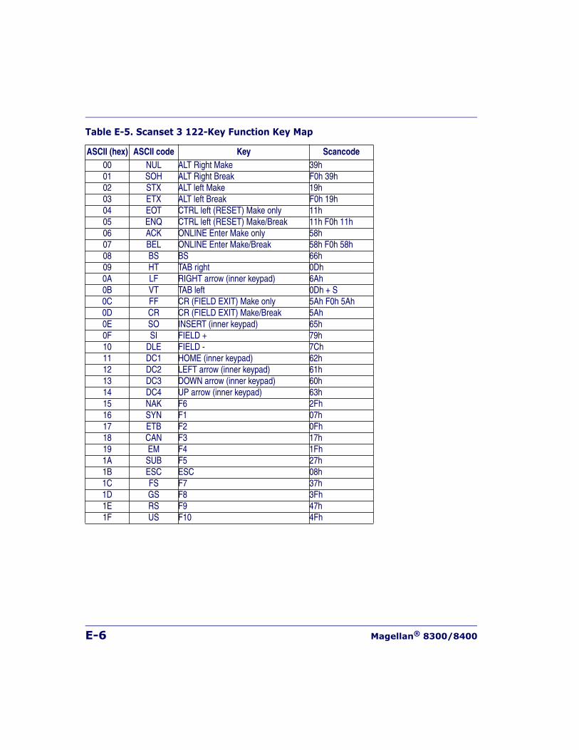
E-6 Magellan® 8300/8400
Table E-5. Scanset 3 122-Key Function Key Map
ASCII (hex) ASCII code Key Scancode00 NUL ALT Right Make 39h01 SOH ALT Right Break F0h 39h02 STX ALT left Make 19h 03 ETX ALT left Break F0h 19h04 EOT CTRL left (RESET) Make only 11h05 ENQ CTRL left (RESET) Make/Break 11h F0h 11h06 ACK ONLINE Enter Make only 58h07 BEL ONLINE Enter Make/Break 58h F0h 58h08 BS BS 66h09 HT TAB right 0Dh0A LF RIGHT arrow (inner keypad) 6Ah0B VT TAB left 0Dh + S0C FF CR (FIELD EXIT) Make only 5Ah F0h 5Ah0D CR CR (FIELD EXIT) Make/Break 5Ah0E SO INSERT (inner keypad) 65h0F SI FIELD + 79h10 DLE FIELD - 7Ch11 DC1 HOME (inner keypad) 62h12 DC2 LEFT arrow (inner keypad) 61h13 DC3 DOWN arrow (inner keypad) 60h14 DC4 UP arrow (inner keypad) 63h15 NAK F6 2Fh16 SYN F1 07h17 ETB F2 0Fh 18 CAN F3 17h19 EM F4 1Fh1A SUB F5 27h1B ESC ESC 08h1C FS F7 37h1D GS F8 3Fh1E RS F9 47h1F US F10 4Fh
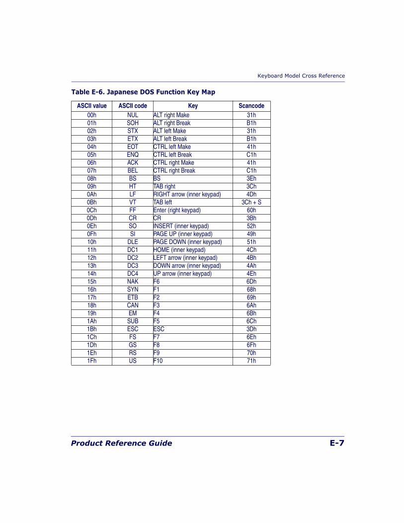
Keyboard Model Cross Reference
Product Reference Guide E-7
Table E-6. Japanese DOS Function Key Map
ASCII value ASCII code Key Scancode00h NUL ALT right Make 31h01h SOH ALT right Break B1h02h STX ALT left Make 31h03h ETX ALT left Break B1h04h EOT CTRL left Make 41h05h ENQ CTRL left Break C1h06h ACK CTRL right Make 41h07h BEL CTRL right Break C1h08h BS BS 3Eh09h HT TAB right 3Ch0Ah LF RIGHT arrow (inner keypad) 4Dh0Bh VT TAB left 3Ch + S0Ch FF Enter (right keypad) 60h0Dh CR CR 3Bh0Eh SO INSERT (inner keypad) 52h0Fh SI PAGE UP (inner keypad) 49h10h DLE PAGE DOWN (inner keypad) 51h11h DC1 HOME (inner keypad) 4Ch12h DC2 LEFT arrow (inner keypad) 4Bh13h DC3 DOWN arrow (inner keypad) 4Ah14h DC4 UP arrow (inner keypad) 4Eh15h NAK F6 6Dh16h SYN F1 68h17h ETB F2 69h 18h CAN F3 6Ah19h EM F4 6Bh1Ah SUB F5 6Ch1Bh ESC ESC 3Dh1Ch FS F7 6Eh1Dh GS F8 6Fh1Eh RS F9 70h1Fh US F10 71h
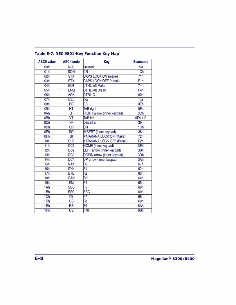
E-8 Magellan® 8300/8400
Table E-7. NEC 9801-Key Function Key Map
ASCII value ASCII code Key Scancode00h NUL unused n/a01h SOH CR 1Ch02h STX CAPS LOCK ON (make) 71h03h ETX CAPS LOCK OFF (break) F1h04h EOT CTRL left Make 74h05h ENQ CTRL left Break F4h06h ACK CTRL-C 60h07h BEL n/a n/a08h BS BS 0Eh09h HT TAB right 0Fh0Ah LF RIGHT arrow (inner keypad) 3Ch0Bh VT TAB left 0Fh + S0Ch FF DELETE 39h0Dh CR CR 1Ch0Eh SO INSERT (inner keypad) 38h0Fh SI KATAKANA LOCK ON (Make) 72h10h DLE KATAKANA LOCK OFF (Break) F2h11h DC1 HOME (inner keypad) 3Eh12h DC2 LEFT arrow (inner keypad) 3Bh13h DC3 DOWN arrow (inner keypad) 3Dh14h DC4 UP arrow (inner keypad) 3Ah15h NAK F6 67h16h SYN F1 62h17h ETB F2 63h 18h CAN F3 64h19h EM F4 65h1Ah SUB F5 66h1Bh ESC ESC 00h1Ch FS F7 68h1Dh GS F8 69h1Eh RS F9 6Ah1Fh US F10 6Bh
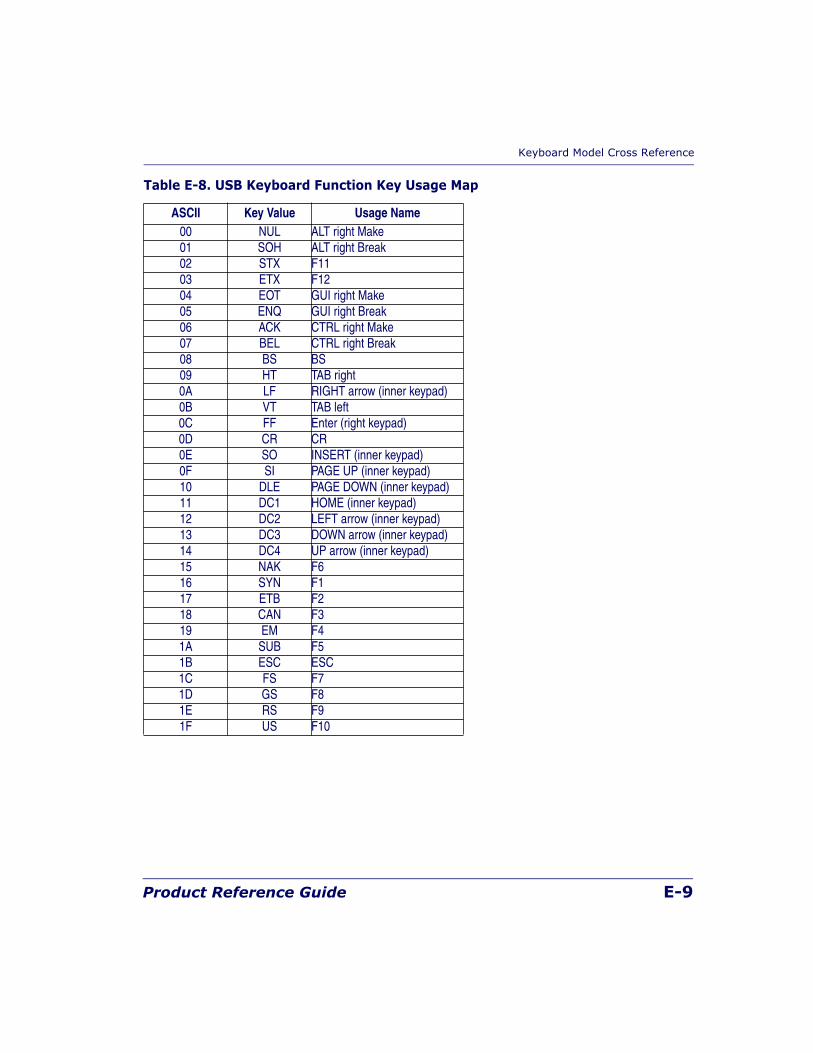
Keyboard Model Cross Reference
Product Reference Guide E-9
Table E-8. USB Keyboard Function Key Usage Map
ASCII Key Value Usage Name00 NUL ALT right Make01 SOH ALT right Break02 STX F1103 ETX F1204 EOT GUI right Make05 ENQ GUI right Break06 ACK CTRL right Make07 BEL CTRL right Break08 BS BS09 HT TAB right0A LF RIGHT arrow (inner keypad)0B VT TAB left0C FF Enter (right keypad)0D CR CR0E SO INSERT (inner keypad)0F SI PAGE UP (inner keypad)10 DLE PAGE DOWN (inner keypad)11 DC1 HOME (inner keypad)12 DC2 LEFT arrow (inner keypad)13 DC3 DOWN arrow (inner keypad)14 DC4 UP arrow (inner keypad)15 NAK F616 SYN F117 ETB F218 CAN F319 EM F41A SUB F51B ESC ESC1C FS F71D GS F81E RS F91F US F10

E-10 Magellan® 8300/8400
NOTES
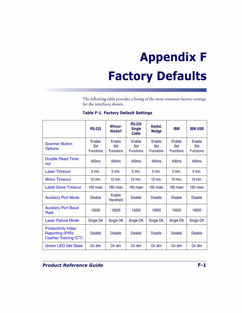
Product Reference Guide F-1
Appendix F
Factory Defaults
The following table provides a listing of the most common factory settings for the interfaces shown.
Table F-1. Factory Default Settings
RS-232Wincor- Nixdorf
RS-232SingleCable
Keybd. Wedge
IBM IBM USB
Scanner Button Options
Enable Std
Functions
Enable Std
Functions
Enable Std
Functions
Enable Std
Functions
Enable Std
Functions
Enable Std
Functions
Double Read Time-out
400ms 400ms 400ms 400ms 400ms 400ms
Laser Timeout 5 min. 5 min. 5 min. 5 min. 5 min. 5 min.
Motor Timeout 10 min. 10 min. 10 min. 10 min. 10 min. 10 min.
Label Gone Timeout 160 msec 160 msec 160 msec 160 msec 160 msec 160 msec
Auxiliary Port Mode DisableEnable
HandheldDisable Disable Disable Disable
Auxiliary Port Baud Rate
19200 19200 19200 19200 19200 19200
Laser Failure Mode Single OK Single OK Single OK Single OK Single OK Single OK
Productivity Index Reporting (PIR)/Cashier Training (CT)
Disable Disable Disable Disable Disable Disable
Green LED Idle State On dim On dim On dim On dim On dim On dim
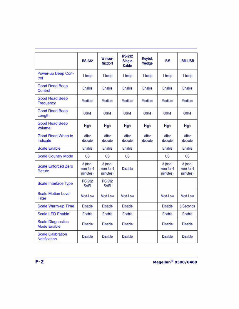
F-2 Magellan® 8300/8400
Power-up Beep Con-trol
1 beep 1 beep 1 beep 1 beep 1 beep 1 beep
Good Read Beep Control
Enable Enable Enable Enable Enable Enable
Good Read Beep Frequency
Medium Medium Medium Medium Medium Medium
Good Read Beep Length
80ms 80ms 80ms 80ms 80ms 80ms
Good Read Beep Volume
High High High High High High
Good Read When to Indicate
Afterdecode
Afterdecode
Afterdecode
Afterdecode
Afterdecode
Afterdecode
Scale Enable Enable Enable Enable Enable Enable
Scale Country Mode US US US US US
Scale Enforced Zero Return
3 (non-zero for 4 minutes)
3 (non-zero for 4 minutes)
Disable3 (non-
zero for 4 minutes)
3 (non-zero for 4 minutes)
Scale Interface TypeRS-232
SASIRS-232
SASI
Scale Motion Level Filter
Med-Low Med-Low Med-Low Med-Low Med-Low
Scale Warm-up Time Disable Disable Disable Disable 5 Seconds
Scale LED Enable Enable Enable Enable Enable Enable
Scale Diagnostics Mode Enable
Disable Disable Disable Disable Disable
Scale Calibration Notification
Disable Disable Disable Disable Disable
RS-232Wincor- Nixdorf
RS-232SingleCable
Keybd. Wedge
IBM IBM USB
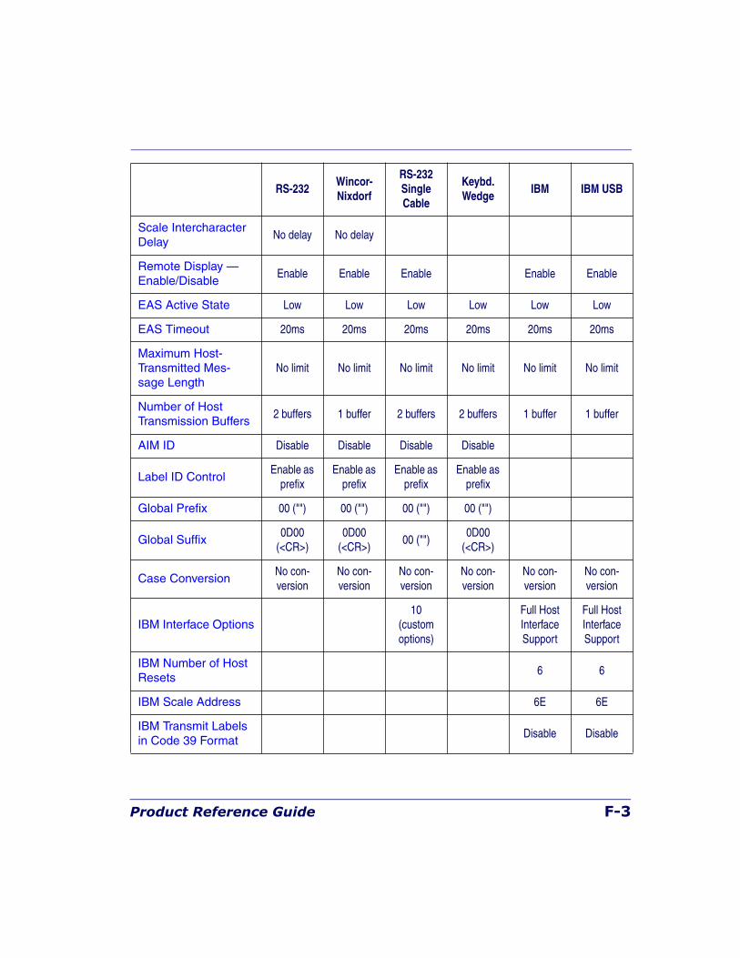
Product Reference Guide F-3
Scale Intercharacter Delay
No delay No delay
Remote Display — Enable/Disable
Enable Enable Enable Enable Enable
EAS Active State Low Low Low Low Low Low
EAS Timeout 20ms 20ms 20ms 20ms 20ms 20ms
Maximum Host-Transmitted Mes-sage Length
No limit No limit No limit No limit No limit No limit
Number of Host Transmission Buffers
2 buffers 1 buffer 2 buffers 2 buffers 1 buffer 1 buffer
AIM ID Disable Disable Disable Disable
Label ID ControlEnable as
prefixEnable as
prefixEnable as
prefixEnable as
prefix
Global Prefix 00 ("") 00 ("") 00 ("") 00 ("")
Global Suffix0D00
(<CR>)0D00
(<CR>)00 ("")
0D00(<CR>)
Case ConversionNo con-version
No con-version
No con-version
No con-version
No con-version
No con-version
IBM Interface Options10
(customoptions)
Full HostInterface Support
Full HostInterface Support
IBM Number of Host Resets
6 6
IBM Scale Address 6E 6E
IBM Transmit Labels in Code 39 Format
Disable Disable
RS-232Wincor- Nixdorf
RS-232SingleCable
Keybd. Wedge
IBM IBM USB
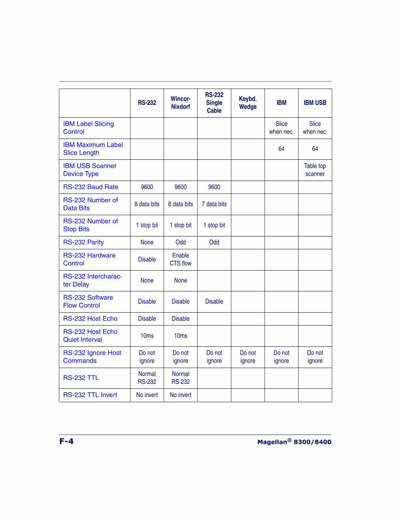
F-4 Magellan® 8300/8400
IBM Label Slicing Control
Slicewhen nec.
Slicewhen nec.
IBM Maximum Label Slice Length
64 64
IBM USB Scanner Device Type
Table top scanner
RS-232 Baud Rate 9600 9600 9600
RS-232 Number of Data Bits
8 data bits 8 data bits 7 data bits
RS-232 Number of Stop Bits
1 stop bit 1 stop bit 1 stop bit
RS-232 Parity None Odd Odd
RS-232 Hardware Control
DisableEnable
CTS flow
RS-232 Intercharac-ter Delay
None None
RS-232 Software Flow Control
Disable Disable Disable
RS-232 Host Echo Disable Disable
RS-232 Host Echo Quiet Interval
10ms 10ms
RS-232 Ignore Host Commands
Do not ignore
Do not ignore
Do not ignore
Do not ignore
Do not ignore
Do not ignore
RS-232 TTLNormal RS-232
Normal RS-232
RS-232 TTL Invert No invert No invert
RS-232Wincor- Nixdorf
RS-232SingleCable
Keybd. Wedge
IBM IBM USB
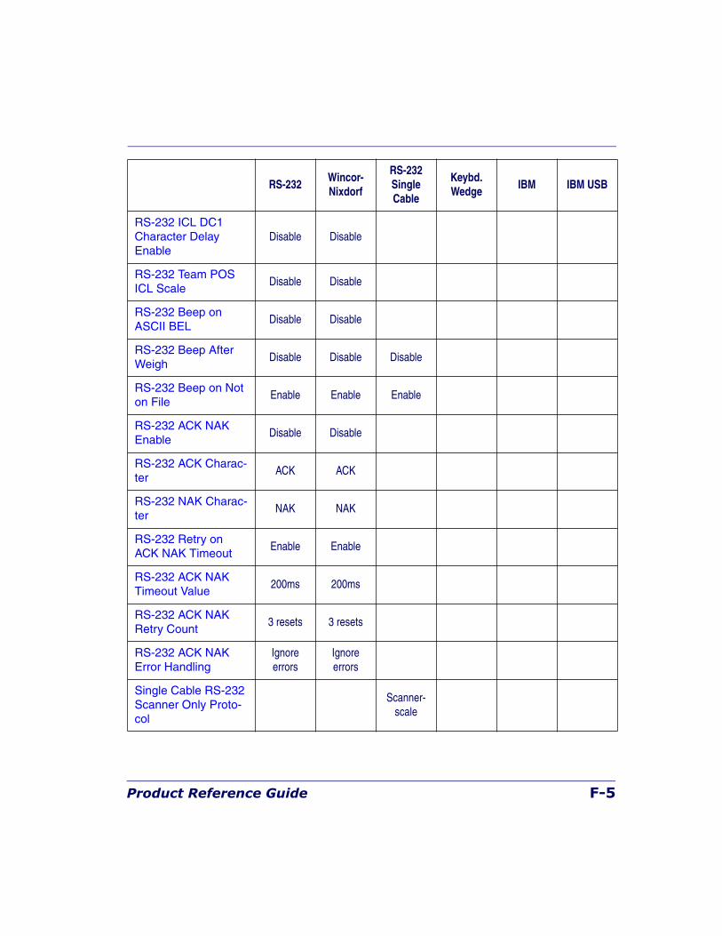
Product Reference Guide F-5
RS-232 ICL DC1 Character Delay Enable
Disable Disable
RS-232 Team POS ICL Scale
Disable Disable
RS-232 Beep on ASCII BEL
Disable Disable
RS-232 Beep After Weigh
Disable Disable Disable
RS-232 Beep on Not on File
Enable Enable Enable
RS-232 ACK NAK Enable
Disable Disable
RS-232 ACK Charac-ter
ACK ACK
RS-232 NAK Charac-ter
NAK NAK
RS-232 Retry on ACK NAK Timeout
Enable Enable
RS-232 ACK NAK Timeout Value
200ms 200ms
RS-232 ACK NAK Retry Count
3 resets 3 resets
RS-232 ACK NAK Error Handling
Ignoreerrors
Ignoreerrors
Single Cable RS-232 Scanner Only Proto-col
Scanner-scale
RS-232Wincor- Nixdorf
RS-232SingleCable
Keybd. Wedge
IBM IBM USB
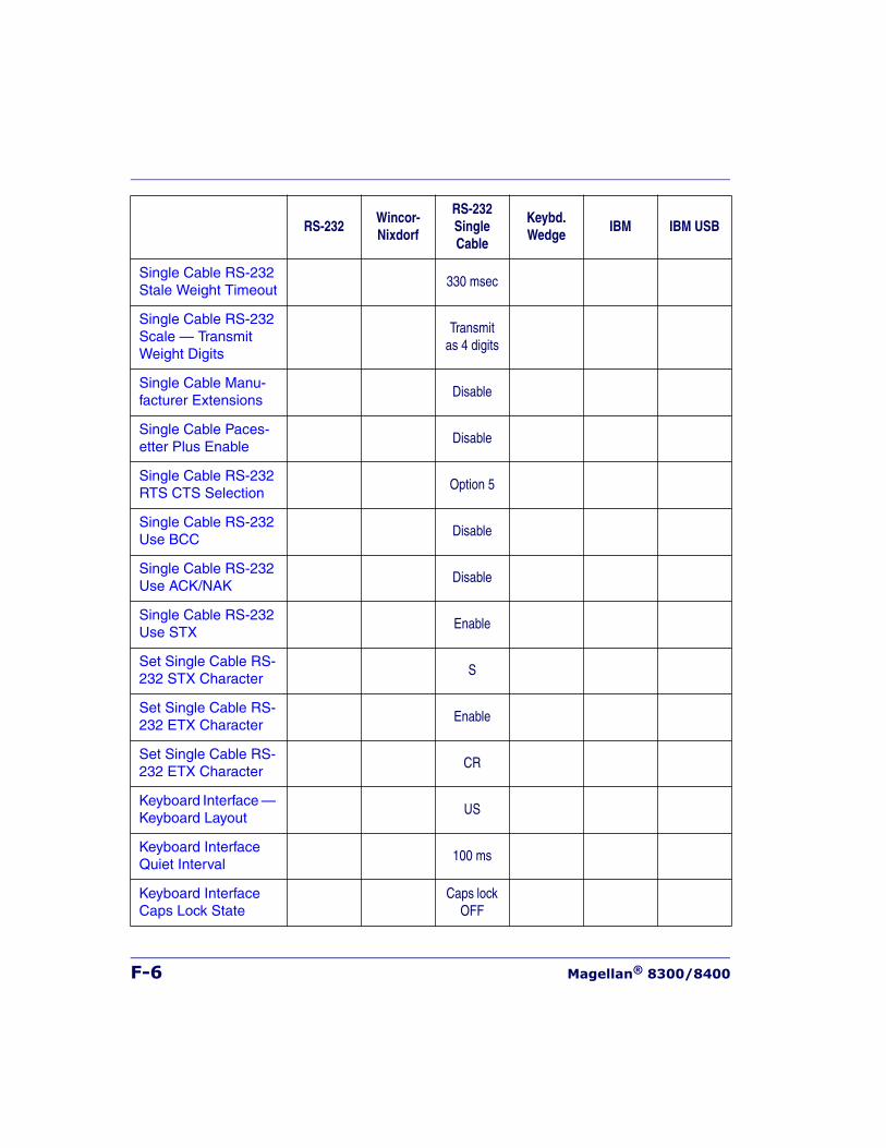
F-6 Magellan® 8300/8400
Single Cable RS-232 Stale Weight Timeout
330 msec
Single Cable RS-232 Scale — Transmit Weight Digits
Transmit as 4 digits
Single Cable Manu-facturer Extensions
Disable
Single Cable Paces-etter Plus Enable
Disable
Single Cable RS-232 RTS CTS Selection
Option 5
Single Cable RS-232 Use BCC
Disable
Single Cable RS-232 Use ACK/NAK
Disable
Single Cable RS-232 Use STX
Enable
Set Single Cable RS-232 STX Character
S
Set Single Cable RS-232 ETX Character
Enable
Set Single Cable RS-232 ETX Character
CR
Keyboard Interface — Keyboard Layout
US
Keyboard Interface Quiet Interval
100 ms
Keyboard Interface Caps Lock State
Caps lock OFF
RS-232Wincor- Nixdorf
RS-232SingleCable
Keybd. Wedge
IBM IBM USB
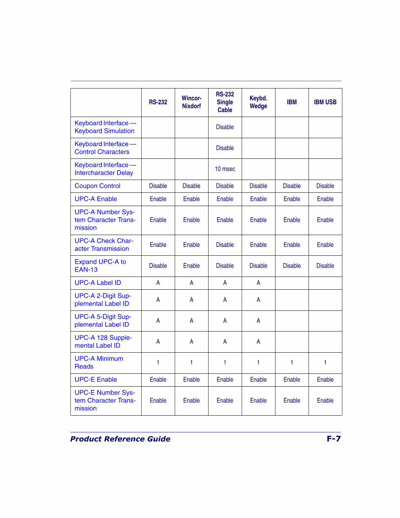
Product Reference Guide F-7
Keyboard Interface — Keyboard Simulation
Disable
Keyboard Interface — Control Characters
Disable
Keyboard Interface — Intercharacter Delay
10 msec
Coupon Control Disable Disable Disable Disable Disable Disable
UPC-A Enable Enable Enable Enable Enable Enable Enable
UPC-A Number Sys-tem Character Trans-mission
Enable Enable Enable Enable Enable Enable
UPC-A Check Char-acter Transmission
Enable Enable Disable Enable Enable Enable
Expand UPC-A to EAN-13
Disable Enable Disable Disable Disable Disable
UPC-A Label ID A A A A
UPC-A 2-Digit Sup-plemental Label ID
A A A A
UPC-A 5-Digit Sup-plemental Label ID
A A A A
UPC-A 128 Supple-mental Label ID
A A A A
UPC-A Minimum Reads
1 1 1 1 1 1
UPC-E Enable Enable Enable Enable Enable Enable Enable
UPC-E Number Sys-tem Character Trans-mission
Enable Enable Enable Enable Enable Enable
RS-232Wincor- Nixdorf
RS-232SingleCable
Keybd. Wedge
IBM IBM USB
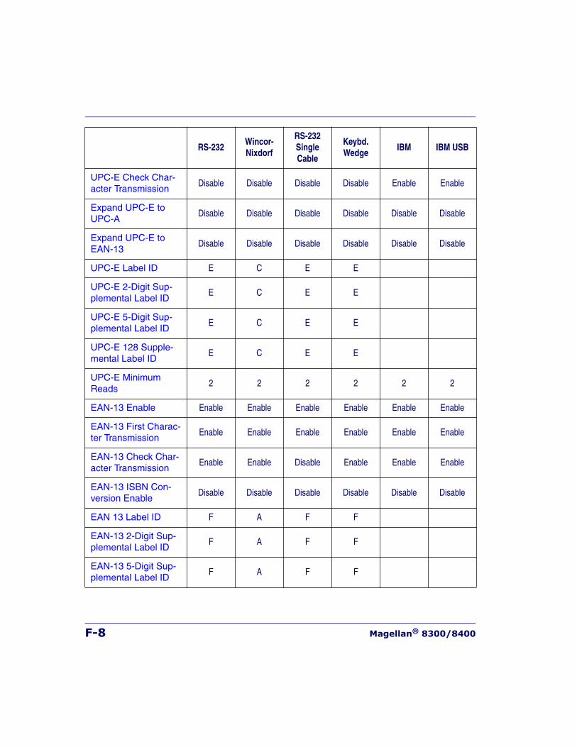
F-8 Magellan® 8300/8400
UPC-E Check Char-acter Transmission
Disable Disable Disable Disable Enable Enable
Expand UPC-E to UPC-A
Disable Disable Disable Disable Disable Disable
Expand UPC-E to EAN-13
Disable Disable Disable Disable Disable Disable
UPC-E Label ID E C E E
UPC-E 2-Digit Sup-plemental Label ID
E C E E
UPC-E 5-Digit Sup-plemental Label ID
E C E E
UPC-E 128 Supple-mental Label ID
E C E E
UPC-E Minimum Reads
2 2 2 2 2 2
EAN-13 Enable Enable Enable Enable Enable Enable Enable
EAN-13 First Charac-ter Transmission
Enable Enable Enable Enable Enable Enable
EAN-13 Check Char-acter Transmission
Enable Enable Disable Enable Enable Enable
EAN-13 ISBN Con-version Enable
Disable Disable Disable Disable Disable Disable
EAN 13 Label ID F A F F
EAN-13 2-Digit Sup-plemental Label ID
F A F F
EAN-13 5-Digit Sup-plemental Label ID
F A F F
RS-232Wincor- Nixdorf
RS-232SingleCable
Keybd. Wedge
IBM IBM USB
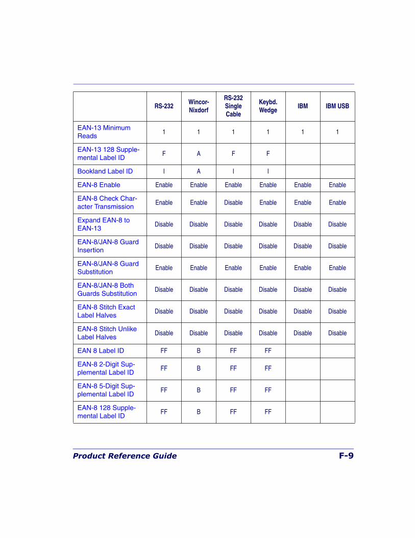
Product Reference Guide F-9
EAN-13 Minimum Reads
1 1 1 1 1 1
EAN-13 128 Supple-mental Label ID
F A F F
Bookland Label ID I A I I
EAN-8 Enable Enable Enable Enable Enable Enable Enable
EAN-8 Check Char-acter Transmission
Enable Enable Disable Enable Enable Enable
Expand EAN-8 to EAN-13
Disable Disable Disable Disable Disable Disable
EAN-8/JAN-8 Guard Insertion
Disable Disable Disable Disable Disable Disable
EAN-8/JAN-8 Guard Substitution
Enable Enable Enable Enable Enable Enable
EAN-8/JAN-8 Both Guards Substitution
Disable Disable Disable Disable Disable Disable
EAN-8 Stitch Exact Label Halves
Disable Disable Disable Disable Disable Disable
EAN-8 Stitch Unlike Label Halves
Disable Disable Disable Disable Disable Disable
EAN 8 Label ID FF B FF FF
EAN-8 2-Digit Sup-plemental Label ID
FF B FF FF
EAN-8 5-Digit Sup-plemental Label ID
FF B FF FF
EAN-8 128 Supple-mental Label ID
FF B FF FF
RS-232Wincor- Nixdorf
RS-232SingleCable
Keybd. Wedge
IBM IBM USB
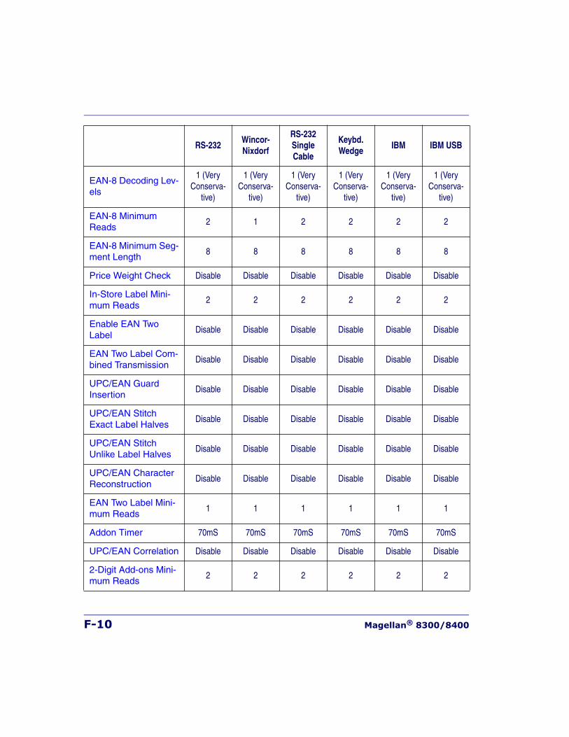
F-10 Magellan® 8300/8400
EAN-8 Decoding Lev-els
1 (Very Conserva-
tive)
1 (Very Conserva-
tive)
1 (Very Conserva-
tive)
1 (Very Conserva-
tive)
1 (Very Conserva-
tive)
1 (Very Conserva-
tive)
EAN-8 Minimum Reads
2 1 2 2 2 2
EAN-8 Minimum Seg-ment Length
8 8 8 8 8 8
Price Weight Check Disable Disable Disable Disable Disable Disable
In-Store Label Mini-mum Reads
2 2 2 2 2 2
Enable EAN Two Label
Disable Disable Disable Disable Disable Disable
EAN Two Label Com-bined Transmission
Disable Disable Disable Disable Disable Disable
UPC/EAN Guard Insertion
Disable Disable Disable Disable Disable Disable
UPC/EAN Stitch Exact Label Halves
Disable Disable Disable Disable Disable Disable
UPC/EAN Stitch Unlike Label Halves
Disable Disable Disable Disable Disable Disable
UPC/EAN Character Reconstruction
Disable Disable Disable Disable Disable Disable
EAN Two Label Mini-mum Reads
1 1 1 1 1 1
Addon Timer 70mS 70mS 70mS 70mS 70mS 70mS
UPC/EAN Correlation Disable Disable Disable Disable Disable Disable
2-Digit Add-ons Mini-mum Reads
2 2 2 2 2 2
RS-232Wincor- Nixdorf
RS-232SingleCable
Keybd. Wedge
IBM IBM USB
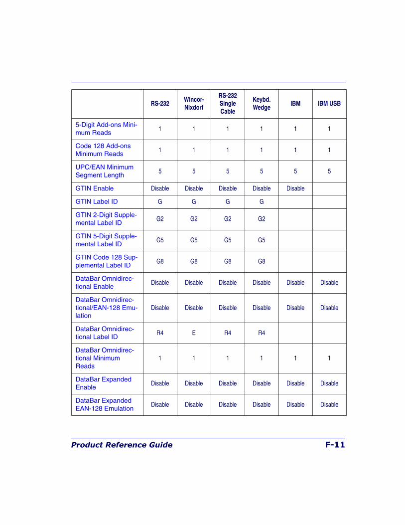
Product Reference Guide F-11
5-Digit Add-ons Mini-mum Reads
1 1 1 1 1 1
Code 128 Add-ons Minimum Reads
1 1 1 1 1 1
UPC/EAN Minimum Segment Length
5 5 5 5 5 5
GTIN Enable Disable Disable Disable Disable Disable
GTIN Label ID G G G G
GTIN 2-Digit Supple-mental Label ID
G2 G2 G2 G2
GTIN 5-Digit Supple-mental Label ID
G5 G5 G5 G5
GTIN Code 128 Sup-plemental Label ID
G8 G8 G8 G8
DataBar Omnidirec-tional Enable
Disable Disable Disable Disable Disable Disable
DataBar Omnidirec-tional/EAN-128 Emu-lation
Disable Disable Disable Disable Disable Disable
DataBar Omnidirec-tional Label ID
R4 E R4 R4
DataBar Omnidirec-tional Minimum Reads
1 1 1 1 1 1
DataBar Expanded Enable
Disable Disable Disable Disable Disable Disable
DataBar Expanded EAN-128 Emulation
Disable Disable Disable Disable Disable Disable
RS-232Wincor- Nixdorf
RS-232SingleCable
Keybd. Wedge
IBM IBM USB
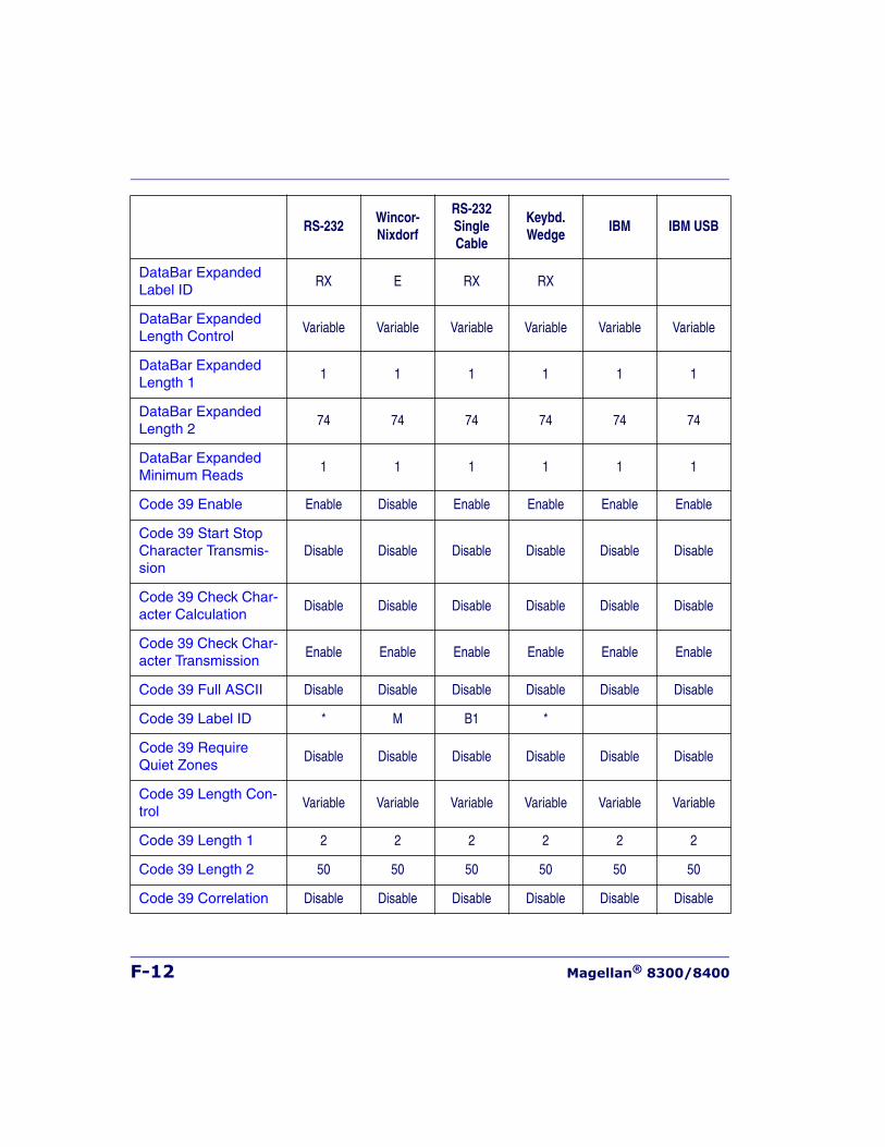
F-12 Magellan® 8300/8400
DataBar Expanded Label ID
RX E RX RX
DataBar Expanded Length Control
Variable Variable Variable Variable Variable Variable
DataBar Expanded Length 1
1 1 1 1 1 1
DataBar Expanded Length 2
74 74 74 74 74 74
DataBar Expanded Minimum Reads
1 1 1 1 1 1
Code 39 Enable Enable Disable Enable Enable Enable Enable
Code 39 Start Stop Character Transmis-sion
Disable Disable Disable Disable Disable Disable
Code 39 Check Char-acter Calculation
Disable Disable Disable Disable Disable Disable
Code 39 Check Char-acter Transmission
Enable Enable Enable Enable Enable Enable
Code 39 Full ASCII Disable Disable Disable Disable Disable Disable
Code 39 Label ID * M B1 *
Code 39 Require Quiet Zones
Disable Disable Disable Disable Disable Disable
Code 39 Length Con-trol
Variable Variable Variable Variable Variable Variable
Code 39 Length 1 2 2 2 2 2 2
Code 39 Length 2 50 50 50 50 50 50
Code 39 Correlation Disable Disable Disable Disable Disable Disable
RS-232Wincor- Nixdorf
RS-232SingleCable
Keybd. Wedge
IBM IBM USB
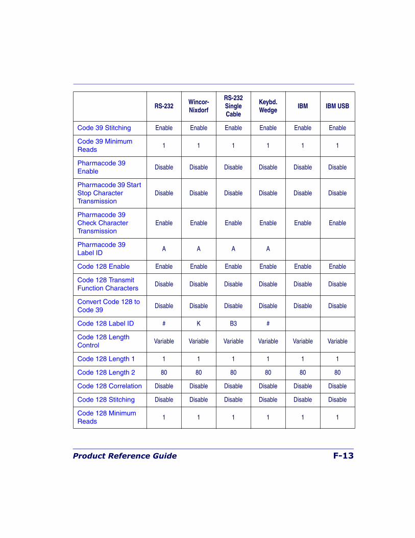
Product Reference Guide F-13
Code 39 Stitching Enable Enable Enable Enable Enable Enable
Code 39 Minimum Reads
1 1 1 1 1 1
Pharmacode 39 Enable
Disable Disable Disable Disable Disable Disable
Pharmacode 39 Start Stop Character Transmission
Disable Disable Disable Disable Disable Disable
Pharmacode 39 Check Character Transmission
Enable Enable Enable Enable Enable Enable
Pharmacode 39 Label ID
A A A A
Code 128 Enable Enable Enable Enable Enable Enable Enable
Code 128 Transmit Function Characters
Disable Disable Disable Disable Disable Disable
Convert Code 128 to Code 39
Disable Disable Disable Disable Disable Disable
Code 128 Label ID # K B3 #
Code 128 Length Control
Variable Variable Variable Variable Variable Variable
Code 128 Length 1 1 1 1 1 1 1
Code 128 Length 2 80 80 80 80 80 80
Code 128 Correlation Disable Disable Disable Disable Disable Disable
Code 128 Stitching Disable Disable Disable Disable Disable Disable
Code 128 Minimum Reads
1 1 1 1 1 1
RS-232Wincor- Nixdorf
RS-232SingleCable
Keybd. Wedge
IBM IBM USB
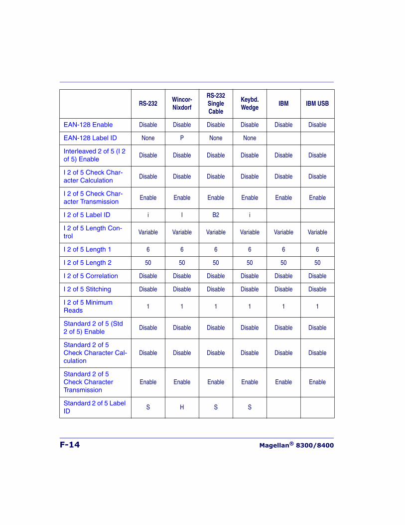
F-14 Magellan® 8300/8400
EAN-128 Enable Disable Disable Disable Disable Disable Disable
EAN-128 Label ID None P None None
Interleaved 2 of 5 (I 2 of 5) Enable
Disable Disable Disable Disable Disable Disable
I 2 of 5 Check Char-acter Calculation
Disable Disable Disable Disable Disable Disable
I 2 of 5 Check Char-acter Transmission
Enable Enable Enable Enable Enable Enable
I 2 of 5 Label ID i I B2 i
I 2 of 5 Length Con-trol
Variable Variable Variable Variable Variable Variable
I 2 of 5 Length 1 6 6 6 6 6 6
I 2 of 5 Length 2 50 50 50 50 50 50
I 2 of 5 Correlation Disable Disable Disable Disable Disable Disable
I 2 of 5 Stitching Disable Disable Disable Disable Disable Disable
I 2 of 5 Minimum Reads
1 1 1 1 1 1
Standard 2 of 5 (Std 2 of 5) Enable
Disable Disable Disable Disable Disable Disable
Standard 2 of 5 Check Character Cal-culation
Disable Disable Disable Disable Disable Disable
Standard 2 of 5 Check Character Transmission
Enable Enable Enable Enable Enable Enable
Standard 2 of 5 Label ID
S H S S
RS-232Wincor- Nixdorf
RS-232SingleCable
Keybd. Wedge
IBM IBM USB
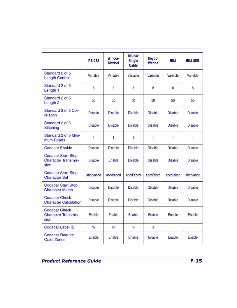
Product Reference Guide F-15
Standard 2 of 5 Length Control
Variable Variable Variable Variable Variable Variable
Standard 2 of 5 Length 1
8 8 8 8 8 8
Standard 2 of 5 Length 2
50 50 50 50 50 50
Standard 2 of 5 Cor-relation
Disable Disable Disable Disable Disable Disable
Standard 2 of 5 Stitching
Disable Disable Disable Disable Disable Disable
Standard 2 of 5 Mini-mum Reads
1 1 1 1 1 1
Codabar Enable Disable Disable Disable Disable Disable Disable
Codabar Start Stop Character Transmis-sion
Disable Enable Disable Disable Disable Disable
Codabar Start Stop Character Set
abcd/abcd abcd/abcd abcd/abcd abcd/abcd abcd/abcd abcd/abcd
Codabar Start Stop Character Match
Disable Disable Disable Disable Disable Disable
Codabar Check Character Calculation
Disable Disable Disable Disable Disable Disable
Codabar Check Character Transmis-sion
Enable Enable Enable Enable Enable Enable
Codabar Label ID % N % %
Codabar Require Quiet Zones
Enable Enable Enable Enable Enable Enable
RS-232Wincor- Nixdorf
RS-232SingleCable
Keybd. Wedge
IBM IBM USB
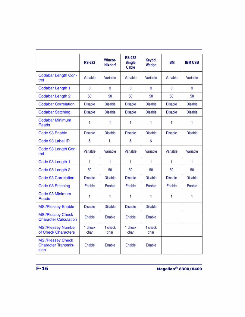
F-16 Magellan® 8300/8400
Codabar Length Con-trol
Variable Variable Variable Variable Variable Variable
Codabar Length 1 3 3 3 3 3 3
Codabar Length 2 50 50 50 50 50 50
Codabar Correlation Disable Disable Disable Disable Disable Disable
Codabar Stitching Disable Disable Disable Disable Disable Disable
Codabar Minimum Reads
1 1 1 1 1 1
Code 93 Enable Disable Disable Disable Disable Disable Disable
Code 93 Label ID & L & &
Code 93 Length Con-trol
Variable Variable Variable Variable Variable Variable
Code 93 Length 1 1 1 1 1 1 1
Code 93 Length 2 50 50 50 50 50 50
Code 93 Correlation Disable Disable Disable Disable Disable Disable
Code 93 Stitching Enable Enable Enable Enable Enable Enable
Code 93 Minimum Reads
1 1 1 1 1 1
MSI/Plessey Enable Disable Disable Disable Disable
MSI/Plessey Check Character Calculation
Enable Enable Enable Enable
MSI/Plessey Number of Check Characters
1 check char
1 check char
1 check char
1 check char
MSI/Plessey Check Character Transmis-sion
Enable Enable Enable Enable
RS-232Wincor- Nixdorf
RS-232SingleCable
Keybd. Wedge
IBM IBM USB
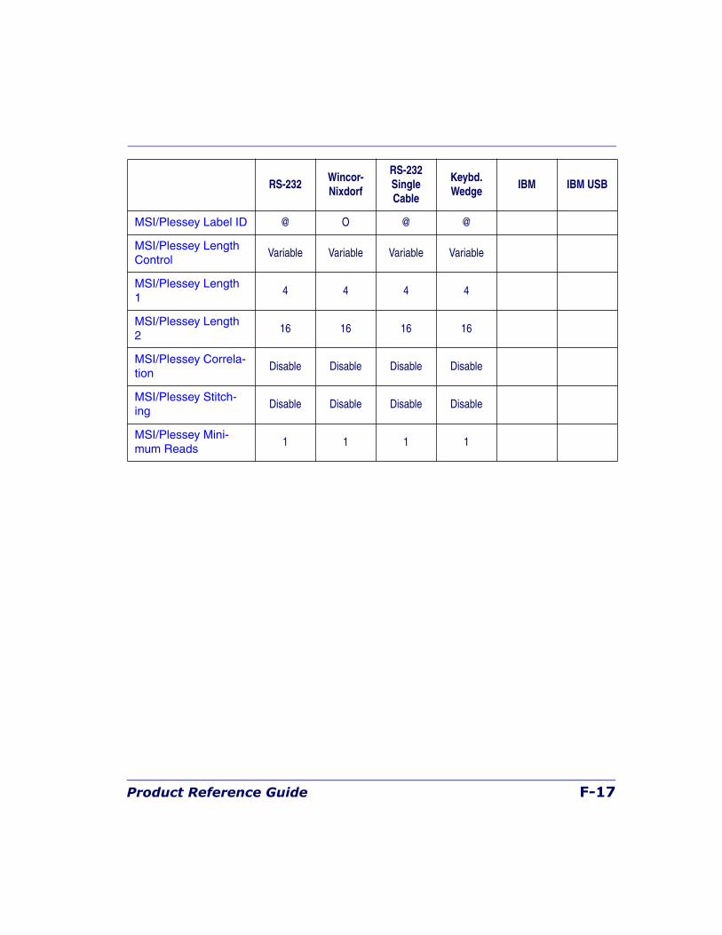
Product Reference Guide F-17
MSI/Plessey Label ID @ O @ @
MSI/Plessey Length Control
Variable Variable Variable Variable
MSI/Plessey Length 1
4 4 4 4
MSI/Plessey Length 2
16 16 16 16
MSI/Plessey Correla-tion
Disable Disable Disable Disable
MSI/Plessey Stitch-ing
Disable Disable Disable Disable
MSI/Plessey Mini-mum Reads
1 1 1 1
RS-232Wincor- Nixdorf
RS-232SingleCable
Keybd. Wedge
IBM IBM USB

F-18 Magellan® 8300/8400
NOTES

Product Reference Guide G-1
Appendix G
Handheld Data FormatRequirements
This appendix provides application notes to describe the general format of data that can be accepted by the scanner through the auxilliary port as transmitted from a handheld scanner.
Handheld Data Format Requirements General• 9600 bps, 8 data bits, 2 stop bits, no parity.
• RTS is used to "bracket" the data received from the handheld: RTS must be asserted high during data transmission, and de-asserted after label transmission is complete. No other flow control mecha-nisms are required or supported. The de-assertion of the RTS signal must occur no sooner than 200 microseconds and no greater than 50 milliseconds from the complete transmission of the last character of the transmitted data.
• The time between character transmission can be no longer than 50 milliseconds.
• Symbologies requiring fixed lengths (UPC/EAN) will enforce length requirements for validation of the label.
• Handheld scanner will be required to transmit start and stop charac-ters for Codabar and Code 39 labels.
• Appropriate industrial length requirements will be enforced (if con-figured) for validation of the label.
• Maximum label lengths will be enforced for label validation (i.e. labels longer than the maximum label size will not be validated).
• Standard Datalogic formats generally use a single prefix character. The specific formats are provided below.
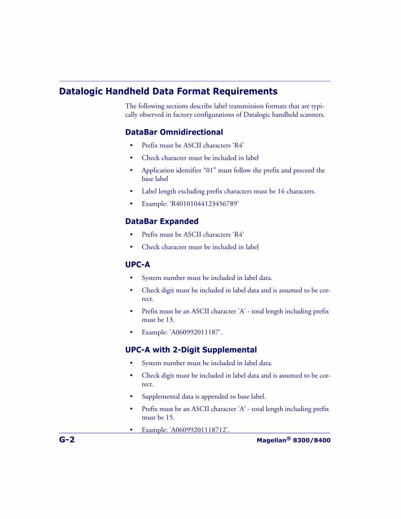
G-2 Magellan® 8300/8400
Datalogic Handheld Data Format RequirementsThe following sections describe label transmission formats that are typi-cally observed in factory configurations of Datalogic handheld scanners.
DataBar Omnidirectional
• Prefix must be ASCII characters ‘R4’
• Check character must be included in label
• Application identifier “01” must follow the prefix and preceed the base label
• Label length excluding prefix characters must be 16 characters.
• Example: ‘R40101044123456789’
DataBar Expanded
• Prefix must be ASCII characters ‘R4’
• Check character must be included in label
UPC-A
• System number must be included in label data.
• Check digit must be included in label data and is assumed to be cor-rect.
• Prefix must be an ASCII character 'A' - total length including prefix must be 13.
• Example: 'A060992011187'.
UPC-A with 2-Digit Supplemental
• System number must be included in label data.
• Check digit must be included in label data and is assumed to be cor-rect.
• Supplemental data is appended to base label.
• Prefix must be an ASCII character 'A' - total length including prefix must be 15.
• Example: 'A06099201118712'.
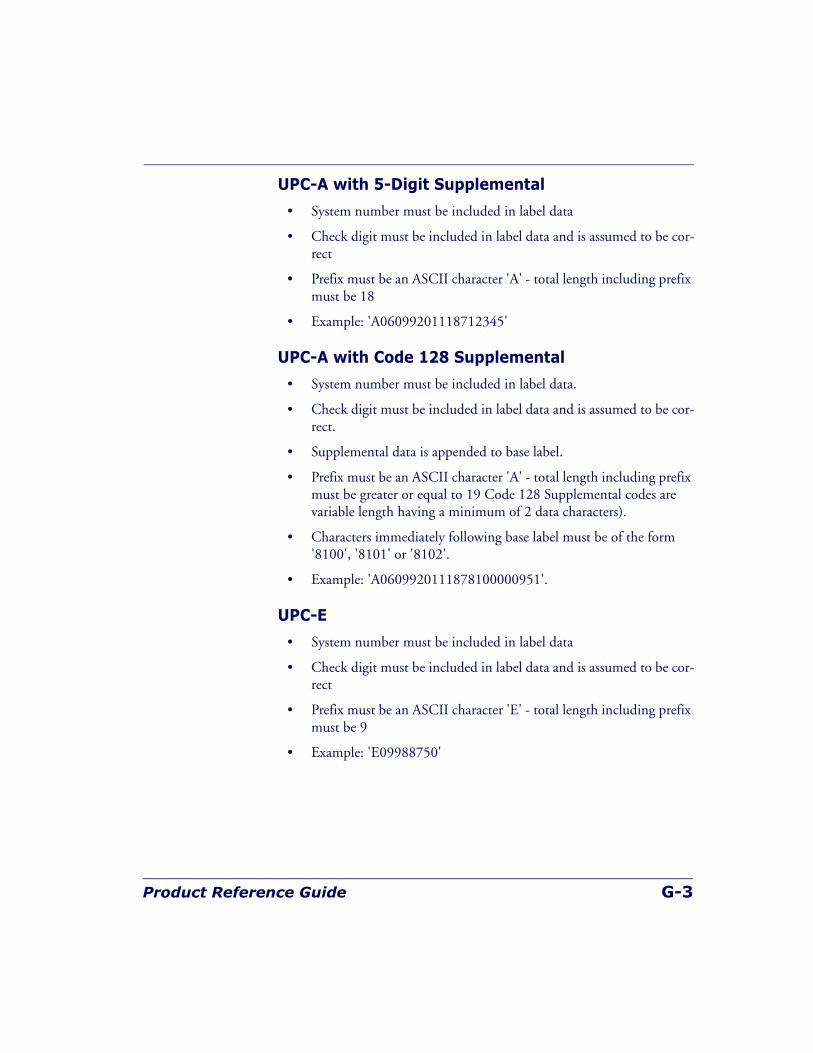
Product Reference Guide G-3
UPC-A with 5-Digit Supplemental
• System number must be included in label data
• Check digit must be included in label data and is assumed to be cor-rect
• Prefix must be an ASCII character 'A' - total length including prefix must be 18
• Example: 'A06099201118712345'
UPC-A with Code 128 Supplemental
• System number must be included in label data.
• Check digit must be included in label data and is assumed to be cor-rect.
• Supplemental data is appended to base label.
• Prefix must be an ASCII character 'A' - total length including prefix must be greater or equal to 19 Code 128 Supplemental codes are variable length having a minimum of 2 data characters).
• Characters immediately following base label must be of the form '8100', '8101' or '8102'.
• Example: 'A0609920111878100000951'.
UPC-E
• System number must be included in label data
• Check digit must be included in label data and is assumed to be cor-rect
• Prefix must be an ASCII character 'E' - total length including prefix must be 9
• Example: 'E09988750'
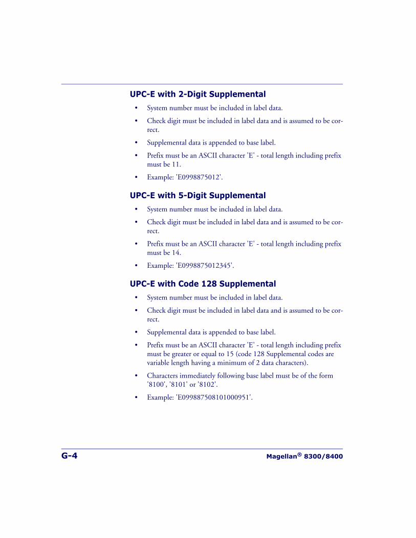
G-4 Magellan® 8300/8400
UPC-E with 2-Digit Supplemental
• System number must be included in label data.
• Check digit must be included in label data and is assumed to be cor-rect.
• Supplemental data is appended to base label.
• Prefix must be an ASCII character 'E' - total length including prefix must be 11.
• Example: 'E0998875012'.
UPC-E with 5-Digit Supplemental
• System number must be included in label data.
• Check digit must be included in label data and is assumed to be cor-rect.
• Prefix must be an ASCII character 'E' - total length including prefix must be 14.
• Example: 'E0998875012345'.
UPC-E with Code 128 Supplemental
• System number must be included in label data.
• Check digit must be included in label data and is assumed to be cor-rect.
• Supplemental data is appended to base label.
• Prefix must be an ASCII character 'E' - total length including prefix must be greater or equal to 15 (code 128 Supplemental codes are variable length having a minimum of 2 data characters).
• Characters immediately following base label must be of the form '8100', '8101' or '8102'.
• Example: 'E099887508101000951'.
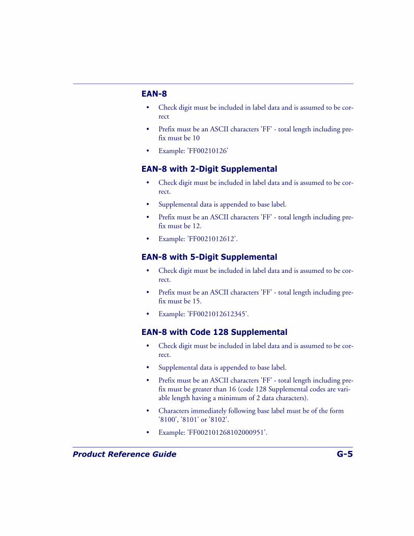
Product Reference Guide G-5
EAN-8
• Check digit must be included in label data and is assumed to be cor-rect
• Prefix must be an ASCII characters 'FF' - total length including pre-fix must be 10
• Example: 'FF00210126'
EAN-8 with 2-Digit Supplemental
• Check digit must be included in label data and is assumed to be cor-rect.
• Supplemental data is appended to base label.
• Prefix must be an ASCII characters 'FF' - total length including pre-fix must be 12.
• Example: 'FF0021012612'.
EAN-8 with 5-Digit Supplemental
• Check digit must be included in label data and is assumed to be cor-rect.
• Prefix must be an ASCII characters 'FF' - total length including pre-fix must be 15.
• Example: 'FF0021012612345'.
EAN-8 with Code 128 Supplemental
• Check digit must be included in label data and is assumed to be cor-rect.
• Supplemental data is appended to base label.
• Prefix must be an ASCII characters 'FF' - total length including pre-fix must be greater than 16 (code 128 Supplemental codes are vari-able length having a minimum of 2 data characters).
• Characters immediately following base label must be of the form '8100', '8101' or '8102'.
• Example: 'FF002101268102000951'.
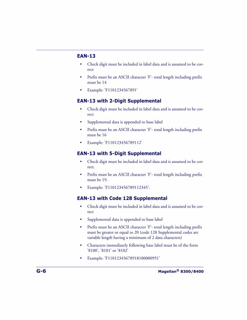
G-6 Magellan® 8300/8400
EAN-13
• Check digit must be included in label data and is assumed to be cor-rect
• Prefix must be an ASCII character 'F'- total length including prefix must be 14
• Example: 'F1101234567891'
EAN-13 with 2-Digit Supplemental
• Check digit must be included in label data and is assumed to be cor-rect
• Supplemental data is appended to base label
• Prefix must be an ASCII character 'F'- total length including prefix must be 16
• Example: 'F110123456789112'
EAN-13 with 5-Digit Supplemental
• Check digit must be included in label data and is assumed to be cor-rect.
• Prefix must be an ASCII character 'F'- total length including prefix must be 19.
• Example: 'F110123456789112345'.
EAN-13 with Code 128 Supplemental
• Check digit must be included in label data and is assumed to be cor-rect
• Supplemental data is appended to base label
• Prefix must be an ASCII character 'F'- total length including prefix must be greater or equal to 20 (code 128 Supplemental codes are variable length having a minimum of 2 data characters)
• Characters immediately following base label must be of the form '8100', '8101' or '8102'
• Example: 'F11012345678918100000951'
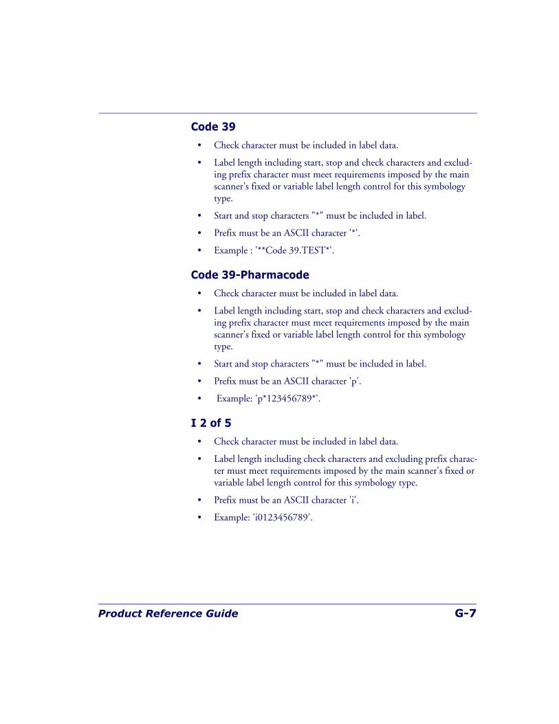
Product Reference Guide G-7
Code 39
• Check character must be included in label data.
• Label length including start, stop and check characters and exclud-ing prefix character must meet requirements imposed by the main scanner's fixed or variable label length control for this symbology type.
• Start and stop characters "*" must be included in label.
• Prefix must be an ASCII character '*'.
• Example : '**Code 39.TEST*'.
Code 39-Pharmacode
• Check character must be included in label data.
• Label length including start, stop and check characters and exclud-ing prefix character must meet requirements imposed by the main scanner's fixed or variable label length control for this symbology type.
• Start and stop characters "*" must be included in label.
• Prefix must be an ASCII character 'p'.
• Example: 'p*123456789*'.
I 2 of 5
• Check character must be included in label data.
• Label length including check characters and excluding prefix charac-ter must meet requirements imposed by the main scanner's fixed or variable label length control for this symbology type.
• Prefix must be an ASCII character 'i'.
• Example: 'i0123456789'.
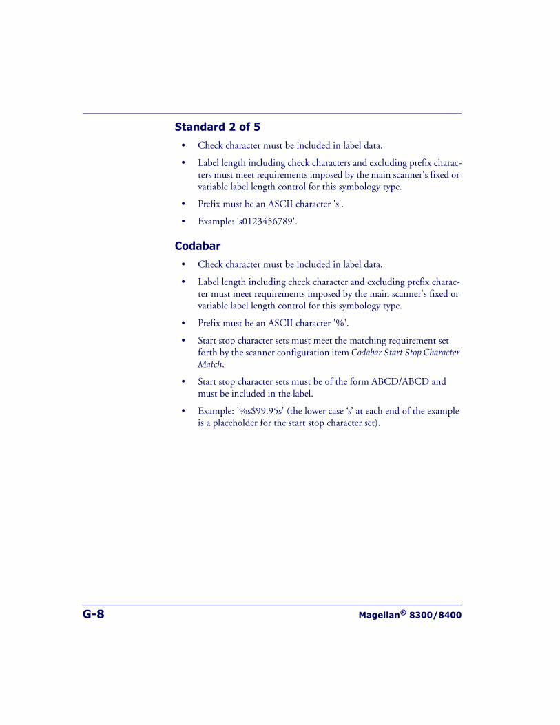
G-8 Magellan® 8300/8400
Standard 2 of 5
• Check character must be included in label data.
• Label length including check characters and excluding prefix charac-ters must meet requirements imposed by the main scanner's fixed or variable label length control for this symbology type.
• Prefix must be an ASCII character 's'.
• Example: 's0123456789'.
Codabar
• Check character must be included in label data.
• Label length including check character and excluding prefix charac-ter must meet requirements imposed by the main scanner's fixed or variable label length control for this symbology type.
• Prefix must be an ASCII character '%'.
• Start stop character sets must meet the matching requirement set forth by the scanner configuration item Codabar Start Stop Character Match.
• Start stop character sets must be of the form ABCD/ABCD and must be included in the label.
• Example: '%s$99.95s' (the lower case ‘s’ at each end of the example is a placeholder for the start stop character set).
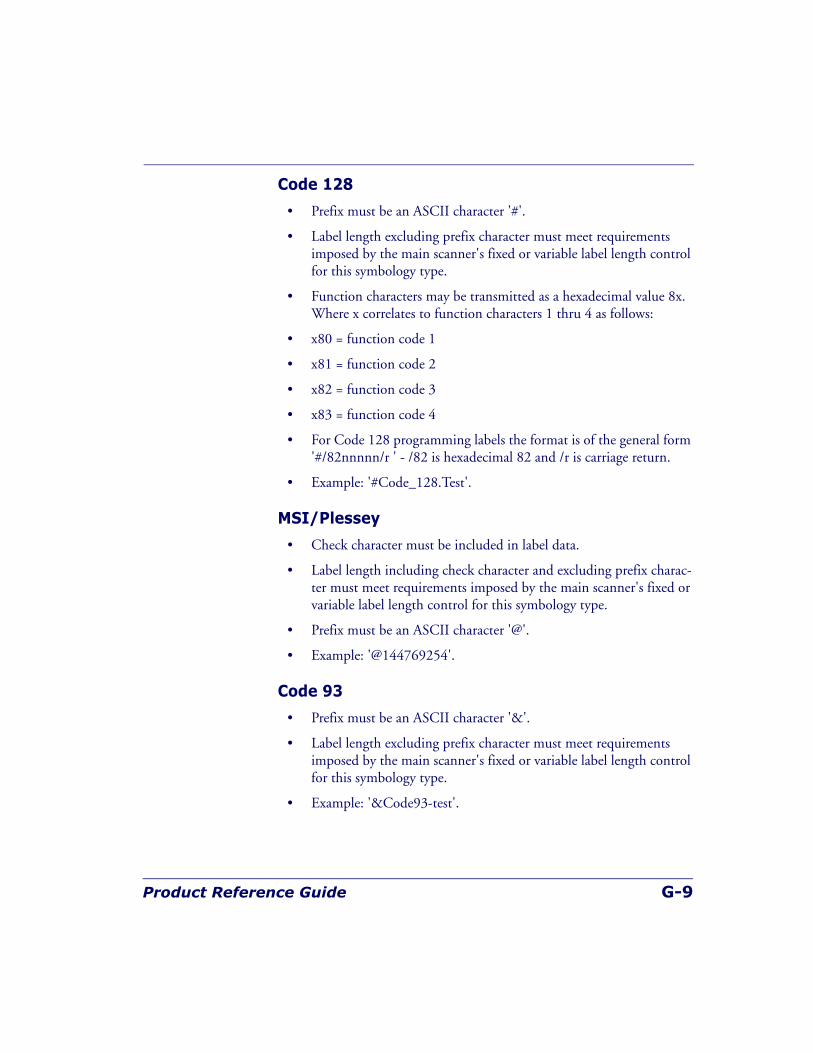
Product Reference Guide G-9
Code 128
• Prefix must be an ASCII character '#'.
• Label length excluding prefix character must meet requirements imposed by the main scanner's fixed or variable label length control for this symbology type.
• Function characters may be transmitted as a hexadecimal value 8x. Where x correlates to function characters 1 thru 4 as follows:
• x80 = function code 1
• x81 = function code 2
• x82 = function code 3
• x83 = function code 4
• For Code 128 programming labels the format is of the general form '#/82nnnnn/r ' - /82 is hexadecimal 82 and /r is carriage return.
• Example: '#Code_128.Test'.
MSI/Plessey
• Check character must be included in label data.
• Label length including check character and excluding prefix charac-ter must meet requirements imposed by the main scanner's fixed or variable label length control for this symbology type.
• Prefix must be an ASCII character '@'.
• Example: '@144769254'.
Code 93
• Prefix must be an ASCII character '&'.
• Label length excluding prefix character must meet requirements imposed by the main scanner's fixed or variable label length control for this symbology type.
• Example: '&Code93-test'.
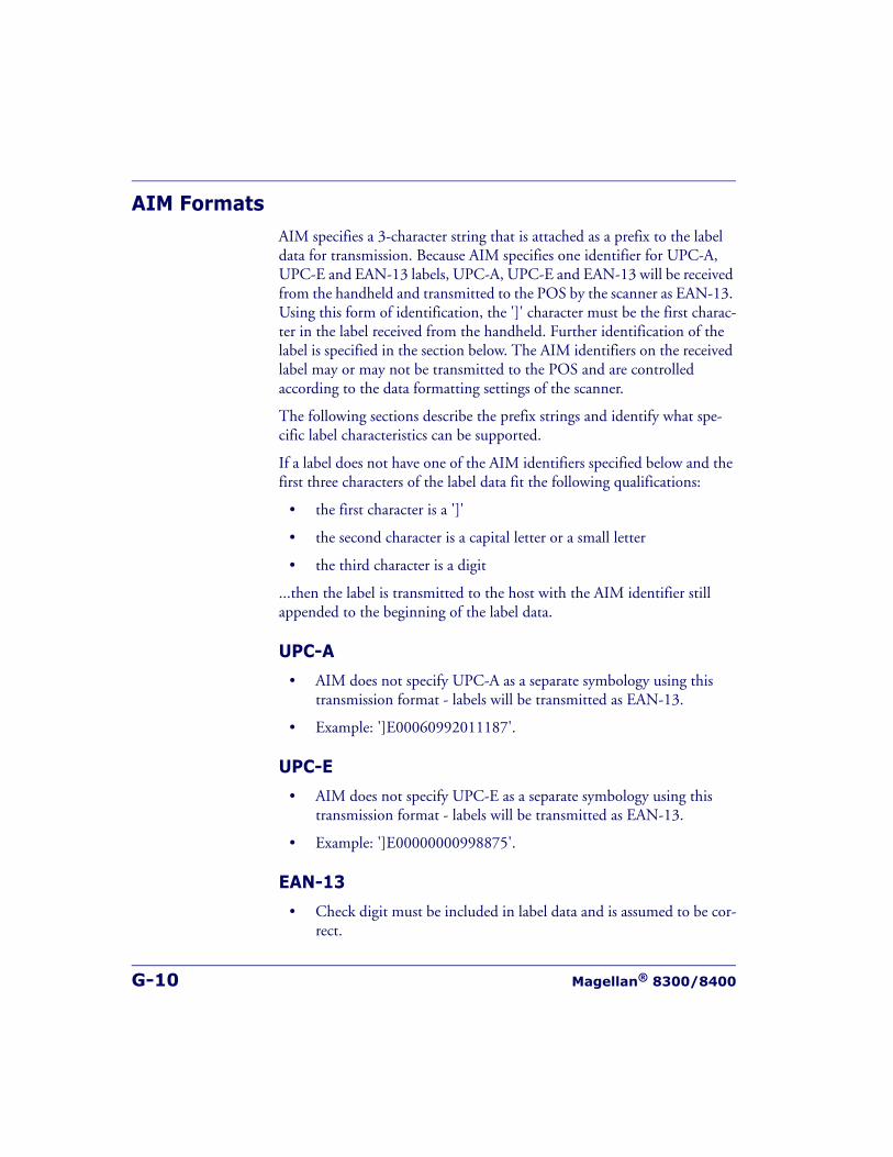
G-10 Magellan® 8300/8400
AIM FormatsAIM specifies a 3-character string that is attached as a prefix to the label data for transmission. Because AIM specifies one identifier for UPC-A, UPC-E and EAN-13 labels, UPC-A, UPC-E and EAN-13 will be received from the handheld and transmitted to the POS by the scanner as EAN-13. Using this form of identification, the ']' character must be the first charac-ter in the label received from the handheld. Further identification of the label is specified in the section below. The AIM identifiers on the received label may or may not be transmitted to the POS and are controlled according to the data formatting settings of the scanner.
The following sections describe the prefix strings and identify what spe-cific label characteristics can be supported.
If a label does not have one of the AIM identifiers specified below and the first three characters of the label data fit the following qualifications:
• the first character is a ']'
• the second character is a capital letter or a small letter
• the third character is a digit
...then the label is transmitted to the host with the AIM identifier still appended to the beginning of the label data.
UPC-A
• AIM does not specify UPC-A as a separate symbology using this transmission format - labels will be transmitted as EAN-13.
• Example: ']E00060992011187'.
UPC-E
• AIM does not specify UPC-E as a separate symbology using this transmission format - labels will be transmitted as EAN-13.
• Example: ']E00000000998875'.
EAN-13
• Check digit must be included in label data and is assumed to be cor-rect.
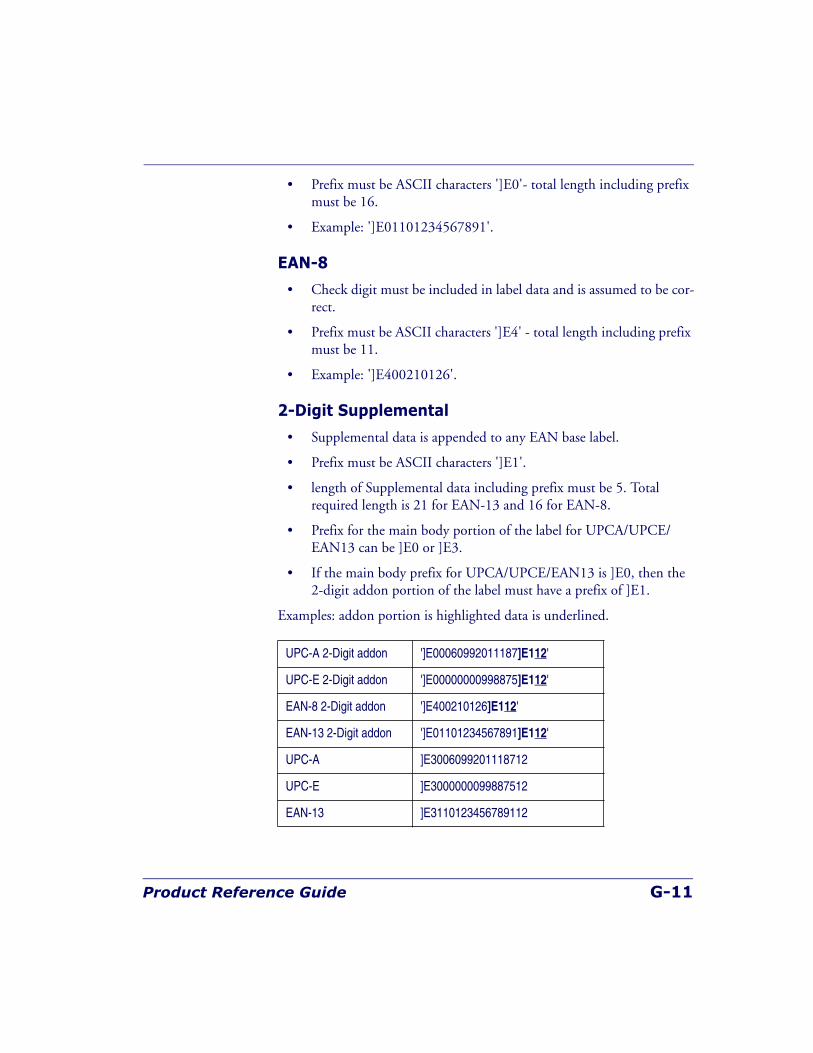
Product Reference Guide G-11
• Prefix must be ASCII characters ']E0'- total length including prefix must be 16.
• Example: ']E01101234567891'.
EAN-8
• Check digit must be included in label data and is assumed to be cor-rect.
• Prefix must be ASCII characters ']E4' - total length including prefix must be 11.
• Example: ']E400210126'.
2-Digit Supplemental
• Supplemental data is appended to any EAN base label.
• Prefix must be ASCII characters ']E1'.
• length of Supplemental data including prefix must be 5. Total required length is 21 for EAN-13 and 16 for EAN-8.
• Prefix for the main body portion of the label for UPCA/UPCE/EAN13 can be ]E0 or ]E3.
• If the main body prefix for UPCA/UPCE/EAN13 is ]E0, then the 2-digit addon portion of the label must have a prefix of ]E1.
Examples: addon portion is highlighted data is underlined.
UPC-A 2-Digit addon ']E00060992011187]E112'
UPC-E 2-Digit addon ']E00000000998875]E112'
EAN-8 2-Digit addon ']E400210126]E112'
EAN-13 2-Digit addon ']E01101234567891]E112'
UPC-A ]E3006099201118712
UPC-E ]E3000000099887512
EAN-13 ]E3110123456789112
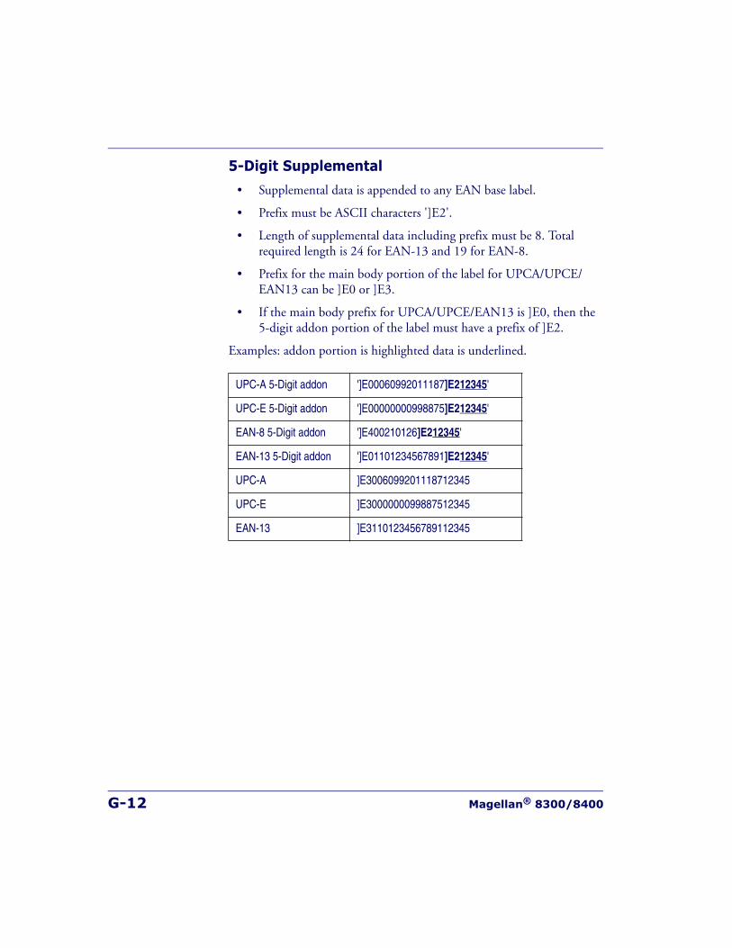
G-12 Magellan® 8300/8400
5-Digit Supplemental
• Supplemental data is appended to any EAN base label.
• Prefix must be ASCII characters ']E2'.
• Length of supplemental data including prefix must be 8. Total required length is 24 for EAN-13 and 19 for EAN-8.
• Prefix for the main body portion of the label for UPCA/UPCE/EAN13 can be ]E0 or ]E3.
• If the main body prefix for UPCA/UPCE/EAN13 is ]E0, then the 5-digit addon portion of the label must have a prefix of ]E2.
Examples: addon portion is highlighted data is underlined.
UPC-A 5-Digit addon ']E00060992011187]E212345'
UPC-E 5-Digit addon ']E00000000998875]E212345'
EAN-8 5-Digit addon ']E400210126]E212345'
EAN-13 5-Digit addon ']E01101234567891]E212345'
UPC-A ]E3006099201118712345
UPC-E ]E3000000099887512345
EAN-13 ]E3110123456789112345
Product Reference Guide G-13
Code 39
• Check character must be included in label data.
• Label length including start, stop and check characters and exclud-ing prefix characters must meet requirements imposed by the main scanner's fixed or variable label length control for this symbology type.
• Start and stop characters "*" must be included in label.
• Prefix must be ASCII characters ']A0' or ']A1'.
• Example: '*]A0Code 39.TEST*'.
Codabar
• Check character must be included in label data.
• Label length including check character and excluding prefix charac-ters must meet requirements imposed by the main scanner's fixed or variable label length control for this symbology type.
• Prefix must be ASCII characters ']F0'.
• Start stop character sets must meet the matching requirement set forth by the scanner configuration item Codabar Start Stop Character Match.
• Start stop character sets s must be of the form ABCD/ABCD and must be included in the label.
• Example: ']F0s$99.95s' (the lower case ‘s’ at each end of the example is a placeholder for the start stop character set).
MSI/Plessey
• Check character must be included in label data.
• Label length including check character and excluding prefix charac-ters must meet requirements imposed by the main scanner's fixed or variable label length control for this symbology type.
• Prefix must be ASCII characters ']M0'.
• Example: ']M0144769254'.
G-14 Magellan® 8300/8400
Code 93
• Prefix must be ASCII characters ']G0'.
• Label length excluding prefix characters must meet requirements imposed by the main scanner's fixed or variable label length control for this symbology type.
• Example : ']G0Code93-test'.
DataBar Omnidirectional
• Prefix must be ASCII characters ']e0'.
• Check character must be included in label.
• Label length excluding prefix characters must be 14 characters.
• Example: ']e001044123456789'.
DataBar Expanded
• Prefix must be ASCII characters ']e0'.
• Label length excluding prefix characters must be at least 1 character. Maximum length is the maximum label size supported by the scan-ner.
• Example: ']e001900123456789083103001750'.
I 2 of 5
• Check character must be included in label data.
• Label length including check characters and excluding prefix charac-ters must meet requirements imposed by the main scanner's fixed or variable label length control for this symbology type.
• Prefix must be ASCII characters ']I0', ']I1' or ']I2' (other prefixes specify different check character properties which are not sup-ported).
• Example: ']I10123456789'.
Product Reference Guide G-15
Standard 2 of 5
• Check character must be included in label data.
• Label length including check characters and excluding prefix charac-ters must meet requirements imposed by the main scanner's fixed or variable label length control for this symbology type.
• Prefix must be an ASCII character ']S0' (other prefixes specify dif-ferent check character properties which are not supported).
• Example: ']S00123456789'.
Code 128 / EAN128
• Prefix must be either ASCII characters ']C0', ']C1' or ']C2'.
• Label length excluding prefix character must meet requirements imposed by the main scanner's fixed or variable label length control for this symbology type.
• If EAN-128 Symbology is Enabled and prefix is ']C1', label will be identified as an EAN128 otherwise it is identified as a Code 128.
• A prefix of ']C0' designates that no function code is present in the 1st or 2nd character position.
• A prefix of ']C2' designates that a function code 1 is present in the 2nd character.
• Example : ']C0Code_128.Test'.

G-16 Magellan® 8300/8400
NOTES

Product Reference Guide G-17
NOTES

G-18 Magellan® 8300/8400
NOTES
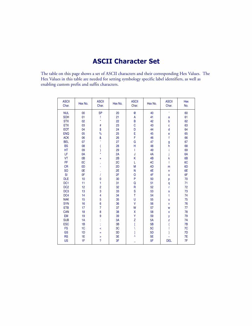
ASCII Character Set
The table on this page shows a set of ASCII characters and their corresponding Hex Values. The Hex Values in this table are needed for setting symbology specific label identifiers, as well as enabling custom prefix and suffix characters.
ASCIIChar.
Hex No.ASCIIChar.
Hex No.ASCIIChar.
Hex No.ASCIIChar.
HexNo.
NULSOHSTXETXEOTENQACKBELBSHTLFVTFFCRSOSI
DLEDC1DC2DC3DC4NAKSYNETBCANEM
SUBESCFSGSRSUS
000102030405060708090A0B0C0D0E0F101112131415161718191A1B1C1D1E1F
SP!“#$%&’()*+,-./0123456789:;<=>?
202122232425262728292A2B2C2D2E2F303132333435363738393A3B3C3D3E3F
@ABCDEFGHIJKLMNOPQRSTUVWXYZ[\]^_
404142434445464748494A4B4C4D4E4F505152535455565758595A5B5C5D5E5F
‘abcdefghijkl
mnopqrstuvwxyz{|}~
DEL
606162636465666768696A6B6C6D6E6F707172737475767778797A7B7C7D7E7F
AustraliaDatalogic Scanning Pty LtdTelephone: [61] (2) 9870 [email protected]
France and BeneluxDatalogic Scanning SarlTelephone: [33][email protected]
GermanyDatalogic Scanning GmbHTelephone: 49 (0) 61 51/93 [email protected]
IndiaDatalogic Scanning IndiaTelephone: 91- 22 - [email protected]
ItalyDatalogic Scanning SpATelephone: [39] (0) 39/[email protected]
JapanDatalogic Scanning KKTelephone: 81 (0)3 3491 [email protected]
Latin AmericaDatalogic Scanning, IncTelephone: (305) [email protected]
SingaporeDatalogic Scanning Singapore PTE LTDTelephone: (65) [email protected]
Spain and PortugalDatalogic Scanning Sarl Sucursal en EspañaTelephone: 34 91 746 28 [email protected]
United KingdomDatalogic Scanning LTDTelephone: 44 (0) 1923 [email protected]
Datalogic Scanning, Inc.959 Terry StreetEugene, OR 97402Telephone: (541) 683-5700Fax: (541) 345-7140
www.scanning.datalogic.com
©2006-2008 Datalogic Scanning, Inc. R44-2643 (Rev. H) 6/08
Recommended