GARRETT
GARRETT
Corporate Headquarters
Garrett Communications48531 Warm Springs Blvd.Fremont, CA 94539Phone 510.438.9071Fax 510.438.9072web: www.garrettcom.comemail: [email protected]
© Copyright 1998. Garrett Communications, Inc. All rights reserved.
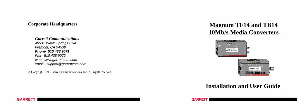
Magnum TF14 and TB14 10Mb/s Media Converters
Installation and User Guide
Po
l
GARRETT9VD
C .
3AM
P
Magnum TF14Media Converter
Lin
k
RX
TX
RX
Lin
k
Pw
r
RX
TWISTED PAIR FIBER
UP LINK
GARRETT
Magnum TB14Media Converter
Co
l
RX
Co
l
RX
Po
l
Lin
k
Pw
r
Jab
TWISTED PAIR COAX
UP LINK
INT
EXT
Magnum “14” 10Mb Media Converters Installation and User Guide (09/98)
GARRETT
Magnum TF14 and TB14 10Mb/s Media ConvertersInstallation and User Guide
Part #: 84-00121 (R09/98)
TrademarksMagnum is a trademark of Garrett Communications, Inc.UL is a registered trademark of Underwriters LaboratoriesEthernet is a trademark of Xerox CorporationVelcro is a trademark of Velcro U.S.A.
Important: Magnum Media Converters contain no user serviceable parts. Attemptedservice by unauthorized personnel shall render any and all warranties null and void. Ifproblems are experienced with a Magnum Media Converter, consult Section 5,Troubleshooting, of this User Guide.
1998 Garrett Communications, Inc.
Magnum “14” 10Mb Media Converters Installation and User Guide (09/98)
GARRETT
FCC STATEMENT
FEDERAL COMMUNICATIONS COMMISSION
RADIO FREQUENCY INTERFERENCE STATEMENTS
This equipment generates, uses, and can radiate radio frequency energy and if not installed and used
properly, that is, in strict accordance with the communication. It has been tested and found to comply
with the limits for a Class A computing device in accordance with the specifications in Subpart J of Part
15 of FCC rules, which are designed to provide reasonable protection against such interference when the
equipment is operated in a commercial environment. Operation of this equipment in a residential area is
likely to cause interference, in which case the user at his own expense will be required to take whatever
measures may be necessary to correct the interference.
Magnum “14” 10Mb Media Converters Installation and User Guide (09/98)
GARRETT
Please use the mailing address, email, phone and fax numbers listed below:
Garrett Communications, Inc.48531 Warm Springs Blvd.
Fremont, CA 94539
Phone (510) 438-9071Fax (510) 438-9072
email: [email protected]
web: www.garrettcom.com
Magnum “14” 10Mb Media Converters Installation and User Guide (09/98)
GARRETT
TABLE OF CONTENTS Page
1.0 SPECIFICATIONS............................................................................................. 11.1. Technical Specifications............................................................................ 1
2.0 INTRODUCTION .............................................................................................. 72.1 Inspecting the Package and the Product ...................................................... 72.2 Product Description ................................................................................... 82.3 Features and Benefits .............................................................................. 122.4 Applications for TF14 (fiber-series) and TB14 (BNC).............................. 142.5 Full-duplex twisted-pair to fiber applications ......................................... 172.6 Link Pass-through option, applications for the TF14-LP ........................... 17
3.0 INSTALLATION.............................................................................................. 203.1 Locating the Media Converter Unit......................................................... 203.2 TF14-series (fiber units) Power Supply............................................23
3.3 TB14 (BNC) Power Supply . . . . . . . .. . . . . . . . . . . . . … . . ......... …….233.4 Rack Mount Tray option for TF14’s and TB14’s .................................... 25
Magnum “14” 10Mb Media Converters Installation and User Guide (09/98)
GARRETT
3.5 Calculating Overall Segment Distances ………………………..27
3.6 Connecting Ethernet Media...................................................................... 303.6.1 Connecting Twisted Pair (RJ-45, standard and Link Pass-through) 30
3.6.2 Connecting Fiber ST, multi-mode & sgl.mode, full/half duplex....31
3.6.3 Connecting ThinNet 10BASE2 (BNC) ........................................ 334.0 OPERATION ................................................................................................... 33
4.1 Power Requirements, Power Supply Types for TF14’s vs. TB14’s............ 334.2 Front Panel LEDs - Magnum TF14, TF14s, TF14-LP (fiber)….. …......34
4.3 Front Panel LEDs - Magnum TB14 (BNC) ........................................... 354.4 BNC port, Internal Termination Switch…………………………………..354.5 Up-Link (Cross-over) Switch on RJ-45 port ............................................ 364.6 Full- and half-duplex transparent mode, fiber models ............................. 36
5.0 TROUBLESHOOTING.................................................................................... 37
Magnum “14” 10Mb Media Converters Installation and User Guide (09/98)
GARRETT
5.1 Before Calling for Assistance ................................................................... 375.2 When Calling for Assistance .................................................................... 395.3 Return Material Authorization (RMA) Procedure .................................... 405.4 Shipping and Packaging Information ........................................................ 42
Garrett Communications reserves the right to change specifications, performance characteristics and/ormodel offerings without notice.
Magnum “14” 10Mb Media Converters Installation and User Guide (09/98)
GARRETT
1
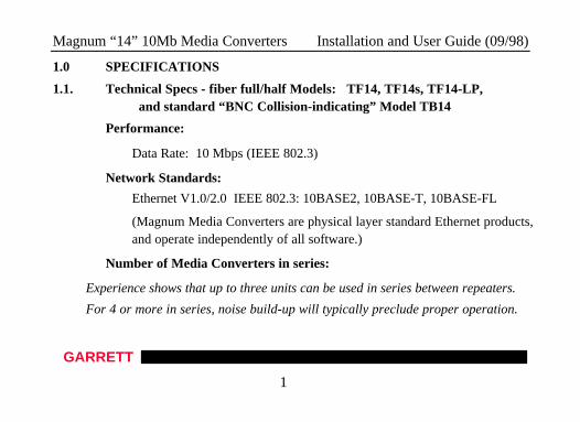
1.0 SPECIFICATIONS
1.1. Technical Specs - fiber full/half Models: TF14, TF14s, TF14-LP,and standard “BNC Collision-indicating” Model TB14
Performance:
Data Rate: 10 Mbps (IEEE 802.3)
Network Standards:
Ethernet V1.0/2.0 IEEE 802.3: 10BASE2, 10BASE-T, 10BASE-FL
(Magnum Media Converters are physical layer standard Ethernet products,and operate independently of all software.)
Number of Media Converters in series:
Experience shows that up to three units can be used in series between repeaters.
For 4 or more in series, noise build-up will typically preclude proper operation.
Magnum “14” 10Mb Media Converters Installation and User Guide (09/98)
GARRETT
2
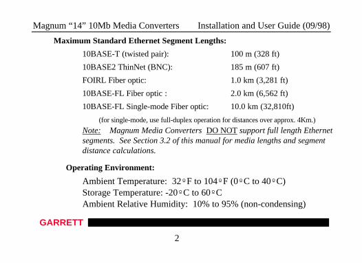
Maximum Standard Ethernet Segment Lengths:
10BASE-T (twisted pair): 100 m (328 ft)
10BASE2 ThinNet (BNC): 185 m (607 ft)
FOIRL Fiber optic: 1.0 km (3,281 ft)
10BASE-FL Fiber optic : 2.0 km (6,562 ft)
10BASE-FL Single-mode Fiber optic: 10.0 km (32,810ft)
(for single-mode, use full-duplex operation for distances over approx. 4Km.)
Note: Magnum Media Converters DO NOT support full length Ethernet segments. See Section 3.2 of this manual for media lengths and segment distance calculations.
Operating Environment:
Ambient Temperature: 32ºF to 104ºF (0ºC to 40ºC)Storage Temperature: -20ºC to 60ºCAmbient Relative Humidity: 10% to 95% (non-condensing)
Magnum “14” 10Mb Media Converters Installation and User Guide (09/98)
GARRETT
3
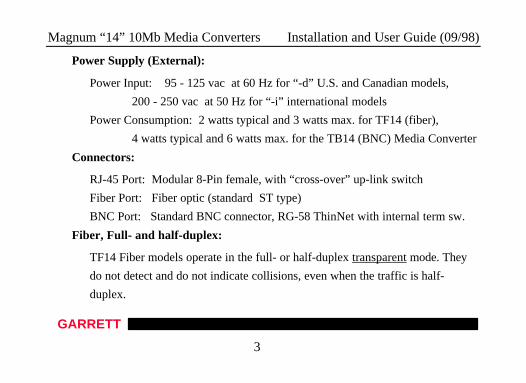
Power Supply (External):
Power Input: 95 - 125 vac at 60 Hz for “-d” U.S. and Canadian models,
200 - 250 vac at 50 Hz for “-i” international models
Power Consumption: 2 watts typical and 3 watts max. for TF14 (fiber),
4 watts typical and 6 watts max. for the TB14 (BNC) Media Converter
Connectors:
RJ-45 Port: Modular 8-Pin female, with “cross-over” up-link switch
Fiber Port: Fiber optic (standard ST type)
BNC Port: Standard BNC connector, RG-58 ThinNet with internal term sw.
Fiber, Full- and half-duplex:
TF14 Fiber models operate in the full- or half-duplex transparent mode. They
do not detect and do not indicate collisions, even when the traffic is half-
duplex.
Magnum “14” 10Mb Media Converters Installation and User Guide (09/98)
GARRETT
4
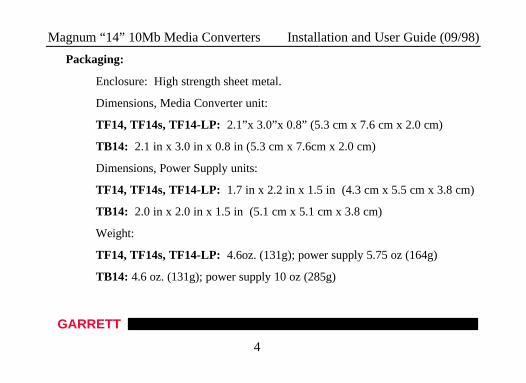
Packaging:
Enclosure: High strength sheet metal.
Dimensions, Media Converter unit:
TF14, TF14s, TF14-LP: 2.1”x 3.0”x 0.8” (5.3 cm x 7.6 cm x 2.0 cm)
TB14: 2.1 in x 3.0 in x 0.8 in (5.3 cm x 7.6cm x 2.0 cm)
Dimensions, Power Supply units:
TF14, TF14s, TF14-LP: 1.7 in x 2.2 in x 1.5 in (4.3 cm x 5.5 cm x 3.8 cm)
TB14: 2.0 in x 2.0 in x 1.5 in (5.1 cm x 5.1 cm x 3.8 cm)
Weight:
TF14, TF14s, TF14-LP: 4.6oz. (131g); power supply 5.75 oz (164g)
TB14: 4.6 oz. (131g); power supply 10 oz (285g)
Magnum “14” 10Mb Media Converters Installation and User Guide (09/98)
GARRETT
5
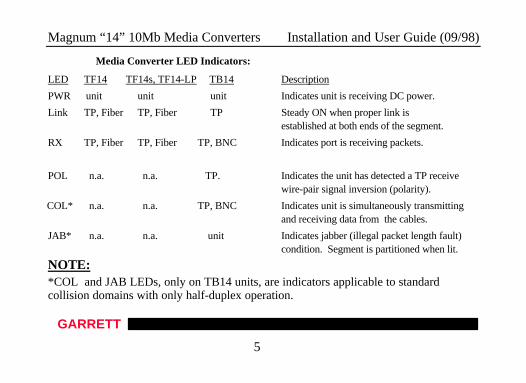
Media Converter LED Indicators:
LED TF14 TF14s, TF14-LP TB14 Description
PWR unit unit unit Indicates unit is receiving DC power.
Link TP, Fiber TP, Fiber TP Steady ON when proper link is established at both ends of the segment.
RX TP, Fiber TP, Fiber TP, BNC Indicates port is receiving packets.
POL n.a. n.a. TP. Indicates the unit has detected a TP receive wire-pair signal inversion (polarity).
COL* n.a. n.a. TP, BNC Indicates unit is simultaneously transmitting and receiving data from the cables.
JAB* n.a. n.a. unit Indicates jabber (illegal packet length fault) condition. Segment is partitioned when lit.
NOTE: *COL and JAB LEDs, only on TB14 units, are indicators applicable to standardcollision domains with only half-duplex operation.
Magnum “14” 10Mb Media Converters Installation and User Guide (09/98)
GARRETT
6
Agency Approvals:
115v 60 Hz Power Supply is UL Listed (UL 1950 and cUL) and CE.
230v 50 Hz Power Supply is same.
Emissions: Meets FCC Part 15 Class A, CE
Warranty: Three years, return to factory Made in USA
Magnum “14” 10Mb Media Converters Installation and User Guide (09/98)
GARRETT
7
2.0 INTRODUCTIONThis section describes the TF14, TF14s, TF14-LP, and TB14 including
appearance, features and typical applications.
2.1 Inspecting the Package and the ProductExamine the shipping container for obvious damage prior to installing this
product; notify the carrier of any damage which you believe occurred during shipment ordelivery. Inspect the contents of this package for any signs of damage and ensure thatthe items listed below are included.
This package should contain:
1 Magnum TF14 or TB14 Media Converter Unit
1 External Power Supply, either 115 vac 60 Hz or 230 vac 50 Hz
1 set Metal mounting clips and screws, 2 each
1 Velcro Tape section, approximately 3 inches in length
1 User Guide, i.e., this manual (continued next page)
Magnum “14” 10Mb Media Converters Installation and User Guide (09/98)
GARRETT
8
Remove the Magnum Media Converter from the shipping container. Be sureto keep the shipping container should you need to ship the unit at a later date.
In the event there are items missing or damaged contact your supplier. If youneed to return the unit use the original shipping container. Refer to Section 5,Troubleshooting, for specific return procedures.
2.2 Product Description
Magnum TF14 and TB14 10Mb Media Converters offer a compact, cost-effectiveway to adapt to non-RJ-45 Ethernet cabling as network requirements change and grow.The design provides units that are very small, power-efficient, but also full-function.
The “14” series offer a graceful way to convert and transmit data among twistedpair, fiber and thin coaxial network cabling environments. A variety of twisted-pair-to-fiber models provide for multi-mode or single-mode, transparent full- and half-duplexmode, and normal or Link Pass-through operation. Magnum TF14 and TB14 MediaConverters cost significantly less than full repeaters and can be used whenever mediadistance limitations will not be exceeded in the segment. All units are compatible withEthernet V 1.0 / 2.0 specifications and comply with IEEE 802.3 standards.
Magnum “14” 10Mb Media Converters Installation and User Guide (09/98)
GARRETT
9
Magnum TF14 and TB14 10Mb Media Converters are designed for quick andeasy installation even in very tight spaces. Media cables are easily attached to thecorresponding Media Converter. Because of their compact size, Magnum MediaConverters can be Velcro®-mounted on an office wall or the side of a desk or cabinet. Arack-mount tray that neatly holds the units and associated power supplies is available.
The standard “1-per-unit” external power supply plugs into a nearby AC wallsocket or power strip. Each converter features a full set of LEDs that convey essentialdiagnostic and status information. See Section 4.1, for LED function specifications.
Magnum Media Converters are designed to provide low-temperature operationover an extended period to make them some of the most reliable in the industry. Theirhigh-strength fabricated steel packaging shields against Radio Frequency Interference(RFI) and Electromagnetic Interference (EMI).
Magnum TF14 and TB14 10Mb Media Converters are specifically designed toconvert data signaling to allow transmission between two different Ethernet cablingtypes, allowing migration to a new media type while preserving segments of the pre-existing wiring structure. In addition, the TF14 allows fiber segments to be used withnew RJ-45 Ethernet hubs and switches that have insufficient (or none at all) fiber ports.
Magnum “14” 10Mb Media Converters Installation and User Guide (09/98)
GARRETT
10
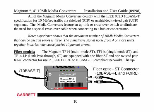
All of the Magnum Media Converters comply with the IEEE 802.3 10BASE-Tspecification for 10 Mb/sec traffic via shielded (STP) or unshielded twisted pair (UTP)segments. The Media Converters feature an up-link or cross-over switch to eliminatethe need for a special cross-over cable when connecting to a hub or concentrator.
Note: experience shows that the maximum number of 10Mb Media Convertersthat can be used in series is three. The cumulative signal noise from 4 or more unitstogether in series may cause packet alignment errors.
Fiber models: The Magnum TF14 (multi-mode ST), TF14s (single-mode ST), andTF14-LP (Link Pass-through, ST) are equipped with one fiber-ST and one twisted pairRJ-45 connector for use in IEEE FOIRL or 10BASE-FL compliant networks. The up-
GARRETT9VDC .3AMP
Magnum TF14Media Converter
LinkRX
TX
RX LinkPwr
RXTWISTED PAIR FIBER
UP LINK
(10BASE-T) Fiber optic - ST Connector(10BASE-FL and FOIRL)
Magnum “14” 10Mb Media Converters Installation and User Guide (09/98)
GARRETT
11
link (or crossover) switch on the RJ-45 port simplifies cable installation and connection.
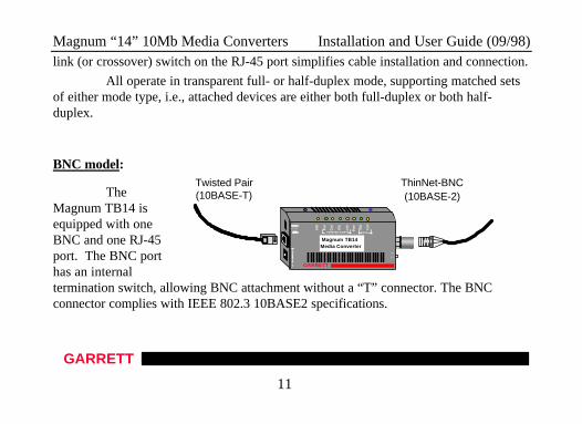
All operate in transparent full- or half-duplex mode, supporting matched setsof either mode type, i.e., attached devices are either both full-duplex or both half-duplex.
BNC model:
TheMagnum TB14 isequipped with oneBNC and one RJ-45port. The BNC porthas an internaltermination switch, allowing BNC attachment without a “T” connector. The BNCconnector complies with IEEE 802.3 10BASE2 specifications.
ThinNet-BNC(10BASE-2)
Twisted Pair(10BASE-T) P
ol
GARRETT
Magnum TB14Media Converter
Co
l
RX
Co
l
RX
Po
l
Lin
k
Pw
r
Jab
TWISTED PAIR COAX
UP LINK
INT
EXT
Magnum “14” 10Mb Media Converters Installation and User Guide (09/98)
GARRETT
12
2.3 Features and Benefits
nn Reduces Network Costs
Magnum Media Converters offer the ideal solution to quickly and
inexpensively connect Twisted Pair with Fiber or ThinNet media within
an expanding Ethernet network where full repeaters are not required.
nn No added Repeater Hop Count
Media Converters do not add signal timing delays associated with full
repeaters, and can be installed without increasing the repeater hop count
of an existing network.
nn Fiber / twisted-pair models for all fiber modes
A variety of twisted-pair-to-fiber models provide for multi-mode or
single-mode fiber, transparent full- or half-duplex mode, ST connectors,
and normal or Link Pass-through operation.
Magnum “14” 10Mb Media Converters Installation and User Guide (09/98)
GARRETT
13
nn Small, Compact, Rugged Design
Featuring a compact steel case with an external power supply, Magnum
TF14 and TB14 Media Converters can be conveniently installed in
minimal space in rack cabinets, on table-tops or wall-mounted.
nn Full Complement of LEDs.
Each model is equipped with a full complement of LEDs (7 for TF14, 11
for TB14) to provide network traffic status and basic diagnostic
information without additional network diagnostic equipment.
nn Highly Reliable and Dependable
Magnum Media Converters are based on a robust design and are
packaged in a metal enclosures to ensure high reliability and durability.
Magnum “14” 10Mb Media Converters Installation and User Guide (09/98)
GARRETT
14
2.4 Applications
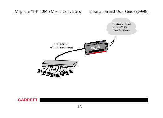
The primary function of a 10Mb Ethernet Media Converter is to permit twodifferent 10Mb media types to coexist inexpensively within the same network byallowing data to be transmitted and received between different media types.
Magnum Media Converters are typically used where new 10BASE-Tnetworking equipment is being installed and connected to new / existing fiber or BNCEthernet cabling. Alternatively, two twisted-pair-to-fiber models (typically TF14 formulti-mode and TF14s for single-mode) are convenient for inserting a fiber segment,either full- or half-duplex, into a twisted pair environment in order to connect to aremote workstation, hub or switch via fiber cabling, without increasing the repeater hopcount.
The TF14-LP, with the Link Pass-through feature, is often desired formanaged networks, where the LINK indication passes-through from the fiber side to theTP side. See Section 2.6 below for additional details.
Magnum Media Converters have an external power supply, enabling them tobe used to convert signals among media that does not have a power source as part of thecabling system, such as twisted pair, BNC and Fiber. (AUI ports can supply power).
Magnum “14” 10Mb Media Converters Installation and User Guide (09/98)
GARRETT
15
1 2 3 4 5 6 7 8 9 10 11 1213 14 15 16 17 18 19 20 21 22 23 24
10BASE-Twiring segment
Pwr
Central networkwith 10Mb/sfiber backbone
GARRETT
UP LINK
TX
RX
9VD
C .
3AM
P
Magnum TF14
Media Converter
Lin
k
RX
RX
Lin
k
Pw
r
TWISTED PAIRFIBER
Magnum “14” 10Mb Media Converters Installation and User Guide (09/98)
GARRETT
16
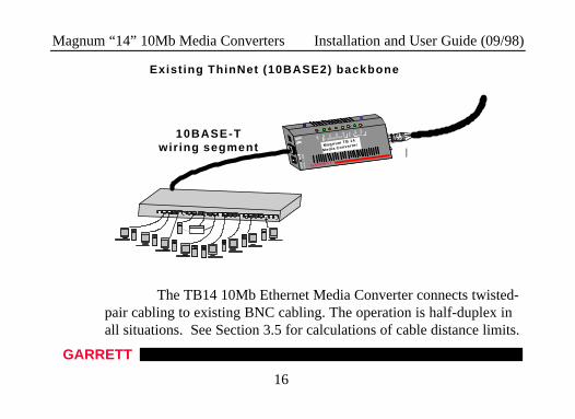
The TB14 10Mb Ethernet Media Converter connects twisted-pair cabling to existing BNC cabling. The operation is half-duplex inall situations. See Section 3.5 for calculations of cable distance limits.
Exist ing ThinNet (10BASE2) backbone
1 2 3 4 5 6 7 8 9 10 11 12 13 14 15 16 17 18 19 20 21 22 23 24
10BASE-Twiring segment
GARRETT
12 V
DC
1
AM
P
Magnum TB 14
Media Converter
Col
RX
Col R
X
Pol Li
nk Pw
r
Jab
TWISTED PAIRCOAX
Magnum “14” 10Mb Media Converters Installation and User Guide (09/98)
GARRETT
17
2.5 Full / half-duplex applications.Of the various 10Mb media types, only the twisted-pair to fiber combination is
capable of full-duplex (i.e., simultaneously transmitting and receiving on the same cablesegment) operation. Full-duplex is rarely required at 10Mb, but might occasionally bedesired to connect a 10Mb RJ-45 Switching Hub port over a fiber link to a full-duplexRJ-45 NIC in a remote server, or to connect one port of a full-duplex Switching Hub viafiber to another full-duplex 10Mb RJ-45 Switching Hub port.
All the TF14-series operate in transparent half-and full-duplex mode. Forhalf-duplex traffic, the TF14-series work correctly but do not detect or indicatecollisions.
2.6 Link Pass-through applications.
In managed networks, the LINK signal on a managed switch (or hub) port isused as an indicator that the attached cable segment is installed and operable. Thenetwork manager, using the SNMP agent, can troubleshoot the cabling by examining theLINK status on each port. This works fine as long as all of the cabling is twisted pair.
Magnum “14” 10Mb Media Converters Installation and User Guide (09/98)
GARRETT
18
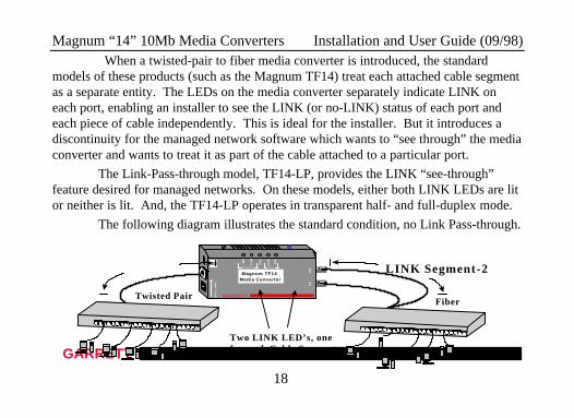
When a twisted-pair to fiber media converter is introduced, the standardmodels of these products (such as the Magnum TF14) treat each attached cable segmentas a separate entity. The LEDs on the media converter separately indicate LINK oneach port, enabling an installer to see the LINK (or no-LINK) status of each port andeach piece of cable independently. This is ideal for the installer. But it introduces adiscontinuity for the managed network software which wants to “see through” the mediaconverter and wants to treat it as part of the cable attached to a particular port.
The Link-Pass-through model, TF14-LP, provides the LINK “see-through”feature desired for managed networks. On these models, either both LINK LEDs are litor neither is lit. And, the TF14-LP operates in transparent half- and full-duplex mode.
The following diagram illustrates the standard condition, no Link Pass-through.
GARRETT9VD
C .
3AM
P
Magnum TF14Media Converter
Lin
k
RX
TX
RX
Lin
k
Pw
r
RX
T W I S T E D P A I R F I B E R
U P L I N K
1 2 3 4 5 6 7 8 9 1 0 1 1 1 2 1 3 1 4 1 5 1 6 1 7 1 8 1 9 2 0 2 1 2 2 2 3 2 4
1 2 3 4 5 6 7 8 9 1 0 1 1 1 2 1 3 1 4 1 5 1 6 1 7 1 8 1 9 2 0 2 1 2 2 2 3 2 4
FiberTwisted Pair
Two LINK LED’s, onefor each Cable Segment
LINK Segment-2
Magnum “14” 10Mb Media Converters Installation and User Guide (09/98)
GARRETT
19
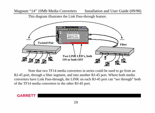
This diagram illustrates the Link Pass-through feature.
Note that two TF14 media converters in series could be used to go from anRJ-45 port, through a fiber segment, and into another RJ-45 port. Where both mediaconverters have Link Pass-through, the LINK on each RJ-45 port can “see through” bothof the TF14 media converters to the other RJ-45 port.
Po
l
1 2 3 4 5 6 7 8 9 10 11 12 13 14 15 16 17 18 19 20 21 22 23 24
1 2 3 4 5 6 7 8 9 10 11 12 13 14 15 16 17 18 19 20 21 22 23 24
FiberTwisted Pair
Two LINK LED’s, bothON or both OFF
GARRETT9VD
C .
3AM
P
Magnum TF14Media Converter
Lin
k
RX
TX
RX
Lin
k
Pw
r
RX
TWISTED PAIR FIBER
UP LINK
Magnum “14” 10Mb Media Converters Installation and User Guide (09/98)
GARRETT
20
3.0 INSTALLATION
This section describes the installation of the Magnum TF14 and TB14 MediaConverters, including location, segment distance calculation and media connection.
3.1 Locating the Media Converter Unit
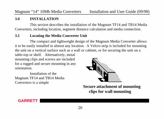
The compact and lightweight design of the Magnum Media Converter allowsit to be easily installed in almost any location. A Velcro strip is included for mountingthe unit on a vertical surface such as a wall or cabinet, or for securing the unit on atable-top or shelf. Alternatively, metalmounting clips and screws are includedfor a rugged and secure mounting in anyorientation.
Installation of theMagnum TF14 and TB14 MediaConverters is a simple
Secure attachment of mountingclips for wall mounting
Magnum “14” 10Mb Media Converters Installation and User Guide (09/98)
GARRETT
21
Locating the Media Converter Unit (continued)
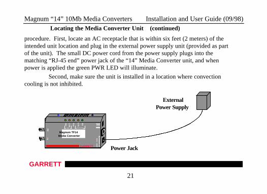
procedure. First, locate an AC receptacle that is within six feet (2 meters) of theintended unit location and plug in the external power supply unit (provided as partof the unit). The small DC power cord from the power supply plugs into thematching “RJ-45 end” power jack of the “14” Media Converter unit, and whenpower is applied the green PWR LED will illuminate.
Second, make sure the unit is installed in a location where convectioncooling is not inhibited.
Po
lGARRETT
9VD
C .3A
MP
Magnum TF14Media Converter
Lin
k
RX
TX
RX
Lin
k
Pw
r
RX
TWISTED PAIRFIBER
UP LINK
ExternalPower Supply
Power Jack
Magnum “14” 10Mb Media Converters Installation and User Guide (09/98)
GARRETT
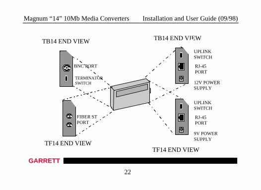
22
TB14 END VIEW
BNC PORT
TERMINATORSWITCH
UPLINKSWITCH
RJ-45PORT
9V POWERSUPPLY
FIBER STPORT
TF14 END VIEW
TB14 END VIEW
UPLINKSWITCH
RJ-45PORT
12V POWERSUPPLY
TF14 END VIEW
Magnum “14” 10Mb Media Converters Installation and User Guide (09/98)
GARRETT
23
3.2 TF14-series (fiber units) Power Supply
The TF14-series external power supply unit supplied is one of two types; oneversion for AC input power of 115 vac 60 Hz, and one version for 230 vac 50 Hz.Examine the power supply to make sure the version you have is the right type for yourAC power system. The 115 vac version has a small transformer integral with aconvenience power outlet plug, and a lightweight DC power cord to the applicablepower jack on the hub. The 230 vac version has a small transformer integral with anIEC-type power plug for a user-supplied AC power cord with a convenience poweroutlet plug. It also includes a lightweight DC power cord to the power jack on theTF14. unit. Both power supply models supply 9 volt (at 2 watts typical) of DC power tothe TF14 Media Converter.
3.3 TB14 (BNC units) Power Supply
The TB14 external power supply unit supplied is one of two types; oneversion for AC input power of 115 vac 60 Hz, and one version for 230 vac 50 Hz.Examine the power supply to make sure the version you have is the right type for yourAC power system. The 115 vac version has a small transformer integral with aconvenience power outlet plug, and a lightweight DC power cord to the applicable
Magnum “14” 10Mb Media Converters Installation and User Guide (09/98)
GARRETT
24
power jack on the media converter. The 230 vac version has a small transformer integralwith an IEC-type power plug for a user-supplied AC power cord with a conveniencepower outlet plug. It also includes a lightweight DC power cord to the power jack onthe TF14. unit. Both power supply models supply 12 volt (at 4 watts typical) of DCpower to the TB14 Media Converter.
Magnum “14” 10Mb Media Converters Installation and User Guide (09/98)
GARRETT
25
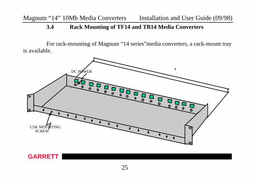
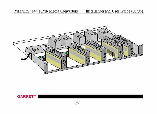
3.4 Rack Mounting of TF14 and TB14 Media Converters
For rack-mounting of Magnum “14 series”media converters, a rack-mount trayis available.
CSK MOUNTINGSCREW
DC POWER
Magnum “14” 10Mb Media Converters Installation and User Guide (09/98)
GARRETT
26
Magnum “14” 10Mb Media Converters Installation and User Guide (09/98)
GARRETT
27
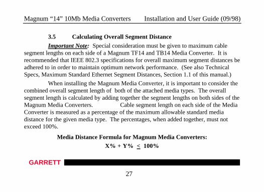
3.5 Calculating Overall Segment Distance
Important Note: Special consideration must be given to maximum cablesegment lengths on each side of a Magnum TF14 and TB14 Media Converter. It isrecommended that IEEE 802.3 specifications for overall maximum segment distances beadhered to in order to maintain optimum network performance. (See also TechnicalSpecs, Maximum Standard Ethernet Segment Distances, Section 1.1 of this manual.)
When installing the Magnum Media Converter, it is important to consider thecombined overall segment length of both of the attached media types. The overallsegment length is calculated by adding together the segment lengths on both sides of theMagnum Media Converters. Cable segment length on each side of the MediaConverter is measured as a percentage of the maximum allowable standard mediadistance for the given media type. The percentages, when added together, must notexceed 100%.
Media Distance Formula for Magnum Media Converters:
X% + Y% < 100%
Magnum “14” 10Mb Media Converters Installation and User Guide (09/98)
GARRETT
28
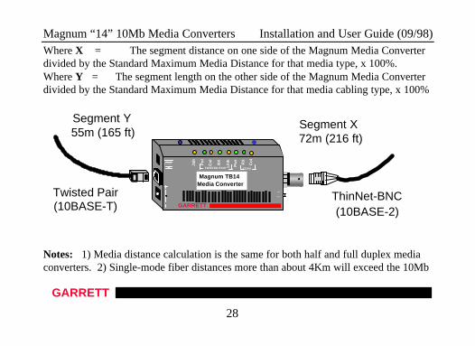
Where X = The segment distance on one side of the Magnum Media Converterdivided by the Standard Maximum Media Distance for that media type, x 100%.Where Y = The segment length on the other side of the Magnum Media Converterdivided by the Standard Maximum Media Distance for that media cabling type, x 100%
Notes: 1) Media distance calculation is the same for both half and full duplex mediaconverters. 2) Single-mode fiber distances more than about 4Km will exceed the 10Mb
Po
l
GARRETT
Magnum TB14Media Converter
Co
l
RX
Co
l
RX
Po
l
Lin
k
Pw
r
Jab
TWISTED PAIR COAX
UP LINK
INT
EXT
Segment Y55m (165 ft)
ThinNet-BNC(10BASE-2)
Twisted Pair(10BASE-T)
Segment X72m (216 ft)
Magnum “14” 10Mb Media Converters Installation and User Guide (09/98)
GARRETT
29
collision domain limits, and should be operated at either full-duplex or with light traffic.
Magnum “14” 10Mb Media Converters Installation and User Guide (09/98)
GARRETT
30
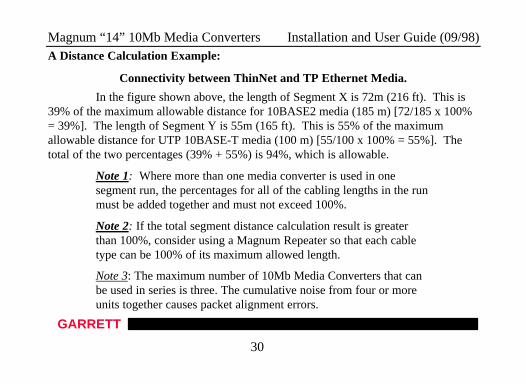
A Distance Calculation Example:
Connectivity between ThinNet and TP Ethernet Media.
In the figure shown above, the length of Segment X is 72m (216 ft). This is39% of the maximum allowable distance for 10BASE2 media (185 m) [72/185 x 100%= 39%]. The length of Segment Y is 55m (165 ft). This is 55% of the maximumallowable distance for UTP 10BASE-T media (100 m) [55/100 x 100% = 55%]. Thetotal of the two percentages (39% + 55%) is 94%, which is allowable.
Note 1: Where more than one media converter is used in onesegment run, the percentages for all of the cabling lengths in the runmust be added together and must not exceed 100%.
Note 2: If the total segment distance calculation result is greaterthan 100%, consider using a Magnum Repeater so that each cabletype can be 100% of its maximum allowed length.
Note 3: The maximum number of 10Mb Media Converters that canbe used in series is three. The cumulative noise from four or moreunits together causes packet alignment errors.
Magnum “14” 10Mb Media Converters Installation and User Guide (09/98)
GARRETT
31
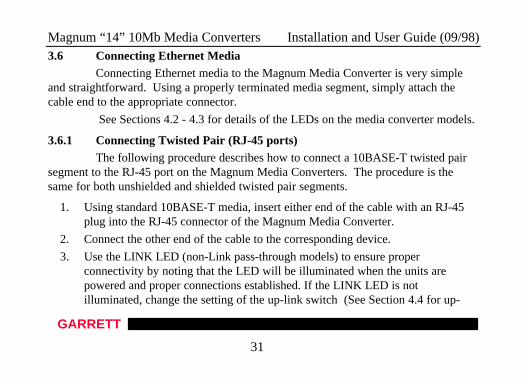
3.6 Connecting Ethernet MediaConnecting Ethernet media to the Magnum Media Converter is very simple
and straightforward. Using a properly terminated media segment, simply attach thecable end to the appropriate connector.
See Sections 4.2 - 4.3 for details of the LEDs on the media converter models.
3.6.1 Connecting Twisted Pair (RJ-45 ports)The following procedure describes how to connect a 10BASE-T twisted pair
segment to the RJ-45 port on the Magnum Media Converters. The procedure is thesame for both unshielded and shielded twisted pair segments.
1. Using standard 10BASE-T media, insert either end of the cable with an RJ-45 plug into the RJ-45 connector of the Magnum Media Converter.
2. Connect the other end of the cable to the corresponding device.
3. Use the LINK LED (non-Link pass-through models) to ensure properconnectivity by noting that the LED will be illuminated when the units arepowered and proper connections established. If the LINK LED is notilluminated, change the setting of the up-link switch (See Section 4.4 for up-
Magnum “14” 10Mb Media Converters Installation and User Guide (09/98)
GARRETT
32
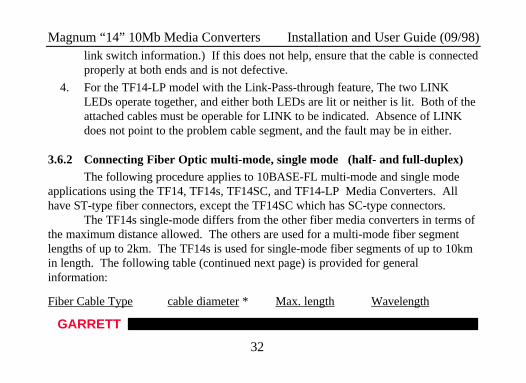
link switch information.) If this does not help, ensure that the cable is connectedproperly at both ends and is not defective.
4. For the TF14-LP model with the Link-Pass-through feature, The two LINKLEDs operate together, and either both LEDs are lit or neither is lit. Both of theattached cables must be operable for LINK to be indicated. Absence of LINKdoes not point to the problem cable segment, and the fault may be in either.
3.6.2 Connecting Fiber Optic multi-mode, single mode (half- and full-duplex)The following procedure applies to 10BASE-FL multi-mode and single mode
applications using the TF14, TF14s, TF14SC, and TF14-LP Media Converters. Allhave ST-type fiber connectors, except the TF14SC which has SC-type connectors.
The TF14s single-mode differs from the other fiber media converters in terms ofthe maximum distance allowed. The others are used for a multi-mode fiber segmentlengths of up to 2km. The TF14s is used for single-mode fiber segments of up to 10kmin length. The following table (continued next page) is provided for generalinformation:
Fiber Cable Type cable diameter * Max. length Wavelength
Magnum “14” 10Mb Media Converters Installation and User Guide (09/98)
GARRETT
33
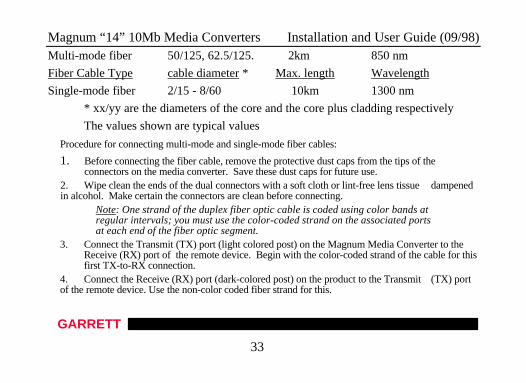
Multi-mode fiber 50/125, 62.5/125. 2km 850 nm
Fiber Cable Type cable diameter * Max. length Wavelength
Single-mode fiber 2/15 - 8/60 10km 1300 nm
* xx/yy are the diameters of the core and the core plus cladding respectively
The values shown are typical values
Procedure for connecting multi-mode and single-mode fiber cables:
1. Before connecting the fiber cable, remove the protective dust caps from the tips of theconnectors on the media converter. Save these dust caps for future use.
2. Wipe clean the ends of the dual connectors with a soft cloth or lint-free lens tissue dampenedin alcohol. Make certain the connectors are clean before connecting.
Note: One strand of the duplex fiber optic cable is coded using color bands atregular intervals; you must use the color-coded strand on the associated portsat each end of the fiber optic segment.
3. Connect the Transmit (TX) port (light colored post) on the Magnum Media Converter to theReceive (RX) port of the remote device. Begin with the color-coded strand of the cable for thisfirst TX-to-RX connection.
4. Connect the Receive (RX) port (dark-colored post) on the product to the Transmit (TX) portof the remote device. Use the non-color coded fiber strand for this.
Magnum “14” 10Mb Media Converters Installation and User Guide (09/98)
GARRETT
34
5. The LINK LED corresponding to the fiber port on the front of the product will illuminate (forstandard non-Link-Pass-through models) when a proper connection has been established at bothends (and when power is ON in the units at each end). If LINK is not lit after cable connection,the normal cause is improper cable polarity. Swap the fiber cables on the product connector toremedy this situation.
6. For the Link Pass-through model, connection is the same except that the LINK indication willnot be present unless LINK is made for the cables on both sides.
3.6.3 Connecting ThinNet 10BASE2Connect the ThinNet coax cable to the BNC connector on the TB14 Media
Converter in the same manner as is done for any standard BNC connection. Be surethat the BNC segment is properly terminated using a standard “T” connector andterminator.
4.0 OPERATIONThis section describes the operation of the Magnum TF14 and TB14 10Mb
Media Converters, including power supply requirements, up-link switch functionality,and a description of all LEDs.
4.1 Power Requirements, Power Supply Types for TF14 vs. TB14
Magnum “14” 10Mb Media Converters Installation and User Guide (09/98)
GARRETT
35
Magnum TF14 Media Converters are very power-efficient. They only requireabout 2 watts of power and are designed to be used with a tiny external 9-volt powersupply. This power supply is different from other power supplies used with anyother Magnum products, including even the companion TB14 unit.
Magnum TB14 Media Converters require 12v internal for the BNC port..They typically use about 5 watts of power and are designed to be used with an external12-volt power supply. This power supply is the same as the power supplies usedwith several other Magnum products, including 10Mb Magnum Personal Hubsand the TF14 and TB14 models of 10Mb Magnum Media Converters.
4.2 Front Panel LEDs - Magnum TF14, TF14s, and TF14-LP fiber-seriesLED DescriptionPWR Illuminates GREEN to indicate the unit is receiving DC power.LINK (per port) Illuminates to indicate proper connectivity on eachcable segment (non-Link Pass-through models). LINK will turn off in
the event connectivity is lost between the ends of each cable
Magnum “14” 10Mb Media Converters Installation and User Guide (09/98)
GARRETT
36
segment or a loss of power occurs in the unit or in the attached device. For Link Pass-through models, see Section 3.3.3 #6.
RX (per port) Illuminates GREEN to indicate data is being received.
4.3 Front Panel LEDs - - Magnum TB14
LED DescriptionPWR Illuminates GREEN to indicate the unit is receiving DC power.LINK (TP) Illuminates GREEN, to indicate proper connectivity on the10BASE-T network segment. LINK will turn off in the event connectivity islost between the ends of the twisted pair segment or a loss of power occurs inthe unit or remote device.RX (per port) Illuminates GREEN to indicate data is being received.POL (TP) Illuminates AMBER to indicate inverse polarity detected.
Magnum “14” 10Mb Media Converters Installation and User Guide (09/98)
GARRETT
37
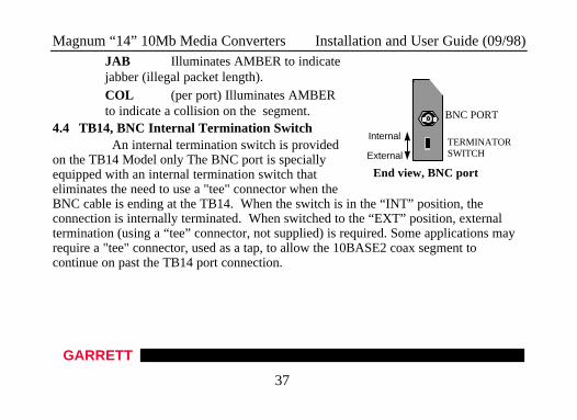
JAB Illuminates AMBER to indicatejabber (illegal packet length).COL (per port) Illuminates AMBERto indicate a collision on the segment.
4.4 TB14, BNC Internal Termination Switch An internal termination switch is providedon the TB14 Model only The BNC port is speciallyequipped with an internal termination switch thateliminates the need to use a "tee" connector when theBNC cable is ending at the TB14. When the switch is in the “INT” position, theconnection is internally terminated. When switched to the “EXT” position, externaltermination (using a “tee” connector, not supplied) is required. Some applications mayrequire a "tee" connector, used as a tap, to allow the 10BASE2 coax segment tocontinue on past the TB14 port connection.
End view, BNC port
Internal
External
BNC PORT
TERMINATORSWITCH
Magnum “14” 10Mb Media Converters Installation and User Guide (09/98)
GARRETT
38
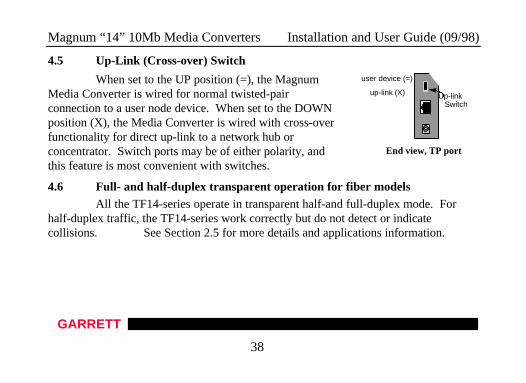
4.5 Up-Link (Cross-over) Switch
When set to the UP position (=), the MagnumMedia Converter is wired for normal twisted-pairconnection to a user node device. When set to the DOWNposition (X), the Media Converter is wired with cross-overfunctionality for direct up-link to a network hub orconcentrator. Switch ports may be of either polarity, andthis feature is most convenient with switches.
4.6 Full- and half-duplex transparent operation for fiber modelsAll the TF14-series operate in transparent half-and full-duplex mode. For
half-duplex traffic, the TF14-series work correctly but do not detect or indicatecollisions. See Section 2.5 for more details and applications information.
End view, TP port
Up-linkSwitch
up-link (X)
user device (=)
Magnum “14” 10Mb Media Converters Installation and User Guide (09/98)
GARRETT
39
5.0 TROUBLESHOOTINGAll Magnum Ethernet products are designed to provide reliability and
consistently high performance in all network environments. The installation ofMagnum TF14 and TB14 10Mb Media Converters is a simple procedure (see Section3.0, INSTALLATION); their operation is described in Section 4.0, OPERATION.
Should problems develop during installation or operation, this section shouldhelp to locate, identify and correct such problems. Please follow the suggestions listedbelow prior to contacting your supplier. However, if you are unsure of any proceduredescribed in this section, or if the Magnum Media Converter is not operating asexpected, do not attempt to repair or alter the unit. Contact your supplier (or ifunknown, contact Garrett Communications) for assistance.
5.1 Before Calling for Assistance
1. If difficulty is encountered when installing or operating the MagnumMedia Converter, refer back to Section 3.0, Installation and Section 4.0, Operation.Check to make sure that the various other components of the network are operable.
Magnum “14” 10Mb Media Converters Installation and User Guide (09/98)
GARRETT
40
2. Check the cables and connectors to ensure that they have been properlyconnected, and the cables/wires have not been crimped or in some way impaired duringinstallation. (About 90% of network downtime can be attributed to wiring andconnector problems.)
3. Make sure that the external DC power supply is properly attached to theunit, that it is of the proper type, and that it is plugged into a functioning electricaloutlet. Use the PWR LEDs to verify the unit is receiving proper power.
4. If the problem is isolated to a network device other than the MagnumMedia Converter, it is recommended that the problem device be replaced with a knowngood device. Verify whether or not the problem is corrected. If not, go to Step 5 below.If the problem is corrected, the Magnum Media Converter and its associated cables arefunctioning properly.
5. If the problem continues after completing Step 4 above, contact yoursupplier of the Magnum Media Converter (or if unknown, contact GarrettCommunications) by fax, phone or email for assistance.
Magnum “14” 10Mb Media Converters Installation and User Guide (09/98)
GARRETT
41
5.2 When Calling for Assistance
Please be prepared to provide the following information.
1. A complete description of the problem, including the following points:a. The nature and duration of the problem;b. Situations when the problem occurs;c. The components involved in the problem;d. Any particular application that, when used, appears to create the problem;
2. An accurate list of Garrett Communications product model(s) involved, with serial number(s). Include the date(s) that you purchased the products fromyour supplier.
3. It is useful to include other network equipment models and related hardware, including personal computers, workstations, terminals and printers; plus, the various network media types being used.
4. A record of changes that have been made to your network configuration prior to the occurrence of the problem. Any changes to system administration
procedures should all be noted in this record.
Magnum “14” 10Mb Media Converters Installation and User Guide (09/98)
GARRETT
42
5.3 Return Material Authorization (RMA) Procedure
All returns for repair must be accompanied by a Return Material
Authorization (RMA) number. To obtain an RMA number, contact Garrett
Communications Customer Support at (510) 438-9071 (office hours: 8AM - 5PM
Pacific Standard Time) or send email to [email protected]. Please have the
following information available when calling:
Name and phone number of your contact person.Name of your company / institutionYour shipping addressProduct nameSerial Number (or Invoice Number)Packing List Number (or Sales Order Number)Date of installationFailure symptoms, including a full description of the problem.
Magnum “14” 10Mb Media Converters Installation and User Guide (09/98)
GARRETT
43
Garrett Communications will carefully test and evaluate all returned products,will repair products that are under warranty at no charge, and will return thewarranty-repaired units to the sender with shipping charges prepaid (see WarrantyInformation, Appendix A, for complete details). However, if the problem orcondition causing the return cannot be duplicated by Garrett Communications, theunit will be returned as:
No Problem Found.
Garrett Communications, Inc. reserves the right to charge for the testing of
non-defective units under warranty. Testing and repair of product that is not under
warranty will result in a customer (user) charge.
Magnum “14” 10Mb Media Converters Installation and User Guide (09/98)
GARRETT
44
5.4 Shipping and Packaging Information
Should you need to ship the unit back to Garrett Communications, pleasefollow these instructions:
1. Package the unit carefully. It is recommended that you use the originalcontainer if available. Units should be wrapped in a "bubble-wrap" plasticsheet or bag for shipping protection. ( You may retain all connectors and thisInstallation Guide.)
CAUTION : Do not pack the unit in Styrofoam "popcorn" type packingmaterial. This material may cause electro-static shock damage to the unit.
2. Clearly mark the Return Material Authorization (RMA) number on theoutside of the shipping container.
3. Garrett Communications is not responsible for your return shipping charges.4. Ship the package to:
Garrett Communications48531 Warm Springs Blvd.Fremont, CA 94539
Attn.: Customer Service
Recommended