GA-G41M-ComboLGA775 socket motherboard for Intel® Core™ processor family/Intel® Pentium® processor family/Intel® Celeron® processor family
User's ManualRev. 130212ME-G41MC-1302R

Motherboard
GA
-G41M
-Com
bo
May 24, 2010
May 24, 2010
MotherboardGA-G41M-Combo
Copyright© 2010 GIGA-BYTE TECHNOLOGY CO., LTD. All rights reserved.The trademarks mentioned in this manual are legally registered to their respective owners.
DisclaimerInformation in this manual is protected by copyright laws and is the property of GIGABYTE. Changes to the specifications and features in this manual may be made by GIGABYTE with-out prior notice. No part of this manual may be reproduced, copied, translated, transmitted, or published in any form or by any means without GIGABYTE's prior written permission.
Documentation ClassificationsIn order to assist in the use of this product, GIGABYTE provides the following types of documentations: For detailed product information, carefully read the User's Manual. For instructions on how to use GIGABYTE's unique features, read or download the information on/from the Support&Downloads\Motherboard\Technology Guide page on our website.
For product-related information, check on our website at: http://www.gigabyte.com
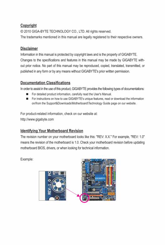
Identifying Your Motherboard RevisionThe revision number on your motherboard looks like this: "REV: X.X." For example, "REV: 1.0" means the revision of the motherboard is 1.0. Check your motherboard revision before updating motherboard BIOS, drivers, or when looking for technical information.
Example:
- 4 -
Table of Contents
GA-G41M-Combo Motherboard Layout ..........................................................................5
Chapter 1 Hardware Installation .....................................................................................61-1 Installation Precautions .................................................................................... 61-2 Product Specifications ...................................................................................... 71-3 Installing the CPU and CPU Cooler ................................................................. 9
1-3-1 Installing the CPU .....................................................................................................9
1-4 Installing the Memory ..................................................................................... 101-4-1 Dual Channel Memory Configuration .....................................................................10
1-5 Installing an Expansion Card ......................................................................... 101-6 Back Panel Connectors .................................................................................. 111-7 Internal Connectors ........................................................................................ 12
Chapter 2 BIOS Setup ..................................................................................................212-1 Startup Screen ............................................................................................... 212-2 The Main Menu .............................................................................................. 212-3 MB Intelligent Tweaker(M.I.T.) ........................................................................ 222-4 Standard CMOS Features .............................................................................. 282-5 Advanced BIOS Features .............................................................................. 292-6 Advanced Chipset Features ........................................................................... 312-7 Integrated Peripherals .................................................................................... 322-8 Power Management Setup ............................................................................. 342-9 PnP/PCI Configurations ................................................................................. 362-10 PC Health Status ............................................................................................ 362-11 Load Fail-Safe Defaults .................................................................................. 372-12 Load Optimized Defaults ................................................................................ 382-13 Set Supervisor/User Password ...................................................................... 382-14 Save & Exit Setup .......................................................................................... 392-15 Exit Without Saving ........................................................................................ 39
Chapter 3 Drivers Installation ........................................................................................403-1 Installing Chipset Drivers ............................................................................... 40
Regulatory Statements ..................................................................................................41
- 5 -
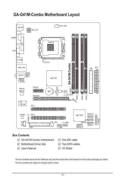
GA-G41M-Combo Motherboard Layout
KB_MS
COMA
CPU_FAN
LGA775
GA-G
41M-
Com
bo
CD_IN
F_AUDIO
AUDIO
B_BIOS
M_BIOS
IDE
SPDI
F_O
DDR3
_1
DDR3
_2
BAT
ATX_12V
Intel® G41
Intel® ICH7
FDD
PCIEX16
VGA
USB_LAN
CLR_
CMOS
CODEC
SYS_FAN
COMB
F_USB1
F_USB2
F_PA
NEL
SATA2_0SATA2_1
SATA2_2
SATA2_3
Atheros AR8151
R_USB
PCI2
PCI1
PCIEX1
LPT
iTEIT8718F
ATXDD
R2_1
DDR2
_2
Box Contents GA-G41M-Combo motherboard One IDE cable Motherboard driver disk Two SATA cables User's Manual I/O Shield
The box contents above are for reference only and the actual items shall depend on the product package you obtain. The box contents are subject to change without notice.

Hardware Installation - 6 -
1-1 Installation PrecautionsThe motherboard contains numerous delicate electronic circuits and components which can become damaged as a result of electrostatic discharge (ESD). Prior to installation, carefully read the user's manual and follow these procedures: • Prior to installation, do not remove or break motherboard S/N (Serial Number) sticker or
warranty sticker provided by your dealer. These stickers are required for warranty validation. • Always remove the AC power by unplugging the power cord from the power outlet before
installing or removing the motherboard or other hardware components. • When connecting hardware components to the internal connectors on the motherboard,
make sure they are connected tightly and securely. • When handling the motherboard, avoid touching any metal leads or connectors. • It is best to wear an electrostatic discharge (ESD) wrist strap when handling electronic com-
ponents such as a motherboard, CPU or memory. If you do not have an ESD wrist strap, keep your hands dry and first touch a metal object to eliminate static electricity.
• Prior to installing the motherboard, please have it on top of an antistatic pad or within an electrostatic shielding container.
• Before unplugging the power supply cable from the motherboard, make sure the power sup-ply has been turned off.
• Before turning on the power, make sure the power supply voltage has been set according to the local voltage standard.
• Before using the product, please verify that all cables and power connectors of your hard-ware components are connected.
• To prevent damage to the motherboard, do not allow screws to come in contact with the motherboard circuit or its components.
• Make sure there are no leftover screws or metal components placed on the motherboard or within the computer casing.
• Do not place the computer system on an uneven surface. • Do not place the computer system in a high-temperature environment. • Turning on the computer power during the installation process can lead to damage to sys-
tem components as well as physical harm to the user. • If you are uncertain about any installation steps or have a problem related to the use of the
product, please consult a certified computer technician.
Chapter 1 Hardware Installation
- 7 - Hardware Installation
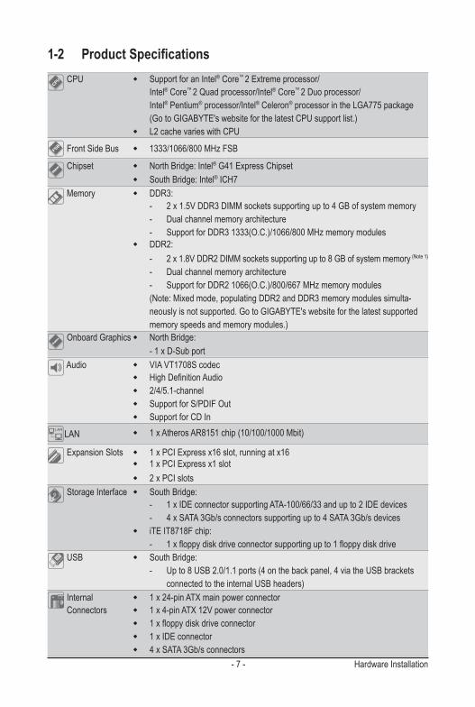
1-2 Product Specifications CPU w Support for an Intel® Core™ 2 Extreme processor/
Intel® Core™ 2 Quad processor/Intel® Core™ 2 Duo processor/ Intel® Pentium® processor/Intel® Celeron® processor in the LGA775 package (Go to GIGABYTE's website for the latest CPU support list.) w L2 cache varies with CPU
Front Side Bus w 1333/1066/800 MHz FSB
Chipset w North Bridge: Intel® G41 Express Chipset w South Bridge: Intel® ICH7
Memory w DDR3: - 2 x 1.5V DDR3 DIMM sockets supporting up to 4 GB of system memory - Dual channel memory architecture - Support for DDR3 1333(O.C.)/1066/800 MHz memory modules w DDR2: - 2 x 1.8V DDR2 DIMM sockets supporting up to 8 GB of system memory (Note 1)
- Dual channel memory architecture - Support for DDR2 1066(O.C.)/800/667 MHz memory modules (Note: Mixed mode, populating DDR2 and DDR3 memory modules simulta- neously is not supported. Go to GIGABYTE's website for the latest supported memory speeds and memory modules.)
Onboard Graphics w North Bridge: - 1 x D-Sub port
Audio w VIA VT1708S codec w High Definition Audio w 2/4/5.1-channel w Support for S/PDIF Out w Support for CD In
LAN w 1 x Atheros AR8151 chip (10/100/1000 Mbit)
Expansion Slots w 1 x PCI Express x16 slot, running at x16 w 1 x PCI Express x1 slot w 2 x PCI slots
Storage Interface w South Bridge: - 1 x IDE connector supporting ATA-100/66/33 and up to 2 IDE devices - 4 x SATA 3Gb/s connectors supporting up to 4 SATA 3Gb/s devices w iTE IT8718F chip: - 1 x floppy disk drive connector supporting up to 1 floppy disk drive
USB w South Bridge: - Up to 8 USB 2.0/1.1 ports (4 on the back panel, 4 via the USB brackets connected to the internal USB headers)
Internal w 1 x 24-pin ATX main power connector Connectors w 1 x 4-pin ATX 12V power connector w 1 x floppy disk drive connector w 1 x IDE connector w 4 x SATA 3Gb/s connectors
Hardware Installation - 8 -
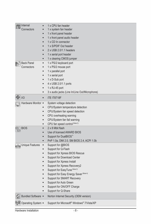
Internal w 1 x CPU fan header Connectors w 1 x system fan header w 1 x front panel header w 1 x front panel audio header w 1 x CD In connector w 1 x S/PDIF Out header w 2 x USB 2.0/1.1 headers w 1 x serial port header w 1 x clearing CMOS jumper
Back Panel w 1 x PS/2 keyboard port Connectors w 1 x PS/2 mouse port w 1 x parallel port w 1 x serial port w 1 x D-Sub port w 4 x USB 2.0/1.1 ports w 1 x RJ-45 port w 3 x audio jacks (Line In/Line Out/Microphone)
I/O w iTE IT8718F
Hardware Monitor w System voltage detection w CPU/System temperature detection w CPU/System fan speed detection w CPU overheating warning w CPU/System fan fail warning w CPU fan speed control (Note 2)
BIOS w 2 x 8 Mbit flash w Use of licensed AWARD BIOS w Support for DualBIOS™
w PnP 1.0a, DMI 2.0, SM BIOS 2.4, ACPI 1.0b Unique Features w Support for @BIOS
w Support for Q-Flash w Support for Xpress BIOS Rescue w Support for Download Center w Support for Xpress Install w Support for Xpress Recovery2 w Support for EasyTune (Note 3)
w Support for Easy Energy Saver (Note 4)
w Support for SMART Recovery w Support for Auto Green w Support for ON/OFF Charge w Support for Q-Share
Bundled Software w Norton Internet Security (OEM version)
Operating System w Support for Microsoft® Windows® 7/Vista/XP
- 9 - Hardware Installation
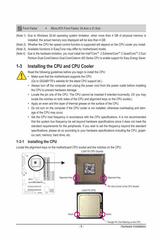
(Note 1) Due to Windows 32-bit operating system limitation, when more than 4 GB of physical memory is installed, the actual memory size displayed will be less than 4 GB.
(Note 2) Whether the CPU fan speed control function is supported will depend on the CPU cooler you install.(Note 3) Available functions in EasyTune may differ by motherboard model.(Note 4) Due to the hardware limitation, you must install the Intel®CoreTM 2 Extreme/CoreTM 2 Quad/CoreTM 2 Duo/
Pentium Dual-Core/Celeron Dual-Core/Celeron 400 Series CPU to enable support for Easy Energy Saver.
Form Factor w Micro ATX Form Factor; 24.4cm x 21.0cm
1-3 Installing the CPU and CPU CoolerRead the following guidelines before you begin to install the CPU:• Make sure that the motherboard supports the CPU. (Go to GIGABYTE's website for the latest CPU support list.)• Always turn off the computer and unplug the power cord from the power outlet before installing
the CPU to prevent hardware damage.• Locate the pin one of the CPU. The CPU cannot be inserted if oriented incorrectly. (Or you may
locate the notches on both sides of the CPU and alignment keys on the CPU socket.)• Apply an even and thin layer of thermal grease on the surface of the CPU.• Do not turn on the computer if the CPU cooler is not installed, otherwise overheating and dam-
age of the CPU may occur.• Set the CPU host frequency in accordance with the CPU specifications. It is not recommended
that the system bus frequency be set beyond hardware specifications since it does not meet the standard requirements for the peripherals. If you wish to set the frequency beyond the standard specifications, please do so according to your hardware specifications including the CPU, graph-ics card, memory, hard drive, etc.
1-3-1 Installing the CPULocate the alignment keys on the motherboard CPU socket and the notches on the CPU.
Notch Notch
Alignment KeyAlignment Key
LGA775 CPU
LGA775 CPU Socket
Pin One Corner of the CPU Socket
Triangle Pin One Marking on the CPU
Hardware Installation - 10 -
DDR3
_1
DDR3
_2
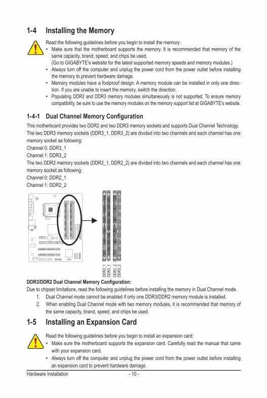
DDR3/DDR2 Dual Channel Memory Configuration:Due to chipset limitations, read the following guidelines before installing the memory in Dual Channel mode. 1. Dual Channel mode cannot be enabled if only one DDR3/DDR2 memory module is installed. 2. When enabling Dual Channel mode with two memory modules, it is recommended that memory of
the same capacity, brand, speed, and chips be used.
1-4 Installing the MemoryRead the following guidelines before you begin to install the memory:• Make sure that the motherboard supports the memory. It is recommended that memory of the
same capacity, brand, speed, and chips be used. (Go to GIGABYTE's website for the latest supported memory speeds and memory modules.)• Always turn off the computer and unplug the power cord from the power outlet before installing
the memory to prevent hardware damage.• Memory modules have a foolproof design. A memory module can be installed in only one direc-
tion. If you are unable to insert the memory, switch the direction.• Populating DDR2 and DDR3 memory modules simultaneously is not supported. To ensure memory
compatibility, be sure to use the memory modules on the memory support list at GIGABYTE's website.
1-4-1 Dual Channel Memory ConfigurationThis motherboard provides two DDR2 and two DDR3 memory sockets and supports Dual Channel Technology.The two DDR3 memory sockets (DDR3_1, DDR3_2) are divided into two channels and each channel has one memory socket as following: Channel 0: DDR3_1 Channel 1: DDR3_2The two DDR2 memory sockets (DDR2_1, DDR2_2) are divided into two channels and each channel has one memory socket as following: Channel 0: DDR2_1 Channel 1: DDR2_2
DDR2
_1
DDR2
_2
1-5 Installing an Expansion CardRead the following guidelines before you begin to install an expansion card: • Make sure the motherboard supports the expansion card. Carefully read the manual that came
with your expansion card.• Always turn off the computer and unplug the power cord from the power outlet before installing
an expansion card to prevent hardware damage.
- 11 - Hardware Installation
1-6 Back Panel Connectors
• When removing the cable connected to a back panel connector, first remove the cable from your device and then remove it from the motherboard.
• When removing the cable, pull it straight out from the connector. Do not rock it side to side to prevent an electrical short inside the cable connector.
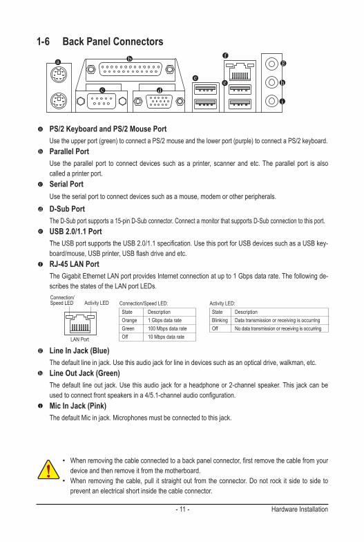
PS/2 Keyboard and PS/2 Mouse Port Use the upper port (green) to connect a PS/2 mouse and the lower port (purple) to connect a PS/2 keyboard.
Parallel Port Use the parallel port to connect devices such as a printer, scanner and etc. The parallel port is also
called a printer port. Serial Port
Use the serial port to connect devices such as a mouse, modem or other peripherals. D-Sub Port
The D-Sub port supports a 15-pin D-Sub connector. Connect a monitor that supports D-Sub connection to this port. USB 2.0/1.1 Port
The USB port supports the USB 2.0/1.1 specification. Use this port for USB devices such as a USB key-board/mouse, USB printer, USB flash drive and etc.
RJ-45 LAN Port The Gigabit Ethernet LAN port provides Internet connection at up to 1 Gbps data rate. The following de-
scribes the states of the LAN port LEDs.
Activity LED:State DescriptionBlinking Data transmission or receiving is occurringOff No data transmission or receiving is occurring
Connection/Speed LED:State DescriptionOrange 1 Gbps data rateGreen 100 Mbps data rateOff 10 Mbps data rate
Activity LEDConnection/Speed LED
LAN Port
Line In Jack (Blue) The default line in jack. Use this audio jack for line in devices such as an optical drive, walkman, etc.
Line Out Jack (Green) The default line out jack. Use this audio jack for a headphone or 2-channel speaker. This jack can be
used to connect front speakers in a 4/5.1-channel audio configuration. Mic In Jack (Pink)
The default Mic in jack. Microphones must be connected to this jack.
Hardware Installation - 12 -
1-7 Internal Connectors
Read the following guidelines before connecting external devices:• First make sure your devices are compliant with the connectors you wish to connect.• Before installing the devices, be sure to turn off the devices and your computer. Unplug the
power cord from the power outlet to prevent damage to the devices.• After installing the device and before turning on the computer, make sure the device cable has
been securely attached to the connector on the motherboard.
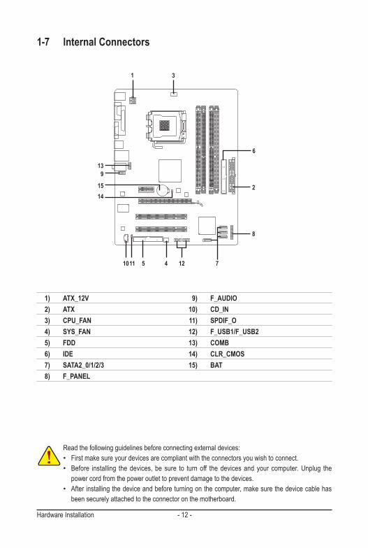
1) ATX_12V 2) ATX 3) CPU_FAN 4) SYS_FAN 5) FDD 6) IDE 7) SATA2_0/1/2/3 8) F_PANEL
9) F_AUDIO 10) CD_IN 11) SPDIF_O 12) F_USB1/F_USB2 13) COMB 14) CLR_CMOS 15) BAT
1
6
2
4
3
511
13
7
9
15
10
8
12
14
- 13 - Hardware Installation
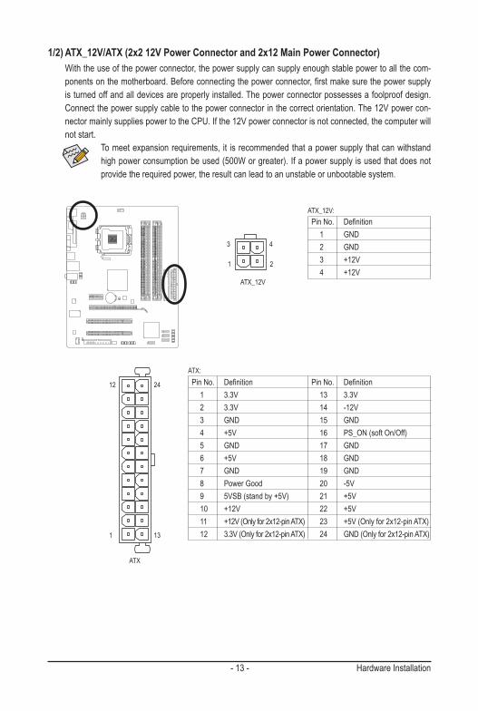
Pin No. Definition 1 GND 2 GND 3 +12V 4 +12V
ATX_12V:
DEBUG PORT
131
2412
ATX
ATX:Pin No. Definition 13 3.3V 14 -12V 15 GND 16 PS_ON (soft On/Off) 17 GND 18 GND 19 GND 20 -5V 21 +5V 22 +5V 23 +5V (Only for 2x12-pin ATX) 24 GND (Only for 2x12-pin ATX)
Pin No. Definition 1 3.3V 2 3.3V 3 GND 4 +5V 5 GND 6 +5V 7 GND 8 Power Good 9 5VSB (stand by +5V) 10 +12V 11 +12V (Only for 2x12-pin ATX) 12 3.3V (Only for 2x12-pin ATX)
1/2) ATX_12V/ATX (2x2 12V Power Connector and 2x12 Main Power Connector) With the use of the power connector, the power supply can supply enough stable power to all the com-
ponents on the motherboard. Before connecting the power connector, first make sure the power supply is turned off and all devices are properly installed. The power connector possesses a foolproof design. Connect the power supply cable to the power connector in the correct orientation. The 12V power con-nector mainly supplies power to the CPU. If the 12V power connector is not connected, the computer will not start.
To meet expansion requirements, it is recommended that a power supply that can withstand high power consumption be used (500W or greater). If a power supply is used that does not provide the required power, the result can lead to an unstable or unbootable system.
ATX_12V
1
3
2
4
Hardware Installation - 14 -
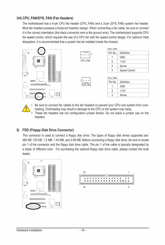
3/4) CPU_FAN/SYS_FAN (Fan Headers) The motherboard has a 4-pin CPU fan header (CPU_FAN) and a 3-pin (SYS_FAN) system fan header.
Most fan headers possess a foolproof insertion design. When connecting a fan cable, be sure to connect it in the correct orientation (the black connector wire is the ground wire). The motherboard supports CPU fan speed control, which requires the use of a CPU fan with fan speed control design. For optimum heat dissipation, it is recommended that a system fan be installed inside the chassis.
• Be sure to connect fan cables to the fan headers to prevent your CPU and system from over-heating. Overheating may result in damage to the CPU or the system may hang.
• These fan headers are not configuration jumper blocks. Do not place a jumper cap on the headers.
CPU_FAN:Pin No. Definition 1 GND 2 +12V 3 Sense 4 Speed Control
SYS_FAN:Pin No. Definition 1 GND 2 +12V 3 Sense
5) FDD (Floppy Disk Drive Connector) This connector is used to connect a floppy disk drive. The types of floppy disk drives supported are:
360 KB, 720 KB, 1.2 MB, 1.44 MB, and 2.88 MB. Before connecting a floppy disk drive, be sure to locate pin 1 of the connector and the floppy disk drive cable. The pin 1 of the cable is typically designated by a stripe of different color. For purchasing the optional floppy disk drive cable, please contact the local dealer.
1
2
33
34
CPU_FAN
DEBUG PORT
SYS_FAN
1
1
- 15 - Hardware Installation
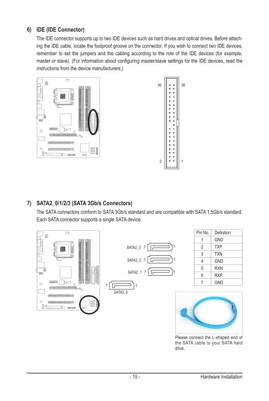
6) IDE (IDE Connector) The IDE connector supports up to two IDE devices such as hard drives and optical drives. Before attach-
ing the IDE cable, locate the foolproof groove on the connector. If you wish to connect two IDE devices, remember to set the jumpers and the cabling according to the role of the IDE devices (for example, master or slave). (For information about configuring master/slave settings for the IDE devices, read the instructions from the device manufacturers.)
7) SATA2_0/1/2/3 (SATA 3Gb/s Connectors) The SATA connectors conform to SATA 3Gb/s standard and are compatible with SATA 1.5Gb/s standard.
Each SATA connector supports a single SATA device.
Pin No. Definition 1 GND 2 TXP 3 TXN 4 GND 5 RXN 6 RXP 7 GND
12
3940
SATA2_0
SATA2_1
SATA2_2
SATA2_3
DEBUG PORT
DEBUG PORT
DEBUG PORT
7
7
7
1
1
1
7
DEBUG PORT
1
Please connect the L-shaped end of the SATA cable to your SATA hard drive.
Hardware Installation - 16 -
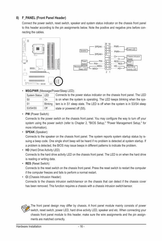
8) F_PANEL (Front Panel Header) Connect the power switch, reset switch, speaker and system status indicator on the chassis front panel
to this header according to the pin assignments below. Note the positive and negative pins before con-necting the cables.
The front panel design may differ by chassis. A front panel module mainly consists of power switch, reset switch, power LED, hard drive activity LED, speaker and etc. When connecting your chassis front panel module to this header, make sure the wire assignments and the pin assign-ments are matched correctly.
DEBU
G PO
RT
Power LED
12
1920
CI-CI+
PWR-
PWR+
MSG-
PW-
SPEAK+
SPEAK-
MSG+
PW+Message/Power/
Sleep LED
Speaker
Power Switch
HD-
RES+
HD+
RES-Hard Drive Activity LED
Reset Switch
Chassis Intrusion Header
• PW (Power Switch): Connects to the power switch on the chassis front panel. You may configure the way to turn off your
system using the power switch (refer to Chapter 2, "BIOS Setup," "Power Management Setup," for more information).
• SPEAK (Speaker): Connects to the speaker on the chassis front panel. The system reports system startup status by is-
suing a beep code. One single short beep will be heard if no problem is detected at system startup. If a problem is detected, the BIOS may issue beeps in different patterns to indicate the problem.
• HD (Hard Drive Activity LED) Connects to the hard drive activity LED on the chassis front panel. The LED is on when the hard drive
is reading or writing data.• RES (Reset Switch): Connects to the reset switch on the chassis front panel. Press the reset switch to restart the computer
if the computer freezes and fails to perform a normal restart.• CI (Chassis Intrusion Header): Connects to the chassis intrusion switch/sensor on the chassis that can detect if the chassis cover
has been removed. This function requires a chassis with a chassis intrusion switch/sensor.
• MSG/PWR (Message/Power/Sleep LED): Connects to the power status indicator on the chassis front panel. The LED
is on when the system is operating. The LED keeps blinking when the sys-tem is in S1 sleep state. The LED is off when the system is in S3/S4 sleep state or powered off (S5).
System Status LEDS0 OnS1 BlinkingS3/S4/S5 Off
- 17 - Hardware Installation
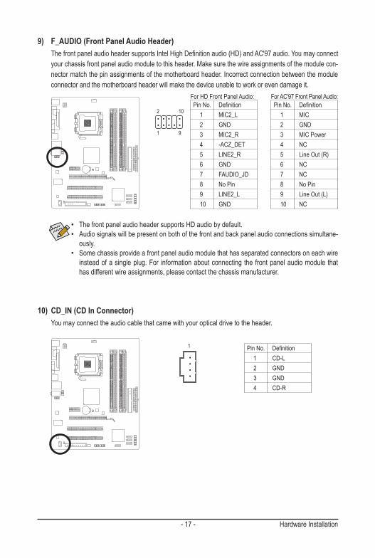
9) F_AUDIO (Front Panel Audio Header) The front panel audio header supports Intel High Definition audio (HD) and AC'97 audio. You may connect
your chassis front panel audio module to this header. Make sure the wire assignments of the module con-nector match the pin assignments of the motherboard header. Incorrect connection between the module connector and the motherboard header will make the device unable to work or even damage it.
Pin No. Definition 1 MIC2_L 2 GND 3 MIC2_R 4 -ACZ_DET 5 LINE2_R 6 GND 7 FAUDIO_JD 8 No Pin 9 LINE2_L 10 GND
Pin No. Definition 1 MIC 2 GND 3 MIC Power 4 NC 5 Line Out (R) 6 NC 7 NC 8 No Pin 9 Line Out (L) 10 NC
For HD Front Panel Audio: For AC'97 Front Panel Audio:
2 10
1 9
10) CD_IN (CD In Connector) You may connect the audio cable that came with your optical drive to the header.
Pin No. Definition 1 CD-L 2 GND 3 GND 4 CD-R
• The front panel audio header supports HD audio by default. • Audio signals will be present on both of the front and back panel audio connections simultane-
ously. • Some chassis provide a front panel audio module that has separated connectors on each wire
instead of a single plug. For information about connecting the front panel audio module that has different wire assignments, please contact the chassis manufacturer.
1
Hardware Installation - 18 -
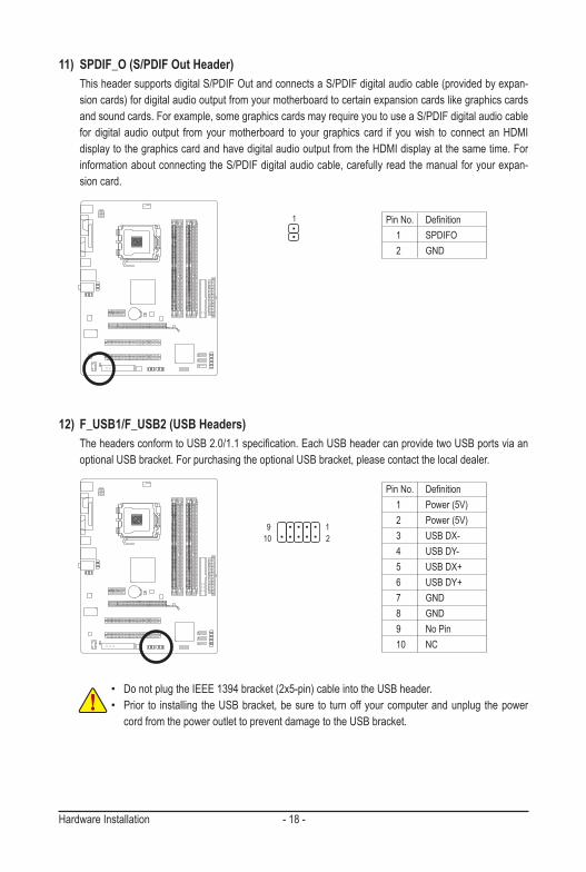
12) F_USB1/F_USB2 (USB Headers) The headers conform to USB 2.0/1.1 specification. Each USB header can provide two USB ports via an
optional USB bracket. For purchasing the optional USB bracket, please contact the local dealer.
Pin No. Definition 1 Power (5V) 2 Power (5V) 3 USB DX- 4 USB DY- 5 USB DX+ 6 USB DY+ 7 GND 8 GND 9 No Pin 10 NC
• Do not plug the IEEE 1394 bracket (2x5-pin) cable into the USB header.• Prior to installing the USB bracket, be sure to turn off your computer and unplug the power
cord from the power outlet to prevent damage to the USB bracket.
109
21
11) SPDIF_O (S/PDIF Out Header) This header supports digital S/PDIF Out and connects a S/PDIF digital audio cable (provided by expan-
sion cards) for digital audio output from your motherboard to certain expansion cards like graphics cards and sound cards. For example, some graphics cards may require you to use a S/PDIF digital audio cable for digital audio output from your motherboard to your graphics card if you wish to connect an HDMI display to the graphics card and have digital audio output from the HDMI display at the same time. For information about connecting the S/PDIF digital audio cable, carefully read the manual for your expan-sion card.
Pin No. Definition 1 SPDIFO 2 GND
1
- 19 - Hardware Installation
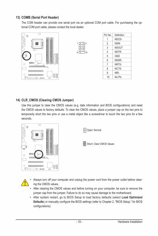
13) COMB (Serial Port Header) The COM header can provide one serial port via an optional COM port cable. For purchasing the op-
tional COM port cable, please contact the local dealer.
Pin No. Definition 1 NDCD- 2 NSIN 3 NSOUT 4 NDTR- 5 GND 6 NDSR- 7 NRTS- 8 NCTS- 9 NRI- 10 No Pin
14) CLR_CMOS (Clearing CMOS Jumper) Use this jumper to clear the CMOS values (e.g. date information and BIOS configurations) and reset
the CMOS values to factory defaults. To clear the CMOS values, place a jumper cap on the two pins to temporarily short the two pins or use a metal object like a screwdriver to touch the two pins for a few seconds.
Open: Normal
Short: Clear CMOS Values
• Always turn off your computer and unplug the power cord from the power outlet before clear-ing the CMOS values.
• After clearing the CMOS values and before turning on your computer, be sure to remove the jumper cap from the jumper. Failure to do so may cause damage to the motherboard.
• After system restart, go to BIOS Setup to load factory defaults (select Load Optimized Defaults) or manually configure the BIOS settings (refer to Chapter 2, "BIOS Setup," for BIOS configurations).
109
21
Hardware Installation - 20 -
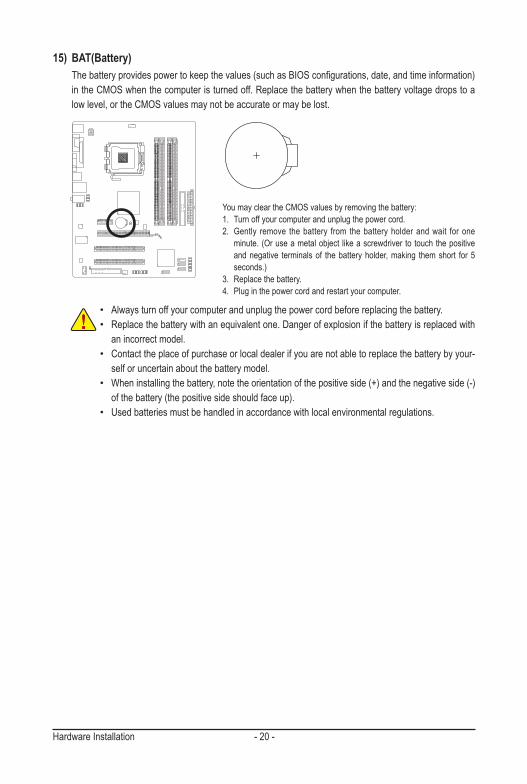
15) BAT(Battery) The battery provides power to keep the values (such as BIOS configurations, date, and time information)
in the CMOS when the computer is turned off. Replace the battery when the battery voltage drops to a low level, or the CMOS values may not be accurate or may be lost.
You may clear the CMOS values by removing the battery:1. Turn off your computer and unplug the power cord.2. Gently remove the battery from the battery holder and wait for one
minute. (Or use a metal object like a screwdriver to touch the positive and negative terminals of the battery holder, making them short for 5 seconds.)
3. Replace the battery.4. Plug in the power cord and restart your computer.
• Always turn off your computer and unplug the power cord before replacing the battery.• Replace the battery with an equivalent one. Danger of explosion if the battery is replaced with
an incorrect model. • Contact the place of purchase or local dealer if you are not able to replace the battery by your-
self or uncertain about the battery model.• When installing the battery, note the orientation of the positive side (+) and the negative side (-)
of the battery (the positive side should face up).• Used batteries must be handled in accordance with local environmental regulations.
- 21 - BIOS Setup
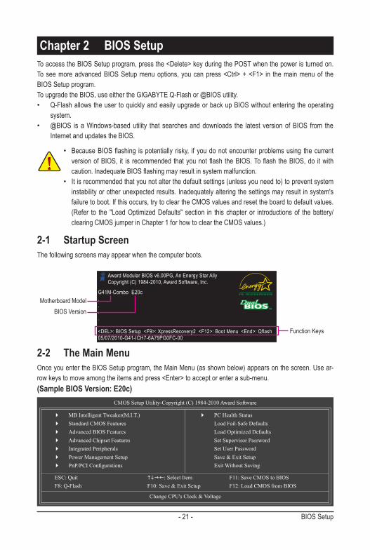
To access the BIOS Setup program, press the <Delete> key during the POST when the power is turned on. To see more advanced BIOS Setup menu options, you can press <Ctrl> + <F1> in the main menu of the BIOS Setup program.To upgrade the BIOS, use either the GIGABYTE Q-Flash or @BIOS utility. • Q-Flash allows the user to quickly and easily upgrade or back up BIOS without entering the operating
system.• @BIOS is a Windows-based utility that searches and downloads the latest version of BIOS from the
Internet and updates the BIOS.
Chapter 2 BIOS Setup
• Because BIOS flashing is potentially risky, if you do not encounter problems using the current version of BIOS, it is recommended that you not flash the BIOS. To flash the BIOS, do it with caution. Inadequate BIOS flashing may result in system malfunction.
• It is recommended that you not alter the default settings (unless you need to) to prevent system instability or other unexpected results. Inadequately altering the settings may result in system's failure to boot. If this occurs, try to clear the CMOS values and reset the board to default values. (Refer to the "Load Optimized Defaults" section in this chapter or introductions of the battery/clearing CMOS jumper in Chapter 1 for how to clear the CMOS values.)
2-1 Startup ScreenThe following screens may appear when the computer boots.
Motherboard Model BIOS Version
Award Modular BIOS v6.00PG, An Energy Star Ally Copyright (C) 1984-2010, Award Software, Inc.
G41M-Combo E20c....
<DEL>: BIOS Setup <F9>: XpressRecovery2 <F12>: Boot Menu <End>: Qflash05/07/2010-G41-ICH7-6A79PG0FC-00
Function Keys
2-2 The Main MenuOnce you enter the BIOS Setup program, the Main Menu (as shown below) appears on the screen. Use ar-row keys to move among the items and press <Enter> to accept or enter a sub-menu.(Sample BIOS Version: E20c)
CMOS Setup Utility-Copyright (C) 1984-2010 Award Software
Change CPU's Clock & Voltage
MB Intelligent Tweaker(M.I.T.) Standard CMOS Features Advanced BIOS Features Advanced Chipset Features Integrated Peripherals Power Management Setup PnP/PCIConfigurations
PC Health Status Load Fail-Safe Defaults Load Optimized Defaults Set Supervisor Password Set User Password Save & Exit Setup Exit Without Saving
ESC: Quit : Select Item F11: Save CMOS to BIOS F8: Q-Flash F10: Save & Exit Setup F12: Load CMOS from BIOS
BIOS Setup - 22 -
• If you do not find the settings you want in the Main Menu or a submenu, press <Ctrl>+<F1> to access more advanced options.
• When the system is not stable as usual, select the Load Optimized Defaults item to set your system to its defaults.
• The BIOS Setup menus described in this chapter are for reference only and may differ by BIOS version.
The Functions of the <F11> and <F12> keys (For the Main Menu Only) F11: Save CMOS to BIOS This function allows you to save the current BIOS settings to a profile. You can create up to 8 profiles
(Profile 1-8) and name each profile. First enter the profile name (to erase the default profile name, use the SPACE key) and then press <Enter> to complete.
F12: Load CMOS from BIOS If your system becomes unstable and you have loaded the BIOS default settings, you can use this
function to load the BIOS settings from a profile created before, without the hassles of reconfiguring the BIOS settings. First select the profile you wish to load, then press <Enter> to complete.
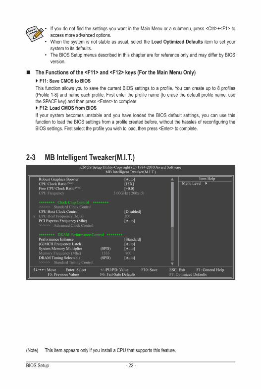
2-3 MB Intelligent Tweaker(M.I.T.)CMOS Setup Utility-Copyright (C) 1984-2010 Award Software
MB Intelligent Tweaker(M.I.T.)
Robust Graphics Booster [Auto] CPU Clock Ratio (Note) [15X] Fine CPU Clock Ratio (Note) [+0.0] CPU Frequency 3.00GHz ( 200x15)
******** Clock Chip Control ******** >>>>> Standard Clock Control CPU Host Clock Control [Disabled] x CPU Host Frequency (Mhz) 200 PCI Express Frequency (Mhz) [Auto] >>>>> Advanced Clock Control
******** DRAM Performance Control ******** Performance Enhance [Standard] (G)MCH Frequency Latch [Auto] System Memory Multiplier (SPD) [Auto] Memory Frequency (Mhz) 1333 800 DRAM Timing Selectable (SPD) [Auto] >>>>> Standard Timing Control
: Move Enter: Select +/-/PU/PD: Value F10: Save ESC: Exit F1: General Help F5: Previous Values F6: Fail-Safe Defaults F7: Optimized Defaults
Item HelpMenu Level
(Note) This item appears only if you install a CPU that supports this feature.
- 23 - BIOS Setup
(Note) This item appears only if you install a CPU that supports this feature.
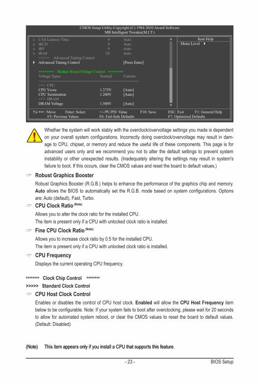
Whether the system will work stably with the overclock/overvoltage settings you made is dependent on your overall system configurations. Incorrectly doing overclock/overvoltage may result in dam-age to CPU, chipset, or memory and reduce the useful life of these components. This page is for advanced users only and we recommend you not to alter the default settings to prevent system instability or other unexpected results. (Inadequately altering the settings may result in system's failure to boot. If this occurs, clear the CMOS values and reset the board to default values.)
(Note) This item appears only if you install a CPU that supports this feature.
CMOS Setup Utility-Copyright (C) 1984-2010 Award SoftwareMB Intelligent Tweaker(M.I.T.)
: Move Enter: Select +/-/PU/PD: Value F10: Save ESC: Exit F1: General Help F5: Previous Values F6: Fail-Safe Defaults F7: Optimized Defaults
Item HelpMenu Level
x CAS Latency Time 9 Autox tRCD 9 Autox tRP 9 Autox tRAS 24 Auto >>>>> Advanced Timing Control Advanced Timing Control [Press Enter]
******** Mother Board Voltage Control ******** Voltage Types Normal Current ----------------------------------------------------------------------------- >>> CPU CPU Vcore 1.375V [Auto] CPU Termination 1.200V [Auto] >>> DRAM DRAM Voltage 1.500V [Auto]
Robust Graphics Booster Robust Graphics Booster (R.G.B.) helps to enhance the performance of the graphics chip and memory.
Auto allows the BIOS to automatically set the R.G.B. mode based on system configurations. Options are: Auto (default), Fast, Turbo.
CPU Clock Ratio (Note)
Allows you to alter the clock ratio for the installed CPU. The item is present only if a CPU with unlocked clock ratio is installed.
Fine CPU Clock Ratio (Note)
Allows you to increase clock ratio by 0.5 for the installed CPU. The item is present only if a CPU with unlocked clock ratio is installed.
CPU Frequency Displays the current operating CPU frequency.
******** Clock Chip Control ********>>>>> Standard Clock Control
CPU Host Clock Control Enables or disables the control of CPU host clock. Enabled will allow the CPU Host Frequency item
below to be configurable. Note: If your system fails to boot after overclocking, please wait for 20 seconds to allow for automated system reboot, or clear the CMOS values to reset the board to default values. (Default: Disabled)
BIOS Setup - 24 -
CPU Host Frequency (Mhz) Allows you to manually set the CPU host frequency. The adjustable range is from 100 MHz to 1200 MHz.
This item is configurable only if the CPU Host Clock Control option is enabled. Important: It is highly recommended that the CPU frequency be set in accordance with the CPU
specifications. PCI Express Frequency (Mhz)
Allows you to manually set the PCIe clock frequency. The adjustable range is from 90 MHz to 150 MHz. Auto sets the PCIe clock frequency to standard 100 MHz. (Default: Auto)
******** DRAM Performance Control ******** Performance Enhance
Allows the system to operate at three different performance levels. Standard Lets the system operate at its basic performance level. (Default) Turbo Lets the system operate at its good performance level. Extreme Lets the system operate at its best performance level.
(G)MCH Frequency Latch Allows you to fix the chipset frequency at system bootup. Options for adjusting memory multiplier below
may differ according to the fixed frequency. Options are: Auto (default), 200MHz, 266MHz, 333MHz. System Memory Multiplier (SPD)
Allows you to set the system memory multiplier. Options are dependent on CPU FSB and the (G)MCH Frequency Latch settings. Auto sets memory multiplier according to memory SPD data. (Default: Auto)
Memory Frequency (Mhz) The first memory frequency value is the normal operating frequency of the memory being used; the
second is the memory frequency that is automatically adjusted according to the CPU Host Frequency (Mhz) and System Memory Multiplier settings.
DRAM Timing Selectable (SPD) Manual allows all DRAM timing control items below to be configurable. Options are: Auto (default),
Manual.
>>>>> Standard Timing Control CAS Latency Time
Options are: Auto (default), 4~11. tRCD
Options are: Auto (default), 1~15. tRP
Options are: Auto (default), 1~15. tRAS
Options are: Auto (default), 1~63.
>>>>> Advanced Timing Control Advanced Timing Control
- 25 - BIOS Setup
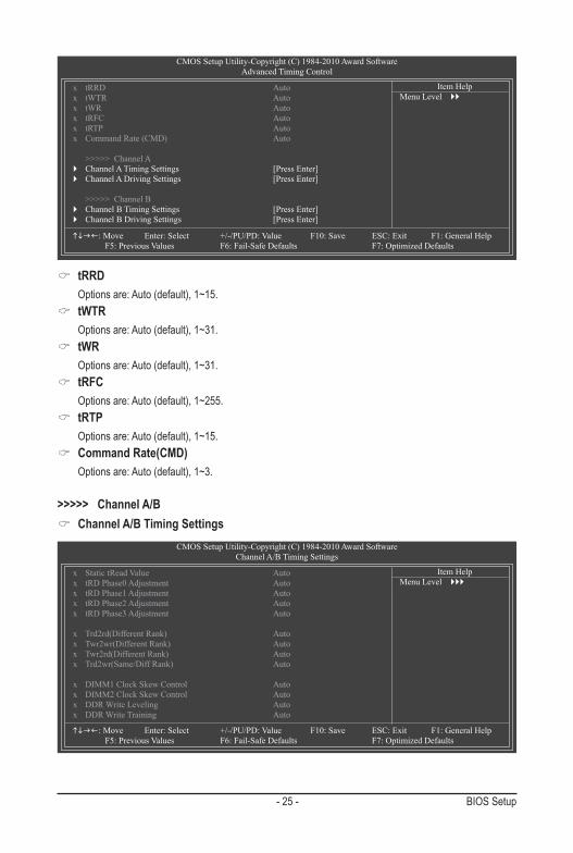
tRRD Options are: Auto (default), 1~15.
tWTR Options are: Auto (default), 1~31.
tWR Options are: Auto (default), 1~31.
tRFC Options are: Auto (default), 1~255.
tRTP Options are: Auto (default), 1~15.
Command Rate(CMD) Options are: Auto (default), 1~3.
>>>>> Channel A/B Channel A/B Timing Settings
CMOS Setup Utility-Copyright (C) 1984-2010 Award SoftwareAdvanced Timing Control
: Move Enter: Select +/-/PU/PD: Value F10: Save ESC: Exit F1: General Help F5: Previous Values F6: Fail-Safe Defaults F7: Optimized Defaults
Item HelpMenu Level
x tRRD Autox tWTR Autox tWR Autox tRFC Autox tRTP Autox Command Rate (CMD) Auto
>>>>> Channel A Channel A Timing Settings [Press Enter] Channel A Driving Settings [Press Enter]
>>>>> Channel B Channel B Timing Settings [Press Enter] Channel B Driving Settings [Press Enter]
CMOS Setup Utility-Copyright (C) 1984-2010 Award SoftwareChannel A/B Timing Settings
: Move Enter: Select +/-/PU/PD: Value F10: Save ESC: Exit F1: General Help F5: Previous Values F6: Fail-Safe Defaults F7: Optimized Defaults
Item HelpMenu Level
x Static tRead Value Autox tRD Phase0 Adjustment Autox tRD Phase1 Adjustment Autox tRD Phase2 Adjustment Autox tRD Phase3 Adjustment Auto
x Trd2rd(Different Rank) Autox Twr2wr(Different Rank) Autox Twr2rd(Different Rank) Autox Trd2wr(Same/Diff Rank) Auto
x DIMM1 Clock Skew Control Autox DIMM2 Clock Skew Control Autox DDR Write Leveling Autox DDR Write Training Auto
BIOS Setup - 26 -
Static tRead Value Options are: Auto (default), 1~15.
tRD Phase0 Adjustment Options are: Auto (default), 0-Normal, 1-Advanced.
tRD Phase1 Adjustment Options are: Auto (default), 0-Normal, 1-Advanced.
tRD Phase2 Adjustment Options are: Auto (default), 0-Normal, 1-Advanced.
tRD Phase3 Adjustment Options are: Auto (default), 0-Normal, 1-Advanced.
Trd2rd(Different Rank) Options are: Auto (default), 1~15.
Twr2wr(Different Rank) Options are: Auto (default), 1~15.
Twr2rd(Different Rank) Options are: Auto (default), 1~15.
Trd2wr(Same/Diff Rank) Options are: Auto (default), 1~15.
DIMM1 Clock Skew Control Options are: Auto (default), +800ps~-700ps.
DIMM2 Clock Skew Control Options are: Auto (default), +800ps~-700ps.
DDR Write Leveling Allows you to determine whether to fine-tune memory parameters to enhance memory compatibility. Auto Lets the BIOS decide whether to enable this function. (Default) Enabled Enables this function to enhance memory compatibility. Disabled Disables this function.
DDR Write Training Allows you to determine whether to fine-tune memory parameters to enhance memory compatibility. Auto Lets the BIOS decide whether to enable this function. (Default) Enabled Enables this function to enhance memory compatibility. Disabled Disables this function.
Channel A/B Driving Settings
- 27 - BIOS Setup
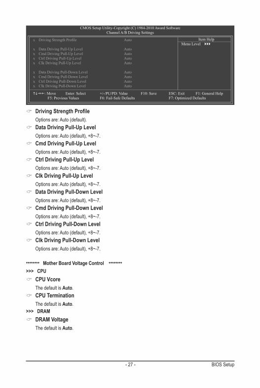
Driving Strength Profile Options are: Auto (default).
Data Driving Pull-Up Level Options are: Auto (default), +8~-7.
Cmd Driving Pull-Up Level Options are: Auto (default), +8~-7.
Ctrl Driving Pull-Up Level Options are: Auto (default), +8~-7.
Clk Driving Pull-Up Level Options are: Auto (default), +8~-7.
Data Driving Pull-Down Level Options are: Auto (default), +8~-7.
Cmd Driving Pull-Down Level Options are: Auto (default), +8~-7.
Ctrl Driving Pull-Down Level Options are: Auto (default), +8~-7.
Clk Driving Pull-Down Level Options are: Auto (default), +8~-7.
******** Mother Board Voltage Control ********>>> CPU
CPU Vcore The default is Auto.
CPU Termination The default is Auto.>>> DRAM
DRAM Voltage The default is Auto.
CMOS Setup Utility-Copyright (C) 1984-2010 Award SoftwareChannel A/B Driving Settings
: Move Enter: Select +/-/PU/PD: Value F10: Save ESC: Exit F1: General Help F5: Previous Values F6: Fail-Safe Defaults F7: Optimized Defaults
Item HelpMenu Level
x DrivingStrengthProfile Auto
x Data Driving Pull-Up Level Autox Cmd Driving Pull-Up Level Autox Ctrl Driving Pull-Up Level Autox Clk Driving Pull-Up Level Auto
x Data Driving Pull-Down Level Autox Cmd Driving Pull-Down Level Autox Ctrl Driving Pull-Down Level Autox Clk Driving Pull-Down Level Auto
BIOS Setup - 28 -
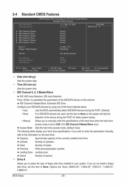
Date (mm:dd:yy) Sets the system date.
Time (hh:mm:ss) Sets the system time.
IDE Channel 0, 2, 3 Master/Slave IDE HDD Auto-Detection, IDE Auto-Detection Press <Enter> to autodetect the parameters of the IDE/SATA device on this channel. IDE Channel 0 Master/Slave, Extended IDE Drive Configure your IDE/SATA devices by using one of the three methods below: •Auto Lets the BIOS automatically detect IDE/SATA devices during the POST. (Default) •None If no IDE/SATA devices are used, set this item to None so the system will skip the
detection of the device during the POST for faster system startup. •Manual Allows you to manually enter the specifications of the hard drive when the hard drive access mode is set to CHS. (For IDE Channel 0 Master/Slave only.) Access Mode Sets the hard drive access mode. (Default: Auto) The following fields display your hard drive specifications. If you wish to enter the parameters manually,
refer to the information on the hard drive. Capacity Approximate capacity of the currently installed hard drive. Cylinder Number of cylinders. Head Number of heads. Precomp Write precompensation cylinder. Landing Zone Landing zone. Sector Number of sectors.
Drive A Allows you to select the type of floppy disk drive installed in your system. If you do not install a floppy
disk drive, set this item to None. Options are: None, 360K/5.25", 1.2M/5.25", 720K/3.5", 1.44M/3.5", 2.88M/3.5".
2-4 Standard CMOS FeaturesCMOS Setup Utility-Copyright (C) 1984-2010 Award Software
Standard CMOS Features
Date (mm:dd:yy) Mon, May 10 2010 Time (hh:mm:ss) 22:31:24
IDE Channel 0 Master [None] IDE Channel 0 Slave [None] IDE Channel 2 Master [None] IDE Channel 2 Slave [None] IDE Channel 3 Master [None] IDE Channel 3 Slave [None]
Drive A [1.44M, 3.5"] Floppy 3 Mode Support [Disabled]
Halt On [All, But Keyboard]
Base Memory 640K Extended Memory 2012M Total Memory 2014M
: Move Enter: Select +/-/PU/PD: Value F10: Save ESC: Exit F1: General Help F5: Previous Values F6: Fail-Safe Defaults F7: Optimized Defaults
Item HelpMenu Level
- 29 - BIOS Setup
Floppy 3 Mode Support Allows you to specify whether the installed floppy disk drive is 3-mode floppy disk drive, a Japanese
standard floppy disk drive. Options are: Disabled (default), Drive A. Halt On
Allows you to determine whether the system will stop for an error during the POST. Options are: "All Errors," "No Errors," "All, But Keyboard" (default), "All, But Diskette," "All, But Disk/Key."
Memory These fields are read-only and are determined by the BIOS POST.
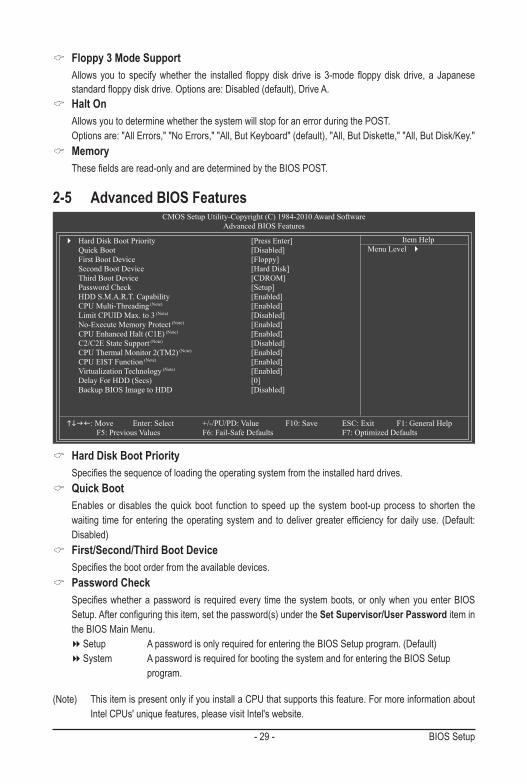
2-5 Advanced BIOS FeaturesCMOS Setup Utility-Copyright (C) 1984-2010 Award Software
Advanced BIOS Features
Hard Disk Boot Priority [Press Enter] Quick Boot [Disabled] First Boot Device [Floppy] Second Boot Device [Hard Disk] Third Boot Device [CDROM] Password Check [Setup] HDD S.M.A.R.T. Capability [Enabled] CPU Multi-Threading (Note) [Enabled] Limit CPUID Max. to 3 (Note) [Disabled] No-Execute Memory Protect (Note) [Enabled] CPU Enhanced Halt (C1E) (Note) [Enabled] C2/C2E State Support (Note) [Disabled] CPU Thermal Monitor 2(TM2) (Note) [Enabled] CPU EIST Function (Note) [Enabled] Virtualization Technology (Note) [Enabled] Delay For HDD (Secs) [0] Backup BIOS Image to HDD [Disabled]
: Move Enter: Select +/-/PU/PD: Value F10: Save ESC: Exit F1: General Help F5: Previous Values F6: Fail-Safe Defaults F7: Optimized Defaults
Item HelpMenu Level
Hard Disk Boot Priority Specifies the sequence of loading the operating system from the installed hard drives.
Quick Boot Enables or disables the quick boot function to speed up the system boot-up process to shorten the
waiting time for entering the operating system and to deliver greater efficiency for daily use. (Default: Disabled)
First/Second/Third Boot Device Specifies the boot order from the available devices.
Password Check Specifies whether a password is required every time the system boots, or only when you enter BIOS
Setup. After configuring this item, set the password(s) under the Set Supervisor/User Password item in the BIOS Main Menu.
Setup A password is only required for entering the BIOS Setup program. (Default) System A password is required for booting the system and for entering the BIOS Setup program.
(Note) This item is present only if you install a CPU that supports this feature. For more information about Intel CPUs' unique features, please visit Intel's website.
BIOS Setup - 30 -
(Note) This item is present only if you install a CPU that supports this feature. For more information about Intel CPUs' unique features, please visit Intel's website.
HDD S.M.A.R.T. Capability Enables or disables the S.M.A.R.T. (Self Monitoring and Reporting Technology) capability of your hard
drive. This feature allows your system to report read/write errors of the hard drive and to issue warnings when a third party hardware monitor utility is installed. (Default: Enabled)
CPU Multi-Threading (Note)
Allows you to determine whether to enable all CPU cores and multi-threading function when using an Intel CPU that supports multi-core technology. This feature only works for operating systems that support multi-processor mode.
Enabled Enables all CPU cores and multi-threading capability. (Default) Disabled Enables only one CPU core.
Limit CPUID Max. to 3 (Note)
Allows you to determine whether to limit CPUID maximum value. Set this item to Disabled for Windows XP operating system; set this item to Enabled for legacy operating system such as Windows NT4.0. (Default: Disabled)
No-Execute Memory Protect (Note)
Enables or disables Intel Execute Disable Bit function. This function may enhance protection for the computer, reducing exposure to viruses and malicious buffer overflow attacks when working with its supporting software and system. (Default: Enabled)
CPU Enhanced Halt (C1E) (Note)
Enables or disables Intel CPU Enhanced Halt (C1E) function, a CPU power-saving function in system halt state. When enabled, the CPU core frequency and voltage will be reduced during system halt state to decrease power consumption. (Default: Enabled)
C2/C2E State Support (Note)
Allows you to determine whether to let the CPU enter C2/C2E mode in system halt state. When enabled, the CPU core frequency and voltage will be reduced during system halt state to descrease power con-sumption. (Default: Disabled)
CPU Thermal Monitor 2 (TM2) (Note)
Enables or disables Intel CPU Thermal Monitor (TM2) function, a CPU overheating protection function. When enabled, the CPU core frequency and voltage will be reduced when the CPU is overheated. (Default: Enabled)
CPU EIST Function (Note)
Enables or disables Enhanced Intel SpeedStep Technology (EIST). Depending on CPU loading, Intel EIST technology can dynamically and effectively lower the CPU voltage and core frequency to decrease average power consumption and heat production. (Default: Enabled)
Virtualization Technology (Note)
Enables or disables Intel Virtualization Technology. Virtualization enhanced by Intel Virtualization Technology will allow a platform to run multiple operating systems and applications in independent partitions. With virtualization, one computer system can function as multiple virtual systems. (Default: Enabled)
- 31 - BIOS Setup
Delay For HDD (Secs) Allows you to set a delay time for the BIOS to initialize the hard drive as the system boots up. The
adjustable range is from 0 to 15 seconds. (Default: 0) Backup BIOS Image to HDD
Allows the system to copy the BIOS image file to the hard drive. If the system BIOS is corrupted, it will be recovered from this image file. (Default: Disabled)
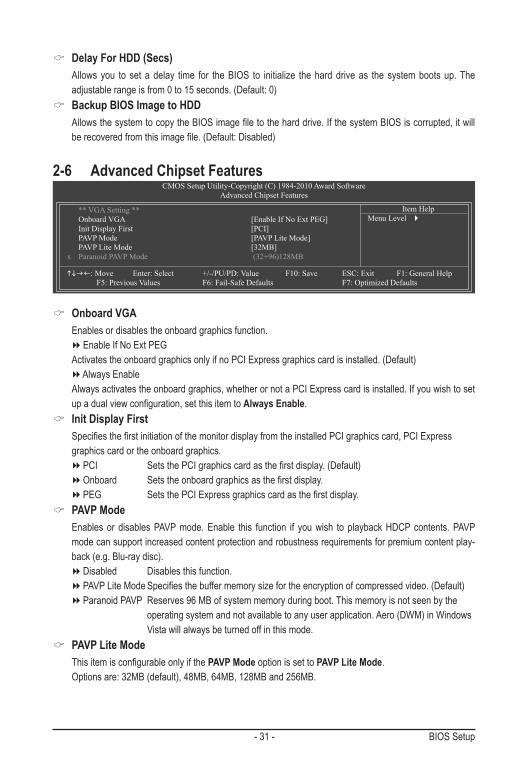
2-6 Advanced Chipset FeaturesCMOS Setup Utility-Copyright (C) 1984-2010 Award Software
Advanced Chipset Features
** VGA Setting ** Onboard VGA [Enable If No Ext PEG] Init Display First [PCI] PAVP Mode [PAVP Lite Mode] PAVP Lite Mode [32MB]x Paranoid PAVP Mode (32+96)128MB
: Move Enter: Select +/-/PU/PD: Value F10: Save ESC: Exit F1: General Help F5: Previous Values F6: Fail-Safe Defaults F7: Optimized Defaults
Item HelpMenu Level
Onboard VGA Enables or disables the onboard graphics function. Enable If No Ext PEG Activates the onboard graphics only if no PCI Express graphics card is installed. (Default) Always Enable Always activates the onboard graphics, whether or not a PCI Express card is installed. If you wish to set
up a dual view configuration, set this item to Always Enable. Init Display First
Specifies the first initiation of the monitor display from the installed PCI graphics card, PCI Express graphics card or the onboard graphics.
PCI Sets the PCI graphics card as the first display. (Default) Onboard Sets the onboard graphics as the first display. PEG Sets the PCI Express graphics card as the first display.
PAVP Mode Enables or disables PAVP mode. Enable this function if you wish to playback HDCP contents. PAVP
mode can support increased content protection and robustness requirements for premium content play-back (e.g. Blu-ray disc).
Disabled Disables this function. PAVP Lite Mode Specifies the buffer memory size for the encryption of compressed video. (Default) Paranoid PAVP Reserves 96 MB of system memory during boot. This memory is not seen by the operating system and not available to any user application. Aero (DWM) in Windows Vista will always be turned off in this mode.
PAVP Lite Mode This item is configurable only if the PAVP Mode option is set to PAVP Lite Mode. Options are: 32MB (default), 48MB, 64MB, 128MB and 256MB.
BIOS Setup - 32 -
Paranoid PAVP Mode This item is configurable only if the PAVP Mode option is set to Paranoid PAVP. Options are: (32+96)128MB (default), (48+96) Round to 160MB, (64+96)160MB, (128+96)224MB and
(256+96)352MB. The table below shows the supported features of the PAVP Lite and Paranoid modes.
Feature PAVP Lite PAVP ParanoidCompressed video buffer is encrypted Yes YesHardware 128-bit AES decryption Yes YesProtected memory No Yes (96 MB reserved during boot)
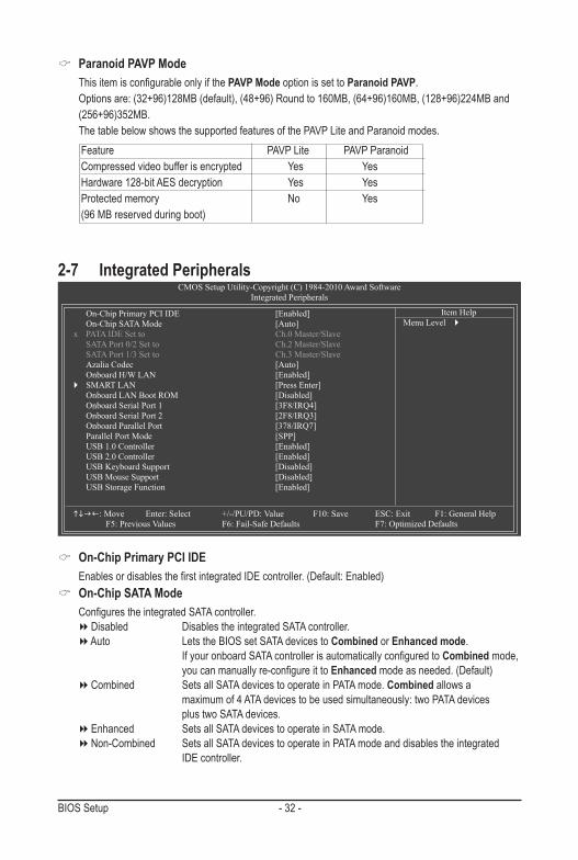
2-7 Integrated PeripheralsCMOS Setup Utility-Copyright (C) 1984-2010 Award Software
Integrated Peripherals
On-Chip Primary PCI IDE [Enabled] On-Chip SATA Mode [Auto]x PATA IDE Set to Ch.0 Master/Slave SATA Port 0/2 Set to Ch.2 Master/Slave SATA Port 1/3 Set to Ch.3 Master/Slave Azalia Codec [Auto] Onboard H/W LAN [Enabled] SMART LAN [Press Enter] Onboard LAN Boot ROM [Disabled] Onboard Serial Port 1 [3F8/IRQ4] Onboard Serial Port 2 [2F8/IRQ3] Onboard Parallel Port [378/IRQ7] Parallel Port Mode [SPP] USB 1.0 Controller [Enabled] USB 2.0 Controller [Enabled] USB Keyboard Support [Disabled] USB Mouse Support [Disabled] USB Storage Function [Enabled]
: Move Enter: Select +/-/PU/PD: Value F10: Save ESC: Exit F1: General Help F5: Previous Values F6: Fail-Safe Defaults F7: Optimized Defaults
Item HelpMenu Level
On-Chip Primary PCI IDE Enables or disables the first integrated IDE controller. (Default: Enabled)
On-Chip SATA Mode Configures the integrated SATA controller. Disabled Disables the integrated SATA controller. Auto Lets the BIOS set SATA devices to Combined or Enhanced mode. If your onboard SATA controller is automatically configured to Combined mode, you can manually re-configure it to Enhanced mode as needed. (Default) Combined Sets all SATA devices to operate in PATA mode. Combined allows a maximum of 4 ATA devices to be used simultaneously: two PATA devices plus two SATA devices. Enhanced Sets all SATA devices to operate in SATA mode. Non-Combined Sets all SATA devices to operate in PATA mode and disables the integrated IDE controller.
- 33 - BIOS Setup
PATA IDE Set to This item is configurable only if the On-Chip SATA Mode is set to Combined. Ch.0 Master/Slave Sets the IDE channels to Ch. 0 Master/Slave. (Default) Ch.1 Master/Slave Sets the IDE channels to Ch. 1 Master/Slave.
SATA Port 0/2 Set to This value is dependent on the On-Chip SATA Mode and PATA IDE Set to settings. When PATA IDE Set to is configured to Ch. 1 Master/Slave, this option will be automatically set to Ch. 0 Master/Slave.
SATA Port 1/3 Set to This value is dependent on the On-Chip SATA Mode and PATA IDE Set to settings. When PATA IDE Set to is configured to Ch. 0 Master/Slave, this option will be automatically set to Ch. 1 Master/Slave.
Azalia Codec Enables or disables the onboard audio function. (Default: Auto) If you wish to install a 3rd party add-in audio card instead of using the onboard audio, set this item to
Disabled. Onboard H/W LAN
Enables or disables the onboard LAN function. (Default: Enabled) If you wish to install a 3rd party add-in network card instead of using the onboard LAN, set this item to
Disabled.
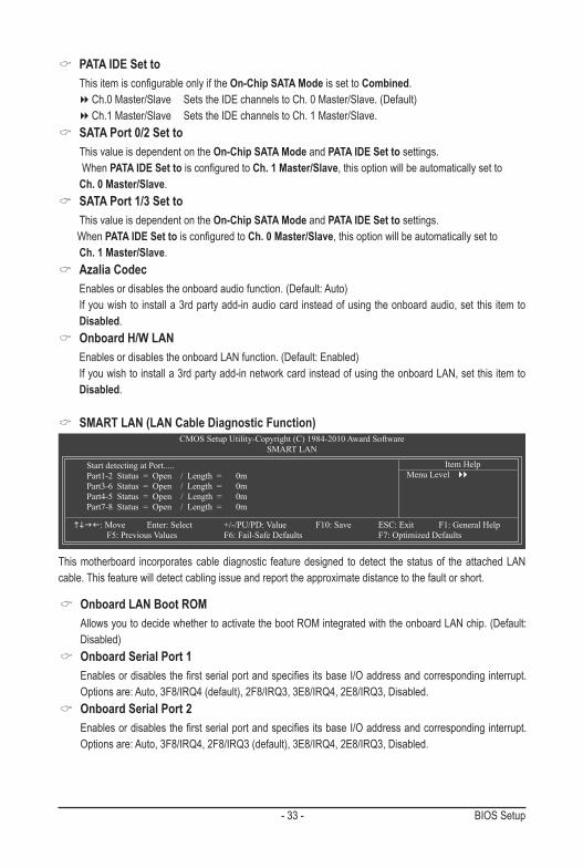
SMART LAN (LAN Cable Diagnostic Function)CMOS Setup Utility-Copyright (C) 1984-2010 Award Software
SMART LAN
Start detecting at Port..... Part1-2 Status = Open / Length = 0m Part3-6 Status = Open / Length = 0m Part4-5 Status = Open / Length = 0m Part7-8 Status = Open / Length = 0m
: Move Enter: Select +/-/PU/PD: Value F10: Save ESC: Exit F1: General Help F5: Previous Values F6: Fail-Safe Defaults F7: Optimized Defaults
Item HelpMenu Level
This motherboard incorporates cable diagnostic feature designed to detect the status of the attached LAN cable. This feature will detect cabling issue and report the approximate distance to the fault or short.
Onboard LAN Boot ROM Allows you to decide whether to activate the boot ROM integrated with the onboard LAN chip. (Default:
Disabled) Onboard Serial Port 1
Enables or disables the first serial port and specifies its base I/O address and corresponding interrupt. Options are: Auto, 3F8/IRQ4 (default), 2F8/IRQ3, 3E8/IRQ4, 2E8/IRQ3, Disabled.
Onboard Serial Port 2 Enables or disables the first serial port and specifies its base I/O address and corresponding interrupt.
Options are: Auto, 3F8/IRQ4, 2F8/IRQ3 (default), 3E8/IRQ4, 2E8/IRQ3, Disabled.
BIOS Setup - 34 -
Onboard Parallel Port Enables or disables the onboard parallel port (LPT) and specifies its base I/O address and correspond-
ing interrupt. Options are: 378/IRQ7 (default), 278/IRQ5, 3BC/IRQ7, Disabled. Parallel Port Mode
Selects an operating mode for the onboard parallel (LPT) port. Options are: SPP (Standard Parallel Port)(default), EPP (Enhanced Parallel Port), ECP (Extended Capabilities Port), ECP+EPP.
USB 1.0 Controller Enables or disables the integrated USB controller. (Default: Enabled) Disabled will turn off all of the USB functionalities below.
USB 2.0 Controller Enables or disables the integrated USB 2.0 controller. (Default: Enabled)
USB Keyboard Function Allows USB keyboard to be used in MS-DOS. (Default: Disabled)
USB Mouse Function Allows USB mouse to be used in MS-DOS. (Default: Disabled)
USB Storage Function Determines whether to detect USB storage devices, including USB flash drives and USB hard drives
during the POST. (Default: Enabled)
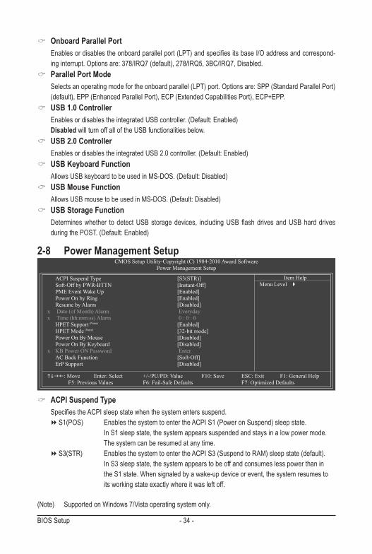
2-8 Power Management SetupCMOS Setup Utility-Copyright (C) 1984-2010 Award Software
Power Management Setup
ACPI Suspend Type [S3(STR)] Soft-Off by PWR-BTTN [Instant-Off] PME Event Wake Up [Enabled] Power On by Ring [Enabled] Resume by Alarm [Disabled]x Date (of Month) Alarm Everydayx Time (hh:mm:ss) Alarm 0 : 0 : 0 HPET Support (Note) [Enabled] HPET Mode (Note) [32-bit mode] Power On By Mouse [Disabled] Power On By Keyboard [Disabled]x KB Power ON Password Enter AC Back Function [Soft-Off] ErP Support [Disabled]
: Move Enter: Select +/-/PU/PD: Value F10: Save ESC: Exit F1: General Help F5: Previous Values F6: Fail-Safe Defaults F7: Optimized Defaults
Item HelpMenu Level
ACPI Suspend Type Specifies the ACPI sleep state when the system enters suspend. S1(POS) Enables the system to enter the ACPI S1 (Power on Suspend) sleep state.
In S1 sleep state, the system appears suspended and stays in a low power mode. The system can be resumed at any time.
S3(STR) Enables the system to enter the ACPI S3 (Suspend to RAM) sleep state (default). In S3 sleep state, the system appears to be off and consumes less power than in the S1 state. When signaled by a wake-up device or event, the system resumes to its working state exactly where it was left off.
(Note) Supported on Windows 7/Vista operating system only.
- 35 - BIOS Setup
(Note) Supported on Windows 7/Vista operating system only.
Soft-Off by PWR-BTTN Configures the way to turn off the computer in MS-DOS mode using the power button. Instant-Off Press the power button and then the system will be turned off instantly. (Default) Delay 4 Sec. Press and hold the power button for 4 seconds to turn off the system. If the power
button is pressed for less than 4 seconds, the system will enter suspend mode. PME Event Wake Up
Allows the system to be awakened from an ACPI sleep state by a wake-up signal from a PCI or PCIe device. Note: To use this function, you need an ATX power supply providing at least 1A on the +5VSB lead. (Default: Enabled)
Power On by Ring Allows the system to be awakened from an ACPI sleep state by a wake-up signal from a modem that
supports wake-up function. (Default: Enabled) Resume by Alarm
Determines whether to power on the system at a desired time. (Default: Disabled) If enabled, set the date and time as following: Date (of Month) Alarm: Turn on the system at a specific time on each day or on a specific day in a
month. Time (hh: mm: ss) Alarm: Set the time at which the system will be powered on automatically. Note: When using this function, avoid inadequate shutdown from the operating system or removal of the
AC power, or the settings may not be effective. HPET Support (Note)
Enables or disables High Precision Event Timer (HPET) for Windows 7/Vista operating system. (Default: Enabled)
HPET Mode (Note)
Allows you to select the HPET mode for your Windows 7/Vista operating system. This item is configu-rable only if the HPET Support is set to Enabled. (Default: 32-bit mode)
Power On By Mouse Allows the system to be turned on by a PS/2 mouse wake-up event. (Default: Disabled) Note: To use this function, you need an ATX power supply providing at least 1A on the +5VSB lead. Double Click Double click on left button on the PS/2 mouse to turn on the system.
Power On By Keyboard Allows the system to be turned on by a PS/2 keyboard wake-up event. (Default: Disabled) Note: you need an ATX power supply providing at least 1A on the +5VSB lead. Password Set a password with 1~5 characters to turn on the system. Keyboard 98 Press POWER button on the Windows 98 keyboard to turn on the system.
KB Power ON Password Set the password when Power On by Keyboard is set to Password. Press <Enter> on this item and set
a password with up to 5 characters and then press <Enter> to accept. To turn on the system, enter the password and press <Enter>.
Note: To cancel the password, press <Enter> on this item. When prompted for the password, press <Enter> again without entering the password to clear the password settings.
BIOS Setup - 36 -
AC Back Function Determines the state of the system after the return of power from an AC power loss. Soft-Off The system stays off upon the return of the AC power. (Default) Full-On The system is turned on upon the return of the AC power. Memory The system returns to its last known awake state upon the return of the AC power.
ErP Support Determines whether to let the system consume less than 1W power in S5 (shutdown) state. (Default:
Disabled) Note: When this item is set to Enabled, the following four functions will become unavailable: PME event wake up, power on by mouse, power on by keyboard, and wake on LAN.
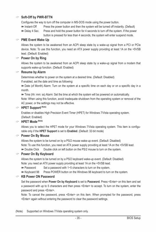
2-9 PnP/PCI ConfigurationsCMOS Setup Utility-Copyright (C) 1984-2010 Award Software
PnP/PCIConfigurations
PCI1 IRQ Assignment [Auto] PCI2 IRQ Assignment [Auto]
: Move Enter: Select +/-/PU/PD: Value F10: Save ESC: Exit F1: General Help F5: Previous Values F6: Fail-Safe Defaults F7: Optimized Defaults
Item HelpMenu Level
PCI1/2 IRQ Assignment Auto BIOS auto-assigns IRQ to the first/second PCI slot. (Default) 3,4,5,7,9,10,11,12,14,15 Assigns IRQ 3,4,5,7,9,10,11,12,14,15 to the first/second PCI slot.
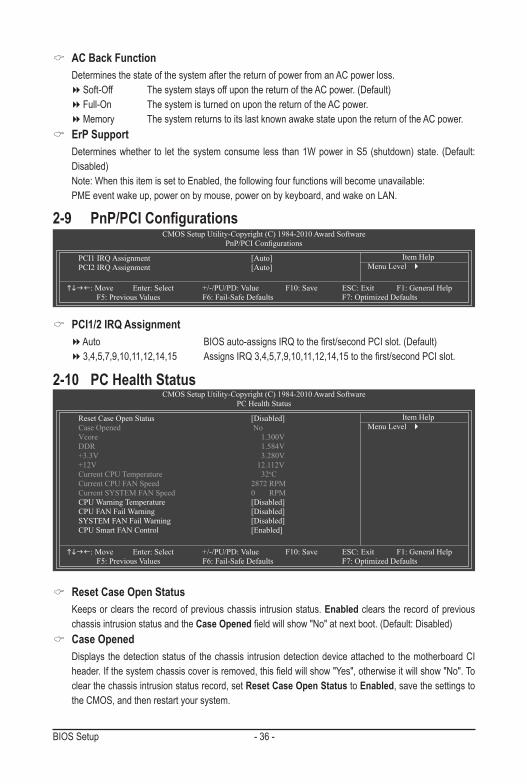
2-10 PC Health Status
Reset Case Open Status [Disabled] Case Opened No Vcore 1.300V DDR 1.584V +3.3V 3.280V +12V 12.112V Current CPU Temperature 32oC Current CPU FAN Speed 2872 RPM Current SYSTEM FAN Speed 0 RPM CPU Warning Temperature [Disabled] CPU FAN Fail Warning [Disabled] SYSTEM FAN Fail Warning [Disabled] CPU Smart FAN Control [Enabled]
: Move Enter: Select +/-/PU/PD: Value F10: Save ESC: Exit F1: General Help F5: Previous Values F6: Fail-Safe Defaults F7: Optimized Defaults
CMOS Setup Utility-Copyright (C) 1984-2010 Award SoftwarePC Health Status
Item HelpMenu Level
Reset Case Open Status Keeps or clears the record of previous chassis intrusion status. Enabled clears the record of previous
chassis intrusion status and the Case Opened field will show "No" at next boot. (Default: Disabled) Case Opened
Displays the detection status of the chassis intrusion detection device attached to the motherboard CI header. If the system chassis cover is removed, this field will show "Yes", otherwise it will show "No". To clear the chassis intrusion status record, set Reset Case Open Status to Enabled, save the settings to the CMOS, and then restart your system.
- 37 - BIOS Setup
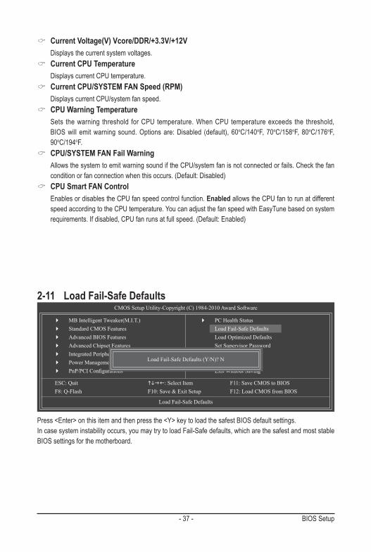
Current Voltage(V) Vcore/DDR/+3.3V/+12V Displays the current system voltages.
Current CPU Temperature Displays current CPU temperature.
Current CPU/SYSTEM FAN Speed (RPM) Displays current CPU/system fan speed.
CPU Warning Temperature Sets the warning threshold for CPU temperature. When CPU temperature exceeds the threshold,
BIOS will emit warning sound. Options are: Disabled (default), 60oC/140oF, 70oC/158oF, 80oC/176oF, 90oC/194oF.
CPU/SYSTEM FAN Fail Warning Allows the system to emit warning sound if the CPU/system fan is not connected or fails. Check the fan
condition or fan connection when this occurs. (Default: Disabled) CPU Smart FAN Control
Enables or disables the CPU fan speed control function. Enabled allows the CPU fan to run at different speed according to the CPU temperature. You can adjust the fan speed with EasyTune based on system requirements. If disabled, CPU fan runs at full speed. (Default: Enabled)
Press <Enter> on this item and then press the <Y> key to load the safest BIOS default settings. In case system instability occurs, you may try to load Fail-Safe defaults, which are the safest and most stable BIOS settings for the motherboard.
2-11 Load Fail-Safe DefaultsCMOS Setup Utility-Copyright (C) 1984-2010 Award Software
Load Fail-Safe Defaults
MB Intelligent Tweaker(M.I.T.) Standard CMOS Features Advanced BIOS Features Advanced Chipset Features Integrated Peripherals Power Management Setup PnP/PCIConfigurations
ESC: Quit : Select Item F11: Save CMOS to BIOS F8: Q-Flash F10: Save & Exit Setup F12: Load CMOS from BIOS
PC Health Status Load Fail-Safe Defaults Load Optimized Defaults Set Supervisor Password Set User Password Save & Exit Setup Exit Without Saving
Load Fail-Safe Defaults (Y/N)? N
BIOS Setup - 38 -
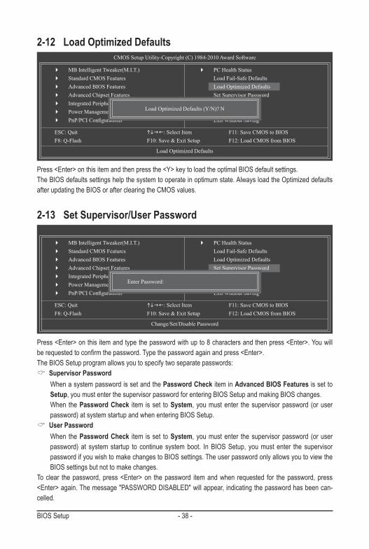
Press <Enter> on this item and type the password with up to 8 characters and then press <Enter>. You will be requested to confirm the password. Type the password again and press <Enter>. The BIOS Setup program allows you to specify two separate passwords:
Supervisor Password When a system password is set and the Password Check item in Advanced BIOS Features is set to
Setup, you must enter the supervisor password for entering BIOS Setup and making BIOS changes. When the Password Check item is set to System, you must enter the supervisor password (or user
password) at system startup and when entering BIOS Setup. User Password
When the Password Check item is set to System, you must enter the supervisor password (or user password) at system startup to continue system boot. In BIOS Setup, you must enter the supervisor password if you wish to make changes to BIOS settings. The user password only allows you to view the BIOS settings but not to make changes.
To clear the password, press <Enter> on the password item and when requested for the password, press <Enter> again. The message "PASSWORD DISABLED" will appear, indicating the password has been can-celled.
2-13 Set Supervisor/User PasswordCMOS Setup Utility-Copyright (C) 1984-2010 Award Software
Change/Set/Disable Password
MB Intelligent Tweaker(M.I.T.) Standard CMOS Features Advanced BIOS Features Advanced Chipset Features Integrated Peripherals Power Management Setup PnP/PCIConfigurations
ESC: Quit : Select Item F11: Save CMOS to BIOS F8: Q-Flash F10: Save & Exit Setup F12: Load CMOS from BIOS
PC Health Status Load Fail-Safe Defaults Load Optimized Defaults Set Supervisor Password Set User Password Save & Exit Setup Exit Without Saving
Enter Password:
Press <Enter> on this item and then press the <Y> key to load the optimal BIOS default settings. The BIOS defaults settings help the system to operate in optimum state. Always load the Optimized defaults after updating the BIOS or after clearing the CMOS values.
2-12 Load Optimized DefaultsCMOS Setup Utility-Copyright (C) 1984-2010 Award Software
Load Optimized Defaults
MB Intelligent Tweaker(M.I.T.) Standard CMOS Features Advanced BIOS Features Advanced Chipset Features Integrated Peripherals Power Management Setup PnP/PCIConfigurations
ESC: Quit : Select Item F11: Save CMOS to BIOS F8: Q-Flash F10: Save & Exit Setup F12: Load CMOS from BIOS
PC Health Status Load Fail-Safe Defaults Load Optimized Defaults Set Supervisor Password Set User Password Save & Exit Setup Exit Without Saving
Load Optimized Defaults (Y/N)? N
- 39 - BIOS Setup
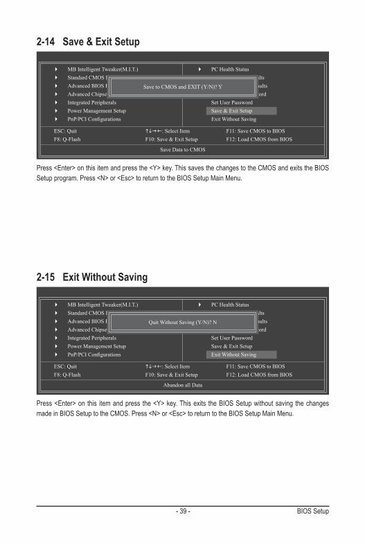
Press <Enter> on this item and press the <Y> key. This saves the changes to the CMOS and exits the BIOS Setup program. Press <N> or <Esc> to return to the BIOS Setup Main Menu.
2-14 Save & Exit Setup
Press <Enter> on this item and press the <Y> key. This exits the BIOS Setup without saving the changes made in BIOS Setup to the CMOS. Press <N> or <Esc> to return to the BIOS Setup Main Menu.
2-15 Exit Without Saving
CMOS Setup Utility-Copyright (C) 1984-2010 Award Software
Save Data to CMOS
MB Intelligent Tweaker(M.I.T.) Standard CMOS Features Advanced BIOS Features Advanced Chipset Features Integrated Peripherals Power Management Setup PnP/PCIConfigurations
ESC: Quit : Select Item F11: Save CMOS to BIOS F8: Q-Flash F10: Save & Exit Setup F12: Load CMOS from BIOS
PC Health Status Load Fail-Safe Defaults Load Optimized Defaults Set Supervisor Password Set User Password Save & Exit Setup Exit Without Saving
Save to CMOS and EXIT (Y/N)? Y
CMOS Setup Utility-Copyright (C) 1984-2010 Award Software
Abandon all Data
MB Intelligent Tweaker(M.I.T.) Standard CMOS Features Advanced BIOS Features Advanced Chipset Features Integrated Peripherals Power Management Setup PnP/PCIConfigurations
ESC: Quit : Select Item F11: Save CMOS to BIOS F8: Q-Flash F10: Save & Exit Setup F12: Load CMOS from BIOS
PC Health Status Load Fail-Safe Defaults Load Optimized Defaults Set Supervisor Password Set User Password Save & Exit Setup Exit Without Saving
Quit Without Saving (Y/N)? N
BIOS Setup - 40 -
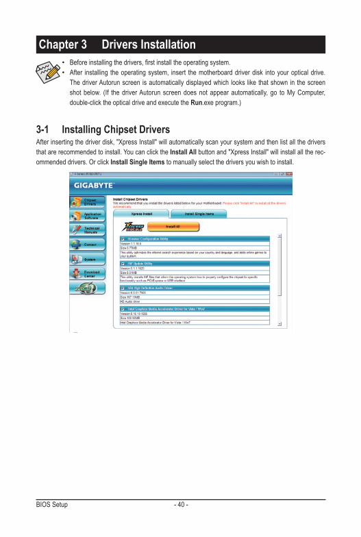
3-1 Installing Chipset Drivers
Chapter 3 Drivers Installation• Before installing the drivers, first install the operating system.• After installing the operating system, insert the motherboard driver disk into your optical drive.
The driver Autorun screen is automatically displayed which looks like that shown in the screen shot below. (If the driver Autorun screen does not appear automatically, go to My Computer, double-click the optical drive and execute the Run.exe program.)
After inserting the driver disk, "Xpress Install" will automatically scan your system and then list all the drivers that are recommended to install. You can click the Install All button and "Xpress Install" will install all the rec-ommended drivers. Or click Install Single Items to manually select the drivers you wish to install.

- 41 - Appendix
Regulatory Statements
Regulatory NoticesThis document must not be copied without our written permission, and the contents there of must not be imparted to a third party nor be used for any unauthorized purpose. Contravention will be prosecuted. We believe that the information contained herein was accurate in all respects at the time of printing. GIGABYTE cannot, however, assume any responsibility for errors or omissions in this text. Also note that the informa-tion in this document is subject to change without notice and should not be construed as a commitment by GIGABYTE.
Our Commitment to Preserving the EnvironmentIn addition to high-efficiency performance, all GIGABYTE motherboards fulfill European Union regulations for RoHS (Restriction of Certain Hazardous Substances in Electrical and Electronic Equipment) and WEEE (Waste Electrical and Electronic Equipment) environmental directives, as well as most major worldwide safety requirements. To prevent releases of harmful substances into the environment and to maximize the use of our natural resources, GIGABYTE provides the following information on how you can responsibly recycle or reuse most of the materials in your "end of life" product.
Restriction of Hazardous Substances (RoHS) Directive StatementGIGABYTE products have not intended to add and safe from hazardous substances (Cd, Pb, Hg, Cr+6, PBDE and PBB). The parts and components have been carefully selected to meet RoHS requirement. More-over, we at GIGABYTE are continuing our efforts to develop products that do not use internationally banned toxic chemicals.
Waste Electrical & Electronic Equipment (WEEE) Directive StatementGIGABYTE will fulfill the national laws as interpreted from the 2002/96/EC WEEE (Waste Electrical and Elec-tronic Equipment) directive. The WEEE Directive specifies the treatment, collection, recycling and disposal of electric and electronic devices and their components. Under the Directive, used equipment must be marked, collected separately, and disposed of properly.
WEEE Symbol StatementThe symbol shown below is on the product or on its packaging, which indicates that this product must not be disposed of with other waste. Instead, the device should be taken to the waste collection centers for activation of the treatment, collection, recycling and disposal procedure. The separate collection and recycling of your waste equipment at the time of disposal will help to conserve natural resources and ensure that it is recycled in a manner that protects human health
and the environment. For more information about where you can drop off your waste equipment for recycling, please contact your local government office, your household waste disposal service or where you purchased the product for details of environmentally safe recycling.w When your electrical or electronic equipment is no longer useful to you, "take it back" to your local or
regional waste collection administration for recycling.w If you need further assistance in recycling, reusing in your "end of life" product, you may contact us at the
Customer Care number listed in your product's user's manual and we will be glad to help you with your effort.

Appendix - 42 -
Finally, we suggest that you practice other environmentally friendly actions by understanding and using the energy-saving features of this product (where applicable), recycling the inner and outer packaging (including shipping containers) this product was delivered in, and by disposing of or recycling used batteries properly. With your help, we can reduce the amount of natural resources needed to produce electrical and electronic equipment, minimize the use of landfills for the disposal of "end of life" products, and generally improve our quality of life by ensuring that potentially hazardous substances are not released into the environment and are disposed of properly.
China Restriction of Hazardous Substances TableThe following table is supplied in compliance with China's Restriction of Hazardous Substances (China RoHS) requirements:

- 43 - Appendix
Contact Us
GIGA-BYTE TECHNOLOGY CO., LTD.Address: No.6, Bau Chiang Road, Hsin-Tien, Taipei 231, Taiwan TEL: +886-2-8912-4000, FAX: +886-2-8912-4003Tech. and Non-Tech. Support (Sales/Marketing) : http://ggts.gigabyte.com.twWEB address (English): http://www.gigabyte.comWEB address (Chinese): http://www.gigabyte.tw
You may go to the GIGABYTE website, select your language in the language list on the top right corner of the website.
• GIGABYTE Global Service System
To submit a technical or non-technical (Sales/Market-ing) question, please link to:http://ggts.gigabyte.com.twThen select your language to enter the system.

Appendix - 44 -
Recommended