Model B Ergometer
Repair, Maintenance & Troubleshooting Instructions
phone: 800.245.5676 int’l: 802.888.6333 fax: 802.888.4791 email: [email protected] web: concept2.com
morrisville, vermont usa 05661
0312
SKEWER RETURN MECHANISM
The following is a step by step description of how to disassemble, inspect and reassemble your return mechanism. Even though you may have to do only part of this procedure to get your machine operating we recommend complete inspection of all the parts while you have the skewer out. Read through the steps to familiarize yourself with what you will be doing. Gather all the necessary tools, clear your workspace and take your time doing the work.
Tools & Materials Required: Hammer Screwdriver Pliers Sharp knifeREMOVAL OF OLD PARTS
1) Pull the handle out a few feet from the chain guide and put the bridge pin through the chain where it emerges from the monorail. This will hold some slack in the chain for you. If your chain has gone slack already, this step will not be necessary. 2) Remove the handle by tapping the rounded end of the U-bolt to dislodge the two (2) 1/4”-20 nylon in-sert stainless steel nuts from the wooden handle. Use a 1/2” wrench to remove the two nuts from the U-bolt. Remove the U-bolt from the handle and chain, take the chain from the sprockets and let it rest on the floor.
3) Remove and save the four (4) #8 machine screws that hold the skewer in the monorail. Slide the skewer out of the front of the machine.
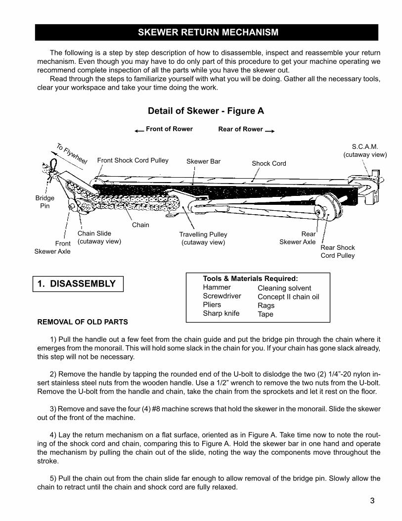
4) Lay the return mechanism on a flat surface, oriented as in Figure A. Take time now to note the rout-ing of the shock cord and chain, comparing this to Figure A. Hold the skewer bar in one hand and operate the mechanism by pulling the chain out of the slide, noting the way the components move throughout the stroke.
5) Pull the chain out from the chain slide far enough to allow removal of the bridge pin. Slowly allow the chain to retract until the chain and shock cord are fully relaxed.
Cleaning solventConcept II chain oilRagsTape
Detail of Skewer - Figure A
To Flywheel
s Front of Rower Rear of Rower r
Front Shock Cord Pulley Skewer Bar Shock Cord
S.C.A.M. (cutaway view)
Bridge Pin
ChainChain Slide (cutaway view)Front
Skewer Axle
Travelling Pulley (cutaway view)
Rear Skewer Axle
Rear Shock Cord Pulley
1. DISASSEMbLy
3
6) Remove the S.C.A.M. (Shock Cord Adjustment Mechanism) from the rear axle and unloop the shock cord from the front and rear shock cord pulleys.
7) Mark the end of the shock cord that is at the S.C.A.M. with a piece of tape, then detach the shock cord from the S.C.A.M. and the travelling pulley by pushing the ends of the cord out of these parts. Set the shock cord and S.C.A.M. aside for later inspection.
8) Now go to the front axle and, with a screwdriver or pliers, ply off the axle retaining clip that is holding the chain slide and chain in place. Pull the chain slide and chain off the axle. Set the chain slide aside for later inspection. The axle clip may be discarded as its purpose is to hold parts in place during assembly and shipping. It is difficult to replace without the right tool, and you will be using the skewer axle screws to serve the same function during assembly.
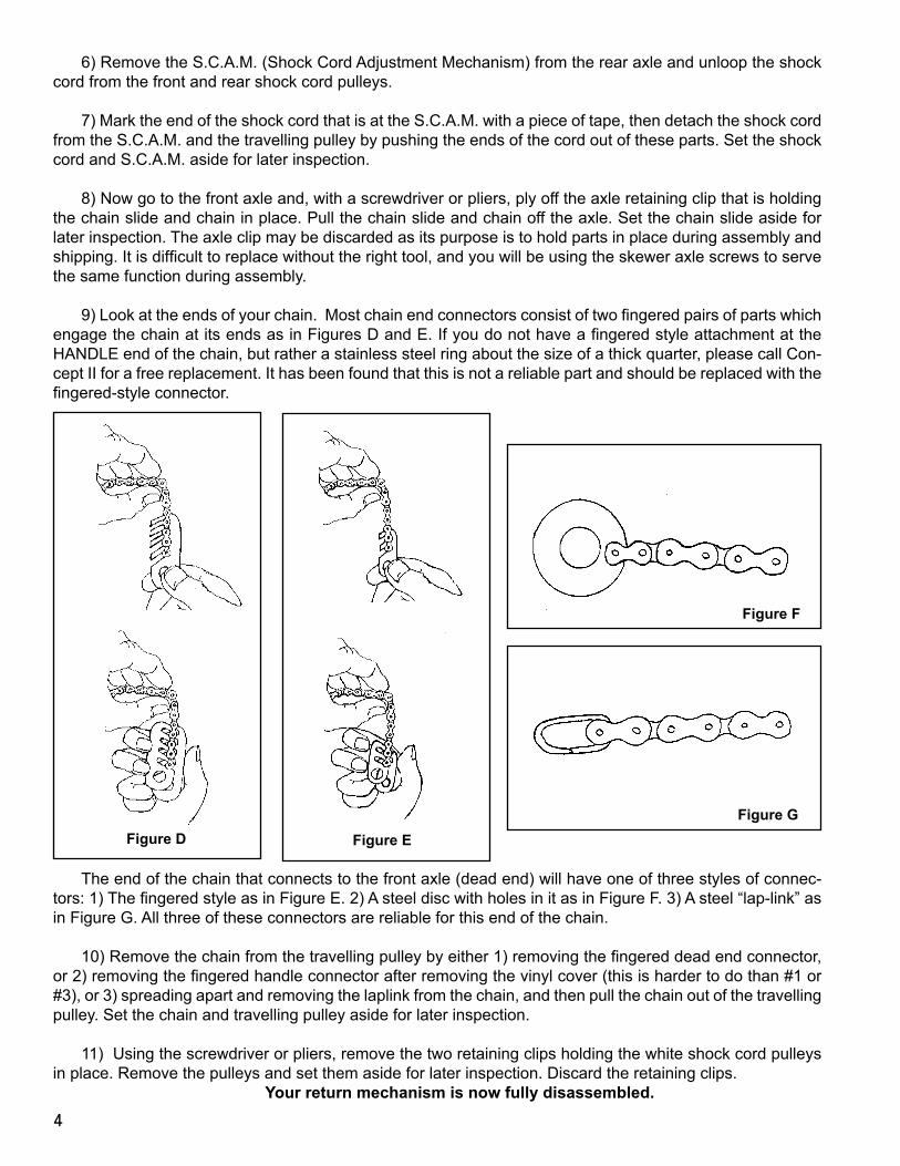
9) Look at the ends of your chain. Most chain end connectors consist of two fingered pairs of parts which engage the chain at its ends as in Figures D and E. If you do not have a fingered style attachment at the HANDLE end of the chain, but rather a stainless steel ring about the size of a thick quarter, please call Con-cept II for a free replacement. It has been found that this is not a reliable part and should be replaced with the fingered-style connector.
The end of the chain that connects to the front axle (dead end) will have one of three styles of connec-tors: 1) The fingered style as in Figure E. 2) A steel disc with holes in it as in Figure F. 3) A steel “lap-link” as in Figure G. All three of these connectors are reliable for this end of the chain.
10) Remove the chain from the travelling pulley by either 1) removing the fingered dead end connector, or 2) removing the fingered handle connector after removing the vinyl cover (this is harder to do than #1 or #3), or 3) spreading apart and removing the laplink from the chain, and then pull the chain out of the travelling pulley. Set the chain and travelling pulley aside for later inspection.
11) Using the screwdriver or pliers, remove the two retaining clips holding the white shock cord pulleys in place. Remove the pulleys and set them aside for later inspection. Discard the retaining clips. your return mechanism is now fully disassembled.
Figure D Figure E
Figure F
Figure G
4
2. INSPECTION OF PARTS
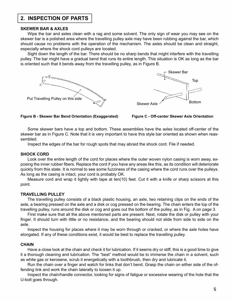
SKEWER bAR & AXLES Wipe the bar and axles clean with a rag and some solvent. The only sign of wear you may see on the skewer bar is a polished area where the travelling pulley axle may have been rubbing against the bar, which should cause no problems with the operation of the mechanism. The axles should be clean and straight, especially where the shock cord pulleys are located. Sight down the length of the bar. There should be no sharp bends that might interfere with the travelling pulley. The bar might have a gradual bend that runs its entire length. This situation is OK as long as the bar is oriented such that it bends away from the travelling pulley, as in Figure B.
Some skewer bars have a top and bottom. These assemblies have the axles located off-center of the skewer bar as in Figure C. Note that it is very important to have this style bar oriented as shown when reas-sembled. Inspect the edges of the bar for rough spots that may abraid the shock cord. File if needed.
SHOCK CORD Look over the entire length of the cord for places where the outer woven nylon casing is worn away, ex-posing the inner rubber fibers. Replace the cord if you have any areas like this, as its condition will deteriorate quickly from this state. It is normal to see some fuzziness of the casing where the cord runs over the pulleys. As long as the casing is intact, your cord is probably OK. Measure cord and wrap it tightly with tape at ten(10) feet. Cut it with a knife or sharp scissors at this point.
TRAVELLING PULLEy The travelling pulley consists of a black plastic housing, an axle, two retaining clips on the ends of the axle, a bearing pressed on the axle and a disk or cog pressed on the bearing. The chain enters the top of the travelling pulley, runs around the disk or cog and goes out the bottom of the pulley, as in Fig. A on page 3. First make sure that all the above mentioned parts are present. Next, rotate the disk or pulley with your finger. It should turn with little or no resistance, and the bearing should not slide from side to side on the axle. Inspect the housing for places where it may be worn through or cracked, or where the axle holes have elongated. If any of these conditions exist, it would be best to replace the travelling pulley.
CHAIN Have a close look at the chain and check it for lubrication. If it seems dry or stiff, this is a good time to give it a thorough cleaning and lubrication. The “best” method would be to immerse the chain in a solvent, such as white gas or kerosene, scrub it energetically with a toothbrush, then dry and lubricate it. Run the chain over a finger and watch for links that don’t bend. Grasp the chain on either side of the of-fending link and work the chain laterally to loosen it up. Inspect the chain/handle connector, looking for signs of fatigue or excessive wearing of the hole that the U-bolt goes through.
Figure b - Skewer bar bend Orientation (Exaggerated)
Put Travelling Pulley on this sideBottom
Top
Figure C - Off-center Skewer Axle Orientation
Skewer Bar
Skewer Axle
5
CHAIN SLIDE This plastic part is designed to give the chain a smooth, quiet exit from the monorail out to the flywheel. The chain will eventually wear through this part, which will leave the chain rubbing on the top inside edge of the monorail. Take a close look at the inside surface of the slide where the chain runs. If it’s flat and smooth, you are probably looking at a new or nearly new chain slide. Is the surface worn with grooves that match the shape of the chain? That is OK, as long as there is at least 1/8” of plastic left at the front tip before it wears through. If there is less than 1/8”, the chain should probably be replaced. Bear in mind that this is an inexpensive part, and now is the best time to deal with it if there is a question.
SHOCK CORD PULLEy Make sure that the outer surface that the shock cord runs on is round. Put the pulley on a skewer axle to see how well it fits. If there is more than 1/16” of play or if the pulley wobbles very much, it should probably be replaced. Smooth rotation of the pulleys can help to lengthen the life of the shock cord, and like the slide, this is an inexpensive part.
3. REASSEMbLy OF THE RETURN MECHANISM
All right. You’ve taken it apart, cleaned and inspected everything and gotten new parts where needed. Now comes the most important part, getting it back together right. Take your time doing this. Read each step carefully and look at the pictures. Better yet, look at another return mechanism if there’s one available. It will be helpful to have two people for some of the steps. There are many ways to reassemble the mechanism that may look OK but, if done incorrectly, will result in early wearing of the components. PLEASE TAKE yOUR TIME.
1) Take the skewer bar/axles and recheck the bar for the long bend mentioned in the inspection step. Orient the bar on the surface in front of you with the bend AWAY from you, and if your skewer bar has a top and bottom, with the top up, as in Figure B and C on page 5.
2) Go to the end of the bar to your left, which we will call the front of the skewer. On the end of the front skewer axle that points away from you put a thin coat of lubricant. (Grease or Vaseline will last the longest. Concept2 Chain Oil may also be used but will need to be reapplied more often). Slide on a shock cord pulley with the bushing side of the pulley (the side with no writing) against the skewer bar. Loosely screw one of the four(4) #8 screws into the axle end to hold the pulley in place.
3) Now go to the other end of the skewer bar (rear) and repeat the above procedure on the axle end pointed towards you. You should now have a skewer bar with two white pulleys at opposite ends and opposite sides to one another.
4) Look at Figure A to locate the top and bottom of your travelling pulley. Feed the chain through the travel-ling pulley such that the end of the chain going to the handle comes out the top front of the travelling pulley and the “dead end” of the chain, going to the front skewer axle, is coming out the bottom front of the travelling pulley as in Figure A. Reattach the handle connector or dead end connector to the appropriate chain end.
5) Place the chain slide over the top run of the chain, with the slide pointed away from the travelling pulley. Position the dead end connector between the two holes in the chain slide, then slip the connector and slide on the front axle opposite the front shock cord pulley, capturing the top run of chain between the axle and the slide. Put another #8 screw in the end of the axle to hold everything on and compare what you have with the drawings. Be sure there are no twists or kinks in the chain. Position the travelling pulley in the middle of the skewer bar and pull any chain slack out at the chain slide. Put the bridge pin through the chain at the front of the chain slide.
6
6) Pick up your shock cord and if you are reusing an old cord, locate the end that was in the S.C.A.M. To extend the life of the cord, this end will now go in the travelling pulley. Retape and cut the end if necessary, then put the end in the top shock cord hole in the travelling pulley and bring it out the bottom shock cord hole. Bring 2” - 3” of cord out the travelling pulley, then grasp the pulley in one hand and the two(2) runs of shock cord in the other hand and tug on them, seating the shock cord in the V-groove of the travelling pul-ley. See Figure A.
7) In a similar manner, route the other end of the shock cord through the S.C.A.M., leaving about 2” - 3” of excess cord and tugging the cord into the V-groove of the S.C.A.M. See Figure A.
8) It is time to route the shock cord over the shock cord pulleys. Look closely at the diagram. From the top hole of the travelling pulley, the shock cord goes straight back to the top of the rear shock cord pulley, then around and off the bottom of the rear shock cord pulley. From here, the cord goes diagonally under the skewer bar to the bottom of the front shock cord pulley, then around and off the top of the front shock cord pulley. Now go straight back (you’ll have to pull on the cord some) to the rear skewer axle and position the S.C.A.M. as shown in Figure A, with the end of the cord coming out the bottom of the S.C.A.M. Be sure there is no twist in the shock cord. Put the last #8 screw in the end of the axle, and you are done.
9) Have a friend hold the skewer bar while you operate the mechanism by pulling the chain out the slide. Make sure that everything is running smoothly with no interference between moving parts. Look again at the drawings and be sure that your assembly looks the same. Satisfied? Good. Check again and then we’ll put it back in the ergometer.
4. INSTALLING THE SKEWER
1) Carefully remove the four(4) #8 screws from the axles.
2) Slowly insert the skewer through the monorail so that the parts will be positioned as in Figure A.
3) Leave the loose end of the chain lying on the floor with the bridge pin still through the chain.
4) Insert the four(4) #8 screws through the holes in the monorail and thread them into the skewer axles. Lift-ing on the axles with a screwdriver may help align the holes. First tighten the screws on the right side (as you sit on the seat facing the wheel), followed by the screws on the left side.
5) Take the end of the chain and thread it through the chain guide, under and around one of the sprockets on the axle of the flywheel, and back out the chain guide.
6) Reattach the chain to the handle, being sure to fully tighten the two(2) 1/4”-20 Nylon insert stainless steel nuts that hold the U-bolt in the handle. Use a hammer to tap the nuts back into the wood of the handle.
7) Remove the bridge pin from the chain, and your machine is ready to row!
7
CONCEPT2 HANDLE SWIVEL
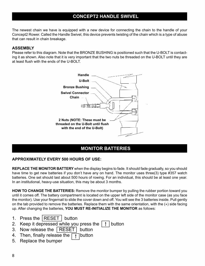
The newest chain we have is equipped with a new device for connecting the chain to the handle of your Concept2 Rower. Called the Handle Swivel, this device prevents twisting of the chain which is a type of abuse that can result in chain breakage.
ASSEMbLyPlease refer to this diagram. Note that the BRONZE BUSHING is positioned such that the U-BOLT is contact-ing it as shown. Also note that it is very important that the two nuts be threaded on the U-BOLT until they are at least flush with the ends of the U-BOLT.
2 Nuts (NOTE: These must be threaded on the U-Bolt until flush
with the end of the U-bolt)
HandleU-bolt
bronze bushingSwivel Connector
Chain
MONITOR bATTERIES
APPROXIMATELy EVERy 500 HOURS OF USE:
REPLACE THE MONITOR bATTERy when the display begins to fade. It should fade gradually, so you should have time to get new batteries if you don’t have any on hand. The monitor uses three(3) type #357 watch batteries. One set should last about 500 hours of rowing. For an individual, this should be at least one year. In an institutional, heavy-use situation, this may be about 3 months.
HOW TO CHANGE THE bATTERIES: Remove the monitor bumper by pulling the rubber portion toward you until it comes off. The battery compartment is located on the upper left side of the monitor case (as you face the monitor). Use your fingernail to slide the cover down and off. You will see the 3 batteries inside. Pull gently on the tab provided to remove the batteries. Replace them with the same orientation, with the (+) side facing up. After changing the batteries, yOU MUST RE-INITIALIZE THE MONITOR as follows:
1. Press the RESET button 2. Keep it depressed while you press the button 3. Now release the RESET button4. Then, finally release the button5. Replace the bumper
s
s
8
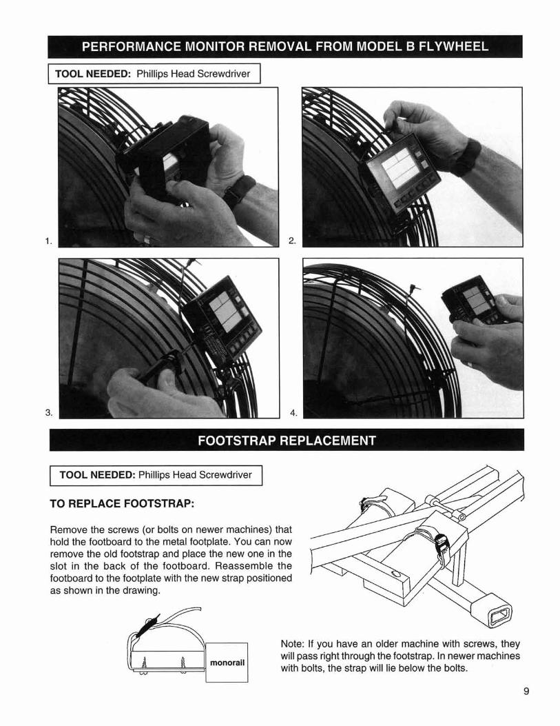
INSTALLING A NEW MONITOR PICKUP
Use Part #265
1. Remove the monitor bumper by pulling the rubber outer portion toward you until it comes off.
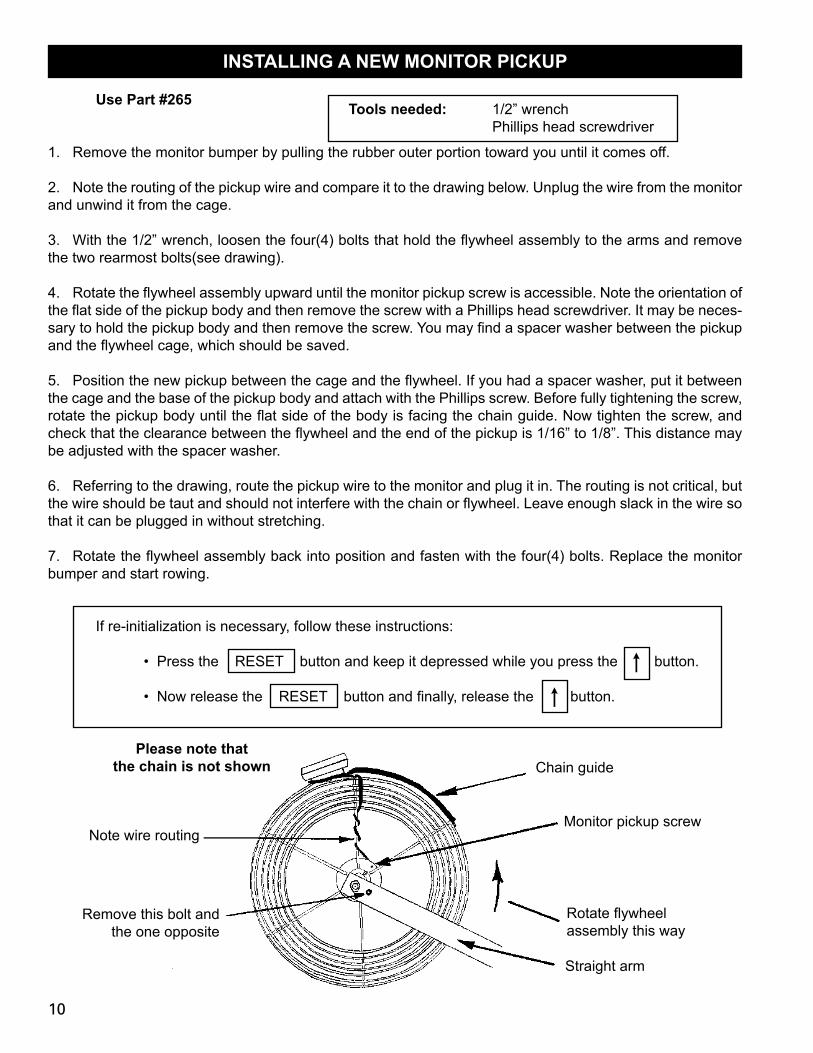
2. Note the routing of the pickup wire and compare it to the drawing below. Unplug the wire from the monitor and unwind it from the cage.
3. With the 1/2” wrench, loosen the four(4) bolts that hold the flywheel assembly to the arms and remove the two rearmost bolts(see drawing).
4. Rotate the flywheel assembly upward until the monitor pickup screw is accessible. Note the orientation of the flat side of the pickup body and then remove the screw with a Phillips head screwdriver. It may be neces-sary to hold the pickup body and then remove the screw. You may find a spacer washer between the pickup and the flywheel cage, which should be saved.
5. Position the new pickup between the cage and the flywheel. If you had a spacer washer, put it between the cage and the base of the pickup body and attach with the Phillips screw. Before fully tightening the screw, rotate the pickup body until the flat side of the body is facing the chain guide. Now tighten the screw, and check that the clearance between the flywheel and the end of the pickup is 1/16” to 1/8”. This distance may be adjusted with the spacer washer.
6. Referring to the drawing, route the pickup wire to the monitor and plug it in. The routing is not critical, but the wire should be taut and should not interfere with the chain or flywheel. Leave enough slack in the wire so that it can be plugged in without stretching.
7. Rotate the flywheel assembly back into position and fasten with the four(4) bolts. Replace the monitor bumper and start rowing.
If re-initialization is necessary, follow these instructions:
• Press the RESET button and keep it depressed while you press the button.
• Now release the RESET button and finally, release the button.
s
s
Note wire routing
Remove this bolt and the one opposite
Chain guide
Rotate flywheel assembly this way
Straight arm
Please note that the chain is not shown
Monitor pickup screw
Tools needed: 1/2” wrench Phillips head screwdriver
10
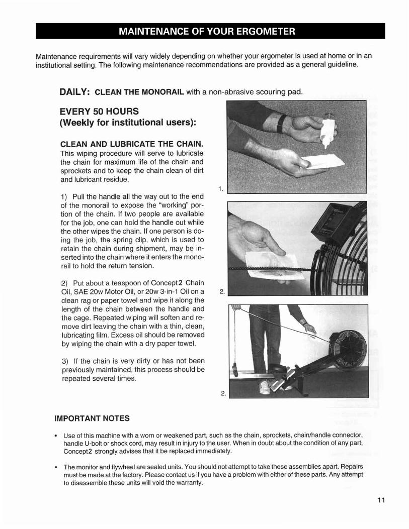
MAINTENANCE OF YOUR ERGOMETER
EVERy 250 HOURS OF USE (Monthly for Institutional Users):
1) INSPECT THE CHAIN FOR STIFF LINKS. Stiff links in the chain can cause the chain to skip over the sprocket creating a severe wear situation. We recommend a monthly inspection of the portion of the chain that contacts the sprockets. This should take about 5 minutes. Stiff links may be caused by a lack of lubrica-tion, or a build-up of dirt and old lubrication. In most cases, cleaning and lubrication will loosen up the links. If it does not, the chain should be replaced. If the chain skips on the sprocket, the ergometer should not be used and Concept2 should be contacted.
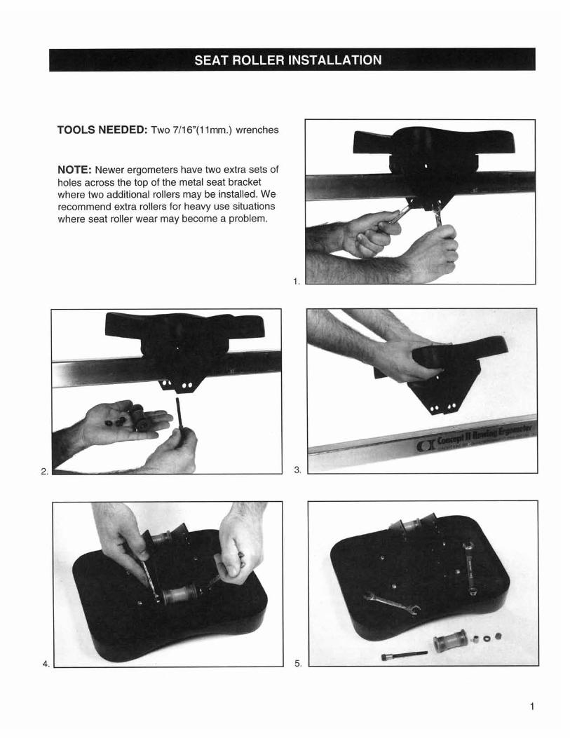
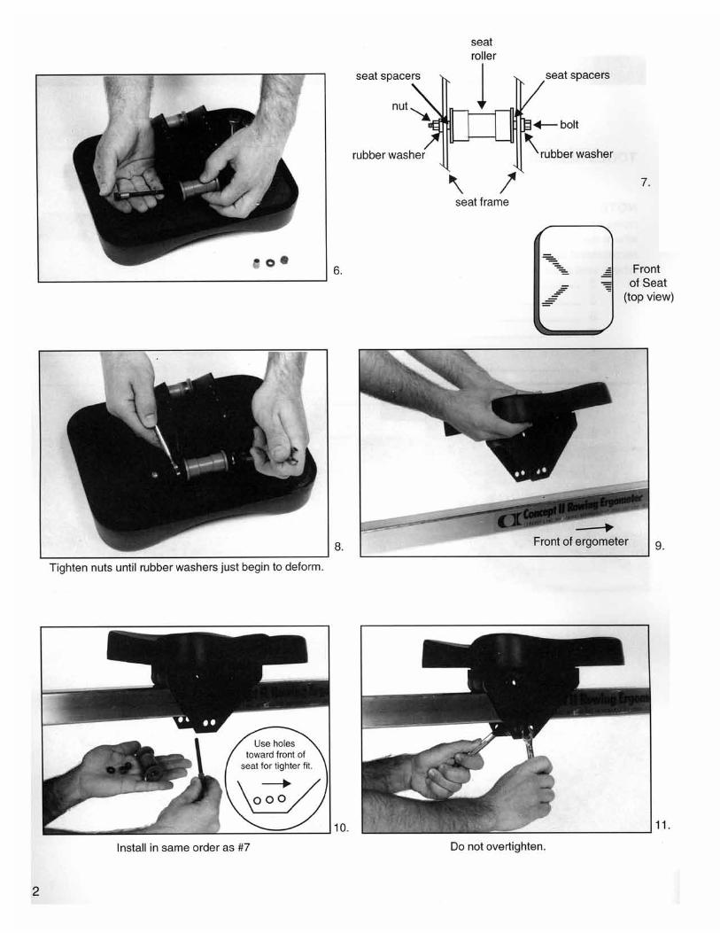
2) ADJUST THE bOTTOM SEAT ROLLER if the seat seems to be too loose on the monorail. Loosen the nut and bolt holding the bottom roller in place, remove the roller, and move it to the next tighter set of holes in the seat carriage. Reassemble and tighten nut lightly.
3) INSPECT THE CHAIN HANDLE CONNECTION. Specifically look closely at the hole in the connec-tor piece through which the U-bolt passes. This hole will tend to elongate with wear. If the hole is over 7/16” long, or if the U-bolt itself is nearly half worn through, the whole chain and connectors should be replaced. Before you order these parts, we recommend that you remove the skewer from the monorail following the instructions on page 3 and check for any other worn out parts such as the shock cord, travelling pulley, chain slide, and white plastic pulleys. You may wish to order a complete new skewer assembly if several parts are worn. It will make installation of the new chain much easier.
4) TIGHTEN THE SHOCK CORD if the handle does not return all the way against chain guide. To tighten the shock cord, pull the S.C.A.M. (see skewer detail drawing on page 3) out the back of the monorail with a pair of pliers and feed enough cord through the S.C.A.M. to achieve the desired tension. If you have more than 6” of excess cord, it should be trimmed after taping the area to be cut to prevent unraveling.
5) CHECK TO bE SURE THAT THE FOLLOWING NUTS AND bOLTS ARE NOT LOOSE: • Two 1/4” nylon insert nuts at handle • Four 5/16” bolts holding flywheel to frame • Four 5/16” nuts holding legs to monorail • Four 3/8” nuts holding arms and footboards to monorail
APPROXIMATELy EVERy 500 HOURS OF USE:
REPLACE THE MONITOR bATTERIES following directions on page 8.
STORAGE SUGGESTION:It is best to let the oar handle rest against the fan cage rather than in the handle hook when the machine is not in constant use (i.e. overnight, between workouts). This will prolong the life of the shock cord.
12
TROUbLESHOOTING
SyMPTOM: Scraping noise in the monorailPOSSIbLE CAUSE: Skewer not properly positioned in monorailREMEDy: Loosen the four(4) screws holding the skewer in the monorail, then retighten starting with the front right side (as you sit on seat facing the wheel), followed by the right rear, then the left front, and finally the left rear. If this doesn’t help, shine a flashlight in one end of the monorail while looking through the other end, and have someone row very slowly. Check for any interference of moving parts which might be causing the noise. Next, try pulling out the skewer. Compare it to the skewer drawing on page 3 (Fig.A), being sure that there aren’t any twists in either the chain or the shock cord. If you still haven’t found anything wrong and the noise persists, try bending the skewer very slightly away from the travelling pulley. When you put it back in the monorail, be sure to position it as described above. If the noise still persists, contact Concept2 for further help.
SyMPTOM: Tinkling/clinking sound in the monorailPOSSIbLE CAUSE: Shock cord too looseREMEDy: Tighten shock cord as described in the maintenance section
SyMPTOM: Seat sticks on monorailPOSSIbLE CAUSE: The monorail may not be clean. Or the bottom seat roller may be installed such that the seat fits too tightly on the monorail.REMEDy: Clean the monorail. Rollers often wear rapidly at first until they conform to the shape of the monorail. If this is the case, your seat may feel tight and your monorail may need more frequent cleaning until this wearing process is complete. If the seat is still very tight on the monorail, the bottom seat roller will need adjustment. See page 1.
SyMPTOM: Seat is wobblyPOSSIbLE CAUSE: The seat rollers may need adjustment.REMEDy: Adjust seat rollers as described on page 1.
SyMPTOM: Chain skips on sprocket during the drive or runs roughly on sprocket during the recovery.POSSIbLE CAUSE: Stiff links in chain.REMEDy: Clean and lubricate the chain. If it continues to skip, the machine should not be rowed and you should contact Concept II immediately.
SyMPTOM: Handle does not retract all the way to the cage and hangs loose.POSSIbLE CAUSE: Shock cord too loose due to normal stretching or cold temperatures.REMEDy: Adjust shock cord tension as described in maintenance section. Replace if frayed through outer cover or losing its elasticity. If it is cold, allow it to warm up.
SyMPTOM: Monitor display fails to come on when you start to rowPOSSIbLE CAUSES & REMEDIES: If you just changed the batteries, the polarity may be wrong. Try reversing the orientation of the batteries. If you have not just changed the batteries, try pressing the RESET button. If there is still no life in the display, you could try new batteries. If this doesn’t help, contact Concept2. If the RESET button does activate the display (with zeroes), there may be a problem with the monitor pickup. Again, you should contact Concept2.
SyMPTOM: Dimming of monitor displayPOSSIbLE CAUSE: Monitor not initialized, either because battery was just changed, or monitor became uninitialized during shipping.REMEDy: Initialize monitor as follows: Press RESET button and keep it depressed while you press the button. Now release RESET and finally release button. rr
13
Recommended