NetComm GAteWAy™ SerieSADSL2+ Wireless N150 Modem Router
USER GUIDE
ADSL2+ Wireless N150 Modem Router User Guide YML14WN2 www.netcomm.com.au
PrefaceThis manual provides information related to the installation, operation, and application of this device. The individual reading this manual is presumed to have a basic understanding of telecommunications terminology and concepts.
If you find the product to be broken or malfunctioning, please contact technical support for immediate service by email at [email protected]
For product update, new product release, manual revision, or software upgrades, please visit our website at www.netcommlimited.com
Important Safety InstructionsWith reference to unpacking, installation, use and maintenance of your electronic device, the following basic guidelines are recommended:
• Do not use or install this product near water, to avoid fire or shock hazard. For example, near a bathtub, kitchen sink or laundry tub, or near a swimming pool. Also, do not expose the equipment to rain or damp areas (e.g. a wet basement).
• Do not connect the power supply cord on elevated surfaces. Allow it to lie freely. There should be no obstructions in its path and no heavy items should be placed on the cord. In addition, do not walk on, step on or mistreat the cord.
• Use only the power cord and adapter that are shipped with this device.
• To safeguard the equipment against overheating, make sure that all openings in the unit that offer exposure to air are not blocked.
• Avoid using a telephone (other than a cordless type) during an electrical storm. There may be a remote risk of electric shock from lightening. Also, do not use the telephone to report a gas leak in the vicinity of the leak.
• Never install telephone wiring during stormy weather conditions.
WARNING
• Disconnect the power line from the device before servicing.
Copyright
Copyright©2010 NetComm Limited. All rights reserved. The information contained herein is proprietary to NetComm Limited. No part of this document may be translated, transcribed, reproduced, in any form, or by any means without prior written consent of NetComm LimitedNOTE:This document is subject to change without notice.
Save Our EnvironmentWhen this equipment has reached the end of its useful life, it must be taken to a recycling centre and processed separate from domestic waste.The cardboard box, the plastic contained in the packaging, and the parts that make up this router can be recycled in accordance with regionally established regulations. Never dispose of this electronic equipment along with your household waste. You may be subject to penalties or sanctions under the law. Instead, ask for disposal instructions from your municipal government.
Please be responsible and protect our environment.
YML14WN ADSL2+ Wireless N150 Modem Router User Guidewww.netcomm.com.au 3
NetComm Gateway Series - ADSL2+ Wireless N150 Modem Router
Table of ContentsIntroduction ...............................................................................................................................................................................................4
Features ...........................................................................................................................................................................................................................5Application .......................................................................................................................................................................................................................5LED Indicators..................................................................................................................................................................................................................5Back Panel Connectors ....................................................................................................................................................................................................6Factory Default Settings ...................................................................................................................................................................................................7Hardware Requirements ...................................................................................................................................................................................................7System Requirements ......................................................................................................................................................................................................7Package Contents............................................................................................................................................................................................................7
Installation & Setup ...................................................................................................................................................................................8
ADSL2+ Wireless N150 Modem Router Configuration ..........................................................................................................................14
Web User Interface ..................................................................................................................................................................................17Web Configuration Overview ..........................................................................................................................................................................................18Accessing the ADSL2+ Wireless N150 Modem Router Web User Interface ....................................................................................................................18
Quick Start ...............................................................................................................................................................................................19
Interface Setup ........................................................................................................................................................................................22Internet ..........................................................................................................................................................................................................................23LAN ...............................................................................................................................................................................................................................24Wireless .........................................................................................................................................................................................................................25Wireless Security ............................................................................................................................................................................................................26WPS Settings .................................................................................................................................................................................................................26
Advanced Setup ......................................................................................................................................................................................27Firewall ...........................................................................................................................................................................................................................28Routing ..........................................................................................................................................................................................................................28QoS ...............................................................................................................................................................................................................................30VLAN .............................................................................................................................................................................................................................31ADSL .............................................................................................................................................................................................................................32
Access Management ..............................................................................................................................................................................33ACL Settings ..................................................................................................................................................................................................................34Filtering ..........................................................................................................................................................................................................................34Universal Plug-and-Play (UPnP) ......................................................................................................................................................................................36DDNS ............................................................................................................................................................................................................................37CWMP ...........................................................................................................................................................................................................................37
Maintenance ............................................................................................................................................................................................40Admin Setting ................................................................................................................................................................................................................40System Time ..................................................................................................................................................................................................................40Firmware Update ............................................................................................................................................................................................................41System Reset .................................................................................................................................................................................................................41Diagnostics ....................................................................................................................................................................................................................41
Status .......................................................................................................................................................................................................43Device Info .....................................................................................................................................................................................................................43System Log ....................................................................................................................................................................................................................44Statistics ........................................................................................................................................................................................................................44
Appendix A: Installing UPnP in Windows Example ...............................................................................................................................46Installing UPnP in Windows Me ......................................................................................................................................................................................46Installing UPnP in Windows XP .......................................................................................................................................................................................47Using UPnP in Windows XP Example .............................................................................................................................................................................48Auto-discover Your UPnP-enabled Network Device ........................................................................................................................................................48Web Configuration Easy Access .....................................................................................................................................................................................50
Appendix B: Troubleshooting .................................................................................................................................................................52
Appendix C: Technology Glossary .........................................................................................................................................................55
Appendix D: Legal and Regulatory Information .....................................................................................................................................58Customer Information .....................................................................................................................................................................................................58Federal Communication Comission Interference statement ............................................................................................................................................59Product Warranty ...........................................................................................................................................................................................................59Limitations of Warranty ...................................................................................................................................................................................................60

Introduction
YML14WN ADSL2+ Wireless N150 Modem Router User Guidewww.netcomm.com.au 5
NetComm Gateway Series - ADSL2+ Wireless N150 Modem Router
IntroductionThe NetComm NB14WN ADSL2+ Wireless N150 Modem Router allows you to connect to a broadband Internet service and share the connection with multiple users. Also including a host of other features that exist to make your experience as seamless as possible, the NB14WN is an ideal entry level Wireless N ADSL2+ product.
With a built-in Wireless N access point providing speeds of up to 150Mbps, multiple users are able to connect any Internet enabled device to the NB14WN without wires and access the Internet from a location convenient to them. On top of this, the NB14WN also comes with a built-in 4 port Ethernet switch, allowing for other devices to access the Internet over a wired connection.
The NB14WN also has a number of handy features that assist in delivering you the best possible user experience. These include a WPS push button that allows for an easy set-up of your wireless network, a push button to easily turn your wireless signal on and off, advanced security options to ensure your network remains safe and an easy to navigate web interface if you need to change any settings.
Features• Fully featured ADSL2+ modem router
• Wireless N access point for speeds of up to 150Mbps
• 4 LAN ports for multiple wired connections
• WPS button for simple set up of your wireless network
• Advanced wireless security to maintain the integrity of your network
• Easy to use web based setup and configuration
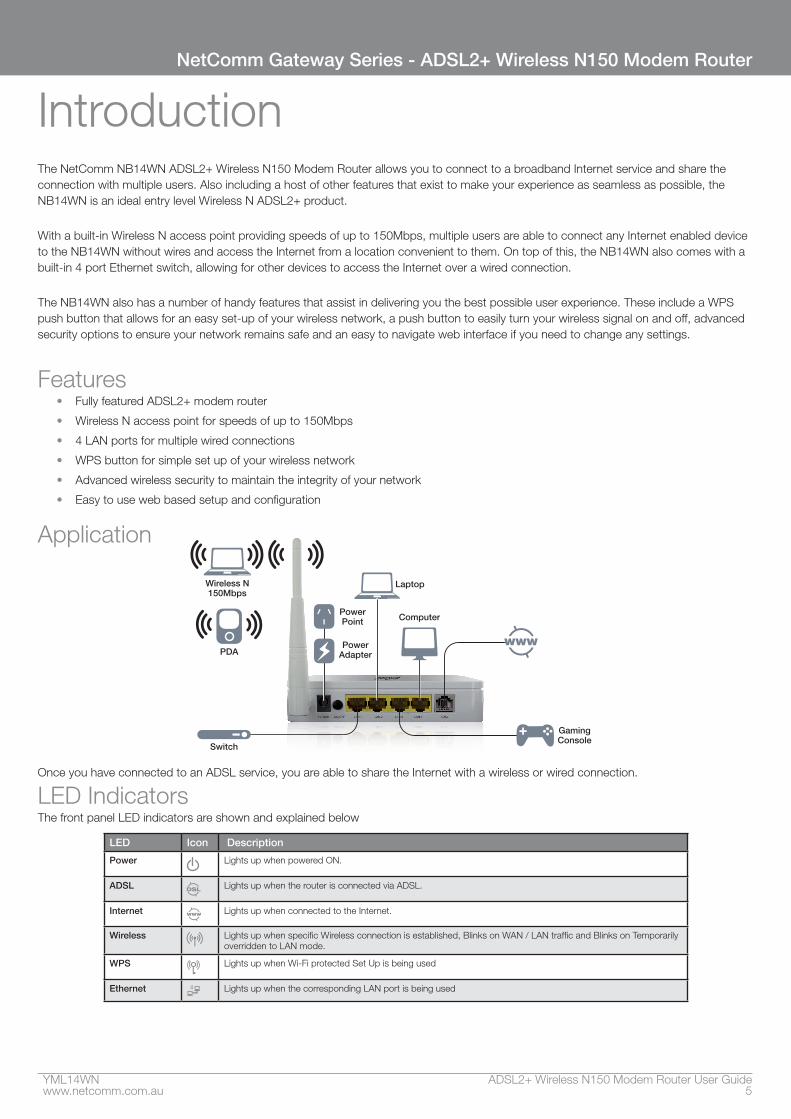
Application
Wireless N150Mbps
PDA
GamingConsole
Computer
Laptop
Switch
PowerPoint
PowerAdapter
Once you have connected to an ADSL service, you are able to share the Internet with a wireless or wired connection.
LED IndicatorsThe front panel LED indicators are shown and explained below
LED Icon Description
Power Lights up when powered ON.
ADSL Lights up when the router is connected via ADSL.
Internet Lights up when connected to the Internet.
Wireless Lights up when specific Wireless connection is established, Blinks on WAN / LAN traffic and Blinks on Temporarily overridden to LAN mode.
WPS Lights up when Wi-Fi protected Set Up is being used
Ethernet Lights up when the corresponding LAN port is being used
ADSL2+ Wireless N150 Modem Router User Guide YML14WN6 www.netcomm.com.au
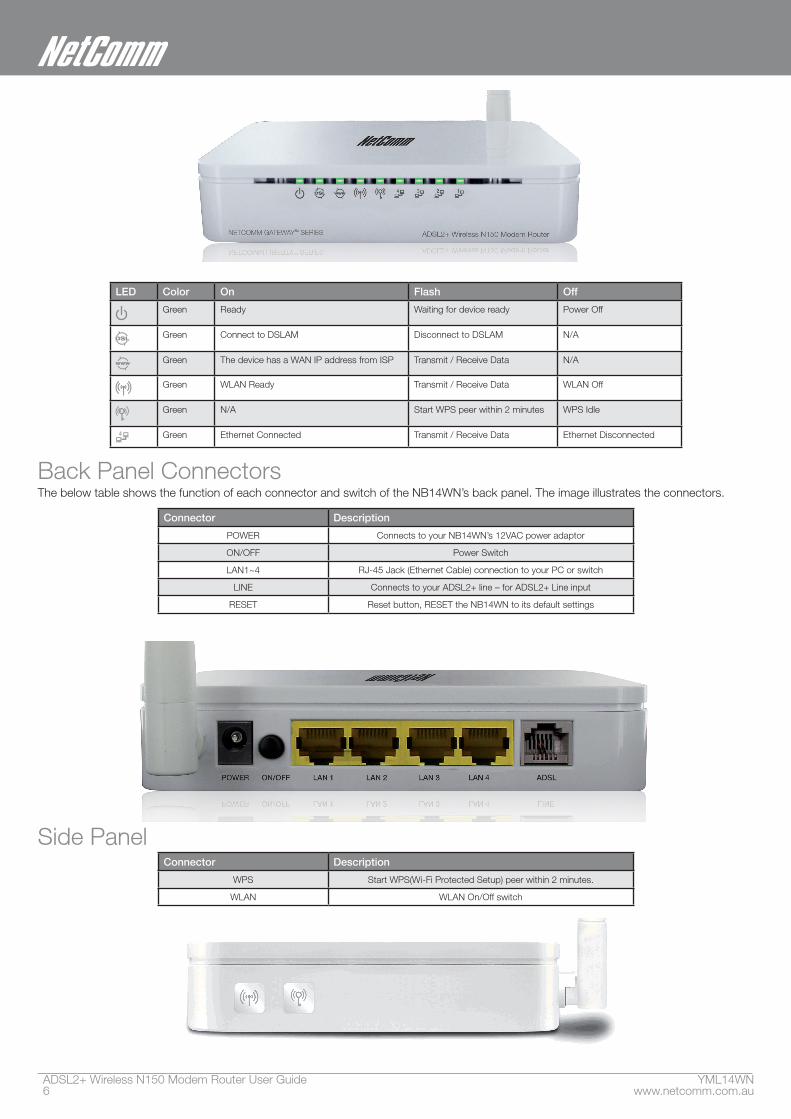
LED Color On Flash Off
Green Ready Waiting for device ready Power Off
Green Connect to DSLAM Disconnect to DSLAM N/A
Green The device has a WAN IP address from ISP Transmit / Receive Data N/A
Green WLAN Ready Transmit / Receive Data WLAN Off
Green N/A Start WPS peer within 2 minutes WPS Idle
Green Ethernet Connected Transmit / Receive Data Ethernet Disconnected
Back Panel ConnectorsThe below table shows the function of each connector and switch of the NB14WN’s back panel. The image illustrates the connectors.
Connector Description
POWER Connects to your NB14WN’s 12VAC power adaptor
ON/OFF Power Switch
LAN1~4 RJ-45 Jack (Ethernet Cable) connection to your PC or switch
LINE Connects to your ADSL2+ line – for ADSL2+ Line input
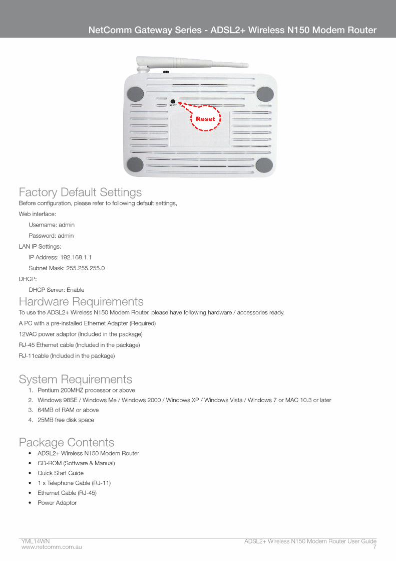
RESET Reset button, RESET the NB14WN to its default settings
Side PanelConnector Description
WPS Start WPS(Wi-Fi Protected Setup) peer within 2 minutes.
WLAN WLAN On/Off switch
YML14WN ADSL2+ Wireless N150 Modem Router User Guidewww.netcomm.com.au 7
NetComm Gateway Series - ADSL2+ Wireless N150 Modem Router
Factory Default SettingsBefore configuration, please refer to following default settings,
Web interface:
Username: admin
Password: admin
LAN IP Settings:
IP Address: 192.168.1.1
Subnet Mask: 255.255.255.0
DHCP:
DHCP Server: Enable
Hardware RequirementsTo use the ADSL2+ Wireless N150 Modem Router, please have following hardware / accessories ready.
A PC with a pre-installed Ethernet Adapter (Required)
12VAC power adaptor (Included in the package)
RJ-45 Ethernet cable (Included in the package)
RJ-11cable (Included in the package)
System Requirements1. Pentium 200MHZ processor or above
2. Windows 98SE / Windows Me / Windows 2000 / Windows XP / Windows Vista / Windows 7 or MAC 10.3 or later
3. 64MB of RAM or above
4. 25MB free disk space
Package Contents • ADSL2+ Wireless N150 Modem Router
• CD-ROM (Software & Manual)
• Quick Start Guide
• 1 x Telephone Cable (RJ-11)
• Ethernet Cable (RJ-45)
• Power Adaptor
Installation and SetUp
YML14WN ADSL2+ Wireless N150 Modem Router User Guidewww.netcomm.com.au 9
NetComm Gateway Series - ADSL2+ Wireless N150 Modem Router
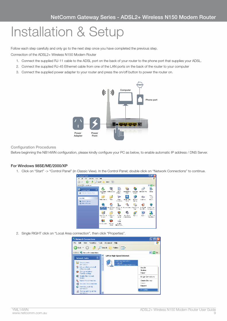
Installation & SetupFollow each step carefully and only go to the next step once you have completed the previous step.
Connection of the ADSL2+ Wireless N150 Modem Router
1. Connect the supplied RJ-11 cable to the ADSL port on the back of your router to the phone port that supplies your ADSL.
2. Connect the supplied RJ-45 Ethernet cable from one of the LAN ports on the back of the router to your computer
3. Connect the supplied power adapter to your router and press the on/off button to power the router on.
Computer
Phone port
PowerPoint
Power Adapter
Configuration ProceduresBefore beginning the NB14WN configuration, please kindly configure your PC as below, to enable automatic IP address / DNS Server.
For Windows 98SE/ME/2000/XP1. Click on “Start” -> “Control Panel” (in Classic View). In the Control Panel; double click on “Network Connections” to continue.
2. Single RIGHT click on “Local Area connection”, then click “Properties”.
ADSL2+ Wireless N150 Modem Router User Guide YML14WN10 www.netcomm.com.au
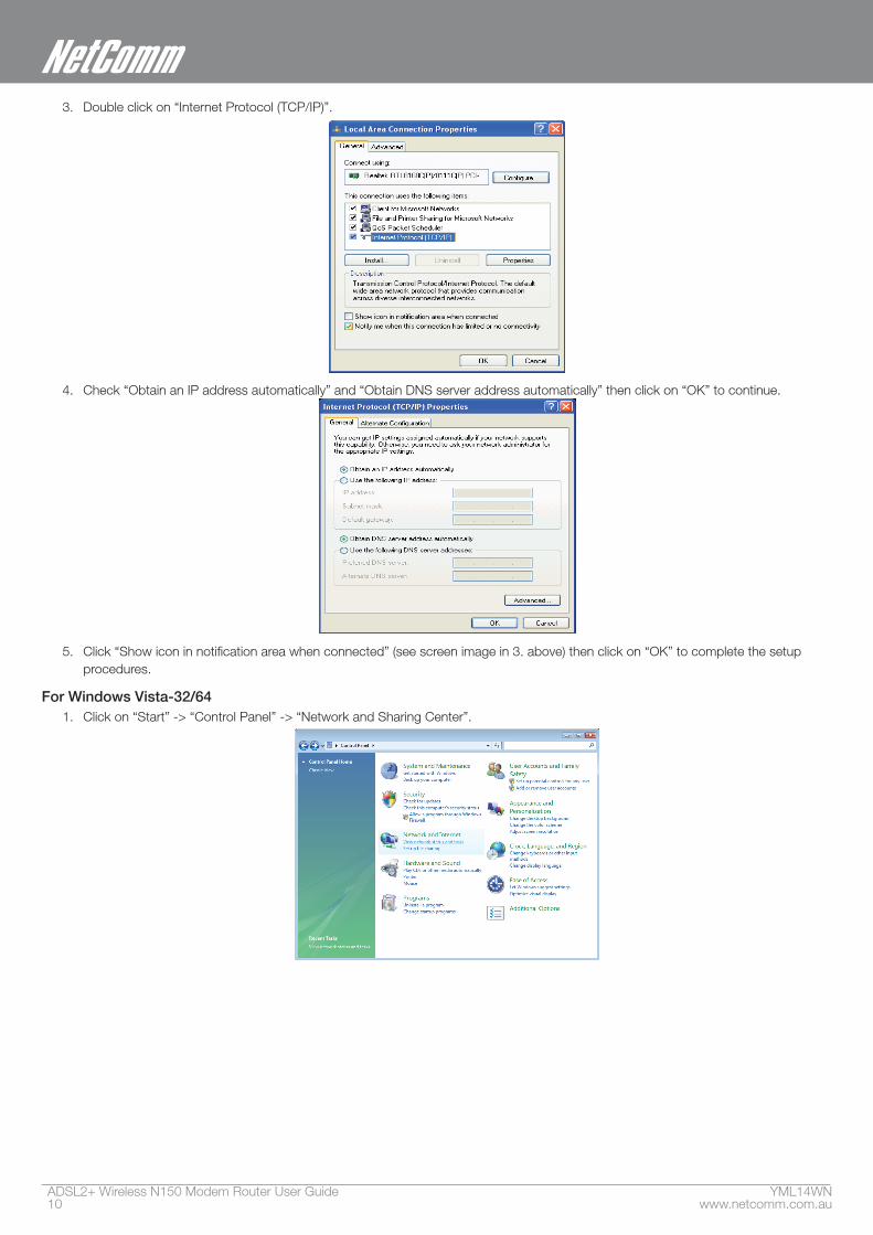
3. Double click on “Internet Protocol (TCP/IP)”.
4. Check “Obtain an IP address automatically” and “Obtain DNS server address automatically” then click on “OK” to continue.
5. Click “Show icon in notification area when connected” (see screen image in 3. above) then click on “OK” to complete the setup procedures.
For Windows Vista-32/641. Click on “Start” -> “Control Panel” -> “Network and Sharing Center”.
YML14WN ADSL2+ Wireless N150 Modem Router User Guidewww.netcomm.com.au 11
NetComm Gateway Series - ADSL2+ Wireless N150 Modem Router
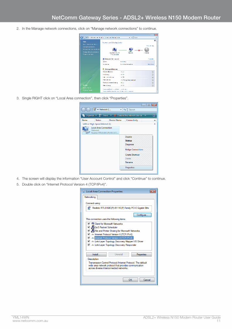
2. In the Manage network connections, click on “Manage network connections” to continue.
3. Single RIGHT click on “Local Area connection”, then click “Properties”.
4. The screen will display the information “User Account Control” and click “Continue” to continue.
5. Double click on “Internet Protocol Version 4 (TCP/IPv4)”.
ADSL2+ Wireless N150 Modem Router User Guide YML14WN12 www.netcomm.com.au
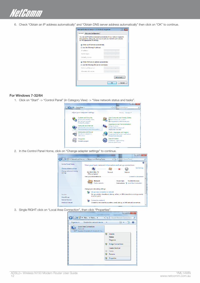
6. Check “Obtain an IP address automatically” and “Obtain DNS server address automatically” then click on “OK” to continue.
For Windows 7-32/641. Click on “Start” -> “Control Panel” (in Category View) -> “View network status and tasks”.
2. In the Control Panel Home, click on “Change adapter settings” to continue.
3. Single RIGHT click on “Local Area Connection”, then click “Properties”.
YML14WN ADSL2+ Wireless N150 Modem Router User Guidewww.netcomm.com.au 13
NetComm Gateway Series - ADSL2+ Wireless N150 Modem Router
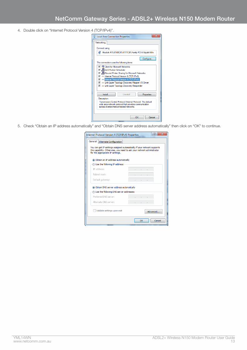
4. Double click on “Internet Protocol Version 4 (TCP/IPv4)”.
5. Check “Obtain an IP address automatically” and “Obtain DNS server address automatically” then click on “OK” to continue.
ADSL2+ Wireless N150 Modem Router Configuration
YML14WN ADSL2+ Wireless N150 Modem Router User Guidewww.netcomm.com.au 15
NetComm Gateway Series - ADSL2+ Wireless N150 Modem Router
ADSL2+ Wireless N150 Modem Router Configuration
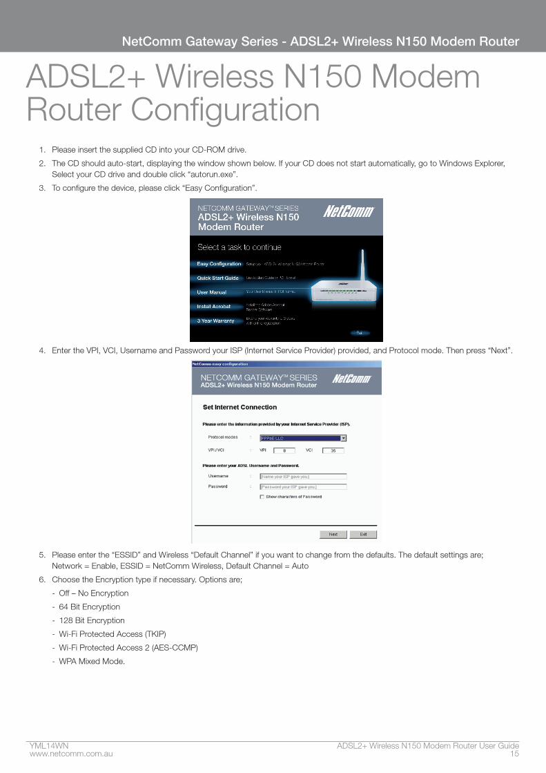
1. Please insert the supplied CD into your CD-ROM drive.
2. The CD should auto-start, displaying the window shown below. If your CD does not start automatically, go to Windows Explorer, Select your CD drive and double click “autorun.exe”.
3. To configure the device, please click “Easy Configuration”.
4. Enter the VPI, VCI, Username and Password your ISP (Internet Service Provider) provided, and Protocol mode. Then press “Next”.
5. Please enter the “ESSID” and Wireless “Default Channel” if you want to change from the defaults. The default settings are; Network = Enable, ESSID = NetComm Wireless, Default Channel = Auto
6. Choose the Encryption type if necessary. Options are;
- Off – No Encryption
- 64 Bit Encryption
- 128 Bit Encryption
- Wi-Fi Protected Access (TKIP)
- Wi-Fi Protected Access 2 (AES-CCMP)
- WPA Mixed Mode.
ADSL2+ Wireless N150 Modem Router User Guide YML14WN16 www.netcomm.com.au
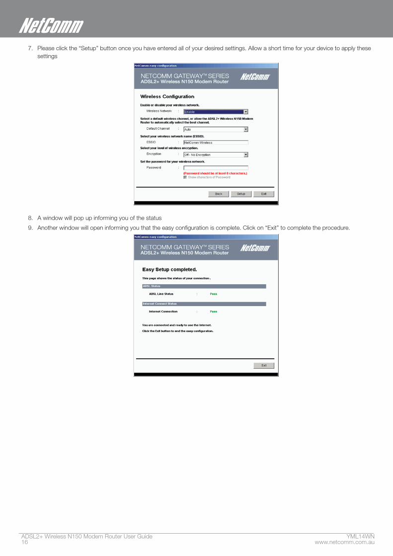
7. Please click the “Setup” button once you have entered all of your desired settings. Allow a short time for your device to apply these settings
8. A window will pop up informing you of the status
9. Another window will open informing you that the easy configuration is complete. Click on “Exit” to complete the procedure.

Web User Interface
ADSL2+ Wireless N150 Modem Router User Guide YML14WN18 www.netcomm.com.au
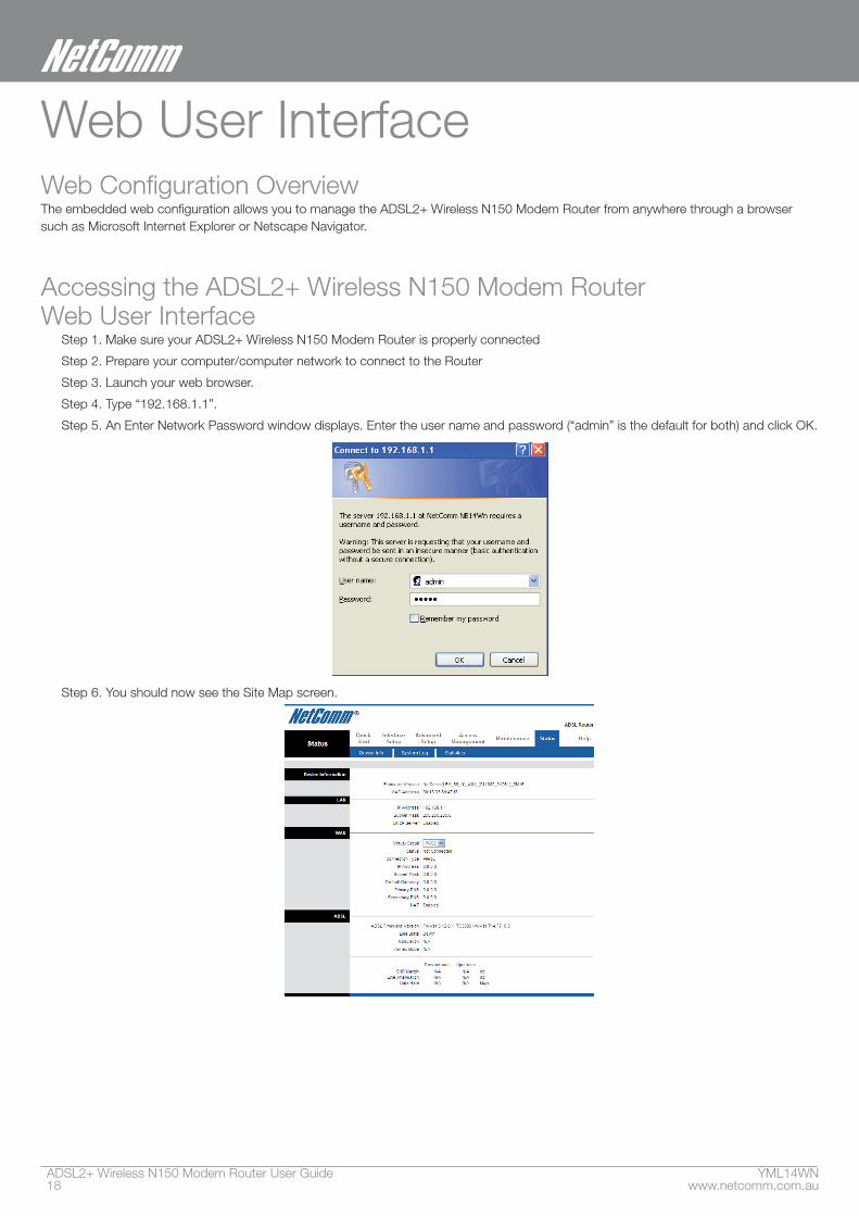
Web User InterfaceWeb Configuration OverviewThe embedded web configuration allows you to manage the ADSL2+ Wireless N150 Modem Router from anywhere through a browser such as Microsoft Internet Explorer or Netscape Navigator.
Accessing the ADSL2+ Wireless N150 Modem Router Web User Interface
Step 1. Make sure your ADSL2+ Wireless N150 Modem Router is properly connected
Step 2. Prepare your computer/computer network to connect to the Router
Step 3. Launch your web browser.
Step 4. Type “192.168.1.1”.
Step 5. An Enter Network Password window displays. Enter the user name and password (“admin” is the default for both) and click OK.
Step 6. You should now see the Site Map screen.

Quick Start
ADSL2+ Wireless N150 Modem Router User Guide YML14WN20 www.netcomm.com.au
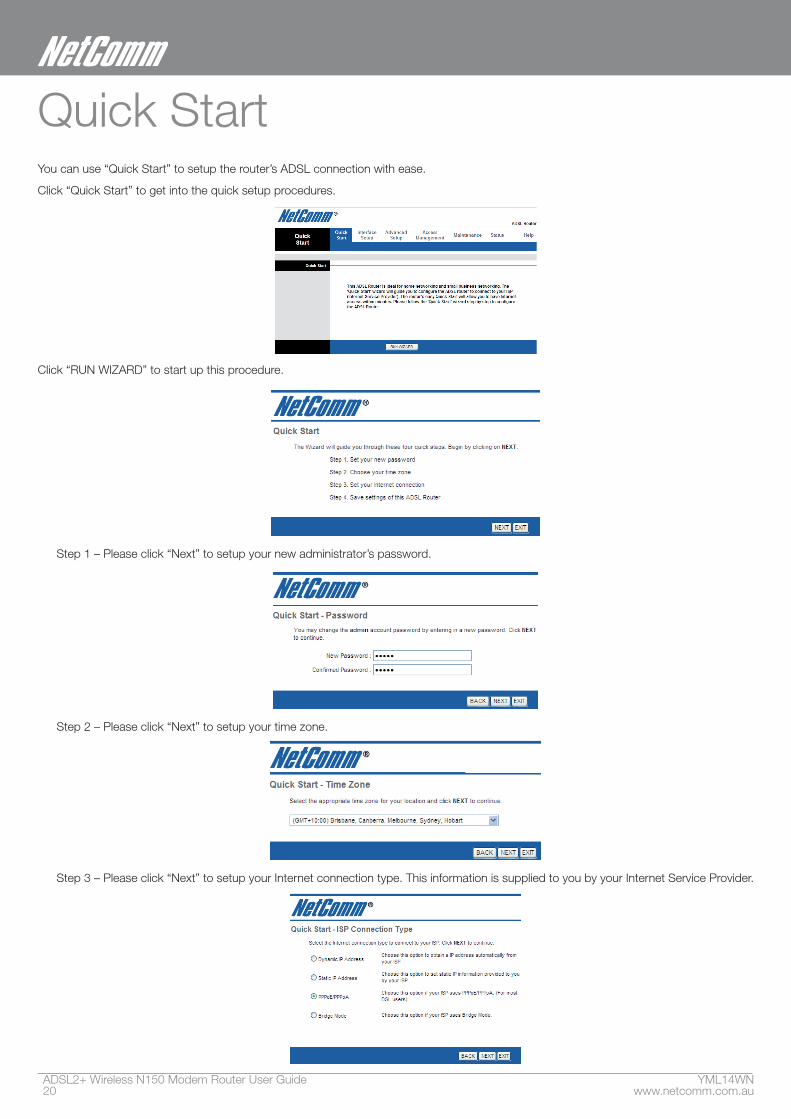
Quick StartYou can use “Quick Start” to setup the router’s ADSL connection with ease.
Click “Quick Start” to get into the quick setup procedures.
Click “RUN WIZARD” to start up this procedure.
Step 1 – Please click “Next” to setup your new administrator’s password.
Step 2 – Please click “Next” to setup your time zone.
Step 3 – Please click “Next” to setup your Internet connection type. This information is supplied to you by your Internet Service Provider.
YML14WN ADSL2+ Wireless N150 Modem Router User Guidewww.netcomm.com.au 21
NetComm Gateway Series - ADSL2+ Wireless N150 Modem Router
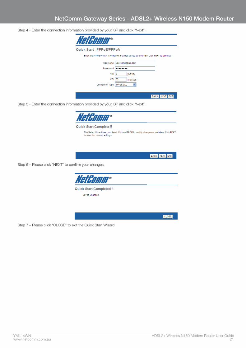
Step 4 - Enter the connection information provided by your ISP and click “Next”.
Step 5 - Enter the connection information provided by your ISP and click “Next”.
Step 6 – Please click “NEXT” to confirm your changes.
Step 7 – Please click “CLOSE” to exit the Quick Start Wizard
Interface Setup
YML14WN ADSL2+ Wireless N150 Modem Router User Guidewww.netcomm.com.au 23
NetComm Gateway Series - ADSL2+ Wireless N150 Modem Router
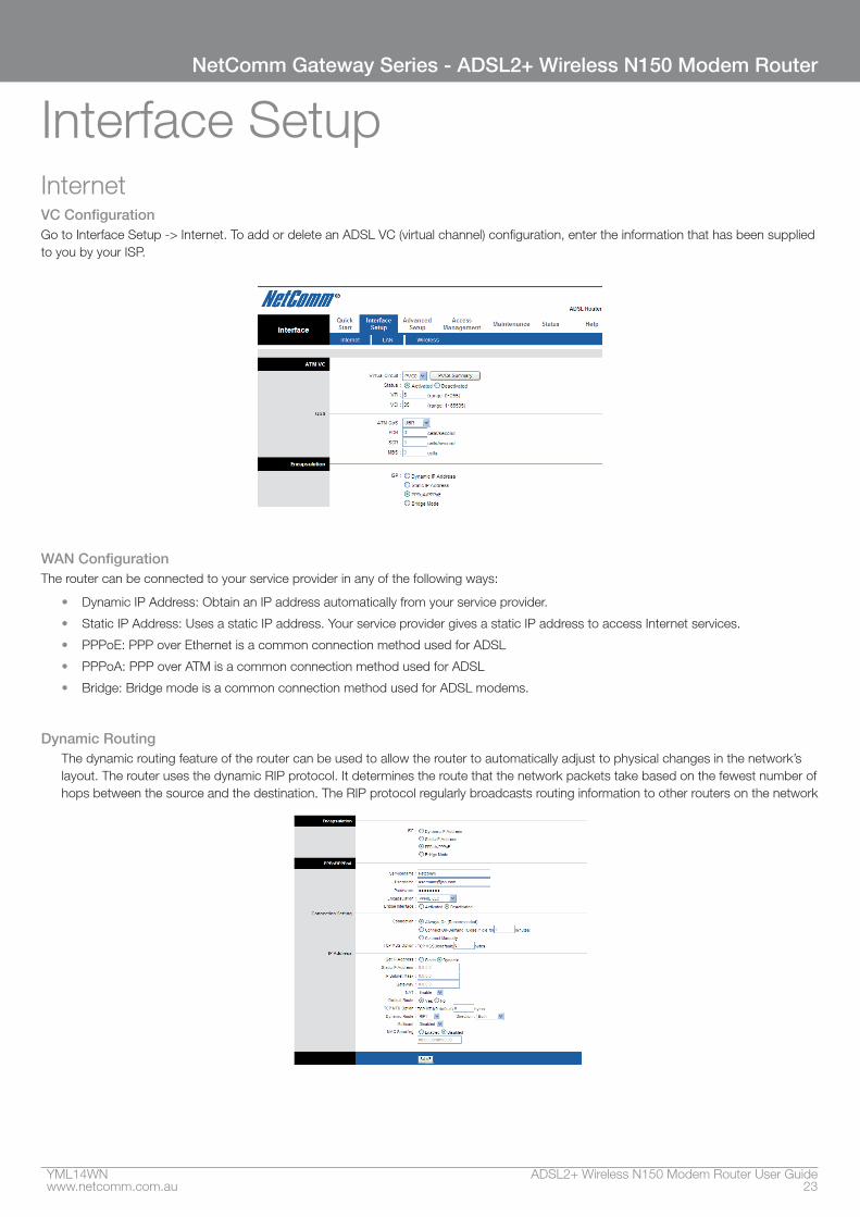
Interface SetupInternet VC Configuration Go to Interface Setup -> Internet. To add or delete an ADSL VC (virtual channel) configuration, enter the information that has been supplied to you by your ISP.
WAN ConfigurationThe router can be connected to your service provider in any of the following ways:
• Dynamic IP Address: Obtain an IP address automatically from your service provider.
• Static IP Address: Uses a static IP address. Your service provider gives a static IP address to access Internet services.
• PPPoE: PPP over Ethernet is a common connection method used for ADSL
• PPPoA: PPP over ATM is a common connection method used for ADSL
• Bridge: Bridge mode is a common connection method used for ADSL modems.
Dynamic RoutingThe dynamic routing feature of the router can be used to allow the router to automatically adjust to physical changes in the network’s layout. The router uses the dynamic RIP protocol. It determines the route that the network packets take based on the fewest number of hops between the source and the destination. The RIP protocol regularly broadcasts routing information to other routers on the network
ADSL2+ Wireless N150 Modem Router User Guide YML14WN24 www.netcomm.com.au
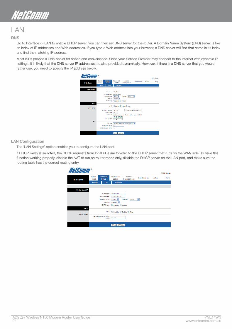
LANDNS
Go to Interface -> LAN to enable DHCP server. You can then set DNS server for the router. A Domain Name System (DNS) server is like an index of IP addresses and Web addresses. If you type a Web address into your browser, a DNS server will find that name in its index and find the matching IP address.
Most ISPs provide a DNS server for speed and convenience. Since your Service Provider may connect to the Internet with dynamic IP settings, it is likely that the DNS server IP addresses are also provided dynamically. However, if there is a DNS server that you would rather use, you need to specify the IP address below.
LAN Configuration The ‘LAN Settings’ option enables you to configure the LAN port.
If DHCP Relay is selected, the DHCP requests from local PCs are forward to the DHCP server that runs on the WAN side. To have this function working properly, disable the NAT to run on router mode only, disable the DHCP server on the LAN port, and make sure the routing table has the correct routing entry.
YML14WN ADSL2+ Wireless N150 Modem Router User Guidewww.netcomm.com.au 25
NetComm Gateway Series - ADSL2+ Wireless N150 Modem Router
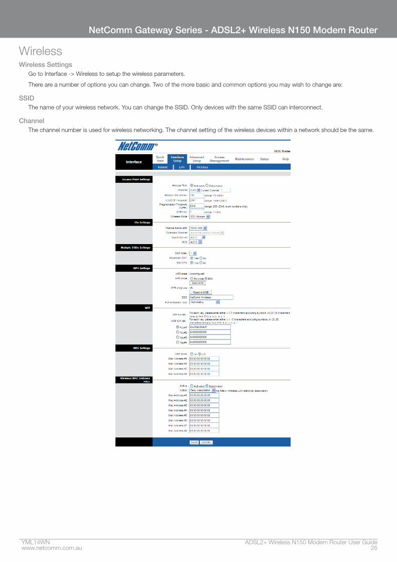
WirelessWireless Settings
Go to Interface -> Wireless to setup the wireless parameters.
There are a number of options you can change. Two of the more basic and common options you may wish to change are:
SSIDThe name of your wireless network. You can change the SSID. Only devices with the same SSID can interconnect.
ChannelThe channel number is used for wireless networking. The channel setting of the wireless devices within a network should be the same.
ADSL2+ Wireless N150 Modem Router User Guide YML14WN26 www.netcomm.com.au
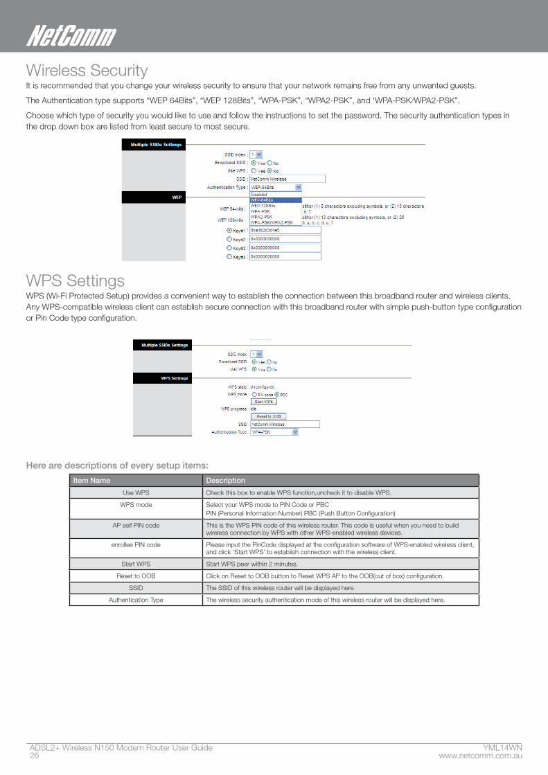
Wireless SecurityIt is recommended that you change your wireless security to ensure that your network remains free from any unwanted guests.
The Authentication type supports “WEP 64Bits”, “WEP 128Bits”, “WPA-PSK”, “WPA2-PSK”, and ‘WPA-PSK/WPA2-PSK”.
Choose which type of security you would like to use and follow the instructions to set the password. The security authentication types in the drop down box are listed from least secure to most secure.
WPS SettingsWPS (Wi-Fi Protected Setup) provides a convenient way to establish the connection between this broadband router and wireless clients. Any WPS-compatible wireless client can establish secure connection with this broadband router with simple push-button type configuration or Pin Code type configuration.
Here are descriptions of every setup items:
Item Name Description
Use WPS Check this box to enable WPS function,uncheck it to disable WPS.
WPS mode Select your WPS mode to PIN Code or PBCPIN (Personal Information Number) PBC (Push Button Configuration)
AP self PIN code This is the WPS PIN code of this wireless router. This code is useful when you need to build wireless connection by WPS with other WPS-enabled wireless devices.
enrollee PIN code Please input the PinCode displayed at the configuration software of WPS-enabled wireless client, and click ‘Start WPS’ to establish connection with the wireless client.
Start WPS Start WPS peer within 2 minutes.
Reset to OOB Click on Reset to OOB button to Reset WPS AP to the OOB(out of box) configuration.
SSID The SSID of this wireless router will be displayed here.
Authentication Type The wireless security authentication mode of this wireless router will be displayed here.

Advanced Setup
ADSL2+ Wireless N150 Modem Router User Guide YML14WN28 www.netcomm.com.au
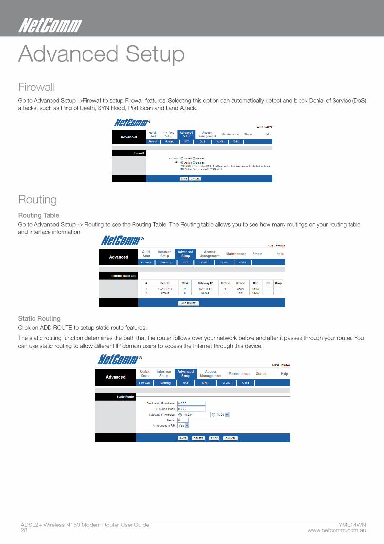
Advanced SetupFirewallGo to Advanced Setup ->Firewall to setup Firewall features. Selecting this option can automatically detect and block Denial of Service (DoS) attacks, such as Ping of Death, SYN Flood, Port Scan and Land Attack.
RoutingRouting TableGo to Advanced Setup -> Routing to see the Routing Table. The Routing table allows you to see how many routings on your routing table and interface information
Static RoutingClick on ADD ROUTE to setup static route features.
The static routing function determines the path that the router follows over your network before and after it passes through your router. You can use static routing to allow different IP domain users to access the Internet through this device.
YML14WN ADSL2+ Wireless N150 Modem Router User Guidewww.netcomm.com.au 29
NetComm Gateway Series - ADSL2+ Wireless N150 Modem Router
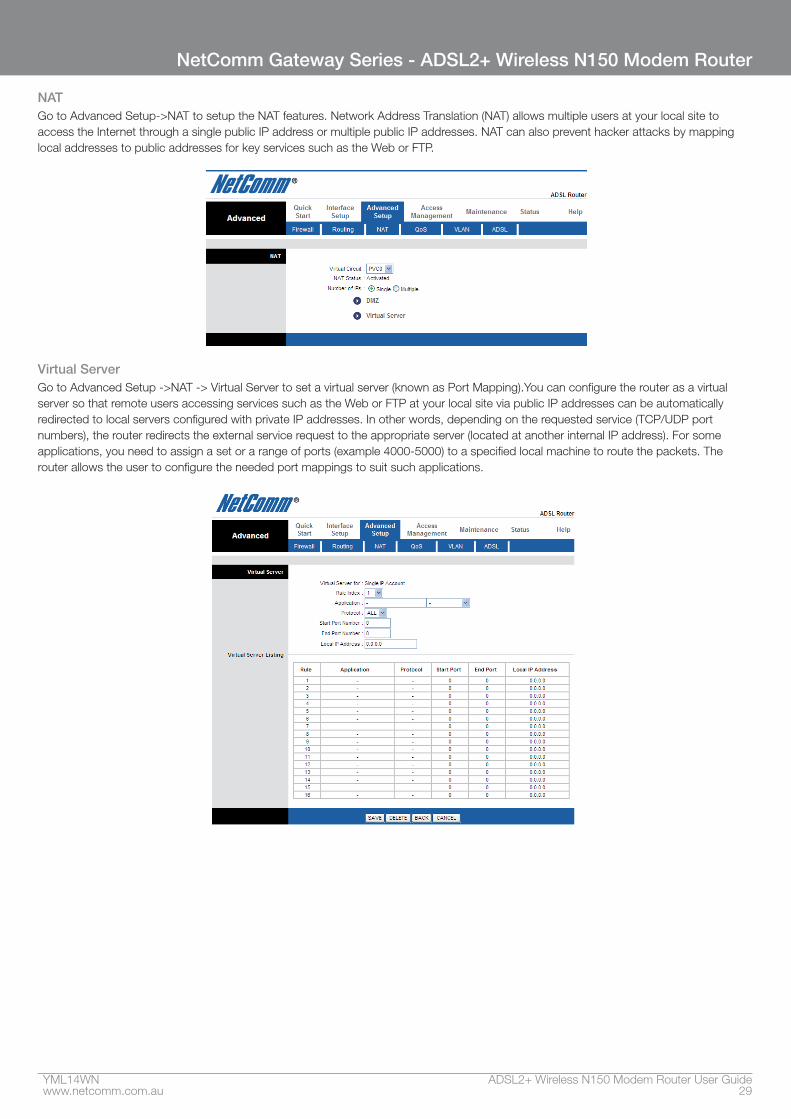
NATGo to Advanced Setup->NAT to setup the NAT features. Network Address Translation (NAT) allows multiple users at your local site to access the Internet through a single public IP address or multiple public IP addresses. NAT can also prevent hacker attacks by mapping local addresses to public addresses for key services such as the Web or FTP.
Virtual ServerGo to Advanced Setup ->NAT -> Virtual Server to set a virtual server (known as Port Mapping).You can configure the router as a virtual server so that remote users accessing services such as the Web or FTP at your local site via public IP addresses can be automatically redirected to local servers configured with private IP addresses. In other words, depending on the requested service (TCP/UDP port numbers), the router redirects the external service request to the appropriate server (located at another internal IP address). For some applications, you need to assign a set or a range of ports (example 4000-5000) to a specified local machine to route the packets. The router allows the user to configure the needed port mappings to suit such applications.
ADSL2+ Wireless N150 Modem Router User Guide YML14WN30 www.netcomm.com.au
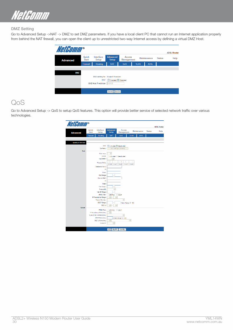
DMZ SettingGo to Advanced Setup ->NAT -> DMZ to set DMZ parameters. If you have a local client PC that cannot run an Internet application properly from behind the NAT firewall, you can open the client up to unrestricted two-way Internet access by defining a virtual DMZ Host.
QoSGo to Advanced Setup -> QoS to setup QoS features. This option will provide better service of selected network traffic over various technologies.
YML14WN ADSL2+ Wireless N150 Modem Router User Guidewww.netcomm.com.au 31
NetComm Gateway Series - ADSL2+ Wireless N150 Modem Router
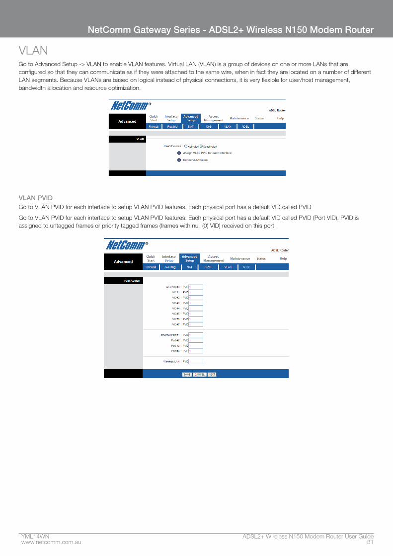
VLANGo to Advanced Setup -> VLAN to enable VLAN features. Virtual LAN (VLAN) is a group of devices on one or more LANs that are configured so that they can communicate as if they were attached to the same wire, when in fact they are located on a number of different LAN segments. Because VLANs are based on logical instead of physical connections, it is very flexible for user/host management, bandwidth allocation and resource optimization.
VLAN PVIDGo to VLAN PVID for each interface to setup VLAN PVID features. Each physical port has a default VID called PVID
Go to VLAN PVID for each interface to setup VLAN PVID features. Each physical port has a default VID called PVID (Port VID). PVID is assigned to untagged frames or priority tagged frames (frames with null (0) VID) received on this port.
ADSL2+ Wireless N150 Modem Router User Guide YML14WN32 www.netcomm.com.au
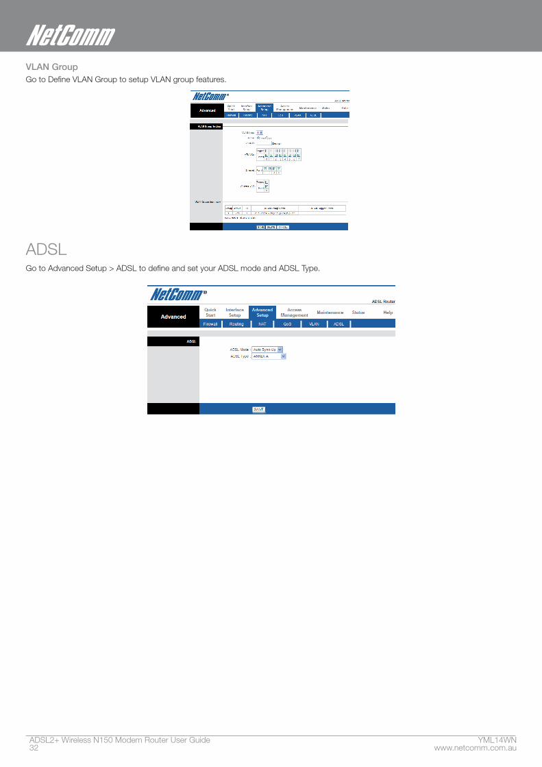
VLAN GroupGo to Define VLAN Group to setup VLAN group features.
ADSLGo to Advanced Setup > ADSL to define and set your ADSL mode and ADSL Type.

Access Management
ADSL2+ Wireless N150 Modem Router User Guide YML14WN34 www.netcomm.com.au
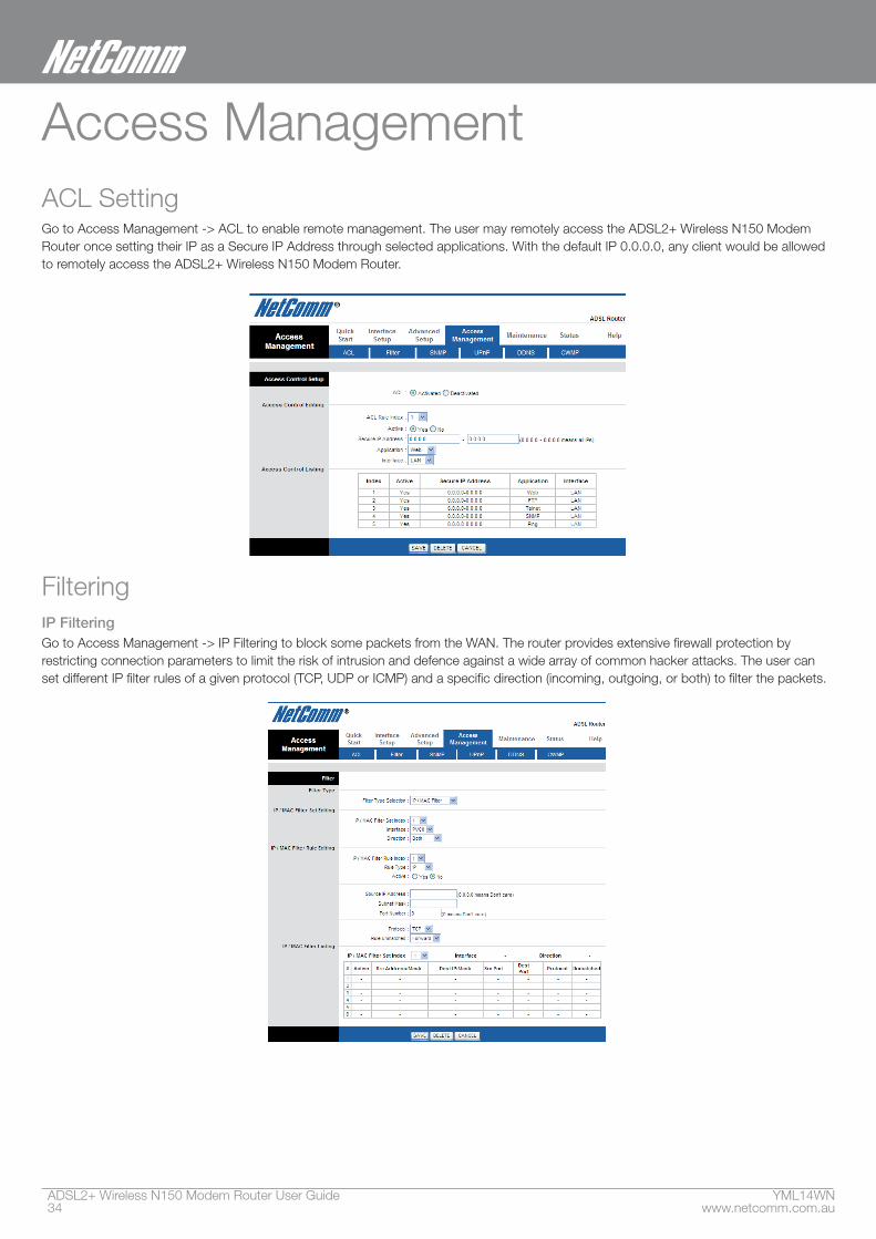
Access ManagementACL Setting Go to Access Management -> ACL to enable remote management. The user may remotely access the ADSL2+ Wireless N150 Modem Router once setting their IP as a Secure IP Address through selected applications. With the default IP 0.0.0.0, any client would be allowed to remotely access the ADSL2+ Wireless N150 Modem Router.
FilteringIP Filtering Go to Access Management -> IP Filtering to block some packets from the WAN. The router provides extensive firewall protection by restricting connection parameters to limit the risk of intrusion and defence against a wide array of common hacker attacks. The user can set different IP filter rules of a given protocol (TCP, UDP or ICMP) and a specific direction (incoming, outgoing, or both) to filter the packets.
YML14WN ADSL2+ Wireless N150 Modem Router User Guidewww.netcomm.com.au 35
NetComm Gateway Series - ADSL2+ Wireless N150 Modem Router
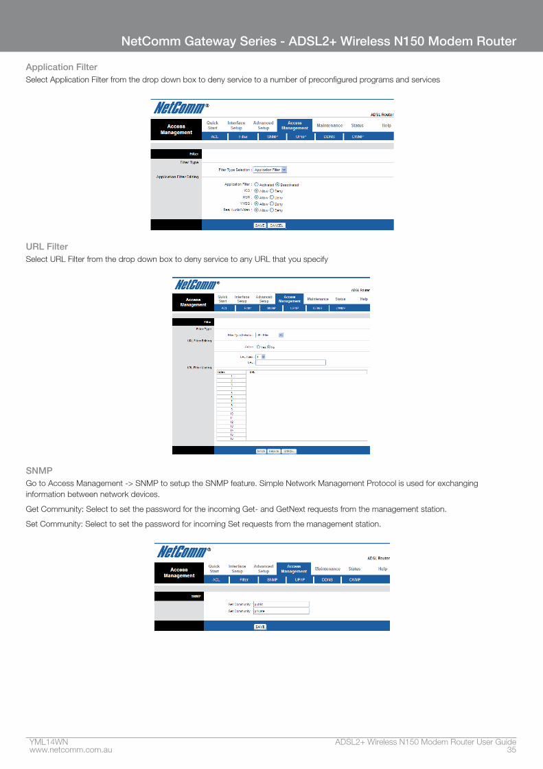
Application FilterSelect Application Filter from the drop down box to deny service to a number of preconfigured programs and services
URL FilterSelect URL Filter from the drop down box to deny service to any URL that you specify
SNMPGo to Access Management -> SNMP to setup the SNMP feature. Simple Network Management Protocol is used for exchanging information between network devices.
Get Community: Select to set the password for the incoming Get- and GetNext requests from the management station.
Set Community: Select to set the password for incoming Set requests from the management station.
ADSL2+ Wireless N150 Modem Router User Guide YML14WN36 www.netcomm.com.au
Universal Plug-and-Play (UPnP)Universal Plug and Play OverviewUniversal Plug and Play (UPnP) is a distributed, open networking standard that uses TCP/IP for simple peer-to-peer network connectivity between devices. An UPnP device can dynamically join a network, obtain an IP address, convey its capabilities and learn about other devices on the network. In turn, a device can leave a network smoothly and automatically when it is no longer in use.
How do I know if I’m using UPnP?UPnP hardware is identified as an icon in the Network Connections folder (Windows XP). Each UPnP compatible device installed on your network will appear as a separate icon. Selecting the icon of a UPnP device will allow you to access the information and properties of that device.
NAT TraversalUPnP NAT traversal automates the process of allowing an application to operate through NAT. UPnP network devices can automatically configure network addressing, announce their presence in the network to other UPnP devices and enable exchange of simple product and service descriptions. NAT traversal allows the following:
• Dynamic port mapping
• Learning public IP addresses
• Assigning lease times to mappings
Windows Messenger is an example of an application that supports NAT traversal and UPnP.
See the Network Address Translation (NAT) chapter for further information about NAT.
Cautions with UPnPThe automated nature of NAT traversal applications in establishing their own services may present network security issues. Network information and configuration may also be obtained and modified by users in some network environments.
All UPnP-enabled devices may communicate freely with each other without additional configuration. Disable UPnP if this is not your intention.
UPnP broadcasts are only allowed on the LAN.
See later sections for examples of installing UPnP in Windows XP and Windows Me as well as an example of using UPnP in Windows.
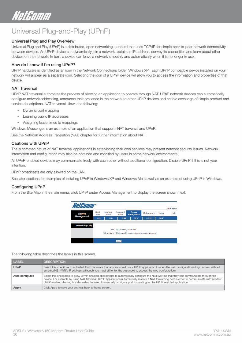
Configuring UPnPFrom the Site Map in the main menu, click UPnP under Access Management to display the screen shown next.
The following table describes the labels in this screen.
LABEL DESCRIPTION
UPnP Select this checkbox to activate UPnP. Be aware that anyone could use a UPnP application to open the web configuration’s login screen without entering NB14WN’s IP address (although you must still enter the password to access the web configuration).
Auto configured Select this check box to allow UPnP-enabled applications to automatically configure the NB14WN so that they can communicate through the device. For example by using NAT traversal, UPnP applications automatically reserve a NAT forwarding port in order to communicate with another UPnP enabled device; this eliminates the need to manually configure port forwarding for the UPnP enabled application.
Apply Click Apply to save your settings back to home screen.
YML14WN ADSL2+ Wireless N150 Modem Router User Guidewww.netcomm.com.au 37
NetComm Gateway Series - ADSL2+ Wireless N150 Modem Router
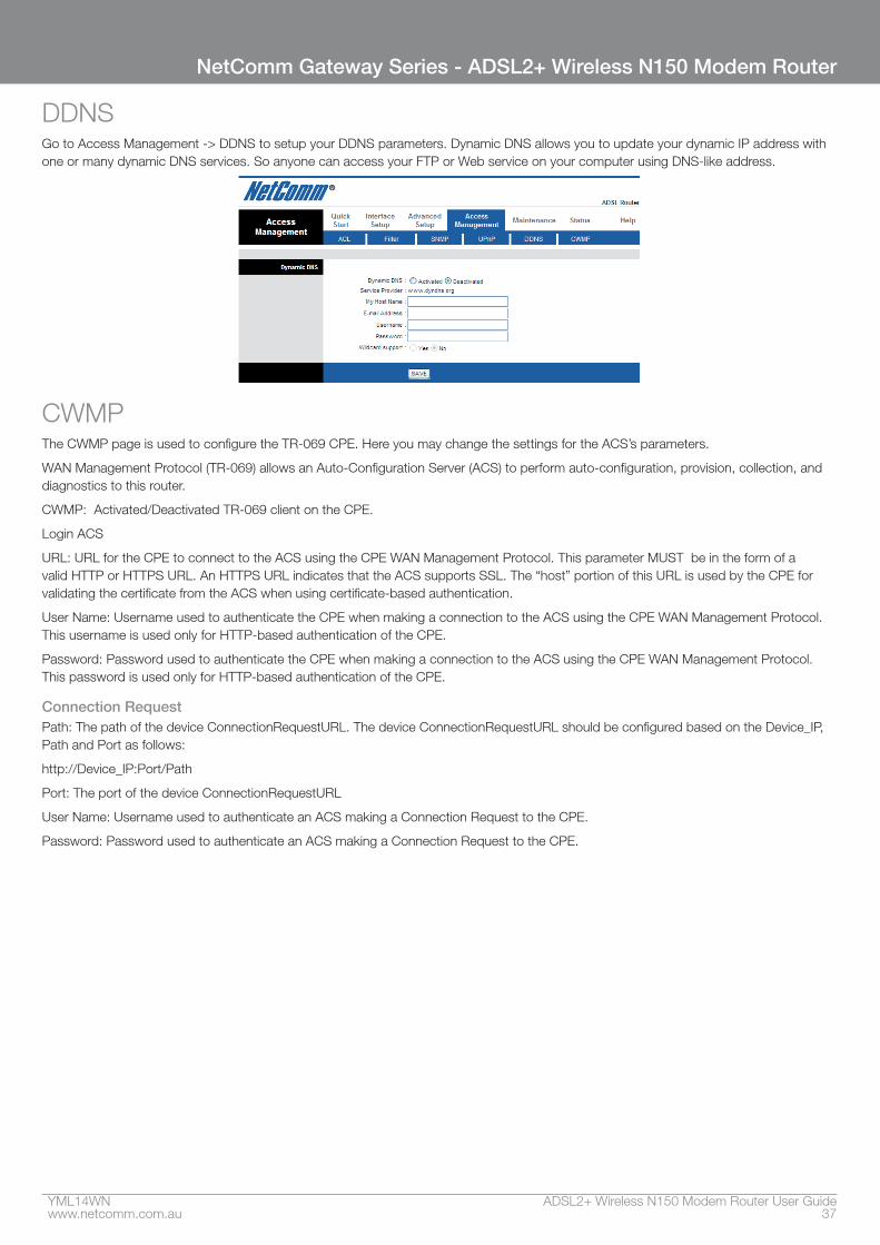
DDNSGo to Access Management -> DDNS to setup your DDNS parameters. Dynamic DNS allows you to update your dynamic IP address with one or many dynamic DNS services. So anyone can access your FTP or Web service on your computer using DNS-like address.
CWMPThe CWMP page is used to configure the TR-069 CPE. Here you may change the settings for the ACS’s parameters.
WAN Management Protocol (TR-069) allows an Auto-Configuration Server (ACS) to perform auto-configuration, provision, collection, and diagnostics to this router.
CWMP: Activated/Deactivated TR-069 client on the CPE.
Login ACS
URL: URL for the CPE to connect to the ACS using the CPE WAN Management Protocol. This parameter MUST be in the form of a valid HTTP or HTTPS URL. An HTTPS URL indicates that the ACS supports SSL. The “host” portion of this URL is used by the CPE for validating the certificate from the ACS when using certificate-based authentication.
User Name: Username used to authenticate the CPE when making a connection to the ACS using the CPE WAN Management Protocol. This username is used only for HTTP-based authentication of the CPE.
Password: Password used to authenticate the CPE when making a connection to the ACS using the CPE WAN Management Protocol. This password is used only for HTTP-based authentication of the CPE.
Connection RequestPath: The path of the device ConnectionRequestURL. The device ConnectionRequestURL should be configured based on the Device_IP, Path and Port as follows:
http://Device_IP:Port/Path
Port: The port of the device ConnectionRequestURL
User Name: Username used to authenticate an ACS making a Connection Request to the CPE.
Password: Password used to authenticate an ACS making a Connection Request to the CPE.
ADSL2+ Wireless N150 Modem Router User Guide YML14WN38 www.netcomm.com.au
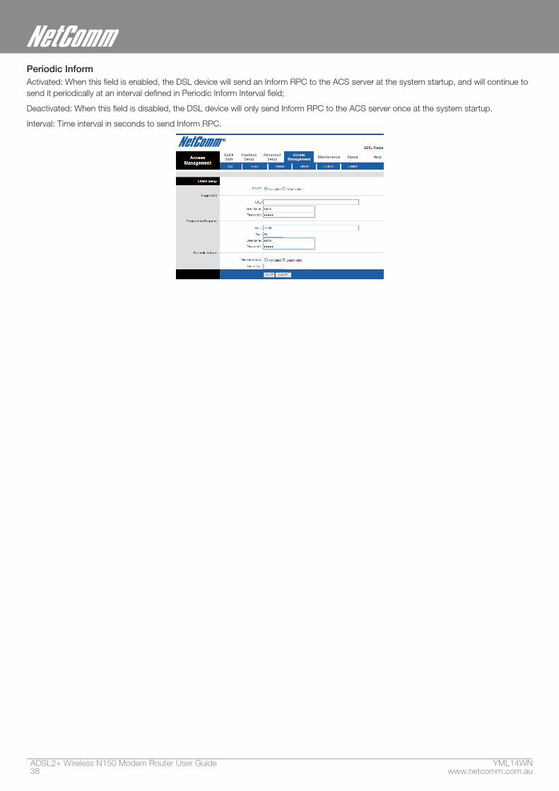
Periodic InformActivated: When this field is enabled, the DSL device will send an Inform RPC to the ACS server at the system startup, and will continue to send it periodically at an interval defined in Periodic Inform Interval field;
Deactivated: When this field is disabled, the DSL device will only send Inform RPC to the ACS server once at the system startup.
Interval: Time interval in seconds to send Inform RPC.

Maintenance
ADSL2+ Wireless N150 Modem Router User Guide YML14WN40 www.netcomm.com.au
Maintenance
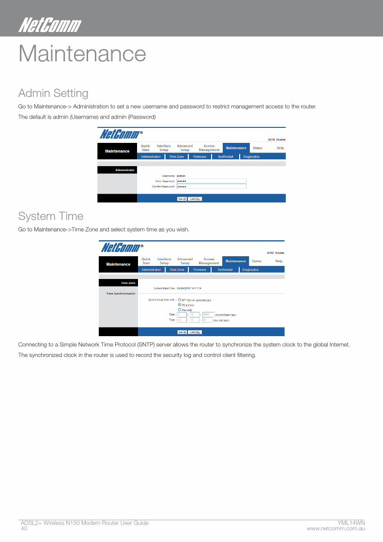
Admin SettingGo to Maintenance-> Administration to set a new username and password to restrict management access to the router.
The default is admin (Username) and admin (Password)
System TimeGo to Maintenance->Time Zone and select system time as you wish.
Connecting to a Simple Network Time Protocol (SNTP) server allows the router to synchronize the system clock to the global Internet.
The synchronized clock in the router is used to record the security log and control client filtering.
YML14WN ADSL2+ Wireless N150 Modem Router User Guidewww.netcomm.com.au 41
NetComm Gateway Series - ADSL2+ Wireless N150 Modem Router
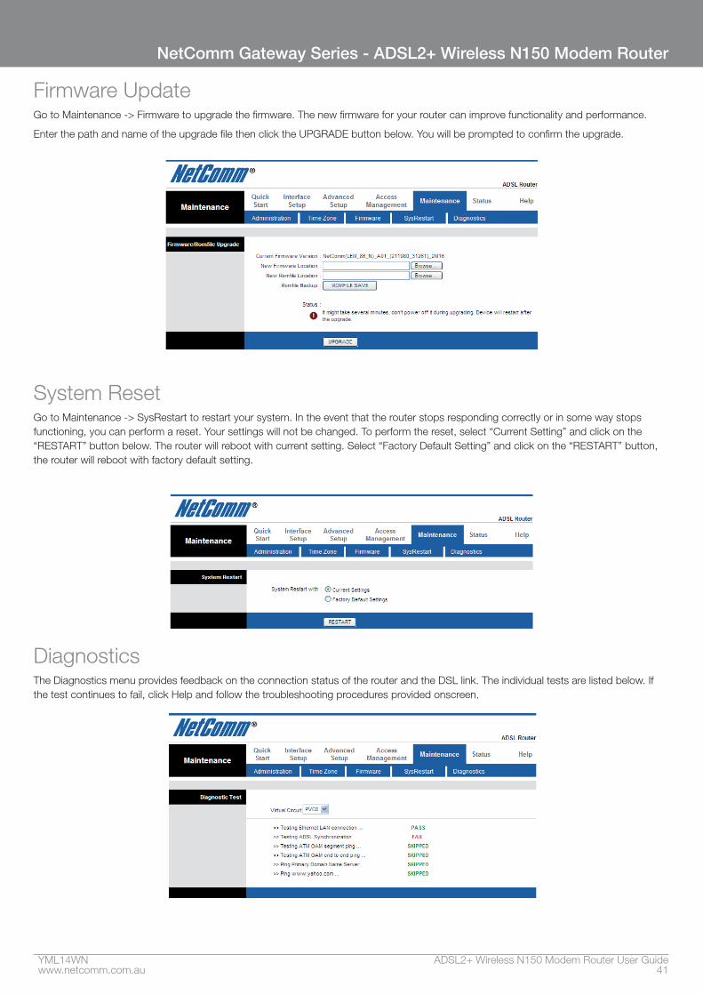
Firmware UpdateGo to Maintenance -> Firmware to upgrade the firmware. The new firmware for your router can improve functionality and performance.
Enter the path and name of the upgrade file then click the UPGRADE button below. You will be prompted to confirm the upgrade.
System ResetGo to Maintenance -> SysRestart to restart your system. In the event that the router stops responding correctly or in some way stops functioning, you can perform a reset. Your settings will not be changed. To perform the reset, select “Current Setting” and click on the “RESTART” button below. The router will reboot with current setting. Select “Factory Default Setting” and click on the “RESTART” button, the router will reboot with factory default setting.
DiagnosticsThe Diagnostics menu provides feedback on the connection status of the router and the DSL link. The individual tests are listed below. If the test continues to fail, click Help and follow the troubleshooting procedures provided onscreen.

Status
YML14WN ADSL2+ Wireless N150 Modem Router User Guidewww.netcomm.com.au 43
NetComm Gateway Series - ADSL2+ Wireless N150 Modem Router
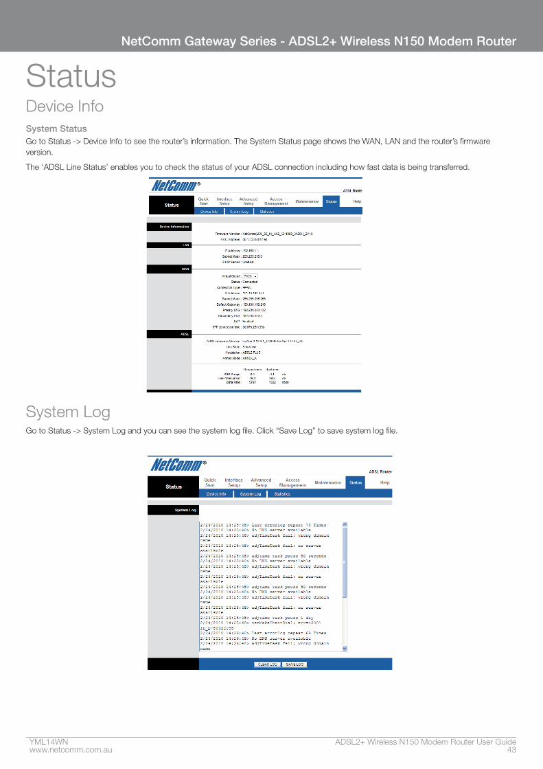
StatusDevice InfoSystem StatusGo to Status -> Device Info to see the router’s information. The System Status page shows the WAN, LAN and the router’s firmware version.
The ‘ADSL Line Status’ enables you to check the status of your ADSL connection including how fast data is being transferred.
System LogGo to Status -> System Log and you can see the system log file. Click “Save Log” to save system log file.
ADSL2+ Wireless N150 Modem Router User Guide YML14WN44 www.netcomm.com.au
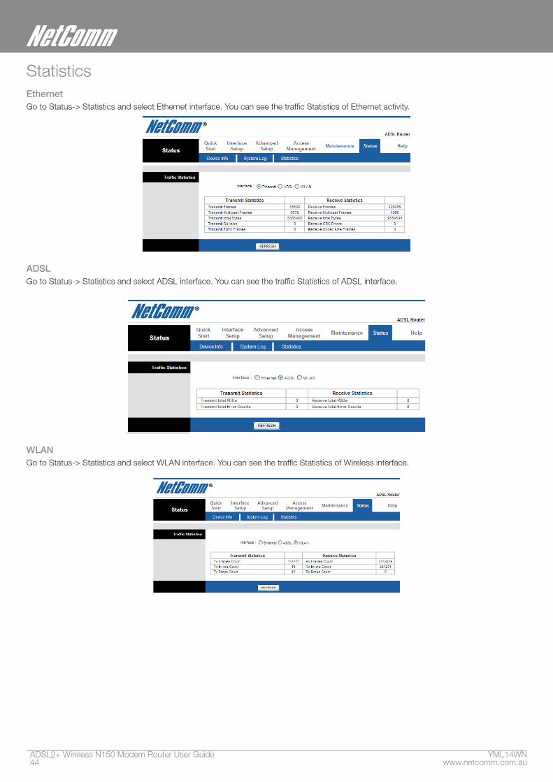
StatisticsEthernetGo to Status-> Statistics and select Ethernet interface. You can see the traffic Statistics of Ethernet activity.
ADSLGo to Status-> Statistics and select ADSL interface. You can see the traffic Statistics of ADSL interface.
WLANGo to Status-> Statistics and select WLAN interface. You can see the traffic Statistics of Wireless interface.

Appendix
ADSL2+ Wireless N150 Modem Router User Guide YML14WN46 www.netcomm.com.au
Appendix A: Installing UPnP in Windows Example
This section shows how to install UPnP in Windows Me and Windows XP.
Installing UPnP in Windows MeFollow the steps below to install the UPnP in Windows Me.
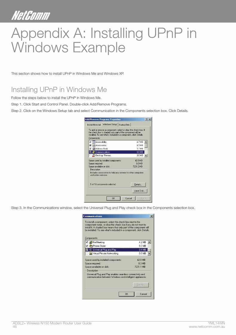
Step 1. Click Start and Control Panel. Double-click Add/Remove Programs.
Step 2. Click on the Windows Setup tab and select Communication in the Components selection box. Click Details.
Step 3. In the Communications window, select the Universal Plug and Play check box in the Components selection box.
YML14WN ADSL2+ Wireless N150 Modem Router User Guidewww.netcomm.com.au 47
NetComm Gateway Series - ADSL2+ Wireless N150 Modem Router
Step 4. Click OK to go back to the Add/Remove Programs Properties window and click Next.
Step 5. Restart the computer when prompted.
Installing UPnP in Windows XPFollow the steps below to install the UPnP in Windows XP.
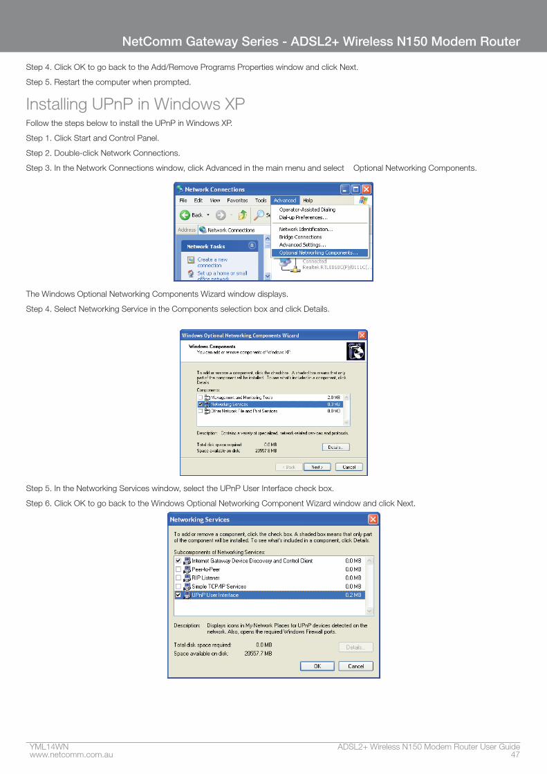
Step 1. Click Start and Control Panel.
Step 2. Double-click Network Connections.
Step 3. In the Network Connections window, click Advanced in the main menu and select Optional Networking Components.
The Windows Optional Networking Components Wizard window displays.
Step 4. Select Networking Service in the Components selection box and click Details.
Step 5. In the Networking Services window, select the UPnP User Interface check box.
Step 6. Click OK to go back to the Windows Optional Networking Component Wizard window and click Next.
ADSL2+ Wireless N150 Modem Router User Guide YML14WN48 www.netcomm.com.au
Using UPnP in Windows XP ExampleThis section shows you how to use the UPnP feature in Windows XP. You must already have UPnP installed in Windows XP and UPnP activated on the NB14WN.
Make sure the computer is connected to a LAN port of the NB14WN. Turn on your computer and the NB14WN.
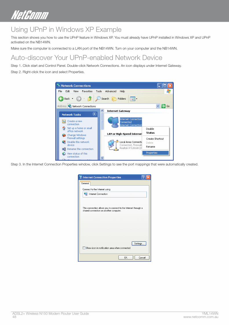
Auto-discover Your UPnP-enabled Network DeviceStep 1. Click start and Control Panel. Double-click Network Connections. An icon displays under Internet Gateway.
Step 2. Right-click the icon and select Properties.
Step 3. In the Internet Connection Properties window, click Settings to see the port mappings that were automatically created.
YML14WN ADSL2+ Wireless N150 Modem Router User Guidewww.netcomm.com.au 49
NetComm Gateway Series - ADSL2+ Wireless N150 Modem Router
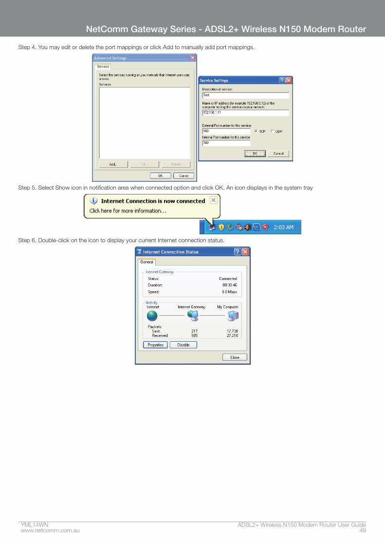
Step 4. You may edit or delete the port mappings or click Add to manually add port mappings.
Step 5. Select Show icon in notification area when connected option and click OK. An icon displays in the system tray
Step 6. Double-click on the icon to display your current Internet connection status.
ADSL2+ Wireless N150 Modem Router User Guide YML14WN50 www.netcomm.com.au
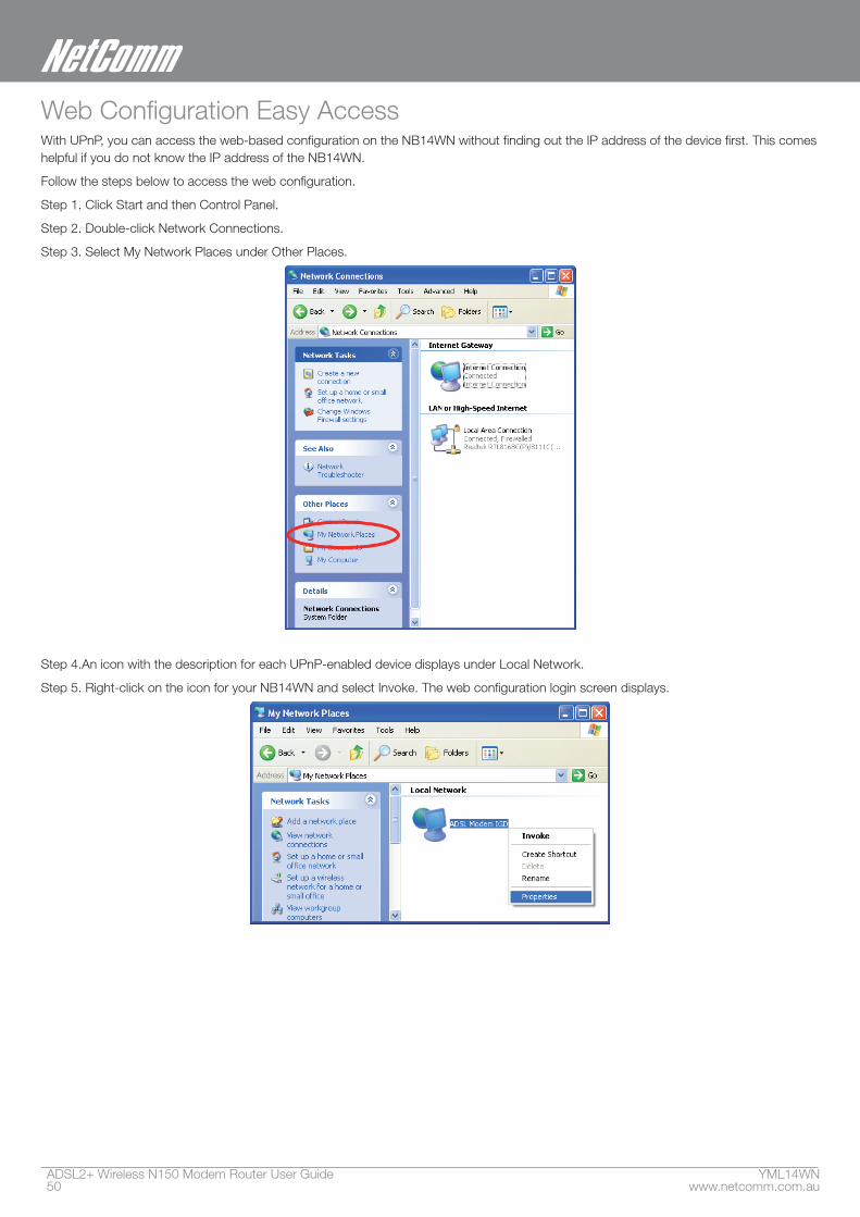
Web Configuration Easy AccessWith UPnP, you can access the web-based configuration on the NB14WN without finding out the IP address of the device first. This comes helpful if you do not know the IP address of the NB14WN.
Follow the steps below to access the web configuration.
Step 1. Click Start and then Control Panel.
Step 2. Double-click Network Connections.
Step 3. Select My Network Places under Other Places.
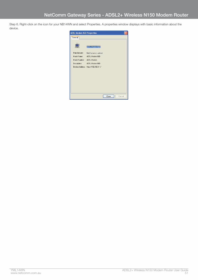
Step 4.An icon with the description for each UPnP-enabled device displays under Local Network.
Step 5. Right-click on the icon for your NB14WN and select Invoke. The web configuration login screen displays.
YML14WN ADSL2+ Wireless N150 Modem Router User Guidewww.netcomm.com.au 51
NetComm Gateway Series - ADSL2+ Wireless N150 Modem Router
Step 6. Right-click on the icon for your NB14WN and select Properties. A properties window displays with basic information about the device.
ADSL2+ Wireless N150 Modem Router User Guide YML14WN52 www.netcomm.com.au
Appendix B: Troubleshooting
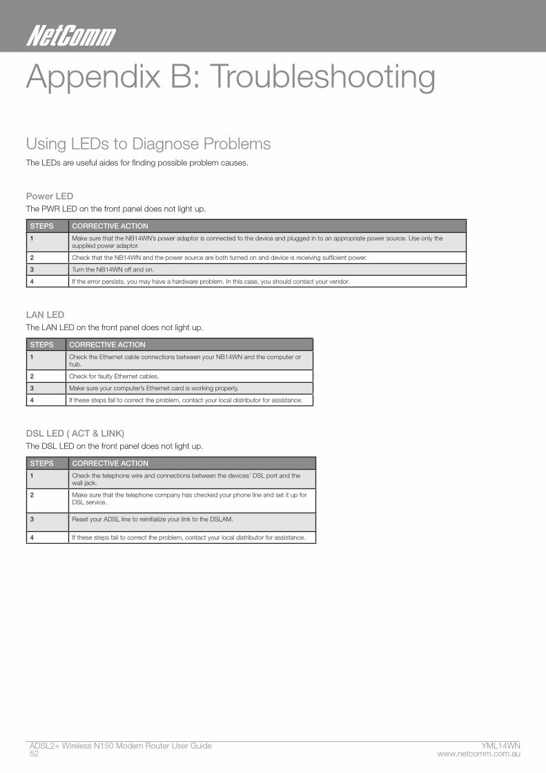
Using LEDs to Diagnose ProblemsThe LEDs are useful aides for finding possible problem causes.
Power LEDThe PWR LED on the front panel does not light up.
STEPS CORRECTIVE ACTION
1 Make sure that the NB14WN’s power adaptor is connected to the device and plugged in to an appropriate power source. Use only the supplied power adaptor.
2 Check that the NB14WN and the power source are both turned on and device is receiving sufficient power.
3 Turn the NB14WN off and on.
4 If the error persists, you may have a hardware problem. In this case, you should contact your vendor.
LAN LEDThe LAN LED on the front panel does not light up.
STEPS CORRECTIVE ACTION
1 Check the Ethernet cable connections between your NB14WN and the computer or hub.
2 Check for faulty Ethernet cables.
3 Make sure your computer’s Ethernet card is working properly.
4 If these steps fail to correct the problem, contact your local distributor for assistance.
DSL LED ( ACT & LINK)The DSL LED on the front panel does not light up.
STEPS CORRECTIVE ACTION
1 Check the telephone wire and connections between the devices’ DSL port and the wall jack.
2 Make sure that the telephone company has checked your phone line and set it up for DSL service.
3 Reset your ADSL line to reinitialize your link to the DSLAM.
4 If these steps fail to correct the problem, contact your local distributor for assistance.
YML14WN ADSL2+ Wireless N150 Modem Router User Guidewww.netcomm.com.au 53
NetComm Gateway Series - ADSL2+ Wireless N150 Modem Router
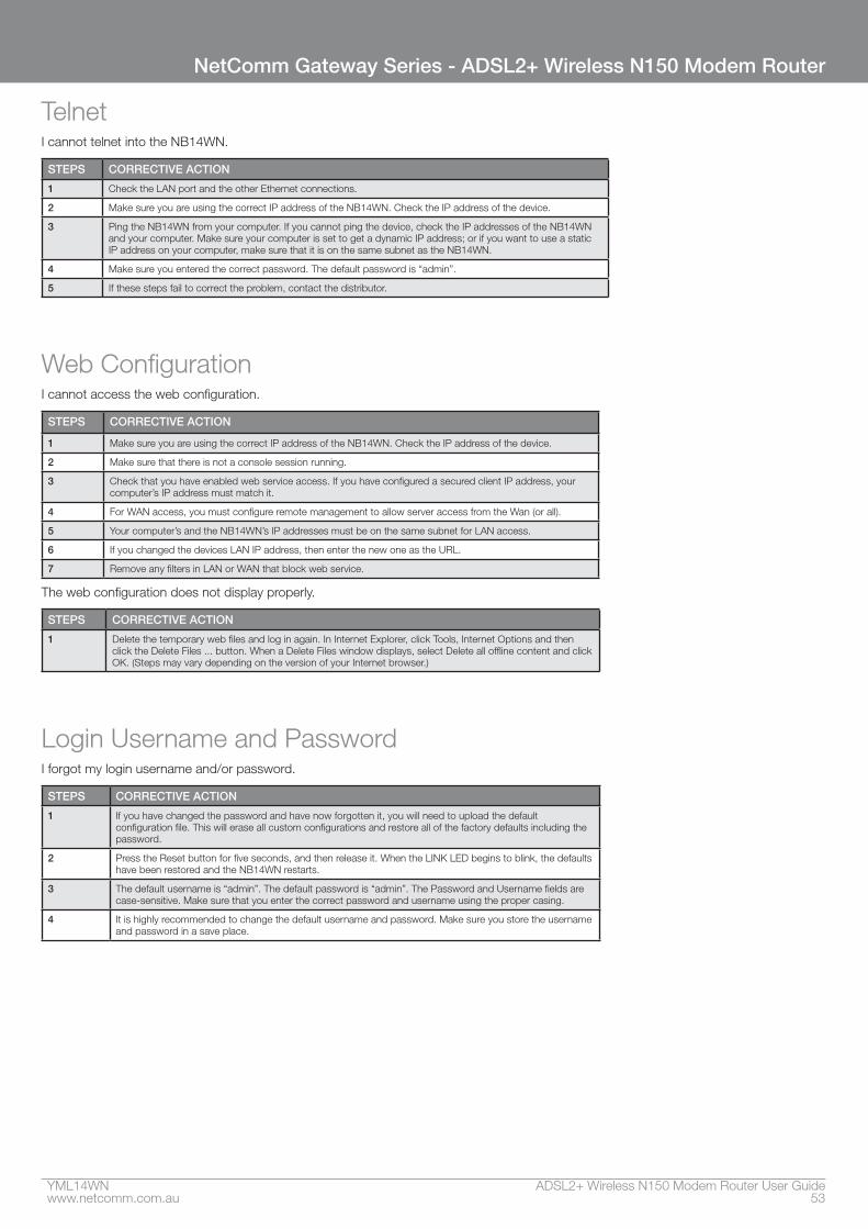
TelnetI cannot telnet into the NB14WN.
STEPS CORRECTIVE ACTION
1 Check the LAN port and the other Ethernet connections.
2 Make sure you are using the correct IP address of the NB14WN. Check the IP address of the device.
3 Ping the NB14WN from your computer. If you cannot ping the device, check the IP addresses of the NB14WN and your computer. Make sure your computer is set to get a dynamic IP address; or if you want to use a static IP address on your computer, make sure that it is on the same subnet as the NB14WN.
4 Make sure you entered the correct password. The default password is “admin”.
5 If these steps fail to correct the problem, contact the distributor.
Web ConfigurationI cannot access the web configuration.
STEPS CORRECTIVE ACTION
1 Make sure you are using the correct IP address of the NB14WN. Check the IP address of the device.
2 Make sure that there is not a console session running.
3 Check that you have enabled web service access. If you have configured a secured client IP address, your computer’s IP address must match it.
4 For WAN access, you must configure remote management to allow server access from the Wan (or all).
5 Your computer’s and the NB14WN’s IP addresses must be on the same subnet for LAN access.
6 If you changed the devices LAN IP address, then enter the new one as the URL.
7 Remove any filters in LAN or WAN that block web service.
The web configuration does not display properly.
STEPS CORRECTIVE ACTION
1 Delete the temporary web files and log in again. In Internet Explorer, click Tools, Internet Options and then click the Delete Files ... button. When a Delete Files window displays, select Delete all offline content and click OK. (Steps may vary depending on the version of your Internet browser.)
Login Username and PasswordI forgot my login username and/or password.
STEPS CORRECTIVE ACTION
1 If you have changed the password and have now forgotten it, you will need to upload the default configuration file. This will erase all custom configurations and restore all of the factory defaults including the password.
2 Press the Reset button for five seconds, and then release it. When the LINK LED begins to blink, the defaults have been restored and the NB14WN restarts.
3 The default username is “admin”. The default password is “admin”. The Password and Username fields are case-sensitive. Make sure that you enter the correct password and username using the proper casing.
4 It is highly recommended to change the default username and password. Make sure you store the username and password in a save place.
ADSL2+ Wireless N150 Modem Router User Guide YML14WN54 www.netcomm.com.au
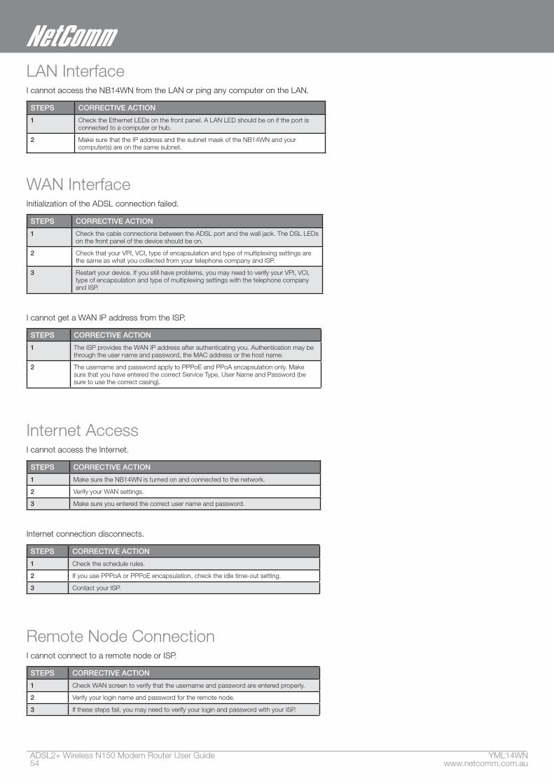
LAN InterfaceI cannot access the NB14WN from the LAN or ping any computer on the LAN.
STEPS CORRECTIVE ACTION
1 Check the Ethernet LEDs on the front panel. A LAN LED should be on if the port is connected to a computer or hub.
2 Make sure that the IP address and the subnet mask of the NB14WN and your computer(s) are on the same subnet.
WAN InterfaceInitialization of the ADSL connection failed.
STEPS CORRECTIVE ACTION
1 Check the cable connections between the ADSL port and the wall jack. The DSL LEDs on the front panel of the device should be on.
2 Check that your VPI, VCI, type of encapsulation and type of multiplexing settings are the same as what you collected from your telephone company and ISP.
3 Restart your device. If you still have problems, you may need to verify your VPI, VCI, type of encapsulation and type of multiplexing settings with the telephone company and ISP.
I cannot get a WAN IP address from the ISP.
STEPS CORRECTIVE ACTION
1 The ISP provides the WAN IP address after authenticating you. Authentication may be through the user name and password, the MAC address or the host name.
2 The username and password apply to PPPoE and PPoA encapsulation only. Make sure that you have entered the correct Service Type, User Name and Password (be sure to use the correct casing).
Internet AccessI cannot access the Internet.
STEPS CORRECTIVE ACTION
1 Make sure the NB14WN is turned on and connected to the network.
2 Verify your WAN settings.
3 Make sure you entered the correct user name and password.
Internet connection disconnects.
STEPS CORRECTIVE ACTION
1 Check the schedule rules.
2 If you use PPPoA or PPPoE encapsulation, check the idle time-out setting.
3 Contact your ISP.
Remote Node ConnectionI cannot connect to a remote node or ISP.
STEPS CORRECTIVE ACTION
1 Check WAN screen to verify that the username and password are entered properly.
2 Verify your login name and password for the remote node.
3 If these steps fail, you may need to verify your login and password with your ISP.

YML14WN ADSL2+ Wireless N150 Modem Router User Guidewww.netcomm.com.au 55
NetComm Gateway Series - ADSL2+ Wireless N150 Modem Router
Appendix C: Technology Glossary
10Base-TAn adaptation of the Ethernet standard for Local Area Network (LAN). 10Base-T uses a twisted pair cable with maximum length of 100 meters.
AALATM Adaptation Layer that defines the rules governing segmentation and reassembly of data into cells. Different AAL types are suited to different traffic classes.
Address mask A bit mask used to select bits from an Internet address for subnet addressing. The mask is 32 bits long and selects the network portion of the Internet address and one or more bits of the local portion. Sometimes called subnet mask.
ADSLAsymmetric Digital Subscriber Line, as it’s name showing, is an asymmetrical data transmission technology with high traffic rate downstream and low traffic rate upstream. ADSL technology satisfies the bandwidth requirement of applications, which demand “asymmetric” traffic, such as web surfing, file download and Video-on-demand (VOD).
ATM Asynchronous Transfer Mode is a layer 2 protocol supporting high-speed asynchronous data with advanced traffic management and quality of service features.
bpsBits per second. A standard measurement of digital transmission speeds.
BridgeA device that connects two or more physical networks and forwards packets between them. Bridges can usually be made to filter packets, that is, to forward only certain traffic. Related devices are: repeaters which simply forward electrical signals from one cable to the other, and full-fledged routers which make routing decisions based on several criteria.
CPECustomer Premises Equipment, such as ADSL router, USB modem.
DHCPDynamic Host Configuration Protocol. Used for assigning dynamic IP address to devices on a network. Used by ISPs for dialup users.
DNSDomain Name Server, translates domain names into IP
addresses to help user recognize and remember. However, the Internet actually runs on numbered IP addresses, DNS servers needs to translate domain names back to their respective IP addresses.
ADSL2+ Wireless N150 Modem Router User Guide YML14WN56 www.netcomm.com.au
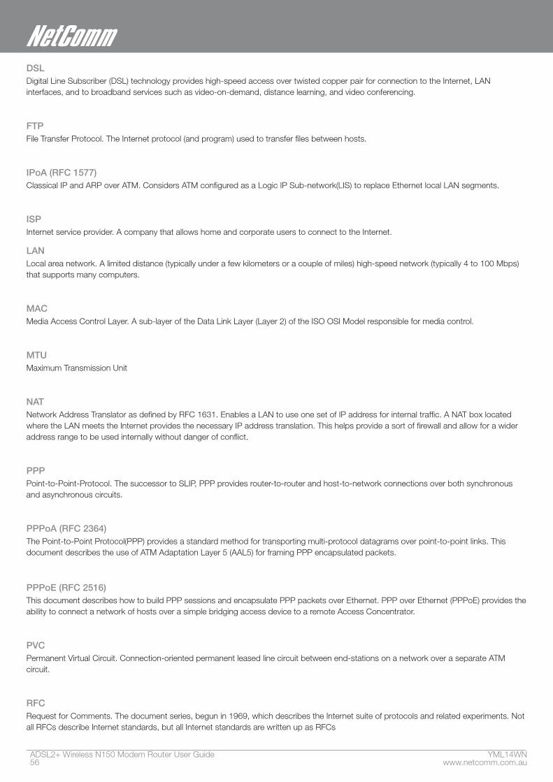
DSLDigital Line Subscriber (DSL) technology provides high-speed access over twisted copper pair for connection to the Internet, LAN interfaces, and to broadband services such as video-on-demand, distance learning, and video conferencing.
FTPFile Transfer Protocol. The Internet protocol (and program) used to transfer files between hosts.
IPoA (RFC 1577)Classical IP and ARP over ATM. Considers ATM configured as a Logic IP Sub-network(LIS) to replace Ethernet local LAN segments.
ISPInternet service provider. A company that allows home and corporate users to connect to the Internet.
LANLocal area network. A limited distance (typically under a few kilometers or a couple of miles) high-speed network (typically 4 to 100 Mbps) that supports many computers.
MACMedia Access Control Layer. A sub-layer of the Data Link Layer (Layer 2) of the ISO OSI Model responsible for media control.
MTUMaximum Transmission Unit
NATNetwork Address Translator as defined by RFC 1631. Enables a LAN to use one set of IP address for internal traffic. A NAT box located where the LAN meets the Internet provides the necessary IP address translation. This helps provide a sort of firewall and allow for a wider address range to be used internally without danger of conflict.
PPPPoint-to-Point-Protocol. The successor to SLIP, PPP provides router-to-router and host-to-network connections over both synchronous and asynchronous circuits.
PPPoA (RFC 2364)The Point-to-Point Protocol(PPP) provides a standard method for transporting multi-protocol datagrams over point-to-point links. This document describes the use of ATM Adaptation Layer 5 (AAL5) for framing PPP encapsulated packets.
PPPoE (RFC 2516)This document describes how to build PPP sessions and encapsulate PPP packets over Ethernet. PPP over Ethernet (PPPoE) provides the ability to connect a network of hosts over a simple bridging access device to a remote Access Concentrator.
PVCPermanent Virtual Circuit. Connection-oriented permanent leased line circuit between end-stations on a network over a separate ATM circuit.
RFCRequest for Comments. The document series, begun in 1969, which describes the Internet suite of protocols and related experiments. Not all RFCs describe Internet standards, but all Internet standards are written up as RFCs
YML14WN ADSL2+ Wireless N150 Modem Router User Guidewww.netcomm.com.au 57
NetComm Gateway Series - ADSL2+ Wireless N150 Modem Router
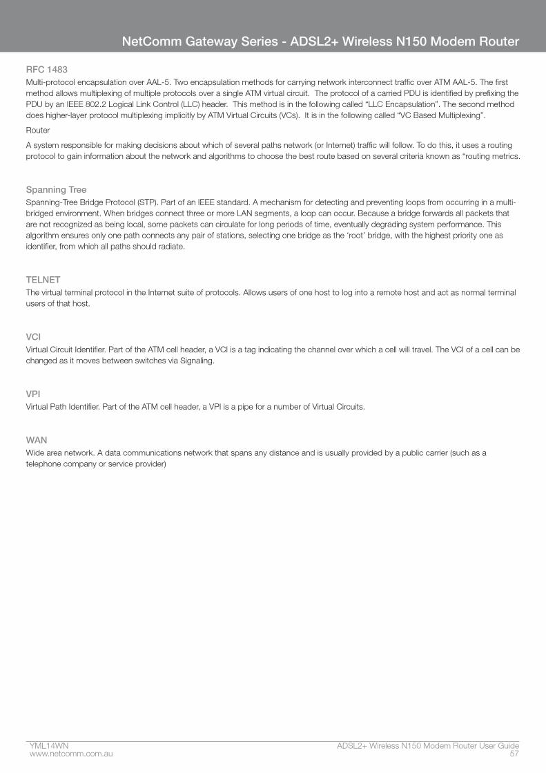
RFC 1483Multi-protocol encapsulation over AAL-5. Two encapsulation methods for carrying network interconnect traffic over ATM AAL-5. The first method allows multiplexing of multiple protocols over a single ATM virtual circuit. The protocol of a carried PDU is identified by prefixing the PDU by an IEEE 802.2 Logical Link Control (LLC) header. This method is in the following called “LLC Encapsulation”. The second method does higher-layer protocol multiplexing implicitly by ATM Virtual Circuits (VCs). It is in the following called “VC Based Multiplexing”.
Router
A system responsible for making decisions about which of several paths network (or Internet) traffic will follow. To do this, it uses a routing protocol to gain information about the network and algorithms to choose the best route based on several criteria known as “routing metrics.
Spanning TreeSpanning-Tree Bridge Protocol (STP). Part of an IEEE standard. A mechanism for detecting and preventing loops from occurring in a multi-bridged environment. When bridges connect three or more LAN segments, a loop can occur. Because a bridge forwards all packets that are not recognized as being local, some packets can circulate for long periods of time, eventually degrading system performance. This algorithm ensures only one path connects any pair of stations, selecting one bridge as the ‘root’ bridge, with the highest priority one as identifier, from which all paths should radiate.
TELNETThe virtual terminal protocol in the Internet suite of protocols. Allows users of one host to log into a remote host and act as normal terminal users of that host.
VCIVirtual Circuit Identifier. Part of the ATM cell header, a VCI is a tag indicating the channel over which a cell will travel. The VCI of a cell can be changed as it moves between switches via Signaling.
VPIVirtual Path Identifier. Part of the ATM cell header, a VPI is a pipe for a number of Virtual Circuits.
WANWide area network. A data communications network that spans any distance and is usually provided by a public carrier (such as a telephone company or service provider)
ADSL2+ Wireless N150 Modem Router User Guide YML14WN58 www.netcomm.com.au
Appendix D: Legal & Regulatory InformationThis manual is copyright. Apart from any fair dealing for the purposes of private study, research, criticism or review, as permitted under the Copyright Act, no part may be reproduced, stored in a retrieval system or transmitted in any form, by any means, be it electronic, mechanical, recording or otherwise, without the prior written permission of NetComm Limited. NetComm Limited accepts no liability or responsibility, for consequences arising from the use of this product.
NetComm Limited reserves the right to change the specifications and operating details of this product without notice.
NetComm is a registered trademark of NetComm Limited.
All other trademarks are acknowledged the property of their respective owners.
Customer InformationACA (Australian Communications Authority) requires you to be aware of the following information and warnings:
(1) This unit shall be connected to the Telecommunication Network through a line cord which meets the requirements of the ACA TS008 Standard.
(2) This equipment has been tested and found to comply with the Standards for C-Tick and or A-Tick as set by the ACA . These standards are designed to provide reasonable protection against harmful interference in a residential installation. This equipment generates, uses, and can radiate radio noise and, if not installed and used in accordance with the instructions detailed within this manual, may cause interference to radio communications. However, there is no guarantee that interference will not occur with the installation of this product in your home or office. If this equipment does cause some degree of interference to radio or television reception, which can be determined by turning the equipment off and on, we encourage the user to try to correct the interference by one or more of the following measures:
• Change the direction or relocate the receiving antenna.
• Increase the separation between this equipment and the receiver.
• Connect the equipment to an alternate power outlet on a different power circuit from that to which the receiver/TV is connected.
• Consult an experienced radio/TV technician for help.
(3) The power supply that is provided with this unit is only intended for use with this product. Do not use this power supply with any other product or do not use any other power supply that is not approved for use with this product by NetComm. Failure to do so may cause damage to this product, fire or result in personal injury.
YML14WN ADSL2+ Wireless N150 Modem Router User Guidewww.netcomm.com.au 59
NetComm Gateway Series - ADSL2+ Wireless N150 Modem Router
Product WarrantyThe warranty is granted on the following conditions:
1. This warranty extends to the original purchaser (you) and is not transferable;
2. This warranty shall not apply to software programs, batteries, power supplies, cables or other accessories supplied in or with the product;
3. The customer complies with all of the terms of any relevant agreement with NetComm and any other reasonable requirements of NetComm including producing such evidence of purchase as NetComm may require;
4. The cost of transporting product to and from NetComm’s nominated premises is your responsibility; and,
5. NetComm does not have any liability or responsibility under this warranty where any cost, loss, injury or damage of any kind, whether direct, indirect, consequential, incidental or otherwise arises out of events beyond NetComm’s reasonable control. This includes but is not limited to: acts of God, war, riot, embargoes, acts of civil or military authorities, fire, floods, electricity outages, lightning, power surges, or shortages of materials or labour.
6. The customer is responsible for the security of their computer and network at all times. Security features may be disabled within the factory default settings. NetComm recommends that you enable these features to enhance your security.
ADSL2+ Wireless N150 Modem Router User Guide YML14WN60 www.netcomm.com.au
GNU General Public LicenseThis product includes software code that is subject to the GNU General Public License (“GPL”) or GNU Lesser General Public License (“LGPL”). This code is subject to the copyrights of one or more authors and is distributed without any warranty. A copy of this software can be obtained by contacting NetComm Limited on +61 2 9424 2059.
The warranty is automatically voided if:
1. You, or someone else, use the product, or attempts to use it, other than as specified by NetComm;
2. The fault or defect in your product is the result of a voltage surge subjected to the product either by the way of power supply or communication line, whether caused by thunderstorm activity or any other cause(s);
3. The fault is the result of accidental damage or damage in transit, including but not limited to liquid spillage;
4. Your product has been used for any purposes other than that for which it is sold, or in any way other than in strict accordance with the user manual supplied;
5. Your product has been repaired or modified or attempted to be repaired or modified, other than by a qualified person at a service centre authorised by NetComm; and,
6. The serial number has been defaced or altered in any way or if the serial number plate has been removed.
Limitations of WarrantyThe Trade Practices Act 1974 and corresponding State and Territory Fair Trading Acts or legalisation of another Government (“the relevant acts”) in certain circumstances imply mandatory conditions and warranties which cannot be excluded. This warranty is in addition to and not in replacement for such conditions and warranties.
To the extent permitted by the Relevant Acts, in relation to your product and any other materials provided with the product (“the Goods”) the liability of NetComm under the Relevant Acts is limited at the option of NetComm to:
• Replacement of the Goods; or
• Repair of the Goods; or
• Payment of the cost of replacing the Goods; or
• Payment of the cost of having the Goods repaired.
All NetComm ACN 002 490 486 products have a standard 12 months warranty from date of purchase. However some products have an extended warranty option (refer to packaging). To be eligible for the extended warranty you must supply the requested warranty information to NetComm within 30 days of the original purchase by registering on-line via the NetComm web site at www.netcomm.com.au
How to configure WEP/WPA-PSK/WPA2-PSK Wireless Security
Product WarrantyNetComm products have a standard 12 months warranty from date of purchase. However some products have an extended warranty option, via registering your product online at the NetComm website www.netcommlimited.com.
Technical SupportIf you have any technical difficulties with your product, please refer to the support section of our website.
www.netcomm.com.au/supportNote: NetComm Technical Support for this product only covers the basic installation and features outlined in the Quick Start Guide. For further information regarding the advanced features of this product, please
refer to the configuring sections in the User Guide or contact a Network Specialist.
DYNALINK NZ 12c Tea Kea Place, Albany, Auckland, New Zealand P: 09 448 5548 F: 09 448 5549E: [email protected] W: www.dynalink.co.nz
Trademarks and registered trademarks are the property of NetComm Limited or their respective owners. Specifications are subject to change without notice. Images shown may vary slightly from the actual product.
NETCOMM LIMITED Head Office PO Box 1200, Lane Cove NSW 2066 AustraliaP: 02 9424 2070 F: 02 9424 2010 E: [email protected] W: www.netcommlimited.com.
Recommended