OTEC Power System OTEC Power System
DevelopmentsDevelopments
Presented by
CB Panchal
2
Presentation OutlinePresentation Outline
? Overview of the OTEC Program at Argonne National Laboratory (ANL)
? Heat Exchanger Developments for Closed-Cycle OTEC
? Biofouling and Corrosion Program
? Design Studies of 10 MWe Land-Based OTEC Plants for the Island Market
Closed Cycle
Hybrid Cycle for co-production of power and desalinated water
? On-Going Project of OTEC Plantships
? Bottoming Cycle
? Energy-Water Nexus
3
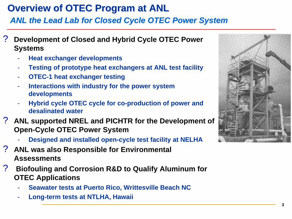
Overview of OTEC Program at ANLOverview of OTEC Program at ANLANLANL the Lead Lab for Closed Cycle OTEC Power Systemthe Lead Lab for Closed Cycle OTEC Power System
? Development of Closed and Hybrid Cycle OTEC Power Systems Heat exchanger developments Testing of prototype heat exchangers at ANL test facility OTEC-1 heat exchanger testing Interactions with industry for the power system
developments Hybrid cycle OTEC cycle for co-production of power and
desalinated water
? ANL supported NREL and PICHTR for the Development of Open-Cycle OTEC Power System Designed and installed open-cycle test facility at NELHA
? ANL was also Responsible for Environmental Assessments
? Biofouling and Corrosion R&D to Qualify Aluminum for OTEC Applications Seawater tests at Puerto Rico, Writtesville Beach NC Long-term tests at NTLHA, Hawaii
4
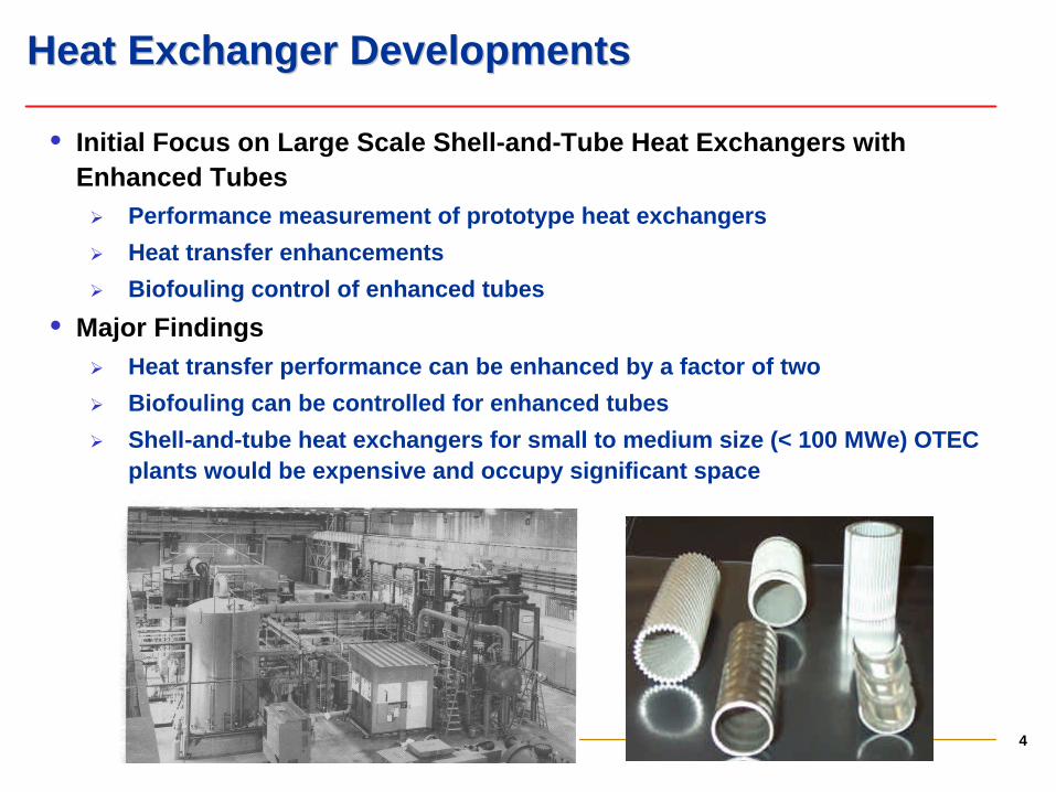
Heat Exchanger DevelopmentsHeat Exchanger Developments
• Initial Focus on Large Scale Shell-and-Tube Heat Exchangers with Enhanced TubesØ Performance measurement of prototype heat exchangers
Ø Heat transfer enhancements
Ø Biofouling control of enhanced tubes
• Major FindingsØ Heat transfer performance can be enhanced by a factor of two
Ø Biofouling can be controlled for enhanced tubes
Ø Shell-and-tube heat exchangers for small to medium size (< 100 MWe) OTEC plants would be expensive and occupy significant space
5
Heat Exchanger DevelopmentsHeat Exchanger Developments
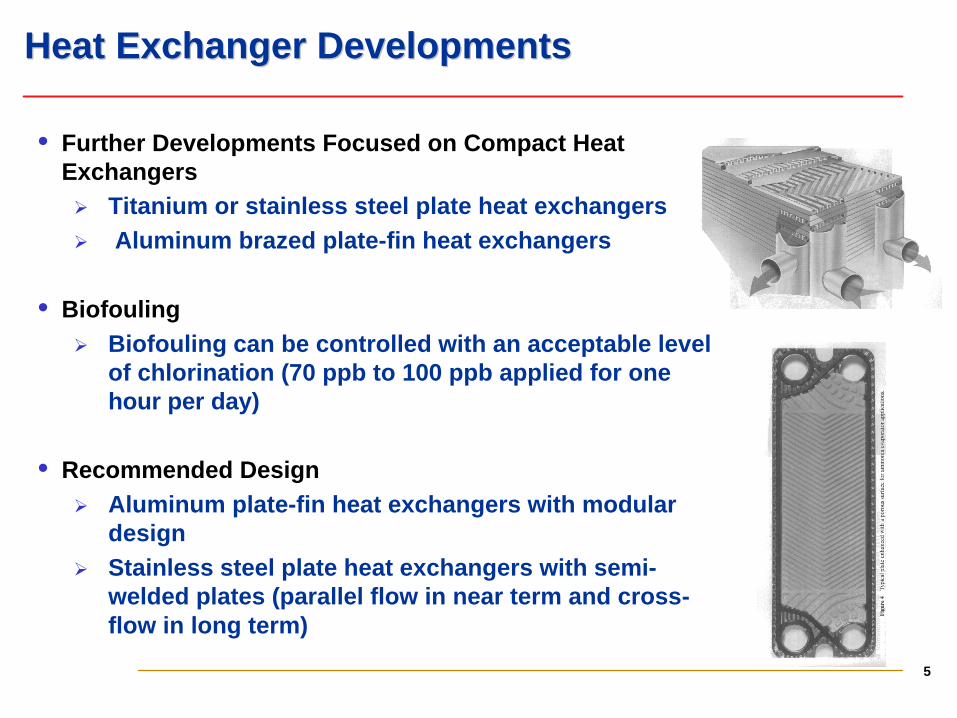
• Further Developments Focused on Compact Heat ExchangersØ Titanium or stainless steel plate heat exchangers Ø Aluminum brazed plate-fin heat exchangers
• BiofoulingØ Biofouling can be controlled with an acceptable level
of chlorination (70 ppb to 100 ppb applied for one hour per day)
• Recommended DesignØ Aluminum plate-fin heat exchangers with modular
designØ Stainless steel plate heat exchangers with semi-
welded plates (parallel flow in near term and cross-flow in long term)
6
Modular Aluminum Heat Exchangers Ideally Suited for Modular Aluminum Heat Exchangers Ideally Suited for OTEC Power SystemsOTEC Power Systems
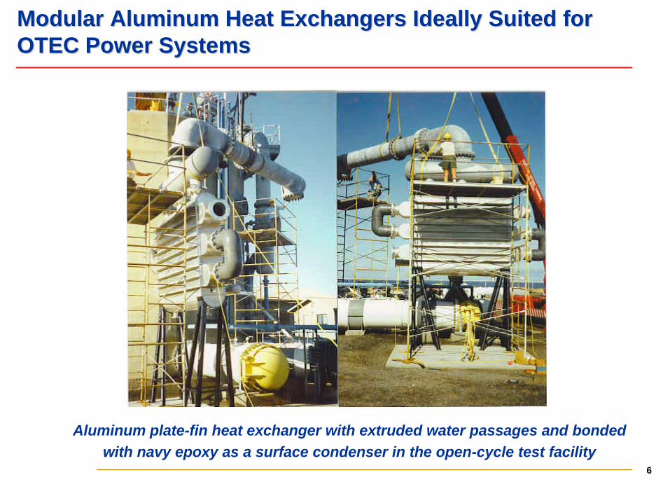
Aluminum plate-fin heat exchanger with extruded water passages and bonded with navy epoxy as a surface condenser in the open-cycle test facility
7
BiofoulingBiofouling and Corrosionand CorrosionUnique Unique LongLong--Term Experimental ProgramTerm Experimental Program
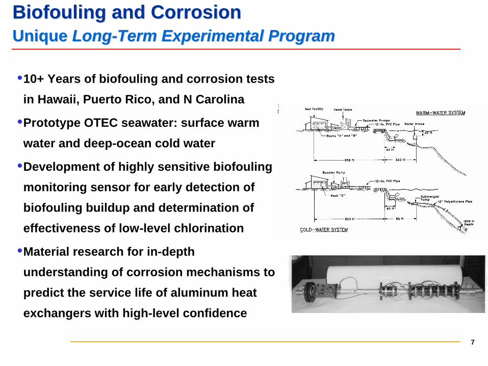
•10+ Years of biofouling and corrosion tests
in Hawaii, Puerto Rico, and N Carolina
•Prototype OTEC seawater: surface warm
water and deep-ocean cold water
•Development of highly sensitive biofouling
monitoring sensor for early detection of
biofouling buildup and determination of
effectiveness of low-level chlorination
•Material research for in-depth
understanding of corrosion mechanisms to
predict the service life of aluminum heat
exchangers with high-level confidence
8
BiofoulingBiofouling and Corrosionand CorrosionBiofoulingBiofouling Was a Major Technical BarrierWas a Major Technical Barrier
• No significant difference in biofouling behavior for aluminum alloys and
titanium or Al-6X stainless steel
• Warm water biofouling is controlled by 70 ppb to 100 ppb applied for
one hour per day
• Negligible biofouling is expected for deep-ocean cold water
• Biofouling of non-circular flow passages of plate-fin and plate heat
exchangers can be controlled like circular tubes
• Considering variability of biological parameters of seawater, it is
advisable to perform validation biofouling experiments (3 to 6 months)
at the proposed site in Puerto Rico
9
BiofoulingBiofouling and Corrosionand CorrosionQualification of Aluminum AlloysQualification of Aluminum Alloys
• 30 Year loss of metal is < 100 µm for warm water and < 200 µm for cold
water, both of which are less than acceptable level of 380 µm for 15+
service life
• Pitting corrosion not a major problem with a good design practice
• Use of aluminum alloys with seamless water flow passages can be
recommended for service life of 30 years with replacement/refurbishing of
modules after 15 years
Øwarm water has low risk
Øcold water does entail some risk and will require proper design and good
monitoring practice
• Infrequent brush cleaning is recommended to avoid local biofouling
buildup which may cause localized corrosion
10
Design Studies of OTEC PlantsDesign Studies of OTEC Plants
• Design Studies of 10 MWe Land-Based OTEC Plants
• Hybrid OTEC System for co-production of power and water
ØHybrid cycle with separate power and desalinations systems based
on commercial multi-stage flashing technology
ØIntegrated hybrid OTEC power system
• Review of 40 MWe Pilot OTEC Plants
• Man-made island based OTEC plant by Ocean Thermal Corporation
(OTC) and
• Tower-mounted OTEC plant by GE
11
Small LandSmall Land--Based OTEC PlantsBased OTEC Plants
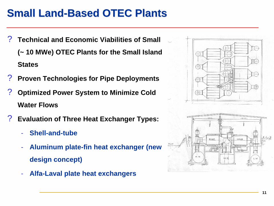
? Technical and Economic Viabilities of Small
(~ 10 MWe) OTEC Plants for the Small Island
States
? Proven Technologies for Pipe Deployments
? Optimized Power System to Minimize Cold
Water Flows
? Evaluation of Three Heat Exchanger Types:
Shell-and-tube
Aluminum plate-fin heat exchanger (new
design concept)
Alfa-Laval plate heat exchangers
12
Hybrid Cycle for CoHybrid Cycle for Co--Production of Electric Power and Fresh Production of Electric Power and Fresh WaterWater
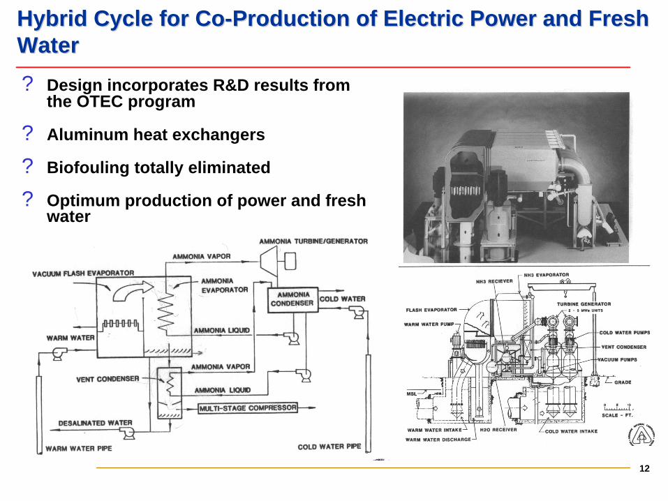
? Design incorporates R&D results from the OTEC program
? Aluminum heat exchangers
? Biofouling totally eliminated
? Optimum production of power and fresh water
13
OTEC OTEC PlantshipsPlantships for Cofor Co--Production of Ammonia and Production of Ammonia and Desalinated Water Desalinated Water
Ammonia as the hydrogen energy carrierØInfrastructure for distributing, storing and delivering hydrogen is non-
existent
ØExisting infrastructure for transporting, storing, and distributing ammonia
ØAmmonia has higher energy density (kWh/liter) than hydrogen
ØAmmonia being evaluated for distributed power generation and in IC
engines (particularly for farm equipment and irrigation pumps)
On-going DOE project at ArgonneØPhase I focuses on updating the Applied Physics Laboratory design of 40
MWe Pilot Plantship by incorporating plate-fin heat exchangers
ØPhase II focuses on co-production of ammonia, as the hydrogen carrier,
and desalinated water using hybrid cycle OTEC Plantship
14
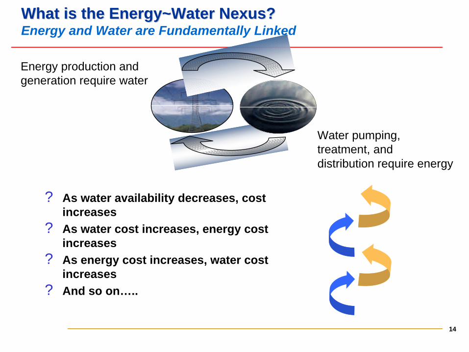
What is the Energy~Water Nexus?What is the Energy~Water Nexus?Energy and Water are Fundamentally Linked
Energy production and generation require water
Water pumping, treatment, anddistribution require energy
? As water availability decreases, cost increases
? As water cost increases, energy cost increases
? As energy cost increases, water cost increases
? And so on…..
15
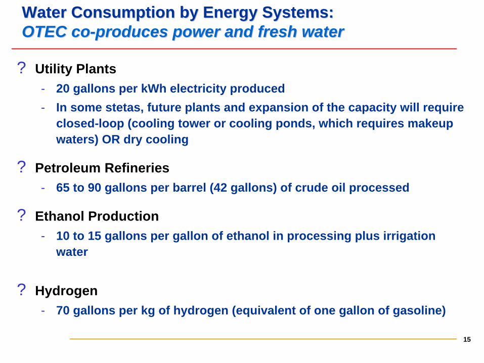
Water Consumption by Energy Systems:Water Consumption by Energy Systems:OTEC coOTEC co--produces power and fresh waterproduces power and fresh water
? Utility Plants 20 gallons per kWh electricity produced
In some stetas, future plants and expansion of the capacity will require closed-loop (cooling tower or cooling ponds, which requires makeup waters) OR dry cooling
? Petroleum Refineries 65 to 90 gallons per barrel (42 gallons) of crude oil processed
? Ethanol Production 10 to 15 gallons per gallon of ethanol in processing plus irrigation
water
? Hydrogen 70 gallons per kg of hydrogen (equivalent of one gallon of gasoline)
16
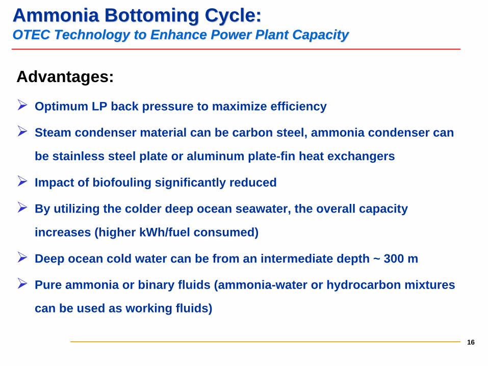
Ammonia Bottoming Cycle:Ammonia Bottoming Cycle:OTEC Technology to Enhance Power Plant CapacityOTEC Technology to Enhance Power Plant Capacity
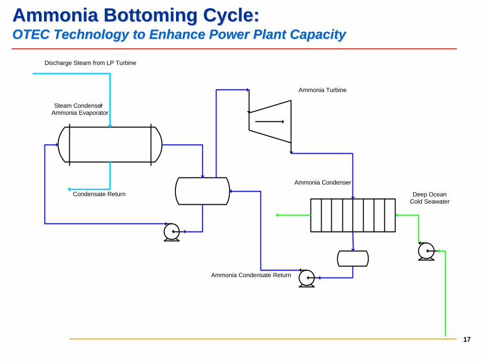
Advantages:
Ø Optimum LP back pressure to maximize efficiency
Ø Steam condenser material can be carbon steel, ammonia condenser can
be stainless steel plate or aluminum plate-fin heat exchangers
Ø Impact of biofouling significantly reduced
Ø By utilizing the colder deep ocean seawater, the overall capacity
increases (higher kWh/fuel consumed)
Ø Deep ocean cold water can be from an intermediate depth ~ 300 m
Ø Pure ammonia or binary fluids (ammonia-water or hydrocarbon mixtures
can be used as working fluids)
17
Ammonia Bottoming Cycle:Ammonia Bottoming Cycle:OTEC Technology to Enhance Power Plant CapacityOTEC Technology to Enhance Power Plant Capacity
Steam Condenser/Ammonia Evaporator
Ammonia Turbine
Ammonia Condenser
Discharge Steam from LP Turbine
Condensate Return
Ammonia Condensate Return
Deep Ocean Cold Seawater
18
Path ForwardPath Forward
Ø Established technology base of the OTEC Power System for the first
generation of commercial OTEC plants with guaranteed power system
performance
Ø Further improvements of the power system will improved performance
and cost reduction
Ø Co-production of desalinated water will significantly improve the
economics of OTEC plants for near-term commercialization
Ø In many respects year 2030 has been set for alternate enenrgy supply;
therefore, there is a window of opportunity to commercialize OTEC
19
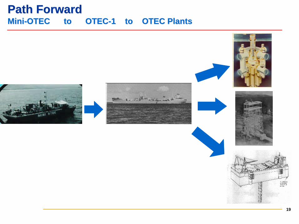
Path ForwardPath ForwardMiniMini--OTEC to OTECOTEC to OTEC--1 to OTEC Plants1 to OTEC Plants
Recommended