Broadband over Power Line (BPL) Test Broadband over Power Line (BPL) Test Procedures and Equipment Procedures and Equipment
AuthorizationAuthorization
Andy Andy LeimerLeimerEquipment Authorization BranchEquipment Authorization Branch
Federal Communications CommissionOffice of Engineering and Technology
Laboratory Division
February 2005 TCB Workshop 2
BPL and Carrier Current System (CCS)BPL and Carrier Current System (CCS)Existing Rule ReviewExisting Rule Review
BPL devices are “carrier current systems” [15.3(f)] – BPL is a Subset of CCSPart 15 interference requirements– Must not cause harmful interference - Any
emission, radiation or induction that endangers the functioning of a radio navigation service or of other safety services or seriously degrades, obstructs or repeatedly interrupts a radiocommunicationsservice operating in accordance with this Chapter. [15.3(m)]
– Must accept interference from other devices
February 2005 TCB Workshop 3
BPL and Carrier Current System (CCS)BPL and Carrier Current System (CCS)Existing Rule Review (Existing Rule Review (Con’tCon’t))
Emission limits– AC-Line Conducted limits [15.107]
• Devices operating < 30 MHz: 1000 uV in 535 –1705 MHz
• Devices operating > 30 MHz: Same as digital device limits (150 kHz – 30 MHz)
– Radiated limits • < 30 MHz Intentional radiator limits [15.209]
– 1.705-30 MHz: 30 uV/m at 30 m)• > 30 MHz Unintentional radiator limits [15.109]
Class A and Class B LimitsField strength measurements are “in situ”– Three representative installations
February 2005 TCB Workshop 4
Access BPL ScopeAccess BPL ScopeIn-house BPL– No change to existing rules– New measurement guidelines
Access BPLDefinition: A carrier current system that transmits radio
frequency energy by conduction over electric power lines owned, operated, or controlled by an electric service provider. The electric power lines may be aerial (overhead) or underground
February 2005 TCB Workshop 5
Access BPL Scope (Access BPL Scope (Con’tCon’t))
Existing rules remain in place– Conducted limits do not apply to
Access BPL– Class B radiated limits apply to low-
voltage “drop” linesNew rules added to support interference mitigationNew measurement guidelines for BPL and CCS
February 2005 TCB Workshop 6
BPL Report and Order (R&O)BPL Report and Order (R&O)R&O (FCC 04-245)– Rules published in the Federal Register
January 7,2005– New Subpart G
http://hraunfoss.fcc.gov/edocs_public/attachmatch/FCC-04-245A1.pdfTransition Provisions– New equipment must comply 18 months after publication in
the Federal Register– Existing equipment may operate for duration of useful life if
there are no reported instances of harmful interference
ErratumDOC-254180A1.doc
February 2005 TCB Workshop 7
New Access BPL RulesNew Access BPL RulesCertification required for Access BPLAccess BPL must include adaptive interference mitigation capabilities to avoid local and site-specific interference– Exclude or “notch” any specific frequency or band– Remotely shut off any BPL device
Excluded Bands– 12 Aeronautical frequencies
Exclusion zones – frequencies prohibited based on distance– US Coast Guard or maritime coast stations– Radio astronomy
February 2005 TCB Workshop 8
New Access BPL Rules (New Access BPL Rules (Con’tCon’t))Establishes “consultative requirements” for BPL with public safety, and certain sensitive federal and aeronautical stationsEstablishes a “good faith” process to ensure that– Access BPL systems do not cause interference– Any BPL restrictions by licensees are only those
necessary to avoid interferenceIndustry to establish a public accessible database deployment informationInterference complaint procedures
February 2005 TCB Workshop 9
BPL General InformationBPL General InformationAccess BPL - EUT defined as device (not system) requiring Certification– May include the electronic equipment enclosure,
coupling device, and medium voltage lines that are injected (Phase and neutral if both are injected), including the power line(s) to which the device couples
– Pole ground wires not considered to be part of EUT
All BPL system components require separate certification.Currently, TCBs cannot authorize Access BPL devices
February 2005 TCB Workshop 10
Operational DescriptionOperational DescriptionDescribe device function – injectors, extractors, repeaters, boosters, concentrators, couplers, etc.Describe BPL coupling of the medium voltage line (if applicable) distribution to customer premises (coupled around low voltage transformer, directly through the low voltage transformer, IEEE 802.11, other)Frequency range(s), BW, Modulation, variable power setting, notch filtering, duty factor, data rates, etc.Configuration – setup and control, signal routing, how is device used in a BPL systemNotch Capabilities – frequencies, 20dB BW, control, cold power-up defaults
February 2005 TCB Workshop 11
Test Site Selection Test Site Selection In-Situ Testing (Part 15.31(d))– three typical overhead line installations and three typical underground line installations.Overhead Line - unobstructed access to:– Pole containing electronic enclosure and couplers – Medium voltage lines for distance of 1 wavelength (mid-
band) at a minimum 10m horizontal distance from the power line
Underground Line – select transformer or BPL equipment box away from cable TV and telephone utility connection boxes– Power company layout map helpful to locate the location of
the underground wiring
February 2005 TCB Workshop 12
Test Site Selection (Con’t.)Test Site Selection (Con’t.)
Avoid the following if possible:– Splits in overhead lines– Risers that connect to underground lines
Noisy lines can result in inconclusive QP measurements
February 2005 TCB Workshop 13
Determining Maximum Emissions Determining Maximum Emissions to be Testedto be Tested
Peak emissions across the bandPower average (100 sweeps) reduces the effects of ambients and noise - recommended9 kHz RBW < 30 MHz and 100 kHz RBW > 30 MHzAntenna selection– Active Loop < 30 MHz
• Increases measurement S/N ratio• Greater risk of overload due to AM broadcast stations• Greater frequency range without switch setting
– Passive Loop < 30 MHz• Less risk of overload• Can use external pre-selection filtering directly on the
antenna
February 2005 TCB Workshop 14
Determining Maximum Emissions Determining Maximum Emissions to be Tested (to be Tested (Con’tCon’t.).)
Bicon > 30 MHzExternal Amplifiers – engineering judgmentLow-pass and high-pass filters recommended to reduce AM/FM & TV broadcast band effects
February 2005 TCB Workshop 15
Radiated Emissions TestingRadiated Emissions TestingSignificant medium voltage line emissions seen as a – Measure at a 10m horizontal distance from the line, if
Ensure that maximum or near-maximum RF injection – Use maximum data rate available. This can be configured by – Data communications must result in at least 20 Hz minimum
February 2005 TCB Workshop 16
Radiated Emissions Testing (Con’t.)Radiated Emissions Testing (Con’t.)
Test at 0, 1/4,1/2, 3/4, and 1 wavelength down the – Slant range distance up to 30m
• Overhead line distance correction based on Slant Range – Recommended minimum horizontal distance from pole or – Loop antennas: 1m antenna height, maximized from parallel – Bicon antennas: Scan from 1 to 4m antenna height, H & V
• Alternative procedure – measure at 1m antenna height
February 2005 TCB Workshop 17
Slant Range DistanceSlant Range Distance
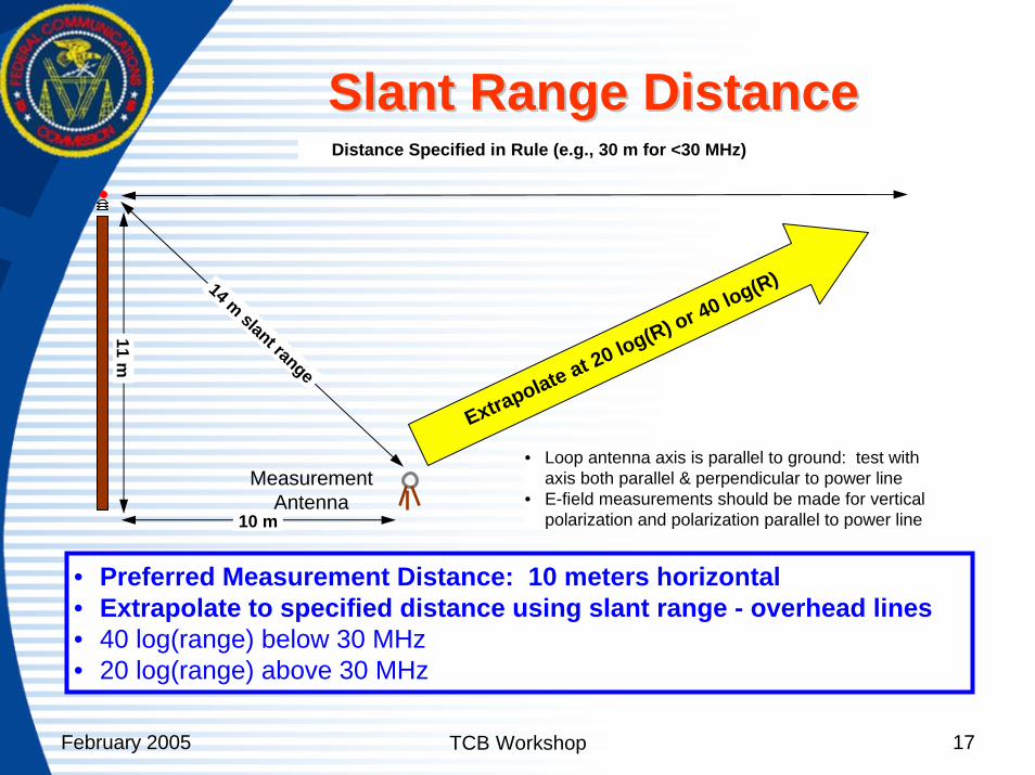
10 m
11 m
MeasurementAntenna
14 m slant range
Distance Specified in Rule (e.g., 30 m for <30 MHz)
• Preferred Measurement Distance: 10 meters horizontal• Extrapolate to specified distance using slant range - overhead lines• 40 log(range) below 30 MHz• 20 log(range) above 30 MHz
Extrapolate at 20 log(R) or 40 log(R)
• Loop antenna axis is parallel to ground: test with axis both parallel & perpendicular to power line
• E-field measurements should be made for vertical polarization and polarization parallel to power line
February 2005 TCB Workshop 18
Radiated Emissions Testing (Con’t.)Radiated Emissions Testing (Con’t.)Antenna orientation and position for underground installations:– 16 radials – Loop antennas: 1m antenna height, maximized
from parallel to line to +/-90 degrees (perpendicular to line)
– Bicon antennas: 1 to 4m antenna height, H & V polarization
Maximize the signals in accordance to ANSII C63.4 – explain the test procedure in detail and report the worst case emissions
February 2005 TCB Workshop 19
Radiated Emissions Testing (Con’t.)Radiated Emissions Testing (Con’t.)QP measurements:– Maximize the BPL data rate for uplink and
downlink– Maximum six discrete frequencies across the
band (Recommended for non-digitizing analyzers). Zero span measurements recommended for older analyzers.
– Sweep the band that includes the maximum emissions (Note: maximum 50 kHz sweeps for QP measurements < 30 kHz (9kHz RBW))
The measurement procedures for medium voltage lines and low voltage lines are identical. Medium and low voltage lines (if applicable) must both be tested.
February 2005 TCB Workshop 20
Access BPL Equipment Access BPL Equipment Authorization Authorization -- Additional ItemsAdditional Items
FCC ID Label– Font size TBD
User’s Manual– Device not marketed to public– An Installation Manual is required– Specify settings and control for operation in
compliance with the RulesNotch capability– Test procedure not addressed in R&O– Manufacturer’s compliance statement required
February 2005 TCB Workshop 21
InIn--House BPL ModemHouse BPL ModemEquipment AuthorizationEquipment Authorization
CCS requiring Verification• In-situ testing - three test sites• Test at 3 positions along overhead power service
line to house
Class B Computer Peripheral (JPB)• DoC or Certification (Section 15.101)• Table top testing – radiated and conducted
emissions
February 2005 TCB Workshop 22
Thanks!Thanks!Thanks!
Recommended