Performance Analysis of Power Line Communication Using DS-CDMA Technique with Adaptive Laguerre Filters
S. Liewkang and C. Banjangkaprasert +
Faculty of Engineering, King Mongkut’s Institute of Technology Ladkrabang, Bangkok 10520, Thailand E-mail : [email protected], [email protected]
Abstract. This paper presents the system performance of the power line communication (PLC) using direct-sequence code division multiple access (DS-CDMA) technique with an adaptive equalizer based on Laguerre filter. The objectives are to improve the performance of system by means of bit error rate (BER) at the receiver, and to eliminate the effect of noise disturbance due to additive white Gaussian noise (AWGN), impulse noise and multipath fading in the power line channel. Our simulation results show that the proposed receiver performs lower BER than the conventional FIR filter receiver.
Keywords: PLC, DS-CDMA system, Adaptive Laguerre filter.
1. Introduction As a result of recent developments, the electrical power supply system is on the way to migrate from a
pure energy distribution network to a multipurpose medium delivering energy, voice, and various data services. In particular, Internet access is currently in the focus of the efforts of various research activities [1]. There are limits in transfer power line systems[1-5] which are in part due to some difficulties found when sending the data system. Some examples of these difficulties include impedance value (change all the time), interference signal in the power line system, attenuation that has a high value. A simple approach to rough estimation of the transfer function of power line channels was presented in [2]. A straight line can interpolate the attenuation increasing with higher frequencies, so a simple equation can be found to calculate the amplitude of the channel transfer function. As this approach does not consider multipath propagation and the resulting notches of the channel transfer function, more detailed models had to be developed. Multipath propagation approaches, which are suitable for describing the transmission behaviour of power line channels, have been proposed in [3] and [4].
Direct sequence code division multiple access (DS-CDMA)[6] is a candidate access technique for a third generation mobile system. In DS-CDMA system, signal transmission over time-varying multipath mobile radio channel produces intersymbol interference (ISI) and other time-varying effect from the channel. Adaptive equalizers are generally required to mitigate the effect of the channel.
Laguerre filter[7], sharing the characteristic of finite impulse response (FIR) filter and infinite impulse response (IIR) filter, represents a compromise between computational complexity and stability.
The recursive least squares (RLS) algorithm is the one of the most popular algorithm for the adaptive filter application [7-10]. The main feature of RLS algorithm is its fast convergence rate, especially for highly correlated input signal. Therefore, in this paper interests the RLS algorithm for the proposed equalizer.
In this paper the performance of the power line communication using direct-sequence code division multiple access(DS-CDMA) technique with adaptive Laguerre equalizer is presented. The objective of this paper is to increase potential and decrease bit error rate, which occurs from interference of the signal in power line systems.
+ Corresponding author. Tel.: + 6623298329; fax: +6623298327. E-mail address: [email protected]
2011 International Conference on Information and Electronics Engineering IPCSIT vol.6 (2011) © (2011) IACSIT Press, Singapore
50
0
sTdt∫( )r t
( )ks t
kykb
1a1ib
1s
2a2ib
2s
kaikb
ks
∑ ( , )H f t
( )n t
( )r t
2. Multipath Model for Power Line Channel The echo model describes the channel impulse response as a superposition of N direct pulses
representing the superposition of signals from N different paths. Each of these impulses is multiplied by a complex factor iρ and delayed by time iτ . The factors iρ represent the product of reflection and transmission factors along each echo path. The complex channel transfer function is given as [3]
2
1( ) i
Nj f
ii
H f e π τρ −
=
=∑ (1)
This model allows realistic reproduction of notches of the channel transfer function and is therefore well suited to describe indoor channels where the low-pass characteristic of the channel is not relevant.
In [4] describes a universal and practically useful form of the complex transfer function for power line channels by an adapted echo model that contains an additional attenuation factor. This model represents the superposition of signals from N different paths, each of which is individually characterized by a weighting factor ig and length id . Furthermore, frequency-dependent attenuation is modeled by the parameters 0a , 1a , and k. Then, the useful form of the complex transfer function for power line channels can be expressed as
0 12
( )
1( )
ik
pi
dN j fva a f d
ii
H f g e eπ−
− +
=
=∑ (2)
While the first exponential function describes attenuation, the second one, including the propagation speed pv , represents the echo scenario. The parameters for the multipath model can be obtained from measurements of the complex channel transfer function. The attenuation parameters 0a (offset of attenuation), 1a (increase of attenuation), and k (exponent of attenuation) can be obtained from the magnitude of the frequency response. To determine the path parameters id and ig , the impulse response is necessary. The impulse response gives information about the time delay of each path, which is proportional to id . The weighting factors ig can be obtained from the amplitude of each impulse.
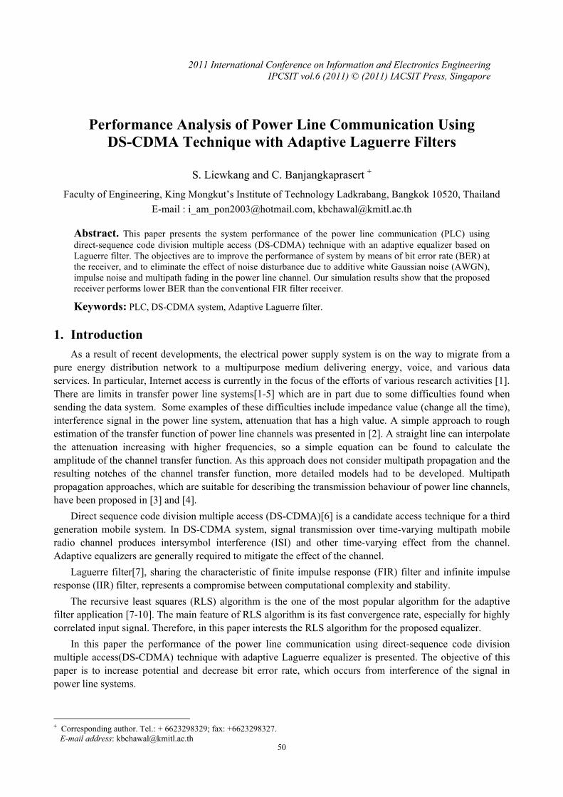
3. Direct Sequence Code Division Multiple Access(DS-CDMA) DS-CDMA is the method that allows the data signal to directly modulate with digital signal. The data
signal can be achieved in both an analog and digital signals. The data signal will multiply the code signal directly and then bring the signal to modulate with the carrier signal. This paper will consider the data transfer through power line channels by the DS-CDMA system, which has the following model.
Fig. 1 Transmitter model. Fig. 2 Receiver model.
In consideration of the data transfer model in the DS-CDMA system through power line channel, which has noise in white Gaussian noise, and assign users in the system for k user, i
kb is a data bit at i of user k (which has sT time period of signal), ka is size of acceptable signal from receiver k , ks is spread code of user k , which has chip equal to cL , allows the following formula to be formed :
1
0( ) ( ) ( )
cL
k i ci
s i s i x t iT−
=
= −∑ (3)
A formula showing the collective signal from the receiver can be written as follows:
0 1( ) ( )* ( ) ( )
Ki ik k s
i kr t a b s t iT h t n t
∞
= =
= − +∑∑ (4)
51
Receivers in DS-CDMA system’s duty is separate to each user, where the users’ receiver including despread code of each user and integration circuit can be shown in the Fig. 2.
We observed that each user’s receiver using only the own spread data in separate wanted signal then bring the signal past to bit decision circuit in order to get the designed data. If ky is outcome signal from user k ’s receiver at siT , we can write the following formula:
0
( ) ( )sT
k ky r t s t dt= ∫ (5)
Finally, the decision output of the detector can be defined as sgn( )k kb y= (6)
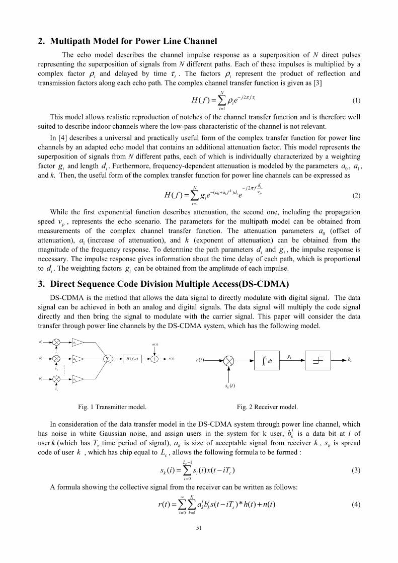
4. Adaptive Laguerre Equalizer Adaptive equalizer is the main required for the system to achieve high performance of the
communication. Therefore, in this section we will briefly describe the structure of the equalizer and followed by the usefulness adaptive algorithm.
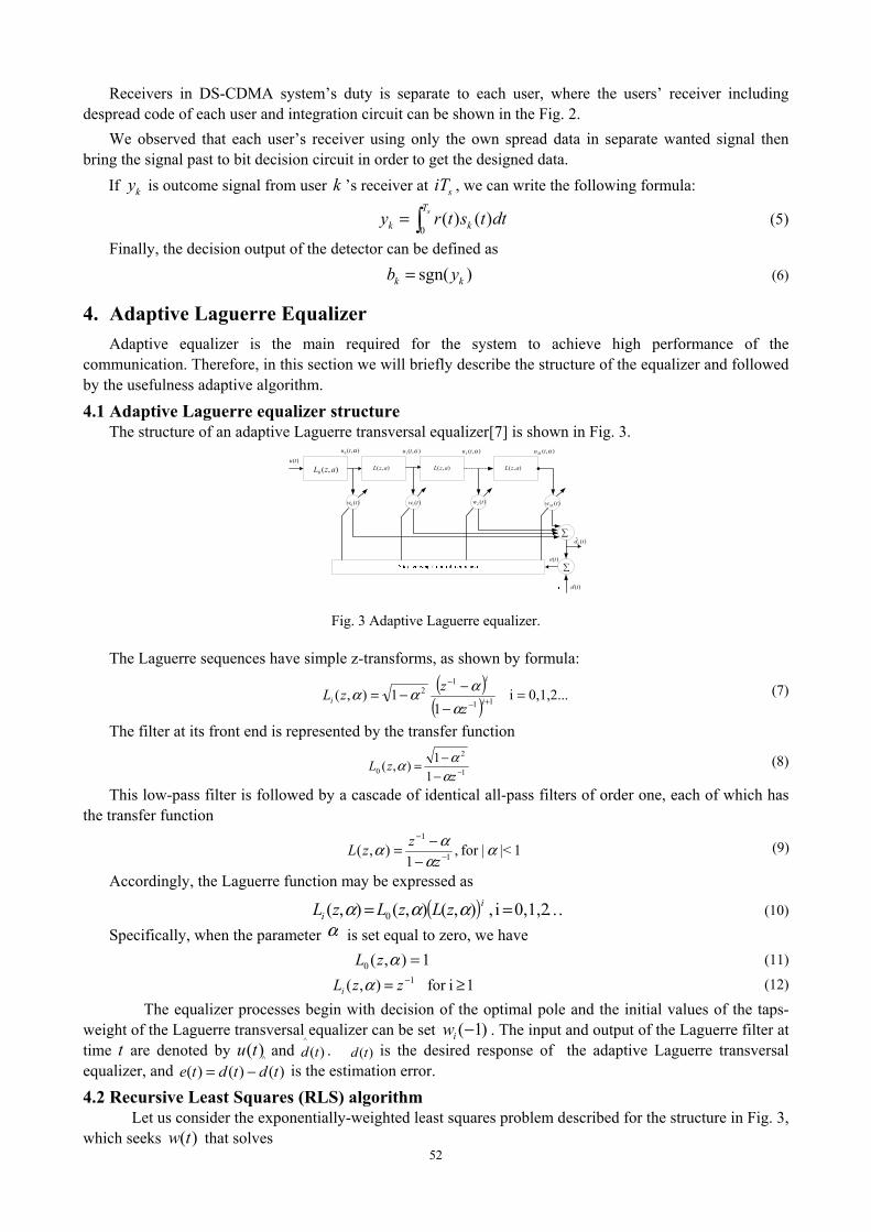
4.1 Adaptive Laguerre equalizer structure The structure of an adaptive Laguerre transversal equalizer[7] is shown in Fig. 3.
)(twM)(0 tw )(1 tw )(2 tw
∑
),( azL),(0 azL ),( azL ),( azL
∑)(te
)(ˆ tdk
)(td
)(tu),(0 αtu ),( αtuM),(2 αtu),(1 αtu
Fig. 3 Adaptive Laguerre equalizer.
The Laguerre sequences have simple z-transforms, as shown by formula:
( )( ) 0,1,2...i1
1),( 11
12 =
−−−= +−
−
i
i
iz
zzLα
ααα (7)
The filter at its front end is represented by the transfer function
1
2
0 11),( −−
−=z
zLα
αα (8)
This low-pass filter is followed by a cascade of identical all-pass filters of order one, each of which has the transfer function
1|< |for ,1
),( 1
1
αα
αα −
−
−−=z
zzL (9)
Accordingly, the Laguerre function may be expressed as
( ) …== 0,1,2i , ),(),(),( 0i
i zLzLzL ααα (10)
Specifically, when the parameter α is set equal to zero, we have 1),(0 =αzL (11)
1 ifor ),( 1 ≥= −zzLi α (12)
The equalizer processes begin with decision of the optimal pole and the initial values of the taps-weight of the Laguerre transversal equalizer can be set )1(−iw . The input and output of the Laguerre filter at time t are denoted by )(tu and )(
^td . )(td is the desired response of the adaptive Laguerre transversal
equalizer, and )()()(^
tdtdte −= is the estimation error.
4.2 Recursive Least Squares (RLS) algorithm Let us consider the exponentially-weighted least squares problem described for the structure in Fig. 3,
which seeks )(tw that solves 52
2
1
1 |)(|J(t) iet
i
t∑=
−= λ (13)
The squared error can be define as )()1()()( tutwtdte −−= (14)
and the update equation of the adaptive RLS algorithm is given as follows [7]:
)()1()(
)()1()(tutPtu
tutPtk T
T
−+−=
λ (15)
[ ])1()()()1(1)( −−−= tPtutktPtPλ
(16)
)()()1()( tetktwtw ∗+−= (17)
where IP 1)1( −=− δ and δ is small positive constant, I is identity matrix and the forgetting factor 10 << λ , which is usually chosen in the range of 19.0 << λ .
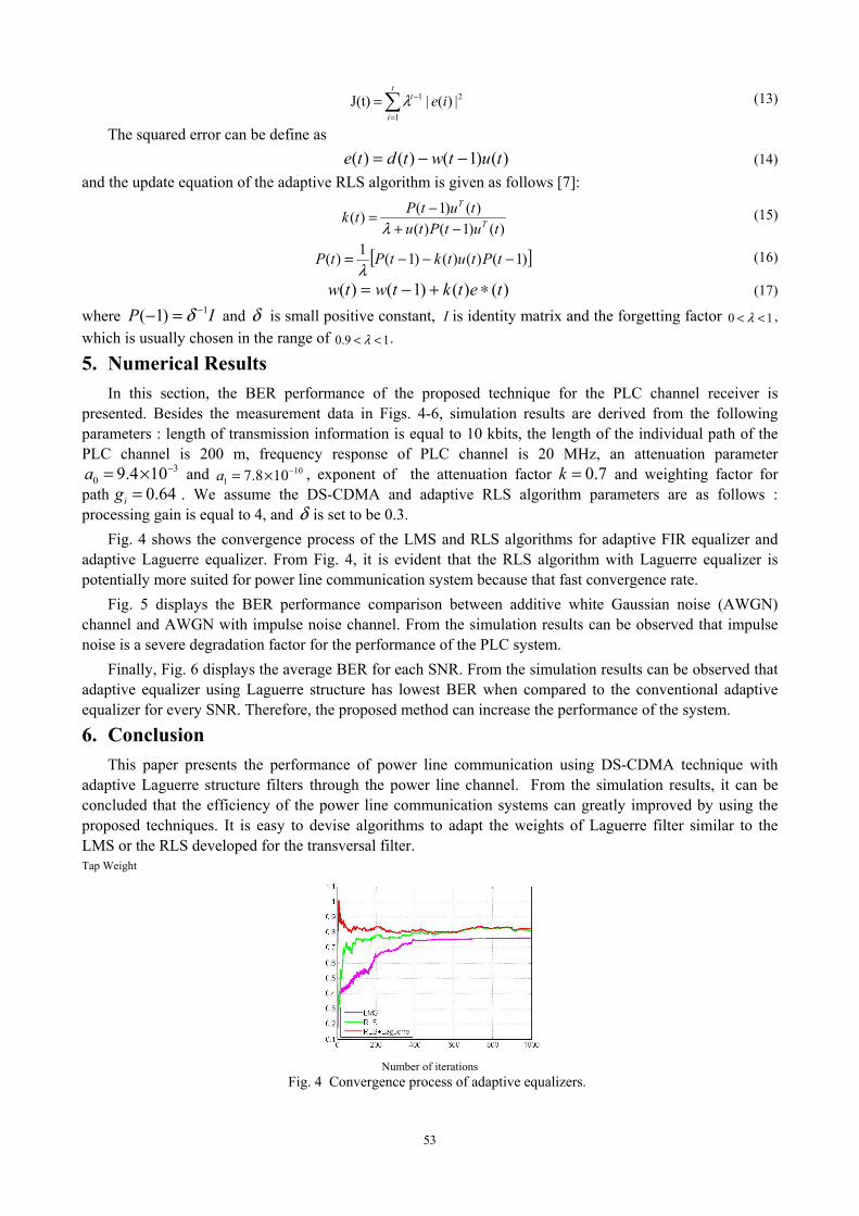
5. Numerical Results In this section, the BER performance of the proposed technique for the PLC channel receiver is
presented. Besides the measurement data in Figs. 4-6, simulation results are derived from the following parameters : length of transmission information is equal to 10 kbits, the length of the individual path of the PLC channel is 200 m, frequency response of PLC channel is 20 MHz, an attenuation parameter
30 9.4 10a −= × and 10
1 7.8 10a −= × , exponent of the attenuation factor 0.7k = and weighting factor for path 0.64ig = . We assume the DS-CDMA and adaptive RLS algorithm parameters are as follows : processing gain is equal to 4, and δ is set to be 0.3.
Fig. 4 shows the convergence process of the LMS and RLS algorithms for adaptive FIR equalizer and adaptive Laguerre equalizer. From Fig. 4, it is evident that the RLS algorithm with Laguerre equalizer is potentially more suited for power line communication system because that fast convergence rate.
Fig. 5 displays the BER performance comparison between additive white Gaussian noise (AWGN) channel and AWGN with impulse noise channel. From the simulation results can be observed that impulse noise is a severe degradation factor for the performance of the PLC system.
Finally, Fig. 6 displays the average BER for each SNR. From the simulation results can be observed that adaptive equalizer using Laguerre structure has lowest BER when compared to the conventional adaptive equalizer for every SNR. Therefore, the proposed method can increase the performance of the system.
6. Conclusion This paper presents the performance of power line communication using DS-CDMA technique with
adaptive Laguerre structure filters through the power line channel. From the simulation results, it can be concluded that the efficiency of the power line communication systems can greatly improved by using the proposed techniques. It is easy to devise algorithms to adapt the weights of Laguerre filter similar to the LMS or the RLS developed for the transversal filter. Tap Weight
Number of iterations
Fig. 4 Convergence process of adaptive equalizers.
53
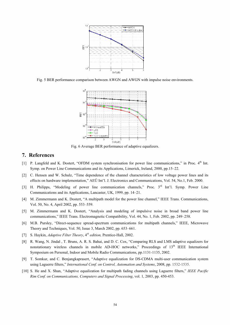
Fig. 5 BER performance comparison between AWGN and AWGN with impulse noise environments.
Fig. 6 Average BER performance of adaptive equalizers.
7. References [1] P. Langfeld and K. Dostert, “OFDM system synchronisation for power line communications,” in Proc. 4th Int.
Symp. on Power Line Communications and its Applications, Limerick, Ireland, 2000, pp.15–22.
[2] C. Hensen and W. Schulz, “Time dependence of the channel characteristics of low voltage power lines and its effects on hardware implementation,” AEÜ Int’l. J. Electronics and Communications, Vol. 54, No.1, Feb. 2000.
[3] H. Philipps, “Modeling of power line communication channels,” Proc. 3rd Int’l. Symp. Power Line Communications and its Applications, Lancaster, UK, 1999, pp. 14–21.
[4] M. Zimmermann and K. Dostert, “A multipath model for the power line channel,” IEEE Trans. Communications, Vol. 50, No. 4, April 2002, pp. 553–559.
[5] M. Zimmermann and K. Dostert, “Analysis and modeling of impulsive noise in broad band power line communications,” IEEE Trans. Electromagnetic Compatibility, Vol. 44, No. 1, Feb. 2002, pp. 249–258.
[6] M.B. Pursley, “Direct-sequence spread-spectrum communications for multipath channels,” IEEE, Microwave Theory and Techniques, Vol. 50, Issue 3, March 2002, pp. 653–661.
[7] S. Haykin, Adaptive Filter Theory, 4th edition, Prentice-Hall, 2002.
[8] R. Wang, N. Jindal , T. Bruns, A. R. S. Bahai, and D. C. Cox, “Comparing RLS and LMS adaptive equalizers for nonstationary wireless channels in mobile AD-HOC networks,” Proceedings of 13th IEEE International Symposium on Personal, Indoor and Mobile Radio Communications, pp.1131-1135, 2002.
[9] T. Somkur, and C. Benjangkaprasert, “Adaptive equalization for DS-CDMA multi-user communication system using Laguerre filters,” International Conf. on Control, Automation and Systems, 2008, pp. 1532-1535.
[10] S. He and X. Shan, “Adaptive equalization for multipath fading channels using Laguerre filters,” IEEE Pacific Rim Conf. on Communications, Computers and Signal Processing, vol. 1, 2003, pp. 450-453.
54
Recommended