Phase I Stormwater Best Management Practices Implementation Plan
Prepared for
Boston Water and Sewer Commission
May 2013
18 Tremont Street
Suite 700 Boston, MA 02108

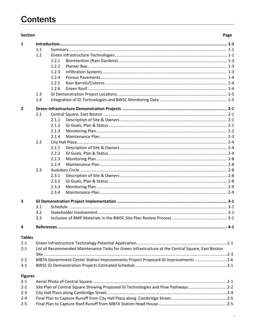
Contents Section Page
I
1 Introduction ......................................................................................................................................... 1‐1 1.1 Summary .......................................................................................................................................... 1‐1 1.2 Green Infrastructure Technologies .................................................................................................. 1‐1
1.2.1 Bioretention (Rain Gardens) ............................................................................................... 1‐3 1.2.2 Planter Box .......................................................................................................................... 1‐3 1.2.3 Infiltration Systems ............................................................................................................. 1‐3 1.2.4 Porous Pavements .............................................................................................................. 1‐4 1.2.5 Rain Barrels/Cisterns .......................................................................................................... 1‐4 1.2.6 Green Roof .......................................................................................................................... 1‐4
1.3 GI Demonstration Project Locations ................................................................................................ 1‐5 1.4 Integration of GI Technologies and BWSC Monitoring Data ........................................................... 1‐5
2 Green Infrastructure Demonstration Projects ...................................................................................... 2‐1 2.1 Central Square, East Boston ............................................................................................................ 2‐1
2.1.1 Description of Site & Owners ............................................................................................. 2‐1 2.1.2 GI Goals, Plan & Status ....................................................................................................... 2‐1 2.1.3 Monitoring Plan .................................................................................................................. 2‐2 2.1.4 Maintenance Plan ............................................................................................................... 2‐3
2.2 City Hall Plaza ................................................................................................................................... 2‐4 2.2.1 Description of Site & Owners ............................................................................................. 2‐4 2.2.2 GI Goals, Plan & Status ....................................................................................................... 2‐4 2.2.3 Monitoring Plan .................................................................................................................. 2‐8 2.2.4 Maintenance Plan ............................................................................................................... 2‐8
2.3 Audubon Circle ................................................................................................................................ 2‐8 2.3.1 Description of Site & Owners ............................................................................................. 2‐8 2.3.2 GI Goals, Plan & Status ....................................................................................................... 2‐8 2.3.3 Monitoring Plan .................................................................................................................. 2‐9 2.3.4 Maintenance Plan ............................................................................................................... 2‐9
3 GI Demonstration Project Implementation .......................................................................................... 3‐1 3.1 Schedule .......................................................................................................................................... 3‐1 3.2 Stakeholder Involvement ................................................................................................................. 3‐1 3.3 Inclusion of BMP Materials in the BWSC Site Plan Review Process ................................................ 3‐1
4 References ........................................................................................................................................... 4‐1
Tables 1‐1 Green Infrastructure Technology Potential Application ............................................................................... 1‐1 2‐1 List of Recommended Maintenance Tasks for Green Infrastructure at the Central Square, East Boston
Site ................................................................................................................................................................ 2‐3 2‐2 MBTA Government Center Station Improvements Project Proposed GI Improvements ............................ 2‐6 3‐1 BWSC GI Demonstration Projects Estimated Schedule ................................................................................ 3‐1
Figures 2‐1 Aerial Photo of Central Square ..................................................................................................................... 2‐1 2‐2 Site Plan of Central Square Showing Proposed GI Technologies and Flow Pathways .................................. 2‐2 2‐3 City Hall Plaza along Cambridge Street. ........................................................................................................ 2‐4 2‐4 Final Plan to Capture Runoff from City Hall Plaza along Cambridge Street ................................................. 2‐5 2‐5 Final Plan to Capture Roof Runoff from MBTA Station Head House ............................................................ 2‐5

CONTENTS, CONTINUED
II
2‐6 Approximate Drainage Area Managed by Proposed GI Technologies ......................................................... 2‐7 2‐7 Audubon Circle Project Location at Intersection of Beacon Street and Park Drive ..................................... 2‐8 2‐8 Approximate Drainage Area Managed by Proposed GI Technologies ......................................................... 2‐9
Acronyms and Abbreviations
III
ADA Americans with Disabilities Act
BMP best management practice
BTD Boston Transportation Department
BPW Boston Public Works Department
BRA Boston Redevelopment Authority
BWSC Boston Water and Sewer Commission
CFS cubic foot per second
GI green infrastructure
GSI green stormwater infrastructure
LID low impact development
MBTA Massachusetts Bay Transportation Authority
Parks Boston Parks and Recreation Department
TMDL total maximum daily load
USEPA United States Environmental Protection Agency

1-1
SECTION 1
Introduction 1.1 Summary The purpose of this report is to document the Boston Water and Sewer Commission’s (BWSC) proposed stormwater best management practices (BMPs), also referred to as green infrastructure (GI) technologies, for implementation as demonstration projects within the City of Boston pursuant to Section VII, Part D, Paragraph 26 of the Consent Decree. BWSC has identified three demonstration projects, as outlined in Paragraph 26 as Central Square in East Boston, City Hall Plaza, and Audubon Circle, in which the BWSC plans to implement and evaluate GI for runoff reduction and water quality improvements. This plan includes recommendations and schedules for the implementation of specific GI/low impact development (LID) BMPs for each site. The BMPs proposed are tailored to monitoring data collected by the BWSC and will, in addition to addressing pollutant discharges, bolster the BWSC’s stakeholder involvement and public education efforts.
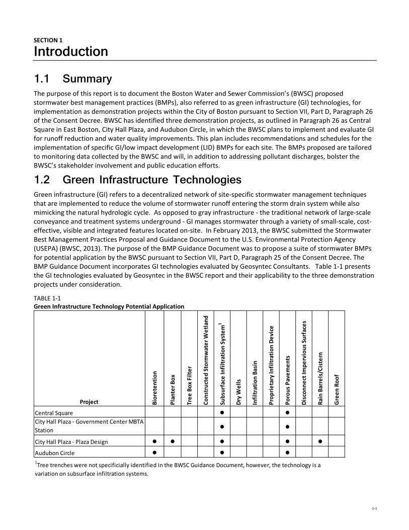
1.2 Green Infrastructure Technologies Green infrastructure (GI) refers to a decentralized network of site‐specific stormwater management techniques that are implemented to reduce the volume of stormwater runoff entering the storm drain system while also mimicking the natural hydrologic cycle. As opposed to gray infrastructure ‐ the traditional network of large‐scale conveyance and treatment systems underground ‐ GI manages stormwater through a variety of small‐scale, cost‐effective, visible and integrated features located on‐site. In February 2013, the BWSC submitted the Stormwater Best Management Practices Proposal and Guidance Document to the U.S. Environmental Protection Agency (USEPA) (BWSC, 2013). The purpose of the BMP Guidance Document was to propose a suite of stormwater BMPs for potential application by the BWSC pursuant to Section VII, Part D, Paragraph 25 of the Consent Decree. The BMP Guidance Document incorporates GI technologies evaluated by Geosyntec Consultants. Table 1‐1 presents the GI technologies evaluated by Geosyntec in the BWSC report and their applicability to the three demonstration projects under consideration.
TABLE 1‐1 Green Infrastructure Technology Potential Application
Project Bioretention
Planter Box
Tree Box Filter
Constructed Storm
water Wetlan
d
Subsurface In
filtration System
1
Dry W
ells
Infiltration Basin
Proprietary In
filtration Device
Porous Pavements
Disconnect Im
pervious Su
rfaces
Rain Barrels/Cistern
Green Roof
Central Square ● ●City Hall Plaza ‐ Government Center MBTA
Station ● ●
City Hall Plaza ‐ Plaza Design ● ● ● ● ●
Audubon Circle ● ● ●1Tree trenches were not specificially identified in the BWSC Guidance Document, however, the technology is a
variation on subsurface infiltration systems.
1 INTRODUCTION
1-2
GI employs the following processes to design a hydrologically functional site that mimics predevelopment conditions:
Storage and infiltration (allowing water to slowly sink into the soil)
Filtration and evaporation/transpiration using native vegetation
Rainwater harvesting, or capture and re‐use (storing runoff to water plants, flush toilets, etc.)
GI systems are designed to capture small storm volumes (typically a 1‐inch storm event) to reduce the frequent discharge of untreated stormwater into water bodies. In December 2012, the BWSC submitted their 2012 Stormwater Model Report (CDM Smith, 2012) to the USEPA in accordance with the requirements of Section VII, Part D, Paragraphs 24 and 26 of the Consent Decree. The 2012 Stormwater Model Report evaluated the potential benefits of GI in reducing pollutant loads (e.g., phosphorus and bacteria) subject to total maximum daily loads (TMDLs) established by the USEPA for the Charles River, Neponset River, and Boston Harbor. The 2012 Stormwater Model Report estimated that between 35 to 71 percent reduction in existing phosphorus loads from the Charles River Watershed is required to achieve the Charles River phosphorus TMDL (CDM Smith, 2012). In addition to continuation of the BWSC’s goal of removing 85 percent of illicit discharges to their storm drain system, the GI options modeled included the following:
On‐site capture of first 1/2‐inch to 1 inch of commercial runoff.
Rain barrels for select residential properties.
Green roofs for buildings with greater than 10,000 square feet of roof area.
Porous pavement for parking areas and other low‐traffic paved surfaces.
Implementation of the City’s Complete Streets program that seeks to reduce the amount of impervious area
by 25 percent through the use of GI such as tree boxes and street planters to treat road and sidewalk runoff.
The 2012 Stormwater Model results estimated that GI, LID, and runoff reduction measures had the potential to reduce the total phosphorus loading to the Charles River by up to 20 percent in those drainage watersheds that had a significant amount of commercial land use (CDM Smith, 2012). The model results estimated that bacterial loading to the Charles River could be reduced by up to 25 percent depending on the dominant land use in the watershed (CDM Smith, 2012). The 2012 Stormwater Model Report recommended that the BWSC continue with their Illicit Flow Removal program; implement a site plan requirement for the on‐site capture/treatment of the first 1/2‐inch to 1 inch of runoff; support the City’s Complete Streets program; consider daylighting of major drains to improve water quality and aesthetics; consider flow routing modifications to take advantage of existing open space and wetlands; and evaluate expanded implementation of particle separators in the site plan review process.
The following GI practices have been proposed or considered for the demonstration projects described in this report, however, all of the GI technologies presented in Table 1‐1 (and those included in the 2013 BWSC BMP Proposal and Guidance Document and 2012 Stormwater Model Report) will be considered where appropriate for future projects in the City of Boston:
Bioretention
Planter box
Infiltration systems:
Gravel trenches
Subsurface infiltration bed
Tree trench
Porous pavements
Rain barrels/cisterns
Green roof
1 INTRODUCTION
1-3
1.2.1 Bioretention (Rain Gardens) Bioretention areas (often called rain gardens) are shallow surface depressions planted with specially selected native vegetation to treat and capture runoff and are sometimes underlain by a sand or gravel storage/infiltration bed. Bioretention is a method of managing stormwater by pooling water within a planting area and then allowing the water to infiltrate the garden. In addition to managing runoff volume and mitigating peak discharge rates, this process filters suspended solids and related pollutants (i.e., nitrogen, phosphorus, metals, and bacteria) from stormwater runoff.
Rain gardens can be integrated into a site with a high degree of flexibility and can balance nicely with other structural stormwater management systems such as porous pavement parking lots and tree trenches. In urban areas, a bioretention area may also be located in a vegetated curb extension, that was previously a parking or travel lane, to capture runoff from streets, as well as provide traffic calming and urban greening benefits.
1.2.2 Planter Box A planter box is a container or enclosed structure located either above ground or depressed below street level, planted with vegetation that captures and slowly releases stormwater. Planter boxes can play an important role in urban areas by minimizing stormwater runoff, reducing water pollution, and creating a greener and healthier appearance by retaining stormwater rather than allowing it to directly drain into nearby sewers. Planter boxes receive runoff usually from rooftop areas and must be located reasonably close to downspouts or structures generating runoff. Stormwater runoff is used to irrigate the plants, and the vegetation in the planter box reduces stormwater through evapotranspiration. Planter boxes also filter pollutants (i.e., suspended solids, nitrogen, phosphorus, metals, and bacteria) and attenuate peak runoff rates.
1.2.3 Infiltration Systems Infiltration systems are natural or constructed areas located in permeable soils that capture, store, and infiltrate the volume of stormwater runoff through a stone‐filled bed (typically) and then into surrounding soil. Infiltration systems are primarily focused on removing suspended solids, but the infiltration system design can be tailored to also provide removal of nutrients, metals, and bacteria.
Subsurface infiltration beds are underground systems that capture and infiltrate runoff into the groundwater. These facilities generally include both a storage component and a drainage component consisting of highly permeable rock and gravel storage (or an alternative proprietary product) bed that is installed below surfaces such as parking lots, lawns, and playfields for temporary storage and infiltration of stormwater runoff. Typical alternative subsurface infiltration systems that can be installed to enhance groundwater recharge include pre‐cast concrete or plastic pits, chambers (manufactured pipes), and perforated pipes.
Gravel trenches are linear, subsurface infiltration structures typically composed of a stone trench wrapped with geotextile which is designed for stormwater infiltration in small drainage areas Gravel trenches remove stormwater pollutants through infiltration, sedimentation and filtration. Reactive media (e.g., zeolite, activated carbon, oxide‐coated sand, etc.) may be incorporated into the design to increase sorption capacity and target specific pollutants. Pretreatment may be provided to prevent clogging of the gravel bed and sub‐grade. They are ideal strategies in urban environments where space is limited and can be located under pavements, lawn or vegetated areas.
Tree trenches perform the same functions that other infiltration practices perform (infiltration, storage, evapotranspiration, etc.) but in addition provide an increased tree canopy. They typically incorporate stone storage areas (similar to a gravel trench) in combination with ample planting soils (or sand‐based structural soils) for healthy tree growth. Tree trenches have wide applicability as street trees as well as in public spaces such as plazas and parks.
The 2012 Stormwater Model Report addressed infiltration systems by evaluating a BWSC site plan review requirement (capture of first 1/2‐inch to 1 inch of rainfall) for commercial properties and implementation of the City’s Complete Streets program that includes provisions for reducing a street’s impervious area through use of tree boxes and street planters to treat sidewalk and road runoff. The model demonstrated that the site plan
1 INTRODUCTION
1-4
requirement and implementation of the Complete Streets program could be effective at reducing phosphorus and bacteria loads (CDM Smith, 2012). The reductions were greater for the more strict (i.e., capture of first 1/2‐inch and increased reduction in impervious area) options evaluated and for the watershed with more commercial land use.
1.2.4 Porous Pavements Porous pavement is a GI technique that combines stormwater infiltration, storage, and structural pavement consisting of a permeable surface underlain by a storage/infiltration bed. Porous pavement is well suited for parking lots, walking paths, sidewalks, playgrounds, plazas, tennis courts, and other similar uses. Porous pavement generally is used for removal of suspended solids through filtration, but it can also provide for some moderate removal of nutrients (nitrogen and phosphorus), metals, and bacteria commonly associated with solid particles in stormwater runoff.
A porous pavement system consists of a porous surface course underlain by a storage bed placed on uncompacted subgrade to facilitate stormwater infiltration. The storage reservoir may consist of a stone bed of uniformly graded, clean and washed course aggregate with a void space of approximately 40 percent or other pre‐manufactured structural storage units. The porous pavement may consist of asphalt, concrete, precast concrete, permeable paver blocks, reinforced turf/gravel, or other emerging types of pavement.
The 2012 Stormwater Model Report evaluated the implementation of porous pavement based on an estimate of impervious area at parking lots developed from GIS parcel data and aerial imagery. Porous pavement was only considered for large commercial, residential, institutional, and industrial parking areas that were for low traffic uses. Generally, more opportunities for porous pavement were identified in those watersheds with more commercial land uses. The potential nutrient (phosphorus and bacteria) loading reductions afforded by porous pavement was the most significant of the three GI BMPs evaluated in the 2012 Stormwater Model Report, and a higher level of pollutant (phosphorus and bacteria) loading reduction was estimated for the watershed with greater commercial land use (CDM Smith, 2012).
1.2.5 Rain Barrels/Cisterns Rain barrels and cisterns are structures designed to intercept and store runoff from rooftops to allow for its reuse, reducing volume, overall water quality impairment and potable water use. Stormwater is contained in the cistern or rain barrel structure and typically reused for irrigation or other water needs.
Rain Barrel: Rooftop downspouts are directed to an above‐ground (typically) structure that collects rainwater and stores it until needed for a specific use, such as landscape irrigation.
Cistern: Underground (typically) container or tank with a larger storage capacity than a rain barrel, and typically used to supplement grey water needs (i.e. toilet flushing) in a building, as well as irrigation.
The 2012 Stormwater Model Report evaluated the implementation of rain barrels at residential properties (less than four families per building, no flat roof structures). In the five watersheds evaluated, the potential area for residential rain barrel implementation ranged between 0.4 and 7.7 percent of total land area. The potential nutrient (phosphorus and bacteria) loading reductions afforded by rain barrels was the least significant of the three GI BMPs evaluated in the 2012 Stormwater Model Report (CDM Smith, 2012).
1.2.6 Green Roof A green roof cover is a system of vegetation that is grown on and covers an otherwise conventional flat or pitched roof, endowing the roof (< 30‐degree slope) with hydrologic characteristics that more closely match surface vegetation than the roof. The overall thickness of the green roof system typically ranges from 2 to 6 inches and may contain multiple layers, consisting of waterproofing, synthetic insulation, non‐soil engineered growth media, fabrics, and synthetic components. These systems are widely applicable in urban environments where ground space is limited.
The 2012 Stormwater Model Report evaluated the implementation of green roofs at buildings with more than 10,000 square feet of roof area. In the five watersheds evaluated, the potential area for green roof
1 INTRODUCTION
1-5
implementation ranged between 1.7 and 18 percent of total land area with the higher percentages in watersheds with more commercial land use. The potential nutrient and bacteria loading reductions afforded by green roofs were greater in the watershed with more commercial land use (CDM Smith, 2012).
1.3 GI Demonstration Project Locations Three GI demonstration projects have been selected: 1) Central Square in East Boston; 2) City Hall Plaza in Boston; and 3) Audubon Circle in Boston’s Fenway District. These projects are further described in Section 2.
1.4 Integration of GI Technologies and BWSC Monitoring Data As mentioned previously, the BWSC 2012 Stormwater Model Report documented the development and evaluation of a storm drain model for the separated portions of the City’s storm drain system. The baseline water quality data was developed from water quality monitoring data collected by the BWSC and other parties (e.g. US Geologic Survey, Northeastern University, and Harvard University) during various studies completed between 1997 and 2010. The model was used to estimate flows and loads for 13 key parameters, including total suspended solids, phosphorus, nitrogen, metals, and bacteria. The flow and unit load estimates were developed for each of the City’s 27 reporting areas (i.e., drainage watersheds).
The 2012 Report included evaluation of GI BMPs including infiltration (i.e. on‐site runoff reduction), porous pavement, rain barrels, and green roofs. These GI BMPs were modeled along with the BWSC’s on‐going illicit discharge removal program and the City’s Complete Streets Program to estimate the potential pollutant loading reductions for phosphorus and bacteria, which have TMDLs established by the USEPA for the Charles River (phosphorus and bacteria), Neponset River (bacteria), and Boston Harbor (bacteria). The effect of the GI BMPs in regards to phosphorus and bacteria loading reductions for each GI BMP is mentioned above in their respective sections.

2-1
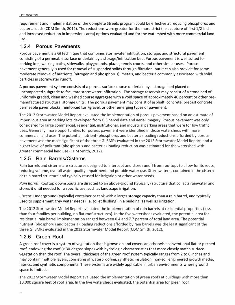
Figure 2‐1. Aerial Photo of Central Square
SECTION 2
Green Infrastructure Demonstration Projects 2.1 Central Square, East Boston 2.1.1 Description of Site & Owners Central Square is owned by the City of Boston Parks and Recreation Department. It is an urban park located in the Central Square District, a thriving commercial Main Streets District in the heart of East Boston (Figure 2‐1). The Park is surrounded by several streets that are owned by the Boston Public Works Department including Border Street to the west, Saratoga Street to the north, and Meridian Street to the east. The park can be characterized by pedestrian pathways that link several highly used intersections with an established existing tree canopy. Several small parking areas and two bus stops are located on the edges of the park. Runoff from the site generally drains to Boston Harbor, but a portion also drains to the combined sewer maintained by the BWSC.
Central Square was identified as a priority project in the 2008 East Boston Transportation Action Plan. The renovation of Central Square was initiated to improve the space with the following design objectives identified by the community: safe pedestrian crossings; parking and loading to support small businesses; more open space and better use of the park; a reduction in pavement; organization and improvement of traffic circulation; and consolidation of bus stops. In January, 2012, BWSC identified the project as a potential demonstration area for GI and began coordination with the Boston Transportation Department (BTD), Boston Public Works Department (BPW), and Boston Parks and Recreation Department (Parks) to include GI elements in the park improvements project.
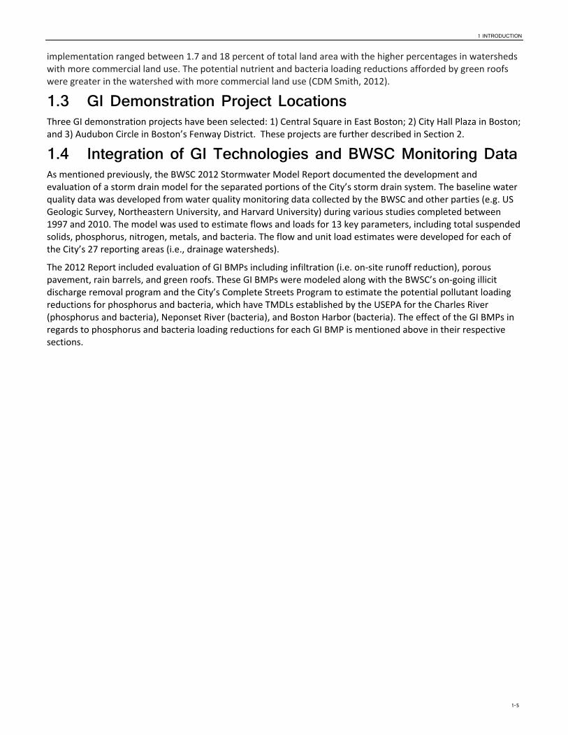
2.1.2 GI Goals, Plan & Status The preliminary GI design for Central Square consists of 11 stormwater management systems utilizing combinations of the following technologies: porous asphalt, precast porous concrete, gravel trenches and tree trenches with sand‐based structural soils (Figure 2‐2). Five of the proposed stormwater systems are interconnected, while the remaining six are independent. Each system includes one or more of the following structures/components: catch basin(s), cleanout(s), an overflow control structure, and an access well for passive observation and sampling. A flow meter will be strategically located such that any discharges from six of the systems can be measured. These metered systems collectively account for approximately 79 percent of the total runoff managed at the site. The GI design elements proposed for Central Square will target reduction in suspended solids, nutrients (nitrogen and phosphorus), metals, and bacteria.
The overall goal of the GI design is to eliminate the volume of runoff associated with the 1‐inch storm event (approximately 0.26 acre‐feet) via infiltration and/or evapotranspiration by the proposed trees. Thus, the various stormwater systems have been sized with enough dead storage (40 percent voids for aggregate per industry standard and 20 percent voids for sand‐based structural soil) to temporarily hold 1 inch of runoff from the contributory drainage area (approximately 3.1 acres, excluding the interior of the park) until it can be infiltrated and/or evapotranspired by the trees. Another important goal of the project is to provide adequate surface drainage for the streets and paved surfaces adjacent to Central Square. To this end, a hydraulic model of the local GI system proposed for Central Square was developed to demonstrate that the proposed hydraulics allow for all
2 GREEN INFRASTRUCTURE DEMONSTRATION PROJECTS
2-2
storms up to and including the 10‐year, 24‐hour storm to pass through the system without surface flooding. Infiltration test results were not available for the site; however, boring logs suggest that a uniform infiltration rate of 1/2‐inch/hour is a reasonable, if not conservative, assumption for each GI system. Test pits have been requested of BTD’s civil engineer for inclusion in final contract documents.
Figure 2‐2. Site Plan of Central Square Showing Proposed GI Technologies and Flow Pathways
This project is currently in the final design phase and GI system design is being coordinated with the landscape and transportation elements. Final construction documents are expected to be completed early summer 2013 by BTD’s engineer and that construction should start late summer of 2013. The BWSC has identified $543,000 from their 2013‐2015 Capital Improvement Plan budget towards the construction and maintenance of the GI system.
2.1.3 Monitoring Plan One purpose of a monitoring plan is to assess the performance of the GI facilities to verify that the design intent is being met for control of runoff volume. Currently the Central Square design includes one drain manhole (DMH‐17 on Green Stormwater Infrastructure (GSI) Draft Contract Drawing; prepared by CH2M HILL; May 2013) that captures approximately 79 percent of the project drainage area; this drain manhole allows for a meter placement. The design does allow for additional meters to be placed within the irrigation control manholes (i.e., outlets from the other GI systems) should additional monitoring be desired in the future. The flow monitoring could be accomplished by the use of a continuous monitoring device incorporating a velocity sensor combined with a depth sensor. Monitoring and reporting could be conducted with support from a subcontracted flow monitoring consultant. Flow monitoring may be complemented by routine inspection of the various observation wells by BWSC staff to determine if the various stormwater trenches are draining down within a reasonable duration following a storm event. Data obtained will be summarized, evaluated, and presented in report form. It is anticipated that tabular reports would be generated and include the following items:
2 GREEN INFRASTRUCTURE DEMONSTRATION PROJECTS
2-3
A summary report of daily flow information for a selected time period including for each day, the minimum flow rate, peak flow rate, total daily flow, total rain, peak hourly rain, and peak 15‐minute rainfall, if applicable. The summary also includes the total flow volume, average daily flow, and total rainfall quantity, if applicable, for the selected time period.
Detailed flow reports of the flow rate data in 15‐minute time increments will also be prepared. The detailed report will include depth of flow, velocity of flow, incremental flow rate, cumulative flow rate and recorded rainfall. The report will also include the total daily flow volume and total daily rainfall quantity, if applicable.
In addition, flow hydrographs will be prepared for each flow monitoring location, which present a plot of the recorded flow rates for a selected time period. A bar graph of rainfall recorded during the selected time period will also plotted on the hydrograph.
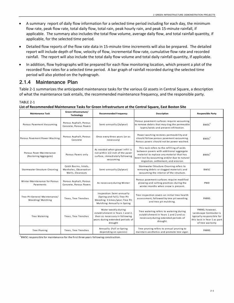
2.1.4 Maintenance Plan Table 2‐1 summarizes the anticipated maintenance tasks for the various GI assets in Central Square, a description of what the maintenance task entails, the recommended maintenance frequency, and the responsible party.
TABLE 2‐1 List of Recommended Maintenance Tasks for Green Infrastructure at the Central Square, East Boston Site
Maintenance TaskGreen Infrastructure/
TechnologyRecommended Frequency Description Responsible Party
Porous Pavement VacuumingPorous Asphalt, Porous
Concrete, Porous PaversSemi ‐annual ly (2x/year)
Porous pavement surfaces require vacuuming
to remove debris that may clog the permeable
l ayers/voids and prevent infi l tration.BWSC
1
Porous Pavement Power WashingPorous Asphalt, Porous
Concrete
Once every three years (or as
necessary)
Power washing restores permeabi l i ty and
should fol low porous pavement vacuuming.
Porous pavers should not be power washed.BWSC
1
Porous Paver Maintenance
(Restoring Aggregate)Porous Pavers only
As needed when gravel infi l l i s
not within 1/2 inch of the paver
surface, immediately fol lowing
vacuuming
This task refers to the refi l l ing of voids
between pavers with additional aggregate
materia l to replace any materia l that has
been lost by vacuuming and/or due to natura l
migration, settlement, and eros ion.
BWSC1
Stormwater Structure Cleaning
Catch Bas ins , Inlets ,
Manholes , Observation
Wells , Cleanouts
Semi ‐annual ly (2x/year)
Stormwater Structure Cleaning refers to
removing debris or clogged materia l s and
vacuuming the interior of the structure.
BWSC
Winter Maintenance for Porous
Pavements
Porous Asphalt, Porous
Concrete, Porous PaversAs necessary during Winter
Porous pavement surfaces requi re modi fied
plowing and sa l ting practices during the
winter months when snow i s present.
PWD
Tree Pit Genera l Maintenance/
Weeding/ MulchingTrees , Tree Trenches
Inspection: Semi ‐annual ly
(Spring and Fal l ); Tree Pit
Weeding: 3 times/year; Tree Pit
Mulching: Annual ly in Spring
Tree inspection covers an ini tia l tree health
assessment, fol lowed by tree pit weeding
and tree pi t mulching.
PARKS
Tree Watering Trees , Tree Trenches
Water weekly during
establ ishment in Years 1 and 2,
then as necessary in fol lowing
years during extended periods of
drought
Tree watering refers to watering during
establ ishment in Years 1 and 2 and as
necessary during extended periods of
drought.
PARKS; however,
Landscape Contractor i s
typica l l y respons ible for
this task in Year 1 as part
of tree warranty
Tree Pruning Trees , Tree TrenchesAnnual ly (Fa l l or Spring
depending on species)
Tree pruning refers to annual pruning to
mainta in aesthetics and promote tree vigor.PARKS
1BWSC responsible for maintenance for the first three years following construction.
2 GREEN INFRASTRUCTURE DEMONSTRATION PROJECTS
2-4
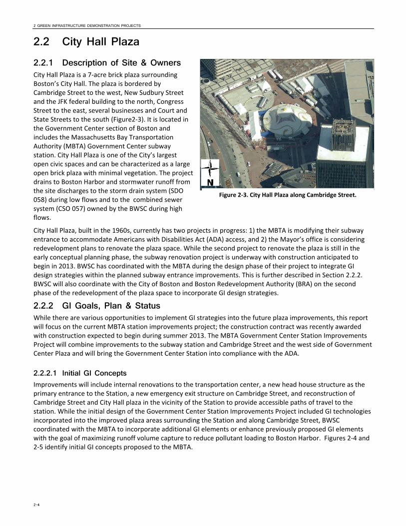
Figure 2‐3. City Hall Plaza along Cambridge Street.
2.2 City Hall Plaza 2.2.1 Description of Site & Owners City Hall Plaza is a 7‐acre brick plaza surrounding Boston’s City Hall. The plaza is bordered by Cambridge Street to the west, New Sudbury Street and the JFK federal building to the north, Congress Street to the east, several businesses and Court and State Streets to the south (Figure2‐3). It is located in the Government Center section of Boston and includes the Massachusetts Bay Transportation Authority (MBTA) Government Center subway station. City Hall Plaza is one of the City’s largest open civic spaces and can be characterized as a large open brick plaza with minimal vegetation. The project drains to Boston Harbor and stormwater runoff from the site discharges to the storm drain system (SDO 058) during low flows and to the combined sewer system (CSO 057) owned by the BWSC during high flows.
City Hall Plaza, built in the 1960s, currently has two projects in progress: 1) the MBTA is modifying their subway entrance to accommodate Americans with Disabilities Act (ADA) access, and 2) the Mayor’s office is considering redevelopment plans to renovate the plaza space. While the second project to renovate the plaza is still in the early conceptual planning phase, the subway renovation project is underway with construction anticipated to begin in 2013. BWSC has coordinated with the MBTA during the design phase of their project to integrate GI design strategies within the planned subway entrance improvements. This is further described in Section 2.2.2. BWSC will also coordinate with the City of Boston and Boston Redevelopment Authority (BRA) on the second phase of the redevelopment of the plaza space to incorporate GI design strategies.
2.2.2 GI Goals, Plan & Status While there are various opportunities to implement GI strategies into the future plaza improvements, this report will focus on the current MBTA station improvements project; the construction contract was recently awarded with construction expected to begin during summer 2013. The MBTA Government Center Station Improvements Project will combine improvements to the subway station and Cambridge Street and the west side of Government Center Plaza and will bring the Government Center Station into compliance with the ADA.
2.2.2.1 Initial GI Concepts Improvements will include internal renovations to the transportation center, a new head house structure as the primary entrance to the Station, a new emergency exit structure on Cambridge Street, and reconstruction of Cambridge Street and City Hall plaza in the vicinity of the Station to provide accessible paths of travel to the station. While the initial design of the Government Center Station Improvements Project included GI technologies incorporated into the improved plaza areas surrounding the Station and along Cambridge Street, BWSC coordinated with the MBTA to incorporate additional GI elements or enhance previously proposed GI elements with the goal of maximizing runoff volume capture to reduce pollutant loading to Boston Harbor. Figures 2‐4 and 2‐5 identify initial GI concepts proposed to the MBTA.
2 GREEN INFRASTRUCTURE DEMONSTRATION PROJECTS
2-5
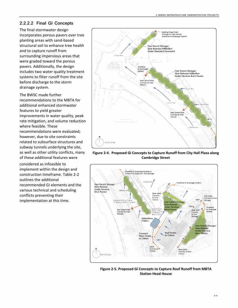
Figure 2‐5. Proposed GI Concepts to Capture Roof Runoff from MBTA Station Head House
Figure 2‐4. Proposed GI Concepts to Capture Runoff from City Hall Plaza along Cambridge Street
2.2.2.2 Final GI Concepts The final stormwater design incorporates porous pavers over tree planting areas with sand‐based structural soil to enhance tree health and to capture runoff from surrounding impervious areas that were graded toward the porous pavers. Additionally, the design includes two water quality treatment systems to filter runoff from the site before discharge to the storm drainage system.
The BWSC made further recommendations to the MBTA for additional enhanced stormwater features to yield greater improvements in water quality, peak rate mitigation, and volume reduction where feasible. These recommendations were evaluated; however, due to site constraints related to subsurface structures and subway tunnels underlying the site, as well as other utility conflicts, many of these additional features were
considered as infeasible to implement within the design and construction timeframe. Table 2‐2 outlines the additional recommended GI elements and the various technical and scheduling conflicts preventing their implementation at this time.
2 GREEN INFRASTRUCTURE DEMONSTRATION PROJECTS
2-6
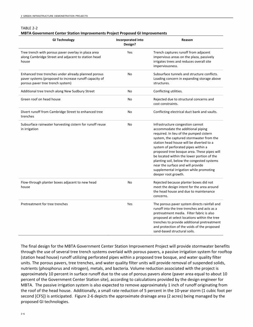
TABLE 2‐2 MBTA Government Center Station Improvements Project Proposed GI Improvements
GI Technology Incorporated into Design?
Reason
Tree trench with porous paver overlay in plaza area along Cambridge Street and adjacent to station head house
Yes Trench captures runoff from adjacent impervious areas on the plaza, passively irrigates trees and reduces overall site imperviousness.
Enhanced tree trenches under already planned porous paver systems (proposed to increase runoff capacity of porous paver tree trench system)
No Subsurface tunnels and structure conflicts. Loading concern in expanding storage above structures.
Additional tree trench along New Sudbury Street No Conflicting utilities.
Green roof on head house No Rejected due to structural concerns and cost constraints.
Divert runoff from Cambridge Street to enhanced tree trenches
No Conflicting electrical duct bank and vaults.
Subsurface rainwater harvesting cistern for runoff reuse in irrigation
No Infrastructure congestion cannot accommodate the additional piping required. In lieu of the pumped cistern system, the captured stormwater from the station head house will be diverted to a system of perforated pipes within a proposed tree bosque area. These pipes will be located within the lower portion of the planting soil, below the congested systems near the surface and will provide supplemental irrigation while promoting deeper root growth.
Flow‐through planter boxes adjacent to new head house
No Rejected because planter boxes did not meet the design intent for the area around the head house and due to maintenance concerns.
Pretreatment for tree trenches Yes The porous paver system directs rainfall and runoff into the tree trenches and acts as a pretreatment media. Filter fabric is also proposed at select locations within the tree trenches to provide additional pretreatment and protection of the voids of the proposed sand‐based structural soils.
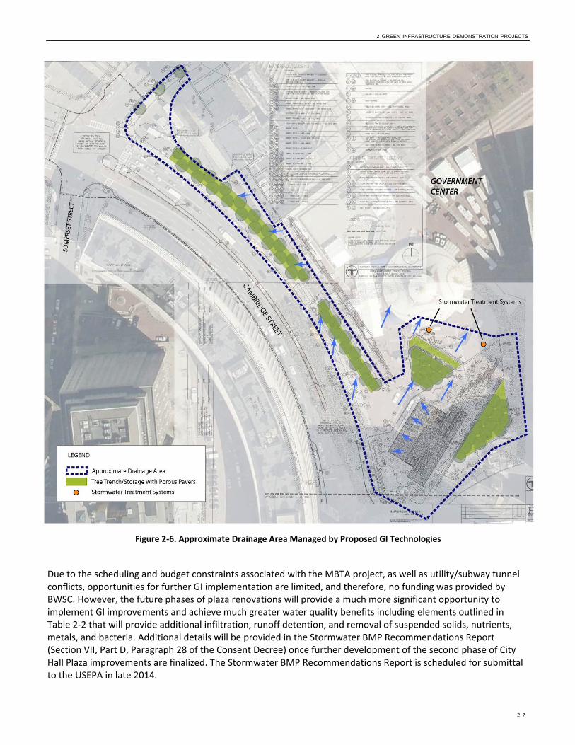
The final design for the MBTA Government Center Station Improvement Project will provide stormwater benefits through the use of several tree trench systems overlaid with porous pavers, a passive irrigation system for rooftop (station head house) runoff utilizing perforated pipes within a proposed tree bosque, and water quality filter units. The porous pavers, tree trenches, and water quality filter units will provide removal of suspended solids, nutrients (phosphorus and nitrogen), metals, and bacteria. Volume reduction associated with the project is approximately 10 percent in surface runoff due to the use of porous pavers alone (paver area equal to about 10 percent of the Government Center Station site), according to calculations provided by the design engineer for MBTA. The passive irrigation system is also expected to remove approximately 1 inch of runoff originating from the roof of the head house. Additionally, a small rate reduction of 5 percent in the 10‐year storm (1 cubic foot per second [CFS]) is anticipated. Figure 2‐6 depicts the approximate drainage area (2 acres) being managed by the proposed GI technologies.
2 GREEN INFRASTRUCTURE DEMONSTRATION PROJECTS
2-7
Figure 2‐6. Approximate Drainage Area Managed by Proposed GI Technologies
Due to the scheduling and budget constraints associated with the MBTA project, as well as utility/subway tunnel conflicts, opportunities for further GI implementation are limited, and therefore, no funding was provided by BWSC. However, the future phases of plaza renovations will provide a much more significant opportunity to implement GI improvements and achieve much greater water quality benefits including elements outlined in Table 2‐2 that will provide additional infiltration, runoff detention, and removal of suspended solids, nutrients, metals, and bacteria. Additional details will be provided in the Stormwater BMP Recommendations Report (Section VII, Part D, Paragraph 28 of the Consent Decree) once further development of the second phase of City Hall Plaza improvements are finalized. The Stormwater BMP Recommendations Report is scheduled for submittal to the USEPA in late 2014.
2 GREEN INFRASTRUCTURE DEMONSTRATION PROJECTS
2-8
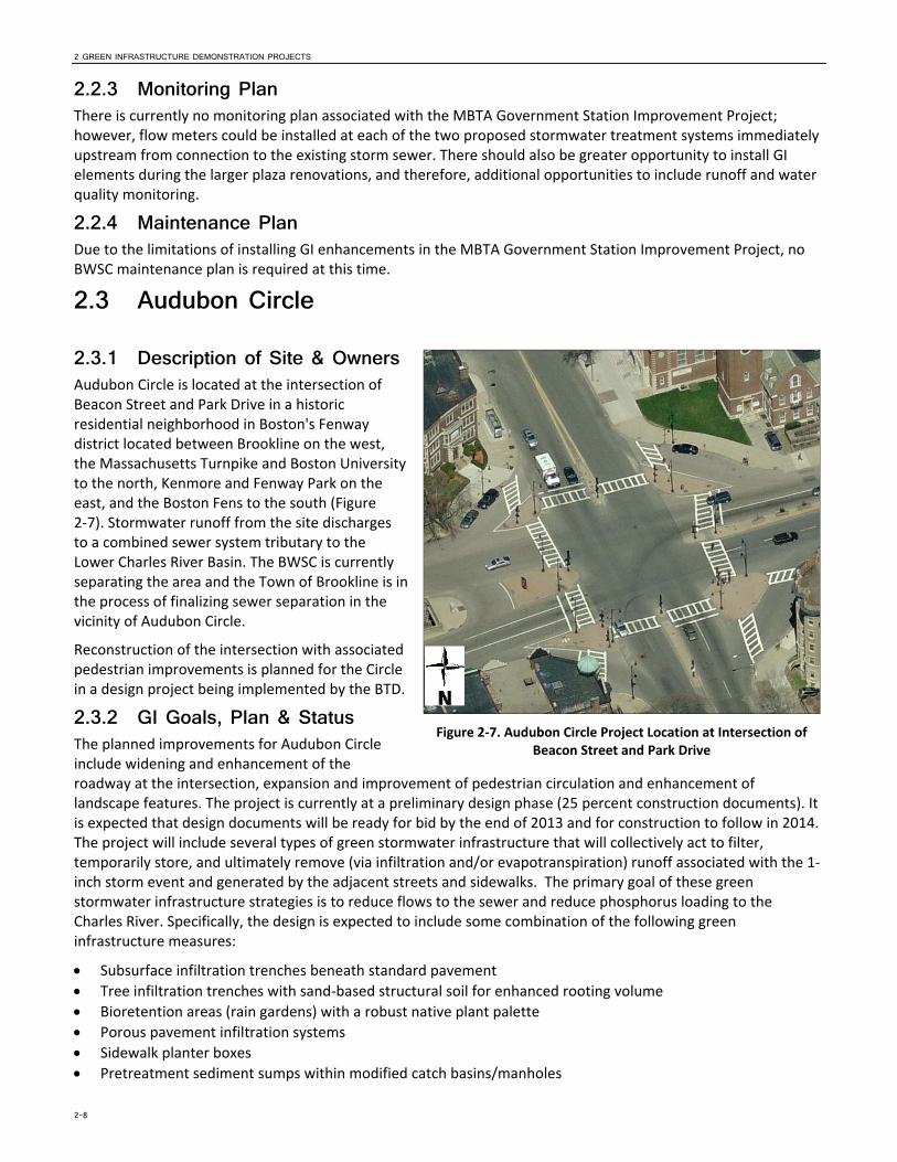
Figure 2‐7. Audubon Circle Project Location at Intersection of Beacon Street and Park Drive
2.2.3 Monitoring Plan There is currently no monitoring plan associated with the MBTA Government Station Improvement Project; however, flow meters could be installed at each of the two proposed stormwater treatment systems immediately upstream from connection to the existing storm sewer. There should also be greater opportunity to install GI elements during the larger plaza renovations, and therefore, additional opportunities to include runoff and water quality monitoring.
2.2.4 Maintenance Plan Due to the limitations of installing GI enhancements in the MBTA Government Station Improvement Project, no BWSC maintenance plan is required at this time.
2.3 Audubon Circle
2.3.1 Description of Site & Owners Audubon Circle is located at the intersection of Beacon Street and Park Drive in a historic residential neighborhood in Boston's Fenway district located between Brookline on the west, the Massachusetts Turnpike and Boston University to the north, Kenmore and Fenway Park on the east, and the Boston Fens to the south (Figure 2‐7). Stormwater runoff from the site discharges to a combined sewer system tributary to the Lower Charles River Basin. The BWSC is currently separating the area and the Town of Brookline is in the process of finalizing sewer separation in the vicinity of Audubon Circle.
Reconstruction of the intersection with associated pedestrian improvements is planned for the Circle in a design project being implemented by the BTD.
2.3.2 GI Goals, Plan & Status The planned improvements for Audubon Circle include widening and enhancement of the roadway at the intersection, expansion and improvement of pedestrian circulation and enhancement of landscape features. The project is currently at a preliminary design phase (25 percent construction documents). It is expected that design documents will be ready for bid by the end of 2013 and for construction to follow in 2014. The project will include several types of green stormwater infrastructure that will collectively act to filter, temporarily store, and ultimately remove (via infiltration and/or evapotranspiration) runoff associated with the 1‐inch storm event and generated by the adjacent streets and sidewalks. The primary goal of these green stormwater infrastructure strategies is to reduce flows to the sewer and reduce phosphorus loading to the Charles River. Specifically, the design is expected to include some combination of the following green infrastructure measures:
Subsurface infiltration trenches beneath standard pavement
Tree infiltration trenches with sand‐based structural soil for enhanced rooting volume
Bioretention areas (rain gardens) with a robust native plant palette
Porous pavement infiltration systems
Sidewalk planter boxes
Pretreatment sediment sumps within modified catch basins/manholes
2 GREEN INFRASTRUCTURE DEMONSTRATION PROJECTS
2-9
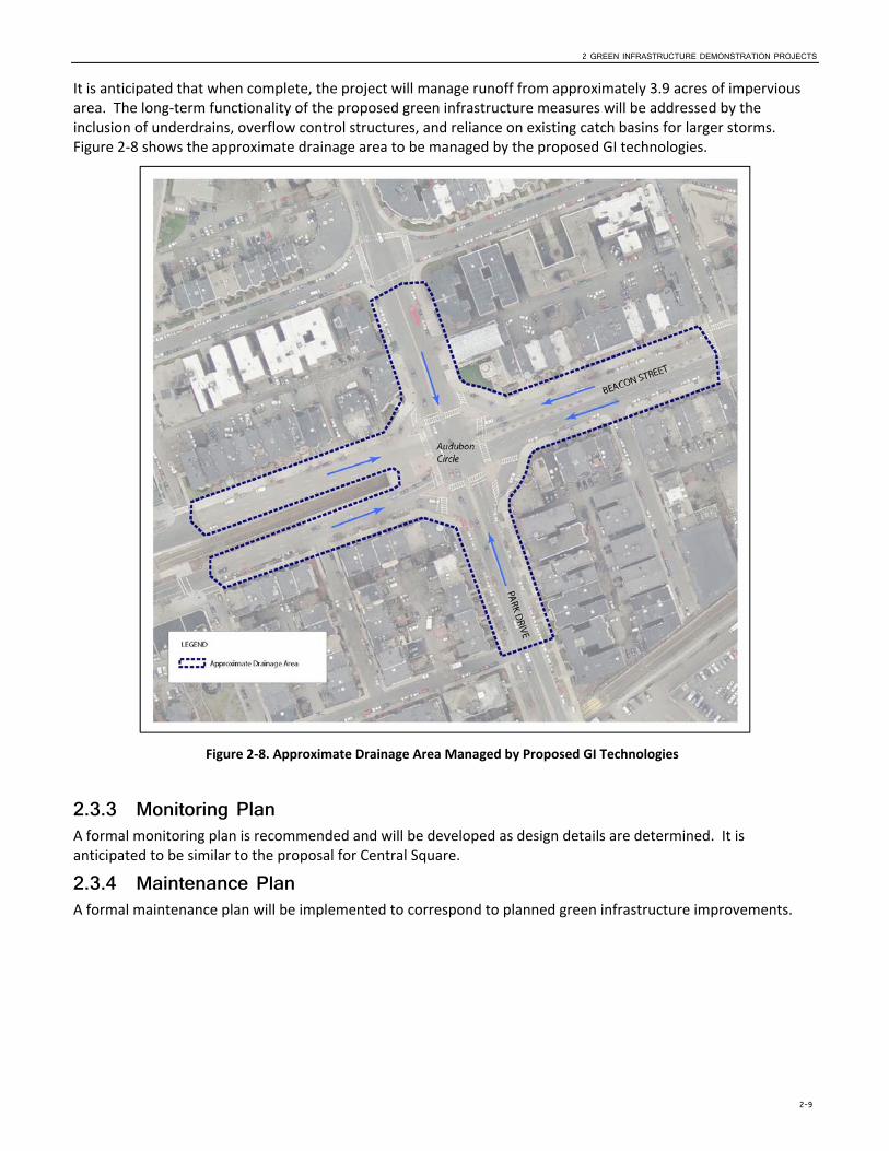
Figure 2‐8. Approximate Drainage Area Managed by Proposed GI Technologies
It is anticipated that when complete, the project will manage runoff from approximately 3.9 acres of impervious area. The long‐term functionality of the proposed green infrastructure measures will be addressed by the inclusion of underdrains, overflow control structures, and reliance on existing catch basins for larger storms. Figure 2‐8 shows the approximate drainage area to be managed by the proposed GI technologies.
2.3.3 Monitoring Plan A formal monitoring plan is recommended and will be developed as design details are determined. It is anticipated to be similar to the proposal for Central Square.
2.3.4 Maintenance Plan A formal maintenance plan will be implemented to correspond to planned green infrastructure improvements.

3-1
SECTION 3
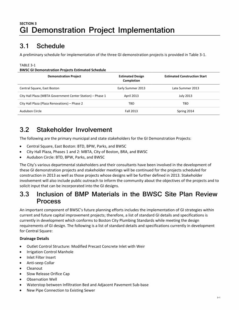
GI Demonstration Project Implementation 3.1 Schedule A preliminary schedule for implementation of the three GI demonstration projects is provided in Table 3‐1.
TABLE 3‐1 BWSC GI Demonstration Projects Estimated Schedule
Demonstration Project Estimated Design Completion
Estimated Construction Start
Central Square, East Boston Early Summer 2013 Late Summer 2013
City Hall Plaza (MBTA Government Center Station) – Phase 1 April 2013 July 2013
City Hall Plaza (Plaza Renovations) – Phase 2 TBD TBD
Audubon Circle Fall 2013 Spring 2014
3.2 Stakeholder Involvement The following are the primary municipal and state stakeholders for the GI Demonstration Projects:
Central Square, East Boston: BTD, BPW, Parks, and BWSC
City Hall Plaza, Phases 1 and 2: MBTA, City of Boston, BRA, and BWSC
Audubon Circle: BTD, BPW, Parks, and BWSC
The City’s various departmental stakeholders and their consultants have been involved in the development of these GI demonstration projects and stakeholder meetings will be continued for the projects scheduled for construction in 2013 as well as those projects whose designs will be further defined in 2013. Stakeholder involvement will also include public outreach to inform the community about the objectives of the projects and to solicit input that can be incorporated into the GI designs.
3.3 Inclusion of BMP Materials in the BWSC Site Plan Review Process
An important component of BWSC’s future planning efforts includes the implementation of GI strategies within current and future capital improvement projects; therefore, a list of standard GI details and specifications is currently in development which conforms to Boston City Plumbing Standards while meeting the design requirements of GI design. The following is a list of standard details and specifications currently in development for Central Square:
Drainage Details
Outlet Control Structure: Modified Precast Concrete Inlet with Weir
Irrigation Control Manhole
Inlet Filter Insert
Anti‐seep Collar
Cleanout
Slow Release Orifice Cap
Observation Well
Waterstop between Infiltration Bed and Adjacent Pavement Sub‐base
New Pipe Connection to Existing Sewer
3 GI DEMONSTRATION PROJECT IMPLEMENTATION
3-2
New Pipe Connection to Existing Manhole
Utility Protection: Concrete Encasement of Storm Pipe over Existing Water Line
Utility Protection: Utility Sleeve (Geomembrane and Split Pipe)
Infiltration Trench/Bed
Infiltration Trench/Bed Under Standard Pavement: General
Infiltration Trench/Bed Under Standard Pavement: Street
Infiltration Trench/Bed Under Standard Pavement: Sidewalk
Infiltration Trench/Bed Under Standard Pavement: Street/Sidewalk with Curb
Typical Tree Trench with Sand‐Based Structural Soil
Porous Pavement
Typical Porous Pavement Bed Section: Porous Asphalt
Typical Porous Pavement Bed Section: Porous Concrete
Typical Porous Pavement Bed Section: Pre‐cast Porous Concrete Paving Slabs
Typical Porous Pavement Bed Section: Porous Pavers
Others (not in Central Square design but may be applicable elsewhere)
Typical Bioretention Section
Typical Vegetated Curb Extension Section
Typical Stone/Granite Splashpad
Typical Curb Opening

4-1
SECTION 4
References CDM Smith. 2012. Boston Water and Sewer Commission 2012 Stormwater Model Report. December.
BWSC. 2013. Boston Water and Sewer Commission Stormwater Best Practices: Guidance Document. January.
Recommended