P.O. Box 1306, Newport Beach, California 92663 • Phone: 714-751-0488 • Fax: 714-957-1621 • E-Mail: [email protected]
www.newmartelecom.com1
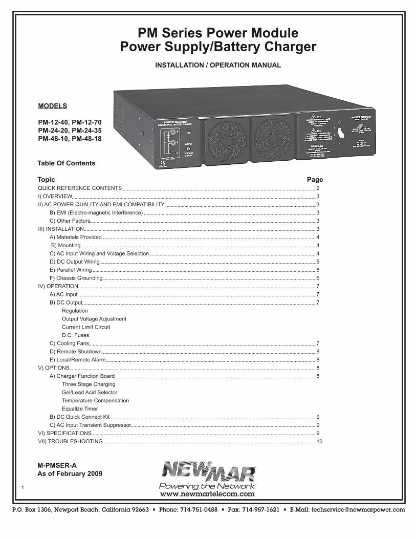
PM Series Power ModulePower Supply/Battery Charger
INSTALLATION / OPERATION MANUAL
MODELS
PM-12-40, PM-12-70PM-24-20, PM-24-35PM-48-10, PM-48-18
Table Of Contents
Topic PageQUICK REFERENCE CONTENTS 2
I) OVERVIEW 3
II) AC POWER QUALITY AND EMI COMPATIBILITY 3
B) EMI (Electro-magnetic Interference) 3
C) Other Factors 3
III) INSTALLATION 3
A) Materials Provided 4
B) Mounting 4
C) AC Input Wiring and Voltage Selection 4
D) DC Output Wiring 5
E) Parallel Wiring 6
F) Chassis Grounding 6
IV) OPERATION 7
A) AC Input 7
B) DC Output 7
Regulation
Output Voltage Adjustment
Current Limit Circuit
D.C. Fuses
C) Cooling Fans 7
D) Remote Shutdown 8
E) Local/Remote Alarm 8
V) OPTIONS 8
A) Charger Function Board 8
Three Stage Charging
Gel/Lead Acid Selector
Temperature Compensation
Equalize Timer
B) DC Quick Connect Kit 9
C) AC Input Transient Suppressor 9
VI) SPECIFICATIONS 9
VII) TROUBLESHOOTING 10
M-PMSER-AAs of February 2009
P.O. Box 1306, Newport Beach, California 92663 • Phone: 714-751-0488 • Fax: 714-957-1621 • E-Mail: [email protected]
www.newmartelecom.com2
P.O. Box 1306, Newport Beach, California 92663 • Phone: 714-751-0488 • Fax: 714-957-1621 • E-Mail: [email protected]
www.newmartelecom.com
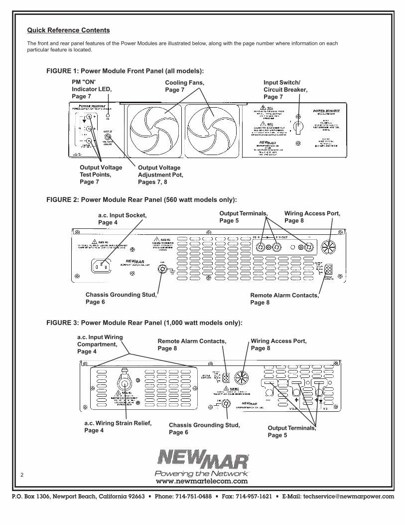
Quick Reference Contents
The front and rear panel features of the Power Modules are illustrated below, along with the page number where information on each particular feature is located.
FIGURE 2: Power Module Rear Panel (560 watt models only):
FIGURE 3: Power Module Rear Panel (1,000 watt models only):
FIGURE 1: Power Module Front Panel (all models):
Cooling Fans,Page 7
Output VoltageAdjustment Pot,Pages 7, 8
Output VoltageTest Points,Page 7
PM "ON'Indicator LED,Page 7
Input Switch/Circuit Breaker,Page 7
a.c. Input Socket,Page 4
Output Terminals,Page 5
Wiring Access Port,Page 8
Remote Alarm Contacts,Page 8
Chassis Grounding Stud,Page 6
a.c. Wiring Strain Relief,Page 4
Chassis Grounding Stud,Page 6
Remote Alarm Contacts,Page 8
Wiring Access Port,Page 8
Output Terminals,Page 5
a.c. Input WiringCompartment,Page 4
P.O. Box 1306, Newport Beach, California 92663 • Phone: 714-751-0488 • Fax: 714-957-1621 • E-Mail: [email protected]
www.newmartelecom.com
P.O. Box 1306, Newport Beach, California 92663 • Phone: 714-751-0488 • Fax: 714-957-1621 • E-Mail: [email protected]
www.newmartelecom.com3
I) Overview
The PM Series Power Module is a uniquely adaptable communication equipment power source which functions as either power supply or battery charger for 12, 24 or 48 volt d.c. systems positive, negative or floating ground. Power Modules may be employed singly or in combina tion, enabling the installer to scale the system output from 560 to 6,000 watts per rack. Units may be paral leled for N + 1 redundancy and alarm contacts allow local or remote mon itoring. An optional d.c. wiring quick connect kit allows easy replacement of modules while the system as a whole remains up and running (see section V-B).
Power Modules may be used separately as a power source, or they may be integrated with NEWMAR’s Power Function Manager (model PFM-400; rated to 400 amps maximum) to greatly expand the system capability with other functions such as digital output monitoring, multiple load distribution and low voltage disconnect. (Contact the factory for complete information regarding the PFM-400.) Note: If the Power Module is being installed as part of an integrated system with the PFM-400 refer to the manual which comes with that unit for all d.c. wiring instructions and functional descriptions.
II) AC Power Quality and EMI Compatibility
A) AC Power QualityReliability is of prime concern when designing an AC-DC power system for communication sites. Poor AC input power quality can seriously impede system reliability. In particular, transient disturbances on the power lines can severely weaken or cause failure of semi-conductors in power supplies and communication gear. It is important that you know the input power quality when installing the PM. Following is some basic information on the subject:
CausesTransients are characterized as a voltage pulse of high energy and very short duration impressed upon the AC wave form. These over voltage pulses can range from 1 to 100 times the normal AC voltage level and can last for a fraction of a cycle to a few cycles.
Transient disturbances can be placed into two categories:- Lightning generated- Equipment generated
A direct lightning hit on a utility power line will cause a high energy voltage transient to travel in both directions along the power line. This disturbance can affect equipment hundreds of miles from the strike point.
Equipment generated transient sources include utility fault conditions and load switching as well as on-site equipment such as pumps and air conditioning loads, motors, phase control equipment.
RecommendationsAll PM models are designed to meet IEEE 587/ANSI C62.41 requirementsfor transient withstand capability. The AC power source should conform to this specification to ensure reliable power supply operation.
If the power source quality is suspect or unknown, it is recommended that an AC power quality survey be conducted by a power quality consultant or power conditioning firm. Corrective measures may include lightning suppressors, line conditioners and filters.
An optional AC transient suppressor (see OPTIONS section) is recommended for installations in third world countries and sites that are subject to nearby lightning strikes or transients caused by nearby motor contactors, air conditioning compressors, etc.
B) EMI (Electro-Magnetic Interference) ConsiderationsThe PM Series Power Modules employ switch-mode technology to con-vert AC to DC. They are designed to produce minimal EMI levels when operating (compliant to International Standards EN55022 [conducted] and EN50082 [immunity]). Although the level of EMI produced may be acceptable for most radio applications, some installations may not even tolerate what little EMI isproduced.
Analog microwave and other extremely sensitive radio sites may require additional input/output filtering and careful installation. In some cases linear power supplies (also available from NEWMAR) should be considered, as they emit lower EMI (although they are more susceptible to “brown-outs” or voltage sags and high input voltage).
C) Other FactorsSome of the various factors which must be considered when discussing electrical interference include the following: - RF Signal strength - Ground loops - Power and signal cable routing proximity - Power supply and radio mounting locations - Antenna, signal, and power grounds
III) Installation
Two notes regarding nomenclature used in this manual
1) For the sake of brevity the PM Series Power Module is referred to simply as the PM (meaning all models, generically).
2) Where installation differences exist, reference is made to 560 watt or 1,000 watt models.
560 watt models refers to: PM-12-40PM-24-20PM-48-10
1,000 watt models refers to: PM-12-70PM-24-35PM-48-18
Note: This section covers only mounting, input and output wiring. Two installation options, Remote Shutdown wiring and Local/Remote Alarm wiring, are covered in those sections in the OPERATION portion of this manual.
P.O. Box 1306, Newport Beach, California 92663 • Phone: 714-751-0488 • Fax: 714-957-1621 • E-Mail: [email protected]
www.newmartelecom.com4
P.O. Box 1306, Newport Beach, California 92663 • Phone: 714-751-0488 • Fax: 714-957-1621 • E-Mail: [email protected]
www.newmartelecom.com
A) Materials Provided
Prior to installation, check to ensure that each of the following items have been included with the packaging. For any missing items please contact the factory or warehouse.
(2) ea. mounting brackets for 19” rack mounting (# 13917-0)(2) ea. mounting brackets for 23” rack mounting (# 13918-0)(6) ea. 6-32 X 3/8” pan head phillips screws(1) ea. Molex “pigtail” connector(1) ea. IEC 115V NEMA 5-15P AC input power cord (560 watt models only)(1) ea. 115V NEMA 5-20P AC input power cord (1000 watt models only)(1) ea. input connector/adaptor for 115V installations (1,000 watt models only); Note: 230 connector/adaptor has been factory installed along with 230V power cord.(1) ea. Installation/Operation manual(1) ea. Customer Satisfaction/Warranty card(1) ea. Output terminal cover (560 watt models only)
B) Mounting
The PM is provided with two pairs of mounting ears: one for 19” rack mounting (# 13917-0) and one for 23” rack mounting (# 13918-0). Six # 6-32 x 3/8” pan head Phillips screws are provided for attaching the ears to the PM chassis. Select the appropriate set of ears and fasten to the PM sides.
Note there are three sets of a triangular pattern of 6-32 tapped holes on each side of the PM. When rack mounting (two posts) the PM it is recommended that the ‘center mount’ holes (6” set back from the PM’s front panel) be used. The set of holes nearest the front panel and the set nearest the rear panel are normally used when installing the optional Universal Mounting Bracket (UMB).
For four post mounting, please contact the factory for a second set of ears (specify 19” or 23” and the model no.), mount one pair of ears to the front holes and the second pair of ears to the center or rear most tapped holes. Adjust your cabinet rail front to back distance so it matches the mounting holes on the PM.
Note: Due to the weight of the Power Module, we do not recommend flush mounting the PM with the mounting ears attached to the forward most mounting holes unless rear support is provided.
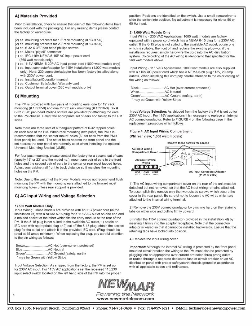
C) AC Input Wiring and Voltage Selection
1) 560 Watt Models OnlyInput Wiring: These models are provided with an IEC power cord (in the installation kit) with a NEMA 5-15 plug for a 115V AC outlet on one end and a molded socket at the other which fits the entry module at the rear of the PM. If the 5-15 plug is not suited to the available AC outlet, 1) obtain an IEC cord with appropriate plug or 2) cut off the 5-15 plug, obtain the correct plug for the outlet and attach it to the provided IEC cord. (Plug should be rated at 15 amps minimum). When replacing the plug, pay careful attention to the pin wiring as follows:
Brown.........................AC Hot (over-current protected) Blue............................AC Neutral Green*........................AC Ground (safety, earth) * may be Green with Yellow Stripe
Input Voltage Selection: As shipped from the factory, the PM is set up for 230V AC input. For 115V AC applications set the recessed 115/230 input select switch located on the left hand side of the PM into the proper
position. Positions are identified on the switch. Use a small screwdriver to slide the switch into position. No adjustment is necessary for either 50 or 60 Hz input.
2) 1,000 Watt Models OnlyInput Wiring - 230 VAC Applications: 1000 watt models are factory equipped with a power cord which has a NEMA 6-15 plug for a 230V AC outlet. If the 6-15 plug is not suited to the available AC outlet, obtain one which is suitable, then cut off and replace the existing plug—or, if the installation requires, simply hard-wire the cord into the AC distribution system. Color-coding of the AC wiring is identical to that specified for the 560 watt models above.
Input Wiring - 115 VAC Applications: 1000 watt models are also supplied with a 115V AC power cord which has a NEMA 5-20 plug 115V, 20 amp outlets. When installing this cord pay careful attention to the color coding of the wiring as follows:
Black............................AC Hot (over-current protected) White............................AC Neutral Green*..........................AC Ground (safety, earth) * may be Green with Yellow Stripe
Input Voltage Selection: As shipped from the factory the PM is set up for 230V AC input . For 115V applications it is necessary to replace an internal AC connector/adaptor. Refer to FIGURE 4 on the following page in the replacement procedure which follows:
Figure 4: AC Input Wiring Compartment
(PM rear view; 1,000 watt models)
1) The AC input wiring compartment cover on the rear of the unit must be detached but not removed, so that the AC input wiring remains attached. To accomplish this remove only the two outside screws which secure the cover to the rear panel. Be careful not to loosen the AC wires which are attached to the internal wiring terminal.
2) Remove the 230V connector/adaptor by pinching hard on the retaining tabs on either side and pulling firmly upward.
3) Install the 115V connector/adaptor (provided in the installation kit) by inserting it firmly into the adaptor receptacle. Note that the connector/adaptor is keyed so that it cannot be installed backwards. Ensure that the retaining tabs have locked into position.
4) Replace the input wiring cover.
Important: Although the internal AC wiring is protected by the front panel mounted circuit breaker, the wiring to the PM must also be protected by plugging into an appropriate over-current protected three prong outlet or routed through a separate dedicated fuse or circuit breaker on an AC distribution panel with proper safety/earth chassis ground in accordance with all applicable codes and ordinances.
AC Input Wiring Compartment Cover
Remove these screws for access
AC Input Connector/Adaptor (115V or 230V)
AC Input Terminal Wiring
HOT GND NEUT (LEFT) (CENTER) (RIGHT)
P.O. Box 1306, Newport Beach, California 92663 • Phone: 714-751-0488 • Fax: 714-957-1621 • E-Mail: [email protected]
www.newmartelecom.com
P.O. Box 1306, Newport Beach, California 92663 • Phone: 714-751-0488 • Fax: 714-957-1621 • E-Mail: [email protected]
www.newmartelecom.com5
Distribution Panel AC Fuse/Circuit Breaker Values560 watt 15 amp1,000 watt 20 amp
CAUTION (560 watt unit/230 V a.c applications only): If AC input is derived from a source consisting of two HOT leads (phase-to-phase 230V AC input voltage), an external fuse or circuit breaker (double pole) must be used to protect the unfused (formerly NEUTRAL, now HOT) lead.
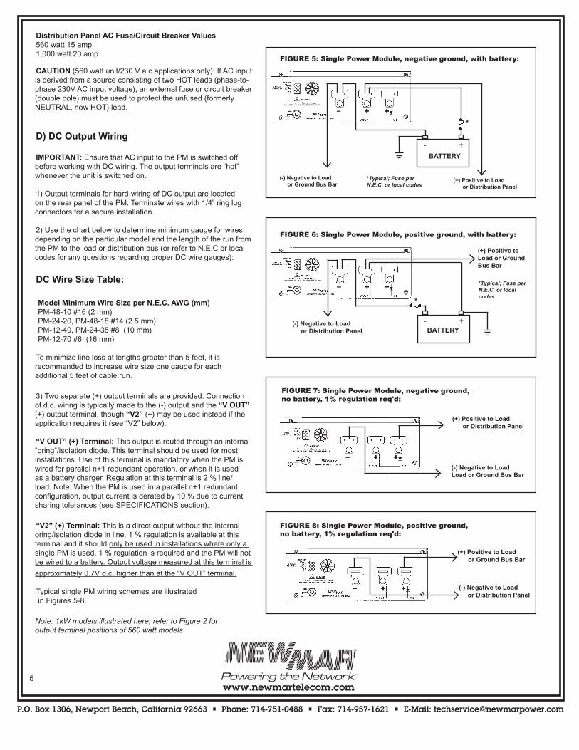
D) DC Output Wiring
IMPORTANT: Ensure that AC input to the PM is switched off before working with DC wiring. The output terminals are “hot” whenever the unit is switched on.
1) Output terminals for hard-wiring of DC output are located on the rear panel of the PM. Terminate wires with 1/4” ring lug connectors for a secure installation.
2) Use the chart below to determine minimum gauge for wires depend ing on the particular model and the length of the run from the PM to the load or distribution bus (or refer to N.E.C or local codes for any questions regarding proper DC wire gauges):
DC Wire Size Table:
Model Minimum Wire Size per N.E.C. AWG (mm) PM-48-10 #16 (2 mm) PM-24-20, PM-48-18 #14 (2.5 mm) PM-12-40, PM-24-35 #8 (10 mm) PM-12-70 #6 (16 mm)
To minimize line loss at lengths greater than 5 feet, it is recommended to increase wire size one gauge for each additional 5 feet of cable run.
3) Two separate (+) output terminals are provided. Connection of d.c. wiring is typically made to the (-) output and the “V OUT” (+) output ter minal, though “V2” (+) may be used instead if the application requires it (see “V2” below).
“V OUT” (+) Terminal: This output is routed through an internal “or ing”/isolation diode. This terminal should be used for most installations. Use of this terminal is mandatory when the PM is wired for parallel n+1 redundant operation, or when it is used as a battery charger. Regula tion at this terminal is 2 % line/load. Note: When the PM is used in a parallel n+1 redundant configuration, output current is derated by 10 % due to current sharing tolerances (see SPECIFICATIONS section).
“V2” (+) Terminal: This is a direct output without the internal oring/isolation diode in line. 1 % regulation is available at this terminal and it should only be used in installations where only a single PM is used, 1 % regulation is required and the PM will not be wired to a battery. Output voltage measured at this terminal is
approximately 0.7V d.c. higher than at the “V OUT” terminal.
Typical single PM wiring schemes are illustrated in Figures 5-8.
Note: 1kW models illustrated here; refer to Figure 2 foroutput terminal positions of 560 watt models
+
(+) Positive to Load or Distribution Panel
(-) Negative to Load or Ground Bus Bar
-
*
*Typical; Fuse perN.E.C. or local codes
FIGURE 5: Single Power Module, negative ground, with battery:
BATTERY
+-
*
(+) Positive to Load or Ground Bus Bar
(-) Negative to Load or Distribution Panel
*Typical; Fuse perN.E.C. or local codes
FIGURE 6: Single Power Module, positive ground, with battery:
BATTERY
FIGURE 8: Single Power Module, positive ground, no battery, 1% regulation req'd:
(+) Positive to Load or Ground Bus Bar
(-) Negative to Load or Distribution Panel
FIGURE 7: Single Power Module, negative ground, no battery, 1% regulation req'd:
(+) Positive to Load or Distribution Panel
(-) Negative to LoadLoad or Ground Bus Bar
P.O. Box 1306, Newport Beach, California 92663 • Phone: 714-751-0488 • Fax: 714-957-1621 • E-Mail: [email protected]
www.newmartelecom.com6
P.O. Box 1306, Newport Beach, California 92663 • Phone: 714-751-0488 • Fax: 714-957-1621 • E-Mail: [email protected]
www.newmartelecom.com
E) Parallel Wiring
The internal oring/isolation diode of the PM allows parallel n+1 redundant wiring with no modification or other external isolation de vices required. Figures 9-10 on the following page illustrate some typical parallel wiring schemes.
IMPORTANT: When wiring two or more units in parallel d.c. wires for all units should be identical in gauge and length and the output voltage of each module should be adjusted (as outlined below) in order to facilitate droop
load sharing.
Parallel Load Sharing Adjustment Procedures
Method 1:1) Shut off all but one of the Power Modules and apply a load equivalent to 1/2 of the rating for that unit (e.g., for model PM-12-70 apply a 35 amp load).
2) Connect a digital voltmeter to the test points on the front of the power module at the “V OUT” and (+) and (-) positions.
3) Verify that the output voltage is at the correct factory setting (see Specifications section) or at the desired system voltage. If adjustment is neces sary, use a small flat tip screwdriver to turn the “OUTPUT VOLTAGE ADJUST” potentiometer on the front panel until the voltmeter reads the desired system output voltage.
4) Shut off the PM, turn on the next unit in the system, and repeat steps 2 through 4 until all PM’s in the system have the identical “V OUT” output voltage.
Method 2:1) With all Power Modules powered up, apply the typical operational d.c. system load.
2) Using a clamp-on ammeter, measure the output current of each PM in the system. If there is an out-put current differential of greater than 5 % between any two PM’s, attach the ammeter to the PM with the highest output current and turn the “OUTPUT VOLTAGE ADJUST” potentiometer on that unit slowly counterclockwise, until the output current of that unit reduces slightly.
3) Repeat step 2 until there is less than 5 % current output differential between all PM’s in the system.
F) Chassis Grounding
If grounding of the PM chassis is required for the installation, use the provided 1/4” grounding stud on the rear panel for this purpose (see Figure 2 or 3).
PM # 3
PM # 2
PM # 1
(+) Positive to Distribution Panel or Battery (fuse at battery per N.E.C. or local codes)
(-) Negative to Loads or BatteryGround Bus Bar
FIGURE 9: Parallel (two to six Power Modules) and N+1 redundancy, negative ground
PM # 3
PM # 2
PM # 1
(-) Negative to Distribution Panel or Battery (fuse at battery per N.E.C. or local codes)
Ground Bus Bar(+) Positive to Loads or Battery
FIGURE 10: Parallel (two to six Power Modules) and N+1 redundancy, positive ground
Note: 1kW models illustrated here; refer to Figure 2 for output terminal positions of 560 watt models
P.O. Box 1306, Newport Beach, California 92663 • Phone: 714-751-0488 • Fax: 714-957-1621 • E-Mail: [email protected]
www.newmartelecom.com
P.O. Box 1306, Newport Beach, California 92663 • Phone: 714-751-0488 • Fax: 714-957-1621 • E-Mail: [email protected]
www.newmartelecom.com7
IV) Operation
A) AC Input
The PM will operate on either 115 or 230 VAC (+15% to -25%) input at 50-60 Hz. Input voltage selection is explained in the INSTALLATION section. No adjustment is required for 50 or 60 Hz. operation.
AC input is protected against over-current and internal short circuit condi-tions by the circuit breaker/input power switch on the front panel. When this switch is in the on position and DC is available at the output terminal, the “ON” indicator L.E.D. on the left side of the front panel will illuminate.
B) DC Output
The PM produces 12, 24 or 48 VDC nominal output, depending on model. The ground reference may be positive, negative or floating.
Regulation: Regulation at the “V OUT” output terminal is within ± 2 % of rated voltage, under all line and load conditions. Regulation at the “V2” terminal is ± 1 %. Ripple is within ± 1 % of rated voltage with or without batteries on-line.
Output Voltage Adjust: Factory-set voltages (as measured at the V OUT terminal) and approximate adjustment ranges are specified below. Adjust-ment is made at the “OUTPUT VOLTAGE ADJUST” pot on the left side of the front panel using a small flat tip screwdriver (see Figure 1). Output voltage test points for both the “V OUT” and “V2” outputs are provided beside the voltage adjust pot for ease of monitoring while making this adjustment. Use of a digital multimeter is recommended when making this adjustment. If the PM has had the charger function board installed, output
voltage adjustments are automatic and this adjustment pot is disabled.
Output Voltage Table
Factory Set “V OUT” “V OUT”
Model Output Voltage Adjustment RangePM-12-40, PM-12-70 13.6V DC 12.2 - 15V DCPM-24-20, PM-24-35 27.2V DC 24.4 - 30V d.cPM-48-18, PM-48-10 54.4V DC 48.8 - 60V DC
Current Limit Circuit: The PM is rated for continuous duty at the current level indicated by model number, e.g., PM-12-40 is rated at 40 amps con-tinuous duty. To prevent overload when recharging severely discharged batteries, current is limited at approximately 105 % of the continuous duty
rating by a current fold-back circuit.
DC Fuses: d.c output wiring is protected by internal DC output fuse(s). The current limiting circuit of the PM should prevent these fuses from blowing under normal operating conditions. If the d.c fuse(s) blow, this may indicate a reverse polarity hook-up or an internal short.
Always disconnect AC to the PM before checking fuses. To replace the DC fuse, the cover must be removed. The DC fuse is either an HBO type or an ATC blade type (depending on model) mounted on the main PCB. Be sure to replace with the same type and value as indicated on the fuse.
If the battery is connected to the PM output with backwards polarity, the fuse should blow to protect DC wiring. However damage to internal components may also have occurred. If the replacement fuse blows, return the PM to the factory for a thorough inspection.
C) Cooling Fans
To maximize the life of the internal components and to allow continu ous operation at full rating, the PM employs automatic cooling fans. These fans operate at full speed whenever AC is applied and the unit is producing DC output.
Preventative Maintenance: The fan is a maintenance-free ball-bearing type and does not require lubrication. It is equipped with a filter to keep debris from being sucked into the unit. It is recommended that this filter be removed and rinsed with water occasionally to ensure adequate air flow, particularly if the PM is installed in a dusty or particle-filled environ ment. Simply pry off the filter retainer with a flat tip screwdriver to clean or replace
the filter.
If the fan fails to operate when the PM is turned on and a load is applied, it may need to be replaced. (Replacement fans available from NEWMAR.
Specify part number 999-1208-0, Replacement Fan with PCB connector.)
Fan Replacement ProcedureNote: It is recommended that both fans be replaced at the same time, even
if only one has failed.1. Disconnect ac power from PM.2. Remove the plastic fan filter retainer on each fan. Use a small slotted screwdriver if necessary. Remove filters.3. Unscrew the four philips head screws that secure the fans to the PM. Remove the four white plastic stand-offs from each fan along with the plastic finger guards. Install the finger guards, stand-offs and screws on to the replacement fans.4. Un-plug the two 2 conductor fan powerleads from the circuit board. Use a small sloted screwdriver if necessary to unlock the plug from the mating board connector.5. When installing replacement fan: A. Make sure each fans cable passes through the slot in the front panel and does not impede fan blade rotation. B. Make sure the fan air flow, which is indcated by an arrow on the top of the fan, points into the Power Module.6. Attach fans to PM with the eight screws and re-install fan filters (clean first) and filter retainers.7. Re-connect ac power to PM and confirm fans operate.
P.O. Box 1306, Newport Beach, California 92663 • Phone: 714-751-0488 • Fax: 714-957-1621 • E-Mail: [email protected]
www.newmartelecom.com8
P.O. Box 1306, Newport Beach, California 92663 • Phone: 714-751-0488 • Fax: 714-957-1621 • E-Mail: [email protected]
www.newmartelecom.com
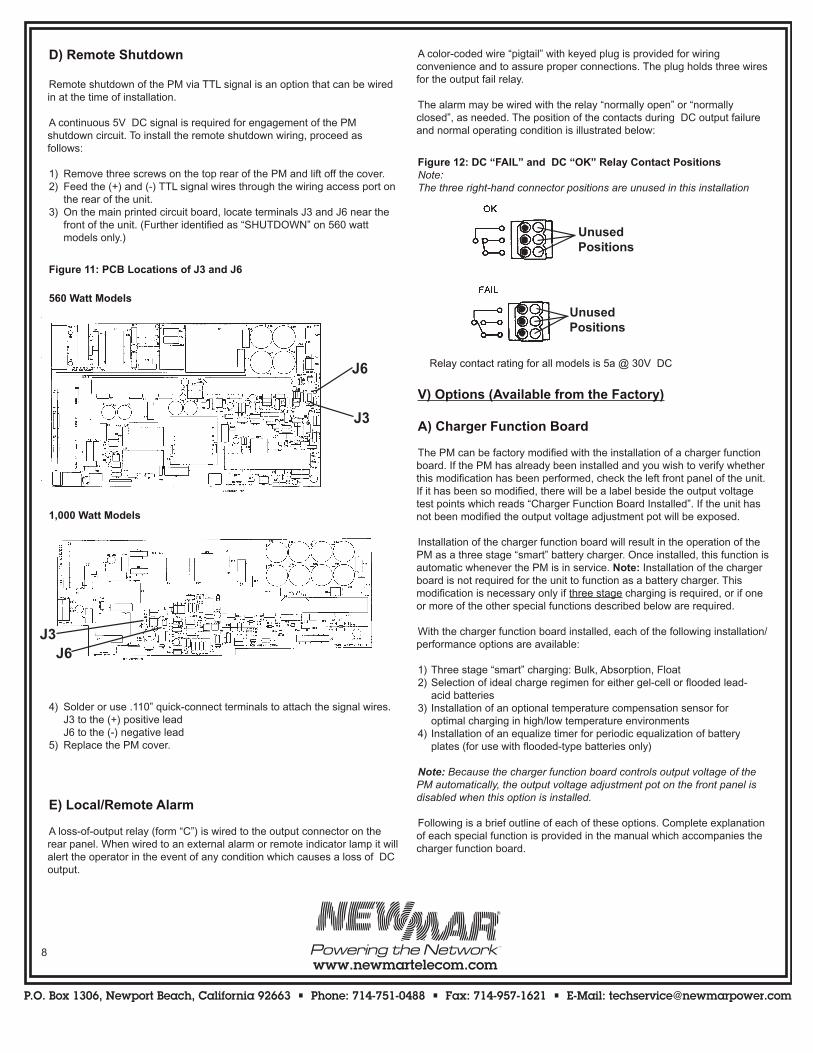
D) Remote Shutdown
Remote shutdown of the PM via TTL signal is an option that can be wired in at the time of installation.
A continuous 5V DC signal is required for engagement of the PM shutdown circuit. To install the remote shutdown wiring, proceed as follows:
1) Remove three screws on the top rear of the PM and lift off the cover.2) Feed the (+) and (-) TTL signal wires through the wiring access port on the rear of the unit.3) On the main printed circuit board, locate terminals J3 and J6 near the front of the unit. (Further identified as “SHUTDOWN” on 560 watt models only.)
Figure 11: PCB Locations of J3 and J6
560 Watt Models
1,000 Watt Models
4) Solder or use .110” quick-connect terminals to attach the signal wires. J3 to the (+) positive lead J6 to the (-) negative lead5) Replace the PM cover.
E) Local/Remote Alarm
A loss-of-output relay (form “C”) is wired to the output connector on the rear panel. When wired to an external alarm or remote indicator lamp it will alert the operator in the event of any condition which causes a loss of DC output.
A color-coded wire “pigtail” with keyed plug is provided for wiring convenience and to assure proper connections. The plug holds three wires for the output fail relay.
The alarm may be wired with the relay “normally open” or “normally closed”, as needed. The position of the contacts during DC output failure and normal operating condition is illustrated below:
Figure 12: DC “FAIL” and DC “OK” Relay Contact PositionsNote: The three right-hand connector positions are unused in this installation
Relay contact rating for all models is 5a @ 30V DC
V) Options (Available from the Factory)
A) Charger Function Board
The PM can be factory modified with the installation of a charger function board. If the PM has already been installed and you wish to verify whether this modification has been performed, check the left front panel of the unit. If it has been so modified, there will be a label beside the output voltage test points which reads “Charger Function Board Installed”. If the unit has not been modified the output voltage adjustment pot will be exposed.
Installation of the charger function board will result in the operation of the PM as a three stage “smart” battery charger. Once installed, this function is automatic whenever the PM is in service. Note: Installation of the charger board is not required for the unit to function as a battery charger. This modification is necessary only if three stage charging is required, or if one or more of the other special functions described below are required.
With the charger function board installed, each of the following installa tion/performance options are available:
1) Three stage “smart” charging: Bulk, Absorption, Float2) Selection of ideal charge regimen for either gel-cell or flooded lead- acid batteries3) Installation of an optional temperature compensation sensor for optimal charging in high/low temperature environments4) Installation of an equalize timer for periodic equalization of battery plates (for use with flooded-type batteries only)
Note: Because the charger function board controls output voltage of the PM automatically, the output voltage adjustment pot on the front panel is disabled when this option is installed.
Following is a brief outline of each of these options. Complete explanation of each special function is provided in the manual which accompanies the charger function board.
J3
J6
J3J6
UnusedPositions
UnusedPositions
UnusedPositions
UnusedPositions
P.O. Box 1306, Newport Beach, California 92663 • Phone: 714-751-0488 • Fax: 714-957-1621 • E-Mail: [email protected]
www.newmartelecom.com
P.O. Box 1306, Newport Beach, California 92663 • Phone: 714-751-0488 • Fax: 714-957-1621 • E-Mail: [email protected]
www.newmartelecom.com9
Three Stage ChargingThree stage charging is often recommended by battery manufacturers for allowing the fastest possible recharge time without loss of batteries’ electrolyte (gel or liquid) which may be caused by sustained charging at higher voltages. This three-stage regimen, Bulk, Absorption and Float, may contribute to longer battery life. Contact the battery manufacturer if you have questions about the necessity of charging the batteries using the three stage system.
Gel-Cell/Lead Acid Selector SwitchAccording to most battery manufacturers, the ideal charge regimen for gel-cell and wet or flooded lead acid batteries differs somewhat. The ideal charge/float regimen has been programmed into the PM charger board for either sealed gel-cell or flooded lead acid batteries. With the charger function board installed gel cell/lead acid battery selection may be made with a slide switch mounted on the board.
Temperature Compensation OptionBecause low battery temperature increases resistance to charging and high battery temperature reduces impedance, requiring a lower charge voltage, the ideal charging voltage will vary depending on the temperature of the battery’s environment when it is being charged. With the charger function board installed, the installer may then also install an optional remote temperature sensor. The remote sensor will signal the PM to fine tune its output voltage so that it is properly matched to the temperature of the battery/battery environment.
Equalize Timer OptionSome manufacturers of flooded lead-acid batteries recommend a charg-ing process known as equalization for extended battery life. This process involves occasionally charging a flooded lead-acid battery at a very high voltage for a short period of time in order to completely de-sulfate each of the battery plates, essentially equalizing their voltage. With the charger function board installed, the installer may choose to wire in this option at the time of installation.
B) DC Quick Connect Wiring Kit
Note: This option is available only for systems which incorporate the NEWMAR Power Function Manager. For complete information on this product, please contact the factory.
A DC wiring harness quick connect kit is available from NEWMAR which simplifies parallel wiring installation of multiple Power Modules with the Power Function Manager and facilitates “hot change-out” of modules for repair or replacement.
The kit consists of two wiring harness; one for positive and negative DC output wiring, another for alarm contact wiring. Wires are pre-cut to proper length, all necessary connectors are installed and the bundles are neatly tie-wrapped into proper position for a simple and professional installation.
For more information, or to order the quick connect kit, please contact the factory and specify the number of PM’s (2-6) in the system being installed. Model QCK-3: 1-3 PM’s. Model QCK-6: 4-6 PM’s.
C) AC Transient Suppressor
For communication sites which are subject to “dirty” AC voltage with line transients or spikes, a commercially available AC transient suppressor may be required.
The suppressor provides continuous bi-polar, bi-directional, non-inter-rupting protection for both the PM and load from damaging high voltage transients. It is installed in-line with AC input to the PM. Status indicators verify input and “PROTECTED” conditions and alarm contacts indicate when the unit has tripped and equipment is in the unprotected mode. Two models are available for 115V and 230V applications. Contact the factory for more information on how to obtain this transient suppressor.
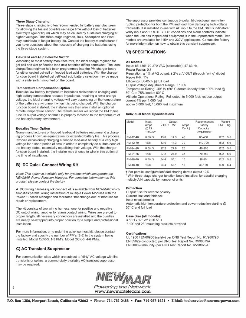
VI) SPECIFICATIONS
All ModelsInput: 85-135/170-270 VAC (selectable), 47-63 Hz.Power Factor: 0.7Regulation: ± 1% at V2 output; ± 2% at V OUT (through “oring” diode)Ripple P-P: 1%Efficiency: 80-85% @ full loadOutput Voltage Adjustment Range: ± 10 %Temperature Rating: -40° to +60° C derate linearly from 100% load @ 50° C to 75% load at 60° CAltitude Operational Rating: Full output to 5,000 feet; reduce output current 4% per 1,000 feetabove 5,000 feet; 10,000 feet maximum
Individual Model Specifications
† For parallel configuration/load sharing derate output 10%* With three-stage charger function board installed; for parallel charging multiply A/H capacity by number of units
ProtectionOutput fuse for reverse polarityCurrent limit and foldbackInput circuit breakerAutomatic high temperature protection and power reduction starting @ 50° C and full load
Case Size (all models):3.5” H x 17” W* x 20.5” D * 19” and 23” mounting brackets provided
CertificationsUL 1950 / EN60950 (safety) per DNB Test Report No. RV98079BEN 55022(conducted) per DNB Test Report No. RV98079AEN 50082(Immunity) per DNB Test Report No. RV98079A
Model Input Output Recommended Weight Amps V OUT V2 Amps Battery Lbs Kg. @ F.L. Cont.† Capacity 115/230V (Amp/Hours)*
PM-12-40 8.5/4.3 13.6 14.3 40 80-400 12.2 5.5
PM-12-70 16/8 13.6 14.3 70 140-700 15.2 6.9
PM-24-20 8.5/4.3 27.2 27.9 20 40-200 12.2 5.5
PM-24-35 16/8 27.2 27.9 35 70-350 15.2 6.9
PM-48-10 8.5/4.3 54.4 55.1 10 18-90 12.2 5.5
PM-48-18 16/8 54.4 55.1 18 36-180 14.0 6.4
P.O. Box 1306, Newport Beach, California 92663 • Phone: 714-751-0488 • Fax: 714-957-1621 • E-Mail: [email protected]
www.newmartelecom.com10
A. No output current
B. PM repeatedly trips input circuit breaker with no battery or load connected
C. Reverse polarity battery connection to PM has caused PM to stop charging
D. High output voltage measured across “V OUT” terminals
E. Batteries connected to PM overcharging
1. Using a voltmeter, confirm AC input volt age. Check input connections. Confirm AC input select switch is in correct position (560 watt models) or correct AC connector/adap tor is installed (1,000 watt models).
2. Reduce DC load and/or determine cause of over temperature condition.
3. Clear or replace clogged fan filter. Remove fan obstruction, or replace fan if necessary. (See section IV-D, Cooling Fans)
4. Replace blown fuse (See section IV-B, DC Output.)
5. Return to place of purchase for repair/re-placement or contact NEWMAR for return authorization.
1. Set AC input select switch to 230V position or install 230V connector/adaptor. Note: 115V MOV (RV1) may be damaged by incorrect AC voltage application. If so, it must be replaced by a qualified technician. If breaker continues to trip, contact factory.
2. Return to place of purchase for repair/re-placement or contact NEWMAR for return authorization.
Replace output fuse. If fuse blows again, return to place of purchase for repair/re placement or contact NEWMAR for return authorization.
Check for tight connection of charging leads from PM to batteries.
1. Move positive output wire from “V2” position to “V OUT” position.
2. Lower output voltage (See section IV-B, DC Output.) to battery manufacturer’s recommended charging voltage
VII) Troubleshooting
Condition Solution Possible Cause
1. PM not receiving AC input voltage or is not receiving correct input voltage
2. PM limiting its output due to overload or ambient over temperature condition
3. One or both fans not operating properly, or filter clogged, causing over temperature condition and PM power reduction
4. Blown output fuse
5. Defective Power Module
1. AC input select switch set to 115V (560 watt models) or 115V connector/adaptor installed (1,000 watt models) while 230V is being applied
2. Internal short
DC output fuse and possibly other compo nents blown
Batteries not connected to PM. It is normal to read 1/2 volt higher across “V OUT” terminals with no battery connected
1. Batteries connected to “V2” output terminals. “V2” output is approximately .7 volt higher than “V OUT” output
2. Output voltage adjusted too high
Recommended