We know how
TECHNIK
PneumaticConveying
About
Contents
Technikum 3
Plant design 4
FLUIDCON 6 Type 1: Pressure vessel conveyor 8
Type 2: X-Pump 10
Type 3: Airlift 12
Type 4: Blow feeder 14
Type 5: Jet feeder 15
Claudius Peters is one of the world’s leading
suppliers of pneumatic systems for the conveying
of dry bulk materials.
With experience in the handling and analysis of
over 13,000 different types of bulk solid,
Claudius Peters can determine the precise
conveying procedure for any requirement.
Claudius Peters’ service includes delivery of a
complete plant, from examination of bulk
solids through selection of conveying system
with auxiliary components to installation and
plant commissioning.
Design of required pneumatic equipment (includ-
ing bulk solid feeders, air supply equipment,
conveying pipelines and the air/solid classifiers)
can come from a client’s specification or from
Claudius Peters’ own material sample analysis.
Since its founding in 1906, Claudius Peters has become one of the world’s
most respected engineering houses and an innovative world leader. Its German
engineering excellence continues to set benchmarks for the design, manufacture
and commissioning of materials handling and processing systems for the
gypsum, cement, coal, alumina, steel and bulk-handling industries.
From conception and installation through to commissioning and after-sales
support, Claudius Peters provides world-class service to the world’s biggest
bulk materials producers.
The Claudius Peters Group GmbH is headquartered in Buxtehude near Hamburg,
Germany, with regional offices in the Americas, Asia and Europe.
Claudius Peters’ headquarters, Buxtehude, Germany.
2 2
pneumatic conveying technik
Technikum
Extensive testing, backed by years of experience
enables Claudius Peters to design and produce
conveying systems which combine high reliability
with minimal power consumption.
With conveying lines up to 5km long and a wide
range of pipe diameters, the laboratory enables
the design and supply of systems which have
been calculated for optimal process, cost and
operating parameters.
In the Technikum, conveying procedures can
be tested for any load, gas velocity, conveying
pressure and conveying distance.
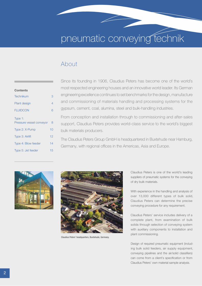
The Claudius Peters Technikum (Technical Center) offers clients a laboratory
with facility to test all bulk solid conveying systems.
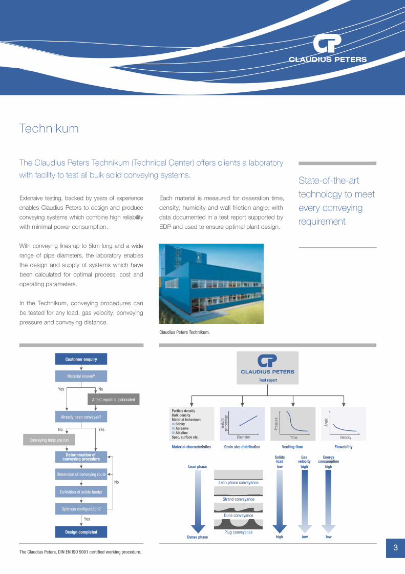
Customer enquiry
Material known?
A test report is elaborated
Conveying tests are run
Already been conveyed?
Dimension of conveying route
Definition of solids feeder
Optimun configuration?
Determination of conveying procedure
Design completed
Yes No
Yes
Yes
No
No
State-of-the-art technology to meet every conveying requirement
Test report
Grain size distributionMaterial characteristics Venting time Flowability
Particle densityBulk densityMaterial behaviour:� Sticky� Abrasive� AlkalineSpec, surface etc. Time
Pres
sure
Velocity
Angl
e
Diameter
Wei
ght
perc
enta
ge
Dense phase
Lean phase conveyance
Strand conveyance
Dune conveyance
Plug conveyancelow lowhigh
Lean phase low high high
Solidsload
Gasvelocity
Energyconsumption
The Claudius Peters, DIN EN ISO 9001 certified working procedure.
Claudius Peters Technikum.
Each material is measured for deaeration time,
density, humidity and wall friction angle, with
data documented in a test report supported by
EDP and used to ensure optimal plant design.
3
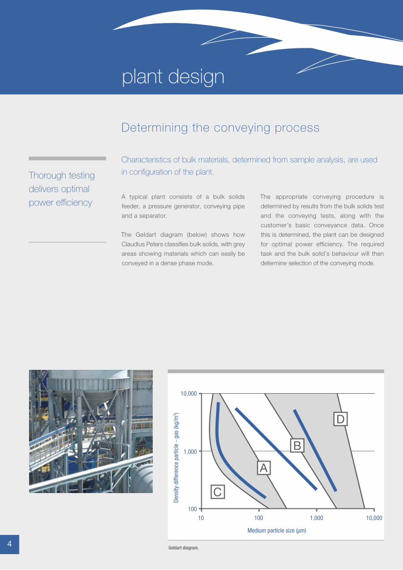
A typical plant consists of a bulk solids
feeder, a pressure generator, conveying pipe
and a separator.
The Geldart diagram (below) shows how
Claudius Peters classifies bulk solids, with grey
areas showing materials which can easily be
conveyed in a dense phase mode.
Characteristics of bulk materials, determined from sample analysis, are used
in configuration of the plant.
Determining the conveying process
The appropriate conveying procedure is
determined by results from the bulk solids test
and the conveying tests, along with the
customer’s basic conveyance data. Once
this is determined, the plant can be designed
for optimal power efficiency. The required
task and the bulk solid’s behaviour will then
determine selection of the conveying mode.
100
10,000
1,000
10 100 1,000 10,000
Medium particle size (μm)
Dens
ity d
iffer
ence
par
ticle
- g
as (k
g/m
3 )
C
A
B
D
Geldart diagram.
Thorough testing delivers optimal power efficiency
4 4
plant design
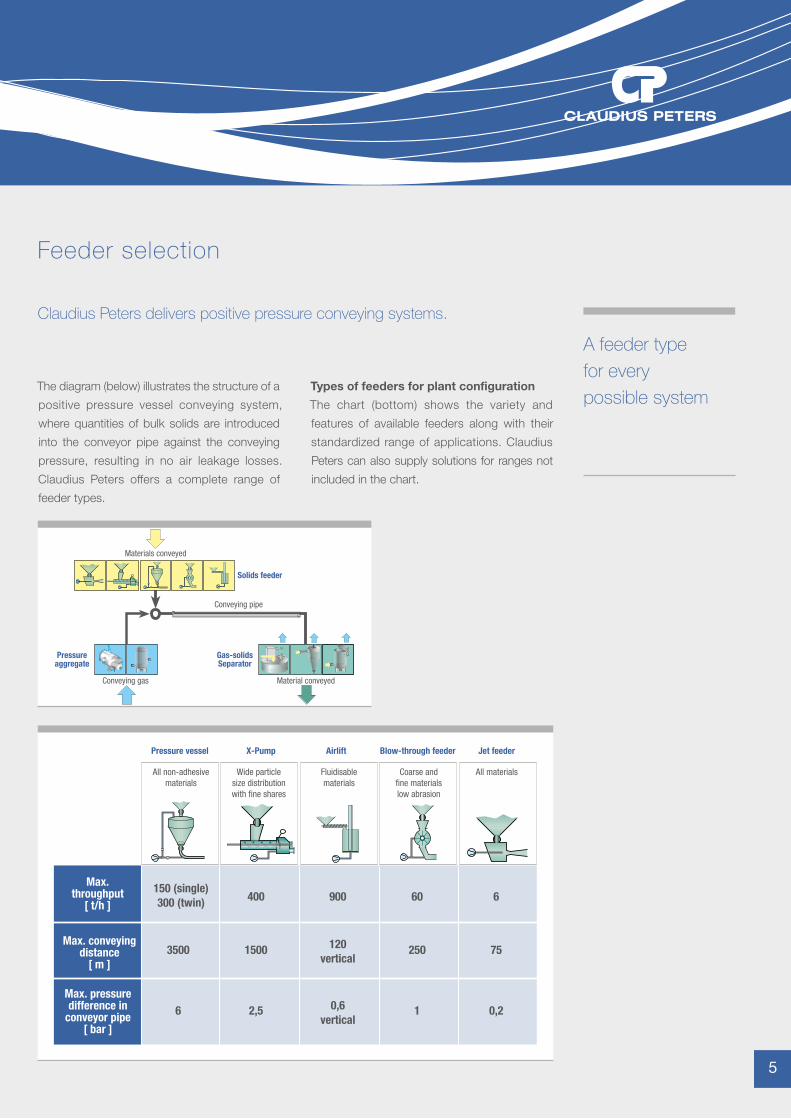
The diagram (below) illustrates the structure of a
positive pressure vessel conveying system,
where quantities of bulk solids are introduced
into the conveyor pipe against the conveying
pressure, resulting in no air leakage losses.
Claudius Peters offers a complete range of
feeder types.
Claudius Peters delivers positive pressure conveying systems.
Feeder selection
Materials conveyed
Conveying gas Material conveyed
Conveying pipe
Solids feeder
Gas-solidsSeparator
Pressureaggregate
Pressure vessel
All non-adhesivematerials
Fluidisablematerials
Coarse andfine materialslow abrasion
All materialsWide particlesize distributionwith fine shares
X-Pump Airlift Blow-through feeder Jet feeder
150 (single)300 (twin) 400 900 60 6
15003500 120vertical
250 75
2,56 0,6vertical
1 0,2
Max.throughput
[ t/h ]
Max. conveyingdistance
[ m ]
Max. pressuredifference in
conveyor pipe[ bar ]
A feeder type for every possible system
Types of feeders for plant configuration
The chart (bottom) shows the variety and
features of available feeders along with their
standardized range of applications. Claudius
Peters can also supply solutions for ranges not
included in the chart.
5
Pneumatic conveying, with considerably lower power consumption
Additionally, FLUIDCON provides a dense phase
system with increased bulk material load and
can be used to convey all fine bulk solids that
can be fluidized with low air velocities, expanding
homogeneously during the process. Depending
on the transport pipe routing chosen, it can
substantially reduce power consumption
About FLUIDCON
FLUIDCON is a conveyor pipe that can
partially or completely fluidize material over
the horizontal length of the pipe (the aeroslide
principle). The air is used to fluidize but not
transport the material.
Advantages of FLUIDCON
n Reduced operating costs. Substantially less energy consumption. Compared to conventional pneumatic conveying
n High availability. The system is easily started or restarted even when solids remain in the conveying line
n Gentle material handling. This is due to lower conveying velocities starting at approximately 2-3m/s and ending at approximately 5-10m/s
n Alternative feed systems. With a reduction in the conveying pressure, Claudius Peters X-pumps (screw pumps) can be installed instead of conventional pressure vessels to ensure savings in height and capital costs
To transport the material, transport air travels
perpendicular to the fluidized air and passes in
an axial direction. The pressure loss of the
transport air flow substitutes for the inclination
of the aeroslide. The aeroslide principle turns
the bulk solids into a fluid state with minimal
internal friction and ensures that it remains
fluidized away from the bottom of the pipe and
in the gas flow. These optimum conveying
conditions allow the transportation of solids
with lowest axial driving gas velocities in the
feed point and acceleration section of the pipe.
It is therefore possible to convey materials with
the FLUIDCON system using minimal
differential pressure through uphill inclines of
up to 30°.
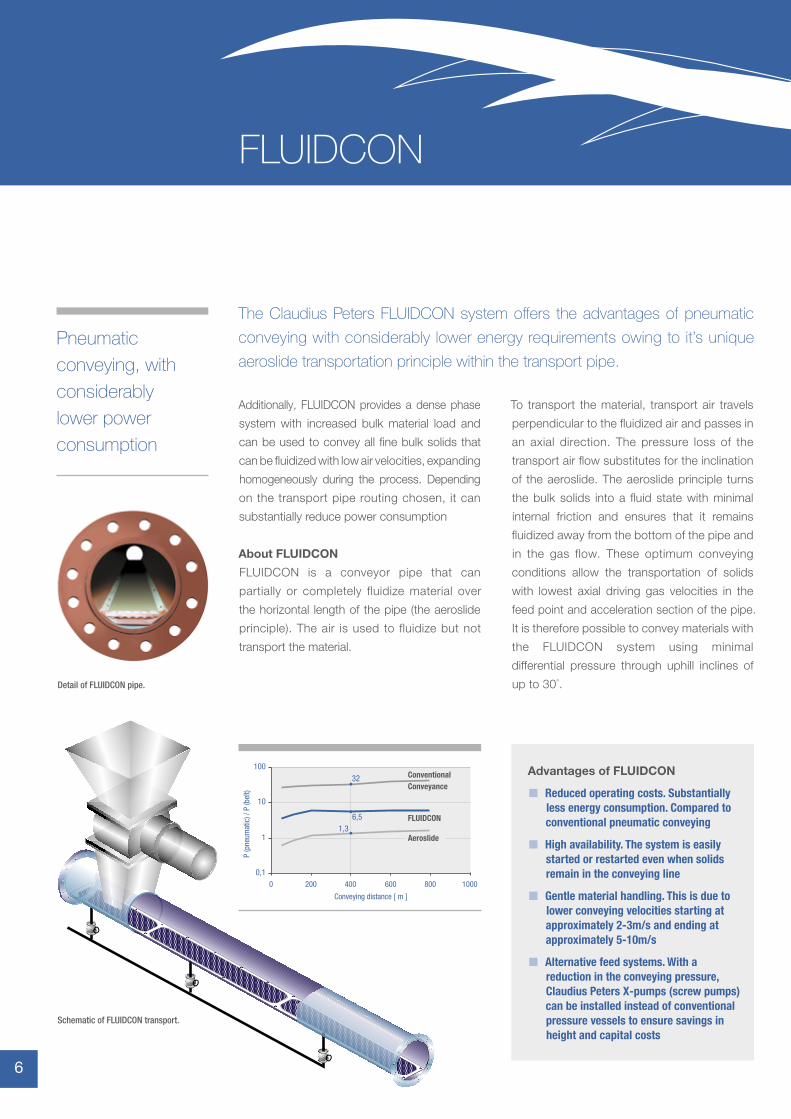
Schematic of FLUIDCON transport.
Detail of FLUIDCON pipe.
0,1
1
10
100
0 200 400 600 800 1000
Conveying distance [ m ]
Aeroslide
ConventionalConveyance
FLUIDCON
P (p
neum
atic
) / P
(bel
t)
32
6,51,3
The Claudius Peters FLUIDCON system offers the advantages of pneumatic
conveying with considerably lower energy requirements owing to it’s unique
aeroslide transportation principle within the transport pipe.
6 6
FLUIDCON
The Claudius Peters FLUIDCON System has
proven to be a valuable alternative in bulk
materials handling applications.
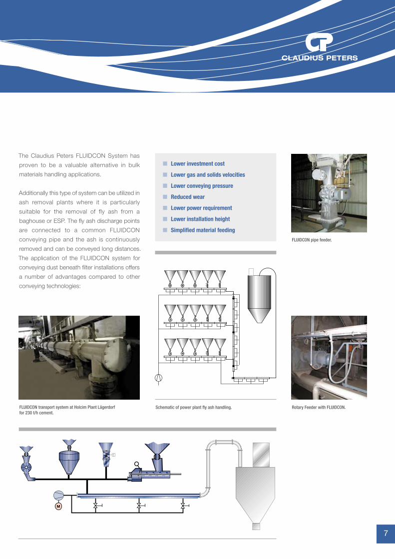
Additionally this type of system can be utilized in
ash removal plants where it is particularly
suitable for the removal of fly ash from a
baghouse or ESP. The fly ash discharge points
are connected to a common FLUIDCON
conveying pipe and the ash is continuously
removed and can be conveyed long distances.
The application of the FLUIDCON system for
conveying dust beneath filter installations offers
a number of advantages compared to other
conveying technologies:
n Lower investment cost
n Lower gas and solids velocities
n Lower conveying pressure
n Reduced wear
n Lower power requirement
n Lower installation height
n Simplified material feeding
FLUIDCON pipe feeder.
Schematic of power plant fly ash handling. Rotary Feeder with FLUIDCON.FLUIDCON transport system at Holcim Plant Lägerdorf for 230 t/h cement.
M
7
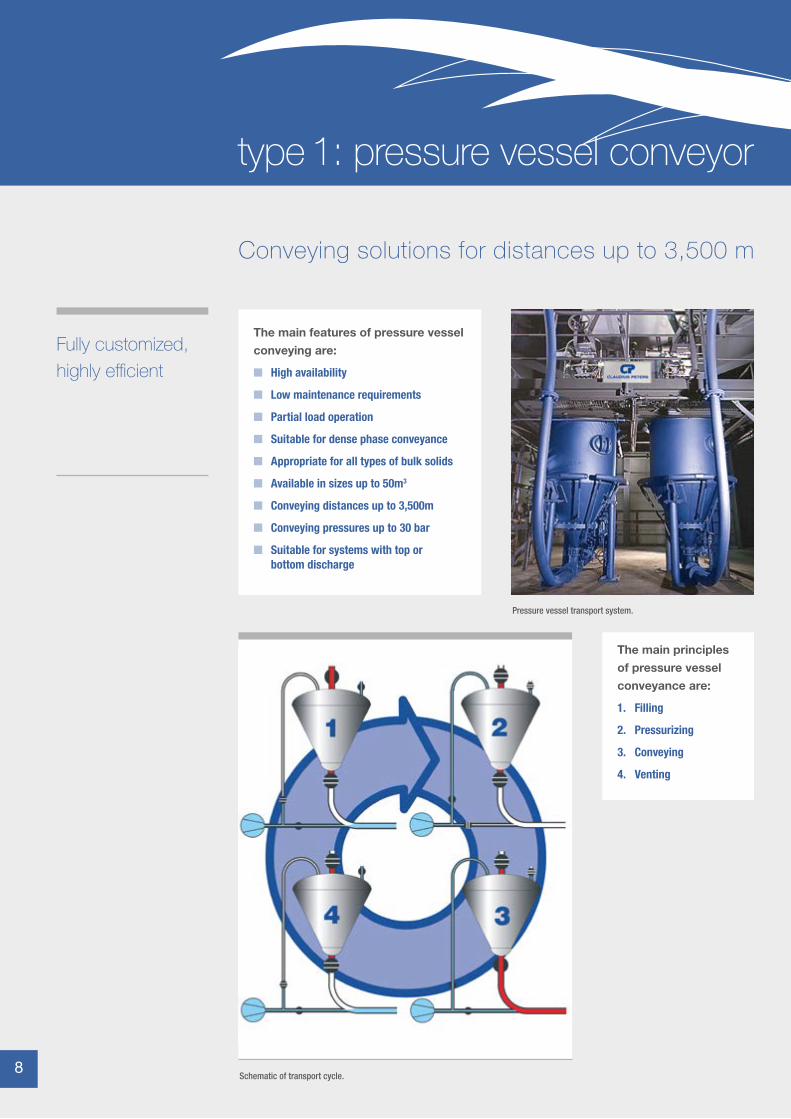
The main features of pressure vessel conveying are:
n High availability
n Low maintenance requirements
n Partial load operation
n Suitable for dense phase conveyance
n Appropriate for all types of bulk solids
n Available in sizes up to 50m3
n Conveying distances up to 3,500m
n Conveying pressures up to 30 bar
n Suitable for systems with top or bottom discharge
The main principles of pressure vessel conveyance are:
1. Filling
2. Pressurizing
3. Conveying
4. Venting
Conveying solutions for distances up to 3,500 m
Fully customized, highly efficient
Pressure vessel transport system.
Schematic of transport cycle.8 8
type 1: pressure vessel conveyor
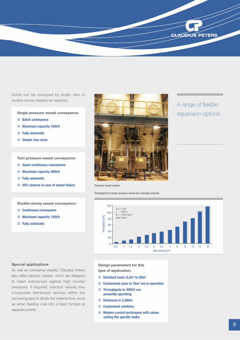
Solids can be conveyed by single, twin or
double-storey vessels as required.
Special applications
As well as conveying vessels, Claudius Peters
also offers injection vessels, which are designed
to inject substances against high counter
pressures. If required, injection vessels may
incorporate distribution devices within the
conveying pipe to divide the material flow, such
as when feeding coal into a blast furnace at
separate points.
Single pressure vessel conveyance:
n Batch conveyance
n Maximum capacity 150t/h
n Fully automatic
n Simple, low costs
Twin pressure vessel conveyance:
n Quasi-continuous conveyance
n Maximum capacity 300t/h
n Fully automatic
n 50% reserve in case of vessel failure
Double-storey vessel conveyance:
n Continuous conveyance
n Maximum capacity 150t/h
n Fully automatic
Design parameters for this type of application:
n Standard sizes: 0.2m3 to 20m3
n Customized sizes to 35m3 are in operation
n Throughputs to 300t/h are presently operating
n Distances to 3,500m
n Customized solutions
n Modern control techniques with valves suiting the specific bulks
0
20
40
60
80
100
120Δp = 3 barL = 200 m ss = 1000 kg/m3
wear class 1
0,5 1 1,5 2 2,5 3 3,5 4 6 8 12 15 20Net volume [m3]
Thro
ughp
ut [t
/h]
A range of flexible
expansion options
Pressure vessel system.
Throughput for single pressure vessel (for example cement).
9
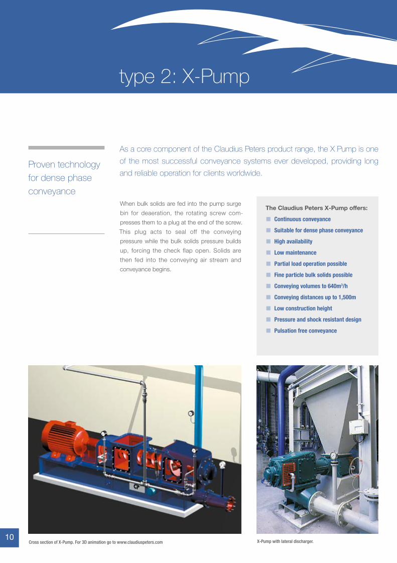
Proven technology for dense phase conveyance
The Claudius Peters X-Pump offers:
n Continuous conveyance
n Suitable for dense phase conveyance
n High availability
n Low maintenance
n Partial load operation possible
n Fine particle bulk solids possible
n Conveying volumes to 640m3/h
n Conveying distances up to 1,500m
n Low construction height
n Pressure and shock resistant design
n Pulsation free conveyance
As a core component of the Claudius Peters product range, the X Pump is one
of the most successful conveyance systems ever developed, providing long
and reliable operation for clients worldwide.
X-Pump with lateral discharger.Cross section of X-Pump. For 3D animation go to www.claudiuspeters.com
When bulk solids are fed into the pump surge
bin for deaeration, the rotating screw com-
presses them to a plug at the end of the screw.
This plug acts to seal off the conveying
pressure while the bulk solids pressure builds
up, forcing the check flap open. Solids are
then fed into the conveying air stream and
conveyance begins.
10 10
type 2: X-Pump
A feeder for dense-phase and lean-phase conveying
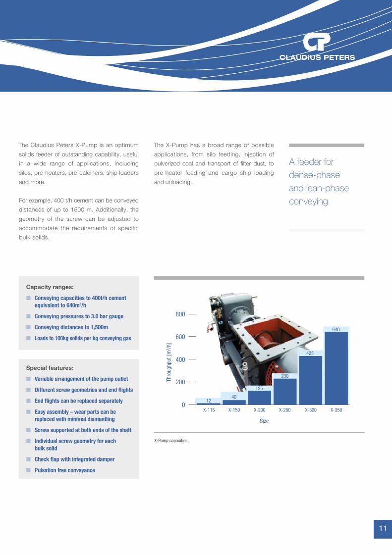
Capacity ranges:
n Conveying capacities to 400t/h cement equivalent to 640m3/h
n Conveying pressures to 3.0 bar gauge
n Conveying distances to 1,500m
n Loads to 100kg solids per kg conveying gas
Special features:
n Variable arrangement of the pump outlet
n Different screw geometries and end flights
n End flights can be replaced separately
n Easy assembly – wear parts can be replaced with minimal dismantling
n Screw supported at both ends of the shaft
n Individual screw geometry for each bulk solid
n Check flap with integrated damper
n Pulsation free conveyance
800
600
400
200
X-115 X-150 X-200 X-250 X-300 X-3500
Size
Thro
ughp
ut [m
3 /h]
1240
125
230
425
640
The Claudius Peters X-Pump is an optimum
solids feeder of outstanding capability, useful
in a wide range of applications, including
silos, pre-heaters, pre-calciners, ship loaders
and more.
For example, 400 t/h cement can be conveyed
distances of up to 1500 m. Additionally, the
geometry of the screw can be adjusted to
accommodate the requirements of specific
bulk solids.
X-Pump capacities.
The X-Pump has a broad range of possible
applications, from silo feeding, injection of
pulverized coal and transport of filter dust, to
pre-heater feeding and cargo ship loading
and unloading.
11
Vertical lift capability with a low investment cost
The Claudius Peters Airlift: a pneumatic lift that can convey solids vertically to a
maximum capacity of 1000t/h.
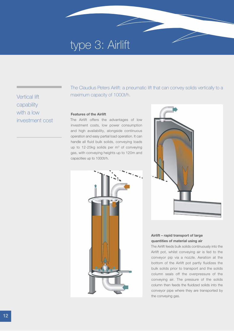
Features of the Airlift
The Airlift offers the advantages of low
investment costs, low power consumption
and high availability, alongside continuous
operation and easy partial load operation. It can
handle all fluid bulk solids, conveying loads
up to 12-25kg solids per m3 of conveying
gas, with conveying heights up to 120m and
capacities up to 1000t/h.
Airlift – rapid transport of large
quantities of material using air
The Airlift feeds bulk solids continuously into the
Airlift pot, whilst conveying air is fed to the
conveyor pip via a nozzle. Aeration at the
bottom of the Airlift pot partly fluidizes the
bulk solids prior to transport and the solids
column seals off the overpressure of the
conveying air. The pressure of the solids
column then feeds the fluidized solids into the
conveyor pipe where they are transported by
the conveying gas.
12 12
type 3: Airlift
The Claudius Peters Airlift transports material
vertically to cyclone pre-heaters or storage
silos. With throughputs to 1000t/h, the Airlift is
an efficient, high capacity conveying method.
Its specialized design, called ‘dosification’ or
DOSCON has a variety of applications:
Performance range:
n Throughputs of 10 to 1000t/h
n Conveying heights up to 120m
n Bottom aeration
n Bottom cone for coarse bulk solids
n Several feed points using two-way gates in the conveyor pipe
n Bulk solids and conveying gas can be separated by the Claudius Peters expansion vessel
n Feeding of heat exchangers
n Standby system for mechanical pre-heater feeding such as bucket elevators
n Silo feeding
n Pulsation free, precise dosing (DOSCON)
n All types of vertical transports
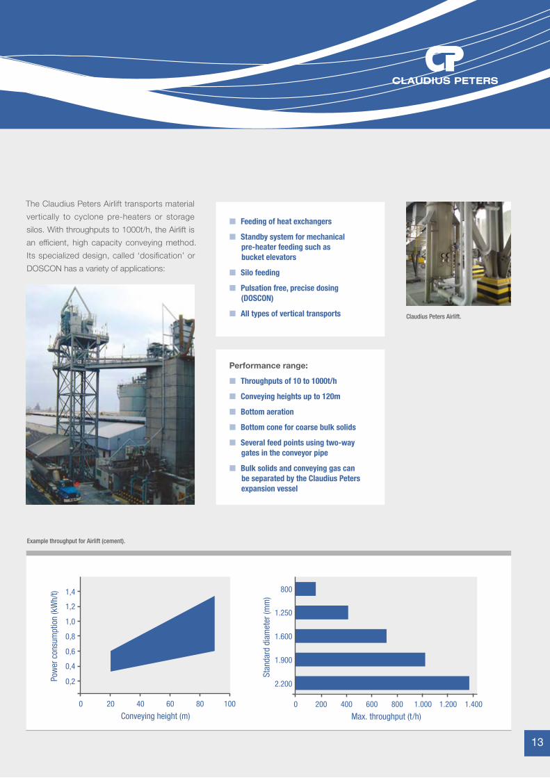
1,2
1,0
0,8
0,6
0,4
0,2
1,4
0 20 40 60 80 100
Conveying height (m)
Pow
er c
onsu
mpt
ion
(kW
h/t)
1.250
1.600
1.900
2.200
800
0 200 400 600 800 1.000 1.200 1.400
Max. throughput (t/h)
Stan
dard
dia
met
er (m
m)
Example throughput for Airlift (cement).
Claudius Peters Airlift.
13
Function of Blow Feeder system
When the bulk solid is dropped into the rotating
feeding chamber, it is blown out of the lower
chamber via lateral air connections. The bulk
solid then drops into the blow pan where it is
picked up by conveying air and transported
within the conveyor pipe.
Blow Feeder applications
As well as silo feeding and intermediate
transport applications, the Blow Feeder can
be used for filter dust return and material
return, for example bag discharge to the
packer pre-bin.
Not all types of application
demand high throughput
When average performance is required at
optimum cost efficiency, Claudius Peters
recommends the blow feeder. This feeder has
typical volume throughputs of 20-30m3/h with
a maximum of 100m3/h and is especially
suited for the transport of sticky materials.
Bulk solids with difficult flow behaviours can be handled with our feeding and
conveyance unit. The Claudius Peters Blow Feeder offers a combination of
features for all conveying procedures requiring more than simply throughput
and conveying distance specification. It offers:
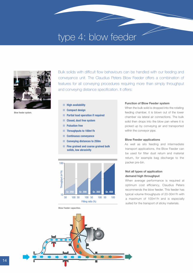
10
100
50 100
Gr. 250 Gr. 300 Gr. 350 Gr. 450
50 100 50 100 50 100
Filling ratio (%)
Thro
ughp
ut (m
3 /h)
Blow Feeder capacities.
n High availability
n Compact design
n Partial load operation if required
n Closed, dust free system
n Pulsation free
n Throughputs to 100m3/h
n Continuous conveyance
n Conveying distances to 250m
n Fine grained and coarse grained bulk solids, low abrasivity
Blow feeder system.
14 14
type 4: blow feeder
Compact design that handles all bulk solids
Of all the five available feeder types, the Claudius Peters Jet Feeder is the
most compact and offers important advantages for specific applications.
n Continuous operation
n High operational safety
n Long life times
n Low investment cost
n High solids temperature capability
n Partial load operation without modification of the conveying air flow
n Lean phase conveyance
n All bulk solids
n Closed dust free system
n Simple and space saving construction
n No movable parts in the solids flow
n Throughputs up to 6t/h
n Conveying pressures to 0.2 bar gauge
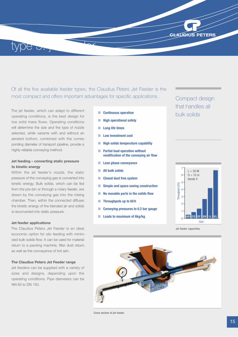
n Loads to maximum of 6kg/kg0
1
2
3
5
4
6
7L = 50 MH = 10 mbends 4
Size
Thro
ughp
ut [t
/h]
AB CD EF GH IJ KL
The jet feeder, which can adapt to different
operating conditions, is the best design for
low solid mass flows. Operating conditions
will determine the size and the type of nozzle
selected, while variants with and without an
aerated bottom, combined with the corres-
ponding diameter of transport pipeline, provide a
highly reliable conveying method.
Jet feeding – converting static pressure
to kinetic energy
Within the jet feeder’s nozzle, the static
pressure of the conveying gas is converted into
kinetic energy. Bulk solids, which can be fed
from the pre-bin or through a rotary feeder, are
drawn by the conveying gas into the mixing
chamber. Then, within the connected diffuser,
the kinetic energy of the blended air and solids
is reconverted into static pressure.
Jet feeder applications
The Claudius Peters Jet Feeder is an ideal,
economic option for silo feeding with minim-
ized bulk solids flow. It can be used for material
return to a packing machine, filter dust return,
as well as the conveyance of hot ash.
The Claudius Peters Jet Feeder range
Jet feeders can be supplied with a variety of
sizes and designs, depending upon the
operating conditions. Pipe diameters can be
NN 65 to DN 150.
Cross section of jet feeder.
Jet feeder capacities.
15
type 5: jet feeder
We know how
claudiuspeters.com
Claudius Peters Projects GmbH
Schanzenstraße 40
DE-21614 Buxtehude, Germany
T: +49 4161 706-0
Claudius Peters Technologies SAS
34 Avenue de Suisse
F-68316 Illzach, France
T: +33 3 89 31 33 00
CALCINING
COOLING
DISPATCH
DOSING
DRY BLENDING
DRYING
GRINDING
PACKING
PNEUMATIC CONVEYING
PULVERIZED FUEL SUPPLY
SILO SYSTEMS
STOCKYARD SYSTEMS
ALUMINA HANDLING SYSTEMS
MARINE POWDER HANDLING
TURNKEY PROJECTS
Claudius Peters (do Brasil) Ltda. Rua das Figueiras, 474 - 3 º andar - Edifício Eiffel - Bairro Jardim - 09080-300 - Santo André / SP, Brazil T: +55 (11) 4903 9230 E: [email protected]
Claudius Peters (China) Ltd. Unit 1706-1706, 17/F Laws Commercial Plaza, 788 Cheung Sha Wan Road, Lai Chi Kok, Kowloon, Hong Kong T: +852 2544 1848 E: [email protected]
Branch Office: 7/F, Office Block, Hong Kong Macau Centre, No. 2 Chaoyangmen Bei Da Jie, Beijing 100027, P. R. China T: +86 10 6501 3831 E: [email protected]
Claudius Peters (India) Pvt. Ltd. Unit 408, 4th Floor, Peninsula Plaza, A/16 Fun Republic Lane, Off Link Road, Andheri West, Mumbai 400 053, India T: +91 (22) 2674 0045 E: [email protected]
Claudius Peters (Italiana) srl Via Verdi 2, I-24121 Bergamo, Italy T: +39 0 35 237 196 E: [email protected]
Claudius Peters (România) S.R.L. Str. Oituz Nr. 25C, et 2, 550337 Sibiu, România T: +40 (0) 369 407 036 E: [email protected]
Claudius Peters (Asia Pacific) Pte. Ltd. 25 International Business Park, #01-65/66 German Centre, Singapore 609916 T: +65 6562 9100 E: [email protected]
Claudius Peters (Ibérica) S.A. Paseo de la Habana, 202 Bis Bj, E-28036 Madrid, Spain T: +34 91 413 36 16 E: [email protected]
Claudius Peters (UK) Ltd. Unit 10, Thatcham Business Village, Colthrop Way, Thatcham, Berkshire, RG19 4LW, United Kingdom T: +44 (0) 1635 872139 E: [email protected]
Claudius Peters (Americas) Inc. 445 W. President George Bush Highway Richardson, Texas 75080, USA T: +1 972 386 4451 E: [email protected]
CP Pneumatic Conveying Technik (GB) 08/2014 / Issue 1. Due to a policy of continued improvement, we reserve the right to change any specification without prior notice. ERRORS & OMISSIONS EXCEPTED.Printed on a Manroland R700 press.
PneumaticConveying
Recommended