motors • dr i ves • contro ls
®
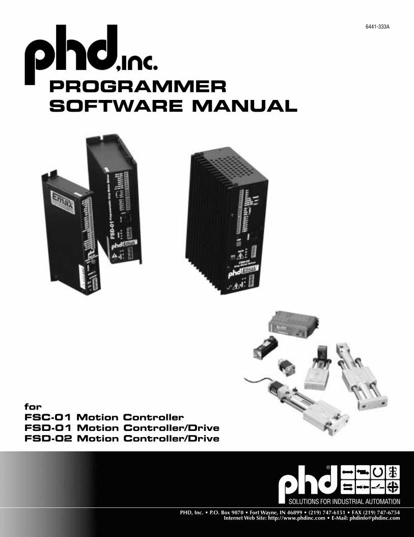
PROGRAMMERSOFTWARE MANUAL
forFSC-01 Motion ControllerFSD-01 Motion Controller/DriveFSD-02 Motion Controller/Drive
6441-333A
2SOLUTIONS FORINDUSTRIAL AUTOMATION
(800) 624-8511Web Site: http://www.phdinc.com
Table of ContentsGetting Started ..........................................................................................................3
Installing the Programming Software ................................................................................................... 4Display Settings ................................................................................................................................... 4Connecting to your PC ......................................................................................................................... 5
Programming ............................................................................................................6Which Software Version Do I Have? .................................................................................................... 7Entering Your Program ........................................................................................................................ 7Copying Instructions ............................................................................................................................ 9Inserting and Deleting Program Steps ............................................................................................... 10Setting Parameters ............................................................................................................................. 10User Defined Units ............................................................................................................................. 12
Limit Switches ........................................................................................................ 12What Happens When You Hit a Limit Switch? .................................................................................... 12Front Panel STOP Button ................................................................................................................... 13
Setting the Motor Current ........................................................................................... 13Idle Current Reduction ....................................................................................................................... 13
Microstepping ......................................................................................................... 14Jogging ................................................................................................................. 15Using the Optional MMI (Man Machine Interface-part #64725) ............................................... 16
How to display a message on the MMI .............................................................................................. 17How to pause until user presses ENTER ............................................................................................ 17How to let the user make a decision (MMI branching) ....................................................................... 18How to ask the user for a move distance ........................................................................................... 18How to get a speed from the user ...................................................................................................... 19How to get a repeat count from the user ............................................................................................ 19How to create an MMI Menu .............................................................................................................. 20
Making Your Move .................................................................................................... 21MMI Prompt ....................................................................................................................................... 21Feed to Length ................................................................................................................................... 23Feed & Set Output .............................................................................................................................. 25Feed & Return .................................................................................................................................... 26Feed to Sensor ................................................................................................................................... 27Feed to Sensor & Return .................................................................................................................... 28Feed to Position ................................................................................................................................. 29Set Abs Position ................................................................................................................................. 30Seek Home ......................................................................................................................................... 31Wait Time ........................................................................................................................................... 32Wait Input .......................................................................................................................................... 33Hand Wheel ........................................................................................................................................ 34Go To .................................................................................................................................................. 34Repeat/End Repeat ............................................................................................................................. 35Reset Repeat Loop ............................................................................................................................. 37Set Output .......................................................................................................................................... 38If Input Go To ..................................................................................................................................... 39Change Current .................................................................................................................................. 41Comment ........................................................................................................................................... 42
Command Buttons .................................................................................................... 43Download, Upload & Execute ............................................................................................................. 43Save, Open, Print & Quit .................................................................................................................... 44
3(800) 624-8511
Web Site: http://www.phdinc.comSOLUTIONS FORINDUSTRIAL AUTOMATION
Getting StartedThe PHD programming software is used in several PHD products, including the FSD-01, FSD-02 Programmable Motion Controller/Drives, and the FSC-01 Programmable Motion Controller. This manual explains how to install the PHD Windows application and how toprogram your PHD product.
For information regarding your specific PHD hardware, such as wiring and mounting, please read the hardware manual that came withthat product.
The PHD Series FS Controls features include:• Powerful, flexible, easy to use indexer.• Nonvolatile program storage.• Automatic, stand alone execution of stored program.• Connection by a simple cable to your PC for programming (cable included).• Microsoft Windows™-based software for easy set up and programming (included)• Programmable inputs for interacting with the user and other equipment.• Programmable outputs for coordinating external equipment.• Instructions for motion, triggering, branching, loops, time delays, and more.• Ability to work in user defined units such as inches, degrees, gallons, etc.• Optional man machine interface (MMI) allows operator to enter distances, speeds, loop counts, and more.
To operate your PHD product, you must do the following:• Connect a motor (for the FSC-01 Motion Controller, you’ll need a PHD FSA-01 Servo Drive).• Connect power.• Connect any inputs or outputs that you require.• Plug into your personal computer for programming.• Install our software program on your PC.
Note: This manual was prepared for the release of drive firmware version 1.54 and Windows programmingsoftware version 1.50.03.
4SOLUTIONS FORINDUSTRIAL AUTOMATION
(800) 624-8511Web Site: http://www.phdinc.com
Installing the Programming SoftwareThe PHD Programmer software comes on two 3.5" software diskettes. Before you can use the software, you must install it on your hard drive.
To run the PHD Programmer software, you must have a computer with the following requirements:• IBM compatible 386, 486, Pentium or better CPU. A Pentium is recommended for best performance.• Microsoft Windows 3.1, Windows 95, Windows 98, or Windows NT• At least 8 MB memory (16 MB or more will make the software run much faster)• 4 MB available hard drive space• VGA monitor or better. 16 bit color setting recommended (65,535 colors, sometimes called High Color)• Mouse or other input device• 3.5" floppy disk drive• A nine pin serial port must be available, preferably COM1.
The software installation is highly automated, like most Windows programs, so the process is simple:• Put Disk 1 in your 3.5" drive.• From the Windows Program Manager, select Run from the File menu. (In Windows 95/98 and NT 4.0, choose Run from the Start
menu.)• If your 3.5" drive is drive A, then enter the command line A:\setup. If your drive is B, type B:\setup.• The setup program will guide you through the rest of the installation.
If you encounter errors during installation, it is usually due to lack of memory or conflicts with other programs that are already runningon your PC. If you experience an error while installing the programming software, quit all other Windows applications and try again.Holding down the ALT key and pressing TAB will show you all the programs currently running on your PC. Laptop computers generallypresent the biggest challenge to installation, as they often come preloaded with programs that automatically execute on startup such asMicrosoft Office and battery managers. Furthermore, laptops usually have the least memory.
The programming software will install more easily and run much faster if you have more memory. We recommend 8 megabytes of RAMon a Windows 3.1 system, and 16 megabytes with Windows 95.
Several example programs are installed with your programming software. It’s a good idea to load some of the examples and look atthem; they may help you with your own application.
Display SettingsThe PHD Programmer Software works well with any display resolution. At 640 x 480, the PHD Programmer window will exactly fill yourscreen. At higher resolutions, like 800 x 600 or 1024 x 768, there will be room left over on the screen for other applications, or to expandthe PHD Programmer window so you can see more program lines. 16 bit color setting is recommended (65,535 colors, sometimescalled High Color)
Information in the program window will not display correctly if your display is set for “Large Fonts.” Please use the “Small Fonts” settingwhen running the PHD Programmer software. The display settings are found under “Start...Control Panels” in Windows 95, and in the“Main...Control Panels” program group in Windows 3.1.
5(800) 624-8511
Web Site: http://www.phdinc.comSOLUTIONS FORINDUSTRIAL AUTOMATION
Connecting to your PC• Locate your computer within 6 feet of the PHD hardware.• Your PHD product was shipped with a black adapter plug. It has a telephone style jack at one end and a larger 9 pin connector at the
other. Plug the large end into the COM1 serial port of your PC. Secure the adapter with the screws on the sides. If the COM1 port onyour PC is already used by something else, you may use the COM2 port for the PHD Indexer. On some PCs, COM2 will have a 25 pinconnector that does not fit the black adapter plug. If this is the case, and you must use COM2, you will have to purchase a 25 to 9 pinserial adapter at your local computer store.
• Your PHD Series FS Controller was also shipped with a 7 foot telephone line cord. Plug one end into the adapter we just attached toyour PC, and the other end into the RS232 jack on your PHD Indexer.
Never connect the PHD Motion Controller or Motion Controller/Drive to a telephone circuit. It usesthe same connectors and cords as telephones and modems, but thevoltages are not compatible.
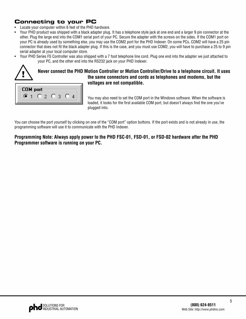
You may also need to set the COM port in the Windows software. When the software isloaded, it looks for the first available COM port, but doesn’t always find the one you’veplugged into.
You can choose the port yourself by clicking on one of the “COM port” option buttons. If the port exists and is not already in use, theprogramming software will use it to communicate with the PHD Indexer.
Programming Note: Always apply power to the PHD FSC-01, FSD-01, or FSD-02 hardware after the PHDProgrammer software is running on your PC.
!

6SOLUTIONS FORINDUSTRIAL AUTOMATION
(800) 624-8511Web Site: http://www.phdinc.com
ProgrammingYou may have noticed that the PHD Motion Controller or Motion Controller/Drive doesn’t have any switches or knobs on the front panel.There are also no jumpers inside. Just about everything you want the Series FS Controls to do is controlled by software. The PHDProgrammer software that comes with the Series FS Controls allows you to set the motor current, the step resolution, jogging param-eters, and limit switch polarity. It also helps you write complex motion control and machine interaction programs.
The Series FS Controls have a user program capacity of 100 lines. In this space, you can design one or more motion and machinecontrol programs. 20 commands or instructions are available for this purpose.
Six of the instructions involve pure motion: Feed to Length, Feed & Set Output and Feed & Return are fixed distance moves. Feed toPosition is a move to an absolute position. Feed to Sensor and Feed to Sensor & Return move relative to a sensor that is wired to one ofthe inputs. Seek Home searches for a home sensor, “bouncing off” the limits if necessary to find it.
Two instructions handle timing: Wait Time, which causes your program to stop for a specified amount of time. Wait Input waits for oneof the inputs to reach a specified state before continuing the program.
Five instructions control program flow. Go To makes the program jump to a particular line. If Input jumps to a line if one of the inputsmeets a specified condition, otherwise, the program just goes on to the next line. Repeat and End Repeat set up a loop wherein you canrepeat the same instructions many times. If your program terminates a Repeat loop before it’s finished (using an If Input instruction) youcan reset the loop count with a Reset Repeat Loop instruction.
One instruction, Set Output, allows you to signal other equipment that you have reached a particular place in your program.
Using the MMI Prompt instruction with the optional MMI (man-machine interface or operator panel), the operator can enter distances,speeds and repeat loop counts on a keypad. The drive can also display messages for the operator, pause the program until the operatorpresses the ENTER button, or ask the user to make a decision and respond by pressing the YES key or NO key.
A Comment instruction allows you to leave notes in your program so that it’s easier to understand.
Set Absolute Position lets you define the present motor position in absolute terms.
Change Current gives you more control over the motor current - turning the current off, resuming the previous level, or defining a newcurrent setting - anywhere in the program.
Hand Wheel lets the user position the motor and load precisely using a CNC hand wheel.
By combining the 20 instructions in different ways, you can construct a nearly infinite variety of useful programs and motion profiles.Before entering your program, you’ll want to spend a little time thinking about how to accomplish your objective. Then, once you have aclear idea of what to do, you can begin entering the instructions and parameters.
7(800) 624-8511
Web Site: http://www.phdinc.comSOLUTIONS FORINDUSTRIAL AUTOMATION
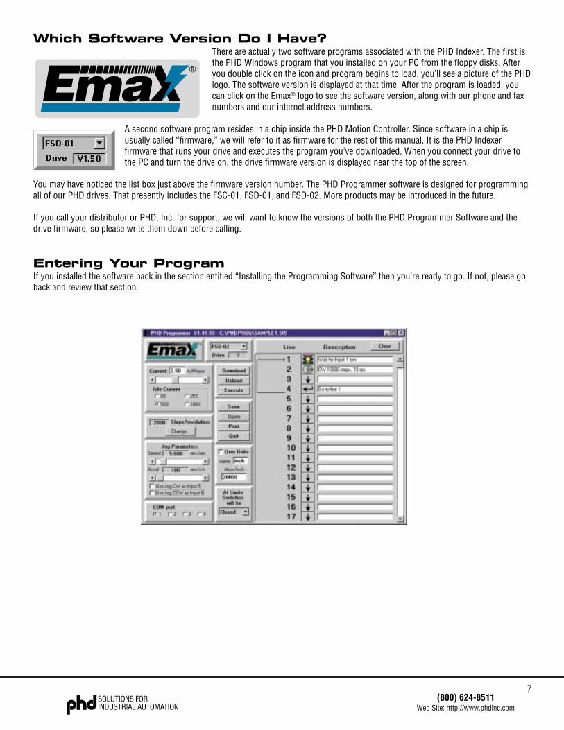
Which Software Version Do I Have?There are actually two software programs associated with the PHD Indexer. The first isthe PHD Windows program that you installed on your PC from the floppy disks. Afteryou double click on the icon and program begins to load, you’ll see a picture of the PHDlogo. The software version is displayed at that time. After the program is loaded, youcan click on the Emax® logo to see the software version, along with our phone and faxnumbers and our internet address numbers.
A second software program resides in a chip inside the PHD Motion Controller. Since software in a chip isusually called “firmware,” we will refer to it as firmware for the rest of this manual. It is the PHD Indexerfirmware that runs your drive and executes the program you’ve downloaded. When you connect your drive tothe PC and turn the drive on, the drive firmware version is displayed near the top of the screen.
You may have noticed the list box just above the firmware version number. The PHD Programmer software is designed for programmingall of our PHD drives. That presently includes the FSC-01, FSD-01, and FSD-02. More products may be introduced in the future.
If you call your distributor or PHD, Inc. for support, we will want to know the versions of both the PHD Programmer Software and thedrive firmware, so please write them down before calling.
Entering Your ProgramIf you installed the software back in the section entitled “Installing the Programming Software” then you’re ready to go. If not, please goback and review that section.
®
8SOLUTIONS FORINDUSTRIAL AUTOMATION
(800) 624-8511Web Site: http://www.phdinc.com
To activate the software, click on the Start button, then Programs...PHD Programmer. If you have Windows 3.1, locate the PHD icon.Usually, it appears in the program group “PHD Programmer.” Double click on the icon to run the software. The main programmingwindow will soon appear, as shown above. The title bar will display the PHD Programmer software version.
If you have a PHD Motion Controller or Motion Controller/Drive connected to the PC, turn it on now. After you apply power, your com-puter should beep. The “Drive” box will display the version number of the PHD Indexer firmware that’s in your drive.
If you don’t have any PHD hardware connected to your PC, you can still write programs. Before you begin, you should select the appro-priate PHD device (FSD-01, FSD-02, or FSC-01) from the list box above the word drive. That way you will have access to the specificfeatures of the hardware you plan to use.
Let’s enter a simple program. Most programs will begin with the instruction Wait Input. That way when you first turn on the Series FSController, it doesn’t do anything until you tell it to. We’ll put a Wait Time instruction on the first line.
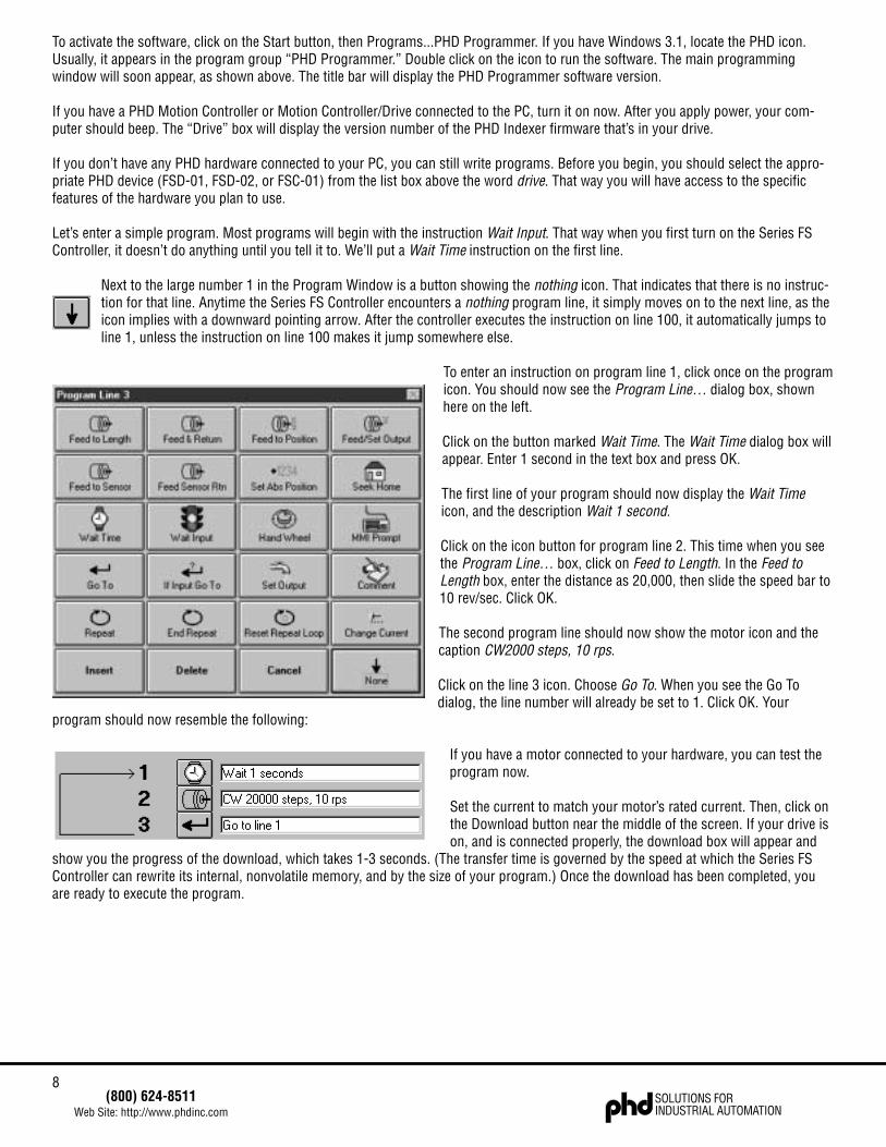
Next to the large number 1 in the Program Window is a button showing the nothing icon. That indicates that there is no instruc-tion for that line. Anytime the Series FS Controller encounters a nothing program line, it simply moves on to the next line, as theicon implies with a downward pointing arrow. After the controller executes the instruction on line 100, it automatically jumps toline 1, unless the instruction on line 100 makes it jump somewhere else.
To enter an instruction on program line 1, click once on the programicon. You should now see the Program Line… dialog box, shownhere on the left.
Click on the button marked Wait Time. The Wait Time dialog box willappear. Enter 1 second in the text box and press OK.
The first line of your program should now display the Wait Timeicon, and the description Wait 1 second.
Click on the icon button for program line 2. This time when you seethe Program Line… box, click on Feed to Length. In the Feed toLength box, enter the distance as 20,000, then slide the speed bar to10 rev/sec. Click OK.
The second program line should now show the motor icon and thecaption CW2000 steps, 10 rps.
Click on the line 3 icon. Choose Go To. When you see the Go Todialog, the line number will already be set to 1. Click OK. Your
program should now resemble the following:
If you have a motor connected to your hardware, you can test theprogram now.
Set the current to match your motor’s rated current. Then, click onthe Download button near the middle of the screen. If your drive ison, and is connected properly, the download box will appear and
show you the progress of the download, which takes 1-3 seconds. (The transfer time is governed by the speed at which the Series FSController can rewrite its internal, nonvolatile memory, and by the size of your program.) Once the download has been completed, youare ready to execute the program.
9(800) 624-8511
Web Site: http://www.phdinc.comSOLUTIONS FORINDUSTRIAL AUTOMATION
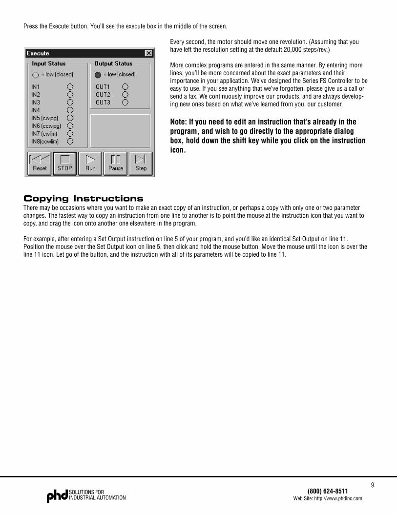
Press the Execute button. You’ll see the execute box in the middle of the screen.
Every second, the motor should move one revolution. (Assuming that youhave left the resolution setting at the default 20,000 steps/rev.)
More complex programs are entered in the same manner. By entering morelines, you’ll be more concerned about the exact parameters and theirimportance in your application. We’ve designed the Series FS Controller to beeasy to use. If you see anything that we’ve forgotten, please give us a call orsend a fax. We continuously improve our products, and are always develop-ing new ones based on what we’ve learned from you, our customer.
Note: If you need to edit an instruction that’s already in theprogram, and wish to go directly to the appropriate dialogbox, hold down the shift key while you click on the instructionicon.
Copying InstructionsThere may be occasions where you want to make an exact copy of an instruction, or perhaps a copy with only one or two parameterchanges. The fastest way to copy an instruction from one line to another is to point the mouse at the instruction icon that you want tocopy, and drag the icon onto another one elsewhere in the program.
For example, after entering a Set Output instruction on line 5 of your program, and you’d like an identical Set Output on line 11.Position the mouse over the Set Output icon on line 5, then click and hold the mouse button. Move the mouse until the icon is over theline 11 icon. Let go of the button, and the instruction with all of its parameters will be copied to line 11.
10SOLUTIONS FORINDUSTRIAL AUTOMATION
(800) 624-8511Web Site: http://www.phdinc.com
Inserting and Deleting Program Steps
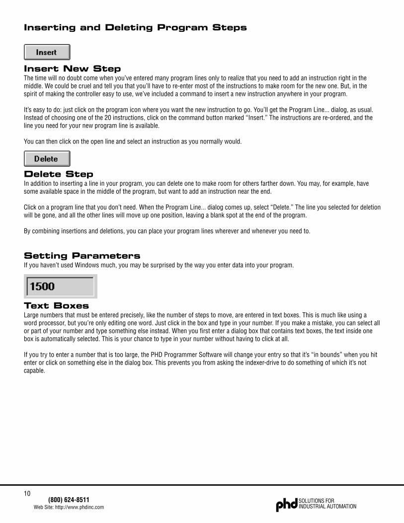
Insert New StepThe time will no doubt come when you’ve entered many program lines only to realize that you need to add an instruction right in themiddle. We could be cruel and tell you that you’ll have to re-enter most of the instructions to make room for the new one. But, in thespirit of making the controller easy to use, we’ve included a command to insert a new instruction anywhere in your program.
It’s easy to do: just click on the program icon where you want the new instruction to go. You’ll get the Program Line... dialog, as usual.Instead of choosing one of the 20 instructions, click on the command button marked “Insert.” The instructions are re-ordered, and theline you need for your new program line is available.
You can then click on the open line and select an instruction as you normally would.
Delete StepIn addition to inserting a line in your program, you can delete one to make room for others farther down. You may, for example, havesome available space in the middle of the program, but want to add an instruction near the end.
Click on a program line that you don’t need. When the Program Line... dialog comes up, select “Delete.” The line you selected for deletionwill be gone, and all the other lines will move up one position, leaving a blank spot at the end of the program.
By combining insertions and deletions, you can place your program lines wherever and whenever you need to.
Setting ParametersIf you haven’t used Windows much, you may be surprised by the way you enter data into your program.
Text BoxesLarge numbers that must be entered precisely, like the number of steps to move, are entered in text boxes. This is much like using aword processor, but you’re only editing one word. Just click in the box and type in your number. If you make a mistake, you can select allor part of your number and type something else instead. When you first enter a dialog box that contains text boxes, the text inside onebox is automatically selected. This is your chance to type in your number without having to click at all.
If you try to enter a number that is too large, the PHD Programmer Software will change your entry so that it’s “in bounds” when you hitenter or click on something else in the dialog box. This prevents you from asking the indexer-drive to do something of which it’s notcapable.
11(800) 624-8511
Web Site: http://www.phdinc.comSOLUTIONS FORINDUSTRIAL AUTOMATION
Scroll Bars
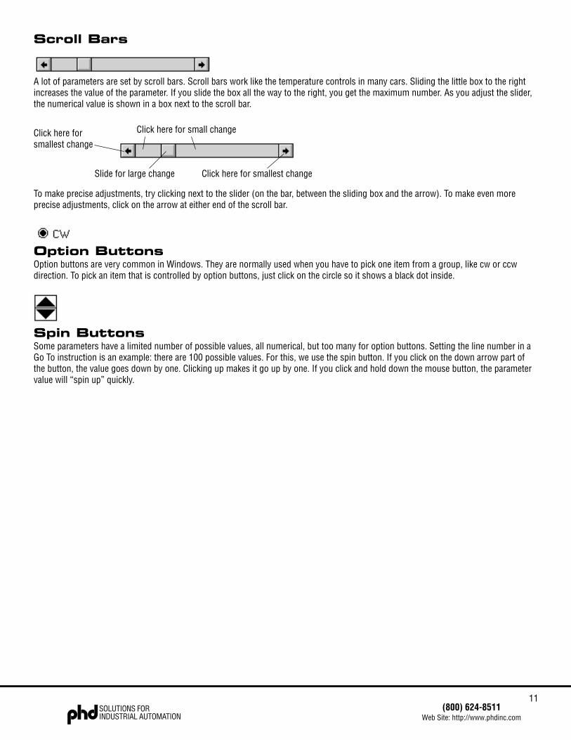
A lot of parameters are set by scroll bars. Scroll bars work like the temperature controls in many cars. Sliding the little box to the rightincreases the value of the parameter. If you slide the box all the way to the right, you get the maximum number. As you adjust the slider,the numerical value is shown in a box next to the scroll bar.
To make precise adjustments, try clicking next to the slider (on the bar, between the sliding box and the arrow). To make even moreprecise adjustments, click on the arrow at either end of the scroll bar.
Option ButtonsOption buttons are very common in Windows. They are normally used when you have to pick one item from a group, like cw or ccwdirection. To pick an item that is controlled by option buttons, just click on the circle so it shows a black dot inside.
Spin ButtonsSome parameters have a limited number of possible values, all numerical, but too many for option buttons. Setting the line number in aGo To instruction is an example: there are 100 possible values. For this, we use the spin button. If you click on the down arrow part ofthe button, the value goes down by one. Clicking up makes it go up by one. If you click and hold down the mouse button, the parametervalue will “spin up” quickly.
Click here for small change
Slide for large change Click here for smallest change
Click here forsmallest change
12SOLUTIONS FORINDUSTRIAL AUTOMATION
(800) 624-8511Web Site: http://www.phdinc.com
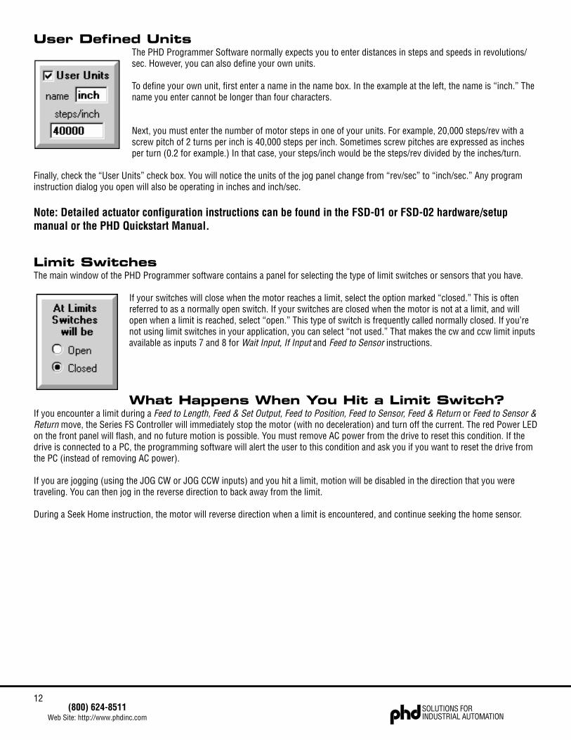
User Defined UnitsThe PHD Programmer Software normally expects you to enter distances in steps and speeds in revolutions/sec. However, you can also define your own units.
To define your own unit, first enter a name in the name box. In the example at the left, the name is “inch.” Thename you enter cannot be longer than four characters.
Next, you must enter the number of motor steps in one of your units. For example, 20,000 steps/rev with ascrew pitch of 2 turns per inch is 40,000 steps per inch. Sometimes screw pitches are expressed as inchesper turn (0.2 for example.) In that case, your steps/inch would be the steps/rev divided by the inches/turn.
Finally, check the “User Units” check box. You will notice the units of the jog panel change from “rev/sec” to “inch/sec.” Any programinstruction dialog you open will also be operating in inches and inch/sec.
Note: Detailed actuator configuration instructions can be found in the FSD-01 or FSD-02 hardware/setupmanual or the PHD Quickstart Manual.
Limit SwitchesThe main window of the PHD Programmer software contains a panel for selecting the type of limit switches or sensors that you have.
If your switches will close when the motor reaches a limit, select the option marked “closed.” This is oftenreferred to as a normally open switch. If your switches are closed when the motor is not at a limit, and willopen when a limit is reached, select “open.” This type of switch is frequently called normally closed. If you’renot using limit switches in your application, you can select “not used.” That makes the cw and ccw limit inputsavailable as inputs 7 and 8 for Wait Input, If Input and Feed to Sensor instructions.
What Happens When You Hit a Limit Switch?If you encounter a limit during a Feed to Length, Feed & Set Output, Feed to Position, Feed to Sensor, Feed & Return or Feed to Sensor &Return move, the Series FS Controller will immediately stop the motor (with no deceleration) and turn off the current. The red Power LEDon the front panel will flash, and no future motion is possible. You must remove AC power from the drive to reset this condition. If thedrive is connected to a PC, the programming software will alert the user to this condition and ask you if you want to reset the drive fromthe PC (instead of removing AC power).
If you are jogging (using the JOG CW or JOG CCW inputs) and you hit a limit, motion will be disabled in the direction that you weretraveling. You can then jog in the reverse direction to back away from the limit.
During a Seek Home instruction, the motor will reverse direction when a limit is encountered, and continue seeking the home sensor.

13(800) 624-8511
Web Site: http://www.phdinc.comSOLUTIONS FORINDUSTRIAL AUTOMATION
Front Panel STOP ButtonThe PHD FSC-01 Motion Controller has a red button on the front panel marked “STOP.” This button can be used to interrupt motion atany time. After pressing the STOP button, the motor will stop and the front panel Power LED will then flash until the AC power isremoved. If the FSC-01 is connected to a PC running the PHD Programmer, the software will alert the user on screen to the condition,and ask if you want to reset the motion controller from the PC.
Setting the Motor CurrentNote: Current setting only applies to PHD indexers with built-in drives, like the FSD-01 and FSD-02. TheFSC-01 does not have an internal motor driver, so the current setting has no effect on the FSC-01.
The drive current must be set to match the motor. First, determine the rated current for themotor. For specific motor current information, please consult the appropriate FSD-01 orFSD-02 hardware/setup manual. You can operate a motor at less than the rated current. Itwill have less torque than it would at the rated current, but will run cooler and make lessaudible noise.
In the PHD Programmer software, the current is controlled in the main window by thepanel on the upper left side of the screen. To adjust the current setting, just slide the scrollbar left or right. Precise adjustments can be made by clicking on the arrows at each end ofthe scroll bar.
Note: Detailed motor current settings can be found in the FSD-01 orFSD-02 hardware/setup manual.
Idle Current ReductionYour drive is equipped with a feature that automatically reduces the motor current anytime the motor is not moving. This reduces motorand drive heating. For example, setting the idle current to 50% reduces drive heating by about 50% and lowers motor heating by 75%.This feature can be set at any of four levels: 0%, 25%, 50%, and 100%. The 100% setting is useful when a high holding torque isrequired, as the drive does not reduce the current at all. The 0% setting is for applications in which no holding torque is required.
To minimize motor and drive heating we highly recommend that you use the idle current reduction feature unless your application strictlyforbids it. The idle current setting is chosen using the option buttons in the motor current panel.
14SOLUTIONS FORINDUSTRIAL AUTOMATION
(800) 624-8511Web Site: http://www.phdinc.com
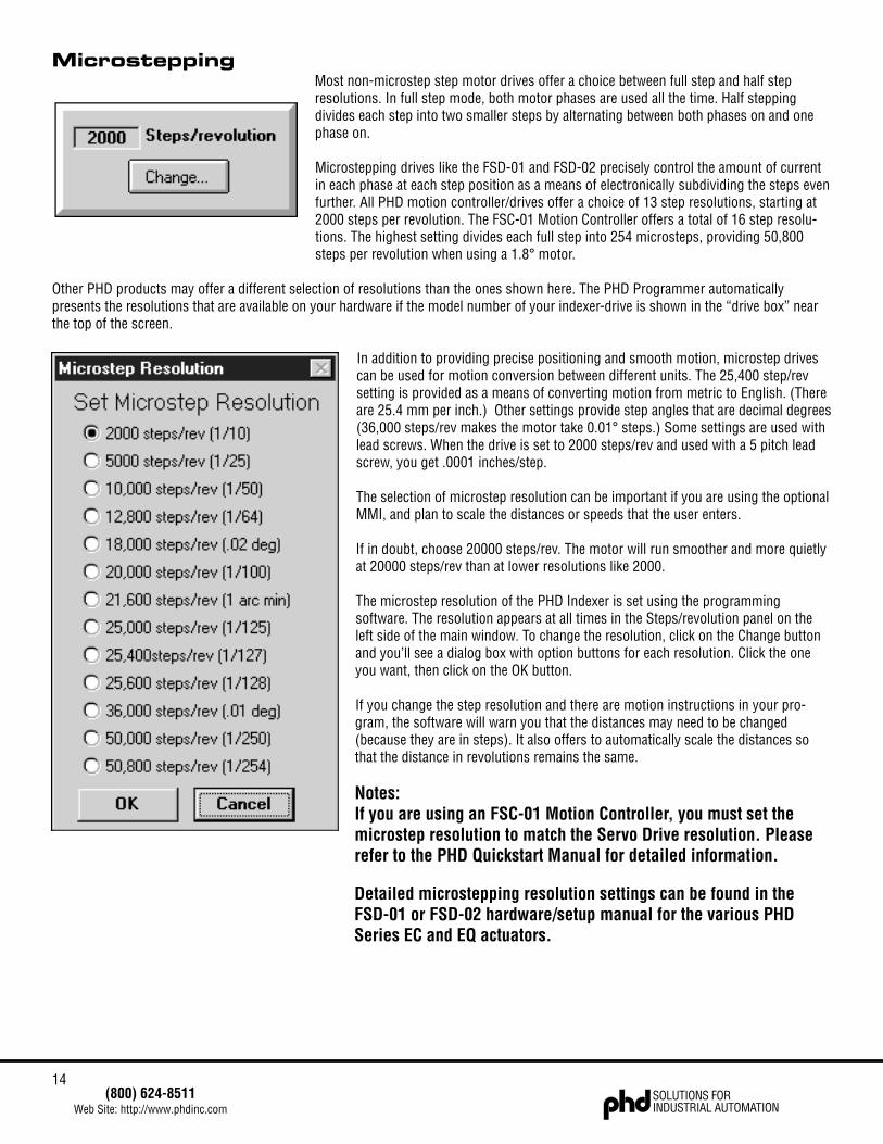
MicrosteppingMost non-microstep step motor drives offer a choice between full step and half stepresolutions. In full step mode, both motor phases are used all the time. Half steppingdivides each step into two smaller steps by alternating between both phases on and onephase on.
Microstepping drives like the FSD-01 and FSD-02 precisely control the amount of currentin each phase at each step position as a means of electronically subdividing the steps evenfurther. All PHD motion controller/drives offer a choice of 13 step resolutions, starting at2000 steps per revolution. The FSC-01 Motion Controller offers a total of 16 step resolu-tions. The highest setting divides each full step into 254 microsteps, providing 50,800steps per revolution when using a 1.8° motor.
Other PHD products may offer a different selection of resolutions than the ones shown here. The PHD Programmer automaticallypresents the resolutions that are available on your hardware if the model number of your indexer-drive is shown in the “drive box” nearthe top of the screen.
In addition to providing precise positioning and smooth motion, microstep drivescan be used for motion conversion between different units. The 25,400 step/revsetting is provided as a means of converting motion from metric to English. (Thereare 25.4 mm per inch.) Other settings provide step angles that are decimal degrees(36,000 steps/rev makes the motor take 0.01° steps.) Some settings are used withlead screws. When the drive is set to 2000 steps/rev and used with a 5 pitch leadscrew, you get .0001 inches/step.
The selection of microstep resolution can be important if you are using the optionalMMI, and plan to scale the distances or speeds that the user enters.
If in doubt, choose 20000 steps/rev. The motor will run smoother and more quietlyat 20000 steps/rev than at lower resolutions like 2000.
The microstep resolution of the PHD Indexer is set using the programmingsoftware. The resolution appears at all times in the Steps/revolution panel on theleft side of the main window. To change the resolution, click on the Change buttonand you’ll see a dialog box with option buttons for each resolution. Click the oneyou want, then click on the OK button.
If you change the step resolution and there are motion instructions in your pro-gram, the software will warn you that the distances may need to be changed(because they are in steps). It also offers to automatically scale the distances sothat the distance in revolutions remains the same.
Notes:If you are using an FSC-01 Motion Controller, you must set themicrostep resolution to match the Servo Drive resolution. Pleaserefer to the PHD Quickstart Manual for detailed information.
Detailed microstepping resolution settings can be found in theFSD-01 or FSD-02 hardware/setup manual for the various PHDSeries EC and EQ actuators.
15(800) 624-8511
Web Site: http://www.phdinc.comSOLUTIONS FORINDUSTRIAL AUTOMATION
JoggingTwo of the Series FS Controller input terminals are provided for jogging the motor.
If the controller is connected to a PC with the programming software running, the jog inputs will function under two conditions:
• if the program is not executing• if the program is executing a Wait Input command.
If the controller is operating in stand alone mode (i.e. without a computer attached) then the jog inputs work when the program isexecuting the Wait Input instruction.
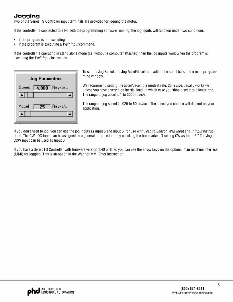
To set the Jog Speed and Jog Accel/decel rate, adjust the scroll bars in the main program-ming window.
We recommend setting the accel/decel to a modest rate. 25 rev/s/s usually works wellunless you have a very high inertial load, in which case you should set it to a lower rate.The range of jog accel is 1 to 3000 rev/s/s.
The range of jog speed is .025 to 50 rev/sec. The speed you choose will depend on yourapplication.
If you don’t need to jog, you can use the jog inputs as input 5 and input 6, for use with Feed to Sensor, Wait Input and If Input instruc-tions. The CW JOG input can be assigned as a general purpose input by checking the box marked “Use Jog CW as Input 5.” The JogCCW input can be used as Input 6.
If you have a Series FS Controller with firmware version 1.40 or later, you can use the arrow keys on the optional man machine interface(MMI) for jogging. This is an option in the Wait for MMI Enter instruction.
16SOLUTIONS FORINDUSTRIAL AUTOMATION
(800) 624-8511Web Site: http://www.phdinc.com
Using the Optional MMI (part #64725)The Series FS Controller is available with an optional MMI (Man Machine Interface), sometimes called an operator panel. The MMIattaches to the same RS232 port that you use to connect to your PC, using the same cable. The MMI has a four line liquid crystaldisplay (LCD) and 20 keys for entering data. There are seven things you can do with the MMI:
1) You can display a message on the LCD. You might want to identify your machine (“ABC Bottle Filling Co. Model 20”) or display astatus message (“Machine Running - Status OK”).
2) You can pause your program until the user presses ENTER. For example, if you were applying preprinted labels, eventually you’llwant to halt the process until the operator loads a new roll of labels.
3) The MMI can ask the user to make a decision. For example, you might want to offer the user an option, like changing set up param-eters, that can be responded to by pressing the yes or no keys.
4) The user can be asked to enter a move distance. If you want to build a machine that feeds out material and then cuts it off, theoperator can specify how long the resulting material will be.
5) The user can be asked for a move speed. This option allows the operator to adjust a feed rate, flow rate, or other motor speedrelated setting.
6) The user can be asked for a repeat count. You can let the user set the number of parts that are processed. You can also combine arepeat loop with a Wait Time instruction to adjust dwell time.
7) You can display a menu, wait for the user to press a numeral key, then branch to a corresponding program line. Any or all of thekeys 1 - 8 can be used, each with its own branch address.
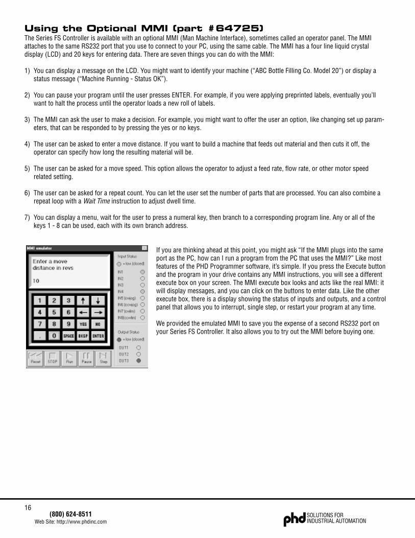
If you are thinking ahead at this point, you might ask “If the MMI plugs into the sameport as the PC, how can I run a program from the PC that uses the MMI?” Like mostfeatures of the PHD Programmer software, it’s simple. If you press the Execute buttonand the program in your drive contains any MMI instructions, you will see a differentexecute box on your screen. The MMI execute box looks and acts like the real MMI: itwill display messages, and you can click on the buttons to enter data. Like the otherexecute box, there is a display showing the status of inputs and outputs, and a controlpanel that allows you to interrupt, single step, or restart your program at any time.
We provided the emulated MMI to save you the expense of a second RS232 port onyour Series FS Controller. It also allows you to try out the MMI before buying one.
17(800) 624-8511
Web Site: http://www.phdinc.comSOLUTIONS FORINDUSTRIAL AUTOMATION
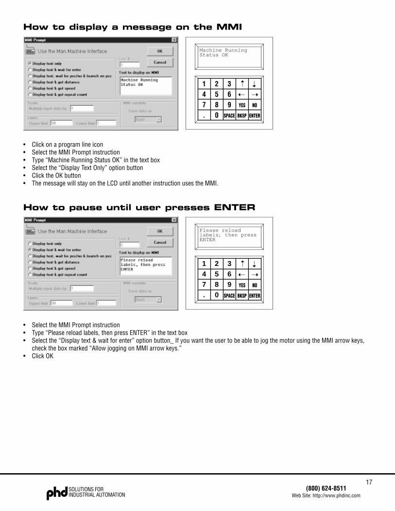
How to display a message on the MMI
• Click on a program line icon• Select the MMI Prompt instruction• Type “Machine Running Status OK” in the text box• Select the “Display Text Only” option button• Click the OK button• The message will stay on the LCD until another instruction uses the MMI.
How to pause until user presses ENTER
• Select the MMI Prompt instruction• Type “Please reload labels, then press ENTER” in the text box• Select the “Display text & wait for enter” option button_ If you want the user to be able to jog the motor using the MMI arrow keys,
check the box marked “Allow jogging on MMI arrow keys.”• Click OK
1 2 3 ➝
➝
4 5 6 ➝ ➝
7 8 9 YES NO
. 0 SPACE BKSP ENTER
Machine RunningStatus OK
1 2 3 ➝
➝
4 5 6 ➝ ➝
7 8 9 YES NO
. 0 SPACE BKSP ENTER
Please reloadlabels, then pressENTER
18SOLUTIONS FORINDUSTRIAL AUTOMATION
(800) 624-8511Web Site: http://www.phdinc.com
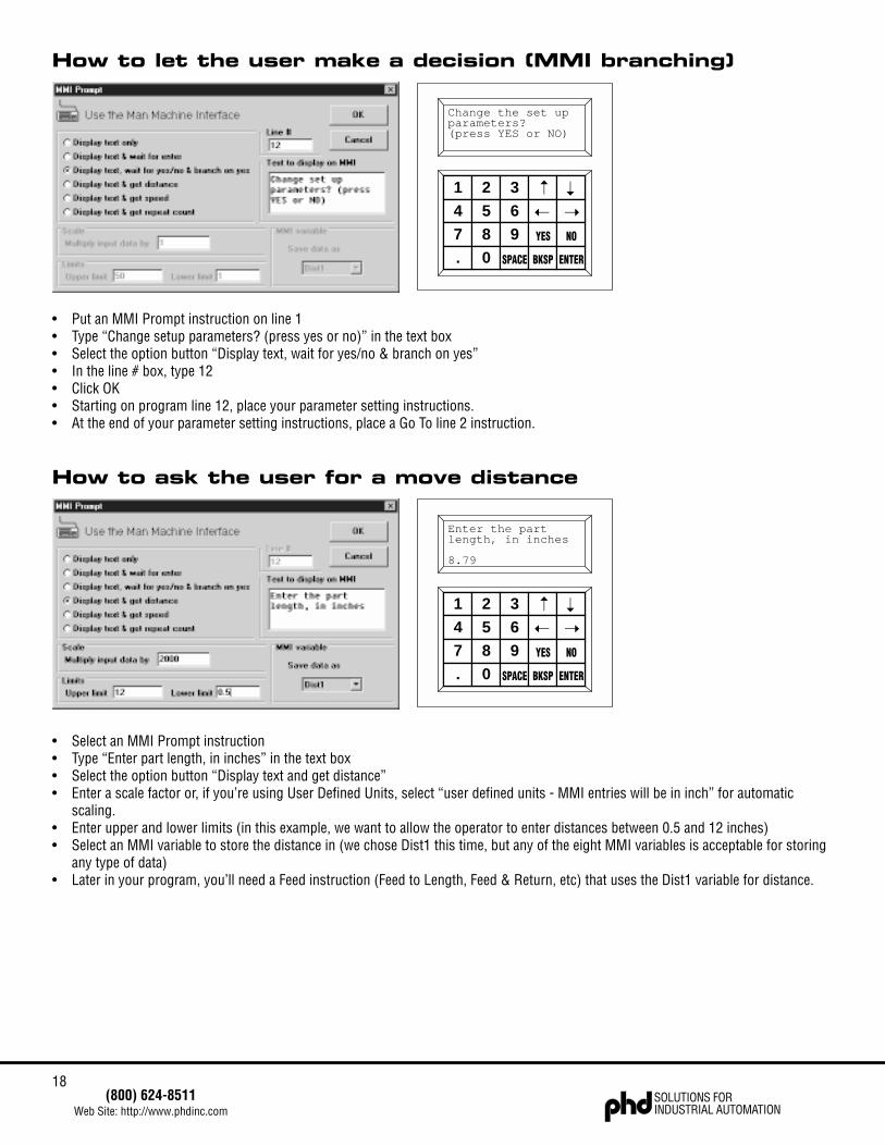
How to let the user make a decision (MMI branching)
• Put an MMI Prompt instruction on line 1• Type “Change setup parameters? (press yes or no)” in the text box• Select the option button “Display text, wait for yes/no & branch on yes”• In the line # box, type 12• Click OK• Starting on program line 12, place your parameter setting instructions.• At the end of your parameter setting instructions, place a Go To line 2 instruction.
How to ask the user for a move distance
• Select an MMI Prompt instruction• Type “Enter part length, in inches” in the text box• Select the option button “Display text and get distance”• Enter a scale factor or, if you’re using User Defined Units, select “user defined units - MMI entries will be in inch” for automatic
scaling.• Enter upper and lower limits (in this example, we want to allow the operator to enter distances between 0.5 and 12 inches)• Select an MMI variable to store the distance in (we chose Dist1 this time, but any of the eight MMI variables is acceptable for storing
any type of data)• Later in your program, you’ll need a Feed instruction (Feed to Length, Feed & Return, etc) that uses the Dist1 variable for distance.
1 2 3 ➝
➝
4 5 6 ➝ ➝
7 8 9 YES NO
. 0 SPACE BKSP ENTER
Change the set upparameters?(press YES or NO)
1 2 3 ➝
➝
4 5 6 ➝ ➝
7 8 9 YES NO
. 0 SPACE BKSP ENTER
Enter the partlength, in inches
8.79
19(800) 624-8511
Web Site: http://www.phdinc.comSOLUTIONS FORINDUSTRIAL AUTOMATION
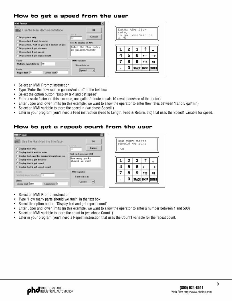
How to get a speed from the user
• Select an MMI Prompt instruction• Type “Enter the flow rate, in gallons/minute” in the text box• Select the option button “Display text and get speed”• Enter a scale factor (in this example, one gallon/minute equals 10 revolutions/sec of the motor)• Enter upper and lower limits (in this example, we want to allow the operator to enter flow rates between 1 and 5 gal/min)• Select an MMI variable to store the speed in (we chose Speed1)• Later in your program, you’ll need a Feed instruction (Feed to Length, Feed & Return, etc) that uses the Speed1 variable for speed.
How to get a repeat count from the user
• Select an MMI Prompt instruction• Type “How many parts should we run?” in the text box• Select the option button “Display text and get repeat count”• Enter upper and lower limits (in this example, we want to allow the operator to enter a number between 1 and 500)• Select an MMI variable to store the count in (we chose Count1)• Later in your program, you’ll need a Repeat instruction that uses the Count1 variable for the repeat count.
1 2 3 ➝
➝
4 5 6 ➝ ➝
7 8 9 YES NO
. 0 SPACE BKSP ENTER
Enter the flowrate,in gallons/minute2.75
1 2 3 ➝
➝
4 5 6 ➝ ➝
7 8 9 YES NO
. 0 SPACE BKSP ENTER
How many partsshould we run?
150
20SOLUTIONS FORINDUSTRIAL AUTOMATION
(800) 624-8511Web Site: http://www.phdinc.com
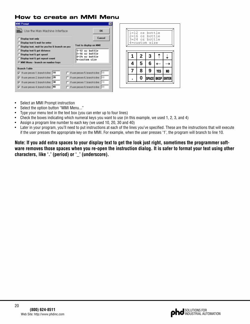
How to create an MMI Menu
• Select an MMI Prompt instruction• Select the option button “MMI Menu...”• Type your menu text in the text box (you can enter up to four lines)• Check the boxes indicating which numeral keys you want to use (in this example, we used 1, 2, 3, and 4)• Assign a program line number to each key (we used 10, 20, 30 and 40)• Later in your program, you’ll need to put instructions at each of the lines you’ve specified. These are the instructions that will execute
if the user presses the appropriate key on the MMI. For example, when the user presses ‘1’, the program will branch to line 10.
Note: If you add extra spaces to your display text to get the look just right, sometimes the programmer soft-ware removes those spaces when you re-open the instruction dialog. It is safer to format your text using othercharacters, like ‘.’ (period) or ‘_’ (underscore).
1 2 3 ➝
➝
4 5 6 ➝ ➝
7 8 9 YES NO
. 0 SPACE BKSP ENTER
1=12 oz bottle2=16 oz bottle3=24 oz bottle4=custom size
21(800) 624-8511
Web Site: http://www.phdinc.comSOLUTIONS FORINDUSTRIAL AUTOMATION
Making Your Move
MMI PromptThe MMI Prompt instruction is used with the optional MMI (Man Machine Interface). MMI prompts allow your program to displaymessages on the MMI screen, and can gather data from the operator to be used by other instructions. The MMI can also pause theprogram until the user presses the ENTER button. It can allow the user to make a decision, then press the YES or NO button. If the userpresses YES, the program branches to another program line. If the user presses NO, the program goes to the next line.
If you just want to display a message, such as “Machine Running - Status OK”, put an MMI Prompt instruction in your program at thepoint where you want the message to appear. Check the option button marked “Display Text Only” and type in your message. Once theMMI Prompt instruction has been executed, the message will stay on the screen until changed by another instruction that uses the MMIdisplay.
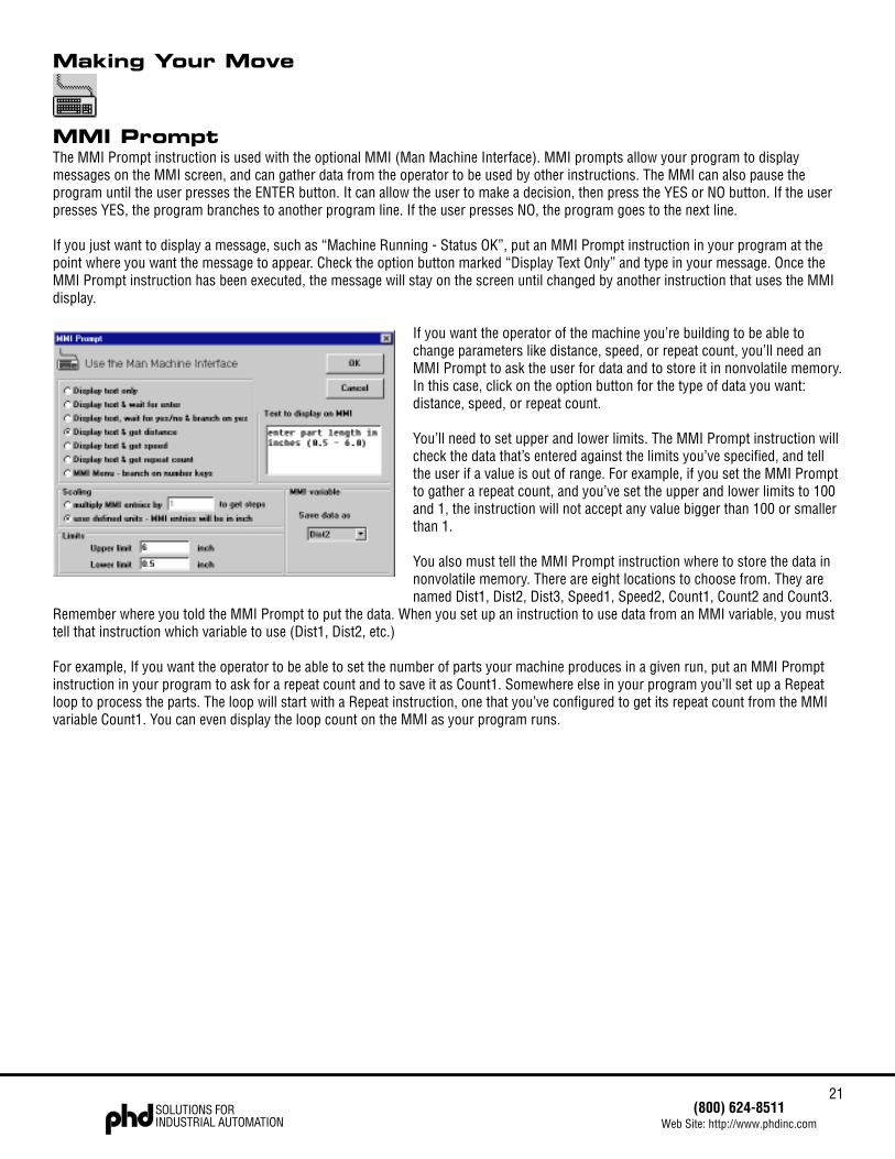
If you want the operator of the machine you’re building to be able tochange parameters like distance, speed, or repeat count, you’ll need anMMI Prompt to ask the user for data and to store it in nonvolatile memory.In this case, click on the option button for the type of data you want:distance, speed, or repeat count.
You’ll need to set upper and lower limits. The MMI Prompt instruction willcheck the data that’s entered against the limits you’ve specified, and tellthe user if a value is out of range. For example, if you set the MMI Promptto gather a repeat count, and you’ve set the upper and lower limits to 100and 1, the instruction will not accept any value bigger than 100 or smallerthan 1.
You also must tell the MMI Prompt instruction where to store the data innonvolatile memory. There are eight locations to choose from. They arenamed Dist1, Dist2, Dist3, Speed1, Speed2, Count1, Count2 and Count3.
Remember where you told the MMI Prompt to put the data. When you set up an instruction to use data from an MMI variable, you musttell that instruction which variable to use (Dist1, Dist2, etc.)
For example, If you want the operator to be able to set the number of parts your machine produces in a given run, put an MMI Promptinstruction in your program to ask for a repeat count and to save it as Count1. Somewhere else in your program you’ll set up a Repeatloop to process the parts. The loop will start with a Repeat instruction, one that you’ve configured to get its repeat count from the MMIvariable Count1. You can even display the loop count on the MMI as your program runs.

22SOLUTIONS FORINDUSTRIAL AUTOMATION
(800) 624-8511Web Site: http://www.phdinc.com
ScalingThe Series FS Controllers work internally in steps and revolutions per second. The MMI Prompt can accept data from the user in otherunits (like inches or inches/sec) and automatically scale the data to internal units. There are two ways to do that.
The easiest method of scaling is to set up user units on the main screen. That way your entire program can be entered in your units. Seepage 14 for an explanation of user defined units.
Another way to scale user entries is to enter a scale factor directly into the MMI Prompt dialog box. That way you can use different scalefactors in different MMI Prompts.
Scaling is only available when gathering distance or speed data.
Other Uses of MMI PromptsIf you want to pause your program until the user presses the ENTER key on the MMI, choose the option marked “Display text & wait forenter.” If you wish, you can allow the operator to use the MMI arrow keys for jogging.
To allow the user to make a decision, select “Display text, wait for yes/no & branch on yes.” Be sure to enter a line number in the Line #box. The program will jump to that line if the user presses YES. If the user presses NO, the program will execute the next line after theMMI Prompt.
The MMI Menu option lets you assign line numbers to as many as eight numeral keys, and display text on all four lines of the MMI.When the operator presses one of the numeral keys, the program branches to the corresponding line. This is an easy way to set up amenu driven system.
To see more examples of MMI Prompts, turn to page 19.
23(800) 624-8511
Web Site: http://www.phdinc.comSOLUTIONS FORINDUSTRIAL AUTOMATION
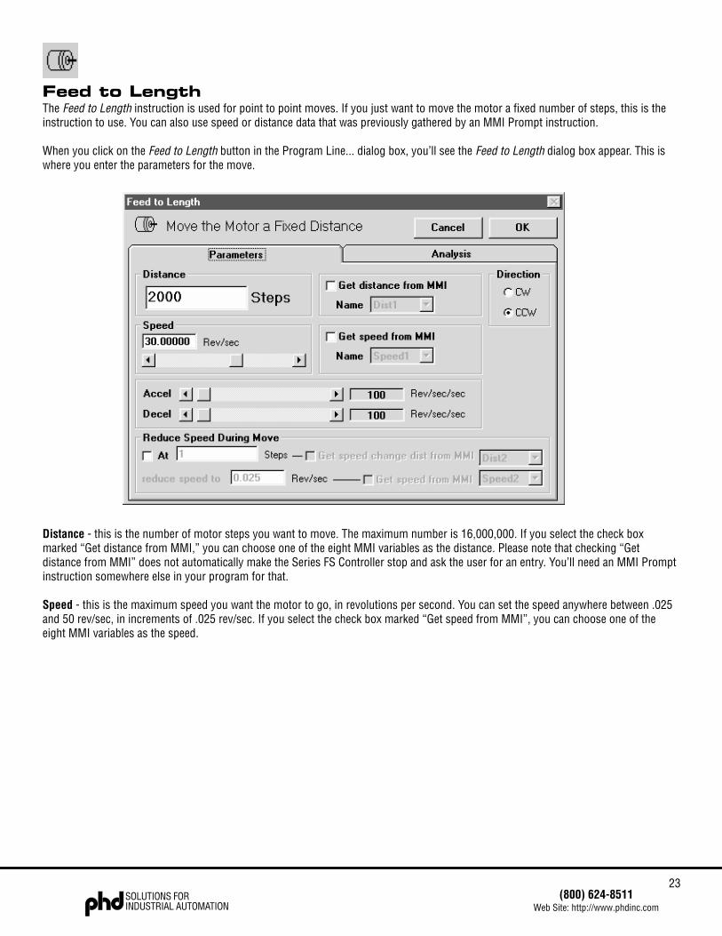
Feed to LengthThe Feed to Length instruction is used for point to point moves. If you just want to move the motor a fixed number of steps, this is theinstruction to use. You can also use speed or distance data that was previously gathered by an MMI Prompt instruction.
When you click on the Feed to Length button in the Program Line... dialog box, you’ll see the Feed to Length dialog box appear. This iswhere you enter the parameters for the move.
Distance - this is the number of motor steps you want to move. The maximum number is 16,000,000. If you select the check boxmarked “Get distance from MMI,” you can choose one of the eight MMI variables as the distance. Please note that checking “Getdistance from MMI” does not automatically make the Series FS Controller stop and ask the user for an entry. You’ll need an MMI Promptinstruction somewhere else in your program for that.
Speed - this is the maximum speed you want the motor to go, in revolutions per second. You can set the speed anywhere between .025and 50 rev/sec, in increments of .025 rev/sec. If you select the check box marked “Get speed from MMI”, you can choose one of theeight MMI variables as the speed.
24SOLUTIONS FORINDUSTRIAL AUTOMATION
(800) 624-8511Web Site: http://www.phdinc.com
You can also reduce speed during the move by checking the box marked “Reduce speed during move.” This is useful for applicationswhere a tool may need to approach a work piece quickly, but slow down just before making contact.
Accel - step motors cannot achieve a high speed instantly. The indexer-drive must gradually accelerate the motor to speed. The rate atwhich you can accelerate depends on the inertia of the motor and load, the torque available from the motor, and how fast you want it togo. You may need to experiment to find this out. The Series FS Controller has an acceleration range of 1 to 3000 revs/sec/sec.
Decel - this is the rate at which the drive decelerates to a stop at the end of the move. It’s also the rate at which the motor reduces speedif you choose that option. The range is the same as for acceleration. Because friction encourages a motor to stop, you can usually setdecel higher than accel.
Direction - you can choose cw or ccw as the direction for the move. Just dot the appropriate circle by clicking on it.
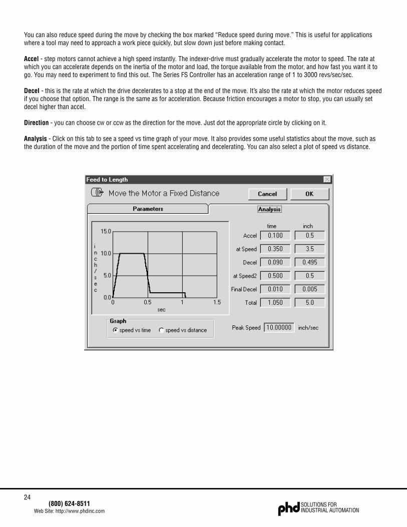
Analysis - Click on this tab to see a speed vs time graph of your move. It also provides some useful statistics about the move, such asthe duration of the move and the portion of time spent accelerating and decelerating. You can also select a plot of speed vs distance.
25(800) 624-8511
Web Site: http://www.phdinc.comSOLUTIONS FORINDUSTRIAL AUTOMATION
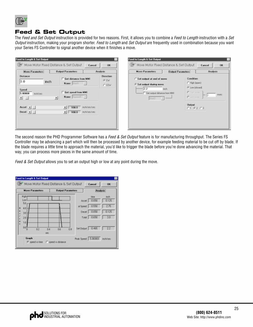
Feed & Set OutputThe Feed and Set Output instruction is provided for two reasons. First, it allows you to combine a Feed to Length instruction with a SetOutput instruction, making your program shorter. Feed to Length and Set Output are frequently used in combination because you wantyour Series FS Controller to signal another device when it finishes a move.
The second reason the PHD Programmer Software has a Feed & Set Output feature is for manufacturing throughput. The Series FSController may be advancing a part which will then be processed by another device, for example feeding material to be cut off by blade. Ifthe blade requires a little time to approach the material, you’d like to trigger the blade before you’re done advancing the material. Thatway, you can process more pieces in the same amount of time.
Feed & Set Output allows you to set an output high or low at any point during the move.

26SOLUTIONS FORINDUSTRIAL AUTOMATION
(800) 624-8511Web Site: http://www.phdinc.com
Feed & ReturnThe Feed & Return instruction is used for point to point moves where you want to return to the starting point.For example, if the motor was driving a cut-off knife, you would want to retract the knife after cutting.
Feed & Return requires many of the same parameters as Feed to Length: distance, speed, accel, decel and direction. For explanations ofthese, please refer to the Feed to Length section of the manual.
You’ll also need to set the return speed. The range is .025 to 50 revolutions per second. In the case of the cut-off knife, you might wantto feed slowly, as the knife is cutting, then retract quickly. Thus, you would set the return speed higher than the forward speed.
Return delay determines how long the Series FS Controller waits between the end of the feed move and the start of the return. Thiscould, for example, give the machine time to remove a part before retracting. Since a motor and load need time to “settle out” aftermoving, you should not set return speed to less than 0.2 seconds unless you are certain that your motor and load settle more quicklythan normal.
27(800) 624-8511
Web Site: http://www.phdinc.comSOLUTIONS FORINDUSTRIAL AUTOMATION
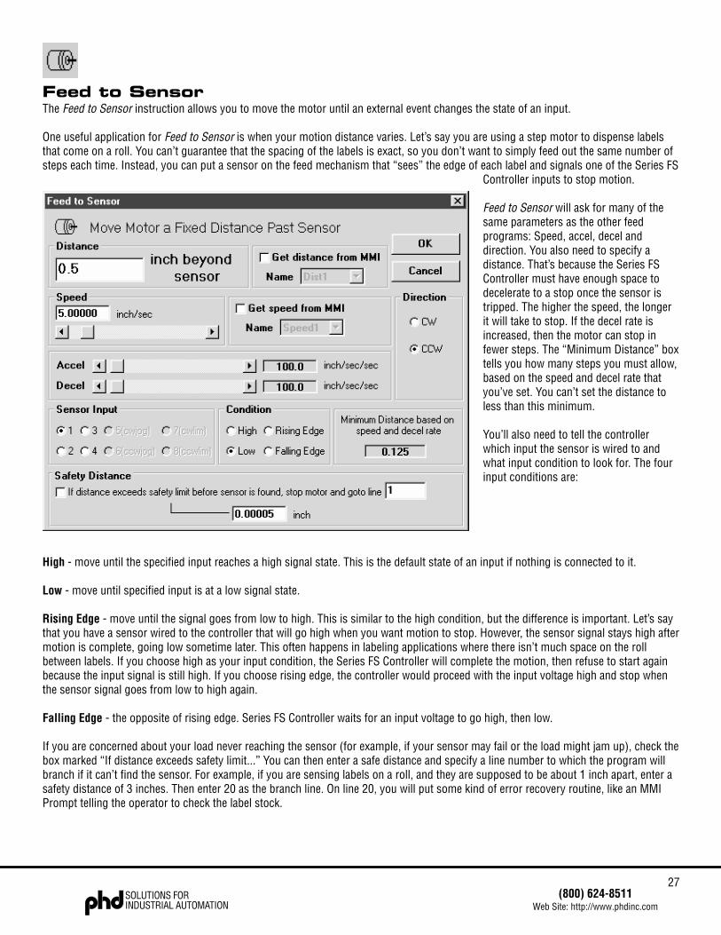
Feed to SensorThe Feed to Sensor instruction allows you to move the motor until an external event changes the state of an input.
One useful application for Feed to Sensor is when your motion distance varies. Let’s say you are using a step motor to dispense labelsthat come on a roll. You can’t guarantee that the spacing of the labels is exact, so you don’t want to simply feed out the same number ofsteps each time. Instead, you can put a sensor on the feed mechanism that “sees” the edge of each label and signals one of the Series FS
Controller inputs to stop motion.
Feed to Sensor will ask for many of thesame parameters as the other feedprograms: Speed, accel, decel anddirection. You also need to specify adistance. That’s because the Series FSController must have enough space todecelerate to a stop once the sensor istripped. The higher the speed, the longerit will take to stop. If the decel rate isincreased, then the motor can stop infewer steps. The “Minimum Distance” boxtells you how many steps you must allow,based on the speed and decel rate thatyou’ve set. You can’t set the distance toless than this minimum.
You’ll also need to tell the controllerwhich input the sensor is wired to andwhat input condition to look for. The fourinput conditions are:
High - move until the specified input reaches a high signal state. This is the default state of an input if nothing is connected to it.
Low - move until specified input is at a low signal state.
Rising Edge - move until the signal goes from low to high. This is similar to the high condition, but the difference is important. Let’s saythat you have a sensor wired to the controller that will go high when you want motion to stop. However, the sensor signal stays high aftermotion is complete, going low sometime later. This often happens in labeling applications where there isn’t much space on the rollbetween labels. If you choose high as your input condition, the Series FS Controller will complete the motion, then refuse to start againbecause the input signal is still high. If you choose rising edge, the controller would proceed with the input voltage high and stop whenthe sensor signal goes from low to high again.
Falling Edge - the opposite of rising edge. Series FS Controller waits for an input voltage to go high, then low.
If you are concerned about your load never reaching the sensor (for example, if your sensor may fail or the load might jam up), check thebox marked “If distance exceeds safety limit...” You can then enter a safe distance and specify a line number to which the program willbranch if it can’t find the sensor. For example, if you are sensing labels on a roll, and they are supposed to be about 1 inch apart, enter asafety distance of 3 inches. Then enter 20 as the branch line. On line 20, you will put some kind of error recovery routine, like an MMIPrompt telling the operator to check the label stock.
28SOLUTIONS FORINDUSTRIAL AUTOMATION
(800) 624-8511Web Site: http://www.phdinc.com
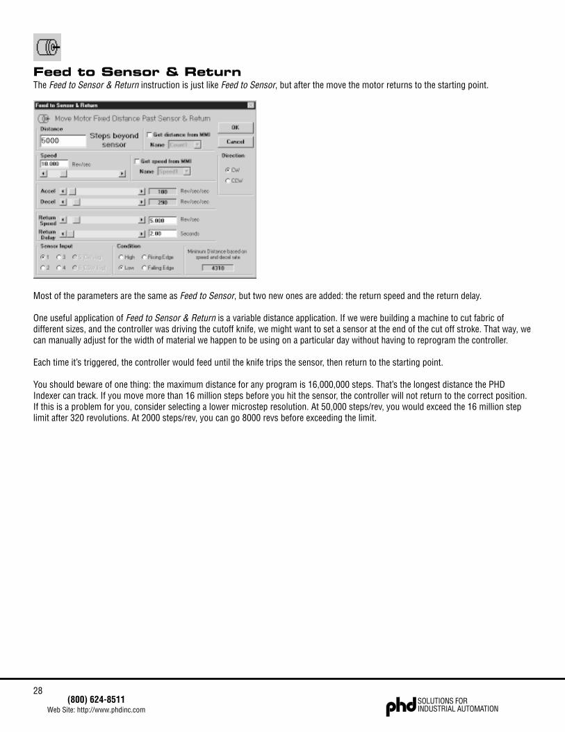
Feed to Sensor & ReturnThe Feed to Sensor & Return instruction is just like Feed to Sensor, but after the move the motor returns to the starting point.
Most of the parameters are the same as Feed to Sensor, but two new ones are added: the return speed and the return delay.
One useful application of Feed to Sensor & Return is a variable distance application. If we were building a machine to cut fabric ofdifferent sizes, and the controller was driving the cutoff knife, we might want to set a sensor at the end of the cut off stroke. That way, wecan manually adjust for the width of material we happen to be using on a particular day without having to reprogram the controller.
Each time it’s triggered, the controller would feed until the knife trips the sensor, then return to the starting point.
You should beware of one thing: the maximum distance for any program is 16,000,000 steps. That’s the longest distance the PHDIndexer can track. If you move more than 16 million steps before you hit the sensor, the controller will not return to the correct position.If this is a problem for you, consider selecting a lower microstep resolution. At 50,000 steps/rev, you would exceed the 16 million steplimit after 320 revolutions. At 2000 steps/rev, you can go 8000 revs before exceeding the limit.
29(800) 624-8511
Web Site: http://www.phdinc.comSOLUTIONS FORINDUSTRIAL AUTOMATION
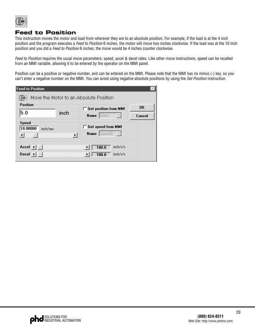
Feed to PositionThis instruction moves the motor and load from wherever they are to an absolute position. For example, if the load is at the 4 inchposition and the program executes a Feed to Position 6 inches, the motor will move two inches clockwise. If the load was at the 10 inchposition and you did a Feed to Position 6 inches, the move would be 4 inches counter clockwise.
Feed to Position requires the usual move parameters: speed, accel & decel rates. Like other move instructions, speed can be recalledfrom an MMI variable, allowing it to be entered by the operator on the MMI panel.
Position can be a positive or negative number, and can be entered on the MMI. Please note that the MMI has no minus (-) key, so youcan’t enter a negative number on the MMI. You can avoid using negative absolute positions by using the Set Position instruction.
30SOLUTIONS FORINDUSTRIAL AUTOMATION
(800) 624-8511Web Site: http://www.phdinc.com
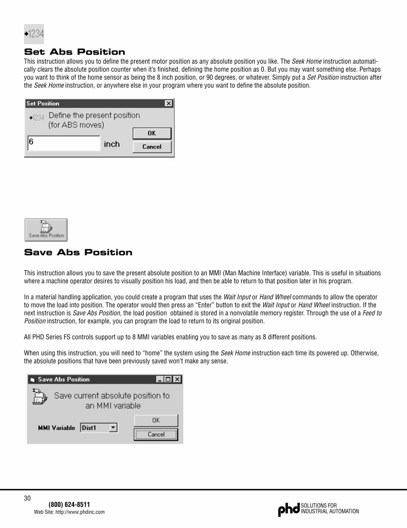
Set Abs PositionThis instruction allows you to define the present motor position as any absolute position you like. The Seek Home instruction automati-cally clears the absolute position counter when it’s finished, defining the home position as 0. But you may want something else. Perhapsyou want to think of the home sensor as being the 8 inch position, or 90 degrees, or whatever. Simply put a Set Position instruction afterthe Seek Home instruction, or anywhere else in your program where you want to define the absolute position.
Save Abs Position
This instruction allows you to save the present absolute position to an MMI (Man Machine Interface) variable. This is useful in situationswhere a machine operator desires to visually position his load, and then be able to return to that position later in his program.
In a material handling application, you could create a program that uses the Wait Input or Hand Wheel commands to allow the operatorto move the load into position. The operator would then press an “Enter” button to exit the Wait Input or Hand Wheel instruction. If thenext instruction is Save Abs Position, the load position obtained is stored in a nonvolatile memory register. Through the use of a Feed toPosition instruction, for example, you can program the load to return to its original position.
All PHD Series FS controls support up to 8 MMI variables enabling you to save as many as 8 different positions.
When using this instruction, you will need to “home” the system using the Seek Home instruction each time its powered up. Otherwise,the absolute positions that have been previously saved won’t make any sense.
31(800) 624-8511
Web Site: http://www.phdinc.comSOLUTIONS FORINDUSTRIAL AUTOMATION
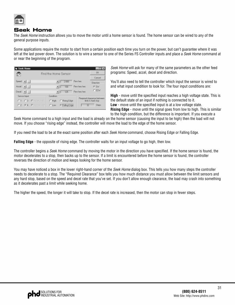
Seek HomeThe Seek Home instruction allows you to move the motor until a home sensor is found. The home sensor can be wired to any of thegeneral purpose inputs.
Some applications require the motor to start from a certain position each time you turn on the power, but can’t guarantee where it wasleft at the last power down. The solution is to wire a sensor to one of the Series FS Controller inputs and place a Seek Home command ator near the beginning of the program.
Seek Home will ask for many of the same parameters as the other feedprograms: Speed, accel, decel and direction.
You’ll also need to tell the controller which input the sensor is wired toand what input condition to look for. The four input conditions are:
High - move until the specified input reaches a high voltage state. This isthe default state of an input if nothing is connected to it.Low - move until the specified input is at a low voltage state.Rising Edge - move until the signal goes from low to high. This is similarto the high condition, but the difference is important. If you execute a
Seek Home command to a high input and the load is already on the home sensor (causing the input to be high) then the load will notmove. If you choose “rising edge” instead, the controller will move the load to the edge of the home sensor.
If you need the load to be at the exact same position after each Seek Home command, choose Rising Edge or Falling Edge.
Falling Edge - the opposite of rising edge. The controller waits for an input voltage to go high, then low.
The controller begins a Seek Home command by moving the motor in the direction you have specified. If the home sensor is found, themotor decelerates to a stop, then backs up to the sensor. If a limit is encountered before the home sensor is found, the controllerreverses the direction of motion and keeps looking for the home sensor.
You may have noticed a box in the lower right-hand corner of the Seek Home dialog box. This tells you how many steps the controllerneeds to decelerate to a stop. The “Required Clearance” box tells you how much distance you must allow between the limit sensors andany hard stop, based on the speed and decel rate that you’ve set. If you don’t allow enough clearance, the load may crash into somethingas it decelerates past a limit while seeking home.
The higher the speed, the longer it will take to stop. If the decel rate is increased, then the motor can stop in fewer steps.
32SOLUTIONS FORINDUSTRIAL AUTOMATION
(800) 624-8511Web Site: http://www.phdinc.com
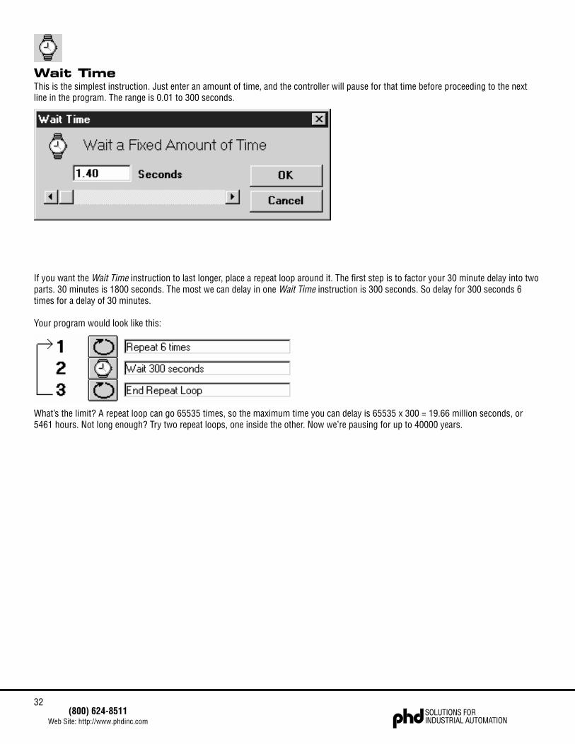
Wait TimeThis is the simplest instruction. Just enter an amount of time, and the controller will pause for that time before proceeding to the nextline in the program. The range is 0.01 to 300 seconds.
If you want the Wait Time instruction to last longer, place a repeat loop around it. The first step is to factor your 30 minute delay into twoparts. 30 minutes is 1800 seconds. The most we can delay in one Wait Time instruction is 300 seconds. So delay for 300 seconds 6times for a delay of 30 minutes.
Your program would look like this:
What’s the limit? A repeat loop can go 65535 times, so the maximum time you can delay is 65535 x 300 = 19.66 million seconds, or5461 hours. Not long enough? Try two repeat loops, one inside the other. Now we’re pausing for up to 40000 years.
33(800) 624-8511
Web Site: http://www.phdinc.comSOLUTIONS FORINDUSTRIAL AUTOMATION
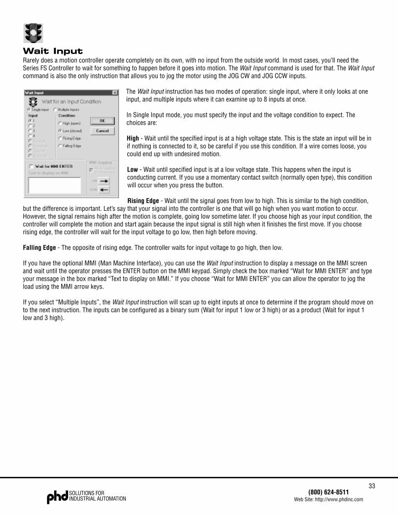
Wait InputRarely does a motion controller operate completely on its own, with no input from the outside world. In most cases, you’ll need theSeries FS Controller to wait for something to happen before it goes into motion. The Wait Input command is used for that. The Wait Inputcommand is also the only instruction that allows you to jog the motor using the JOG CW and JOG CCW inputs.
The Wait Input instruction has two modes of operation: single input, where it only looks at oneinput, and multiple inputs where it can examine up to 8 inputs at once.
In Single Input mode, you must specify the input and the voltage condition to expect. Thechoices are:
High - Wait until the specified input is at a high voltage state. This is the state an input will be inif nothing is connected to it, so be careful if you use this condition. If a wire comes loose, youcould end up with undesired motion.
Low - Wait until specified input is at a low voltage state. This happens when the input isconducting current. If you use a momentary contact switch (normally open type), this conditionwill occur when you press the button.
Rising Edge - Wait until the signal goes from low to high. This is similar to the high condition,but the difference is important. Let’s say that your signal into the controller is one that will go high when you want motion to occur.However, the signal remains high after the motion is complete, going low sometime later. If you choose high as your input condition, thecontroller will complete the motion and start again because the input signal is still high when it finishes the first move. If you chooserising edge, the controller will wait for the input voltage to go low, then high before moving.
Falling Edge - The opposite of rising edge. The controller waits for input voltage to go high, then low.
If you have the optional MMI (Man Machine Interface), you can use the Wait Input instruction to display a message on the MMI screenand wait until the operator presses the ENTER button on the MMI keypad. Simply check the box marked “Wait for MMI ENTER” and typeyour message in the box marked “Text to display on MMI.” If you choose “Wait for MMI ENTER” you can allow the operator to jog theload using the MMI arrow keys.
If you select “Multiple Inputs”, the Wait Input instruction will scan up to eight inputs at once to determine if the program should move onto the next instruction. The inputs can be configured as a binary sum (Wait for input 1 low or 3 high) or as a product (Wait for input 1low and 3 high).
34SOLUTIONS FORINDUSTRIAL AUTOMATION
(800) 624-8511Web Site: http://www.phdinc.com
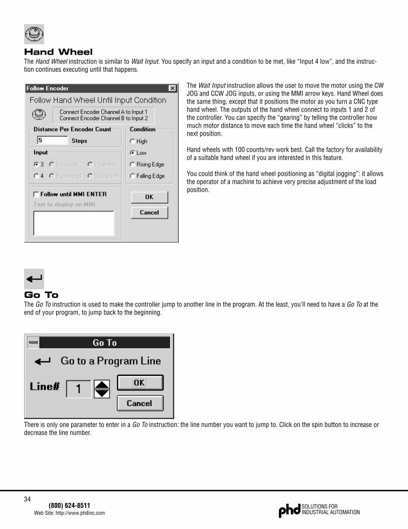
Hand WheelThe Hand Wheel instruction is similar to Wait Input. You specify an input and a condition to be met, like “Input 4 low”, and the instruc-tion continues executing until that happens.
The Wait Input instruction allows the user to move the motor using the CWJOG and CCW JOG inputs, or using the MMI arrow keys. Hand Wheel doesthe same thing, except that it positions the motor as you turn a CNC typehand wheel. The outputs of the hand wheel connect to inputs 1 and 2 ofthe controller. You can specify the “gearing” by telling the controller howmuch motor distance to move each time the hand wheel “clicks” to thenext position.
Hand wheels with 100 counts/rev work best. Call the factory for availabilityof a suitable hand wheel if you are interested in this feature.
You could think of the hand wheel positioning as “digital jogging”: it allowsthe operator of a machine to achieve very precise adjustment of the loadposition.
Go ToThe Go To instruction is used to make the controller jump to another line in the program. At the least, you’ll need to have a Go To at theend of your program, to jump back to the beginning.
There is only one parameter to enter in a Go To instruction: the line number you want to jump to. Click on the spin button to increase ordecrease the line number.
35(800) 624-8511
Web Site: http://www.phdinc.comSOLUTIONS FORINDUSTRIAL AUTOMATION
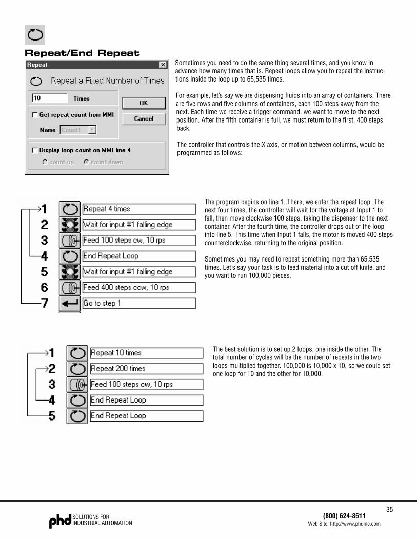
Repeat/End RepeatSometimes you need to do the same thing several times, and you know inadvance how many times that is. Repeat loops allow you to repeat the instruc-tions inside the loop up to 65,535 times.
For example, let’s say we are dispensing fluids into an array of containers. Thereare five rows and five columns of containers, each 100 steps away from thenext. Each time we receive a trigger command, we want to move to the nextposition. After the fifth container is full, we must return to the first, 400 stepsback.
The controller that controls the X axis, or motion between columns, would beprogrammed as follows:
The program begins on line 1. There, we enter the repeat loop. Thenext four times, the controller will wait for the voltage at Input 1 tofall, then move clockwise 100 steps, taking the dispenser to the nextcontainer. After the fourth time, the controller drops out of the loopinto line 5. This time when Input 1 falls, the motor is moved 400 stepscounterclockwise, returning to the original position.
Sometimes you may need to repeat something more than 65,535times. Let’s say your task is to feed material into a cut off knife, andyou want to run 100,000 pieces.
The best solution is to set up 2 loops, one inside the other. Thetotal number of cycles will be the number of repeats in the twoloops multiplied together. 100,000 is 10,000 x 10, so we could setone loop for 10 and the other for 10,000.
36SOLUTIONS FORINDUSTRIAL AUTOMATION
(800) 624-8511Web Site: http://www.phdinc.com
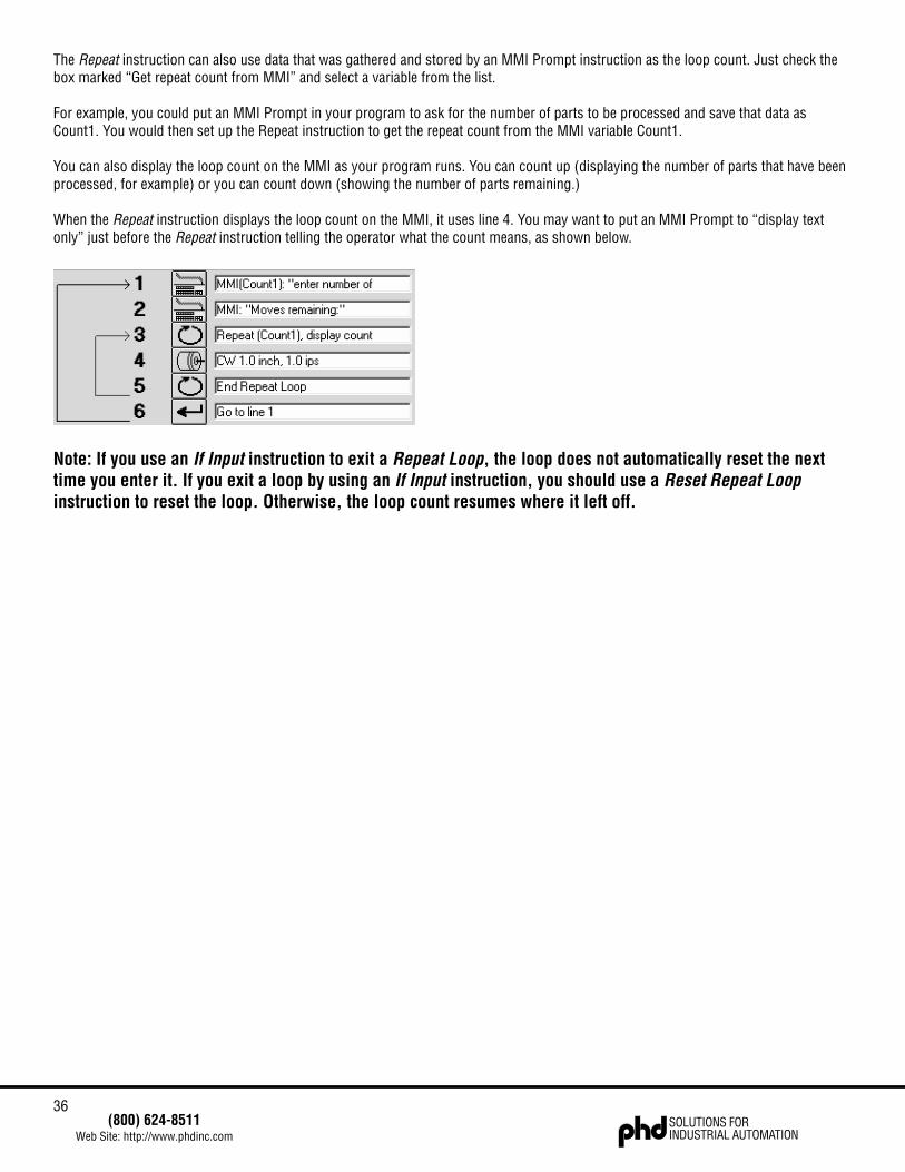
The Repeat instruction can also use data that was gathered and stored by an MMI Prompt instruction as the loop count. Just check thebox marked “Get repeat count from MMI” and select a variable from the list.
For example, you could put an MMI Prompt in your program to ask for the number of parts to be processed and save that data asCount1. You would then set up the Repeat instruction to get the repeat count from the MMI variable Count1.
You can also display the loop count on the MMI as your program runs. You can count up (displaying the number of parts that have beenprocessed, for example) or you can count down (showing the number of parts remaining.)
When the Repeat instruction displays the loop count on the MMI, it uses line 4. You may want to put an MMI Prompt to “display textonly” just before the Repeat instruction telling the operator what the count means, as shown below.
Note: If you use an If Input instruction to exit a Repeat Loop, the loop does not automatically reset the nexttime you enter it. If you exit a loop by using an If Input instruction, you should use a Reset Repeat Loopinstruction to reset the loop. Otherwise, the loop count resumes where it left off.
37(800) 624-8511
Web Site: http://www.phdinc.comSOLUTIONS FORINDUSTRIAL AUTOMATION
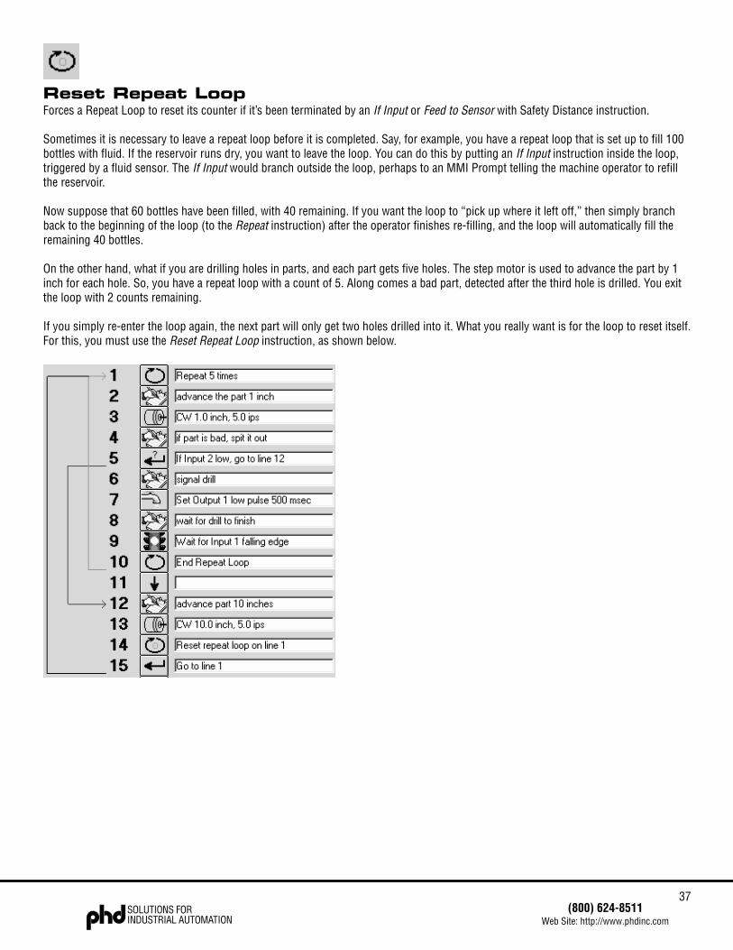
Reset Repeat LoopForces a Repeat Loop to reset its counter if it’s been terminated by an If Input or Feed to Sensor with Safety Distance instruction.
Sometimes it is necessary to leave a repeat loop before it is completed. Say, for example, you have a repeat loop that is set up to fill 100bottles with fluid. If the reservoir runs dry, you want to leave the loop. You can do this by putting an If Input instruction inside the loop,triggered by a fluid sensor. The If Input would branch outside the loop, perhaps to an MMI Prompt telling the machine operator to refillthe reservoir.
Now suppose that 60 bottles have been filled, with 40 remaining. If you want the loop to “pick up where it left off,” then simply branchback to the beginning of the loop (to the Repeat instruction) after the operator finishes re-filling, and the loop will automatically fill theremaining 40 bottles.
On the other hand, what if you are drilling holes in parts, and each part gets five holes. The step motor is used to advance the part by 1inch for each hole. So, you have a repeat loop with a count of 5. Along comes a bad part, detected after the third hole is drilled. You exitthe loop with 2 counts remaining.
If you simply re-enter the loop again, the next part will only get two holes drilled into it. What you really want is for the loop to reset itself.For this, you must use the Reset Repeat Loop instruction, as shown below.
38SOLUTIONS FORINDUSTRIAL AUTOMATION
(800) 624-8511Web Site: http://www.phdinc.com
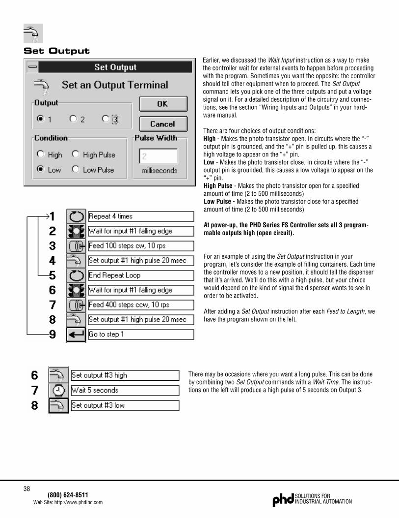
Set OutputEarlier, we discussed the Wait Input instruction as a way to makethe controller wait for external events to happen before proceedingwith the program. Sometimes you want the opposite: the controllershould tell other equipment when to proceed. The Set Outputcommand lets you pick one of the three outputs and put a voltagesignal on it. For a detailed description of the circuitry and connec-tions, see the section “Wiring Inputs and Outputs” in your hard-ware manual.
There are four choices of output conditions:High - Makes the photo transistor open. In circuits where the “-”output pin is grounded, and the “+” pin is pulled up, this causes ahigh voltage to appear on the “+” pin.Low - Makes the photo transistor close. In circuits where the “-”output pin is grounded, this causes a low voltage to appear on the“+” pin.High Pulse - Makes the photo transistor open for a specifiedamount of time (2 to 500 milliseconds)Low Pulse - Makes the photo transistor close for a specifiedamount of time (2 to 500 milliseconds)
At power-up, the PHD Series FS Controller sets all 3 program-mable outputs high (open circuit).
For an example of using the Set Output instruction in yourprogram, let’s consider the example of filling containers. Each timethe controller moves to a new position, it should tell the dispenserthat it’s arrived. We’ll do this with a high pulse, but your choicewould depend on the kind of signal the dispenser wants to see inorder to be activated.
After adding a Set Output instruction after each Feed to Length, wehave the program shown on the left.
There may be occasions where you want a long pulse. This can be doneby combining two Set Output commands with a Wait Time. The instruc-tions on the left will produce a high pulse of 5 seconds on Output 3.
39(800) 624-8511
Web Site: http://www.phdinc.comSOLUTIONS FORINDUSTRIAL AUTOMATION
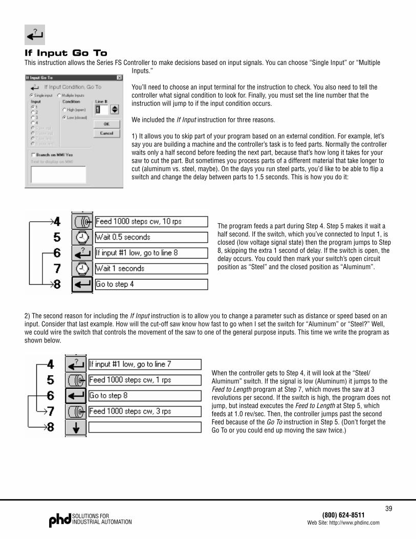
If Input Go ToThis instruction allows the Series FS Controller to make decisions based on input signals. You can choose “Single Input” or “Multiple
Inputs.”
You’ll need to choose an input terminal for the instruction to check. You also need to tell thecontroller what signal condition to look for. Finally, you must set the line number that theinstruction will jump to if the input condition occurs.
We included the If Input instruction for three reasons.
1) It allows you to skip part of your program based on an external condition. For example, let’ssay you are building a machine and the controller’s task is to feed parts. Normally the controllerwaits only a half second before feeding the next part, because that’s how long it takes for yoursaw to cut the part. But sometimes you process parts of a different material that take longer tocut (aluminum vs. steel, maybe). On the days you run steel parts, you’d like to be able to flip aswitch and change the delay between parts to 1.5 seconds. This is how you do it:
The program feeds a part during Step 4. Step 5 makes it wait ahalf second. If the switch, which you’ve connected to Input 1, isclosed (low voltage signal state) then the program jumps to Step8, skipping the extra 1 second of delay. If the switch is open, thedelay occurs. You could then mark your switch’s open circuitposition as “Steel” and the closed position as “Aluminum”.
2) The second reason for including the If Input instruction is to allow you to change a parameter such as distance or speed based on aninput. Consider that last example. How will the cut-off saw know how fast to go when I set the switch for “Aluminum” or “Steel?” Well,we could wire the switch that controls the movement of the saw to one of the general purpose inputs. This time we write the program asshown below.
When the controller gets to Step 4, it will look at the “Steel/Aluminum” switch. If the signal is low (Aluminum) it jumps to theFeed to Length program at Step 7, which moves the saw at 3revolutions per second. If the switch is high, the program does notjump, but instead executes the Feed to Length at Step 5, whichfeeds at 1.0 rev/sec. Then, the controller jumps past the secondFeed because of the Go To instruction in Step 5. (Don’t forget theGo To or you could end up moving the saw twice.)

40SOLUTIONS FORINDUSTRIAL AUTOMATION
(800) 624-8511Web Site: http://www.phdinc.com
3) The final reason we’ve given you the power of If Input is so you can have multiple programs within your 100 line program space.Perhaps what you want your system to do is two completely different things depending on an input. If each of these tasks requires 4instructions. This is what you do:
Depending on the state of Input 2, the program will either execute lines 4 - 9 or lines 11 - 15. Either way, the program ultimately returnsto line 3 to check the condition of the switch again.
You can also use the optional Man Machine Interface (MMI) as the decision making input of an If Input instruction. Simply check the boxmarked “Branch on MMI YES” and type in the message that you want the operator to see. If the operator presses the YES button, thedrive will jump to the line you’ve specified in the line number box. If the operator presses NO, the program moves on to the next line.
Note: If you use an If Input instruction to exit a Repeat Loop, the loop does not automatically reset the nexttime you enter it. If you exit a loop by using an If Input instruction, you should use a Reset Repeat Loopinstruction to reset the loop. Otherwise, the loop count resumes where it left off.
41(800) 624-8511
Web Site: http://www.phdinc.comSOLUTIONS FORINDUSTRIAL AUTOMATION
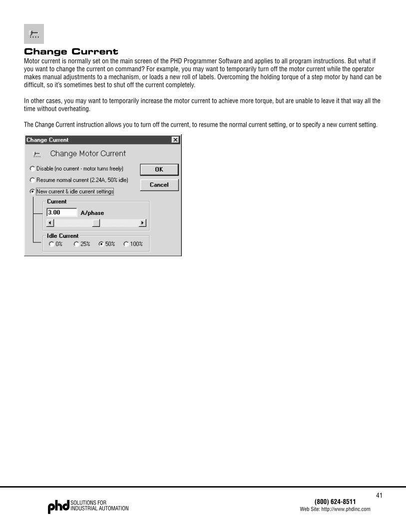
Change CurrentMotor current is normally set on the main screen of the PHD Programmer Software and applies to all program instructions. But what ifyou want to change the current on command? For example, you may want to temporarily turn off the motor current while the operatormakes manual adjustments to a mechanism, or loads a new roll of labels. Overcoming the holding torque of a step motor by hand can bedifficult, so it’s sometimes best to shut off the current completely.
In other cases, you may want to temporarily increase the motor current to achieve more torque, but are unable to leave it that way all thetime without overheating.
The Change Current instruction allows you to turn off the current, to resume the normal current setting, or to specify a new current setting.

42SOLUTIONS FORINDUSTRIAL AUTOMATION
(800) 624-8511Web Site: http://www.phdinc.com
CommentThe Comment lets you leave notes in your program. That way if someone else needs to modify your program in the future they’llunderstand what you’ve done. The comments can also help you organize the program for yourself.
Whether you save your program to disk or just download it to the drive, the comments stay with it. They do not affect the way yourprogram runs: when the controller executes a program, it skips over the comments.
We suggest that you place a comment on the first line of your program to let future programmers know who wrote the program, when itwas written, and what it does. You can also put in comments at other places in your program. Perhaps just before a Feed to Lengthmove, you would want to add the comment “Rotate the part 1/4 turn.”
A little time spent now commenting your program might save you a great deal more time later on, when you’ve forgotten that “Feed toLength 3000 Steps” means “Rotate the part 1/4 turn.”
There is a limit to the number of comments your program can have. The controller has a “string pool” of 400 characters. All MMIPrompts text goes into the string pool, as any Comment, Wait Input or If Input instructions whose strings exceed 12 characters.
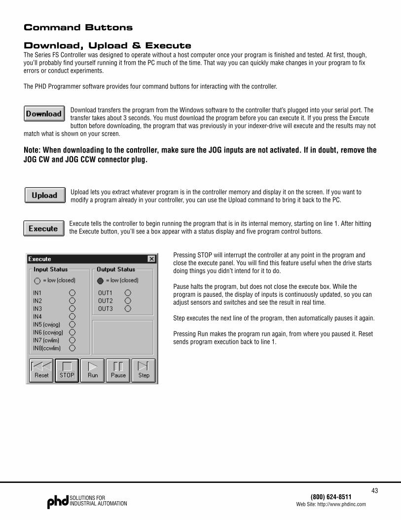
43(800) 624-8511
Web Site: http://www.phdinc.comSOLUTIONS FORINDUSTRIAL AUTOMATION
Command Buttons
Download, Upload & ExecuteThe Series FS Controller was designed to operate without a host computer once your program is finished and tested. At first, though,you’ll probably find yourself running it from the PC much of the time. That way you can quickly make changes in your program to fixerrors or conduct experiments.
The PHD Programmer software provides four command buttons for interacting with the controller.
Download transfers the program from the Windows software to the controller that’s plugged into your serial port. Thetransfer takes about 3 seconds. You must download the program before you can execute it. If you press the Executebutton before downloading, the program that was previously in your indexer-drive will execute and the results may not
match what is shown on your screen.
Note: When downloading to the controller, make sure the JOG inputs are not activated. If in doubt, remove theJOG CW and JOG CCW connector plug.
Upload lets you extract whatever program is in the controller memory and display it on the screen. If you want tomodify a program already in your controller, you can use the Upload command to bring it back to the PC.
Execute tells the controller to begin running the program that is in its internal memory, starting on line 1. After hittingthe Execute button, you’ll see a box appear with a status display and five program control buttons.
Pressing STOP will interrupt the controller at any point in the program andclose the execute panel. You will find this feature useful when the drive startsdoing things you didn’t intend for it to do.
Pause halts the program, but does not close the execute box. While theprogram is paused, the display of inputs is continuously updated, so you canadjust sensors and switches and see the result in real time.
Step executes the next line of the program, then automatically pauses it again.
Pressing Run makes the program run again, from where you paused it. Resetsends program execution back to line 1.
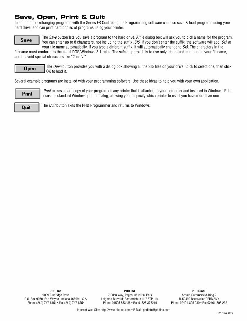
Internet Web Site: http://www.phdinc.com • E-Mail: [email protected] 2/00 4925
PHD Ltd. PHD GmbH7 Eden Way, Pages Industrial Park Arnold-Sommerfeld-Ring 2
Leighton Buzzard, Bedfordshire LU7 8TP U.K. D-52499 Baesweiler GERMANYPhone 01525 853488 • Fax 01525 378210 Phone 02401-805 230 • Fax 02401-805 232
PHD, Inc.9009 Clubridge Drive
P.O. Box 9070, Fort Wayne, Indiana 46899 U.S.A.Phone (260) 747-6151 • Fax (260) 747-6754
Save, Open, Print & QuitIn addition to exchanging programs with the Series FS Controller, the Programming software can also save & load programs using yourhard drive, and can print hard copies of programs using your printer.
The Save button lets you save a program to the hard drive. A file dialog box will ask you to pick a name for the program.You can enter up to 8 characters, not including the suffix .SI5. If you don’t enter the suffix, the software will add .SI5 toyour file name automatically. If you type a different suffix, it will automatically change to SI5. The characters in the
filename must conform to the usual DOS/Windows 3.1 rules. The safest approach is to use only letters and numbers in your filename,and to avoid special characters like “?”or “/.”
The Open button provides you with a dialog box showing all the SI5 files on your drive. Click to select one, then clickOK to load it.
Several example programs are installed with your programming software. Use these ideas to help you with your own application.
Print makes a hard copy of your program on any printer that is attached to your computer and installed in Windows. Printuses the standard Windows printer dialog, allowing you to specify which printer to use if you have more than one.
The Quit button exits the PHD Programmer and returns to Windows.
Recommended


![BCK - PHD, Inclitstore.phdinc.com/pdf.asp?filename=BCK02.pdf · Series BCK Cylinder is provided with a cushion retract. Its maximum kinetic energy rating is 60.5 in-lb [6.84 Nm]](https://img.pdfslide.net/doc/110x75/5fc171584abab747344e5618/bck-phd-series-bck-cylinder-is-provided-with-a-cushion-retract-its-maximum-kinetic.jpg)