User ManualRM-15Powered Subwoofer
This powered subwoofer leaves nothing to be desired. With over 2 years of engineering and testing, the RM-15 completes the TruAudio theater package. The RM-15 uses a black anodized aluminum woofer, driven by a, 1000 watt, powerful A/B power amplifier built exclusively for this cabinet and driver array.
The RM-15 is timbre matched to all TruAudio architectural speakers, making combining different models in an AV system, simple. Additional TruAudio speakers can be added to a system with the confidence that the speakers will remain balanced.
The Red Mountain Subwoofer is carefully packaged before shipping. Inspect the product immediately for any kind of damage. If for some reason damage has occurred, please contact your Dealer or TruAudio immediately. We recommend that you retain the packaging in case a need arises for you to transport your speaker.
The RM-15 includes: Subwoofer cabinet and grill, power cord, instruction manual, a warranty card, and (4) heavy-duty plastic feet attached to the bottom of the cabinet.
CAUTION: DO NOT OPEN THE SUBWOOFER. THIS WILL VOID THE WARRANTY.To reduce the risk of electrical shock and fire, do not remove the amplifier panel from the back of the cabinet or the subwoofer from the front of the cabinet. There are NO fuses or serviceable parts.All service to this product MUST be done by a TruAudio Authorized repair center.
Before installing, please read the following instructions: • Always turn off the power of your receiver/preamp and the powered subwoofer • When turning your amplifier/receiver on, make sure your volume is turned all the way down • Never expose the subwoofer to excessive cold, heat, humidity, or direct sunlight • This device should never be used in, on or near water due to risk of fatal shock • DO NOT attempt to open or dismantle this subwoofer • The subwoofer should always have plenty of air flow to reduce the chance of over heating
Subwoofer Placement
Th RM-15 is engineered, designed and built to reproduce low frequencies at and below 150 Hz. Frequencies at this level are omni-directional. This makes it easy to find placement for the sub; howev-er, there are also several location options that can either give more or less bass. When placed near a wall, you will get a louder, deeper bass. Placing the subwoofer in a corner will produce a high volume of bass output, while near only one wall will provide less. Placement away from any wall may not produce enough bass. Even a slight change of how the unit sits will alter the bass output. We suggest trying your subwoofer in different locations to allow you to hear the difference of bass output and decide what is best for your room and the listener’s preference.
RM-15
Unpacking and Inspection
We suggest to place the subwoofer close to the pair of speakers it will be matched with. For example, if the subwoofer is to reproduce bass from the front two channels, then it should be located near the front two speakers. If it’s to reproduce bass from the rear effect channels, then the sub should be located near the rear speakers.
NOTE: Because of the acoustics of the sub installed into an enclosed area, we also suggest using some kind of sound dampening material in the space to prevent a hollow “boomy” sound coming from the area behind the subwoofer. Each installation of this product can be different, so figure out what works best for that specific room and system. Consult with your client and find out their preference when it comes to bass output and loudness of the subwoofer.
INPUT CONNECTIONS 1. Left/Right InputsRCA style jacks that will accept standard line level inputs from a pre-amp level source. They will accept a stereo signal and internally combine it into mono. Both left and right input jacks must be connected to the source in order to drive the amplifier to full output. The use of a “Y” cord is suggested if amono source is all that is available.
2. LFE Direct InputRCA jack that will accept a signal from the mono LFE (Low Frequency Effects) output on a pre-amp or receiver that is equipped with a dedicated sub bass output. This input bypasses the amplifier’s own internal low pass filter circuitry, relying instead on the processed output provided by the sourceequipment. This would be the recommended connection for most home theatre surround sound receivers and pre-amps. We would also suggest the use of the LFE input when an external line level electronic crossover or frequency dividingnetwork is used.
3. Power InputThis unit features an IEC grounding type power input connector. The IEC inlet connector also features an integrated fuse holder that contains the AC line fuse. For 230 V input, remove the fuse holder, rotate 180 degrees, and re-install. In most230 V applications a separate power cord will be required and is not included.
CONTROLS/INDICATORS4. Low Pass, GainWill match the amplifier’s input sensitivity to the output of the pre-amp source. If the source output has a variable control, we recommend that the user spend a moment or two determining the best balance between the two controls. When abalance is found between low noise, linear level control, and sufficient level to drive the amp to the required output, the gain knob can be considered to be the “volume control” for the subwoofer system.
5. Low Pass, FrequencyThis control is used to establish the highest frequency that the subwoofer will reproduce and has a range between 30 and 200 Hz. If your main speakers have good bass capability, you could set
Controls
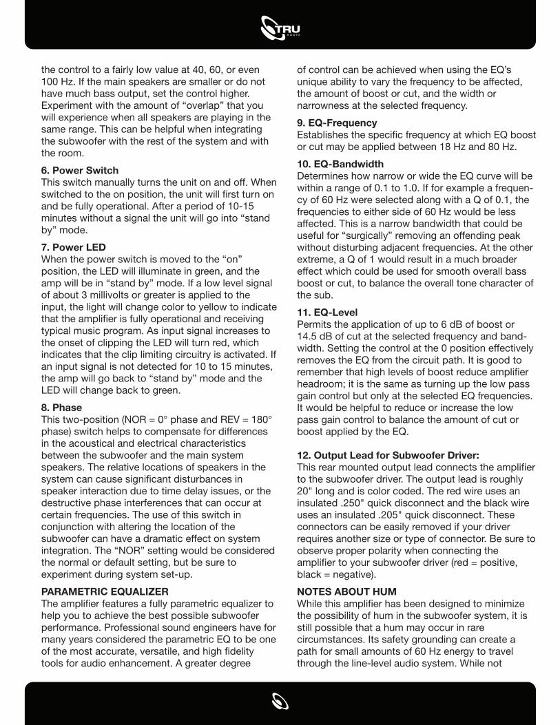
the control to a fairly low value at 40, 60, or even 100 Hz. If the main speakers are smaller or do nothave much bass output, set the control higher. Experiment with the amount of “overlap” that you will experience when all speakers are playing in the same range. This can be helpful when integrating the subwoofer with the rest of the system and with the room.
6. Power SwitchThis switch manually turns the unit on and off. When switched to the on position, the unit will �rst turn on and be fully operational. After a period of 10-15 minutes without a signal the unit will go into “stand by” mode.
7. Power LEDWhen the power switch is moved to the “on” position, the LED will illuminate in green, and the amp will be in “stand by” mode. If a low level signal of about 3 millivolts or greater is applied to the input, the light will change color to yellow to indicate that the ampli�er is fully operational and receiving typical music program. As input signal increases to the onset of clipping the LED will turn red, which indicates that the clip limiting circuitry is activated. If an input signal is not detected for 10 to 15 minutes, the amp will go back to “stand by” mode and the LED will change back to green.
8. PhaseThis two-position (NOR = 0° phase and REV = 180° phase) switch helps to compensate for differences in the acoustical and electrical characteristics between the subwoofer and the main system speakers. The relative locations of speakers in the system can cause signi�cant disturbances in speaker interaction due to time delay issues, or the destructive phase interferences that can occur at certain frequencies. The use of this switch in conjunction with altering the location of thesubwoofer can have a dramatic effect on system integration. The “NOR” setting would be considered the normal or default setting, but be sure to experiment during system set-up.
PARAMETRIC EQUALIZERThe ampli�er features a fully parametric equalizer tohelp you to achieve the best possible subwoofer performance. Professional sound engineers have for many years considered the parametric EQ to be one of the most accurate, versatile, and high �delity tools for audio enhancement. A greater degree
of control can be achieved when using the EQ’s unique ability to vary the frequency to be affected, the amount of boost or cut, and the width or narrowness at the selected frequency.
9. EQ-FrequencyEstablishes the speci�c frequency at which EQ boost or cut may be applied between 18 Hz and 80 Hz.
10. EQ-BandwidthDetermines how narrow or wide the EQ curve will be within a range of 0.1 to 1.0. If for example a frequen-cy of 60 Hz were selected along with a Q of 0.1, the frequencies to either side of 60 Hz would be less affected. This is a narrow bandwidth that could be useful for “surgically” removing an offending peakwithout disturbing adjacent frequencies. At the other extreme, a Q of 1 would result in a much broader effect which could be used for smooth overall bass boost or cut, to balance the overall tone character of the sub.
11. EQ-LevelPermits the application of up to 6 dB of boost or 14.5 dB of cut at the selected frequency and band-width. Setting the control at the 0 position effectively removes the EQ from the circuit path. It is good to remember that high levels of boost reduce ampli�er headroom; it is the same as turning up the low passgain control but only at the selected EQ frequencies. It would be helpful to reduce or increase the low pass gain control to balance the amount of cut or boost applied by the EQ.
12. Output Lead for Subwoofer Driver:This rear mounted output lead connects the ampli�er to the subwoofer driver. The output lead is roughly 20" long and is color coded. The red wire uses an insulated .250" quick disconnect and the black wire uses an insulated .205" quick disconnect. These connectors can be easily removed if your driver requires another size or type of connector. Be sure toobserve proper polarity when connecting the ampli�er to your subwoofer driver (red = positive, black = negative).
NOTES ABOUT HUMWhile this ampli�er has been designed to minimize the possibility of hum in the subwoofer system, it is still possible that a hum may occur in rare circumstances. Its safety grounding can create a path for small amounts of 60 Hz energy to travel through the line-level audio system. While not
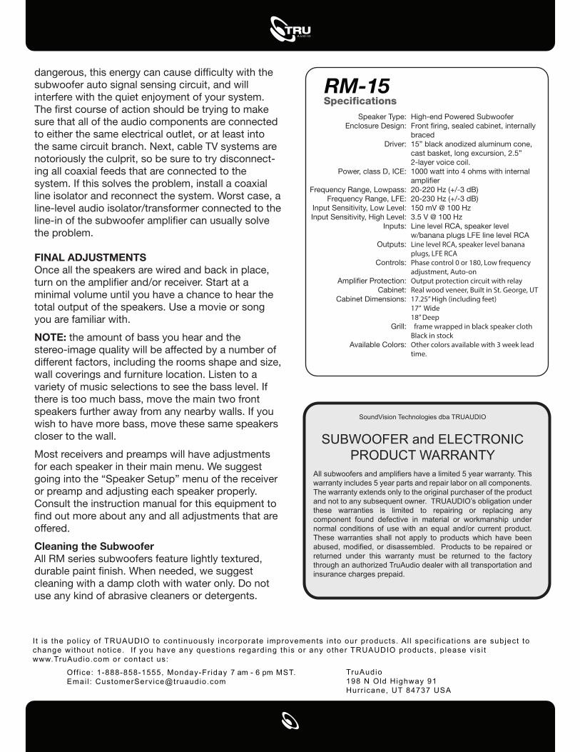
Specifications
dangerous, this energy can cause dif�culty with the subwoofer auto signal sensing circuit, and will interfere with the quiet enjoyment of your system. The �rst course of action should be trying to make sure that all of the audio components are connected to either the same electrical outlet, or at least into the same circuit branch. Next, cable TV systems are notoriously the culprit, so be sure to try disconnect-ing all coaxial feeds that are connected to the system. If this solves the problem, install a coaxial line isolator and reconnect the system. Worst case, a line-level audio isolator/transformer connected to the line-in of the subwoofer ampli�er can usually solve the problem.
FINAL ADJUSTMENTSOnce all the speakers are wired and back in place, turn on the ampli�er and/or receiver. Start at a minimal volume until you have a chance to hear the total output of the speakers. Use a movie or song you are familiar with.
NOTE: the amount of bass you hear and the stereo-image quality will be affected by a number of different factors, including the rooms shape and size, wall coverings and furniture location. Listen to a variety of music selections to see the bass level. If there is too much bass, move the main two front speakers further away from any nearby walls. If you wish to have more bass, move these same speakers closer to the wall.
Most receivers and preamps will have adjustments for each speaker in their main menu. We suggest going into the “Speaker Setup” menu of the receiver or preamp and adjusting each speaker properly. Consult the instruction manual for this equipment to �nd out more about any and all adjustments that are offered.
Cleaning the SubwooferAll RM series subwoofers feature lightly textured, durable paint �nish. When needed, we suggest cleaning with a damp cloth with water only. Do not use any kind of abrasive cleaners or detergents.
SoundVision Technologies dba TRUAUDIO
SUBWOOFER and ELECTRONIC PRODUCT WARRANTY
All subwoofers and amplifiers have a limited 5 year warranty. This warranty includes 5 year parts and repair labor on all components. The warranty extends only to the original purchaser of the product and not to any subsequent owner. TRUAUDIO’s obligation under these warranties is limited to repairing or replacing any component found defective in material or workmanship under normal conditions of use with an equal and/or current product. These warranties shall not apply to products which have been abused, modified, or disassembled. Products to be repaired or returned under this warranty must be returned to the factory through an authorized TruAudio dealer with all transportation and insurance charges prepaid.
RM-15
I t is the pol icy of TRUAUDIO to cont inuously incorporate improvements into our products. Al l speci f icat ions are subject to change without not ice. I f you have any quest ions regarding this or any other TRUAUDIO products, p lease vis i t www.TruAudio.com or contact us:
Off ice: 1-888-858-1555, Monday-Fr iday 7 am - 6 pm MST. Emai l : [email protected]
TruAudio198 N Old Highway 91Hurr icane, UT 84737 USA
Speaker Type:Enclosure Design:
Driver:
Power, class D, ICE:
Frequency Range, Lowpass:Frequency Range, LFE:
Input Sensitivity, Low Level:Input Sensitivity, High Level:
Inputs:
Outputs:
Controls:
Ampli�er Protection:Cabinet:
Cabinet Dimensions:
Grill:
Available Colors:
High-end Powered SubwooferFront �ring, sealed cabinet, internally braced15” black anodized aluminum cone, cast basket, long excursion, 2.5” 2-layer voice coil.1000 watt into 4 ohms with internal ampli�er20-220 Hz (+/-3 dB)20-230 Hz (+/-3 dB)150 mV @ 100 Hz3.5 V @ 100 HzLine level RCA, speaker level w/banana plugs LFE line level RCALine level RCA, speaker level banana plugs, LFE RCAPhase control 0 or 180, Low frequency adjustment, Auto-onOutput protection circuit with relayReal wood veneer, Built in St. George, UT17.25” High (including feet)17” Wide 18” Deep frame wrapped in black speaker clothBlack in stockOther colors available with 3 week lead time.
Recommended