j^U-a^5cQJo/J)
SACRAMENTO PLANT
PROPOSAL 1\I0„ RN-66250
SYNTHESIS OF CALCULATION METHODS FOR THE
DESIGN AND ANALYSIS OF RADIATION SHIELDS FOR
NUCLEAR ROCKET SYSTEMS
SUBMITTED TO
MARSHALL SPACE FLIGHT CENTER
VOLUME I - TECHNICAL
MARCH 1966
f» 1 R ^ T ' ^ t e ^
FILE COPY Do not remove from
R£ON Technical Information Center Aerojet-General Corporation
AEROJET-GENERAL CORPORATION S A C R A M E N T O C A L I F O R N I A
\
'Df'i Of THIS OOCi.JMFNT !S UNn^^T'-'^
TECHNICAL DOCUMENT CENTER Nuclear Rocket Operations
DOC. NO AGCS 0120-48 '' \
DISCLAIMER
This report was prepared as an account of work sponsored by an agency of the United States Government. Neither the United States Government nor any agency Thereof, nor any of their employees, makes any warranty, express or implied, or assumes any legal liability or responsibility for the accuracy, completeness, or usefulness of any information, apparatus, product, or process disclosed, or represents that its use would not infringe privately owned rights. Reference herein to any specific commercial product, process, or service by trade name, trademark, manufacturer, or otherwise does not necessarily constitute or imply its endorsement, recommendation, or favoring by the United States Government or any agency thereof. The views and opinions of authors expressed herein do not necessarily state or reflect those of the United States Government or any agency thereof.

DISCLAIMER Portions of this document may be illegible in electronic image products. Images are produced from the best available original document.
This document and the data furnished shall not be disclosed outside the Government or be reproduced, used or disclosed in whole or in part for any purpose other than to evaluate the proposal; provided, that if a contract is awarded to this offeror as a result of or in connection with the submission of such data, the Government shall have the right to reproduce, use or disclose this data to the extent provided in the contract. This restriction does not limit the Government's right to use information contained in such data if it is obtained from other sources.
CLASSIFICATION CATEGORY
UNCLASSIFIED
CLASSIFYING OFFICER DATE
AEROJET-GENERAL CORPORATION S A C R A M E N T O C A L I F O R N I A
SACRAMENTO PLANT
Gentlemen:
f — NOTICE _ _ _ ^ This report was prepared as an account of work I
t he 'unH H%?'^ " " " = " ' ' " • " Government. NeUher the United States nor the United States Enersy Research and Development Administration, nor anyTf theu employees, nor any of their contractors subcontractors, or their employees, makes any ^r ranty , express or implied, or assumes any legiQ liabihty or responsibihty for the accuracy, completene^ I c ^ s " i " 7 ° ' r ' ' " f " ™ ' - " . apparatus, p r X c " o" fZZ ^f*' "' ' ' 'P'^^^"'* <hat its use would not mfnnge pnvately owned rights.
Aerojet-General Corporation welcomes the opportunity to submit
this proposal on the Synthesis of Methods for Design Analysis on
Radiation Shields for Nuclear Rocket and Nuclear Electric Systems,
Since 195^, Aerojet has been engaged in nuclear rocket activi
ties in both Government and Company-initiated programs. Within the
past two months these efforts have culminated in the successful opera
tion and restart of the NERVA Engine Systems at full power. These
NRX/EST tests exceeded all test objectives.
Our achievements in NERVA and other major programs reflect the
capability of our personnel, facilities, management and resources which
will be applied toward accomplishment of the proposed program.
We at Aerojet approach this program with enthusiasm and with a
genuine desire for the further advancement of national prestige in the
field of nuclear rocket technology. The Corporation pledges to support
the program with all available resources to attain for the Nation still
another advance in nuclear rocketry. The pages which follow describe
how we plan to make this effort a significant step in the achievement
of that goal.
C. C. Ross
Vice President - REON
A S U B S I D I A R Y O F T H E G E N E R A L T I R E & R U B B E R C O M P A N Y
AEROJET
GENERAL
PROPOSAL NO. RN-66250
SYNTHESIS OF CALCULATION METHODS FOR THE
DESIGN AND ANALYSIS OF RADIATION SHIELDS FOR
NUCLEAR ROCKET SYSTEMS
R O C K E T E N G I N E O P E R AT I O N S - N U C L E A R
VOLUME I - TECHNICAL MARCH 1966
A E R O J E T - G E N E R A L C O R P O R A T I O N A S U B S I D I A R Y O F T H E G E N E R A L T I R E & R U B B E R C O M P A N Y
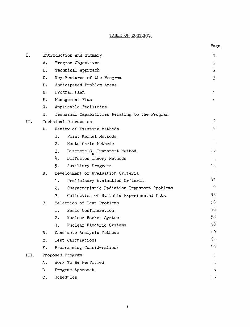
TABLE OF CONTENTS
Introduction and Summary
A. Program Objectives
B. Technical Approach
C. Key Features of the Program
D. Anticipated Problem Areas
E. Program Plan
F. Management Plan
Go Applicable Facilities
Ho Technical Capabilities Relating to the Program
Technical Discussion
A. Review of Existing Methods
1. Point Kernel Methods
2. Monte Carlo Methods
3. Discrete S Transport Method
k. Diffusion Theory Methods
5. Auxiliary Programs
B. Development of Evaluation Criteria
1. Preliminary Evaluation Criteria
2. Characteristic Radiation Transport Problems
3- Collection of Suitable Experimental Data
C. Selection of Test Problems
1. Basic Configuration
2o Nuclear Rocket System
3. Nuclear Electric Systems
Do Candidate Analysis Methods
E, Test Calculations
F. Programming Considerations
Proposed Program
A. Work To Be Performed
Bo Program Approach
C. Schedules
i
TABLE OF CONTENTS (cont.)
Page
D o Report s
Eo New Technology
IV. Management Organization and Personnel
Ao Corporate Organization
Bo Project Organization
V, Supporting Information
Ao Related Experience
Bo List of Operational Digital Computer Codes
Co Computer Facilities
Do Document Facilities
VIo List of References
85 15 87
ST
90
105
105
117
13?
133
135
TABLE LIST
A Brief List of Existing Methods
Zone Description Data for Figure 5
Boundary Equation Data for Figure 5
Tentative List of Candidate Analysis Methods
A Candidate Program System
Sxunmary of User Decisions Affecting Accuracy
Summary of Calculations to be Performed
Computer Codes for Radiation Analysis at Aerojet
Table
I
II
III
IV
V
VI
VII
VIII
FIGURE LIST
S Prediction of the NERVA Fast Neutron Environment n Relative Neutron Current Along Reactor Surface
The Discrete Angular Direction for the Cylindrical S-6
Figure
1
2
Approx imat i on
ii
FIGURE LIST (cont.)
Recipe for Estimating Size of TDC Problems
Computer Plot of XE-System in ETS-1
Flow Schematic of Radiation Analys. s for NRX/EST
Elements of Nuclear Heating in the Phoebus-2 Nozzle
SNAP-8 Interplanetary Vehicle, Extended Version
XE-Engine and Engine Test Compartment Radiation Shielding
Candidate Analysis Method
Flow Chart for the Work Program
Schedule for the Proposed Program
Management Organization
Project Organization
iii
APPENDIX
Page
I. NERVA Data A-3
A. Gamma Ray Dose Rates A-3
B. Fast Neutron Flux A-3
C. Neutron Spectra A-T
II. Monte Carlo Analysis of the General Dynamics (ASTR) A-7
Experiment on Neutron Penetration Through Hydrogen
A. Introduction ^~
B. Analysis A-IO
C. Discussion of Results A-I6
References A-19
iv
I. INTRODUCTION AND SUMMARY
This proposal is submitted by Aerojet-General Corporation to the Marshall
Space Flight Center in response to Request for Proposal No. 1-6-28-00029, dated
11 February 1966, entitled: "Synthesis of Calculation Methods for the Design and
Analysis of Radiation Shields for Nuclear Rocket Systems."
The ciirrent methods used to predict radiation distributions about nuclear
rocket and nuclesir electrical systems are actually various combinations of shielding
codes, each having inherent advantages and disadvantages. These codes evolved and
were combined as a result of the immediate and pressing contractual requirements
of past and current reactor programs without sufficient emphasis directed toward
optimization of the methods on the basis of validity, efficiency, and cost. As
a result, use of these current prediction methods has resulted in numerous analytical
difficulties.
Aerojet recognizes the innate deficiencies of these current analytical
methods and responds to the Marshall Space Flight Center's requirements for a
comparison and critical evaluation of these methods by proposing a program for
objectively screening, evaluating, and selecting prediction methods which will
ensure that future calculation of radiation levels will be made quickly and
accurately.
A. PROGRAM OBJECTIVES
The proposed program has four principal objectives. The first is to
compare and critically evaluate the applicability of existing computer programs
to radiation analyses for nuclear rocket and nuclear electric systems. The second
objective is to select one or two optimiim combinations of sinalytical methods for use
in an automated analysis system that minimizes data handling by the analyst. The
third objective is to reprogrsun the selected methods in the FORTRAN-IV language.
The fourth objective is to check out the selected methods on the Marshall Space
Flight Center computer and instruct MSEC personnel in the use of the selected
programs.
1
I, Introduction and Summary (conto)
Bo TECHNICAL APPROACH
Aerojet's approach to achieve these program objectives is to conduct
a literature and field survey in order to identify and ferret out those existing
analysis methods that are either of interest or contain desirable features o
Simultaneously, criteria will be developed on the basis of the program operational
characteristics and on considerations of the analysis requirements of nuclear rocket
Eind nuclear electric systems in order to evaluate prospective analysis methodso
Suitable experimental data also will be collected and used to validate the results
of the euialysis methodso This validation is an important element of the proposed
program because it will reduce \incertainties associated with the evaluation of
prediction accuracy.
Operational characteristics of the candidate analysis methods will be
determined through use of controlled calculations on selected test problems o
Quantitative specification of these characteristics are needed for use in the
evaluation of candidate analysis methodso Test problems will include basic or
"clean" configurations as well as actual configurations in order to distinguish
weaknesses in the analytic techniques stemming from possible weaknesses in the basic
nuclear data. The input data for these tests will be prepared by personnel thoroughly
familiar with the methods used to ensure complete objectivity during the evaluationso
On the basis of the characteristics of the candidate methods and the
evaluation criteria developed earlier, comparisons and a critical evaluation of
candidate methods will be made to facilitate final selection of the preferred method.
This approach assures MSEC that the data generated will result in selection of the
best analysis method or combination of methodso
Then, the selected method or methods will be integrated into a program
system and rewritten as necessary in FORTRAN IV language„ This will provide an
automated analysis system which can be modified conveniently or updated as needed
for future applications o
2
I, B, Technical Approach (cont.)
Finally, the selected method or methods will be checked out at the MSEC
computer facility and MSEC personnel will be instructed in its use to allow complete
utilization of the selected system. This will ensure conveyeoice of a complete
analysis package to MSFC for maximum utilization by its personnel.
C. KEY FEATURES OF THE PROGRAM
The proposed program has several key features that reassure Marshall
Space Flight Center personnel that the program will resvilt in the successful develop
ment of an optimum analysis method for reliable prediction of radiation levels.
Criteria to be used in the evaluation of candidate methods will be
formulated around specific analysis requirements and actual problems of nuclear
rocket and nuclear electric systems. These will include such considerations as
the requirements for definition of the energy and singular distributions of the
radiation environment to ensure selection of those analytical methods which offer
the greatest potential for predicting nuclear rocket radiation distributions.
Experimental data will be used in test problems to evaluate the
prediction accuracy of candidate analysis methods. These data are readily available
as a result of Aerojet's participation in NERVA, ML-1 and SNAP-8 programs, and
Aerojet has a thorough understanding of the dosimetry methods used as well as their
limits of applicability.
An interim report will be submitted to MSFC upon completion of the
comparison and evaluation task. This report will provide MSFC personnel with an
early opportunity to review the data in detail before participating in the final
selection of the preferred analysis method.
3
I, C, Key Features of the Program (conto)
Radiation analysis techniques developed by Aerojet over the past four
years vmder the NERVA program will benefit the selected program systemo These
techniques include the geometric configuration plotter, several data reduction codes,
prediction of computer memory requirements of discrete ordinates codes, and appropriate
cross-section smd moments-method data^
Aerojet's use of the discrete ordinates methods for predicting the neutron
environment, secondary gamma-ray source terms, and primary gamma-ray environment will
be given specific considerationo Previous use of these methods in predicting neutron
distributions has resulted in excellent agreement between pretest predictions and
measured datao
Do ANTICIPATED PROBLEM AREAS
The anticipated problem areas include the requirement to define radiation
levels at the payload of flight vehicleso This problem requires treatment of radiation
transport through leur-ge void media followed by treatment of radiation scattering,
thermalization, absorption, and leaJcage in non-void regions. Although accurate solu
tions to this problem require use of the costly Monte Carlo programs keeping detailed
account of the energy and angular distributions, valid estimates are possible by use of
suitable combinations of albedo methods, point kernel methods, and discrete ordinates
methods. The proposed program will determine the validity of existing methods, includ
ing the Monte Carlo methods, for treating this difficult radiation transport problem.
A related problem is the difficulty encountered in some applications of the
discrete ordinates methods. Negative fluxes and oscillations are often encountered in
regions far removed from the source regions. Aerojet has developed several techniques
to minimize these effects, and these will be applied to the analyses during the pro
posed prograffio
Another problem is the inadequacy of available neutron moments data for the
point kernel analysis method for shield penetration depths greater than about
k
I, D, Anticipated Problem Areas (cont.)
150 gram/cm . Efforts are currently being made in the NERVA program to extend the
range of applicability for these data, and the results of these efforts will be used
in the proposed program.
Programming problems are those related to integration of the selected
methods into program systemso Since the various candidate programs were developed by
different groups for different applications, their respective input and output data
are incompatible. Specifically, the output data from some analysis methods apply foi
point locations while the data in others apply for volume regions. This problem will
be resolved by generating specialized routines to modify the data for compatibility.
E. PROGRAM PLAN
The proposed program will be conducted sequentially in three phases
over a 12-month period.
The initial phase will begin with a literature search and field survey,
conducted concurrently with the development of evaluation criteria for the analysis
methods. This phase will span the first two program months and will end with a
joint review by MSFC and Aerojet personnel and selection of candidate methods and
test problemso During this phase, operational criteria also will be identified,
characteristic radiation problems defined, and experimental data suitable for the
evaluation criteria collected.
The second phase of the program begins at the third program month and
extends for five months. The milestone which marks the completion of this phase
is delivery of the interim report to MSFC for review prior to the final selection
of analysis methods. During this second phase, suitable cross-section data will
be selected and/or developed, test-problem calculations will be made, and candidate
analysis methods will be compared and evaluated.
5
I, E, Program Plan (cont.)
The third program phase begins at the eighth program month and extends
for the duration of the program. During this phase, the best analysis methods will
be selected in conjunction with MSFC personnel, and the choosen method or methods will
be reprogrammed in FORTRAN IV language and checked out at the MSFC computer facility.
This phase ends with delivery of the final report to MSFC.
The Program Plan is fully responsive to the scope of work defined in the
Request for Proposal. In addition, the plan provides formal reviews at the end of
the first and second phases to enable cognizant MSFC personnel to participate in
formal reviews with Aerojet program personnel in the selection of candidate analysis
methods and test problems. Frequent infomial briefings and communications with
MSFC personnel further assure that cognizant personnel are kept continuously apprised
of program progress and actively participate in the assessment of current problems
and in the initiation of corrective actions.
F. MANAGEMENT PLAN
The program will be assigned to the Nuclear Analysis Department of the
NERVA Staff Engineering Division. This arrangement will provide the program partici
pants access to the resources that have been developed in the course of the NERVA
program.
Mr. W. R. Butler, currently manager of Reactor Analysis, will be assigned
as full-time project engineer for the proposed program. He has had more than 10 years
of reactor and radiation analysis experience. Some of his recent work includes
radiation environment, nuclear heating, and neutron induced activity predictions for
the NERVA engine system as well as for the advanced versions of NERVA. These analyses
required application of existing Monte Carlo, discrete ordinates, and point kernel
methods as well as development of numerous atixiliary support programs which will be
investigated and utilized in the course of the proposed program.
6
I, F, Management Plan (cont.)
Other key personnel who will assist Mr. Butler include Mr. B. T. Kimura,
who also has had more thsin 10 years experience in radiation analyses of flight-type
nuclear propulsion systems including nuclear rockets and Mr. P. L. Redden who has
had extensive programming experience related to the requirements of this proposed
program.
G. APPLICABLE FACILITIES
The computer facilities of the Sacreunento Plant Computer Sciences
Laboratory are available for this program. The equipment includes an IBM 709^
computer (32K core storage) with a complete complement of support equipment.
These Aerojet computer facilities will serve the low cost, short
turn-around requirements necessary to complete the progrsim on schedule and within
the budgeted costs. However, a majority of the work will be performed on the MSFC
computer facilities. This program will also take advantage of existing data-link
facilities between MSFC and Aerojet. Data cards prepared in Sacramento will be
submitted to the Aerojet message center and transmitted to the MSFC message center
where the data will automatically be punched out on cards, ready for immediate use
on the MSFC computer.
H. TECHNICAL CAPABILITIES RELATING TO THE PROGRAM
Aerojet possesses an extensive theoretical and experimental background
in the fields of radiation trsinsport analysis, shielding design, and nuclear rocket
and nuclear electric systems design. Aerojet has participated in a number of pro,]ects
with NASA, the AEC, the Army, the Air Force, and the Navy, and its personnel have
extensive experience in reactor and shielding technology as well as computer appli
cations technology. These project include NERVA, ML-1, SNAP-8, SNAP-50/SPUR, and
7
I, H, Technical Capabilities Relating to the Program (cont.)
others. Most of the analytical methods required in the proposed programi have been
used in numerous current and previous contracts, and their characteristics and
applications are well understood by Aerojet personnel.
Aerojet, as prime contractor for the NERVA program, has encountered
many of the problem areas associated with radiation environment prediction on
nuclear rocket systems. Many of these problem areas have been resolved and
potential solutions to the others identified. These resources that have developed
in the course of the NERVA work will be made available to this proposed program
thereby assuring MSFC that Aerojet will conduct a straight-forward prograon with
a minimum number of problem areas in order to achieve all program objectives
successfully.
8
II. TECHNICAL DISCUSSION
Radiation ainalyses currently under way in nuclear rocket and nuclear
electric programs require the use of numerous combinations of computer codes
having varying degrees of technical sophistication, efficiency, validity, and cost.
These combinations-of codes have evolved largely as a product of the technical
talents, background, and initiative of the personnel among the different contractors
performing the radiation analyses.
The object of this proposed program is to critically evaluate promising analysis
methods in current use in order to synthesize one or two methods best suited for
nuclear rocket and nuclear electric applications. This effort would involve use of
the candidate methods for performing calculations on selected test problems. The
results of these calculations, properly interpreted, will form the basis for selection
of the best methods which will then be modified to include the desireable features
of those methods not selected.
This section provides a detailed discussion on the technical aspects of the
proposed program. The considerations include a review of existing analysis methods,
development of evaluation criteria, selection of test problems, the calculations
to be performed, selection of candidate methods, and reprogrsimming of the selected
methods to Fortran IV as required.
A. REVIEW OF EXISTING METHODS
Existing methods for radiation analysis consist of different combinations
of special purpose codes that have been developed to meet the immediate requirements
of different shielding analysis and reactor analysis groups. Varying degrees of
automation have been developed by those groups which must process large niombers
of problems requiring combinations of existing codes. This automation involves
preparation of inpat data, transfer of output data for input to another succeeding
chain, and processing of the final output into forms that are readily interpreted
by the users. However, the existing automated methods have been developed for specific
9
II, A, Review of Existing Methods (cont.)
projects and consist of those combinations of methods that are popular among the
particular working groups without any directed effort at reviewing and evaluating
alternative methods in current use.
In view of the giant strides made in computer hardware development,
it seems appropriate that some effort be directed at reviewing existing computer
programs to determine whether new combinations or modifications to old combinations,
would make better use of recent computer hardware improvements. Among the new
developments are parallel processing of programs that do not require use of the
entire memory of the computer.
The following subsections provide a discussion of the more popular of
existing shielding codes. As is usual, the codes will be grouped according to the
degree of sophistication in their basic theory.
In the first subsection, the point kernel methods are described includ
ing such codes as the Los Alamos QAD-P5, the General Electric Programs lH-0 and li -l,
and the General Dynamics Program C-17. The second subsection discusses existing
Monte Carlo programs including the General Electric Program 18-1, the Los Alamos
Program MCS, and the Oak Ridge Program 05R. The discrete ordinates methods are then
discussed with consideration of their general use as well as some specific applica
tions. The fourth and fifth subsections consist of discussions on the diffusion
theory method as well as the auxiliary methods that are needed for data handling.
These auxiliary methods consist of codes for gamma ray scattering, for plotting
geometric ^ _c.3j and for generating nuclear cross section data, for data
reduction. These various methods are summarized in Table I.
10
II, A, Review of Existing Methods (cont.)
Methods
DSN/DTK
DTF-2/DTF-1+
TDC/DDK
2DF/TDC (FORTRAN)
Diffusion Theory
Auxiliary Methods
GGG
GECOP
RTDCO/RQADO
Cross Section Codes
Table I
A Brief List of Existing Methods
Remarks
Point Kernel
QAD-P5
llL-O; lU-l
C-i7
P'onte Carl£
FMC-rj/FHC-G
18-1
MCS/I ICG
05R
Discrete Ordinates
General Geometry; FORTRAN
Azimuthal Symmetry; FAR
Gamma Spectra; SAP-FAP
Flexible Monte Carlo; FAP and FORTRAN
Monte Carlo for Cylindrical systems; FAP
Generalized Monte Carlo; FLOCO
Generalized Neutron Monte Carlo; FORTRAN
One-Dimensional; FLOCO
One-Dimens i onal; FORTRAN
Two-Dimensional; FLOCO
Two-Dimensional; FORTRAN
Gamma scattering; FORTRAN
Plots Configuration from input data; FORTRAN
Data Reduction Codes for TDC and QAD-P5; FORTRAN
Fas^ and Thermal neutron constants Gamma ray data.
11
II, A, Review of Existing Methods (cont.)
Point Kernel Methods
The term "point kernel methods" is used to denote those methods
which evaluate radiation response X (e.g., energy deposition and flux) according to
an integral over source region V :
r max J E . mm
dE J V s
S(1^^,E) K C?^ -"r^^ dV
where
Sfrl ,r ) = Radiation emission per tinit time within energy and volume
increments dE and dV at energy E and position"?^
KCT^-? ,E) = attenuation kernel or the response at the field point r-
due to a source of unit strength emitting particles (neutrons
or gamma photons) of energy E.
The kernel K C? -r^, E) can either be a function or a functional but the feature that
distinguishes this method is that the kernel for given source energy depends only
on the distance"?.. - r^ and on the material distribution along~r^-r_„
Despite the apparently gross assumption implied by the form of
the kernel K(r^Y"rl, E) and the comparative simplicity of the theory, the point
kernel method has established itself as a basic method in central station reactor
shielding analysis. In the radiation analysis of nuclear rockets and nuclear electrical
systems, the method still retains its indispensability; however, the method must now
be supplemented by additional, more sophisticated, procedures because of a more
severe radiation environment in terms of intensity or integrated exposure, and
because of a greater penalizing effect of shield weight.
12
II, A, Review of Existing Methods (cont.)
The comparisons contained in Reference 1 should be extended to include
a wider class of shielding situations. The study should include the evaluation of
Los Alamos' 0>iD-P5 (Ref. 2) and the General Electric lU-O and l t-l code package
(Ref. 3)0 Detailed consideration should also be given to the General Dynamics
C-I7 code (Ref. h) to establish the accuracy of the unique procedure it uses to
predict gamma ray spectra and penetration through multi-layer arrangement consisting
of different materials. Any comparison of shielding analysis methods must include
these three programs since they essentially represent all of the point kernel
methods that are in widespread use in high-speed computer techniques. A brief
description of these programs and the distinguishing features of each are identified
in the following sections„
a. Los Alamos - Program 0^D-P5 (Ref. 2)
The output of Program QAD-P5 includes neutron flux, neutron
spectra, neutron dose rate, gamma energy flux, gamma dose rate, vincollided flux,
and gamma energy deposition in up to four materials chosen by the user. The
neutron spectrum and dose rate kernels are the same as those used by li -0 and lii-l,
but here removal cross sections are used in making thickness transformations to
"reference" material thickness. In general, the radiation penetration theories
and assiimptions employed are similar to those of iH-O and li+-l, with the exception
that QAD calculates no gamma ray spectrum.
A single source region (in contrast to 6 in li+-l) with a single
spectrum is treated by QAD. Spatial distribution of the source is represented by
separable functions of r and z in the cylindrical coordinate system. These r and
z functions may either be represented by point values or constants of fits to cosines.
Source normalization is conveniently performed by the code. Unlike li+-0 the
equivalent source points are placed at the center between integration mesh points
and a tendency towards under estimation may occur for a given calculation of the
integrand if it is concaved upwards significantly.
13
II, A, Review of Existing Methods (cont.)
One of the most important features that distinguishes QAD
from the other codes is in the geometric description of the source-shield assembly.
The use of the three dimensional quadric equation permits geometric description to
an almost arbitrary degree of correlation with actual configurations.
b. General Electric Computer Program II+-O and lij-l (Ref. 3)
Program lU-O and lU-1 are written in the FAP system for use
on the IBM 7090/709^= These codes evaluate neutron and gemma fluxes, spectra, and
energy deposition rates (dose or heating rates) in and around shield systems
containing multiple sources specified in a cylindrical coordinate systemo Any
or all of thes° radiation quantities may be calculated as the user wishes.
lit-1 differs from li+-0 primarily in that it can accommodate a more general
description of the source.
Practically all point kernel, gamma ray calculation methods
utilize the penetration data of Goldstein and Wilkins (Ref. 5)« Gamma buildup
factors axe input in terms of curve fit coefficients to a cubic polynominal. These
data are then used, depending on the problem and user option, to evaluate single
medium buildup factors or two-layer build-up factors. The two-layer buildup
factors are based on Kalos' empirical formulas (Ref. 6) for a configuration of
a heavy material followed by a light or vice-versa. In addition, these codes
also calculate gamma spectra based on the assumption of a single homogeneous
medium. Spectral data again are those of Ref. 5 and are defined in terms of
coefficients to bi-variant (in energy and penetration depth) curve fit.
The trapezodal integration rule is used in l t-O and ll -l.
Since the integrand in question is mathematically concave upward with respect
to spatial coordinates, experience at Aerojet has shown that poorly chosen
integration mesh spacings can lead to significant over-estimations, especially when
the detector is situated close to the source. This problem is aggravated further when
lit
II, A, Review of Existing Methods (cont.)
the detector is in the source region iteself, for now an improper integral results;
i.e., one whose integrand has a singularity. This source of numerical error is mini
mized depending on the user's judgement in selecting integration mesh spacing; it can
be eliminated entirely by making a separate analytic estimate of the contribution due
to a small region surrounding the singularity.
Dose rate for neutrons is calculated with the modified Albert-
Welton point kernel (Ref. 7). The original expression of the kernel derived by Albert
and Welton has been modified to agree with experimental measurements obtained at the
GE-ANPD Source Plate Facility at Battelle Memorial Institute.
Neutron spectrum may also be obtained with use of spectrum kernels
such as those generated by Nuclear Development Corporation of America (Ref. 8, 9j and
10) for a point fission source in an infinite homogeneous medium. The spectrum is
normalized within the program to yield the Albert-Welton dose rate when integrated over
energy with tissue response. The spectrum data are accepted by the codes in terms of
coefficients of a bivariant polynominal curve fit. Since the system for which spectr-'
are sought must be defined in terms of a single material, the user has to decide the
single material which best represents the system. Defining this material as
"reference", neutron path lengths in all other materials are assigned "effective"
densities and are thereby converted to equivalent thicknesses of the "reference"
material. C-17 and QAD on the other hand specify the use of fast neutron removal
cross section as bases for material substitution. In either case, "effective" density
or removal cross section are input quantities and may be adjusted. Therefore, the
theories used by the programs 1I+-O, l4-l, C-17 and QAD in calculating neutron spectrum
are in essence equivalent and the investigation of relative advantages between these
codes must be sought in terms of user convenience, generality of output, and computer
running time, rather than accuracy. The spectrum is normalized with the program so
that it yields the Albert-Welton dose rate when integrated over energy with the
tissue response.
15
II, A, Review of Existing Methods (cont.)
The regions external to the source are described geomet
rically by a combination of sub-regions formed by rotation of rectangles and trape
zoids and by translations of quadrilaterals. The material description of the entire
system is accomplished by defining the composition of each material for each region.
The source regions are described in cylindrical coordinates,
whose z-axis must correspond to the reactor axis. All source distributions
are required to have cylindrical symmetry about the z-axis. In 1I+-O, the source
distribution is represented by separable functions of z and r and for a given
problem only a single source spectrum is allowed. A source distribution which is not
separable in z and r is permitted in l t-l and this requires the specifying of the
strengths of each z, r source ring which compose the distributed source. Up to
6 different gamma spectra may be used to characterize the source. This feature,
therefore, permits the calculation, in a single, run of dose rates from a multi-
source assembly with each source region having its characteristic spectrum.
b. General Dynamics Program C-17 (Ref. h)
Program C-17 differs from most programs, including II+-O
and lU-1 and QAD P5, in one important respect, namely in the calculation
of gsimma ray penetration. Since the C-17 method is comparatively more complicated in
theory, with a corresponding increased running time and complexity in operation, its use
must primarily be justified by the accuracy that might be obtained for the problems
of interest. Should superior accuracy of C-17 gamma ray calculations be borne out
in comparison with measurements obtained from certain key experiments or reliable
Monte Carlo results, this unique procedure of C-17 should be included at least as an
option in a generalized radiation analysis program.
16
II, A, Review of Existing Methods (cont.)
The essence of the C-17 procedure can be understood by the
following steps of the code in the penetration calculation for a point source
preceding a multi-slab configuration: The spectrum at the first interface is
calculated on the basis of the material just preceding using the moments method
data of Goldstein and Wilkins (Ref. 5). This spectrum is then used as the source
to calculate penetration into the following interface, now on the basis of the
material of the second medium. This procedure is repeated till the detector is
reached. The usual geometric inverse distance square factor of the attentuation
kernel is based on the total distance between source point and detector; this is an
assumption equivalent to saying that the interfaces (as opposed to the different
regions themselves) encountered along the gamma ray path has no effect on penetration.
The energy absorption rate is obtained by the integral over the energy of the spectrum
with the appropriate response function.
Program C-17 treats a distributed source by summing the effects
of an equivalent array of point sources. The strength (e.g., photon/sec) of each
point source is specified along with its corresponding coordinates. This results
in a rather tedious preparation of input which can be greatly alleviated by the
auxiliary code, R-29 (Ref. 11).
The basic gamma penetration data (Ref. 5) are input in terms
of energy dependent curve fit coefficients to functions defining spectra as a
function of penetration and atomic number of the medium. Such coefficients must be
included for all materials composing the system. Extensive tabulations for a wide
range of materials have already been generated (Ref. 11) and should be adequate
for analysis of nuclear rocket and nuclear electric systems.
Program C-17 allows an option to apply a void interface
correction factor for detectors located in a void. These factors are energy
dependent and are based on existing data obtained by the Monte Carlo Method.
The geometry routines of the C-17 are approximately equivalent
to those of the l t-O, l t-l package and therefore need no elaboration.
17
II, A, Review of Existing Methods (cento)
2„ Monte Carlo Methods
A Monte Carlo analysis in its most elemental^ form, (i»eo one which
takes account of the various operative physical events in an exact simulation) is an
experiment very much in the sense of noting the distribution of spots that appear in
an academic experiment involving a series of throws with a pair of diceo In actual
practice, there is departure from this strict analog approacho To reduce statisti
cal variance the rules of the "game" are relaxed in part to permit some deter
ministic calculations, or may even be altered from an exact simulation with
a subsequent corrective calculation. The various devices that are used to reduce
variance are well established (Ref„ 12) but their efficient application to a large
extent remains a matter of individual judgement and experience»
Because nuclear events are probabilistic in nature, it is natural
to turn to Monte Carlo methods in radiation transport problems that are intractable
to deterministic methods o The capability of the Monte Carlo method is limited only
by uncertainties in the input data and computer requirements» It cannot be over
emphasized that this limitation is a real one, a fact that is not often appreciated
by the inexperienced and one which leads to nullification of all the hoped-for
advantage of the method.
The following sections provide brief descriptions of the existing
Monte Carlo programs that should be included in the comparison. These programs are
described in an order not governed by preference but rather in an order that facilitate
their description.
a. General Electric Program FMC-N and FMC-G (Ref. 13 and Ik)
Program FMC-N and FMC-G (Flexible Monte Carlo Program-
Neutron and -Gamma) are, respectively, a generalized neutron and gamma transport
program designed to accommodate a large variety of source-shield problems. The
description of geometric surfaces in terms of the three dimensional quadric and
18
II, A, Review of Existing Methods (cont.)
the various source options available permit a close simulation of most configurations
encountered in practice. Its capability to simulate, to a high degree of correspondence,
the configuration and source characteristics of a nuclear rocket engine sytem has been
verified at Aerojet in certain gamma heating and leakage problems.
For both gammas and neutrons, the outputs of FMC include tallies
of absorption or energy deposition, entrance, leakage (applying to external regions
only), as well as flux and history of particles reaching selected regions. The
flux tally is actually a quantity that is proportional to flux; it is a tally of
total track length which, when divided by region volume, yields a region-averaged
fl':x. The history tally consists of information on angle, spatial and energy
coordinates at entry point, the identification of the region from which each
particle originated, record of prior collisions, and the statistical weight
of the particle entering the region in question.
The angular, spatial and energy coordinates of a source
particle may be entered into the program as input from a tape, cards, or the
source generator routine of the program. Using the source generator routine, four
to seven sets of tables, depending on user option, must be supplied to define source
characteristics. Spatial and energy coordinate information must always be supplied
whether or not a uniform distribution applies to either coordinate. No angular
coordinate data need be input for an isotropic emission of particles. Angular
asymmetry with its corresponding sets of data may be introduced with respect to
either one or two direction cosines. The source characteristic tables from which
initial coordinates are selected consist of sets of probability-coordinate pairs:
(1, X ,..P,, X...0O, P ) where the P ,X. represents the probability P. with which o i i n 0 1 1
coordinate X occur with magnitude X. or less.
19
II, A, Review of Existing Methods (cont.)
The source-shield configuration is described by a composite
of subregions whose surfaces are defineable in terms of the general quadric,
AX^ + X X + BY^ + YoY + CZ^ + Z Z - K = 0 o o
where X, Y, and Z are cartesian coordinate variables and the remaining quantities,
input constants. Five other reduced forms of the general quadric are allowed for
efficiency in computation and data preparation. Input of the concentration of the
various materials completes the physical description of the source-shield assembly.
The microscopic cross sections required by FMC-N are for
(l) elastic scattering, (2) inelastic scattering, (3) fission (including the K,
2n reaction) and (k) total reaction. For FMC-G the cross sections required are
for (l) Compton scattering, (2) photoelectric effect, and (3) pair production.
The absorption cross section for netrons is given by the difference between the
total and the sum of the three remaining cross section types. These cross sections are
represented as a function of energy in the program as straight line segments
connecting values at the energy group bounds of the bins defined for tally purposes.
This connection between the energy mesh points of the cross sections and energy
group bounds is one of the disadvantages of FMC as it limits the flexibility desired
for a more detailed description of the variation of cross section with energy.
In FMC, and probably in all generalized codes of this class,
a particle history is not terminated by the absorption event. Rather, as a
standard variance reduction scheme, the prevailing neutron weight is reduced by
the non-absorption probability at each collision. In FMC the history of a particle
is terminated through any of the following processes: (l) degradation of energy
to a specified cut-off, (2) reduction of weight to a specified cut-off, and
(3) particle leakage out of the system.
20
II, A, Review of Existing Methods (cont.)
The angular distribution of particles scattered elastically
or inelastically may either be isotropic or anistropic. For anistropic scattering,
tables of probability versus cosine of scattering angle are required.
Secondary gamma rays from electron-positron recombinations
may also be processed as desired in FMC-G. In FMC-N the information in secondary
gammas arising from neutron absorption and inelastic scattering may be stored on
tape at the user's option and subsequently processed in FMC-G. If this option is
requested, the necessary spectra and intensity information must be provided.
The fission event is considered in FMC-N both as a source
of local energy deposition and additional neutrons. The n, 2n reaction is treated
as a fission event without local energy deposition. The coordinates at birth of
fission neutrons are stored in memory and are processed after all the histories
of the initial neutrons have been followed to completion.
A nximber of variance reduction techniques are available in
FMC as options. So-called acceleration factors may be used to perform systematic
sampling on the source spectrum. The other purpose of the acceleration factors,
that of performing importance sampling on the source spectrum, is nullified by an
incorrect weight correction by the program (see Page 15^, Hef« 13).
Splitting and Russion Roulette may be used at boundary
crossings or on energy change due to collision by the appropriate assignment
of importances to regions and energy groups. Splitting on change in location,
direction, and energy at collision, called "fine-splitting" is also available
as an option.
21
II, A, Review of Existing Methods (cont.)
b. General Electric Program I8-I (Ref. 15 and I6)
The General Electric Program I8-I is designed to calculate
energy deposition and fluxes in each shield region; energy-angle leakage distribution
for neutrons and gammas for a point source equivalent to the assembly, or, optionally,
a tape record of the escaping particles; and a collison parameter tape for later
processing to obtain point flux and heating values through the use of an auxiliary
code 20-9 (Ref. 17)0
The shield region description of I8-I is not as general as
that of FMC, being limited to regions formed by a rotation of a class of simply
connected quadrilaterals about the reactor-shield assembly axis. This limitation
is not so serious as to nullify its ability to treat configurations typical of
nuclear rocket or nuclear electric systems.
The spatial and energy coordinates of source neutrons and
gamma rays whose histories are to be followed are generated by an auxiliary code
20-0 (Reference 18). This information is stored on tape and used as input to I8-I.
The angular coordinates, however, are still generated in I8-I,
Neutron reactions treated by the program are (l) elastic
scattering, (2) inelastic scattering, (3) radiative capture, ik) n, a reaction
(5) n, 2n reaction and (6) absorption with no secondary emission. Gamma ray
events treated are, (l) Compton scattering, (2) absorption (photoelectric and
pair production) and (3) the photoneutron reaction. The cross sections for all
nuclear events are input in the same way as in FMC.
The angular distribution of scattered neutrons may include
anisotropy in which case the necessary input distribution data must be provided.
The angular distribution of a gamma following a Compton scattering is obtained by
the rejection technique (in contrast to tabular distributions required by FMC)
from the Kleln-Nishina distribution.
22
II, A, Review of Existing Methods (cont.)
Aside from the use of the non-absorption probability at
each collision, I8-I provides for the use of splitting and Russian roulette on
energy and region for neutrons and on region for gamma rays. There is no provision
for the use of an exponential transformation,
c, Los Alamos General Monte Carlo Code, MCS (Ref. 19)
The code MCS is a general purpose Monte Carlo neutron
transport code, written in the FLOCO coding system for the IBM 7090 computer. Its
geometry description capability is as general as that of the FMC program.
All reactions of importance are considered. The cross
section data routine has a desirable feature (not found in FMC or I8-I) in that
the cross section energy mesh points are completely arbitrary and independent from
the energy mesh points selected for tally purposes. Different energy points may
be selected as desired for the different nuclei. The cross sections between energy
points are interpolated according to a v E variation above thermal energies. In the
thermal energy range the scattering cross section is assumed to be a constant, the
absorption cross section to vary as 1/vE and the total cross section either, accord
ing to user option, to vary as 1/vE or to be a constant.
A desirable feature of MCS is its automatic treatment of the
inelastic scattering event, which is defined to include the fission and the n, 2n
reaction. A very detailed description is possible with options available to accommo
date all of the usual interaction models. The initial/final ener^r and angle rela-1
tions may be input either in the form of tabular values for the n, n event or be
treated within the code by the evaporation model or level excitation model. The n,
2n reaction can similarly be treated by any of the number of possible models.
23
II, A, Review of Existing Methods (cont.)
The variance reduction schemes available in MCS are splitting,
Russian roulette, and exponential transformation. In addition there is the built-in
use of the statistical estimation for non-absorption at each collision.
The prime disadvantage to the use of MCS is that it is not a
self contained package. Its use will require the coding of auxiliary routines to pro
vide source data and to facilitate the reduction of the history information generated
by MCS.
d. Oak Ridge Program 05R (Ref. 20)
Program 05R, written for both the CDC-l6oit-A and IBM-7090/709i^
computer, is a versatile Monte Carlo neutron program suitable for a wide variety of
reactor physics and shielding problems. It is dlstingusihed by its capability of a
detailed representation of cross sections covering the range of 77ol3 Mev to -3 0.07 X 10 ev„ The utilization of so much information is made possible by a
sequential processing of batches of neutrons through energy spans containing cross
section data points of manageable numbers, thus requiring storage in machine memory
of only those cross sections that are in immediate need. In other respects, 05R
appears to be approximately equivalent in capability to MCS.
The output of the program is essentially a history tally
tape. The versatility of the code is obtained in part at the expense of requirements
imposed on the user to write his particular routines to initiate the program and
to analyze the history information generated. These include routines for source
generation, description of inelastic reactions, and history tape analysis. It
is evident that the use of 05R would require a significant programming capability on
the part of the user not often available to organizations whose activities do not
extend into detailed shielding research.
Zk
II, A, Review of Existing Methods (cont.)
3. Discrete S Transport Method
The discrete ordinates, or S method, is a numerical technique
developed by Carlson (Ref. 21) of Los Alamos to solve the neutron transport equation.
This technique accounts for all the necessary variables; energy dependence is in the
multigroup approximation, angular dependence by discrete ordinates of equal weight,
and spatial coordinates by variable spacing mesh points.
At present there are a number of discrete S codes, DSN, DTK
DTF, GAPLSN, (one-dimens;onal,, and DDK and 2DF (two-dimensional, XY, RZ, Re).
(Ref. 21-27). These codes can be used to solve both the homogeneous problems
where an eigenvalue as to be determined and the inhomogeneous problems where source
terms are present. Among the homogeneous problems are determination of the effective
multiplication factor, inverse period, material concentration, or geometrical
size. Among the inhomogeneous problems are the determination of flux distributions
in configurations which have surface sources or voliime distributed sources. These
problems are solved by source iterations involving the overall mesh sweep on all
variables. Outputs from programs include the eigenvalue, neutron flux as a function
of energy and position, source as a function of position, components of the neutron
balance, and volume-integrated sources and reaction rates.
The discrete ordinates methods are receiving considerable Interest in
regard to their applicability for prediction of both neutron and gamma ray distributor
As a result, FORTRAN versions have been developed for the one-dimensional as well as
the two-dimensional program The one dimensional FORTRAN programs include DTF,
DTF-2, and DTF-i+ as programmed by United Nuclear Corporation, Atomics International
Inc., and Los Alamos Scient^f^c Laboratory, respectively. The two dimensional FORTRAN
programs include 2DF and TDC as programmed by United Nuclear Corporation and
Pratt and Whitney Aircraft - CANEL, respectively.
25
TI, A, Review of Existing Methods (cont,)
The DSN, DTK, DTF, DDK, and 2DF programs will all allow anisotropy
of scattering up through a P^ component of the Legendre expansion in the laboratory
system. GAPLSN, a one-dimensional program, will allow treatment of higher orders of
anisotropy. But use of the anisotropic matrices in two-dimensional codes will result
in a significant reduction in capability to define the problem geometry. However,
this limitation may not be severe when larger capacity {6h-K) computers are used.
a. Genera* Use of the Discrete S Method n
The discrete S method is the basic criticality calculational n tool for neutronics systems in which the angular distribution of neutron flux is
highly anisotropic. However, there are certain limitations even in these calculations.
Due to the separate discrete angular equations, the computing machine time required
greatly exceeds that for the usual diffusion calculations. Also, for the regions of
low material density, machine time can can increase greatly, and numerical
instabilities have occasionally arisen. The limitations on treatment of anisotropic
scattering result m limited accuracy on systems in which the materials have large
anisotropic differential scattering cross sections, e.g., hydrogenous systems.
The discrete S calculations have not been widely used m n ^ shielding analysis for following relatively simple reasons. For deep penetration
problems, the anisotropy of the flux requires a high order S approximation and
hence long computing times^ and regions of low material density increases the
machine time even more. In addition, the existing limitations on the anisotropy
of scattering cause the flux of particles reaching a large distance from the
source to be underestimated Another reason for the infrequent use of these discrete S calculations in shielding analysis is that three separate calculations have to n be prepared for each shielding problem. These are for the primary neutrons
26
II, A, Review of Existing Methods (cont.)
and gajrana rays coming from the reactor and the secondary gamma rays resulting from
absorption, inelastic scattering, etc. This increases the overall time from
start to finish of a specific shielding problem.
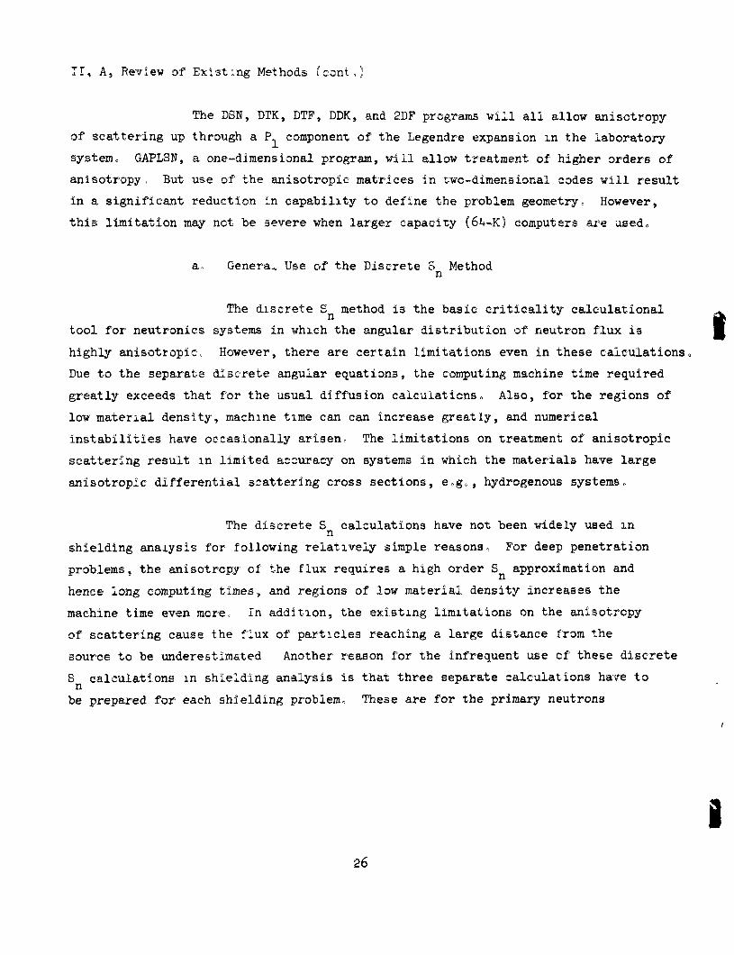
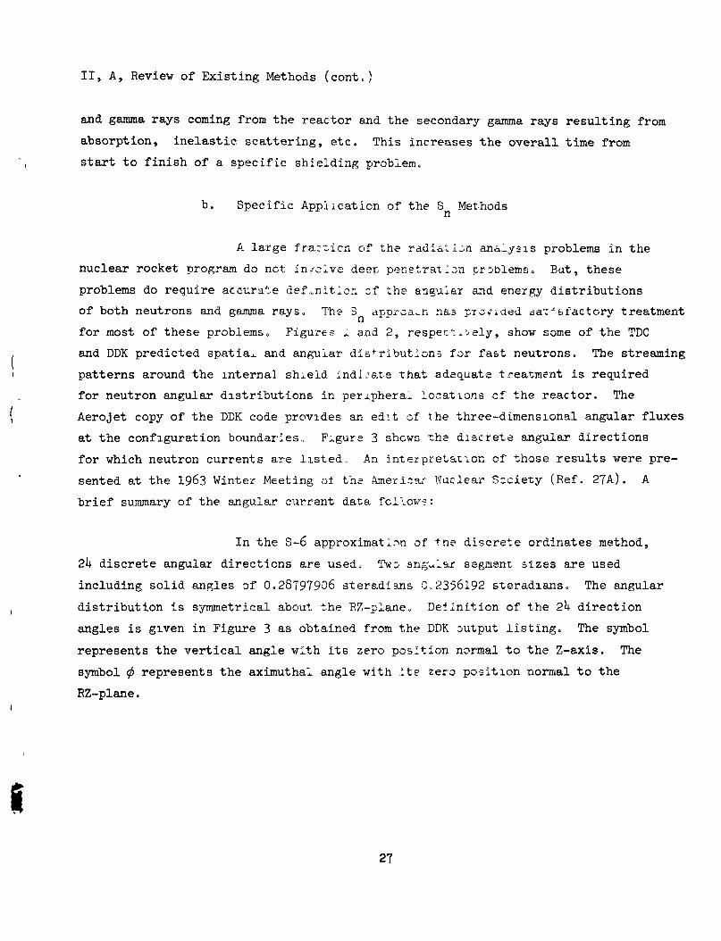
b. Specific Application of the S Methods n
A large fraction of the radialijn analysis problems in the
nuclear rocket program do not Involve deep penetration problems. But, these
problems do require accurate def...nitlcri of the angular and energy distributions
of both neutrons and gamma rays. The 3 approa..n nas pro»'ided cat* bfactory treatment
for most of these problems. Figureis I and 2, respectively, show some of the TDC
and DDK predicted spatiax and angular distributions for fast neutrons. The streaming
patterns around the internal shield indi. ate that adequate treatment is required
for neutron angular distributions in peripheral locations of the reactor. The
Aerojet copy of the DDK code provides an edit of the three-dimensional angular fluxes
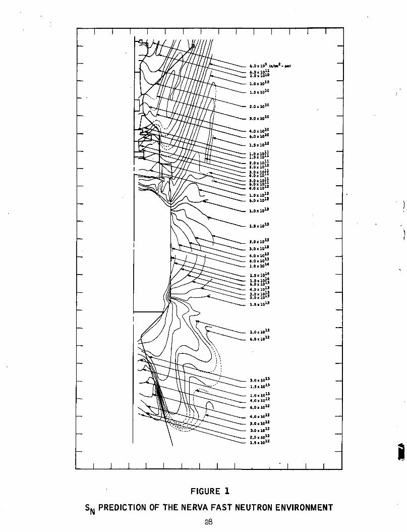
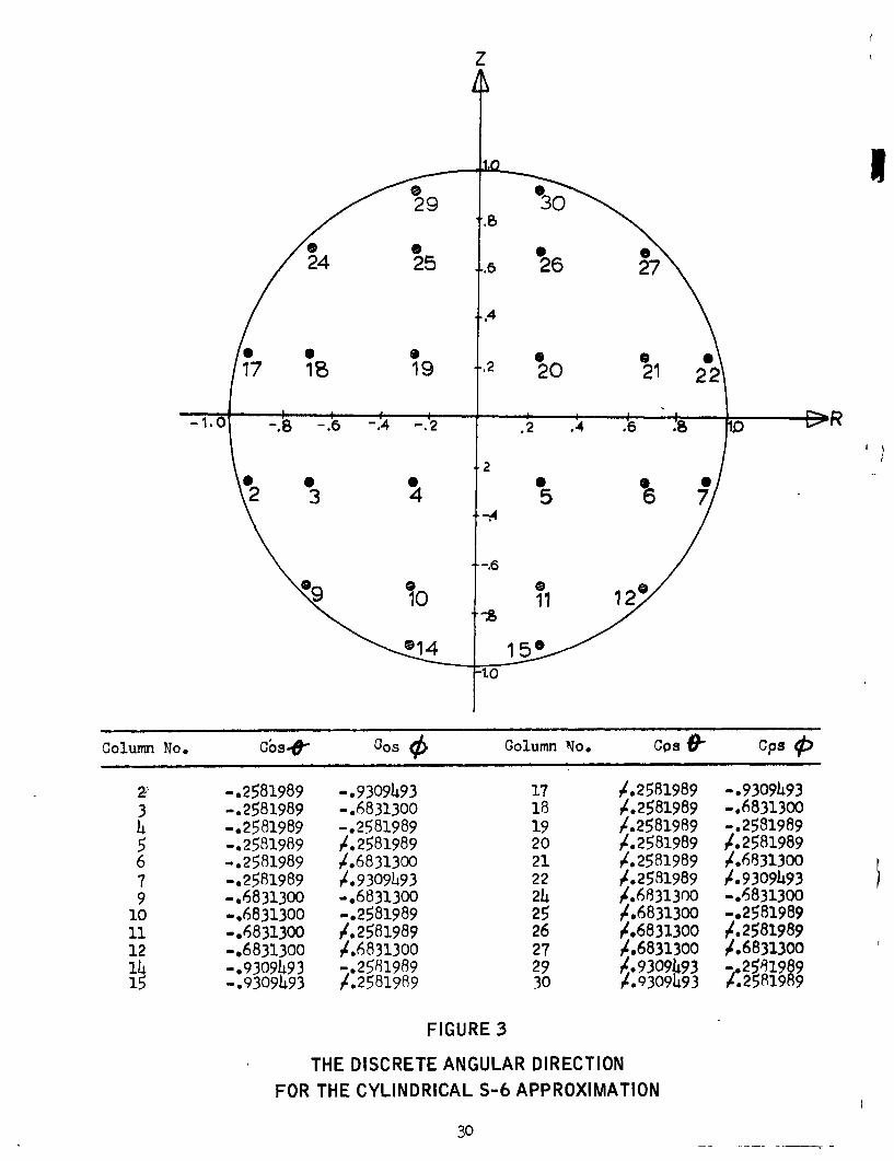
at the configuration boundaries. Figure 3 shows the discrete angular directions
for which neutron currents are listed. An interpretation of those results were pre
sented at the 1963 Winter Meeting of ths Amerisar Nuclear Scclety (Ref. 27A). A
brief summary of the angular current data fcilov?:
In the S-6 approximation of the discrete ordinates method,
2k discrete angular directions are used. TWD ang-ular segment sizes are used
including solid angles of 0.28797906 steradians 0.2356192 steradians. The angular
distribution Is symmetrical about the RZ-plane. Definition of the 2k direction
angles is given in Figure 3 as obtained from the DDK output listing. The symbol
represents the vertical angle with its zero position normal to the Z-axis. The
symbol 0 represents the aximuthal angle with its zero position normal to the
RZ-plane.
27
6.0x10^ (a/Ml'-MO)
12 1.0 > U
1.5 KIO"
nlO
3.0 K 10 10
4 .0«10' t.O >10^
1.5 K 10^'
1.0 >io}} 1.5«10** 2.0 xio}^ 2.0 « 1 0 " S.OxloH 4.0x10** 5.0 X loH 6.0 X l O " 4.0x10 1,0x10; 6.0 » 10
1.0x10 M
1.5x10 15
2.0x10
5.0x10 4.0 x i o " 6 . 0 x 1 0 " 1.0x10**
1.5x10 1.0x10 6.0 X lO*' 4.0 XIO" 3.0xl0t« 2.0x10**
13 l.SxlO
l.O X 10**
6.0 X 10**
5.0 X l o " 1.5 X l o "
1.0 X l o " 4,0 X 10*
6.0x10*
4,0x10
5.0x10
5.0 X 10*'
2 . 0 . 1 0 "
J L
FIGURE 1
S^ PREDICTION OF THE NERVA FAST NEUTRON ENVIRONMENT
28
RE
LATI
VE
N
EUTR
ON
C
UR
RE
NT
> X > r •0
o > r o
ff)
m
> o
-I o
70
70
> > r irt c :n
•n
> o m
o
FIGURE 2
RELATIVE NEUTRON CURRENT ALONG REACTOR RADIAL SURFACE
29
I
^ R
Column No,
2' 3 h $ 6 7 9
10 11 12 lU 15
Cbs-^
-.2581989 -.2581989 -.2581989 -.2531989 -.2581989 -.2581989 -.6831300 -.6831300 -.6831300 -.6831300 -.9309U93 -.9309U93
Gos <T> Column No.
-.9309U93 -.6831300 -.2581989 /.2581989 /.6831300 /.9309U93 -.6831300 -.2581989 / . 2581989 /.6831300 -.2581989 /.25819B9
FIGURES
17 18 19 20 21 22 2U 25 26 27 29 30
C o s ^
/.2581989 /.2581989 /.2581989 /.2581989 /.2581989 /.2531989 /.6831300 /,6831300 /,6831300 /.683130O /.9309U93 /.9309U93
Cps (h
-.9309U93 -.6831300 -.2581989 /.2581989 /.683130O /.9309li93 -.6831300 -.2581989 / . 2581989 /.6831300 -.2581989 /.2581989
THE DISCRETE ANGULAR DIRECTION FOR THE CYLINDRICAL S-6 APPROXIMATION
30
II, A, Review of Existing Methods (cont.)
The three paired curves in Figure 3 having crossover points
near the 135 cm axial position, define the neutron angular distribution in the RZ-plane.
The leakage neutron distribution near 135 cm is symmetrical about a line normal to
the reactor surface. But in any other position, the leakage currents are biased
in either the upward or downward direction.
Another application is the S treatment of neutron n
thermal!zation and spectrum prediction in various media. This has been found to be
particularly successful in predicting secondary gamma generation rates in shielding
media. These secondary gamma generation rates are then input to a point kernel code
such as QAD-Q5 to determine the resulting contributions from secondaries.
In addition, the discrete ordinates methods are useful in
predicting gamma ray distributions. Recent work (Ref. 28) has shown them to be in
excellent agreement with Monte Carlo predictions for gajjima ray spectra.
One of the major problems in calculating large systems with
the discrete ordinates method is the lack of sufficient memory in computing machines.
The best results are obtained by using as many mesh intervals as possible to describe
the analytical model without exceeding available memory. This is a trial-and-error
scheme for many users of the discrete ordinates method.
At Aerojet, a technique has been devised for predicting the
memory requirements as a function of all the input parameters. An example of
this technique is shown in Figure k. With this technique, the problem size can
be adjusted as appropriate to maJke full use of available computer memory.
I 31
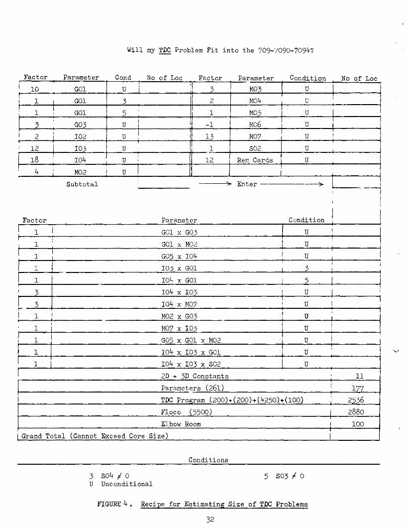
Will my TDC Problem Fit into the 709-7090-709^?
Factor Parameter
10 GOl
Cond No of Loc Factor
U 3
Parameter Condition , No of Loc
M03 U
GOl mk GOl M03
G03 U M06
102 13 M07
12 103 u S02
18 I04 12 Rem Cards U
M02 U
Subtotal .^ Enter
Factor Parameter Condition
GOl X G03
GOl X M02
G03 X 10^ U
103 x GOl
10^ X GOl
10^ x 103 U
10^ x M07
M02 X G03
M07 X 103
G05 X GOl X M02
U
10^ X 103 X GOl
10^ X 103 X S02
2D + 3D Constants 11
Parameters (26l)
TDC Program (200)+(200)+(4250)+(l00)
177
2336
Floco (3300) 2880
Elbow Room 100
Grand Total (Cannot Exceed Core Size)
Conditions
3 S0i+ / 0 U Uncondi t ional
5 S03 / 0
FIGURE k , Recipe for Estimating Size of TDC Problems
32
II, A, Review of Existing Methods (cont.)
k. Diffusion Theory Methods
The diffusion theory method for radiation analysis has a very
limited application. It cannot treat problems containing void regions nor problems
involving thick shields. Its principal application in shielding analysis is the
prediction of fission power, neutron flux, and neutron capture distributions within
the reactor proper and the prediction of infinite media spectra for flux weighting
calculations in generating multi-group neutron cross sections.
It is unlikely that any of the diffusion theory codes will be
selected as part of the recommended shielding package except as they might exist
as an integral part of a cross section code. All of the diffusion theory calculations
can be performed equally and better by the S transport method, though at some
modest added expense. However, the additional expense is small when considering
the speed of current computing machines and the frequency that diffusion theory
methods can be used reliably.
5. Auxiliary Programs
A number of auxiliary programs are required to prepare and check
input data and to process output data. Some of the more important ones currently in
use at Aerojet are described in this section. These include the gamma scattering
code GGG, the geometric configuation plotter GECOP, the data reduction codes RTDCO
and RQADO, and cross section codes.
a. Los Alamos Program GGG (Ref„ 29)
Program GGG is designed to evaluate gamma scattering from
regions surrounding a point isotropic gamma source. The collision density is
evaluated on the basis of the un-collided flux. The dose rate at the detector is
evaluated by use of the Kleln-Nishlna scattering distribution and the application of
a buildup factor in the attenuation along the second leg of the gamma path.
33
II, A, Review of Existing Methods (cont.)
The code requires information on collision coordinates, the
material distributions that interpose the rays that connect the source, scatter
point, and detector. The geometry routine is identical with that of QAD-P5o
b. Geometric Configuration Plotter
The shielding codes currently m use at Aerojet require speci
fication of geometric configurations by use of coefficients to the expression shown
below.
A(X-X )^ + B(Y-Y )^ + C(Z-Z )^ = K o o o
One of the major problems of using this form of geometric speci
fication is that errors are seldom immediately evident. These may be key punch errors,
transcription errors, or engineering errors that define configurations significantly
different from the desired configuration.
For assurance that the input coefficients actually describe
the desired analytical model, a program (GECOP) has been written by Aerojet, which plots
the configuration defined by the selected coefficients.
A photo-reduced copy of a typical plot is shown in Figure 5
which is the configuration defined by the abstract coefficients listed in Table II
and III. Originals of Figure 5 are provided m a folder in the back cover of the
copies of this proposal transmitted to MSFC. This GECOP program should be Included
as part of the selected analysis method or methods.
Co Data Reduction Programs
Determining the nominal radiation environment for all components
of the NERVA engine requires the use of two-dimensional maps of the radiation distribu
tions about the reactor. Data reduction programs, such as RTDCO and RQADO, are used
to identify the location of the iso-flux or iso-dose contours on the basis of flux or
dose data at selected points m the regions of interestr
2k
t1
3 4 4 4
9 9 9 9
-28 -13 -12 -2
15 18 19 29
-13 30 30 22
18 45 45 44
29 14 13 12
46 46 17 18
-29 -21 -21
16 11 3
Table 2
16 17 18 19
Zone Description Data for Figure h
Sheet 1 of ij-
36
h h
12 12
-35 -3
31 23
17 18
26 25
3 h
24 20
-16 -16
22 22
K 4 4 4 4 4 3 3 3 4 4 4 4 4 5 4 4 4 4 4 3 4 4 4 4 4 4 4 4 4 4 4
9 9
12 12 12 12 5 5
13 13 13 13 13 13 13 13 13 13 13 13 13 9 9 14 14 9 9
15 15 14 9 9
-1 -35 -36 -37 -38 -39 -38 -39 -57 -46 -46 -57 -39 -70 -36 -71 -12 -29 -95 -95
-117 -55 -57 -54 -55 -57 -57 -54 -56 -52 -57 -51
30 31 32 33 34 37 36 37
114 64 40
114 37 41 125 127 44 16 46 46 47 51
114 53 51
114 114 53 55 52
114 50
24 24 31 43 41 45 40 44 59 73 88 88 73 89 89 80 80
-14 103 80
103 60 62 61 62 63 64 63 64 64 65 65
43 43 43 125 124 41 33 34 38 65 112 133 65 75 75 81 81 17 86 81 86 52 54 56 54 55 59 57 59 59 40 40
2 1
35 36 37 38 37 38 39 39 67 46 70 36 2 12 14 80 117 102 102 51 55 52 54 54 56 52 53 51 51 50
19 27 23 31 32 33
126 35 36 41 65 39 42 124 127 45 46 81 49
113 120 60 50 58 52 56 57 58
115 60 60 61
-23 -19 -16 -42 -40 -44
-59 -73 -65 -45 -45 -24 -22 -30 95
-118 -109
-59 -59 -60 -60 -62 -63 -61 -63 -60 -64 -59
27 28 22
126 35 36
37 38 59 34 34 29 19 17 87 98 88
37 37 50 50 51 54 52 54 50 55 37
-31 3]
Table 2
23 24
29 30 31 32 33 34 35 36 37 38 39 40 41 42 43 44 45 46 47 48
50 51 52 53 54 55 56 57 58 59 60
Zone Description Lata for Figure k Q\ Sheet 2 of i+
37
4 4 4 4 4 4 4 4 4 4 4 4 4 4 4 4 4 4 4 4 4 4 4 4 4 4 4 4 4 4 4 4 4 4 4 4 4 3
14 16 14 9 9 14 16 14 9 14 14 14 14 15 9 14 16 14 9 9 9 14 16 14 9 9 9 9 9 14 14 14 14 14 15 IS 16 9
-50 -49 -48 -47 -67 -67 -67 -67 -67 -69 -68 -67 -67 -68 -70 -70 -70 -70 -70 -67 -71 -71 -71 -71 -71 -95 -95 -95
-101 -97 -96 ^96
-100 -.99 -99 -98 -97
-110
60 61 62 63 39 39 39 39 39 71 72 39 39 72 65 66 67 68 69 40 75 76 77 78 79 46 46 46 93 91 87 97 94 92 92 97 91 46
65 65 65 65 74 75 76 77 78 37 79 86 87 86 90 91 92 93 94 88 81 82 83 84 65 104 108 109 108 105 108 108 108 108 107 106 108 118
40 40 40 40 66 67 68 69 70 80 74 73 80 73 76 77 78 79 123 112 82 83 84 85 122 87 88 48 88 93 88 86 66 88 94 92 66 47
49 48 47 46 70 70 70 70 70 70 69 68 69 69 71 71 71 71 71 72 72 72 72 72 72 102 96 102 102 101 97 99 101 100 100 100 98 111
62 63 64 38 75 76 77 78 78 123 70 71 70 70 81 82 83 84 85 116 116 116 116 116 116 113 91 113 113 89 97 94 89 93 93 93 92 99
-59 -59 -59 -59 -73 -74 -75 -76 -77 -94 -78 -78 -86 *79 -89 -90 -91 -92 -93 -87 -80 -81 -82 -83 -84
-lOS -104 -108 -104 -104 -104 -106 -105 -107 -106 -105 -105
37 37 37 37 38 65 66 67 68 79 69 69 72 71 42 75 76 77 78 70 44 81 82 63 84 47 86 87 86 86 66 96 90 95 96 90 90
Table 2
Zone Description Data for
Sheet 3 of 4
38
3 3 3 3 3 3 3 3 3 3 3 3 3 7 4 7 4 6 3 3 3 3 3 4 4 4 4 3 4 6 6 6 6 6 7 7 7 1 ^
14 14 17 14 17 9 9 14 14 14 15 15 9 13 13 13 14 13 13 13 13 13 13 14 14 13 13 5
13 18 18 18 13 13 18 18 18 13 18
-111 -112 -113 -114 -115 -116 -119 -120 -122 -124 -121 -123 -125
72 -102
57 -53 131
-126 -32 -33
-102 -34 -71 -70 -38 -37 -37 -2 127 127
-128 133 137 -88 138 138
134
98 99
100 101 102 103 113 105 109 110 106 107 108 116 48 37 57
136 111 120 118 49
119 123 70 42 124 35 43 112 114 136 136 136 40
132 132
130
118 118 118 118 118 118 80 80 80 80 80 80 80
139 80
138 64
139 80 58 58 58 58 87 87 89 89 42 89
-46 -132 -134 -132 -136 -57 135 135
47 47 47 47 47 47 81 81
116 116 116 116 116 136 81 132 59
136 116 113 113 113 113 80 80 75 75 32 75 133 130 137 130 131 114 131 131
112 113 114 115 116 117 120 121 123 125 122 124 126 -46 119 135 52
-72 131 33 34 32
119 72 71 37 36 36 71
-128 -128 133
-135 -138 139
-132 -132
100 101 102 103 104 49 106 109 110 111 107 108 117 133 105 131 58 81
136 119 121 118 105 116 122 125 31 22 44 136 136 136 114 114 132 130 130
-127 -58
-132 -63
-127
-85 -94 -41 -43
-22 131 57
132 136
-139 46
-127 -127
128 118 130 56
128
85 79 33 32
19 136 133 114 132 133 112 129 129
88
-127
80
-129 -129 -129 -129 -129 -129
57 57
39
129
106
136 136 136 136 136 136 133 133
-129
-140
-129
130 130 130 130 130 130
-142 -141
136
134
136
136 136 136 136 136 136 136 114
130
141
130
-128 140 130
136
135
136
0 0 0 0
136 114 136
99 100 101 102 103 104 105 106 107 108 109 110 111
113
115
117 1118 1119 1120 1121 122 123 124 125 126 127
Tahle 2
Zone Desc r ip t ion Data for Figure h
Sheet U of 1+
39
00
1 2 3 4 5 6 7 8 9 10 11 12 13 14 15 16 17 18 19 2" 21 22 23 24 25 26 27 28 29 30 31 32 33 ^4 35 36 37
6 6 6 6 6 6 6 6 6 6 6 6 6 6 3 3 3 3 3 3 3 3 1 + 1.0 1+1.0 2 2 2 2
961. 961. 961.
987.216 21097.067 3 3 6 6 6 6 6 6
• 1.0 + 1.0
961. 961. 961.
987.ii6 1097.067
-0.3723 -0.1443 3833. 3833. 3833, 3952. 4168,
,155 .155 .lb5 .008 ,897
-86.' -51. 122 136 172 177 177
498 76 .052 .536 .100 .000 .000
-24.65 -13.15 -6.75 -4.95 -3.85 + 0.0 +132.8 +136.71 +148.61 +152.42 +155.51 +172.85 +176.25 +179.95 +2025.0 +2209.0 +2323.24 +2450.25 +2631.69 +3636.09 +3951.38 +4096.0 +5035,0 +4670.1 3683437.18 3683437.1(3 3683437.IB 3901485.5B 4573559.3B +4651.24 +3314.30 380.0 P 400.0 o 420.0 n
-28.45 -3?.86 -68.45
2 1
2025 ZO^b 2027 2026 2029
2032 2033 2034
T a b l e 3
Boundary E q u a t i o n s D a t a f o r F i g n r e k
S h e e t 1 of 4
1+0
9tM "'^ >
0.9666 1.0978 0.1054 0.1054
- 8 0 . 6 5 5 - 8 1 . 8 1 2 - 3 6 . 4 9 - 3 0 . 3 3
- 7 3 . 4 5 - 1 5 0 . 4 5 +144.0 +196.0
- 1 8 5 . 5 - 1 8 6 . 3 - 1 8 6 . 9 - 1 8 7 . 5 - 1 8 8 . 1 - 1 8 8 . 9 - 2 5 1 . 5 - 2 5 3 . 5 - 2 5 6 . 5 - 2 5 8 . 0 - 2 5 8 . 6 - 2 6 0 . 5
17956.0 +10816.0 +10983.0 +11236.0 +18225.0 +19600.0 +60516.0 +61009.0 - 1 8 0 . 9 - 1 7 9 . 5 - 1 7 8 . 5 - 1 7 3 . 3 5 - 1 1 7 . 5 + 3 .55 +732.0 +34969.0 +35193.8 +35438.1
Table 3
Boundary Equations Data for Figure k
Sheet 2 of U
^1
76 77 78 79 80 81 82 83 84 85 86 87 66 89 90 91 92 93 94 95 96 97 98 99 100 101 102 103 104 105 106 107 108 109 110 111 112 l i s
3 3 3 3 3 3 3 3 3 3 3 3 3 1+1. 1 + 1. 1+1. 1+1. 1+1. 1+1. 6 6 6 6 6 6 6 6 S 3 3 3 3 3 3 6 6 6 6
.0
.0
.0
.0
.0 »0
+1. +1, +1. + 1. +1. +1,
>0 ,0 »0 »0 • 0 *0
-0. -0. -0. -0. -0. -0.
.4474 • 4474 .4474 .4474 .4474 .4474
-355t -356« -357, -358, -359, -360.
.24 »26 ,28 ,30 .31 .34
+35675.7 +35910.3 +36149.4 +36481.0 +71824.0 +72146.0 +72495.6 +72835.2 +73170.0 +73603.7 +93025.0 +118473.64 +119163.04 •70514. +70923. +71327, +71734. +72140. •72554. +258.5 •259.8 •260.5 •261.5 •195.5 •358*0 •359.0 +361.9 +17956.0 +18306.1 +16468.9 •19544.0 +52900.0 •68486.9 •69169.0 •258.5 •259.77 •271.2 •273.74
Table 3
Boundary Equat ions Data for Figure k
Sheet 3 of U
1+2 . . I . .
114 115 116 117 118 119 120 121 122 123 124 125 126 127 128 129 130 131 132 133 134 135 136 137 138 139 140 141 142
1.0 1.0
1.0 1.0
1226.8 1226.8
-676 -676
+285.17 •287.71 +299.14 +300.41 +16770.3 •729.5 •730.5 •791.5 •794,0 •799.1 •801.6 •805.0 •<05.7
-579.6 -670.8 -1493.5 547.3 975,6
-1951.2 1706.4
-2030.4 1616.4
-585.6 .66 241113.2 .66 173099,3
1213.2 -457.2 457.2 -547.3
Table 3
BoundEiry Equations Data fo r Figure k
Sheet U of 4
II, A, Review of Existing Methods (cont.)
These data reduction codes perform scaling, summing, and
interpolation functions using punched output data from the TDC, DDK, and QAD-5 pro-
greuns. The multi-group flux dvtmp from TDC, for example, is read back into the com
puter for scaling to the desired power level and units in order to siim the desired
groups of fluxes and to determining the coordinates of the iso-flux contours. An
example of the resulting two-dimensional contours is shown in Figure 1.
d. Nuclear data
Output results of any calculation depend, independent of
the refinement of the theory used, on the accuracy of the input data. For shielding
and reactor analysis, these input data consist of cross sections usually in a
multi-group format. Since these cross sections are formulated from basic experimental
and theoretical data. Aerojet maintains several libraries of basic nuclear data.
This is a continuing process because new or revised data must be incorporated whenever
available. The various basic data libraries are described below. Similar thermal
neutron data is available at Aerojet, but since it is of secondary importance in this
shielding program, it will not be discussed further.
(l) Differential Neutron Scattering Data Library
The Legendre expansion coefficients of the differential
scattering cross sections are required in a variety of calculation techniques,
e.g., determination of the multigroup scattering matrices, and Aerojet has written
the SPADE code to generate the first six of these coefficients in both the L and
CM systems, as well as the various lethargy moments.
All of R. Howerton's (Ref. 30) differential elastic scat
tering data have been reduced by the SPADE code, and other data are also reduced as
they are published. At the present time, this library contains the specified data as
function of energy for about 50 elements.
kk
II, A, Review of Existing Methods (cont.)
(2) Fast Neutron Cross Section Library
The basic fast neutron cross section library, which
has taken several man-years to develop to its present state, incorporates 75
subgroups of equal lethargy (zero lethargy at 10 Mev and subgroup lethargy width
of 0„25)» Data required for the library are subgroup averaged cross sections,
neutrons per fission, resonance parameters, and angular data as obtained from the
SPADE codeo
At the present time the library contains about 200
materials with formats compatible with all fast constant generating codes in use
at Aerojet.
(3) Cross Section Generation
Aerojet maintains the calculational tools to generate
cross sections, in a completely flexible and general manner, for any reactor
shielding or physics analysis« Thus, it is possible to generate group constants
utilizing the most up-to-date theory for arbitrary group spacing and flux
averaging,
The capability of generating general cross sections
is important for a number of reasons» Calculated reaction rates for any specific
region depend on the group constants which in themselves depend upon the intragroup
flux distribution. Thus, to obtain correct reaction rates, the appropriate spectrum
in the region must be used to average the group constants.
The ability to vary energy group boundaries is important,
both for economical reasons and for accuracy. In multi-dimensional problems whose
calculation time is a direct function of the number of groups, one tries to balance
U5
II, A, Review of Existing Methods (conto)
the economy of a few groups with the accuracy of many groups to obtain the desired
numbero Also, the energy regions of interest are not necessarily the same for
criticality calculations as for shielding calculations, and therefore, one set
of group specifications is usually not optimum for both.
For the shielding codes to be used in this study, MYSTIC
(Refo 31) and AN-GAM (Refo 32) will be used to generate neutron cross sections as
needed for the S codes and Monte Carlo calculations. The 20-2 to 20-5 (Refo 33)
series of computer programs will be used to generate neutron and gainma data for the
Monte Carlo Calculations»
(k) Existing Multi-group Cross Section Data
Aerojet maintains several neutron cross section libraries
for use in criticality and shielding calculations o There is a l6 group S transport
theory set, based on Go Hansen's (Ref, 3 ) energy limits which includes cross sections
for approximately 50 materials„ This set has been used in an extensive calculation
check for determining the accuracy of the fast cross section library»
There are a number of collections of gamma ray cross
sections available: 20 group gamma constants (Refo 35 and 36) have been collected and
utilized in the S codes, and there are also the tabulated gamma data of Ro A„ Mann
(Refo 37) which are presented in the Monte Carlo format.
.,6
II, Technical Discussion (cont.)
B. DEVELOPMENT OF EVALUATION CRITERIA
Comparison and critical evaluation of the candidate analysis
methods will require definition of evaluation criteria. In defining such
evaluation criteria, consideration must be given to determining the nature of
nuclear rocket radiation ginalysis problems as well as to the availability of
suitable experimental data. These considerations will contribute to the
assignment of weights or importances for the items in the evaluation criteria.
lo Preliminary Evaluation Criteria
Some of the more important items in the evaluation criteria can
be readily identified. These include l) accuracy and cost of results, 2) adequacy
as to format and as to the detail contained in the results, and 3) relative
complexity of the input data.
Accuracy of results must be evaluated relative to the accuracy
requirements. These accuracy requirements range from the 10-20^ for component
design up to factors of 5 and 10 for general radiation environment estimates.
Generally, analysis costs vary in some proportion to accuracy of
results. A large number of variables have dominant effects on this proportionality
so that it cannot be defined in any generally applicable terms. In Monte Carlo
analysis methods, costs are affected by the degree to which the specific problem
allows use of variable reduction techniques as well as the availability of schedular
time during which these techniques may be applied. In the discrete ordinates
method calculations, the choice of geometric mesh points, number of energy groups,
order of the S level, and convergence criteria have dominant effects on analysis
costo And, in point kernal method calculations, analysis costs are affected by
the number of receiver points, the number of source points, the geometric
configuration, and the niomber of energy groups. Thus, establishing definitive
relationships between accuracy and cost must set constraints on most of the above
hi
II, B, Development of Evaluation Criteria (conto)
parameters and the resulting conclusions will apply to the specific case
consideredo However, if nuclear rocket radiation analysis problems can be
characterized by certain degrees of accuracy requirements, these can affect
the comparative "goodness" of the different candidate analysis methods and
therefore should be a part of the evaluation criteria.
Adequacy of the candidate methods, as to format and to
the detail contained in the results, is the second item in the evaluation criteria.
This item refers to the convenience sind direct usefulness of the output data as
well as to whether energy and angular distributions are adequately defined.
In some cases data are given for point locations in space and
in others data are given which are integrated over volume elements in space.
Moreover, differences also exist in lanits of the output data as well as in the
scaling to specific levels of operating power.
In some gamma ray point kernal calciilations, output data are
provided for dose rates from each of the source energy groups. These data which
contain energy dependent build-up factors do not provide the gamma ray energy
distributions required in many radiation analysis problems» Thus considerations
such as these should form an important part of the evaluation criteria.
Relative complexity of the input data must aulso be considered in
the evaluation criteria. Efficient use of many of the current computer programs
often require an intimate familiarity with the computing logic. In some cases
auxiliary computer codes are required for preparation of input data as well as
interpretation of output datao Thus, while one group of analysis methods might be
given a high rating on the accuracy criterion, it could very well have a low rating
on the criterion for complexity of input data. Depending on the importances of
these criteria for nuclear rocket and nuclear electric programs, suitable weighting
factors can be assigned to each criterion. What is required, therefore, is a
survey of the radiation analysis requirement so that these weighting factors can
be defined.
1+8
II, B, Development of Evaluation Criteria (cont.)
2. Characteristic Radiation Transport Problems
As part of the effort to develop criteria for evaluation of
analysis methods, it is necessary to identify the radiation transport problems
which are characteristic of nuclear rocket and nuclear electric systems. This
information will help define the requirements and hence the evaluation criteria
for analytical methods. In addition, these characteristic problems will form the
basis for selection of test problems to be used in evaluating the effectiveness
of the more promising analysis methods.
ao Nuclear Rocket Systems
Nuclear rocket systems are characterized by high power and
short duration operation. Radiation intensities are sufficiently high to create
serious problems relative to rate effects as well as to integral effects. The
various radiation shields that must be considered include the reactor internal
shadow-shield, the LHp propellant tank, the multiple shields required in the ground
test facility, and those engine components located between the reactor and the
propellant tank.
In addition to shield design analysis, the nuclear rocket
program requires a considerable amount of radiation analysis to define nuclear
heating and dose rate distributions within the engine components. To minimize the
requirements for reactor shielding, the effects of self-shielding in the engine
components must also be considered. To date, these analyses have been performed
by the combinations of shielding programs that have been chosen by Aerojet.
(Refo 38-^^)0 A brief description of the Aerojet nuclear codes library is given
in Section VIE.
The more difficult problems encountered in these analyses
are described below. First is the problem of accounting for neutron spectra from
the point of emergence out of the reactor to the point of absorption or leakage
from the system boundaries. This requires accounting for the angular and energy
k9
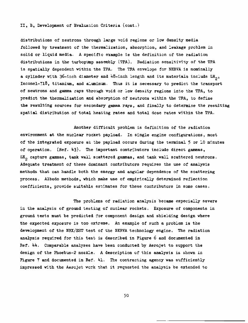
II, B, Development of Evaluation Criteria (conto)
distributions of neutrons through large void regions or low density media
followed by treatment of the thermalization, absorption, and leakage problem in
solid or liquid media. A specific example is the definition of the radiation
distributions in the turbopump assembly (TPA). Radiation sensitivity of the TPA
is spatially dependent within the TPA. The TPA envelope for NERVA is nominally
a cylinder with 36-inch diameter and lt8-inch length and its materials include LH^,
Inconel-Tl8, titanium, and aluminum. Thvs it is necessary to predict the transport
of neutrons and gamma rs^s through void or low density regions into the TPA, to
predict the thermalization scid absorption of neutrons within the TPA, to define
the resulting sources for secondary gamma rays j and finally to determine the resulting
spatial distribution of total heating rates and total dose rates within the TPAo
Another difficult problem is definition of the radiation
environment at the nuclear rocket payload. In single engine configtirations j most
of the integrated exposure at the payload occurs during the terminal 5 or 10 minutes
of operation. (Ref. ^3). Tlie important contributors include direct gammas,
LH- capture gammas, tank wall scattered gammas, and tank wall scattered neutrons.
Adequate treatment of these dominant contributors requires the use of analysis
methods that can handle both the energy and angular dependence of the scattering
process. Albedo methods, which make use of empirically determined reflection
coefficients, provide suitable estimates for these contributors in some cases.
The problems of radiation analysis became especially severe
in the analysis of ground testing of nuclear rockets. Exposure of components in
ground tests must be predicted for component design and shielding design where
the expected exposure is too extremeo An example of such a problem is the
development of the NRX/EST test of the NERVA technology engine. The radiation
analysis required for this test is described in Figure 6 and documented in
Refo kko Comparable analyses have been conducted by Aerojet to support the
design of the Phoebus-2 nozzleo A description of this analysis is shown in
Figure T and documented in Ref. 1. The contracting agency was sufficiently
impressed with the Aerojet work that it requested the analysis be extended to
50
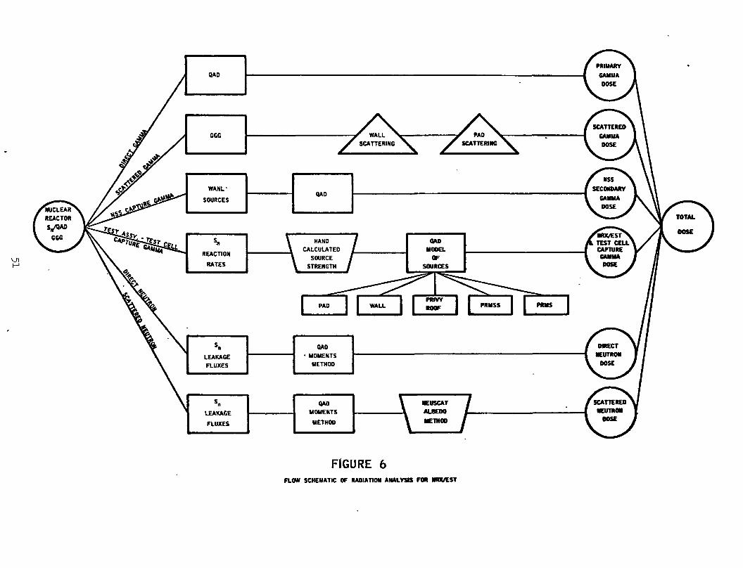
vn
QAD
GGC WALL SCATTERING
PAD SCATTERING
WANL-
SOURCES QAD
REACTION
RATES \
HAND
CALCULATED
SOURCE
STRENGTH
PAD
LEAKAGE
FLUXES
QAD
MOMENTS
METHOD
LEAKAGE
FLUXES
QAD
MOMENTS
METHOD
\ NEUSCAT /
_ A ALBEDO I— \ HEIHOD /
FIGURE 6 FLOW SCHEMATIC OF RADIATION ANALYSIS FOR RRX/EST
GAMMAS FROM FISSION EVENTS
QAD-P5 CODE
PRIMARY GAMMA RAYS
GAMMAS FROM ,, NEUTRON CAPTURE -^ ^HP'^ IN CORE MATERIALS CODE :s 80%
SECONDARY GAMMA RAYS FROM NEUTRON
CAPTURE EVENTS
/ *
CLAMSHELL SHIELD MATERIALS
NON - CORE REACTOR MATERIALS
N NOZZLE MATERIALS
NEUTRON (ABSORPTION RATES IN MATERIALS
s; 17%
QAD-P5 CODE
TOTAL
NUCLEARI HEATING RATES IN
PHOEBUS •2
NOZZLE
SCATTERED GAMMA RAYS
SCATTER FROM CORE VIA CLAMSHELL
SHIELD
FAST NEUTRON COLLISION HEATING
QAD-P5 CODE
Figure ? . Elements of Nuclear Heating in the Pboebus-2 Nozzle
II, B, Development of Evaluation Criteria (cont.)
include the pressure vessel design requirements as well. Note that the methods
used include various combinations of Monte Carlo, discrete ordinates, point kernel,
as well as auxiliary methods.
b. Nuclear Electric Systems
Nuclear electric systems are characterized by significantly
lower power levels than nuclear rocket systems, i.e., about three decades. Thus
the radiation intensities are far less hostile than those in nuclear rocket systems.
However, because of its significantly longer operating duration, i.e., three to
four decades, the tolerable radiation intensities are far below those in nuclear
rocket systems. For this reason, reliable prediction methods are equally important
for nuclear electric systems.
One of the more difficult problems is related to the radiators
of nuclear electric systems. Figure 8 provides a perspective of the SNAP-8
system. The large radiator, which is exposed to the reactor leakage flux, serves
as a scattering medium for neutrons and gamma rays as well as a significant source
of secondary gammas. These secondary gammas are produced with the absorption of
leakage neutrons in the radiator materials. As with the nuclear rocket system
problems, this radiator problem requires treatment of energy and angular distributions
in media that are separated by large void regions.
3. Collection of Suitable Experimental Data
Experimental data will be needed for evaluation of the adequacy
and accuracy of analysis results. Accuracy evaluation in many instances is performed
by comparing the results from different analysis methods and/or from different
analysis groups. Accuracy, in these comparisons, is considered adequate when there
exists some general agreement in the different predictions. When good agreement
does not exist, preference is usually given to the results generated by the more
sophisticated analysis method. However, consideration must also be given to the
53
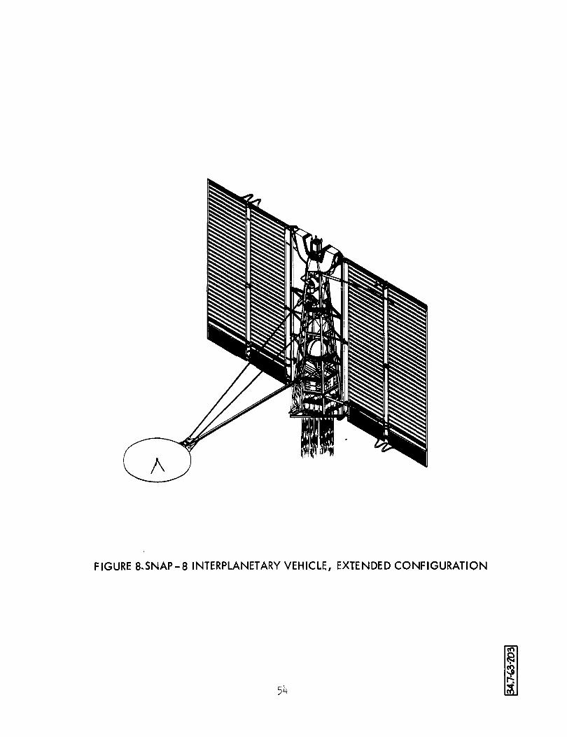
FIGURE 8.SNAP-8 INTERPLANETARY VEHICLE, EXTENDED CONFIGURATION
51*
§ ^
II, B, Development of Evaluation Criteria (cont.)
relative adequacy of the analytical models in both geometric configuration and
material compositions, and to the prediction vincertainties associated with the
degree of convergence or statistical variances.
The use of suitable experimental data provides considerable relief
to this problem of accuracy evaluation. However, it is also important to understand
the uncertainties associated with the measured data. The collection of suitable
experimental data must include definition of the conditions under which the data
were obtained as well as the various normalizations and adjustments made to the
measured data. As prime contractor for the NERVA program. Aerojet has direct
cognizance for much of the dosimetry work and therefore has the required familiarity
with the measured data.
A considerable amount of useful data have been obtained in the
course of the recent NRX/EST test conducted by Aerojet and its subcontractor,
Westinghouse. This is the first test of a combined reactor and engine system.
These measured data will allow evaluation of the methods for predicting energy and
some angular distributions of radiation about the test article.
Additional data are expected from the Phoebus-2 firings which will
more closely represent the flight configuration reactor and nozzle.
Past data taken in the course of the Kiwi-B and the NRX-A programs
are also available. Appendix A provides some comparisons between predictions and
experiment for gamma ray dose rates, neutron fluxes, and neutron spectra. These
data indicate that the analysis methods and nuclear data selected to date by Aerojet
have provided results that are in good agreement with measured data. Agreement is
good in both the spatial and energy distributions of the leakage radiation. Data
defining angular distribution, except as angular distributions affect spatial
distribution, are not yet available for comparison with prediction.
55
II, B, Development of Evaluation Criteria (conto)
Measured data will also be collected for basic configurations such
as a point source in an infinite mediumo ISiese data are well documented in the open
literatiire o
In addition, measurements obtained in the course of the SNAP-8
program and SNAP-50/SPUR program will be exploredo If available, they will be used
in the design of test problems as well as in the evaluation of prediction accuracy»
Co SELECTION OF TEST PROBLEMS
Test problems will be required for clean configurations and for actual
configtirationso Extensive amounts of reliable data exist on clean configurations
which can serve as a basic check on the suialytical method as well as on the
nuclear constants usedo
lo Basic Configuration
The final test of a calculation method for application in the analysis
of nuclear rocket and nuclear electric systems must be based on how well it
predicts radiation quantities in realistic configurationso The prediction for a
realistic system, however, is made difficult by complexity in geometry» material
distribution eaid sources of radiationso The discrepancy between calculation and
measurements are therefore the net effect of various errors of various origino
In order to help isolate the specific causes of discrepancies between generalized
calculation methods9 on the one hand, and calculational results and measurements
on the other, a conqjarison of results for "clean" basic configurations will be made.
56
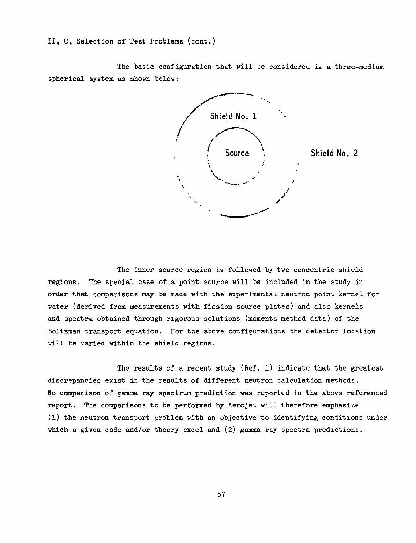
II, C, Selection of Test Problems (cont.)
The basic configuration that will be considered is a three-medium
spherical system as shown below:
Shield No. 2 JF
/
The inner source region is followed by two concentric shield
regions. The special case of a point source will be included in the study in
order that comparisons may be made with the experimental neutron point kernel for
water (derived from measurements with fission source plates) and also kernels
and spectra obtained through rigorous solutions (moments method data) of the
Boltzman transport equation. For the above configurations the detector location
will be varied within the shield regions.
The results of a recent study (Ref. l) indicate that the greatest
discrepancies exist in the results of different neutron calculation methods.
No comparison of gamma ray spectrum prediction was reported in the above referenced
report. The comparisons to be performed by Aerojet will therefore emphasize
(l) the neutron transport problem with an objective to identifying conditions under
which a given code and/or theory excel and (2) gamma ray spectra predictions.
57
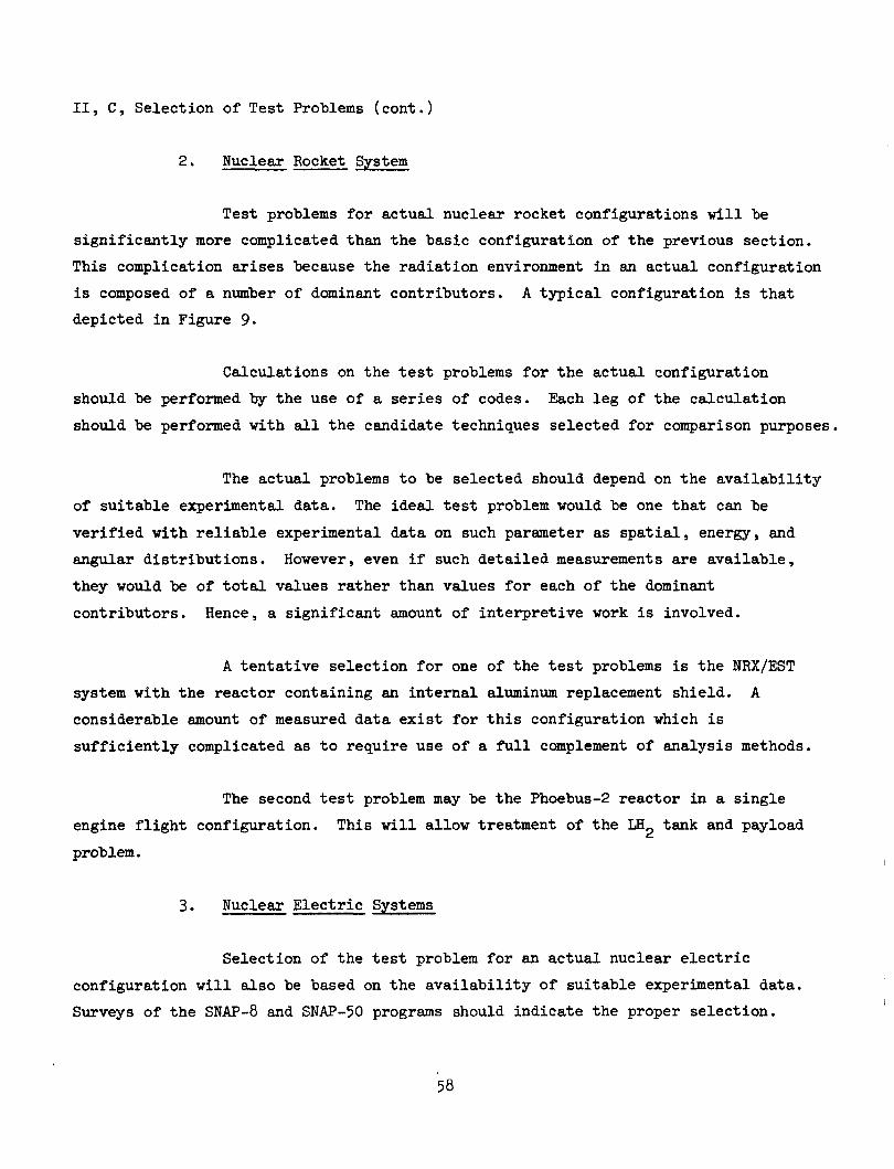
II, C, Selection of Test Problems (cont.)
2* Nuclear Rocket System
Test problems for actual nuclear rocket configurations will be
significantly more complicated than the basic configuration of the previous section.
This complication arises because the radiation environment in an actual configuration
is composed of a nxamber of dominant contributors. A typical configuration is that
depicted in Figure 9.
Calculations on the test problems for the actual configuration
should be performed by the use of a series of codes. Each leg of the calculation
should be performed with all the candidate techniques selected for comparison purposes.
The actual problems to be selected should depend on the availability
of suitable experimental data. The ideal test problem would be one that can be
verified with reliable experimental data on such parameter as spatial, energy, and
angular distributions. However, even if such detailed measurements axe available,
they would be of total values rather than values for each of the dominant
contributors. Hence, a significant amount of interpretive work is involved.
A tentative selection for one of the test problems is the NRX/EST
system with the reactor containing an internal suLuminum replacement shield. A
considerable amotint of measured data exist for this configuration which is
sufficiently complicated as to require use of a full complement of analysis methods.
The second test problem may be the Phoebus-2 reactor in a single
engine flight configuration. This will allow treatment of the LH_ tank and payload
problem.
3. Nuclear Electric Systems
Selection of the test problem for an actual nuclear electric
configuration will also be based on the availability of suitable experimental data.
Surveys of the SNAP-8 and SNAP-50 programs should indicate the proper selection.
58
6
Figure 9
Isometric of XE-Engine In ETS-1 Engine Test Compartment
59
II, C, Selection of Test Problems (cont.)
It seems quite probable that reliable data exist for the SNAP-8
configuration with an external shadow-shield. However, measurements are unlikely
for radiation scattering off of the radiator because these measurements would be
complicated by the effects of air scattering and/or facility scattering. For this
situation, comparisons may be limited to the data generated by the different
analysis methods. For improved validity a relatively large mmber of particle
histories will be examined with the preferred Monte Carlo approach.
D. CANDIDATE ANALYSIS METHODS
Candidate analysis methods are those among existing methods that can
treat the radiation analysis problems of nucleeu: rocket and nuclear electric
systems. These problems include treatment of primary gamma rays, secondary gamma
rays, scattered gamma rays, primary neutrons, and scattered neutrons.
Each of the above problems can be treated, with varying degrees of
adequacy, by use of any one of several methods. Primary gamma ray distributions,
for example, can be predicted by a number of codes in each of the point kernel,
discrete ordinates, and Monte Carlo classes of analysis methods. Likewise, a
relatively wide selection of codes is available for predicting each of the four
remaining classes of radiation analysis problems.
Thus a selection must be made of the codes that will be used for
calculations on the test problems. This selection should be made only after
completing a relatively broad literattire and field survey. Table IV provides a
tentative list of analysis methods that should be considered for performing
calculations on the selected test problems.
60
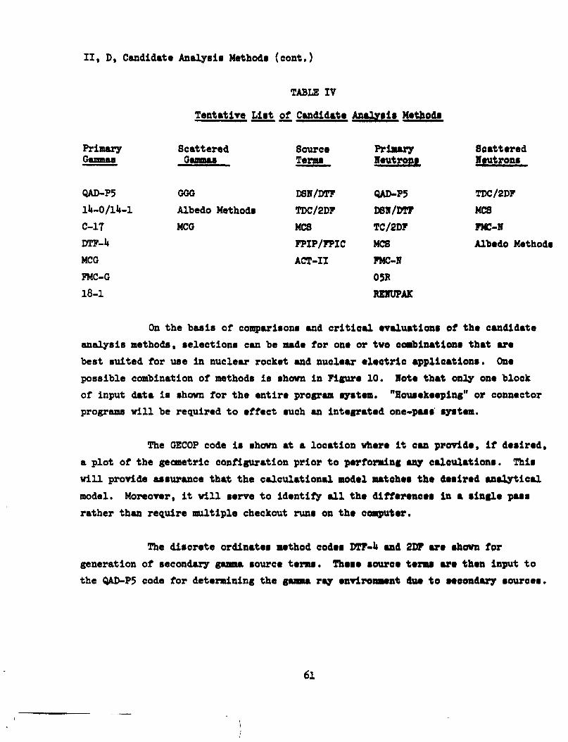
II, D, Candidate Analysis Methods (cont.)
TABLE IV
Tentative List of Candldata Analygli Mathodi
Primary Gammas
Scattered Gsmmas
Source Terms
Primary Hautrons
Scattered Wautrons
QAD-P5
ll»-0/llt_l
C-17
DTF-U
MCG
FMC-G
18-1
GOO
Albedo Methods
MCG
DSN/DTF
TDC/2DP
MC8
PPIP/FPIC
ACT-II
QAD-P5
D6H/DTT
TC/2DP
MCS
FMC-N
GSR
RZIUPAK
TDC/2DF
MCS
FMC-N
Albedo Methods
On the basis of comparisons and critical avaluatloni of tha candidate
analysis methods, selections can be made for one or tve combinations that ara
best suited for use In nuclear rocket and nuclear alaotrlo applications. One
possible combination of methods is shown In Figure 10. Note that only one block
of input data is shown for the entire program system. "Housekaaping" or connector
programs will be required to effect such an Integrated one-pass system.
The GECOP code Is shown at a location where it can provide, if desired,
a plot of the geometric configuration prior to performing any calculations. This
will provide assurance that the calculational modal matehaa tha daalrad analytical
model. Moreover, it will serve to identify all tha diffaraneas in a aingla paas
rather than require multiple checkout runs on tha computar.
The discrete ordinates method codas DTF-U and 2DF ara shown for
generation of secondary gsana source tesvs. Thoaa source tarma ara than input to
the QAD-P5 code for determining the gamma ray anvlronmant dua to aaeondary sources.
61
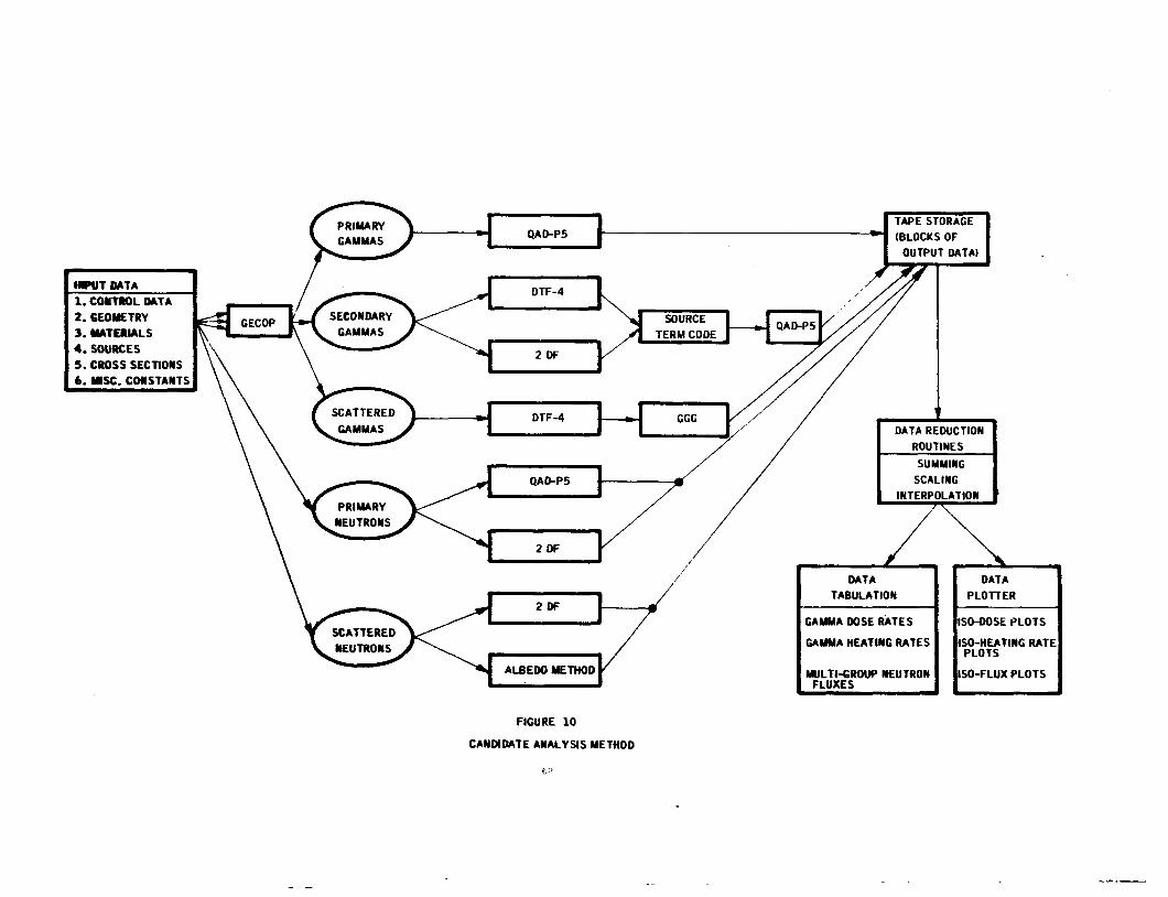
PRIMARY
GAMMAS
INPUT DATA
1 . CONTROL DATA
2 . GEOMETRY 3 . MATERIALS
4 . SOURCES
5 . CROSS SECTIONS
6 . MISC. CONSTANTS
SCATTERED
NEUTRONS
QAD-P5
DTF-4
2 OF
DTF-4
QA0-P5
2 DF
2DF
ALBEDO METHOD
TAPE STORAGE
(BLOCKS OF
OUTPUT DATA)
DATA REDUCTION
ROUTINES
SUMMING
SCALING
INTERPOLATION
DATA
TABULATION
GAMMA DOSE RATES
GAMMA HEATING RATES
MULTI-GROUP NEUTRON FLUXES
DATA
PLOTTER
ISO-DOSE PLOTS
ISO-HEATING RATE PLOTS
ISO-FLUX PLOTS
FIGURE 10
CANDIDATE ANALYSIS METHOD
II, D, Candidate Analysis Methods (cont.)
The discrete ordinates method code, DTF-U, is also used in calculations
of scattered gamma rays. In these calculations, it provides data on gamma ray
spectra for input into the GGG, single-scatter code. This spectra generator is •
an important element of the analysis method because the gamma scattering process
is very dependent on the energy distribution of the incident beam.
Another prominant feature of this combination method is its use of a
data reduction routine. This routine can operate on the blocks of data stored on
data tape for tabulation as well as plotting. The operating functions can include
scaling for the desired power level and vinits, summing to include the desired
structure for energy groups, and interpolation for identifying location of the
isodose or iso-flux contours. These data can then be listed and/or plotted as
desired.
63
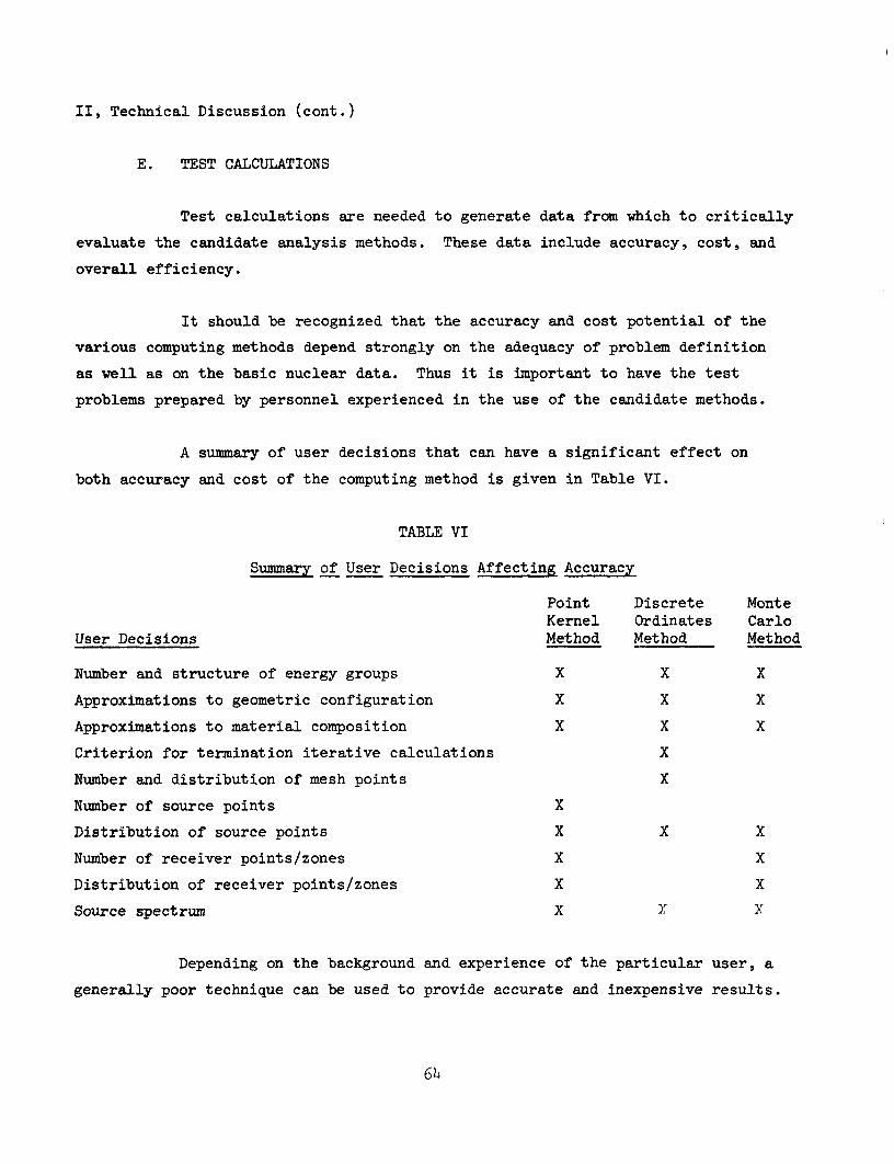
II, Technical Discussion (cont.)
E. TEST CALCULATIONS
Test calculations are needed to generate data from which to critically
evaluate the candidate analysis methods. These data include accuracy, cost, and
overall efficiency.
It should be recognized that the accuracy and cost potential of the
various computing methods depend strongly on the adequacy of problem definition
as well as on the basic nuclear data. Thus it is important to have the test
problems prepared by personnel experienced in the use of the candidate methods.
A summary of user decisions that can have a significant effect on
both accuracy and cost of the computing method is given in Table VI.
TABLE VI
Summary of User Decisions Affecting Accuracy
User Decisions
Number and structure of energy groups
Approximations to geometric configuration
Approximations to material composition
Criterion for termination iterative calculations
Number and distribution of mesh points
Number of source points
Distribution of source points
Number of receiver points/zones
Distribution of receiver points/zones
Source spectrum
Point Kernel Method
X
X
X
Discrete Ordinates Method
X
X
X
X
X
Monte Carlo Method
X
X
X
X
X
X
X
X
X
X
X
Depending on the background and experience of the particular user, a
generally poor technique can be used to provide accurate and inexpensive results.
6k
II, E, Test Calculations (cont.)
Likewise, excellent techniques can often provide very poor results if appropriate
input data were not provided. Hence to minimize the biasing effect of user
experience in this evaluation of computing methods, input data must be prepared
by personnel thoroughly familiar with the particular suialysis method.
Overall efficiency is associated with the relative ease with which
input data can be prepared and with which output data can be used. The engineering
time required to prepare input data as well as to interpret output data should be
evaluated and recorded for each of the candidate ansulysis methods. Moreover, a
problem log-book should be used containing pertinent data such as problem rvinning
time, a stimmary of results, and the information required for retrieval of the output
material. Special arrangements will be required for adequate control over these
test calculations because most of them will be performed on the MSEC computer
facility.
In regard to use of the MSEC computer, the candidate analysis programs
as well as the input data must be transferred from Aerojet to MSEC with minimum time
delays and minimiun cost. Existing auto-din equipment can be used for most of these
transfer requirements. The transmission time will be on the order of 6-hours with
negligible costs. However, the existing auto-din equipment is limited in that
binary information cannot be transmitted. This is not a serious limitation because
most of the data transfers are non-binary. Program decks and other binary data
can be shipped air-express to the MSFC computer facility. The requirement for
selected binary control information such as those contained in the DTK or DDK codes
can be replaced with BCD control information. The actual series of analysis methods
that should be used in each of the selected test problems will depend on the sxxrvey
of existing methods. The series should include candidate methods from each of the
point kernel, discrete ordinates, and Monte Carlo classes of codes as well as from
the auxiliary codes.
65
II, Technical Discussion (cont.)
F. PROGRAMMING CONSIDERATIONS
The task for devising a "one pass one system" program for solution
of radiation analysis problems has been divided into two sections for this
discussion. The first section discusses the integration of existing programs with
out significant changes from their present state and constructing connector programs
to effect the transition and thereby achieve a workable system. This discussion
includes the first three stages of work. A truly "one-system" approach with
considerations of attendant progranuning problems is discussed in Stage IV. This
second section involves the task of re-programming into FORTRAN IV.
Discussion of the programming effort is divided into four stages.
Stage I will be identified as the construction of a data reduction program in
FORTRAN IV. Stage II will be the modification of various existing radiation
analysis programs from their present state to provide appropriate output for the
data reduction program. Stage III will be the construction of a housekeeping or
connector program to permit the various component programs written in different
systems to rtm consecutively. Finally, Stage IV would involve rewriting some of
the selected programs in FORTRAN IV as appropriate.
The accomplishment of Stage I (Data Reduction Program) requires first
that the pertinent output parameters be specified. This output is to take the
form of both printed and plotted data. Existing subroutines are available for
plotting on both the CAL COMP 570 or the SC-1 020. Should the Marshall Space Flight
Center have a plotter other than the two mentioned, research would have to be per
formed to determine whether software for the Marshall plotter exists and, if so,
what the specifications for use would be.
In order to make this portion of the overall program compatible with
both editions of the composite program, primary input should be from tape and it
should be written in FORTRAN IV. The method of input gives rise to several ques
tions that will require resolution. The information that the various radiation
66
II, F, Programming Considerations (cont.)
analysis programs are currently providing must be determined. If the units of a
particular parameter contributed by the component programs differ, a standard unit
of output will have to be chosen. Typical radiation analysis output data will have
to be examined to determine the space requirements needed by the input routine.
Since some of the radiation analysis programs provide output on the basis of the
discrete ordinates method, a standard format must be developed for input of the
data to the reduction program. Considering that it will be convenient for some of
the component programs to output in row order and others in column order of multi-
subscripted arrays, the data reduction's input scheme must be developed to handle
either situation.
Development of data reduction procedures should be relatively straight
forward once the above input questions are resolved. Setting forth the display
units and the conversion thereto should pose the only remaining problem in the
development of Stage I.
Stage II involves the modification of each radiation analysis component
program so that it will output specified parameters in standard units to a common
output tape (the data reduction input). Accomplishment of this stage requires
first that a correspondence be drawn between the actual program symbol and the
desired output symbol. The flow of the program must be sufficiently researched
to ensure that the instructions for outputting to tape are placed efficiently.
An additional problem area at that point is consistency of units. If the planned
output is not in the approved units, appropriate conversions must be made. It must
also be remembered that the large size of some of the component programs may require
that the proposed tape manipulations be accomplished by a chaining method or through
the use of a post-processor program. The introduction of either method will increase
the program running time.
A workable prototype system should exist at the conclusion of Stage II
since all component programs written under the same system could be run consecu
tively and their contribution to the consolidated data tape could be added to
67
II, F, Programming Considerations (cont.)
the existing data tape as they are ran. Since essentially three systems are xinder
consideration, FORTRAN IV, FORTRAN II-FAP, FLOCO-SCAT-SAP, three separate runs
would have to be made to generate a complete data tape. The complete data tape
would then be input to the data reduction portion and subsequently yield the
desired print and plot of output data.
For consolidation into a one pass system. Stage III will require a
system constructed to receive the required input of each radiation analysis
component program, pair it with its corresponding program found on a program
storage tape, and generate the system required control cards. Additionally, in
order to conserve computer time, programs written in the same system should be
grouped together on a secondary input tape. Problem areas here are the initiation
and termination of the individual systems involved. Conflicts in physical tape
assignments of the affected systems must be circumvented also. A third major
factor to be considered is that of the method for handling tape labels (or the
absence of) in the affected systems.
Completion of the above three phases would produce a "one pass
system" with a minimum amount of disturbance to existing programs that have been
checked out.
Stage IV involves recoding appropriate parts of the system in
FORTRAN IV. A major item of consideration in evaluating the many shielding
programs currently in use is that of inconsistency in the programming system.
The spectrvim of languages used range from SAP through SCAT, FLOCO, and FORTRAN II
to FORTRAN IV. Additionally, several different computers were used in construction
of the various programs including the 70U, 709 , and the CDC 360O,
Differences in machine storage availability may require the use of
methods such as the CHAIN option. While improving problem handling capability, use
of this option increases problem running time. Reluctance to use CHAIN would
preserve problem running time but at the same time substantially reduce the size of
problems that can be handled.
68
II, F, Programming Considerations (cont.)
Differences in the machine word sizes (709'+-3600) could lead to a
difference in prediction accuracy, amount of core storage necessary, and/or
problem running time.
The selection of programs written in SAP, SCAT, or FLOCO would necessi
tate a decoding of same and a subsequent recoding in FORTRAN IV where existing
documentation is inadequate. Preliminary studies indicate a strong possibility
that some of the component radiation analysis programs selected may be in FLOCO
or in FAP. As a yardstick, the GE 15-2 programs contains 58OO instructions.
Application of a locally arrived at program construction factor of 11 instructions/hr
(1.5 FORTRAN Statements) yields a generation time of 528 hrs for the GE 15-2
program. This construction factor considers the time from problem definition
through checked out and documented program. The plus factor of working from a
checked out program in the FORTRAN IV program generation is more than offset by
the necessity of first having to decode the selected FLOCO or FAP program.
Moreover, work performed by other contractors in generating FORTRAN versions of
the FMC-N/FMC-G and DTK/DDK programs substantiates this conclusion.
FORTRAN II to FORTRAN IV conversion can be achieved with minimal
effort. Core system residence in FORTRAN IV is substantially greater than in
FORTRAN II. Consequently marginal FORTRAN II programs would have to be chained
when converted to FORTRAN IV. However, CDC FORTRAN to FORTRAN IV conversion
requires some additional amount of editing effort. Multi-statement lines and I/O
statements are examples of differences that would have to be resolved. As an
example, U9 hours of programming effort were expended by Aerojet in converting 2DF,
a CDC FORTRAN program written for the CDC 36OO, to run locally on the IBM 709^
\mder a FORTRAN IV system. Memory size incompatibilities also limit the problem
size capable of being handled.
In summary, the size and difficulty of the programming effort depends
upon the selected program mix (FLOCO, FORT II, etc.) from which the resulting
FORTRAN IV program will be constructed. However most of the more promising of
existing methods have already been converted into FORTRAN. These include the
FMC-N/FMC-G package, the TDC code, and Ihe DTK/DDK package.

I
I
III. PROPOSED PROQRAM
The objectives of this proposed program are to compare and critically
evaluate existing analysis methods In relation to their ability to meet the
analysis requirements of nuclear rocket and nuclear electric systems to select
one or two "best" combinations of methods, and to re-program these Into
FORTBAN-IV as appropriate and to conduct a seminar for M8FC personnel. Past
work reported In ER-8236, Evaluation of Methods for Computing Nuclear Rocket
Radiation Fields, will be critically reviewed and then extended to include
consideration of additional promising analysis methods in order to achieve the
program objectives.
Detailed specifications of the work to be performed, the plan of approach,
and schedules are described in this section. The proposed effort is divided into
tasks, distributed over three phases. The percentage of total technical effort
for each task is shown in Figure 11.
A. WORK TO BE PERFORMED
1. Literature search and field surveys shall be conducted to
evalxiate past work imd to collect data on existing analysis methods'.
2. Promising radiation analysis methods, additional to and including
the methods considered in Report No. ER 8236, shall be reviewed for possible
application in whole or in part for the selected analysis method.
3. Evaluation criteria for existing analysis methods shall be
defined. Consideration shall be given to radiation analysis problvu
characteristic of nuclear rocket and nuclear electric power systeau, to the use
of suitable measured data for accuracy evaluation, and to pertinent operational
characteristics of the analysis methods.
71
PHASE I
(2 MOUTHS, 12.8% OF TOTAL EFFORT.
PHASE II
(5 MONTHS, 45.7'/. OF TOTAL EFFORT)
P^ASE III
(5 MONTnS 41.57. OF TOTAL EFFORTi
/
LITERATURE AND
FIELD SURVEY
^L KEVIEW EJaSTMG M O M T I M AMLVSIS
METHODS
MSFC MPUT
lOENTIFY O K M T N ) M L CRITERIA
SELECTION OF
CANDIDATE METHODS l i TEST PROBLEMS
, SELECT AHO/DR I DEVELOP SUITABLE CROSS SECTION DATA
PERFORM CALCULATIONS
\
DEVELOP E V A L U A T W H L
CaiTEMA FOR THE A M L Y 9 S METHODS
PEFME CMRACTERISTIC MOIATHM TRANSPORT |
PHOBLEMS
I OEFME EVALUATION CRITERM
ICOLLECT SUITABLE I EXPEKHKHTAL
M T A
COMPARE AND
EVALUATE ANALYSIS METHODS
SEMINAR FOR MSFC PERSONNEL
SELECTIONS INTEGRATION OF
METHODS
RE-WRITE IN FORTRAN IV
CHECK OUT FHIAL REPORT
FIGURE 11
FLOW CHART FOR THE WORK PROCMM
Ill, A, Work to be Performed (conto)
k. Test problems shall be selected and defined for evaluating the
promising analysis methods identified by Item No. 2 above.
5. Appropriate nuclear data including multigroup neutron and
gamma ray cross sections, interaction probability data, attenuation coefficients,
and build-up factors shall be selected and/or developed for use in evaluating
the analysis methods.
6„ Perform calculations on the test problems selected in Item Noo k
with the candidate analysis methods» These shall include primary neutron and
gamma ray calculations, secondary gamma ray calculations, scattered neutron
and gamma ray calculations, eind gamma ray and neutron streaming calculations»
T. A comparison and critical evaluation of the promising analysis
methods shall be made on the basis of the criteria developed in Item No, 3o
80 A selection shall be made for one or at most two analysis
methods best suited for nuclear rocket and nuclear electric applications on
the basis of Item No. T with appropriate input from MSFC personnel. Appropriate
modifications and integration of the selected methods shall also be made.
9o The selected combinations of analysis methods shall be
re-written as required so as to obtain versions of the programs in FORTRAN-IV
language»
10o A seminar shall be conducted to provide MSFC personnel and
other personnel, as may be specified by the government, with the instructions
necessary to allow complete utilization of the selected methods at MSFCo
11. The reports to be written shall include the agreed upon
progress reports as well as an interim report, a user's manual, and a final
report«
73
Ill, Proposed Program (conto)
B„ PROGRAM APPROACH
The approach proposed for achieving the program objectives is best
shown pictorially (Fig ire ll). The program, 12-months in duration, is divided
into three phases, each of which is described below»
lo Phase I il2oQ% of total effort)
The tasks during Phase I include a literature and field storvey,
a review of existing analysis methods, definition of evaluation criteria, and
selection of candidate analysis methods and of test problems.
ao Literature and Field Survey
The proposed program will be initiated with a literat\are
and field survey to locate and identify the existing computer codes which might
be of interest to the proposed program. The object of this survey is to determine
whether some of the less popular computer codes are more efficient or contain
more efficient features than those used in current nuclear rocket and nuclear
electric programs o
Moreover, the codes evaluation study recently completed for
MSFC (Refo l) will be critically reviewed to avoid axiy imecessary duplication of completed
worko The relatively large differences in the candidate methods considered in this
study are believed to be caused by a combination of differences in basic nuclear
data as well as differences in computing techniques» The proposed approach of
performing calculations on basic configurations as well as realistic configurations
will provide a basis for identifying weaknesses in basic nuclear datao
Ih
Ill, B, Program Approach (cont o)
A field survey will also be undertaken. It will include
consultations with personnel from the Radiation and Shielding Information Center
(RSIC) of Oak Ridge National Laboratory. Computer programs of interest, that
are not currently available in the Aerojet codes library (see Section V-B),
will be acquired along with soiitable documentationc Consultations will also be
arremged, as appropriate, with radiation analysis personnel from other contractors
engaged in radiation analysis activities <, The object of these consultations
will be to identify those techniques which have been developed for different
applications emd by personnel with different backgrounds which might contain
unique feat vires that warrant evaluation in the proposed program.
bo Review of Existing Methods
The promising methods identified in the literattire and
field survey will be critically reviewed for possible inclusion in the evaluation
tasko Consideration will include the basic theory of the various methods as well as
their operational suitabilityo The various methods will be characterized as
point kernel, discrete ordinates, Monte Carlo, or some combination method. In
addition, computation schemes, convergence criteria, and availability of appropriate
input data will be consideredo Operational suitability considerations will include
geometric flexibility, complexity of input data, potential accuracy of results as
well as operational costs»
Co Definition of Evaluation Criteria
The criteria to be used in evaluating the different analysis
methods will be defined prior to performing any calculations. These evaluation
criteria will be based on the analysis requirements of nuclear rocket and nuclear
electric systems, on availability of sxiitable experimenteuL data, and on program
operational characteristics.
75
Ill, B, Program Approach (conto)
Current analysis requirements include treatment of neutron I
transport through void media followed by thermalizing and absorbing media, neutron
and gamma ray scattering in air and off of metallic stirfaces, and angular distribu
tions of neutrons emerging from the reactor surfaces» Detailed characteristics of these
and of other analysis requirements will be defined in an effort to establish criteria
on which suitability of the various analysis methods may be evaluated.
Suitable experimental data will also be collected and
evaluatedo These will include measured data on basic configurations. The
configurations on which experimental data are available include the Kiwi-B,
NRX-A, NRX/EST, Phoebus-2, and SNAP-80 Accuracy criteria will be defined on the
basis of experimental data that are considered valid and reliable.
Operational characteristics of computing methods will be d
an important consideration in defining the evaluation criteria. These will ^
include the ability to treat realistic geometries, relative ease with which
input data are prepared, and direct useability of the output data. '
All of the above considerations will contribute to a
detailed definition of the evaluation criteria. These criteria will then be
used when comparing the relative suitability of the various condidate analysis
methods o
do Selection of Candidate Analysis Methods and Test Problems
Candidate analysis methods are those which will be selected, with
MSFC participation, for use in calculating the test problems. They will include
those methods that cannot be rejected on the basis of their ability to treat realistic
nuclear rocket and nuclear electric configurations. In cases of redundancy such
as in the DSN, DTK, and DTF series of codes, a selection will be made of the most
promising methodo
76
Ill, B, Program Approach (cont.)
Test problems will also be selected, with MSFC participation,
to determine the relative suitability of the various candidate analysis methods.
These problems will include two basic configurations for evaluation of nuclear
data. These will probably be a point source problem and a plate source problem
in an infinite water medium.
Two problems representing typical nuclear rocket configura
tions will also be selected. One of these will be a flight configuration and the
other a ground test configuration. Detailed specifications for these problems will
consider the configurations for which suitable experimental data are available.
The fifth test problem will represent a typical nuclear
electric configuration. This problem may be confined to evaluation of the
radiator scattering problem of a system such as SNAP-8, since the radiation
analysis problems of nuclear rocket and nuclear electric systems are quite
comparable otherwise.
Thus Phase I of the proposed program concludes with
selection of the candidate analysis methods and test problems and with the
definition of the evaluation criteria.
2. Phase II (U^.7^ of Total Effort)
The tasks during Phase II include selection and/or development
of suitable cross section data, calculations on the selected test problems,
comparison and evaluation of the analysis methods and preparation of an
interim report summarizing these resvilts.
)
77
Ill, B, Program Approach (cont.)
a. Generation of Cross Section Data
Cross section data will be required for analysis of the
selected test problems with the candidate analysis methods. Judicious choice
of constants can lead to significant cost savings as well as improvements in
accuracy of results.
In general, the required neutron cross sections can be
selected from existing libraries of 1+, 6, l6, l8, or 2k group constants. However,
specific cases such as regions containing LH will require some additional
data for the thermal energy groups. The gamma ray group structure will contain
at least 5 groups below 2.2 Mev to properly account for the rapid variation
of attenuation coefficients with energy at the low end of the energy bound.
b. Calculations on Test Problems
Calculations with the IBM-709^ computer will be performed
principally at the MSFC Computer facility. However, some calcvilations of a checkout
nature will be performed at the Aerojet facility in order to minimize delays associated
with computer turn-around time.
The candidate analysis methods selected during Phase I will be
shipped to the MSFC computer facility for checkout. Concvirrently, arrangements will
be made for the handling of input/output data that must be transferred between MSFC
and Aerojet. The Auto-din network that currently exists at both MSFC and Aerojet
will be used to minimize the time required for transfer of the input/output data.
78
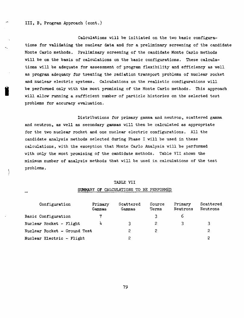
Ill, B, Program Approach (cont.)
Calculations will be initiated on the two basic configura
tions for validating the nuclear data and for a preliminary screening of the cemdidate
Monte Carlo methods. Preliminary screening of the candidate Monte Carlo methods
will be on the basis of calculations on the basic configurations. These calcula
tions will be adequate for assessment of program flexibility and efficiency as well
as program adequacy for treating the radiation transport problems of nuclear rocket
and nuclear electric systemso Calculations on the realistic configurations will
be performed only with the most promising of the Monte Carlo methods. This approach
will allow running a sufficient nvimber of particle histories on the selected test
problems for accuracy evaluation.
Distributions for primary gamma and neutron, scattered gamma
and neutron, as well as secondary gammas will then be calculated as appropriate
for the two nuclear rocket and one nuclear electric configurations. All the
candidate analysis methods selected during Phase I will be used in these
calculations, with the exception that Monte Carlo Analysis will be performed
with only the most promising of the candidate methods. Table VII shows the
minimum number of analysis methods that will be used in calculations of the test
problems.
TABLE VII
_ SUMMARY OF CALCULATIONS TO BE PERFORMED
Configuration Primary Scattered Source Primary Scattered
Gammas Gammas Terms Neutrons Neutrons
Basic Configuration 7 3 6
Nuclear Rocket - Flight k 3 2 3 3
Nuclear Rocket - Ground Test 2 2 2
Nuclear Electric - Flight 2 2
79
Ill, B, Program Approach (cont.)
Most of these calculations will be performed on the
IBM 7O9U computer at MSFCo Input data will be delivered to the MSFC computer
facility by means of an Auto-din network that currently exists at both MSFC and
Aerojet. Compatible eqixipment for this method data transfer currently exists
at both Aerojet and MSFC.
Althoxigh most of the computations will be performed on the
MSFC computer facility, checkout functions will be performed on the Aerojet
computer facility. Use of the Aerojet facility will minimize the turn-aroimd
time for the short, checkout-type problems.
c. Interim Report
The results of these calculations, comparisons, and
critical evaluations will be documented in an interim report. This report will
contain critical evaluations of the various candidate analyses on the basis of
criteria defined diiring Phase I. These criteria will include such parameters
as accuracy and adequacy of results, machine and engineering costs associated
with the calculations, and flexibility of the analysis method. The object of
this interim report is to collect, organize, and interpret the raw data in order
that an objective selection can be made, with MSFC participation, of the one or
two analysis methods best suited to nuclear rocket and nuclear electric systems.
3c Phase III (tH.3^ of Total Effort)
The third phase of the proposed program will extend over a
5-month period and will include selection and integration of analysis methods,
.•• -' rltf xT.to FORTRAN-IV, a seminar program, and a final report.
80
Ill, B, Program Approach (cont.)
a. Selection and Integration of Methods
On the basis of the data contained in the interim report
emd in consultation with MSFC, one or two of the candidate methods will be
selected. Where appropriate, desirable features from those methods not selected
will be incorporated into the selected methods.
The selected methods will, no doubt, become multiple
combinations of existing programs. The different programs will require modifica
tion for their integration into a program system of a number of independent programs.
Intermediary data processing routines will be written to
make the output data of each program compatible with the program system. Moreover,
data checking and data reduction routines will also be required. The REON
program GECOP, for example, will be incorporated into the program system to
allow checking of the problem geometry specifications. Data reduction routines
will include scaling, summing, interpolation listing, and plotting functions.
b. FORTRAN-IV Reprogramming
With exception to some of the Monte Carlo programs that might be
selected, most of the existing programs are either written in FORTRAN language or
have FORTRAN versions. However, they are written either in an older version of
FORTRAN identified as FORTRAN II or are written in the FORTRAN language for the CDC
computer rather than the IBM computer. The modifications necessary to convert
these FORTRAN systems into FORTRAN IV are relatively minor and will be undertaken as
soon as analysis method selections are made.
The Monte Carlo methods that may be selected will probably
be in either FLOCO or FAP machine language. However, if the FMC-N/FMC-G package
is selected, existing FORTRAN versions can be used. Reprogramming such systems
81
II, B, Program Approach (cont.)
as the MCS/MCG or the General Electric Program 18-1 will require about three man-
months of programming effort. Such re-programming will be performed as required
to provide versions of the selected methods in FORTRAN IV language.
c. Seminar Program
Effective utilization of the selected analysis methods
will be achieved by undertaking a seminar program. Detailed planning for this
seminar will include consideration of the character of the selected methods as
well as the familiarity of MSFC personnel with the different elements of the
selected methods.
This seminar will be most beneficial if conducted in two
or three 2-week sessions, each separated by about 2 weeks. This type of
scheduling will minimize disruption of the normal duties of MSFC personnel
as well as provide opportunity for use of the programs to solve problems
different from the test cases.
•This seminar will be conducted in parallel with the effort
to generate FORTRAN IV versions of the selected methods. This approach will allow
opportunity for MSFC technical personnel to influence the task of re-writing in
FORTRAN IV.
In general, the seminar will consist of lectvires as well
as problem solving work sessions. The lectures will include descriptions of
the various theoretical approaches as well as the limitations of the selected
approach.
The proposed interim report and User's Manual will be extremely
helpful in providing the necessary introductory information. The interim report will
contain detailed descriptions of the test problems as well as identification of the
recommended combination of analysis methods. The User's Manual will contain
instructions on prepea*ation of input data.
82
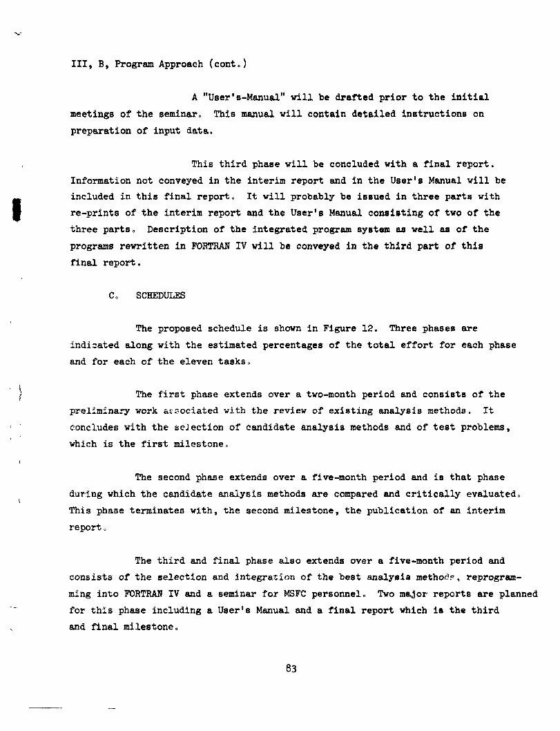
Ill, B, Program Approach (cont.)
A "User's-Manual" will be drafted prior to the initial
meetings of the seminar. This manual will contain detailed instructionB on
preparation of input data.
This third phase will be concluded with a final report.
Information not conveyed in the interim report and in the User's Manual will be
included in this final report. It will probably be issued in three parts with
re-prints of the interim report and the User's Manual consisting of two of the
three parts, Description of the integrated program system as well as of the
programs rewritten in FORTRAN IV will be conveyed in the third part of this
final report.
C. SCHEDULES
The proposed schedule is shown in Figure 12. Three phases are
indicated adong with the estimated percentages of the total effort for each phase
and for each of the eleven tasks.
The first phase extends over a two-month period and consists of the
preliminary work associated with the review of existing analysis methods. It
concludes with the seJection of candidate analysis methods and of test problems,
which is the first milestone.
The second phase extends over a five-month period and is that phase
during which the candidate analysis methods are compared and critically evaluated.
This phase terminates with, the second milestone, the publication of an interim
report.
The third and final phase also extends over a five-month period and
consists of the selection and integration of the best analysis method?, reprogram
ming into FORTRAN IV and a seminar for MSFC personnel. Two major reports are planned
for this phase including a User's Manual and a final report which is the third
and final milestone.
83
MONTHS AFTER CONTRACT AWARD
1 . LITERATURE AND FIELD SURVEY
REVIEW EXISTING RADIATION 2. ANALYSIS METHODS
3. DEFINE EVALUATION CRITERIA
4. SELECTION OF CANDIDATE ANALYSIS METHODS a TEST PRO-LEWS
SELECT AND/OR DEVELOP 5. CROSS SECTION DATA
6. PERFORM CALCULATIONS
7. COMPARE AND EVALUATE METHODS
SELECTION AND INTEGRATION 8. OF METHODS
9. FORTRAN IV RE-WRITE t CHECKOUT
10. SEMINAR FOR MSFC PERSONNEL
11 . MAJOR REPORTS
PHASE 1
1 2
1 1
PHASE II
3
>
^ ^ ™
4
r*'™
5 6 7
PHASE III
8 9 10 11 12
ESTIMATED PERCENTAGE OF TOTAL EFFORT
2.25%
4.53%
3.76'/,
2.25%
6.18%
24.70%
10.60%
8.64%
12.65%
4.98%
^
1
FIGURE 12
SCHEDULE FOR THE PROPOSED PROGRAM
81t
Ill, C, Schedules (cont.)
The indicated over-all schedule and percentage allocation of total
effort provides the necessary time and depth-of-study for achievement of the
program objectives. Although the program could be completed on an earlier
schedule, the 12-month period suggested in the Purchase Request was selected
for efficient utilization of resources.
Do REPORTS
The reports that will be published include the required monthly
progress reports and final report as well as an interim report and a User's
Manual. All of these reports will conform to the requirements of the contract.
The two additional reports are included to improve the degree to
which program objectives are achieved. The interim report will contain the
comparison and critical evaluation data. In addition to formalizing the basis
for the selection task, this report will improve the degree to which MSFC
personnel can participate in the selection of analysis methods.
The User's Manual will be written as part of the seminar task.
It will contain detailed instructions on preparation of input data as well
as operation of the program system.
E. NEW TECHNOLOGY
NASA's New Technology clause is actively supported at Aerojet Under
Contract SNP-1 which provides for the Development of the NERVA Nuclear Rocket,
REON has had a formalized program since October I96U. During this period of time,
REON has forwarded to NASA more patent disclosures than had been submitted in the
previoTis 3-1/2 year period of the Development Program. Currently, there are
approximately 50 reportable items submitted by REON in various stages of being
published as Technical Briefs or to be included in Survey Handbooks. To date, at
85
Ill, E, New Technology (cont.)
least two reportable items aire known to have been transferred to commercial use.
Since a new technology reporting system is already in being, it is not anticipated
that any additional direct charge manpower will be required in the conduct of this
proposed program. REON is also participating in New Technology reported under NASA
Contract SNP-35 for development of the Phoebus-2 Nozzle and other Aerojet divisions
are also actively participating in the Technical Utilization Program in relation
to the M-1 (NAS 23555) and the SNAP-8 (NAS-5^17) Programs which are prime contracts
with NASA Lewis Research Center.
86
IV. MANAGEMENT ORGANIZATION AND PERSONNEL
Aerojet is actively engaged in the development of nuclear rocket systems
(NERVA) as well as nuclear electric systems (SNAP-8) and recognizes the problems
associated with the integration of these systems with space vehicles. These develop
ment programs require extensive analyses to define component radiation environment
using a large complement of available analysis methods. (See Section V-B). Success
ful completion of the proposed program will help resolve many of the difficulties
currently encoxintered in the accurate predictions of radiation environment.
A. CORPORATE ORGANIZATION
The Aerojet corporate organization includes eight plant operations,
virtually autonomous, that report to the President (W. E. Zisch) through Group
Vice-Presidents A. L. Antonio and L. W. Mullane, The largest of Aerojet's facilities
is the Sacramento, California plant which is directed by Mr, R. B. Young, Vice-
President and General Manager,
Recognizing the importance of the proposed program to the continued
successful progress of the Nuclear Rocket Program, Aerojet management has chosen to
locate the responsibility for this proposed program within the Aerojet structure
where it can obtain the maximum benefit from the best managerial and technical
talent available in these unique disciplines.
The proposed program for "Synthesis of Methods f'-r Design Analysis
of Radiation Shields for Nuclear Rocket Systems" will be carried out at the
Sacramento plant by personnel of Rocket Engine Operations-Nuclear (REON) supported
as necessary by personnel from the Computing Sciences Division and the SNAP-8
Division.
The Computing Sciences Division is located at the Sacramento Plant
and provides the computing support for all of Aerojet's Sacramento operations.
The SNAP-8 Division is located at the von Karman Center of Aerojet,
87
IV, A, Corporate Organization (cont.)
REON maintains prime responsibility for the conduct of the NERVA pro
gram and all other phases of nuclear rocket technology for Aerojet under the direction
of Dr. C. C. Ross, Vice-President and Program Director. (See Figtire 13) Dr. Ross
is also Vice-President of Engineering for Aerojet-General Corporation reporting
directly to Mr. Zisch, and in this capacity, is able to influence corporate resources
to aid REON activities. Dr. Ross continuously reviews the operations and progress of
sQ.1 programs and divisions under his Jurisdiction using a highly effective program
management technique modeled after the program management system developed by the
Navy for the Polaris Program.
The proposed program will be controlled through this system of program
review with the use of wall charts and slides (which are kept ctirrent on a weekly
basis). Information from all pertinent management aids such as PERT, cost data, and
milestone charts are used to highlight deviations from the planned program. The
variables of time, resources, and technical performance form the basis for managerial
action to assure that current and potential problems are isolated in time to take
corrective action. Management can readily see the impact created by the chosen
course of action.
Dr. Ross also has at his disposal a program evaluation team that main
tains a continuing evaluation of the status of each major part of all REON programs.
This proposed program, as an element of REON efforts, will come under the surveillance
of the evaluation team. These evaluations are presented during the weekly meeting
and serve as an aid, not only to Dr. Ross, but also to his subordinates. The meeting
participants form a highly qualified technical staff, representing a wealth of
experience that can be applied to problem areas that may be presented on the proposed
program. This program management and monitoring system will benefit the proposed
effort and NASA by continuously exposing the program efforts to experienced, high
caliber review.
88
SACRAMENTO PLANT
R. 3 , YOUNG
i lCE pi^ESIDENT ^ GENERAL MANAGER
MANAGEMENT SERVICES
R. TRIPP, MGR.
ROCKET ENGINE OPERATIONS - NUCLEAR
C. C. ROSS
VICE PRESIDENT & PROGRAM DIRECTOR
COMPUTING SCIENCES DIVISION
A. W. COLE, MGR.
CONTRACTS & PROGRAM ADMINISTRATION
G. L. RYLAND, MGR.
PROGRAM MANAGER
W. D. STINNETT
COMPONENT DEVELOPMENT DIVISION
I. L. ODGERS, MGR.
ADVANCED CONCEPTS
J . L. CARTON, MGR.
TECHNOLOGY UTILIZATION
W. A. FIALA, STAFF
NUCLEAR SAFETY
J . B. PHILIPSON, MGR
PHOEBUS - 2 NOZZLE DIVISION
J . J . BEEREBOOM, MGR.
STAFF ENGINEERING DIVISION
J. H. BEVERIDGE, MGR.*
PROJECT ENGINEERING DIVISION
P. W. ROWE, MGR.
SYSTEMS ANALYSIS DIVISION
B. MANDELL, MGR.
ENGINEERING SUPPORT DIVISION
M. J. NEDER, MGR.
* PRESENTLY ASSIGNED AS PROJECT MANAGER FOR THE CONCEPTUAL DESIGN
OF THE NERVA FLIGHT ENGINE Fi:URE 13
MANAGEMENT ORGANIZATION
IV, Management Organization and Personnel (cont.)
B. PROJECT ORGANIZATION
In support of on-going programs, the REON organizational structure pro
vides for divisional-level and administrative organizations (Staff, Project, Component
Development, Systems AncLLysis, and Engineering Support). (Ref. Figure No. 13). The
managers of these divisions report to the Program Manager, Mr. W. D. Stinnett.
In addition to current programs, new technical projects of special
interest to REON report to the Program Memager as they beccnae operational. Therefore,
this program will be established as a project function within the Nuclear Analysis
Department, managed by Dr. J. A. Vreeland, reporting through the Staff Engineering
Division Manager, Mr. J. H. Severidge.
The REON Nuclear Analysis Department constitutes a significant con
centration of highly skilled radiation analysis experts. Although a relatively small
group, they offer lk5 man-years of nuclear experience, 27 of which are directly
related to nuclear rockets. Performance of this program in such a group will assure
the achievement of program objectives. Moreover, the varied technlccLL background
represented within this group assures the availability of personnel who are inti
mately familiar with all the analysis methods that are to be considered in the pro
posed program.
The proposed program will be managed by ttr. W. R. Butler, the Project
Engineer, whose attention will be devoted exclusively to this program. Moreover,
he will be the Aerojet representative on all technical matters relating to the pro
posed program.
Mr. Butler, currently Manager of Reactor Analysis, has had more than
ten years of reactor and radiation analysis experience. His recent efforts Include
radiation environment, nuclear heating, and nuclear induced activity predictions
for all components of the NERVA engine system.
9
fl
90
IV, B, Project Organization (cont.)
These analyses required application of existing Monte Carlo, Discrete
Ordinates, and point kernel methods, as well as developnent of auxiliary support
systems.
Key personnel who will assist Mr. Butler include Messrs. B. T. Klmura
and P. L. Redden. Mr. Klmura has also had more than ten years of extensive theo>
retlcal and experimental work on such programs as the nuclear ramjet and aircraft
nuclear propulsion programs. Mr. Redden has haul extensive prograoBdng experience
applicable to the requirements of this proposed program. He has programmed in SAP,
SCAT, FLOCO, FORTRAN II and FORTRAN IV for the IBM 701, 70l», and T09U series of
computers.
The relationship between the proposed project and the programming
support is shown in Figure ik. This relationship has been found to be very effec
tive in the course of the NErtVA work. Programmers who support the NERVA nuclear
analysis requirements and who are thoroughly familiar with the characteristics
of nuclear codes, will be available through Mr. Redden to support the proposed
program as required.
A partial listing of the personnel who will be assigned and avail
able to this program, and the ai)proximate percentage of time they will devote to
it, are as follows:
Walter R. Butler
Karl 0. Koebberling
Benjamin T. Kimiura
Paul L. Redden
Edward A. Warman
Duke R. Rogers
Paul Duchon
John A. Vreeland
Manager, Reactor Analysis
Nuclear Engineer
Senior Nuclear Specialist
Senior Prograasner
Manager, Shielding Analysis
Senior Nuclear Engineer
Senior Systems Engineer
Manager, Nuclear Analysis
lOOjS
50 JJ
30J{
30*
10J5
lOJf
10$
5%
Resumes for the above personnel follow.
91
COMPUTING SCIENCES
DIVISIOK
A. W. COLE, MGR.
ENGINEERING ANALYSIS
R. D. GLAUZ, MGR,
RESEARCH PROGRAMMING
P. L . REDDEN, MGR
THERMAL ANALYSIS
K. SATO, MGR.
WSFC SHIELDING PROJECT
W, R. BUTLER, MGR.
STAFF ENGINEERING
J. H. BEVERIDGE, MGR.
NUCLEAR ANALYSIS
J . A. VREELAND, MGR.
SHIELDING ANALYSIS
E. A. WARMAN, MGR.
STRESS ANALYSIS
G, KAVENEY, MGR.
REACTOR ANALYSIS
W. R. BUTLER, MGR.* B. T. KIMURA, ASST. MGR.
k/'ATERIALS
C. W. FUNK, MGR.
* FOR THE DURATION OF THE PROPOSED CONTRACT, MR. W. R. BUTLER WILL BE RELIEVED OF HIS PRESENT ASSIGNMENT AS MANAGER OF REACTOR ANALYSIS.
FIGURE 14
PROJECT ORGANIZATION
92
>
IV, B, Project Organization (cont.)
W. Ro Butler
Education
BoSo, Electrical Engineering, University of California, Berkeley, 1956
MoS,, Nuclear Engineering, University of California, Berkeley, 1957
Additional post graduate work at University of California, Berkeley as
well as Sacramento State College
Professional Experience
Aerojet, 1963 to present. Manager, Reactor Analysis Dept. Responsibility
for radiation analysis required for design of Phoebus-2 nozzle and pressure vessel
and all components of NERVA engine. In this capacity he has directed the analysis
of nuclear heat generation in the Phoebus-2 nozzle and pressxire vessel as well as
a program to maintain current data as design configurations are modified. He has
published comprehensive reports on nuclear heating, nuclear activation and nuclear
environment of the NERVA Technology engine. In addition he has provided radiation
source terms for the design of the shielding required in ground testing of the
NERVA Technology engine.
Aerojet, 1957 to 1963, Task Engineer, In this capacity Mr, Butler performed
shielding analysis for the Gas-cooled Reactor Experiment (GCRE) as well as the SNAP
systems. He also contributed to Aerojet-sponsored studies of propulsion reactors
prior to the existence of the NERVA and SNAP programs.
University of California, 1956 to 1957, Graduate Research Engineer,
Mr, Butler participated in the design of a test facility for research studies of
boiling with forced convection.
93
IV, B, Project Organization (cont.)
W. R. Butler
Publications:
A Transport Theory Analysis of a Gaseous Core Concept, W. R. Butler and
H. C. Chang, Trans. ANS 7 379 (196 +)
The NERVA Neutron Environment as Affected by the Angular Distribution of
Leakage Neutrons, W. R. Butler and J. A. Vreeland, Trans. ANS 6 (1963)
Effects of Space Radiation on Start-up of Orbit's Reactors, W, R. Butler
and D. I. Gilbert, Trans. ANS 5 (1962)
9k
IV, B, Project Organization (conto)
Paul Duchon
Education
BoS., Mathematics, Western Reserve University, 1951
M.S., Engineering Mechanics, Case Institute of Technology, I961
Certificate in EE, West Virginia University, 19**
ProfessionaJ. Experience
Aerojet, I962 to present. Senior Systems Engineer. Mr. Duchon is respon
sible for preliminary and conceptual design of power conversion systems and their
integration with spacecraft for orbital euid planetary missions. He has contributed
to SNAP-8 turbo-alternator mechanical design and studied use of SNAP-8 systems for
lunar installation as well as an earth orbiting manned space station.
Thompson nuinc-Wou' ^ riage.1957-1962, Supervisory Engineer. The design engi
neering and integration of the total power conversion system of SNAP-2 was directed
by MTO Duchon. He also supervised the design of the SNAP-1. He developed the
mathematics required in the bearing and pump tests ajnd studied numerous advanced
concepts for space power systems.
Designers for Industry, Inc., 1955-1957, Design Engineer. Mr, Duchon
developed mechanical and electrical designs for space electrical machines, systems
for oil well location, the Vanguard Satellite sequence timer, and switch gear for
facsimile transmission and receptiono
Teaching Experience. In addition to the experience described above,
Mr. Duchon has taught courses at Upland College in California, Fenn College in
Ohio amd for the Cleveland Board of Education from 195^ to 1955.
95
IV, B, Project Organization (cont.)
B. T. Kimura
Education
B.S.E., Physics, University of Michigan, 1952
A.M., Physics, University of Michigan, 195'+
Additional post graduate work at University of Oregon, 1961+ ajid 1965
Professional Experience
Aerojet, 1965 to present. Nuclear Engineering Specialist. Mr. Kimura is
responsible for the radiation analysis provided by the NERVA program to design
future test stands for ground testing of nuclear rocket engines and stages. In
addition he has made substantial contributions to Aerojet-sponsored analyses of
radiation exposure to personnel operating nuclear rocket vehicles.
Marquart, I960 to 1964, Principal Member/Advanced Technical Staff.
Mr. Kimura directed extensive theoretical and experimental programs in neutron
6uid gamma ray physics including radiation transport and detection. Design of
experiments including dosimetry and the prediction of nuclear interactions using
a linear accelerator as a source were part of this activity. Mr. Kimura was also
responsible for the radiation analysis of all nuclear systems including nuclear
ramjet engines, isotope and reactor space power sources, and NULACE (Nuclear
Liquid Air Cycle Engines). This responsibility included prediction of the
environment, and the solution of any radiation-induced problems. The design of
shielding required for controlling radiation was performed by Mr. Kimura.
Rocketdyne, 1957 to I960, Senior Research Engineer. Mr. Kim\ira conducted
radiation analysis of nuclear rocket engines comparable to NERVA. These analyses
included radiation heating of propellant and structure, shield design, and reactor
hazards evaluation.
96
IV, B, Project Organization (cont.)
B. T. Kimura
Conyair_, 195^ to 1957, Senior Nuclear Engineer. Experiments to evaluate
radiation scattering from air, ground, and structure were analyzed by Mr, Kimura.
He also evaluated additional experiments to access the effects of shield penetrations.
Engineering Research Institute, 1953 to 195^, Assistant in Research,
Mr. Kimura assisted in the development of ferromagnetic cores for tuned circuit
applications including the manufacture, evaluation, and interpretation of these
cores and their properties. He also participated in studies of inside trajectories,
radar cross sections and error analyses related to use of ballistic missiles in
defense.
Engineering Research and Development Laboratory, 1952 to 1953, Physicist,
Mr, Kimura did investigations in geometrical optics, interferometry and infra-red
spectroscopy for the development of a passive infra-red detectors.
Publications
Radiation Exposure to Crew During Operation of a Manned Nuclear Space Vehicle,
G. Garrington, B, T, Kimura, and E„ A, Warman, Aerojet Report RN-TM-O29I1,
January 1966
Radiation Analysis for the PLUTO Nuclear Ramjet Engine, Paper presented at
ARS/ANS/AIS Nuclear Propulsion Conference August 1 5 - 1 7 , I962, Monterey,
Calif,, B. T. Kimura and J, C, Saunders.
Shielding Handbook for Aircraft Designers, B, T. Kimura, ed,, Report NARF-57-20T
(FZK-9-O93), Convair, June 1957 (Classified)
Air and Groxind Scattering from the GTR; A Post Analysis, B, T, Kimura, E. Hessee,
and G. S. Weller, Report NARF 56-20T, Convair-Ft, Worth, July I965 (Classified)
Penetration of Radiation through Crew Shields, B, T. Kimura, Report NARF-56-29T,
Convair-Ft, Worth, Nov. 1956 (Classified)
97
IV, B, Project Organization (cont.)
K. 0. Koebberling
Education
B.S., Nuclear Engineering, North Carolina State University, 1958
Experience
Aerojet, 1965 to present. Nuclear Engineer. Mr. Koebberling has assisted in
calculating radiation distribution and nuclear heating for the design of Phoebus-2
and NERVA components. Use of various computer programs including Monte Carlo and
S codes were required for these analyses.
Lockheed, 1959 to 1965, Nuclear Engineer. For six years, with the Lockheed
Nuclear Products Division, Mr. Koebberling participated in numerous programs including
tank shielding of Aberdeen - OTAC, the Ohio State University, reactor and the
South American Tour reactor as well as the Reactor in Flight Test (RIFT) program.
In these programs Mr. Koebberling performed Monte Carlo shielding studies, criti-
cality calculations, control rod worth predictions, power distribution analyses,
reactor kinetics calculations, radiation effects evaluations and hazards analyses.
In addition to the use of many nuclear codes, Mr. Koebberling maintained a library
of codes and therefore made substantial contributions to Lockheed Report ER-8236,
Evaluation of Methods for Computing Nuclear Rocket Radiation Fields.
Publications
Fission Product Inventory Code, K. D. Koebberling, et al., ER-6906, May 1964
98
IV, B, Project Organization (cont.)
P. W. Redden, Jr.
Education
A.B., Mathematics, West Virginia State College, 1951
Professional Experience
Aeroj et, 1962 to present. Senior Prograimner. Mr. Redden has the responsi
bility for providing the programming support required by Aerojet in the development
of nuclear rockets. In this capacity he directs the activity of programmers in
generating new codes, in modifying and adapting existing codes to specific require
ments, and in incorporating new codes into the Aerojet system. In addition to
shielding and nuclear analysis, his activities include programming related to
trajectory aneO-ysis, component design, interior ballistics and structures analysis.
This support requires familistrity with the FLOCO system of programming as well as
FORTRAN II and FORTRAN IV.
Aerojet, 1957 to I962, Group Leader, Rocket Engine Component Development.
Direction of programming support for development of rocket engine components,
especially turbopump and nozzle designs was administered by Mr. Redden, These
codes were written for the IBM TOk and 709^ computers in SAP, SCAT, and FORTRAN II.
Engine simulation, data reduction, statistics, reliability, and structures evaluation
codes were written by this group under his cognizance.
General Electric, 195 + to 1957, Programmer, Mr, Redden developed programs
used in turbine and pump design and the reduction of test data for the IBM 701
computer.
U.S. Amqr, 1951 to 195^, First Lieutenant. Mr. Redden served in the
Artillery in Korea and as an instructor in the Artillery school.
Publications
Polaris and the Digital Computer, P. L, Redden, Polaris Training Bulletin
IV, B, Project Organization (cont.)
Do Rogers
Education
B.S. (Summa cum Laude), Engineering Physics, Univ. of Calif,, Berkeley, 1958
M.S., Nuclear Engineering, Univ. of Calif., Berkeley, 1959
(Oak Ridge Nuclear Science and Engineering Institute Fellow, 1958 to 1959)
Professional Experience
Aerojet, 1959 to present. Senior Nuclear Engineer. Mr. Rogers performs
radiation and analyses related to groiaid testing of nuclear rocket engines including
calculation of radiation scattering, nuclear heat generation, neutron activation
and predicted radiation environment. He has also conducted shielding and heat
transfer studies on the ML-1 gas cooled reactor and the MARK II AEDC (Arnold
Engineering Development Center) Environment Chamber. His ML-1 analyses included
design of fuel casks and auxiliary systems as well as shield design.
Institute of Engineering Research, 1958, Junior Engineer. Mr. Rogers con
ducted semi-theoretical research studies of nucleate boiling heat transfer.
Publications
Preliminary Evaluation of the ML-1 Shutdown Shield Performance, D, Rogers
and H. 0. Wittum, Jr., Trans ANS 6 (1963)
100
IV, B, Project Organization (cont.)
John A. Vreeland
Education
B.S., Cvim Laude, Physics, Presbyterian College, 19^9
M.A., Physics, University of Wisconsin, 1951
Ph.D., Physics, University of Wisconsin, 1955
Experience
Aerojet, 1962 to present. Manager, Nuclear Analysis Department. Dr. Vreeland,
as Manager of Nuclear Analysis is responsible for the nuclear analysis support
required throughout REON. In addition to determining the radiation environment of
the NERVA Nuclear Rocket, he directs the nuclear analysis required in the review
of facility shielding criteria, hazards docviments, shielding designs, as well as
the analyses performed in support of Advanced Concepts work.
Dr. Vreeland has participated in such non-corporate activities as Nuclear
Rocket Propulsion Symposium conducted at the University of Florida in 1962.
Rocketdyne, I96O-I962, Senior Nuclear Specialist. Dr. Vreeland was
responsible for directing the Rocketdyne efforts in the design of very large
(NOVA Second Stage) nuclear rocket engines. He also directed the necessary
reactor analysis for design of advanced nuclear rockets. Dr. Vreeland conducted
a company-sponsored 60-hour course in Nuclear Rocket Theory and course in
Modern Physics and Nuclear Physics at the University of California at Los Angeles.
Westinghouse, 1955 to I96O, Senior Nuclear Engineer. Dr. Vreeland was
responsible for the technical direction of a reactor physics group. This
involved evaluating recent cross-section measurements and predicting cross-sections
using various nuclear models of theoretical physics. Dr. Vreeland also had the
technical responsibility of reactor analysis for particularly challenging situations
101

IV, B, Project Organization (cont.)
John A. Vreeland
as exemplified by the Westinghouse Variable Loading Test Reactor as well as the
planning and execution of related experimental programs at the critical facility.
He directed the reactor kinetics program of the Pennsylvania Advanced Reactor.
University of Wisconsin, 19^9 to 1955, Research Assistant. Dr. Vreeland
conducted a research program measuring and interpreting the nuclear cross sections
of various nuclear species. Included in this program were the isotopes of Tungsten,
Tin, and Tellarium.
Publications
The NERVA Neutron Environment as Affected by the Angular Distribution of
Leakage Neutrons, W. R. Butler and J. A. Vreeland, Trans. ANS 6 (1963)
Comparisons of Some Predicted Reactivity Perturbations with Experiment,
Trans, of ANS 3 1,31 (196O)
A Reactor Fuels Measuring Facility. Trans, of ANS 2_, 2,88 (1959)
Isotope Shift in the Spectrum of WI, Journal of Physical Society of Japan
13 663 (1958)
On the Production of Experimental Quantities of Isomers, Bull, of APS 2
224 (1957)
The Hyperfine Structure of Tungsten, Physical Review 83 229 (l95l)
102
IV, B, Project Organization (cont.)
E. A. Warman
Education
B.S. Physics, Scranton University, 1956
Professional Experience
Aerojet, I963 to present. Manager Shielding Analysis Department. Mr. Warman
is responsible for analysis and shield design for the NERVA Program. These responsi
bilities include analysis and evaluation of shielding for ground tests of nuclear
rocket engines at the Nuclear Rocket Development Station (NRDS), as well as formu
lation of shielding requirements for flight systems and advanced concepts employing
nuclear rocket propulsion systems.
General Dynamics, 1958 to 1963, Shielding Engineering Supervisor. Mr. Warman
was responsible for radiation analysis, shield design, and testing in development and
construction of nuclear submarine propulsion plants for a number of POLARIS and attack-
class vessels. He was also responsible for radiation analysis and shielding studies
on General Dynamic's commercial and military sub-marine tankers, nuclear-powered
destroyers, and proposal efforts such as the MH-IA program (which employs a lOMw
reactor mounted on board a converted liberty ship for the U.S. Army Corps of Engineers
as an amphibious electrical generating system). He served as an instructor in engi
neering training programa and lectured in nuclear engineering.
He was guest lecturer in radiation shielding for senior cadets at the
U.S. Coast Guard Academy, 1961 and 1962.
Pratt and Whitney Aircraft, 1956 to 1958, Nuclear Engineer. Mr. Warman
worked in reactor physics and shielding analysis at the Connecticut Aircraft Nuclear
Engine Laboratory (CANEL) and represented Pratt and Whitney on a l4-month assignment
at the Oak Ridge National Laboratory. He was assigned to the staff of the Lid Tank
Shielding Facility of the Applied Nuclear Physics Division.
103
IV, B, Project Organization (cont.)
E. A. Warman
Publications
Neutron Radiography in Field Use, E. A. Warmsm, Materials Evaluation, Vol 23,
No. 11, November 1965
Radiation Exposure to Crew During Operation of a Manned Nuclear Space Vehicle,
E. A. Warman, et al, RN-TM-0294, January 1966
104
V. SUPPORTING INFORMATION
Aerojet's capability of performing a synthesis of shielding methods is
conveyed in this section in terms of experience accumulated in related projects
and the corporate facilities which, as a consequence, have been developed.
A. RELATED EXPERIENCE
Aerojet has an extensive background in nuclear space projects as well
as projects specifically oriented toward shielding. This experience is concentrated
in the NERVA and SNAP programs and varioxxs related efforts.
1. Nerva Program (Contract SNP-l)
As prime contractor for the NERVA program Aerojet must perform
a variety of radiation analyses intimately related to the requirements of the
MSFC shielding study. These analyses are related to the design of the engine
system as well as the individual components including the nuclear subassembly and
the specification and interpretation of the various nuclear tests conducted in
the program.
a. System Design
In addition to the NERVA engine the program includes a
sequence of developmental configurations each of which requires an analytical
prediction of its environment. In addition to the NRX configurations which are
specifically for testing the reactor, the program has considered an NRX/EST, an
XE, and an E-Engine configuration all employing an 1100 Mw Technology Engine.
The NRX/iST is the first engine test of the program and employs a close coupling
105
V, A, Related Experience (cont,)
between the turbopvimp and the reactor. Extensive shielding was required to effect
an early test of this config\iration. This shielding was designed by Aerojet to
protect the engine components and extensively analyzed to ascertain that the
requirements were met. This analysis is documented in Reference kk. The XE
configuration is similar to the NRX/EST in that the engine uses some components
that are not radiation hardened. Since this configuration is downward firing
with the turboptimp located along the axis of the engine, a different shield was
required which mates with the ETS-1 facility and which has many penetrations.
This shield was also designed by Aerojet and the required analysis including
studies of the penetrations is almost complete. A preliminary analysis is
given in Reference 42, The E-Engine is another version of the Technology Engine
except that it has a Lithium Hydride-Iron internal shield instead of an aluminum
flow simulator. It is postxilated that the engine components are radiation
hardened. Analyses of this configuration are given in References 38, 39 and 4o,
As the NERVA program evolves it is certain that additional con
figurations will be developed culminating with the ultimate 5000 Mw NERVA engine.
As the concept of this engine develops. Aerojet is constructing the necessary
models to predict the environment of this configuration as well so that the problems
of designing such a system can be resolved.
It is evident that the radiation and shielding analyses
described have the identical character of those for which a synthesis of methods
is sought. Whereas the treatment employed is not optimum in all cases, difficulties
in analysis for which acceptable solutions have been found constitute an excellent
base from which to initiate an effort to select an optimum approach.
io6
V, A, Related Experience (cont.)
b. Component Design
The design of components to operate in the intense nuclear
environment of a NERVA engine produces numerous problems. These problems are
eliminated or reduced for some components by the design of appropriate shielding.
For other components, however, the necessary relation to the reactor is such that
shielding is not possible. Even these problems are readily solved if the environ
ment can be specified within reasonable limits. Examples of such components include
the nozzle and the pressure vessel. Prediction of nuclear heat generation rates
in these components and specification of the nuclear environment with whatever
shielding is necesseoy is performed by Aerojet for all components as peo-t of the
NERVA program.
Though probably more detailed than the requirements of the
MSFC program the analyses described here have very stringent limitations on accuracy.
This experience is therefore of great value in establishing comparative precision
capabilities of various analytical techniques. The design of supplementary shielding
is directly applicable to the objectives of the MSFC program.
c. Nuclear Subassembly
The nuclear subassembly is a significant portion of the NERVA
engine, especially in the context of radiation analysis. Although Aerojet has a
strong subcontractor to manufacture this part of the engine the responsibility for
performance necessarily resides with the prime contractor. In addition to main
taining cognizance over the activity, Aerojet retains the responsibility of defining
the criteria to be met. In relation to radiation analysis the significant contribu
tion of Aerojet is identification of the function of the shielding which is part of
107
V, A, Related Experience (cont,)
the nuclear subassembly. To write criteria for this shield design Aerojet familiar
izes itself with the radiation problems associated with nuclear rockets and modifies
the objectives of the nuclear subassembly shielding to eliminate problems as they
are identified. In tests planned for the Technology Engine to date, shielding
problems are resolved using shields external to the nuclear subassembly. The
criteria for the NERVA engine shield, based on the development of a turbopump with
a zero net positive suction pressure capability, is presently to control nuclear
heating of imcooled structures.
The analyses required to establish criteria for the nuclear
subassembly shield and to evaluate the extent to which the criteria are met are
analogous to those required for system design. The existence of this effort at
Aerojet merely amplifies the depth of experience of great value in selecting and
utilizing radiation analysis methods in this program.
d. Nuclear Systems Tests
All of the configurations developed in the NERVA program
to date have been for ground testing. The radiation analyses for these systems
therefore considered all the scattered and secondary radiation resulting from
such tests. The execution of these tests nevertheless results in two additional
considerations: (l) the ability to make measurements with which to evaluate the
radiation predictions and (2) the incidence of test stand contamination from
fission products and neutron activation. For eveiy test Aerojet specifies the
dosimetry required to verify the exposure to the components and whatever additional
dosimetry is needed to improve its analytical prowess. For example, on the NRX/EST
test now being conducted. Aerojet has an experiment which exposes gamma ray and
108
V, A, Related Experience (cont.)
neutron dosimetry to: (l) the total radiation which exists on the test pad;
(2) only that radiation incident from the test itself; (3) only that radiation
which is reflected from the test cell wall; and (4) only that radiation reflected
from the test pad. These components are segregated with an ingeneous arrangement
of shields. The results of this experiment will provide an extremely demanding
test of the methods used to predict the test results. Additional measxirements
distributed throughout the complicated geometry of the test article will provide
additional bases for evaluating calculations.
The need to predict neutron activation levels at the test
pad following a test provides the development of additional calculation methods
including the distribution and spectra of incident neutrons, the thermalization
and captiu-e of the neutrons, and the decay of the radioactive products of neutron
capture. An additional experiment being performed by Aerojet in the current NRX/EST
test is the irradiation of samples taken from the shadow walls of Test Cell "A,"
Test Cell "C" and ETS-1 as well as a soil sample from the Nevada Test Site. These
samples are being exposed with measurements of the neutron flux and spectra.
They will be subjected to a thorough radio chemical analysis following the test
to improve the Aerojet technique in predicting Test Cell activation.
The critique of calculation methods that results from
comparison of predictions with measurements in the very complicated geometry is
invaluable to the program to be performed for MSFC. Such comparisons have already
improved the Aerojet approach to analysis and such improvements will certainly
continue. The value of beginning a selection of methods with many of the compari
sons already completed should not be overlooked. Some comparisons of experiment
with calculations that have been made are included in the appendix.
109
V, A, Related Experience (cont.)
e. Radiation Effects
The need to develop engine components compatible with the
NERVA environment produces a requirement to test materials in a comparable radiation
environment so that the design selections can be made with confidence. A similar
requirement to proof-test components in appropriate nuclear fluxes exists. To
support such a radiation effects testing program. Aerojet has studied all the
reactor facilities available which can approximate such flvixes. The environment
of each test is then calculated in the coiorse of specifying the test to ascertain
whether the experiment will accomplish its objective.
These calculations not only augment the Aerojet experience
with radiation having different spectra and distributions than exist in NERVA but
they also prepare Aerojet to design experiments in these facilities specifically
for evaluation of analytical methods. Although Aerojet is not proposing that such
experiments are necessary, it is possible that they might begin to appear attractive
as the program proceeds. The application of experience with a variety of radiation
sources to the MSFC program will clearly expedite the progress.
2. SNAP Program
Aerojet is the prime contractor for the SNAP-8 system for electrical
conversion. Moreover the related experience from this program is expanded by
additional studies of the system some of which are specifically related to radia
tion environment.
110

V, A, Related Experience (cont,)
a. SNAP-8 Conversion System (Contract NAS 5-4l7)
In designing the power conversion system for SNAP-8,
Aerojet must assure adequate resistance to the radiation environment. Thus
calculations are performed to predict the system environment and to establish
the shielding requirements of the system. Moreover tests are to be performed to
demonstrate system reliability in the anticipated environment.
b. SNAP-8 Shielding Analysis (Contract NAS 5-4l7)
For the SNAP-8 Program an analysi s has been performed of the
radiation distributions to be expected near the SNAP-8 reactor in a number of
realistic vehicle configurations. Particular areas of interest were neutron acti
vation, secondary gamma production, and radiation scattering from the protuberant
SNAP-8 radiators that will also be present in almost all other nuclear space power
systems. An effort was also made to select components which would be least
affected by high radiation levels. A number of different system configurations
were examined and the resulting payload dose rates calculated.
c. Aerospace Environmental Chamber (Contract AF 40(600)-953)
Under contract to the Air Force, Aerojet studied nuclear
design criteria for a large aerospace environmental chamber. Reference designs
were established for space power reactor systems (fast and epithermal) using
various conversion devices (turbo -electric, thermionic, thermoelectric). Problems
associated with environmental testing of these reactor systems in the induced space
environment of the chamber were investigated as a basis for determining the chamber
design criteria. Both neutron and gamma radiation scattering analyses were per
formed assuming single and multiple scattering in order to determine the payload
exposure and optimum positioning of the test systems in the test chamber.
Ill
V, A, Related Experience (cont,)
These studies of SNAP systems have given Aerojet a
familiarity with the problems associated with radiation analysis of the SNAP
systems and a solution to these problems that works. As with the NERVA analyses,
the specific solutions may not be optimum but the experience provides a solid basis
from which to begin the MSFC study.
3° Other Related Experience
In addition to the experience described above which relates
specifically to the requirements of the snythesis of analytical methods. Aerojet
has had extensive experience in intimately related programs. Such experience
includes design of hardware for the Los Alamos reactor tests, the design of nuclear
rocket testing facilities, related activities sponsored by Aerojet, and selected
shielding programs.
a, Phoebus-2 Nozzle Program (Contract SNP-35)
Prediction of nuclear heat generation in the large diameter
Phoebus-2 nozzle is a significant part of the design since the ability to design
without external cooling is marginal and excessive conservatism in the prediction
of nuclear heating cannot be tolerated. These calculations are complicated above
those performed for NERVA components because of the massive facility shield being
designed in the immediate proximity of the nozzle flange. Using Monte Carlo
analysis of the heat deposition from gamma radiation in the nozzle, Aerojet was
able to reduce the uncertainty in the calculated heating rates to the point where
a design without external cooling was possible. The analyses in support of this
program are documented in Reference 4l. After reviewing the Aerojet calculations
for this program, Los Alamos requested that Aerojet extend its analysis to include
the Phoebus-2 pressTore vessel as well and provide the resxilts to the manufacturer
for his design.
11?
V, A, Related Experience (cont,)
The calculation of radiation environment in support of this
program does not differ significantly from that employed in support of the design
of NERVA components. The significance of this endeavor to the MSFC program is
that the Aerojet analysis was reviewed by an independent and competent agency of
the government and not only considered adequate but worthy of use more extensive
than intended by Aerojet.
b. Facility Design
In addition to the responsibility of designing the NERVA
engine Aerojet was chosen to design the facility (ETS-l) in which the Technology
Engine is to be tested and the preliminary planning for a second similar facility
(ETS-2) (Contract SNPC-4), This design activity included a great deal more
extensive radiation analysis than that associated with the use of the facility for
a specific test. The calculations performed include operational and post-run
isodose plots, nuclear heat generation, material activation, radiation damage,
fission-product plateout, facility shielding, and nuclear hazards as related to
test stand design, site separation, and site safety. These analyses are documented
in Reference 45,
It is probably significant that when design activity on the
test stand (E/STS 2-3) intended for NERVA engines and stages was initiated. Aerojet
was requested to provide an advisor to the government to cover the nuclear aspects
of the design as well as the engine aspects. These two Aerojet representatives
are members of a team established to monitor the design effort and are the only
industrial members of the team.
113
V, A, Related Experience (cont,)
The choice of Aerojet to represent the government's interest
in the nuclear aspects of the facility design is fiirther indication that an
independent appraisal of Aerojet capability in radiation analyses related to nuclear
rockets is outstanding.
c. Company Sponsored Work
In addition to the extensive involvement of Aerojet in various
contracts requiring extensive radiation and shielding analyses. Aerojet sponsors
a considerable level of related activity with objectives defined by Aerojet,
Although studies of fluid and metalic core reactors are related, only two programs
which are directly related will be described: (l) the storing of enthalpy from
radiation absorption and (2) radiation exposure to a crew during operation of a
manned nuclear space vehicle. The first of these considers the mechanisms of
radiation absorption and attempts to predict the quantity, distribution, and
residence times of energy which is introduced without immediate thermal consequences.
The results of this activity are docimiented in Reference 46. Althoiigh the radia
tion analysis for this effort is not sophisticated, it is significant in predicting
the attenuation of radiation through the propellant especially when related to
temperatTire measurements.
The second study uses a standard model of the module for
the final stage of a nuclear system and a reasonable choice of crew compartment
configuration with its space shielding. Radiation to the crew is predicted as a
function of remaining propellant and then related to a specified operating cycle.
After a detailed consideration of radiation transmitted through the propellant
scattered from the walls of the tank and produced from neutron capt\ire in the
structure and the propellant; the exposure to the crew is evaluated. The study
concludes that, if the allowable dose to the crew from on board radiation is 10^
of that expected from space radiation, there is no weight penalty for biological
shielding associated with the use of a NERVA nuclear rocket. This study is docu
mented in Reference 43,
114
V, A, Related Experience (cont.)
The methods used in these analyses are exactly those required
to satisfy the prerequisites of the MSFC program. The additional experience gained
in performing these studies is of value to the program because of the added limita
tions to various techniques which were identified in the course of the work. While
it is again true that an optimum solution to the analytical problems may not have
been reached, an approach which does suffice in these circumstances was defined.
d. Nuclear Rocket Propulsion Systems (Contract AF 33(6l6) 552)
This study was executed before the NERVA contract. The results
are documented in Reference 47. The radiation analysis in this study is the same as
that required by the NERVA program and by the MSFC program. However Aerojet performed
this work prior to developing the powerfvil techniques that have evolved in the NERVA
work. This effort does, nevertheless, mark the beginning of the Aerojet growth in
analytical tools for studying radiation environment of nuclear rockets and is included
here to suggest how the MSFC program might have begun were Aerojet's NERVA experience
not available,
e. ML-1 Shield Design (Contract AT (10-1)-880)
Shielding against shutdown radiation was the primary objec
tive of the ML-1 shield design. A secondary objective was to reduce operational
radiation levels insofar as the reactor package weight limitations would permit.
To achieve these objectives, a series of experiments were per
formed at the Lid Tank Facility of the Oak Ridge National Laboratory in which the
proposed shield was mocked up in slab geometry. The detailed arrangement of the
selected shield configuration was established as a result of operational and shut
down measurements made at this facility.
115
V, A, Related Experience (cont,)
In addition to the Lid Tank Experiments, other tests, measure
ments, and calculations were performed to investigate other design characteristics
of the ML-1 shield. The dose rate from capture gamma sources during operation and
activation sources for shutdown conditions were then calculated using these neutron
flux distributions, Removal theory was used to calculate the fast and thermal
neutron fliax distributions in the ML-1 shield for comparison with the results of
the SNG code and Lid Tank Measurements.
ML-1 operational levels and heat generation rates were
obtained using a multi-group, multi-region, gamma ray attenuation code designed
for computing gamma-ray heating and dose rates in infinite or semi-infinite slab
shields. This code was used to calculate the operational levels measured in the
Lid Tank Experiment, using sovirce strengths calculated for each region. After it
was determined that the calculated results were in good agreement with experimental
measurements, detailed calculations were performed on the ML-1 shield.
Most of the experimental data used were obtained from ML-1
shielding experiments performed at Idaho. Measurements were made with the reactor
at various stages of disassembly (i.e., end cone, the plen\m, then baffle, then
gas duct removed and shield water drained) as the reactor operated between 0 and
1,8 Mw of thermal power. In this series of experiments, measurements were made of
photoneutron levels, radiation steaming through ducts, slots, e t c , activation, air
scattering, operational neutron and gamma levels, and the effect of changes in boron
c one ent rat i on,
The GCRE Photoneutron Production Experiment measured the
relative multiplication photoneutron dose rates were verified by experimental
measurements,
12£
V, A, Related Experience (cont.)
These analytical and experimental studies of the ML-1 shield
design (Reference 48) add significantly to the Aerojet backgroTind. The value of
this background should not be minimized, however, since continued reference to
experimental data is the essence of radiation analysis, These ML-1 calculations
increased Aerojet's capability to perform a synthesis of shield design methods very
substantially by identifying which analytical techniques perform acceptably in given
circumstances.
B. LIST OF OPERATIONAL DIGITAL COMPUTER CODES
The digital computer codes for radiation analysis that are on a
production status at Aerojet are listed in Table VIII. These codes are grouped
according to analytical methodu including the point kernel, the discrete ordinates
and the Monte Carlo methods, the remaining codes, which treat gamma ray and
neutron scattering, neutron activation, fission product inventory, cross sections
data reduction, input data editing, radiation hazards and reactor kinetics, are
grouped together under aioxiliary programs. The table describes the basic theory,
geometric representation, and functional characteristics for the codes.
117
TABLE VIII
COMPUTER CODES FOR RADIATION ANALYSIS AT AEROJET
I, POINT KERNEL METHOD
Name Groups and Region
QAD-5 Multigroup gamma rays and fast neutrons Multi-region
'- l4-0 Multigroup gamma rays, A single fast neutron group, although provision is made for out-putting the neutron spectra. Multi- region
Geometry
Three-dimensional. Regions are formed by 7 types of boundary equations including both linear and quadratic equations. So\irce strength may be described either as a fimction or as distributed at various points.
Regions are formed by translating and rotating rectangles and trapezoids, A number of "basic" regions may be described within each "master" region. Over-lapping of region boundaries is permitted. The source strength is described in cylindrical coordinates; it is assumed independent of Q. Separate exponential and/or cosine functions describe the axial and radial distributions.
Theory Used
Gamma ray attenuation: exponential attenuation with build-up. Neutron attenuation: (a) moments method solution of the Boltzmann transport equation, (b) modified Albert-Welton version of fast neutron removal theory.
General Description and Remarks
Output may include any of the following combinations of data: Gamma ray attenuation and/or dose rate and/or spectra and/or heating rate; neutron attenuation and/or dose rate and/or spectra and/or heating rate. There is no limit on the location and number of detector points,
Gamma Ray Attenuation: Exponential attenuation with buildup. Fast Neutron Attenuation: A modification of the Albert and Welton version of fast neutron removal theory. Neutron and Gamma Ray Spectra: spectral data computed by moments method solution of the Boltzmann transport equation is input in the form of bivariant polynominal coefficients.
Output may include any combination of the following: shield weight; fast neturon attenuation and/or dose rate and/or neutron spectra; gamma ray attenuation and/or dose rate and/or spectra. Any number of dose points within or outside the shield may be specified.
I, Point Kernel Method (cont.)
Name Groups and Region Geometry Theory Used
14-1 Same as l4-0 Same as l4-0 except as follows: The source strength distribution is not assumed independent of Q nor separable in r and z; the source strength distribution is described by input-ing point values in cylindrical coordinates
Same as l4-0
l4-2 Same as l4-0
A3
Same as l4-0 except as follows: A continuous or discon-tinuovis source strength may be described by inputting point values in three-dimensional rectangular coordinates
Same as l4-0
C-17 Multi-group Multi-region
Three-dimensional Moments method and point-kernel method.
II. DISCRETE ORDINATES METHOD
DSN M\ilti-group Mxilti-region
One-dimensional: spherical, cylindrical, slab
Discrete S. transport. n
General Description and Remarks
Same as l4-0
Same as l4-0
It calculates the neutron and/or gamma spectra, heat generation rates and/or dose rate at each of a group of point detectors due to each of a group of point soxirces.
Iterates on K _, o« , concentration or geometry. Computes neutron fluxes and volume integrated reaction rates. Will also solve either the inhomo-geneous surface or volume sotirce problem. Scattering can be either isotropic or linear anisotropic.
II, Discrete Ordinates Method (cont,)
Name Groups and Region Geometry
OTK Multi-group Multi-region
One-dimensional, spherical, slab or cylindrical.
DTF-2 Multi-group neutron. Multi-region
DTF-i+ Mtilti-group gamma rays and neutrons Multi-region
One-dimensional, spherical, slab or cylindrical.
One-dimensional, spherical, slab or cylindrical
M
O TDC
2DXY
DDK
2DF
IIIo
ADONIS
Moilti-group Multi-region
Multi-group Multi-region
Multi-group Mtilti-region
Multi-group Multi-region
MONTE CARLO METHOD
Multi-group Mxilti-region
Two-dimensional, r , z
Two-dimensional, X, y
Two-dimensional: R-0, R-Z and X-Y
Two-dimensional.
Three-dimensional rectangular
Theory Used
Same as DSN.
Same as DTK.
General Description and Remarks
This code incorporates new difference equations with greater flexibility and faster calcxilational time than the DSN code.
FORTRAN version of DTK.
Gamma ray and neutron distributions based on the Boltzmajin transport equation using the S discrete ordinates method.
FORTRAN version of DTK with additional capability to study gamma ray distribution.
Discrete S transport
Discrete S
n
n transport
Similar to TDC
Same as DDK
Similar to DSN but only includes isotropic scattering.
Similar to DSN but only includes isotropic scattering.
This code incorporated all two-dimensional coordinate systems and includes both isotropic and anisotropic scattering.
FORTRAN version of DDK.
Monte Carlo It calculates the solution to the transport equation for primary neutrons or gamma rays, and their standard deviations.
Ill, Monte Carlo Method (cont.)
Name Groups and Region Geometry
FMC-N Multi-group FMC-G Multi-region
Cylindrical, spherical, slab, others
Theory Used
Monte Carlo
MCS/MCG
no
Multi-group Multi-region
Three-dimensional configuration of first and second-degree surfaces
Monte Carlo
05R Mult i -group Mii l t i - reg ion
Three-dimensional Monte Carlo
SANE- Multi-group SAGE Miilti-region
Spherical Monte Carlo
General Description and Remarks
FMC-N and G are programs which apply Monte Carlo methods to simulate neutron and gamma ray life histories, respectively, in a source shield configuration. The programs are designed for flexibility in the geometrical, material, nuclear, and source description of soxirce-shield configurations and variance reduction techniques. Output includes absorption or energy deposition tallies, leakage and entrance tallies, flux and history tallies.
Variance-reducing techniques written in FLOCO coding system is used to study the neutron and gamma penetration through shields including the scattering and reaction of neutrons on various nuclei.
It computes neutron transport with Monte Carlo method and stores the output on "collision tapes" for analysis. Separate routines are required to extract information from these tapes for use.
It solves the neutron or gamma transport problem in spherically symmetric multilayer geometry.
Ill, Monte Carlo Method (cont.)
Name Groups and Region Geometry
I8-O Multi-group Multi-region
Cylindrical, spherical, slab, others
20-2 Multi-group
20-3 Multi-group
20-1+ Miati-group
20-5 Multi-group
20-6 Multi-group
General Description and Remarks
Program 18-O is a digital computer code that applies Monte Carlo methods to simulate neutrons and gamma ray histories in reactor shield assemblies. This program is designed to investigate and determine nuclear heating rates in reactor shield systems, and neutrons and gamma ray leakage distributions in energy and angle for an equivalent point source.
Approximates cross section dependence on energy. Input for FMC-N, G and 18-0.
Computer total macroscopic cross section and collision probabilities for specified material and composition. Input for FMC-N and G, and I8-O.
Program for averaging differential scattering cross sections, Input for FMC-N and G, and 18-0,
A program for preparation of spectrtmi tables from evaporation model. Input for FMC-N and G, and 18-O,
Computes nuclear excitation and transition probabilities from measured gamma ray intensities, Input for FMC-N and G codes.
IV. NEUTRON DIFFUSION THEORY METHOD
Name Groups and Region Geometry
WANDA Few group Multi-region
One-dimens ional: spherical, cylindrical, slab
AIM-6 Multi-group Multi-region
One-dimensional: spherical, cylindrical, slab
(VI (A.)
9-ZOOM
PDQ-2
9-ANGIE
Multi-group Multi-region
Few group Multi-region
Multi-group Multi-region
V. AUXILIARY SHIELDING
One-dimensional: spherical, cylindrical, slab
Two-dimensional X, y, or r, z
Two-diemsnional, X, y, or r, z
CODES
GGG Multi-group gamma Three-dimensional Multi-region ray. Same as QAD
Theory Used
Diffusion
General Description and Remarks
Calciaates k .„ and fluxes eff
Diffusion Computes k and fluxes.
Diffusion Computes k and fluxes
Diffusion Computes k and fluxes
Diffusion Computes k and fluxes. Permits one group up scattering and two groups down scattering.
3 major processes by which the electromagnetic field of gamma ray may interact with matter are considered which include The Compton effect, photoelectric effect and pair production. For the Compton scattering the Klein-Nishina differential angular cross sections are used.
The code computes single scattering from an isotropic point source. Output includes gamma scattering and direct radiation gamma scattering and without build-up.
V, Auxiliary Shielding Codes (cont.)
Name Groups and Region Geometry
GRACE-I Multi-group M-ulti-region
Finite or semi-infinite slab, sphere, or truncated cone.
GRADE Multi-group Multi-region
Right circular cylinder and cylindrical shells
o
NGASD One group gammas, Thermal neutron group. Fast Neutron group. Multi-region
NGD-1 Multi-group (l6-group)
Two-dimensional plane geometry. Planar sovirce -any configuration
Spherical
NURSE-II Three-dimensional
Theory Used General Description and Remarks
Computes gamma ray attenuation and heating in reactor shield. Choice of uniform or exponential soiorce in multiregion slab, truncated cone or spherical shell. Choice of iniform or cosine soxirce in spheres. Buildup factor represented by a double exponential.
Calculates gamma radiation environment quantities around a nuclear rocket in a two-dimensional right circular cylinder
Emprical equations from FZK-122
NGASD calculates neutron and gamma ray air scattered dose rates in the plane of any planar soiirce at between 20 and 900 feet from the soxorce.
Diffusion equation with a point source=
Calculates neutron dose rates some distance from the reactor, and the gamma field caused by (n, y) reaction in air.
Anderson gaseous cloud growth model and Gifford's diffuson equation.
Evaluates radiation hazards resulting from the rapid release of fission products from a nuclear rocket engine. Computes several different doses at positions down- and cross-wind from an excursion point on or near the groxind. The code is written in FORTRAN IV for an IBM 'J09k with 32K memory.
V, Auxiliary Shielding Codes (cont.)
Name Groups and Region Geometry
NEUSCAT One-group Three-dimensional fast neutron
RISC Three-dimensional
ACT II Four-group
FPIP tV)
Foxir-group gamma ray
FPIC Seven-group gamma ray
9-NIOBE Miil t i-group Mul t i - r eg ion
Spherical
Theory Used
Albedo Method
0. G. Sutton's diffusion equation
Perkins and King Data
Perkins and King Data
Transport theory
General Description and Remarks
It calculates the fast neutron scattering from a plane source in a three-dimensional geometry using the Albedo method.
Computes the radiation dose to seven body organs as a result of breathing airborne radioactive material at a position down-wind tram, a reactor. Computations include cloud height and size as well as fallout and washout.
It provides gamma radiation sources in four groups from neutron activation for use in radiation level and shielding calculations.
It computes as a function of reactor operation and shutdown time, the total decay rates, total average beta energy release rate, total, gamma release rate from fission products generated in a U-235 thermal reactor.
Similar to FPIP with less isotope inventory but requires shorter machine time.
It performs numerical integration of the Boltzmann equation for neutron or gamma transport, time independent in a finite, multi-layered spherically symmetric configuration.
V, Auxiliary Shielding Codes (cont.)
Name Groups and Region Geometry
DATA REDUCTION CODES
AGMU^
AS-Tl
AUFOIL
FADE-I
FRENIC
REQADO Multi-group
Theory Used General Description and Remarks
Least square fit.
Double precision determinant
Least square fit
Does a least squares fit to a power series, or a sum of exponents, or a sum of sines, or a sum of cosines, or a sum of sines and cosines.
Solves up to UOO simultaneous algebraic equations in double precision.
The total neutron flux above a threshold energy and/or the thermal neutron flxix is calculated from discriminated gamma counting data from single radio-nuclid threshold foils.
Program designed to reduce the amount of hand calculation required to analyze foil activation data. Code analyzes foil counting data and computes foil activity and the corresponding neutron flvix. Analyzes up to 20 different power levels at irradiation.
Does a least squares fit to a simi of exponents.
Reduces the output data of QAD program. It interpolates the data and lists the results for isodose, or isocalifacio plots. The program output tape can be used directly on a plotter.
V, Auxiliary Shielding Codes (cont.)
Name Groups and Region Geometry
RTDCO Multi-group
CROSS SECTION CODES
GAM Multi-group Fast Neutrons
Theory Used General Description and Remarks
Reduces output data for both TDC and DDK. Performs scaling, suimning, and interpolation functions and identifies locations for isoflux contours.
B-1 or Calculates a spectrtmi utilizing P-1 approximation either the B-1 or P-1 approximation
or will take a read-in spectrum. Obtains group averaged constants and transfer matrices for diffusion theory, isotropic Sn theory oranisotripic Sn theory. Calculates Doppler Broadened resonance cross sections for any material, including the fuels, utilizing Adler's method.
V, Auxiliary Shielding Codes (cont.)
Name Groups and Region Geometry
MUFT-li Few (1-1+) group fast neutrons
MYS-PRINT 75 sub-group Fast neutron
MYSTIC Multi-group fast neutron
CO
SOPHIST V Multi-group fast neutrons
SOPHIST I Multi-group fast and thermal neutrons
Theory Used General Description and Remarks
B-1 or P-1 approximation and Age Theory
Calculates a spectrum utilizing either the B-1 or P-1 approximation for hydrogen, with other materials by Age theory. Has a resonance treatment which does not include Doppler broadening. Uses statistical theory of inelastic scattering. Yields group averaged constants,
Aerojet cross section library tape<
Infinite dilution and statistical theory
P-6 approximation
Using a read-in spectrum, will generate group averaged constants and transfer matrices for diffusion or isotropic Sn theory. Uses infinite dilution resonance treatment and statistical theory inelastic scattering.
Calculates elastic scattering cross sections and transfer matrices for diffusion, isotropic Sn theory eaid anisotropic Sn theory. Input is a read-in spectrum and Lengendre coefficients up throu^ a P-6 in either the L or CM system.
Isotropic scattering Maxwellian gas
Calculates the transfer coefficients for diffusion theory over a read-in spectrum assuming isotropic scattering in the CM system. The moderator is treated as a Maxwellian gas,
V, Auxiliary Shielding '&ki^^ ( eont.)
Name Groups and Region Geometry Theory Used
SOPHIST II Multi-group fast Isotropic scattering
and thermal Maxwellian gas neutron
ZOT Multi-group Fast and thermal neutrons
THS Multi-group Free gas model Epithermeil and Thermal neutrons
BLOT One-Group Cylinder P-3 approximation Thermal neutrons M\ilti-region
' CRISS-CROSS Multi-group thermal neutrons
GRAYMALKIN Multi-group thermal neutron
SIGMA GAS Thermal Free gas model
SPECTRUM Thermal
SUMMIT Thermal
OTHER CODES
FLAG Multi-group Cylinder neutron and gamma rays
General Description and Remarks
Calculates cross sections, including Doppler effects, assuming a Maxwellian gas model; spectrum is read-in.
Reduces multi-group cross sections to few groups. It collapses groups according to a given flux spectrtmi.
The code combines the features of CRISS-CROSS, GRAYMALKIN, SIGMA GAS and SPECTRUM.
Solves the analytic soultion to the P-3 equation using Well's method. Yields call fluxes and averaged cross sections.
Averages cross sections and related qualitites over a read-in spectrum.
Computes scattering transfer matrix utilizing a given kernel and spectrum.
Calculates scattering kernels utilizing the free gas model.
Computes infinite medium spectrum for a known moderator kernel and up to 20 absorbers.
Calculates the scattering kernels for a polycrystalline material.
Calculates neutron and gamma distribution above and around a cylinder for a specified stirface leakage.
V, Auxiliary Shielding Codes (cont,)
Name Groups and Region Geometry
GECOP
AIREX
o OSCAG 1 to 6 Regions
General Description and Remarks
This program computes data points of geometrical configuration according to given equations. Its output tape is used then directly in a plotter to plot 2-dimensional configurations of any cross section in either X-Y, Y-Z, or Z-X plane in any scale. Both the plot and listing are used to check and evaluate the configuration or boundary equations used in con5)Uter programs such as QAD, GGG, FMC-H, FMC-G, MCS/MCG, etc. Complete or partial configuration can be drawn with boundary equation numbers and/or zone numbers printed as required.
Solves the coupled kinetic system using a Uth order Runge-Kutta method.
This reactor kinetics program is for use in nuclear-rocket transient simulation. It solves a wide variety of problems involving the inter-relationships of many neutronics and thermal parameters. It may be used independently in analyzing a reactor that is uncooled or has constant power removal to coolant. In conjunction with an engine-analysis program, it can provide transient simulation for the cooled nuclear rocket engine.
V, Auxiliary Shielding ®6derfconto)
Name Groups and Region Geometry
RTS
Theory Used
Reactor kinetic equations
HATCHET Few group Multi-region
Spherical S transport, h^drodynLic
/
General Description and Remarks
Solves kinetic equations for six delay groups and arbitrary imposed reactivity variation with or without feedback proportional to integrated power.
Calculates the transient, btirst characteristics of a super-prompt, concentric shell, p\ilsed reactor.
V, Supporting Information (cont.)
C. COMPUTER FACILITIES
The Computer Sciences Division, Sacramento Plant, Aerojet-General
Corporation was established in 1956 to provide complete computing science
services to all phases of plant operations. These include, but are not limited
to, research, engineering trajectory calculations, engine simulations, quality
control, production control, materiel, accounting management, and information
retrieval. The current inventory of data processing equipment to support the
above activities and which are available to the proposed program is given below.
DATA PROCESSING EQUIPMENT INVENTORY
1 - IBM 7091* Computer 32K core storage Memory access of 2.00 microseconds with build-in overlap Two data channels 15 - 729 Model VI Tape Drives
1 - IBM 701*1+ Computer 32K core storage Two data channels 1 - 2302 Disk Storage Units 6 - 729 Model VI Tape Drive h - 729 Model V Tape Drives 2 - lOlU Remote Inquiry
1 - IBM 360/30 16K core storage 1000 Card per minute reader, 300 Card per minute punch 3 - 1100 Line per minute printer 5 - 21+01 Magnetic tape units. Model 2
1 - IBM 360/30 8K core storage 1000 Card per minute reader, 3 Card per minute punch 1 - 1100 Line per minute printer 5 - 2I+OI Magnetic tape units. Model 2 1 - Paper tape reader, 500 characters per second 1 - Paper tape punch, 150 characters per second
132
V, C, Computer Facilities (cont.)
Peripheral equipment consists of: 1 - IBM 7711 Data Communication Unit 1 - Cal-Comp Plotter UO - 029, 056, Keypunch and verifiers
2 - 519 Reproducers 2 - 557 Interpreters 1 each 083, O8U Sorter 1 - 188 Collator 1 - i+07 Tabulator
D. DOCUMENT FACILITIES
Aerojet-General Corporation is authorized to receive, originate, and
transmit classified and unclassified information for the Department of Defense
and for the U.S. Atomic Energy Commission. The Aerojet Technical Information
Department has all of the standard tools of research for both DOD and AEC materials.
The following is a list of materials to which this department has access:
1. Technical abstracts - classified and unclassified,
2. A library of approximately 15,000 research and develoijment
reports - classified and tuiclassified,
3. The Armed Service Technical Information Agency (ASTIA)
library at Oakland Army Terminal (approximately 100 miles).
This library is one of the most complete Department of
Defense libraries on the west coast.
1+. Catalogue cards and an index system at AGN which aid literature
search,
5. Access, with approval, to the University of California library,
both classified and unclassified, and
6. A micro-card library of all unclassified documents issued
through Technical Information Service Extension (TISE),
received on an automatic distribution basis.

I
\
I
LIST OF REFERENCES
Evaluation of Methods for Computing Nuclear Rocket Radiation Fields, Lockheed Georgia Nuclear Laboratory, ER-823D, February 2, 19?Fi
The QAD Code - A Neutron and Gamma Ray Shielding Code, R. Malenfant, Private Communication (LASL).
Shielding Computer Programs 1I+-O and II+-I; Reactor Shield Analysis, J. T. Martin, J. P. Yalch, and W. E. Edwards, XDC 59-2-16, January 23, 1959-
Shield Penetration Programs C-17 and L-63, D. M. Peterson, NARF-61-39T (FZK-9-I7O), General Dynamics/Fort Worth, December 1956.
Calculations of the Penetration of Gamma Rays, H. Goldstein and J. E. Wilkins, Jr., NYO-3075, June 30, 195ir
A Monte Carlo Calculation of the Transport of Gamma Rays, M. H. Kalos, NDA 56-7, July 1965.
Modified Fast Neutron Attenuation Functions, USAEC Report XDC 60-2-76, General Electric Company, February I960.
Penetration of Neutrons from a Point Fission Source through Carbon, Hydrocarbon, J. Certaine et al., USAEC Report NDA-12-18, Nuclear Development Corporation of America, June 1956.
Penetration of Neutrons from a Point Fission Sotirce through Beryllium and Beryllium Oxide, H. Goldstein and H. Mechanic, NDA 2092-9, June 1958.
Penetration of Neutrons from a Point Isotropic Fission Sources in Water, R. Aronson et al. NYO-6269, December 1951*•
C-17 and R-29 Kernel Integration Code and Data Generator Frusta of Rectangular Pyreunids and Cylinders, D. M. Peterson Contributed to RSIC, OaJt Ridge National Laboratory, by General Dynamics/Foirt Worth.
Applications of Monte Carlo, H. Kahn, RM-1237-AEC, The Rand Corporation, April 1956.
Flexible Monte Carlo Program FMC-N and FMC-G, J. J. Loechler and J. E. MacDonald, APEX-7O6, April 1961.
Monte Carlo Codes, FMC-N and FMC-G, E. E. Kinney, TIM-9IH, July 22, I965.
Addenda to GEMP-102 Describing Program I8-I, J. P. Yalch and J. E. MacDonald, Report GEMP-272, General Electric Company, January 196I+.
,1J«5
VI, List of References (cont.)
16. Specialized Reactor - Shield Monte Carlo Program I8-O, J. E. MacDonald, J. T. Martin, and J. P. Yalch, Report GEMP-102, General Electric Company, October 196I.
17. Program 20-9, A Program for Computing Flux and Energy Deposition Rates at Specified Points in Program I8-I Reactor-Shield Configurations, J. P. Yalch and J. E. MacDonald, GEMP-273, January 1961*.
18. Shielding Computer Program 20-0, J. E. MacDonald and J. M. Martin, APEX 6IO, September 1961.
19. A General Monte Carlo Neutronic Code, R. R. Johnson, LAMS-2856, May I963.
20. 05R, General-Purpose Monte Carlo Neutron Transport Code, D. C. Irving, R. M. Freestone, Jr., F.B.K. Kam, February I965.
21. Numerical Solution of Transient and Steady State Neutron Transport Problems, Bengt Carlson, LA-22Fo, October 29, 1959.
22. The DSN and TDC Neutron Transport Codes, B. Carlson, C. Lee, J. WSi-lton, LAMS-2255, February 12, 1955.
23. The DTK and DDK Neutron Transport Theory Codes, Private Communication, W. J. WorltonTLASL).
2I+. 2DXY, Two Dimensional, Csurtesian Coordinate Sn Transport Calculation, J. Bengston et al, AGN TM-392, June 196I.
25. The TDC Code, Pratt and Whitney Aircraft-CANEL, TIM-81t7, September I96U.
26. DTF Users Manual, B. G. Carlson, et. al, UNO Phys/Math - 332, I963.
27. DTF-IV, A FORTRAN IV Program for Solving the Multigroup Transport Equation with Anisotropic Scattering, K. D. Lathrop, LA-3373, 1965.
27A. The NERVA Neutron Environment as Affected by the Angular Distribution of Neutron Leakage, W. R. Butler and J. A. Vreeland, Trans. ANS 6 (1963).
28. Calculating Transport and Heat Deposition of Gamma Rays by Sn Transport Programs, R. K, Disney and H. C. Romesburg, Trans. ANS 8 (19 57"
29. GGG - A Gamma Ray Scattering Program, R. E. Malenfant (LASL), Private Communication.
30. Tabulated Differential Neutron Cross Sections, R. Howerton, UCRL-5573.
136
VI, List of References (cont.)
31. A Nuclear Code to Obtain Multigroup Diffusion and Treinsport Theory Constants, AGN-TM-369'Ttopublished).
32. AGN-GAM, An IBM 7090 Code to Calculate Spectra and Multigroup Constants, T. P. Wilcox and S. T. Perkins, AGN-TM-U07, April 1965.
33. A Series of General Electric Codes to Compute Monte Carlo Constants, GEMP-113 to GEMP-117 (Informal Reports).
3I+. Six and Sixteen Group Cross Sections for Fast and Intermediate Critical Assemblies, G. E. Hansen and W. H. Roach, LAMS-251+3, December 6, 196I.
35. Klein-Nishina Photon Cross Sections , APEX-l+87.
36. X-Ray Attenuation Coefficients from 10 Kev to 100 Mev, NBS-1003.
37. Gamma Ray Cross Section Data, R. A. Mann, DC 60-9-75.
38. Preliminary Report on the NERVA Radiation Environment, RN-S-0133, March I965.
39. Preliminary Report on Nuclear Radiation Heating of Components in the NERVA Engine, RN-S-O13I+, April I965.
kO. Preliminary Report on Neutron Induced Activation of NERVA Engine Components, June 1965.
1+1. Nuclear Analysis in Support of the Phoebus-2 Nozzle Development Program, RP-SR-OOOl, August 1965.
1+2. NERVA XE-Engine Shield Design Description, RN-TM-0179, April I965.
1+3. Radiation Exposure to Crew During Operation of a Manned Nuclear Space Vehicle, RN-TM-0291+, 3 January 1966.
1+1+. Evaluation of NRX/EST Engine System Radiation Environment, RN-TM-OI88, 7 June 1965.
1+5. Engine Test Stand No. 2: Nuclear Analysis for Conceptual Design, (Classified) Aerojet Report No. 2785, 1961+.
1+6. Evaluation of Hydrogen Conversion Phenomenon as Related to the NERVA Nozzles, J. H. Valentine et al, RN-TM-0326, January 19^5".
1+7. Analytical and Preliminary Design Studies of Nuclear Rocket Propulsion Systems, Aerojet Report No. 1999, June 19^l7
1+8.. ML-1 Shielding Design Report, AEC Report IDO 28609, (1963).
137
APPENDIX
Summary of Comparisons: Prediction vs. Experiment
As part of Aerojet's continuing effort to improve einalysis methods for
radiation environment, numerous comparisons have been made between analysis
results and measured results. These comparisons include analysis vs. analysis,
analysis vs. experiment, and experiment vs. experiment. Parallel analyses are
performed with different methods on those problems requiring accurate predictions
and for which suitable experimental data are not available.
Much like analysis, methods development is ELLSO required for the acquisition
of suitable experimental data. The large amount of measured data taken from the
series of NERVA and Kiwi tests require comparison and evaluation to determine the
validity of techniques used for calibration and normalization. Some of the recently
completed work is described in this appendix.
A-1
t
I. NERVA DATA
A considerable amount of data are available for the radiation environment
about the NERVA and Kiwi reactors. These include gamma ray dose rates, neutron
fluxes and neutron spectra.
The data were measured with dosimeters located on the meridian ring (MR)
and on the equatorial ring (ER). The meridian ring is a semi-circle in the plane
of the reactor axis with 5-feet radius originating from the center of the reactor
core. The equatorial ring is a 5-feet radius circle concentric with the reactor
and located at the core midplane.
A. GAMMA RAY DOSE RATES
Comparisons of gamma ray dose rates predicted by QAD-PJ and measured
from NRX-A are shown in Figure A-1. The comparison data shown are obtained from
the expression: (D - D )/D , In this expression D is the measured dose rate ^ m e m - m and D is the calculated dose rate,
c
Note that the agreement is within 10^ at the nozzle end and within 3^%
at the reactor midplane.
B, FAST NEUTRON FLUX
Comparisons of fast neutron flux as predicted with TDC and QAD-P5
against measured values are shown in Figures A-2 and A-3, respectively. The
differences between TDC predictions and measured data range from a high of -59.5^
and a low of +6l.5^„ The differences between QAD-P5 (water moments data) range
from a high of -87 = 2^ and a low of +3l+,8^. Use of QAD-P5 results with beryllium
moments data or carbon moments data lead to significantly larger differences.
A-3
4 -
^ ^
/
o MRl
0.065
\
COMPAR
M R U O
40.228
\
O MR2
-0 .018
1 .
2.
3 .
FIGURE A 1
SON OF QAD CALCULATED GAMMA DOSE RATES WITH NRX-A2 EXPERIMENTAL DATA
1 1 1 1 !
OMRIO -0 .207
O
MR4 -0 .108
OMR3 -0 .062
DESIGNAT
NRX-A2 T
MR9 -0 .296
OMR8 -0 .182
O
O
O
OMR5 -0 .176
IONS OF DO;
EST
MR7 -0 .323
ER ' -0 .344 (AVERAGE OF 14 VALUES)
MR6 -0 .307
;iMETERSA
1 1
1
1
RE THE SAME AS USED N
VALUES INDICATED AT THE DOSIMETER LOCATIONS ARE THE
RATIOS OF D ^ - D^
• M
THE MEAS
DM = MEA
UREDVALU
3URED DOSE
ESAREBAS
RATES
ED ON HRX-f
1 \2 EP 11
4 6
RADIAL POSITIOJ R FEET
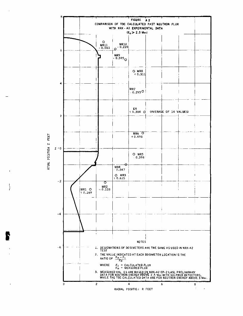
" - " ^
/
(
\ \
FIGURE A 2 COMPARISON OF TDC CALCULATED FAST NEUTRON FLUX
WITH NRX-A2 EXPERIMENTAL DATA ( E „ > 2.5 Mev)
J /
MRl O + 0.169
[ ^
1
2
3
0 MRU
- 0 . 0 6 1
y
O
MR2 V 0 . 1 2 8
MRIO Q - 0 . 2 2 0
MR9 - 0 . 5 9 5 o
Q MR4 "^
^ 0.547
O MR3 ^ 0.615
O MRS ^ 0 .311
MR7 . O.295O
ER •* 0.384 0
MR6 0 + 0.498
0 MR5 -> 0.598
NOTES
(AVERAG
1
E OF 14 VALUES) 1
r
1 1
'
. UtilGNATIONb 01- DOblMtTERb ARE THE SAME AS USED IN NRX-A2 TEST
. THE VALUE INDICATED AT EACH DOSIMETER LOCATION IS THE RATin DP ^m - Fc
l-m WHERE
. MEASURE DATA FO WHILE Th
Fc = CAI Fm = ME
DVAL ES; R NEUTRON E TDC CAL(
.CULATEDF ASUREDFLU
HRE BASED C ENERGY ABO :ULATED DA
LUX X
N NRX-A2 E VE 2.5 Mev TA ARE FOR
P-2 LASL PRELIMINARY WITH SULPHUR DETECT NEUTRON ENERGY ABO)
t
ORS, ^E3 Mev.
RADIAL POSITIO.i R FEET
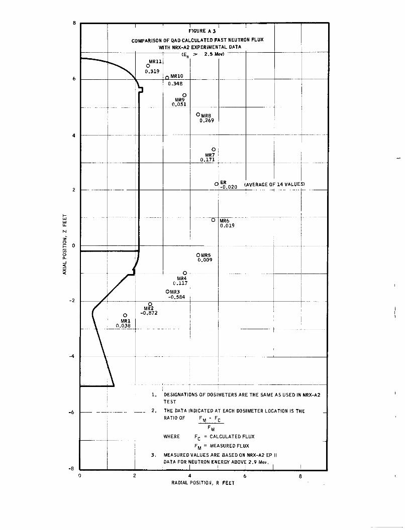
/
(
\
^
^ ^ ^ 1 — 1 FIGURE A 3
COMPARISON OF QAD CALCULATED FAST NEUTRON FLUX
WITH NRX-A2 EXPERIMENTAL DATA
J /
O MRl
0.038
i 1
1
1
MRU O 0.319
^
O MR2
-0 .872
1 .
2 .
3 .
Q M R I O
0.348
O MR9
0 .051
Q
MR4 0.117
0MR3 -0.584
DESIGNATK
TEST
THE DATA 1
> 2.5 M
O M R 8 0.269
O MR7
0 .171
O
O
OMR5 0.009
)NS OF DOSI
NDICATED A
ev)
-0 .020 (AVERAGE OF 14 VALUES)
MR6 0.019
METERS AR
T EACH DOS
E THE SAME AS USED IN NRX-A2
METFR 1 nr.ATinN !«; THF
RATIO OF Fj^ - Fj.
^M
WHERE Fp = CALCULATED FLUX
MEASURED
DATA FOR ^
F M = ME/
VALUES ARE
EUTRON EN
ASUREDFLU
: BASED ON
ERGY ABOVE
X
NRX-A2 EP
2.9 Mev.
1
1
0 2 4 6 8 RADIAL POSITION, R FEET
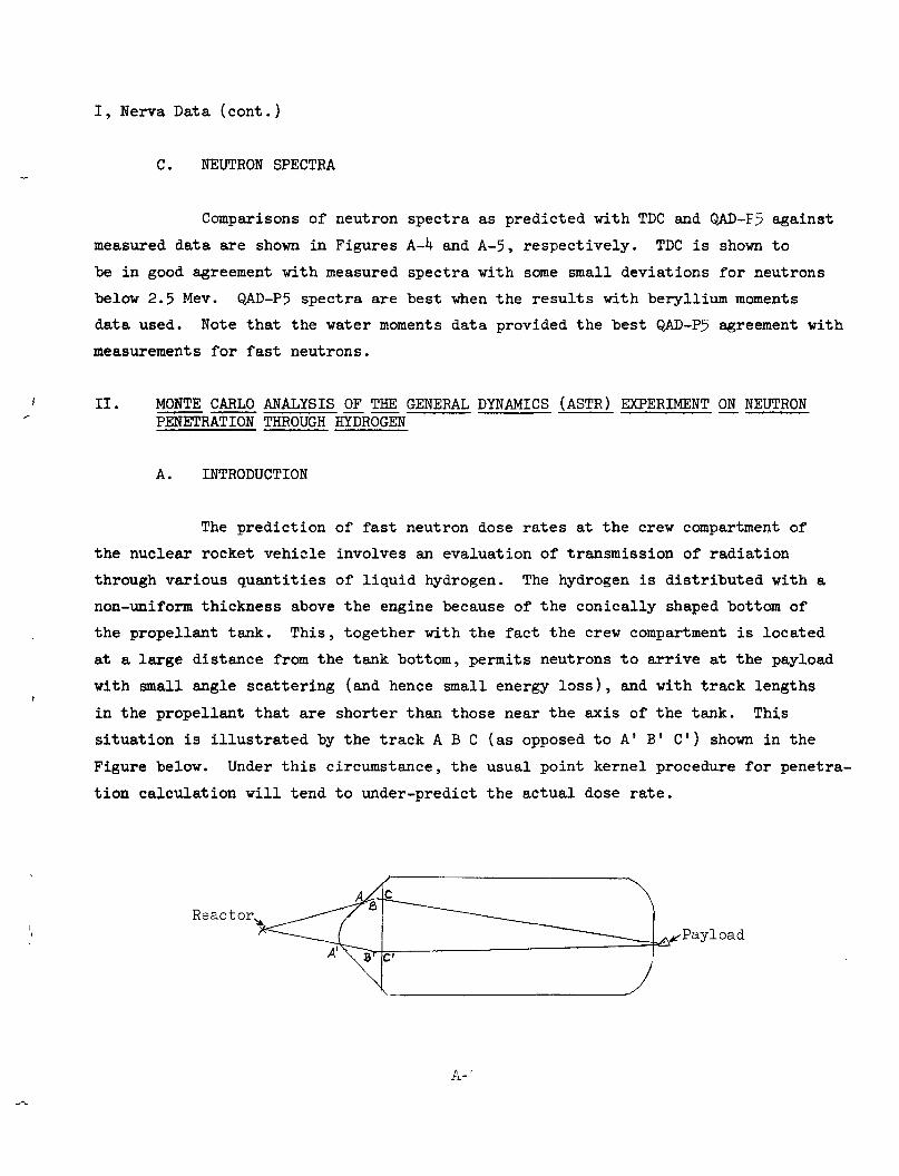
I, Nerva Data (cont.)
C. NEUTRON SPECTRA
Comparisons of neutron spectra as predicted with TDC and QAD-F5 against
measured data are shown in Figures A-k and A-5, respectively. TDC is shown to
be in good agreement with measured spectra with some small deviations for neutrons
below 2.5 Mev. QAD-P5 spectra are best when the results with beryllixim moments
data used. Note that the water moments data provided the best QAD-P5 agreement with
measurements for fast neutrons.
II. MONTE CARLO ANALYSIS OF TIffi GENERAL DYNAMICS (ASTR) EXPERIMENT ON NEUTRON PENETRATION THROUGH HYDROGEN
A. INTRODUCTION
The prediction of fast neutron dose rates at the crew compartment of
the nuclear rocket vehicle involves an evaluation of transmission of radiation
through various quantities of liquid hydrogen. The hydrogen is distributed with a
non-uniform thickness above the engine because of the conically shaped bottom of
the propellant tank. This, together with the fact the crew compartment is located
at a laxge distaJice from the tank bottom, permits neutrons to arrive at the payload
with small angle scattering (and hence small energy loss), and with track lengths
in the propellant that are shorter than those near the axis of the tank. This
situation is illustrated by the track A B C (as opposed to A' B' C ) shown in the
Figvire below. Under this circumstance, the usual point kernel procedure for penetra
tion calctilation will tend to under-predict the actual dose rate.
Reactor, Payload
A~'
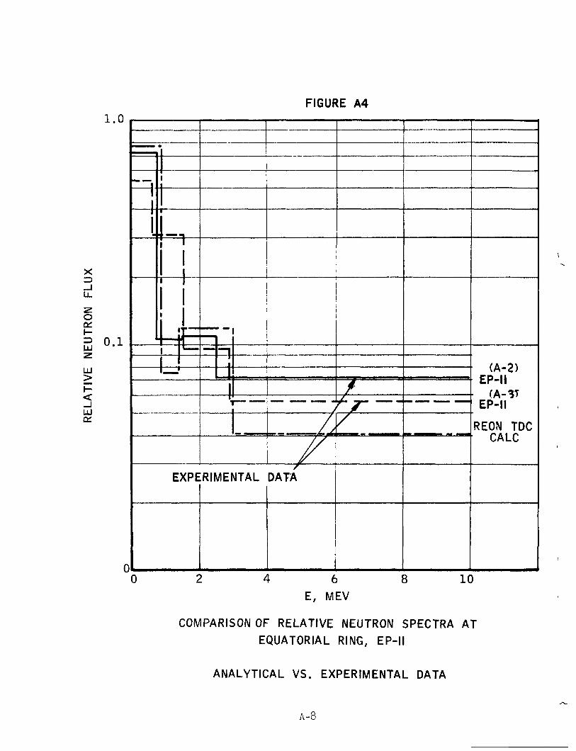
FIGURE A4
1 r~ :
r"
*
j
1
4 •"•"! 1 T
1 1 1
1 1
1
r " L_
I—,'
EXPE
•
0
—
• - |
n 1 1 _ L 1 T ~
RIMENTAL
> L
J
/ /
/
DATA
\ 6
/
^z- ' /
1
— — — ^ —
3 1(
(A-2) EP-II
• (A-3T EP-II
REON TDC CALC
)
E, MEV
COMPARISON OF RELATIVE NEUTRON SPECTRA AT EQUATORIAL RING, EP-II
ANALYTICAL VS. EXPERIMENTAL DATA
A-8
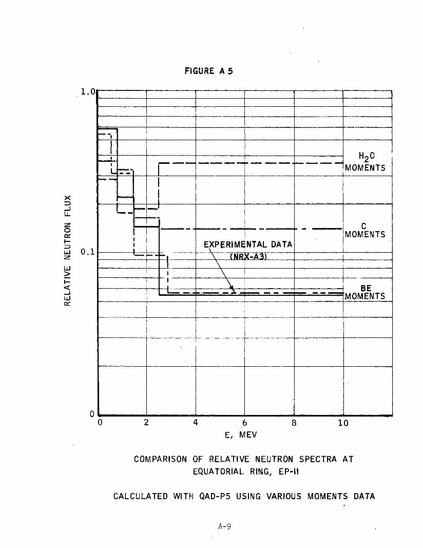
FIGURE A 5
— -
1
1
L 3 ^ -
.. ' —
tm^^m
— - —
1 1 1
i - i - ^ - j
• • •• ' • - ]
EXPERIME
\ (NR
\
\
..
NTAL DATA
<-A3)
- "
H2O MOMENTS
C MOMENTS
BE MOMENTS
0 6 E, MEV
8 10
COMPARISON OF RELATIVE NEUTRON SPECTRA AT EQUATORIAL RING, EP-II
CALCULATED WITH QAD-P5 USING VARIOUS MOMENTS DATA
A-9
II, A, Introduction (cont.)
An alternative to the point kernel method for the solution of the above
neutron transmission problem is the Monte Csurlo procedure. To provide guides helpful
in an efficient application of the Monte Carlo method, a limited ansJ-ysis was con-Al ducted of a General Dynamics experiment on neutron penetration through liquid
hydrogen. In this analysis the leakage spectrvim of the ASTR (Aerospace Shield
Test Reactor) was assumed as a source and an attempt was made theoretically to
reproduce the experimental fl\ix attenuation in hydrogen of neutrons with energies
greater than 2.9 Mev. The basic calculations were performed with the General Electric A2
Flexible Monte Carlo Code - Neutron, FMC-N.
B. ANALYSIS
1. Preliminary Calculations
Before any analysis of the experimental results were begiin, calcula
tions were performed with FMC-N to provide a test of the "exponential transformation"
as a variance reduction scheme for deep penetration calculations. In this technique,
variance is reduced by a more frequent sampling of the deep penetration event by
use of input parameters which adjust cross sections. The bias introduced is removed
by a simple deterministic correction, given by sin exponential factor. An attempt
to solve these transmission problems by using a straight Monte Carlo analogue with
out resort to any variance reducing scheme would result in a prohibitive expenditure
of computer time.
The conditions for these initial calculations were identical with
those assumed in a detailed study conducted by Burrell (Reference A3). The
geometry consisted of a cylindrical slab of liquid hydrogen (density 0.07 gm/cm )
whose diameter-to-thickness ratio is large. A monodirectional beam of 8 Mev neutrons
are directed into the slab ajQd the current of neutrons with energies greater than
0.01 Mev are counted. The hydrogen cross sections were obtained from BNL-325> and
were chosen at a sufficient number of points, so that straight line segments connect
ing adjacent values yield a close representation of the actual cross section over
the energy range of interest.
A-10
II, B, Analysis (cont.)
Slab thicknesses of 83.96 and I6T.92 cm were considered. The
results, represented as buildup factors (ratio of uncollided plus scattered current
to uncollided current), axe compaxed with those of Burrell below.
Neutron Buildup Factor
Thickness, cm Present Calculation Burrell's Result
83.96 U.3 h.k
167.92 6.5 6.6
The agreement is good, giving confidence in the exponential transformation option
of FMC as a scheme for calculating deep penetrations.
^' Monte Caxlo Mockup of the General Dynamics Experiment
The General Dynamics experiment "was designed to simulate the
radiation source and liquid-hydrogen propellant-tank of a typical nuclear rocket
system design." The experimental arrangement consisted of the ASTR (Aerospace
Shield Test Reactor) and a 125-gal hydrogen dewar, positioned in the ASTR tank
as shown to approximate scale in Figure A-6. For greater details, one is referred
to References Al and A5. The dewar, placed within a liner tank, is positioned so
that it sits directly above the reactor. Neutron flux measurements were taken
with foils at various points within the hydrogen tank.
In the present calculations the configuration was mocked up as
shown in Figure A-7. Only one medium of interaction is assumed, namely liquid
hydrogen. Several small detector regions axe defined in the system which enable
the evaluation of flxxx from the track length tally of the FMC-N program. Actually,
33 regions and 25 surfaces were defined in the calculation, but for the sake of
clarity all axe not shown in Figure A-7. The reactor is approximated by a point
isotropic source located 6.73 in. from the center of the core and in the direction
of the hydrogen tank. The location of this "effective" point source is taken to
A-11
FIGURE A 6
EXPERIMENTAL APgANGEMENT
45"
2 2 5 "
z. LIQUID LEVEL
•34"-
•VL
VOID
44"
•LHj DEWAi?
•LINEP TANK.
WATEe -
PKE.SSUBE VfcSStL
• J '
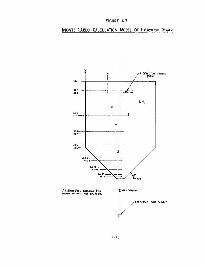
FIGURE A 7
MoNTE CARLO CALCULATION MODEL OF HYDROGEN QBMA^
A DETECTOR REGIOKJ (VOIB)
All dim«n»ion& hcafturod front soure*. or axi» 4nd ar*. in em.
^', OF SYMMITRY
•EFFECTIVE PO(WT SOURCE
A-13
II, B, Analysis (cont.)
be that point from which an inverse square relation maintains in describing attenua-A5 tion of neutron flux in air. Using the data on ASTR radiation map in air, it was
found that the above location of the "effective" point source yields an inverse
square attenuation that equaled the experimental attenuation to within +3% between
25 and 65 inches from the core center. It should be pointed out that an "effective"
soiirce as is defined here is not a unique method for representing the source. A
selection from various types of surface sources with different spacial and angular
distribution can be made but the effort required to determine whether a more satis
factory choice is possible is outside the scope of this study.
A total of 11,000 neutron histories were studied with the source
neutrons distributed as follows:
a. Between 0° - 9° (measured from the reactor-tank axis),
1000 neutrons each at k, 6, 7.25 and 8.5 Mev.
b. Between 9° - 19°, 1000 neutrons at same energies.
c. Between 19° - 26°, 8OO neutrons at U, 7.25 and 8.5 Mev,
600 neutrons at 6 Mev.
The maximum angle of 26° corresponds to the angle subtended by the
tank used in the experiment.
The results of the calculations, normalized to a source strength
of 2 neutrons/sec, are summarized in Figure A-8. Since the detector has a threshold
of 2.9 Mev, the flux values at this energy are readily obtained by the exponential
and inverse distance-square law. Except for the three top Monte Carlo values at
7.25 Mev, the results fall essentially on smooth curves.
A ik
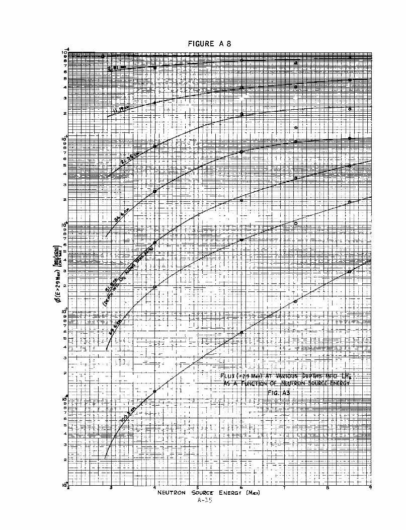
FIGURE A 8
II, B, Analysis (cont.)
The same results are presented In Figure A-9 but now axe weighted A5
according to the ASTR leakage spectrum. It Is noticed that although the high
energy contribution is depressed somewhat there is still a significant contribution
from source energies greater than 9 Mev for penetrations greater theui euround 60 cm
of hydrogen. At 100.2 cm of hydrogen, it is estimated that the Integral flux above
9 Mev is U0-50Jt of the flux from 2.9 to 9 Mev.
The flux of neutrons between 2.9 and 9 Mev has been obtained by
ntunerically integrating curves of Figure A-9. The variation of this flux with
distance in hydrogen Is compared with that of experiment in Figure A-IO. Again,
it is pointed out that the Intent here is to compare penetration within hydrogen,
hence the normalization indicated in Figure A-IO.
C. DISCUSSION OF RESULTS
Comparison of the final calculated results with the experimental data
raises a number of questions. The major sources of the discrepancies, however,
are not obscure. The cause of the difference near the origin is mostly caused
by the shadowing effect of piping below the tank bottom, which Is not accounted
in the calculation. If one assumes the shielding effect of the piping to be
approximated by that of a small-diameter, stainless steel disc of 0.32 In. thickness
and apply a correction based on this assumption, the difference near the origin would
be only about 23% relative to the experimental point. One of the sources of discrep
ancy at the large thickness is evident from the results of Flgixre A-9; there Is a
sizeable contribution to flux due to neutrons above 9 Mev which are not Included in
these calculations. If one applies a factor of "^ 1.5 (an estimate of the correction
for the contribution above 9 Mev) to the calculated value at 100 cm, there Is improve
ment but still a factor of two discrepancies yet to be explained. The causes of the
remaining difference are probably due to (a) neutrons streaming along the void spaces
surrounding the hydrogen, and then being deflected laterally into the tank, thus
enhancing the experimental flvix at the detectors located deep within the hydrogen,
and (b) the assumption of a point isotropic source in the calctilatlon, when in reality
the leakage neutrons are emitted with a preferential forward direction.
A-l6
i r f 9 8 •7
6
5
3
vi 9 8 7 e 5
4
3
S 9
- J
Ll- 3
UJ
5 ' UJ
10 9 8
5
2
1 9 8
A
3
2
i
-
=
r
'A ^—
1
~ ~ —
^
-a
^ E
1 z:
—
1
-Z
1
=
— -
>
^
1
_
1
1
1
1
i d F":
1
— —
1
r : 1—
i
— 1— 1—
1 r r =:3
B t "
-: ^
1 1
^
-
p--
h
—
i
z:.
1
E
—
1
=
E
1
i
1
1
-: ^ ^ '-
^
1 _—
1
E
-
= 1
-—
1
E
E =
1
^ ! '—
1
Ef
:H
- i
;; =
1
=
^
i
m
i
E
—
1
§
1—
1
-- -TJ
:-r
;;-li-
;:
1
— — •
1
1
p —
1
E t=;
~ ^
=? -^
1
1 = i
1
1 E P
!
^
^ ;-W
i
= —'
1 i
a u_
^
^ l 3 1 —
=
F --k
Ig fx j ^ 1 ^
-
~
L-
1
=,
ilr
—
1 1
:d
1 E
—
: z
1—
i :
Z l
i
1
—
:= ^ -
1 E
^
1
n
1
ir
E
1
;
1
b. ^
1 ^
1
~
E
...
3
1 is -—
1:
--—
* t
^
?? >/-
1^1
r--;t
y ^ p^
E ^
~ :
- -
1 --:!
!:-
Er
..._
>
n
i §
==: —'
J i
I I
- -—
i»
','
i |
11
1
1
—
-
a
=
•f r-*
1
1 •
1 1^1 /f-=3-J
"" \-S
^A
^ E
~~
4-
il r i -
_ r_
11
= =
-g
?:
£
E
=
b
i
^
1
-~
::
1 1;
E
pz
->
::r
—
1 = a s=
~t ^
E
~
—
i
~ t -
1
i - t -H
t
^
£
~
-"
1
i 1
E
1 -
^
^ -IT
::
i
= E
U H
"+ - ;
1
rr 1 —
s t ;
•
1
1 ~ '
V
1 — E]
5^
a
i i
E
1
% „ -
^
^
B
1 1
E t ,
5
1
E
i
E
^ ,-r-|--
^
-
:: '—1
l "
/
—
1
1 3 --E ^A
/
p j ? ;
t - - :
^
a
1 ~
— 1
1 —
i
1 —
-
—
E;
"
fca
1 3 ,-/
^
—,
E
E?
1
i
t-H
E 1
1
1
-
^
" E^fe
^^fj
E
E
-^
1 E;
=
E
1 —
.:; I -
E;
E
e
E
i
*
^
• ^
"
^ „ -
S
E
-
i -
^
~ i b
h^ta
-1
^
h
l i i
"" —
t
& -rr
-'-'-=-E
E
::.
1
E
-
E
E
—
t
-
-1 -E"-
i:
::
?
7^
~
r
:-Er ^ t =
i ~
—
^
d;" i T
E
^
i —
B «
_": —
^
= —
=:
1 E
-
i g
i
-
=
— — -^
i
^ —
^
:-= ^r
Fr
;:E
i= E
~
L-
U
E-
i
E
—
1
1
-r
'F^
s
^
r r
—
^
1
1
— E
E
^
• ^
—
1 er = ^-z FS
^ =
e l
j :£?]
1
—
^
I.-
^
^
r~
—
"
FIGURE
=
=
-§
s
^
—
-&
...1.1
pi h ^
h E ^
E
i EE
^ _-1
_
=
^ —
1
3 3 l i z
E"r
EE
£ -
^
~
~ I
i
!-:_ E
EE
E
—
:: ^
r^
^
~
-
1
^ E E
-:= E
E
E
—1
=
—
1
E-— f —
f
=p-~ • - -
^-:i
K
— •
=
E:
'~ —
1
r =
^ ^ f.3F?
-^^ . a---
E
"z:
—
p — E-
" ?=
i
E
—
-
E
~
1 —
i ^ I Z
1:
1
E
—
-
E
~
-Sd
h_
E
1—
1
-
i
E
1=--
~
r
E
E
1
—
«
^^
= =
- -~-
l i
S 5 r j :
Ef:
1
f
^^
E E
^ = = ; E
= E
^l
E =
z I
1 —
^
:^"
i i Ef
1
i s
= ~
± E
-M
i i
=1
-—
' E
i i
•
- —
11
= =: 3 ^ ^
^ ^ =
E — —.
^
i
t r
— E
i ^
13
— =:
4Ffe == ^
==
i i !
T-:-
1 = a
—
= =
E
~
—
1
A9
^
—
•
»
1
3 -
1
1
^
E =E
E
^
m. • - ^
^
i 1 7^ >
— '"
1
-
^
r^,z
1 ^
1
— - -E
[
~ —
1
-: ^ FS
= =
1 ~
^
^
I -
~1
=
1 X
—' —
1
1 E
E
— — :-
r-
r
^
; E
;;
~
—
^
5
---
-;
1 1
:- —
E
1 ^
^ r
f—•
- ~ i
5
"
-
5
=f
i
—
E
1
m
z -F=
s
E
^
~
~ H
r?
-^ ^
r
-
^ H
m w z
~ '
k
H --
-
1
±3
5< H^
" • • _ ,
E
—1
E
1
^
-
1
-— --= t^
E
^
1
E
-^-
J —
F U
f=
in N
—
<
1
^ S -
="j
-
^
1
i
i
-^
E
§
i • t
-.: —
"
-
~ -
~
1 E
1
^
=
s 2
-Z :
1 d
-
-
1
— 3
^
i
^
^
• • 1 ^ E
E
^
i
1
E
-
1
i "1
1
E
=fe — 1 — ,
.-i^ ~| '
^
3
t: ~ —
t j
1—
1
1
-
E
1
E 3
: ^ 12
-
1
„
-
T J-
^'
1
'"
1 77
'—
i =
i = =
5 ;
E :
-'
1 1=
II -z E-h - -
11
-
E = •
--
if
E E = E
= = b= E =
^ :
_._
1 -
il
_._
I i
J E
5 E -
t i
i g
1 ^
1
E
-?•
1
: r
1 =
,-
g
E
-""
S
1
1 ^ ^ i - ^
| E 1
E
--'
H
^
^
t
(
£ E
t
:^
-
^
EE
-=-1 =
E T I
;:-
T:
i l
- -
—
-
=
SI
1 =,
V ,
^
-
E
^ L; a
1
_.
1
E
E
i
_-!
1 1
-
1
=:
-^
^
S
S
z_ E
-
1
1 •
-
r^
1
—
— r f"
i
~
—
1 3
i s =
-
7
i
=
— E
^
S;
§
•Ss
p
^
• - -
i
-zr
r E
i
^
1
-
i
—
---
>
s^
i
^
i
-
-
E
\ \
—
1
E
— —
.
1
;-_
5
_. E
1
-zz
--^
=
i
=
i
=:
-—
1 EE
1
b E
^
1 — E
~
""-
1
= a
^ t z
p E
E
-
1
EE
T
"
g
E
— —
j
S
I Z
^
^
^
E
T p
^ 1
TZT
s —
1 =
Ii
\-r_z E :
E .
1?
i^
Ef
^ -
11
r t n
- — •
i ^ E
T:E
1 i —j—
P =
M I
EEE
- -
1:
i l
S I
,E •
1 =
^ I E : -
' j _ f . ' t i —
^T^E r E 3 " E r
i
E_
=
E
1
'"*"' - ,
: T L; -
^ -;-=3=
E ^
= = P T
II —!-
=:: 1 — 4 -
+
ft:
+1 \ l •
"?' " ^ ^ :
£ z~
= =
II E ! =
1 E|
E -
EE
If
: = E
1 EE
'—
a
s i
z~z
-jf-— - —
p
ii
- -^"
1 = =
^^
E
—
—
= ^
J_
E
E 4 E
i -5E_
EE -—
1 E : ^
Ij EE
i
E
— E-
—
1
1
1
— —
i
z-
-E-
-
1=
i
Er —
s !
'
a
E
-^ U-^
=
1
i
s
1
E3
5
zz —
S
Z -
= t E
^
E
=
1 E
1
E: 1 —
E
E
— — —
I
5
:.-;
- H
SI
h
3
-
1
J
^ -
E^
h E
=
1
E
i
~
-— -
M
1 1 zz
-E
^
j E
3
zz^ —'
1 _ _
—
^
=
• :
1
i —
a
E
-e
E
"
^
E
— — '
i
^
— -
1
N .
^
1
i i r
— — -
1
j s — -
1 S
—
• ^
1
—
z_
-
1
i
--
I s
~
^
_
= '—
E
^
• —
• -
7-
E
~
c
1
=
i
EE
-_
^
_ !_ ~ i _
F 1
1
pr
i
—
~
i
i
—
E
-
1
1
1 :
s
E
1
™
•5
—
1 P h£
^ --~ E
E
E
—
i
E
i
E
—
* NEUTRON SOURCE ENERGY. M«M
A-17
1 < ^ .
FIGURE A 10
" M c J* r{
1
< C
I.
Myiliiiiiiiiiiiiiiiiiiiiiiiiiiiiiiiiiiiiiiiiiiiiiiiiiiiiiiiliilii 4'} mrrrnt ffltffM^ E?i;SEEEEEEE=EEE=""=E"= =="=== ====±^^=========--A
V
\ \ \ , ^ S f _. 1 1 L J , - , . ^ . lO ^ = rT; = ^ l r « 1
'W\\ \ \ \ \\iWmM^m\mw^\ \ ^ ^ M
2 = ^ ^ ^ = - — ^ — S " S S f » l B S E « F i < ^ ^ ^ r i : ±
7 L A ^ - ^ -gS j ^e j i ^F j l - ^5 {^^^£^^5-g : tpeH l l1h iT ;a : - ^ t t€ -B-SH«or r -* ^ A I 2 9 *l E ' IK l) < "5
s ^ • \ ^ E_ ^ - v +^ - f ^ . . . - . - . . - E I "" La f- ^-. -^-. H . +- - -^ ^^ 5 9 i i * i i i i ^ i i i i i i i i i i i i | l | i i i i i i i i r t i | ^ l l l i l l l i i i i i , i i i i i i i i i i i i i i i i i
b ^ p~: „-.- - --==:-= S-?^:-—z:.-,.-p^ —(:= ^
\^^^^^^^p^^f^K^^ 3 H^B^^S^P^t j f lp f rffffM'^ r ff4l^4i4fiiffiT]^]E Mi4i4i4i4tH4tS!f n^
^L^LzIffi J MjMiilMJrjii 11J [ N^ \ \ 1 ! ] ' '
1 \ 1 1 *^ •-. ^ . X- - E i " " pf-~.~ -1^- """E-\t;| """x^j: ~'~' "^ "" " " " X ^
9 „ _„ „ _ _ _ : : „ 7- =^=. ^ S _ „ - . ..
e - -g.. .= = ^_^_ = _:_.,_=: = „.,,,==-._..^E|_ .= ..^_.^-_=._,,-.^__^ ,_J._,,_.„_.,,_..^^„ : . - : ^ ; -L j - . _ -_ ._i^^i ^ _tz. .._ i =: r ^ : .^z: 1 ^ 4 = " ' " ^ " =E T = E '
t ~T T it 11 r"E" E4^ t T tEiEi"' 1 n\ri r L r l ! M t T T TE T \\ r i ^ ^ j— . J L . > \
, ]T-E-M|:#ff^y||ffl^^ HEj ^z+- : ? - --- - - | J. - - --^5, 5, _ L
—••; f ' — - : : —— - - — - — ' — —|— - -r—• •- —' - - • —v-_^_ .\ .- — . „ _ _ 1
- p - ~ = =XjC^^^..,,,,E^.4EE=-=:"-^-^-^E^^:__^__--_-_^ = __ = . ^ _=z==r___ _ ._ = —-=X: . :^ - : iF- = 4:r:^E^^ErE _j E_ -E-^ \7.: = = zz^^^ = -^^^ = -^-^ — ^—~~~^~
. + 4 f - 1 __ ^ . _ , ._ J^^ — i— —~ — ^ 1 '• \ -| j - . - . . . ^ - . . . _. - j . . . . — _. . >,. ______„
1 ^
-i -^-^ "} \ -' \ j j I 1 j j 1
r/x ,.„ 1 .. 1 i ! . 1 1 , . 1 . 1 1 1 1 20 40 bo BO
CENTER LINE DISTANCE, (cm) A-18
REFERENCES - APPENDIX
1 Nuclear Radiation Heating in Liquid Hydrogen, W. A. Hehs, et al., General Dynamics/Fort Worth, Report FZK-186-1, June I96k.
2 Analytical and Preliminary Design Studies of Nuclear Rocket Propulsion Systems, Aerojet Report Ho. 1999» June 1961
3 Nuclear Radiation Transfer and Heat Deposition. M. 0. Burrell, NASA TND-1115, August 1962.
k Neutron Cross Sections, D. J. Hughes and R. B. Schwartz, Brookhaven National Laboratory, Report BNL-325, July 1958.
5 Spatial and Energy Distribution of the Nuclear Field in the ASTR Radiation Effects Test Cell. General Dynamics/Fort Worth. FZK-169, August 1963.
A-19
Recommended