Sequential Circuits
Chapter 4S. Dandamudi
2003To be used with S. Dandamudi, “Fundamentals of Computer Organization and Design,” Springer, 2003.
S. Dandamudi Chapter 4: Page 2
Outline
• Introduction• Clock signal
∗ Propagation delay
• Latches∗ SR latch∗ Clocked SR latch∗ D latch∗ JK latch
• Flip flops∗ D flip flop∗ JK flip flop
• Example chips• Example sequential circuits
∗ Shift registers∗ Counters
• Sequential circuit design∗ Simple design examples
» Binary counter» General counter
∗ General design process» Examples
– Even-parity checker– Pattern recognition
2003To be used with S. Dandamudi, “Fundamentals of Computer Organization and Design,” Springer, 2003.
S. Dandamudi Chapter 4: Page 3
Introduction
• Output depends on current as well as past inputs∗ Depends on the history∗ Have “memory” property
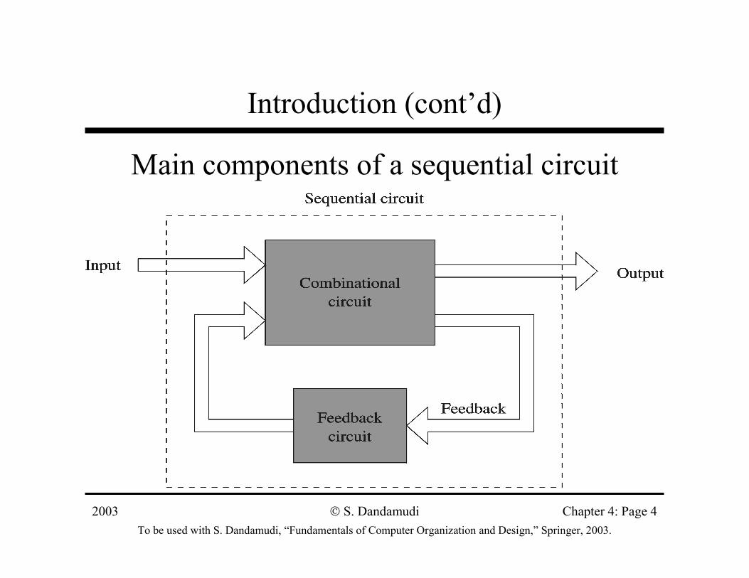
• Sequential circuit consists of » Combinational circuit» Feedback circuit
∗ Past input is encoded into a set of state variables» Uses feedback (to feed the state variables)
– Simple feedback– Uses flip flops
2003To be used with S. Dandamudi, “Fundamentals of Computer Organization and Design,” Springer, 2003.
S. Dandamudi Chapter 4: Page 4
Introduction (cont’d)
Main components of a sequential circuit
2003To be used with S. Dandamudi, “Fundamentals of Computer Organization and Design,” Springer, 2003.
S. Dandamudi Chapter 4: Page 5
Introduction (cont’d)
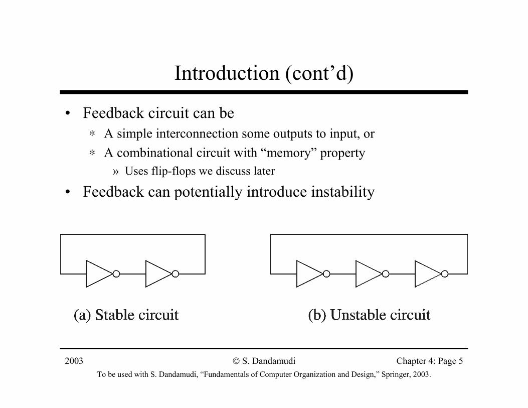
• Feedback circuit can be∗ A simple interconnection some outputs to input, or∗ A combinational circuit with “memory” property
» Uses flip-flops we discuss later
• Feedback can potentially introduce instability
2003To be used with S. Dandamudi, “Fundamentals of Computer Organization and Design,” Springer, 2003.
S. Dandamudi Chapter 4: Page 6
Clock Signal
• Digital circuits can be operated in∗ Asynchronous mode
» Circuits operate independently– Several disadvantages
∗ Synchronous mode» Circuits operate in lock-step» A common clock signal drives the circuits
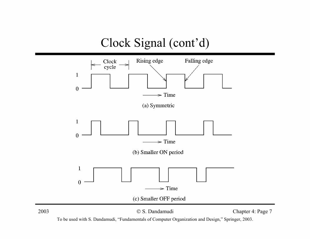
• Clock signal∗ A sequence of 1s and 0s (ON and OFF periods)∗ Need not be symmetric
2003To be used with S. Dandamudi, “Fundamentals of Computer Organization and Design,” Springer, 2003.
S. Dandamudi Chapter 4: Page 7
Clock Signal (cont’d)
2003To be used with S. Dandamudi, “Fundamentals of Computer Organization and Design,” Springer, 2003.
S. Dandamudi Chapter 4: Page 8
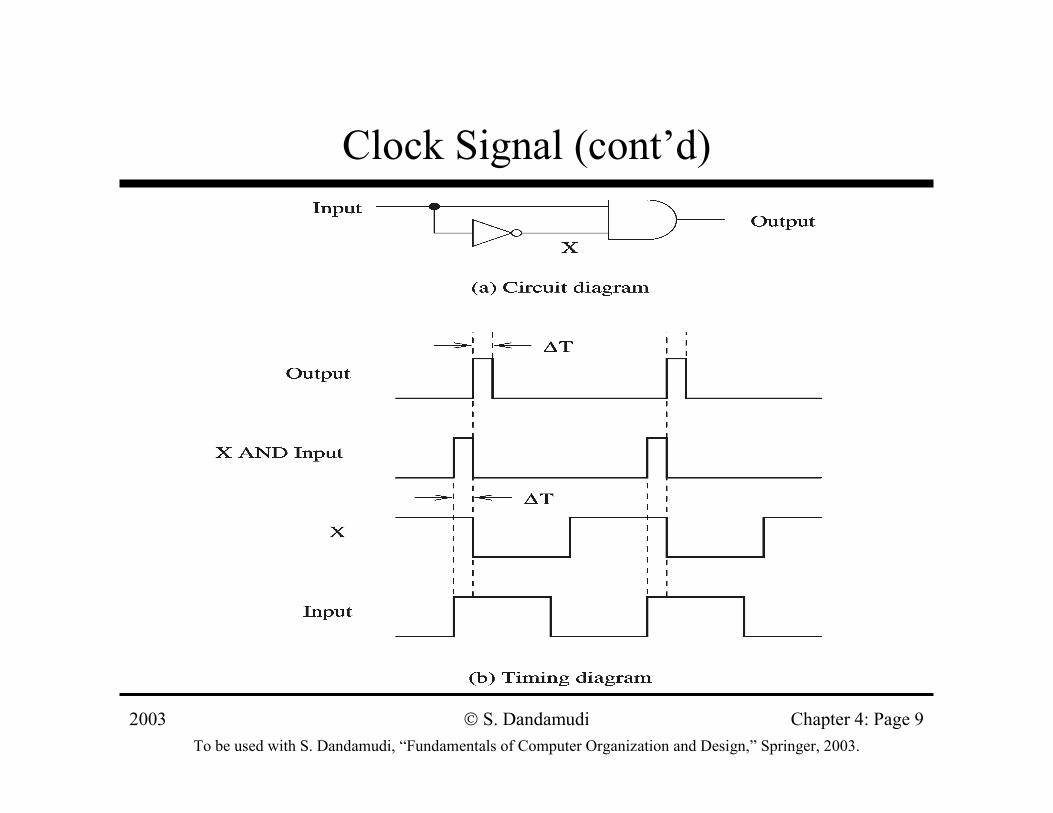
Clock Signal (cont’d)
• Clock serves two distinct purposes∗ Synchronization point
» Start of a cycle» End of a cycle» Intermediate point at which the clock signal changes levels
∗ Timing information» Clock period, ON, and OFF periods
• Propagation delay∗ Time required for the output to react to changes in the
inputs
2003To be used with S. Dandamudi, “Fundamentals of Computer Organization and Design,” Springer, 2003.
S. Dandamudi Chapter 4: Page 9
Clock Signal (cont’d)
2003To be used with S. Dandamudi, “Fundamentals of Computer Organization and Design,” Springer, 2003.
S. Dandamudi Chapter 4: Page 10
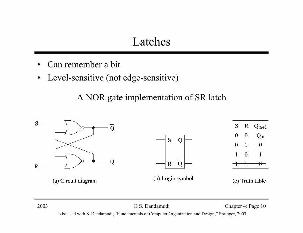
Latches
• Can remember a bit• Level-sensitive (not edge-sensitive)
A NOR gate implementation of SR latch
2003To be used with S. Dandamudi, “Fundamentals of Computer Organization and Design,” Springer, 2003.
S. Dandamudi Chapter 4: Page 11
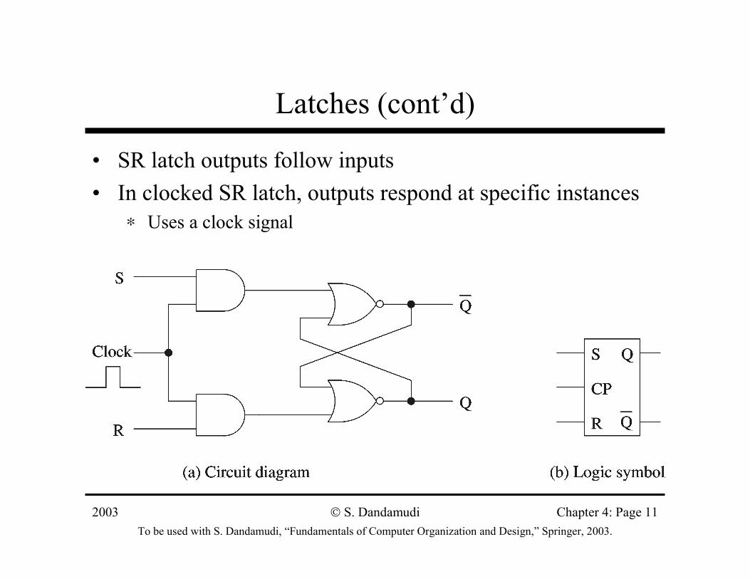
Latches (cont’d)
• SR latch outputs follow inputs• In clocked SR latch, outputs respond at specific instances
∗ Uses a clock signal
2003To be used with S. Dandamudi, “Fundamentals of Computer Organization and Design,” Springer, 2003.
S. Dandamudi Chapter 4: Page 12
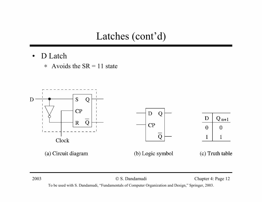
Latches (cont’d)
• D Latch∗ Avoids the SR = 11 state

2003To be used with S. Dandamudi, “Fundamentals of Computer Organization and Design,” Springer, 2003.
S. Dandamudi Chapter 4: Page 13
Flip-Flops
• Edge-sensitive devices∗ Changes occur either at positive or negative edges
Positive edge-triggered D flip-flop
2003To be used with S. Dandamudi, “Fundamentals of Computer Organization and Design,” Springer, 2003.
S. Dandamudi Chapter 4: Page 14
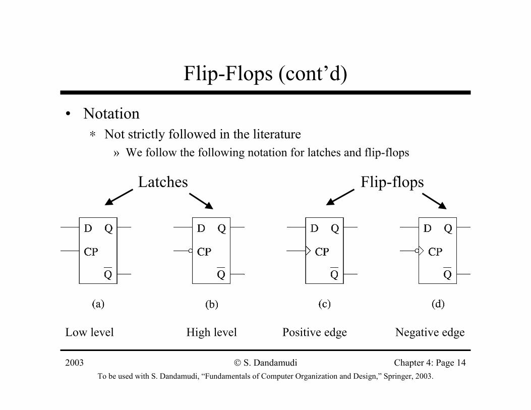
Flip-Flops (cont’d)
• Notation∗ Not strictly followed in the literature
» We follow the following notation for latches and flip-flops
Low level High level Positive edge Negative edge
Latches Flip-flops
2003To be used with S. Dandamudi, “Fundamentals of Computer Organization and Design,” Springer, 2003.
S. Dandamudi Chapter 4: Page 15
Flip-Flops (cont’d)
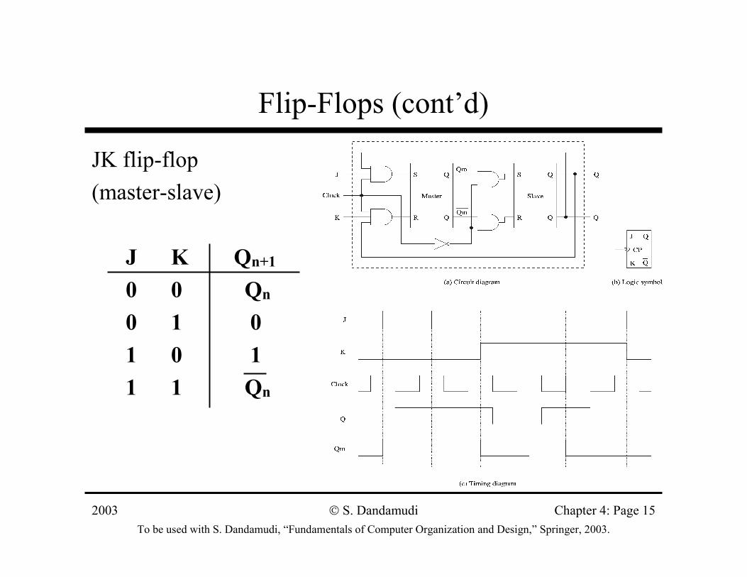
JK flip-flop (master-slave)
J K Qn+1
0 0 Qn
0 1 01 0 11 1 Qn
2003To be used with S. Dandamudi, “Fundamentals of Computer Organization and Design,” Springer, 2003.
S. Dandamudi Chapter 4: Page 16
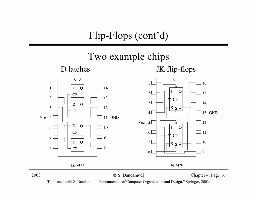
Flip-Flops (cont’d)
Two example chipsD latches JK flip-flops
2003To be used with S. Dandamudi, “Fundamentals of Computer Organization and Design,” Springer, 2003.
S. Dandamudi Chapter 4: Page 17
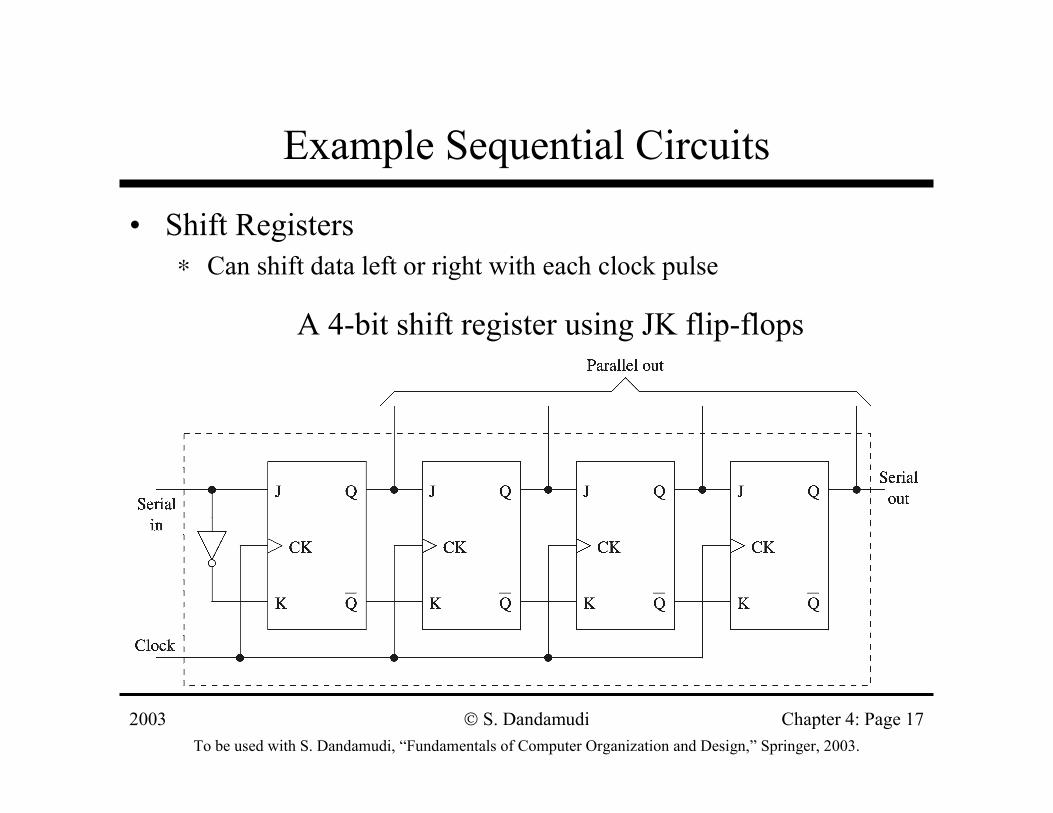
Example Sequential Circuits
• Shift Registers∗ Can shift data left or right with each clock pulse
A 4-bit shift register using JK flip-flops
2003To be used with S. Dandamudi, “Fundamentals of Computer Organization and Design,” Springer, 2003.
S. Dandamudi Chapter 4: Page 18
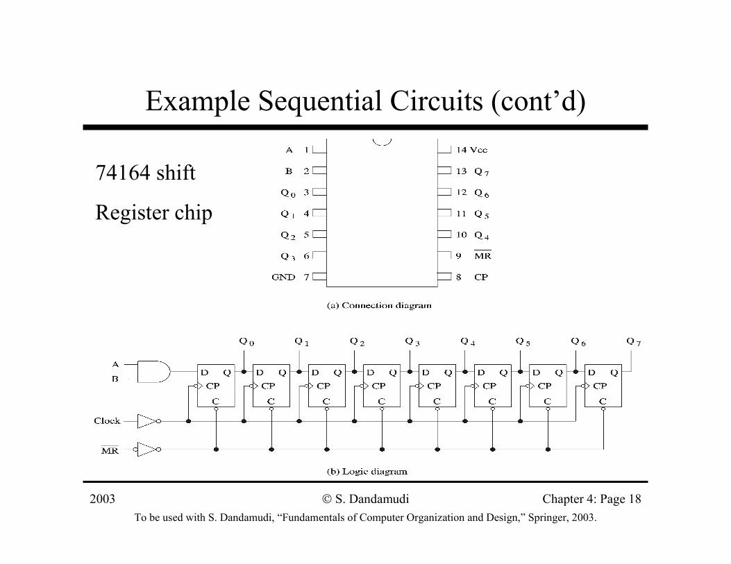
Example Sequential Circuits (cont’d)
74164 shift
Register chip
2003To be used with S. Dandamudi, “Fundamentals of Computer Organization and Design,” Springer, 2003.
S. Dandamudi Chapter 4: Page 19
Example Sequential Circuits (cont’d)
• Counters∗ Easy to build using JK flip-flops
» Use the JK = 11 to toggle∗ Binary counters
» Simple design– B bits can count from 0 to 2B−−−−1
» Ripple counter– Increased delay as in ripple-carry adders– Delay proportional to the number of bits
» Synchronous counters– Output changes more or less simultaneously– Additional cost/complexity
2003To be used with S. Dandamudi, “Fundamentals of Computer Organization and Design,” Springer, 2003.
S. Dandamudi Chapter 4: Page 20
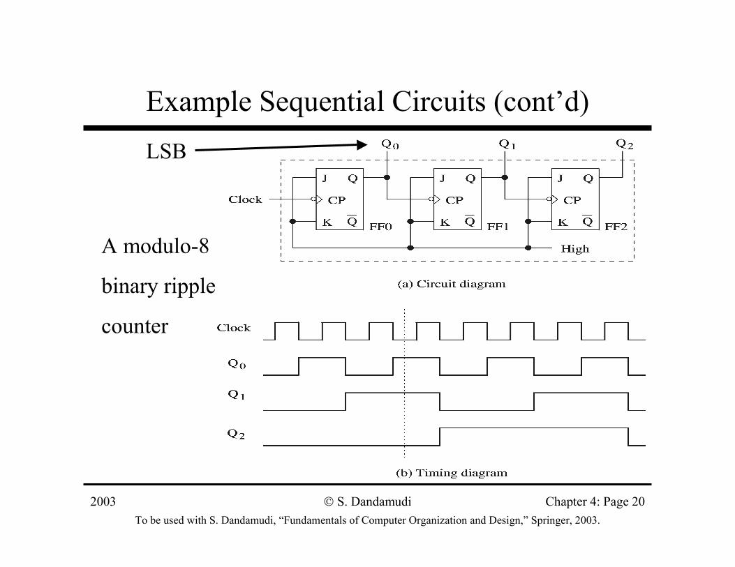
Example Sequential Circuits (cont’d)
A modulo-8
binary ripple
counter
LSB
2003To be used with S. Dandamudi, “Fundamentals of Computer Organization and Design,” Springer, 2003.
S. Dandamudi Chapter 4: Page 21
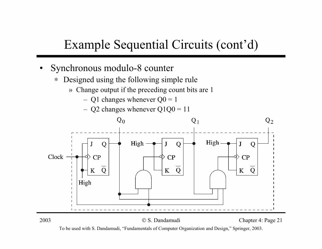
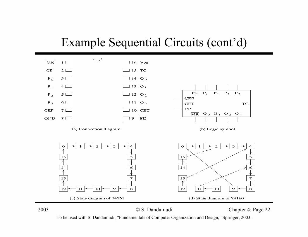
Example Sequential Circuits (cont’d)
• Synchronous modulo-8 counter∗ Designed using the following simple rule
» Change output if the preceding count bits are 1– Q1 changes whenever Q0 = 1– Q2 changes whenever Q1Q0 = 11
2003To be used with S. Dandamudi, “Fundamentals of Computer Organization and Design,” Springer, 2003.
S. Dandamudi Chapter 4: Page 22
Example Sequential Circuits (cont’d)
2003To be used with S. Dandamudi, “Fundamentals of Computer Organization and Design,” Springer, 2003.
S. Dandamudi Chapter 4: Page 23
Example Sequential Circuits (cont’d)
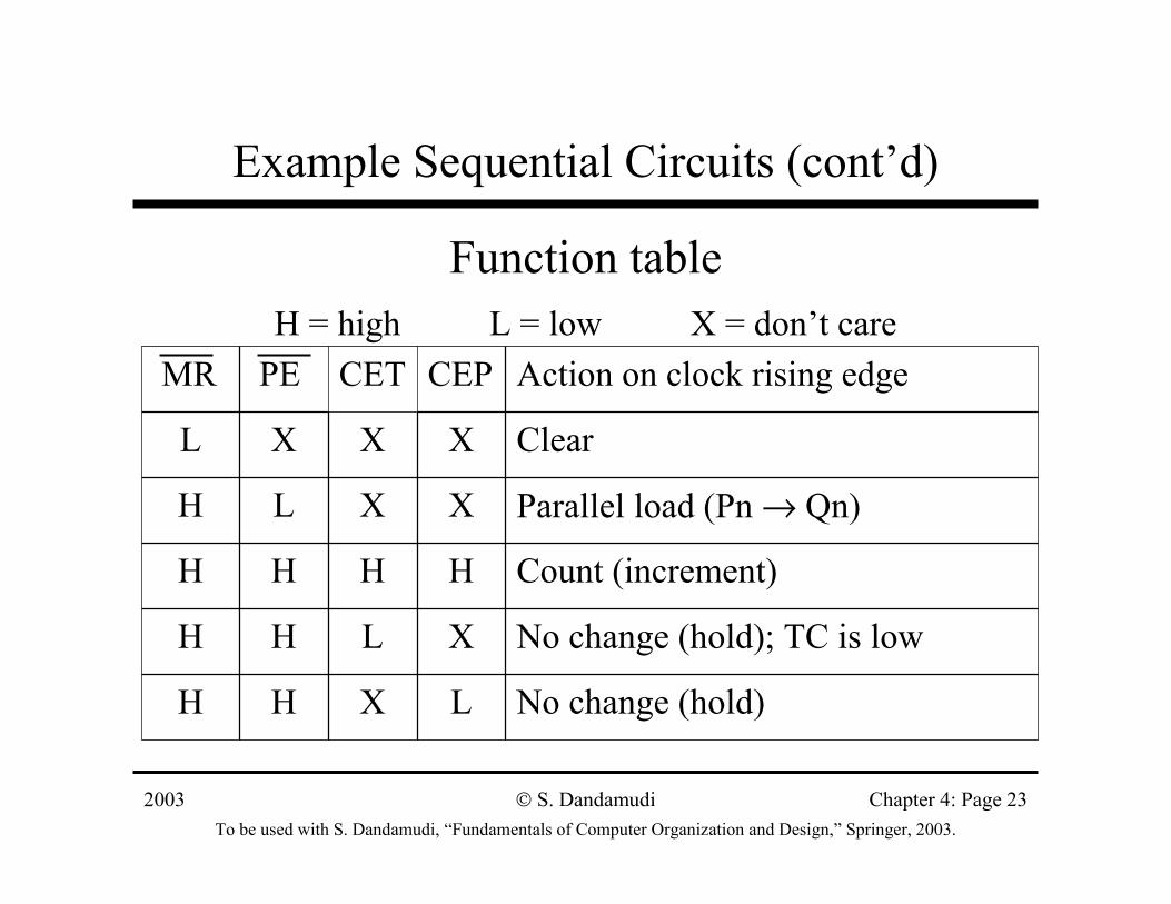
Function tableH = high L = low X = don’t care
No change (hold)LXHH
No change (hold); TC is lowXLHH
Count (increment)HHHH
Parallel load (Pn → Qn)XXLH
ClearXXXL
Action on clock rising edgeCEPCETPEMR
2003To be used with S. Dandamudi, “Fundamentals of Computer Organization and Design,” Springer, 2003.
S. Dandamudi Chapter 4: Page 24
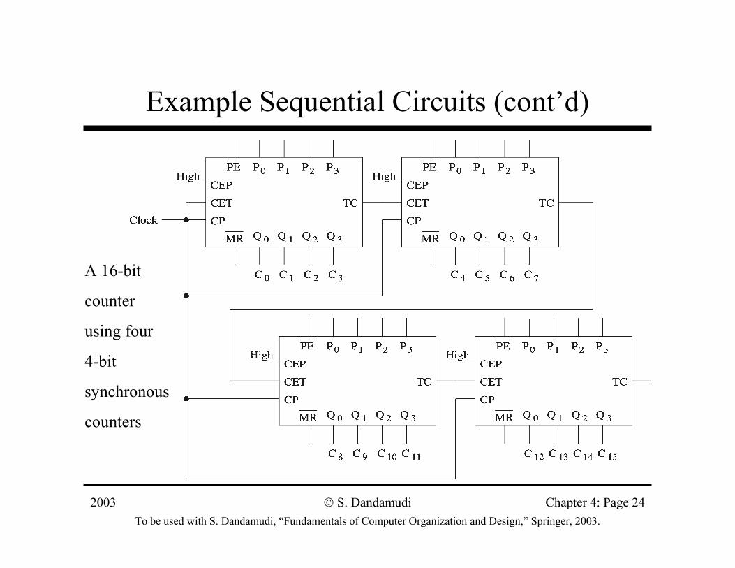
Example Sequential Circuits (cont’d)
A 16-bit
counter
using four
4-bit
synchronous
counters
2003To be used with S. Dandamudi, “Fundamentals of Computer Organization and Design,” Springer, 2003.
S. Dandamudi Chapter 4: Page 25
Sequential Circuit Design
• Sequential circuit consists of ∗ A combinational circuit that produces output∗ A feedback circuit
» We use JK flip-flops for the feedback circuit
• Simple counter examples using JK flip-flops∗ Provides alternative counter designs∗ We know the output
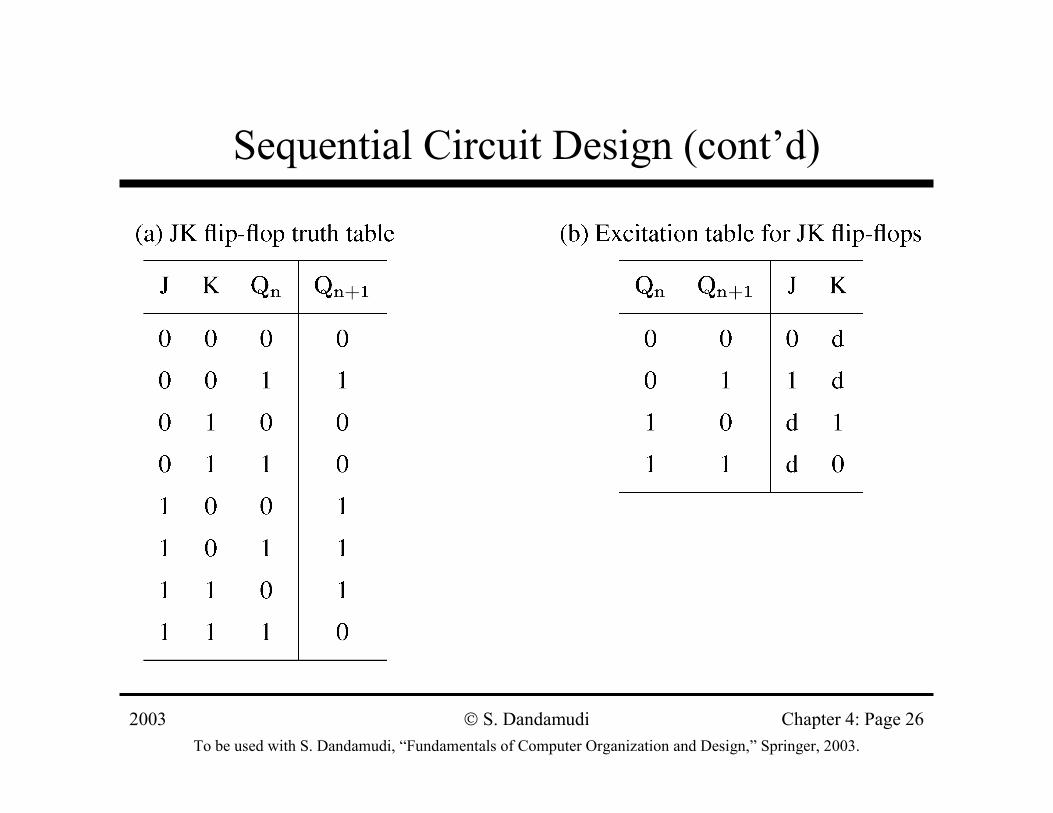
» Need to know the input combination that produces this output» Use an excitation table
– Built from the truth table
2003To be used with S. Dandamudi, “Fundamentals of Computer Organization and Design,” Springer, 2003.
S. Dandamudi Chapter 4: Page 26
Sequential Circuit Design (cont’d)
2003To be used with S. Dandamudi, “Fundamentals of Computer Organization and Design,” Springer, 2003.
S. Dandamudi Chapter 4: Page 27
Sequential Circuit Design (cont’d)
• Build a design table that consists of∗ Current state output∗ Next state output∗ JK inputs for each flip-flop
• Binary counter example∗ 3-bit binary counter∗ 3 JK flip-flops are needed∗ Current state and next state outputs are 3 bits each∗ 3 pairs of JK inputs
2003To be used with S. Dandamudi, “Fundamentals of Computer Organization and Design,” Springer, 2003.
S. Dandamudi Chapter 4: Page 28
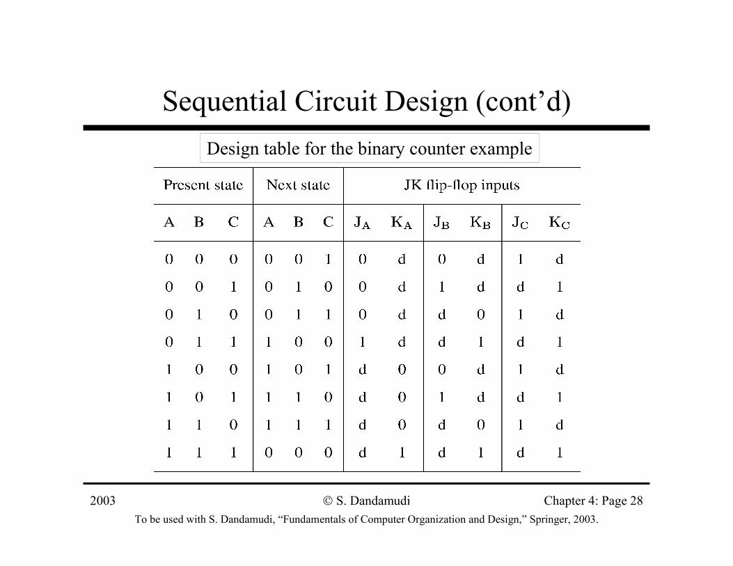
Sequential Circuit Design (cont’d)Design table for the binary counter example
2003To be used with S. Dandamudi, “Fundamentals of Computer Organization and Design,” Springer, 2003.
S. Dandamudi Chapter 4: Page 29
Sequential Circuit Design (cont’d)
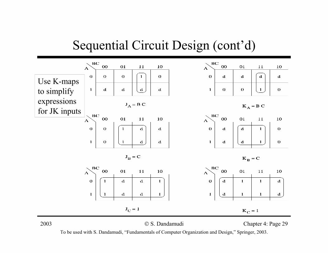
Use K-maps to simplify expressions for JK inputs
2003To be used with S. Dandamudi, “Fundamentals of Computer Organization and Design,” Springer, 2003.
S. Dandamudi Chapter 4: Page 30
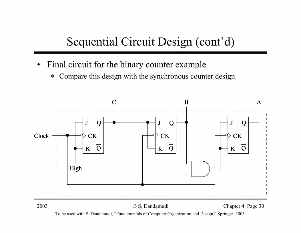
Sequential Circuit Design (cont’d)
• Final circuit for the binary counter example∗ Compare this design with the synchronous counter design
2003To be used with S. Dandamudi, “Fundamentals of Computer Organization and Design,” Springer, 2003.
S. Dandamudi Chapter 4: Page 31
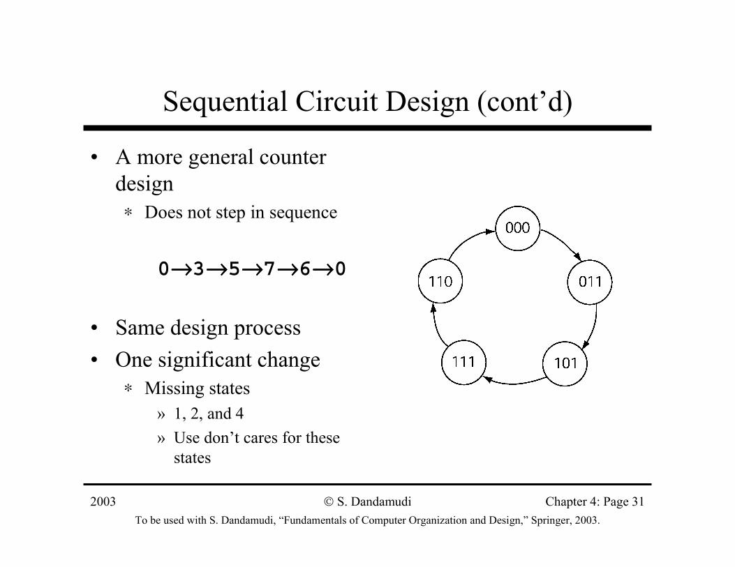
Sequential Circuit Design (cont’d)
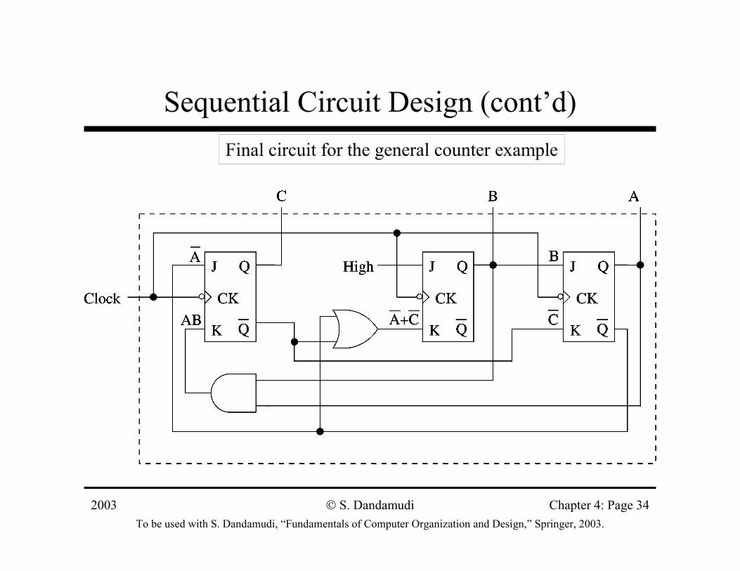
• A more general counter design∗ Does not step in sequence
0→→→→3→→→→5→→→→7→→→→6→→→→0
• Same design process• One significant change
∗ Missing states» 1, 2, and 4» Use don’t cares for these
states
2003To be used with S. Dandamudi, “Fundamentals of Computer Organization and Design,” Springer, 2003.
S. Dandamudi Chapter 4: Page 32
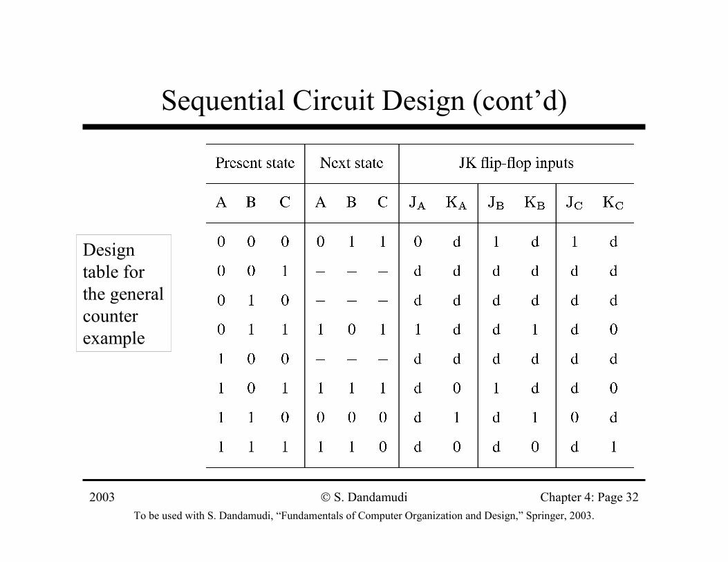
Sequential Circuit Design (cont’d)
Design table for the general counter example
2003To be used with S. Dandamudi, “Fundamentals of Computer Organization and Design,” Springer, 2003.
S. Dandamudi Chapter 4: Page 33
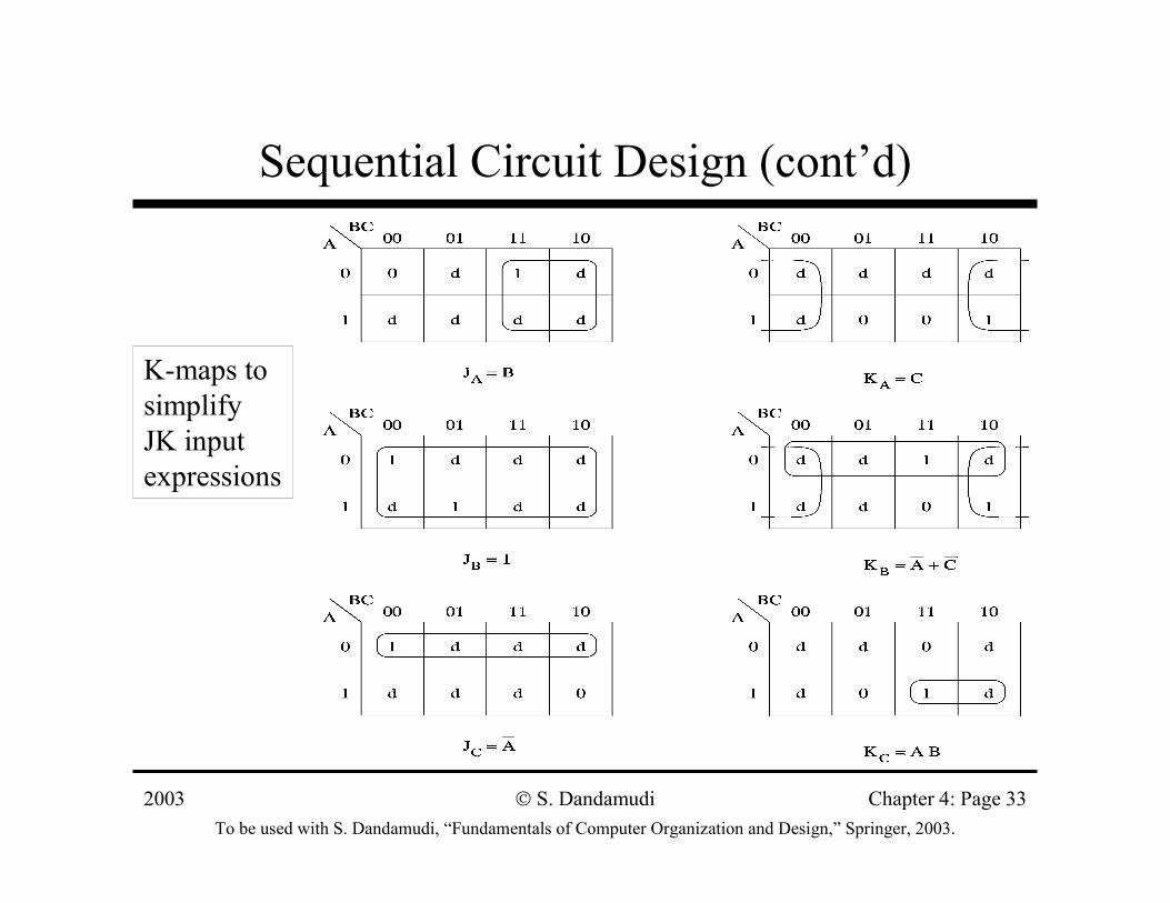
Sequential Circuit Design (cont’d)
K-maps to simplify JK input expressions
2003To be used with S. Dandamudi, “Fundamentals of Computer Organization and Design,” Springer, 2003.
S. Dandamudi Chapter 4: Page 34
Sequential Circuit Design (cont’d)Final circuit for the general counter example
2003To be used with S. Dandamudi, “Fundamentals of Computer Organization and Design,” Springer, 2003.
S. Dandamudi Chapter 4: Page 35
General Design Process
• FSM can be used to express the behavior of a sequential circuit
» Counters are a special case
∗ State transitions are indicated by arrows with labels X/Y
» X: inputs that cause system state change» Y: output generated while moving to the next state
• Look at two examples∗ Even-parity checker∗ Pattern recognition
2003To be used with S. Dandamudi, “Fundamentals of Computer Organization and Design,” Springer, 2003.
S. Dandamudi Chapter 4: Page 36
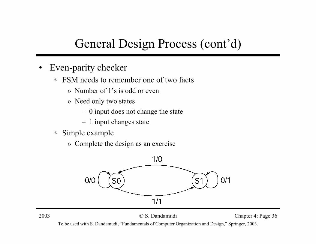
General Design Process (cont’d)
• Even-parity checker∗ FSM needs to remember one of two facts
» Number of 1’s is odd or even» Need only two states
– 0 input does not change the state– 1 input changes state
∗ Simple example » Complete the design as an exercise
2003To be used with S. Dandamudi, “Fundamentals of Computer Organization and Design,” Springer, 2003.
S. Dandamudi Chapter 4: Page 37
General Design Process (cont’d)
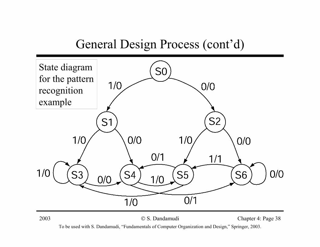
• Pattern recognition example∗ Outputs 1 whenever the input bit sequence has exactly
two 0s in the last three input bits∗ FSM requires thee special states to during the initial
phase » S0 − S2
∗ After that we need four states» S3: last two bits are 11» S4: last two bits are 01» S5: last two bits are 10» S6: last two bits are 00
2003To be used with S. Dandamudi, “Fundamentals of Computer Organization and Design,” Springer, 2003.
S. Dandamudi Chapter 4: Page 38
General Design Process (cont’d)
State diagram for the pattern recognition example
2003To be used with S. Dandamudi, “Fundamentals of Computer Organization and Design,” Springer, 2003.
S. Dandamudi Chapter 4: Page 39
General Design Process (cont’d)
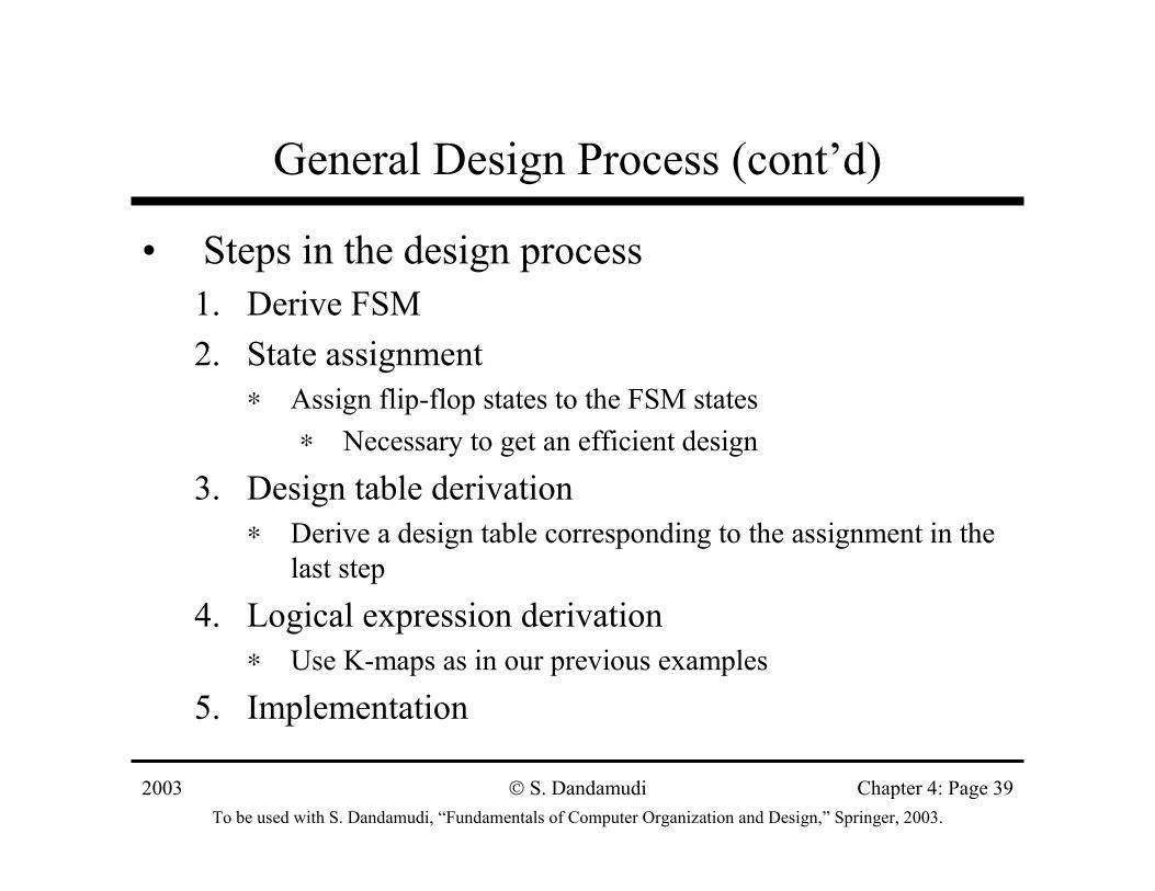
• Steps in the design process1. Derive FSM2. State assignment
∗ Assign flip-flop states to the FSM states∗ Necessary to get an efficient design
3. Design table derivation∗ Derive a design table corresponding to the assignment in the
last step
4. Logical expression derivation∗ Use K-maps as in our previous examples
5. Implementation
2003To be used with S. Dandamudi, “Fundamentals of Computer Organization and Design,” Springer, 2003.
S. Dandamudi Chapter 4: Page 40
General Design Process (cont’d)
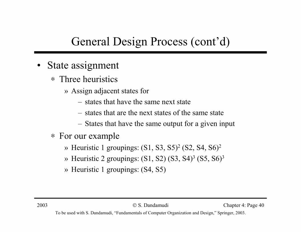
• State assignment∗ Three heuristics
» Assign adjacent states for– states that have the same next state– states that are the next states of the same state– States that have the same output for a given input
∗ For our example» Heuristic 1 groupings: (S1, S3, S5)2 (S2, S4, S6)2
» Heuristic 2 groupings: (S1, S2) (S3, S4)3 (S5, S6)3
» Heuristic 1 groupings: (S4, S5)
2003To be used with S. Dandamudi, “Fundamentals of Computer Organization and Design,” Springer, 2003.
S. Dandamudi Chapter 4: Page 41
General Design Process (cont’d)
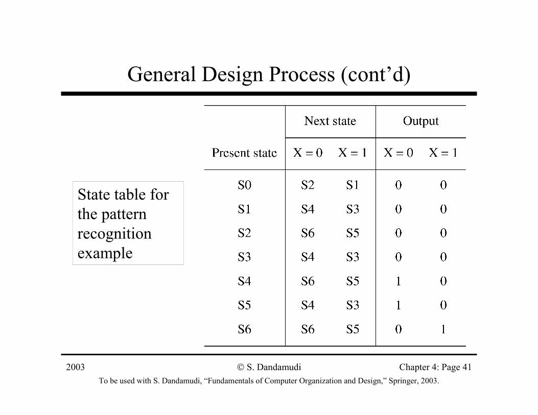
State table for the pattern recognition example
2003To be used with S. Dandamudi, “Fundamentals of Computer Organization and Design,” Springer, 2003.
S. Dandamudi Chapter 4: Page 42
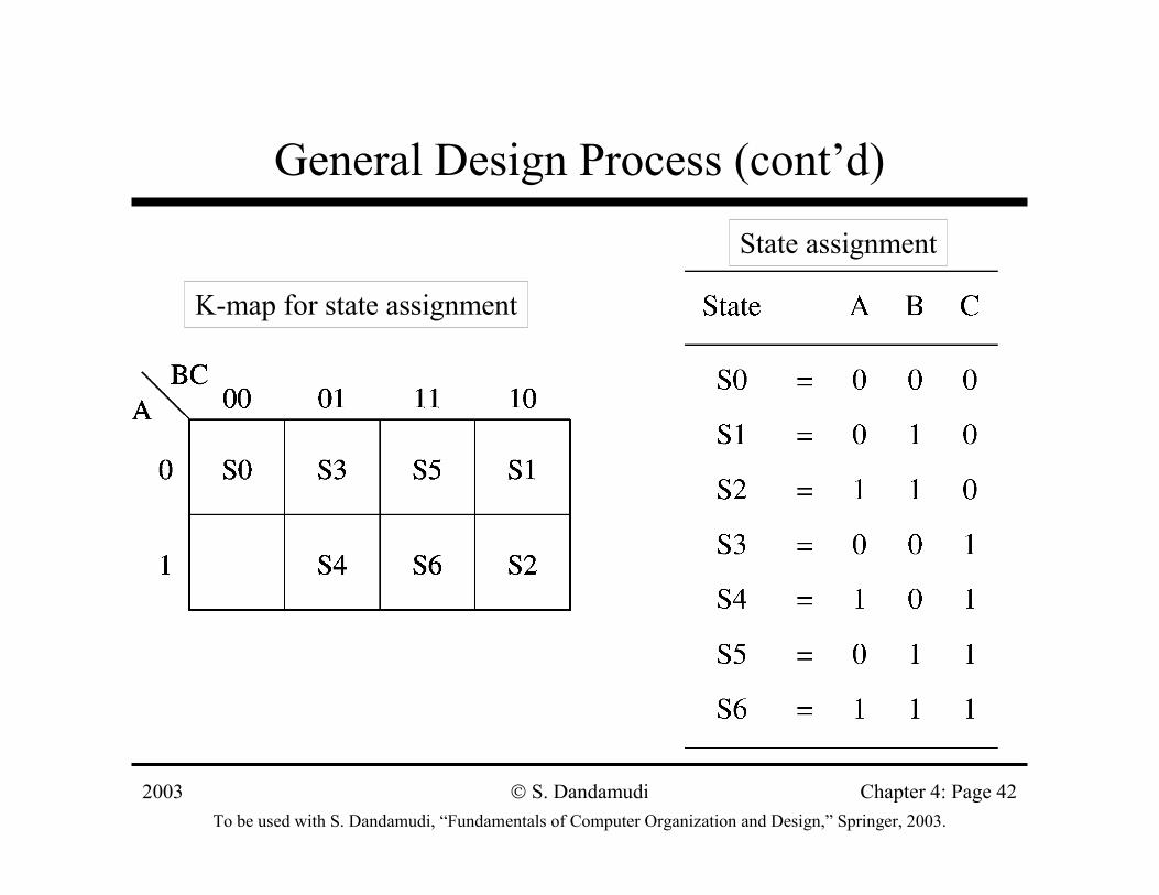
General Design Process (cont’d)
State assignment
K-map for state assignment
2003To be used with S. Dandamudi, “Fundamentals of Computer Organization and Design,” Springer, 2003.
S. Dandamudi Chapter 4: Page 43
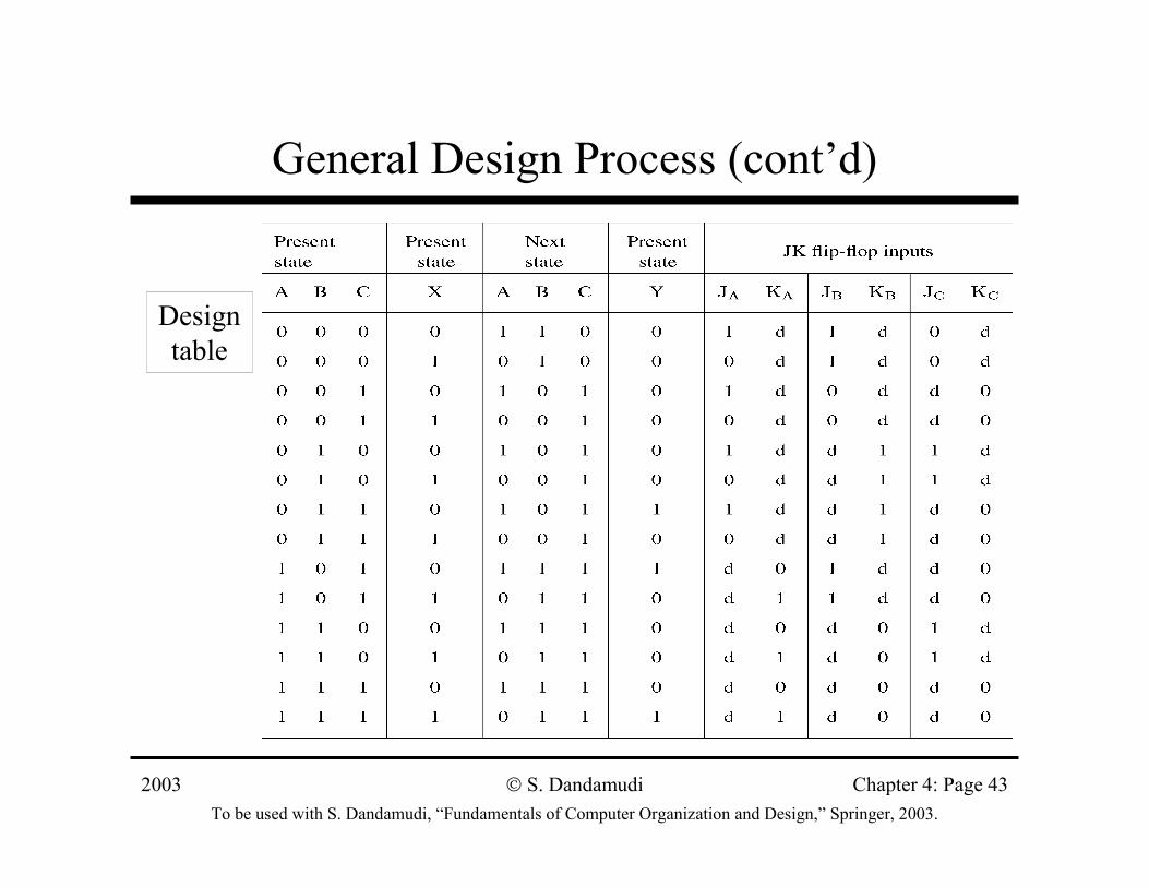
General Design Process (cont’d)
Design table
2003To be used with S. Dandamudi, “Fundamentals of Computer Organization and Design,” Springer, 2003.
S. Dandamudi Chapter 4: Page 44
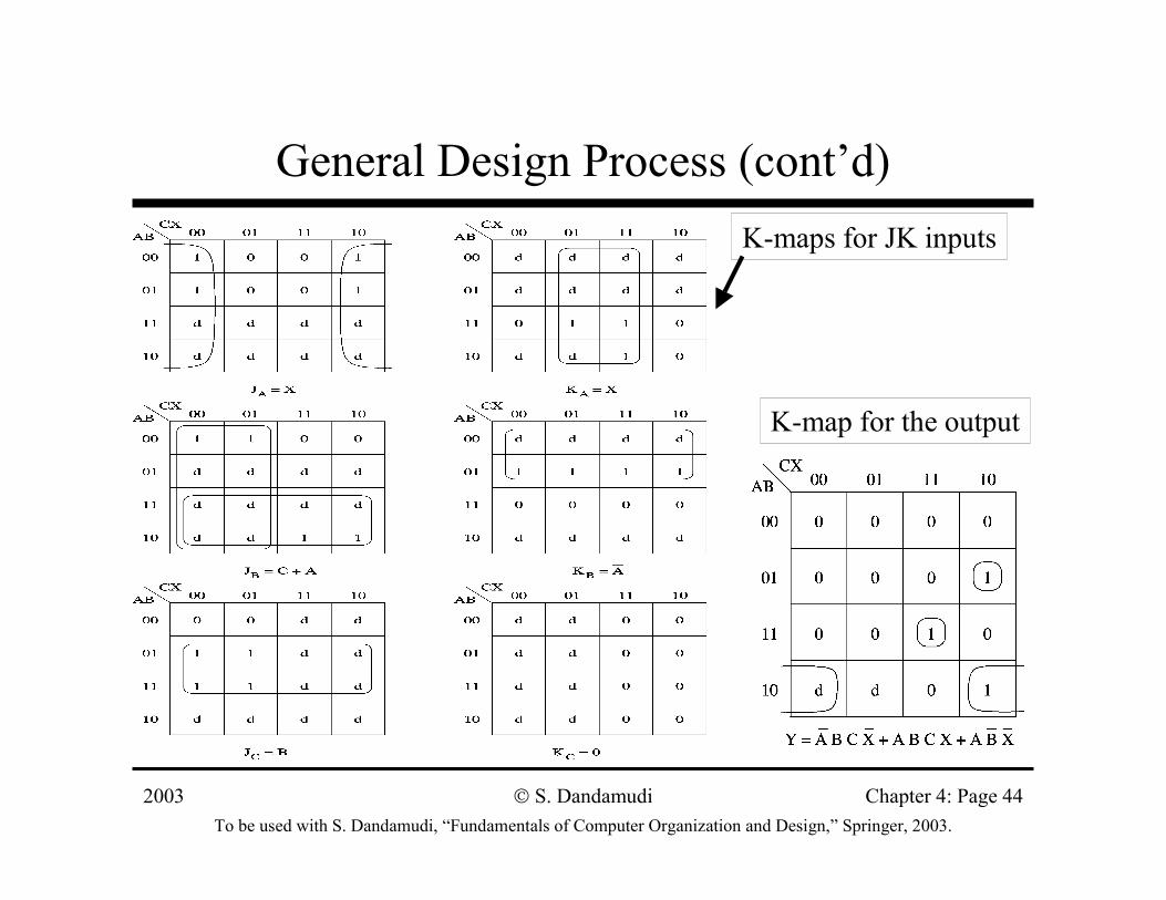
General Design Process (cont’d)K-maps for JK inputs
K-map for the output
2003To be used with S. Dandamudi, “Fundamentals of Computer Organization and Design,” Springer, 2003.
S. Dandamudi Chapter 4: Page 45
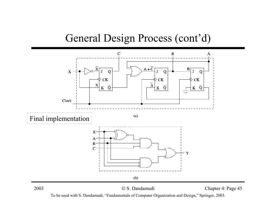
General Design Process (cont’d)
Final implementation
2003To be used with S. Dandamudi, “Fundamentals of Computer Organization and Design,” Springer, 2003.
S. Dandamudi Chapter 4: Page 46
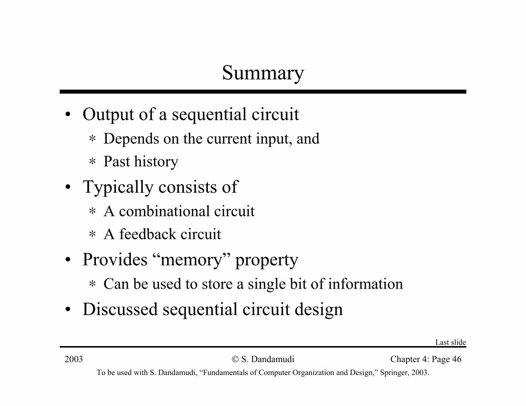
Summary
• Output of a sequential circuit∗ Depends on the current input, and∗ Past history
• Typically consists of ∗ A combinational circuit∗ A feedback circuit
• Provides “memory” property∗ Can be used to store a single bit of information
• Discussed sequential circuit designLast slide
Recommended


![Actigomenroute [PDF, 2 blz, 3,41 MB] · 0 0 0 0 0 0 0 0 0 0 0 0 0 0 0 0 0 0 0 0 0 0 0 0 0 0 0 0 0 0 0 0 60 0 0 0 0 0 5 5 0 60 60 0 0 0 0 0 0 0 0 5 5 0 0 60 60 0 0 0 0 0 0 0 0 0 0](https://img.pdfslide.net/doc/110x75/60c8b2b62084147a4c1c9962/actigomenroute-pdf-2-blz-341-mb-0-0-0-0-0-0-0-0-0-0-0-0-0-0-0-0-0-0-0-0-0-0.jpg)


![[XLS] · Web view0 0 0 0 0 0 0 0 0 0 0 0 0 0 0 0 0 0 0 0 0 0 0 0 7 2 0 0 0 0 0 0 0 0 0 0 0 5 4 0 0 0 0 0 0 0 0 0 0 0 5 4 0 0 0 0 0 0 0 0 0 0 0 5 4 0 0 0 0 0 0 0 0 0 0 0 5 4 0 0 0 0](https://img.pdfslide.net/doc/110x75/5aad015d7f8b9a8d678d9907/xls-view0-0-0-0-0-0-0-0-0-0-0-0-0-0-0-0-0-0-0-0-0-0-0-0-7-2-0-0-0-0-0-0-0-0-0.jpg)