79
chapter three
Environmental Factors
The evolution of building construction practices throughout the twentieth century has left a spectrum of good and bad practices that architects, engi-neers, contractors, planners, civic officials, and property owners must recog-nize to facilitate their efforts to achieve sustainability. Changes in architectural building technologies, particularly in the period after World War II, led to dramatic shifts in how buildings were designed, built, and operated. The na-scent passive solar energy movement coupled with the two energy crises of the 1970s that prompted dramatic energy cost increases and heightened con-cerns over energy security led to a different way to view building performance. Building designers seemed to take note of these lessons and began to design more energy-efficient buildings.
Fuel prices and availability stabilized in the 1980s yet still remain high com-pared with those of the pre-crisis period. However, uncertainty in fuel cost escalation creates growing concerns over energy security and the long-term sustainability of buildings. The numerous energy retrofits completed in the 1980s revealed that there were many alternative solutions to reducing energy use, some of which translate directly from constructing new buildings to retro-fitting existing ones. The techniques that translated well included upgrading operational and control aspects of mechanical, electrical, plumbing, and light-ing systems with more energy-efficient replacement products or control over-lays programmed to use less energy. Modifications to the building envelope that emulated new building construction led to adding insulation to walls and roofs and infilling windows with insulated panels or replacing them altogether. Unfortunately, in certain instances the cost of removing preexisting envelope components, such as windows, made the proposed strategy cost-prohibitive.
Decision makers started paying greater attention to energy payback peri-ods and specifically kept first costs to a minimum and focused on recover-ing the cost of more incrementally expensive design alternatives through the
OI 10. /978- - - _ , © ,
5822 1 61091-236 201 Island PressR.A. Young, Stewardship of the Built Environment: Sustainability, Preservation, and ReuseMetropolitan Planning + Design, D 5 23
80 Stewardship of the Built Environment
expected energy savings alone. These analysis methods have since been sup-plemented and even surpassed through the use of life cycle analysis software and databases.
At this same time, design professionals began to recognize the inherent sus-tainability present in many of the features common to buildings built before the mid-1950s. Initial attempts to conserve energy by infilling windows with materials designed to resist heat loss often resulted in higher electrical lighting costs because they blocked daylight. Studies began to reveal that the long-forgotten or overlooked strategies of using thermal mass to moderate tempera-ture swings or taking advantage of natural ventilation could play an important role in energy performance. The more thermally massive buildings built before World War II had different operating characteristics than the less thermally massive curtain wall of the post–World War II era. These and other character-istics of architectural form and tectonics are discussed in further detail in this chapter.
This chapter begins with an examination of how environmental indica-tors apply to existing buildings as metrics for performance. Then it explores the opportunities and constraints that existing buildings place on efforts to achieve sustainability. The chapter concludes with an exploration of current environmental trends that provide opportunities to improve stewardship of the built environment.
Environmental Indicators
In addition to Leadership in Energy and Environmental Design (LEED), several other quantification systems are available worldwide. The US Envi-ronmental Protection Agency and the US Department of Energy developed Energy Star (USEPA-USDOE 2011) in 1992 to originally assess various ap-pliances and by 1995 had expanded the program to include businesses and homes. Although LEED has dominated the market, Energy Star is a comple-mentary system that is gaining broader use. Two other programs, the Build-ing Research Establishment Environmental Assessment Method (BREEAM 2011) and the Green Building Initiative’s Green Globes (Green Building Ini-tiative 2011), respectively developed in the United Kingdom and Canada, have gained an international following.
Environmental Factors 81
Designers and analysts compare the environmental performance of various buildings at a comprehensive scale or the potential benefits of various alter-native design options. Several environmental indicators are commonly used to measure building performance. These include the energy utilization index (EUI), embodied energy invested in existing buildings, material flows from raw materials to landfill wastes, and life cycle analysis.
Energy Utilization Index
The EUI measures energy use by taking the sum of the total energy usage for heating, cooling, lighting, and electrical plug loads for the study period (typically 1 year) divided by the gross area of the building. This is expressed in kilo–British thermal units (kBtu). Some analysts express the EUI in Brit-ish thermal units per square foot, so you must pay attention to the units being used when comparing different projects. Thus, the EUI formula becomes
EUI (kBtu/sf) = Total energy usage (kBtu)/Gross building area (sf).
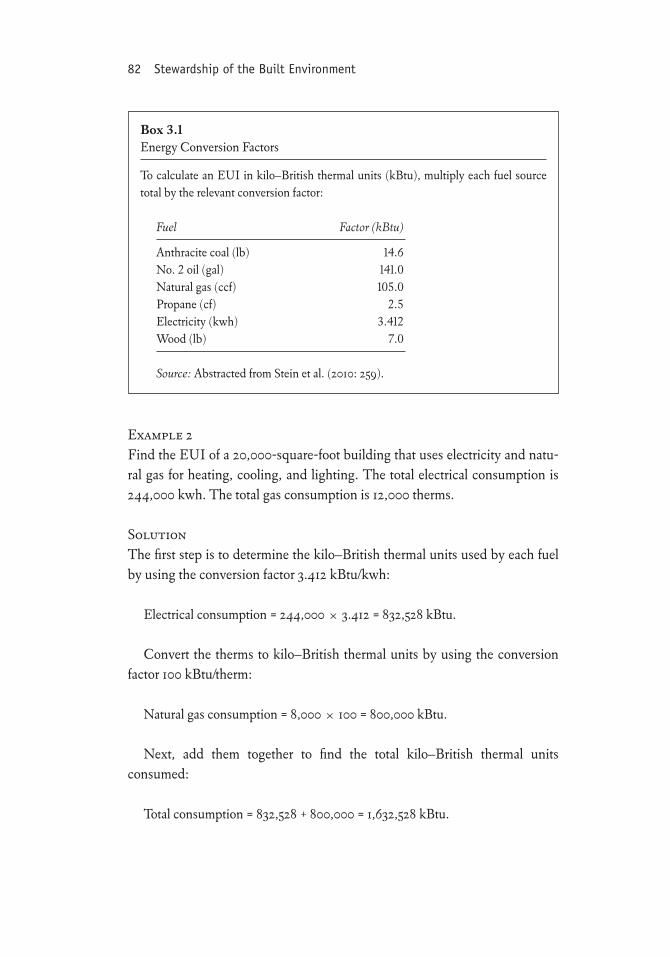
When more than one fuel is used, convert each source total to kilo–British thermal units (box 3.1) and then add them together to find the total energy use. The results give a relative indication of the energy use profile that can be used to assess the general energy performance of buildings of different sizes or construction periods. The following examples illustrate how the EUI is determined.
Example 1Find the EUI of a 16,000-square-foot building that uses only electricity for heating, cooling, and lighting and has used a total of 481,500 kwh.
SolutionThe first step is to convert the kilowatt hours to kilo–British thermal units by using the conversion factor 3.412 kBtu/kwh:
Total energy usage = 481,500 ≈ 3.412 = 1,642,878 kBtu.
The second step is to divide the result by the gross square footage of the building to obtain the EUI:
EUI = 1,642,878/16,000 sf = 102.7 kBtu/sf.
82 Stewardship of the Built Environment
Example 2Find the EUI of a 20,000-square-foot building that uses electricity and natu-ral gas for heating, cooling, and lighting. The total electrical consumption is 244,000 kwh. The total gas consumption is 12,000 therms.
SolutionThe first step is to determine the kilo–British thermal units used by each fuel by using the conversion factor 3.412 kBtu/kwh:
Electrical consumption = 244,000 ≈ 3.412 = 832,528 kBtu.
Convert the therms to kilo–British thermal units by using the conversion factor 100 kBtu/therm:
Natural gas consumption = 8,000 ≈ 100 = 800,000 kBtu.
Next, add them together to find the total kilo–British thermal units consumed:
Total consumption = 832,528 + 800,000 = 1,632,528 kBtu.
Box 3.1Energy Conversion Factors
To calculate an EUI in kilo–British thermal units (kBtu), multiply each fuel source total by the relevant conversion factor:
Fuel Factor (kBtu)
Anthracite coal (lb) 14.6No. 2 oil (gal) 141.0Natural gas (ccf) 105.0Propane (cf) 2.5Electricity (kwh) 3.412Wood (lb) 7.0
Source: Abstracted from Stein et al. (2010: 259).
Environmental Factors 83
The final step is to divide the kilo–British thermal units used by the gross square footage of the building to obtain the EUI:
EUI = 1,632,528/20,000 sf = 81.6 kBtu/sf.
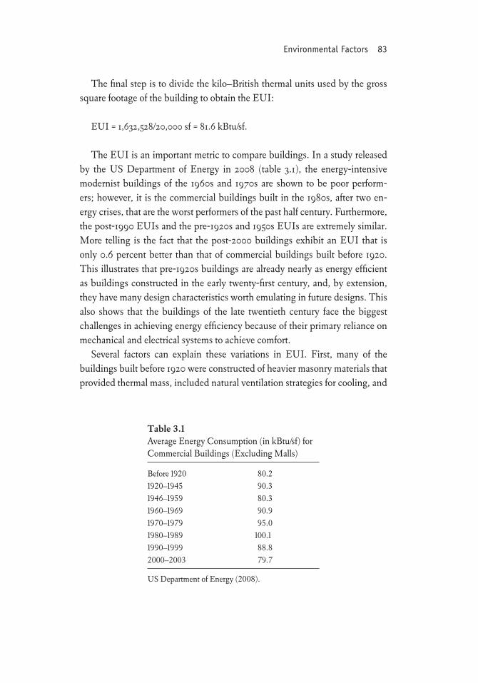
The EUI is an important metric to compare buildings. In a study released by the US Department of Energy in 2008 (table 3.1), the energy-intensive modernist buildings of the 1960s and 1970s are shown to be poor perform-ers; however, it is the commercial buildings built in the 1980s, after two en-ergy crises, that are the worst performers of the past half century. Furthermore, the post-1990 EUIs and the pre-1920s and 1950s EUIs are extremely similar. More telling is the fact that the post-2000 buildings exhibit an EUI that is only 0.6 percent better than that of commercial buildings built before 1920. This illustrates that pre-1920s buildings are already nearly as energy efficient as buildings constructed in the early twenty-first century, and, by extension, they have many design characteristics worth emulating in future designs. This also shows that the buildings of the late twentieth century face the biggest challenges in achieving energy efficiency because of their primary reliance on mechanical and electrical systems to achieve comfort.
Several factors can explain these variations in EUI. First, many of the buildings built before 1920 were constructed of heavier masonry materials that provided thermal mass, included natural ventilation strategies for cooling, and
Table 3.1Average Energy Consumption (in kBtu/sf) for Commercial Buildings (Excluding Malls)
Before 1920 80.21920–1945 90.31946–1959 80.31960–1969 90.91970–1979 95.01980–1989 100.11990–1999 88.82000–2003 79.7
US Department of Energy (2008).
84 Stewardship of the Built Environment
relied a great deal on daylighting. Although invented in the early twentieth century, air conditioning did not become widely used until after World War II. Fluorescent lamps and double-paned windows were introduced in the 1930s, and the aluminum curtain wall gained greater use in the 1950s and beyond. Their use transformed buildings as operable windows, atria, thermal mass, and other pre-1920 standard design elements disappeared from the mid-twen-tieth-century design mindset. At one point, with the advent of commercially available nuclear electrical power sources, the promise of electrical power “too cheap to meter” (Adams 2005) led to greater reliance on even larger and more complex heating, ventilating, and air conditioning systems to offset any com-fort problems created by thermal deficiencies in the building. This expanding cycle of energy use and design insensitivity continued well into the 1970s. In the 1990s, energy-sensitive designs began to gain popularity and, with the rise of greater public demand for sustainability, have taken firm hold of the build-ing industry.
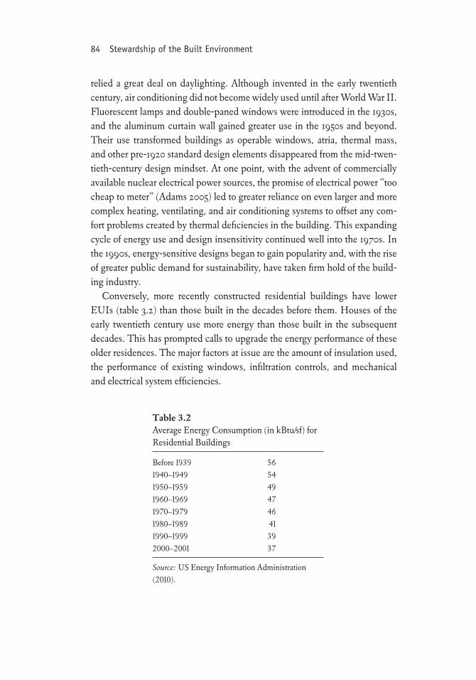
Conversely, more recently constructed residential buildings have lower EUIs (table 3.2) than those built in the decades before them. Houses of the early twentieth century use more energy than those built in the subsequent decades. This has prompted calls to upgrade the energy performance of these older residences. The major factors at issue are the amount of insulation used, the performance of existing windows, infiltration controls, and mechanical and electrical system efficiencies.
Table 3.2Average Energy Consumption (in kBtu/sf) for Residential Buildings
Before 1939 561940–1949 541950–1959 491960–1969 471970–1979 461980–1989 411990–1999 392000–2001 37
Source: US Energy Information Administration (2010).
Environmental Factors 85
Embodied Energy
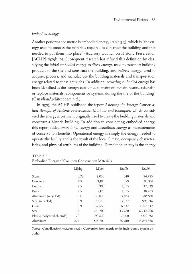
Another performance metric is embodied energy (table 3.3), which is “the en-ergy used to process the materials required to construct the building and that needed to put them into place” (Advisory Council on Historic Preservation [ACHP] 1979b: 6). Subsequent research has refined this definition by clas-sifying the initial embodied energy as direct energy, used to transport building products to the site and construct the building, and indirect energy, used to acquire, process, and manufacture the building materials and transportation energy related to these activities. In addition, recurring embodied energy has been identified as the “energy consumed to maintain, repair, restore, refurbish or replace materials, components or systems during the life of the building” (CanadianArchitect.com n.d.).
In 1979, the ACHP published the report Assessing the Energy Conserva-tion Benefits of Historic Preservation: Methods and Examples, which consid-ered the energy investment originally used to create the building materials and construct a historic building. In addition to considering embodied energy, this report added operational energy and demolition energy as measurements of conservation benefits. Operational energy is simply the energy needed to operate the facility and is the result of the local climate, occupancy character-istics, and physical attributes of the building. Demolition energy is the energy
Table 3.3Embodied Energy of Common Construction Materials
MJ/kg MJ/m3 Btu/lb Btu/ft3
Stone 0.79 2,030 340 54,485Concrete 1.3 3,180 559 85,351Lumber 2.5 1,380 1,075 37,039Brick 2.5 5,170 1,075 138,763Aluminum (recycled) 8.1 21,870 3,483 586,991Steel (recycled) 8.9 37,210 3,827 998,716Glass 15.9 37,550 6,837 1,007,842Steel 32 251,200 13,760 6,742,208Plastic (polyvinyl chloride) 70 93,620 30,100 2,512,761Aluminum 227 515,700 97,610 13,841,388
Source: CanadianArchitect.com (n.d.). Conversion from metric to the inch–pound system by author.
86 Stewardship of the Built Environment
needed to raze, load, and haul away demolition materials but does not include any energy savings from recycled or salvaged materials (ACHP 1979a: 8).
The National Trust for Historic Preservation (NTHP) was an early ad-vocate promoting the inherent energy savings accrued by reusing buildings rather than replacing them with entirely new buildings. But the attitudes of the era did not foster broad acceptance of the concept. Even today the argu-ment for measuring embodied energy to justify the retention of a building is met with skepticism. In business accounting terms, embodied energy repre-sents a sunk cost, which, except as a baseline for potential recurring savings accrued when compared with an alternative solution, is not included in deci-sions about future expenses. Although the arguments for avoiding the energy consumed in demolition and the embodied energy used to create a new build-ing remain viable, what has emerged in the past two decades is the concept of avoided impacts, or minimizing (if not eliminating) energy use for demolition and new construction. The avoided impacts have been expressed in a number of ways in a broad spectrum of business decisions. An early example of this was the Environmental Protection Agency “Green Lights” program, which advocated the use of energy-efficient lighting both as a money-saving strategy and as a means to reduce energy consumption that in turn reduced the impact of power plant emissions and improve air quality. Expansion of the concep-tual framework for embodied energy has occurred in other sectors to include embodied carbon and embodied water (Carroon 2010: 260–161). Quantifica-tion methods that incorporate embodied carbon (e.g., inventory of carbon and energy, the embodied carbon metric, and the carbon footprint calculator) and embodied water (e.g., water footprint) are gaining in usage as well.
This perspective also necessitates understanding that any energy used to create and construct a new building must be recovered before that new build-ing saves any energy that contributes toward sustainability goals. A new “sus-tainable” house may take 12–15 years to recover the energy used to create and transport the building materials to the job site and fabricate the building. Raz-ing a house to replace it with a similar but more energy-efficient house (which some call conspicuous conservation) (Curtis 2008) will nearly double the re-covery period because of the demolition and transport energy and the embod-ied energy of the original house.
When many sustainability proponents talk of creating a sustainable envi-ronment by focusing solely on tearing down old buildings and replacing them
Environmental Factors 87
with buildings that are more energy efficient, they typically justify the benefits based solely on the lower operational energy usage of the new building com-pared with the existing building. This view does not account for the embod-ied energy needed to construct the new building nor the demolition energy needed to remove the existing building, and it disregards the embodied energy in the existing building. As Mike Jackson of the Illinois State Historic Preser-vation Office (SHPO) states,
Embodied energy deserves to be another factor in the equation of sustainable design, particularly for historic preservation. The built environment represents a huge resource that can be conserved and made efficient for the twenty-first century challenge of fossil fuel exhaustion. . . . By combining preservation principles and the concept of embodied energy, a stronger argument for the environmental benefits of building reuse can be made. (Jackson 2005: 51)
In support of this statement, Jackson provided the following two cases, which illustrate how the inclusion of embodied energy, demolition energy, and differences in energy consumption projections between new and existing buildings can be interpreted, even when the new building is constructed to high-performance building standards.
Case 1Do nothing to the existing building and build a new building. The existing building will be reused by a different user.
Embodied energy for new building: 1,200 kBtu/sfExisting building annual operating energy: 70 kBtu/sfNew building annual operating energy: 35 kBtu/sf
Calculate the energy recovery rate (the consumption difference between the new and the existing buildings):
Energy recovery rate = Energy rateexisting – Energy ratenew = 70 – 35 = 35 kBtu/sf.
Calculate the recovery period for the embodied energy expended to con-struct the new building:
88 Stewardship of the Built Environment
Energy recovery period = Initial embodied energy/Energy recovery rate = 1,200/35 = 34.2 years.
It will take 34.2 years to recover the energy used to construct the building before any energy is saved.
Case 2Salvage a portion of the existing building and demolish the remainder. Re-place it with a new building.
Lost embodied energy for existing building: 1,200 kBtu/sfRecovered embodied energy for salvaged materials: –400 kBtu/sfEmbodied energy for new building: 1,200 kBtu/sfTotal embodied energy of the project: 2,000 kBtu/sfExisting building annual operating energy: 70 kBtu/sfNew building annual operating energy: 35 kBtu/sf
Calculate the energy recovery rate:
Energy recovery rate = Energy rateexisting – Energy ratenew = 70 – 35 = 35 kBtu/sf.
Calculate the period needed to recover the embodied energy expended to construct the new building:
Energy recovery period = Initial embodied energy/Energy recovery rate = 2,000/35 = 57.2 years.
It will take 57.2 years to recover the energy used to construct the new build-ing and demolish or salvage the existing building before any real energy is saved.
Note that without the embodied energy from salvage, this period increases to 68.6 years. Salvage and deconstruction currently represent a small fraction of what their embodied energy savings could be when they are fully available nationwide.
Case 1 shows that the recovery period is excessive even if the owner simply opted to build on open suburban land. This approach contributes to green
Environmental Factors 89
sprawl, as described in chapter 1. Case 2 presents a controversial point that many designers and property owners do not understand: the significance of the demolished building’s lost embodied energy. In each scenario, the energy recovery period exceeds the expected useful lives of many buildings being constructed today. There is no real return on investment in terms of energy because following the mindset of “demolish and rebuild” or “build new in the suburban periphery” would repeat these wasteful practices before the recovery period concludes.
Material Flow
“Reduce, reuse, and recycle” (3R) is the mantra to keep recyclable materials in use and out of landfills. As noted in Green Builders (NJN Public Televi-sion and Radio 2009), building construction consumes 40 percent of world’s resources and contributes 40 percent of the material going into landfills. This flow could be reduced by reusing buildings, which has been called the “high-est” (Young 1998), “most efficient” (Cockram 2005: B.1.2), and “ultimate” (Rypkema 2007a; Young 2008b) form of recycling. The 3R philosophy has public support when it comes to aluminum, glass, and plastic containers but falls short of the same public application when it comes to buildings. Donovan Rypkema (2007b) noted that a typical building in an American downtown is perhaps 25 feet wide and 120 feet deep (fig. 3.1), and to tear it down would wipe out the entire environmental benefit from 1,344,000 aluminum cans that were recycled—just in terms of the comparative volume of material sent to a landfill. This does not include the embodied energy lost.
One alternative to razing a building is to move the building in its entirety. Wood-framed buildings have been routinely moved despite the potential ob-structions posed by overhead telephone and power lines. Moving masonry buildings is more problematic. The sheer volume and weight of masonry build-ings, especially when coupled with the perceived challenge of adequately sta-bilizing unreinforced masonry construction, have often precluded their being moved out of the path of the developer’s wrecking ball. Two recent examples show how the concept of recycling and resource reuse can be accomplished in spectacular but increasingly attainable fashion.
These include the relocation of the Odd Fellows Hall (OFH) in Salt Lake City, Utah and the Showley Brothers Candy Factory in San Diego, California.
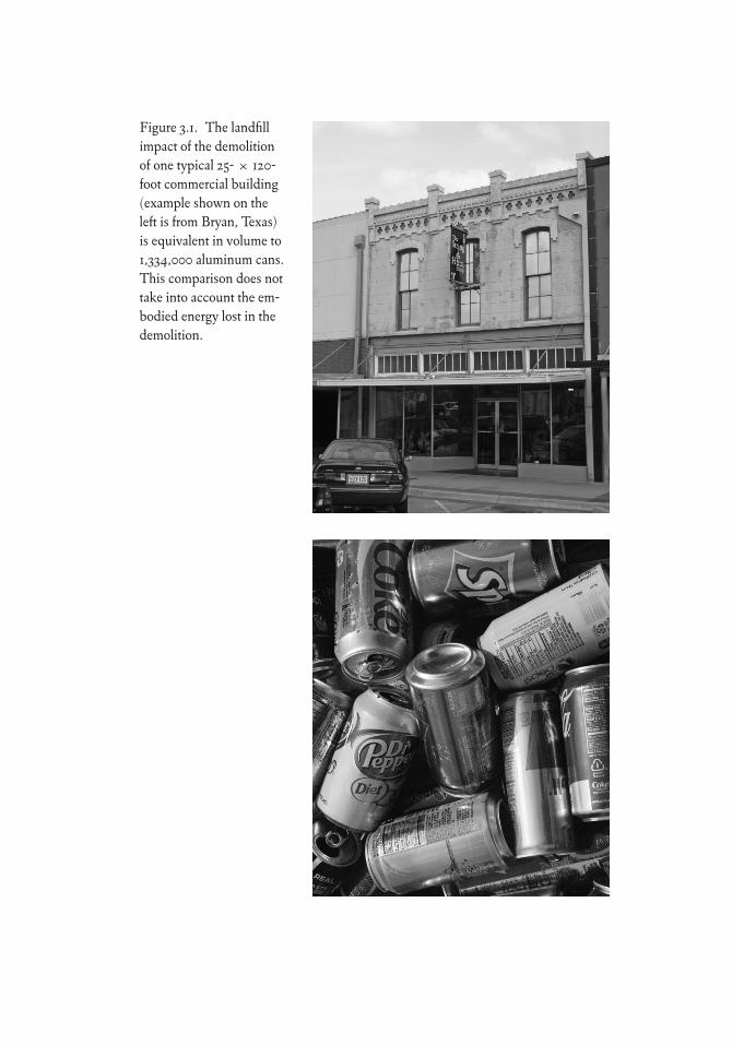
Figure 3.1. The landfill impact of the demolition of one typical 25- ≈ 120-foot commercial building (example shown on the left is from Bryan, Texas) is equivalent in volume to 1,334,000 aluminum cans. This comparison does not take into account the em-bodied energy lost in the demolition.
Environmental Factors 91
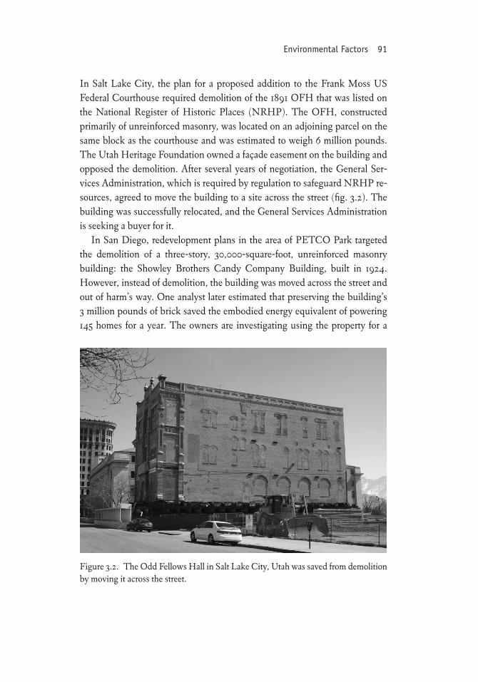
In Salt Lake City, the plan for a proposed addition to the Frank Moss US Federal Courthouse required demolition of the 1891 OFH that was listed on the National Register of Historic Places (NRHP). The OFH, constructed primarily of unreinforced masonry, was located on an adjoining parcel on the same block as the courthouse and was estimated to weigh 6 million pounds. The Utah Heritage Foundation owned a façade easement on the building and opposed the demolition. After several years of negotiation, the General Ser-vices Administration, which is required by regulation to safeguard NRHP re-sources, agreed to move the building to a site across the street (fig. 3.2). The building was successfully relocated, and the General Services Administration is seeking a buyer for it.
In San Diego, redevelopment plans in the area of PETCO Park targeted the demolition of a three-story, 30,000-square-foot, unreinforced masonry building: the Showley Brothers Candy Company Building, built in 1924. However, instead of demolition, the building was moved across the street and out of harm’s way. One analyst later estimated that preserving the building’s 3 million pounds of brick saved the embodied energy equivalent of powering 145 homes for a year. The owners are investigating using the property for a
Figure 3.2. The Odd Fellows Hall in Salt Lake City, Utah was saved from demolition by moving it across the street.
92 Stewardship of the Built Environment
restaurant and commercial office space (Save Our Heritage Organisation 2011; Sandiegotraveltips.com 2011).
In many cities, deconstruction and salvage companies remove materi-als from the construction and demolition (C&D) waste stream. The C&D waste stream is composed of bricks, concrete, masonry, soil, lumber, paving materials, shingles, glass, plastics, aluminum, steel, drywall, insulation, roof-ing materials, plumbing fixtures, electrical materials, siding, packaging, and tree stumps. These operations provide resources used by many preservation-ists to obtain duplicate components for preservation or adaptive use projects. Although deconstructing and recycling building materials is an increasingly important part of building demolition, the full potential impact of this activity has yet to be reached because the infrastructure for its broader implementation is still in development. The Institute for Local Self-Reliance (ILSR) reports,
The EPA estimates that in 2003, an estimated 170 million tons of debris were generated from building, renovation and demolition projects across the United States. Through deconstruction and recovery, much of this material can be di-verted from landfills and reused. (ILSR n.d.)
Although the potential for reusing salvaged and deconstructed materials in their existing form occurs primarily in the preservation and renovation sector, this represents a small percentage of the market, and the remainder is typi-cally ground up, shredded, or reduced to its components and combined with raw materials to make products with “recycled content.” Given the practice of disposing C&D wastes in a landfill, communities, states, and federal agencies have instituted standards and ordinances to reshape these market forces. ILSR further states,
Communities can encourage the recycling of materials by making recovery part of the permitting process. A number of communities have passed local ordinances requiring recovery of C&D materials. In 1996, Portland, Oregon passed an ordinance requiring job-site recycling on all construction projects with a value exceeding $25,000. In 1999, Atherton, California passed an or-dinance that requires all construction, renovation and demolition projects to divert fifty percent of waste from landfills. Within the city, all buildings slated for demolition are made available for deconstruction. The city of Chicago has a mandatory 50 percent recycling rate for C&D as of 2007. (ILSR n.d.)
Environmental Factors 93
If the retention of an existing building is not possible, then, with sufficient awareness of the benefits of deconstruction, the demand for these services will grow and become a universal part of construction activity (fig. 3.3).
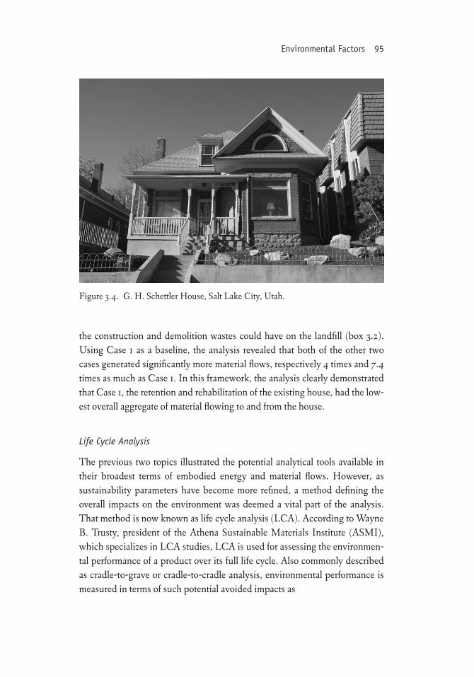
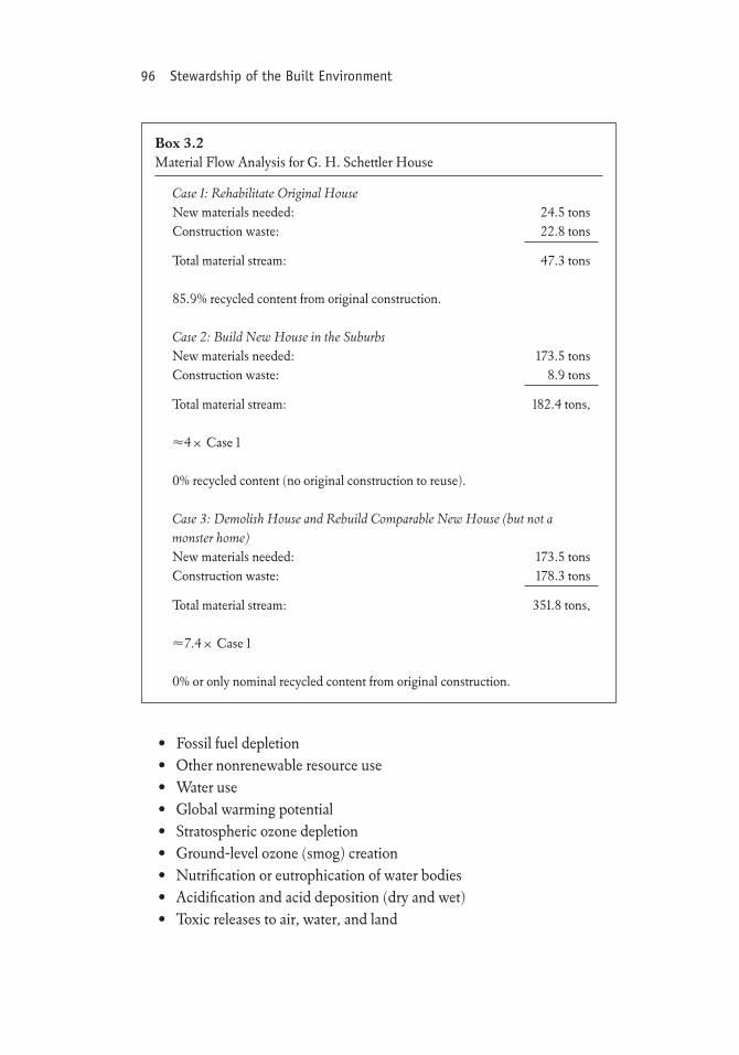
An analysis conducted on the G. H. Schettler House renovation in Salt Lake City, Utah compared material flows of three alternative cases commonly found in current design and construction practice (Young 2004b). The house is a two-story, detached single-family brick house (fig. 3.4) constructed in 1904 and located in a local and national historic district. In 2000, the house was updated to meet the demands of twenty-first-century urban living. All the mechanical, electrical, and plumbing systems were replaced to increase the livability of the building. Other improvements included weatherizing win-dows and doors, adding attic insulation, replacing the roof, upgrading bed-room windows to meet fire and life safety codes, and installing high-efficiency appliances, low-flow plumbing fixtures, and programmable controls for the heating, ventilation, and air conditioning (HVAC) system and exterior light-ing. The project, which can be described as a gut remodel, also replaced all the deteriorated plaster on the interior walls and restored or upgraded all interior finishes. Altogether, the upgrades resulted in a 37 percent reduction in heat-ing loads and a 22 percent reduction in cooling loads. The project was a Utah Residential Tax Credit project that came under both local Historic Landmark Commission and SHPO/National Park Service review for adherence to local design guidelines and the Secretary of the Interior’s Standards.
The goal of the research was to compare the aggregated flow of new materi-als going to the house and demolition materials leaving the house for the land-fill. For the comparison, the analysis defined three cases. Case 1 is the retention and rehabilitation of the existing house in keeping with the primary tenets of stewardship of the built environment. Case 2 is the construction of a similar house in the suburbs, representing the favored approach for many people to-day. Case 3 is the demolition and replication of the existing house to represent a conservative estimate of the material flows of the “monster home” invasions occurring in older neighborhoods nationwide. In this case, the conservative estimate is based on the fact that the replacement house is the same square footage as the original house, whereas in practice the replacement is typically a much larger “monster home.”
By calculating the amount of new materials used in the construction and the potential C&D waste stream of each scenario, the study analyzes the mate-rial flows, including the extraction of new raw materials and the impacts that
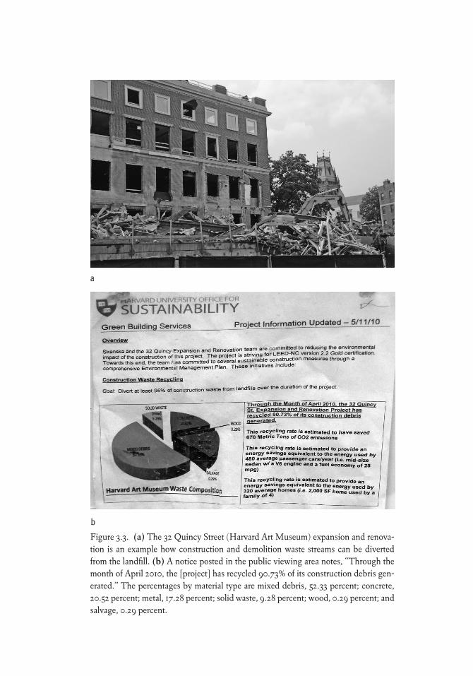
Figure 3.3. (a) The 32 Quincy Street (Harvard Art Museum) expansion and renova-tion is an example how construction and demolition waste streams can be diverted from the landfill. (b) A notice posted in the public viewing area notes, “Through the month of April 2010, the [project] has recycled 90.73% of its construction debris gen-erated.” The percentages by material type are mixed debris, 52.33 percent; concrete, 20.52 percent; metal, 17.28 percent; solid waste, 9.28 percent; wood, 0.29 percent; and salvage, 0.29 percent.
a
b
Environmental Factors 95
the construction and demolition wastes could have on the landfill (box 3.2). Using Case 1 as a baseline, the analysis revealed that both of the other two cases generated significantly more material flows, respectively 4 times and 7.4 times as much as Case 1. In this framework, the analysis clearly demonstrated that Case 1, the retention and rehabilitation of the existing house, had the low-est overall aggregate of material flowing to and from the house.
Life Cycle Analysis
The previous two topics illustrated the potential analytical tools available in their broadest terms of embodied energy and material flows. However, as sustainability parameters have become more refined, a method defining the overall impacts on the environment was deemed a vital part of the analysis. That method is now known as life cycle analysis (LCA). According to Wayne B. Trusty, president of the Athena Sustainable Materials Institute (ASMI), which specializes in LCA studies, LCA is used for assessing the environmen-tal performance of a product over its full life cycle. Also commonly described as cradle-to-grave or cradle-to-cradle analysis, environmental performance is measured in terms of such potential avoided impacts as
Figure 3.4. G. H. Schettler House, Salt Lake City, Utah.
96 Stewardship of the Built Environment
• Fossil fuel depletion• Other nonrenewable resource use• Water use• Global warming potential• Stratospheric ozone depletion• Ground-level ozone (smog) creation• Nutrification or eutrophication of water bodies• Acidification and acid deposition (dry and wet)• Toxic releases to air, water, and land
Box 3.2Material Flow Analysis for G. H. Schettler House
Case 1: Rehabilitate Original HouseNew materials needed: 24.5 tonsConstruction waste: 22.8 tons
Total material stream: 47.3 tons
85.9% recycled content from original construction.
Case 2: Build New House in the SuburbsNew materials needed: 173.5 tonsConstruction waste: 8.9 tons
Total material stream: 182.4 tons, 4≈ Case 1
0% recycled content (no original construction to reuse).
Case 3: Demolish House and Rebuild Comparable New House (but not a monster home)New materials needed: 173.5 tonsConstruction waste: 178.3 tons
Total material stream: 351.8 tons, 7.4≈ Case 1
0% or only nominal recycled content from original construction.
Environmental Factors 97
These are indicators of environmental loadings that can result from the manufacture, use, and disposal of a product (Trusty 2003: 2). The values for these parameters are part of a complex software modeling system that has more affinity for new construction because the current associative data are more readily available. As described by Jean Carroon, principal at Goody Clancy and author of Sustainable Preservation: Greening Existing Buildings, LCA is the holy grail of environmental evaluation. The National Renewable Energy Laboratory maintains a publicly available database known as the US Life Cy-cle Inventory. The ASMI assists in maintaining the database and provides two analytical tools for LCA assessment of whole buildings and assemblies: the Athena Impact Estimator and the EcoCalculator, developed in collabora-tion with the University of Minnesota and Morrison Hirschfield Consulting Engineers. The Green Building Initiative commissioned the EcoCalculator for use with its Green Globes assessment and rating system (Carroon 2010: 260).
Applying LCA to an entire building rather than a product presents prob-lems resulting from the high number of variables to consider (Tyler, Ligibel, and Tyler 2009: 304). Despite this difficulty, a study performed on four his-toric buildings in Canada revealed that in each case, the retention of the exist-ing building had more favorable values than its removal and replacement with new construction. One particular finding that supports reuse was that the pro-jected energy use in the “best renovated building” models for the reused build-ing was equivalent to or better than the projections for the “best new building” models for a replacement building (ASMI 2009).
The use of the EcoCalculator has not been limited to projects in Canada. The Epstein Group used the EcoCalculator to determine the environmental impacts of reusing the 1946 office building that currently serves as their main office in Atlanta. This reuse project, located in the Martin Luther King His-toric District, demonstrates the owner’s commitment to sustainability. The building was dilapidated in 2009 when the owner decided to renovate and expand it. The Athena EcoCalculator helped the team understand the envi-ronmental impacts of design decisions and assess options for retaining or re-placing several existing building components (e.g., the roof deck and joists, the second floor assembly, and exterior walls). The building earned LEED-NC Platinum certification and is considered one of the greenest buildings in Georgia (ASMI 2011). This project shows how LEED has become more at-tuned to reusing buildings than the prior versions.
98 Stewardship of the Built Environment
Preservation Green Lab (2012: ix) significantly expanded the evidence for supporting the LCA approach when it released its findings for a broader spec-trum of common reuse scenarios. The scenarios include reusing commercial buildings, mixed-use buildings, elementary schools, and single-family and multifamily residential buildings and converting a warehouse to an office or residential building. The findings demonstrate that, with the exception of con-verting a warehouse to a residence,
It takes between 10 to 80 years for a new building that is 30 percent more ef-ficient than an average performing existing building to overcome, through efficient operations, the negative climate change impacts related to the con-struction process.
The potential advantages for the conversion from warehouse to residen-tial begin to decline as substantial amounts of new construction materials are added to the building as part of the conversion. This suggests that greater care must be taken when selecting materials that will maximize environmental sav-ings and improve energy performance.
Architectural Form as Environmental Control
Early vernacular buildings worldwide were constructed using methods and designs that had been tuned through time to meet the demands of local cli-mates. Long before, and even in the modern era, vernacular builders under-stood the opportunities that passive heating, cooling, and lighting systems presented. This understanding manifests itself in the use of architectural form as environmental control (fig. 3.5).
Historic buildings in several eras were designed with many features that responded to climate and site (fig. 3.6). When appropriately restored and re-used, these features can reinvigorate the sustainable aspects of the building. Today’s sustainable building technology can supplement these original cli-matic adaptations without compromising historic character (WBDG 2010b).
Placement of doors and windows, shading devices, thermal mass (e.g., stone, brick, adobe), and daylighting all increase thermal and visual com-fort without mechanical systems and modern electric lighting. As vernacular
Environmental Factors 99
traditions developed in response to local climate demands, this awareness provided insights into building orientation, size, massing, ceiling height, and proximity to other buildings. As the profession of architecture emerged, ar-chitectural training included these aspects as inherent good design practice. Roman architect Vitruvius described the aspects of good design as firmness, commodity (usefulness), and delight. Through the millennia, buildings have been designed and constructed using these principles. By the industrial revo-lution, these low-technology principles were enhanced by the introduction of fundamental mechanical heating and cooling systems.
Today, two of the primary vernacular strategies, passive thermal design and daylighting, are being rediscovered and used in new buildings but can still be found on many historic and existing buildings built well before modern HVAC and lighting systems came into use.
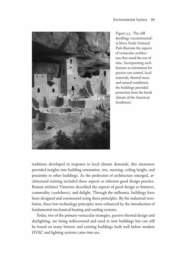
Figure 3.5. The cliff dwellings (reconstructed) at Mesa Verde National Park illustrate the aspects of vernacular architec-ture that stand the test of time. Incorporating such features as orientation for passive sun control, local materials, thermal mass, and natural ventilation, the buildings provided protection from the harsh climate of the American Southwest.
100 Stewardship of the Built Environment
Passive Thermal Design
Passive thermal design relies on the building to mitigate the effects of the lo-cal climate. In the broadest terms, these principles include form and volume, orientation, sun and wind control devices, and the use of thermal mass.
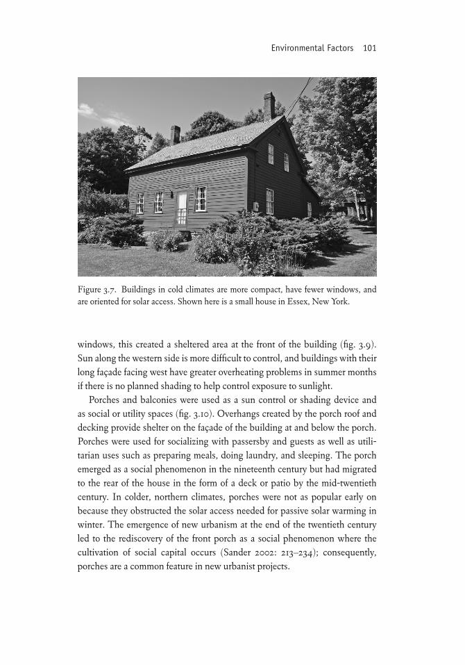
Compact forms were used in cold climates to limit the surface area exposed to cold temperatures (fig. 3.7). Buildings were also built in small clusters or with attached party walls to reduce heat loss. Larger forms and volumes were preferred in hot, humid climates. High ceilings (12–24 feet) allowed warm air to rise out of the occupied zone (fig. 3.8). In smaller houses, shade and cross-ventilation provided relief from the heat.
Orientation relative to the sun’s path was a consideration that played into how a building was located on a site. The daily movement of the sun across the sky provides the greatest solar control along the south façade. As a con-sequence, the longest side of a building was oriented to face south or slightly east of south. When counterposed with the direction for cold northerly winter
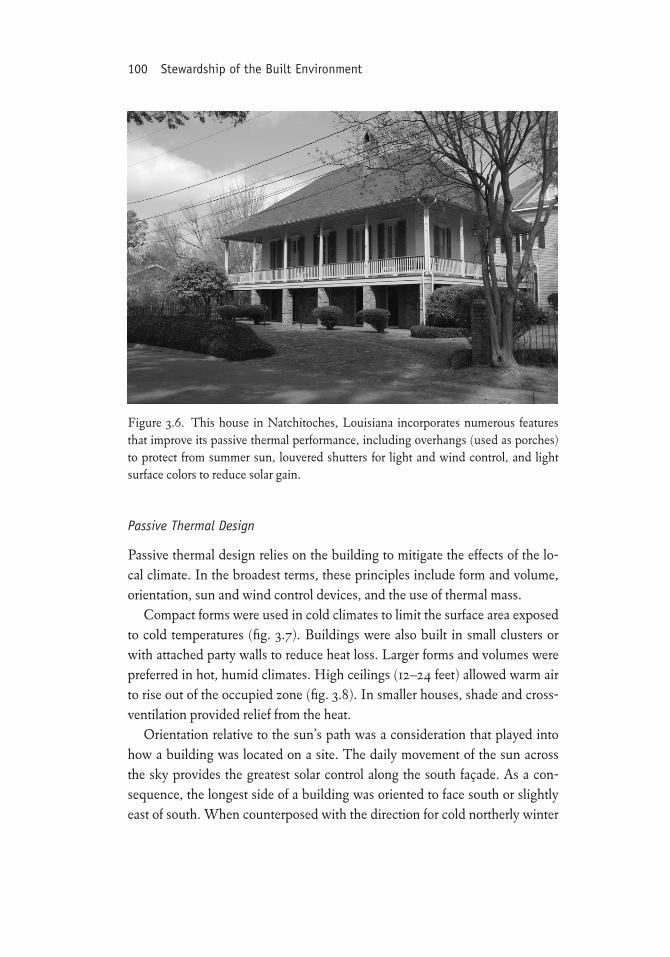
Figure 3.6. This house in Natchitoches, Louisiana incorporates numerous features that improve its passive thermal performance, including overhangs (used as porches) to protect from summer sun, louvered shutters for light and wind control, and light surface colors to reduce solar gain.
Environmental Factors 101
windows, this created a sheltered area at the front of the building (fig. 3.9). Sun along the western side is more difficult to control, and buildings with their long façade facing west have greater overheating problems in summer months if there is no planned shading to help control exposure to sunlight.
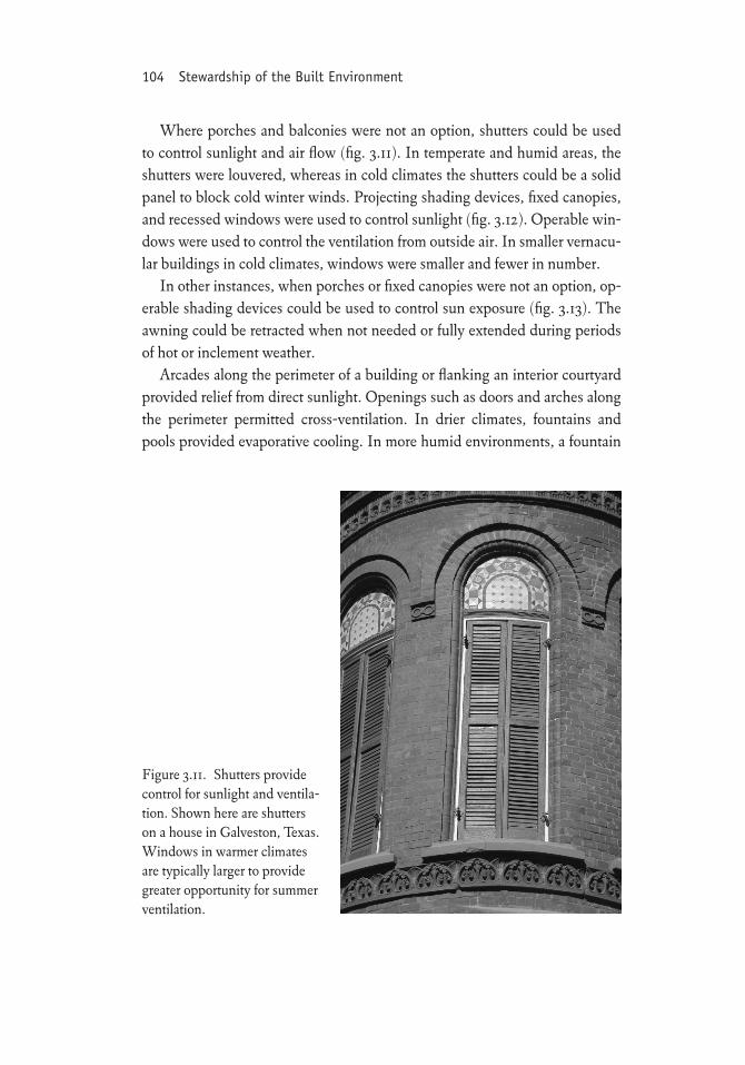
Porches and balconies were used as a sun control or shading device and as social or utility spaces (fig. 3.10). Overhangs created by the porch roof and decking provide shelter on the façade of the building at and below the porch. Porches were used for socializing with passersby and guests as well as utili-tarian uses such as preparing meals, doing laundry, and sleeping. The porch emerged as a social phenomenon in the nineteenth century but had migrated to the rear of the house in the form of a deck or patio by the mid-twentieth century. In colder, northern climates, porches were not as popular early on because they obstructed the solar access needed for passive solar warming in winter. The emergence of new urbanism at the end of the twentieth century led to the rediscovery of the front porch as a social phenomenon where the cultivation of social capital occurs (Sander 2002: 213–234); consequently, porches are a common feature in new urbanist projects.
Figure 3.7. Buildings in cold climates are more compact, have fewer windows, and are oriented for solar access. Shown here is a small house in Essex, New York.
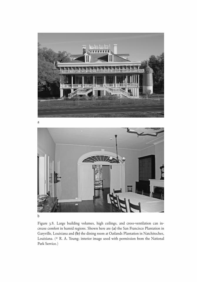
Figure 3.8. Large building volumes, high ceilings, and cross-ventilation can in-crease comfort in humid regions. Shown here are (a) the San Francisco Plantation in Garyville, Louisiana and (b) the dining room at Oatlands Plantation in Natchitoches, Louisiana. (© R. A. Young; interior image used with permission from the National Park Service.)
a
b
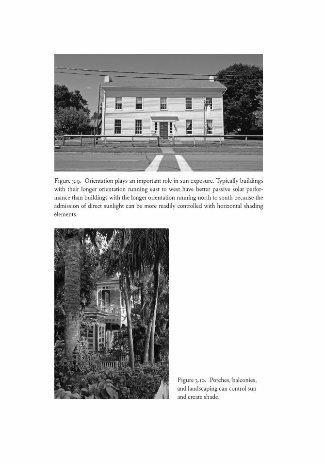
Figure 3.9. Orientation plays an important role in sun exposure. Typically buildings with their longer orientation running east to west have better passive solar perfor-mance than buildings with the longer orientation running north to south because the admission of direct sunlight can be more readily controlled with horizontal shading elements.
Figure 3.10. Porches, balconies, and landscaping can control sun and create shade.
104 Stewardship of the Built Environment
Where porches and balconies were not an option, shutters could be used to control sunlight and air flow (fig. 3.11). In temperate and humid areas, the shutters were louvered, whereas in cold climates the shutters could be a solid panel to block cold winter winds. Projecting shading devices, fixed canopies, and recessed windows were used to control sunlight (fig. 3.12). Operable win-dows were used to control the ventilation from outside air. In smaller vernacu-lar buildings in cold climates, windows were smaller and fewer in number.
In other instances, when porches or fixed canopies were not an option, op-erable shading devices could be used to control sun exposure (fig. 3.13). The awning could be retracted when not needed or fully extended during periods of hot or inclement weather.
Arcades along the perimeter of a building or flanking an interior courtyard provided relief from direct sunlight. Openings such as doors and arches along the perimeter permitted cross-ventilation. In drier climates, fountains and pools provided evaporative cooling. In more humid environments, a fountain
Figure 3.11. Shutters provide control for sunlight and ventila-tion. Shown here are shutters on a house in Galveston, Texas. Windows in warmer climates are typically larger to provide greater opportunity for summer ventilation.
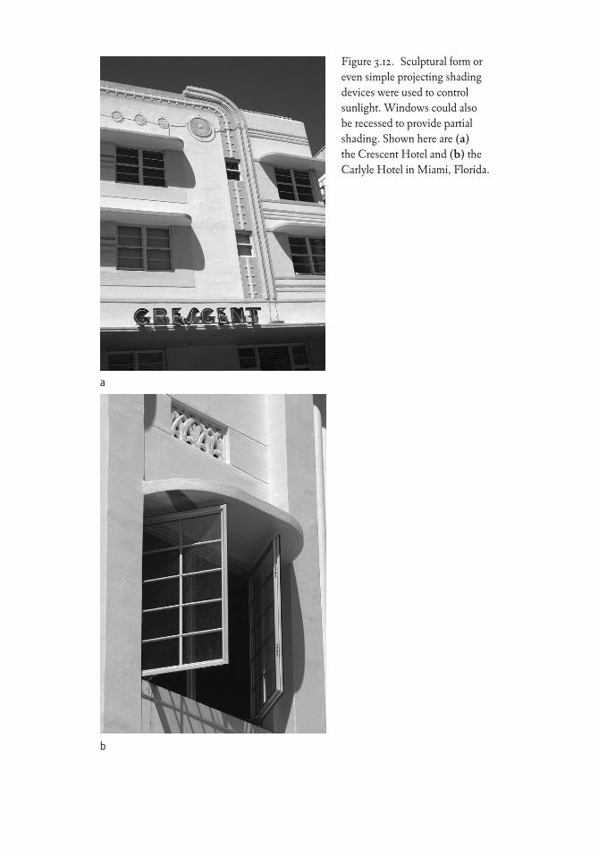
Figure 3.12. Sculptural form or even simple projecting shading devices were used to control sunlight. Windows could also be recessed to provide partial shading. Shown here are (a) the Crescent Hotel and (b) the Carlyle Hotel in Miami, Florida.
a
b
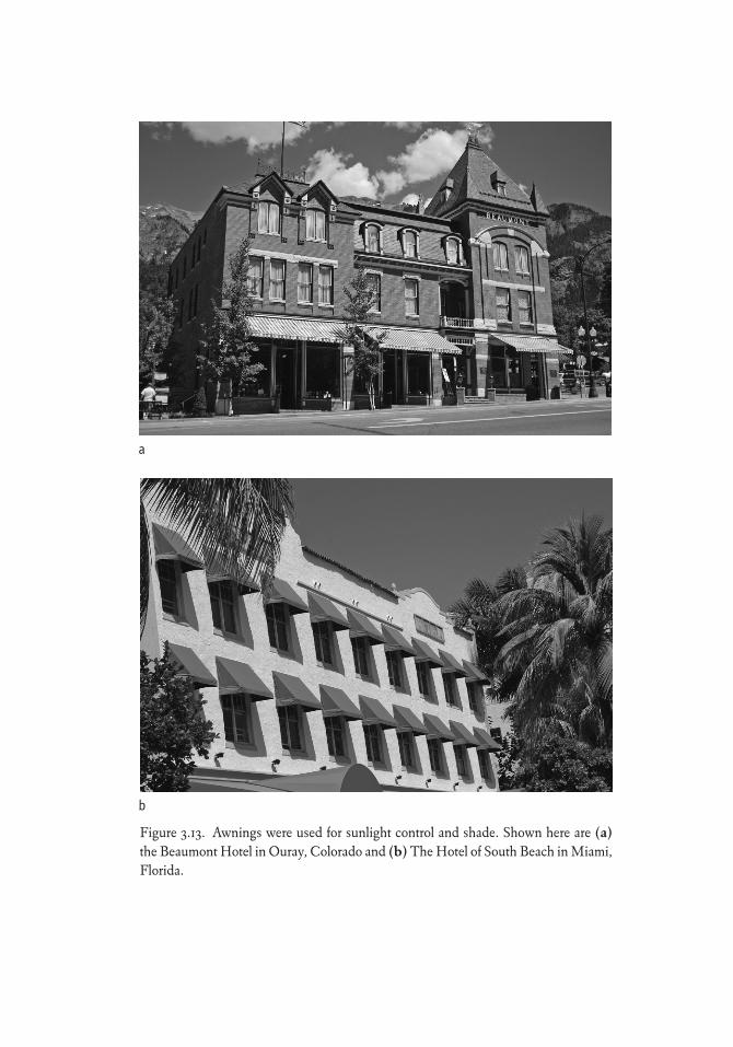
Figure 3.13. Awnings were used for sunlight control and shade. Shown here are (a) the Beaumont Hotel in Ouray, Colorado and (b) The Hotel of South Beach in Miami, Florida.
a
b
Environmental Factors 107
contributes to increased humidity or dampness and is used primarily as orna-ment or for other needs.
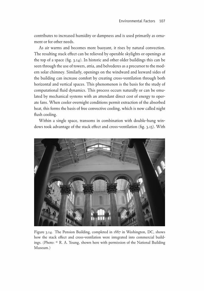
As air warms and becomes more buoyant, it rises by natural convection. The resulting stack effect can be relieved by operable skylights or openings at the top of a space (fig. 3.14). In historic and other older buildings this can be seen through the use of towers, atria, and belvederes as a precursor to the mod-ern solar chimney. Similarly, openings on the windward and leeward sides of the building can increase comfort by creating cross-ventilation through both horizontal and vertical spaces. This phenomenon is the basis for the study of computational fluid dynamics. This process occurs naturally or can be emu-lated by mechanical systems with an attendant direct cost of energy to oper-ate fans. When cooler overnight conditions permit extraction of the absorbed heat, this forms the basis of free convective cooling, which is now called night flush cooling.
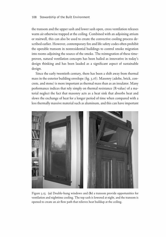
Within a single space, transoms in combination with double-hung win-dows took advantage of the stack effect and cross-ventilation (fig. 3.15). With
Figure 3.14. The Pension Building, completed in 1887 in Washington, DC, shows how the stack effect and cross-ventilation were integrated into commercial build-ings. (Photo: © R. A. Young, shown here with permission of the National Building Museum.)
108 Stewardship of the Built Environment
the transom and the upper sash and lower sash open, cross ventilation releases warm air otherwise trapped at the ceiling. Combined with an adjoining atrium or stairwell, this can also be used to create the convective cooling process de-scribed earlier. However, contemporary fire and life safety codes often prohibit the operable transom in nonresidential buildings to control smoke migration into rooms adjoining the source of the smoke. The reintegration of these time-proven, natural ventilation concepts has been hailed as innovative in today’s design thinking and has been lauded as a significant aspect of sustainable design.
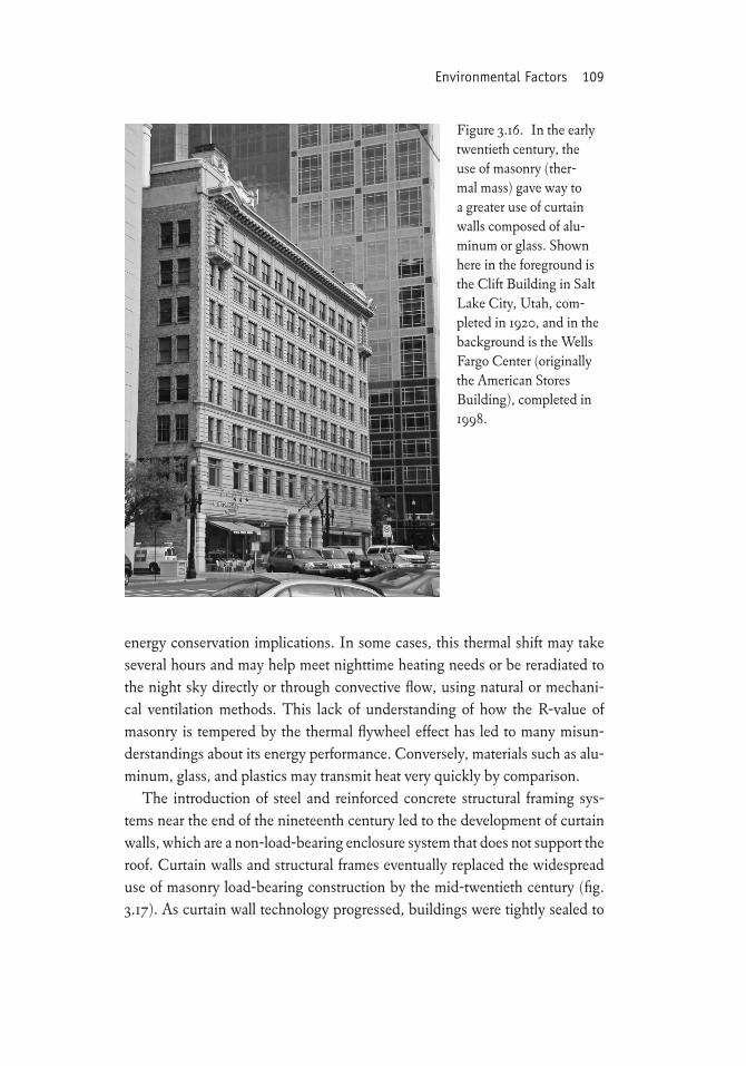
Since the early twentieth century, there has been a shift away from thermal mass in the exterior building envelope (fig. 3.16). Masonry (adobe, brick, con-crete, and stone) is more important as thermal mass than as an insulator. Many performance indices that rely simply on thermal resistance (R-value) of a ma-terial neglect the fact that masonry acts as a heat sink that absorbs heat and slows the exchange of heat for a longer period of time when compared with a less thermally massive material such as aluminum, and this can have important
Figure 3.15. (a) Double-hung windows and (b) a transom provide opportunities for ventilation and nighttime cooling. The top sash is lowered at night, and the transom is opened to create an air flow path that relieves heat buildup at the ceiling.
Environmental Factors 109
energy conservation implications. In some cases, this thermal shift may take several hours and may help meet nighttime heating needs or be reradiated to the night sky directly or through convective flow, using natural or mechani-cal ventilation methods. This lack of understanding of how the R-value of masonry is tempered by the thermal flywheel effect has led to many misun-derstandings about its energy performance. Conversely, materials such as alu-minum, glass, and plastics may transmit heat very quickly by comparison.
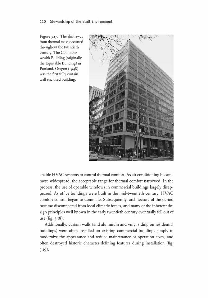
The introduction of steel and reinforced concrete structural framing sys-tems near the end of the nineteenth century led to the development of curtain walls, which are a non-load-bearing enclosure system that does not support the roof. Curtain walls and structural frames eventually replaced the widespread use of masonry load-bearing construction by the mid-twentieth century (fig. 3.17). As curtain wall technology progressed, buildings were tightly sealed to
Figure 3.16. In the early twentieth century, the use of masonry (ther-mal mass) gave way to a greater use of curtain walls composed of alu-minum or glass. Shown here in the foreground is the Clift Building in Salt Lake City, Utah, com-pleted in 1920, and in the background is the Wells Fargo Center (originally the American Stores Building), completed in 1998.
110 Stewardship of the Built Environment
enable HVAC systems to control thermal comfort. As air conditioning became more widespread, the acceptable range for thermal comfort narrowed. In the process, the use of operable windows in commercial buildings largely disap-peared. As office buildings were built in the mid-twentieth century, HVAC comfort control began to dominate. Subsequently, architecture of the period became disconnected from local climatic forces, and many of the inherent de-sign principles well known in the early twentieth century eventually fell out of use (fig. 3.18).
Additionally, curtain walls (and aluminum and vinyl siding on residential buildings) were often installed on existing commercial buildings simply to modernize the appearance and reduce maintenance or operation costs, and often destroyed historic character-defining features during installation (fig. 3.19).
Figure 3.17. The shift away from thermal mass occurred throughout the twentieth century. The Common-wealth Building (originally the Equitable Building) in Portland, Oregon (1948) was the first fully curtain wall enclosed building.
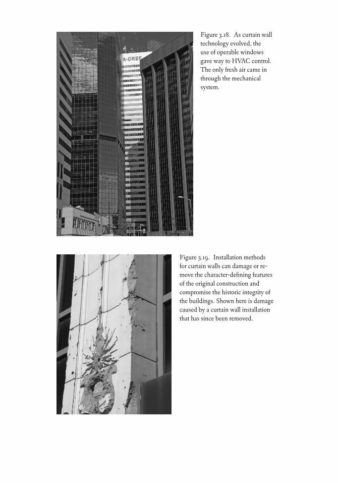
Figure 3.18. As curtain wall technology evolved, the use of operable windows gave way to HVAC control. The only fresh air came in through the mechanical system.
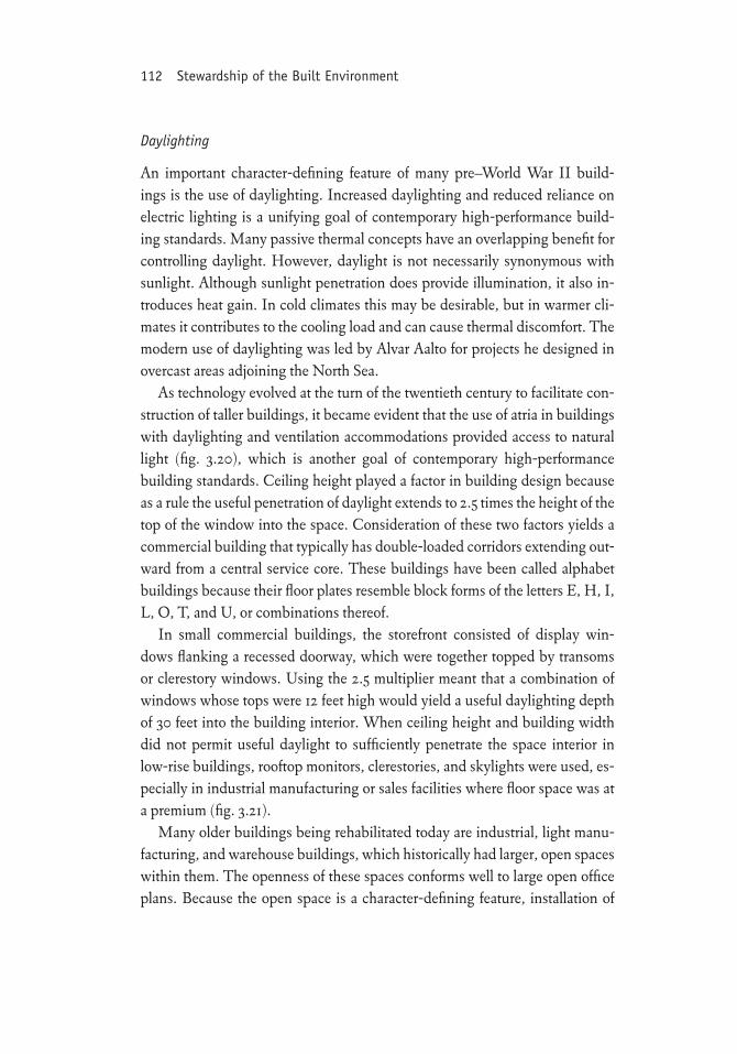
Figure 3.19. Installation methods for curtain walls can damage or re-move the character-defining features of the original construction and compromise the historic integrity of the buildings. Shown here is damage caused by a curtain wall installation that has since been removed.
112 Stewardship of the Built Environment
Daylighting
An important character-defining feature of many pre–World War II build-ings is the use of daylighting. Increased daylighting and reduced reliance on electric lighting is a unifying goal of contemporary high-performance build-ing standards. Many passive thermal concepts have an overlapping benefit for controlling daylight. However, daylight is not necessarily synonymous with sunlight. Although sunlight penetration does provide illumination, it also in-troduces heat gain. In cold climates this may be desirable, but in warmer cli-mates it contributes to the cooling load and can cause thermal discomfort. The modern use of daylighting was led by Alvar Aalto for projects he designed in overcast areas adjoining the North Sea.
As technology evolved at the turn of the twentieth century to facilitate con-struction of taller buildings, it became evident that the use of atria in buildings with daylighting and ventilation accommodations provided access to natural light (fig. 3.20), which is another goal of contemporary high-performance building standards. Ceiling height played a factor in building design because as a rule the useful penetration of daylight extends to 2.5 times the height of the top of the window into the space. Consideration of these two factors yields a commercial building that typically has double-loaded corridors extending out-ward from a central service core. These buildings have been called alphabet buildings because their floor plates resemble block forms of the letters E, H, I, L, O, T, and U, or combinations thereof.
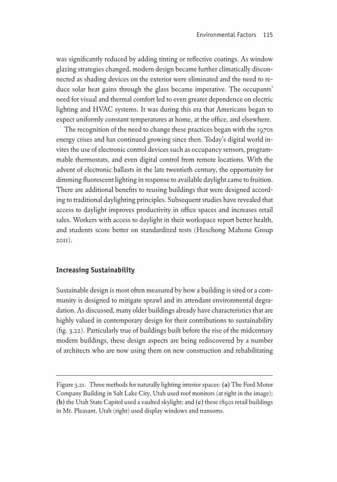
In small commercial buildings, the storefront consisted of display win-dows flanking a recessed doorway, which were together topped by transoms or clerestory windows. Using the 2.5 multiplier meant that a combination of windows whose tops were 12 feet high would yield a useful daylighting depth of 30 feet into the building interior. When ceiling height and building width did not permit useful daylight to sufficiently penetrate the space interior in low-rise buildings, rooftop monitors, clerestories, and skylights were used, es-pecially in industrial manufacturing or sales facilities where floor space was at a premium (fig. 3.21).
Many older buildings being rehabilitated today are industrial, light manu-facturing, and warehouse buildings, which historically had larger, open spaces within them. The openness of these spaces conforms well to large open office plans. Because the open space is a character-defining feature, installation of
Environmental Factors 113
office space is readily accomplished. Conversely, the spaces and historic char-acter-defining features found in double-loaded corridors of alphabet build-ings typically cannot be combined into a single space without jeopardizing tax credits because removing these walls destroys the historic integrity. Rather than create large open floor plans, building owners can create spaces that tar-get smaller business operations that seek smaller spaces or can lease an entire floor.
The introduction of the fluorescent lamp in 1937 changed how buildings were designed. The irregular floor plates gave way to rectangular floor plates lit by continuous rows of fluorescent lighting (with lighting densities approach-ing 5 watts/sf). Daylighting gave way to electric lighting, which eliminated the need for higher ceilings. With the rectangular floor plates, lowered ceilings, and cheap electricity to power them, fluorescent lighting became the norm. To address brightness problems, visible light transmission in glazing products
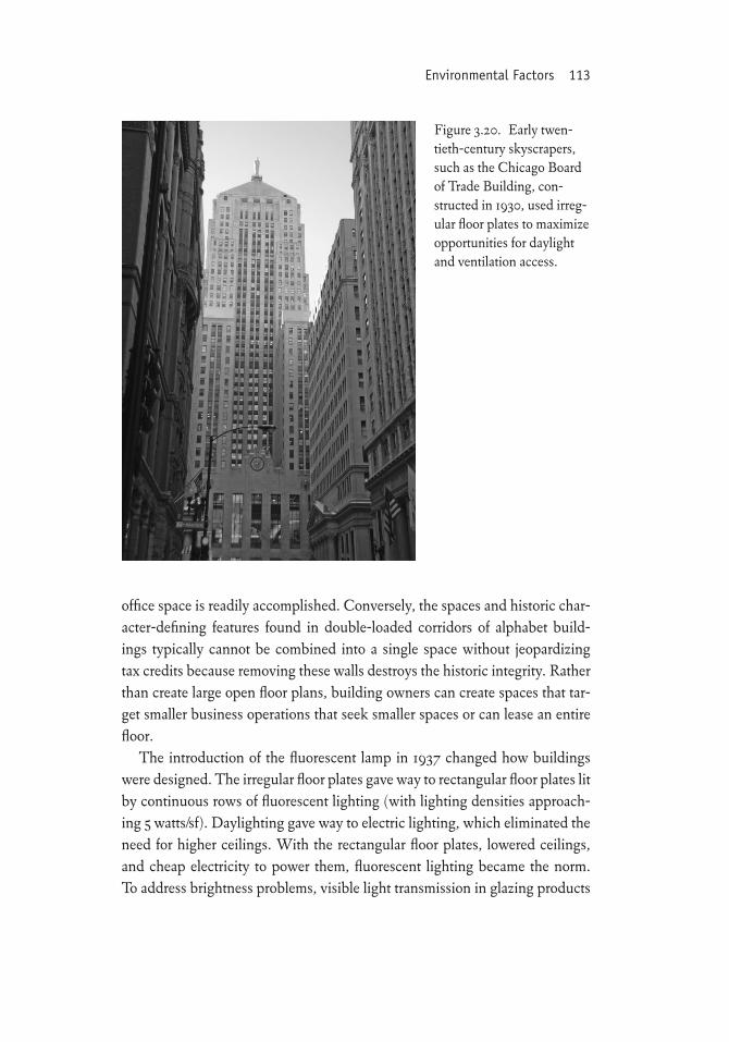
Figure 3.20. Early twen-tieth-century skyscrapers, such as the Chicago Board of Trade Building, con-structed in 1930, used irreg-ular floor plates to maximize opportunities for daylight and ventilation access.
a
b
c
Environmental Factors 115
was significantly reduced by adding tinting or reflective coatings. As window glazing strategies changed, modern design became further climatically discon-nected as shading devices on the exterior were eliminated and the need to re-duce solar heat gains through the glass became imperative. The occupants’ need for visual and thermal comfort led to even greater dependence on electric lighting and HVAC systems. It was during this era that Americans began to expect uniformly constant temperatures at home, at the office, and elsewhere.
The recognition of the need to change these practices began with the 1970s energy crises and has continued growing since then. Today’s digital world in-vites the use of electronic control devices such as occupancy sensors, program-mable thermostats, and even digital control from remote locations. With the advent of electronic ballasts in the late twentieth century, the opportunity for dimming fluorescent lighting in response to available daylight came to fruition. There are additional benefits to reusing buildings that were designed accord-ing to traditional daylighting principles. Subsequent studies have revealed that access to daylight improves productivity in office spaces and increases retail sales. Workers with access to daylight in their workspace report better health, and students score better on standardized tests (Heschong Mahone Group 2011).
Increasing Sustainability
Sustainable design is most often measured by how a building is sited or a com-munity is designed to mitigate sprawl and its attendant environmental degra-dation. As discussed, many older buildings already have characteristics that are highly valued in contemporary design for their contributions to sustainability (fig. 3.22). Particularly true of buildings built before the rise of the midcentury modern buildings, these design aspects are being rediscovered by a number of architects who are now using them on new construction and rehabilitating
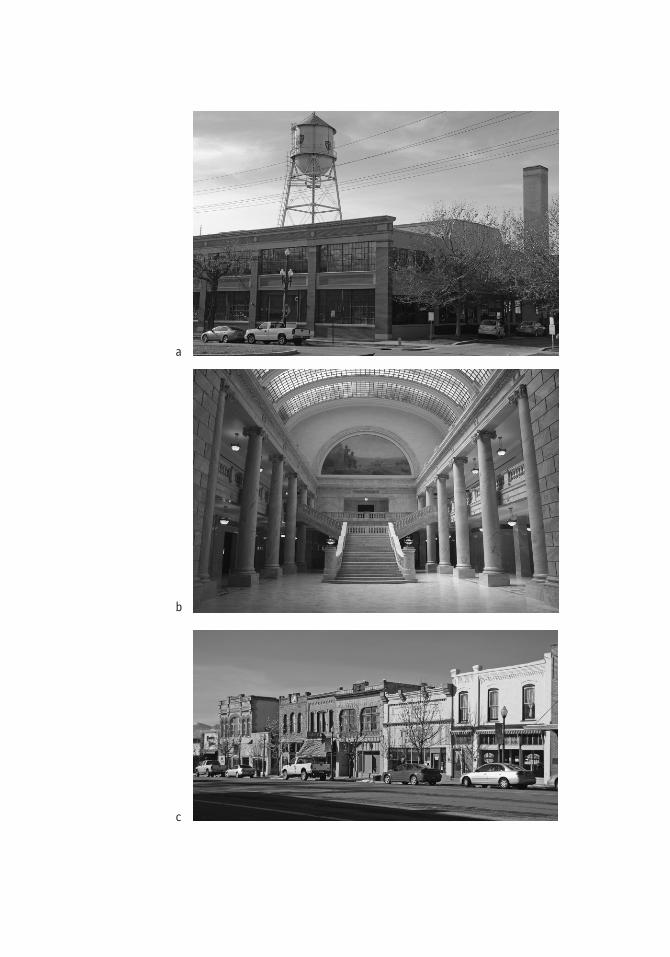
Figure 3.21. Three methods for naturally lighting interior spaces: (a) The Ford Motor Company Building in Salt Lake City, Utah used roof monitors (at right in the image); (b) the Utah State Capitol used a vaulted skylight; and (c) these 1890s retail buildings in Mt. Pleasant, Utah (right) used display windows and transoms.
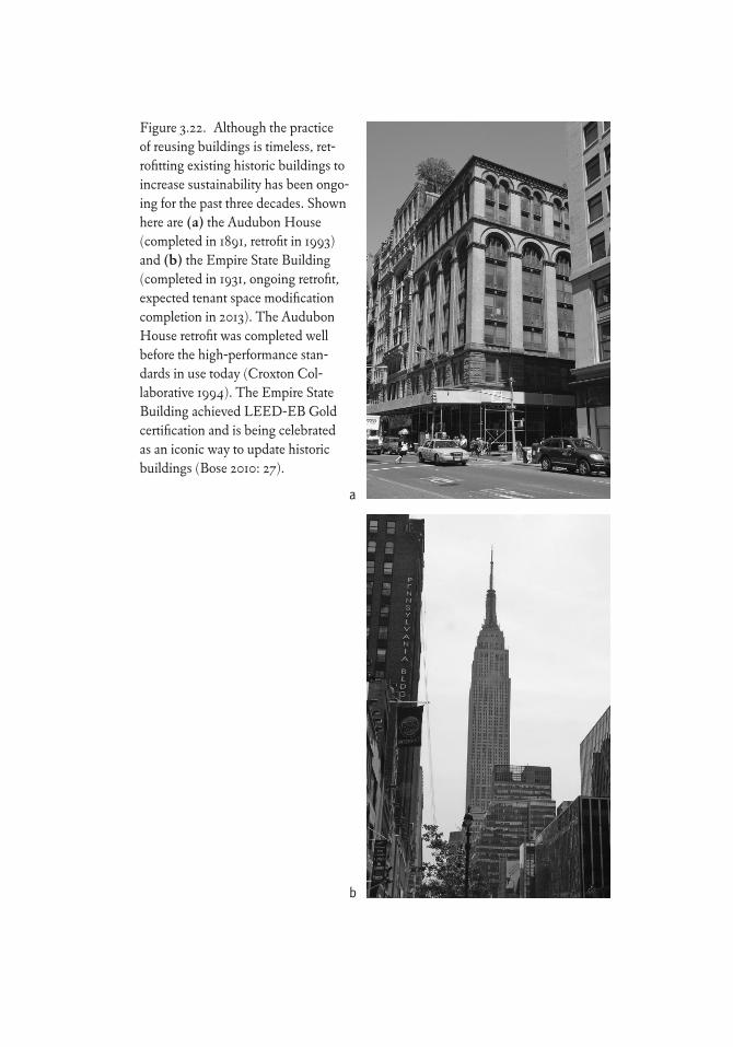
Figure 3.22. Although the practice of reusing buildings is timeless, ret-rofitting existing historic buildings to increase sustainability has been ongo-ing for the past three decades. Shown here are (a) the Audubon House (completed in 1891, retrofit in 1993) and (b) the Empire State Building (completed in 1931, ongoing retrofit, expected tenant space modification completion in 2013). The Audubon House retrofit was completed well before the high-performance stan-dards in use today (Croxton Col-laborative 1994). The Empire State Building achieved LEED-EB Gold certification and is being celebrated as an iconic way to update historic buildings (Bose 2010: 27).
a
b
Environmental Factors 117
them on reuse projects. Two notable examples of this are the Christman Con-struction Headquarters in Lansing, Michigan, which earned the world’s first LEED Triple Platinum status, and the Big D Construction Headquarters in Salt Lake City, Utah, which earned the first LEED Gold status in Utah.
The two primary areas targeted for sustainability upgrades are the build-ing envelope and the mechanical, electrical, and plumbing (MEP) systems’ energy use optimization. At any building scale, there is lively debate about the extent to which envelope modifications (fig. 3.23) compromise authenticity and historic integrity and whether they should be compromised at all.
Building Envelope
Performance of the building envelope (i.e., windows, doors, walls, ceilings, roofs, and floors) can be improved through weatherization and increasing or controlling the admission of natural light. The first concern for many building owners is the efficiency of their windows and how to upgrade them. Inap-propriate replacements (fig. 3.24) have led to much debate between property owners, neighbors, and preservationists. Although there are incentives for energy upgrades through such programs as the American Reinvestment and Recovery Act (Recovery Act), this federally backed program triggers a design review when applied to buildings on or eligible for the NRHP.
Much has been said about the energy savings from replacement windows in a retrofit of an existing building. What often goes unsaid or is misunder-stood is that, because heated air naturally rises, the amount of conductive energy lost through windows is lower than heat lost through infiltration and heat rising into underinsulated attics and roofs. Many building scientists and energy auditors understand this and recommend making rooms less drafty by installing storm windows and weatherstripping, recaulking around openings in the building envelope, and sealing openings leading to or from unheated spaces (e.g., attics, basements, stairwells, mechanical rooms).
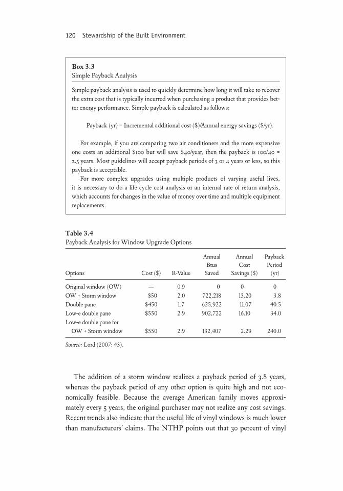
Although window manufacturers extol the virtues of their vinyl-based products, one-for-one replacement of wood windows with more efficient units is not cost-effective in terms of simple payback (box 3.3). A study prepared for the Collingswood Historic District Commission (Lord 2007: 43) showed that the most cost-effective solution was to add a storm window to an existing single-pane window unit (table 3.4). Similar studies demonstrate even longer payback periods for full replacement.
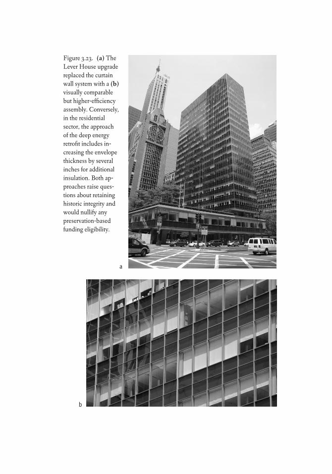
Figure 3.23. (a) The Lever House upgrade replaced the curtain wall system with a (b) visually comparable but higher-efficiency assembly. Conversely, in the residential sector, the approach of the deep energy retrofit includes in-creasing the envelope thickness by several inches for additional insulation. Both ap-proaches raise ques-tions about retaining historic integrity and would nullify any preservation-based funding eligibility.
a
b
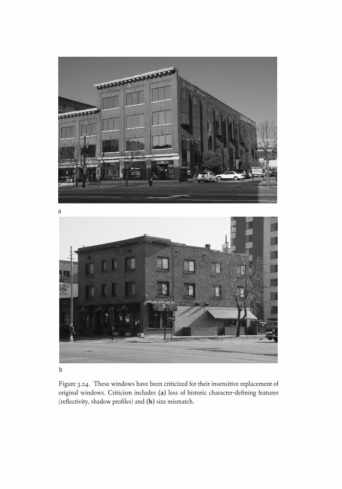
Figure 3.24. These windows have been criticized for their insensitive replacement of original windows. Criticism includes (a) loss of historic character-defining features (reflectivity, shadow profiles) and (b) size mismatch.
a
b
120 Stewardship of the Built Environment
The addition of a storm window realizes a payback period of 3.8 years, whereas the payback period of any other option is quite high and not eco-nomically feasible. Because the average American family moves approxi-mately every 5 years, the original purchaser may not realize any cost savings. Recent trends also indicate that the useful life of vinyl windows is much lower than manufacturers’ claims. The NTHP points out that 30 percent of vinyl
Box 3.3Simple Payback Analysis
Simple payback analysis is used to quickly determine how long it will take to recover the extra cost that is typically incurred when purchasing a product that provides bet-ter energy performance. Simple payback is calculated as follows:
Payback (yr) = Incremental additional cost ($)/Annual energy savings ($/yr).
For example, if you are comparing two air conditioners and the more expensive one costs an additional $100 but will save $40/year, then the payback is 100/40 = 2.5 years. Most guidelines will accept payback periods of 3 or 4 years or less, so this payback is acceptable.
For more complex upgrades using multiple products of varying useful lives, it is necessary to do a life cycle cost analysis or an internal rate of return analysis, which accounts for changes in the value of money over time and multiple equipment replacements.
Table 3.4Payback Analysis for Window Upgrade Options
Annual Annual Payback Btus Cost Period Options Cost ($) R-Value Saved Savings ($) (yr)
Original window (OW) — 0.9 0 0 0OW + Storm window $50 2.0 722,218 13.20 3.8Double pane $450 1.7 625,922 11.07 40.5Low-e double pane $550 2.9 902,722 16.10 34.0Low-e double pane for OW + Storm window $550 2.9 132,407 2.29 240.0
Source: Lord (2007: 43).
Environmental Factors 121
replacement windows are themselves replaced within 10 years (NTHP 2009: 2). Unlike wood windows, vinyl components cannot be repaired when dam-aged and must be completely replaced. Despite the 15- to 20-year warranties offered by the manufacturer, manufacturers of less expensive windows, which would have a lower installed cost and shorter payback periods, may be out of business before the warranty expires. In any of the vinyl replacement window scenarios, the payback exceeds the expected life and probable availability of in-kind replacement.
Repairing wood-framed windows is cost-effective in terms of both first cost and the opportunity to replace subsequently broken or damaged parts (fig. 3.25). When muntin and sash thickness allows, glazing may also be re-placed with individual lites of double-pane glass. If replacement windows are deemed absolutely necessary, consider using a simulated divided lite (SDL) or true divided lite (TDL) window. These pose advantages in that the original muntin bar profiles can be replicated on the exterior and interior faces of the window unit.
Metal sash can corrode and fail, but a more significant drawback is that, in many older types, the frames do not include a thermal break, and heat is con-stantly moving toward cooler temperatures (e.g., outward in winter, inward in summer). In this case, the best option may be to install a replacement sash that includes double-paned glazing and matches the original profile of the frame, sash, and muntins but has been manufactured to include a thermal break that cuts off the heat flow. Another alternative may be to include laminated glass to reduce conductive heat flow and direct solar gain.
When a building is located in a local historic district or when the project is seeking tax credits, the local historic landmarks commission and SHPO can provide guidance on window selection. Installation of inappropriate windows that do not meet the local design guidelines or the Secretary of the Interior’s Guidelines may result in a fine and their replacement at the owner’s expense or the denial of tax credits.
The second major concern for many building owners is the thermal ef-ficiency of the building envelope. Sealing infiltration paths can reduce in-filtration and heat exchange significantly. Likewise, insulating the attic will suppress the natural upward flow of heat. Insulating floors over unheated crawlspaces can keep the floor surface warmer but may have only a nominal effect on energy consumption.
The building walls are the final opportunity for insulation upgrades. The
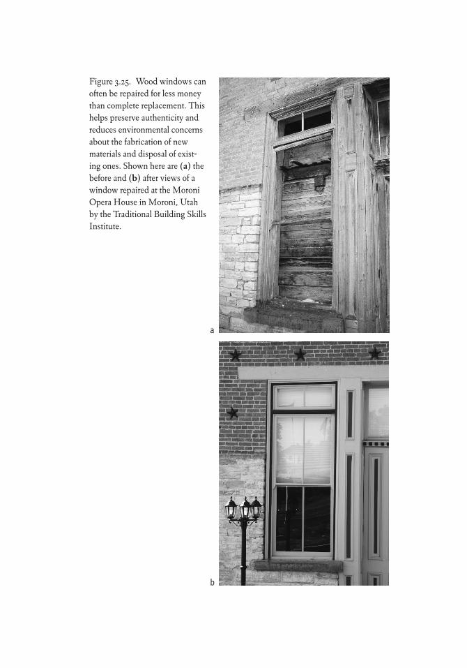
Figure 3.25. Wood windows can often be repaired for less money than complete replacement. This helps preserve authenticity and reduces environmental concerns about the fabrication of new materials and disposal of exist-ing ones. Shown here are (a) the before and (b) after views of a window repaired at the Moroni Opera House in Moroni, Utah by the Traditional Building Skills Institute.
a
b
Environmental Factors 123
insulation could be added in any of three locations: on the interior face, on the exterior face, and within the interior cavity if one exists. Each presents its own array of problems. First, adding the insulation to the interior face encroaches on the occupiable space and destroys the original surface treatments and de-tails. Second, adding insulation to the exterior face, as is done in deep energy retrofits, destroys the exterior appearance in a similar manner as with the inte-rior installation. Third, adding insulation to the cavity can generate numerous problems. Historically, the cavity found in masonry load-bearing walls could actually be a drainage plane situated to allow moisture penetration to drop to drainage openings below. These drainage planes should not be filled in. In all three instances, adding insulation without verifying the suitability of moisture barriers or air barriers can lead to condensation inside the wall that can cause rot, corrosion, mold, and other moisture-related problems.
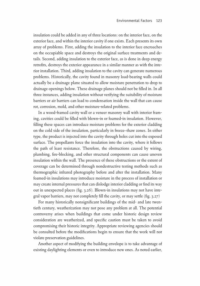
In a wood-framed cavity wall or a veneer masonry wall with interior fram-ing, cavities could be filled with blown-in or foamed-in insulation. However, filling these spaces can introduce moisture problems for the exterior cladding on the cold side of the insulation, particularly in freeze–thaw zones. In either type, the product is injected into the cavity through holes cut into the exposed surface. The propellants force the insulation into the cavity, where it follows the path of least resistance. Therefore, the obstructions caused by wiring, plumbing, fire-blocking, and other structural components can cause uneven insulation within the wall. The presence of these obstructions or the extent of coverage can be determined through nondestructive testing methods such as thermographic infrared photography before and after the installation. Many foamed-in insulations may introduce moisture in the process of installation or may create internal pressures that can dislodge interior cladding or find its way out in unexpected places (fig. 3.26). Blown-in insulations may not have inte-gral vapor barriers, may not completely fill the cavity, or may settle (fig. 3.27)
For many historically nonsignificant buildings of the mid- and late twen-tieth century, weatherization may not pose any problem at all. The potential controversy arises when buildings that come under historic design review consideration are weatherized, and specific caution must be taken to avoid compromising their historic integrity. Appropriate reviewing agencies should be consulted before the modifications begin to ensure that the work will not violate preservation guidelines.
Another aspect of modifying the building envelope is to take advantage of existing daylighting elements or even to introduce new ones. As noted earlier,
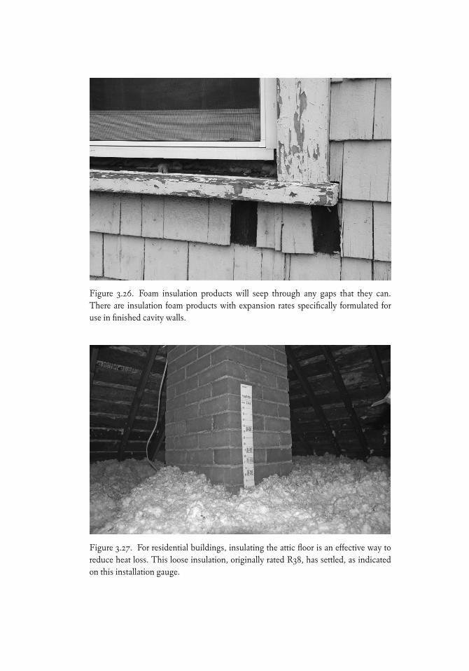
Figure 3.26. Foam insulation products will seep through any gaps that they can. There are insulation foam products with expansion rates specifically formulated for use in finished cavity walls.
Figure 3.27. For residential buildings, insulating the attic floor is an effective way to reduce heat loss. This loose insulation, originally rated R38, has settled, as indicated on this installation gauge.
Environmental Factors 125
building envelope components such as tall windows, transoms, clerestories, and skylights along with high ceilings and atria found in older buildings pro-vide numerous opportunities for daylighting. If not already present, these features can be added. A limiting factor is the amount of sun and brightness controls available for the glazing for buildings of the mid-twentieth-century modern movement. Ceilings in retail buildings that were previously lowered can be removed to increase daylight penetration. Interior clerestories and glass (translucent or transparent) partition walls and flooring may be added to increase daylight penetration without entirely removing the corridor walls. Multiple-floored industrial and warehouse buildings, with their existing sky-lights and open space, foster the creation of atria to penetrate lower floors. For example, removal of floor slabs at the Big D Construction Company Building in Salt Lake City (Young 2008c) still permitted the building to pass the Stan-dards for tax credit work (fig. 3.28).
A variety of sensors, which adjust the amount of electric light according to available daylight, offer another kind of control. With the introduction of elec-tronic ballasts in the 1990s, the combination of daylight sensors and electronic controllers can eliminate or significantly reduce electric lighting. Similarly, an occupancy sensor can activate electric lighting when people are using a space.
Mechanical, Electrical, and Plumbing Systems
In the Standards, MEP equipment (e.g., boilers, chillers, air-handling units) has been protected to the extent that the Standards recommend that original components should be retained and upgraded in place whenever possible. The broader concern relates to physical disruption and visual impact of pip-ing and ductwork, especially on the interior finishes and spatial qualities of historically significant spaces. For buildings with significant public spaces that cannot be adapted to a raised-floor system, care must be taken to route these paths so as not to compromise the visual and physical qualities of those spaces. Concerns also include the terminal devices (e.g., air registers, radiators, light-ing and plumbing fixtures) in these spaces. One specific practice that is not recommended in the Standards is the installation of MEP systems (e.g., me-chanical equipment, solar panels, and photovoltaic panels) in locations visible from a public way. The Standards also recommend that this equipment and distribution networks be located in secondary spaces when possible.
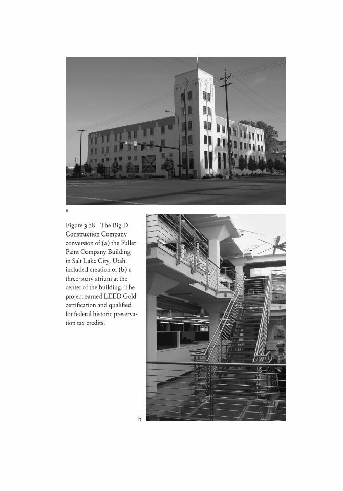
Figure 3.28. The Big D Construction Company conversion of (a) the Fuller Paint Company Building in Salt Lake City, Utah included creation of (b) a three-story atrium at the center of the building. The project earned LEED Gold certification and qualified for federal historic preserva-tion tax credits.
a
b
Environmental Factors 127
Many projects involve replacing less efficient components (e.g., burners, motors, pumps, incandescent lamps) with higher-efficiency versions. Other projects may remove, replace, or relocate portions or all of the equipment and the distribution networks. Additional strategies to improve sustainability per-formance and reduce costs include the following:
• Digital technology overlays• Heat pumps• Raised-floor air supply• Photovoltaic panels• Low-flow plumbing fixtures
One approach to upgrading mechanical and electrical operating systems has been through digital technology control overlays. When systems are con-trolled digitally, any number of control strategies can be used beyond the use of occupancy sensors and timers. Originally individual controllers were on each separate component or subsystem, but by the late twentieth century a centralized control from a remote location was available. Subsequent advances and integration with Internet communications expanded this control to remote mobile locations off-site. This technology has the ability to track usage and operational trends and tune the operating strategies to optimize energy use.
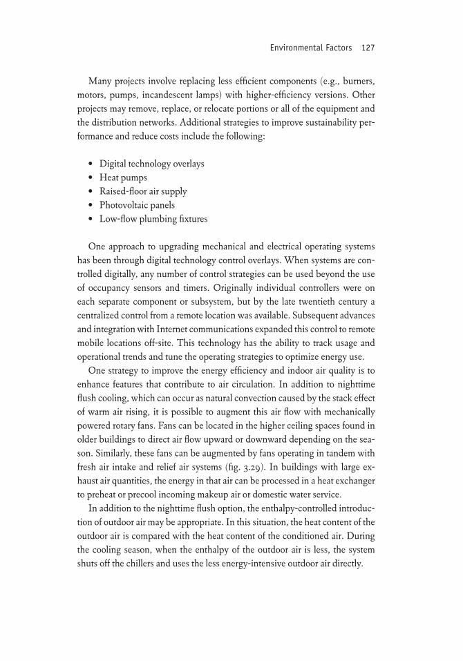
One strategy to improve the energy efficiency and indoor air quality is to enhance features that contribute to air circulation. In addition to nighttime flush cooling, which can occur as natural convection caused by the stack effect of warm air rising, it is possible to augment this air flow with mechanically powered rotary fans. Fans can be located in the higher ceiling spaces found in older buildings to direct air flow upward or downward depending on the sea-son. Similarly, these fans can be augmented by fans operating in tandem with fresh air intake and relief air systems (fig. 3.29). In buildings with large ex-haust air quantities, the energy in that air can be processed in a heat exchanger to preheat or precool incoming makeup air or domestic water service.
In addition to the nighttime flush option, the enthalpy-controlled introduc-tion of outdoor air may be appropriate. In this situation, the heat content of the outdoor air is compared with the heat content of the conditioned air. During the cooling season, when the enthalpy of the outdoor air is less, the system shuts off the chillers and uses the less energy-intensive outdoor air directly.
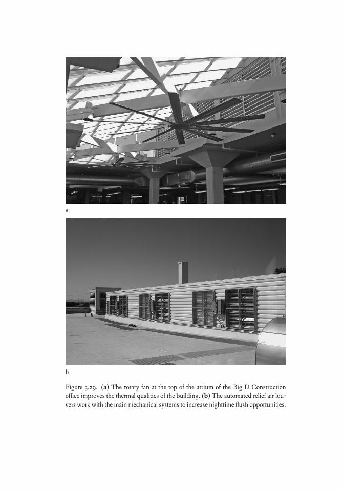
Figure 3.29. (a) The rotary fan at the top of the atrium of the Big D Construction office improves the thermal qualities of the building. (b) The automated relief air lou-vers work with the main mechanical systems to increase nighttime flush opportunities.
a
b
Environmental Factors 129
For residential applications, a programmable thermostat (fig. 3.30) is the starting point for automated control. Modern digital communication control-lers sourced from smart phones and minicomputers are also available to allow homeowners to control their utility systems via remote access.
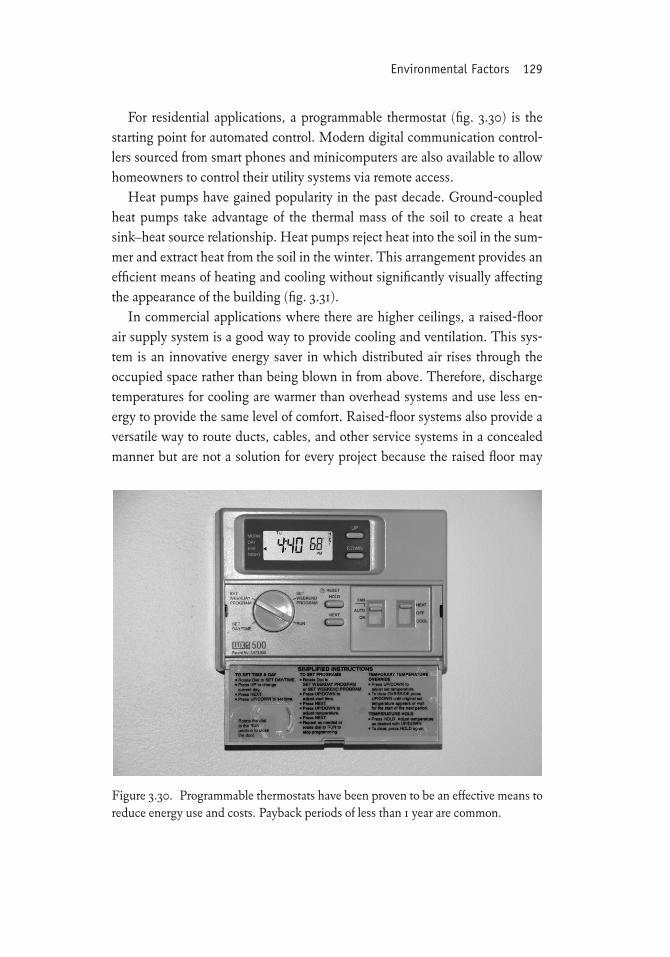
Heat pumps have gained popularity in the past decade. Ground-coupled heat pumps take advantage of the thermal mass of the soil to create a heat sink–heat source relationship. Heat pumps reject heat into the soil in the sum-mer and extract heat from the soil in the winter. This arrangement provides an efficient means of heating and cooling without significantly visually affecting the appearance of the building (fig. 3.31).
In commercial applications where there are higher ceilings, a raised-floor air supply system is a good way to provide cooling and ventilation. This sys-tem is an innovative energy saver in which distributed air rises through the occupied space rather than being blown in from above. Therefore, discharge temperatures for cooling are warmer than overhead systems and use less en-ergy to provide the same level of comfort. Raised-floor systems also provide a versatile way to route ducts, cables, and other service systems in a concealed manner but are not a solution for every project because the raised floor may
Figure 3.30. Programmable thermostats have been proven to be an effective means to reduce energy use and costs. Payback periods of less than 1 year are common.
130 Stewardship of the Built Environment
conflict with existing windowsill and door heights. This approach is success-ful generally in industrial and warehouse reuse projects but has limited ap-plication in alphabet buildings because of the expense of installing ramps or adjusting doors and stairways.
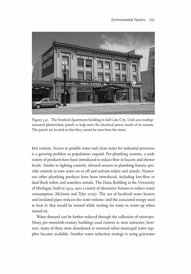
Photovoltaics (and solar panels) have created quite a controversy in historic districts because of their appearance on primary façades or roofs viewed from a public way. When carefully located out of public view, they provide the de-sired power and thermal energy without visual disruption (fig. 3.32). Many retrofit projects have incorporated off-site power production (e.g., subscribing to wind energy programs offered by local utilities) to meet renewable energy use targets and have used this opportunity to meet requirements of programs such as LEED without constructing on-site equipment. The district energy strategy championed by the Preservation Green Lab noted in chapter 2 is an-other approach to reducing visual impact of these installations.
Water conservation is a fast-emerging sustainability concern in the twenty-
Figure 3.31. The Major Downey House in Salt Lake City, Utah uses an innovative heat exchange system. Although ground-coupled heat pumps are gaining widespread acceptance nationwide, the heat pump at the Major Downey House exchanges heat with the municipal sewer line adjoining the property.
Environmental Factors 131
first century. Access to potable water and clean water for industrial processes is a growing problem as populations expand. For plumbing systems, a wide variety of products have been introduced to reduce flow in faucets and shower heads. Similar to lighting controls, infrared sensors in plumbing fixtures pro-vide controls to turn water on or off and activate toilets and urinals. Numer-ous other plumbing products have been introduced, including low-flow or dual-flush toilets and waterless urinals. The Dana Building at the University of Michigan, built in 1903, uses a variety of alternative fixtures to reduce water consumption (McInnis and Tyler 2005). The use of localized water heaters and insulated pipes reduces the water volume (and the associated energy used to heat it) that would be wasted while waiting for water to warm up when turned on.
Water demand can be further reduced through the collection of rainwater. Many pre-twentieth-century buildings used cisterns to store rainwater; how-ever, many of these were abandoned or removed when municipal water sup-plies became available. Another water reduction strategy is using graywater
Figure 3.32. The Stratford Apartments building in Salt Lake City, Utah uses rooftop-mounted photovoltaic panels to help meet the electrical power needs of its tenants. The panels are located so that they cannot be seen from the street.
132 Stewardship of the Built Environment
systems to recover water from sinks and showers for reuse in toilets and other nonculinary purposes. Some local ordinances do not allow use of these two strategies, however, so they are not appropriate for every building.
Building Codes
Building codes are created primarily with the needs of new construction in mind. Many code revisions come about in reaction to building failures, fire di-sasters, new technologies, and construction practices. Although the intention is to make the built environment safer and more sustainable, their adoption often creates unintended consequences. It is not unexpected, then, that the re-cent sustainability quantification methods, like most other industry practices, initially and primarily dealt with new construction. This approach has left pro-ponents of preserving historic buildings and adaptively using other existing buildings to their own devices when it comes to convincing others about the viability of their efforts. These factors also have created some unintended con-sequences that weaken efforts toward stewardship of the built environment and the overall sustainability of a community.
As efforts to make buildings more energy efficient in the 1980s became part of the professional design community’s service offerings, early standards such as ANSI/ASHRAE/IESNA Standard 90 (ASHRAE 90) were integrated into a variety of regionally based codes for new construction. Typically, the success of energy efficiency upgrades is expressed in terms of how much below the minimum ASHRAE 90 compliance level the building performance achieves. For example, a building energy consumption level that is 20 percent below the ASHRAE 90 standard uses 20 percent less than the accepted amount of energy usage for that type of building. Although this standard can be fairly benign toward existing buildings, the further reduction of energy targets may conflict with preservation projects because construction practices geared to-ward new construction can conflict with the intention to retain historic char-acter-defining features.
With the introduction and adoption of the International Building Code (IBC) in 2000, regionally administered codes were discontinued. The IBC still looks primarily at new construction, which has hindered interpretation of design intentions in existing buildings. To address this oversight, the In-ternational Existing Building Code (IEBC) has been developed as a model
Environmental Factors 133
code for communities to use in fostering a more flexible interpretation of how existing buildings can be made to perform as needed in contemporary society. Unfortunately, the IEBC has not been widely adopted or used.
In 2009, the International Codes Council announced plans to develop the International Green Construction Code (IGCC), which is a model code “fo-cused on new and existing commercial buildings addressing green building design and performance” (International Codes Council 2011). With prece-dence models from smart codes that have been developed in the past decade, coupled with the efforts of organizations such as the Preservation Green Lab and its outcome-based code program, it is hoped that this code will accom-modate performance goals that are friendlier to preservation and reuse projects than in the past.
In addition to using the IBC, many states and municipalities have devel-oped high-performance building standards and smart codes. A few include existing buildings, but many look specifically at new construction. They largely leave the issues affecting reuse and preservation open for interpretation through the lens of new construction. This freedom of interpretation has not made preservation and reuse seem more attractive, however. Without direct guidelines, many developers, lenders, contractors, and designers operate only in the realm of new buildings and cannot or will not take on the “risk” of reus-ing a building.
Accessibility, Life Safety, and Security
Technology impacts on sustainability encompass a broad range of consider-ations, much broader than simple energy efficiency. These include accessibility, life safety, and security; urban heat island mitigation; and the environmental im-pacts of creating more sprawl versus repopulating central cities (i.e., increas-ing population density).
Similar to new mechanical, electrical, and plumbing system insertions, preservation of character-defining features can present a challenge when a public building is upgraded to meet Americans with Disabilities Act (ADA) compliance and life safety and security needs, which are also facets of social sustainability. In Preservation Brief 32, Making Historic Buildings Accessible, Jester and Park (1993) describe the various aspects of creating accessibility while respecting the historic significance of the building:
134 Stewardship of the Built Environment
• Make the main or a prominent public entrance and primary public spaces accessible, including a path to the entrance.
• Provide access to goods, services, and programs.• Provide accessible restroom facilities.• Create access to amenities and secondary spaces.
As the historic significance of the building increases, so does the level of attention to sensitively inserting ADA, life safety, and security measures into the primary (public) spaces. The general approach for these enhancements (e.g., elevator upgrades, emergency egress stairs) has been to locate them in secondary spaces adjoining the primary ones, as is often done with new MEP systems as well. The Whole Building Design Guide has established a set of ap-proaches to consider when incorporating new life safety and security measures into an existing building (box 3.4). Although these are intended for histori-cally significant buildings, they can also be sensitive design considerations for rehabilitating or adaptively reusing a nonhistoric building.
In accordance with the Standards, the design of any of these new features should be differentiated from the historic property, and the modifications should be on scale with the historic property, visually compatible, and revers-ible. Reversibility is a key component of any modifications or repairs to his-toric buildings. Ongoing changes in technology introduce new installation methods, systems, and materials to preservation practice. The Standards do not recommend using any installation method, system, or material that de-stroys the existing character-defining features or makes it impossible to reverse the installation process and return the character-defining feature to its previ-ous condition.
Urban Heat Islands
The built environment lends itself to forming urban heat islands where con-centrations of buildings and paved surfaces collect solar energy and alter the local microclimate to be warmer and drier than surrounding suburban and ru-ral areas. In the 1990s, the National Aeronautics and Space Administration conducted flyovers to measure the impact of the built environment on tem-perature. The resulting thermographic images confirmed the actual thermal impacts of heat islands, which has subsequently fostered the introduction of
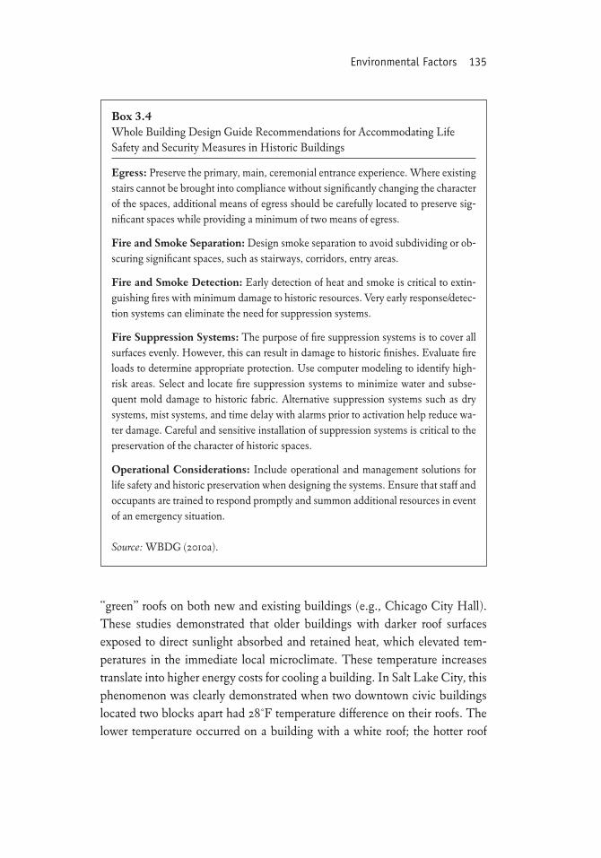
Environmental Factors 135
“green” roofs on both new and existing buildings (e.g., Chicago City Hall). These studies demonstrated that older buildings with darker roof surfaces exposed to direct sunlight absorbed and retained heat, which elevated tem-peratures in the immediate local microclimate. These temperature increases translate into higher energy costs for cooling a building. In Salt Lake City, this phenomenon was clearly demonstrated when two downtown civic buildings located two blocks apart had 28°F temperature difference on their roofs. The lower temperature occurred on a building with a white roof; the hotter roof
Box 3.4Whole Building Design Guide Recommendations for Accommodating Life Safety and Security Measures in Historic Buildings
Egress: Preserve the primary, main, ceremonial entrance experience. Where existing stairs cannot be brought into compliance without significantly changing the character of the spaces, additional means of egress should be carefully located to preserve sig-nificant spaces while providing a minimum of two means of egress.
Fire and Smoke Separation: Design smoke separation to avoid subdividing or ob-scuring significant spaces, such as stairways, corridors, entry areas.
Fire and Smoke Detection: Early detection of heat and smoke is critical to extin-guishing fires with minimum damage to historic resources. Very early response/detec-tion systems can eliminate the need for suppression systems.
Fire Suppression Systems: The purpose of fire suppression systems is to cover all surfaces evenly. However, this can result in damage to historic finishes. Evaluate fire loads to determine appropriate protection. Use computer modeling to identify high-risk areas. Select and locate fire suppression systems to minimize water and subse-quent mold damage to historic fabric. Alternative suppression systems such as dry systems, mist systems, and time delay with alarms prior to activation help reduce wa-ter damage. Careful and sensitive installation of suppression systems is critical to the preservation of the character of historic spaces.
Operational Considerations: Include operational and management solutions for life safety and historic preservation when designing the systems. Ensure that staff and occupants are trained to respond promptly and summon additional resources in event of an emergency situation.
Source: WBDG (2010a).
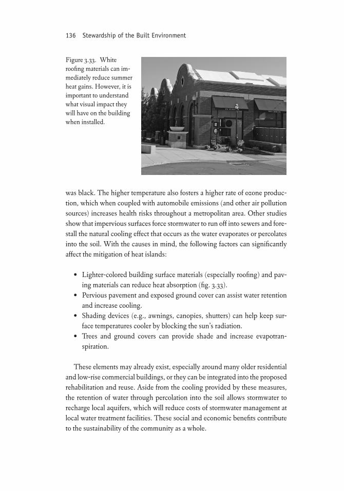
136 Stewardship of the Built Environment
was black. The higher temperature also fosters a higher rate of ozone produc-tion, which when coupled with automobile emissions (and other air pollution sources) increases health risks throughout a metropolitan area. Other studies show that impervious surfaces force stormwater to run off into sewers and fore-stall the natural cooling effect that occurs as the water evaporates or percolates into the soil. With the causes in mind, the following factors can significantly affect the mitigation of heat islands:
• Lighter-colored building surface materials (especially roofing) and pav-ing materials can reduce heat absorption (fig. 3.33).
• Pervious pavement and exposed ground cover can assist water retention and increase cooling.
• Shading devices (e.g., awnings, canopies, shutters) can help keep sur-face temperatures cooler by blocking the sun’s radiation.
• Trees and ground covers can provide shade and increase evapotran- spiration.
These elements may already exist, especially around many older residential and low-rise commercial buildings, or they can be integrated into the proposed rehabilitation and reuse. Aside from the cooling provided by these measures, the retention of water through percolation into the soil allows stormwater to recharge local aquifers, which will reduce costs of stormwater management at local water treatment facilities. These social and economic benefits contribute to the sustainability of the community as a whole.
Figure 3.33. White roofing materials can im-mediately reduce summer heat gains. However, it is important to understand what visual impact they will have on the building when installed.
Recommended