TF 2500 BGA Rework Station Operation and Maintenance Manual
Manual Number 5050-0544
Rev B
System Operations Manual
www.paceworldwide.com Page 2 of 44
Table of Contents
Packing Contents, Standard Items ..................................3 Specifications ..................................................................3 Parts Identification ...........................................................4 Safety Information ...........................................................6 Features ..........................................................................6 Set-Up .............................................................................7
System Connections.............................................7 Start up .................................................................7 Inserting/ changing vacuum pick...........................8 Inserting/changing nozzle .....................................8 Set up screen features..........................................9 Alignment screen features ..................................10 Production screen features .................................11 Production Mode Record Manager features .......12 Profile development screen features ..................13 Development Mode Profile Manager ..................15 Inspection screen features..................................17 Prism Calibration ................................................18
Operation.......................................................................20 Production...........................................................20 Component removal............................................23 Profile development installation procedure .........24
Temperature, Time, and Airflow Control........................26 Available Nozzles, Accessories, and Optional Items.....26 Maintenance..................................................................26 Heater Replacement......................................................27 Adjustments and Alignments .........................................38 Regulation .....................................................................42 Service and Warranty ....................................................43
System Operations Manual
www.paceworldwide.com Page 3 of 44
1. Packing Contents, Standard Items Description Part Number TF 2500 8007-0430 (120V) 8007-0431 (230V) PC 6000-0233
Keyboard - Mouse -
Monitor 1107-0032 Vacuum Pick 1272-0005-P1 Vacuum Pick Kit 6993-0060 Suction Cups 6993-0202-P1 Alignment Board 4018-0100-P1 Mounting Platform Stencil 1321-0725 Mounting Platform Flux Dip 1321-0735 Hot Grip Removal Pad 1100-0307 Thermocouples (4) 1340-0174-P1 Hex Wrench Kit 6016-0034 Power Cord 1332-0224 Video Cable 3008-0168
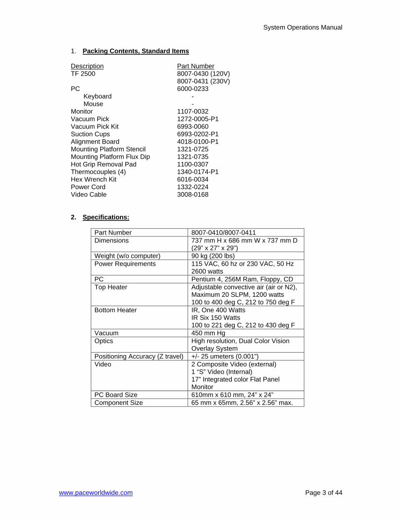
2. Specifications:
Part Number 8007-0410/8007-0411 Dimensions 737 mm H x 686 mm W x 737 mm D
(29” x 27” x 29”) Weight (w/o computer) 90 kg (200 lbs) Power Requirements 115 VAC, 60 hz or 230 VAC, 50 Hz
2600 watts PC Pentium 4, 256M Ram, Floppy, CD Top Heater Adjustable convective air (air or N2),
Maximum 20 SLPM, 1200 watts 100 to 400 deg C, 212 to 750 deg F
Bottom Heater IR, One 400 Watts IR Six 150 Watts 100 to 221 deg C, 212 to 430 deg F
Vacuum 450 mm Hg Optics High resolution, Dual Color Vision
Overlay System Positioning Accuracy (Z travel) +/- 25 umeters (0.001”) Video 2 Composite Video (external)
1 “S” Video (Internal) 17” Integrated color Flat Panel Monitor
PC Board Size 610mm x 610 mm, 24” x 24” Component Size 65 mm x 65mm, 2.56” x 2.56” max.
System Operations Manual
www.paceworldwide.com Page 4 of 44
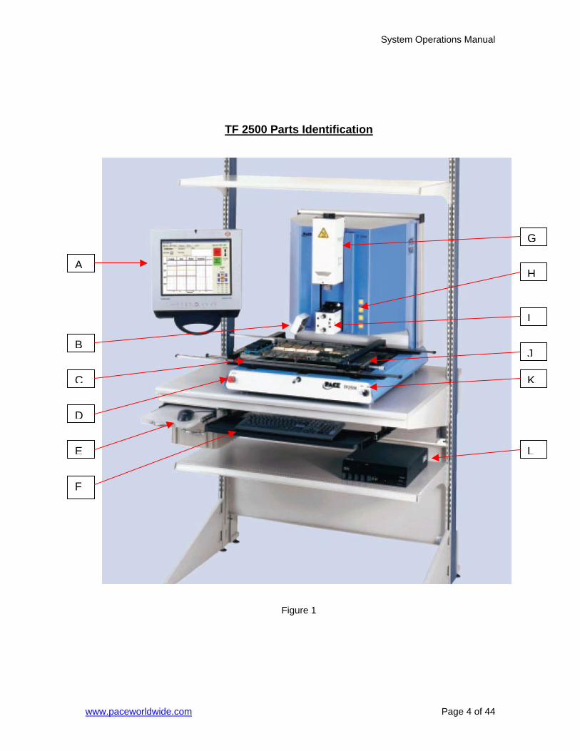
TF 2500 Parts Identification
Figure 1
B
C
D
F
G
HA
I
J
K
LE

System Operations Manual
www.paceworldwide.com Page 5 of 44
A. LCD Display Monitor Displays PC Software B. Cooling Fan The component and PCB are cooled by the cooling fan, which can be set to activate automatically after the
reflow cycle is complete or operated manually. C. Board Holder The board holder is fully adjustable in the X direction
only. Fine adjustment of both the X and Y direction is achieved by using the adjusting knobs on the end of the holder for X and on the front of the machine for Y.
The right side of the holder is spring loaded to hold the PCB securely.
D. Emergency Off Switch In case an emergency shut down is necessary, press this button.
E. Mouse Used to enter information into software. F. Keyboard Used to enter information into software. G. Reflow Head Contains the top-side heater and moves up and down
via an electric motor that is controlled through the software. The reflow head is clutched to prevent excessive downward force from being applied.
H. Sensor Input The sensor inputs are K-type thermo-couples. Measured temperatures are displayed through the PC
software in real time for use in making profile graphs. G. Optics Housing Contains the camera and beam splitter (prism). The
housing is retractable and should be kept in the retracted position when not in use. The lights for the optics will turn on/off automatically when the housing is extended/retracted.
J. Bottom Side Heater Used to warm the PCB from the underside. It is an IR type heating source.
K. On / Off Switch Used to turn the system on or off. When turning off the system, always turn off the PC using the Windows interface first.
L. Computer Brain of the system. Contains the TF 2500 software.
System Operations Manual
www.paceworldwide.com Page 6 of 44
3. Safety Information
a. Do not contact the Heater or its peripheral parts during operation. b. Once turned off, let the unit cool completely before contacting. c. When using fluxes, use fume extraction equipment or use in a well-ventilated
area to minimize operator exposure to fumes. d. Do not use near combustible vapors. e. Do not leave the equipment unattended when in use. f. Do not open rear panel without disconnecting power cable. g. Do not lift or lean on PCB holder rails.
4. Features
a. The TF 2500 is ideal for post assembly rework, repair, and low volume/short run production operations. The TF 2500 can remove and install PBGAs, CSPs, FCs, LGAs, LCC’s and other SMDs.
b. Featuring unparalleled thermal performance, the TF 2500’s flexibility and state of the art process software means no other system is easier to use. The TF 2500 is a PC driven, semi-automated system that requires a Pentium ® 4 PC featuring Windows XP® Professional Operating System. The unique standard software package offers much more than just an operator interface. TF 2500’s advanced vision and placement system is highly accurate and can quickly magnify even the smallest components for easy alignment. TF 2500 uses a combination of convective top heating coupled with powerful IR bottom heating for an effective, repeatable heating process.
c. Economical and easy to use, the TF2500 Rework System delivers high-end BGA/CSP functionality, moving far beyond expensive, bulky rework machines by offering unparalleled performance at an affordable price.
d. REFLOW FUNCTION
i. Unequalled programmability and process control ensures successful, repeatable installations.
ii. The powerful and responsive 1200 Watt top heater, with closed loop temperature control, coupled with proven TF 1500 nozzle design ensures uniform temperature distribution when heating.
iii. High power bottom heaters allow for successful and repeatable reflow at safe, low temperatures.
iv. Profiles are programmed through the PC software. v. Creating the perfect profile is easy with real time adjustment of profile
parameters through the PC. vi. Store and recall an infinite number of profiles. vii. Two pre-defined profiles for use as baselines when developing custom
profiles are included. viii. Self contained, no external air supply or vacuum connections required.
Can also be used with N2 from external source. ix. Semi-automated, motorized reflow head. x. Four thermo-couple sensor inputs ensure successful profile development
and monitoring. xi. External fan to cool PCB and component to below solder melt
temperatures after reflow.
e. ALIGNMENT AND PLACEMENT FUNCTION i. The component is held by a precision vacuum placement pick, which is
located within the heater assembly.
System Operations Manual
www.paceworldwide.com Page 7 of 44
ii. High resolution Dual Color Vision Overlay System (VOS) with color camera and dichroic prism. VOS does not require routine calibration, eliminating costly downtime and operator frustration.
iii. Color Camera with 300x zoom capability, featuring auto-focus zoom. iv. Lighting system uses “Ultra Bright” Red and Blue LEDs for maximum
contrast of lands and solder balls on component. v. Independent lighting controls for component and PCB to maximize
overlay contrast. vi. Retractable optics housing protects VOS from dirt and contamination. vii. Precise micrometer adjustment for X, and Y axis with Theta adjustment
ensures placement accuracy. viii. High-flow vacuum pick holds component securely. ix. Images are viewed through the PC in standard or full screen viewing
options.
f. PRE-HEAT FUNCTION AND BOARD HOLDER i. Fully adjustable, precision, spring loaded board holder with top or bottom
PCB registration. Precise micrometer adjustment for X and Y adjustment ensures placement accuracy for repeatability.
ii. Rugged, stable board platform to hold and support the PCB. iii. Unique board holding fixtures that are able to hold very small and odd
shaped PCBs. iv. Board supports are standard with the system. v. Integrated, powerful, IR pre-heater with closed loop temperature control
ensures process integrity by delivering heat evenly, time after time.
5. Set-Up
a. System Connections i. Monitor
1. Connect power cord. 2. Connect video cable to the 9-pin connector on the Frame
Grabber Card. ii. Keyboard – connect cable to computer. iii. Mouse – connect cable to computer. iv. Connect cables between PC and back of TF 2500 according to labels. v. Connect video cable (3 wire - 1 S video and 2 BNC terminations) to PC
and connect the S video cable to S-video output on TF 2500. vi. Connect power cords to TF 2500 and PC.
b. Start up
i. Verify the on circuit breaker on back of unit is in the “ON” position. ii. Verify Emergency Stop (Big Red Button on Front of Unit) is not engaged.
Turn to release. iii. Turn on power switch
on front of system. System will beep.
iv. Turn on computer. v. Turn on monitor. vi. Mouse click on TF 2500
icon. vii. Read and accept
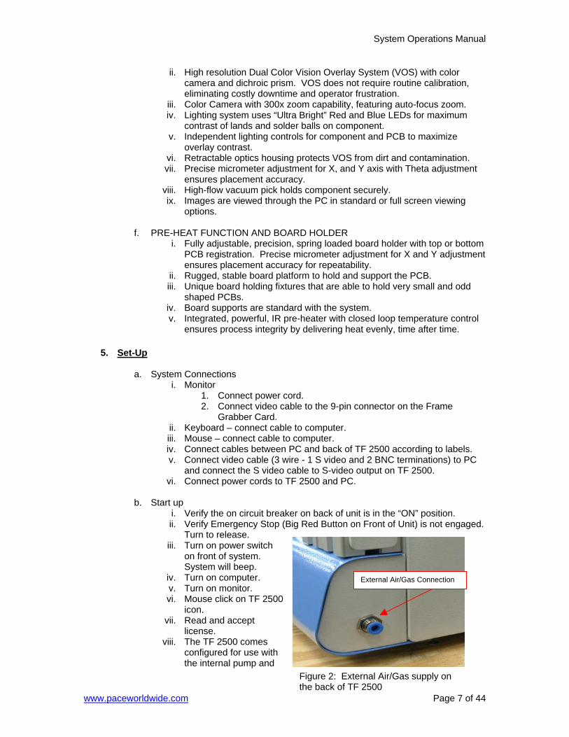
license. viii. The TF 2500 comes
configured for use with the internal pump and
Figure 2: External Air/Gas supply on the back of TF 2500
External Air/Gas Connection
System Operations Manual
www.paceworldwide.com Page 8 of 44
can be configured to use an external air/gas (N2) source. Go to the set-up page in the software to select the desired air source (internal pump or external N2).
Warning: Do not run unit in N2 mode unless N2 supply is connected and turned on. (Figure 2) N2 must be regulated down to 15 PSI before connecting to TF 2500.
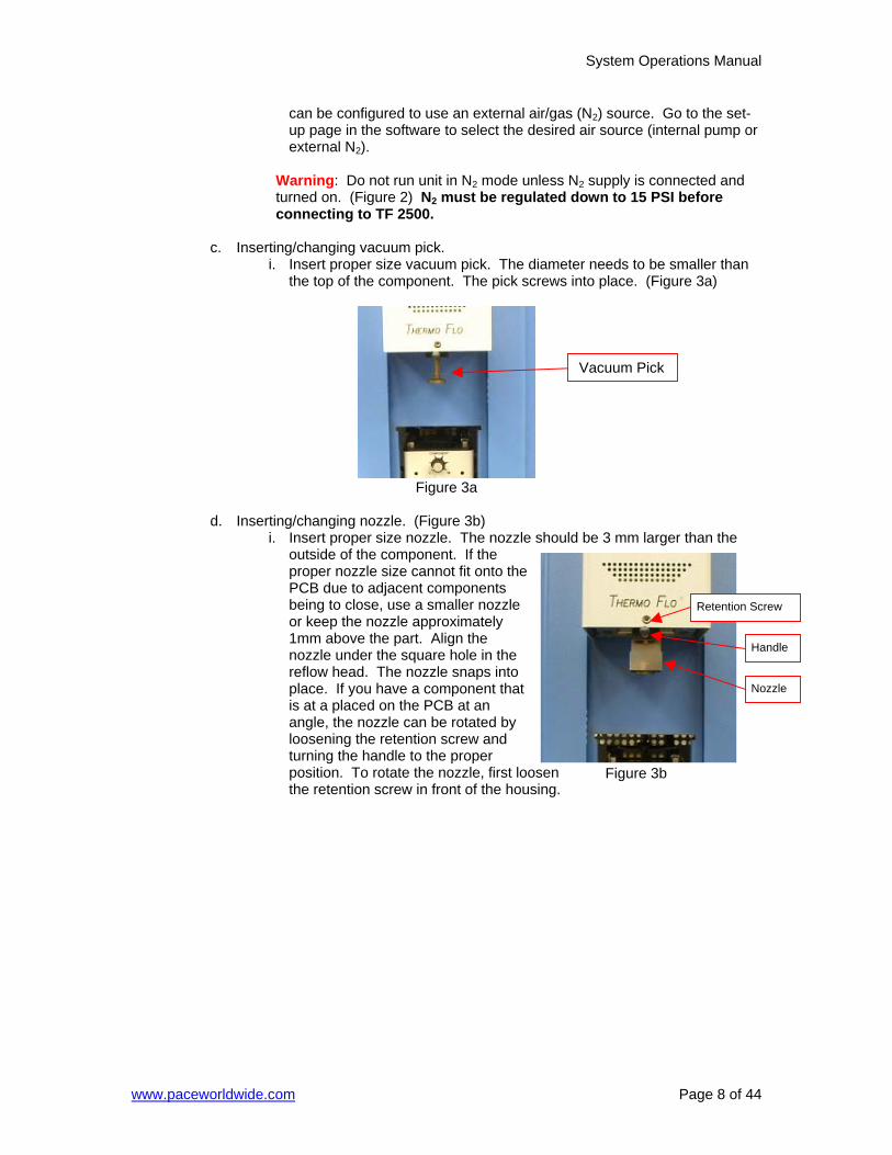
c. Inserting/changing vacuum pick.
i. Insert proper size vacuum pick. The diameter needs to be smaller than the top of the component. The pick screws into place. (Figure 3a)
Figure 3a
d. Inserting/changing nozzle. (Figure 3b)
i. Insert proper size nozzle. The nozzle should be 3 mm larger than the outside of the component. If the proper nozzle size cannot fit onto the PCB due to adjacent components being to close, use a smaller nozzle or keep the nozzle approximately 1mm above the part. Align the nozzle under the square hole in the reflow head. The nozzle snaps into place. If you have a component that is at a placed on the PCB at an angle, the nozzle can be rotated by loosening the retention screw and turning the handle to the proper position. To rotate the nozzle, first loosen the retention screw in front of the housing.
Vacuum Pick
Retention Screw
Nozzle
Handle
Figure 3b
System Operations Manual
www.paceworldwide.com Page 9 of 44
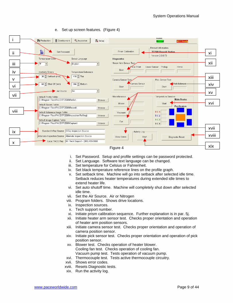
e. Set up screen features. (Figure 4)
Figure 4
i. Set Password. Setup and profile settings can be password protected. ii. Set Language. Software text language can be changed. iii. Set temperature for Celsius or Fahrenheit. iv. Set black temperature reference lines on the profile graph. v. Set setback time. Machine will go into setback after selected idle time.
Setback reduces heater temperatures during extended idle times to extend heater life.
vi. Set auto shutoff time. Machine will completely shut down after selected idle time.
vii. Set the Air Source. Air or Nitrogen viii. Program folders. Shows drive locations. ix. Inspection sources. x. Tech support number. xi. Initiate prism calibration sequence. Further explanation is in par. 5j. xii. Initiate heater arm sensor test. Checks proper orientation and operation
of heater arm position sensors. xiii. Initiate camera sensor test. Checks proper orientation and operation of
camera position sensor. xiv. Initiate pick sensor test. Checks proper orientation and operation of pick
position sensor. xv. Blower test. Checks operation of heater blower.
Cooling fan test. Checks operation of cooling fan. Vacuum pump test. Tests operation of vacuum pump.
xvi. Thermocouple test. Tests active thermocouple circuitry. xvii. Shows error codes. xviii. Resets Diagnostic tests. xix. Run the activity log.
i
ii
iii
ivvvi
vii
viii
ix
x
xi
xii
xiiixiv
xv
xvi
xviixviii
xix
System Operations Manual
www.paceworldwide.com Page 10 of 44
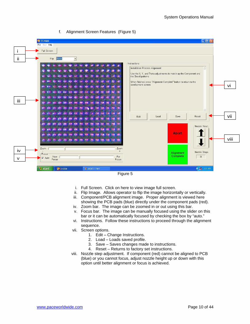
f. Alignment Screen Features (Figure 5)
Figure 5
i. Full Screen. Click on here to view image full screen. ii. Flip Image. Allows operator to flip the image horizontally or vertically. iii. Component/PCB alignment image. Proper alignment is viewed here
showing the PCB pads (blue) directly under the component pads (red). iv. Zoom bar. The image can be zoomed in or out using this bar. v. Focus bar. The image can be manually focused using the slider on this
bar or it can be automatically focused by checking the box by “auto.” vi. Instructions. Follow these instructions to proceed through the alignment
sequence. vii. Screen options.
1. Edit – Change Instructions. 2. Load – Loads saved profile. 3. Save – Saves changes made to instructions. 4. Reset – Returns to factory set instructions.
viii. Nozzle step adjustment. If component (red) cannot be aligned to PCB (blue) or you cannot focus, adjust nozzle height up or down with this option until better alignment or focus is achieved.
iii
ivv
vi
vii
viii
iii
System Operations Manual
www.paceworldwide.com Page 11 of 44
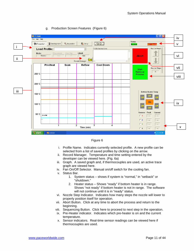
g. Production Screen Features (Figure 6)
Figure 6
i. Profile Name. Indicates currently selected profile. A new profile can be
selected from a list of saved profiles by clicking on the arrow. ii. Record Manager. Temperature and time setting entered by the
developer can be viewed here. (Fig. 6a) iii. Graph. A saved graph and, if thermocouples are used, an active trace
graph are viewed here. iv. Fan On/Off Selector. Manual on/off switch for the cooling fan. v. Status Bar.
1. System status – shows if system is “normal,” in “setback” or “shutdown.”
2. Heater status – Shows “ready” if bottom heater is in range. Shows “not ready” if bottom heater is not in range. The software will not continue until it is in “ready” status.
vi. Nozzle Step Indicator. Indicates how many steps the nozzle will lower to properly position itself for operation.
vii. Abort Button. Click at any time to abort the process and return to the beginning.
viii. Sequencing Button. Click here to proceed to next step in the operation. ix. Pre-Heater indicator. Indicates which pre-heater is on and the current
temperature. x. Sensor indicators. Real-time sensor readings can be viewed here if
thermocouples are used.
ii
iii
vi
vii
viii
ix
x
i
ivv
System Operations Manual
www.paceworldwide.com Page 12 of 44
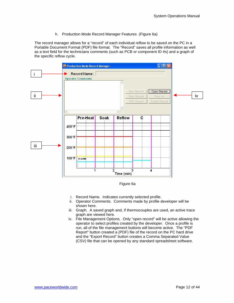
h. Production Mode Record Manager Features (Figure 6a)
The record manager allows for a “record” of each individual reflow to be saved on the PC in a Portable Document Format (PDF) file format. The “Record” saves all profile information as well as a text field for the technicians comments (such as PCB or component ID #s) and a graph of the specific reflow cycle.
Figure 6a
i. Record Name. Indicates currently selected profile. ii. Operator Comments. Comments made by profile developer will be
shown here. iii. Graph. A saved graph and, if thermocouples are used, an active trace
graph are viewed here. iv. File Management Options. Only “open record” will be active allowing the
operator to select profiles created by the developer. Once a profile is run, all of the file management buttons will become active. The “PDF Report” button created a (PDF) file of the record on the PC hard drive and the “Export Record” button creates a Comma Separated Value (CSV) file that can be opened by any standard spreadsheet software.
i
ii iv
iii
System Operations Manual
www.paceworldwide.com Page 13 of 44
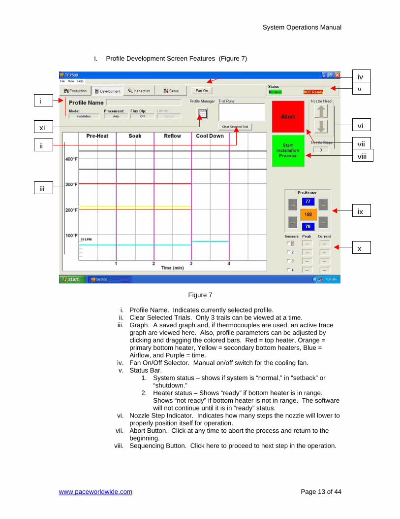
i. Profile Development Screen Features (Figure 7)
Figure 7
i. Profile Name. Indicates currently selected profile. ii. Clear Selected Trials. Only 3 trails can be viewed at a time. iii. Graph. A saved graph and, if thermocouples are used, an active trace
graph are viewed here. Also, profile parameters can be adjusted by clicking and dragging the colored bars. Red = top heater, Orange = primary bottom heater, Yellow = secondary bottom heaters, Blue = Airflow, and Purple = time.
iv. Fan On/Off Selector. Manual on/off switch for the cooling fan. v. Status Bar.
1. System status – shows if system is “normal,” in “setback” or “shutdown.”
2. Heater status – Shows “ready” if bottom heater is in range. Shows “not ready” if bottom heater is not in range. The software will not continue until it is in “ready” status.
vi. Nozzle Step Indicator. Indicates how many steps the nozzle will lower to properly position itself for operation.
vii. Abort Button. Click at any time to abort the process and return to the beginning.
viii. Sequencing Button. Click here to proceed to next step in the operation.
i
ii
iii
v
vi
viiviii
ix
x
iv
xi

System Operations Manual
www.paceworldwide.com Page 14 of 44
ix. Pre-Heater indicator. Indicates which pre-heater is on and the current temperature. To turn on or off individual secondary preheaters click on the graphic. While individual secondary preheaters can be turned on and off, they must all be set at the same temperature. They can be adjusted by dragging the yellow lines on the graph or through the profile manager.
x. Sensor indicators. Real-time sensor readings can be viewed here if thermocouples are used.
xi. Profile Manager. Temperature and time setting entered by the developer can be viewed here. (Fig. 7a)
System Operations Manual
www.paceworldwide.com Page 15 of 44
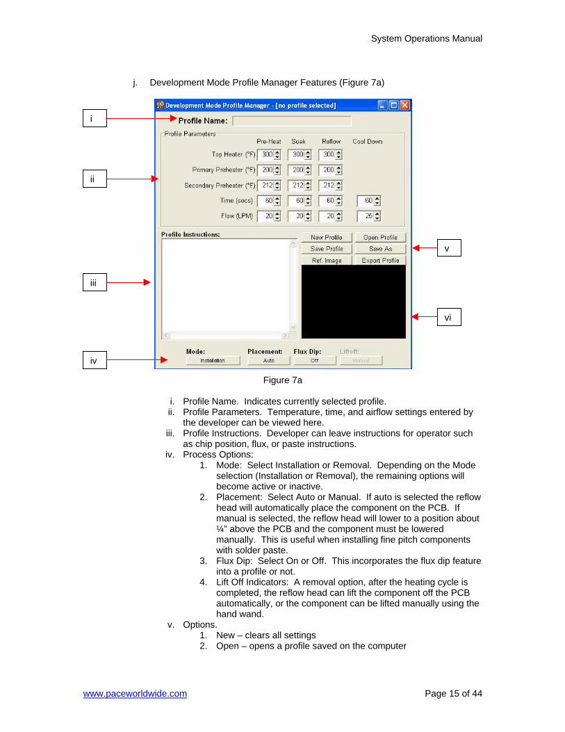
j. Development Mode Profile Manager Features (Figure 7a)
Figure 7a
i. Profile Name. Indicates currently selected profile. ii. Profile Parameters. Temperature, time, and airflow settings entered by
the developer can be viewed here. iii. Profile Instructions. Developer can leave instructions for operator such
as chip position, flux, or paste instructions. iv. Process Options:
1. Mode: Select Installation or Removal. Depending on the Mode selection (Installation or Removal), the remaining options will become active or inactive.
2. Placement: Select Auto or Manual. If auto is selected the reflow head will automatically place the component on the PCB. If manual is selected, the reflow head will lower to a position about ¼” above the PCB and the component must be lowered manually. This is useful when installing fine pitch components with solder paste.
3. Flux Dip: Select On or Off. This incorporates the flux dip feature into a profile or not.
4. Lift Off Indicators: A removal option, after the heating cycle is completed, the reflow head can lift the component off the PCB automatically, or the component can be lifted manually using the hand wand.
v. Options. 1. New – clears all settings 2. Open – opens a profile saved on the computer
v
vi
iv
iii
ii
i

System Operations Manual
www.paceworldwide.com Page 16 of 44
3. Save – saves profile to file name showing in the profile name window
4. Save as – saves profile to new file name 5. Ref. Image – associates a reference image saved on computer
with the specific profile. This can be used to identify a specific chip to be reworked to reduce operator error.
6. Export – saves profile as a CSV file that can be opened by ant spreadsheet software such as Excel.
vi. Reference Image. Image will be displayed here.
System Operations Manual
www.paceworldwide.com Page 17 of 44
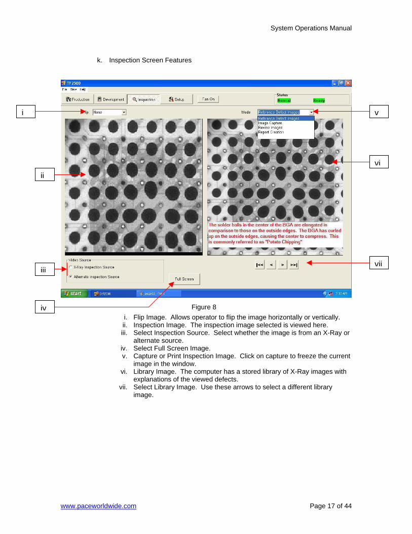
k. Inspection Screen Features
i. Flip Image. Allows operator to flip the image horizontally or vertically. ii. Inspection Image. The inspection image selected is viewed here. iii. Select Inspection Source. Select whether the image is from an X-Ray or
alternate source. iv. Select Full Screen Image. v. Capture or Print Inspection Image. Click on capture to freeze the current
image in the window. vi. Library Image. The computer has a stored library of X-Ray images with
explanations of the viewed defects. vii. Select Library Image. Use these arrows to select a different library
image.
ii
iii
iv
v
vi
vii
i
Figure 8
System Operations Manual
www.paceworldwide.com Page 18 of 44
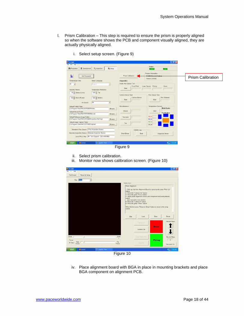
l. Prism Calibration – This step is required to ensure the prism is properly aligned
so when the software shows the PCB and component visually aligned, they are actually physically aligned.
i. Select setup screen. (Figure 9)
Figure 9
ii. Select prism calibration. iii. Monitor now shows calibration screen. (Figure 10)
Figure 10
iv. Place alignment board with BGA in place in mounting brackets and place BGA component on alignment PCB.
Prism Calibration
System Operations Manual
www.paceworldwide.com Page 19 of 44
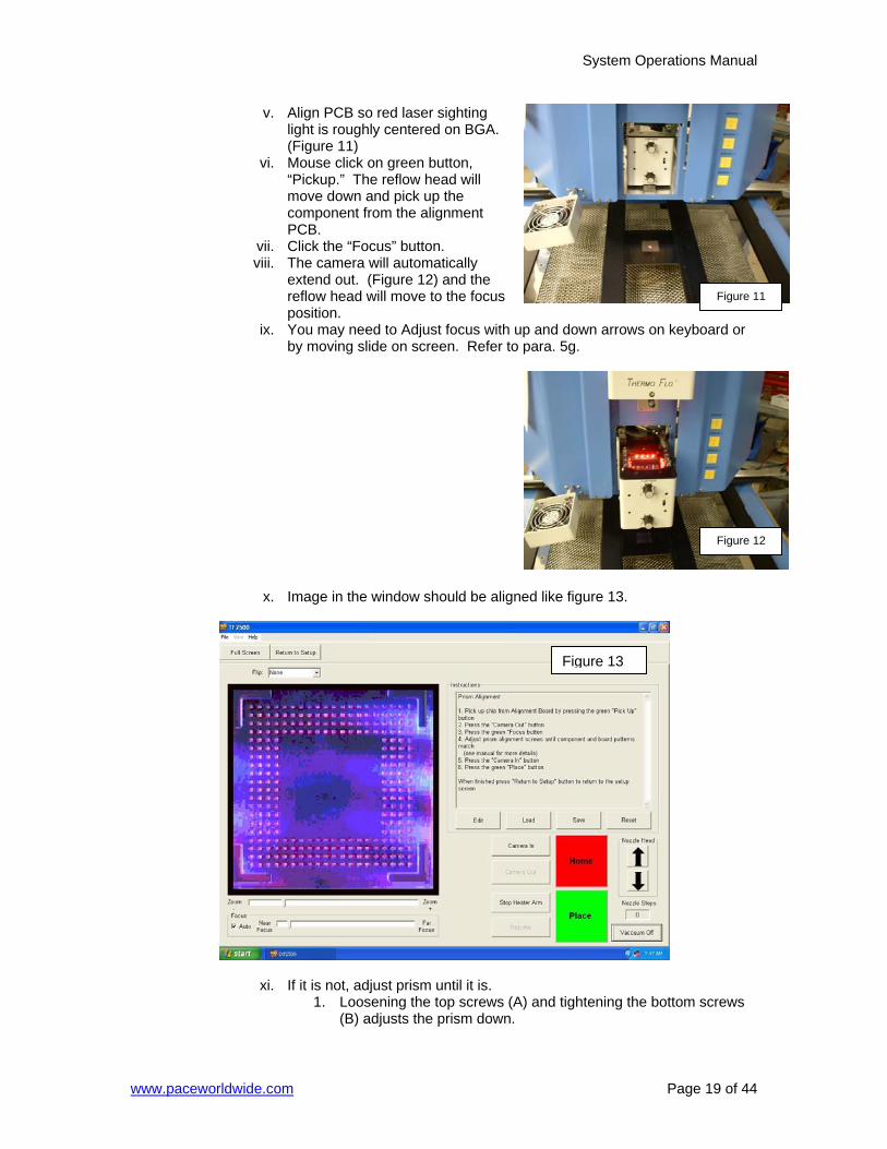
v. Align PCB so red laser sighting light is roughly centered on BGA. (Figure 11)
vi. Mouse click on green button, “Pickup.” The reflow head will move down and pick up the component from the alignment PCB.
vii. Click the “Focus” button. viii. The camera will automatically
extend out. (Figure 12) and the reflow head will move to the focus position.
ix. You may need to Adjust focus with up and down arrows on keyboard or by moving slide on screen. Refer to para. 5g.
x. Image in the window should be aligned like figure 13.
xi. If it is not, adjust prism until it is. 1. Loosening the top screws (A) and tightening the bottom screws
(B) adjusts the prism down.
Figure 11
Figure 12
Figure 13
System Operations Manual
www.paceworldwide.com Page 20 of 44
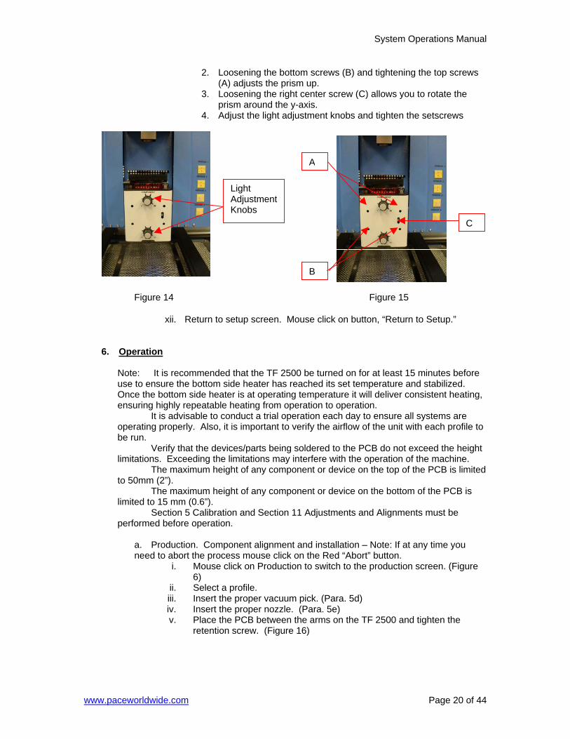
2. Loosening the bottom screws (B) and tightening the top screws (A) adjusts the prism up.
3. Loosening the right center screw (C) allows you to rotate the prism around the y-axis.
4. Adjust the light adjustment knobs and tighten the setscrews
xii. Return to setup screen. Mouse click on button, “Return to Setup.”
6. Operation
Note: It is recommended that the TF 2500 be turned on for at least 15 minutes before use to ensure the bottom side heater has reached its set temperature and stabilized. Once the bottom side heater is at operating temperature it will deliver consistent heating, ensuring highly repeatable heating from operation to operation. It is advisable to conduct a trial operation each day to ensure all systems are operating properly. Also, it is important to verify the airflow of the unit with each profile to be run. Verify that the devices/parts being soldered to the PCB do not exceed the height limitations. Exceeding the limitations may interfere with the operation of the machine. The maximum height of any component or device on the top of the PCB is limited to 50mm (2”). The maximum height of any component or device on the bottom of the PCB is limited to 15 mm (0.6”). Section 5 Calibration and Section 11 Adjustments and Alignments must be performed before operation.
a. Production. Component alignment and installation – Note: If at any time you need to abort the process mouse click on the Red “Abort” button.
i. Mouse click on Production to switch to the production screen. (Figure 6)
ii. Select a profile. iii. Insert the proper vacuum pick. (Para. 5d) iv. Insert the proper nozzle. (Para. 5e) v. Place the PCB between the arms on the TF 2500 and tighten the
retention screw. (Figure 16)
Light Adjustment Knobs
C
B
Figure 14 Figure 15
A
System Operations Manual
www.paceworldwide.com Page 21 of 44
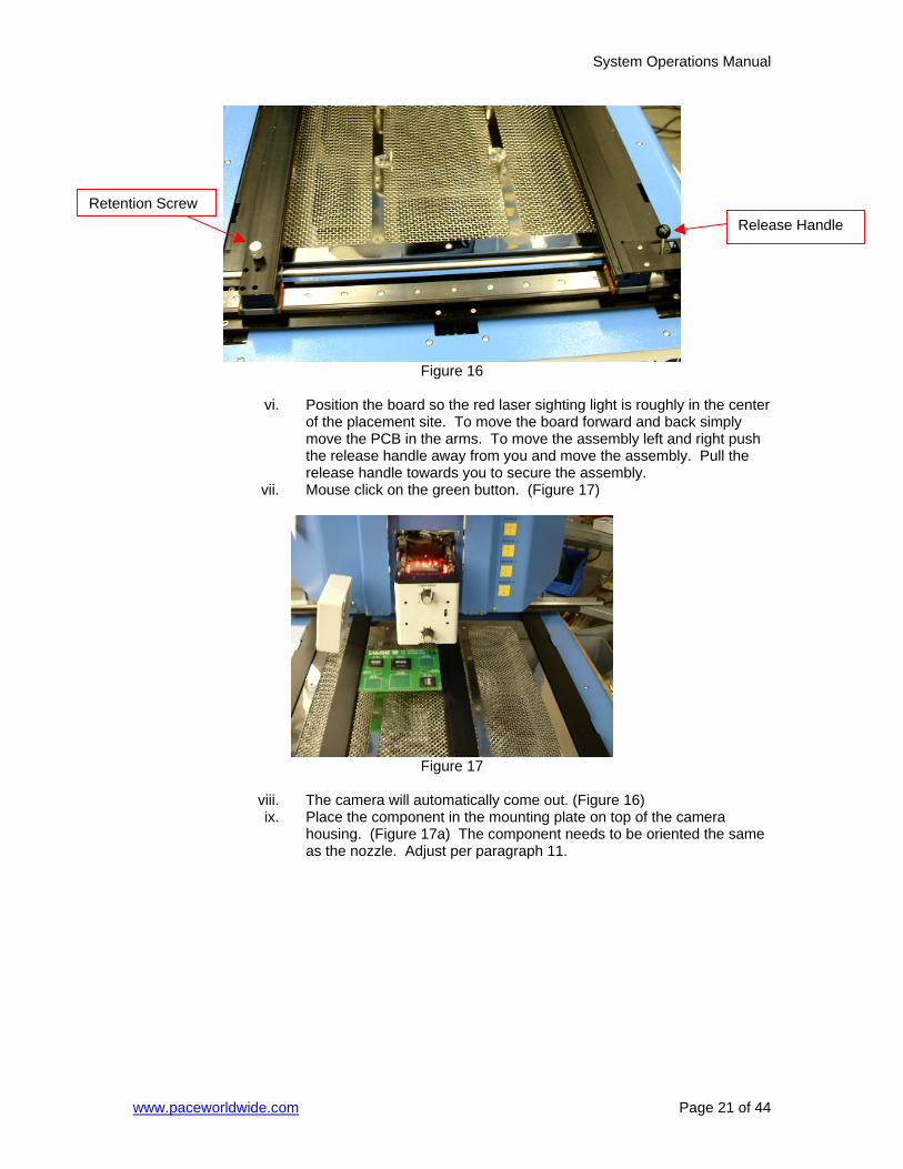
Figure 16
vi. Position the board so the red laser sighting light is roughly in the center
of the placement site. To move the board forward and back simply move the PCB in the arms. To move the assembly left and right push the release handle away from you and move the assembly. Pull the release handle towards you to secure the assembly.
vii. Mouse click on the green button. (Figure 17)
Figure 17
viii. The camera will automatically come out. (Figure 16) ix. Place the component in the mounting plate on top of the camera
housing. (Figure 17a) The component needs to be oriented the same as the nozzle. Adjust per paragraph 11.
Retention Screw Release Handle
System Operations Manual
www.paceworldwide.com Page 22 of 44
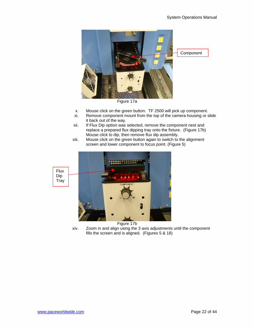
Figure 17a
x. Mouse click on the green button. TF 2500 will pick up component. xi. Remove component mount from the top of the camera housing or slide
it back out of the way. xii. If Flux Dip option was selected, remove the component nest and
replace a prepared flux dipping tray onto the fixture. (Figure 17b) Mouse click to dip, then remove flux dip assembly.
xiii. Mouse click on the green button again to switch to the alignment screen and lower component to focus point. (Figure 5)
Figure 17b
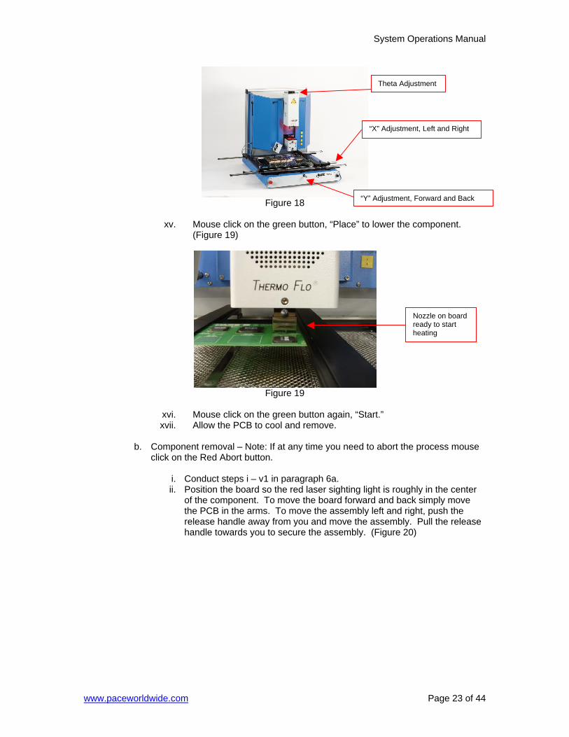
xiv. Zoom in and align using the 3 axis adjustments until the component fills the screen and is aligned. (Figures 5 & 18)
Component
Flux Dip Tray
System Operations Manual
www.paceworldwide.com Page 23 of 44
Figure 18
xv. Mouse click on the green button, “Place” to lower the component.
(Figure 19)
Figure 19
xvi. Mouse click on the green button again, “Start.” xvii. Allow the PCB to cool and remove.
b. Component removal – Note: If at any time you need to abort the process mouse
click on the Red Abort button.
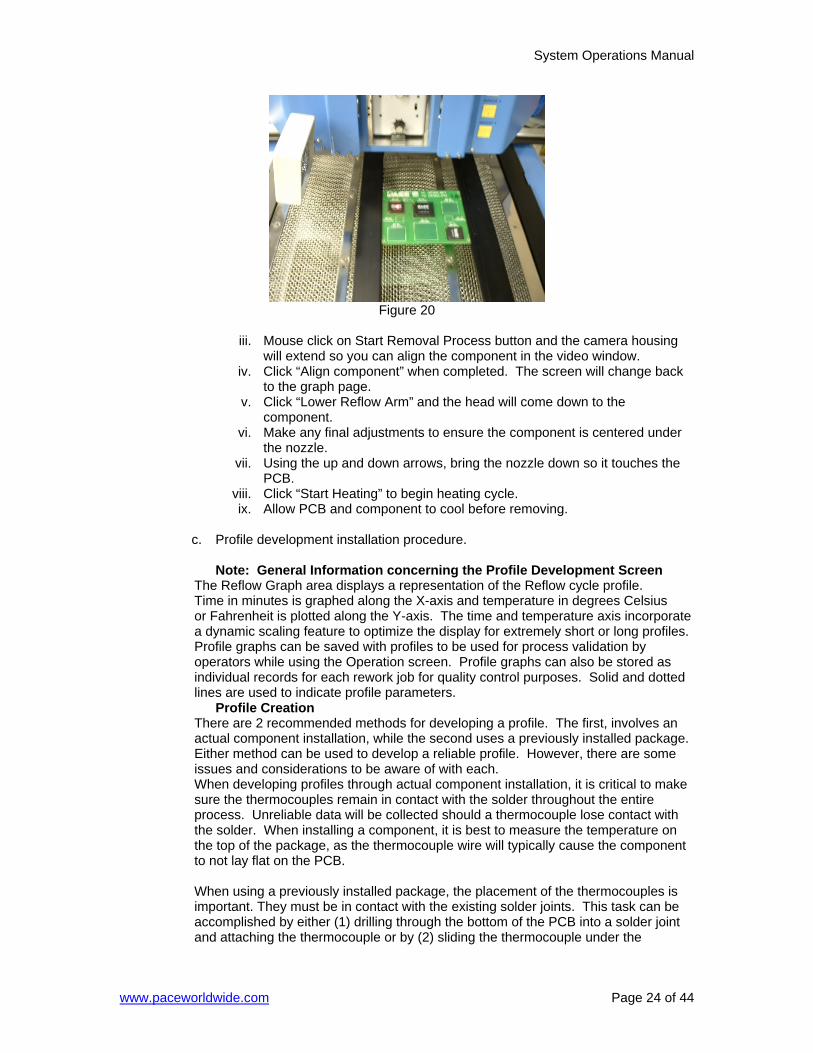
i. Conduct steps i – v1 in paragraph 6a. ii. Position the board so the red laser sighting light is roughly in the center
of the component. To move the board forward and back simply move the PCB in the arms. To move the assembly left and right, push the release handle away from you and move the assembly. Pull the release handle towards you to secure the assembly. (Figure 20)
Nozzle on board ready to start heating
Theta Adjustment
“X” Adjustment, Left and Right
“Y” Adjustment, Forward and Back
System Operations Manual
www.paceworldwide.com Page 24 of 44
Figure 20
iii. Mouse click on Start Removal Process button and the camera housing
will extend so you can align the component in the video window. iv. Click “Align component” when completed. The screen will change back
to the graph page. v. Click “Lower Reflow Arm” and the head will come down to the
component. vi. Make any final adjustments to ensure the component is centered under
the nozzle. vii. Using the up and down arrows, bring the nozzle down so it touches the
PCB. viii. Click “Start Heating” to begin heating cycle. ix. Allow PCB and component to cool before removing.
c. Profile development installation procedure.
Note: General Information concerning the Profile Development Screen
The Reflow Graph area displays a representation of the Reflow cycle profile. Time in minutes is graphed along the X-axis and temperature in degrees Celsius or Fahrenheit is plotted along the Y-axis. The time and temperature axis incorporate a dynamic scaling feature to optimize the display for extremely short or long profiles. Profile graphs can be saved with profiles to be used for process validation by operators while using the Operation screen. Profile graphs can also be stored as individual records for each rework job for quality control purposes. Solid and dotted lines are used to indicate profile parameters.
Profile Creation There are 2 recommended methods for developing a profile. The first, involves an actual component installation, while the second uses a previously installed package. Either method can be used to develop a reliable profile. However, there are some issues and considerations to be aware of with each. When developing profiles through actual component installation, it is critical to make sure the thermocouples remain in contact with the solder throughout the entire process. Unreliable data will be collected should a thermocouple lose contact with the solder. When installing a component, it is best to measure the temperature on the top of the package, as the thermocouple wire will typically cause the component to not lay flat on the PCB. When using a previously installed package, the placement of the thermocouples is important. They must be in contact with the existing solder joints. This task can be accomplished by either (1) drilling through the bottom of the PCB into a solder joint and attaching the thermocouple or by (2) sliding the thermocouple under the

System Operations Manual
www.paceworldwide.com Page 25 of 44
package in the case of a BGA or along side in the case of other SMD’s. When sliding a thermo couple under a component, it is critical that the thermocouple be in contact with the solder. Method 2 is the most commonly used. Information from the thermocouples will assist in determining the proper time and temperature parameters. In general, the following guidelines should be adhered to when developing profiles.
Ramp and Maximum Temperatures Acceptable ramp rates and maximum temperatures should be obtained from the component manufacturer. Typical ramp rates are 2-5 ºC/s (4-9 ºF/s) for plastic parts and 1 ºC/s (2 ºF/s) for ceramic parts. It is recommended to select a maximum temperature below the manufacturer’s specification to provide for a margin of safety. Typically, 20 ºC below maximum specified temperature is selected.
Pre-Heat Phase 1. In a “step profile,” the top of the PCB and package should reach a stable temperature of 95-105 ºC. If plotting the temperature curve, the trace will usually level off within this temperature range. 2. If a “linear slope” is desired, pre-heat and soak phases are combined. Both the package and the PCB are warmed at a constant ramp rate (usually 2-4 ºC/second) until the desired soak temperature is reached.
Soak Phase The soak phase is a crucial part of the reflow process. During this period, the flux activates and drives off volatiles and excess flux. A temperature of 145-165 ºC (determined by the activation temperature of the flux used) should be maintained for approximately 20-40 seconds. This allows for uniform ramping across the entire package and PCB during reflow.
Reflow Phase During this phase, the solder reaches solder melt and forms joints between the package and the lands. It is critical for all areas of the component to reach solder melt together and all solder joints remain in a liquid state for at least 10-20 seconds. Generally, plastic packages should not be exposed to temperatures higher than 220 ºC. Always consult the device specifications for maximum temperature recommendations. As a rule of thumb, a safe “maximum temperature” is the maximum temp specified by the manufacturer minus 20ºC. Lower temperatures and shorter times are common in CSPs and FCs. The lowest temperatures possible should always be used to ensure safety of the device and PCB.
Cool Down Phase The cool down phase is necessary to bring the temperature of the package, solder joints and PCB under the package below solder melt temperatures. Cooling should be controlled. A good reference is to use the same cool down rate as for ramp up. The cooling fan on the TF 2500 will remain on for a minimum of 30 seconds from the start of the cool down cycle. Some types of components (like CBGAs) should be allowed to cool without external assistance from the cooling fan. When installing these packages, turn the fan away from the PCB so the air doesn’t blow on it.
General Using one of the two baseline (default) profiles will provide a good starting point for profile development. The reflow graph provides an excellent tool for monitoring profile parameters and fine tuning or perfecting the profile development process. When adjusting profile parameters “on-the-fly,” all changes are reflected immediately on the profile development screen and graph. Procedure
i. If the component needs to be placed first, conduct steps in paragraph 6a to step xv then do sections ii, vii through x below.
ii. Mouse click on Profile for the Profile Development Screen. (Figure 7) iii. Conduct steps ii through v in paragraph 6a. iv. Position the board so the red laser sighting light is roughly in the center
of the component. To move the board forward and back simply move
System Operations Manual
www.paceworldwide.com Page 26 of 44
the PCB in the arms. To move the assembly left and right, push the release handle away from you, and move the assembly or use the micrometers. Pull the release handle towards you to secure the assembly, or use the micrometers.
v. Mouse click the cycle start button. Make adjustments in accordance with paragraph 5i.
vi. To return to the beginning of the development stage mouse click on the cycle start button.
vii. If you’re finished, allow the PCB to cool and remove.
7. Temperature, Time, and Airflow Control
a. Heater temperatures are adjusted by changing the numbers on the profile screen by clicking on the arrows, selecting and over-typing, or by moving the temperature bars on the graph. Red = top heater, Orange = primary bottom heater, Yellow = secondary bottom heaters, Blue = Airflow, and Purple = time. (See paragraph 6.c.ii.)
8. Available Nozzles, Accessories, and Optional Items
a. A complete list of nozzles and accessories is on our Web site,
www.paceworldwide.com
9. Maintenance
Caution: Disconnect the main power supply and computer cables before opening the TF 2500 door, replacing any component or before performing any routine maintenance.
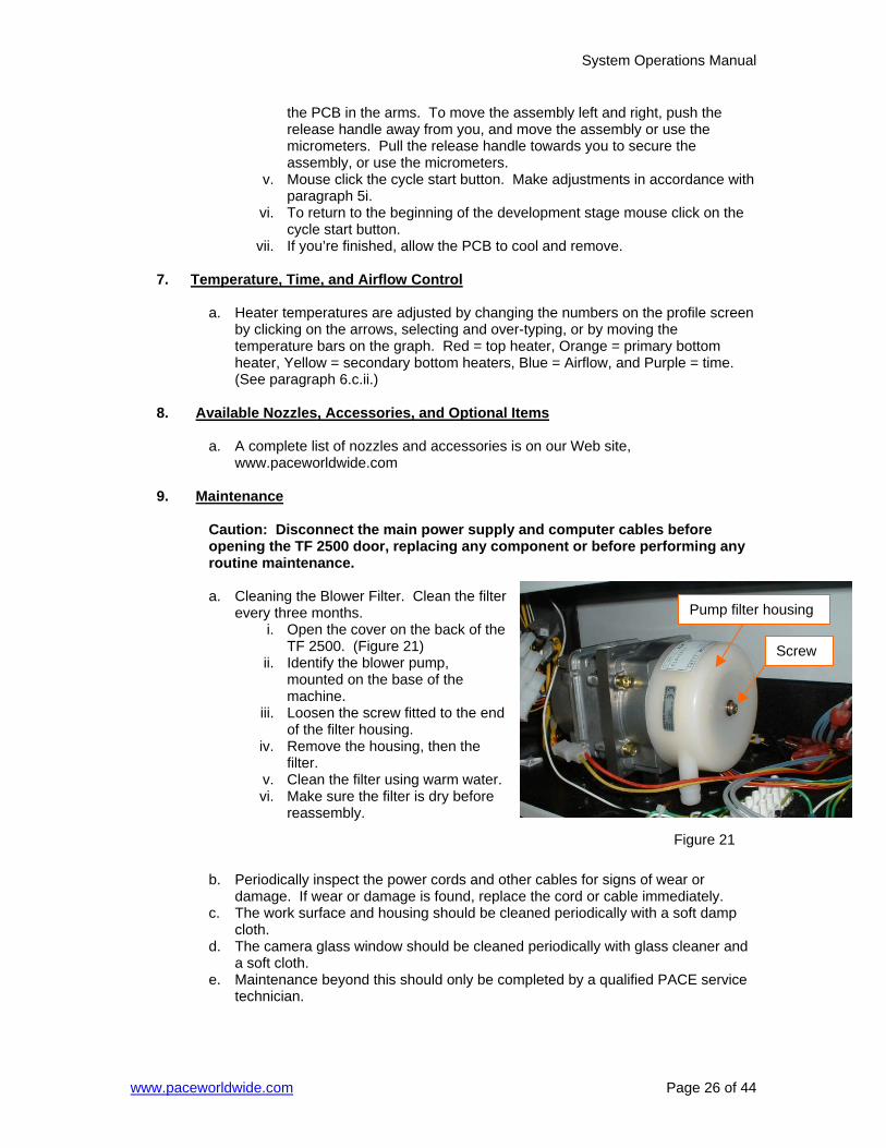
a. Cleaning the Blower Filter. Clean the filter
every three months. i. Open the cover on the back of the
TF 2500. (Figure 21) ii. Identify the blower pump,
mounted on the base of the machine.
iii. Loosen the screw fitted to the end of the filter housing.
iv. Remove the housing, then the filter.
v. Clean the filter using warm water. vi. Make sure the filter is dry before
reassembly.
b. Periodically inspect the power cords and other cables for signs of wear or damage. If wear or damage is found, replace the cord or cable immediately.
c. The work surface and housing should be cleaned periodically with a soft damp cloth.
d. The camera glass window should be cleaned periodically with glass cleaner and a soft cloth.
e. Maintenance beyond this should only be completed by a qualified PACE service technician.
Pump filter housing
Screw
Figure 21
System Operations Manual
www.paceworldwide.com Page 27 of 44
10. Heater Replacement
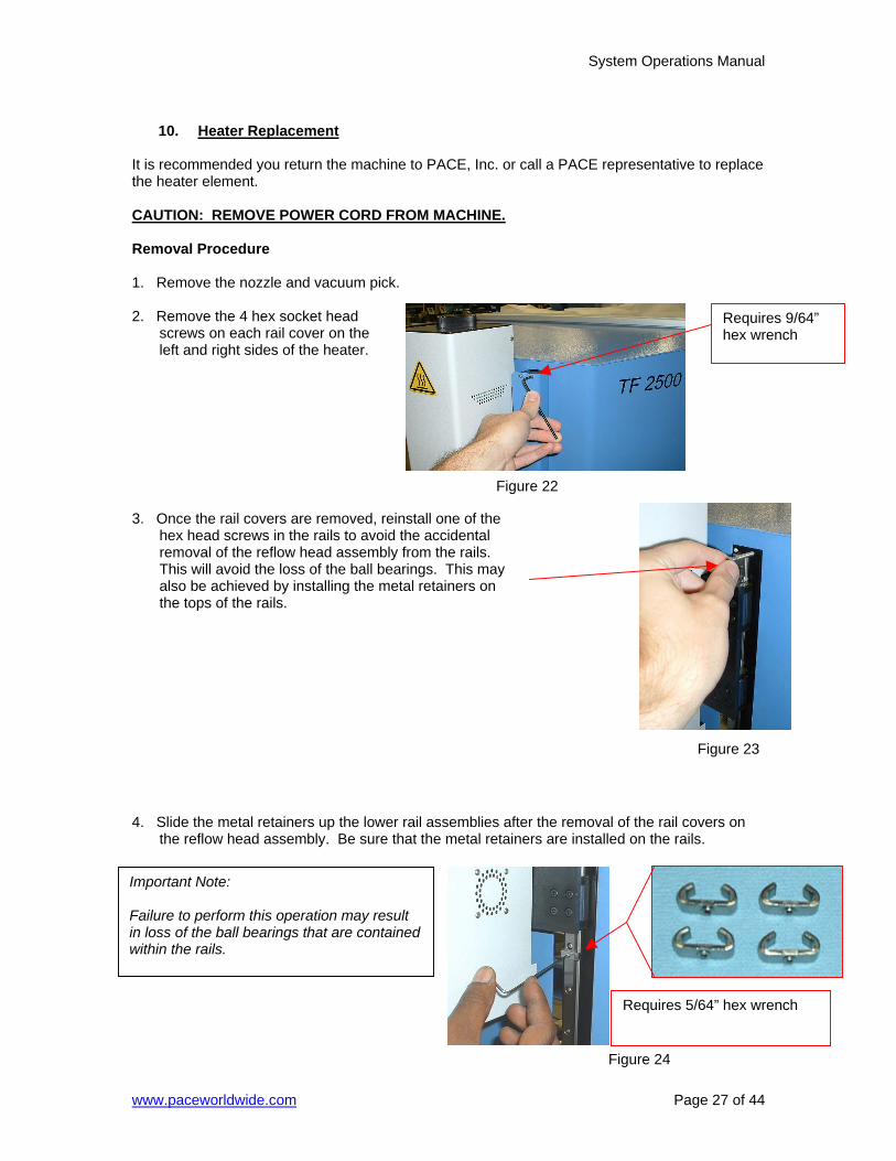
It is recommended you return the machine to PACE, Inc. or call a PACE representative to replace the heater element. CAUTION: REMOVE POWER CORD FROM MACHINE. Removal Procedure 1. Remove the nozzle and vacuum pick. 2. Remove the 4 hex socket head
screws on each rail cover on the left and right sides of the heater.
3. Once the rail covers are removed, reinstall one of the
hex head screws in the rails to avoid the accidental removal of the reflow head assembly from the rails. This will avoid the loss of the ball bearings. This may also be achieved by installing the metal retainers on the tops of the rails.
4. Slide the metal retainers up the lower rail assemblies after the removal of the rail covers on
the reflow head assembly. Be sure that the metal retainers are installed on the rails.
Important Note: Failure to perform this operation may result in loss of the ball bearings that are contained within the rails.
Requires 9/64” hex wrench
Figure 22
Figure 23
Figure 24
Requires 5/64” hex wrench
System Operations Manual
www.paceworldwide.com Page 28 of 44
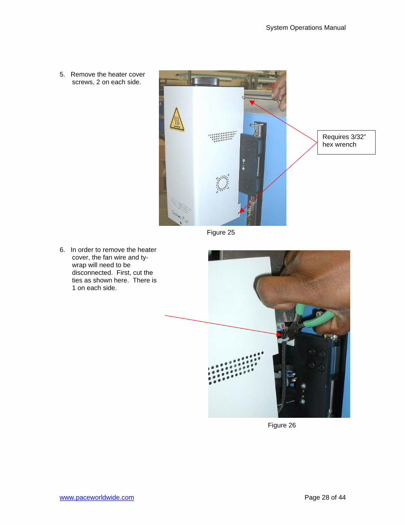
5. Remove the heater cover
screws, 2 on each side. 6. In order to remove the heater
cover, the fan wire and ty-wrap will need to be disconnected. First, cut the ties as shown here. There is 1 on each side.
Requires 3/32” hex wrench
Figure 25
Figure 26
System Operations Manual
www.paceworldwide.com Page 29 of 44
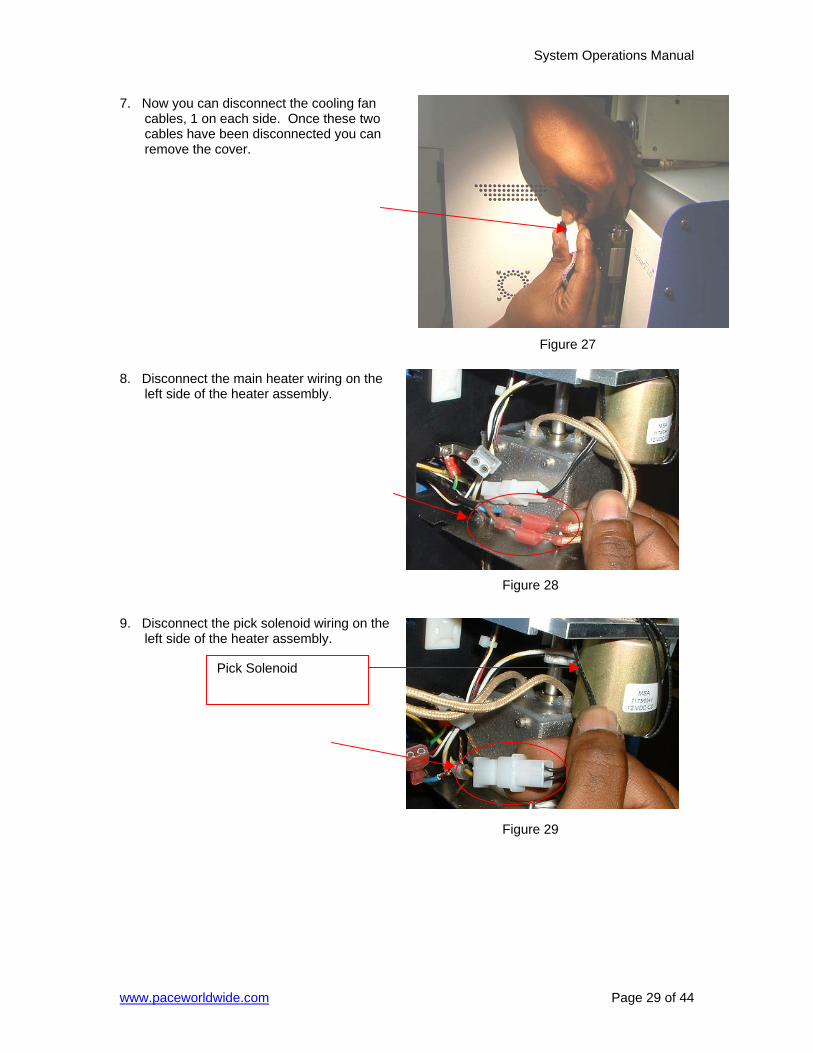
7. Now you can disconnect the cooling fan cables, 1 on each side. Once these two cables have been disconnected you can remove the cover.
8. Disconnect the main heater wiring on the
left side of the heater assembly. 9. Disconnect the pick solenoid wiring on the
left side of the heater assembly.
Pick Solenoid
Figure 27
Figure 28
Figure 29
System Operations Manual
www.paceworldwide.com Page 30 of 44
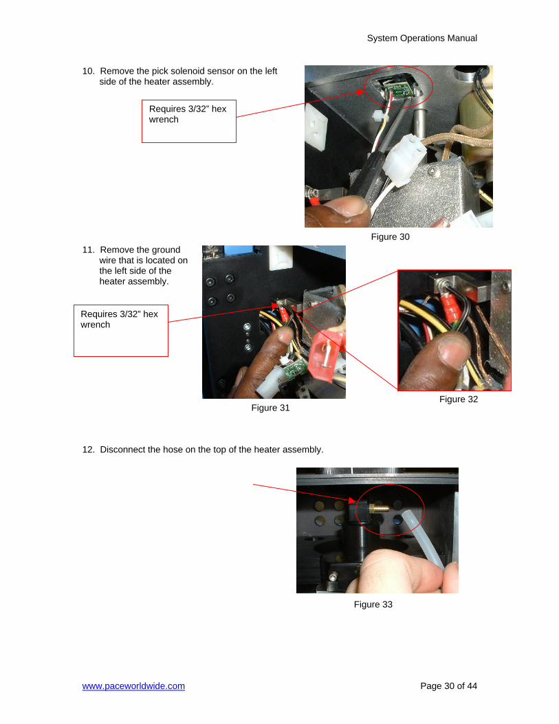
10. Remove the pick solenoid sensor on the left side of the heater assembly.
11. Remove the ground
wire that is located on the left side of the heater assembly.
12. Disconnect the hose on the top of the heater assembly.
Requires 3/32” hex wrench
Figure 30
Figure 31Figure 32
Figure 33
Requires 3/32” hex wrench
System Operations Manual
www.paceworldwide.com Page 31 of 44
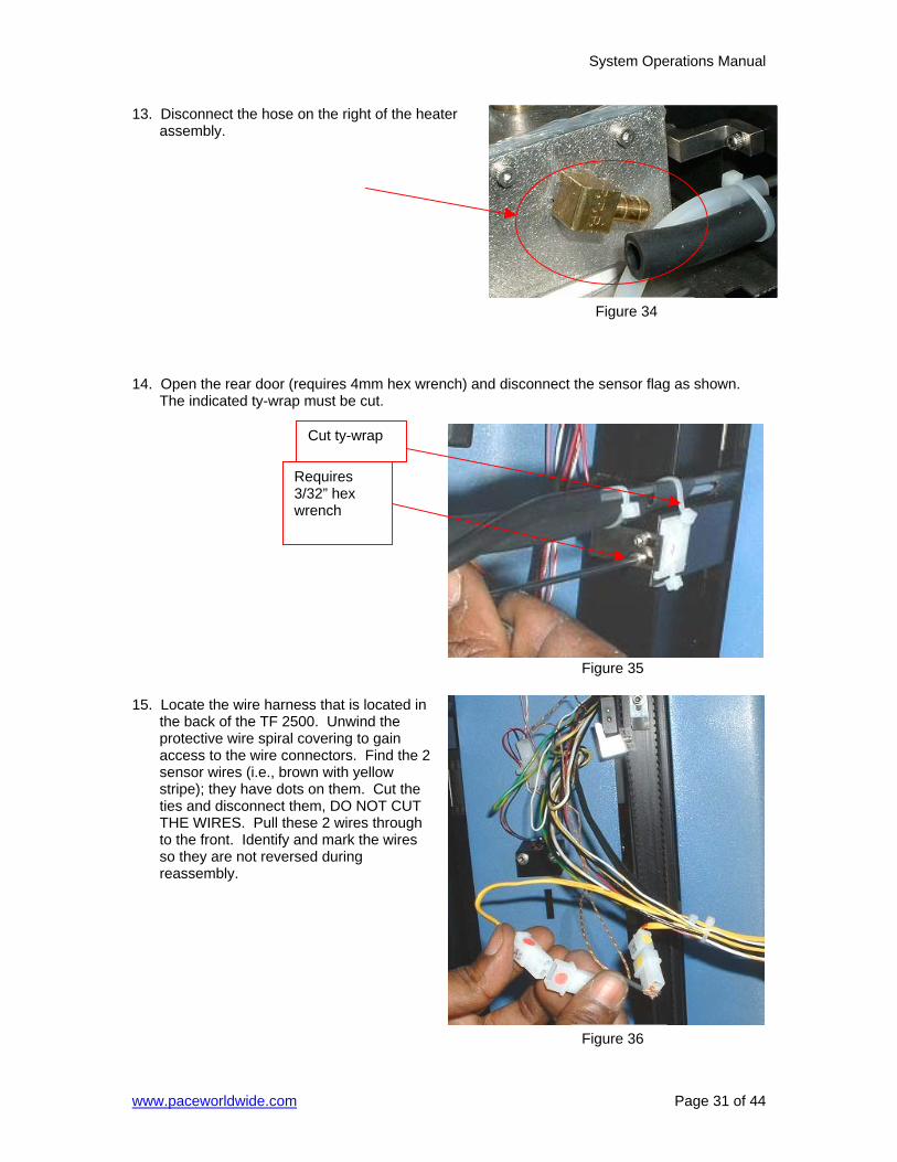
13. Disconnect the hose on the right of the heater assembly.
14. Open the rear door (requires 4mm hex wrench) and disconnect the sensor flag as shown.
The indicated ty-wrap must be cut. 15. Locate the wire harness that is located in
the back of the TF 2500. Unwind the protective wire spiral covering to gain access to the wire connectors. Find the 2 sensor wires (i.e., brown with yellow stripe); they have dots on them. Cut the ties and disconnect them, DO NOT CUT THE WIRES. Pull these 2 wires through to the front. Identify and mark the wires so they are not reversed during reassembly.
Requires 3/32” hex wrench
Cut ty-wrap
Figure 34
Figure 35
Figure 36
System Operations Manual
www.paceworldwide.com Page 32 of 44
Requires 3mm hex wrench
Figure 38
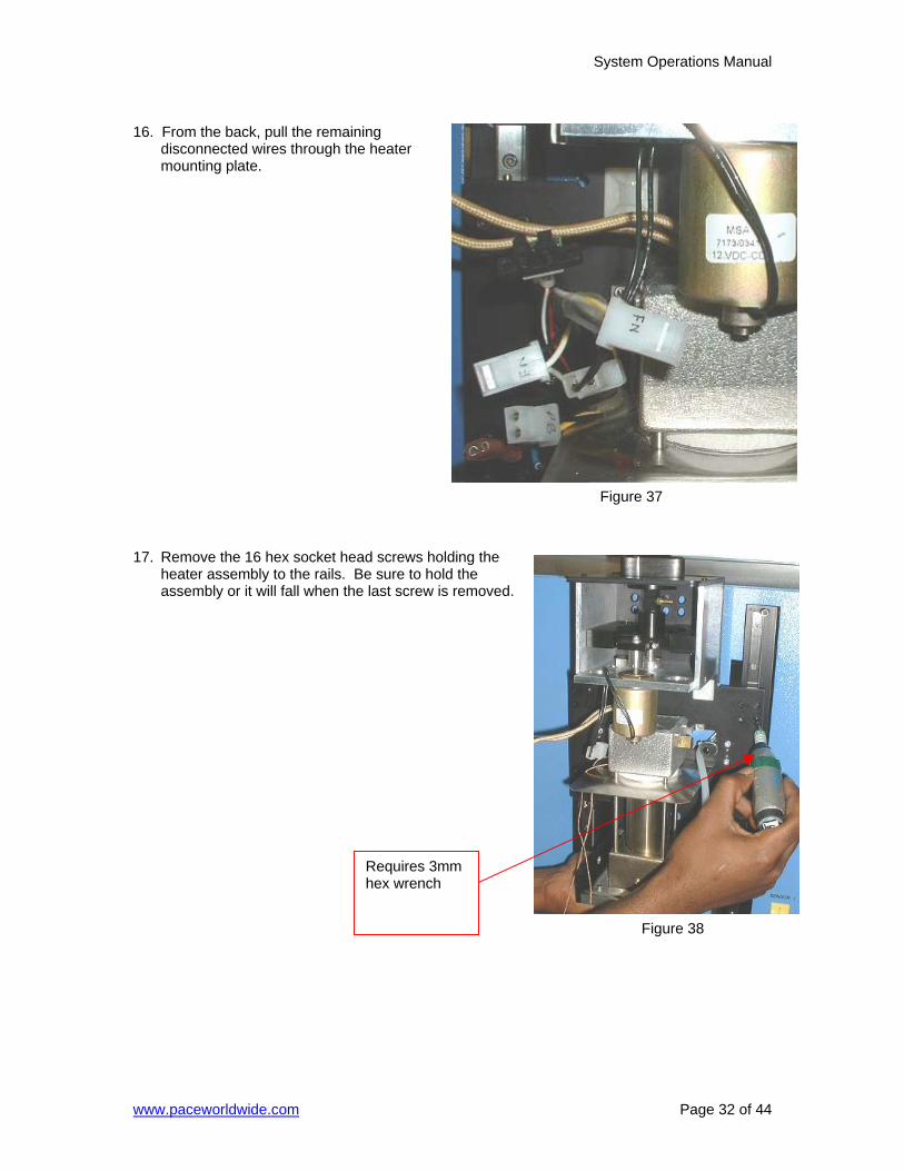
16. From the back, pull the remaining
disconnected wires through the heater mounting plate.
17. Remove the 16 hex socket head screws holding the
heater assembly to the rails. Be sure to hold the assembly or it will fall when the last screw is removed.
Figure 37
System Operations Manual
www.paceworldwide.com Page 33 of 44
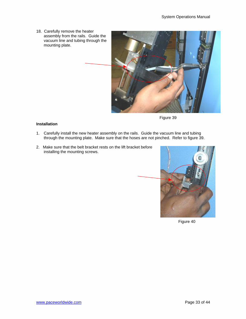
18. Carefully remove the heater assembly from the rails. Guide the vacuum line and tubing through the mounting plate.
Installation 1. Carefully install the new heater assembly on the rails. Guide the vacuum line and tubing
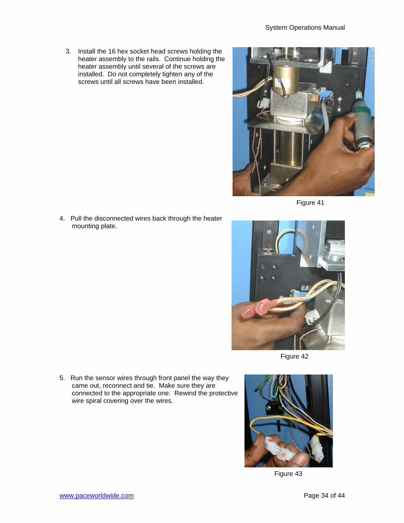
through the mounting plate. Make sure that the hoses are not pinched. Refer to figure 39. 2. Make sure that the belt bracket rests on the lift bracket before
installing the mounting screws.
Figure 39
Figure 40
System Operations Manual
www.paceworldwide.com Page 34 of 44
Figure 41
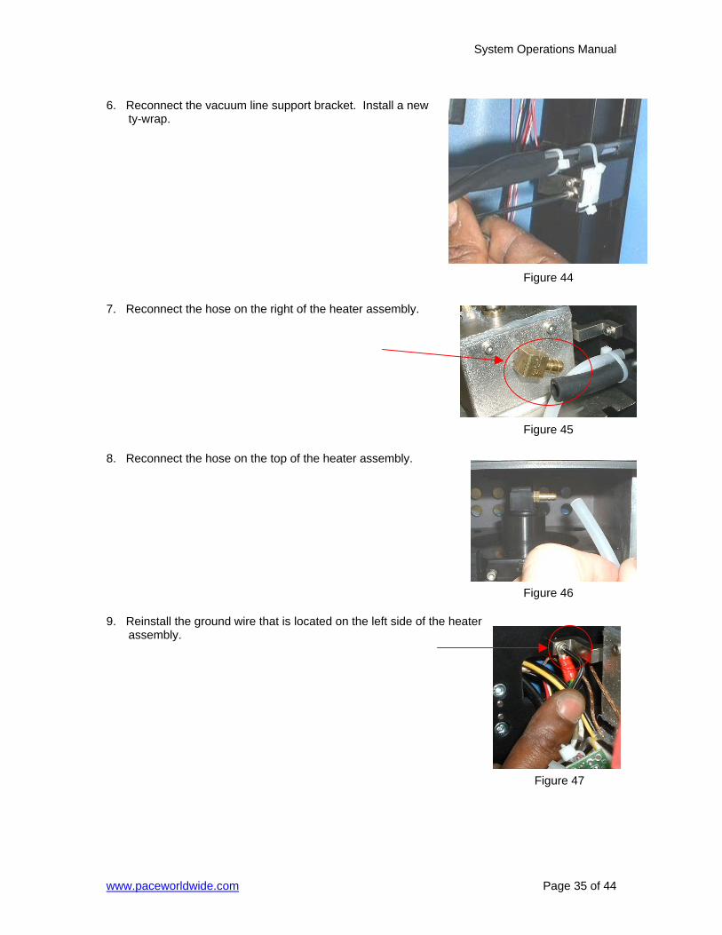
3. Install the 16 hex socket head screws holding the heater assembly to the rails. Continue holding the heater assembly until several of the screws are installed. Do not completely tighten any of the screws until all screws have been installed.
4. Pull the disconnected wires back through the heater
mounting plate. 5. Run the sensor wires through front panel the way they
came out, reconnect and tie. Make sure they are connected to the appropriate one. Rewind the protective wire spiral covering over the wires.
Figure 42
Figure 43
System Operations Manual
www.paceworldwide.com Page 35 of 44
6. Reconnect the vacuum line support bracket. Install a new
ty-wrap. 7. Reconnect the hose on the right of the heater assembly. 8. Reconnect the hose on the top of the heater assembly. 9. Reinstall the ground wire that is located on the left side of the heater
assembly.
Figure 44
Figure 45
Figure 46
Figure 47
System Operations Manual
www.paceworldwide.com Page 36 of 44
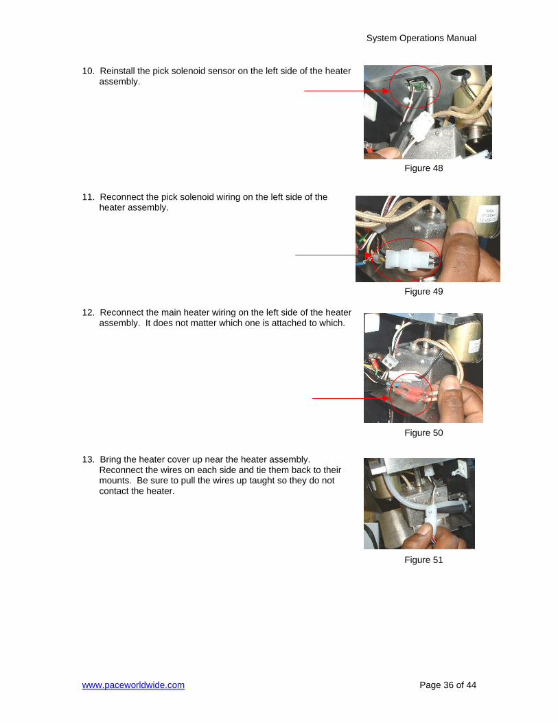
10. Reinstall the pick solenoid sensor on the left side of the heater assembly.
11. Reconnect the pick solenoid wiring on the left side of the
heater assembly. 12. Reconnect the main heater wiring on the left side of the heater
assembly. It does not matter which one is attached to which. 13. Bring the heater cover up near the heater assembly.
Reconnect the wires on each side and tie them back to their mounts. Be sure to pull the wires up taught so they do not contact the heater.
Figure 48
Figure 49
Figure 50
Figure 51
System Operations Manual
www.paceworldwide.com Page 37 of 44
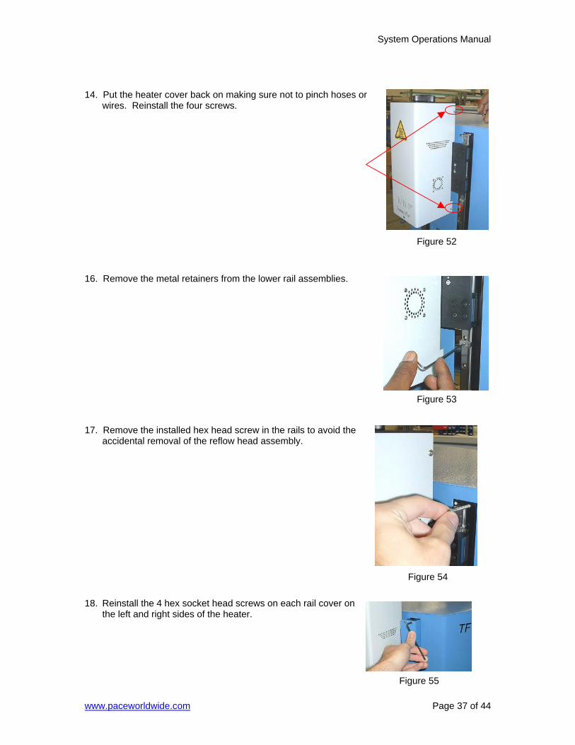
14. Put the heater cover back on making sure not to pinch hoses or
wires. Reinstall the four screws. 16. Remove the metal retainers from the lower rail assemblies. 17. Remove the installed hex head screw in the rails to avoid the
accidental removal of the reflow head assembly. 18. Reinstall the 4 hex socket head screws on each rail cover on
the left and right sides of the heater.
Figure 52
Figure 53
Figure 54
Figure 55
System Operations Manual
www.paceworldwide.com Page 38 of 44
19. Reinstall the nozzle and vacuum pick. 20. Test the heater.
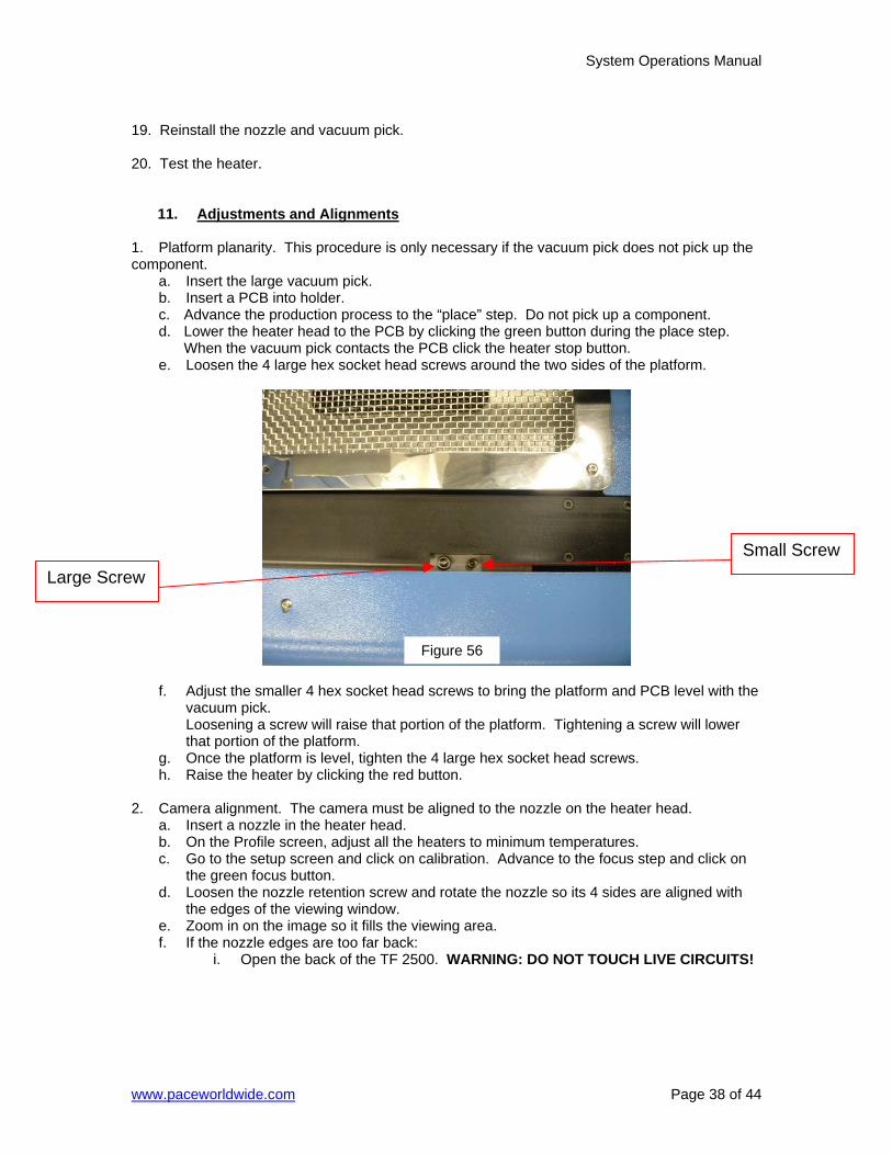
11. Adjustments and Alignments 1. Platform planarity. This procedure is only necessary if the vacuum pick does not pick up the component. a. Insert the large vacuum pick. b. Insert a PCB into holder. c. Advance the production process to the “place” step. Do not pick up a component. d. Lower the heater head to the PCB by clicking the green button during the place step.
When the vacuum pick contacts the PCB click the heater stop button. e. Loosen the 4 large hex socket head screws around the two sides of the platform.
f. Adjust the smaller 4 hex socket head screws to bring the platform and PCB level with the
vacuum pick. Loosening a screw will raise that portion of the platform. Tightening a screw will lower that portion of the platform. g. Once the platform is level, tighten the 4 large hex socket head screws. h. Raise the heater by clicking the red button. 2. Camera alignment. The camera must be aligned to the nozzle on the heater head. a. Insert a nozzle in the heater head. b. On the Profile screen, adjust all the heaters to minimum temperatures. c. Go to the setup screen and click on calibration. Advance to the focus step and click on the green focus button. d. Loosen the nozzle retention screw and rotate the nozzle so its 4 sides are aligned with
the edges of the viewing window. e. Zoom in on the image so it fills the viewing area. f. If the nozzle edges are too far back: i. Open the back of the TF 2500. WARNING: DO NOT TOUCH LIVE CIRCUITS!
Large Screw Small Screw
Figure 56
System Operations Manual
www.paceworldwide.com Page 39 of 44
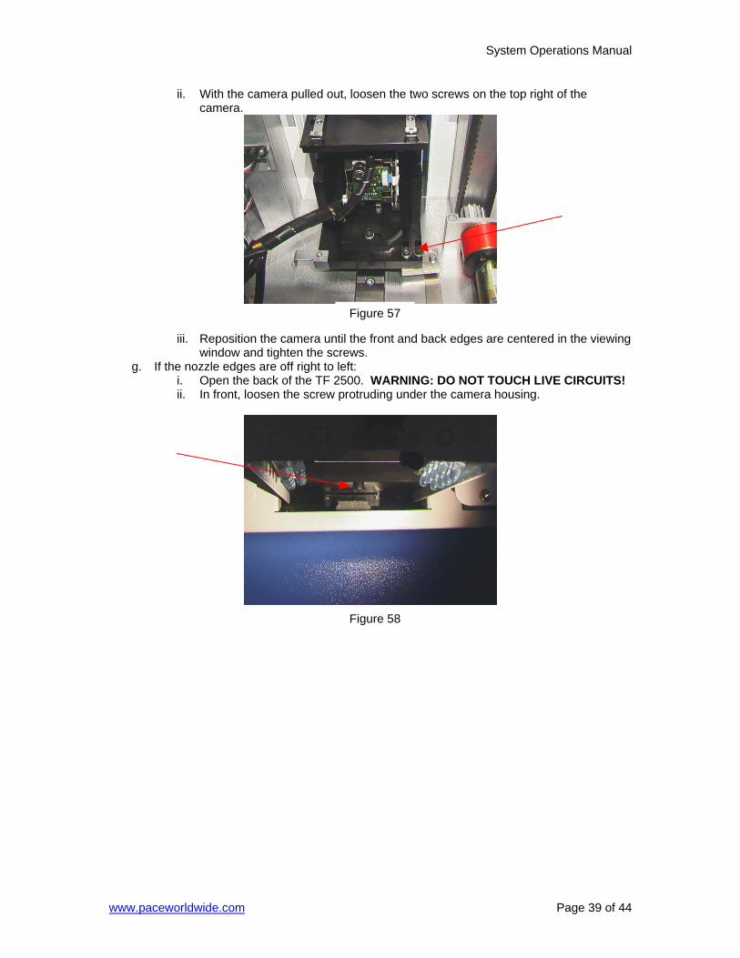
ii. With the camera pulled out, loosen the two screws on the top right of the camera.
iii. Reposition the camera until the front and back edges are centered in the viewing window and tighten the screws. g. If the nozzle edges are off right to left: i. Open the back of the TF 2500. WARNING: DO NOT TOUCH LIVE CIRCUITS! ii. In front, loosen the screw protruding under the camera housing.
Figure 57
Figure 58
System Operations Manual
www.paceworldwide.com Page 40 of 44
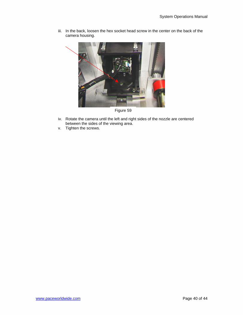
iii. In the back, loosen the hex socket head screw in the center on the back of the camera housing.
iv. Rotate the camera until the left and right sides of the nozzle are centered between the sides of the viewing area. v. Tighten the screws.
Figure 59
System Operations Manual
www.paceworldwide.com Page 41 of 44
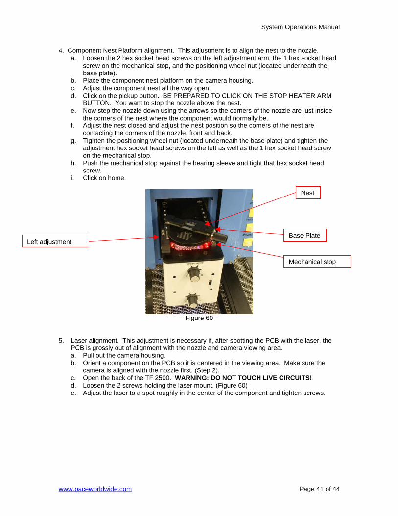
4. Component Nest Platform alignment. This adjustment is to align the nest to the nozzle. a. Loosen the 2 hex socket head screws on the left adjustment arm, the 1 hex socket head
screw on the mechanical stop, and the positioning wheel nut (located underneath the base plate).
b. Place the component nest platform on the camera housing. c. Adjust the component nest all the way open. d. Click on the pickup button. BE PREPARED TO CLICK ON THE STOP HEATER ARM BUTTON. You want to stop the nozzle above the nest. e. Now step the nozzle down using the arrows so the corners of the nozzle are just inside the corners of the nest where the component would normally be. f. Adjust the nest closed and adjust the nest position so the corners of the nest are contacting the corners of the nozzle, front and back. g. Tighten the positioning wheel nut (located underneath the base plate) and tighten the
adjustment hex socket head screws on the left as well as the 1 hex socket head screw on the mechanical stop.
h. Push the mechanical stop against the bearing sleeve and tight that hex socket head screw.
i. Click on home.
Figure 60
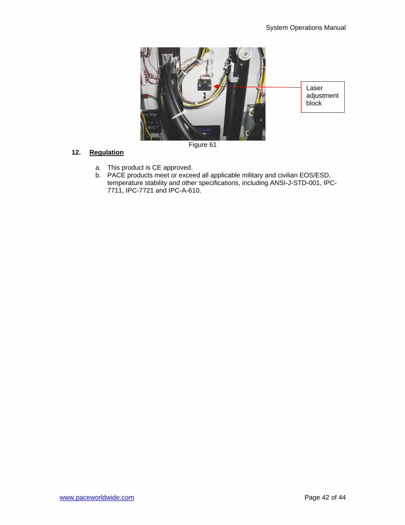
5. Laser alignment. This adjustment is necessary if, after spotting the PCB with the laser, the PCB is grossly out of alignment with the nozzle and camera viewing area. a. Pull out the camera housing. b. Orient a component on the PCB so it is centered in the viewing area. Make sure the camera is aligned with the nozzle first. (Step 2). c. Open the back of the TF 2500. WARNING: DO NOT TOUCH LIVE CIRCUITS! d. Loosen the 2 screws holding the laser mount. (Figure 60) e. Adjust the laser to a spot roughly in the center of the component and tighten screws.
Base Plate
Nest
Left adjustment
Mechanical stop
System Operations Manual
www.paceworldwide.com Page 42 of 44
Figure 61
12. Regulation
a. This product is CE approved. b. PACE products meet or exceed all applicable military and civilian EOS/ESD,
temperature stability and other specifications, including ANSI-J-STD-001, IPC-7711, IPC-7721 and IPC-A-610.
Laser adjustment block
System Operations Manual
www.paceworldwide.com Page 43 of 44
13. Service and Warranty
Please contact PACE or your local distributor for service and repair.
LIMITED WARRANTY Seller warrants to the first user that products manufactured by it and supplied hereunder are free of defects in materials and workmanship for a period of three (3) years from the date of receipt by such user. Blowers and motor pumps (which wear out during normal use) are warranted for a period of one (1) year. This warranty does not cover wear and tear under normal use, repair or replacement required as a result of misuse, improper application, mishandling or improper storage. Consumable items such as tips, heaters, filters, etc. which wear out under normal use are excluded. Failure to perform recommended routine maintenance, alterations or repairs made other than in accordance with Seller’s directions, or removal or alteration of identification plates in any way will void this warranty. This warranty is available only to the first user, but the exclusions and limitations herein apply to all persons and entities. SELLER MAKES NO OTHER WARRANTY, EXPRESS OR IMPLIED, AND MAKES NO WARRANTY OF MERCHANTABILITY OR FITNESS FOR A PARTICULAR PURPOSE. Seller will, at its option, repair or replace any defective products at its facility or other location approved by it at no charge to user, or provide parts without charge for installation by the user in the field at user’s expense and risk. User will be responsible for all costs of shipping equipment to Seller or other location for warranty service. EXCEPT FOR THE REMEDY ABOVE DESCRIBED, UNLESS OTHERWISE REQUIRED BY APPLICABLE LAW, SELLER WILL HAVE NO OTHER OBLIGATION WITH REGARD TO ANY BREACH OF WARRANTY OR OTHER CLAIM WITH RESPECT TO THE PRODUCTS, OR LIABILITY FOR ANY DIRECT, INDIRECT, CONSEQUENTIAL, OR INCIDENTAL LOSS OR DAMAGE CAUSED BY OR OCCURRING IN CONNECTION WITH ANY OF THE PRODUCTS. Warranty service may be obtained by contacting the appropriate PACE Company or local Authorized PACE distributor as set forth below to determine if return any item is required or, if repairs can be made, by the user in the field. Defective products may not be returned to PACE without a Service Authorization (“SA”) Number. Any warranty or other claim with respect to the products must be made in writing delivered to PACE (or local Authorized PACE distributor for Buyers outside the USA and the United Kingdom) within a reasonable time of the expiration date of this warranty with sufficient evidence of purchase and date of receipt, otherwise user’s rights under this warranty shall be deemed waived.

System Operations Manual
www.paceworldwide.com Page 44 of 44
www.paceworldwide.com
PACE USA PACE Europe 9030 Junction Drive Sherbourne House Annapolis Junction, MD 20701 Sherbourne Drive USA Tilbrook, Milton Keynes MK7 8HX United Kingdom Tel: (301) 490-9860 (44) 1908-277666 Fax: (301) 498-3252 (44) 1908-277777
PACE Incorporated retains the right to make changes to specifications contained herein at any time, without notice. Contact your local authorized PACE Distributor or PACE Incorporated to obtain the latest specifications. The following are trademarks and/or service marks of PACE, Incorporated, MD, USA:
INSTACAL™, FUMEFLO™, HEATWISE™, PACEWORLDWIDE™, PERMAGROUND™, POWERPORT™, POWERMODULE™, TEMPWISE™, TIP-BRITE™, AUTO-OFF™, and TEKLINK™.
The following are registered trademarks and/or service marks of PACE Incorporated, Annapolis Junction Maryland U.S.A.
ARM-EVAC®, FLO-D-SODR®, MINIWAVE®, PACE®, SENSATEMP®, SNAP-VAC®, SODRTEK®, SODR-X-TRACTOR®, THERMOFLO®, THERMOJET®, THERMOTWEEZ®, VISIFILTER®, THERMO-DRIVE®, and TOOLNET®.
PACE products meet or exceed all applicable military and civilian EOS/ESD, temperature stability and other specifications including MIL STD 2000, ANSI/JSTD 001, IPC7711, and IPC A-610.
Recommended