Author: Dirk Bertels
Hobart, November 12, 2004
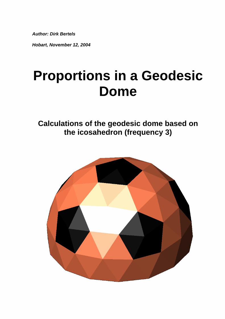
Proportions in a Geodesic Dome
Calculations of the geodesic dome based on the icosahedron (frequency 3)
Proportions in a Geodesic Dome Dirk Bertels
Index
INTRODUCTION ....................................................................................................................6
DEFINITIONS..........................................................................................................................7
STANDARDS USED IN THIS PAPER..................................................................................9 VECTORS .................................................................................................................................9 VERTICES AND POINTS .............................................................................................................9
Example ............................................................................................................................10 LINES.....................................................................................................................................10
THE ICOSAHEDRON ..........................................................................................................11 LENGTH OF THE ICOSAHEDRON EDGE....................................................................................13 LENGTH OF THE ICOSAHEDRON RADIUS.................................................................................13
APPROXIMATING THE SPHERE.....................................................................................14
FREQUENCY...........................................................................................................................14 CONVERTING THE ICOSAHEDRON TO A GEODESIC DOME ........................................................14
First step...........................................................................................................................14 Second step .......................................................................................................................15 Second step .......................................................................................................................16
DETAILED CALCULATIONS OF THE GEODESIC DOME ........................................17 STEP 1 - CALCULATING SECONDARY AND TERTIARY VERTEX COORDINATES AND RADII ON THE SURFACE OF AN ICOSAHEDRON .......................................................................................17
Locate the new vertices onto the 3-dimensional grid (calculate the coordinates). ..........17 STEP 2 - CALCULATING VERTICES ON THE GEODESIC DOME.................................................18 GEODESIC SPHERE COORDINATES FOR TRIANGLE AIJ...........................................................19 LENGTH OF GEODESIC DOME EDGES.....................................................................................20
ANGULAR INFORMATION ...............................................................................................21 LOCAL AXES ..........................................................................................................................21
DIHEDRAL ANGLES ...........................................................................................................22
ANGLE_DI_BB1 ANGLE BETWEEN 2 'B' EDGES INSIDE A ICOSAHEDRON TRIANGLE............22 ANGLE_DI_BB2 ANGLE BETWEEN 2 'B' EDGES JOINING 2 ICOSAHEDRON TRIANGLES ........24 ANGLE_DI_CC ANGLE BETWEEN 2 MEETING C EDGES......................................................25
Interlude ...........................................................................................................................25 ANGLE_DI_AA ANGLE BETWEEN 2 MEETING A EDGES ......................................................27 SUMMARY .............................................................................................................................28 ILLUSTRATIONS .....................................................................................................................29
DESIGNING ANIMATION OBJECTS...............................................................................30
APPLYING AN EVEN THICKNESS - BACKGROUND .................................................31 THE 'RUSSIAN DOLL' METHOD ..............................................................................................31 CENTERS OF A TRIANGLE .......................................................................................................32
1. Gravitational center .................................................................................................32
Page 2 of 76
Proportions in a Geodesic Dome Dirk Bertels
2. Orthocenter...............................................................................................................32 3. Circumradius ............................................................................................................32 4. In-center ...................................................................................................................33 5. Inner-radius system ..................................................................................................33
APPLYING AN EVEN THICKNESS ..................................................................................35 TRANSLATING THE PLANE......................................................................................................35 FINDING THE COORDINATES...................................................................................................35 EXAMPLE TRIANGLE BLOCK...................................................................................................35 PLANE EQUATIONS - GENERAL ..............................................................................................37
vector equation .................................................................................................................37 scalar equation .................................................................................................................37
THE ACF PLANE ...................................................................................................................38 Calculate the normal vector .............................................................................................38 Adding unit normal to plane ACF to get projected plane coordinates ............................39
EQUATION FOR THE AR - CL - FL PLANE................................................................................40 THE CBE PLANE....................................................................................................................41
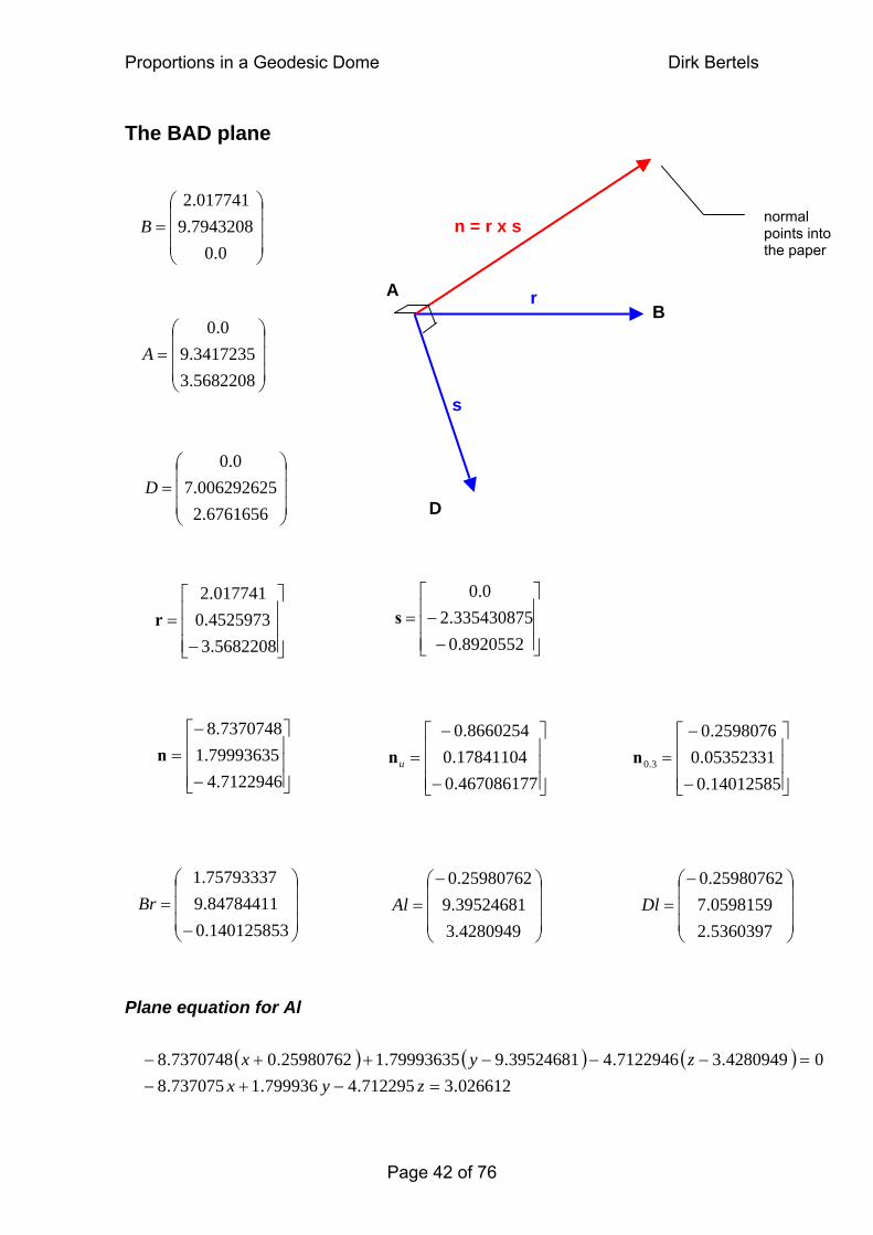
Plane equation for Bl........................................................................................................41 THE BAD PLANE ...................................................................................................................42
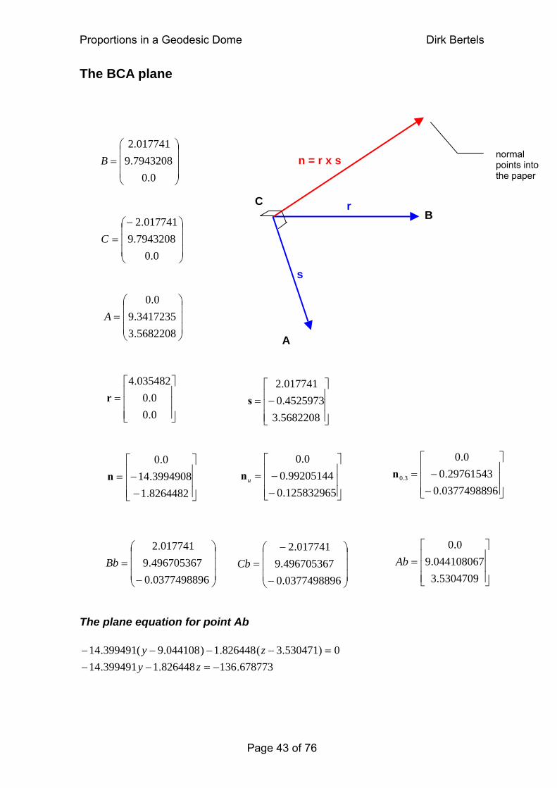
Plane equation for Al........................................................................................................42 THE BCA PLANE ...................................................................................................................42 THE BCA PLANE ...................................................................................................................43
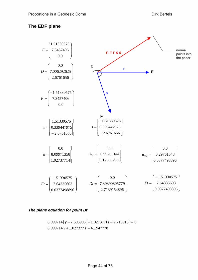
The plane equation for point Ab.......................................................................................43 THE EDF PLANE ....................................................................................................................43 THE EDF PLANE ....................................................................................................................44
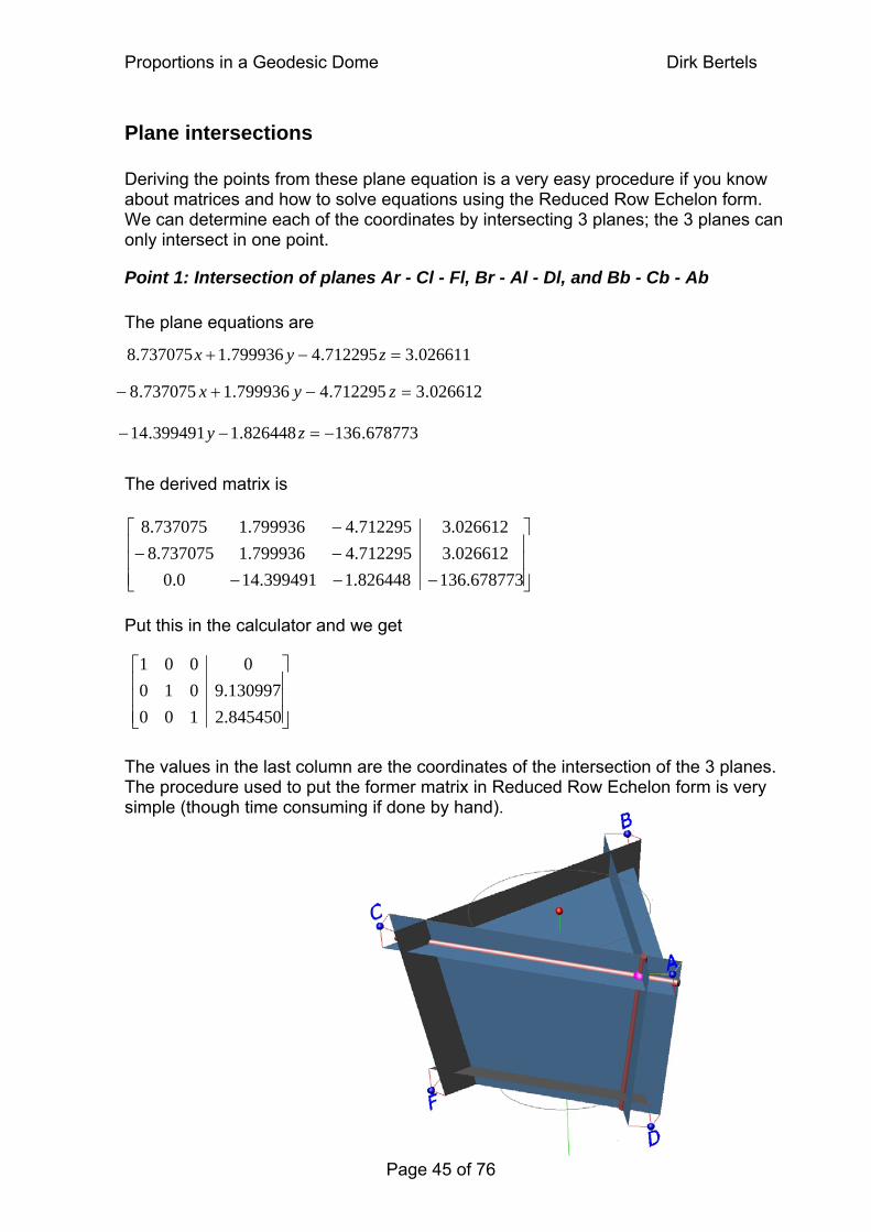
The plane equation for point Dt .......................................................................................44 PLANE INTERSECTIONS ..........................................................................................................45
Point 1: Intersection of planes Ar - Cl - Fl, Br - Al - Dl, and Bb - Cb - Ab .....................45 ILLUSTRATIONS .....................................................................................................................46 CALCULATING THE RADIAL ANGLE BETWEEN 2 VERTICES - GENERAL EQUATION ..................48
angle_A_Yaxis ..................................................................................................................48 angle_AIJ_Yaxis = 0.364864 radians ..............................................................................49 angle_A_AIJ = 0.652358 radians ....................................................................................49 angle_A_DJI = 1.38209 radians......................................................................................49 angle_A_DGJ = 1.75951 radians ....................................................................................49 angle_A_CGD = 2.48923 radians ...................................................................................49
EDGE-RADIAL ANGLES ....................................................................................................50
SUPPLEMENT 1 - CLASSIFICATION / NOMENCLATURE ........................................51
Edges ................................................................................................................................51 Chords[over edge]............................................................................................................51 Angle[chord,edge]............................................................................................................51
SUPPLEMENT 2 - EQUATION CELLS.............................................................................52 NON - NORMALISED VERTICES...............................................................................................52
IP - Icosahedron Primary Vertices...................................................................................52 IS - Icosahedron Secondary Vertices (adjacent to a Primary Vertex) .............................52 IT - Icosahedron Tertiary Vertices (adjacent to Secondary Vertices)..............................52
NORMALISED VERTICES ........................................................................................................53 SP - Spherical Primary Vertices (normalised) .................................................................53
Page 3 of 76
Proportions in a Geodesic Dome Dirk Bertels
SS - Spherical Secondary Vertices (normalised)..............................................................53 ST - Spherical Tertiary Vertices (normalised) .................................................................53
SUPPLEMENT 3 - VERTEX TABLES ...............................................................................54
SUPPLEMENT 4 - CLASSIFICATION AND COMPARISON OF SECONDARY AND TERTIARY VERTEX COORDINATES.............................................................................58
SUPPLEMENT 5 - USEFUL EQUATIONS........................................................................59
1. Equation to measure a distance between 2 vertices in 3D. ......................................59 2. General equation to locate a point at a ratio of v/w of the length between two vertices, starting from the first vertex...............................................................................59 3. Law of cosines ..........................................................................................................59 4. Law of sines ..............................................................................................................59 4. Length of chord spanning an arc of given length.....................................................59 5. Angle between two points in 2D, given the chord length .........................................60 6. Height of a BCC triangle,.........................................................................................60 7. Find center of any triangle .......................................................................................60 8. Calculate the angle in radians between 2 vectors starting at the origin..................60 9. Calculate the inner circle coordinates of a triangle.................................................60 10. The dot product of 2 vectors .................................................................................61 11. Cross product of 2 vectors (using determinant system) .......................................61
SUPPLEMENT 6 - CALCULATIONS FOR AEI TRIANGLE ........................................62
"Flat " Coordinates (on the surface of the icosahedron) .................................................62 Normalised coordinates....................................................................................................63
SUPPLEMENT 7 - CALCULATIONS FOR ABE TRIANGLE .......................................64
"Flat " Coordinates ..........................................................................................................64 Normalised coordinates....................................................................................................65
SUPPLEMENT 8 - CALCULATE ANGLES IN 3D...........................................................66 GENERAL...............................................................................................................................66 PROCEDURE...........................................................................................................................66
SUPPLEMENT 9 - SPHERICAL COORDINATES ..........................................................67
SUPPLEMENT 9 - SPHERICAL COORDINATES ..........................................................68
Standard representation of a point using spherical coordinates .....................................68 In the Y-r plane In the Z-X plane................................................................................68 Spherical to rectangular Rectangular to Spherical...................................................68
SUPPLEMENT 10 - ILLUSTRATIONS..............................................................................69
PLATONIC SOLIDS..................................................................................................................69 THE ICOSAHEDRON................................................................................................................69 THE ACTUAL GEODESIC DOME, FREQUENCY 3, SIZE 5/8........................................................70 FULL GEODESIC DOME - FREQUENCY 3 - 'ROD' OR 'STICK' VIEW............................................71
ANIMATION IMAGES.........................................................................................................72
BCC TRIANGLE FACE DIMENSIONS.............................................................................74
Page 4 of 76
Proportions in a Geodesic Dome Dirk Bertels
BAA TRIANGLE FACE DIMENSIONS.............................................................................75
GENERAL NOTES................................................................................................................76 NUMBER OF HEXAGONS, PENTAGONS, TRIANGLES NEEDED PER DOME ..................................76
Sphere ...............................................................................................................................76 5/8 dome ...........................................................................................................................76
Page 5 of 76
Proportions in a Geodesic Dome Dirk Bertels
Introduction This paper has co-evolved alongside a computer program I wrote to simulate the building of a dome using one building block, the triangular block. It aims to clarify the various mathematical concepts involved in building this type of geodesic dome, emphasising the various geometric proportions present within. Knowing these proportions will provide us with a solid foundation to the design of any form of dome construction, be it concrete (dome buildings), virtual (animation), or purely in the abstract for the theorists… The word dome will be used throughout this text in its most general form, that is, it may be whatever part of the geodesic sphere, including the whole sphere. In terms of this program, the whole sphere as well as part of the sphere is produced in very much the same way… Whereas in an actual (physical) dome building some deviation from the ideal measurements is acceptable, animation requires theoretical precision and versatility. For example, it should be possible to change dimensions easily (such as changing the thickness of the building block walls). Quite a lot of information could be found on the web regarding measurements of the geodesic dome, but I was more interested in the equations these measurements were derived from, for exactly the reason given above: it gives you the versatility to change dimensions. Additionally, seeing the equations helps the understanding of the geometry involved and also gives you some insight into the beauty of geometry. Don't be intimidated by the size of some of the equations, if you follow the logic it will soon become apparent that the calculations involved are actually quite simple. As stated before, the animation simulates the construction of a dome, starting with one building block. Although animation involves programming, no programming language is used in this paper, only the mathematical description on which the procedures are based. Moreover, the description is elementary, using basic trigonometry and 3D geometry, and thus easy to follow for any form of application… In fact the procedural logic used in programming may help the understanding of the subject for programmers and non-programmers alike.1
The methods used in the program are mentioned nevertheless to use as reference to the program, which, after all, is the reason this text came about. To gain a good grasp on the topic it will be necessary to picture the icosahedron and the geodesic sphere (or dome) in 3D. Much has been written about this, and a general search will greatly benefit the understanding of these 3D objects. This being said, a lot of effort has been spent on clarification and supplementing information, even on a basic level.
1 My particular animation project is written in C++ and uses the OpenGl libraries.
Page 6 of 76
Proportions in a Geodesic Dome Dirk Bertels
Definitions Interestingly, a sphere is a mathematical object that contains the maximum volume compared to its surface area, so if a structure of large volume is to be constructed for minimum cost, it makes sense to look at structures whose shape approaches a sphere2. The word geodesic is derived from the Latin for earth dividing. More specifically, geodesic is another word for great circle. A great circle is the largest circle that can be drawn around a sphere, like the lines of latitude. The shortest path between 2 points on the surface of a sphere always runs along a geodesic. The Wolfram (writer of the infamous program Mathematica) web page defines the geodesic dome as a
triangulation of a Platonic solid or other polyhedron to produce a close approximation to a sphere or hemisphere3.
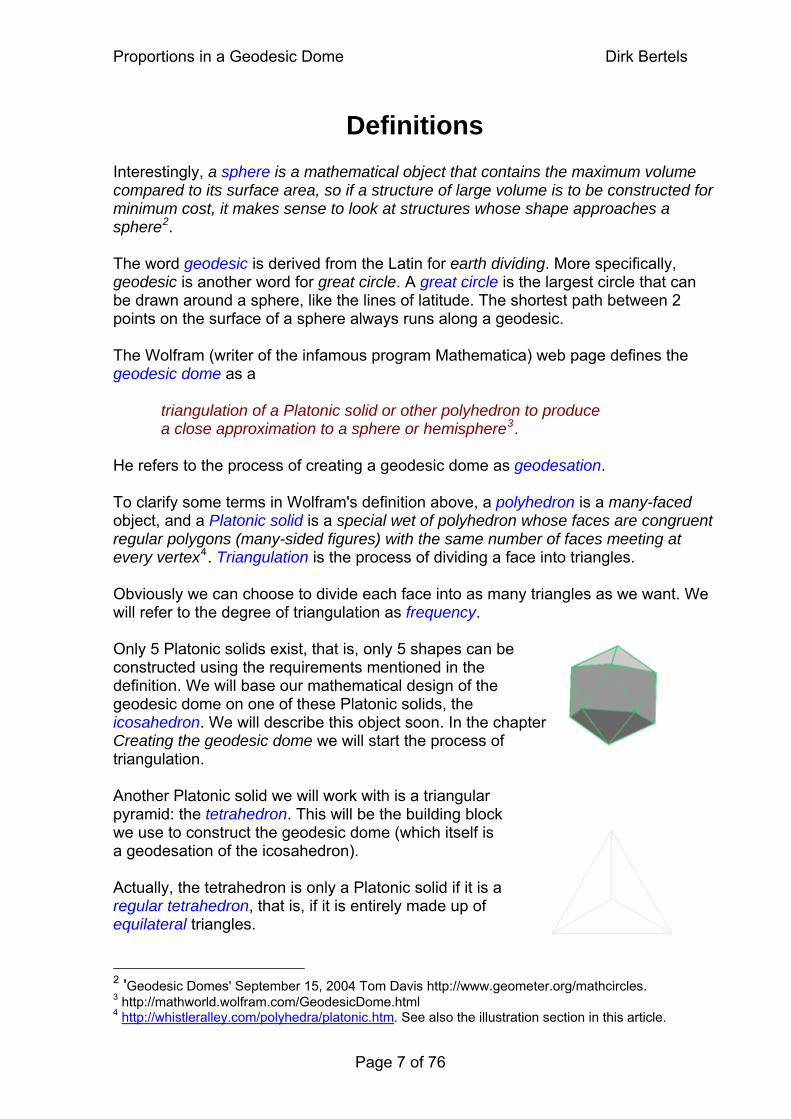
He refers to the process of creating a geodesic dome as geodesation. To clarify some terms in Wolfram's definition above, a polyhedron is a many-faced object, and a Platonic solid is a special wet of polyhedron whose faces are congruent regular polygons (many-sided figures) with the same number of faces meeting at every vertex4. Triangulation is the process of dividing a face into triangles. Obviously we can choose to divide each face into as many triangles as we want. We will refer to the degree of triangulation as frequency. Only 5 Platonic solids exist, that is, only 5 shapes can be constructed using the requirements mentioned in the definition. We will base our mathematical design of the geodesic dome on one of these Platonic solids, the icosahedron. We will describe this object soon. In the chapter Creating the geodesic dome we will start the process of triangulation. Another Platonic solid we will work with is a triangular pyramid: the tetrahedron. This will be the building block we use to construct the geodesic dome (which itself is a geodesation of the icosahedron). Actually, the tetrahedron is only a Platonic solid if it is a regular tetrahedron, that is, if it is entirely made up of equilateral triangles. 2 'Geodesic Domes' September 15, 2004 Tom Davis http://www.geometer.org/mathcircles.3 http://mathworld.wolfram.com/GeodesicDome.html 4 http://whistleralley.com/polyhedra/platonic.htm. See also the illustration section in this article.
Page 7 of 76
Proportions in a Geodesic Dome Dirk Bertels
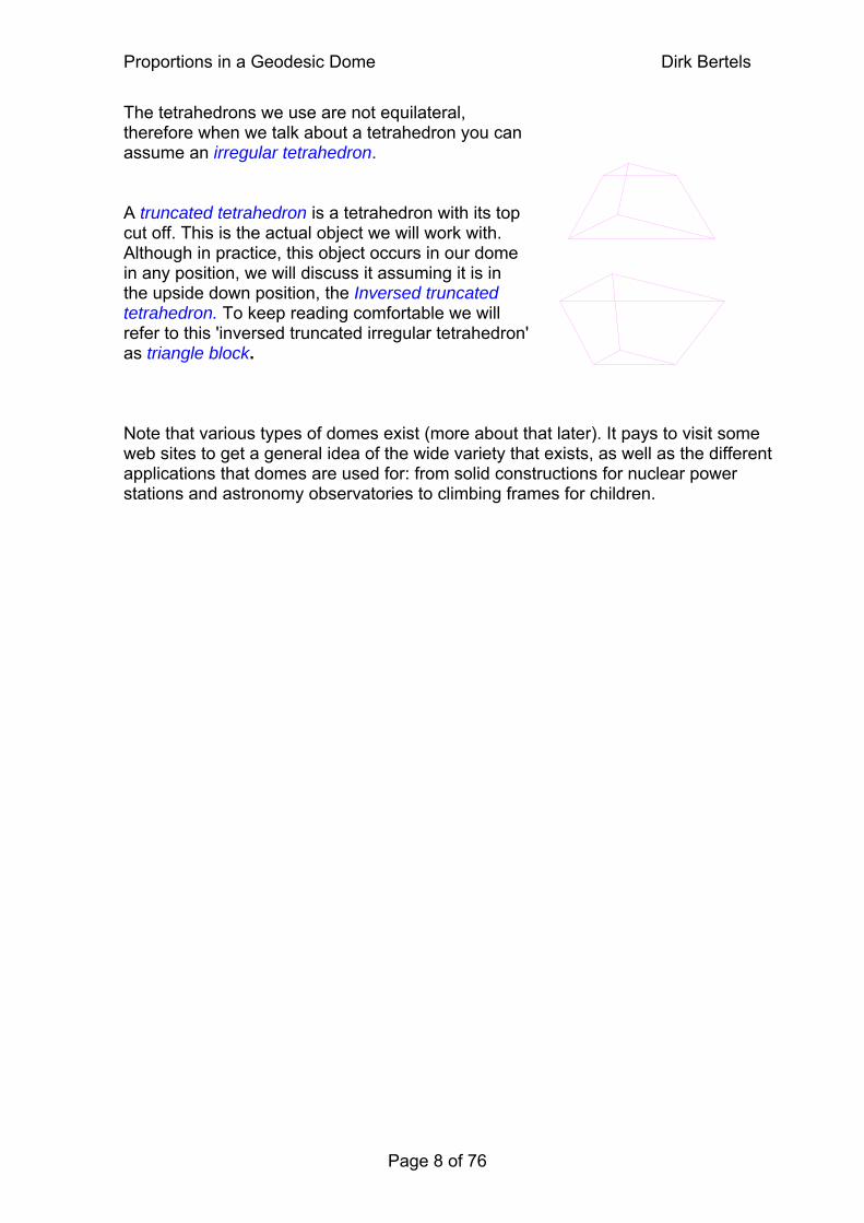
The tetrahedrons we use are not equilateral, therefore when we talk about a tetrahedron you can assume an irregular tetrahedron. A truncated tetrahedron is a tetrahedron with its top cut off. This is the actual object we will work with. Although in practice, this object occurs in our dome in any position, we will discuss it assuming it is in the upside down position, the Inversed truncated tetrahedron. To keep reading comfortable we will refer to this 'inversed truncated irregular tetrahedron' as triangle block. Note that various types of domes exist (more about that later). It pays to visit some web sites to get a general idea of the wide variety that exists, as well as the different applications that domes are used for: from solid constructions for nuclear power stations and astronomy observatories to climbing frames for children.
Page 8 of 76
Proportions in a Geodesic Dome Dirk Bertels
Standards used in this paper
Vectors I like to use the standard used in many mathematics text books5. This simply prints the vectors in bold. Unless otherwise stated, all vectors are assumed having their origin at the world origin. Therefore,
A = 0_A
Note how we use the underscore to relate two variables to each other. Vectors are used to indicate both magnitude and direction. While in engineering and other sciences this characteristic is greatly exploited to describe physical phenomena, for our purposes we mainly use vectors to indicate and calculate position. So it could be argued, why bother, just use the point (coordinate) notation. So we could, but if we consider the coordinates of a point in relation to the world origin we have more information, such as location, direction, distance from origin. This allows us to do more calculations. And vectors are the means to do these calculations. It is worthwhile to study vectors and matrices since they are a fundamental concept in the field of graphics and animation. [link to supplement primer on vectors]
Vertices and points We can use the vector (matrix) notation to indicate a vertex. The real interpretation of this is the vector from the world origin to the point.
The letter U (from 'universal') will be used to indicate a general group of vertices. So if we see something like Ut in an equation, and we know there are 3 't' vertices (AIJt, IJ1t, and IJ2t) then this equation holds true for those 3 vertices. However, in calculating vertices, it is often necessary to apply equations to each of the coordinates of a point. In this regard, vertices are looked upon as points with a set of coordinates. So in equations where vector coordinates are calculated we use
where i is the index representing x, y, and z in turn. Each time we need to define a point in 3D space we need to calculate the x, y, and z coordinates of this point.
=coordinatezcoordinatey
x
__U
⎥⎥⎥
⎦
⎤
⎢⎢⎢
⎣
⎡ coordinate_
[ ]iU
5 e.g. 'Calculus' by James Stewart ISBN0-534-35949-3
Page 9 of 76
Proportions in a Geodesic Dome Dirk Bertels
Example Assuming there are 3 types of 't' vertices; AIJt, IJ1t, and IJ2t, then the equation
[ ] [ ] )_1(* factorlengthUUt ii −=
is the general equation for AIJt
AIJt IJ IJ IJ IJ IJ IJ And so it comes to pass that we often represent the vertices in point notation while we treat them as vectors in the calculations. Never mind …
Lines To indicate a line from one vertex to another, we use …
Where A and B are vertices. We will use the same notation to indicate a vector from point A to B. To indicate the length of a line, use the absolute notation
[ ] [ ] )_1(*22 factorlengthIJt zz −=
[ ] [ ] )_1(*22 factorlengthIJt yy −=
[ ] [ ] )_1(*22 factorlengthIJt xx −=
[ ] [ ] )_1(*11 factorlengthIJt zz −=
[ ] [ ] )_1(*11 factorlengthIJt yy −=
[ ] [ ] )_1(*11 factorlengthIJt xx −=
[ ] [ ] )_1(* factorlengthAIJ zz −=
[ ] [ ] )_1(* factorlengthAIJ yyAIJt −=
[ ] [ ] )_1(* factorlengthAIJ xx =
_
−
A B
BA _
Page 10 of 76
Proportions in a Geodesic Dome Dirk Bertels
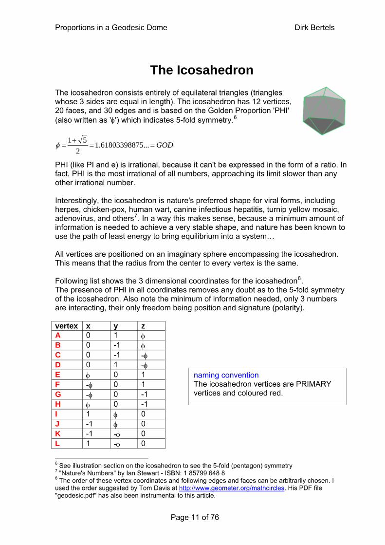
The Icosahedron The icosahedron consists entirely of equilateral triangles (triangles whose 3 sides are equal in length). The icosahedron has 12 vertices, 20 faces, and 30 edges and is based on the Golden Proportion 'PHI' (also written as 'φ') which indicates 5-fold symmetry.6
GOD==+
= ...56180339887.12
51 φ PHI (like PI and e) is irrational, because it can't be expressed in the form of a ratio. In fact, PHI is the most irrational of all numbers, approaching its limit slower than any other irrational number. Interestingly, the icosahedron is nature's preferred shape for viral forms, including herpes, chicken-pox, human wart, canine infectious hepatitis, turnip yellow mosaic, adenovirus, and others7. In a way this makes sense, because a minimum amount of information is needed to achieve a very stable shape, and nature has been known to use the path of least energy to bring equilibrium into a system… All vertices are positioned on an imaginary sphere encompassing the icosahedron. This means that the radius from the center to every vertex is the same. Following list shows the 3 dimensional coordinates for the icosahedron8. The presence of PHI in all coordinates removes any doubt as to the 5-fold symmetry of the icosahedron. Also note the minimum of information needed, only 3 numbers are interacting, their only freedom being position and signature (polarity). vertex x y z A 0 1 φ B 0 -1 φ C 0 -1 -φ D 0 1 -φ E φ 0 1 F -φ 0 1 G -φ 0 -1 H φ 0 -1 I 1 φ 0 J -1 φ 0 K -1 -φ 0 L 1 -φ 0
naming convention The icosahedron vertices are PRIMARY vertices and coloured red.
6 See illustration section on the icosahedron to see the 5-fold (pentagon) symmetry 7 "Nature's Numbers" by Ian Stewart - ISBN: 1 85799 648 8 8 The order of these vertex coordinates and following edges and faces can be arbitrarily chosen. I used the order suggested by Tom Davis at http://www.geometer.org/mathcircles. His PDF file "geodesic.pdf" has also been instrumental to this article.
Page 11 of 76
Proportions in a Geodesic Dome Dirk Bertels
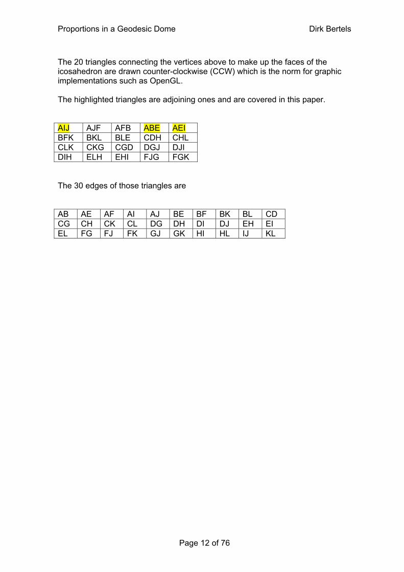
The 20 triangles connecting the vertices above to make up the faces of the icosahedron are drawn counter-clockwise (CCW) which is the norm for graphic implementations such as OpenGL. The highlighted triangles are adjoining ones and are covered in this paper. AIJ AJF AFB ABE AEI BFK BKL BLE CDH CHL CLK CKG CGD DGJ DJI DIH ELH EHI FJG FGK The 30 edges of those triangles are AB AE AF AI AJ BE BF BK BL CD CG CH CK CL DG DH DI DJ EH EI EL FG FJ FK GJ GK HI HL IJ KL
Page 12 of 76
Proportions in a Geodesic Dome Dirk Bertels
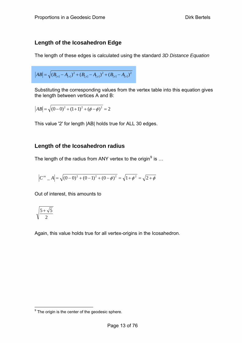
Length of the Icosahedron Edge The length of these edges is calculated using the standard 3D Distance Equation
2][][
2][][
2][][ )()()( AAAB +−+−= zzyyxx ABBB −
Substituting the corresponding values from the vertex table into this equation gives the length between vertices A and B:
2)()11()00( 222 =−+++−= φφAB
This value '2' for length |AB| holds true for ALL 30 edges.
Length of the Icosahedron radius The length of the radius from ANY vertex to the origin9 is …
φφφ +=+=−+−+−= 21)0()10()00(_ 2222AreC Out of interest, this amounts to
255 +
Again, this value holds true for all vertex-origins in the Icosahedron.
9 The origin is the center of the geodesic sphere.
Page 13 of 76
Proportions in a Geodesic Dome Dirk Bertels
Creating the geodesic dome
Approximating the sphere As mentioned above, there are many types of geodesic domes. They may be based on other polyhedrons, or even a combination of polyhedrons. And any of these can exist in different frequencies (see below). In addition, they may be of different sizes (whole sphere, half sphere, 5/8 of a sphere, etc). The geodesic sphere, based on the icosahedron is actually commonly used in graphics applications to approximate a sphere because of the minimum amount of information that is needed to create the polygons necessary.10 However, these applications use frequencies that are powers of two…
Frequency The term frequency has been mentioned several times now. It relates to the subdivision of the polyhedron's edges in such a way that a number of triangular faces are created (remember that a geodesic dome is a triangulation of a polyhedron, that is, the polyhedron gets subdivided into triangles). The newly created vertices are then pushed upwards against an imaginary sphere encompassing this polygon. This way the sphere is approximated at a higher resolution, since more (smaller) faces are describing the sphere. This paper discusses the sphere (dome) created by subdividing the edges of the icosahedron by 3 (hence, frequency 3). The graphics application mentioned above recursively divides the sides by two (which is easier to implement), thereby approximating a sphere closer and closer to a higher resolution as the frequency exponentially grows… In order to convert the icosahedron to a dome, two steps are taken11…
Converting the icosahedron to a geodesic dome
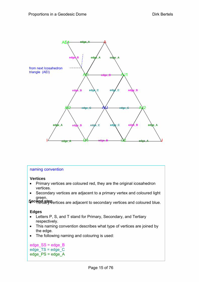
First step Divide all 30 edges of the icosahedron by 3. Following that, the newly derived vertices are connected in such a way that each icosahedron triangle consists of 9 sub-triangles (see diagram below and figure in the illustration section). For now, though differently named, all edges have the same length. One icosahedron triangle is chosen for our calculations. Remember that we are after proportions, therefore the proportions in this one triangle will be reflected in the other 11 triangles of the icosahedron.
10 See the "redbook", a free standard openGL tutorial on the web, 2nd chapter. 11 Another method that converts the icosahedron to a geodesic dome truncates (cuts the tips off) the icosahedron first and consequently triangulates the faces with a frequency of 1.
Page 14 of 76
Proportions in a Geodesic Dome Dirk Bertels
AI1
AJ2
AJ1
I J
A
AIJ AI2
IJ1 IJ2
AE1
edge_A edge_A
edge_A
edge_A edge_A
edge_A
edge_A
from next Icosahedron triangle (AEI)
edge_B
edge_Bedge_B
edge_B
edge_B
edge_B
edge_B
edge_C
edge_C
edge_C
edge_C
edge_C edge_C
Second step
naming convention Vertices • Primary vertices are coloured red, they are the original icosahedron
vertices. • Secondary vertices are adjacent to a primary vertex and coloured light
green. • Tertiary vertices are adjacent to secondary vertices and coloured blue. Edges • Letters P, S, and T stand for Primary, Secondary, and Tertiary
respectively. • This naming convention describes what type of vertices are joined by
the edge. • The following naming and colouring is used: edge_SS = edge_B edge_TS = edge_C edge_PS = edge_A
Page 15 of 76
Proportions in a Geodesic Dome Dirk Bertels
Second step Each of these newly created vertices is pushed against the encompassing sphere so their radii equal the length of the icosahedron's vertex-origin radius. This explains why the edges on the diagrams are named differently, because their lengths become different. The vertices do not lie on a flat triangle anymore, but on a wing-shaped 3D triangle.12
Following is a more detailed description of the two steps taken in constructing the dome…
12 See the diagram depicting the 5/8 dome in the illustration section.
Page 16 of 76
Proportions in a Geodesic Dome Dirk Bertels
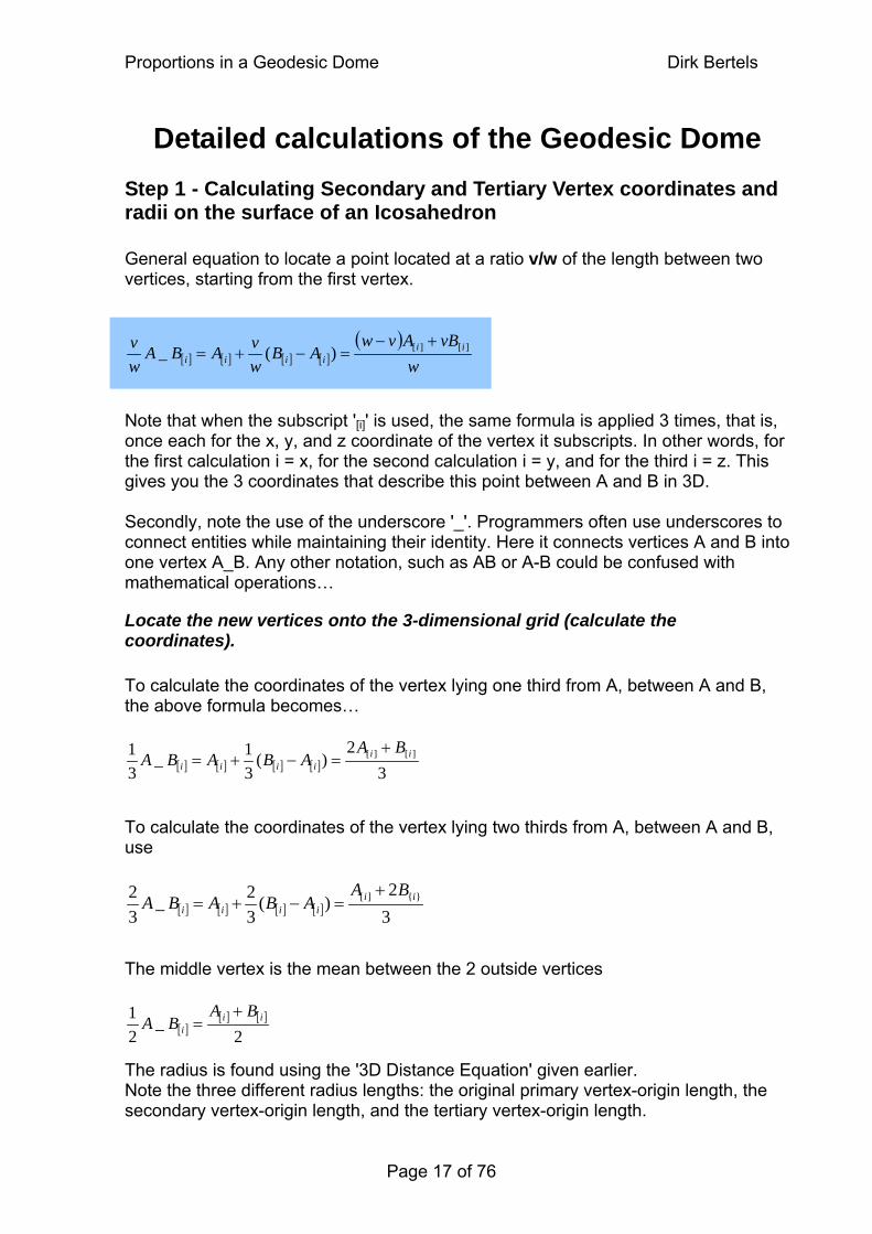
Detailed calculations of the Geodesic Dome Step 1 - Calculating Secondary and Tertiary Vertex coordinates and radii on the surface of an Icosahedron General equation to locate a point located at a ratio v/w of the length between two vertices, starting from the first vertex. ( ) [ ] [ ] [ ] [ ]
Note that when the subscript '[i]' is used, the same formula is applied 3 times, that is, once each for the x, y, and z coordinate of the vertex it subscripts. In other words, for the first calculation i = x, for the second calculation i = y, and for the third i = z. This gives you the 3 coordinates that describe this point between A and B in 3D. Secondly, note the use of the underscore '_'. Programmers often use underscores to connect entities while maintaining their identity. Here it connects vertices A and B into one vertex A_B. Any other notation, such as AB or A-B could be confused with mathematical operations…
Locate the new vertices onto the 3-dimensional grid (calculate the coordinates). To calculate the coordinates of the vertex lying one third from A, between A and B, the above formula becomes… To calculate the coordinates of the vertex lying two thirds from A, between A and B, use The middle vertex is the mean between the 2 outside vertices The radius is found using the '3D Distance Equation' given earlier. Note the three different radius lengths: the original primary vertex-origin length, the secondary vertex-origin length, and the tertiary vertex-origin length.
wvBAvw
Bw
iiiiii
][][)(_+−
−+= AvABAv=
w
[ ] [ ] [ ] [ ] 32
)(31_ ][][ ii
iiii
BAABABA
+=−+=
13
[ ] [ ] [ ] [ ] 32
)(32_ }{][ ii
iiii
BAABABA
+2=−+=
3
[ ][ ] [ ]
2_ ii
i
BABA
+=
12
Page 17 of 76
Proportions in a Geodesic Dome Dirk Bertels
vertex x y z radius approx. radius A 0 1 φ 2+φ 1.902113032
AI1 31
32 φ+
32φ
910
+φ 1.652012439
AJ1 31
− 3
2 φ+ 3
2φ 9
10+φ
AI2 32
321 φ+
3φ
910
+φ
AIJ 0 321 φ+
3φ
32
+φ 1.511522628
AJ2 32
− 321 φ+
3φ
910
+φ
I 1 φ 0 2+φ
IJ1 31 φ 0
910
+φ
IJ2 31
− φ 0
910
+φ
J -1 φ 0 2+φ
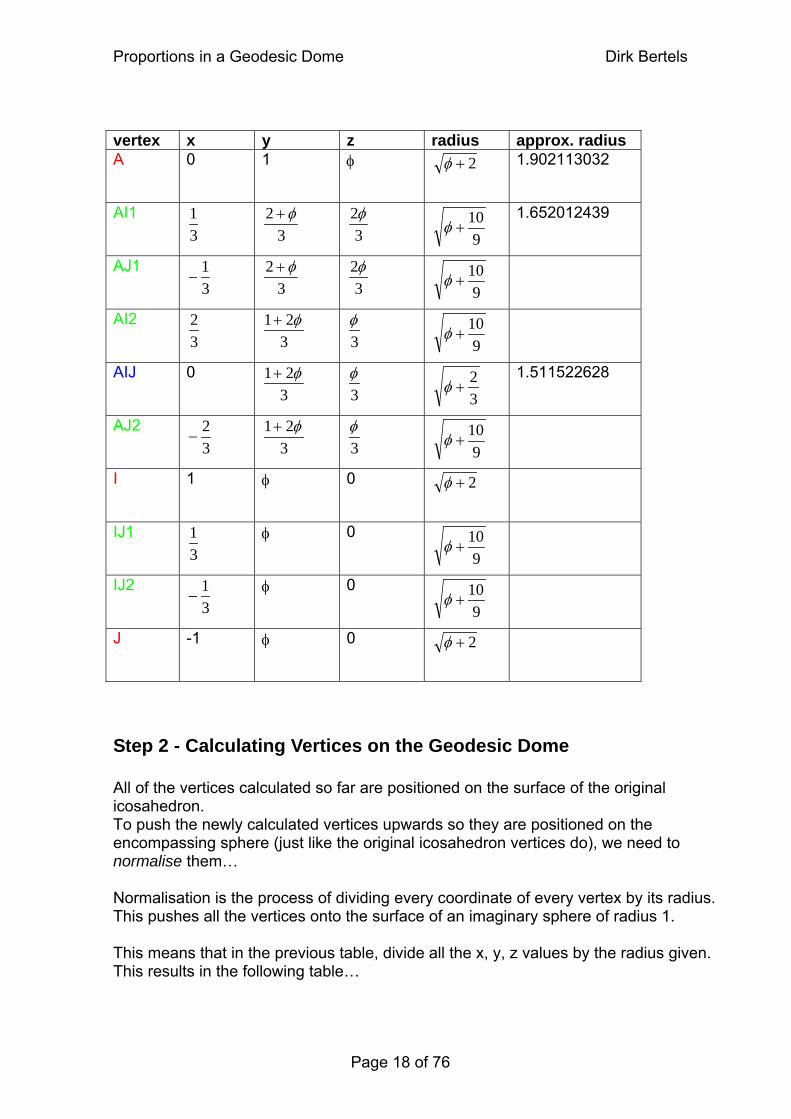
Step 2 - Calculating Vertices on the Geodesic Dome All of the vertices calculated so far are positioned on the surface of the original icosahedron. To push the newly calculated vertices upwards so they are positioned on the encompassing sphere (just like the original icosahedron vertices do), we need to normalise them… Normalisation is the process of dividing every coordinate of every vertex by its radius. This pushes all the vertices onto the surface of an imaginary sphere of radius 1. This means that in the previous table, divide all the x, y, z values by the radius given. This results in the following table…
Page 18 of 76
Proportions in a Geodesic Dome Dirk Bertels
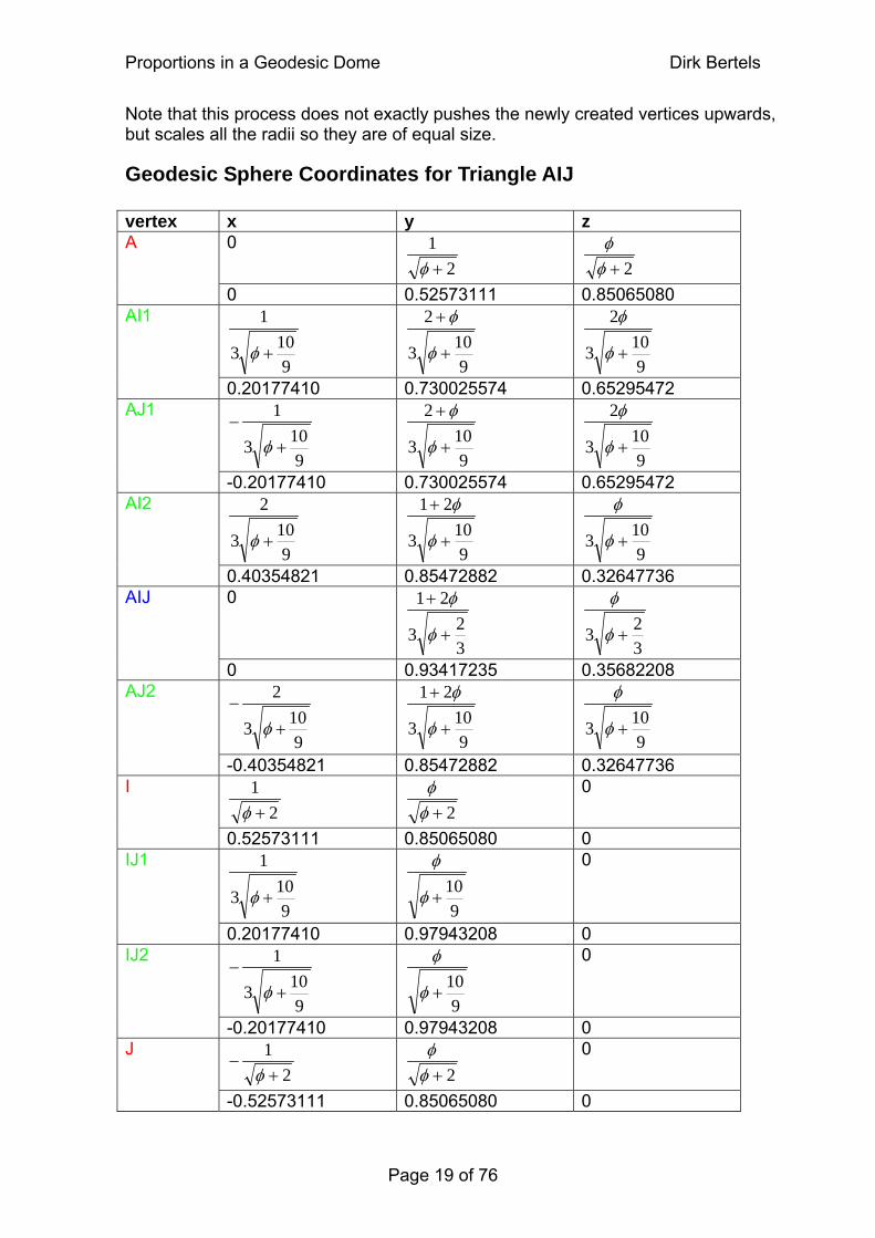
Note that this process does not exactly pushes the newly created vertices upwards, but scales all the radii so they are of equal size.
Geodesic Sphere Coordinates for Triangle AIJ vertex x y z
0 2
1+φ
2+φ
φ A
0 0.52573111 0.85065080
9103
1
+φ
9103
2
+
+
φ
φ
9103
2
+φ
φ AI1
0.20177410 0.730025574 0.65295472
9103
1
+−
φ
9103
2
+
+
φ
φ
9103
2
+φ
φ AJ1
-0.20177410 0.730025574 0.65295472
9103
2
+φ
9103
21
+
+
φ
φ
9103 +φ
φ AI2
0.40354821 0.85472882 0.32647736 0
323
21
+
+
φ
φ
323 +φ
φ AIJ
0 0.93417235 0.35682208
9103
2
+−
φ
9103
21
+
+
φ
φ
9103 +φ
φ AJ2
-0.40354821 0.85472882 0.32647736
21+φ
2+φ
φ 0 I
0.52573111 0.85065080 0
9103
1
+φ
910
+φ
φ 0 IJ1
0.20177410 0.97943208 0
9103
1
+−
φ
910
+φ
φ 0 IJ2
-0.20177410 0.97943208 0
21+
−φ
2+φ
φ 0 J
-0.52573111 0.85065080 0
Page 19 of 76
Proportions in a Geodesic Dome Dirk Bertels
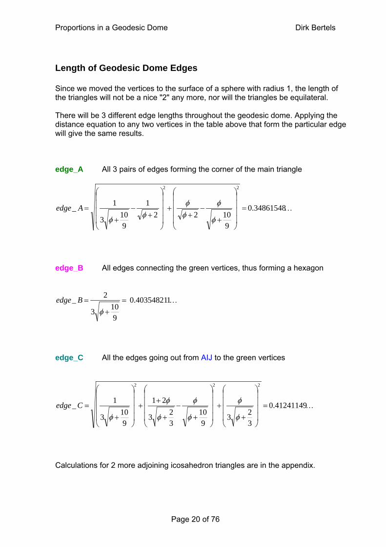
Length of Geodesic Dome Edges Since we moved the vertices to the surface of a sphere with radius 1, the length of the triangles will not be a nice "2" any more, nor will the triangles be equilateral. There will be 3 different edge lengths throughout the geodesic dome. Applying the distance equation to any two vertices in the table above that form the particular edge will give the same results. edge_A All 3 pairs of edges forming the corner of the main triangle
…=⎟⎟⎟⎟
⎠
⎞
⎜⎜⎜⎜
⎝
⎛
+−
++
⎟⎟⎟⎟
⎠
⎞
⎜⎜⎜⎜
⎝
⎛
+−
+= 0.34861548
91022
1
9103
1_
22
φ
φφφ
φφA
edge
edge_B All edges connecting the green vertices, thus forming a hexagon
…=+
= 10.40354821
9103
2_φ
B edge edge_C All the edges going out from AIJ to the green vertices
…=⎟⎟⎟⎟
⎠
⎞
⎜⎜⎜⎜
⎝
⎛
++
⎟⎟⎟⎟
⎠
⎞
⎜⎜⎜⎜
⎝
⎛
+−
+
++
⎟⎟⎟⎟
⎠
⎞
⎜⎜⎜⎜
⎝
⎛
+= 0.41241149
323
910
323
21
9103
1_
222
φ
φ
φ
φ
φ
φ
φC
edge
Calculations for 2 more adjoining icosahedron triangles are in the appendix.
Page 20 of 76
Proportions in a Geodesic Dome Dirk Bertels
Angular Information So far we have derived vertex coordinates and the three types of edges of the geodesic dome. But there is more information to be found, such as the various angles present. There are 2 main types of angles, the radial angles (angle between two radii) and the dihedral angles (angle between two faces (triangles)). The dihedral angles will be discussed first. In fact this information is NOT used in the animation, since the location of the object's vertices are used to construct the object. However, the angular information will be needed for more practical purposes where physical construction is required. The radial angles are discussed later as they are needed to build the actual dome from the hexagons. The program actually calculates all these values in geodome_print_values.cpp exactly for this purpose. It prints them out on a separate console alongside the actual animation. Note that at his stage it becomes necessary to have a good picture of the physical dome. It is very helpful (and entertaining) to construct a model out of cardboard, and marking the vertices with the names used in this paper. The vertex, edge, and triangle tables should hold enough information to enable you to do this. You can multiply the above found values for the edges with any number you like (as long as all 3 edges are multiplied by the SAME value). This is possible because the numbers are actually relative to a radius of one. If for example you like a dome with radius of 10 cm, just multiply the length of the edges by 10…
Local axes The whole world of animation exists in a global coordinate system whose three directions are referred to as world axes. Animation objects existing in this world have their own local coordinate system, depicted by local axes13. To enable us to orientate the geodesic dome in animation, it is necessary to know where the geodesic sphere cuts the local axes. This naturally depends on how the coordinates were ordered and named in the first place and is therefore only applicable to this particular situation. y axis Cuts from below through the center of edge_KL1_KL2 upwards through the center of edge_IJ1_IJ2 x axis Cuts from the left through the center of edge_FG1_FG2 rightwards through the center of edge_EH1_EH2 z axis Cuts from the back through the center of edge_CD1_CD2 forwards through the center of edge_AB1_AB2 13 Refer to the "Spherical coordinates" supplementary section to see the naming and orientation of the local coordinate system we use.
Page 21 of 76
Proportions in a Geodesic Dome Dirk Bertels
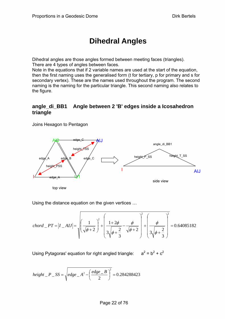
Dihedral Angles Dihedral angles are those angles formed between meeting faces (triangles). There are 4 types of angles between faces. Note in the equations that if 2 variable names are used at the start of the equation, then the first naming uses the generalised form (t for tertiary, p for primary and s for secondary vertex). These are the names used throughout the program. The second naming is the naming for the particular triangle. This second naming also relates to the figure.
angle_di_BB1 Angle between 2 'B' edges inside a Icosahedron triangle Joins Hexagon to Pentagon AIJ AI2
IJ1
edge_A
edge_A
edge_C
edge_C
0.64085182
3232
323
212
1__
22
2
=⎟⎟⎟⎟
⎠
⎞
⎜⎜⎜⎜
⎝
⎛
++
⎟⎟⎟⎟
⎠
⎞
⎜⎜⎜⎜
⎝
⎛
+−
+
++⎟
⎟⎠
⎞⎜⎜⎝
⎛
+==
φ
φφφ
φ
φφ
AIJIPTchord
Using the distance equation on the given vertices …
Using Pytagoras' equation for right angled triangle: a2 = b2 + c2
I
edge_B
height_TSS
height_PSS
height_P_SS height_T_SS
AIJ
angle_di_BB1
side view
top view
I
30.28428842 2
____2
2 =⎟⎠⎞
⎜⎝⎛−=
BedgeAedgeSSPheight
Page 22 of 76
Proportions in a Geodesic Dome Dirk Bertels
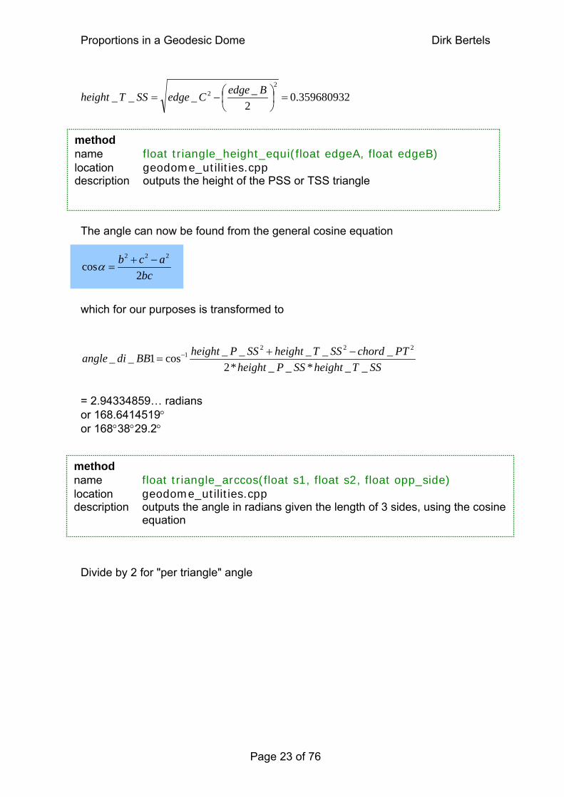
20.35968093 2
____2
2 =⎟⎠⎞
⎜⎝⎛−=
BedgeCedgeSSTheight
method name float triangle_arccos(float s1, float s2, float opp_side) location geodome_utilities.cpp description outputs the angle in radians given the length of 3 sides, using the cosine
equation
method name float triangle_height_equi(float edgeA, float edgeB) location geodome_utilities.cpp description outputs the height of the PSS or TSS triangle
The angle can now be found from the general cosine equation which for our purposes is transformed to = 2.94334859… radians or 168.6414519° or 168°38°29.2° Divide by 2 for "per triangle" angle
bc2
222
=α acb −+cos
SSTheightSSPheightPTchordSSTheightSSPheightBBdi
__*__*2_____cos1__
2221 −+
= −angle
Page 23 of 76
Proportions in a Geodesic Dome Dirk Bertels
Page 24 of 76
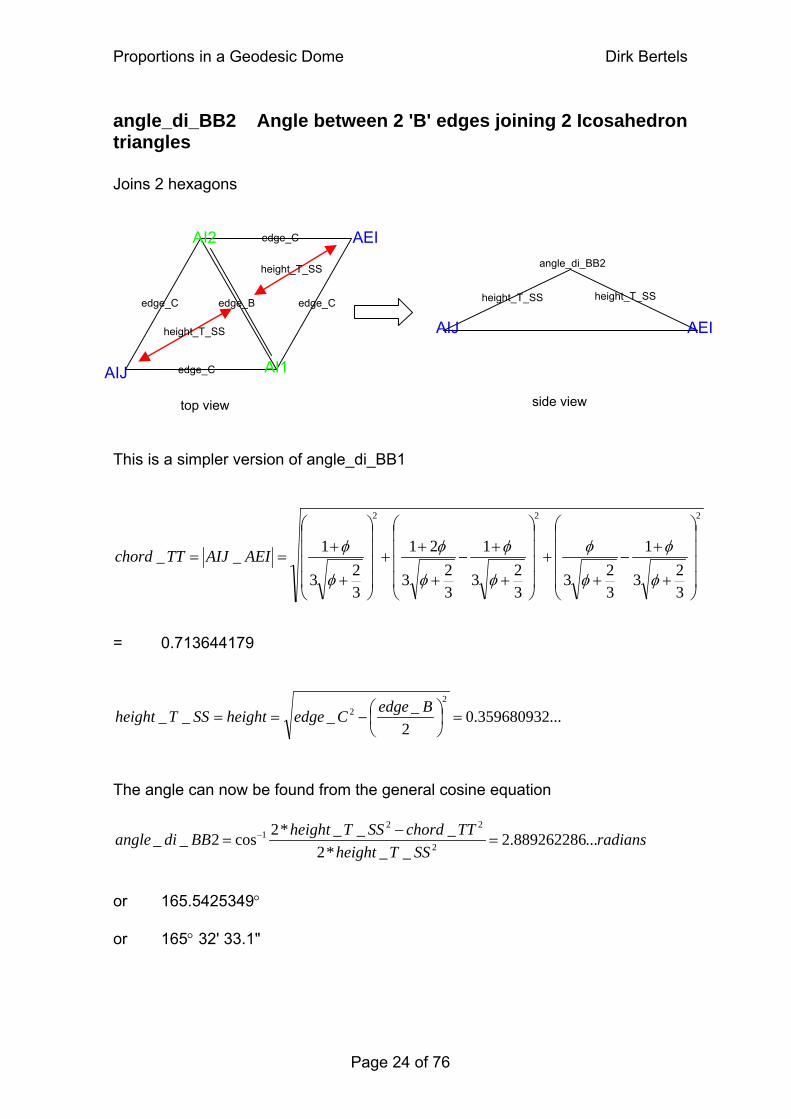
angle_di_BB2 Angle between 2 'B' edges joining 2 Icosahedron triangles Joins 2 hexagons
height_T_SS height_T_SS
AIJ AEI
angle_di_BB2
side view
AEI
AIJ
AI2
AI1
edge_C
edge_C
edge_C
edge_C
edge_B
height_T_SS
height_T_SS
top view
This is a simpler version of angle_di_BB1 222
323
1
323
3232323
__⎟⎟
⎜⎜
+−
++
⎟⎟
⎜⎜
+==
φφφAEIAIJTThord
1
3
21
3
1
⎟⎟⎟⎟
⎠
⎞
⎜⎜⎜⎜
⎝
⎛
+
+−
++⎟
⎟
⎠
⎞
⎜⎜
⎝
⎛++⎟
⎟
⎠
⎞
⎜⎜
⎝
⎛+
φ
φ
φ
φφφφc
= 0.713644179
...359680932.02
____2
2 =⎟⎠⎞
⎜⎝⎛−==
BedgeCedgeheightSST height
The angle can now be found from the general cosine equation
radiansSSTheight
TTchordSSTheightBBdi ...889262286.2__*2
___*2cos2__ 2
221 =
−= −
angle or 165.5425349° or 165° 32' 33.1"
Proportions in a Geodesic Dome Dirk Bertels
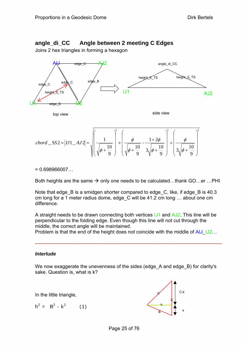
angle_di_CC Angle between 2 meeting C Edges Joins 2 hex triangles in forming a hexagon
height_S_TS height_S_TS
IJ1 AJ2
angle_di_CC
side view
AJ2AIJ
IJ1 IJ2
edge_B
edge_C
edge_B
edge_C edge_C
height_S_TS
top view
222
9103
9103
21
910
910
12_12_⎟⎟⎟⎟
⎠
⎞
⎜⎜⎜⎜
⎝
⎛
++
⎟⎟⎟⎟
⎠
⎞
⎜⎜⎜⎜
⎝
⎛
+
+−
++
⎟⎟⎟⎟
⎠
⎞
⎜⎜⎜⎜
⎝
⎛
+==
φ
φ
φ
φ
φ
φ
φAJIJSS
chord
= 0.698966007… Both heights are the same only one needs to be calculated…thank GO…er …PHI Note that edge_B is a smidgen shorter compared to edge_C, like, if edge_B is 40.3 cm long for a 1 meter radius dome, edge_C will be 41.2 cm long … about one cm difference. A straight needs to be drawn connecting both vertices IJ1 and AJ2. This line will be perpendicular to the folding edge. Even though this line will not cut through the middle, the correct angle will be maintained. Problem is that the end of the height does not coincide with the middle of AIJ_IJ2… -----------------------------------------------------------------------------------------------------------------
Interlude We now exaggerate the unevenness of the sides (edge_A and edge_B) for clarity's sake. Question is, what is k?
C
C
B
h
C-k
k
In the little triangle, h2 = B2 - k2 (1)
Page 25 of 76
Proportions in a Geodesic Dome Dirk Bertels
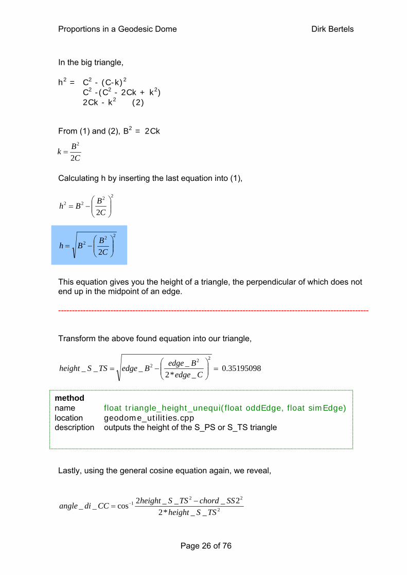
In the big triangle, h2 = C2 - (C-k)2
C2 -(C2 - 2Ck + k2) 2Ck - k2 (2) From (1) and (2), B2 = 2Ck C
Bk2
2
=
Calculating h by inserting the last equation into (1), 22
22
2 ⎟⎟⎠
⎞⎜⎜⎝
⎛−=
CBB
h
22
2
2 ⎟⎟⎠
⎜⎜⎝
−=C
B⎞⎛ B
h
This equation gives you the height of a triangle, the perpendicular of which does not end up in the midpoint of an edge. ----------------------------------------------------------------------------------------------------------------- Transform the above found equation into our triangle,
0.35195098 _*2
____22
2 =⎟⎟⎠
⎞⎜⎜⎝
⎛−=
CedgeBedgeBedgeTSS
height
method name float triangle_height_unequi(float oddEdge, float simEdge) location geodome_utilities.cpp description outputs the height of the S_PS or S_TS triangle Lastly, using the general cosine equation again, we reveal,
2
221
__*22___2cos__
TSSheightSSchordTSSheightCCdi −
= − angle
Page 26 of 76
Proportions in a Geodesic Dome Dirk Bertels
radiansTSSheight
SSchordCCdia
ngle ...904603471.2__*22_1cos__ 2
21 =⎟⎟
⎠
⎞⎜⎜⎝
⎛−= −
or 166.42152° or 166°25°17.4 Divide by 2 for "per triangle" angle
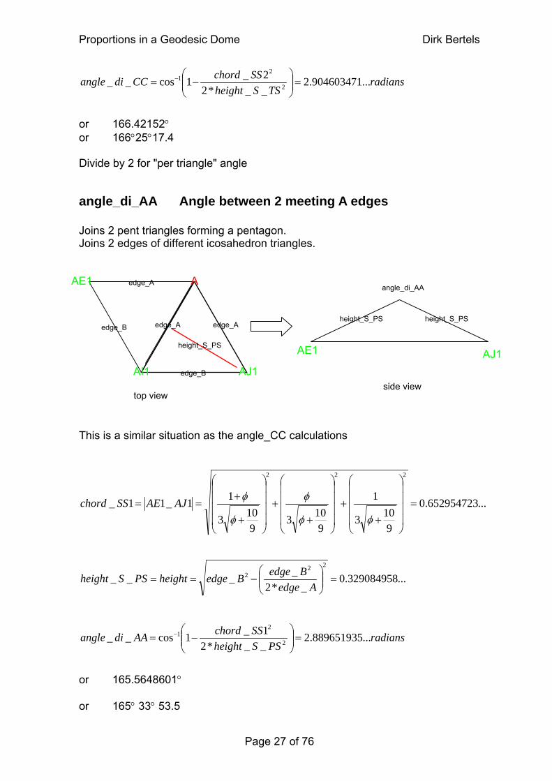
angle_di_AA Angle between 2 meeting A edges Joins 2 pent triangles forming a pentagon. Joins 2 edges of different icosahedron triangles.
AI1 AJ1edge_B
height_S_PS
edge_Aedge_A
edge_A
edge_B
AE1 A
height_S_PS height_S_PS
AE1 AJ1
angle_di_AA
side view top view
This is a similar situation as the angle_CC calculations
...652954723.0
9103
1
9103
9103
11_11_
222
=⎟⎟⎟⎟
⎠
⎞
⎜⎜⎜⎜
⎝
⎛
++
⎟⎟⎟⎟
⎠
⎞
⎜⎜⎜⎜
⎝
⎛
++
⎟⎟⎟⎟
⎠
⎞
⎜⎜⎜⎜
⎝
⎛
+
+==
φφ
φ
φ
φAJAESS chord
...329084958.0_*2
____22
2 =⎟⎟⎠
⎞⎜⎜⎝
⎛−==
AedgeBedgeBedgeheightPSS
height
radiansPSSheight
SSchordAAdi ...889651935.2__*21_1cos__ 2
21 =⎟⎟
⎠
⎞⎜⎜⎝
⎛−= −
angle or 165.5648601° or 165° 33° 53.5
Page 27 of 76
Proportions in a Geodesic Dome Dirk Bertels
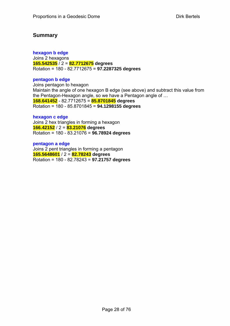
Summary hexagon b edge Joins 2 hexagons 165.542535 / 2 = 82.7712675 degrees Rotation = 180 - 82.7712675 = 97.2287325 degrees pentagon b edge Joins pentagon to hexagon Maintain the angle of one hexagon B edge (see above) and subtract this value from the Pentagon-Hexagon angle, so we have a Pentagon angle of … 168.641452 - 82.7712675 = 85.8701845 degrees Rotation = 180 - 85.8701845 = 94.1298155 degrees hexagon c edge Joins 2 hex triangles in forming a hexagon 166.42152 / 2 = 83.21076 degrees Rotation = 180 - 83.21076 = 96.78924 degrees pentagon a edge Joins 2 pent triangles in forming a pentagon 165.5648601 / 2 = 82.78243 degrees Rotation = 180 - 82.78243 = 97.21757 degrees
Page 28 of 76
Proportions in a Geodesic Dome Dirk Bertels
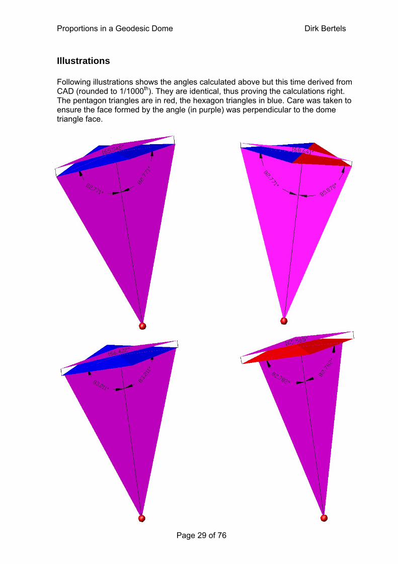
Illustrations Following illustrations shows the angles calculated above but this time derived from CAD (rounded to 1/1000th). They are identical, thus proving the calculations right. The pentagon triangles are in red, the hexagon triangles in blue. Care was taken to ensure the face formed by the angle (in purple) was perpendicular to the dome triangle face.
Page 29 of 76
Proportions in a Geodesic Dome Dirk Bertels
Designing animation objects Having calculated various dimensions and angles, we have come to the point where we can start constructing our animation objects. In fact, we have a lot more information than we actually need for this particular program which after all is mainly concerned with coordinate values because it needs to know where to draw its objects and in what trajectories they need to be moved. The type of geodesic dome we have been describing is fascinating because it is inherently simple in its construction. The whole dome can be built using 2 different triangles: the bcc triangle and the baa triangle. 6 bcc triangles form a hexagon and 5 baa triangles form a pentagon. The whole dome is then built by connecting these hexagons and pentagons. A good way to go about building the dome is by starting with the bcc triangle only. This way a number of hexagons can be built and these hexagons can be interconnected to give you the basic dome shape. The pentagons appear as windows within this dome14. See also the web site http://www.oregonvos.net/~jgarlitz/geodome.htm for a practical discussion on building a real observatory using the 2 triangular blocks mentioned above. Compare the sizes (approximated in inches…) with the ones we derive from our equations. So the following discussion will be about the construction of a bcc triangle block. Many varieties are possible here: we will base ours on the construction of a triangular pyramid15, which is the object created by joining the 3 vertices of a bcc triangle to the center of the dome. The height of the object as well as the thickness of the 'walls' of the object will be variable (the drawings on next pages should make this clear). Changing the height of the triangular pyramid results in a truncated (cut) triangular pyramid. The resulting object is part of the geodesic dome in a real sense, it allows us to create the greatest variety for our building block; from solid to paper thin, and from flat to entire pyramids while maintaining the same dome shape on the outside at all times. The 'cut' triangular pyramid sections will be referred to as triangle blocks from here on.
14 View the animation by double clicking dirkdome.exe. The folder called 'resources' will need to be present in the same directory. 15 A pyramid with a triangular base unlike the ancient pyramid monuments which have a quadrilateral base.
Page 30 of 76
Proportions in a Geodesic Dome Dirk Bertels
Applying an even thickness - background When using a graphics application such as a CAD, it is easy to apply thickness to surfaces. However, we are working at a lower level … as if we were writing the program for the CAD application itself. This means we need to calculate all the necessary coordinates ourselves. This part of the project has proved to be the most challenging, mainly because there are many ways of achieving this goal. Whichever way you choose, it is assumed that we need to construct an object using material with an even thickness. Here are the systems I explored …
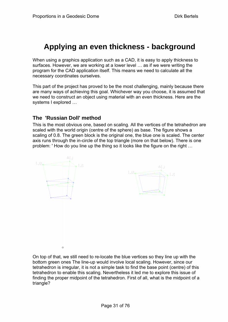
The 'Russian Doll' method This is the most obvious one, based on scaling. All the vertices of the tetrahedron are scaled with the world origin (centre of the sphere) as base. The figure shows a scaling of 0.8. The green block is the original one, the blue one is scaled. The center axis runs through the in-circle of the top triangle (more on that below). There is one problem: ' How do you line up the thing so it looks like the figure on the right … On top of that, we still need to re-locate the blue vertices so they line up with the bottom green ones The line-up would involve local scaling. However, since our tetrahedron is irregular, it is not a simple task to find the base point (centre) of this tetrahedron to enable this scaling. Nevertheless it led me to explore this issue of finding the proper midpoint of the tetrahedron. First of all, what is the midpoint of a triangle?
Page 31 of 76
Proportions in a Geodesic Dome Dirk Bertels
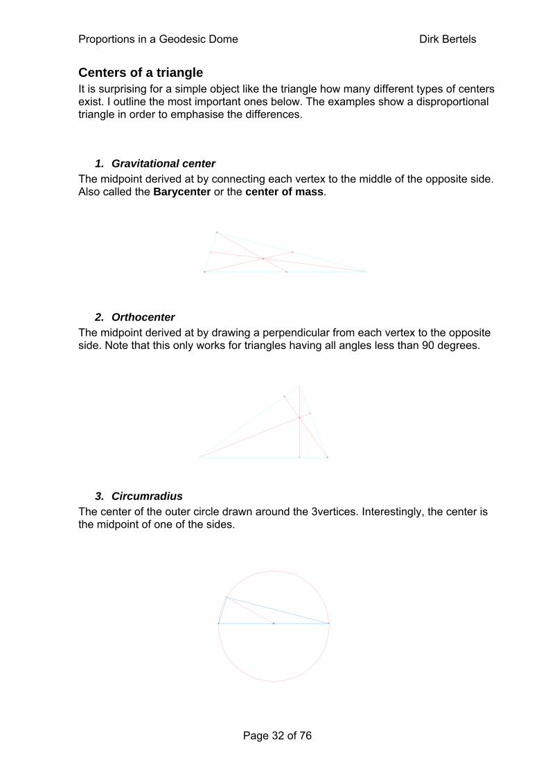
Centers of a triangle It is surprising for a simple object like the triangle how many different types of centers exist. I outline the most important ones below. The examples show a disproportional triangle in order to emphasise the differences.
1. Gravitational center The midpoint derived at by connecting each vertex to the middle of the opposite side. Also called the Barycenter or the center of mass.
2. Orthocenter The midpoint derived at by drawing a perpendicular from each vertex to the opposite side. Note that this only works for triangles having all angles less than 90 degrees.
3. Circumradius The center of the outer circle drawn around the 3vertices. Interestingly, the center is the midpoint of one of the sides.
Page 32 of 76
Proportions in a Geodesic Dome Dirk Bertels
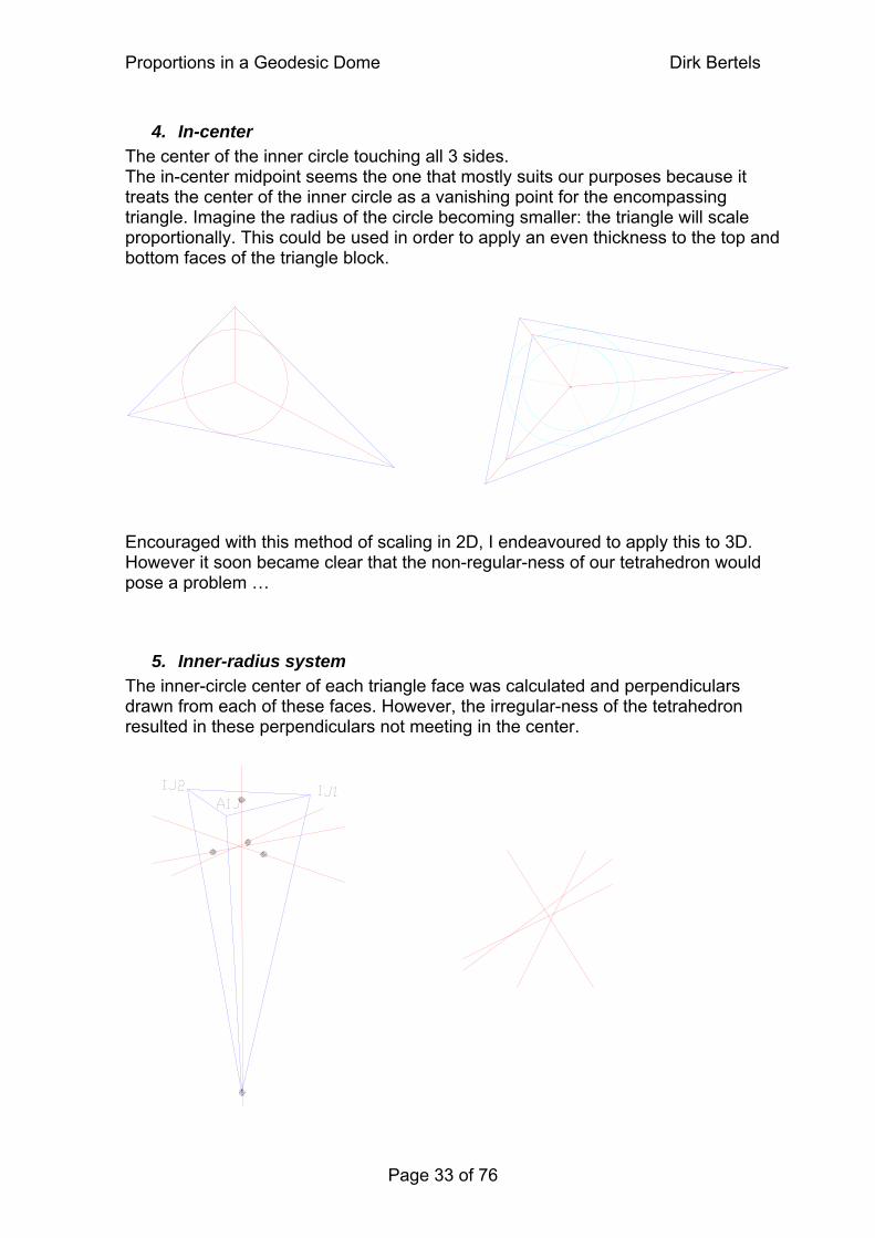
4. In-center The center of the inner circle touching all 3 sides. The in-center midpoint seems the one that mostly suits our purposes because it treats the center of the inner circle as a vanishing point for the encompassing triangle. Imagine the radius of the circle becoming smaller: the triangle will scale proportionally. This could be used in order to apply an even thickness to the top and bottom faces of the triangle block. Encouraged with this method of scaling in 2D, I endeavoured to apply this to 3D. However it soon became clear that the non-regular-ness of our tetrahedron would pose a problem …
5. Inner-radius system The inner-circle center of each triangle face was calculated and perpendiculars drawn from each of these faces. However, the irregular-ness of the tetrahedron resulted in these perpendiculars not meeting in the center.
Page 33 of 76
Proportions in a Geodesic Dome Dirk Bertels
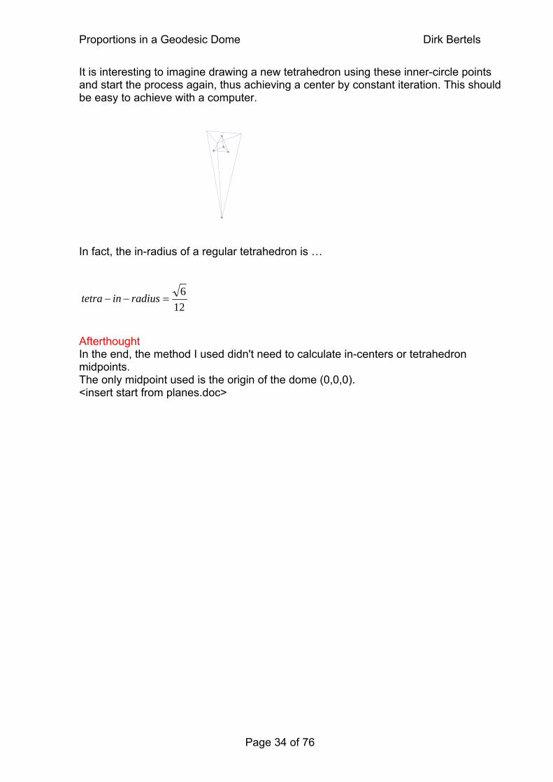
It is interesting to imagine drawing a new tetrahedron using these inner-circle points and start the process again, thus achieving a center by constant iteration. This should be easy to achieve with a computer. In fact, the in-radius of a regular tetrahedron is …
126
=−− radiusin tetra Afterthought In the end, the method I used didn't need to calculate in-centers or tetrahedron midpoints. The only midpoint used is the origin of the dome (0,0,0). <insert start from planes.doc>
Page 34 of 76
Proportions in a Geodesic Dome Dirk Bertels
Applying an even thickness In a previous version of this essay’s chapter, I used a system exploiting a mixture of the inner-circle method plus some standard coordinate - and Euclidean geometry. The system was convoluted and … wrong. The problem was that some calculations were not measuring thickness perpendicular to the surface. Though the results were close enough for the animation which only needed to give a demonstration, I needed accurate measurements for the CAD drawings I needed to design. In the process of solving this problem, I came upon a much more elegant solution using matrices. The starting point for this system is that we can represent each surface with an equation: the Plane Equation.
Translating the plane Applying thickness is equivalent to translating the plane in a direction perpendicular to the plane over a given length (thickness factor). For each plane, the unit normal is calculated. Once that is done, we simply need to multiply this unit normal with the thickness factor and apply this to the plane’s coordinates, effectively translating the plane in the direction of this normal by the required distance (thickness).
Finding the coordinates The intersection of 2 planes constitutes a line, and the intersection of 3 planes constitutes a point. These points being the coordinates we need to enable drawing the triangle block. Following explanation only leads up to one vertex of a hexagon triangle block only, and all explanation has been kept to a minimum.
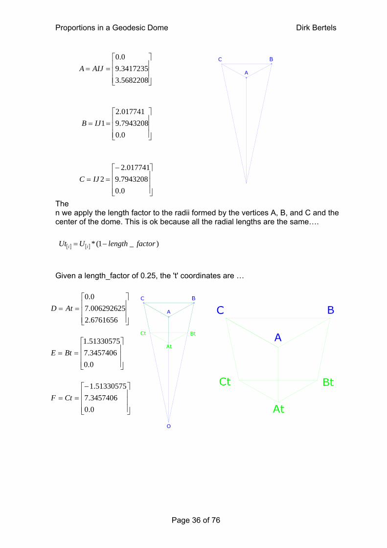
Example triangle block The 5/8 dome contains 2 types of triangle blocks, the Pentagon and the Hexagon triangle block. The size and orientation of these depend on the situation. For clarity we just concentrate on one particular set of coordinates: We assume, for example, the vertices AIJ, IJ1, IJ2 and refer to them as A, B, C respectively in the figures.
Page 35 of 76
Proportions in a Geodesic Dome Dirk Bertels
[ ] [ ] )_1(* factorlengthUUt ii −=
⎥⎥⎥
⎦
⎤
⎢⎢⎢
⎣
⎡==
5682208.33417235.90.0
AIJA
⎥⎥⎥
⎦
⎤
⎢⎢⎢
⎣
⎡==
0.07943208.9017741.2
1IJB
⎥⎥⎥
⎦
⎤
⎢⎢⎢
⎣
⎡−=
0.07943208.9
017741.22IJ=C
Then we apply the length factor to the radii formed by the vertices A, B, and C and the center of the dome. This is ok because all the radial lengths are the same….
Given a length_factor of 0.25, the 't' coordinates are …
⎥⎥⎥
⎦
⎤
⎢⎢⎢
⎣
⎡−==
0.03457406.7
51330575.1CtF
⎥⎥⎥
⎦
⎤
⎢⎢⎢
⎣
⎡==
0.03457406.751330575.1
BtE
⎥⎥⎥
⎦
⎤
⎢⎢⎢
⎣
⎡==
6761656.2006292625.70.0
AtD
Page 36 of 76
Proportions in a Geodesic Dome Dirk Bertels
Plane equations - General
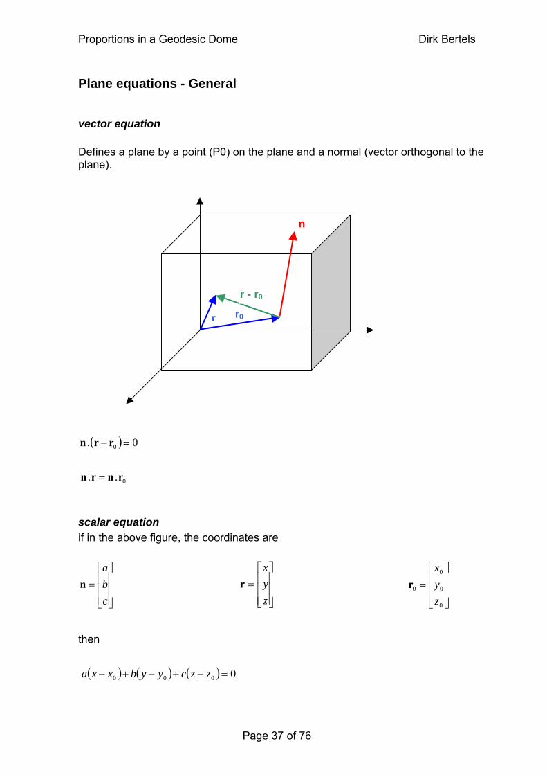
vector equation Defines a plane by a point (P0) on the plane and a normal (vector orthogonal to the plane).
r r0
n
r - r0
=
( ) 0. 0 =− rr n
n 0.. rnr
scalar equation if in the above figure, the coordinates are
⎥⎥⎥
⎦
⎤
⎢⎢⎢
⎣
⎡=
zyx
r⎥⎥⎥
⎦
⎤
⎢⎢⎢
⎣
⎡=
cba
⎥⎥⎥
⎦
⎤
⎢⎢⎢
⎣
⎡=
0
0
0
0
zyx
r n then
( ) ( ) ( ) 0000 =−+−+− zzcyybxxa
Page 37 of 76
Proportions in a Geodesic Dome Dirk Bertels
Page 38 of 76
⎥⎥⎥
⎦
⎤
⎢⎢⎢
⎣
⎡−=
0.04485802.2
50443525.0s
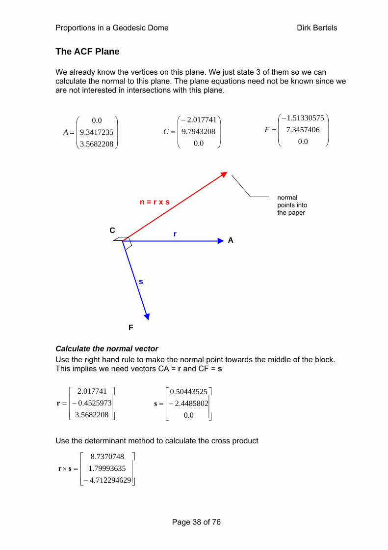
The ACF Plane We already know the vertices on this plane. We just state 3 of them so we can calculate the normal to this plane. The plane equations need not be known since we are not interested in intersections with this plane.
⎟⎟⎟
⎠
⎞
⎜⎜⎜
⎝
⎛−=
0.03457406.751330575.1
F⎟⎟⎟
⎠
⎞
⎜⎜⎜
⎝
⎛−=
0.07943208.9
017741.2C
⎟⎟⎟
⎠
⎞
⎜⎜⎜
⎝
⎛=
5682208.33417235.9
0.0A
C A
F
⎥⎥⎥
⎦
⎤
⎢⎢⎢
⎣
⎡−=
5682208.34525973.0017741.2
r
s
r
n = r x s
normal points into the paper
Calculate the normal vector Use the right hand rule to make the normal point towards the middle of the block. This implies we need vectors CA = r and CF = s Use the determinant method to calculate the cross product
⎥⎥⎥
⎦
⎤
⎢⎢⎢
⎣
⎡
−=×
712294629.479993635.17370748.8
s r
Proportions in a Geodesic Dome Dirk Bertels
Page 39 of 76
926391.7253498128.1
3.0nFFl
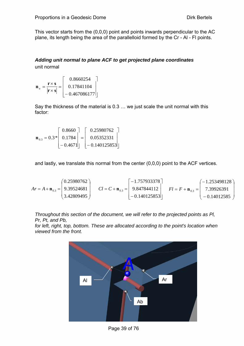
This vector starts from the (0,0,0) point and points inwards perpendicular to the AC plane, its length being the area of the parallelloid formed by the Cr - Al - Fl points.
Adding unit normal to plane ACF to get projected plane coordinates unit normal
⎥⎥⎥
⎦
⎤
⎢⎢⎢
⎣
⎡
−=
××
=467086177.017841104.08660254.0
srsr
n u
Say the thickness of the material is 0.3 … we just scale the unit normal with this factor:
⎥⎥⎥
⎦
⎤
⎢⎢⎢
⎣
⎡
−=
⎥⎥⎥
⎦
⎤
⎢⎢⎢
⎣
⎡
−=
140125853.005352331.025980762.0
4671.01784.08660.0
*3.03.0n
and lastly, we translate this normal from the center (0,0,0) point to the ACF vertices.
⎥⎥⎥
⎦
⎤
⎢⎢⎢
⎣
⎡
−
−=+=
140125853.0847844112.9757933378.1
3.0nCCl⎟⎟⎟
⎠
⎞
⎜⎜⎜
⎝
⎛=+=
42809495.339524681.925980762.0
3.0nAAr ⎟⎟⎟
⎠
⎞
⎜⎜⎜
⎝
⎛
−
−=+=
14012585.039
Throughout this section of the document, we will refer to the projected points as Pl, Pr, Pt, and Pb, for left, right, top, bottom. These are allocated according to the point's location when viewed from the front.
Al Ar
Ab
Proportions in a Geodesic Dome Dirk Bertels
Page 40 of 76
0)140126.0(712295.4)847844.9(799936.1)757933.1(737075.8=
=
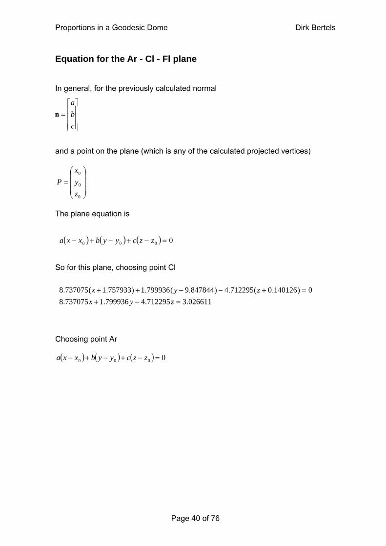
Equation for the Ar - Cl - Fl plane In general, for the previously calculated normal
⎥⎥⎥
⎦
⎤
⎢⎢⎢
⎣
⎡=
cba
n
and a point on the plane (which is any of the calculated projected vertices)
⎟⎟⎟
⎠
⎞
⎜⎜⎜
⎝
⎛=
0
0
0
zyx
P
The plane equation is
( ) ( ) ( ) 0000 =−+−+− zzcyybxxa So for this plane, choosing point Cl
026611.3712295.4799936.1737075.8 −++−−++
zzyx
yx
Choosing point Ar
( ) ( ) ( ) 0000 =−+−+− zzcyybxxa
Proportions in a Geodesic Dome Dirk Bertels
Page 41 of 76
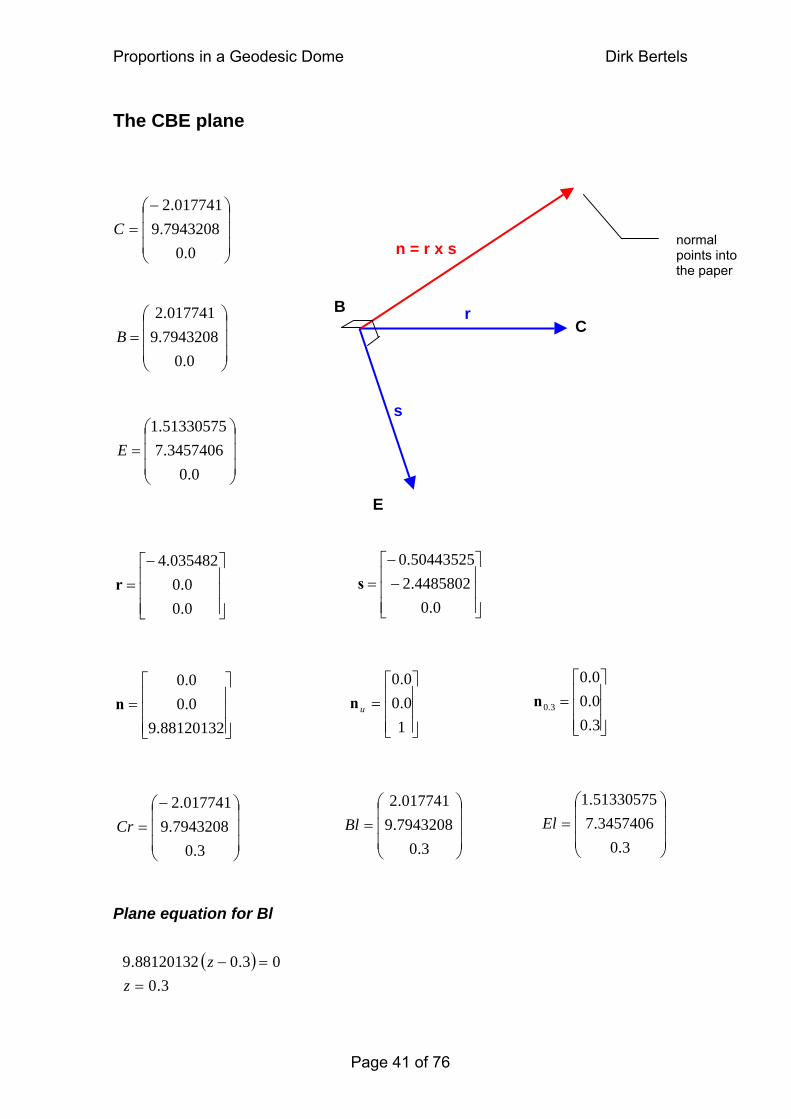
The CBE plane
B C
E
s
r
n = r x s normal points into the paper
⎟⎟⎟
⎠
⎞
⎜⎜⎜
⎝
⎛−=
0.07943208.9
017741.2C
⎟⎟⎟
⎠
⎞
⎜⎜⎜
⎝
⎛=
0.07943208.9017741.2
B
⎟⎟⎟
⎠
⎞
⎜⎜⎜
⎝
⎛=
0.03457406.7
51330575.1
E
⎥⎥⎥
⎦
⎤
⎢⎢⎢
⎣
⎡−−
=0.0
4485802.250443525.0
s⎥⎥⎥
⎦
⎤
⎢⎢⎢
⎣
⎡−=
0.00.0
035482.4 r
⎥⎥⎥
⎦
⎤
⎢⎢⎢
⎣
⎡=
3.00.00.0
3.0n⎥⎥⎥
⎦
⎤
⎢⎢⎢
⎣
⎡=
10.00.0
un⎥⎥⎥
⎦
⎤
⎢⎢⎢
⎣
⎡=
88120132.90.00.0
n
⎟⎟⎟
⎠
⎞
⎜⎜⎜
⎝
⎛=
3.03457406.7
51330575.1El
⎟⎟⎟
⎠
⎞
⎜⎜⎜
⎝
⎛=
3.07943208.9017741.2
Bl⎟⎟⎟
⎠
⎞
⎜⎜⎜
⎝
⎛−=
3.07943208.9
017741.2Cr
Plane equation for Bl ( )
3.003.088120132.9
==−
zz
Proportions in a Geodesic Dome Dirk Bertels
Page 42 of 76
The BAD plane
A B
D
s
r
⎟⎟⎟
⎠
⎞
⎜⎜⎜
⎝
⎛=
0.07943208.9017741.2
B
⎟⎟⎟
⎠
⎞
⎜⎜⎜
⎝
⎛=
5682208.33417235.9
0.0A
Plane equation for Al
n = r x s normal points into the paper
⎟⎟⎟
⎠
⎞
⎜⎜⎜
⎝
⎛=
6761656.2006292625.7
0.0D
⎥⎥⎥
⎦
⎤
⎢⎢⎢
⎣
⎡
−−=
8920552.0335430875.2
0.0s
⎥⎥⎥
⎦
⎤
⎢⎢⎢
⎣
⎡
−=
5682208.34525973.0017741.2
r
⎥⎥⎥
⎦
⎤
⎢⎢⎢
⎣
⎡
−
−=
7122946.479993635.1
7370748.8n
⎥⎥⎥
⎦
⎤
⎢⎢⎢
⎣
⎡
−
−=
467086177.017841104.0
8660254.0
un⎥⎥⎥
⎦
⎤
⎢⎢⎢
⎣
⎡
−
−=
14012585.005352331.0
2598076.0
3.0n
⎟⎟⎟
⎠
⎞
⎜⎜⎜
⎝
⎛
−=
140125853.084784411.975793337.1
Br⎟⎟⎟
⎠
⎞
⎜⎜⎜
⎝
⎛−=
5360397.20598159.725980762.0
Dl⎟⎟⎟
⎠
⎞
⎜⎜⎜
⎝
⎛−=
4280949.339524681.925980762.0
Al
( ) ( ) (026612.3712295.4799936.1737075.8
04280949.37122946.439524681.979993635.125980762.07370748.8=−+−
) =−−−++−zyx
zyx
Proportions in a Geodesic Dome Dirk Bertels
Page 43 of 76
The BCA plane
C B
A
s
r
⎟⎟⎟
⎠
⎞
⎜⎜⎜
⎝
⎛=
0.07943208.9017741.2
B
⎟⎟⎟
⎠
⎞
⎜⎜⎜
⎝
⎛=
5682208.33417235.9
0.0A
⎟⎟⎟
⎠
⎞
⎜⎜⎜
⎝
⎛−=
0.07943208.9
017741.2C
⎟⎟⎟
⎠
⎞
⎜⎜⎜
⎝
⎛
−=
0377498896.0496705367.9
017741.2Bb
⎟⎟⎟
⎠
⎞
⎜⎜⎜
⎝
⎛
−
−=
0377498896.0496705367.9
017741.2Cb
⎥⎥⎥
⎦
⎤
⎢⎢⎢
⎣
⎡=
5304709.3044108067.9
0.0Ab
The plane equation for point Ab
n = r x s normal points into the paper
⎥⎥⎥
⎦
⎤
⎢⎢⎢
⎣
⎡=
0.00.0
035482.4r
⎥⎥⎥
⎦
⎤
⎢⎢⎢
⎣
⎡−=
5682208.34525973.0017741.2
s
⎥⎥⎥
⎦
⎤
⎢⎢⎢
⎣
⎡
−−=
0377498896.029761543.0
0.0
3.0n⎥⎥⎥
⎦
⎤
⎢⎢⎢
⎣
⎡
−−=
125832965.099205144.0
0.0
un⎥⎥⎥
⎦
⎤
⎢⎢⎢
⎣
⎡
−−=
8264482.13994908.14
0.0n
678773.136826448.1399491.140)530471.3(826448.1)044108.9(399491.14
−=−−=−−−−
zyzy
Proportions in a Geodesic Dome Dirk Bertels
Page 44 of 76
39154896293039080577.7
0.0Dt
The EDF plane
⎟⎟⎟
⎠
⎞
⎜⎜⎜
⎝
⎛−=
0.03457406.751330575.1
F
⎟⎟⎟
⎠
⎞
⎜⎜⎜
⎝
⎛=
6761656.2006292625.7
0.0D
⎟⎟⎟
⎠
⎞
⎜⎜⎜
⎝
⎛=
0.03457406.7
51330575.1E
⎟⎟⎟
⎠
⎞
⎜⎜⎜
⎝
⎛=
0377498896.064335603.751330575.1
Et⎟⎟⎟
⎠
⎞
⎜⎜⎜
⎝
⎛=
71. ⎟⎟⎟
⎠
⎞
⎜⎜⎜
⎝
⎛ −=
0377498896.064335603.751330575.1
Ft
( ) ( )027377.1099714.8
0713915.2303908.7099714.8=+ 947778.61
027377.1 =−+−zy
zy
D E
F
The plane equation for point Dt
s
r
n = r x s normal points into the paper
⎥⎥⎥
⎦
⎤
⎢⎢⎢
⎣
⎡
−
−=
6761656.2339447975.0
51330575.1s
⎥⎥⎥
⎦
⎤
⎢⎢⎢
⎣
⎡=
0377498896.029761543.0
0.0
3.0n
⎥⎥⎥
⎦
⎤
⎢⎢⎢
⎣
⎡
−=
6761656.2339447975.051330575.1
r
⎥⎥⎥
⎦
⎤
⎢⎢⎢
⎣
⎡=
125832965.099205144.0
0.0
un⎥⎥⎥
⎦
⎤
⎢⎢⎢
⎣
⎡=
02737714.109971358.8
0.0n
Proportions in a Geodesic Dome Dirk Bertels
Page 45 of 76
Plane intersections Deriving the points from these plane equation is a very easy procedure if you know about matrices and how to solve equations using the Reduced Row Echelon form. We can determine each of the coordinates by intersecting 3 planes; the 3 planes can only intersect in one point.
Point 1: Intersection of planes Ar - Cl - Fl, Br - Al - Dl, and Bb - Cb - Ab The plane equations are
026611.3712295.4799936.1737075.8
−+ zyx = 8 026612.3712295.4799936.1737075. −+− zyx =
678773.136826448.1399491.14 −=−− zy
The derived matrix is Put this in the calculator and we get The values in the last column are the coordinates of the intersection of the 3 planes. The procedure used to put the former matrix in Reduced Row Echelon form is very simple (though time consuming if done by hand).
⎥⎥⎥
⎦
⎤
−−−−−−
678773.136826448.1399491.140.0026612.3712295.4799936.1737075.8026612.3712295.4799936.1737075.8
⎢⎣⎢⎢⎡
⎥⎥⎥
⎦
⎤
⎢⎢⎢
⎣
⎡
845450.2100130997.9010
0001

Proportions in a Geodesic Dome Dirk Bertels
Illustrations I implemented the technique described above to create a library application for AutoCAD 2005 / 6 . Following are 2 example drawings:
Page 46 of 76
Proportions in a Geodesic Dome Dirk Bertels
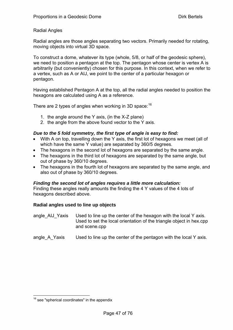
Radial Angles Radial angles are those angles separating two vectors. Primarily needed for rotating, moving objects into virtual 3D space. To construct a dome, whatever its type (whole, 5/8, or half of the geodesic sphere), we need to position a pentagon at the top. The pentagon whose center is vertex A is arbitrarily (but conveniently) chosen for this purpose. In this context, when we refer to a vertex, such as A or AIJ, we point to the center of a particular hexagon or pentagon. Having established Pentagon A at the top, all the radial angles needed to position the hexagons are calculated using A as a reference. There are 2 types of angles when working in 3D space:16
1. the angle around the Y axis, (in the X-Z plane) 2. the angle from the above found vector to the Y axis.
Due to the 5 fold symmetry, the first type of angle is easy to find: • With A on top, travelling down the Y axis, the first lot of hexagons we meet (all of
which have the same Y value) are separated by 360/5 degrees. • The hexagons in the second lot of hexagons are separated by the same angle. • The hexagons in the third lot of hexagons are separated by the same angle, but
out of phase by 360/10 degrees. • The hexagons in the fourth lot of hexagons are separated by the same angle, and
also out of phase by 360/10 degrees. Finding the second lot of angles requires a little more calculation: Finding these angles really amounts the finding the 4 Y values of the 4 lots of hexagons described above. Radial angles used to line up objects angle_AIJ_Yaxis Used to line up the center of the hexagon with the local Y axis. Used to set the local orientation of the triangle object in hex.cpp and scene.cpp angle_A_Yaxis Used to line up the center of the pentagon with the local Y axis.
16 see "spherical coordinates" in the appendix
Page 47 of 76

Proportions in a Geodesic Dome Dirk Bertels
Radial angles used to construct the dome (see hexdome.cpp of the program) angle_A_AIJ angle from the top pentagon to the first lot of hexagons
angle_A_DJI angle from the top pentagon to the second lot of hexagons angle_A_DGJ angle from the top pentagon to the third lot of hexagons angle_A_CGD angle from the top pentagon to the fourth lot of hexagons
Calculating the radial angle between 2 vertices - general equation The cosine of the radial angle is [ ] [ ] [ ] [ ] [ ] [ ]
2_*1_2*12*12*1
vlengthvlengthvvvvvv
angle zzyyxx +=
+ cos_ So the radial angle between 2 vertices is [ ] [ ] [ ] [ ] [ ] [ ]
2_*1_2*12*12*1
cos2_1_ 1
vlengthvlengthvvvvvv
vvangle zzyyxx += − +
method name float vector_separation_3d(float v1[], float v2[]) location geodome_utilities.cpp description outputs the angle in radians between 2 vectors starting at the origin
Applying the above found method to calculate one angle…
angle_A_Yaxis Angle between Y axis and Pentagon A (vertex A). Used to line up the center of the pentagon with the Y axis. coordinates for the Y axis are (0, 1, 0) [ ] [ ] [ ] [ ] [ ] [ ]
⎟⎟⎠
⎞⎜⎜⎝
⎛
+=
++= −−
21cos
_*_***
cos__ 11
φYaxislengthAlengthYaxisAYaxisAYaxisA
YaxisA zzyyxx angle = 1.017222… radians or 58.2825256° or 58°16°57.09
Page 48 of 76
Proportions in a Geodesic Dome Dirk Bertels
Applying the vector_separation_3d method as above, to the other vertices reveals…
angle_AIJ_Yaxis = 0.364864 radians Used to line up the center of the hexagon with the Y axis
angle_A_AIJ = 0.652358 radians angle from the top pentagon to the first lot of hexagons.
angle_A_DJI = 1.38209 radians angle from the top pentagon to the second lot of hexagons
angle_A_DGJ = 1.75951 radians angle from the top pentagon to the third lot of hexagons
angle_A_CGD = 2.48923 radians angle from the top pentagon to the fourth lot of hexagons
Page 49 of 76
Proportions in a Geodesic Dome Dirk Bertels
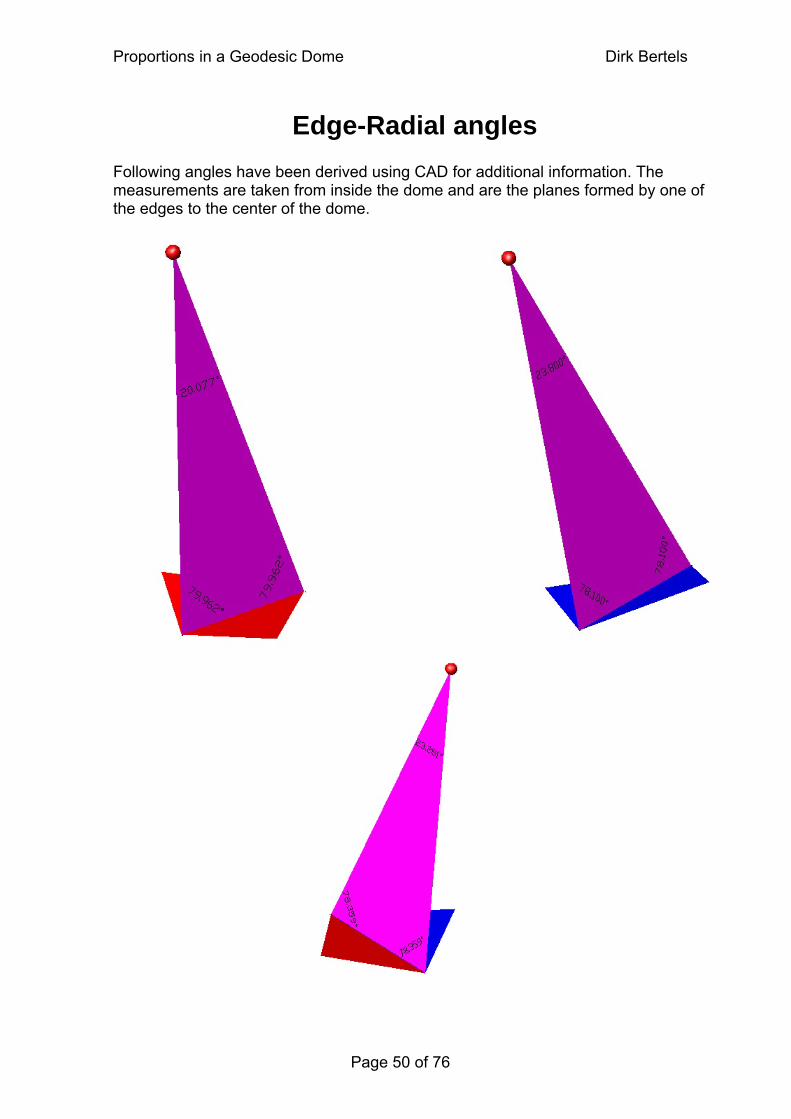
Edge-Radial angles Following angles have been derived using CAD for additional information. The measurements are taken from inside the dome and are the planes formed by one of the edges to the center of the dome.
Page 50 of 76
Proportions in a Geodesic Dome Dirk Bertels
Page 51 of 76
ord_PT chord_TT chord_SS
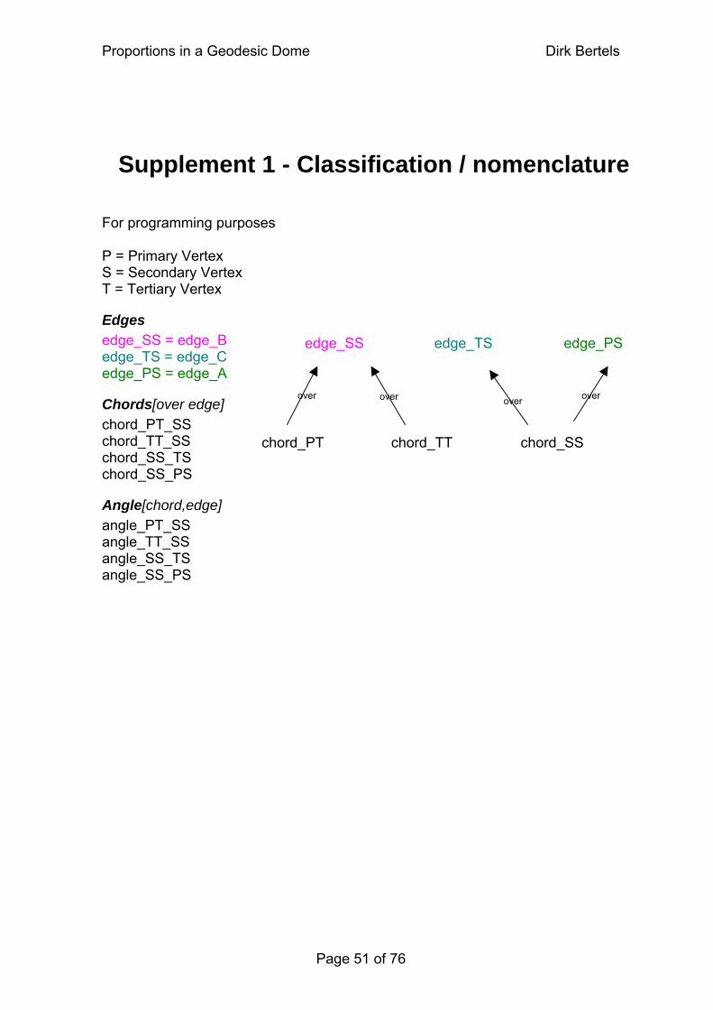
Supplement 1 - Classification / nomenclature For programming purposes P = Primary Vertex S = Secondary Vertex T = Tertiary Vertex
Edges edge_SS = edge_B edge_PS edge_SS edge_TS edge_TS = edge_C edge_PS = edge_A
over over over over Chords[over edge] chord_PT_SS
chchord_TT_SS chord_SS_TS chord_SS_PS
Angle[chord,edge] angle_PT_SS angle_TT_SS angle_SS_TS angle_SS_PS
Proportions in a Geodesic Dome Dirk Bertels
Supplement 2 - Equation Cells
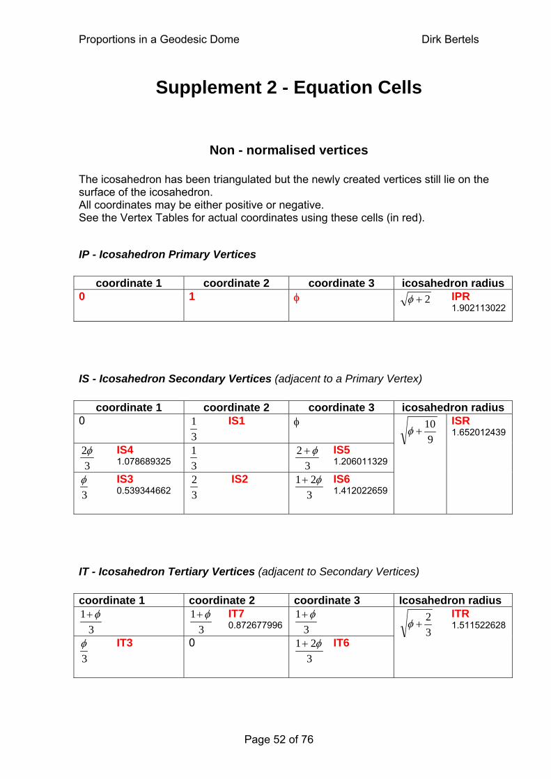
Non - normalised vertices The icosahedron has been triangulated but the newly created vertices still lie on the surface of the icosahedron. All coordinates may be either positive or negative. See the Vertex Tables for actual coordinates using these cells (in red).
IP - Icosahedron Primary Vertices
coordinate 1 coordinate 2 coordinate 3 icosahedron radius 0 1 φ
2+φ
IPR 1.902113022
IS - Icosahedron Secondary Vertices (adjacent to a Primary Vertex)
coordinate 1 coordinate 2 coordinate 3 icosahedron radius 0
31 IS1 φ
32φ IS4
1.078689325 31
32 φ+ IS5
1.206011329
3φ IS3
0.539344662 32 IS2
321 φ+
IS6 1.412022659
910
+φ
ISR 1.652012439
IT - Icosahedron Tertiary Vertices (adjacent to Secondary Vertices) coordinate 1 coordinate 2 coordinate 3 Icosahedron radius
31 φ+
31 φ+ IT7
0.872677996 31 φ+
3φ IT3 0
321 φ+
IT6 32
+φ ITR 1.511522628
Page 52 of 76
Proportions in a Geodesic Dome Dirk Bertels
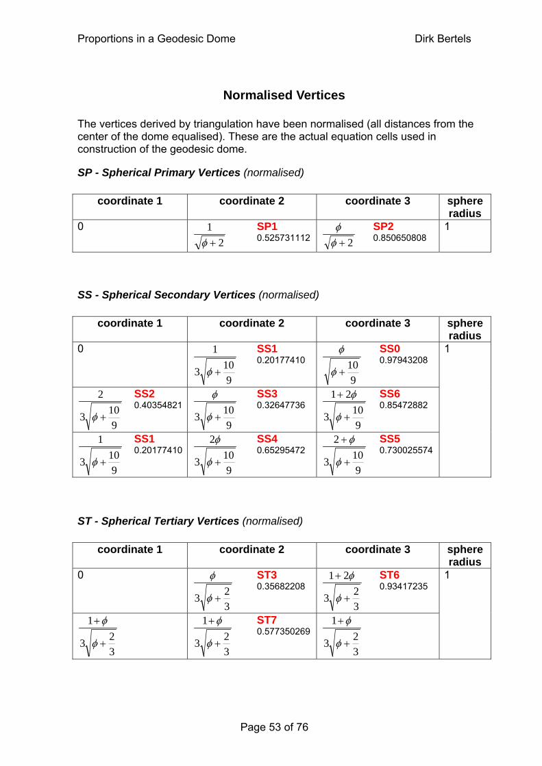
Normalised Vertices The vertices derived by triangulation have been normalised (all distances from the center of the dome equalised). These are the actual equation cells used in construction of the geodesic dome.
SP - Spherical Primary Vertices (normalised)
coordinate 1 coordinate 2 coordinate 3 sphere radius
0 2
1+φ
SP1 0.525731112 2+φ
φ SP2 0.850650808
1
SS - Spherical Secondary Vertices (normalised)
coordinate 1 coordinate 2 coordinate 3 sphere radius
0
9103
1
+φ SS1
0.20177410
910
+φ
φ SS0 0.97943208
9103
2
+φ SS2
0.40354821
9103 +φ
φ SS3 0.32647736
9103
21
+
+
φ
φ SS6 0.85472882
9103
1
+φ SS1
0.20177410
9103
2
+φ
φ SS4 0.65295472
9103
2
+
+
φ
φ SS5 0.730025574
1
ST - Spherical Tertiary Vertices (normalised)
coordinate 1 coordinate 2 coordinate 3 sphere radius
0
323 +φ
φ ST3 0.35682208
323
21
+
+
φ
φ ST6 0.93417235
323
1
+
+
φ
φ
323
1
+
+
φ
φ ST7 0.577350269
323
1
+
+
φ
φ
1
Page 53 of 76
Proportions in a Geodesic Dome Dirk Bertels
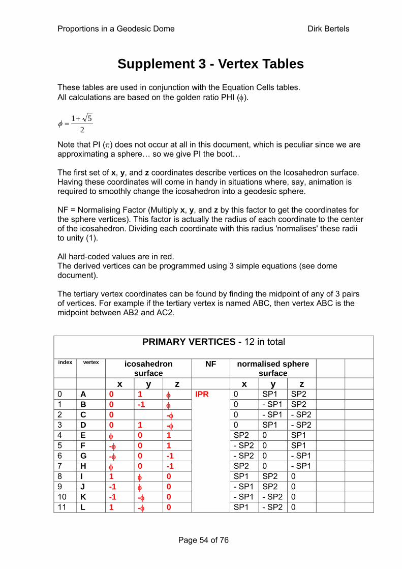
Supplement 3 - Vertex Tables These tables are used in conjunction with the Equation Cells tables. All calculations are based on the golden ratio PHI (φ).
251+
= φ Note that PI (π) does not occur at all in this document, which is peculiar since we are approximating a sphere… so we give PI the boot… The first set of x, y, and z coordinates describe vertices on the Icosahedron surface. Having these coordinates will come in handy in situations where, say, animation is required to smoothly change the icosahedron into a geodesic sphere. NF = Normalising Factor (Multiply x, y, and z by this factor to get the coordinates for the sphere vertices). This factor is actually the radius of each coordinate to the center of the icosahedron. Dividing each coordinate with this radius 'normalises' these radii to unity (1). All hard-coded values are in red. The derived vertices can be programmed using 3 simple equations (see dome document). The tertiary vertex coordinates can be found by finding the midpoint of any of 3 pairs of vertices. For example if the tertiary vertex is named ABC, then vertex ABC is the midpoint between AB2 and AC2.
PRIMARY VERTICES - 12 in total
index vertex icosahedron surface
NF normalised sphere surface
x y z x y z 0 A 0 1 φ 0 SP1 SP2 1 B 0 -1 φ 0 - SP1 SP2 2 C 0 -φ 0 - SP1 - SP2 3 D 0 1 -φ 0 SP1 - SP2 4 E φ 0 1 SP2 0 SP1 5 F -φ 0 1 - SP2 0 SP1 6 G -φ 0 -1 - SP2 0 - SP1 7 H φ 0 -1 SP2 0 - SP1 8 I 1 φ 0 SP1 SP2 0 9 J -1 φ 0 - SP1 SP2 0 10 K -1 -φ 0 - SP1 - SP2 0 11 L 1 -φ 0
IPR
SP1 - SP2 0
Page 54 of 76
Proportions in a Geodesic Dome Dirk Bertels
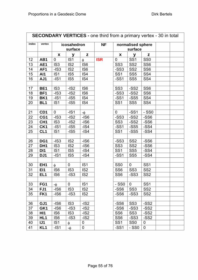
SECONDARY VERTICES - one third from a primary vertex - 30 in total index vertex icosahedron
surface NF normalised sphere
surface
x y z x y z 12 AB1 0 IS1 φ 0 SS1 SS0 13 AE1 IS3 IS2 IS6 SS3 SS2 SS6 14 AF1 -IS3 IS2 IS6 -SS3 SS2 SS6 15 AI1 IS1 IS5 IS4 SS1 SS5 SS4 16 AJ1 -IS1 IS5 IS4 -SS1 SS5 SS4 17 BE1 IS3 -IS2 IS6 SS3 -SS2 SS6 18 BF1 -IS3 -IS2 IS6 -SS3 -SS2 SS6 19 BK1 -IS1 -IS5 IS4 -SS1 -SS5 SS4 20 BL1 IS1 -IS5 IS4 SS1 SS5 SS4 21 CD1 0 -IS1 -φ 0 -SS1 - SS0 22 CG1 -IS3 -IS2 -IS6 -SS3 -SS2 -SS6 23 CH1 IS3 -IS2 -IS6 SS3 -SS2 -SS6 24 CK1 -IS1 -IS5 -IS4 -SS1 -SS5 -SS4 25 CL1 IS1 -IS5 -IS4 SS1 -SS5 -SS4 26 DG1 -IS3 IS2 -IS6 -SS3 SS2 -SS6 27 DH1 IS3 IS2 -IS6 SS3 SS2 -SS6 28 DI1 IS1 IS5 -IS4 SS1 SS5 -SS4 29 DJ1 -IS1 IS5 -IS4 -SS1 SS5 -SS4 30 EH1 φ 0 IS1 SS0 0 SS1 31 EI1 IS6 IS3 IS2 SS6 SS3 SS2 32 EL1 IS6 -IS3 IS2 SS6 -SS3 SS2 33 FG1 -φ 0 IS1 - SS0 0 SS1 34 FJ1 -IS6 IS3 IS2 -SS6 SS3 SS2 35 FK1 -IS6 -IS3 IS2 -SS6 -SS3 SS2 36 GJ1 -IS6 IS3 -IS2 -SS6 SS3 -SS2 37 GK1 -IS6 -IS3 -IS2 -SS6 -SS3 -SS2 38 HI1 IS6 IS3 -IS2 SS6 SS3 -SS2 39 HL1 IS6 -IS3 -IS2 SS6 -SS3 -SS2 40 IJ1 IS1 φ 0 SS1 SS0 0 41 KL1 -IS1 -φ 0
ISR
-SS1 - SS0 0
Page 55 of 76
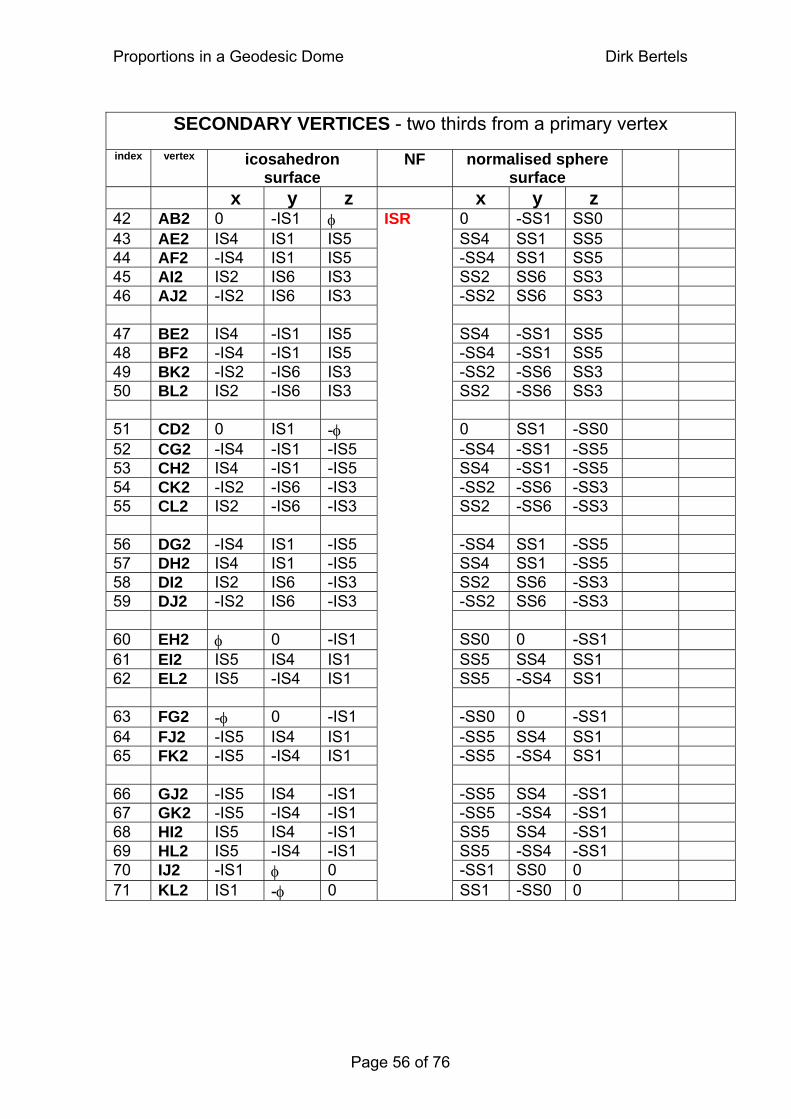
Proportions in a Geodesic Dome Dirk Bertels
SECONDARY VERTICES - two thirds from a primary vertex
index vertex icosahedron surface
NF normalised sphere surface
x y z x y z 42 AB2 0 -IS1 φ 0 -SS1 SS0 43 AE2 IS4 IS1 IS5 SS4 SS1 SS5 44 AF2 -IS4 IS1 IS5 -SS4 SS1 SS5 45 AI2 IS2 IS6 IS3 SS2 SS6 SS3 46 AJ2 -IS2 IS6 IS3 -SS2 SS6 SS3 47 BE2 IS4 -IS1 IS5 SS4 -SS1 SS5 48 BF2 -IS4 -IS1 IS5 -SS4 -SS1 SS5 49 BK2 -IS2 -IS6 IS3 -SS2 -SS6 SS3 50 BL2 IS2 -IS6 IS3 SS2 -SS6 SS3 51 CD2 0 IS1 -φ 0 SS1 -SS0 52 CG2 -IS4 -IS1 -IS5 -SS4 -SS1 -SS5 53 CH2 IS4 -IS1 -IS5 SS4 -SS1 -SS5 54 CK2 -IS2 -IS6 -IS3 -SS2 -SS6 -SS3 55 CL2 IS2 -IS6 -IS3 SS2 -SS6 -SS3 56 DG2 -IS4 IS1 -IS5 -SS4 SS1 -SS5 57 DH2 IS4 IS1 -IS5 SS4 SS1 -SS5 58 DI2 IS2 IS6 -IS3 SS2 SS6 -SS3 59 DJ2 -IS2 IS6 -IS3 -SS2 SS6 -SS3 60 EH2 φ 0 -IS1 SS0 0 -SS1 61 EI2 IS5 IS4 IS1 SS5 SS4 SS1 62 EL2 IS5 -IS4 IS1 SS5 -SS4 SS1 63 FG2 -φ 0 -IS1 -SS0 0 -SS1 64 FJ2 -IS5 IS4 IS1 -SS5 SS4 SS1 65 FK2 -IS5 -IS4 IS1 -SS5 -SS4 SS1 66 GJ2 -IS5 IS4 -IS1 -SS5 SS4 -SS1 67 GK2 -IS5 -IS4 -IS1 -SS5 -SS4 -SS1 68 HI2 IS5 IS4 -IS1 SS5 SS4 -SS1 69 HL2 IS5 -IS4 -IS1 SS5 -SS4 -SS1 70 IJ2 -IS1 φ 0 -SS1 SS0 0 71 KL2 IS1 -φ 0
ISR
SS1 -SS0 0
Page 56 of 76
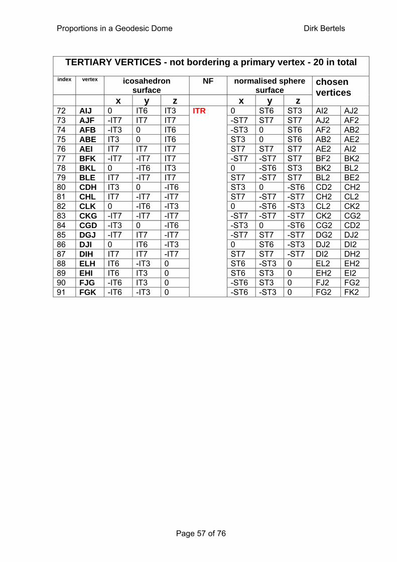
Proportions in a Geodesic Dome Dirk Bertels
TERTIARY VERTICES - not bordering a primary vertex - 20 in total
index vertex icosahedron surface
NF normalised sphere surface
x y z x y z
chosen vertices
72 AIJ 0 IT6 IT3 0 ST6 ST3 AI2 AJ2 73 AJF -IT7 IT7 IT7 -ST7 ST7 ST7 AJ2 AF2 74 AFB -IT3 0 IT6 -ST3 0 ST6 AF2 AB2 75 ABE IT3 0 IT6 ST3 0 ST6 AB2 AE2 76 AEI IT7 IT7 IT7 ST7 ST7 ST7 AE2 AI2 77 BFK -IT7 -IT7 IT7 -ST7 -ST7 ST7 BF2 BK2 78 BKL 0 -IT6 IT3 0 -ST6 ST3 BK2 BL2 79 BLE IT7 -IT7 IT7 ST7 -ST7 ST7 BL2 BE2 80 CDH IT3 0 -IT6 ST3 0 -ST6 CD2 CH2 81 CHL IT7 -IT7 -IT7 ST7 -ST7 -ST7 CH2 CL2 82 CLK 0 -IT6 -IT3 0 -ST6 -ST3 CL2 CK2 83 CKG -IT7 -IT7 -IT7 -ST7 -ST7 -ST7 CK2 CG2 84 CGD -IT3 0 -IT6 -ST3 0 -ST6 CG2 CD2 85 DGJ -IT7 IT7 -IT7 -ST7 ST7 -ST7 DG2 DJ2 86 DJI 0 IT6 -IT3 0 ST6 -ST3 DJ2 DI2 87 DIH IT7 IT7 -IT7 ST7 ST7 -ST7 DI2 DH2 88 ELH IT6 -IT3 0 ST6 -ST3 0 EL2 EH2 89 EHI IT6 IT3 0 ST6 ST3 0 EH2 EI2 90 FJG -IT6 IT3 0 -ST6 ST3 0 FJ2 FG2 91 FGK -IT6 -IT3 0
ITR
-ST6 -ST3 0 FG2 FK2
Page 57 of 76
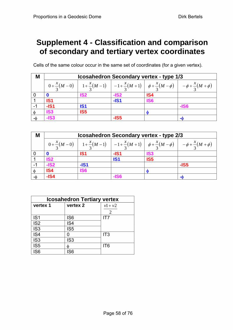
Proportions in a Geodesic Dome Dirk Bertels
Supplement 4 - Classification and comparison of secondary and tertiary vertex coordinates
Cells of the same colour occur in the same set of coordinates (for a given vertex).
Icosahedron Secondary vertex - type 1/3 M ( )0
30 −+ Mx ( )1
31 −+ Mx ( )1
31 ++− Mx ( )φφ −+ Mx
3 ( )φφ ++− Mx
3
0 0 IS2 -IS2 IS4 1 IS1 -IS1 IS6 -1 -IS1 IS1 -IS6 φ IS3 IS5 φ -φ -IS3 -IS5 -φ
Icosahedron Secondary vertex - type 2/3 M ( )0
30 −+ Mx ( )1
31 −+ Mx ( )1
31 ++− Mx ( )φφ −+ Mx
3 ( )φφ ++− Mx
3
0 0 IS1 -IS1 IS3 1 IS2 IS1 IS5 -1 -IS2 -IS1 -IS5 φ IS4 IS6 φ -φ -IS4 -IS6 -φ
Icosahedron Tertiary vertex vertex 1 vertex 2
221 vv +
IS1 IS6 IS2 IS4 IS3 IS5
IT7
IS4 0 IS3 IS3
IT3
IS5 φ IS6 IS6
IT6
Page 58 of 76
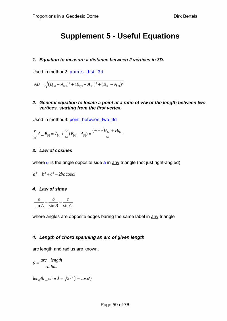
Proportions in a Geodesic Dome Dirk Bertels
Supplement 5 - Useful Equations
1. Equation to measure a distance between 2 vertices in 3D.
Used in method2: points_dist_3d
2][][
2][][
2][][ )()()( zzyyxx ABABABAB −+−+−=
2. General equation to locate a point at a ratio of v/w of the length between two vertices, starting from the first vertex.
Used in method3: point_between_two_3d
[ ] [ ] [ ] [ ]( )
wvBAvw
ABwvABA
wv ii
iiii][][)(_
+−=−+=
3. Law of cosines
where α is the angle opposite side a in any triangle (not just right-angled)
αcos2222 bccba −+=
4. Law of sines
Cc
Bb
Aa
sinsinsin==
where angles are opposite edges baring the same label in any triangle
4. Length of chord spanning an arc of given length
arc length and radius are known.
radiuslengtharc _
=θ
( )θcos12_ 2 −= rchordlength
Page 59 of 76
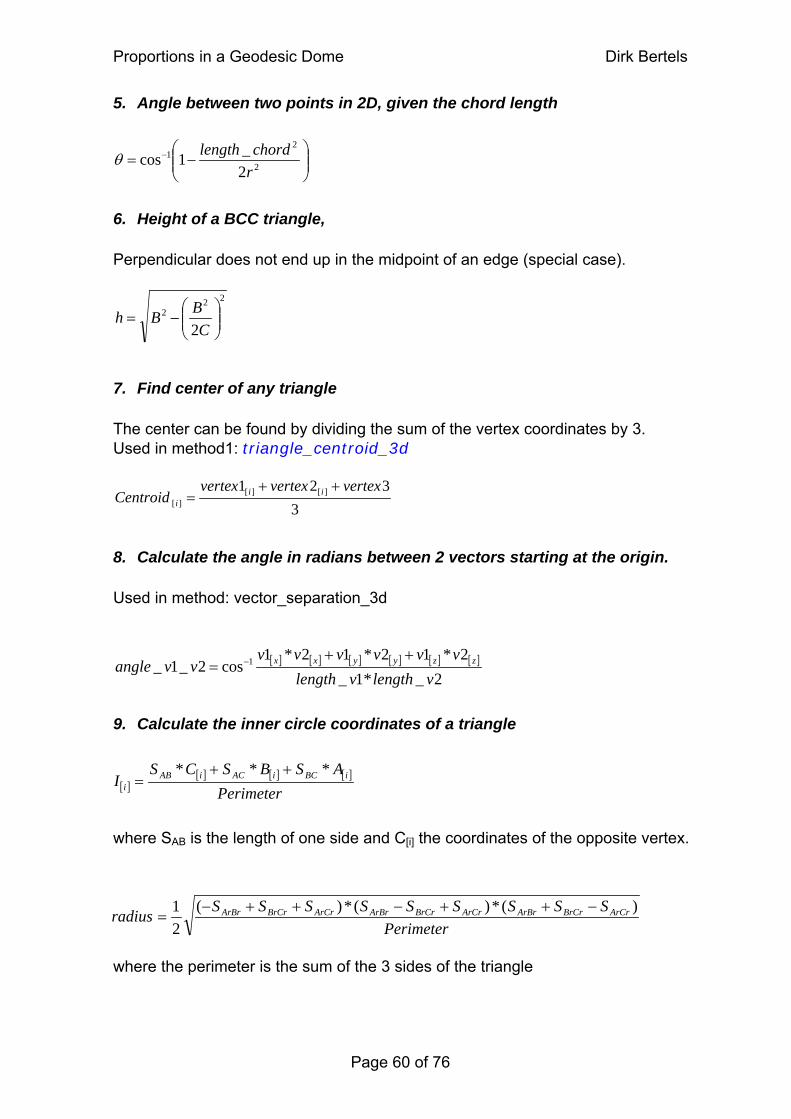
Proportions in a Geodesic Dome Dirk Bertels
5. Angle between two points in 2D, given the chord length
⎟⎟⎠
⎞⎜⎜⎝
⎛−= −
2
21
2_1cosrchordlengthθ
6. Height of a BCC triangle,
Perpendicular does not end up in the midpoint of an edge (special case).
222
2 ⎟⎟⎠
⎞⎜⎜⎝
⎛−=
CBBh
7. Find center of any triangle
The center can be found by dividing the sum of the vertex coordinates by 3. Used in method1: triangle_centroid_3d
3321 ][][
][
vertexvertexvertexCentroid ii
i
++=
8. Calculate the angle in radians between 2 vectors starting at the origin.
Used in method: vector_separation_3d
[ ] [ ] [ ] [ ] [ ] [ ]
2_*1_2*12*12*1
cos2_1_ 1
vlengthvlengthvvvvvv
vvangle zzyyxx ++= −
9. Calculate the inner circle coordinates of a triangle
[ ][ ] [ ] [ ]
PerimeterASBSCS
I iBCiACiABi
*** ++=
where SAB is the length of one side and C[i] the coordinates of the opposite vertex. Perimeter
SSSSSSSSSradius ArCrBrCrArBrArCrBrCrArBrArCrBrCrArBr )(*)(*)(21 −++−++−
=
where the perimeter is the sum of the 3 sides of the triangle
Page 60 of 76
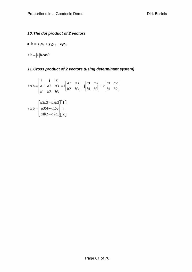
Proportions in a Geodesic Dome Dirk Bertels
Page 61 of 76
10. The dot product of 2 vectors
⎥⎦
⎤⎢⎣
⎡+⎥
⎦
⎤⎢⎣
⎡−⎥
⎦
⎤⎢⎣
⎡=
⎥⎥⎥
⎦
⎤
⎢⎢⎢
⎣
⎡=
2121
3131
3232
321321
bbaa
bbaa
bbaa
bbbaaa kjikji
bxa
⎥⎥⎥
⎦
⎤
⎢⎢⎢
⎣
⎡
⎥⎥⎥
⎦
⎤
⎢⎢⎢
⎣
⎡
−−−
=kji
bxa122131132332
babababababa
212121 zzyyxxba +⋅ = +
cosθbaa.b =
11. Cross product of 2 vectors (using determinant system)
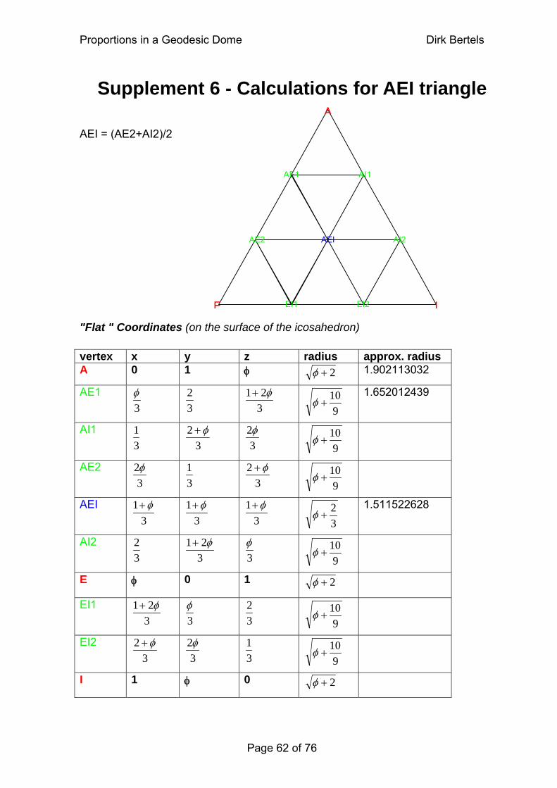
Proportions in a Geodesic Dome Dirk Bertels
Supplement 6 - Calculations for AEI triangle
AE1
AI2
AI1
E
AEI
I
AE2
A AEI = (AE2+AI2)/2
EI1 EI2
"Flat " Coordinates (on the surface of the icosahedron) vertex x y z radius approx. radius A 0 1 φ 2+φ 1.902113032
AE1 3φ
32
321 φ+
910
+φ 1.652012439
AI1 31
32 φ+
32φ
910
+φ
AE2 3
2φ 31
32 φ+
910
+φ
AEI 3
1 φ+ 3
1 φ+ 3
1 φ+ 32
+φ 1.511522628
AI2 32
321 φ+
3φ
910
+φ
E φ 0 1 2+φ
EI1 321 φ+
3φ
32
910
+φ
EI2 3
2 φ+ 3
2φ 31
910
+φ
I 1 φ 0 2+φ
Page 62 of 76
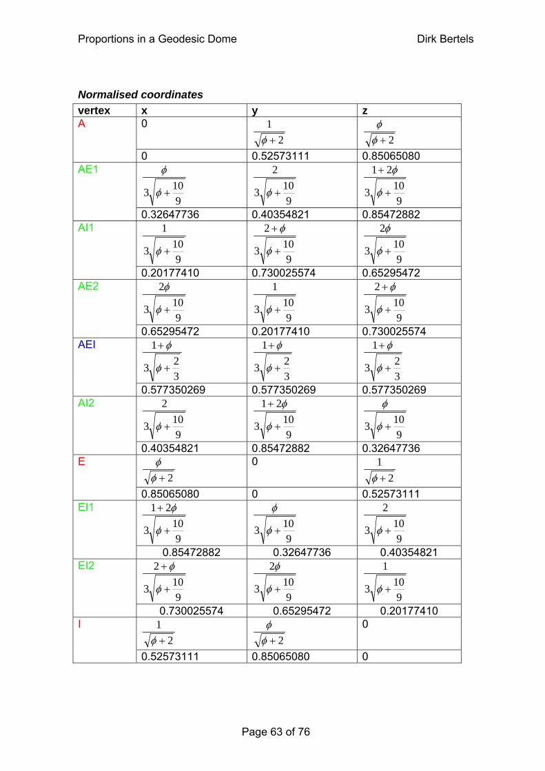
Proportions in a Geodesic Dome Dirk Bertels
Normalised coordinates vertex x y z
0 2
1+φ
2+φ
φ A
0 0.52573111 0.85065080
9103 +φ
φ
9103
2
+φ
9103
21
+
+
φ
φ AE1
0.32647736 0.40354821 0.85472882
9103
1
+φ
9103
2
+
+
φ
φ
9103
2
+φ
φ AI1
0.20177410 0.730025574 0.65295472
9103
2
+φ
φ
9103
1
+φ
9103
2
+
+
φ
φ AE2
0.65295472 0.20177410 0.730025574
323
1
+
+
φ
φ
323
1
+
+
φ
φ
323
1
+
+
φ
φ AEI
0.577350269 0.577350269 0.577350269
9103
2
+φ
9103
21
+
+
φ
φ
9103 +φ
φ AI2
0.40354821 0.85472882 0.32647736
2+φφ 0
21+φ
E
0.85065080 0 0.52573111
9103
21
+
+
φ
φ
9103 +φ
φ
9103
2
+φ EI1
0.85472882 0.32647736 0.40354821
9103
2
+
+
φ
φ
9103
2
+φ
φ
9103
1
+φ EI2
0.730025574 0.65295472 0.20177410
21+φ
2+φ
φ 0 I
0.52573111 0.85065080 0
Page 63 of 76
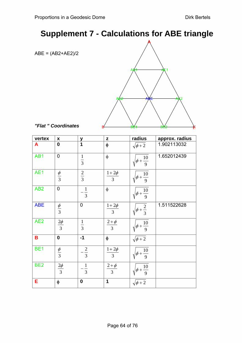
Proportions in a Geodesic Dome Dirk Bertels
AB1
AE2
AE1
B
ABE
E
AB2
ASupplement 7 - Calculations for ABE triangle
ABE = (AB2+AE2)/2
"Flat " Coordinates BE1 BE2 vertex x y z radius approx. radius
1.902113032 A 0 1 φ 2+φ
AB1 0 1.652012439 31 φ
910
+φ
AE1 3φ
32
321 φ+
910
+φ
AB2 0 31
− φ 9
10+φ
ABE 0 1.511522628 321 φ+
3φ
32
+φ
AE2 3
2φ31
32 φ+
910
+φ
B 0 -1 φ 2+φ
BE1 32
−321 φ+
3φ
910
+φ
BE2 3
2φ31
−3
2 φ+
910
+φ
0 1 E φ 2+φ
Page 64 of 76
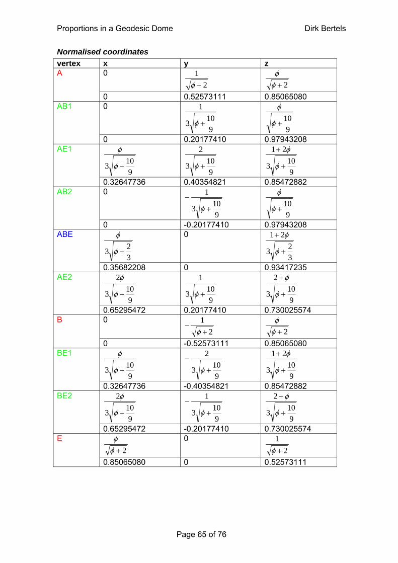
Proportions in a Geodesic Dome Dirk Bertels
Normalised coordinates vertex x y z
0 2
1+φ
2+φ
φ A
0 0.52573111 0.85065080 0
9103
1
+φ
910
+φ
φ AB1
0 0.20177410 0.97943208
9103 +φ
φ
9103
2
+φ
9103
21
+
+
φ
φ AE1
0.32647736 0.40354821 0.85472882 0
9103
1
+−
φ
910
+φ
φ AB2
0 -0.20177410 0.97943208
323 +φ
φ 0
323
21
+
+
φ
φ ABE
0.35682208 0 0.93417235
9103
2
+φ
φ
9103
1
+φ
9103
2
+
+
φ
φ AE2
0.65295472 0.20177410 0.730025574 0
21+
−φ
2+φ
φ B
0 -0.52573111 0.85065080
9103 +φ
φ
9103
2
+−
φ
9103
21
+
+
φ
φ BE1
0.32647736 -0.40354821 0.85472882
9103
2
+φ
φ
9103
1
+−
φ
9103
2
+
+
φ
φ BE2
0.65295472 -0.20177410 0.730025574
2+φφ 0
21+φ
E
0.85065080 0 0.52573111
Page 65 of 76
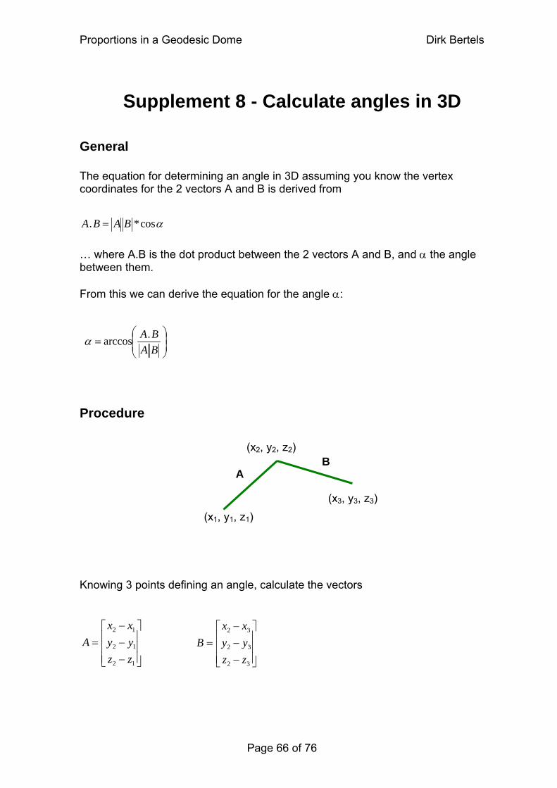
Proportions in a Geodesic Dome Dirk Bertels
Page 66 of 76
Supplement 8 - Calculate angles in 3D
General The equation for determining an angle in 3D assuming you know the vertex coordinates for the 2 vectors A and B is derived from
(x1, y1, z1)(x3, y3, z3)
(x2, y2, z2)
AB
A αcos*. BAB =
… where A.B is the dot product between the 2 vectors A and B, and α the angle between them. From this we can derive the equation for the angle α:
⎟⎟⎠
⎞⎜⎜⎝
⎛=
BABA.arccosα
Procedure Knowing 3 points defining an angle, calculate the vectors
⎥⎥⎥
⎦
⎤⎡ − x
⎢⎢⎢
⎣ −−=
12
12
12
zzyy
x
⎥⎥⎥
⎦
⎤
⎢⎢⎢
⎣
⎡
−−−
=
32
32
32
zzyyxx
BA
Proportions in a Geodesic Dome Dirk Bertels
Note that the point (x2,y2,z2) is the midpoint of the angle and that both subtractions start from this midpoint. Calculate the dot product between 2 vectors in 3D with … A ))(())(())((. 321232123212 zzzzyyyyxxxxB −= − −+ − + − − Calculate the length of the vectors 2
122
122
12 )()()( zzyyxxA −+−+−= 2
322
322
32 )()()( zzyyxxB −+−+−= Finally, use the equation to calculate the angle.
⎟⎟⎠
⎞⎜⎜⎝
⎛=
BABA.arccosα
Page 67 of 76
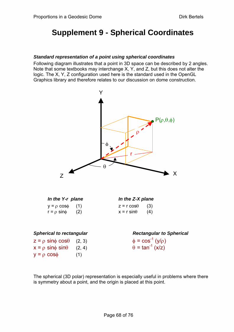
Proportions in a Geodesic Dome Dirk Bertels
Page 68 of 76
Supplement 9 - Spherical Coordinates
Standard representation of a point using spherical coordinates Following diagram illustrates that a point in 3D space can be described by 2 angles. Note that some textbooks may interchange X, Y, and Z, but this does not alter the logic. The X, Y, Z configuration used here is the standard used in the OpenGL Graphics library and therefore relates to our discussion on dome construction. Y
P(ρ,θ,φ)
ρ
φ r
θ X Z
In the Y-r plane In the Z-X plane y = ρ cosφ (1) z = r cosθ (3) r = ρ sinφ (2) x = r sinθ (4)
Spherical to rectangular Rectangular to Spherical z = ρ sinφ cosθ (2, 3) φ = cos-1 (y/ρ) x = ρ sinφ sinθ (2, 4) θ = tan-1 (x/z) y = ρ cosφ (1) The spherical (3D polar) representation is especially useful in problems where there is symmetry about a point, and the origin is placed at this point.
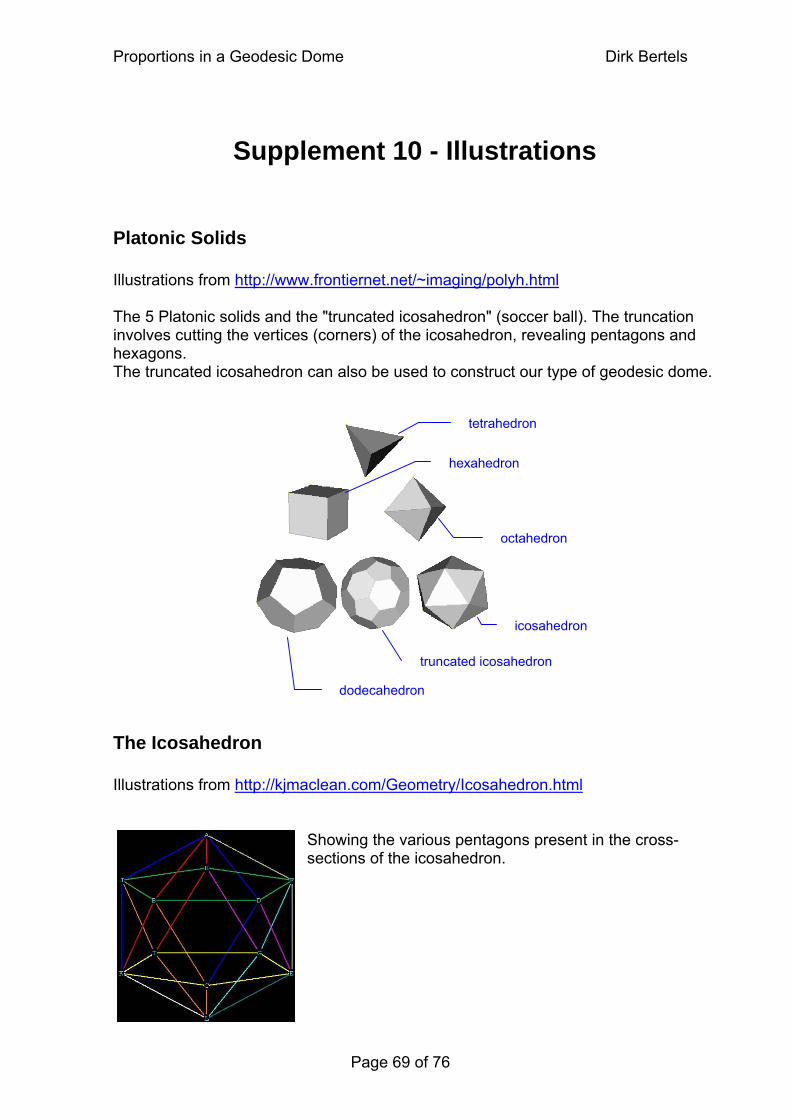
Proportions in a Geodesic Dome Dirk Bertels
Supplement 10 - Illustrations
Platonic Solids Illustrations from http://www.frontiernet.net/~imaging/polyh.html The 5 Platonic solids and the "truncated icosahedron" (soccer ball). The truncation involves cutting the vertices (corners) of the icosahedron, revealing pentagons and hexagons. The truncated icosahedron can also be used to construct our type of geodesic dome.
icosahedron
truncated icosahedron
dodecahedron
hexahedron
octahedron
tetrahedron
The Icosahedron Illustrations from http://kjmaclean.com/Geometry/Icosahedron.html
Showing the various pentagons present in the cross-sections of the icosahedron.
Page 69 of 76
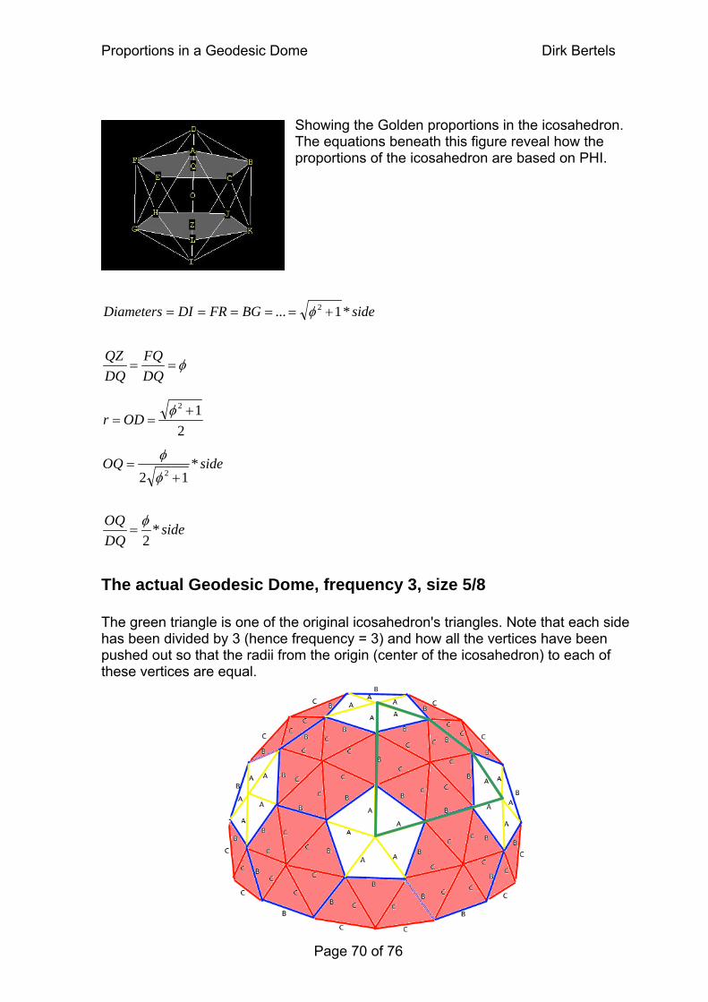
Proportions in a Geodesic Dome Dirk Bertels
Showing the Golden proportions in the icosahedron. The equations beneath this figure reveal how the proportions of the icosahedron are based on PHI.
The actual Geodesic Dome, frequency 3, size 5/8 The green triangle is one of the original icosahedron's triangles. Note that each side has been divided by 3 (hence frequency = 3) and how all the vertices have been pushed out so that the radii from the origin (center of the icosahedron) to each of these vertices are equal.
sideBGFRDI *1... 2 +===== φDiameters
φ==DQFQ
DQQZ
212 +
==φ
ODr
sideOQ *12 2 +
=φφ
sideDQOQ *
2φ
=
Page 70 of 76
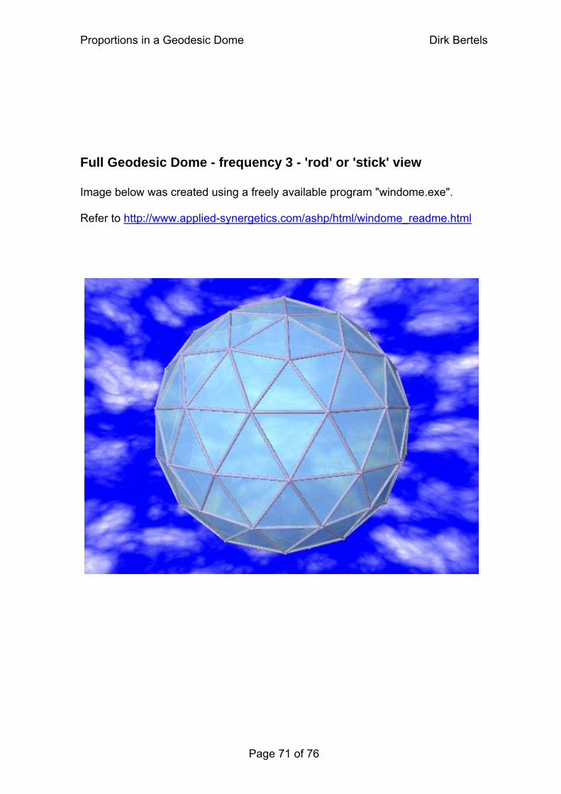
Proportions in a Geodesic Dome Dirk Bertels
Full Geodesic Dome - frequency 3 - 'rod' or 'stick' view Image below was created using a freely available program "windome.exe". Refer to http://www.applied-synergetics.com/ashp/html/windome_readme.html
Page 71 of 76
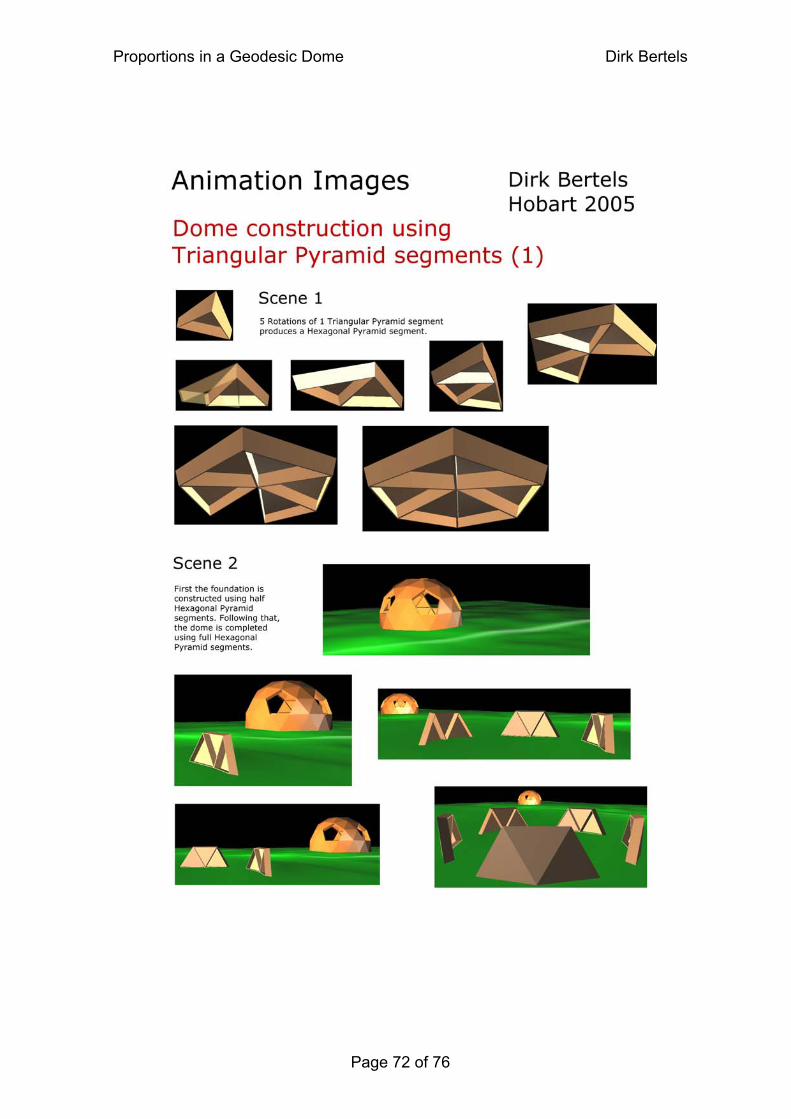
Proportions in a Geodesic Dome Dirk Bertels
Page 72 of 76
Animation Images
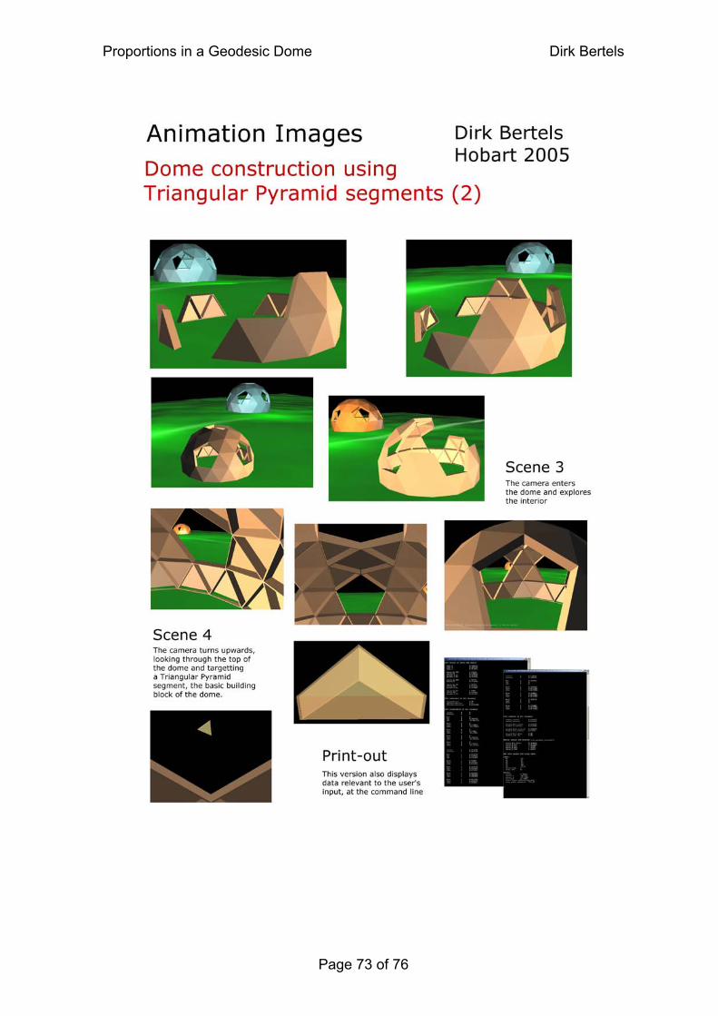
Proportions in a Geodesic Dome Dirk Bertels
Page 73 of 76
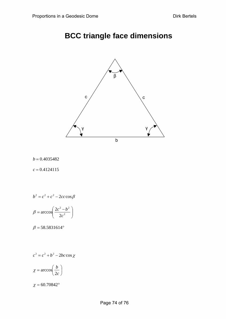
Proportions in a Geodesic Dome Dirk Bertels
BCC triangle face dimensions
γ
c
γ
c
b
β
4035482.0=b
4124115.0=c
βcos2222 ccccb −+=
⎟⎟⎠
⎞⎜⎜⎝
⎛ −= 2
22
22arccos
cbcβ
°= 5831614.58β
χcos2222 bcbcc −+=
⎟⎠⎞
⎜⎝⎛=
cb2
arccosχ
°= 70842.60χ
Page 74 of 76
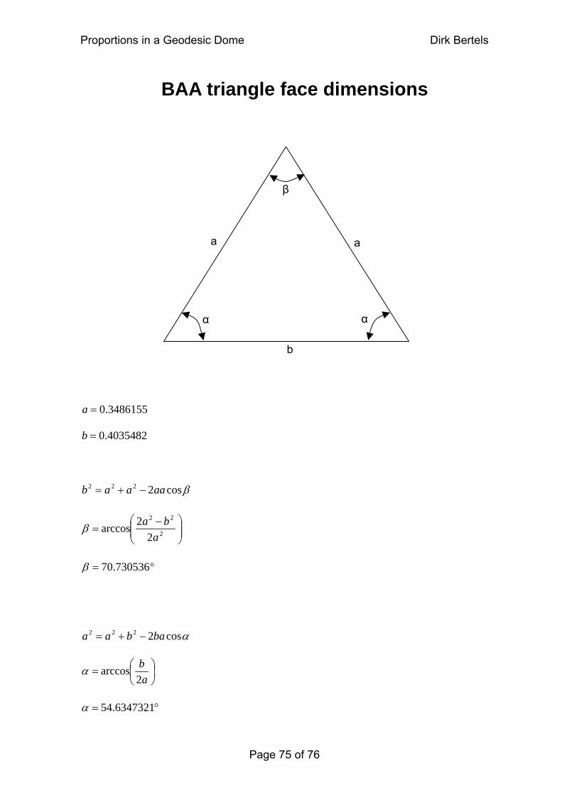
Proportions in a Geodesic Dome Dirk Bertels
BAA triangle face dimensions
α
a
α
a
b
β
3486155.0=a
4035482.0=b
βcos2222 aaaab −+=
⎟⎟⎠
⎞⎜⎜⎝
⎛ −= 2
22
22arccos
abaβ
°= 730536.70β
αcos2222 babaa −+=
⎟⎠⎞
⎜⎝⎛=
ab2
arccosα
°= 6347321.54α
Page 75 of 76
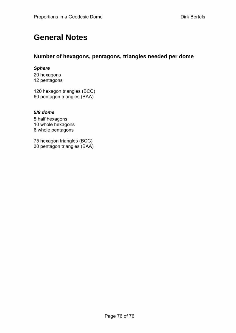
Proportions in a Geodesic Dome Dirk Bertels
General Notes
Number of hexagons, pentagons, triangles needed per dome
Sphere 20 hexagons 12 pentagons 120 hexagon triangles (BCC) 60 pentagon triangles (BAA)
5/8 dome 5 half hexagons 10 whole hexagons 6 whole pentagons 75 hexagon triangles (BCC) 30 pentagon triangles (BAA)
Page 76 of 76
Recommended