ThinkPad T410 and T410iHardware Maintenance Manual


ThinkPad T410 and T410iHardware Maintenance Manual
NoteBefore using this information and the product it supports, be sure to read the general information under “Notices” on page193.
First Edition (January 2010)
© Copyright Lenovo 2010.
LENOVO products, data, computer software, and services have been developed exclusively at private expense andare sold to governmental entities as commercial items as defined by 48 C.F.R. 2.101 with limited and restrictedrights to use, reproduction and disclosure.
LIMITED AND RESTRICTED RIGHTS NOTICE: If products, data, computer software, or services are deliveredpursuant a General Services Administration ″GSA″ contract, use, reproduction, or disclosure is subject to restrictionsset forth in Contract No. GS-35F-05925.
© Lenovo 2010
Contents
About this manual . . . . . . . . . . v
Safety information . . . . . . . . . . 1General safety . . . . . . . . . . . . . . 2Electrical safety . . . . . . . . . . . . . 3Safety inspection guide . . . . . . . . . . . 5Handling devices that are sensitive to electrostaticdischarge . . . . . . . . . . . . . . . 6Grounding requirements . . . . . . . . . . 6Safety notices (multilingual translations) . . . . . 7Laser compliance statement (multilingualtranslations) . . . . . . . . . . . . . . 28
Important service information . . . . . 39Strategy for replacing FRUs . . . . . . . . . 39
Strategy for replacing a hard disk drive . . . . 40Important notice for replacing a system board . . 40How to use error message . . . . . . . . 40
Strategy for replacing FRUs for CTO, CMV, andGAV. . . . . . . . . . . . . . . . . 41
Product definition . . . . . . . . . . . 41FRU identification for CTO, CMV, and GAVproducts . . . . . . . . . . . . . . 41
General checkout . . . . . . . . . . 43What to do first . . . . . . . . . . . . . 44Checkout guide . . . . . . . . . . . . . 45
Diagnostics using PC-Doctor for DOS . . . . 45Lenovo ThinkVantage Toolbox (Lenovo SystemToolbox) . . . . . . . . . . . . . . 48PC-Doctor for Rescue and Recovery . . . . . 48FRU tests . . . . . . . . . . . . . . 49
Power system checkout . . . . . . . . . . 51Checking the AC adapter . . . . . . . . . 51Checking operational charging . . . . . . . 52Checking the battery pack . . . . . . . . 52Checking the backup battery . . . . . . . 53
Related service information. . . . . . 55Restoring the factory contents by using RecoveryDisc Set . . . . . . . . . . . . . . . 55Passwords . . . . . . . . . . . . . . . 56
Power-on password . . . . . . . . . . 57Hard-disk password . . . . . . . . . . 57Supervisor password . . . . . . . . . . 57How to remove the power-on password . . . . 57How to remove the hard-disk password . . . . 58
Power management . . . . . . . . . . . 60Screen blank mode . . . . . . . . . . . 60Sleep (standby) mode . . . . . . . . . . 60Hibernation mode . . . . . . . . . . . 61
Symptom-to-FRU index . . . . . . . . . . 62Numeric error codes . . . . . . . . . . 62Error messages . . . . . . . . . . . . 66
Beep symptoms . . . . . . . . . . . . 67No-beep symptoms. . . . . . . . . . . 67LCD-related symptoms . . . . . . . . . 68Intermittent problems . . . . . . . . . . 69Undetermined problems . . . . . . . . . 69
Status indicators . . . . . . . . . . 71
Fn key combinations . . . . . . . . 75
FRU replacement notices . . . . . . . 79Screw notices . . . . . . . . . . . . . . 79Retaining serial numbers . . . . . . . . . . 80
Restoring the serial number of the system unit 80Retaining the UUID . . . . . . . . . . 80Reading or writing the ECA information . . . 81
Removing and replacing a FRU . . . . 83Before servicing ThinkPad T410 and T410i . . . . 841010 Battery pack . . . . . . . . . . . . 851020 ExpressCard blank bezel . . . . . . . . 871030 Serial Ultrabay Slim device or travel bezel . . 881040 Hard disk drive (HDD) slot cover, HDD rubberrails and HDD or storage converter and solid statedrive (SSD) . . . . . . . . . . . . . . 891050 DIMM slot cover . . . . . . . . . . . 911060 DIMM (in bottom slot) . . . . . . . . . 921070 PCI Express Mini Card for wireless WAN . . 931080 Keyboard . . . . . . . . . . . . . 951090 DIMM (in slot under keyboard) . . . . . 1011100 Backup battery . . . . . . . . . . . 1031110 PCI Express Mini Card for wireless LAN . . 1051120 Keyboard bezel assembly, FPC cable, andBluethooth daughter card (BDC-2.1) . . . . . . 1071130 SmartCard or Contactless SmartCard . . . . 1121140 Modem daughter card (MDC) . . . . . . 1141150 Speaker assembly . . . . . . . . . . 1151160 LCD unit . . . . . . . . . . . . . 1171170 Fan assembly. . . . . . . . . . . . 1231180 CPU. . . . . . . . . . . . . . . 1261190 Base cover assembly, I/O sub card, and I/Osub card cable . . . . . . . . . . . . . 1271200 Magnesium structure frame . . . . . . . 1331210 System board, DC-in connector cable, andExpressCard slot assembly . . . . . . . . . 1352010 LCD bezel assembly . . . . . . . . . 1382020 LED board . . . . . . . . . . . . 1402030 Integrated camera . . . . . . . . . . 1412040 LCD panel and LCD cable . . . . . . . 1422050 Camera cable. . . . . . . . . . . . 1442060 Wireless LAN antenna assembly or wirelessLAN/WAN antenna assembly. . . . . . . . 1462070 Hinges and LCD rear cover assembly . . . 148
© Copyright Lenovo 2010 iii
Locations . . . . . . . . . . . . . 149Front view . . . . . . . . . . . . . . 149Rear view . . . . . . . . . . . . . . 151Bottom view. . . . . . . . . . . . . . 152
Parts list . . . . . . . . . . . . . 153Overall . . . . . . . . . . . . . . . 154LCD FRUs . . . . . . . . . . . . . . 170Keyboard. . . . . . . . . . . . . . . 178Miscellaneous parts . . . . . . . . . . . 179AC adapters. . . . . . . . . . . . . . 181Power cords . . . . . . . . . . . . . . 182
Recovery discs . . . . . . . . . . . . . 183Windows XP Professional (32 bit) DVDs . . . 183Windows Vista Business (32 bit) DVDs . . . . 184Windows 7 Home Basic (32 bit) DVDs . . . . 185Windows 7 Home Premium (32 bit) DVDs . . 186Windows 7 Home Premium (64 bit) DVDs . . 187Windows 7 Professional (32 bit) DVDs . . . . 188Windows 7 Professional (64 bit) DVDs . . . . 190
Common service tools . . . . . . . . . . 191
Notices . . . . . . . . . . . . . . 193Trademarks . . . . . . . . . . . . . . 194
iv ThinkPad T410 Hardware Maintenance Manual
About this manual
This manual contains service and reference information for the followingThinkPad® products.
ThinkPad T410 and T410iMT 2516, 2518, 2519, 2522, 2537, 2538, and 2539
Use this manual along with the advanced diagnostic tests to troubleshootproblems.
Important:This manual is intended only for trained service technicians who are familiarwith ThinkPad products. Use this manual along with the advanced diagnostictests to troubleshoot problems effectively.
Before servicing a ThinkPad product, be sure to read all the information under“Safety information” on page 1 and “Important service information” on page 39.
© Copyright Lenovo 2010 v

vi ThinkPad T410 Hardware Maintenance Manual
Safety information
This chapter presents following safety information that you need to be familiarwith before you service a ThinkPad Notebook.v “General safety” on page 2v “Electrical safety” on page 3v “Safety inspection guide” on page 5v “Handling devices that are sensitive to electrostatic discharge” on page 6v “Grounding requirements” on page 6v “Safety notices (multilingual translations)” on page 7v “Laser compliance statement (multilingual translations)” on page 28
© Copyright Lenovo 2010 1
General safetyFollow these rules to ensure general safety:v Observe good housekeeping in the area of the machines during and after
maintenance.v When lifting any heavy object:
1. Make sure that you can stand safely without slipping.2. Distribute the weight of the object equally between your feet.3. Use a slow lifting force. Never move suddenly or twist when you attempt to
lift.4. Lift by standing or by pushing up with your leg muscles; this action removes
the strain from the muscles in your back. Do not attempt to lift any object thatweighs more than 16 kg (35 lb) or that you think is too heavy for you.
v Do not perform any action that causes hazards to the customer, or that makesthe equipment unsafe.
v Before you start the machine, make sure that other service technicians and thecustomer’s personnel are not in a hazardous position.
v Place removed covers and other parts in a safe place, away from all personnel,while you are servicing the machine.
v Keep your toolcase away from walk areas so that other people will not trip overit.
v Do not wear loose clothing that can be trapped in the moving parts of amachine. Make sure that your sleeves are fastened or rolled up above yourelbows. If your hair is long, fasten it.
v Insert the ends of your necktie or scarf inside clothing or fasten it with anonconductive clip, about 8 centimeters (3 inches) from the end.
v Do not wear jewelry, chains, metal-frame eyeglasses, or metal fasteners for yourclothing.Attention: Metal objects are good electrical conductors.
v Wear safety glasses when you are hammering, drilling, soldering, cutting wire,attaching springs, using solvents, or working in any other conditions that mightbe hazardous to your eyes.
v After service, reinstall all safety shields, guards, labels, and ground wires.Replace any safety device that is worn or defective.
v Reinstall all covers correctly before returning the machine to the customer.v Fan louvers on the machine help to prevent overheating of internal components.
Do not obstruct fan louvers or cover them with labels or stickers.
2 ThinkPad T410 Hardware Maintenance Manual
Electrical safetyObserve the following rules when working on electrical equipment.
v Find the room emergency power-off (EPO) switch, disconnecting switch, orelectrical outlet. If an electrical accident occurs, you can then operate the switchor unplug the power cord quickly.
v Do not work alone under hazardous conditions or near equipment that hashazardous voltages.
v Disconnect all power before:– Performing a mechanical inspection– Working near power supplies– Removing or installing main units
v Before you start to work on the machine, unplug the power cord. If you cannotunplug it, ask the customer to power-off the wall box that supplies power to themachine, and to lock the wall box in the off position.
v If you need to work on a machine that has exposed electrical circuits, observe thefollowing precautions:– Ensure that another person, familiar with the power-off controls, is near you.
Attention: Another person must be there to switch off the power, ifnecessary.
– Use only one hand when working with powered-on electrical equipment;keep the other hand in your pocket or behind your back.Attention: An electrical shock can occur only when there is a completecircuit. By observing the above rule, you may prevent a current from passingthrough your body.
– When using testers, set the controls correctly and use the approved probeleads and accessories for that tester.
– Stand on suitable rubber mats (obtained locally, if necessary) to insulate youfrom grounds such as metal floor strips and machine frames.
Observe the special safety precautions when you work with very high voltages;Instructions for these precautions are in the safety sections of maintenanceinformation. Use extreme care when measuring high voltages.
v Regularly inspect and maintain your electrical hand tools for safe operationalcondition.
v Do not use worn or broken tools and testers.v Never assume that power has been disconnected from a circuit. First, check that it
has been powered off.v Always look carefully for possible hazards in your work area. Examples of these
hazards are moist floors, nongrounded power extension cables, power surges,and missing safety grounds.
Important:Use only approved tools and test equipment. Some hand tools have handlescovered with a soft material that does not insulate you when working with liveelectrical currents.
Many customers have, near their equipment, rubber floor mats that contain smallconductive fibers to decrease electrostatic discharges. Do not use this type of matto protect yourself from electrical shock.
Safety information 3
v Do not touch live electrical circuits with the reflective surface of a plastic dentalmirror. The surface is conductive; such touching can cause personal injury andmachine damage.
v Do not service the following parts with the power on when they are removedfrom their normal operating places in a machine:– Power supply units– Pumps– Blowers and fans– Motor generators– Similar units to listed aboveThis practice ensures correct grounding of the units.
v If an electrical accident occurs:– Use caution; do not become a victim yourself.– Switch off power.– Send another person to get medical aid.
4 ThinkPad T410 Hardware Maintenance Manual
Safety inspection guideThe purpose of this inspection guide is to assist you in identifying potentiallyunsafe conditions. As each machine was designed and built, required safety itemswere installed to protect users and service technicians from injury. This guideaddresses only those items. You should use good judgment to identify potentialsafety hazards due to attachment of non-ThinkPad features or options not coveredby this inspection guide.
If any unsafe conditions are present, you must determine how serious the apparenthazard could be and whether you can continue without first correcting theproblem.
Consider these conditions and the safety hazards they present:v Electrical hazards, especially primary power (primary voltage on the frame can
cause serious or fatal electrical shock)v Explosive hazards, such as a damaged CRT face or a bulging capacitorv Mechanical hazards, such as loose or missing hardware
To determine whether there are any potentially unsafe conditions, use thefollowing checklist at the beginning of every service task. Begin the checks withthe power off, and the power cord disconnected.
Checklist:1. Check exterior covers for damage (loose, broken, or sharp edges).2. Power off the computer. Disconnect the power cord.3. Check the power cord for:
a. A third-wire ground connector in good condition. Use a meter to measurethird-wire ground continuity for 0.1 ohm or less between the externalground pin and the frame ground.
b. The power cord should be the type specified in the parts list.c. Insulation must not be frayed or worn.
4. Check for cracked or bulging batteries.5. Remove the cover.6. Check for any obvious non-ThinkPad alterations. Use good judgment as to the
safety of any non-ThinkPad alterations.7. Check inside the unit for any obvious unsafe conditions, such as metal filings,
contamination, water or other liquids, or signs of fire or smoke damage.8. Check for worn, frayed, or pinched cables.9. Check that the power-supply cover fasteners (screws or rivets) have not been
removed or tampered with.
Safety information 5
Handling devices that are sensitive to electrostatic dischargeAny computer part containing transistors or integrated circuits (ICs) should beconsidered sensitive to electrostatic discharge (ESD.) ESD damage can occur whenthere is a difference in charge between objects. Protect against ESD damage byequalizing the charge so that the machine, the part, the work mat, and the personhandling the part are all at the same charge.
When handling ESD-sensitive parts:v Keep the parts in protective packages until they are inserted into the product.v Avoid contact with other people.v Wear a grounded wrist strap against your skin to eliminate static on your body.v Prevent the part from touching your clothing. Most clothing is insulative and
retains a charge even when you are wearing a wrist strap.v Use a grounded work mat to provide a static-free work surface. The mat is
especially useful when handling ESD-sensitive devices.v Select a grounding system, such as those listed below, to provide protection that
meets the specific service requirement.
– Attach the ESD ground clip to any frame ground, ground braid, or green-wireground.
– When working on a double-insulated or battery-operated system, use an ESDcommon ground or reference point. You can use coax or connector-outsideshells on these systems.
– Use the round ground prong of the ac plug on ac-operated computers.
Grounding requirementsElectrical grounding of the computer is required for operator safety and correctsystem function. Proper grounding of the electrical outlet can be verified by acertified electrician.
Notes:
1. Use product-specific ESD procedures when they exceed the requirementsnoted here.
2. Make sure that the ESD protective devices you use have been certified (ISO9000) as fully effective.
Note:The use of a grounding system to guard against ESD damage is desirable but notnecessary.
6 ThinkPad T410 Hardware Maintenance Manual
Safety notices (multilingual translations)The safety notices in this section are provided in the following languages:v Englishv Arabicv Brazilian Portuguesev Frenchv Germanv Hebrewv Japanesev Koreanv Spanishv Traditional Chinese
Safety information 7
DANGER
Before the computer is powered on after FRU replacement, make sure all screws,springs, and other small parts are in place and are not left loose inside the computer.Verify this by shaking the computer and listening for rattling sounds. Metallic parts ormetal flakes can cause electrical shorts.
DANGER
Some standby batteries contain a small amount of nickel and cadmium. Do notdisassemble a standby battery, recharge it, throw it into fire or water, or short-circuit it.Dispose of the battery as required by local ordinances or regulations. Use only thebattery in the appropriate parts listing. Use of an incorrect battery can result in ignitionor explosion of the battery.
DANGER
The battery pack contains small amounts of nickel. Do not disassemble it, throw it intofire or water, or short-circuit it. Dispose of the battery pack as required by localordinances or regulations. Use only the battery in the appropriate parts listing whenreplacing the battery pack. Use of an incorrect battery can result in ignition or explosionof the battery.
DANGER
The lithium battery can cause a fire, an explosion, or a severe burn. Do not recharge it,remove its polarized connector, disassemble it, heat it above 100°C (212°F), incinerate it,or expose its cell contents to water. Dispose of the battery as required by localordinances or regulations. Use only the battery in the appropriate parts listing. Use of anincorrect battery can result in ignition or explosion of the battery.
DANGER
If the LCD breaks and the fluid from inside the LCD gets into your eyes or on yourhands, immediately wash the affected areas with water for at least 15 minutes. Seekmedical care if any symptoms from the fluid are present after washing.
8 ThinkPad T410 Hardware Maintenance Manual
DANGER
To avoid shock, do not remove the plastic cover that protects the lower part of theinverter card.
DANGER
Though the main batteries have low voltage, a shorted or grounded battery can produceenough current to burn personnel or combustible materials.
DANGER
Unless hot swap is allowed for the FRU being replaced, do as follows before removingit: power off the computer, unplug all power cords from electrical outlets, remove thebattery pack, and disconnect any interconnecting cables.
Safety information 9
10 ThinkPad T410 Hardware Maintenance Manual
Safety information 11
PERIGO
Antes de ligar o computador após a substituição da FRU, certifique-se de que todos osparafusos, molas e outras peças pequenas estejam no lugar e não estejam soltos dentrodo computador. Verifique isso sacudindo o computador e procurando ouvir sons depeças soltas. Peças metálicas ou lascas de metal podem causar curto-circuito.
PERIGO
Algumas baterias reserva contêm uma pequena quantidade de níquel e cádmio. Nãodesmonte uma bateria reserva, recarregue-a, jogue-a no fogo ou na água, ou deixe-aentrar em curto-circuito. Descarte a bateria conforme requerido pelas leis ouregulamentos locais. Use somente a bateria nas partes listadas apropriadas. O uso deuma bateria incorreta pode resultar em combustão ou explosão da bateria.
PERIGO
O pacote da bateria contém uma pequena quantidade de níquel. Não o desmonte,jogue-o no fogo ou na água, ou deixe-o entrar em curto-circuito. Descarte o pacote dabateria conforme requerido pelas leis ou regulamentos locais. Use somente a bateria naspartes listadas apropriadas ao substituir o pacote da bateria. O uso de uma bateriaincorreta pode resultar em combustão ou explosão da bateria.
PERIGO
A bateria de lítio pode causar incêndio, explosão ou graves queimaduras. Não arecarregue, remova seu conector polarizado, desmonte-a, aqueça-a acima de 100°C(212°F), incinere-a, ou exponha o conteúdo de sua célula à água. Descarte a bateriaconforme requerido pelas leis ou regulamentos locais. Use somente a bateria nas parteslistadas apropriadas. O uso de uma bateria incorreta pode resultar em combustão ouexplosão da bateria.
PERIGO
Se o LCD quebrar e o fluido de dentro dele entrar em contato com seus olhos ou comsuas mãos, lave as áreas afetadas imediatamente com água durante pelo menos 15minutos. Procure cuidados médicos se algum sintoma causado pelo fluido surgir após alavagem.
12 ThinkPad T410 Hardware Maintenance Manual
PERIGO
Para evitar choque elétrico, não remova a capa plástica que protege a parte inferior daplaca inversora.
PERIGO
Embora as principais baterias possuam baixa voltagem, uma bateria em curto-circuito ouaterrada pode produzir corrente o bastante para queimar materiais de pessoal ouinflamáveis.
PERIGO
A menos que uma hot swap seja permitida para a FRU que está sendo substituída, façao seguinte antes de removê-la: desligue o computador, desconecte todos os cabos deenergia das tomadas, remova o pacote de baterias e desconecte quaisquer cabos deinterconexão.
Safety information 13
DANGER
Avant de remettre l’ordinateur sous tension après remplacement d’une unité en clientèle,vérifiez que tous les ressorts, vis et autres pièces sont bien en place et bien fixées. Pource faire, secouez l’unité et assurez-vous qu’aucun bruit suspect ne se produit. Des piècesmétalliques ou des copeaux de métal pourraient causer un court-circuit.
DANGER
Certaines batteries de secours contiennent du nickel et du cadmium. Ne les démontezpas, ne les rechargez pas, ne les exposez ni au feu ni à l’eau. Ne les mettez pas encourt-circuit. Pour les mettre au rebut, conformez-vous à la réglementation en vigueur.Lorsque vous remplacez la pile de sauvegarde ou celle de l’horloge temps réel, veillez àn’utiliser que les modèles cités dans la liste de pièces détachées adéquate. Une batterieou une pile inappropriée risque de prendre feu ou d’exploser.
DANGER
La batterie contient du nickel. Ne la démontez pas, ne l’exposez ni au feu ni à l’eau. Nela mettez pas en court-circuit. Pour la mettre au rebut, conformez-vous à laréglementation en vigueur. Lorsque vous remplacez la batterie, veillez à n’utiliser queles modèles cités dans la liste de pièces détachées adéquate. En effet, une batterieinappropriée risque de prendre feu ou d’exploser.
DANGER
La pile de sauvegarde contient du lithium. Elle présente des risques d’incendie,d’explosion ou de brûlures graves. Ne la rechargez pas, ne retirez pas son connecteurpolarisé et ne la démontez pas. Ne l’exposez pas à une temperature supérieure à 100°C,ne la faites pas brûler et n’en exposez pas le contenu à l’eau. Mettez la pile au rebutconformément à la réglementation en vigueur. Une pile inappropriée risque de prendrefeu ou d’exploser.
DANGER
Si le panneau d’affichage à cristaux liquides se brise et que vous recevez dans les yeuxou sur les mains une partie du fluide, rincez-les abondamment pendant au moinsquinze minutes. Consultez un médecin si des symptômes persistent après le lavage.
14 ThinkPad T410 Hardware Maintenance Manual
DANGER
Afin d’éviter tout risque de choc électrique, ne retirez pas le cache en plastiqueprotégeant la partie inférieure de la carte d’alimentation.
DANGER
Bien que le voltage des batteries principales soit peu élevé, le court-circuit ou la mise àla masse d’une batterie peut produire suffisamment de courant pour brûler desmatériaux combustibles ou causer des brûlures corporelles graves.
DANGER
Si le remplacement à chaud n’est pas autorisé pour l’unité remplaçable sur site que vousremplacez, procédez comme suit avant de retirer l’unité : mettez l’ordinateur horstension, débranchez tous les cordons d’alimentation des prises de courant, retirez le blocde batterie et déconnectez tous les câbles d’interconnexion.
Safety information 15
VORSICHT
Bevor nach einem FRU-Austausch der Computer wieder angeschlossen wird,muß sichergestellt werden, daß keine Schrauben, Federn oder andere Kleinteilefehlen oder im Gehäuse vergessen wurden. Der Computer muß geschüttelt undauf Klappergeräusche geprüft werden. Metallteile oder-splitter könnenKurzschlüsse erzeugen.
VORSICHT
Die Bereitschaftsbatterie, die sich unter dem Diskettenlaufwerk befindet, kanngeringe Mengen Nickel und Cadmium enthalten. Sie darf nur durch dieVerkaufsstelle oder den IBM Kundendienst ausgetauscht werden. Sie darf nichtzerlegt, wiederaufgeladen, kurzgeschlossen, oder Feuer oder Wasser ausgesetztwerden. Die Batterie kann schwere Verbrennungen oder Verätzungenverursachen. Bei der Entsorgung die örtlichen Bestimmungen für Sondermüllbeachten. Beim Ersetzen der Bereitschafts-oder Systembatterie nur Batterien desTyps verwenden, der in der Ersatzteilliste aufgeführt ist. Der Einsatz falscherBatterien kann zu Entzündung oder Explosion führen.
VORSICHT
Akkus enthalten geringe Mengen von Nickel. Sie dürfen nicht zerlegt,wiederaufgeladen, kurzgeschlossen, oder Feuer oder Wasser ausgesetzt werden.Bei der Entsorgung die örtlichen Bestimmungen für Sondermüll beachten.Beim Ersetzen der Batterie nur Batterien des Typs verwenden, der in derErsatzteilliste aufgeführt ist. Der Einsatz falscher Batterien kann zuEntzündung oder Explosion führen.
VORSICHT
Die Systembatterie ist eine Lithiumbatterie. Sie kann sich entzünden,explodieren oder schwere Verbrennungen hervorrufen. Batterien dieses Typsdürfen nicht aufgeladen, zerlegt, über 100 C erhitzt oder verbrannt werden.Auch darf ihr Inhalt nicht mit Wasser in Verbindung gebracht oder der zurrichtigen Polung angebrachte Verbindungsstecker entfernt werden. Bei derEntsorgung die örtlichen Bestimmungen für Sondermüll beachten. BeimErsetzen der Batterie nur Batterien des Typs verwenden, der in derErsatzteilliste aufgeführt ist. Der Einsatz falscher Batterien kann zuEntzündung oder Explosion führen.
16 ThinkPad T410 Hardware Maintenance Manual
VORSICHT
Die Leuchtstoffröhre im LCD-Bildschirm enthält Quecksilber. Bei derEntsorgung die örtlichen Bestimmungen für Sondermüll beachten. DerLCD-Bildschirm besteht aus Glas und kann zerbrechen, wenn er unsachgemäßbehandelt wird oder der Computer auf den Boden fällt. Wenn der Bildschirmbeschädigt ist und die darin befindliche Flüssigkeit in Kontakt mit Haut undAugen gerät, sollten die betroffenen Stellen mindestens 15 Minuten mit Wasserabgespült und bei Beschwerden anschließend ein Arzt aufgesucht werden.
VORSICHT
Aus Sicherheitsgründen die Kunststoffabdeckung, die den unteren Teil derSpannungswandlerplatine umgibt, nicht entfernen.
VORSICHT
Obwohl Hauptbatterien eine niedrige Spannung haben, können sie doch beiKurzschluß oder Erdung genug Strom abgeben, um brennbare Materialien zuentzünden oder Verletzungen bei Personen hervorzurufen.
VORSICHT
Wenn ein Austausch der FRU bei laufendem Betrieb nicht erlaubt ist, gehenSie beim Austausch der FRU wie folgt vor: Schalten Sie den Computer aus,ziehen Sie alle Netzkabel von den Netzsteckdosen ab, entfernen Sie den Akkuund ziehen Sie alle miteinander verbundenen Kabel ab.
Safety information 17
18 ThinkPad T410 Hardware Maintenance Manual
Safety information 19
20 ThinkPad T410 Hardware Maintenance Manual
Safety information 21
22 ThinkPad T410 Hardware Maintenance Manual
Safety information 23
PELIGRO
Antes de encender el sistema despues de sustituir una FRU, compruebe que todos lostornillos, muelles y demás piezas pequeñas se encuentran en su sitio y no se encuentransueltas dentro del sistema. Compruébelo agitando el sistema y escuchando los posiblesruidos que provocarían. Las piezas metálicas pueden causar cortocircuitos eléctricos.
PELIGRO
Algunas baterías de reserva contienen una pequeña cantidad de níquel y cadmio. No lasdesmonte, ni recargue, ni las eche al fuego o al agua ni las cortocircuite. Deséchelas talcomo dispone la normativa local. Utilice sólo baterías que se encuentren en la lista depiezas. La utilización de una batería no apropiada puede provocar la ignición oexplosión de la misma.
PELIGRO
Las baterías contienen pequeñas cantidades de níquel. No las desmonte, ni recargue, nilas eche al fuego o al agua ni las cortocircuite. Deséchelas tal como dispone la normativalocal. Utilice sólo baterías que se encuentren en la lista de piezas al sustituir la batería.La utilización de una batería no apropiada puede provocar la ignición o explosión de lamisma.
PELIGRO
La batería de repuesto es una batería de litio y puede provocar incendios, explosiones oquemaduras graves. No la recargue, ni quite el conector polarizado, ni la desmonte, nicaliente por encima de los 100°C (212°F), ni la incinere ni exponga el contenido de susceldas al agua. Deséchela tal como dispone la normativa local.
PELIGRO
Si la LCD se rompe y el fluido de su interior entra en contacto con sus ojos o susmanos, lave inmediatamente las áreas afectadas con agua durante 15 minutos comomínimo. Obtenga atención medica si se presenta algún síntoma del fluido despues delavarse.
24 ThinkPad T410 Hardware Maintenance Manual
PELIGRO
Para evitar descargas, no quite la cubierta de plástico que rodea la parte baja de latarjeta invertida.
PELIGRO
Aunque las baterías principales tienen un voltaje bajo, una batería cortocircuitada o concontacto a tierra puede producir la corriente suficiente como para quemar materialcombustible o provocar quemaduras en el personal.
PELIGRO
Salvo que se permita el intercambio en caliente para la unidad sustituible localmente,realice lo siguiente antes de extraerla: apague el sistema, desconecte todos los cables dealimentación de las tomas de alimentación eléctrica, extraiga la batería y desconecte loscables de interconexión.
Safety information 25
26 ThinkPad T410 Hardware Maintenance Manual
Safety information 27
Laser compliance statement (multilingual translations)The laser compliance statements in this section are provided in the followinglanguages:v Englishv Arabicv Brazilian Portuguesev Frenchv Germanv Hebrewv Japanesev Koreanv Spanishv Traditional Chinese
Some models of ThinkPad Notebook are equipped from the factory with an opticalstorage device such as a CD-ROM drive or a DVD-ROM drive. Such devices arealso sold separately as options. If one of these drives is installed, it is certified inthe U.S. to conform to the requirements of the Department of Health and HumanServices 21 Code of Federal Regulations (DHHS 21 CFR) Subchapter J for Class 1laser products. Elsewhere, the drive is certified to conform to the requirements ofthe International Electrotechnical Commission (IEC) 60825-1 and CENELEC EN60825-1 for Class 1 laser products.
If a CD-ROM drive, a DVD-ROM drive, or another laser device is installed, notethe following:
CAUTION:Use of controls or adjustments or performance of procedures other than thosespecified herein might result in hazardous radiation exposure.
Opening the CD-ROM drive, the DVD-ROM drive, or any other optical storagedevice could result in exposure to hazardous laser radiation. There are noserviceable parts inside those drives. Do not open.
A CD-ROM drive, a DVD-ROM drive, or any other storage device installed maycontain an embedded Class 3A or Class 3B laser diode. Note the following:
DANGER
Emits visible and invisible laser radiation when open. Do not stare into thebeam, do not view directly with optical instruments, and avoid direct exposureto the beam.
28 ThinkPad T410 Hardware Maintenance Manual
Safety information 29
Alguns modelos de computador ThinkPad são equipados na fábrica com umdispositivo de armazenamento ótico, como uma unidade de CD-ROM ou deDVD-ROM. Tais dispositivos também são vendidos separadamente comoopcionais. Se uma dessas unidades estiver instalada, ela é certificada nos EstadosUnidos em conformidade com os requisitos do Department of Health and HumanServices 21 Code of Federal Regulations (DHHS 21 CFR), Subcapítulo J, paraprodutos a laser da Classe 1. Em outros países, a unidade é certificada emconformidade com os requisitos da International Electrotechnical Commission(IEC) 60825-1 e CENELEC EN 60825-1 para produtos a laser da Classe 1.
Se uma unidade de CD-ROM, uma unidade de DVD-ROM, ou outro dispositivo delaser estiver instalado, observe o seguinte:
CUIDADO:O uso de controles, ou ajustes, ou a execução de procedimentos diferentes dosespecificados nesta documentação pode resultar em exposição perigosa àradiação.
Abrir a unidade de CD-ROM, a unidade de DVD-ROM, ou qualquer outrodispositivo de armazenamento ótico pode resultar em exposição perigosa àradiação de laser. Não há peças que permitam manutenção dentro dessas unidades.Não abra.
Uma unidade de CD-ROM, uma unidade de DVD-ROM, ou qualquer outrodispositivo de armazenamento instalado pode conter um diodo de laser da Classe3A ou Classe 3B integrado. Observe o seguinte:
PERIGO
Emite radiação de laser visível e invisível quando aberto. Não olhe diretamentepara o feixe a olho nu ou com instrumentos óticos, e evite exposição direta aofeixe.
30 ThinkPad T410 Hardware Maintenance Manual
Certains modèles d’ordinateur ThinkPad sont équipés d’origine d’une unité destockage optique telle qu’une unité de CD-ROM ou de DVD-ROM. Ces unités sontégalement vendues séparément en tant qu’options. Si l’une de ces unités estinstallée, elle est certifiée conforme, aux Etats-Unis, aux normes indiquées dans lesous-chapitre J du DHHS 21 CFR relatif aux produits à laser de classe 1. Dans lesautres pays, l’unité est certifiée être un produit à laser de classe 1 conforme auxnormes CEI 60825-1 et CENELEC EN 60825-1.
Si une unité de CD-ROM, une unité de DVD-ROM ou une unité à laser d’un autretype est installée, veuillez tenir compte des informations suivantes :
ATTENTION :Pour éviter tout risque d’exposition au rayon laser, respectez les consignes deréglage et d’utilisation des commandes, ainsi que les procédures décrites dans leprésent manuel.
L’ouverture de l’unité de CD-ROM, de l’unité de DVD-ROM ou de toute autreunité de stockage optique peut entraîner une exposition à des radiationsdangereuses. Aucune pièce de ces unités n’est réparable. Ne pas ouvrir.
Une unité de CD-ROM ou de DVD-ROM, ou toute autre unité de stockage optiquepeut contenir une diode à laser de classe 3A ou 3B. Veuillez tenir compte desinformations suivantes :
DANGER
Emet un rayonnement laser visible et invisible lorsque l’unité est ouverte.Evitez toute exposition directe au rayon laser. Evitez de regarder fixement lefaisceau ou de l’observer à l’aide d’instruments optiques.
Safety information 31
Einige ThinkPad-Modelle sind werkseitig mit einem CD-ROM- oderDVD-ROM-Laufwerk ausgestattet. CD- und DVD-Laufwerke können auchgesondert als Zusatzeinrichtung erworben werden. Die Laufwerke erfüllen dieAnforderungen gemäß IEC 60825-1 (International Electrotechnical Commission)und gemäß CENELEC EN 60825-1 für Laserprodukte der Klasse 1.
Bei der Installation von CD-ROM-Laufwerken, DVD-ROM-Laufwerken oderanderen Lasereinheiten Folgendes beachten:
VORSICHT:Die Bedienung des Geräts auf eine andere als die hier beschriebene Weise oderdie Nichteinhaltung der hier beschriebenen Einstellungen oder Bedienschrittekann zur Freisetzung gefährlicher Laserstrahlung führen.
Beim Öffnen eines CD-ROM-Laufwerks, DVD-ROM-Laufwerks oder anderenoptischen Speicherlaufwerks können gefährliche Laserstrahlungen freigesetztwerden. Die Laufwerke enthalten keine zu wartenden Teile. Laufwerke nichtöffnen!
Ein installiertes CD-ROM-Laufwerk, DVD-ROM-Laufwerk oder anderes optischesSpeicherlaufwerk kann eine Laserdiode der Klasse 3A oder 3B enthalten. Folgendesbeachten:
GEFAHR
Sichtbare und nicht sichtbare Laserstrahlung, wenn geöfnet. Nicht in denStrahl blicken. Keine Lupen oder Spiegel verwenden. Strahlungsbereichmeiden.
32 ThinkPad T410 Hardware Maintenance Manual
Safety information 33
34 ThinkPad T410 Hardware Maintenance Manual
Safety information 35
Algunos modelos de sistemas ThinkPad están equipados de fábrica con undispositivo de almacenamiento óptico, como una unidad de CD-ROM o deDVD-ROM. Estas unidades también se venden por separado como opciones. Siestá instalada alguna de dichas unidades, se certifica que en los Estados Unidoscumple los requisitos del Department of Health and Human Services 21 Code ofFederal Regulations (DHHS 21 CFR) Subchapter J para productos láser de Clase 1.En otros países, se certifica que cumple los requisitos para productos láser de Clase1 de las normativas 60825-1 y CENELEC EN 60825-1 de InternationalElectrotechnical Commission (IEC).
Si está instalada alguna unidad de CD-ROM, DVD-ROM u otro dispositivo láser,tenga en cuenta lo siguiente:
PRECAUCIÓN:La utilización de controles, ajustes o la realización de procedimientos diferentesa los especificados puede dar como resultado una exposición peligrosa aradiaciones.
Si abre la unidad de CD-ROM, DVD-ROM o cualquier otro dispositivo dealmacenamiento óptico, podría quedar expuesto a una radiación láser peligrosa.No hay piezas que requieran servicio dentro de estas unidades. No las abra.
Las unidades de CD-ROM, DVD-ROM u otro dispositivo de almacenamientoinstalado pueden contener un diodo láser de Clase 3A o Clase 3B incorporado.Tenga en cuenta lo siguiente:
PELIGRO
Emite radiación láser visible e invisible cuando está abierto. No fije la vista enel rayo, no lo mire directamente con instrumentos ópticos y evite la exposicióndirecta al rayo.
36 ThinkPad T410 Hardware Maintenance Manual
Safety information 37

38 ThinkPad T410 Hardware Maintenance Manual
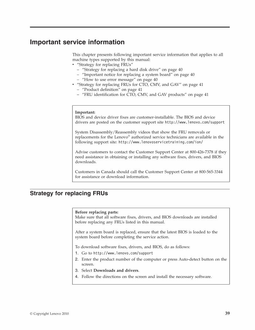
Important service information
This chapter presents following important service information that applies to allmachine types supported by this manual:v “Strategy for replacing FRUs”
– “Strategy for replacing a hard disk drive” on page 40– “Important notice for replacing a system board” on page 40– “How to use error message” on page 40
v “Strategy for replacing FRUs for CTO, CMV, and GAV” on page 41– “Product definition” on page 41– “FRU identification for CTO, CMV, and GAV products” on page 41
Strategy for replacing FRUs
Important:BIOS and device driver fixes are customer-installable. The BIOS and devicedrivers are posted on the customer support site http://www.lenovo.com/support
System Disassembly/Reassembly videos that show the FRU removals orreplacements for the Lenovo® authorized service technicians are available in thefollowing support site: http://www.lenovoservicetraining.com/ion/
Advise customers to contact the Customer Support Center at 800-426-7378 if theyneed assistance in obtaining or installing any software fixes, drivers, and BIOSdownloads.
Customers in Canada should call the Customer Support Center at 800-565-3344for assistance or download information.
Before replacing parts:Make sure that all software fixes, drivers, and BIOS downloads are installedbefore replacing any FRUs listed in this manual.
After a system board is replaced, ensure that the latest BIOS is loaded to thesystem board before completing the service action.
To download software fixes, drivers, and BIOS, do as follows:1. Go to http://www.lenovo.com/support
2. Enter the product number of the computer or press Auto-detect button on thescreen.
3. Select Downloads and drivers.4. Follow the directions on the screen and install the necessary software.
© Copyright Lenovo 2010 39
Use the following strategy to prevent unnecessary expense for replacing andservicing FRUs:v If you are instructed to replace a FRU but the replacement does not correct the
problem, reinstall the original FRU before you continue.v Some computers have both a processor board and a system board. If you are
instructed to replace either the processor board or the system board, andreplacing one of them does not correct the problem, reinstall that board, andthen replace the other one.
v If an adapter or a device consists of more than one FRU, any of the FRUs maybe the cause of the error. Before replacing the adapter or device, remove theFRUs, one by one, to see if the symptoms change. Replace only the FRU thatchanged the symptoms.
Attention: The setup configuration on the computer you are servicing may havebeen customized. Running Automatic Configuration may alter the settings. Notethe current configuration settings (using the View Configuration option); then,when service has been completed, verify that those settings remain in effect.
Strategy for replacing a hard disk driveAlways try to run a low-level format before replacing a hard disk drive. This willcause all customer data on the hard disk to be lost. Be sure that the customer has acurrent backup of the data before doing this task.
Attention: The drive startup sequence in the computer you are servicing mayhave been changed. Be extremely careful during write operations such as copying,saving, or formatting. If you select an incorrect drive, data or programs can beoverwritten.
Important notice for replacing a system boardSome components mounted on a system board are very sensitive. Improperhandling of a system board can cause damage to those components, and maycause a system malfunction.
Attention: When handling a system board:v Do not drop a system board or apply any excessive force to it.v Avoid rough handling of any kind.v Avoid bending a system board and hard pushing to prevent cracking at each
BGA (Ball Grid Array) chipset.
How to use error messageUse the error codes displayed on the screen to diagnose failures. If more than oneerror code is displayed, begin the diagnosis with the first error code. Whatevercauses the first error code may also cause false error codes. If no error code isdisplayed, see whether the error symptom is listed in the Symptom-to-FRU Indexfor the computer you are servicing.
40 ThinkPad T410 Hardware Maintenance Manual
Strategy for replacing FRUs for CTO, CMV, and GAV
Product definitionDynamic Configure To Order (CTO)
This provides the ability for a customer to configure an IBM® or a Lenovo solutionfrom an eSite, and have this configuration sent to fulfillment, where it is built andshipped directly to the customer. The machine label, Product EntitlementWarehouse (PEW), eSupport, and the HMM will load these products as the 4-digitMT and 3-digit model, where model = “CTO” (Example: 1829-CTO).
Custom Model Variant (CMV)
This is a unique configuration that has been negotiated between IBM or Lenovoand the customer. A unique 4-digit MT and 3-digit model is provided to thecustomer to place orders (Example: 1829-W15). A CMV is a special bid offering.Therefore, it is NOT generally announced.v The MTM portion of the machine label is the 4-digit MT and 3-digit model,
where model = “CTO” (Example: 1829-CTO). The PRODUCT ID portion of themachine label is the 4-digit MT and 3-digit CMV model (Example: 1829-W15).
v The PEW record is the 4-digit MT and 3-digit model, where model = “CTO”(Example: 1829-CTO).
v eSupport will show both the CTO and CMV machine type models (Example:1829-CTO and 1829-W15 will be found on the eSupport site.)
v The HMM will have the 4-digit MT and 3-digit CTO model only (Example:1829-CTO). Again, CMVs are custom models and are not found in the HMM.
General Announce Variant (GAV)
This is a standard model (fixed configuration). GAVs are announced and offered toall customers. The MTM portion of the machine label is a 4-digit MT and 3-digitmodel, where model = a “fixed part number”, not “CTO” (Example: 1829-F1U).Also, PEW, eSupport, and the HMM will list these products under the same fixedmodel number.
FRU identification for CTO, CMV, and GAV productsThere are three information resources to identify which FRUs are used to supportCTO, CMV, and GAV products. These sources are PEW, eSupport, and the HMM.
Using PEWv PEW is the primary source for identifying FRU part numbers and FRU
descriptions for the key commodities for CTO, CMV and GAV products at a MT- serial number level. An example of key commodities are hard disk drives,system boards, microprocessors, Liquid Crystal Displays (LCDs), and memory.
v Remember, all CTO and CMV products are loaded in PEW under the 4-digit MTand 3-digit model, where model = “CTO” (Example: 1829-CTO). GAVs areloaded in PEW under the 4-digit MT and 3-digit model, where model = a “fixedpart number”, not “CTO” (Example: 1829-F1U).
v PEW can be accessed at the following Web site:http://www.lenovo.com/support/site.wss/document.do?lndocid=LOOK-WARNTYSelect Warranty lookup. Input the MT and the Serial number and the list of keycommodities will be returned in the PEW record under COMPONENTINFORMATION.
Important service information 41
v Business Partners using Eclaim will access PEW when performing EntitlementLookup. Business Partners will enter Loc ID, MT and Serial, and the keycommodities will be returned in the Eclaim record under SYSTEM DETAILS.
v Authorized IBM Business Partners can access Eclaim at the following Web site:https://wca.eclaim.com
Using eSupport
For Key Commodities (Examples - hard disk drive, system board,microprocessor, LCD, and memory)
v eSupport can be used to view the list of key commodities built in a particularmachine serial (this is the same record found in PEW).
v eSupport can be accessed at the following Web site: http://www.lenovo.com/support
v To view the key commodities, click on PARTS INFORMATION, then PARTSLOOKUP. Type in the model type and serial number. The key commodities willbe returned in the eSupport record under PARTS SHIPPED WITH YOURSYSTEM.
For the Remaining FRUs (the complete list of FRUs at the MT Model level)
v eSupport can be used to view the complete list of FRUs for a machine type andmodel.
v To view the complete list of FRUs, type in the machine type and model(Example: 1829-CTO) under QUICK PATH. Under “View by Document Type”select PARTS INFORMATION. Under “Filter by Category” select SERVICEPARTS. Under “Parts Information by Date” select SYSTEM SERVICE PARTS. Thelist of service parts by description, with applicable machine type model and FRUwill be displayed.
Using the HMM
For Key Commodities (Examples - hard disk drive, system board,microprocessor, LCD, and memory)
Use the HMM as a back-up to PEW and eSupport to view the complete list ofFRUs at the MT Model level.
42 ThinkPad T410 Hardware Maintenance Manual
General checkout
This chapter presents following information:v “What to do first” on page 44v “Checkout guide” on page 45
– “Diagnostics using PC-Doctor for DOS” on page 45– “Lenovo ThinkVantage Toolbox (Lenovo System Toolbox)” on page 48– “PC-Doctor for Rescue and Recovery” on page 48– “FRU tests” on page 49
v “Power system checkout” on page 51
The descriptions in this chapter apply to any ThinkPad model that supports thePC-Doctor® for DOS diagnostics program. Some descriptions might not apply toyour particular computer.
Before you go to the checkout guide, be sure to read the following important notes.
Important notes:
v Only certified trained personnel should service the computer.
v Before replacing any FRU, read the entire page on removing and replacingFRUs.
v When you replace FRUs, use new nylon-coated screws.
v Be extremely careful during such write operations as copying, saving, orformatting. Drives in the computer that you are servicing sequence mighthave been altered. If you select an incorrect drive, data or programs might beoverwritten.
v Replace a FRU only with another FRU of the correct model. When youreplace a FRU, make sure that the model of the machine and the FRU partnumber are correct by referring to the FRU parts list.
v A FRU should not be replaced because of a single, unreproducible failure.Single failures can occur for a variety of reasons that have nothing to do witha hardware defect, such as cosmic radiation, electrostatic discharge, orsoftware errors. Consider replacing a FRU only when a problem recurs. If yoususpect that a FRU is defective, clear the error log and run the test again. Ifthe error does not recur, do not replace the FRU.
v Be careful not to replace a nondefective FRU.
© Copyright Lenovo 2010 43
What to do firstWhen you do return a FRU, you must include the following information in theparts exchange form or parts return form that you attach to it:__ 1. Name and phone number of service technician__ 2. Date of service__ 3. Date on which the machine failed__ 4. Date of purchase__ 5. Failure symptoms, error codes appearing on the display, and beep
symptoms__ 6. Procedure index and page number in which the failing FRU was detected__ 7. Failing FRU name and part number__ 8. Machine type, model number, and serial number__ 9. Customer’s name and address
Note for warranty: During the warranty period, the customer may be responsiblefor repair costs if the computer damage was caused by misuse, accident,modification, unsuitable physical or operating environment, or impropermaintenance by the customer.
Following is a list of some common items that are not covered under warranty andsome symptoms that might indicate that the system was subjected to stress beyondnormal use.
Before checking problems with the computer, determine whether the damage iscovered under the warranty by referring to the following list:
The following are not covered under warranty:v LCD panel cracked from the application of excessive force or from being
droppedv Scratched (cosmetic) partsv Distortion, deformation, or discoloration of the cosmetic partsv Plastic parts, latches, pins, or connectors that have been cracked or broken by
excessive forcev Damage caused by liquid spilled into the systemv Damage caused by the improper insertion of a PC Card or the installation of an
incompatible cardv Improper disc insertion or use of an optical drivev Diskette drive damage caused by pressure on the diskette drive cover, foreign
material in the drive, or the insertion of a diskette with multiple labelsv Damaged or bent diskette eject buttonv Fuses blown by attachment of a nonsupported devicev Forgotten computer password (making the computer unusable)v Sticky keys caused by spilling a liquid onto the keyboardv Use of an incorrect ac adapter on laptop products
The following symptoms might indicate damage caused by nonwarrantedactivities:v Missing parts might be a symptom of unauthorized service or modification.v If the spindle of a hard disk drive becomes noisy, it may have been subjected to
excessive force, or dropped.
44 ThinkPad T410 Hardware Maintenance Manual
Checkout guideUse the following procedures as a guide in identifying and correcting problemswith the ThinkPad Notebook.
Note: The diagnostic tests are intended to test only ThinkPad products. The use ofnon-ThinkPad products, prototype cards, or modified options can lead to falseindications of errors and invalid system responses.1. Identify the failing symptoms in as much detail as possible.2. Verify the symptoms. Try to re-create the failure by running the diagnostic test
or by repeating the operation.
Diagnostics using PC-Doctor for DOSThe ThinkPad Notebook has a test program called PC-Doctor for DOS (hereaftercalled PC-Doctor.) You can detect errors by running the diagnostics test included inPC-Doctor.
For some possible configurations of the computer, PC-Doctor might not runcorrectly. To avoid this problem, you need to initialize the computer setup by useof the BIOS Setup Utility before you run PC-Doctor.
To enter BIOS Setup Utility, do as follows:1. Turn on the computer.2. When the ThinkPad logo comes up, immediately press F1 to enter the BIOS
Setup Utility.
Note: If a supervisor password has been set by the customer, BIOS Setup Utilitymenu appears after the password is entered. You can start the utility by pressingEnter instead of entering the supervisor password; however, you cannot change theparameters that are protected by the supervisor password.
On the BIOS Setup Utility screen, press F9, Enter, F10, and then Enter.
Note: When you initialize the computer configuration, some devices are disabled,such as the serial port. If you test one of these devices, you will need to enable itby using Configuration utility for DOS. The utility is available on the followingWeb site: http://www.lenovo.com/support
PC-Doctor cannot be used to test a device that is in the docking station, even if thecomputer supports the docking station. To test a USB device, connect it to the USBconnector of the computer.
Note:PC-Doctor for DOS is available at the following Web site: http://www.lenovo.com/support
To create the PC-Doctor diagnostic CD, follow the instructions on the Web site.
General checkout 45
Testing the computer
Note: The PC-Doctor diagnostic CD does not support any optical drives connectedthrough USB devices or any others. It supports only the internal optical drive ofthe ThinkPad Notebook.
To run the test, do as follows:1. Turn off the computer.2. Make sure that the internal optical drive that is supported as a startup device
is attached to the computer.3. Turn on the computer.
If the computer cannot be powered on, go to “Power system checkout” onpage 51, and check the power sources.If an error code appears, go to “Symptom-to-FRU index” on page 62.
4. When the ThinkPad logo comes up, immediately press F12 to enter the BootMenu.
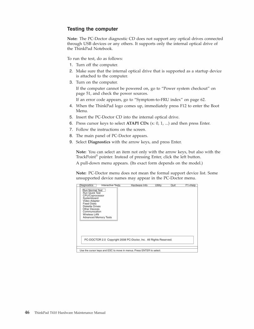
5. Insert the PC-Doctor CD into the internal optical drive.6. Press cursor keys to select ATAPI CDx (x: 0, 1, ...) and then press Enter.7. Follow the instructions on the screen.8. The main panel of PC-Doctor appears.9. Select Diagnostics with the arrow keys, and press Enter.
Note: You can select an item not only with the arrow keys, but also with theTrackPoint® pointer. Instead of pressing Enter, click the left button.A pull-down menu appears. (Its exact form depends on the model.)
Note: PC-Doctor menu does not mean the formal support device list. Someunsupported device names may appear in the PC-Doctor menu.
Diagnostics
Run Normal TestRun Quick TestCPU/CoprocessorSystemboardVideo AdapterFixed DisksDiskette DrivesOther DevicesCommunication
Advanced Memory Tests
Interactive Tests Hardware Info Utility Quit F1=Help
PC-DOCTOR 2.0 Copyright 2008 PC-Doctor, Inc. All Rights Reserved.
Use the cursor keys and ESC to move in menus. Press ENTER to select.
Wireless LAN
46 ThinkPad T410 Hardware Maintenance Manual
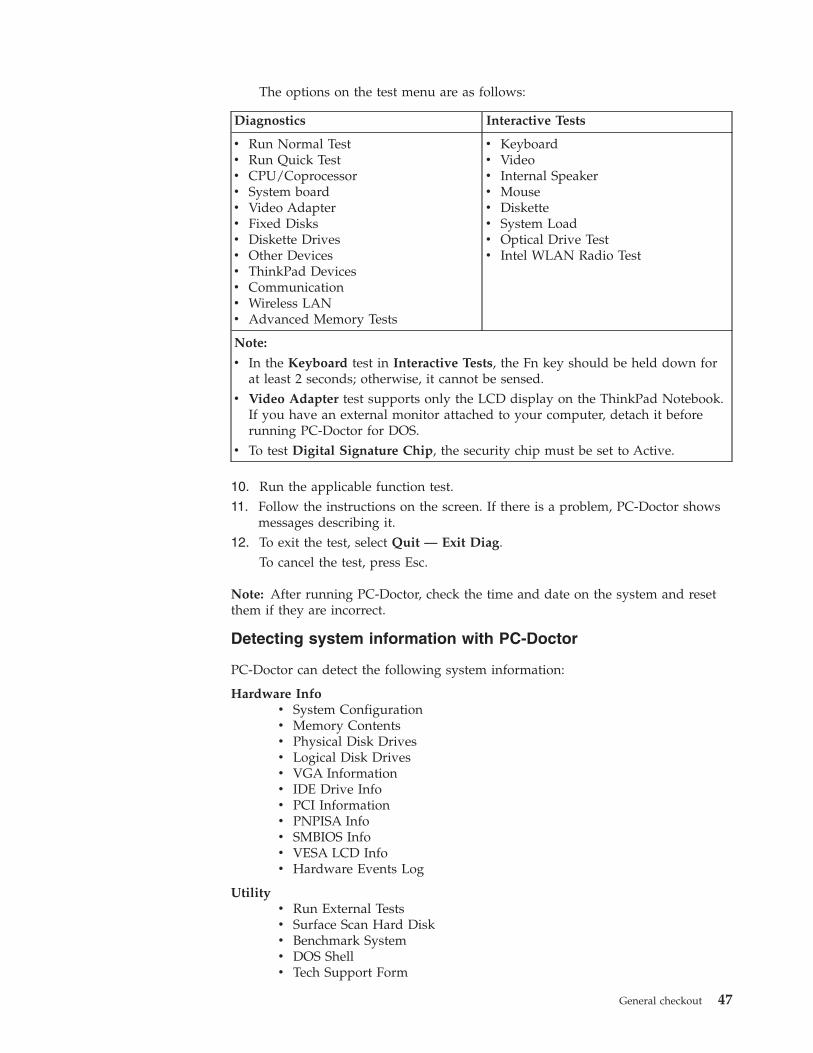
The options on the test menu are as follows:
Diagnostics Interactive Tests
v Run Normal Testv Run Quick Testv CPU/Coprocessorv System boardv Video Adapterv Fixed Disksv Diskette Drivesv Other Devicesv ThinkPad Devicesv Communicationv Wireless LANv Advanced Memory Tests
v Keyboardv Videov Internal Speakerv Mousev Diskettev System Loadv Optical Drive Testv Intel WLAN Radio Test
Note:
v In the Keyboard test in Interactive Tests, the Fn key should be held down forat least 2 seconds; otherwise, it cannot be sensed.
v Video Adapter test supports only the LCD display on the ThinkPad Notebook.If you have an external monitor attached to your computer, detach it beforerunning PC-Doctor for DOS.
v To test Digital Signature Chip, the security chip must be set to Active.
10. Run the applicable function test.11. Follow the instructions on the screen. If there is a problem, PC-Doctor shows
messages describing it.12. To exit the test, select Quit — Exit Diag.
To cancel the test, press Esc.
Note: After running PC-Doctor, check the time and date on the system and resetthem if they are incorrect.
Detecting system information with PC-Doctor
PC-Doctor can detect the following system information:
Hardware Infov System Configurationv Memory Contentsv Physical Disk Drivesv Logical Disk Drivesv VGA Informationv IDE Drive Infov PCI Informationv PNPISA Infov SMBIOS Infov VESA LCD Infov Hardware Events Log
Utilityv Run External Testsv Surface Scan Hard Diskv Benchmark Systemv DOS Shellv Tech Support Form
General checkout 47
v Battery Rundownv View Test Logv Print Logv Save Logv Full Erase Hard Drivev Quick Erase Hard Drive
Lenovo ThinkVantage Toolbox (Lenovo System Toolbox)
Lenovo ThinkVantage® Toolbox (Lenovo System Toolbox in Windows Vista® andWindows® XP) is a diagnostic program that works through the Windows operatingsystem. It enables you to view symptoms of computer problems and solutions forthem, and includes automatic notification when action is required, computingassistance, advanced diagnostics, and diagnostic history.
To run this program, do as follows:
Windows 7:While the Windows operating system is running, press the ThinkVantage button.
You can also run this program as either of the following:v Click Start --> All Programs --> Lenovo ThinkVantage Tools --> System Health
and Diagnostics.v Click Start --> Control Panel --> System and Security --> Lenovo’s System
Health and Diagnostics.
Windows Vista and Windows XP:Click Start --> All Programs --> Lenovo Services --> Lenovo System Toolbox.
Follow the instructions on the screen. Lenovo ThinkVantage Toolbox (LenovoSystem Toolbox) also has problem determination aids that determine software andusage problems.
For additional information about this program, see the Help for the program.
PC-Doctor for Rescue and Recovery
In some models of ThinkPad Notebook, the Rescue and Recovery® workspaceenables you to run the PC-Doctor program to test the hardware features of thecomputer.
To run the test, click “Run Diagnostics” on the Rescue and Recovery main screen.
Note:The latest Lenovo ThinkVantage Toolbox (Lenovo System Toolbox) is available atthe following Web site: http://www.lenovo.com/support
To install the latest Lenovo ThinkVantage Toolbox (Lenovo System Toolbox) onthe computer, follow the instructions on the Web site.
48 ThinkPad T410 Hardware Maintenance Manual
FRU tests
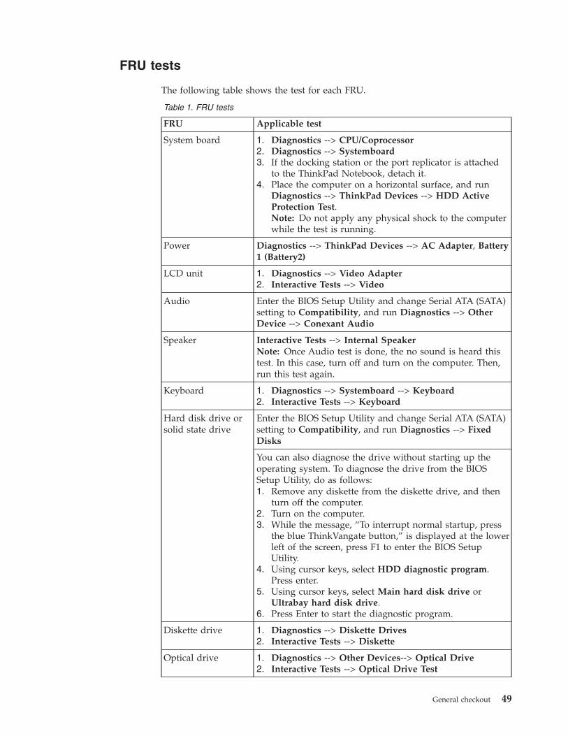
The following table shows the test for each FRU.
Table 1. FRU tests
FRU Applicable test
System board 1. Diagnostics --> CPU/Coprocessor2. Diagnostics --> Systemboard3. If the docking station or the port replicator is attached
to the ThinkPad Notebook, detach it.4. Place the computer on a horizontal surface, and run
Diagnostics --> ThinkPad Devices --> HDD ActiveProtection Test.Note: Do not apply any physical shock to the computerwhile the test is running.
Power Diagnostics --> ThinkPad Devices --> AC Adapter, Battery1 (Battery2)
LCD unit 1. Diagnostics --> Video Adapter2. Interactive Tests --> Video
Audio Enter the BIOS Setup Utility and change Serial ATA (SATA)setting to Compatibility, and run Diagnostics --> OtherDevice --> Conexant Audio
Speaker Interactive Tests --> Internal SpeakerNote: Once Audio test is done, the no sound is heard thistest. In this case, turn off and turn on the computer. Then,run this test again.
Keyboard 1. Diagnostics --> Systemboard --> Keyboard2. Interactive Tests --> Keyboard
Hard disk drive orsolid state drive
Enter the BIOS Setup Utility and change Serial ATA (SATA)setting to Compatibility, and run Diagnostics --> FixedDisks
You can also diagnose the drive without starting up theoperating system. To diagnose the drive from the BIOSSetup Utility, do as follows:1. Remove any diskette from the diskette drive, and then
turn off the computer.2. Turn on the computer.3. While the message, “To interrupt normal startup, press
the blue ThinkVangate button,” is displayed at the lowerleft of the screen, press F1 to enter the BIOS SetupUtility.
4. Using cursor keys, select HDD diagnostic program.Press enter.
5. Using cursor keys, select Main hard disk drive orUltrabay hard disk drive.
6. Press Enter to start the diagnostic program.
Diskette drive 1. Diagnostics --> Diskette Drives2. Interactive Tests --> Diskette
Optical drive 1. Diagnostics --> Other Devices--> Optical Drive2. Interactive Tests --> Optical Drive Test
General checkout 49
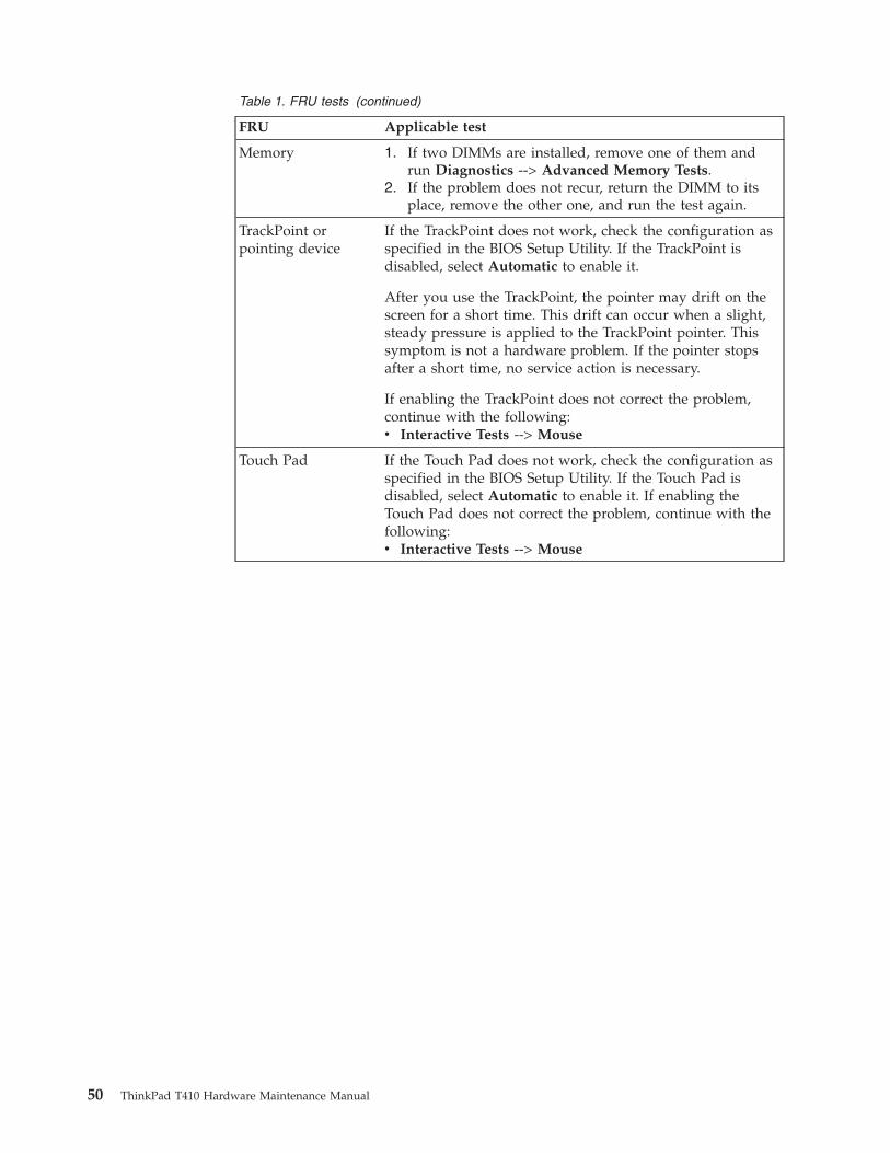
Table 1. FRU tests (continued)
FRU Applicable test
Memory 1. If two DIMMs are installed, remove one of them andrun Diagnostics --> Advanced Memory Tests.
2. If the problem does not recur, return the DIMM to itsplace, remove the other one, and run the test again.
TrackPoint orpointing device
If the TrackPoint does not work, check the configuration asspecified in the BIOS Setup Utility. If the TrackPoint isdisabled, select Automatic to enable it.
After you use the TrackPoint, the pointer may drift on thescreen for a short time. This drift can occur when a slight,steady pressure is applied to the TrackPoint pointer. Thissymptom is not a hardware problem. If the pointer stopsafter a short time, no service action is necessary.
If enabling the TrackPoint does not correct the problem,continue with the following:v Interactive Tests --> Mouse
Touch Pad If the Touch Pad does not work, check the configuration asspecified in the BIOS Setup Utility. If the Touch Pad isdisabled, select Automatic to enable it. If enabling theTouch Pad does not correct the problem, continue with thefollowing:v Interactive Tests --> Mouse
50 ThinkPad T410 Hardware Maintenance Manual
Power system checkoutTo verify a symptom, do the following:1. Turn off the computer.2. Remove the battery pack.3. Connect the ac adapter.4. Check that power is supplied when you turn on the computer.5. Turn off the computer.6. Disconnect the ac adapter and install the charged battery pack.7. Check that the battery pack supplies power when you turn on the computer.
If you suspect a power problem, see the appropriate one of the following powersupply checkouts:v “Checking the AC adapter”v “Checking operational charging” on page 52v “Checking the battery pack” on page 52v “Checking the backup battery” on page 53
Checking the AC adapterYou are here because the computer fails only when the AC adapter is used.v If the power problem occurs only when the docking station or the port replicator
is used, replace the docking station or the port replicator.v If the power-on indicator does not turn on, check the power cord of the AC
adapter for correct continuity and installation.v If the computer does not charge during operation, go to “Checking operational
charging” on page 52.
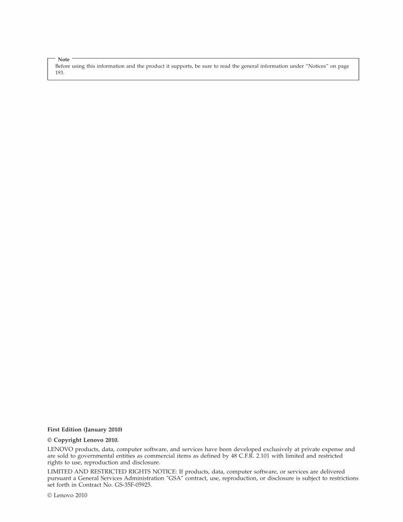
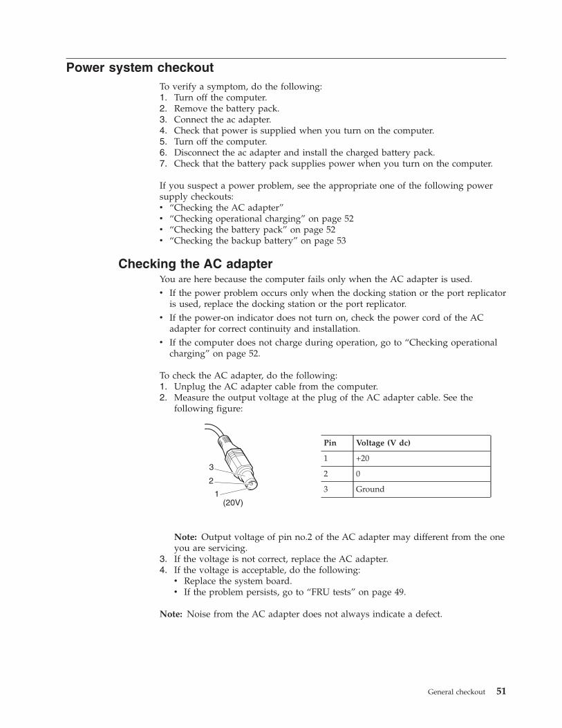
To check the AC adapter, do the following:1. Unplug the AC adapter cable from the computer.2. Measure the output voltage at the plug of the AC adapter cable. See the
following figure:
1
2
3
(20V)
Pin Voltage (V dc)
1 +20
2 0
3 Ground
Note: Output voltage of pin no.2 of the AC adapter may different from the oneyou are servicing.
3. If the voltage is not correct, replace the AC adapter.4. If the voltage is acceptable, do the following:v Replace the system board.v If the problem persists, go to “FRU tests” on page 49.
Note: Noise from the AC adapter does not always indicate a defect.
General checkout 51

Checking operational chargingTo check whether the battery charges properly during operation, use a dischargedbattery pack or a battery pack that has less than 50% of the total power remainingwhen installed in the computer.
Perform operational charging. If the battery status indicator or icon does not turnon, remove the battery pack and let it return to room temperature. Reinstall thebattery pack. If the charge indicator or icon still does not turn on, replace thebattery pack.
If the charge indicator still does not turn on, replace the system board. Thenreinstall the battery pack. If it is still not charged, go to the next section.
Checking the battery packBattery charging does not start until the Power Manager Battery Gauge shows thatless than 96% of the total power remains; under this condition the battery pack cancharge to 100% of its capacity. This protects the battery pack from beingovercharged or from having a shortened life.
To check your battery, move your cursor to the Power Manager Battery Gauge iconin the icon tray of the Windows taskbar and wait for a moment (but do not click),and the percentage of battery power remaining is displayed. To get detailedinformation about the battery, double-click the Power Manager Battery Gauge icon.
Note: If the battery pack becomes hot, it may not be able to charge. Remove itfrom the computer and leave it at room temperature for a while. After it coolsdown, reinstall and recharge it.
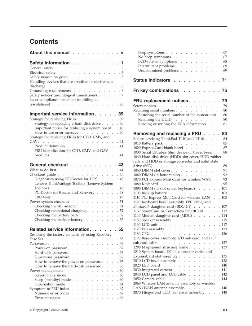
To check the battery pack, do the following:1. Power off the computer.2. Remove the battery pack and measure the voltage between battery terminals 1
(+) and 7 (-). See the following figure:
1(+)2(+)
3 4 5 6(-)7(-)
Terminal Voltage (V dc)
1 + 0 to + 16.8
7 Ground (-)
3. If the voltage is less than +11.0 V dc, the battery pack has been discharged.
Note: Recharging will take at least 3 hours, even if the indicator does not turnon.If the voltage is still less than +11.0 V dc after recharging, replace the battery.
4. If the voltage is more than +11.0 V dc, measure the resistance between batteryterminals 5 and 7. The resistance must be 4 to 30 K �.If the resistance is not correct, replace the battery pack. If the resistance iscorrect, replace the system board.
52 ThinkPad T410 Hardware Maintenance Manual
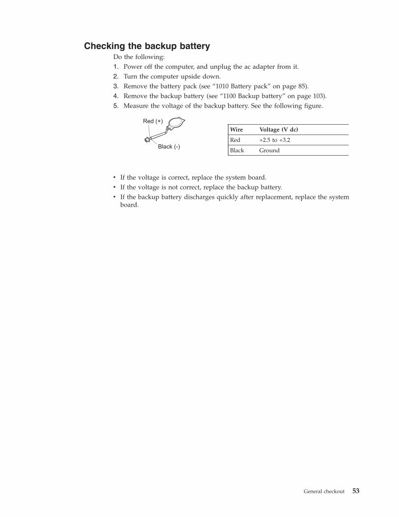
Checking the backup batteryDo the following:1. Power off the computer, and unplug the ac adapter from it.2. Turn the computer upside down.3. Remove the battery pack (see “1010 Battery pack” on page 85).4. Remove the backup battery (see “1100 Backup battery” on page 103).5. Measure the voltage of the backup battery. See the following figure.
Red (+)
Black (-)
Wire Voltage (V dc)
Red +2.5 to +3.2
Black Ground
v If the voltage is correct, replace the system board.v If the voltage is not correct, replace the backup battery.v If the backup battery discharges quickly after replacement, replace the system
board.
General checkout 53

54 ThinkPad T410 Hardware Maintenance Manual
Related service information
This chapter presents following information:v “Restoring the factory contents by using Recovery Disc Set”v “Passwords” on page 56v “Power management” on page 60v “Symptom-to-FRU index” on page 62
Restoring the factory contents by using Recovery Disc SetWhen the hard disk drive (HDD) or solid state drive (SSD) is replaced because of afailure, no product recovery program is on the new drive. In this case, you mustuse the Recovery Disc Set for the computer. Order the Recovery Disc Set and thedrive at the same time so that you can recover the new drive with the pre-installedsoftware when they arrive. For information on which discs to order, see “Recoverydiscs” on page 183.
The recovery disc set consists of the user instructions and the following set ofDVDs to restore the computer to the original factory configuration.
Operating System Recovery Disc (one disc)This disc restores the Microsoft® Windows operating system. Use this discto start the recovery process.
Applications and Drivers Recovery Disc (one or more discs)This disc restores the preinstalled applications and drivers on thecomputer.
Supplemental Recovery DiscThis disc contains additional content, such as updates to the software thatwas preinstalled on the computer. Not all recovery disc sets come with aSupplemental Recovery Disc.
Notes:
v You must have a DVD drive to use the recovery discs. If you do not have aninternal DVD drive, you can use an external USB DVD drive.
v During the recovery process, all data on the drive will be deleted. If possible,copy any important data or personal files that you want to keep onto removablemedia or a network drive before you start the recovery process.
To restore the computer to the original factory configuration using the recoverydisc set, do the following:
Service Web site:When the latest maintenance diskette and the system program service diskettebecome available, they will be posted on http://www.lenovo.com/spm
© Copyright Lenovo 2010 55
1. Make the CD/DVD drive the first startup device in the startup sequenceusing the following procedure:a. Press and hold down the F1 key, and then turn on the computer. When the
logo screen is displayed or if you hear repeating beeps, release the F1 key.The Setup Utility program opens.
b. Use the arrow keys to select Startup → Boot.c. Select the CD/DVD drive as the 1st Boot Device.
2. Insert the Operating System Recovery Disc into the DVD drive.3. Press F10 to save the Setup Utility configuration changes. Follow the
instructions on the screen to begin the recovery process.4. Select your language and click Next.5. Read the license. If you agree with the terms and conditions, select I accept
these terms and conditions and then click Next. If you do not agree with theterms and conditions, follow the instructions on the screen.
6. Click Yes in the displayed window to begin the operating system recoveryprocess.
7. Insert the Applications and Drivers Recovery Disc when prompted and then clickOK to begin the applications and drivers recovery process.
8. If you have a Supplemental Recovery Disc, insert it when prompted and clickYes. If you do not have a Supplemental Recovery Disc, click No.
9. When all of the data has been copied from the last disc in the set and hasbeen processed, remove the disc and restart the computer.
Note: The rest of the recovery process is fully automated and no action isrequired by you. The computer will restart into the Microsoft Windowsdesktop several times and you might experience periods when no activity isapparent on the screen for several minutes at a time. This is normal.
10. When the recovery process is complete, the Set Up Windows screen isdisplayed. Follow the instructions on the screen to complete the Windowssetup.
11. After you have completed the Windows setup, you might want to restore theoriginal startup sequence. Start the Setup Utility program and then press F9 torestore the default settings. Press F10 to save and exit the Setup Utility.
Note: After restoring a drive to the factory default settings, you might need toreinstall some device drivers.
PasswordsAs many as three passwords may be needed for any ThinkPad Notebook: thepower-on password (POP), the hard-disk password (HDP), and the supervisorpassword (SVP).
If any of these passwords has been set, a prompt for it appears on the screenwhenever the computer is turned on. The computer does not start until thepassword is entered.
Note: Recovery takes several hours. The length of time depends on the methodyou use. If you use recovery discs, recovery takes at least five hours.
56 ThinkPad T410 Hardware Maintenance Manual
Exception: If only an SVP is installed, the password prompt does not appear whenthe operating system is booted.
Power-on password
A power-on password (POP) protects the system from being powered on by anunauthorized person. The password must be entered before an operating systemcan be booted. For how to remove the POP, see “How to remove the power-onpassword.”
Hard-disk password
There are two hard-disk passwords (HDPs):v User HDP—for the userv Master HDP—for the system administrator, who can use it to get access to the
hard disk even if the user has changed the user HDP
Note: There are two modes for the HDP: User only and Master + User. TheMaster + User mode requires two HDPs; the system administrator enters both inthe same operation. The system administrator then provides the user HDP to thesystem user.
Attention: If the user HDP has been forgotten, check whether a master HDP hasbeen set. If it has, it can be used for access to the hard disk drive. If no masterHDP is available, neither Lenovo nor Lenovo authorized service techniciansprovide any services to reset either the user or the master HDP, or to recover datafrom the hard disk drive. The hard disk drive can be replaced for a scheduled fee.
For how to remove the POP, see “How to remove the hard-disk password” onpage 58.
Supervisor password
A supervisor password (SVP) protects the system information stored in the BIOSSetup Utility. The user must enter the SVP in order to get access to the BIOS SetupUtility and change the system configuration.
Attention: If the SVP has been forgotten and cannot be made available to theservice technician, there is no service procedure to reset the password. The systemboard must be replaced for a scheduled fee.
How to remove the power-on passwordTo remove a POP that you have forgotten, do the following:
(A) If no SVP has been set:
1. Turn off the computer.2. Remove the battery pack.
For how to remove the battery pack, see “1010 Battery pack” on page 85.3. Remove the backup battery.
For how to remove the backup battery, see “1100 Backup battery” on page 103.4. Turn on the computer and wait until the POST ends.
Related service information 57
After the POST ends, the password prompt does not appear. The POP has beenremoved.
5. Reinstall the backup battery and the battery pack.
(B) If an SVP has been set and is known by the service technician:
1. Turn on the computer.2. When the ThinkPad logo comes up, immediately press F1 to enter BIOS Setup
Utility.For models supporting the Passphrase function, press F1 while the POP icon isappearing on the screen; then enter the POP. For the other models, enter thePOP.
Note: To check whether the ThinkPad Notebook you are servicing supports thePassphrase function, enter the BIOS Setup Utility and go to Security -->Password. If the Using Passphrase item is displayed in the menu, this functionis available on the ThinkPad Notebook.
3. Select Security, using the cursor directional keys to move down the menu.4. Select Password.5. Select Power-On Password.6. Type the current SVP in the Enter Current Password field. then leave the Enter
New Password field blank, and press Enter twice.7. In the Changes have been saved window, press Enter.8. Press F10; then, in the Setup confirmation window, select Yes.
How to remove the hard-disk password
Attention: If User only mode is selected and the user HDP has been forgottenand cannot be made available to the service technician, neither Lenovo nor Lenovoauthorized service technicians provide any services to reset the user HDPs or torecover data from the hard disk drive. The hard disk drive can be replaced for ascheduled fee.
To remove a user HDP that has been forgotten, when the SVP and the master HDPare known, do the following:1. Turn on the computer.2. When the ThinkPad logo comes up, immediately press F1 to enter BIOS Setup
Utility.For models supporting the Passphrase function, press F1 while HDP icon isappearing on the screen; then enter the master HDP. For the other models,enter the master HDP.
Note: To check whether the ThinkPad Notebook you are servicing supports thePassphrase function, enter the BIOS Setup Utility and go to Security -->Password. If Using Passphrase item is displayed in the menu, this function isavailable on the ThinkPad Notebook.
3. Select Security, using the cursor directional keys to move down the menu.4. Select Password.5. Select Hard-disk x password, where x is the letter of the hard disk drive. A
pop-up window opens.6. Select Master HDP.
58 ThinkPad T410 Hardware Maintenance Manual
7. Type the current master HDP in the Enter Current Password field. then leavethe Enter New Password field blank, and press Enter twice.
8. Press F10.9. Select Yes in the Setup Configuration window.
Both user HDP and master HDP will have been removed.
Related service information 59
Power managementTo reduce power consumption, the computer has three power management modes:screen blank, sleep (standby in Windows XP), and hibernation.
Screen blank mode
If the time set on the “Turn off monitor” timer in the operating system expires, theLCD backlight turns off.
To put the computer into screen blank mode, do as follows:1. Press Fn+F3. A panel for selecting a power plan (in Windows XP, power
scheme) appears.2. Select Power off display (keep current power plan) (in Windows XP, keep
current power scheme).
You can also put the computer into screen blank mode, press ThinkVantage buttonand use the ThinkVantage Productivity Center.
Note: If the computer is a Windows 7 model, it does not support ThinkVantageProductivity Center.
To end screen blank mode and resume normal operation, press any key.
Sleep (standby) mode
When the computer enters sleep (standby) mode, the following events occur inaddition to what occurs in screen blank mode:v The LCD is powered off.v The hard disk drive is powered off.v The CPU stops.
To enter sleep (standby) mode, press Fn+F4.
Note: You can change the action of the Fn+F4 key combination by changing thesettings in Power Manager.
In certain circumstances, the computer goes into sleep (standby) modeautomatically:v If a “suspend time” has been set on the timer, and the user does not do any
operation with the keyboard, the TrackPoint, the hard disk, the parallelconnector, or the diskette drive within that time.
v If the battery indicator blinks orange, indicating that the battery power is low.
Note: Even if you do not set the low-battery alarm, the charge indicator notifiesyou when the battery is low, and then the computer enters the power-saving modeautomatically.
To cause the computer to return from sleep (standby) mode and resume operation,do one of the following:v Press the Fn key.v Open the LCD cover.v Turn on the power switch.
60 ThinkPad T410 Hardware Maintenance Manual
Also, in either of the following events, the computer automatically returns fromsleep (standby) mode and resumes operation:v The ring indicator (RI) is signaled by a serial device or a PC Card device.v The time set on the resume timer elapses.
Note: The computer does not accept any input immediately after it enters sleep(standby) mode. Wait a few seconds before taking any action to reenteroperation mode.
Hibernation mode
In hibernation mode, the following occurs:v The system status, RAM, VRAM, and setup data are stored on the hard disk.v The system is powered off.
Note: If the computer enters the hibernation mode while it is docked to thedocking station, do not undock it before resuming normal operation. If you doundock it and then try to resume normal operation, you will get an error message,and you will have to restart the system.
To cause the computer to enter hibernation mode, do any of the following:v Press the Fn+F12 keys.v If you have defined one of the following actions as the event that causes the
system to go into hibernation mode, perform that action.– Closing the lid.– Pressing the power button.– Pressing Fn+F4 keys.
Also, the computer goes into hibernation mode automatically in either of thefollowing conditions:v If a “hibernation time” has been set on the timer, and if the user does not do
any operation with the keyboard, the TrackPoint, the hard disk drive, theparallel connector, or the diskette drive within that time.
v If the timer conditions are satisfied in suspend mode.
When the power is turned on, the computer returns from hibernation mode andresumes operation. The hibernation file in the boot record on the hard disk drive isread, and system status is restored from the hard disk drive.
Related service information 61
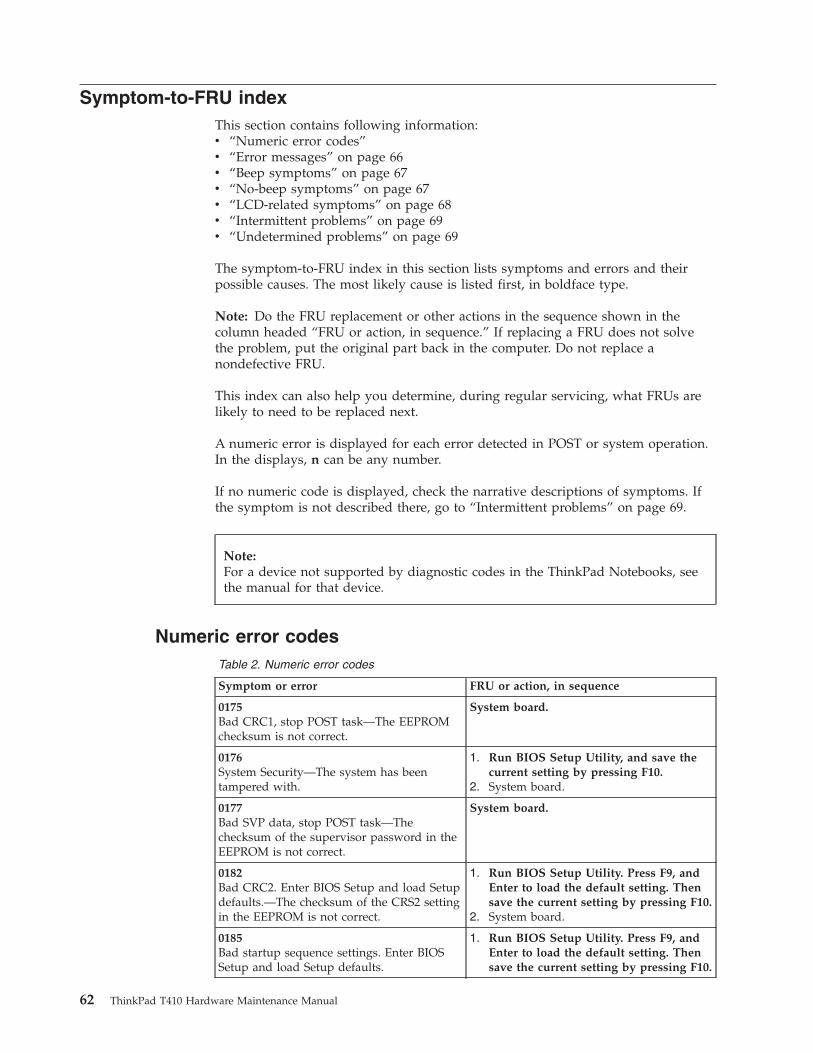
Symptom-to-FRU indexThis section contains following information:v “Numeric error codes”v “Error messages” on page 66v “Beep symptoms” on page 67v “No-beep symptoms” on page 67v “LCD-related symptoms” on page 68v “Intermittent problems” on page 69v “Undetermined problems” on page 69
The symptom-to-FRU index in this section lists symptoms and errors and theirpossible causes. The most likely cause is listed first, in boldface type.
Note: Do the FRU replacement or other actions in the sequence shown in thecolumn headed “FRU or action, in sequence.” If replacing a FRU does not solvethe problem, put the original part back in the computer. Do not replace anondefective FRU.
This index can also help you determine, during regular servicing, what FRUs arelikely to need to be replaced next.
A numeric error is displayed for each error detected in POST or system operation.In the displays, n can be any number.
If no numeric code is displayed, check the narrative descriptions of symptoms. Ifthe symptom is not described there, go to “Intermittent problems” on page 69.
Numeric error codesTable 2. Numeric error codes
Symptom or error FRU or action, in sequence
0175Bad CRC1, stop POST task—The EEPROMchecksum is not correct.
System board.
0176System Security—The system has beentampered with.
1. Run BIOS Setup Utility, and save thecurrent setting by pressing F10.
2. System board.
0177Bad SVP data, stop POST task—Thechecksum of the supervisor password in theEEPROM is not correct.
System board.
0182Bad CRC2. Enter BIOS Setup and load Setupdefaults.—The checksum of the CRS2 settingin the EEPROM is not correct.
1. Run BIOS Setup Utility. Press F9, andEnter to load the default setting. Thensave the current setting by pressing F10.
2. System board.
0185Bad startup sequence settings. Enter BIOSSetup and load Setup defaults.
1. Run BIOS Setup Utility. Press F9, andEnter to load the default setting. Thensave the current setting by pressing F10.
Note:For a device not supported by diagnostic codes in the ThinkPad Notebooks, seethe manual for that device.
62 ThinkPad T410 Hardware Maintenance Manual
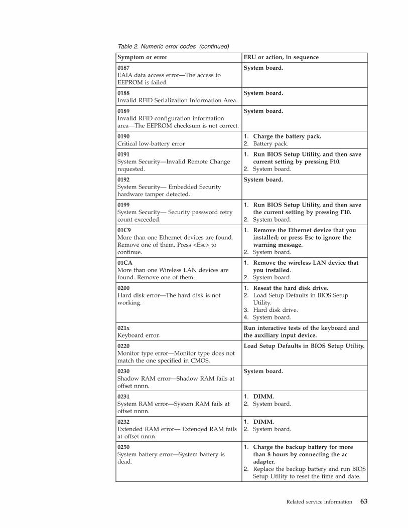
Table 2. Numeric error codes (continued)
Symptom or error FRU or action, in sequence
0187EAIA data access error—The access toEEPROM is failed.
System board.
0188Invalid RFID Serialization Information Area.
System board.
0189Invalid RFID configuration informationarea—The EEPROM checksum is not correct.
System board.
0190Critical low-battery error
1. Charge the battery pack.2. Battery pack.
0191System Security—Invalid Remote Changerequested.
1. Run BIOS Setup Utility, and then savecurrent setting by pressing F10.
2. System board.
0192System Security— Embedded Securityhardware tamper detected.
System board.
0199System Security— Security password retrycount exceeded.
1. Run BIOS Setup Utility, and then savethe current setting by pressing F10.
2. System board.
01C9More than one Ethernet devices are found.Remove one of them. Press <Esc> tocontinue.
1. Remove the Ethernet device that youinstalled; or press Esc to ignore thewarning message.
2. System board.
01CAMore than one Wireless LAN devices arefound. Remove one of them.
1. Remove the wireless LAN device thatyou installed.
2. System board.
0200Hard disk error—The hard disk is notworking.
1. Reseat the hard disk drive.2. Load Setup Defaults in BIOS Setup
Utility.3. Hard disk drive.4. System board.
021xKeyboard error.
Run interactive tests of the keyboard andthe auxiliary input device.
0220Monitor type error—Monitor type does notmatch the one specified in CMOS.
Load Setup Defaults in BIOS Setup Utility.
0230Shadow RAM error—Shadow RAM fails atoffset nnnn.
System board.
0231System RAM error—System RAM fails atoffset nnnn.
1. DIMM.2. System board.
0232Extended RAM error— Extended RAM failsat offset nnnn.
1. DIMM.2. System board.
0250System battery error—System battery isdead.
1. Charge the backup battery for morethan 8 hours by connecting the acadapter.
2. Replace the backup battery and run BIOSSetup Utility to reset the time and date.
Related service information 63
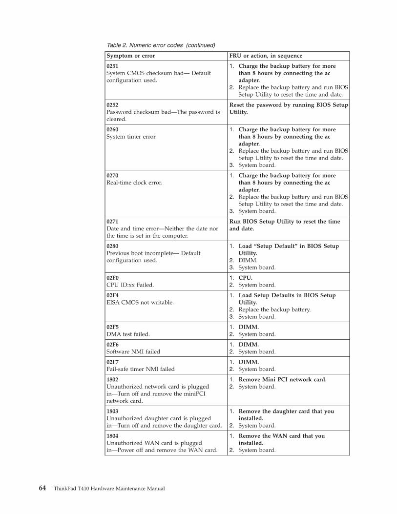
Table 2. Numeric error codes (continued)
Symptom or error FRU or action, in sequence
0251System CMOS checksum bad— Defaultconfiguration used.
1. Charge the backup battery for morethan 8 hours by connecting the acadapter.
2. Replace the backup battery and run BIOSSetup Utility to reset the time and date.
0252Password checksum bad—The password iscleared.
Reset the password by running BIOS SetupUtility.
0260System timer error.
1. Charge the backup battery for morethan 8 hours by connecting the acadapter.
2. Replace the backup battery and run BIOSSetup Utility to reset the time and date.
3. System board.
0270Real-time clock error.
1. Charge the backup battery for morethan 8 hours by connecting the acadapter.
2. Replace the backup battery and run BIOSSetup Utility to reset the time and date.
3. System board.
0271Date and time error—Neither the date northe time is set in the computer.
Run BIOS Setup Utility to reset the timeand date.
0280Previous boot incomplete— Defaultconfiguration used.
1. Load “Setup Default” in BIOS SetupUtility.
2. DIMM.3. System board.
02F0CPU ID:xx Failed.
1. CPU.2. System board.
02F4EISA CMOS not writable.
1. Load Setup Defaults in BIOS SetupUtility.
2. Replace the backup battery.3. System board.
02F5DMA test failed.
1. DIMM.2. System board.
02F6Software NMI failed
1. DIMM.2. System board.
02F7Fail-safe timer NMI failed
1. DIMM.2. System board.
1802Unauthorized network card is pluggedin—Turn off and remove the miniPCInetwork card.
1. Remove Mini PCI network card.2. System board.
1803Unauthorized daughter card is pluggedin—Turn off and remove the daughter card.
1. Remove the daughter card that youinstalled.
2. System board.
1804Unauthorized WAN card is pluggedin—Power off and remove the WAN card.
1. Remove the WAN card that youinstalled.
2. System board.
64 ThinkPad T410 Hardware Maintenance Manual
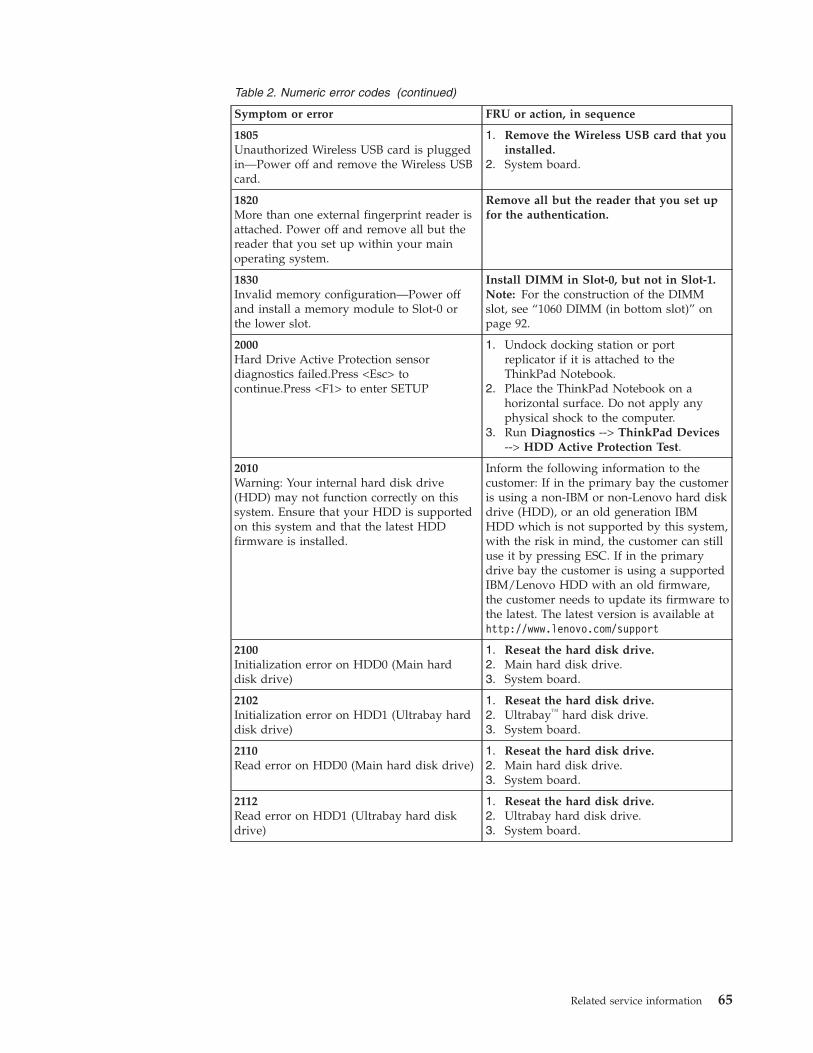
Table 2. Numeric error codes (continued)
Symptom or error FRU or action, in sequence
1805Unauthorized Wireless USB card is pluggedin—Power off and remove the Wireless USBcard.
1. Remove the Wireless USB card that youinstalled.
2. System board.
1820More than one external fingerprint reader isattached. Power off and remove all but thereader that you set up within your mainoperating system.
Remove all but the reader that you set upfor the authentication.
1830Invalid memory configuration—Power offand install a memory module to Slot-0 orthe lower slot.
Install DIMM in Slot-0, but not in Slot-1.Note: For the construction of the DIMMslot, see “1060 DIMM (in bottom slot)” onpage 92.
2000Hard Drive Active Protection sensordiagnostics failed.Press <Esc> tocontinue.Press <F1> to enter SETUP
1. Undock docking station or portreplicator if it is attached to theThinkPad Notebook.
2. Place the ThinkPad Notebook on ahorizontal surface. Do not apply anyphysical shock to the computer.
3. Run Diagnostics --> ThinkPad Devices--> HDD Active Protection Test.
2010Warning: Your internal hard disk drive(HDD) may not function correctly on thissystem. Ensure that your HDD is supportedon this system and that the latest HDDfirmware is installed.
Inform the following information to thecustomer: If in the primary bay the customeris using a non-IBM or non-Lenovo hard diskdrive (HDD), or an old generation IBMHDD which is not supported by this system,with the risk in mind, the customer can stilluse it by pressing ESC. If in the primarydrive bay the customer is using a supportedIBM/Lenovo HDD with an old firmware,the customer needs to update its firmware tothe latest. The latest version is available athttp://www.lenovo.com/support
2100Initialization error on HDD0 (Main harddisk drive)
1. Reseat the hard disk drive.2. Main hard disk drive.3. System board.
2102Initialization error on HDD1 (Ultrabay harddisk drive)
1. Reseat the hard disk drive.2. Ultrabay™ hard disk drive.3. System board.
2110Read error on HDD0 (Main hard disk drive)
1. Reseat the hard disk drive.2. Main hard disk drive.3. System board.
2112Read error on HDD1 (Ultrabay hard diskdrive)
1. Reseat the hard disk drive.2. Ultrabay hard disk drive.3. System board.
Related service information 65
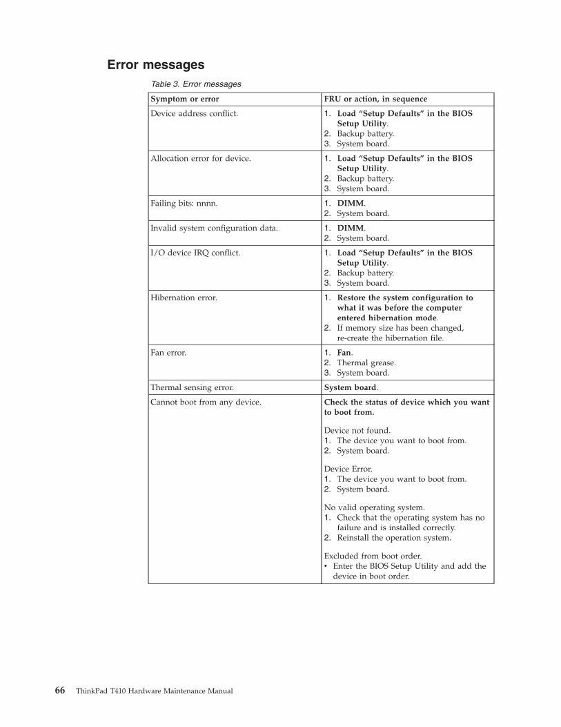
Error messagesTable 3. Error messages
Symptom or error FRU or action, in sequence
Device address conflict. 1. Load “Setup Defaults” in the BIOSSetup Utility.
2. Backup battery.3. System board.
Allocation error for device. 1. Load “Setup Defaults” in the BIOSSetup Utility.
2. Backup battery.3. System board.
Failing bits: nnnn. 1. DIMM.2. System board.
Invalid system configuration data. 1. DIMM.2. System board.
I/O device IRQ conflict. 1. Load “Setup Defaults” in the BIOSSetup Utility.
2. Backup battery.3. System board.
Hibernation error. 1. Restore the system configuration towhat it was before the computerentered hibernation mode.
2. If memory size has been changed,re-create the hibernation file.
Fan error. 1. Fan.2. Thermal grease.3. System board.
Thermal sensing error. System board.
Cannot boot from any device. Check the status of device which you wantto boot from.
Device not found.1. The device you want to boot from.2. System board.
Device Error.1. The device you want to boot from.2. System board.
No valid operating system.1. Check that the operating system has no
failure and is installed correctly.2. Reinstall the operation system.
Excluded from boot order.v Enter the BIOS Setup Utility and add the
device in boot order.
66 ThinkPad T410 Hardware Maintenance Manual
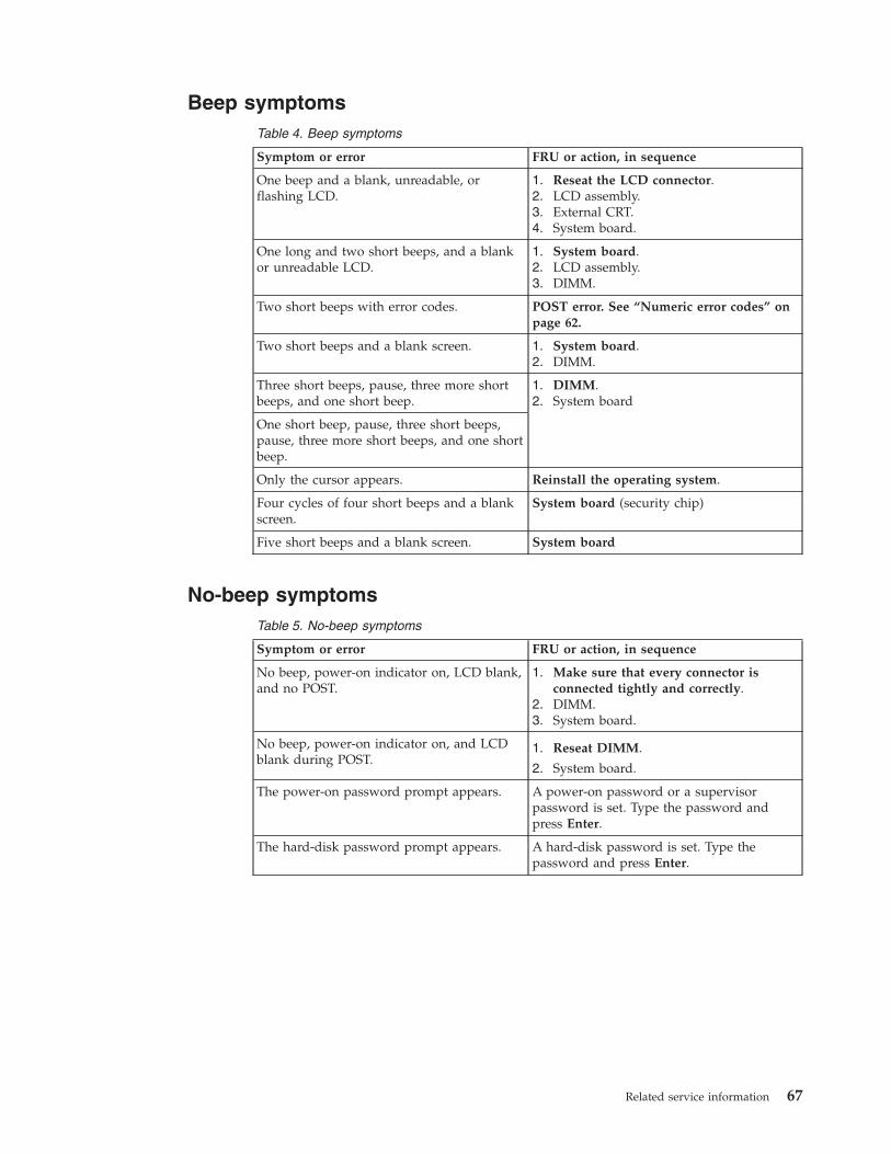
Beep symptomsTable 4. Beep symptoms
Symptom or error FRU or action, in sequence
One beep and a blank, unreadable, orflashing LCD.
1. Reseat the LCD connector.2. LCD assembly.3. External CRT.4. System board.
One long and two short beeps, and a blankor unreadable LCD.
1. System board.2. LCD assembly.3. DIMM.
Two short beeps with error codes. POST error. See “Numeric error codes” onpage 62.
Two short beeps and a blank screen. 1. System board.2. DIMM.
Three short beeps, pause, three more shortbeeps, and one short beep.
1. DIMM.2. System board
One short beep, pause, three short beeps,pause, three more short beeps, and one shortbeep.
Only the cursor appears. Reinstall the operating system.
Four cycles of four short beeps and a blankscreen.
System board (security chip)
Five short beeps and a blank screen. System board
No-beep symptomsTable 5. No-beep symptoms
Symptom or error FRU or action, in sequence
No beep, power-on indicator on, LCD blank,and no POST.
1. Make sure that every connector isconnected tightly and correctly.
2. DIMM.3. System board.
No beep, power-on indicator on, and LCDblank during POST.
1. Reseat DIMM.
2. System board.
The power-on password prompt appears. A power-on password or a supervisorpassword is set. Type the password andpress Enter.
The hard-disk password prompt appears. A hard-disk password is set. Type thepassword and press Enter.
Related service information 67
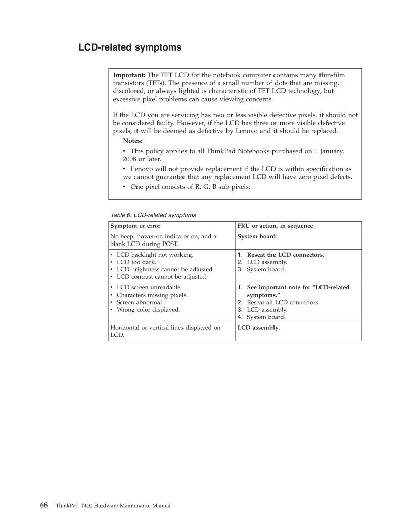
LCD-related symptoms
Table 6. LCD-related symptoms
Symptom or error FRU or action, in sequence
No beep, power-on indicator on, and ablank LCD during POST.
System board.
v LCD backlight not working.v LCD too dark.v LCD brightness cannot be adjusted.v LCD contrast cannot be adjusted.
1. Reseat the LCD connectors.2. LCD assembly.3. System board.
v LCD screen unreadable.v Characters missing pixels.v Screen abnormal.v Wrong color displayed.
1. See important note for “LCD-relatedsymptoms.”
2. Reseat all LCD connectors.3. LCD assembly.4. System board.
Horizontal or vertical lines displayed onLCD.
LCD assembly.
Important: The TFT LCD for the notebook computer contains many thin-filmtransistors (TFTs). The presence of a small number of dots that are missing,discolored, or always lighted is characteristic of TFT LCD technology, butexcessive pixel problems can cause viewing concerns.
If the LCD you are servicing has two or less visible defective pixels, it should notbe considered faulty. However, if the LCD has three or more visible defectivepixels, it will be deemed as defective by Lenovo and it should be replaced.
Notes:
v This policy applies to all ThinkPad Notebooks purchased on 1 January,2008 or later.v Lenovo will not provide replacement if the LCD is within specification aswe cannot guarantee that any replacement LCD will have zero pixel defects.v One pixel consists of R, G, B sub-pixels.
68 ThinkPad T410 Hardware Maintenance Manual
Intermittent problemsIntermittent system hang problems can be due to a variety of causes that havenothing to do with a hardware defect, such as cosmic radiation, electrostaticdischarge, or software errors. FRU replacement should be considered only when aproblem recurs.
When analyzing an intermittent problem, do the following:1. Run the diagnostic test for the system board in loop mode at least 10 times.2. If no error is detected, do not replace any FRUs.3. If any error is detected, replace the FRU shown by the FRU code. Rerun the
test to verify that no more errors exist.
Undetermined problemsIf the diagnostic tests did not identify the adapter or device that has failed, ifwrong devices are installed, or if the system simply is not operating, follow theseprocedures to isolate the failing FRU (do not isolate FRUs that have no defects).
Verify that all attached devices are supported by the computer.
Verify that the power supply being used at the time of the failure is operatingcorrectly. (See “Power system checkout” on page 51.)1. Turn off the computer.2. Visually check each FRU for damage. Replace any damaged FRU.3. Remove or disconnect all of the following devices:
a. Non-ThinkPad devicesb. Devices attached to the docking station or the port replicatorc. Printer, mouse, and other external devicesd. Battery packe. Hard disk drivef. External diskette drive or optical driveg. DIMMh. Optical disk or diskette in the internal drivei. PC Cards
4. Turn on the computer.5. Determine whether the problem has been solved.6. If the problem does not recur, reconnect the removed devices one at a time
until you find the failing FRU.7. If the problem remains, replace the following FRUs one at a time (do not
replace a nondefective FRU):a. System boardb. LCD assembly
Related service information 69

70 ThinkPad T410 Hardware Maintenance Manual
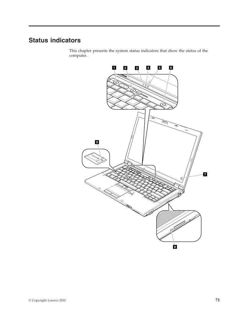
Status indicators
This chapter presents the system status indicators that show the status of thecomputer.
7
1 2 3 4 5 6
8
9
© Copyright Lenovo 2010 71
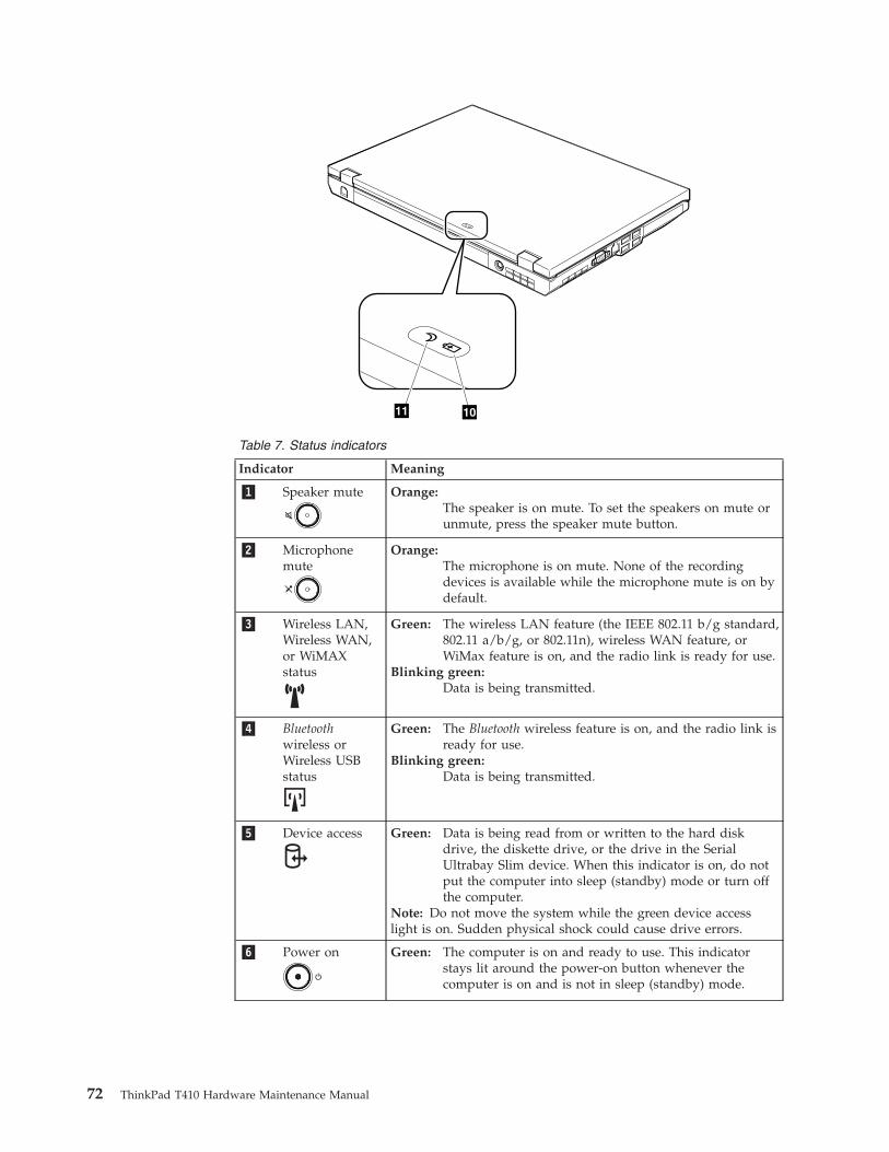
11 10
Table 7. Status indicators
Indicator Meaning
�1� Speaker mute Orange:The speaker is on mute. To set the speakers on mute orunmute, press the speaker mute button.
�2� Microphonemute
Orange:The microphone is on mute. None of the recordingdevices is available while the microphone mute is on bydefault.
�3� Wireless LAN,Wireless WAN,or WiMAXstatus
Green: The wireless LAN feature (the IEEE 802.11 b/g standard,802.11 a/b/g, or 802.11n), wireless WAN feature, orWiMax feature is on, and the radio link is ready for use.
Blinking green:Data is being transmitted.
�4� Bluetoothwireless orWireless USBstatus
Green: The Bluetooth wireless feature is on, and the radio link isready for use.
Blinking green:Data is being transmitted.
�5� Device access Green: Data is being read from or written to the hard diskdrive, the diskette drive, or the drive in the SerialUltrabay Slim device. When this indicator is on, do notput the computer into sleep (standby) mode or turn offthe computer.
Note: Do not move the system while the green device accesslight is on. Sudden physical shock could cause drive errors.
�6� Power on Green: The computer is on and ready to use. This indicatorstays lit around the power-on button whenever thecomputer is on and is not in sleep (standby) mode.
72 ThinkPad T410 Hardware Maintenance Manual
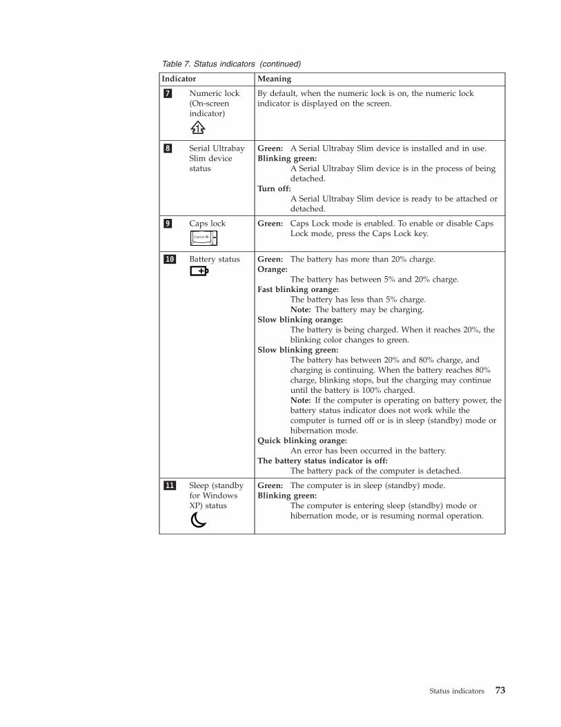
Table 7. Status indicators (continued)
Indicator Meaning
�7� Numeric lock(On-screenindicator)
By default, when the numeric lock is on, the numeric lockindicator is displayed on the screen.
�8� Serial UltrabaySlim devicestatus
Green: A Serial Ultrabay Slim device is installed and in use.Blinking green:
A Serial Ultrabay Slim device is in the process of beingdetached.
Turn off:A Serial Ultrabay Slim device is ready to be attached ordetached.
�9� Caps lock Green: Caps Lock mode is enabled. To enable or disable CapsLock mode, press the Caps Lock key.
�10� Battery status Green: The battery has more than 20% charge.Orange:
The battery has between 5% and 20% charge.Fast blinking orange:
The battery has less than 5% charge.Note: The battery may be charging.
Slow blinking orange:The battery is being charged. When it reaches 20%, theblinking color changes to green.
Slow blinking green:The battery has between 20% and 80% charge, andcharging is continuing. When the battery reaches 80%charge, blinking stops, but the charging may continueuntil the battery is 100% charged.Note: If the computer is operating on battery power, thebattery status indicator does not work while thecomputer is turned off or is in sleep (standby) mode orhibernation mode.
Quick blinking orange:An error has been occurred in the battery.
The battery status indicator is off:The battery pack of the computer is detached.
�11� Sleep (standbyfor WindowsXP) status
Green: The computer is in sleep (standby) mode.Blinking green:
The computer is entering sleep (standby) mode orhibernation mode, or is resuming normal operation.
Status indicators 73

74 ThinkPad T410 Hardware Maintenance Manual
Fn key combinations
The following table shows the function of each combination of Fn with a functionkey.
Table 8. Fn key combinations
Key combination Description
Fn+F1 Reserved.
Fn+F2 Lock the computer.
Fn+F3 Select a power plan (in Windows XP, power scheme) that has beencreated by Power Manager, or adjust the power level by using theslider control. When you press this combination, a panel for selecting apower plan (power scheme) appears.
Notes:
To use this combination of the keys, ThinkPad PM device drivermust have been installed on the computer.
If you have logged on with an administrator user ID in WindowsXP, and you press Fn+F3, the panel for selecting a power schemeappears. If you have logged on with another user ID in WindowsXP, and you press Fn+F3, the panel does not appear.
Fn+F4 Put the computer in sleep (standby) mode. To return to normaloperation, press the Fn key only, without pressing a function key.
Notes:
To use this combination of the keys, ThinkPad PM device drivermust have been installed on the computer.
If you want to use the combination to put the computer intohibernation mode or do-nothing mode (in Windows XP, shut thecomputer down or show the panel for turning off the computer),change the settings in the Power Manager.
Fn+F5 Enable or disable the built-in wireless networking features. If you pressFn+F5, a list of wireless features is displayed. You can quickly changethe power state of each feature in the list.Note: If you want to use Fn+F5 to enable or disable the wirelessfeatures, the following device drivers must be installed on thecomputer beforehand:v Power Management driverv OnScreen Display Utilityv Wireless device drivers
Fn+F6 Change the camera and audio settings. When you press Fn+F6, thecamera and audio setting window is opened and the camera preview isturned on.Note: The camera settings area only appears if the computer has anintegrated camera.
© Copyright Lenovo 2010 75
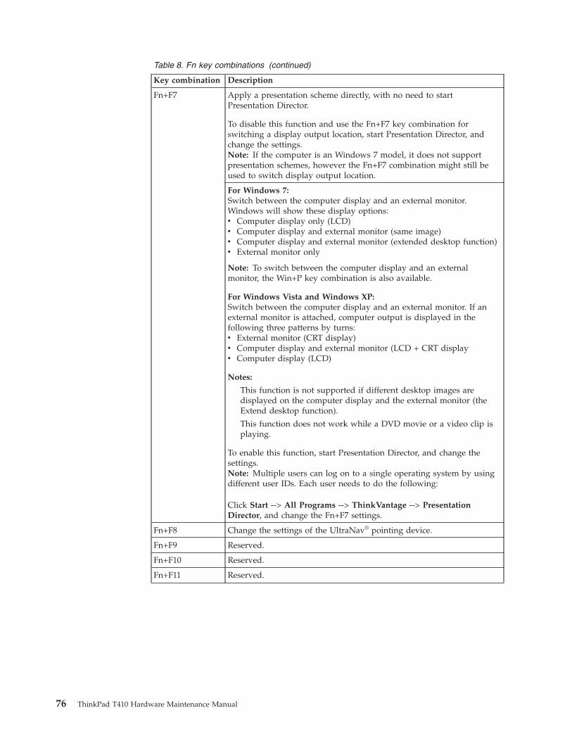
Table 8. Fn key combinations (continued)
Key combination Description
Fn+F7 Apply a presentation scheme directly, with no need to startPresentation Director.
To disable this function and use the Fn+F7 key combination forswitching a display output location, start Presentation Director, andchange the settings.Note: If the computer is an Windows 7 model, it does not supportpresentation schemes, however the Fn+F7 combination might still beused to switch display output location.
For Windows 7:Switch between the computer display and an external monitor.Windows will show these display options:v Computer display only (LCD)v Computer display and external monitor (same image)v Computer display and external monitor (extended desktop function)v External monitor only
Note: To switch between the computer display and an externalmonitor, the Win+P key combination is also available.
For Windows Vista and Windows XP:Switch between the computer display and an external monitor. If anexternal monitor is attached, computer output is displayed in thefollowing three patterns by turns:v External monitor (CRT display)v Computer display and external monitor (LCD + CRT displayv Computer display (LCD)
Notes:
This function is not supported if different desktop images aredisplayed on the computer display and the external monitor (theExtend desktop function).
This function does not work while a DVD movie or a video clip isplaying.
To enable this function, start Presentation Director, and change thesettings.Note: Multiple users can log on to a single operating system by usingdifferent user IDs. Each user needs to do the following:
Click Start --> All Programs --> ThinkVantage --> PresentationDirector, and change the Fn+F7 settings.
Fn+F8 Change the settings of the UltraNav® pointing device.
Fn+F9 Reserved.
Fn+F10 Reserved.
Fn+F11 Reserved.
76 ThinkPad T410 Hardware Maintenance Manual
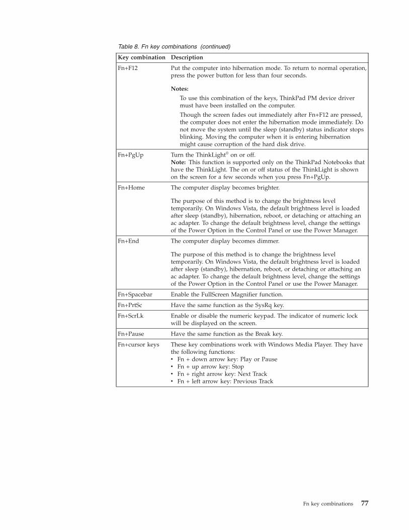
Table 8. Fn key combinations (continued)
Key combination Description
Fn+F12 Put the computer into hibernation mode. To return to normal operation,press the power button for less than four seconds.
Notes:
To use this combination of the keys, ThinkPad PM device drivermust have been installed on the computer.
Though the screen fades out immediately after Fn+F12 are pressed,the computer does not enter the hibernation mode immediately. Donot move the system until the sleep (standby) status indicator stopsblinking. Moving the computer when it is entering hibernationmight cause corruption of the hard disk drive.
Fn+PgUp Turn the ThinkLight® on or off.Note: This function is supported only on the ThinkPad Notebooks thathave the ThinkLight. The on or off status of the ThinkLight is shownon the screen for a few seconds when you press Fn+PgUp.
Fn+Home The computer display becomes brighter.
The purpose of this method is to change the brightness leveltemporarily. On Windows Vista, the default brightness level is loadedafter sleep (standby), hibernation, reboot, or detaching or attaching anac adapter. To change the default brightness level, change the settingsof the Power Option in the Control Panel or use the Power Manager.
Fn+End The computer display becomes dimmer.
The purpose of this method is to change the brightness leveltemporarily. On Windows Vista, the default brightness level is loadedafter sleep (standby), hibernation, reboot, or detaching or attaching anac adapter. To change the default brightness level, change the settingsof the Power Option in the Control Panel or use the Power Manager.
Fn+Spacebar Enable the FullScreen Magnifier function.
Fn+PrtSc Have the same function as the SysRq key.
Fn+ScrLk Enable or disable the numeric keypad. The indicator of numeric lockwill be displayed on the screen.
Fn+Pause Have the same function as the Break key.
Fn+cursor keys These key combinations work with Windows Media Player. They havethe following functions:v Fn + down arrow key: Play or Pausev Fn + up arrow key: Stopv Fn + right arrow key: Next Trackv Fn + left arrow key: Previous Track
Fn key combinations 77

78 ThinkPad T410 Hardware Maintenance Manual
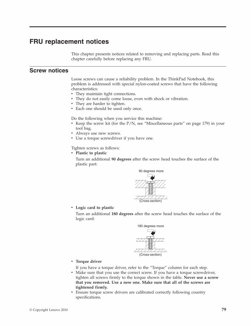
FRU replacement notices
This chapter presents notices related to removing and replacing parts. Read thischapter carefully before replacing any FRU.
Screw noticesLoose screws can cause a reliability problem. In the ThinkPad Notebook, thisproblem is addressed with special nylon-coated screws that have the followingcharacteristics:v They maintain tight connections.v They do not easily come loose, even with shock or vibration.v They are harder to tighten.v Each one should be used only once.
Do the following when you service this machine:v Keep the screw kit (for the P/N, see “Miscellaneous parts” on page 179) in your
tool bag.v Always use new screws.v Use a torque screwdriver if you have one.
Tighten screws as follows:v Plastic to plastic
Turn an additional 90 degrees after the screw head touches the surface of theplastic part:
90 degrees more
(Cross-section)
v Logic card to plastic
Turn an additional 180 degrees after the screw head touches the surface of thelogic card:
180 degrees more
(Cross-section)
v Torque driver
If you have a torque driver, refer to the “Torque” column for each step.v Make sure that you use the correct screw. If you have a torque screwdriver,
tighten all screws firmly to the torque shown in the table. Never use a screwthat you removed. Use a new one. Make sure that all of the screws aretightened firmly.
v Ensure torque screw drivers are calibrated correctly following countryspecifications.
© Copyright Lenovo 2010 79
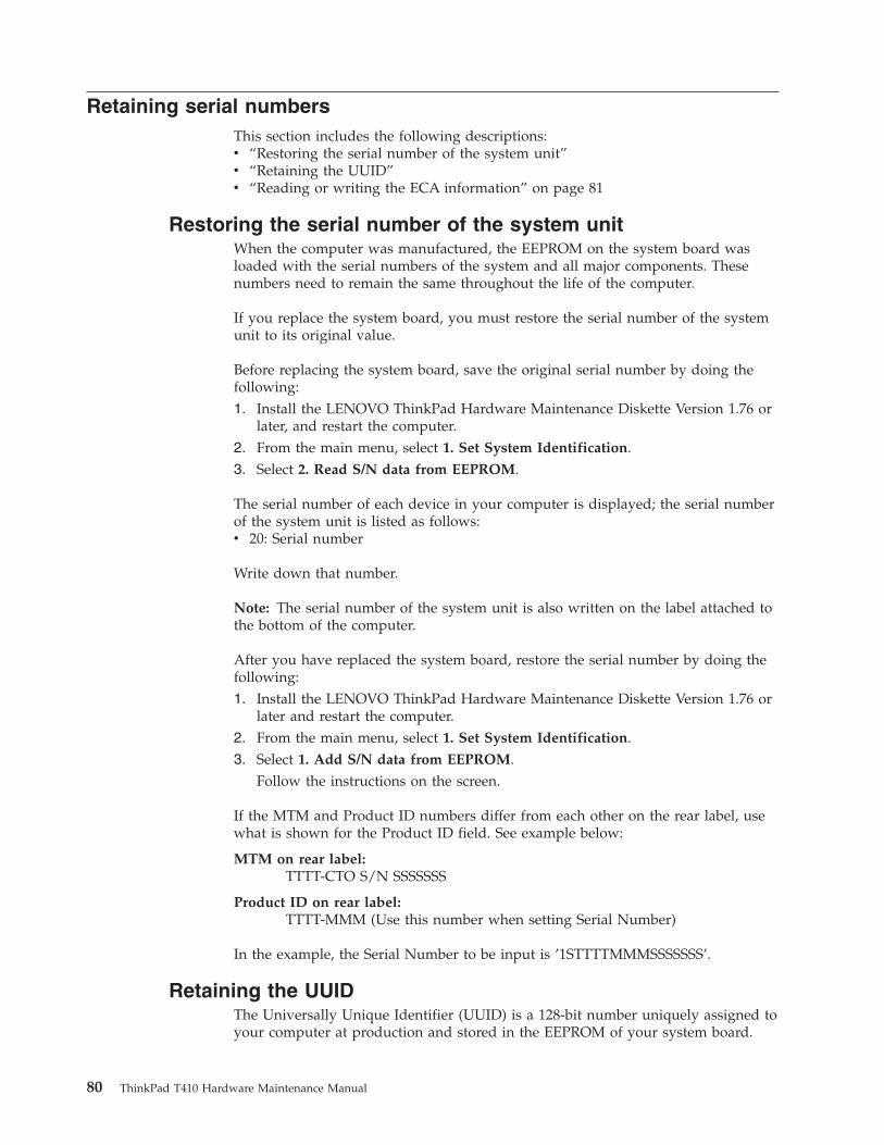
Retaining serial numbersThis section includes the following descriptions:v “Restoring the serial number of the system unit”v “Retaining the UUID”v “Reading or writing the ECA information” on page 81
Restoring the serial number of the system unitWhen the computer was manufactured, the EEPROM on the system board wasloaded with the serial numbers of the system and all major components. Thesenumbers need to remain the same throughout the life of the computer.
If you replace the system board, you must restore the serial number of the systemunit to its original value.
Before replacing the system board, save the original serial number by doing thefollowing:1. Install the LENOVO ThinkPad Hardware Maintenance Diskette Version 1.76 or
later, and restart the computer.2. From the main menu, select 1. Set System Identification.3. Select 2. Read S/N data from EEPROM.
The serial number of each device in your computer is displayed; the serial numberof the system unit is listed as follows:v 20: Serial number
Write down that number.
Note: The serial number of the system unit is also written on the label attached tothe bottom of the computer.
After you have replaced the system board, restore the serial number by doing thefollowing:1. Install the LENOVO ThinkPad Hardware Maintenance Diskette Version 1.76 or
later and restart the computer.2. From the main menu, select 1. Set System Identification.3. Select 1. Add S/N data from EEPROM.
Follow the instructions on the screen.
If the MTM and Product ID numbers differ from each other on the rear label, usewhat is shown for the Product ID field. See example below:
MTM on rear label:TTTT-CTO S/N SSSSSSS
Product ID on rear label:TTTT-MMM (Use this number when setting Serial Number)
In the example, the Serial Number to be input is ’1STTTTMMMSSSSSSS’.
Retaining the UUIDThe Universally Unique Identifier (UUID) is a 128-bit number uniquely assigned toyour computer at production and stored in the EEPROM of your system board.
80 ThinkPad T410 Hardware Maintenance Manual
The algorithm that generates the number is designed to provide unique IDs untilthe year A.D. 3400. No two computers in the world have the same number.
When you replace the system board, you must set the UUID on the new systemboard as follows:1. Install the LENOVO ThinkPad Hardware Maintenance Diskette Version 1.76 or
later, and restart the computer.2. From the main menu, select 4. Assign UUID.
A new UUID is created and written. If a valid UUID already exists, it is notoverwritten.
Reading or writing the ECA informationInformation on Engineering Change Announcements (ECA) are stored in theEEPROM of the system board. The electronic storage of this information simplifiesthe procedure to check if the ECA has been previously applied to a machine. Themachine does not need to be disassembled to check for the ECA application.
To check what ECAs have been previously applied to the machine, use the ECAInformation Read/Write function on the LENOVO ThinkPad HardwareMaintenance Diskette Version 1.76 or later.1. Insert the LENOVO ThinkPad Hardware Maintenance Diskette Version 1.76 or
later, and restart the computer.2. From the main menu, select 6. Set ECA Information.3. To read ECA information, select 2. Read ECA/rework number from EEPROM
and follow the instruction.4. To read box build date, select 5. Read box build date from EEPROM, and
follow the instruction on the screen.
After an ECA has been applied to the machine, the EEPROM must be updated toreflect the ECA’s application. Use the LENOVO ThinkPad Hardware MaintenanceDiskette Version 1.76 or later to update the EEPROM.
Note: Only the ECA number is stored in the EEPROM. The machine type of theECA is assumed be the same as the machine type of the machine that had the ECAapplied to it.1. Insert the LENOVO ThinkPad Hardware Maintenance Diskette Version 1.76 or
later, and restart the computer.2. From the main menu, select 6. Set ECA Information.3. To write ECA information, select 1. Write ECA/rework number from EEPROM,
and follow the instruction.4. To write box build date, select 4. Write box build date from EEPROM, and
follow the instruction on the screen.
If the system board is being replaced, try to read the ECA information from the oldsystem board and transfer the information to the new system. If the system boardis inoperable, this will not be possible.
FRU replacement notices 81

82 ThinkPad T410 Hardware Maintenance Manual
Removing and replacing a FRU
This chapter presents directions and drawings for use in removing and replacing aFRU. Be sure to observe the following general rules:1. Do not try to service any computer unless you have been trained and certified.
An untrained person runs the risk of damaging parts.2. Before replacing any FRU, review “FRU replacement notices” on page 79.3. Begin by removing any FRUs that have to be removed before the failing FRU.
Any such FRUs are listed at the top of the page. Remove them in the order inwhich they are listed.
4. Follow the correct sequence in the steps for removing the FRU, as given in thedrawings by the numbers in square callouts.
5. When turning a screw to replace a FRU, turn it in the direction as given by thearrow in the drawing.
6. When removing the FRU, move it in the direction as given by the arrow in thedrawing.
7. To put the new FRU in place, reverse the removal procedure and follow anynotes that pertain to replacement. For information about connecting andarranging internal cables, see “Locations” on page 149.
8. When replacing a FRU, use the correct screw as shown in the procedures.
DANGER
Before removing any FRU, turn off the computer, unplug all power cordsfrom electrical outlets, remove the battery pack, and then disconnect anyinterconnecting cables.
Attention: After replacing a FRU, do not turn on the computer until you havemade sure that all screws, springs, and other small parts are in place and none areloose inside the computer. Verify this by shaking the computer gently and listeningfor rattling sounds. Metallic parts or metal flakes can cause electrical short circuits.
Attention: The system board is sensitive to, and can be damaged by, electrostaticdischarge. Before touching it, establish personal grounding by touching a groundpoint with one hand or by using an electrostatic discharge (ESD) strap (P/N6405959).
© Copyright Lenovo 2010 83
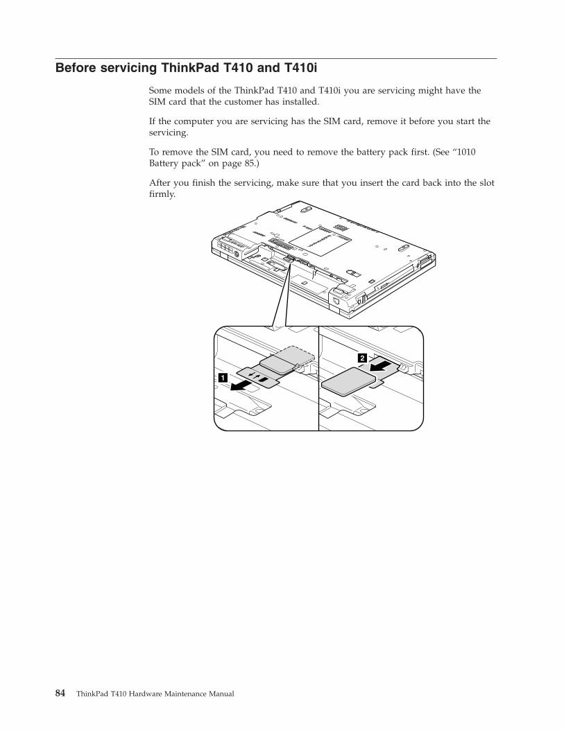
Before servicing ThinkPad T410 and T410i
Some models of the ThinkPad T410 and T410i you are servicing might have theSIM card that the customer has installed.
If the computer you are servicing has the SIM card, remove it before you start theservicing.
To remove the SIM card, you need to remove the battery pack first. (See “1010Battery pack” on page 85.)
After you finish the servicing, make sure that you insert the card back into the slotfirmly.
1
2
84 ThinkPad T410 Hardware Maintenance Manual
1010 Battery pack
Table 9. Removal steps of battery pack
DANGER
Use only the battery specified in the parts list for your computer. Any otherbattery could ignite or explode.
Important notice for replacing a battery pack:ThinkVantage Toolbox (in Windows 7) and Lenovo System Toolbox (in WindowsVista and Windows XP) have an automatic battery diagnostic that determines ifthe battery pack is defective. A battery pack FRU should not be replaced unlessthis diagnostic shows that the battery is defective.
The only exception to this is if the battery pack is physically damaged or acustomer is reporting a possible safety issue.
If ThinkVantage Toolbox or Lenovo System Toolbox is not installed in thecomputer, the customer should download this program before a non-physicallydamaged battery pack is replaced. Note that a physically damaged battery packis non-warranty replacement.
Removing and replacing a FRU 85
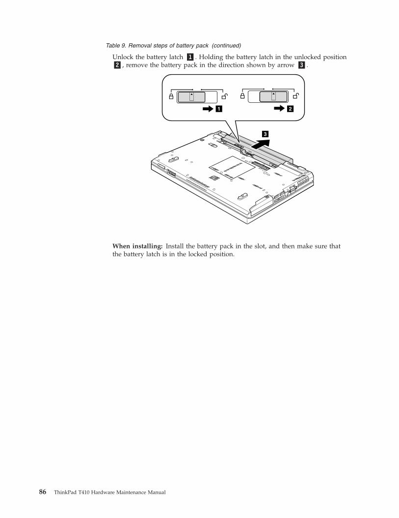
Table 9. Removal steps of battery pack (continued)
Unlock the battery latch �1�. Holding the battery latch in the unlocked position�2�, remove the battery pack in the direction shown by arrow �3�.
3
21
When installing: Install the battery pack in the slot, and then make sure thatthe battery latch is in the locked position.
86 ThinkPad T410 Hardware Maintenance Manual
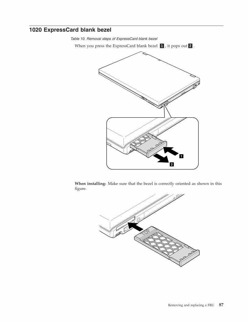
1020 ExpressCard blank bezelTable 10. Removal steps of ExpressCard blank bezel
When you press the ExpressCard blank bezel �1�, it pops out�2�.
1
2
When installing: Make sure that the bezel is correctly oriented as shown in thisfigure.
Removing and replacing a FRU 87
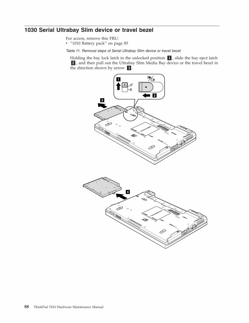
1030 Serial Ultrabay Slim device or travel bezelFor access, remove this FRU:v “1010 Battery pack” on page 85
Table 11. Removal steps of Serial Ultrabay Slim device or travel bezel
Holding the bay lock latch in the unlocked position �1�, slide the bay eject latch�2�, and then pull out the Ultrabay Slim Media Bay device or the travel bezel inthe direction shown by arrow �3�.
32
1
4
88 ThinkPad T410 Hardware Maintenance Manual
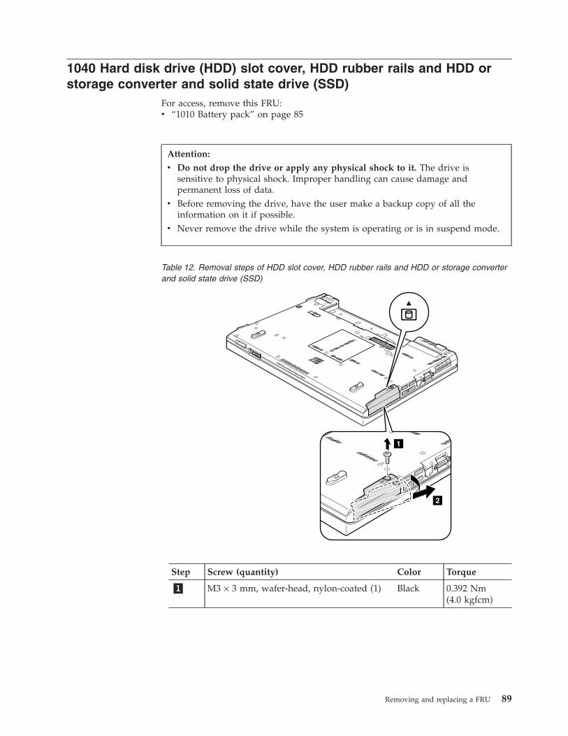
1040 Hard disk drive (HDD) slot cover, HDD rubber rails and HDD orstorage converter and solid state drive (SSD)
For access, remove this FRU:v “1010 Battery pack” on page 85
Table 12. Removal steps of HDD slot cover, HDD rubber rails and HDD or storage converterand solid state drive (SSD)
2
1
Step Screw (quantity) Color Torque
�1� M3 × 3 mm, wafer-head, nylon-coated (1) Black 0.392 Nm(4.0 kgfcm)
Attention:
v Do not drop the drive or apply any physical shock to it. The drive issensitive to physical shock. Improper handling can cause damage andpermanent loss of data.
v Before removing the drive, have the user make a backup copy of all theinformation on it if possible.
v Never remove the drive while the system is operating or is in suspend mode.
Removing and replacing a FRU 89
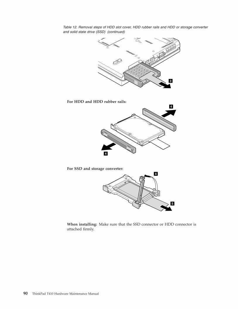
Table 12. Removal steps of HDD slot cover, HDD rubber rails and HDD or storage converterand solid state drive (SSD) (continued)
3
For HDD and HDD rubber rails:4
4
For SSD and storage converter:
5
4
When installing: Make sure that the SSD connector or HDD connector isattached firmly.
90 ThinkPad T410 Hardware Maintenance Manual
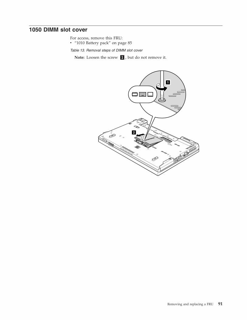
1050 DIMM slot coverFor access, remove this FRU:v “1010 Battery pack” on page 85
Table 13. Removal steps of DIMM slot cover
Note: Loosen the screw �1�, but do not remove it.
1
2
Removing and replacing a FRU 91
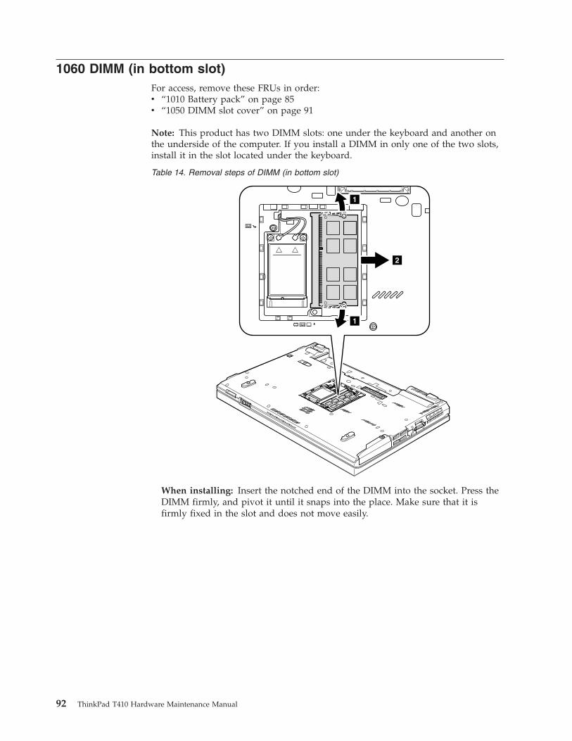
1060 DIMM (in bottom slot)For access, remove these FRUs in order:v “1010 Battery pack” on page 85v “1050 DIMM slot cover” on page 91
Note: This product has two DIMM slots: one under the keyboard and another onthe underside of the computer. If you install a DIMM in only one of the two slots,install it in the slot located under the keyboard.
Table 14. Removal steps of DIMM (in bottom slot)
1
1
2
When installing: Insert the notched end of the DIMM into the socket. Press theDIMM firmly, and pivot it until it snaps into the place. Make sure that it isfirmly fixed in the slot and does not move easily.
92 ThinkPad T410 Hardware Maintenance Manual
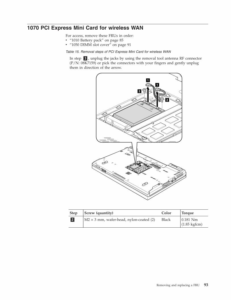
1070 PCI Express Mini Card for wireless WANFor access, remove these FRUs in order:v “1010 Battery pack” on page 85v “1050 DIMM slot cover” on page 91
Table 15. Removal steps of PCI Express Mini Card for wireless WAN
In step �3�, unplug the jacks by using the removal tool antenna RF connector(P/N: 08K7159) or pick the connectors with your fingers and gently unplugthem in direction of the arrow.
2
1
1
2
Step Screw (quantity) Color Torque
�2� M2 × 3 mm, wafer-head, nylon-coated (2) Black 0.181 Nm(1.85 kgfcm)
Removing and replacing a FRU 93
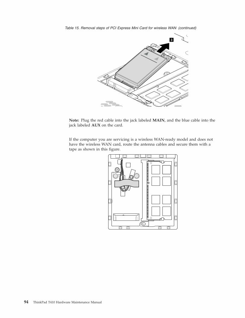
Table 15. Removal steps of PCI Express Mini Card for wireless WAN (continued)
3
Note: Plug the red cable into the jack labeled MAIN, and the blue cable into thejack labeled AUX on the card.
If the computer you are servicing is a wireless WAN-ready model and does nothave the wireless WAN card, route the antenna cables and secure them with atape as shown in this figure.
94 ThinkPad T410 Hardware Maintenance Manual
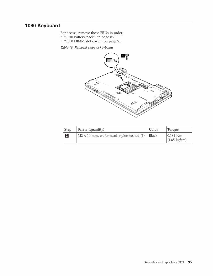
1080 KeyboardFor access, remove these FRUs in order:v “1010 Battery pack” on page 85v “1050 DIMM slot cover” on page 91
Table 16. Removal steps of keyboard
1
Step Screw (quantity) Color Torque
�1� M2 × 10 mm, wafer-head, nylon-coated (1) Black 0.181 Nm(1.85 kgfcm)
Removing and replacing a FRU 95
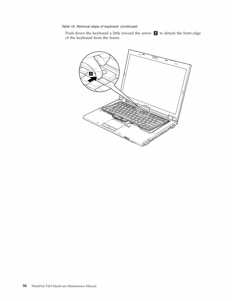
Table 16. Removal steps of keyboard (continued)
Push down the keyboard a little toward the arrow �2� to detach the front edgeof the keyboard from the frame.
2
96 ThinkPad T410 Hardware Maintenance Manual
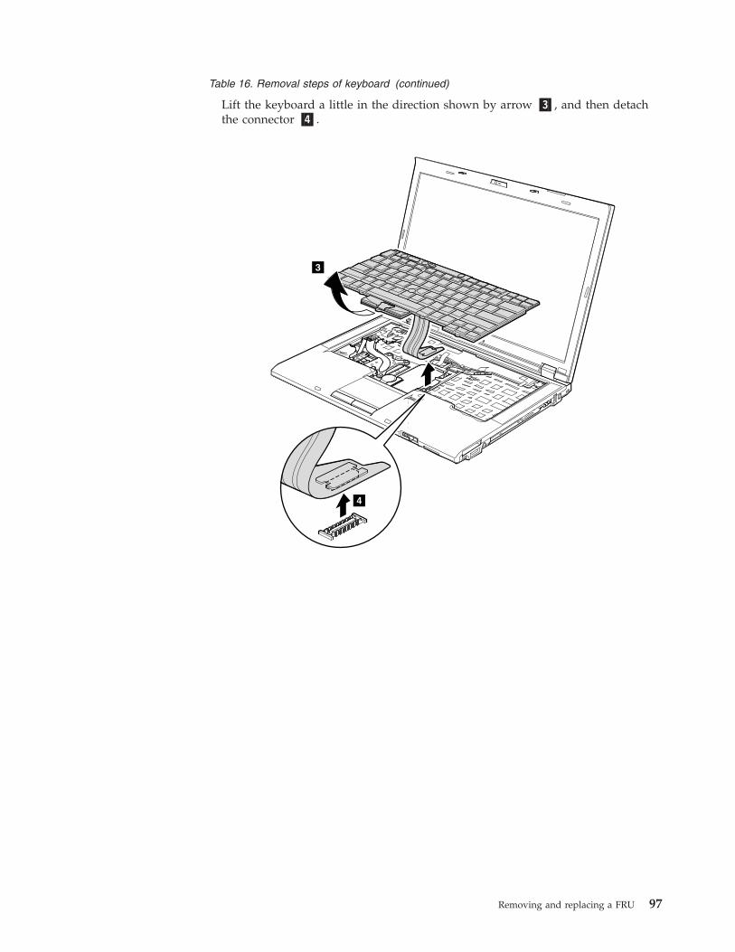
Table 16. Removal steps of keyboard (continued)
Lift the keyboard a little in the direction shown by arrow �3�, and then detachthe connector �4�.
4
3
Removing and replacing a FRU 97
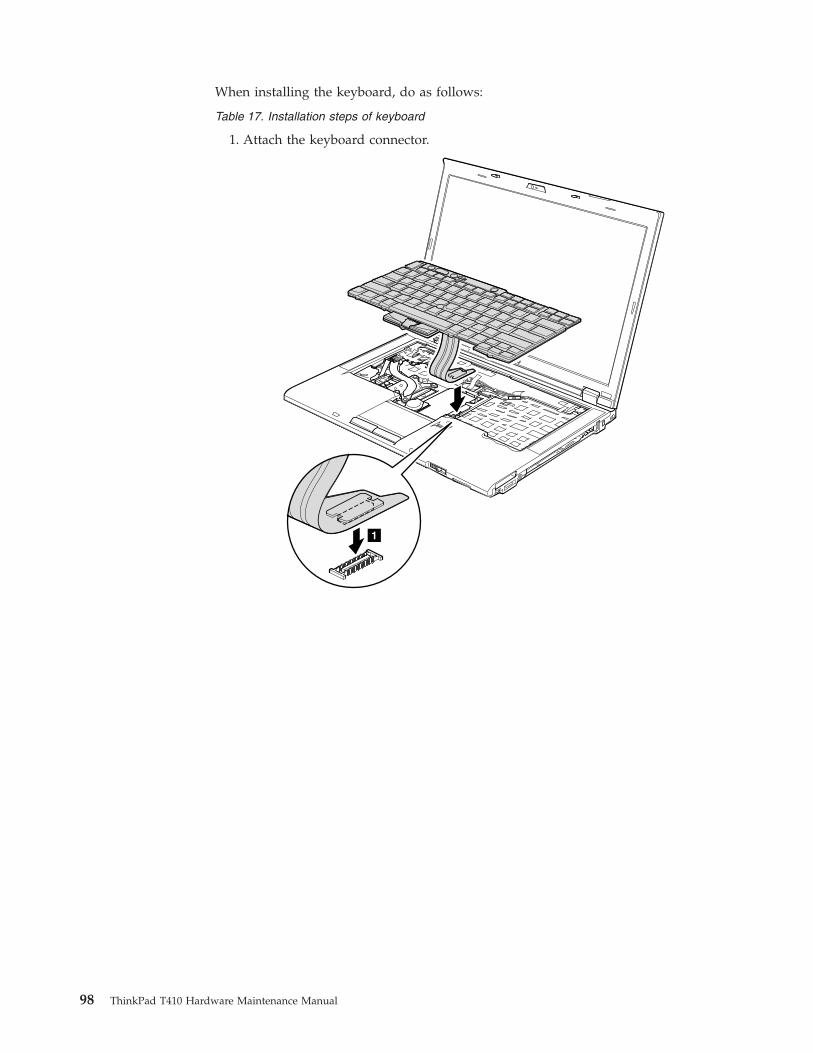
When installing the keyboard, do as follows:
Table 17. Installation steps of keyboard
1. Attach the keyboard connector.
1
98 ThinkPad T410 Hardware Maintenance Manual
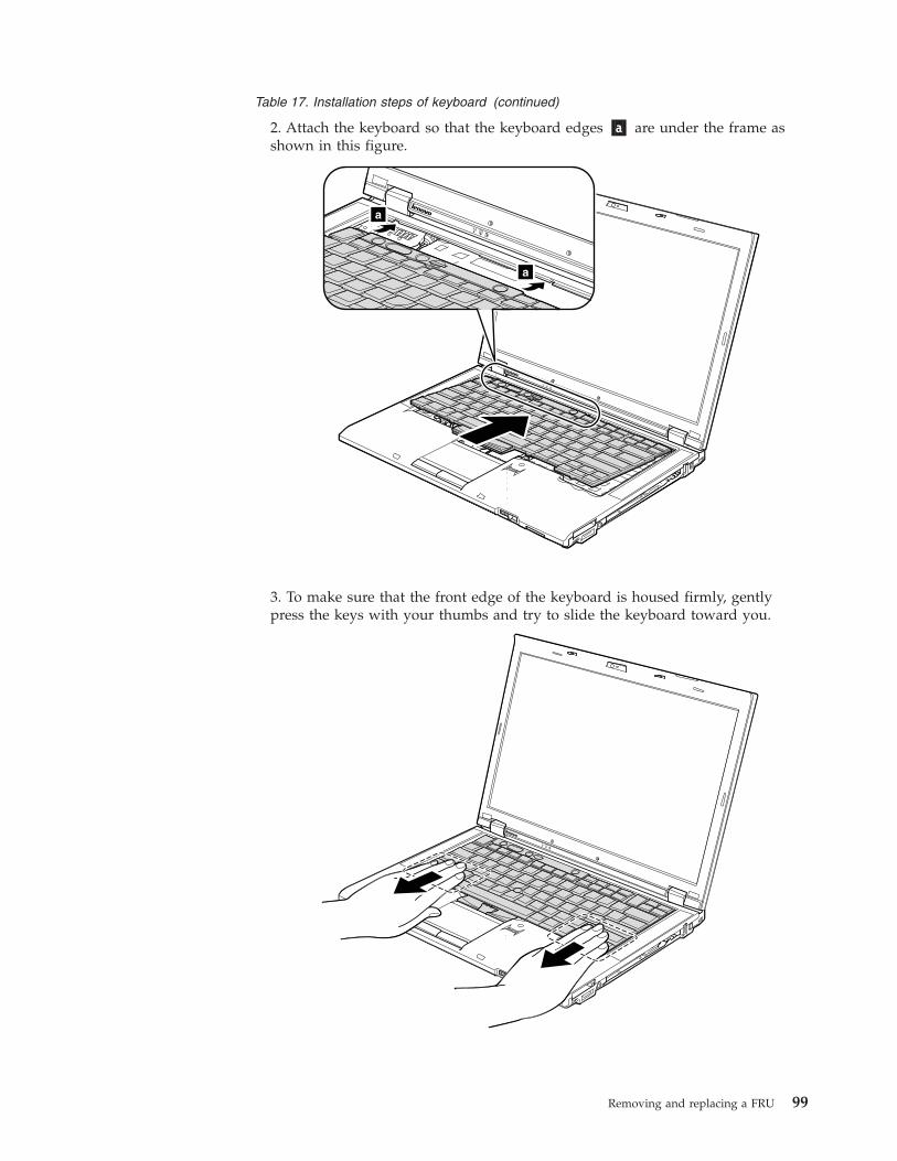
Table 17. Installation steps of keyboard (continued)
2. Attach the keyboard so that the keyboard edges �a� are under the frame asshown in this figure.
a
a
3. To make sure that the front edge of the keyboard is housed firmly, gentlypress the keys with your thumbs and try to slide the keyboard toward you.
Removing and replacing a FRU 99
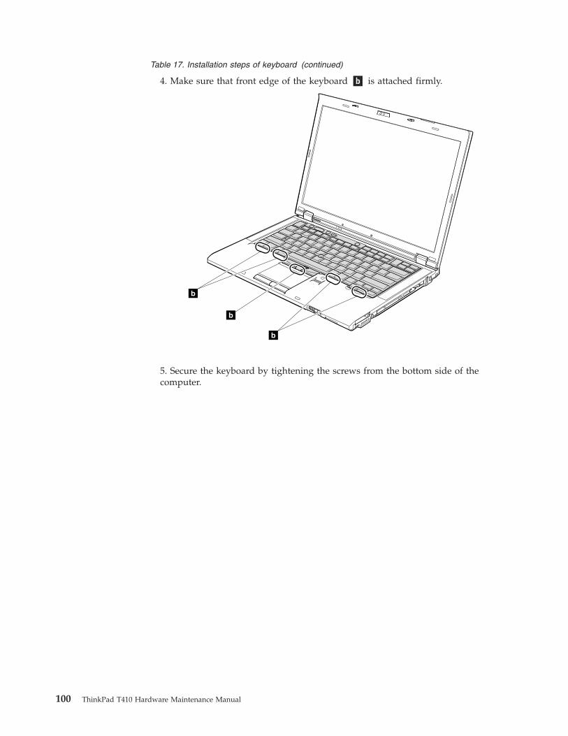
Table 17. Installation steps of keyboard (continued)
4. Make sure that front edge of the keyboard �b� is attached firmly.
b
b
b
5. Secure the keyboard by tightening the screws from the bottom side of thecomputer.
100 ThinkPad T410 Hardware Maintenance Manual
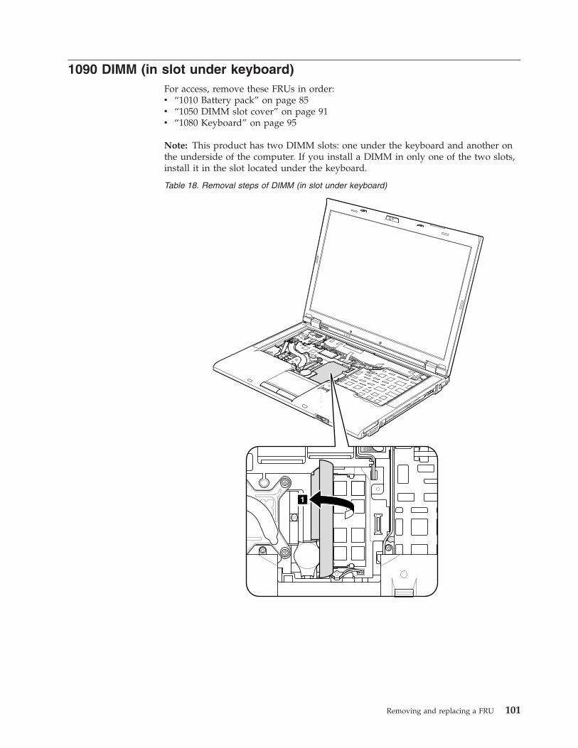
1090 DIMM (in slot under keyboard)For access, remove these FRUs in order:v “1010 Battery pack” on page 85v “1050 DIMM slot cover” on page 91v “1080 Keyboard” on page 95
Note: This product has two DIMM slots: one under the keyboard and another onthe underside of the computer. If you install a DIMM in only one of the two slots,install it in the slot located under the keyboard.
Table 18. Removal steps of DIMM (in slot under keyboard)
1
Removing and replacing a FRU 101
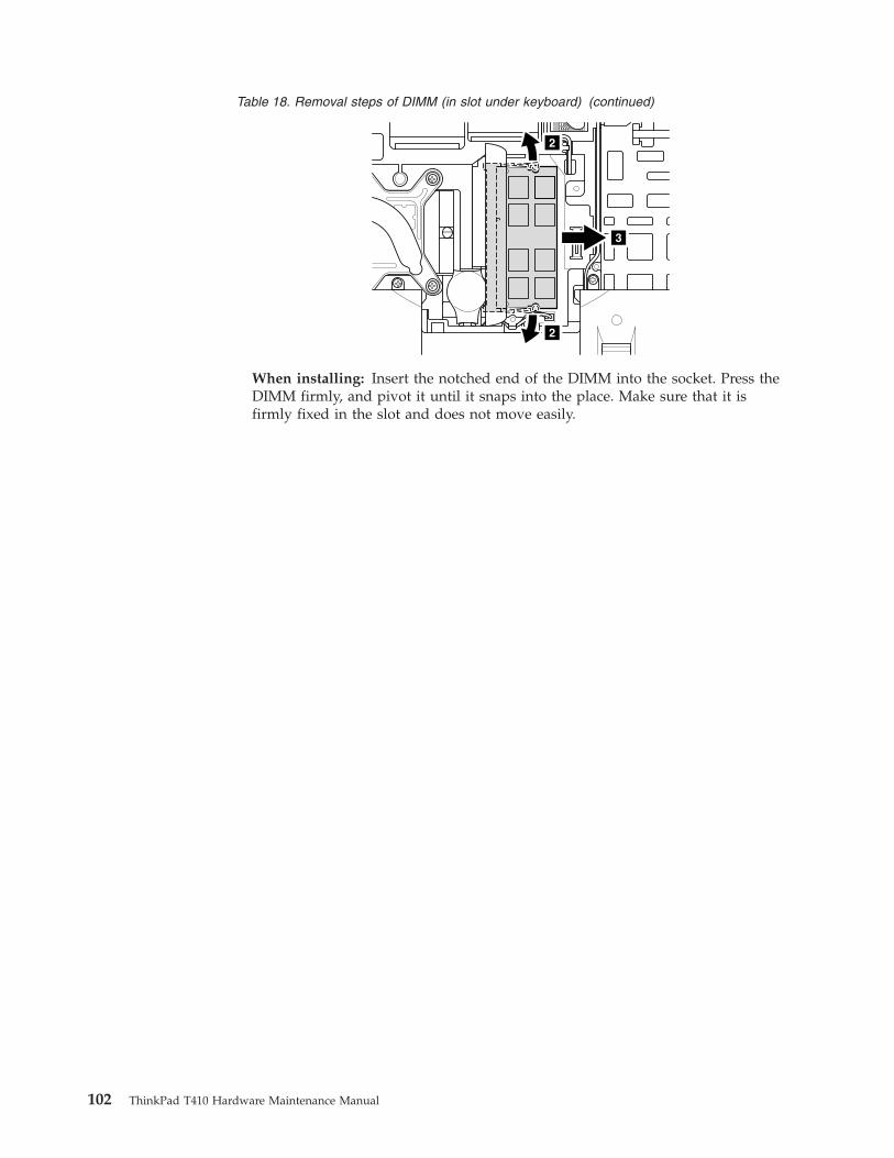
Table 18. Removal steps of DIMM (in slot under keyboard) (continued)
2
2
3
When installing: Insert the notched end of the DIMM into the socket. Press theDIMM firmly, and pivot it until it snaps into the place. Make sure that it isfirmly fixed in the slot and does not move easily.
102 ThinkPad T410 Hardware Maintenance Manual
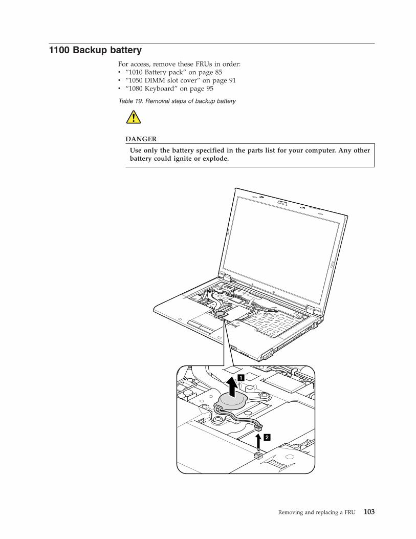
1100 Backup batteryFor access, remove these FRUs in order:v “1010 Battery pack” on page 85v “1050 DIMM slot cover” on page 91v “1080 Keyboard” on page 95
Table 19. Removal steps of backup battery
DANGER
Use only the battery specified in the parts list for your computer. Any otherbattery could ignite or explode.
2
1
Removing and replacing a FRU 103
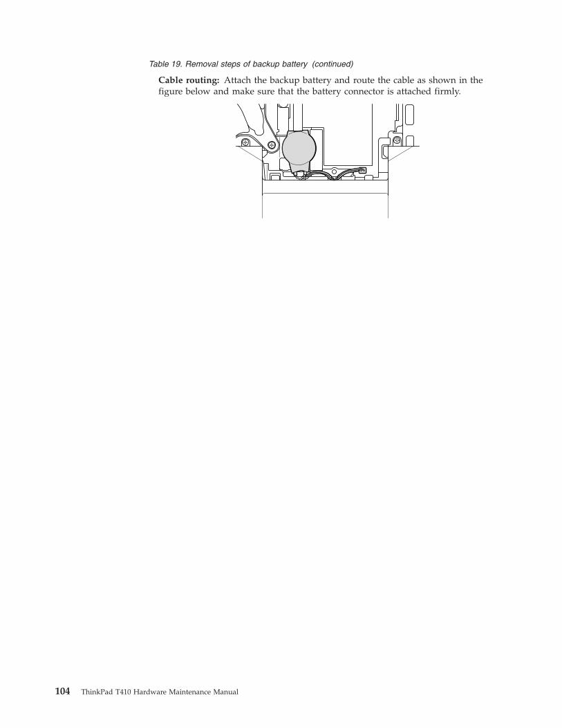
Table 19. Removal steps of backup battery (continued)
Cable routing: Attach the backup battery and route the cable as shown in thefigure below and make sure that the battery connector is attached firmly.
104 ThinkPad T410 Hardware Maintenance Manual
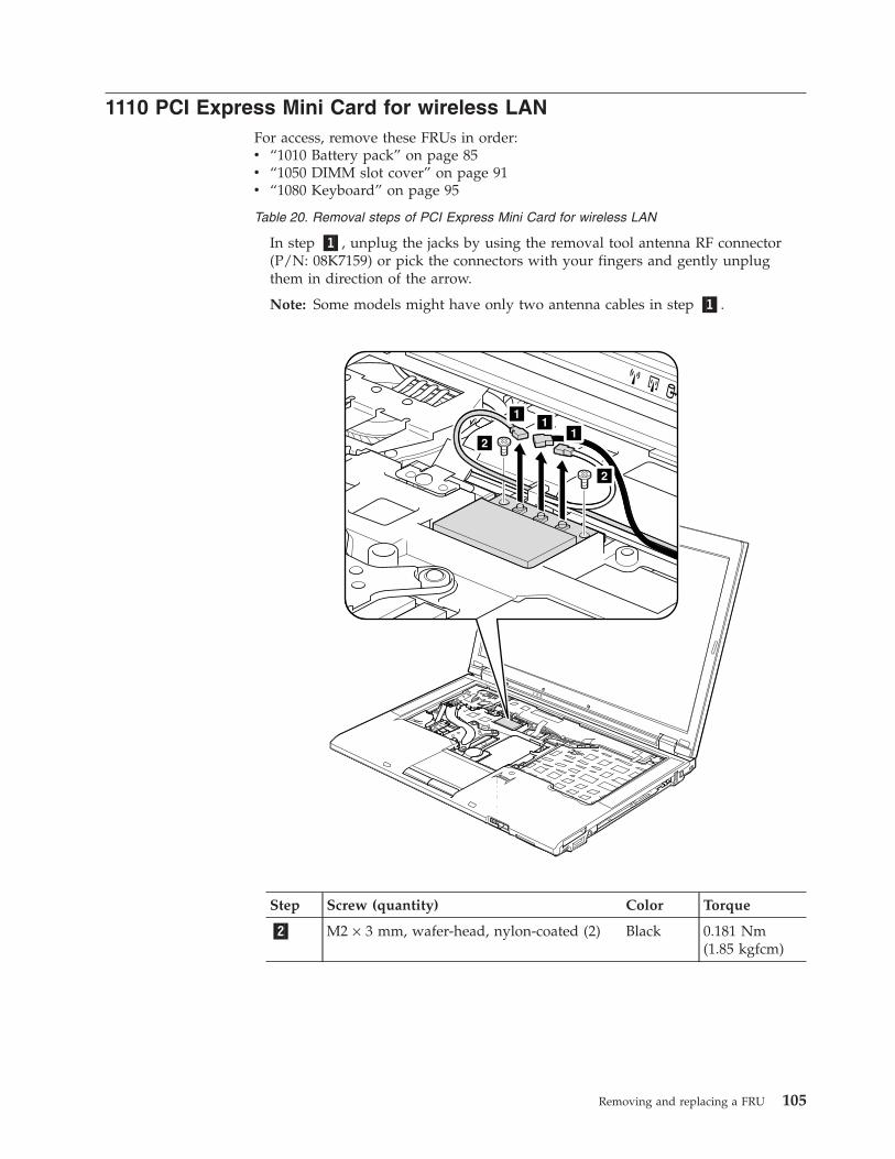
1110 PCI Express Mini Card for wireless LANFor access, remove these FRUs in order:v “1010 Battery pack” on page 85v “1050 DIMM slot cover” on page 91v “1080 Keyboard” on page 95
Table 20. Removal steps of PCI Express Mini Card for wireless LAN
In step �1�, unplug the jacks by using the removal tool antenna RF connector(P/N: 08K7159) or pick the connectors with your fingers and gently unplugthem in direction of the arrow.
Note: Some models might have only two antenna cables in step �1�.
1
11
2
2
Step Screw (quantity) Color Torque
�2� M2 × 3 mm, wafer-head, nylon-coated (2) Black 0.181 Nm(1.85 kgfcm)
Removing and replacing a FRU 105
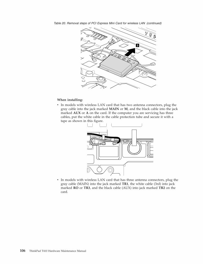
Table 20. Removal steps of PCI Express Mini Card for wireless LAN (continued)
3
When installing:
v In models with wireless LAN card that has two antenna connectors, plug thegray cable into the jack marked MAIN or M, and the black cable into the jackmarked AUX or A on the card. If the computer you are servicing has threecables, put the white cable in the cable protection tube and secure it with atape as shown in this figure.
v In models with wireless LAN card that has three antenna connectors, plug thegray cable (MAIN) into the jack marked TR1, the white cable (3rd) into jackmarked RO or TR3, and the black cable (AUX) into jack marked TR2 on thecard.
106 ThinkPad T410 Hardware Maintenance Manual
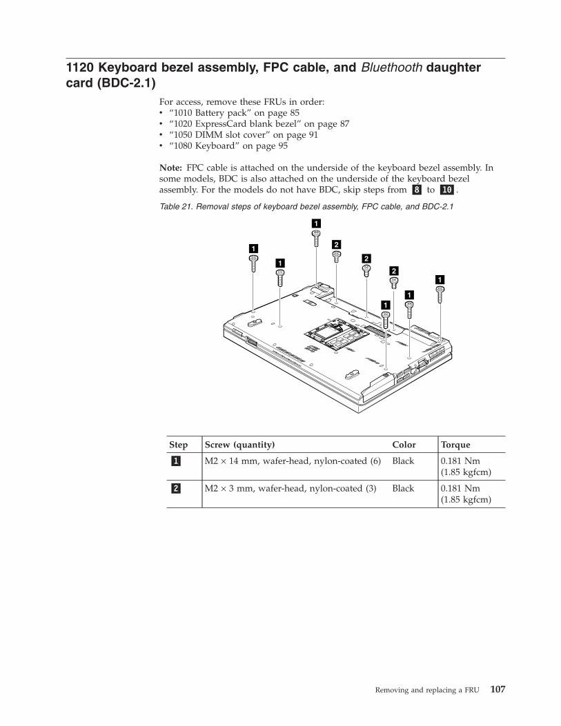
1120 Keyboard bezel assembly, FPC cable, and Bluethooth daughtercard (BDC-2.1)
For access, remove these FRUs in order:v “1010 Battery pack” on page 85v “1020 ExpressCard blank bezel” on page 87v “1050 DIMM slot cover” on page 91v “1080 Keyboard” on page 95
Note: FPC cable is attached on the underside of the keyboard bezel assembly. Insome models, BDC is also attached on the underside of the keyboard bezelassembly. For the models do not have BDC, skip steps from �8� to �10�.
Table 21. Removal steps of keyboard bezel assembly, FPC cable, and BDC-2.1
1
1
1
11
1
2
2
2
Step Screw (quantity) Color Torque
�1� M2 × 14 mm, wafer-head, nylon-coated (6) Black 0.181 Nm(1.85 kgfcm)
�2� M2 × 3 mm, wafer-head, nylon-coated (3) Black 0.181 Nm(1.85 kgfcm)
Removing and replacing a FRU 107
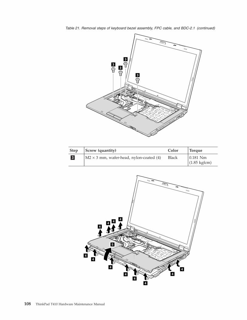
Table 21. Removal steps of keyboard bezel assembly, FPC cable, and BDC-2.1 (continued)
3
3
3
3
Step Screw (quantity) Color Torque
�3� M2 × 3 mm, wafer-head, nylon-coated (4) Black 0.181 Nm(1.85 kgfcm)
4
4
44 4
4
4
4
44
4
4
5
108 ThinkPad T410 Hardware Maintenance Manual
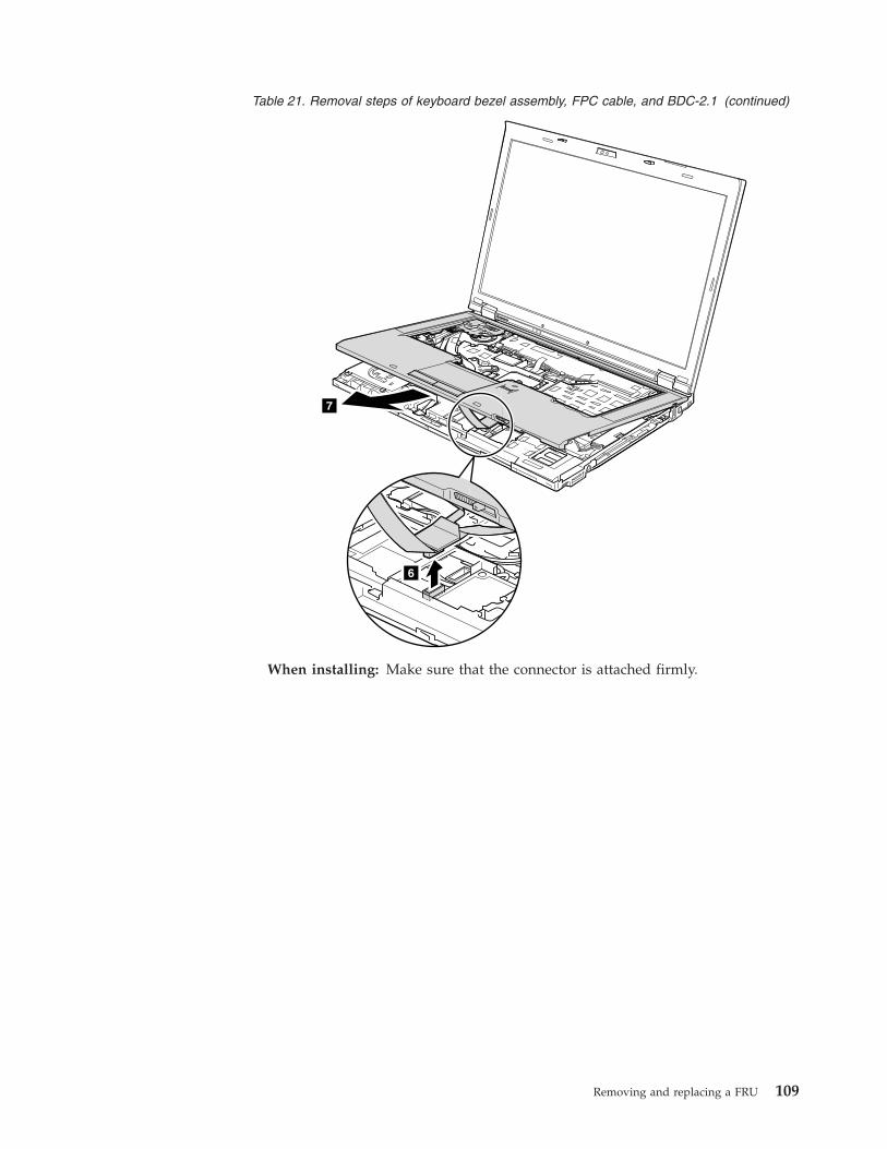
Table 21. Removal steps of keyboard bezel assembly, FPC cable, and BDC-2.1 (continued)
6
7
When installing: Make sure that the connector is attached firmly.
Removing and replacing a FRU 109
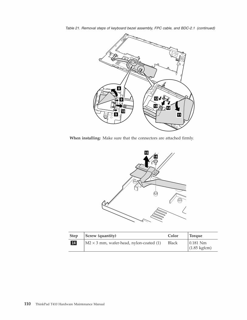
Table 21. Removal steps of keyboard bezel assembly, FPC cable, and BDC-2.1 (continued)
8
9
9
10
12
11
1213
When installing: Make sure that the connectors are attached firmly.
1415
Step Screw (quantity) Color Torque
�14� M2 × 3 mm, wafer-head, nylon-coated (1) Black 0.181 Nm(1.85 kgfcm)
110 ThinkPad T410 Hardware Maintenance Manual
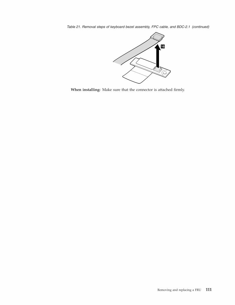
Table 21. Removal steps of keyboard bezel assembly, FPC cable, and BDC-2.1 (continued)
16
When installing: Make sure that the connector is attached firmly.
Removing and replacing a FRU 111
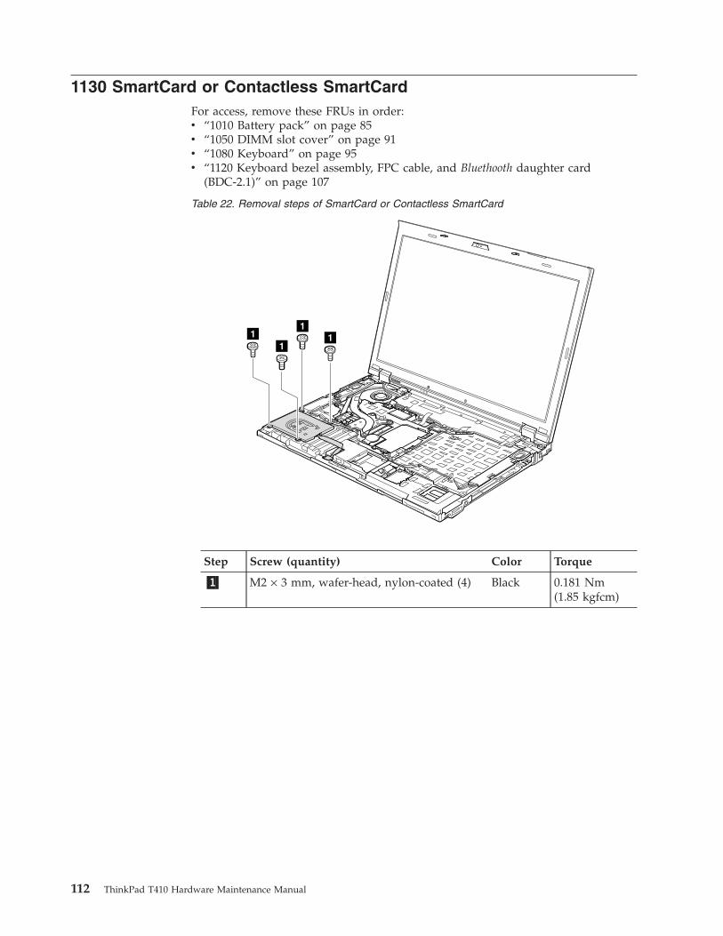
1130 SmartCard or Contactless SmartCardFor access, remove these FRUs in order:v “1010 Battery pack” on page 85v “1050 DIMM slot cover” on page 91v “1080 Keyboard” on page 95v “1120 Keyboard bezel assembly, FPC cable, and Bluethooth daughter card
(BDC-2.1)” on page 107
Table 22. Removal steps of SmartCard or Contactless SmartCard
11
11
Step Screw (quantity) Color Torque
�1� M2 × 3 mm, wafer-head, nylon-coated (4) Black 0.181 Nm(1.85 kgfcm)
112 ThinkPad T410 Hardware Maintenance Manual
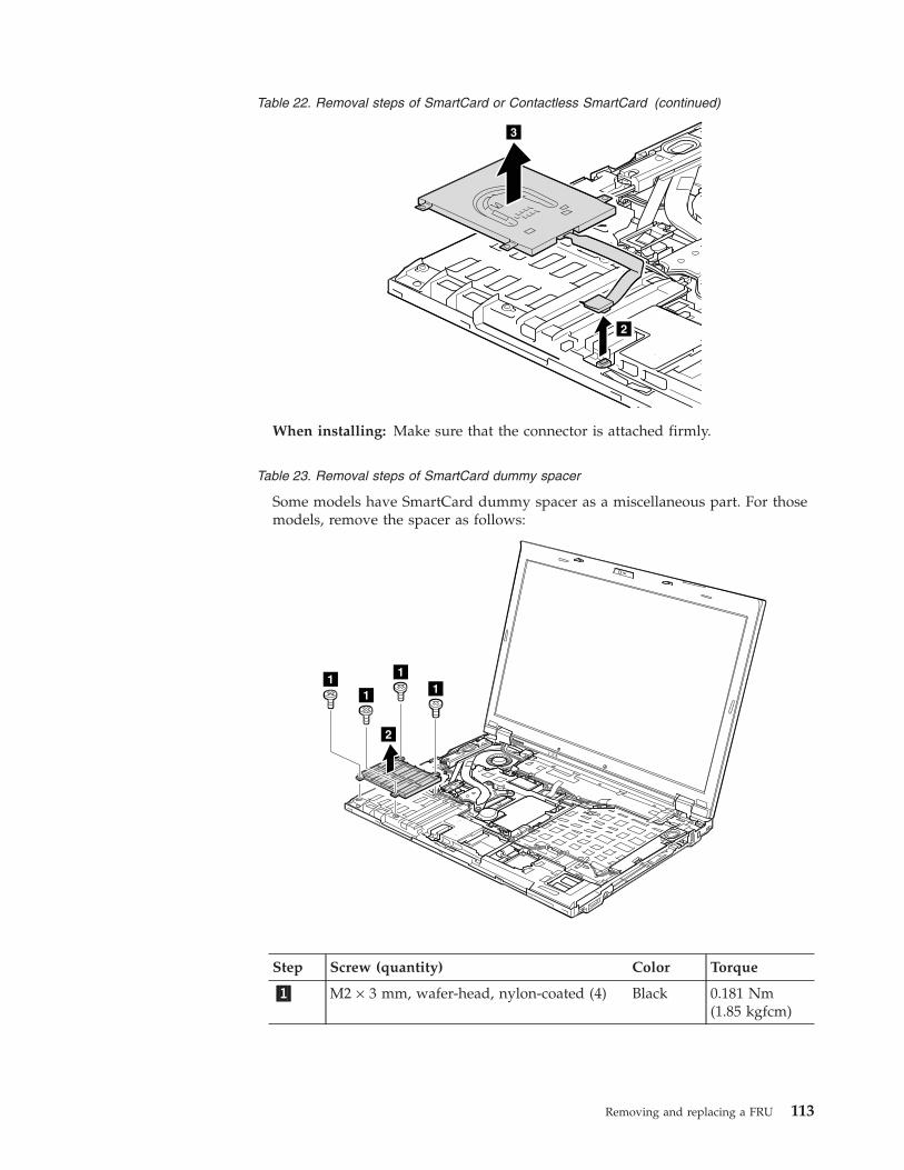
Table 22. Removal steps of SmartCard or Contactless SmartCard (continued)
2
3
When installing: Make sure that the connector is attached firmly.
Table 23. Removal steps of SmartCard dummy spacer
Some models have SmartCard dummy spacer as a miscellaneous part. For thosemodels, remove the spacer as follows:
1
2
111
Step Screw (quantity) Color Torque
�1� M2 × 3 mm, wafer-head, nylon-coated (4) Black 0.181 Nm(1.85 kgfcm)
Removing and replacing a FRU 113
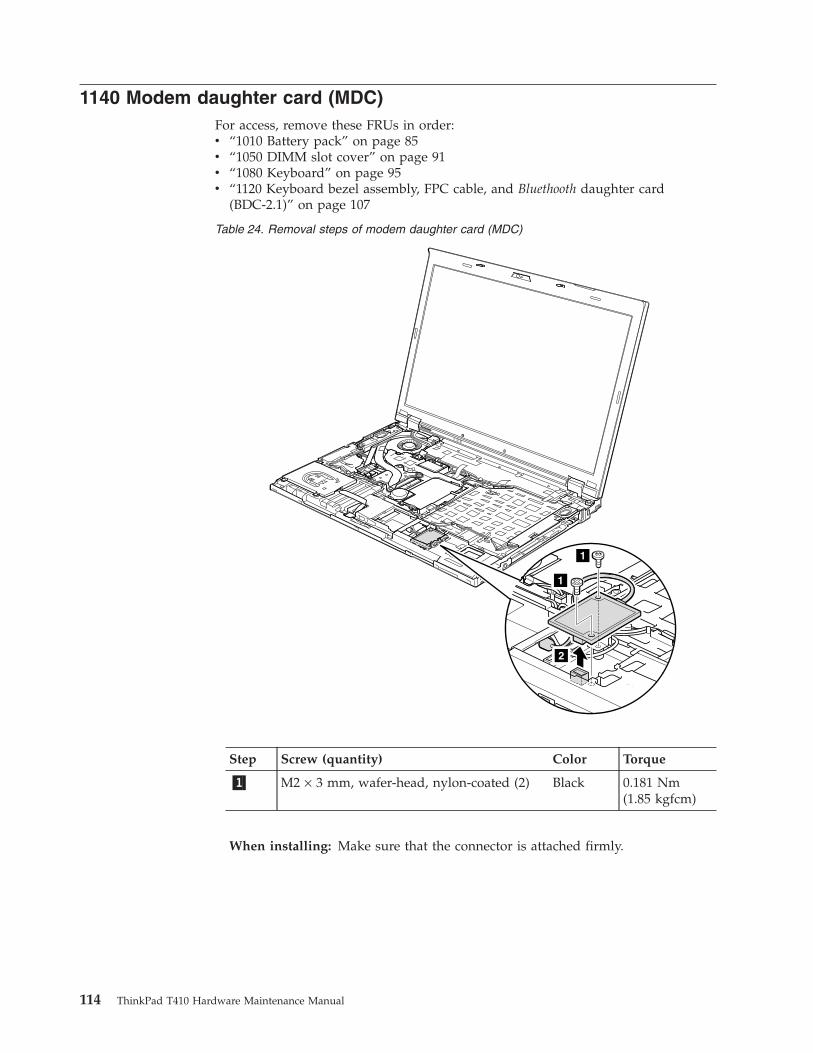
1140 Modem daughter card (MDC)For access, remove these FRUs in order:v “1010 Battery pack” on page 85v “1050 DIMM slot cover” on page 91v “1080 Keyboard” on page 95v “1120 Keyboard bezel assembly, FPC cable, and Bluethooth daughter card
(BDC-2.1)” on page 107
Table 24. Removal steps of modem daughter card (MDC)
1
1
2
Step Screw (quantity) Color Torque
�1� M2 × 3 mm, wafer-head, nylon-coated (2) Black 0.181 Nm(1.85 kgfcm)
When installing: Make sure that the connector is attached firmly.
114 ThinkPad T410 Hardware Maintenance Manual
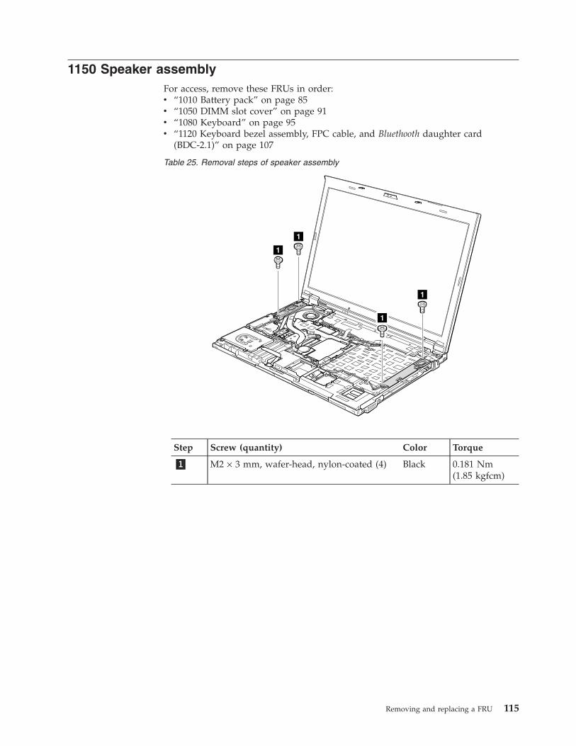
1150 Speaker assemblyFor access, remove these FRUs in order:v “1010 Battery pack” on page 85v “1050 DIMM slot cover” on page 91v “1080 Keyboard” on page 95v “1120 Keyboard bezel assembly, FPC cable, and Bluethooth daughter card
(BDC-2.1)” on page 107
Table 25. Removal steps of speaker assembly
1
1
1
1
Step Screw (quantity) Color Torque
�1� M2 × 3 mm, wafer-head, nylon-coated (4) Black 0.181 Nm(1.85 kgfcm)
Removing and replacing a FRU 115
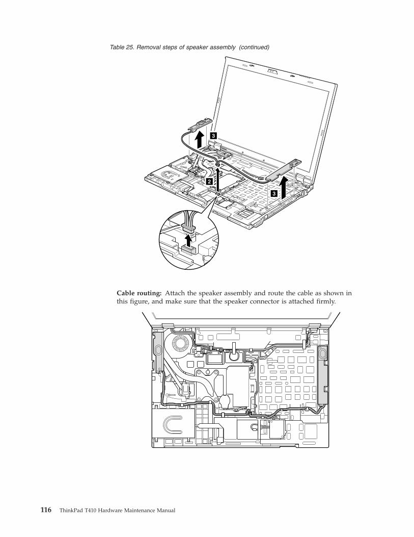
Table 25. Removal steps of speaker assembly (continued)
3
3
2
Cable routing: Attach the speaker assembly and route the cable as shown inthis figure, and make sure that the speaker connector is attached firmly.
116 ThinkPad T410 Hardware Maintenance Manual
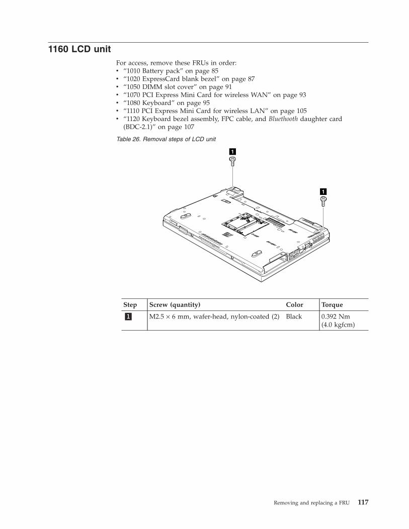
1160 LCD unitFor access, remove these FRUs in order:v “1010 Battery pack” on page 85v “1020 ExpressCard blank bezel” on page 87v “1050 DIMM slot cover” on page 91v “1070 PCI Express Mini Card for wireless WAN” on page 93v “1080 Keyboard” on page 95v “1110 PCI Express Mini Card for wireless LAN” on page 105v “1120 Keyboard bezel assembly, FPC cable, and Bluethooth daughter card
(BDC-2.1)” on page 107
Table 26. Removal steps of LCD unit
1
1
Step Screw (quantity) Color Torque
�1� M2.5 × 6 mm, wafer-head, nylon-coated (2) Black 0.392 Nm(4.0 kgfcm)
Removing and replacing a FRU 117
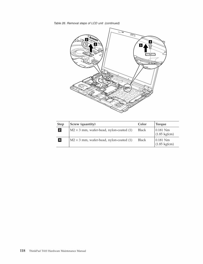
Table 26. Removal steps of LCD unit (continued)
2
34
5
Step Screw (quantity) Color Torque
�2� M2 × 3 mm, wafer-head, nylon-coated (1) Black 0.181 Nm(1.85 kgfcm)
�4� M2 × 3 mm, wafer-head, nylon-coated (1) Black 0.181 Nm(1.85 kgfcm)
118 ThinkPad T410 Hardware Maintenance Manual
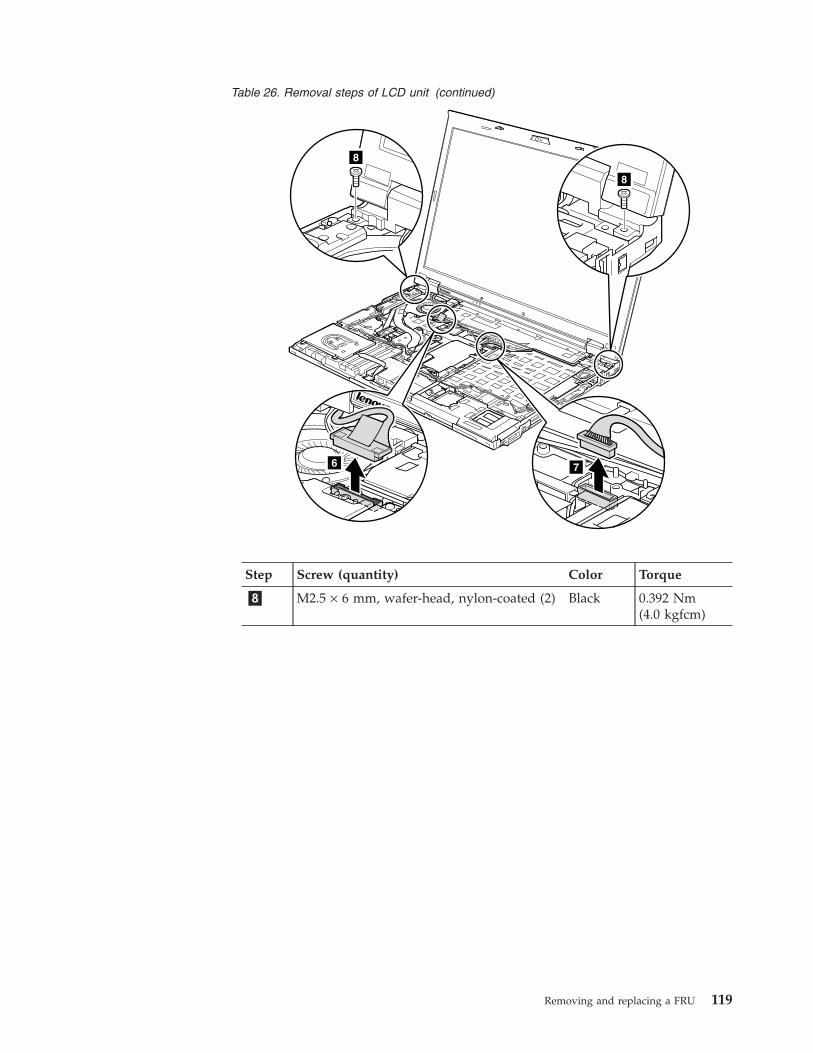
Table 26. Removal steps of LCD unit (continued)
8
8
76
Step Screw (quantity) Color Torque
�8� M2.5 × 6 mm, wafer-head, nylon-coated (2) Black 0.392 Nm(4.0 kgfcm)
Removing and replacing a FRU 119
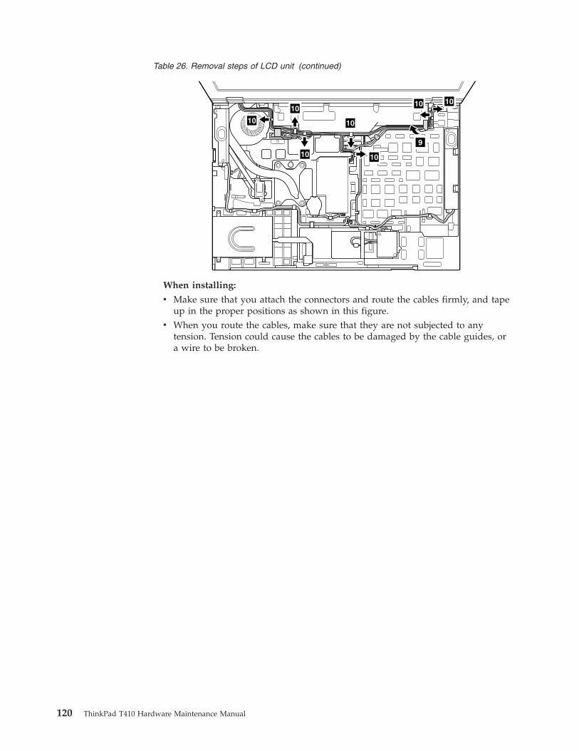
Table 26. Removal steps of LCD unit (continued)
9
1010
10
10
10
10
10
When installing:
v Make sure that you attach the connectors and route the cables firmly, and tapeup in the proper positions as shown in this figure.
v When you route the cables, make sure that they are not subjected to anytension. Tension could cause the cables to be damaged by the cable guides, ora wire to be broken.
120 ThinkPad T410 Hardware Maintenance Manual
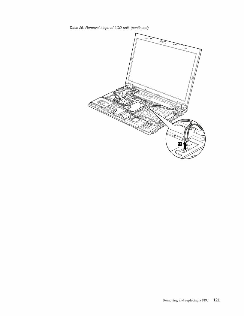
Table 26. Removal steps of LCD unit (continued)
11
Removing and replacing a FRU 121
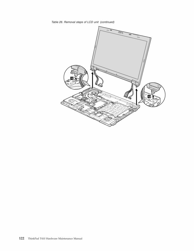
Table 26. Removal steps of LCD unit (continued)
12
12
122 ThinkPad T410 Hardware Maintenance Manual
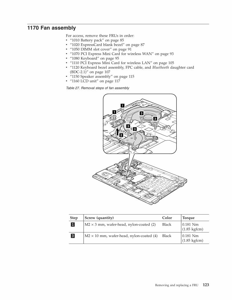
1170 Fan assemblyFor access, remove these FRUs in order:v “1010 Battery pack” on page 85v “1020 ExpressCard blank bezel” on page 87v “1050 DIMM slot cover” on page 91v “1070 PCI Express Mini Card for wireless WAN” on page 93v “1080 Keyboard” on page 95v “1110 PCI Express Mini Card for wireless LAN” on page 105v “1120 Keyboard bezel assembly, FPC cable, and Bluethooth daughter card
(BDC-2.1)” on page 107v “1150 Speaker assembly” on page 115v “1160 LCD unit” on page 117
Table 27. Removal steps of fan assembly
3
3
33
2
1
1
Step Screw (quantity) Color Torque
�1� M2 × 3 mm, wafer-head, nylon-coated (2) Black 0.181 Nm(1.85 kgfcm)
�3� M2 × 10 mm, wafer-head, nylon-coated (4) Black 0.181 Nm(1.85 kgfcm)
Removing and replacing a FRU 123
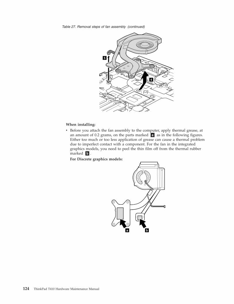
Table 27. Removal steps of fan assembly (continued)
4
5
When installing:
v Before you attach the fan assembly to the computer, apply thermal grease, atan amount of 0.2 grams, on the parts marked �a� as in the following figures.Either too much or too less application of grease can cause a thermal problemdue to imperfect contact with a component. For the fan in the integratedgraphics models, you need to peel the thin film off from the thermal rubbermarked �b�.For Discrete graphics models:
ba
124 ThinkPad T410 Hardware Maintenance Manual
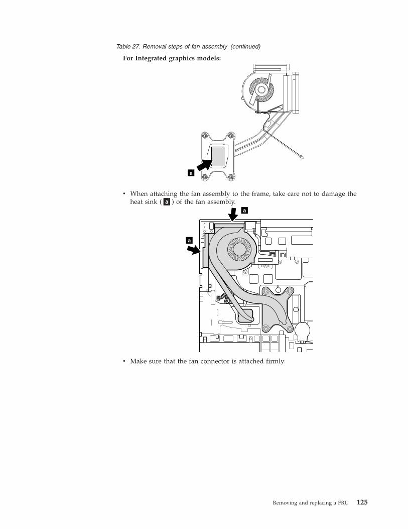
Table 27. Removal steps of fan assembly (continued)
For Integrated graphics models:
a
v When attaching the fan assembly to the frame, take care not to damage theheat sink (�a�) of the fan assembly.
a
a
v Make sure that the fan connector is attached firmly.
Removing and replacing a FRU 125
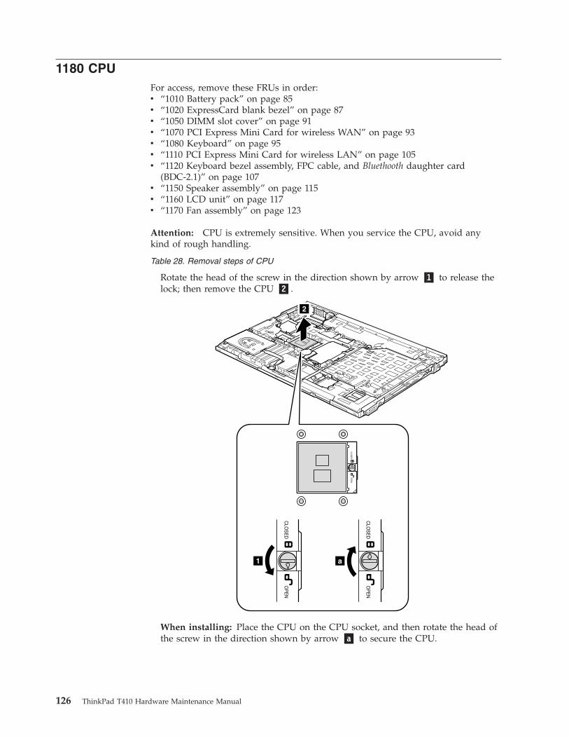
1180 CPUFor access, remove these FRUs in order:v “1010 Battery pack” on page 85v “1020 ExpressCard blank bezel” on page 87v “1050 DIMM slot cover” on page 91v “1070 PCI Express Mini Card for wireless WAN” on page 93v “1080 Keyboard” on page 95v “1110 PCI Express Mini Card for wireless LAN” on page 105v “1120 Keyboard bezel assembly, FPC cable, and Bluethooth daughter card
(BDC-2.1)” on page 107v “1150 Speaker assembly” on page 115v “1160 LCD unit” on page 117v “1170 Fan assembly” on page 123
Attention: CPU is extremely sensitive. When you service the CPU, avoid anykind of rough handling.
Table 28. Removal steps of CPU
Rotate the head of the screw in the direction shown by arrow �1� to release thelock; then remove the CPU �2�.
2
1 a
When installing: Place the CPU on the CPU socket, and then rotate the head ofthe screw in the direction shown by arrow �a� to secure the CPU.
126 ThinkPad T410 Hardware Maintenance Manual
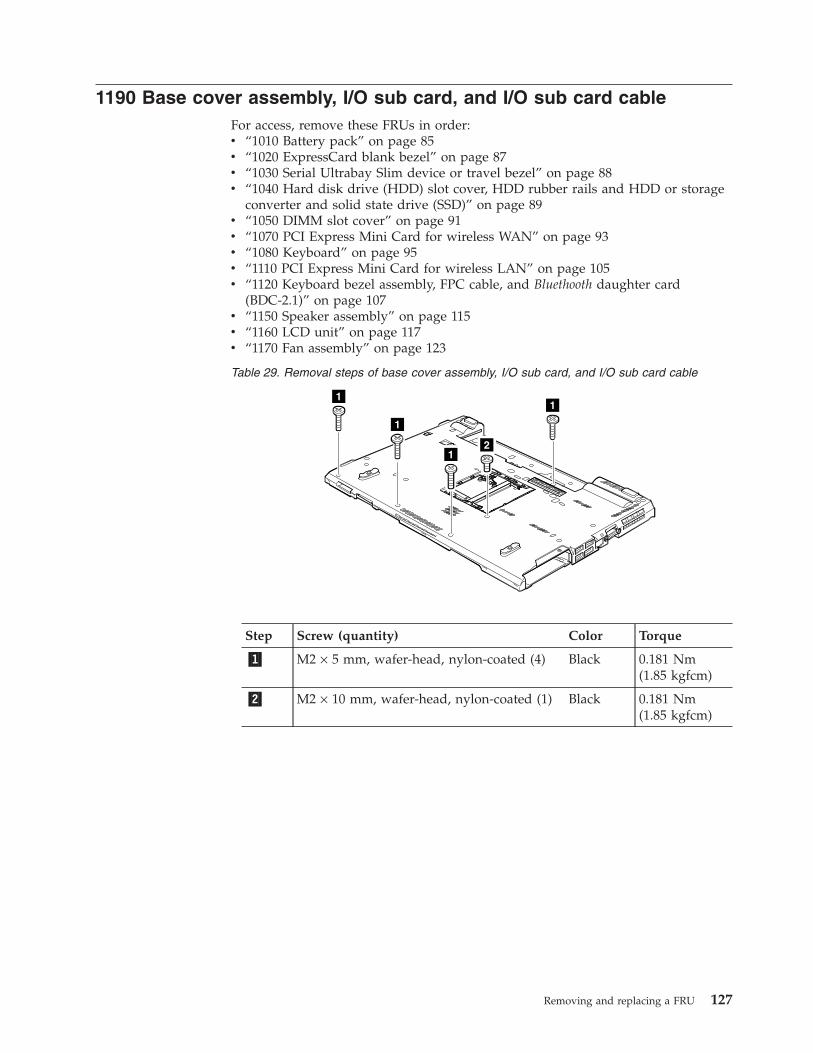
1190 Base cover assembly, I/O sub card, and I/O sub card cableFor access, remove these FRUs in order:v “1010 Battery pack” on page 85v “1020 ExpressCard blank bezel” on page 87v “1030 Serial Ultrabay Slim device or travel bezel” on page 88v “1040 Hard disk drive (HDD) slot cover, HDD rubber rails and HDD or storage
converter and solid state drive (SSD)” on page 89v “1050 DIMM slot cover” on page 91v “1070 PCI Express Mini Card for wireless WAN” on page 93v “1080 Keyboard” on page 95v “1110 PCI Express Mini Card for wireless LAN” on page 105v “1120 Keyboard bezel assembly, FPC cable, and Bluethooth daughter card
(BDC-2.1)” on page 107v “1150 Speaker assembly” on page 115v “1160 LCD unit” on page 117v “1170 Fan assembly” on page 123
Table 29. Removal steps of base cover assembly, I/O sub card, and I/O sub card cable
11
1
12
Step Screw (quantity) Color Torque
�1� M2 × 5 mm, wafer-head, nylon-coated (4) Black 0.181 Nm(1.85 kgfcm)
�2� M2 × 10 mm, wafer-head, nylon-coated (1) Black 0.181 Nm(1.85 kgfcm)
Removing and replacing a FRU 127
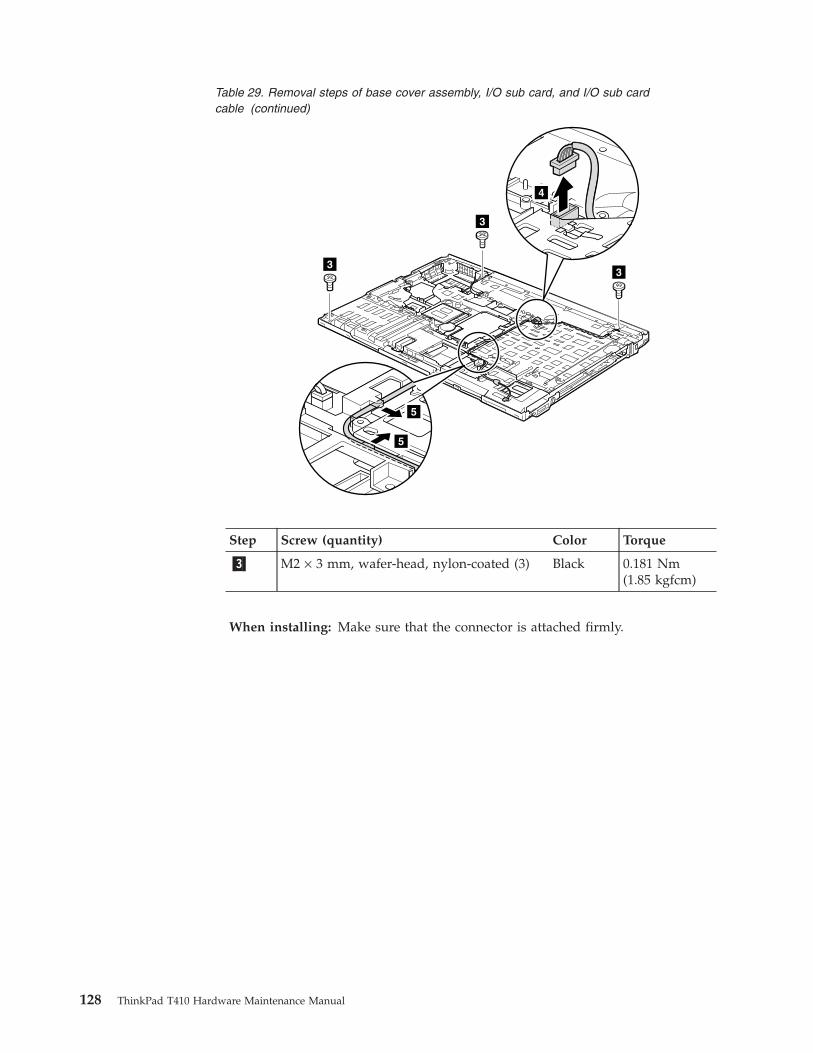
Table 29. Removal steps of base cover assembly, I/O sub card, and I/O sub cardcable (continued)
4
3
33
5
5
Step Screw (quantity) Color Torque
�3� M2 × 3 mm, wafer-head, nylon-coated (3) Black 0.181 Nm(1.85 kgfcm)
When installing: Make sure that the connector is attached firmly.
128 ThinkPad T410 Hardware Maintenance Manual
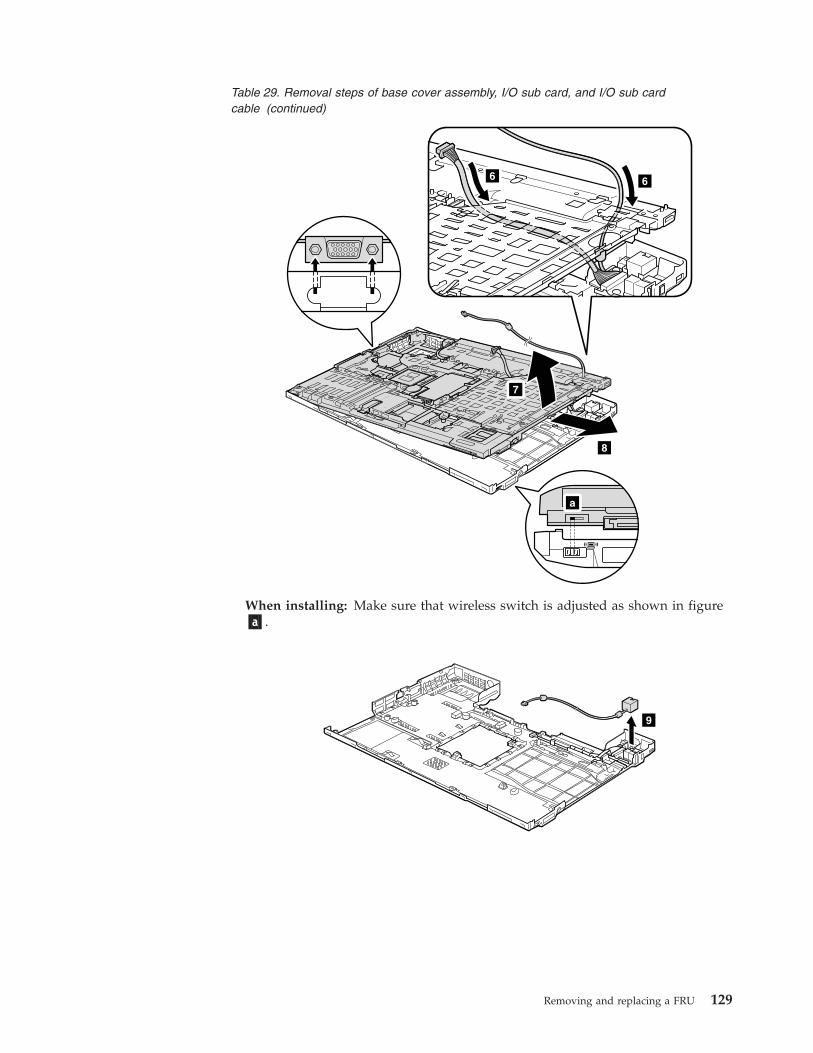
Table 29. Removal steps of base cover assembly, I/O sub card, and I/O sub cardcable (continued)
8
7
6 6
a
When installing: Make sure that wireless switch is adjusted as shown in figure�a�.
9
Removing and replacing a FRU 129
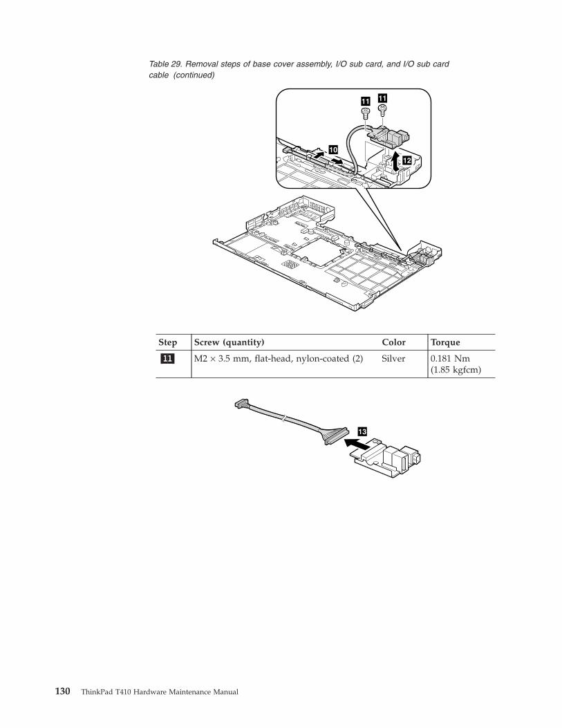
Table 29. Removal steps of base cover assembly, I/O sub card, and I/O sub cardcable (continued)
10
1111
12
Step Screw (quantity) Color Torque
�11� M2 × 3.5 mm, flat-head, nylon-coated (2) Silver 0.181 Nm(1.85 kgfcm)
13
130 ThinkPad T410 Hardware Maintenance Manual
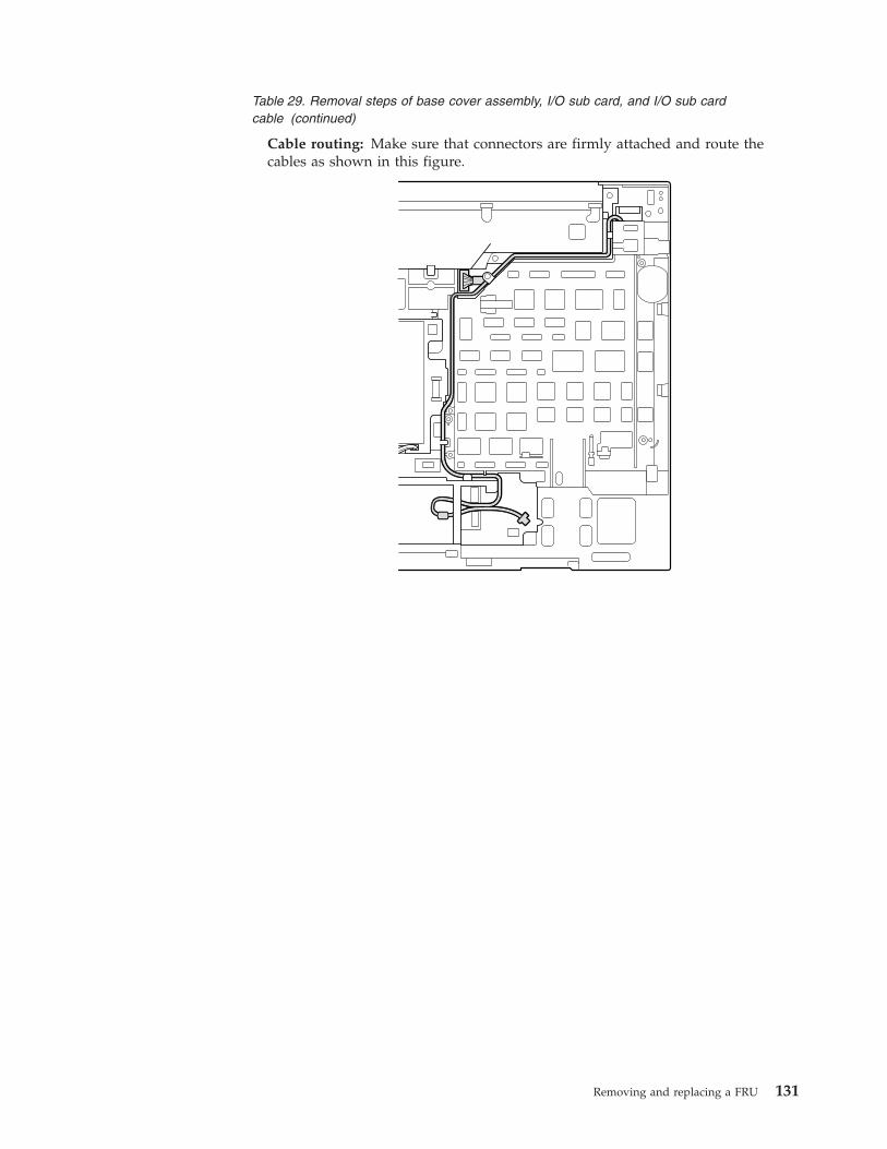
Table 29. Removal steps of base cover assembly, I/O sub card, and I/O sub cardcable (continued)
Cable routing: Make sure that connectors are firmly attached and route thecables as shown in this figure.
Removing and replacing a FRU 131
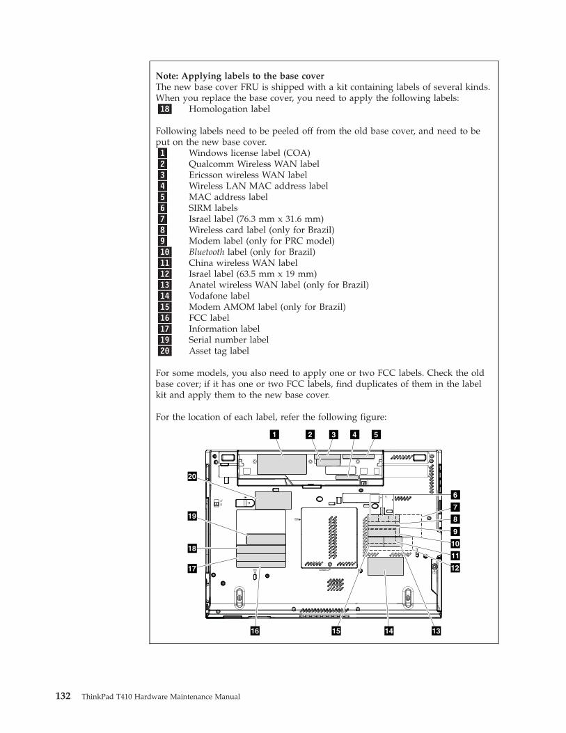
Note: Applying labels to the base coverThe new base cover FRU is shipped with a kit containing labels of several kinds.When you replace the base cover, you need to apply the following labels:�18� Homologation label
Following labels need to be peeled off from the old base cover, and need to beput on the new base cover.�1� Windows license label (COA)�2� Qualcomm Wireless WAN label�3� Ericsson wireless WAN label�4� Wireless LAN MAC address label�5� MAC address label�6� SIRM labels�7� Israel label (76.3 mm x 31.6 mm)�8� Wireless card label (only for Brazil)�9� Modem label (only for PRC model)�10� Bluetooth label (only for Brazil)�11� China wireless WAN label�12� Israel label (63.5 mm x 19 mm)�13� Anatel wireless WAN label (only for Brazil)�14� Vodafone label�15� Modem AMOM label (only for Brazil)�16� FCC label�17� Information label�19� Serial number label�20� Asset tag label
For some models, you also need to apply one or two FCC labels. Check the oldbase cover; if it has one or two FCC labels, find duplicates of them in the labelkit and apply them to the new base cover.
For the location of each label, refer the following figure:
1 3
7
8
11
10
9
12
20
19
18
17
54
1415 1316
6
2
132 ThinkPad T410 Hardware Maintenance Manual
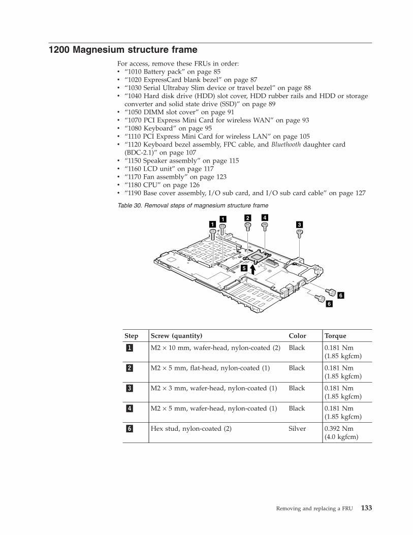
1200 Magnesium structure frameFor access, remove these FRUs in order:v “1010 Battery pack” on page 85v “1020 ExpressCard blank bezel” on page 87v “1030 Serial Ultrabay Slim device or travel bezel” on page 88v “1040 Hard disk drive (HDD) slot cover, HDD rubber rails and HDD or storage
converter and solid state drive (SSD)” on page 89v “1050 DIMM slot cover” on page 91v “1070 PCI Express Mini Card for wireless WAN” on page 93v “1080 Keyboard” on page 95v “1110 PCI Express Mini Card for wireless LAN” on page 105v “1120 Keyboard bezel assembly, FPC cable, and Bluethooth daughter card
(BDC-2.1)” on page 107v “1150 Speaker assembly” on page 115v “1160 LCD unit” on page 117v “1170 Fan assembly” on page 123v “1180 CPU” on page 126v “1190 Base cover assembly, I/O sub card, and I/O sub card cable” on page 127
Table 30. Removal steps of magnesium structure frame
43
6
6
21
5
1
Step Screw (quantity) Color Torque
�1� M2 × 10 mm, wafer-head, nylon-coated (2) Black 0.181 Nm(1.85 kgfcm)
�2� M2 × 5 mm, flat-head, nylon-coated (1) Black 0.181 Nm(1.85 kgfcm)
�3� M2 × 3 mm, wafer-head, nylon-coated (1) Black 0.181 Nm(1.85 kgfcm)
�4� M2 × 5 mm, wafer-head, nylon-coated (1) Black 0.181 Nm(1.85 kgfcm)
�6� Hex stud, nylon-coated (2) Silver 0.392 Nm(4.0 kgfcm)
Removing and replacing a FRU 133
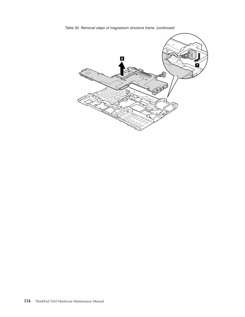
Table 30. Removal steps of magnesium structure frame (continued)
8
7
134 ThinkPad T410 Hardware Maintenance Manual
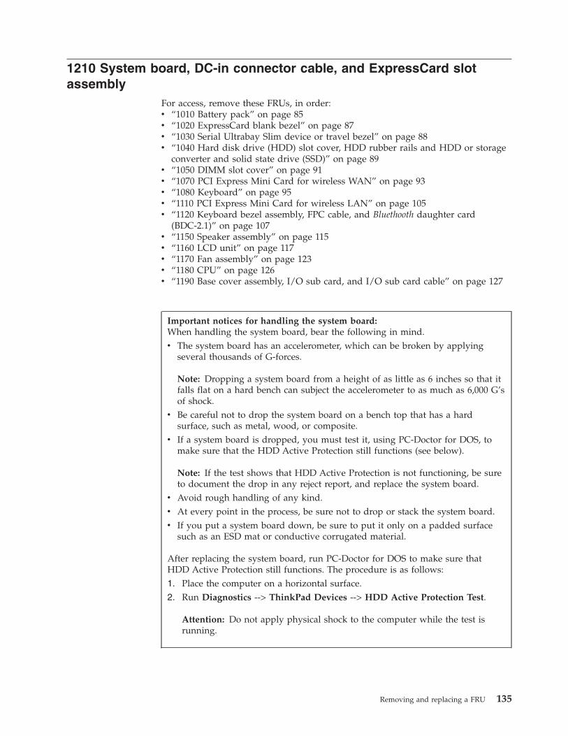
1210 System board, DC-in connector cable, and ExpressCard slotassembly
For access, remove these FRUs, in order:v “1010 Battery pack” on page 85v “1020 ExpressCard blank bezel” on page 87v “1030 Serial Ultrabay Slim device or travel bezel” on page 88v “1040 Hard disk drive (HDD) slot cover, HDD rubber rails and HDD or storage
converter and solid state drive (SSD)” on page 89v “1050 DIMM slot cover” on page 91v “1070 PCI Express Mini Card for wireless WAN” on page 93v “1080 Keyboard” on page 95v “1110 PCI Express Mini Card for wireless LAN” on page 105v “1120 Keyboard bezel assembly, FPC cable, and Bluethooth daughter card
(BDC-2.1)” on page 107v “1150 Speaker assembly” on page 115v “1160 LCD unit” on page 117v “1170 Fan assembly” on page 123v “1180 CPU” on page 126v “1190 Base cover assembly, I/O sub card, and I/O sub card cable” on page 127
Important notices for handling the system board:When handling the system board, bear the following in mind.v The system board has an accelerometer, which can be broken by applying
several thousands of G-forces.
Note: Dropping a system board from a height of as little as 6 inches so that itfalls flat on a hard bench can subject the accelerometer to as much as 6,000 G’sof shock.
v Be careful not to drop the system board on a bench top that has a hardsurface, such as metal, wood, or composite.
v If a system board is dropped, you must test it, using PC-Doctor for DOS, tomake sure that the HDD Active Protection still functions (see below).
Note: If the test shows that HDD Active Protection is not functioning, be sureto document the drop in any reject report, and replace the system board.
v Avoid rough handling of any kind.v At every point in the process, be sure not to drop or stack the system board.v If you put a system board down, be sure to put it only on a padded surface
such as an ESD mat or conductive corrugated material.
After replacing the system board, run PC-Doctor for DOS to make sure thatHDD Active Protection still functions. The procedure is as follows:1. Place the computer on a horizontal surface.2. Run Diagnostics --> ThinkPad Devices --> HDD Active Protection Test.
Attention: Do not apply physical shock to the computer while the test isrunning.
Removing and replacing a FRU 135
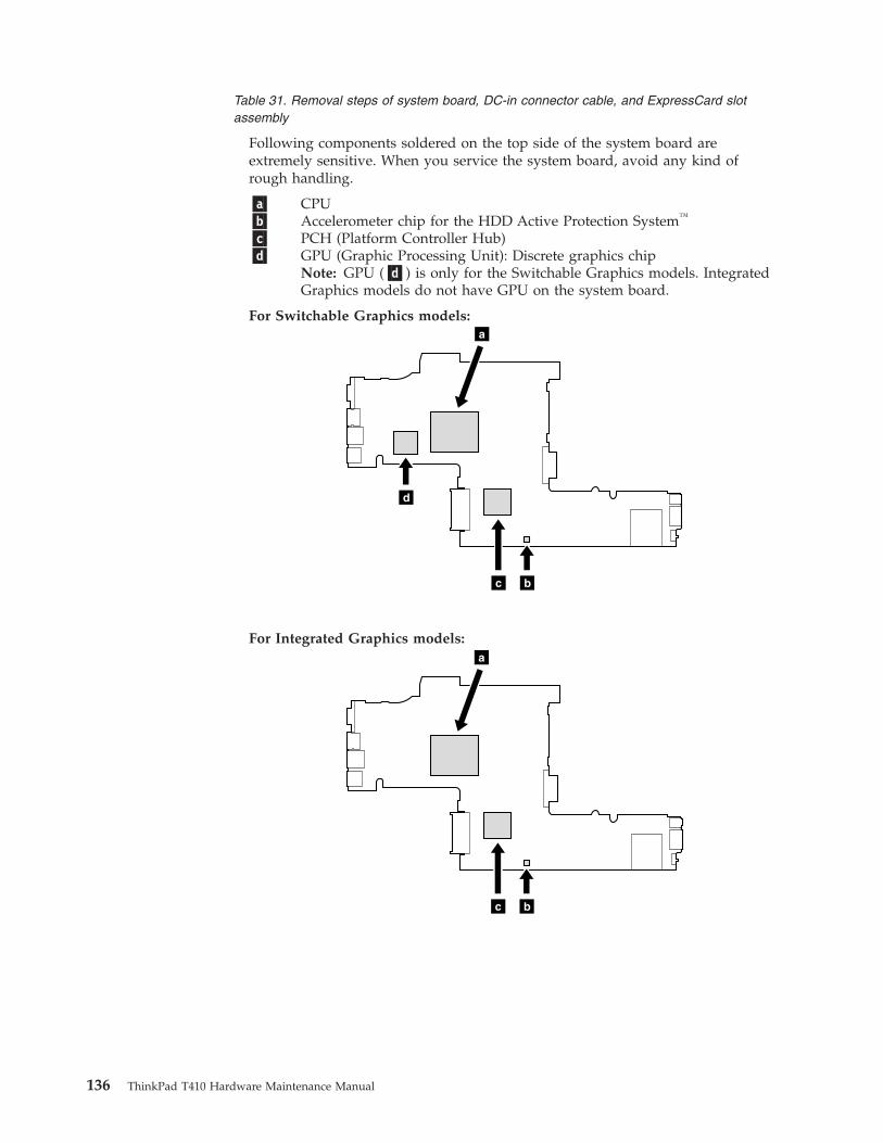
Table 31. Removal steps of system board, DC-in connector cable, and ExpressCard slotassembly
Following components soldered on the top side of the system board areextremely sensitive. When you service the system board, avoid any kind ofrough handling.
�a� CPU�b� Accelerometer chip for the HDD Active Protection System™
�c� PCH (Platform Controller Hub)�d� GPU (Graphic Processing Unit): Discrete graphics chip
Note: GPU (�d�) is only for the Switchable Graphics models. IntegratedGraphics models do not have GPU on the system board.
For Switchable Graphics models:
bc
d
a
For Integrated Graphics models:
bc
a
136 ThinkPad T410 Hardware Maintenance Manual
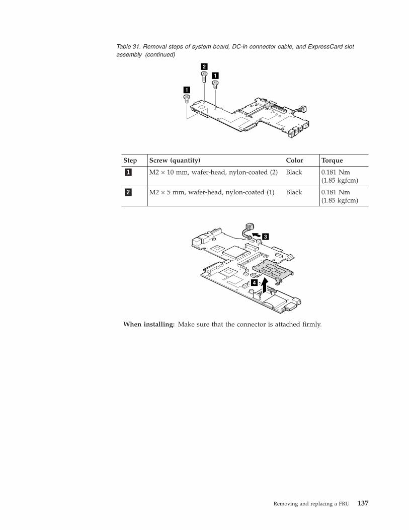
Table 31. Removal steps of system board, DC-in connector cable, and ExpressCard slotassembly (continued)
1
2
1
Step Screw (quantity) Color Torque
�1� M2 × 10 mm, wafer-head, nylon-coated (2) Black 0.181 Nm(1.85 kgfcm)
�2� M2 × 5 mm, wafer-head, nylon-coated (1) Black 0.181 Nm(1.85 kgfcm)
3
4
When installing: Make sure that the connector is attached firmly.
Removing and replacing a FRU 137
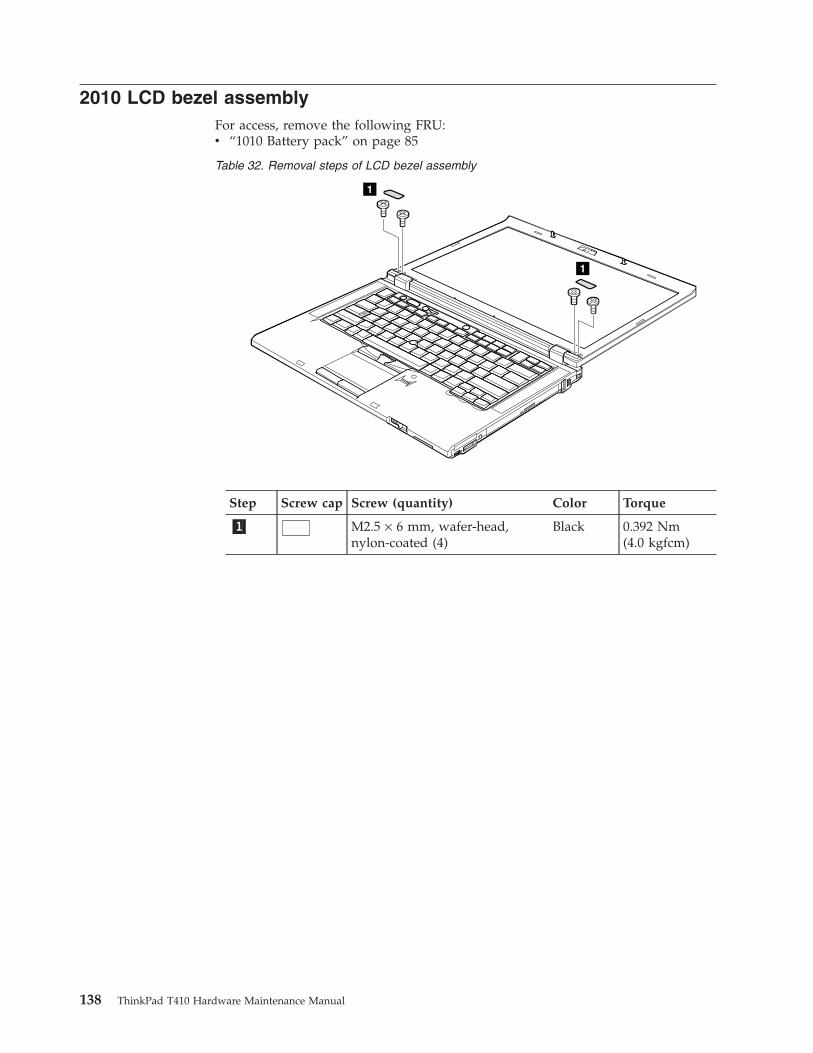
2010 LCD bezel assemblyFor access, remove the following FRU:v “1010 Battery pack” on page 85
Table 32. Removal steps of LCD bezel assembly
1
1
Step Screw cap Screw (quantity) Color Torque
�1� M2.5 × 6 mm, wafer-head,nylon-coated (4)
Black 0.392 Nm(4.0 kgfcm)
138 ThinkPad T410 Hardware Maintenance Manual
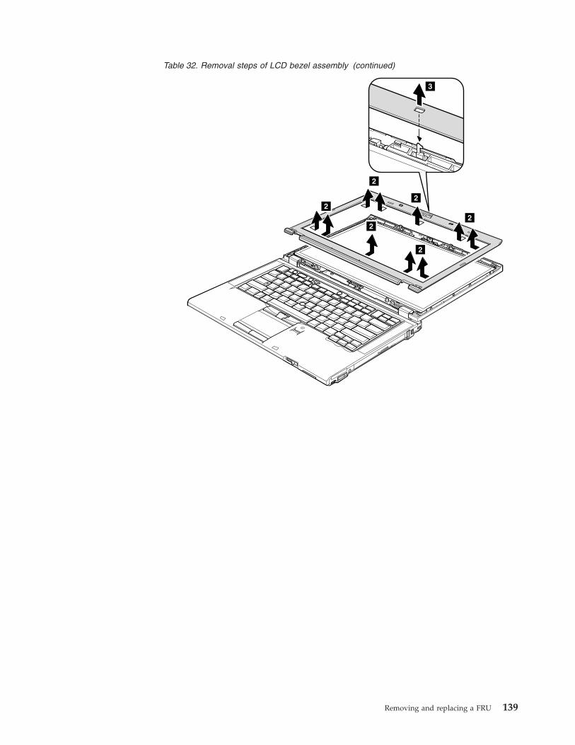
Table 32. Removal steps of LCD bezel assembly (continued)
2
2
2
2
2
3
2
Removing and replacing a FRU 139
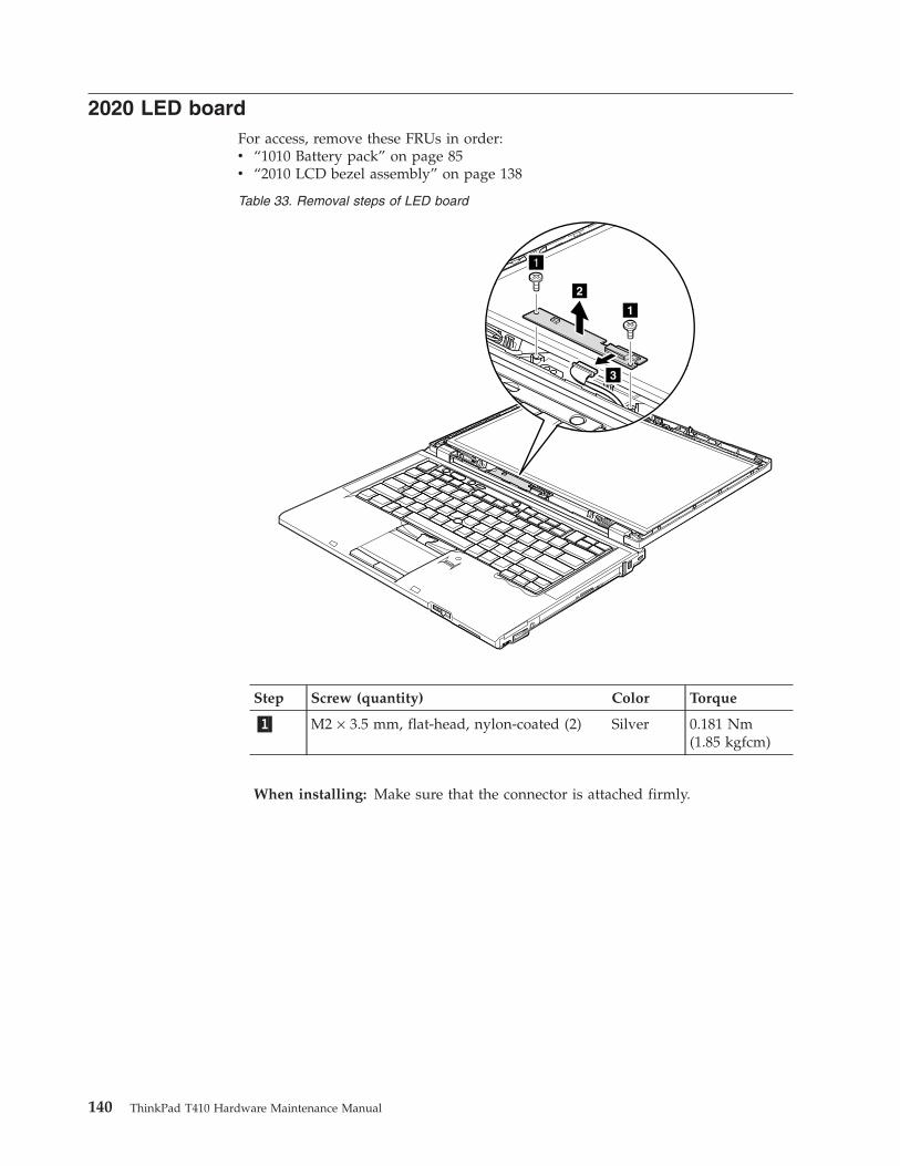
2020 LED boardFor access, remove these FRUs in order:v “1010 Battery pack” on page 85v “2010 LCD bezel assembly” on page 138
Table 33. Removal steps of LED board
1
1
3
2
Step Screw (quantity) Color Torque
�1� M2 × 3.5 mm, flat-head, nylon-coated (2) Silver 0.181 Nm(1.85 kgfcm)
When installing: Make sure that the connector is attached firmly.
140 ThinkPad T410 Hardware Maintenance Manual
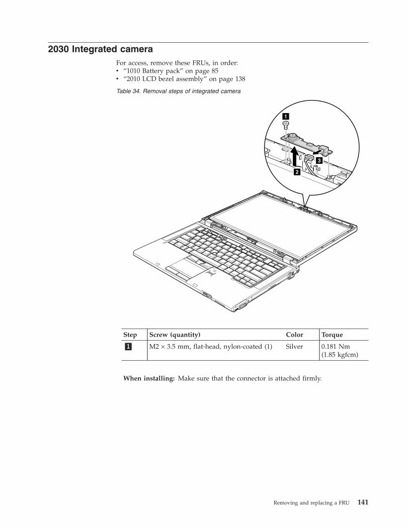
2030 Integrated cameraFor access, remove these FRUs, in order:v “1010 Battery pack” on page 85v “2010 LCD bezel assembly” on page 138
Table 34. Removal steps of integrated camera
1
2
3
Step Screw (quantity) Color Torque
�1� M2 × 3.5 mm, flat-head, nylon-coated (1) Silver 0.181 Nm(1.85 kgfcm)
When installing: Make sure that the connector is attached firmly.
Removing and replacing a FRU 141
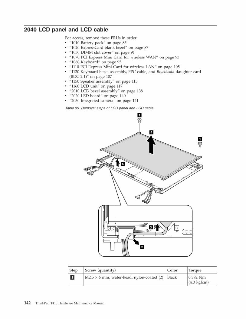
2040 LCD panel and LCD cableFor access, remove these FRUs in order:v “1010 Battery pack” on page 85v “1020 ExpressCard blank bezel” on page 87v “1050 DIMM slot cover” on page 91v “1070 PCI Express Mini Card for wireless WAN” on page 93v “1080 Keyboard” on page 95v “1110 PCI Express Mini Card for wireless LAN” on page 105v “1120 Keyboard bezel assembly, FPC cable, and Bluethooth daughter card
(BDC-2.1)” on page 107v “1150 Speaker assembly” on page 115v “1160 LCD unit” on page 117v “2010 LCD bezel assembly” on page 138v “2020 LED board” on page 140v “2030 Integrated camera” on page 141
Table 35. Removal steps of LCD panel and LCD cable
4
5
1
1
2
3
Step Screw (quantity) Color Torque
�1� M2.5 × 6 mm, wafer-head, nylon-coated (2) Black 0.392 Nm(4.0 kgfcm)
142 ThinkPad T410 Hardware Maintenance Manual
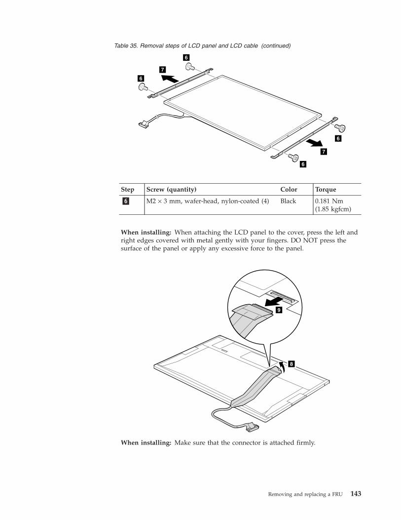
Table 35. Removal steps of LCD panel and LCD cable (continued)
6
6
7
7
6
6
Step Screw (quantity) Color Torque
�6� M2 × 3 mm, wafer-head, nylon-coated (4) Black 0.181 Nm(1.85 kgfcm)
When installing: When attaching the LCD panel to the cover, press the left andright edges covered with metal gently with your fingers. DO NOT press thesurface of the panel or apply any excessive force to the panel.
8
9
When installing: Make sure that the connector is attached firmly.
Removing and replacing a FRU 143
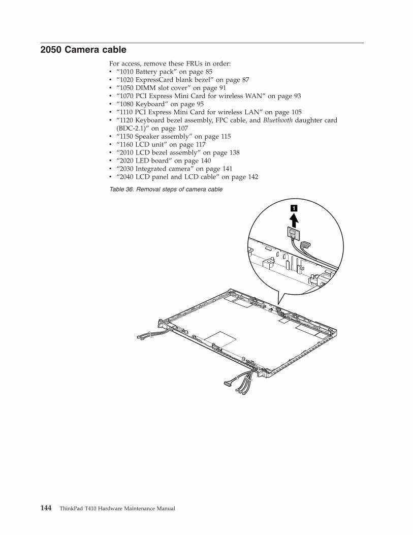
2050 Camera cableFor access, remove these FRUs in order:v “1010 Battery pack” on page 85v “1020 ExpressCard blank bezel” on page 87v “1050 DIMM slot cover” on page 91v “1070 PCI Express Mini Card for wireless WAN” on page 93v “1080 Keyboard” on page 95v “1110 PCI Express Mini Card for wireless LAN” on page 105v “1120 Keyboard bezel assembly, FPC cable, and Bluethooth daughter card
(BDC-2.1)” on page 107v “1150 Speaker assembly” on page 115v “1160 LCD unit” on page 117v “2010 LCD bezel assembly” on page 138v “2020 LED board” on page 140v “2030 Integrated camera” on page 141v “2040 LCD panel and LCD cable” on page 142
Table 36. Removal steps of camera cable
1
144 ThinkPad T410 Hardware Maintenance Manual
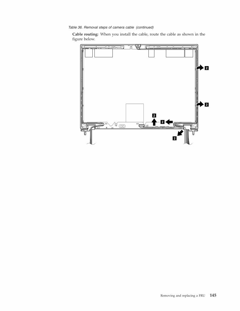
Table 36. Removal steps of camera cable (continued)
Cable routing: When you install the cable, route the cable as shown in thefigure below.
2
2
2
2
2
Removing and replacing a FRU 145
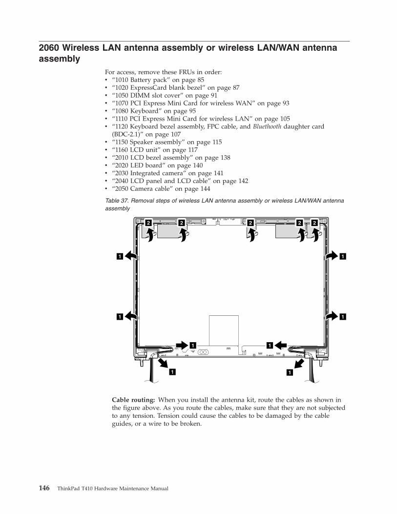
2060 Wireless LAN antenna assembly or wireless LAN/WAN antennaassembly
For access, remove these FRUs in order:v “1010 Battery pack” on page 85v “1020 ExpressCard blank bezel” on page 87v “1050 DIMM slot cover” on page 91v “1070 PCI Express Mini Card for wireless WAN” on page 93v “1080 Keyboard” on page 95v “1110 PCI Express Mini Card for wireless LAN” on page 105v “1120 Keyboard bezel assembly, FPC cable, and Bluethooth daughter card
(BDC-2.1)” on page 107v “1150 Speaker assembly” on page 115v “1160 LCD unit” on page 117v “2010 LCD bezel assembly” on page 138v “2020 LED board” on page 140v “2030 Integrated camera” on page 141v “2040 LCD panel and LCD cable” on page 142v “2050 Camera cable” on page 144
Table 37. Removal steps of wireless LAN antenna assembly or wireless LAN/WAN antennaassembly
1
1
1
1
1
1
2 2 2 2 2
1
1
Cable routing: When you install the antenna kit, route the cables as shown inthe figure above. As you route the cables, make sure that they are not subjectedto any tension. Tension could cause the cables to be damaged by the cableguides, or a wire to be broken.
146 ThinkPad T410 Hardware Maintenance Manual
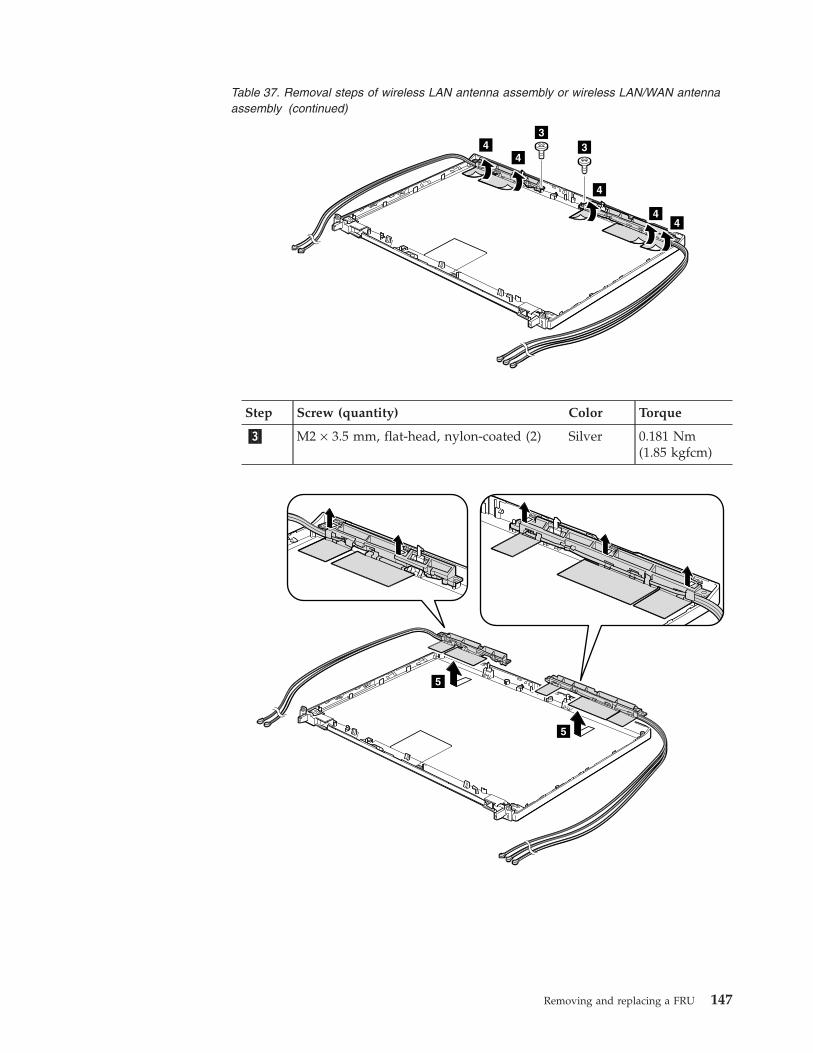
Table 37. Removal steps of wireless LAN antenna assembly or wireless LAN/WAN antennaassembly (continued)
44
4
33
44
Step Screw (quantity) Color Torque
�3� M2 × 3.5 mm, flat-head, nylon-coated (2) Silver 0.181 Nm(1.85 kgfcm)
5
5
Removing and replacing a FRU 147
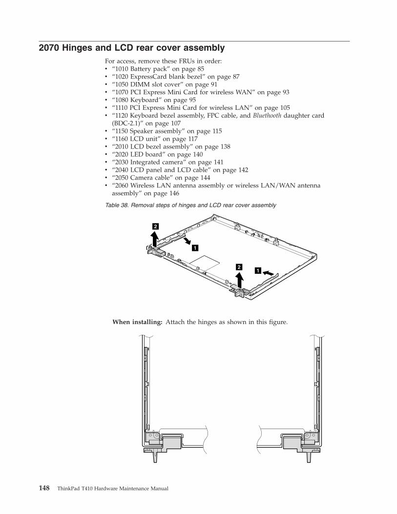
2070 Hinges and LCD rear cover assemblyFor access, remove these FRUs in order:v “1010 Battery pack” on page 85v “1020 ExpressCard blank bezel” on page 87v “1050 DIMM slot cover” on page 91v “1070 PCI Express Mini Card for wireless WAN” on page 93v “1080 Keyboard” on page 95v “1110 PCI Express Mini Card for wireless LAN” on page 105v “1120 Keyboard bezel assembly, FPC cable, and Bluethooth daughter card
(BDC-2.1)” on page 107v “1150 Speaker assembly” on page 115v “1160 LCD unit” on page 117v “2010 LCD bezel assembly” on page 138v “2020 LED board” on page 140v “2030 Integrated camera” on page 141v “2040 LCD panel and LCD cable” on page 142v “2050 Camera cable” on page 144v “2060 Wireless LAN antenna assembly or wireless LAN/WAN antenna
assembly” on page 146
Table 38. Removal steps of hinges and LCD rear cover assembly
1
1
2
2
When installing: Attach the hinges as shown in this figure.
148 ThinkPad T410 Hardware Maintenance Manual
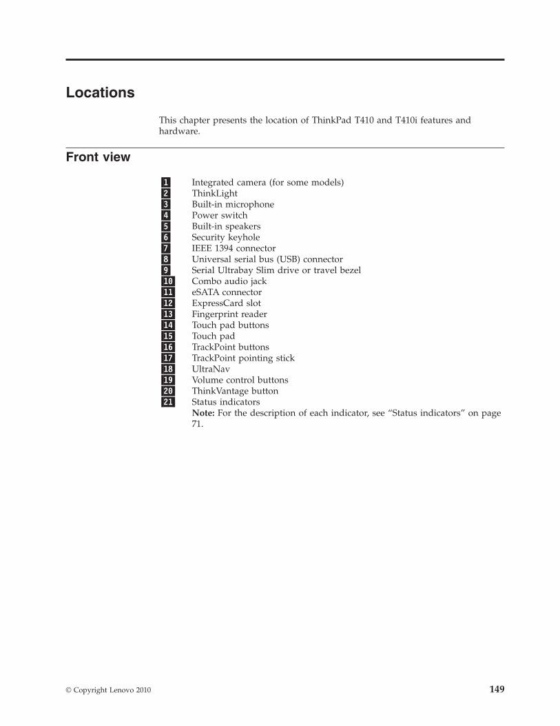
Locations
This chapter presents the location of ThinkPad T410 and T410i features andhardware.
Front view
�1� Integrated camera (for some models)�2� ThinkLight�3� Built-in microphone�4� Power switch�5� Built-in speakers�6� Security keyhole�7� IEEE 1394 connector�8� Universal serial bus (USB) connector�9� Serial Ultrabay Slim drive or travel bezel�10� Combo audio jack�11� eSATA connector�12� ExpressCard slot�13� Fingerprint reader�14� Touch pad buttons�15� Touch pad�16� TrackPoint buttons�17� TrackPoint pointing stick�18� UltraNav�19� Volume control buttons�20� ThinkVantage button�21� Status indicators
Note: For the description of each indicator, see “Status indicators” on page71.
© Copyright Lenovo 2010 149
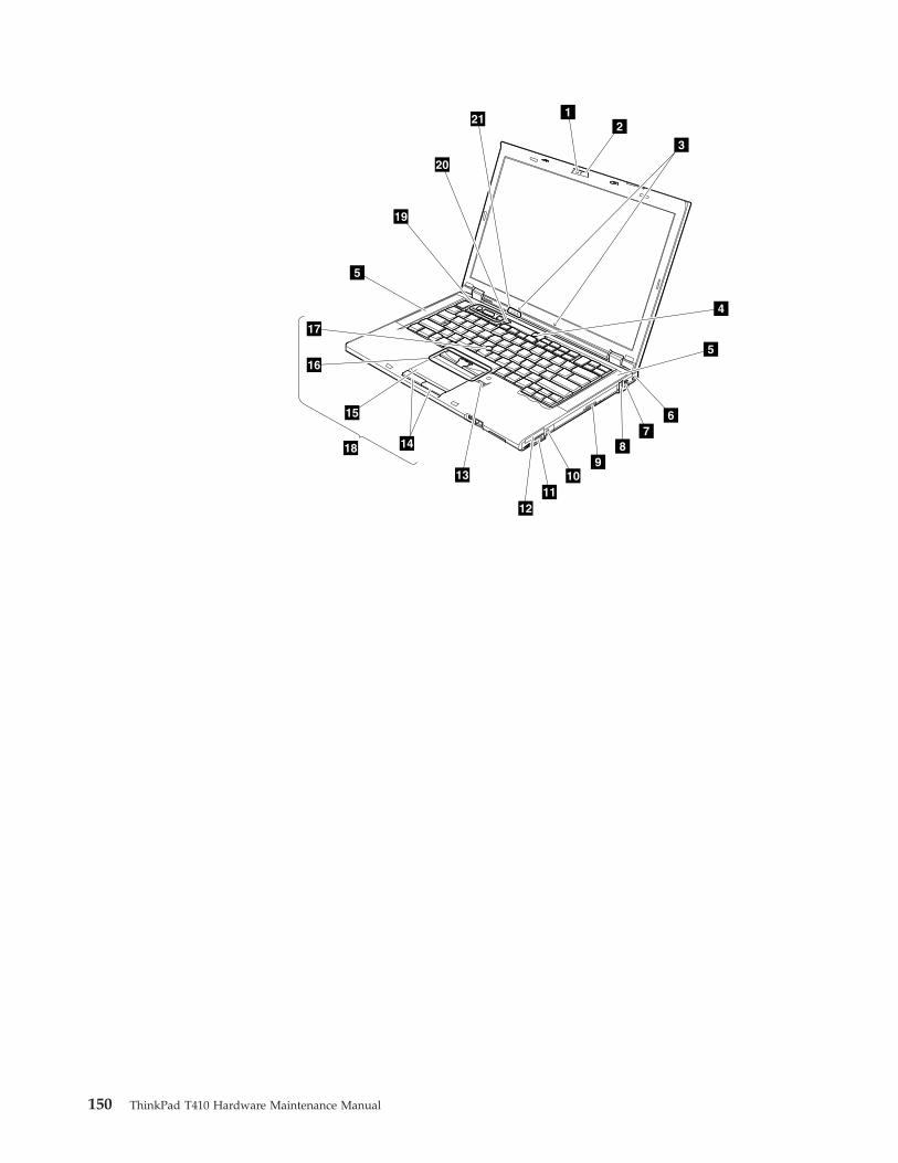
12
3
4
5
6
89
7
5
1311
12
10
15
16
17
1418
19
20
21
150 ThinkPad T410 Hardware Maintenance Manual
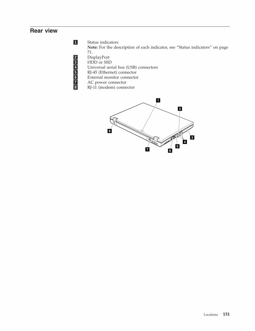
Rear view
�1� Status indicatorsNote: For the description of each indicator, see “Status indicators” on page71.
�2� DisplayPort�3� HDD or SSD�4� Universal serial bus (USB) connectors�5� RJ-45 (Ethernet) connector�6� External monitor connector�7� AC power connector�8� RJ-11 (modem) connector
1
2
45
67
8
3
Locations 151
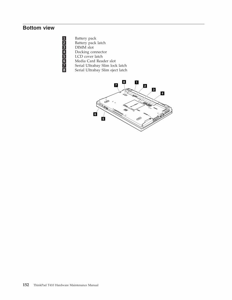
Bottom view
�1� Battery pack�2� Battery pack latch�3� DIMM slot�4� Docking connector�5� LCD cover latch�6� Media Card Reader slot�7� Serial Ultrabay Slim lock latch�8� Serial Ultrabay Slim eject latch
17
8
5
6
23
4
152 ThinkPad T410 Hardware Maintenance Manual
Parts list
This chapter contains following lists of the service parts.v “Overall” on page 154v “LCD FRUs” on page 170v “Keyboard” on page 178v “Miscellaneous parts” on page 179v “AC adapters” on page 181v “Power cords” on page 182v “Recovery discs” on page 183v “Common service tools” on page 191
Notes:v Each FRU is available for all types or models, unless specific types or models
are specified.v FRU with specific models listed and described as xxU (where U is an example
of a country designator) should be used for all models ending in U.v FRU with specific models listed and described as 3Dx (where 3D is an
example of a unique configuration) should be used for all of these models,unless specific country or region designator is specified.
v A CRU (customer replaceable unit) is identified by a single asterisk (*) or twoasterisks (**) in the CRU ID column. An N in the CRU ID column means thatthe part is not a CRU. A single asterisk (*) means that the part is a Self-serviceCRU; two asterisks (**) means that the part is an Optional-service CRU.ThinkPad Notebooks contain the following types of CRUs:Self-service CRUs
These CRUs unplug or are held by no more than two screws.Examples of these types of CRUs include an AC adapter, a powercord, a battery, and a hard disk drive. Other Self-service CRUsdepending on product design may include a memory, a wireless card,a keyboard, and a palm rest with finger print reader and touchpad.
Optional-service CRUsThese CRUs are isolated parts within the computer that are concealedby an access panel that is typically secured by more than two screws.Once the access panel is removed, the specific CRU is visible.
v FRUs marked with �OP� are available as options.
© Copyright Lenovo 2010 153
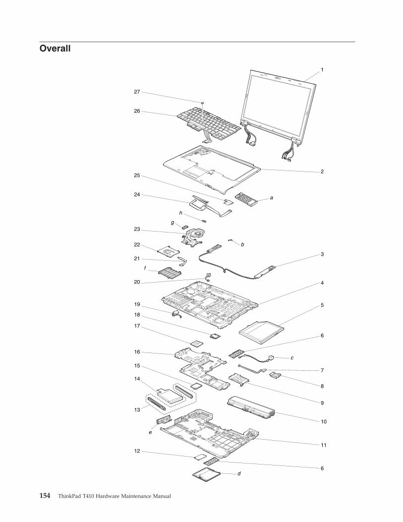
Overall
1
3
2
b
a
4
5
6
c
d
e
10
11
6
7
8
913
12
14
16
15
19
17
18
20
23g
f
h
22
21
26
27
24
25
154 ThinkPad T410 Hardware Maintenance Manual
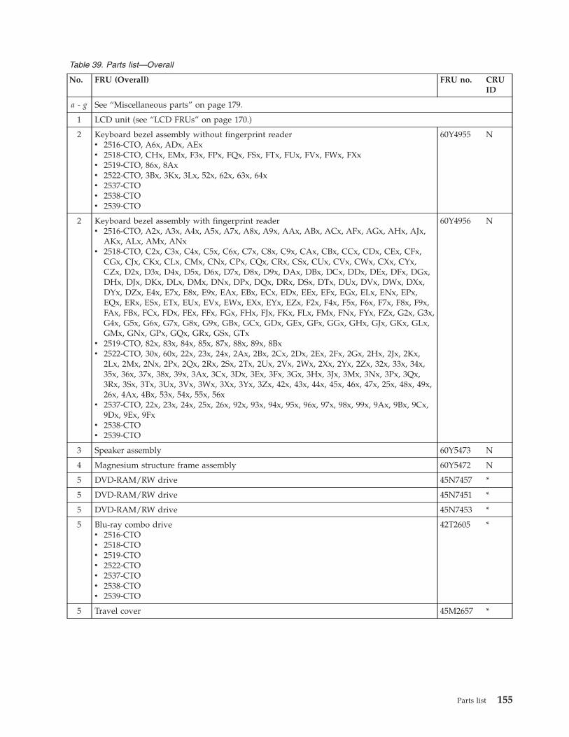
Table 39. Parts list—Overall
No. FRU (Overall) FRU no. CRUID
a - g See “Miscellaneous parts” on page 179.
1 LCD unit (see “LCD FRUs” on page 170.)
2 Keyboard bezel assembly without fingerprint readerv 2516-CTO, A6x, ADx, AExv 2518-CTO, CHx, EMx, F3x, FPx, FQx, FSx, FTx, FUx, FVx, FWx, FXxv 2519-CTO, 86x, 8Axv 2522-CTO, 3Bx, 3Kx, 3Lx, 52x, 62x, 63x, 64xv 2537-CTOv 2538-CTOv 2539-CTO
60Y4955 N
2 Keyboard bezel assembly with fingerprint readerv 2516-CTO, A2x, A3x, A4x, A5x, A7x, A8x, A9x, AAx, ABx, ACx, AFx, AGx, AHx, AJx,
AKx, ALx, AMx, ANxv 2518-CTO, C2x, C3x, C4x, C5x, C6x, C7x, C8x, C9x, CAx, CBx, CCx, CDx, CEx, CFx,
CGx, CJx, CKx, CLx, CMx, CNx, CPx, CQx, CRx, CSx, CUx, CVx, CWx, CXx, CYx,CZx, D2x, D3x, D4x, D5x, D6x, D7x, D8x, D9x, DAx, DBx, DCx, DDx, DEx, DFx, DGx,DHx, DJx, DKx, DLx, DMx, DNx, DPx, DQx, DRx, DSx, DTx, DUx, DVx, DWx, DXx,DYx, DZx, E4x, E7x, E8x, E9x, EAx, EBx, ECx, EDx, EEx, EFx, EGx, ELx, ENx, EPx,EQx, ERx, ESx, ETx, EUx, EVx, EWx, EXx, EYx, EZx, F2x, F4x, F5x, F6x, F7x, F8x, F9x,FAx, FBx, FCx, FDx, FEx, FFx, FGx, FHx, FJx, FKx, FLx, FMx, FNx, FYx, FZx, G2x, G3x,G4x, G5x, G6x, G7x, G8x, G9x, GBx, GCx, GDx, GEx, GFx, GGx, GHx, GJx, GKx, GLx,GMx, GNx, GPx, GQx, GRx, GSx, GTx
v 2519-CTO, 82x, 83x, 84x, 85x, 87x, 88x, 89x, 8Bxv 2522-CTO, 30x, 60x, 22x, 23x, 24x, 2Ax, 2Bx, 2Cx, 2Dx, 2Ex, 2Fx, 2Gx, 2Hx, 2Jx, 2Kx,
2Lx, 2Mx, 2Nx, 2Px, 2Qx, 2Rx, 2Sx, 2Tx, 2Ux, 2Vx, 2Wx, 2Xx, 2Yx, 2Zx, 32x, 33x, 34x,35x, 36x, 37x, 38x, 39x, 3Ax, 3Cx, 3Dx, 3Ex, 3Fx, 3Gx, 3Hx, 3Jx, 3Mx, 3Nx, 3Px, 3Qx,3Rx, 3Sx, 3Tx, 3Ux, 3Vx, 3Wx, 3Xx, 3Yx, 3Zx, 42x, 43x, 44x, 45x, 46x, 47x, 25x, 48x, 49x,26x, 4Ax, 4Bx, 53x, 54x, 55x, 56x
v 2537-CTO, 22x, 23x, 24x, 25x, 26x, 92x, 93x, 94x, 95x, 96x, 97x, 98x, 99x, 9Ax, 9Bx, 9Cx,9Dx, 9Ex, 9Fx
v 2538-CTOv 2539-CTO
60Y4956 N
3 Speaker assembly 60Y5473 N
4 Magnesium structure frame assembly 60Y5472 N
5 DVD-RAM/RW drive 45N7457 *
5 DVD-RAM/RW drive 45N7451 *
5 DVD-RAM/RW drive 45N7453 *
5 Blu-ray combo drivev 2516-CTOv 2518-CTOv 2519-CTOv 2522-CTOv 2537-CTOv 2538-CTOv 2539-CTO
42T2605 *
5 Travel cover 45M2657 *
Parts list 155
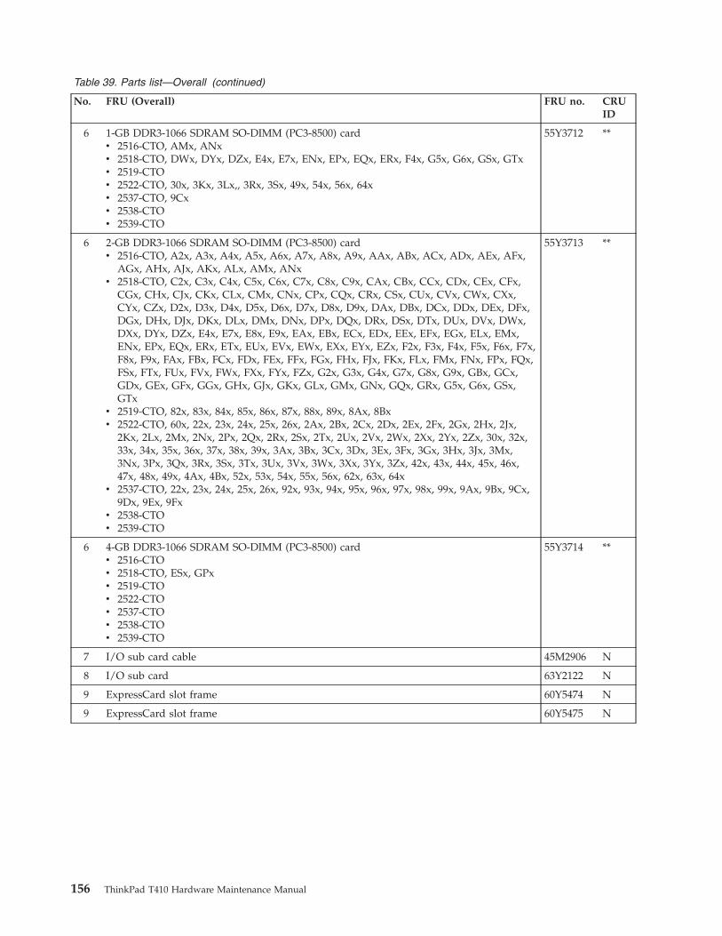
Table 39. Parts list—Overall (continued)
No. FRU (Overall) FRU no. CRUID
6 1-GB DDR3-1066 SDRAM SO-DIMM (PC3-8500) cardv 2516-CTO, AMx, ANxv 2518-CTO, DWx, DYx, DZx, E4x, E7x, ENx, EPx, EQx, ERx, F4x, G5x, G6x, GSx, GTxv 2519-CTOv 2522-CTO, 30x, 3Kx, 3Lx,, 3Rx, 3Sx, 49x, 54x, 56x, 64xv 2537-CTO, 9Cxv 2538-CTOv 2539-CTO
55Y3712 **
6 2-GB DDR3-1066 SDRAM SO-DIMM (PC3-8500) cardv 2516-CTO, A2x, A3x, A4x, A5x, A6x, A7x, A8x, A9x, AAx, ABx, ACx, ADx, AEx, AFx,
AGx, AHx, AJx, AKx, ALx, AMx, ANxv 2518-CTO, C2x, C3x, C4x, C5x, C6x, C7x, C8x, C9x, CAx, CBx, CCx, CDx, CEx, CFx,
CGx, CHx, CJx, CKx, CLx, CMx, CNx, CPx, CQx, CRx, CSx, CUx, CVx, CWx, CXx,CYx, CZx, D2x, D3x, D4x, D5x, D6x, D7x, D8x, D9x, DAx, DBx, DCx, DDx, DEx, DFx,DGx, DHx, DJx, DKx, DLx, DMx, DNx, DPx, DQx, DRx, DSx, DTx, DUx, DVx, DWx,DXx, DYx, DZx, E4x, E7x, E8x, E9x, EAx, EBx, ECx, EDx, EEx, EFx, EGx, ELx, EMx,ENx, EPx, EQx, ERx, ETx, EUx, EVx, EWx, EXx, EYx, EZx, F2x, F3x, F4x, F5x, F6x, F7x,F8x, F9x, FAx, FBx, FCx, FDx, FEx, FFx, FGx, FHx, FJx, FKx, FLx, FMx, FNx, FPx, FQx,FSx, FTx, FUx, FVx, FWx, FXx, FYx, FZx, G2x, G3x, G4x, G7x, G8x, G9x, GBx, GCx,GDx, GEx, GFx, GGx, GHx, GJx, GKx, GLx, GMx, GNx, GQx, GRx, G5x, G6x, GSx,GTx
v 2519-CTO, 82x, 83x, 84x, 85x, 86x, 87x, 88x, 89x, 8Ax, 8Bxv 2522-CTO, 60x, 22x, 23x, 24x, 25x, 26x, 2Ax, 2Bx, 2Cx, 2Dx, 2Ex, 2Fx, 2Gx, 2Hx, 2Jx,
2Kx, 2Lx, 2Mx, 2Nx, 2Px, 2Qx, 2Rx, 2Sx, 2Tx, 2Ux, 2Vx, 2Wx, 2Xx, 2Yx, 2Zx, 30x, 32x,33x, 34x, 35x, 36x, 37x, 38x, 39x, 3Ax, 3Bx, 3Cx, 3Dx, 3Ex, 3Fx, 3Gx, 3Hx, 3Jx, 3Mx,3Nx, 3Px, 3Qx, 3Rx, 3Sx, 3Tx, 3Ux, 3Vx, 3Wx, 3Xx, 3Yx, 3Zx, 42x, 43x, 44x, 45x, 46x,47x, 48x, 49x, 4Ax, 4Bx, 52x, 53x, 54x, 55x, 56x, 62x, 63x, 64x
v 2537-CTO, 22x, 23x, 24x, 25x, 26x, 92x, 93x, 94x, 95x, 96x, 97x, 98x, 99x, 9Ax, 9Bx, 9Cx,9Dx, 9Ex, 9Fx
v 2538-CTOv 2539-CTO
55Y3713 **
6 4-GB DDR3-1066 SDRAM SO-DIMM (PC3-8500) cardv 2516-CTOv 2518-CTO, ESx, GPxv 2519-CTOv 2522-CTOv 2537-CTOv 2538-CTOv 2539-CTO
55Y3714 **
7 I/O sub card cable 45M2906 N
8 I/O sub card 63Y2122 N
9 ExpressCard slot frame 60Y5474 N
9 ExpressCard slot frame 60Y5475 N
156 ThinkPad T410 Hardware Maintenance Manual
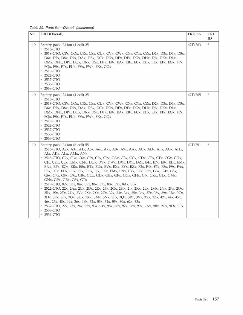
Table 39. Parts list—Overall (continued)
No. FRU (Overall) FRU no. CRUID
10 Battery pack, Li-ion (4 cell) 25v 2516-CTOv 2518-CTO, CPx, CQx, CRx, CSx, CUx, CVx, CWx, CXx, CYx, CZx, D2x, D3x, D4x, D5x,
D6x, D7x, D8x, D9x, DAx, DBx, DCx, DDx, DEx, DFx, DGx, DHx, DJx, DKx, DLx,DMx, DNx, DPx, DQx, DRx, DSx, DTx, E9x, EAx, EBx, ECx, EDx, EEx, EFx, EGx, FPx,FQx, FSx, FTx, FUx, FVx, FWx, FXx, GQx
v 2519-CTOv 2522-CTOv 2537-CTOv 2538-CTOv 2539-CTO
42T4763 *
10 Battery pack, Li-ion (4 cell) 25v 2516-CTOv 2518-CTO, CPx, CQx, CRx, CSx, CUx, CVx, CWx, CXx, CYx, CZx, D2x, D3x, D4x, D5x,
D6x, D7x, D8x, D9x, DAx, DBx, DCx, DDx, DEx, DFx, DGx, DHx, DJx, DKx, DLx,DMx, DNx, DPx, DQx, DRx, DSx, DTx, E9x, EAx, EBx, ECx, EDx, EEx, EFx, EGx, FPx,FQx, FSx, FTx, FUx, FVx, FWx, FXx, GQx
v 2519-CTOv 2522-CTOv 2537-CTOv 2538-CTOv 2539-CTO
42T4765 *
10 Battery pack, Li-ion (6 cell) 55+v 2516-CTO, A2x, A3x, A4x, A5x, A6x, A7x, A8x, A9x, AAx, ACx, ADx, AFx, AGx, AHx,
AJx, AKx, ALx, AMx, ANxv 2518-CTO, C2x, C3x, C6x, C7x, C8x, C9x, CAx, CBx, CCx, CDx, CEx, CFx, CGx, CHx,
CJx, CKx, CLx, CMx, CNx, DUx, DVx, DWx, DXx, DYx, DZx, E4x, E7x, E8x, ELx, EMx,ENx, EPx, EQx, ERx, ESx, ETx, EUx, EVx, EXx, EYx, EZx, F3x, F4x, F7x, F8x, F9x, FAx,FBx, FCx, FDx, FEx, FFx, FHx, FJx, FKx, FMx, FNx, FYx, FZx, G2x, G3x, G4x, G5x,G6x, G7x, G8x, G9x, GBx, GCx, GDx, GEx, GFx, GGx, GHx, GJx, GKx, GLx, GMx,GNx, GPx, GRx, GSx, GTx
v 2519-CTO, 82x, 83x, 84x, 85x, 86x, 87x, 88x, 89x, 8Ax, 8Bxv 2522-CTO, 22x, 2Ax, 2Cx, 2Dx, 2Ex, 2Fx, 2Gx, 2Hx, 2Jx, 2Kx, 2Lx, 2Mx, 2Nx, 2Px, 2Qx,
2Rx, 2Sx, 2Tx, 2Ux, 2Vx, 2Xx, 2Yx, 2Zx, 32x, 33x, 34x, 35x, 36x, 37x, 38x, 39x, 3Bx, 3Cx,3Dx, 3Ex, 3Fx, 3Gx, 3Hx, 3Kx, 3Mx, 3Nx, 3Px, 3Qx, 3Rx, 3Vx, 3Yx, 3Zx, 42x, 44x, 45x,46x, 25x, 48x, 49x, 26x, 4Bx, 52x, 53x, 54x, 55x, 60x, 62x, 63x
v 2537-CTO, 22x, 25x, 26x, 92x, 93x, 94x, 95x, 96x, 97x, 98x, 99x, 9Ax, 9Bx, 9Cx, 9Dx, 9Fxv 2538-CTOv 2539-CTO
42T4791 *
Parts list 157
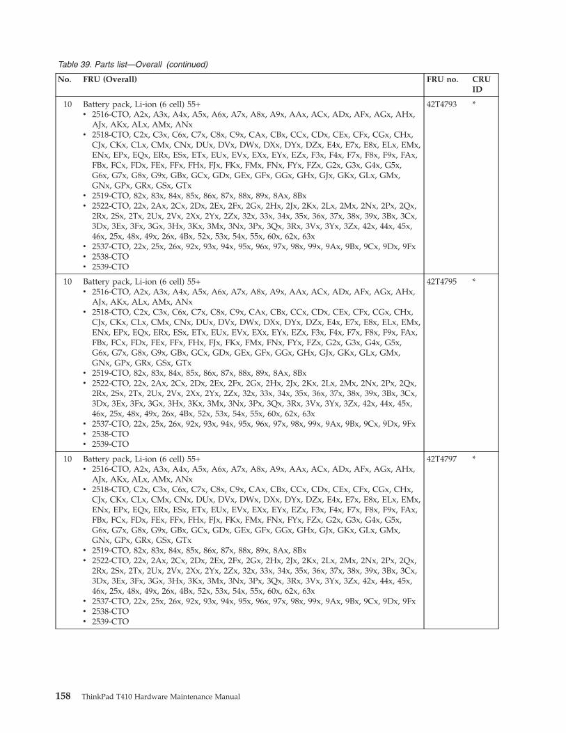
Table 39. Parts list—Overall (continued)
No. FRU (Overall) FRU no. CRUID
10 Battery pack, Li-ion (6 cell) 55+v 2516-CTO, A2x, A3x, A4x, A5x, A6x, A7x, A8x, A9x, AAx, ACx, ADx, AFx, AGx, AHx,
AJx, AKx, ALx, AMx, ANxv 2518-CTO, C2x, C3x, C6x, C7x, C8x, C9x, CAx, CBx, CCx, CDx, CEx, CFx, CGx, CHx,
CJx, CKx, CLx, CMx, CNx, DUx, DVx, DWx, DXx, DYx, DZx, E4x, E7x, E8x, ELx, EMx,ENx, EPx, EQx, ERx, ESx, ETx, EUx, EVx, EXx, EYx, EZx, F3x, F4x, F7x, F8x, F9x, FAx,FBx, FCx, FDx, FEx, FFx, FHx, FJx, FKx, FMx, FNx, FYx, FZx, G2x, G3x, G4x, G5x,G6x, G7x, G8x, G9x, GBx, GCx, GDx, GEx, GFx, GGx, GHx, GJx, GKx, GLx, GMx,GNx, GPx, GRx, GSx, GTx
v 2519-CTO, 82x, 83x, 84x, 85x, 86x, 87x, 88x, 89x, 8Ax, 8Bxv 2522-CTO, 22x, 2Ax, 2Cx, 2Dx, 2Ex, 2Fx, 2Gx, 2Hx, 2Jx, 2Kx, 2Lx, 2Mx, 2Nx, 2Px, 2Qx,
2Rx, 2Sx, 2Tx, 2Ux, 2Vx, 2Xx, 2Yx, 2Zx, 32x, 33x, 34x, 35x, 36x, 37x, 38x, 39x, 3Bx, 3Cx,3Dx, 3Ex, 3Fx, 3Gx, 3Hx, 3Kx, 3Mx, 3Nx, 3Px, 3Qx, 3Rx, 3Vx, 3Yx, 3Zx, 42x, 44x, 45x,46x, 25x, 48x, 49x, 26x, 4Bx, 52x, 53x, 54x, 55x, 60x, 62x, 63x
v 2537-CTO, 22x, 25x, 26x, 92x, 93x, 94x, 95x, 96x, 97x, 98x, 99x, 9Ax, 9Bx, 9Cx, 9Dx, 9Fxv 2538-CTOv 2539-CTO
42T4793 *
10 Battery pack, Li-ion (6 cell) 55+v 2516-CTO, A2x, A3x, A4x, A5x, A6x, A7x, A8x, A9x, AAx, ACx, ADx, AFx, AGx, AHx,
AJx, AKx, ALx, AMx, ANxv 2518-CTO, C2x, C3x, C6x, C7x, C8x, C9x, CAx, CBx, CCx, CDx, CEx, CFx, CGx, CHx,
CJx, CKx, CLx, CMx, CNx, DUx, DVx, DWx, DXx, DYx, DZx, E4x, E7x, E8x, ELx, EMx,ENx, EPx, EQx, ERx, ESx, ETx, EUx, EVx, EXx, EYx, EZx, F3x, F4x, F7x, F8x, F9x, FAx,FBx, FCx, FDx, FEx, FFx, FHx, FJx, FKx, FMx, FNx, FYx, FZx, G2x, G3x, G4x, G5x,G6x, G7x, G8x, G9x, GBx, GCx, GDx, GEx, GFx, GGx, GHx, GJx, GKx, GLx, GMx,GNx, GPx, GRx, GSx, GTx
v 2519-CTO, 82x, 83x, 84x, 85x, 86x, 87x, 88x, 89x, 8Ax, 8Bxv 2522-CTO, 22x, 2Ax, 2Cx, 2Dx, 2Ex, 2Fx, 2Gx, 2Hx, 2Jx, 2Kx, 2Lx, 2Mx, 2Nx, 2Px, 2Qx,
2Rx, 2Sx, 2Tx, 2Ux, 2Vx, 2Xx, 2Yx, 2Zx, 32x, 33x, 34x, 35x, 36x, 37x, 38x, 39x, 3Bx, 3Cx,3Dx, 3Ex, 3Fx, 3Gx, 3Hx, 3Kx, 3Mx, 3Nx, 3Px, 3Qx, 3Rx, 3Vx, 3Yx, 3Zx, 42x, 44x, 45x,46x, 25x, 48x, 49x, 26x, 4Bx, 52x, 53x, 54x, 55x, 60x, 62x, 63x
v 2537-CTO, 22x, 25x, 26x, 92x, 93x, 94x, 95x, 96x, 97x, 98x, 99x, 9Ax, 9Bx, 9Cx, 9Dx, 9Fxv 2538-CTOv 2539-CTO
42T4795 *
10 Battery pack, Li-ion (6 cell) 55+v 2516-CTO, A2x, A3x, A4x, A5x, A6x, A7x, A8x, A9x, AAx, ACx, ADx, AFx, AGx, AHx,
AJx, AKx, ALx, AMx, ANxv 2518-CTO, C2x, C3x, C6x, C7x, C8x, C9x, CAx, CBx, CCx, CDx, CEx, CFx, CGx, CHx,
CJx, CKx, CLx, CMx, CNx, DUx, DVx, DWx, DXx, DYx, DZx, E4x, E7x, E8x, ELx, EMx,ENx, EPx, EQx, ERx, ESx, ETx, EUx, EVx, EXx, EYx, EZx, F3x, F4x, F7x, F8x, F9x, FAx,FBx, FCx, FDx, FEx, FFx, FHx, FJx, FKx, FMx, FNx, FYx, FZx, G2x, G3x, G4x, G5x,G6x, G7x, G8x, G9x, GBx, GCx, GDx, GEx, GFx, GGx, GHx, GJx, GKx, GLx, GMx,GNx, GPx, GRx, GSx, GTx
v 2519-CTO, 82x, 83x, 84x, 85x, 86x, 87x, 88x, 89x, 8Ax, 8Bxv 2522-CTO, 22x, 2Ax, 2Cx, 2Dx, 2Ex, 2Fx, 2Gx, 2Hx, 2Jx, 2Kx, 2Lx, 2Mx, 2Nx, 2Px, 2Qx,
2Rx, 2Sx, 2Tx, 2Ux, 2Vx, 2Xx, 2Yx, 2Zx, 32x, 33x, 34x, 35x, 36x, 37x, 38x, 39x, 3Bx, 3Cx,3Dx, 3Ex, 3Fx, 3Gx, 3Hx, 3Kx, 3Mx, 3Nx, 3Px, 3Qx, 3Rx, 3Vx, 3Yx, 3Zx, 42x, 44x, 45x,46x, 25x, 48x, 49x, 26x, 4Bx, 52x, 53x, 54x, 55x, 60x, 62x, 63x
v 2537-CTO, 22x, 25x, 26x, 92x, 93x, 94x, 95x, 96x, 97x, 98x, 99x, 9Ax, 9Bx, 9Cx, 9Dx, 9Fxv 2538-CTOv 2539-CTO
42T4797 *
158 ThinkPad T410 Hardware Maintenance Manual
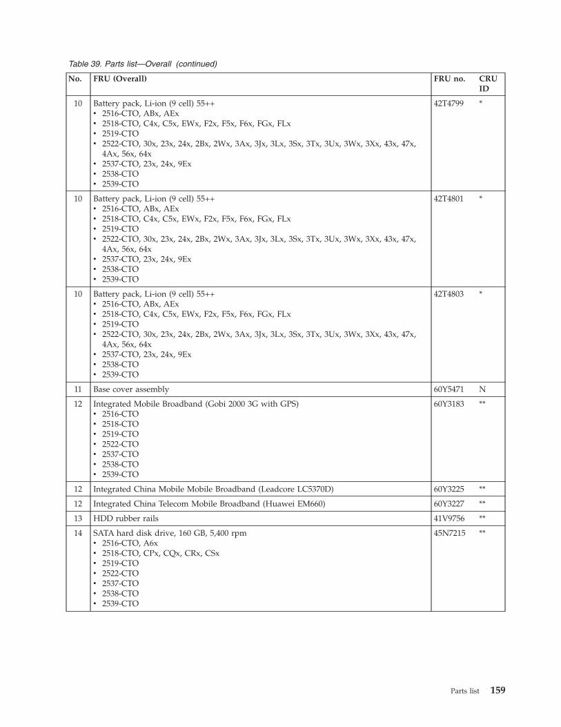
Table 39. Parts list—Overall (continued)
No. FRU (Overall) FRU no. CRUID
10 Battery pack, Li-ion (9 cell) 55++v 2516-CTO, ABx, AExv 2518-CTO, C4x, C5x, EWx, F2x, F5x, F6x, FGx, FLxv 2519-CTOv 2522-CTO, 30x, 23x, 24x, 2Bx, 2Wx, 3Ax, 3Jx, 3Lx, 3Sx, 3Tx, 3Ux, 3Wx, 3Xx, 43x, 47x,
4Ax, 56x, 64xv 2537-CTO, 23x, 24x, 9Exv 2538-CTOv 2539-CTO
42T4799 *
10 Battery pack, Li-ion (9 cell) 55++v 2516-CTO, ABx, AExv 2518-CTO, C4x, C5x, EWx, F2x, F5x, F6x, FGx, FLxv 2519-CTOv 2522-CTO, 30x, 23x, 24x, 2Bx, 2Wx, 3Ax, 3Jx, 3Lx, 3Sx, 3Tx, 3Ux, 3Wx, 3Xx, 43x, 47x,
4Ax, 56x, 64xv 2537-CTO, 23x, 24x, 9Exv 2538-CTOv 2539-CTO
42T4801 *
10 Battery pack, Li-ion (9 cell) 55++v 2516-CTO, ABx, AExv 2518-CTO, C4x, C5x, EWx, F2x, F5x, F6x, FGx, FLxv 2519-CTOv 2522-CTO, 30x, 23x, 24x, 2Bx, 2Wx, 3Ax, 3Jx, 3Lx, 3Sx, 3Tx, 3Ux, 3Wx, 3Xx, 43x, 47x,
4Ax, 56x, 64xv 2537-CTO, 23x, 24x, 9Exv 2538-CTOv 2539-CTO
42T4803 *
11 Base cover assembly 60Y5471 N
12 Integrated Mobile Broadband (Gobi 2000 3G with GPS)v 2516-CTOv 2518-CTOv 2519-CTOv 2522-CTOv 2537-CTOv 2538-CTOv 2539-CTO
60Y3183 **
12 Integrated China Mobile Mobile Broadband (Leadcore LC5370D) 60Y3225 **
12 Integrated China Telecom Mobile Broadband (Huawei EM660) 60Y3227 **
13 HDD rubber rails 41V9756 **
14 SATA hard disk drive, 160 GB, 5,400 rpmv 2516-CTO, A6xv 2518-CTO, CPx, CQx, CRx, CSxv 2519-CTOv 2522-CTOv 2537-CTOv 2538-CTOv 2539-CTO
45N7215 **
Parts list 159
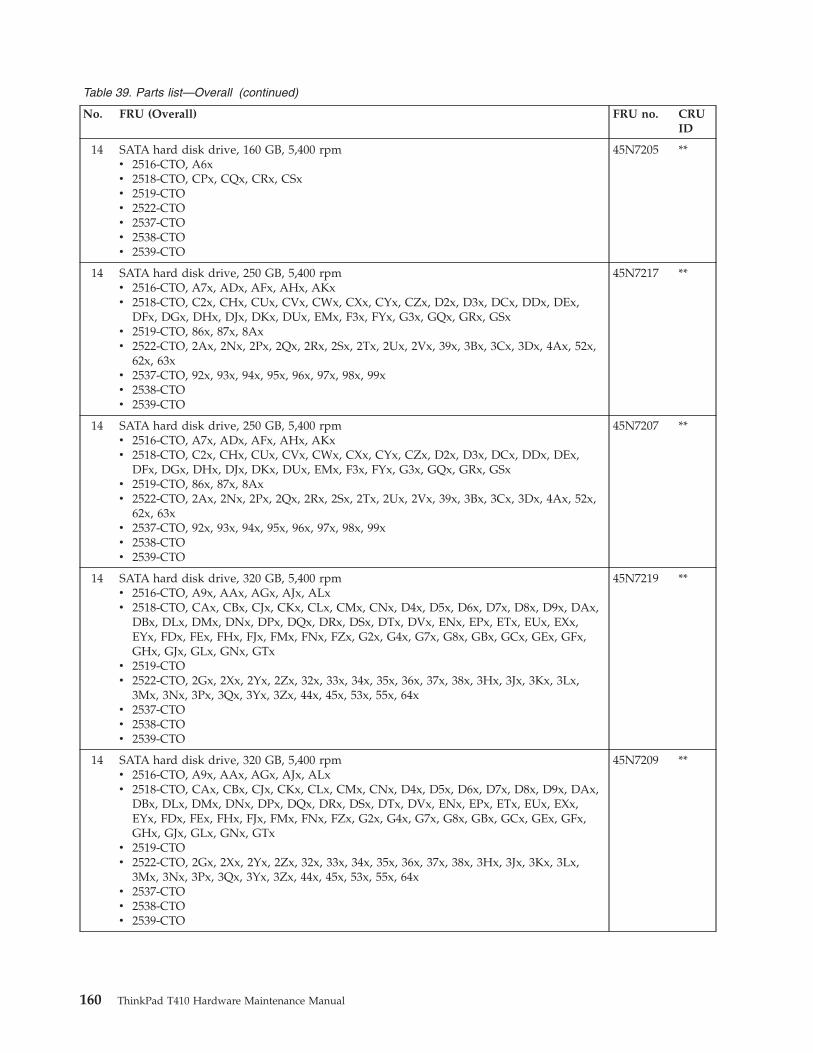
Table 39. Parts list—Overall (continued)
No. FRU (Overall) FRU no. CRUID
14 SATA hard disk drive, 160 GB, 5,400 rpmv 2516-CTO, A6xv 2518-CTO, CPx, CQx, CRx, CSxv 2519-CTOv 2522-CTOv 2537-CTOv 2538-CTOv 2539-CTO
45N7205 **
14 SATA hard disk drive, 250 GB, 5,400 rpmv 2516-CTO, A7x, ADx, AFx, AHx, AKxv 2518-CTO, C2x, CHx, CUx, CVx, CWx, CXx, CYx, CZx, D2x, D3x, DCx, DDx, DEx,
DFx, DGx, DHx, DJx, DKx, DUx, EMx, F3x, FYx, G3x, GQx, GRx, GSxv 2519-CTO, 86x, 87x, 8Axv 2522-CTO, 2Ax, 2Nx, 2Px, 2Qx, 2Rx, 2Sx, 2Tx, 2Ux, 2Vx, 39x, 3Bx, 3Cx, 3Dx, 4Ax, 52x,
62x, 63xv 2537-CTO, 92x, 93x, 94x, 95x, 96x, 97x, 98x, 99xv 2538-CTOv 2539-CTO
45N7217 **
14 SATA hard disk drive, 250 GB, 5,400 rpmv 2516-CTO, A7x, ADx, AFx, AHx, AKxv 2518-CTO, C2x, CHx, CUx, CVx, CWx, CXx, CYx, CZx, D2x, D3x, DCx, DDx, DEx,
DFx, DGx, DHx, DJx, DKx, DUx, EMx, F3x, FYx, G3x, GQx, GRx, GSxv 2519-CTO, 86x, 87x, 8Axv 2522-CTO, 2Ax, 2Nx, 2Px, 2Qx, 2Rx, 2Sx, 2Tx, 2Ux, 2Vx, 39x, 3Bx, 3Cx, 3Dx, 4Ax, 52x,
62x, 63xv 2537-CTO, 92x, 93x, 94x, 95x, 96x, 97x, 98x, 99xv 2538-CTOv 2539-CTO
45N7207 **
14 SATA hard disk drive, 320 GB, 5,400 rpmv 2516-CTO, A9x, AAx, AGx, AJx, ALxv 2518-CTO, CAx, CBx, CJx, CKx, CLx, CMx, CNx, D4x, D5x, D6x, D7x, D8x, D9x, DAx,
DBx, DLx, DMx, DNx, DPx, DQx, DRx, DSx, DTx, DVx, ENx, EPx, ETx, EUx, EXx,EYx, FDx, FEx, FHx, FJx, FMx, FNx, FZx, G2x, G4x, G7x, G8x, GBx, GCx, GEx, GFx,GHx, GJx, GLx, GNx, GTx
v 2519-CTOv 2522-CTO, 2Gx, 2Xx, 2Yx, 2Zx, 32x, 33x, 34x, 35x, 36x, 37x, 38x, 3Hx, 3Jx, 3Kx, 3Lx,
3Mx, 3Nx, 3Px, 3Qx, 3Yx, 3Zx, 44x, 45x, 53x, 55x, 64xv 2537-CTOv 2538-CTOv 2539-CTO
45N7219 **
14 SATA hard disk drive, 320 GB, 5,400 rpmv 2516-CTO, A9x, AAx, AGx, AJx, ALxv 2518-CTO, CAx, CBx, CJx, CKx, CLx, CMx, CNx, D4x, D5x, D6x, D7x, D8x, D9x, DAx,
DBx, DLx, DMx, DNx, DPx, DQx, DRx, DSx, DTx, DVx, ENx, EPx, ETx, EUx, EXx,EYx, FDx, FEx, FHx, FJx, FMx, FNx, FZx, G2x, G4x, G7x, G8x, GBx, GCx, GEx, GFx,GHx, GJx, GLx, GNx, GTx
v 2519-CTOv 2522-CTO, 2Gx, 2Xx, 2Yx, 2Zx, 32x, 33x, 34x, 35x, 36x, 37x, 38x, 3Hx, 3Jx, 3Kx, 3Lx,
3Mx, 3Nx, 3Px, 3Qx, 3Yx, 3Zx, 44x, 45x, 53x, 55x, 64xv 2537-CTOv 2538-CTOv 2539-CTO
45N7209 **
160 ThinkPad T410 Hardware Maintenance Manual
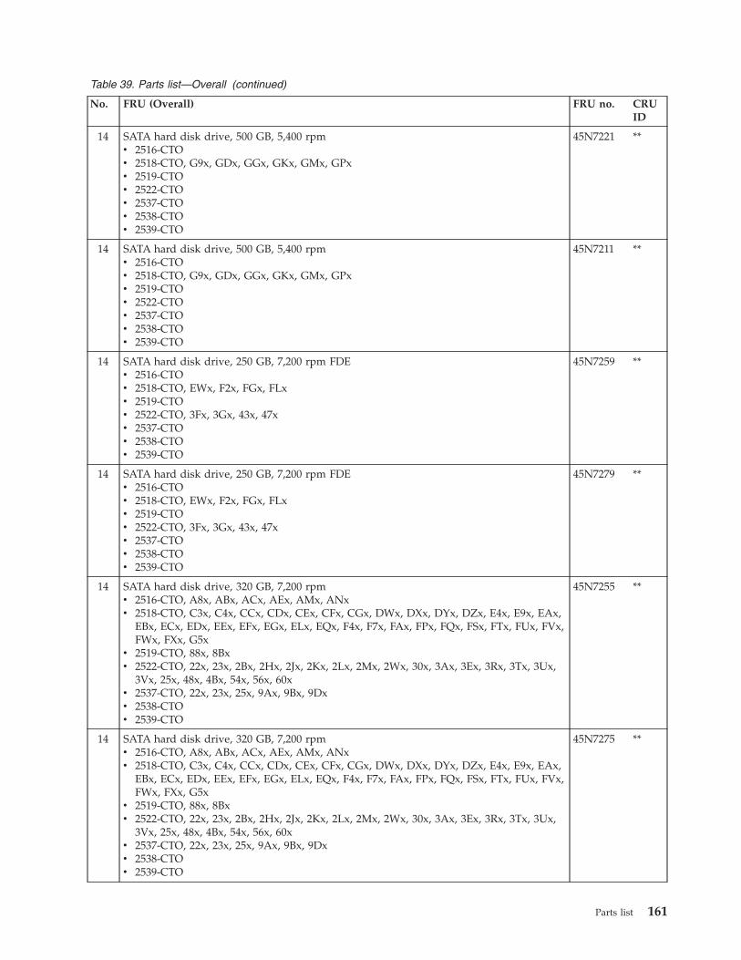
Table 39. Parts list—Overall (continued)
No. FRU (Overall) FRU no. CRUID
14 SATA hard disk drive, 500 GB, 5,400 rpmv 2516-CTOv 2518-CTO, G9x, GDx, GGx, GKx, GMx, GPxv 2519-CTOv 2522-CTOv 2537-CTOv 2538-CTOv 2539-CTO
45N7221 **
14 SATA hard disk drive, 500 GB, 5,400 rpmv 2516-CTOv 2518-CTO, G9x, GDx, GGx, GKx, GMx, GPxv 2519-CTOv 2522-CTOv 2537-CTOv 2538-CTOv 2539-CTO
45N7211 **
14 SATA hard disk drive, 250 GB, 7,200 rpm FDEv 2516-CTOv 2518-CTO, EWx, F2x, FGx, FLxv 2519-CTOv 2522-CTO, 3Fx, 3Gx, 43x, 47xv 2537-CTOv 2538-CTOv 2539-CTO
45N7259 **
14 SATA hard disk drive, 250 GB, 7,200 rpm FDEv 2516-CTOv 2518-CTO, EWx, F2x, FGx, FLxv 2519-CTOv 2522-CTO, 3Fx, 3Gx, 43x, 47xv 2537-CTOv 2538-CTOv 2539-CTO
45N7279 **
14 SATA hard disk drive, 320 GB, 7,200 rpmv 2516-CTO, A8x, ABx, ACx, AEx, AMx, ANxv 2518-CTO, C3x, C4x, CCx, CDx, CEx, CFx, CGx, DWx, DXx, DYx, DZx, E4x, E9x, EAx,
EBx, ECx, EDx, EEx, EFx, EGx, ELx, EQx, F4x, F7x, FAx, FPx, FQx, FSx, FTx, FUx, FVx,FWx, FXx, G5x
v 2519-CTO, 88x, 8Bxv 2522-CTO, 22x, 23x, 2Bx, 2Hx, 2Jx, 2Kx, 2Lx, 2Mx, 2Wx, 30x, 3Ax, 3Ex, 3Rx, 3Tx, 3Ux,
3Vx, 25x, 48x, 4Bx, 54x, 56x, 60xv 2537-CTO, 22x, 23x, 25x, 9Ax, 9Bx, 9Dxv 2538-CTOv 2539-CTO
45N7255 **
14 SATA hard disk drive, 320 GB, 7,200 rpmv 2516-CTO, A8x, ABx, ACx, AEx, AMx, ANxv 2518-CTO, C3x, C4x, CCx, CDx, CEx, CFx, CGx, DWx, DXx, DYx, DZx, E4x, E9x, EAx,
EBx, ECx, EDx, EEx, EFx, EGx, ELx, EQx, F4x, F7x, FAx, FPx, FQx, FSx, FTx, FUx, FVx,FWx, FXx, G5x
v 2519-CTO, 88x, 8Bxv 2522-CTO, 22x, 23x, 2Bx, 2Hx, 2Jx, 2Kx, 2Lx, 2Mx, 2Wx, 30x, 3Ax, 3Ex, 3Rx, 3Tx, 3Ux,
3Vx, 25x, 48x, 4Bx, 54x, 56x, 60xv 2537-CTO, 22x, 23x, 25x, 9Ax, 9Bx, 9Dxv 2538-CTOv 2539-CTO
45N7275 **
Parts list 161
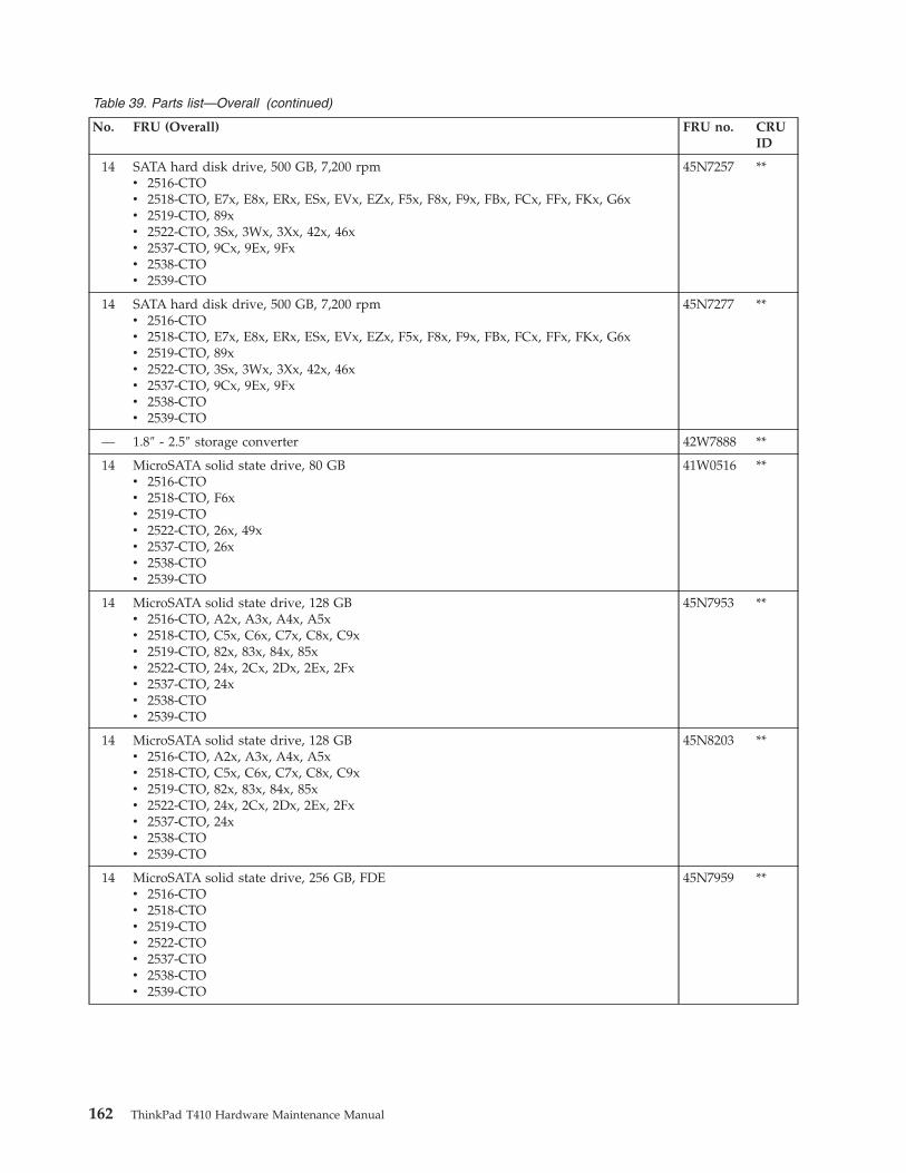
Table 39. Parts list—Overall (continued)
No. FRU (Overall) FRU no. CRUID
14 SATA hard disk drive, 500 GB, 7,200 rpmv 2516-CTOv 2518-CTO, E7x, E8x, ERx, ESx, EVx, EZx, F5x, F8x, F9x, FBx, FCx, FFx, FKx, G6xv 2519-CTO, 89xv 2522-CTO, 3Sx, 3Wx, 3Xx, 42x, 46xv 2537-CTO, 9Cx, 9Ex, 9Fxv 2538-CTOv 2539-CTO
45N7257 **
14 SATA hard disk drive, 500 GB, 7,200 rpmv 2516-CTOv 2518-CTO, E7x, E8x, ERx, ESx, EVx, EZx, F5x, F8x, F9x, FBx, FCx, FFx, FKx, G6xv 2519-CTO, 89xv 2522-CTO, 3Sx, 3Wx, 3Xx, 42x, 46xv 2537-CTO, 9Cx, 9Ex, 9Fxv 2538-CTOv 2539-CTO
45N7277 **
— 1.8″ - 2.5″ storage converter 42W7888 **
14 MicroSATA solid state drive, 80 GBv 2516-CTOv 2518-CTO, F6xv 2519-CTOv 2522-CTO, 26x, 49xv 2537-CTO, 26xv 2538-CTOv 2539-CTO
41W0516 **
14 MicroSATA solid state drive, 128 GBv 2516-CTO, A2x, A3x, A4x, A5xv 2518-CTO, C5x, C6x, C7x, C8x, C9xv 2519-CTO, 82x, 83x, 84x, 85xv 2522-CTO, 24x, 2Cx, 2Dx, 2Ex, 2Fxv 2537-CTO, 24xv 2538-CTOv 2539-CTO
45N7953 **
14 MicroSATA solid state drive, 128 GBv 2516-CTO, A2x, A3x, A4x, A5xv 2518-CTO, C5x, C6x, C7x, C8x, C9xv 2519-CTO, 82x, 83x, 84x, 85xv 2522-CTO, 24x, 2Cx, 2Dx, 2Ex, 2Fxv 2537-CTO, 24xv 2538-CTOv 2539-CTO
45N8203 **
14 MicroSATA solid state drive, 256 GB, FDEv 2516-CTOv 2518-CTOv 2519-CTOv 2522-CTOv 2537-CTOv 2538-CTOv 2539-CTO
45N7959 **
162 ThinkPad T410 Hardware Maintenance Manual
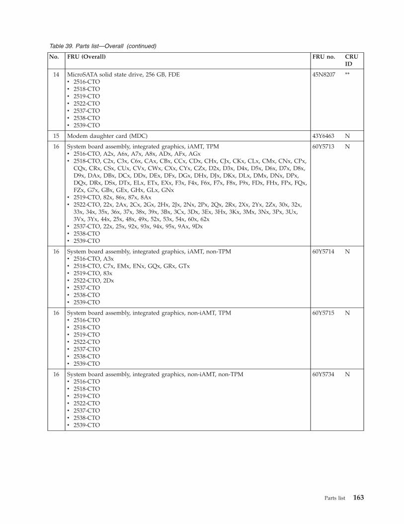
Table 39. Parts list—Overall (continued)
No. FRU (Overall) FRU no. CRUID
14 MicroSATA solid state drive, 256 GB, FDEv 2516-CTOv 2518-CTOv 2519-CTOv 2522-CTOv 2537-CTOv 2538-CTOv 2539-CTO
45N8207 **
15 Modem daughter card (MDC) 43Y6463 N
16 System board assembly, integrated graphics, iAMT, TPMv 2516-CTO, A2x, A6x, A7x, A8x, ADx, AFx, AGxv 2518-CTO, C2x, C3x, C6x, CAx, CBx, CCx, CDx, CHx, CJx, CKx, CLx, CMx, CNx, CPx,
CQx, CRx, CSx, CUx, CVx, CWx, CXx, CYx, CZx, D2x, D3x, D4x, D5x, D6x, D7x, D8x,D9x, DAx, DBx, DCx, DDx, DEx, DFx, DGx, DHx, DJx, DKx, DLx, DMx, DNx, DPx,DQx, DRx, DSx, DTx, ELx, ETx, EXx, F3x, F4x, F6x, F7x, F8x, F9x, FDx, FHx, FPx, FQx,FZx, G7x, GBx, GEx, GHx, GLx, GNx
v 2519-CTO, 82x, 86x, 87x, 8Axv 2522-CTO, 22x, 2Ax, 2Cx, 2Gx, 2Hx, 2Jx, 2Nx, 2Px, 2Qx, 2Rx, 2Xx, 2Yx, 2Zx, 30x, 32x,
33x, 34x, 35x, 36x, 37x, 38x, 39x, 3Bx, 3Cx, 3Dx, 3Ex, 3Hx, 3Kx, 3Mx, 3Nx, 3Px, 3Ux,3Vx, 3Yx, 44x, 25x, 48x, 49x, 52x, 53x, 54x, 60x, 62x
v 2537-CTO, 22x, 25x, 92x, 93x, 94x, 95x, 9Ax, 9Dxv 2538-CTOv 2539-CTO
60Y5713 N
16 System board assembly, integrated graphics, iAMT, non-TPMv 2516-CTO, A3xv 2518-CTO, C7x, EMx, ENx, GQx, GRx, GTxv 2519-CTO, 83xv 2522-CTO, 2Dxv 2537-CTOv 2538-CTOv 2539-CTO
60Y5714 N
16 System board assembly, integrated graphics, non-iAMT, TPMv 2516-CTOv 2518-CTOv 2519-CTOv 2522-CTOv 2537-CTOv 2538-CTOv 2539-CTO
60Y5715 N
16 System board assembly, integrated graphics, non-iAMT, non-TPMv 2516-CTOv 2518-CTOv 2519-CTOv 2522-CTOv 2537-CTOv 2538-CTOv 2539-CTO
60Y5734 N
Parts list 163
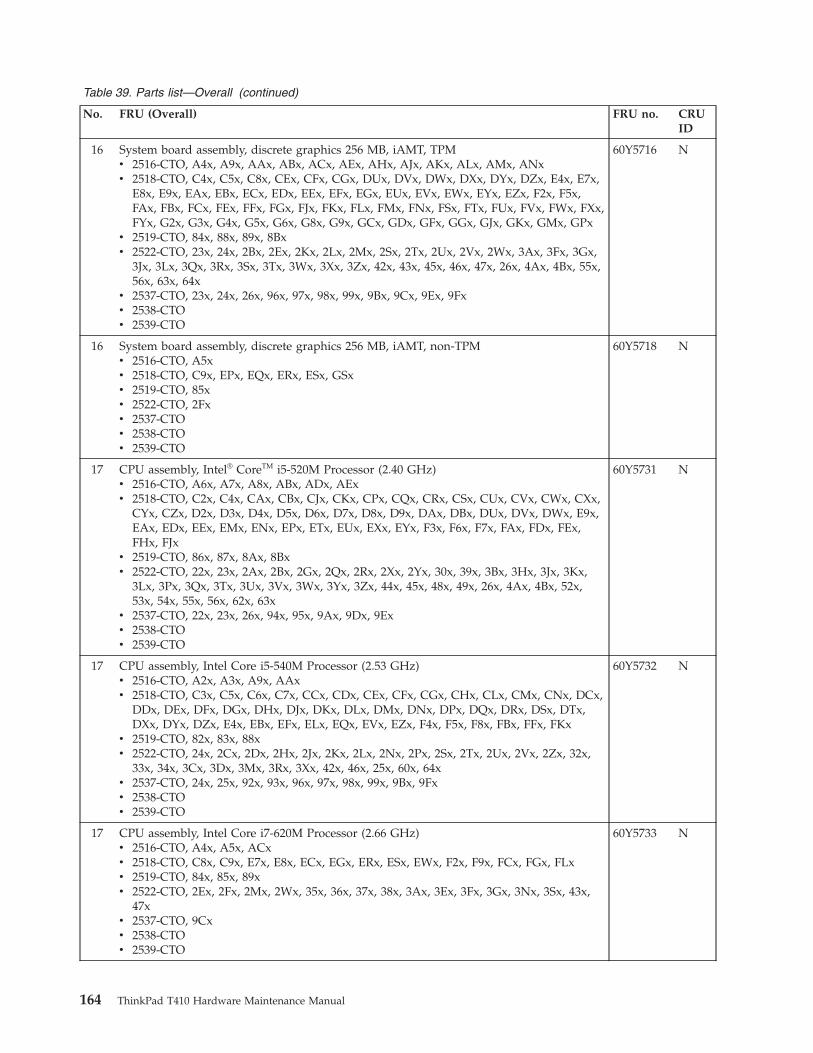
Table 39. Parts list—Overall (continued)
No. FRU (Overall) FRU no. CRUID
16 System board assembly, discrete graphics 256 MB, iAMT, TPMv 2516-CTO, A4x, A9x, AAx, ABx, ACx, AEx, AHx, AJx, AKx, ALx, AMx, ANxv 2518-CTO, C4x, C5x, C8x, CEx, CFx, CGx, DUx, DVx, DWx, DXx, DYx, DZx, E4x, E7x,
E8x, E9x, EAx, EBx, ECx, EDx, EEx, EFx, EGx, EUx, EVx, EWx, EYx, EZx, F2x, F5x,FAx, FBx, FCx, FEx, FFx, FGx, FJx, FKx, FLx, FMx, FNx, FSx, FTx, FUx, FVx, FWx, FXx,FYx, G2x, G3x, G4x, G5x, G6x, G8x, G9x, GCx, GDx, GFx, GGx, GJx, GKx, GMx, GPx
v 2519-CTO, 84x, 88x, 89x, 8Bxv 2522-CTO, 23x, 24x, 2Bx, 2Ex, 2Kx, 2Lx, 2Mx, 2Sx, 2Tx, 2Ux, 2Vx, 2Wx, 3Ax, 3Fx, 3Gx,
3Jx, 3Lx, 3Qx, 3Rx, 3Sx, 3Tx, 3Wx, 3Xx, 3Zx, 42x, 43x, 45x, 46x, 47x, 26x, 4Ax, 4Bx, 55x,56x, 63x, 64x
v 2537-CTO, 23x, 24x, 26x, 96x, 97x, 98x, 99x, 9Bx, 9Cx, 9Ex, 9Fxv 2538-CTOv 2539-CTO
60Y5716 N
16 System board assembly, discrete graphics 256 MB, iAMT, non-TPMv 2516-CTO, A5xv 2518-CTO, C9x, EPx, EQx, ERx, ESx, GSxv 2519-CTO, 85xv 2522-CTO, 2Fxv 2537-CTOv 2538-CTOv 2539-CTO
60Y5718 N
17 CPU assembly, Intel® CoreTM i5-520M Processor (2.40 GHz)v 2516-CTO, A6x, A7x, A8x, ABx, ADx, AExv 2518-CTO, C2x, C4x, CAx, CBx, CJx, CKx, CPx, CQx, CRx, CSx, CUx, CVx, CWx, CXx,
CYx, CZx, D2x, D3x, D4x, D5x, D6x, D7x, D8x, D9x, DAx, DBx, DUx, DVx, DWx, E9x,EAx, EDx, EEx, EMx, ENx, EPx, ETx, EUx, EXx, EYx, F3x, F6x, F7x, FAx, FDx, FEx,FHx, FJx
v 2519-CTO, 86x, 87x, 8Ax, 8Bxv 2522-CTO, 22x, 23x, 2Ax, 2Bx, 2Gx, 2Qx, 2Rx, 2Xx, 2Yx, 30x, 39x, 3Bx, 3Hx, 3Jx, 3Kx,
3Lx, 3Px, 3Qx, 3Tx, 3Ux, 3Vx, 3Wx, 3Yx, 3Zx, 44x, 45x, 48x, 49x, 26x, 4Ax, 4Bx, 52x,53x, 54x, 55x, 56x, 62x, 63x
v 2537-CTO, 22x, 23x, 26x, 94x, 95x, 9Ax, 9Dx, 9Exv 2538-CTOv 2539-CTO
60Y5731 N
17 CPU assembly, Intel Core i5-540M Processor (2.53 GHz)v 2516-CTO, A2x, A3x, A9x, AAxv 2518-CTO, C3x, C5x, C6x, C7x, CCx, CDx, CEx, CFx, CGx, CHx, CLx, CMx, CNx, DCx,
DDx, DEx, DFx, DGx, DHx, DJx, DKx, DLx, DMx, DNx, DPx, DQx, DRx, DSx, DTx,DXx, DYx, DZx, E4x, EBx, EFx, ELx, EQx, EVx, EZx, F4x, F5x, F8x, FBx, FFx, FKx
v 2519-CTO, 82x, 83x, 88xv 2522-CTO, 24x, 2Cx, 2Dx, 2Hx, 2Jx, 2Kx, 2Lx, 2Nx, 2Px, 2Sx, 2Tx, 2Ux, 2Vx, 2Zx, 32x,
33x, 34x, 3Cx, 3Dx, 3Mx, 3Rx, 3Xx, 42x, 46x, 25x, 60x, 64xv 2537-CTO, 24x, 25x, 92x, 93x, 96x, 97x, 98x, 99x, 9Bx, 9Fxv 2538-CTOv 2539-CTO
60Y5732 N
17 CPU assembly, Intel Core i7-620M Processor (2.66 GHz)v 2516-CTO, A4x, A5x, ACxv 2518-CTO, C8x, C9x, E7x, E8x, ECx, EGx, ERx, ESx, EWx, F2x, F9x, FCx, FGx, FLxv 2519-CTO, 84x, 85x, 89xv 2522-CTO, 2Ex, 2Fx, 2Mx, 2Wx, 35x, 36x, 37x, 38x, 3Ax, 3Ex, 3Fx, 3Gx, 3Nx, 3Sx, 43x,
47xv 2537-CTO, 9Cxv 2538-CTOv 2539-CTO
60Y5733 N
164 ThinkPad T410 Hardware Maintenance Manual
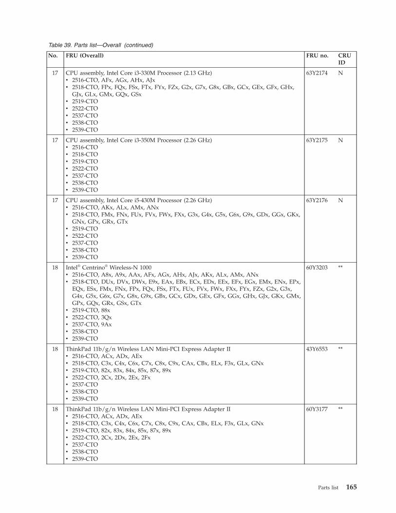
Table 39. Parts list—Overall (continued)
No. FRU (Overall) FRU no. CRUID
17 CPU assembly, Intel Core i3-330M Processor (2.13 GHz)v 2516-CTO, AFx, AGx, AHx, AJxv 2518-CTO, FPx, FQx, FSx, FTx, FYx, FZx, G2x, G7x, G8x, GBx, GCx, GEx, GFx, GHx,
GJx, GLx, GMx, GQx, GSxv 2519-CTOv 2522-CTOv 2537-CTOv 2538-CTOv 2539-CTO
63Y2174 N
17 CPU assembly, Intel Core i3-350M Processor (2.26 GHz)v 2516-CTOv 2518-CTOv 2519-CTOv 2522-CTOv 2537-CTOv 2538-CTOv 2539-CTO
63Y2175 N
17 CPU assembly, Intel Core i5-430M Processor (2.26 GHz)v 2516-CTO, AKx, ALx, AMx, ANxv 2518-CTO, FMx, FNx, FUx, FVx, FWx, FXx, G3x, G4x, G5x, G6x, G9x, GDx, GGx, GKx,
GNx, GPx, GRx, GTxv 2519-CTOv 2522-CTOv 2537-CTOv 2538-CTOv 2539-CTO
63Y2176 N
18 Intel® Centrino® Wireless-N 1000v 2516-CTO, A8x, A9x, AAx, AFx, AGx, AHx, AJx, AKx, ALx, AMx, ANxv 2518-CTO, DUx, DVx, DWx, E9x, EAx, EBx, ECx, EDx, EEx, EFx, EGx, EMx, ENx, EPx,
EQx, ESx, FMx, FNx, FPx, FQx, FSx, FTx, FUx, FVx, FWx, FXx, FYx, FZx, G2x, G3x,G4x, G5x, G6x, G7x, G8x, G9x, GBx, GCx, GDx, GEx, GFx, GGx, GHx, GJx, GKx, GMx,GPx, GQx, GRx, GSx, GTx
v 2519-CTO, 88xv 2522-CTO, 3Qxv 2537-CTO, 9Axv 2538-CTOv 2539-CTO
60Y3203 **
18 ThinkPad 11b/g/n Wireless LAN Mini-PCI Express Adapter IIv 2516-CTO, ACx, ADx, AExv 2518-CTO, C3x, C4x, C6x, C7x, C8x, C9x, CAx, CBx, ELx, F3x, GLx, GNxv 2519-CTO, 82x, 83x, 84x, 85x, 87x, 89xv 2522-CTO, 2Cx, 2Dx, 2Ex, 2Fxv 2537-CTOv 2538-CTOv 2539-CTO
43Y6553 **
18 ThinkPad 11b/g/n Wireless LAN Mini-PCI Express Adapter IIv 2516-CTO, ACx, ADx, AExv 2518-CTO, C3x, C4x, C6x, C7x, C8x, C9x, CAx, CBx, ELx, F3x, GLx, GNxv 2519-CTO, 82x, 83x, 84x, 85x, 87x, 89xv 2522-CTO, 2Cx, 2Dx, 2Ex, 2Fxv 2537-CTOv 2538-CTOv 2539-CTO
60Y3177 **
Parts list 165
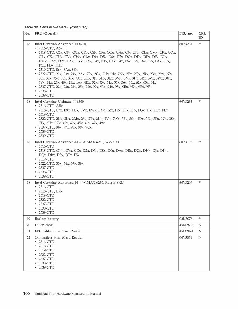
Table 39. Parts list—Overall (continued)
No. FRU (Overall) FRU no. CRUID
18 Intel Centrino Advanced-N 6200v 2516-CTO, A6xv 2518-CTO, C2x, C5x, CCx, CDx, CEx, CFx, CGx, CHx, CJx, CKx, CLx, CMx, CPx, CQx,
CRx, CSx, CUx, CVx, CWx, CXx, D4x, D5x, D6x, D7x, DCx, DDx, DEx, DFx, DLx,DMx, DNx, DPx, DXx, DYx, DZx, E4x, ETx, EXx, F4x, F6x, F7x, F8x, F9x, FAx, FBx,FCx, FDx, FHx
v 2519-CTO, 86x, 8Ax, 8Bxv 2522-CTO, 22x, 23x, 24x, 2Ax, 2Bx, 2Gx, 2Hx, 2Jx, 2Nx, 2Px, 2Qx, 2Rx, 2Xx, 2Yx, 2Zx,
30x, 32x, 35x, 36x, 39x, 3Ax, 3Hx, 3Jx, 3Kx, 3Lx, 3Mx, 3Nx, 3Px, 3Rx, 3Vx, 3Wx, 3Xx,3Yx, 44x, 25x, 48x, 26x, 4Ax, 4Bx, 52x, 53x, 54x, 55x, 56x, 60x, 62x, 63x, 64x
v 2537-CTO, 22x, 23x, 24x, 25x, 26x, 92x, 93x, 94x, 95x, 9Bx, 9Dx, 9Ex, 9Fxv 2538-CTOv 2539-CTO
60Y3231 **
18 Intel Centrino Ultimate-N 6300v 2516-CTO, ABxv 2518-CTO, E7x, E8x, EUx, EVx, EWx, EYx, EZx, F2x, FEx, FFx, FGx, FJx, FKx, FLxv 2519-CTOv 2522-CTO, 2Kx, 2Lx, 2Mx, 2Sx, 2Tx, 2Ux, 2Vx, 2Wx, 3Bx, 3Cx, 3Dx, 3Ex, 3Fx, 3Gx, 3Sx,
3Tx, 3Ux, 3Zx, 42x, 43x, 45x, 46x, 47x, 49xv 2537-CTO, 96x, 97x, 98x, 99x, 9Cxv 2538-CTOv 2539-CTO
60Y3233 **
18 Intel Centrino Advanced-N + WiMAX 6250, WW SKUv 2516-CTOv 2518-CTO, CNx, CYx, CZx, D2x, D3x, D8x, D9x, DAx, DBx, DGx, DHx, DJx, DKx,
DQx, DRx, DSx, DTx, F5xv 2519-CTOv 2522-CTO, 33x, 34x, 37x, 38xv 2537-CTOv 2538-CTOv 2539-CTO
60Y3195 **
18 Intel Centrino Advanced-N + WiMAX 6250, Russia SKUv 2516-CTOv 2518-CTO, ERxv 2519-CTOv 2522-CTOv 2537-CTOv 2538-CTOv 2539-CTO
60Y3209 **
19 Backup battery 02K7078 **
20 DC-in cable 45M2893 N
21 FPC cable, SmartCard Reader 45M2894 N
22 Contactless SmartCard Readerv 2516-CTOv 2518-CTOv 2519-CTOv 2522-CTOv 2537-CTOv 2538-CTOv 2539-CTO
60Y5031 N
166 ThinkPad T410 Hardware Maintenance Manual
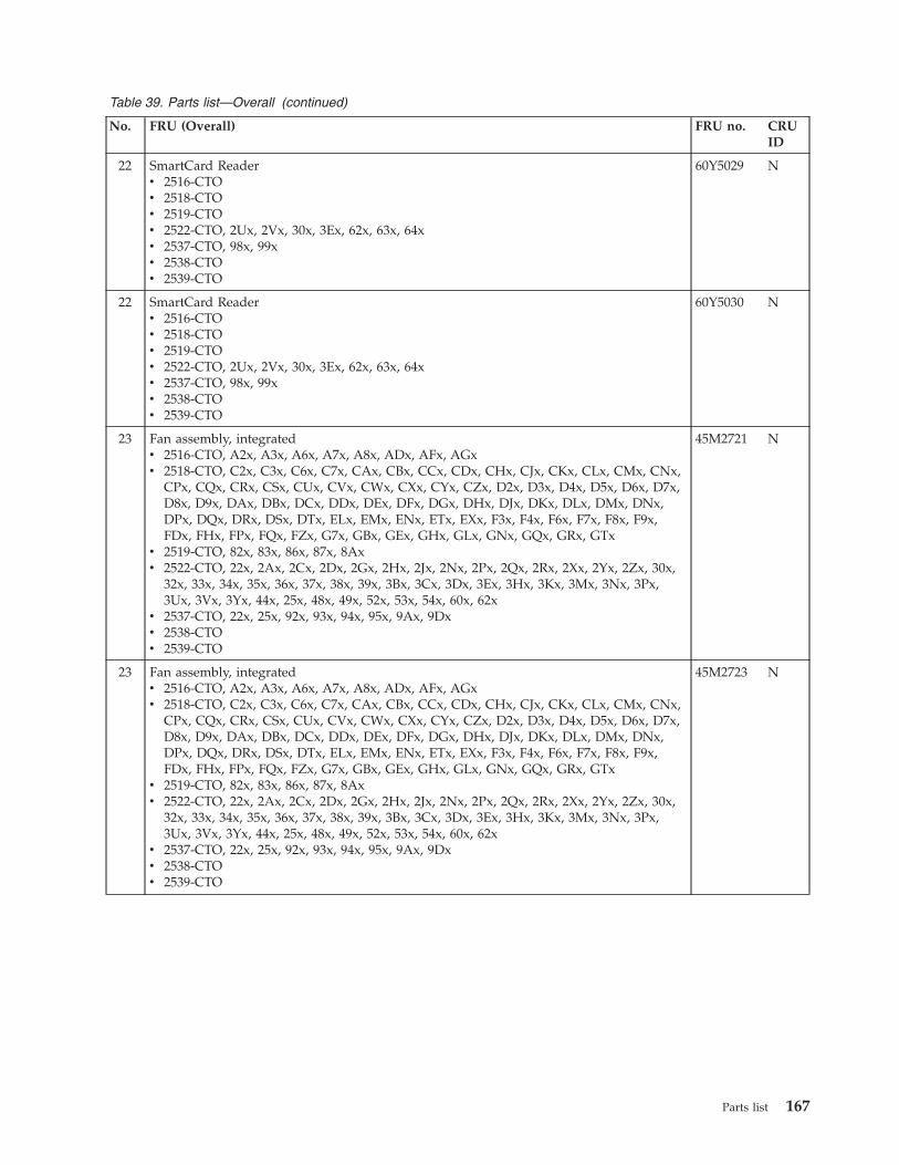
Table 39. Parts list—Overall (continued)
No. FRU (Overall) FRU no. CRUID
22 SmartCard Readerv 2516-CTOv 2518-CTOv 2519-CTOv 2522-CTO, 2Ux, 2Vx, 30x, 3Ex, 62x, 63x, 64xv 2537-CTO, 98x, 99xv 2538-CTOv 2539-CTO
60Y5029 N
22 SmartCard Readerv 2516-CTOv 2518-CTOv 2519-CTOv 2522-CTO, 2Ux, 2Vx, 30x, 3Ex, 62x, 63x, 64xv 2537-CTO, 98x, 99xv 2538-CTOv 2539-CTO
60Y5030 N
23 Fan assembly, integratedv 2516-CTO, A2x, A3x, A6x, A7x, A8x, ADx, AFx, AGxv 2518-CTO, C2x, C3x, C6x, C7x, CAx, CBx, CCx, CDx, CHx, CJx, CKx, CLx, CMx, CNx,
CPx, CQx, CRx, CSx, CUx, CVx, CWx, CXx, CYx, CZx, D2x, D3x, D4x, D5x, D6x, D7x,D8x, D9x, DAx, DBx, DCx, DDx, DEx, DFx, DGx, DHx, DJx, DKx, DLx, DMx, DNx,DPx, DQx, DRx, DSx, DTx, ELx, EMx, ENx, ETx, EXx, F3x, F4x, F6x, F7x, F8x, F9x,FDx, FHx, FPx, FQx, FZx, G7x, GBx, GEx, GHx, GLx, GNx, GQx, GRx, GTx
v 2519-CTO, 82x, 83x, 86x, 87x, 8Axv 2522-CTO, 22x, 2Ax, 2Cx, 2Dx, 2Gx, 2Hx, 2Jx, 2Nx, 2Px, 2Qx, 2Rx, 2Xx, 2Yx, 2Zx, 30x,
32x, 33x, 34x, 35x, 36x, 37x, 38x, 39x, 3Bx, 3Cx, 3Dx, 3Ex, 3Hx, 3Kx, 3Mx, 3Nx, 3Px,3Ux, 3Vx, 3Yx, 44x, 25x, 48x, 49x, 52x, 53x, 54x, 60x, 62x
v 2537-CTO, 22x, 25x, 92x, 93x, 94x, 95x, 9Ax, 9Dxv 2538-CTOv 2539-CTO
45M2721 N
23 Fan assembly, integratedv 2516-CTO, A2x, A3x, A6x, A7x, A8x, ADx, AFx, AGxv 2518-CTO, C2x, C3x, C6x, C7x, CAx, CBx, CCx, CDx, CHx, CJx, CKx, CLx, CMx, CNx,
CPx, CQx, CRx, CSx, CUx, CVx, CWx, CXx, CYx, CZx, D2x, D3x, D4x, D5x, D6x, D7x,D8x, D9x, DAx, DBx, DCx, DDx, DEx, DFx, DGx, DHx, DJx, DKx, DLx, DMx, DNx,DPx, DQx, DRx, DSx, DTx, ELx, EMx, ENx, ETx, EXx, F3x, F4x, F6x, F7x, F8x, F9x,FDx, FHx, FPx, FQx, FZx, G7x, GBx, GEx, GHx, GLx, GNx, GQx, GRx, GTx
v 2519-CTO, 82x, 83x, 86x, 87x, 8Axv 2522-CTO, 22x, 2Ax, 2Cx, 2Dx, 2Gx, 2Hx, 2Jx, 2Nx, 2Px, 2Qx, 2Rx, 2Xx, 2Yx, 2Zx, 30x,
32x, 33x, 34x, 35x, 36x, 37x, 38x, 39x, 3Bx, 3Cx, 3Dx, 3Ex, 3Hx, 3Kx, 3Mx, 3Nx, 3Px,3Ux, 3Vx, 3Yx, 44x, 25x, 48x, 49x, 52x, 53x, 54x, 60x, 62x
v 2537-CTO, 22x, 25x, 92x, 93x, 94x, 95x, 9Ax, 9Dxv 2538-CTOv 2539-CTO
45M2723 N
Parts list 167
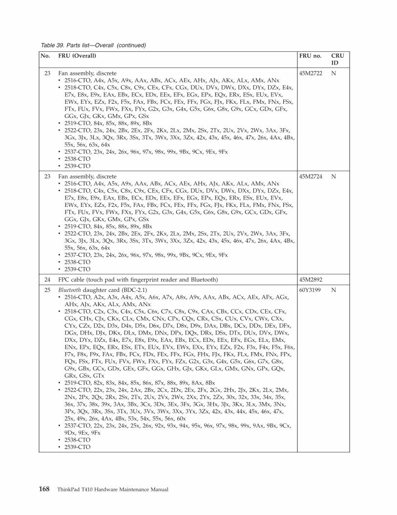
Table 39. Parts list—Overall (continued)
No. FRU (Overall) FRU no. CRUID
23 Fan assembly, discretev 2516-CTO, A4x, A5x, A9x, AAx, ABx, ACx, AEx, AHx, AJx, AKx, ALx, AMx, ANxv 2518-CTO, C4x, C5x, C8x, C9x, CEx, CFx, CGx, DUx, DVx, DWx, DXx, DYx, DZx, E4x,
E7x, E8x, E9x, EAx, EBx, ECx, EDx, EEx, EFx, EGx, EPx, EQx, ERx, ESx, EUx, EVx,EWx, EYx, EZx, F2x, F5x, FAx, FBx, FCx, FEx, FFx, FGx, FJx, FKx, FLx, FMx, FNx, FSx,FTx, FUx, FVx, FWx, FXx, FYx, G2x, G3x, G4x, G5x, G6x, G8x, G9x, GCx, GDx, GFx,GGx, GJx, GKx, GMx, GPx, GSx
v 2519-CTO, 84x, 85x, 88x, 89x, 8Bxv 2522-CTO, 23x, 24x, 2Bx, 2Ex, 2Fx, 2Kx, 2Lx, 2Mx, 2Sx, 2Tx, 2Ux, 2Vx, 2Wx, 3Ax, 3Fx,
3Gx, 3Jx, 3Lx, 3Qx, 3Rx, 3Sx, 3Tx, 3Wx, 3Xx, 3Zx, 42x, 43x, 45x, 46x, 47x, 26x, 4Ax, 4Bx,55x, 56x, 63x, 64x
v 2537-CTO, 23x, 24x, 26x, 96x, 97x, 98x, 99x, 9Bx, 9Cx, 9Ex, 9Fxv 2538-CTOv 2539-CTO
45M2722 N
23 Fan assembly, discretev 2516-CTO, A4x, A5x, A9x, AAx, ABx, ACx, AEx, AHx, AJx, AKx, ALx, AMx, ANxv 2518-CTO, C4x, C5x, C8x, C9x, CEx, CFx, CGx, DUx, DVx, DWx, DXx, DYx, DZx, E4x,
E7x, E8x, E9x, EAx, EBx, ECx, EDx, EEx, EFx, EGx, EPx, EQx, ERx, ESx, EUx, EVx,EWx, EYx, EZx, F2x, F5x, FAx, FBx, FCx, FEx, FFx, FGx, FJx, FKx, FLx, FMx, FNx, FSx,FTx, FUx, FVx, FWx, FXx, FYx, G2x, G3x, G4x, G5x, G6x, G8x, G9x, GCx, GDx, GFx,GGx, GJx, GKx, GMx, GPx, GSx
v 2519-CTO, 84x, 85x, 88x, 89x, 8Bxv 2522-CTO, 23x, 24x, 2Bx, 2Ex, 2Fx, 2Kx, 2Lx, 2Mx, 2Sx, 2Tx, 2Ux, 2Vx, 2Wx, 3Ax, 3Fx,
3Gx, 3Jx, 3Lx, 3Qx, 3Rx, 3Sx, 3Tx, 3Wx, 3Xx, 3Zx, 42x, 43x, 45x, 46x, 47x, 26x, 4Ax, 4Bx,55x, 56x, 63x, 64x
v 2537-CTO, 23x, 24x, 26x, 96x, 97x, 98x, 99x, 9Bx, 9Cx, 9Ex, 9Fxv 2538-CTOv 2539-CTO
45M2724 N
24 FPC cable (touch pad with fingerprint reader and Bluetooth) 45M2892
25 Bluetooth daughter card (BDC-2.1)v 2516-CTO, A2x, A3x, A4x, A5x, A6x, A7x, A8x, A9x, AAx, ABx, ACx, AEx, AFx, AGx,
AHx, AJx, AKx, ALx, AMx, ANxv 2518-CTO, C2x, C3x, C4x, C5x, C6x, C7x, C8x, C9x, CAx, CBx, CCx, CDx, CEx, CFx,
CGx, CHx, CJx, CKx, CLx, CMx, CNx, CPx, CQx, CRx, CSx, CUx, CVx, CWx, CXx,CYx, CZx, D2x, D3x, D4x, D5x, D6x, D7x, D8x, D9x, DAx, DBx, DCx, DDx, DEx, DFx,DGx, DHx, DJx, DKx, DLx, DMx, DNx, DPx, DQx, DRx, DSx, DTx, DUx, DVx, DWx,DXx, DYx, DZx, E4x, E7x, E8x, E9x, EAx, EBx, ECx, EDx, EEx, EFx, EGx, ELx, EMx,ENx, EPx, EQx, ERx, ESx, ETx, EUx, EVx, EWx, EXx, EYx, EZx, F2x, F3x, F4x, F5x, F6x,F7x, F8x, F9x, FAx, FBx, FCx, FDx, FEx, FFx, FGx, FHx, FJx, FKx, FLx, FMx, FNx, FPx,FQx, FSx, FTx, FUx, FVx, FWx, FXx, FYx, FZx, G2x, G3x, G4x, G5x, G6x, G7x, G8x,G9x, GBx, GCx, GDx, GEx, GFx, GGx, GHx, GJx, GKx, GLx, GMx, GNx, GPx, GQx,GRx, GSx, GTx
v 2519-CTO, 82x, 83x, 84x, 85x, 86x, 87x, 88x, 89x, 8Ax, 8Bxv 2522-CTO, 22x, 23x, 24x, 2Ax, 2Bx, 2Cx, 2Dx, 2Ex, 2Fx, 2Gx, 2Hx, 2Jx, 2Kx, 2Lx, 2Mx,
2Nx, 2Px, 2Qx, 2Rx, 2Sx, 2Tx, 2Ux, 2Vx, 2Wx, 2Xx, 2Yx, 2Zx, 30x, 32x, 33x, 34x, 35x,36x, 37x, 38x, 39x, 3Ax, 3Bx, 3Cx, 3Dx, 3Ex, 3Fx, 3Gx, 3Hx, 3Jx, 3Kx, 3Lx, 3Mx, 3Nx,3Px, 3Qx, 3Rx, 3Sx, 3Tx, 3Ux, 3Vx, 3Wx, 3Xx, 3Yx, 3Zx, 42x, 43x, 44x, 45x, 46x, 47x,25x, 49x, 26x, 4Ax, 4Bx, 53x, 54x, 55x, 56x, 60x
v 2537-CTO, 22x, 23x, 24x, 25x, 26x, 92x, 93x, 94x, 95x, 96x, 97x, 98x, 99x, 9Ax, 9Bx, 9Cx,9Dx, 9Ex, 9Fx
v 2538-CTOv 2539-CTO
60Y3199 N
168 ThinkPad T410 Hardware Maintenance Manual
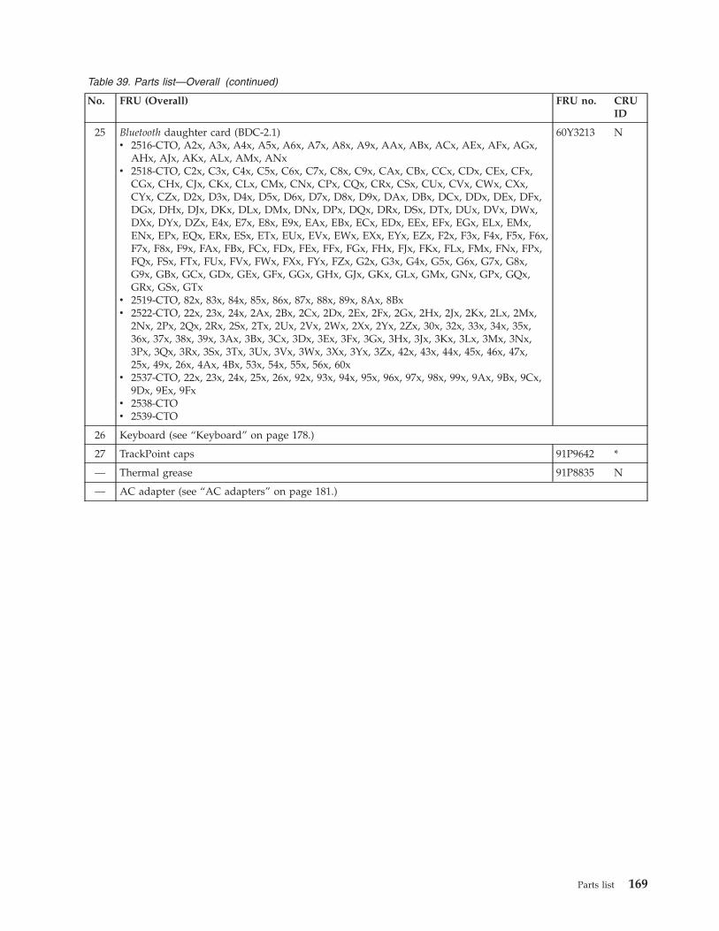
Table 39. Parts list—Overall (continued)
No. FRU (Overall) FRU no. CRUID
25 Bluetooth daughter card (BDC-2.1)v 2516-CTO, A2x, A3x, A4x, A5x, A6x, A7x, A8x, A9x, AAx, ABx, ACx, AEx, AFx, AGx,
AHx, AJx, AKx, ALx, AMx, ANxv 2518-CTO, C2x, C3x, C4x, C5x, C6x, C7x, C8x, C9x, CAx, CBx, CCx, CDx, CEx, CFx,
CGx, CHx, CJx, CKx, CLx, CMx, CNx, CPx, CQx, CRx, CSx, CUx, CVx, CWx, CXx,CYx, CZx, D2x, D3x, D4x, D5x, D6x, D7x, D8x, D9x, DAx, DBx, DCx, DDx, DEx, DFx,DGx, DHx, DJx, DKx, DLx, DMx, DNx, DPx, DQx, DRx, DSx, DTx, DUx, DVx, DWx,DXx, DYx, DZx, E4x, E7x, E8x, E9x, EAx, EBx, ECx, EDx, EEx, EFx, EGx, ELx, EMx,ENx, EPx, EQx, ERx, ESx, ETx, EUx, EVx, EWx, EXx, EYx, EZx, F2x, F3x, F4x, F5x, F6x,F7x, F8x, F9x, FAx, FBx, FCx, FDx, FEx, FFx, FGx, FHx, FJx, FKx, FLx, FMx, FNx, FPx,FQx, FSx, FTx, FUx, FVx, FWx, FXx, FYx, FZx, G2x, G3x, G4x, G5x, G6x, G7x, G8x,G9x, GBx, GCx, GDx, GEx, GFx, GGx, GHx, GJx, GKx, GLx, GMx, GNx, GPx, GQx,GRx, GSx, GTx
v 2519-CTO, 82x, 83x, 84x, 85x, 86x, 87x, 88x, 89x, 8Ax, 8Bxv 2522-CTO, 22x, 23x, 24x, 2Ax, 2Bx, 2Cx, 2Dx, 2Ex, 2Fx, 2Gx, 2Hx, 2Jx, 2Kx, 2Lx, 2Mx,
2Nx, 2Px, 2Qx, 2Rx, 2Sx, 2Tx, 2Ux, 2Vx, 2Wx, 2Xx, 2Yx, 2Zx, 30x, 32x, 33x, 34x, 35x,36x, 37x, 38x, 39x, 3Ax, 3Bx, 3Cx, 3Dx, 3Ex, 3Fx, 3Gx, 3Hx, 3Jx, 3Kx, 3Lx, 3Mx, 3Nx,3Px, 3Qx, 3Rx, 3Sx, 3Tx, 3Ux, 3Vx, 3Wx, 3Xx, 3Yx, 3Zx, 42x, 43x, 44x, 45x, 46x, 47x,25x, 49x, 26x, 4Ax, 4Bx, 53x, 54x, 55x, 56x, 60x
v 2537-CTO, 22x, 23x, 24x, 25x, 26x, 92x, 93x, 94x, 95x, 96x, 97x, 98x, 99x, 9Ax, 9Bx, 9Cx,9Dx, 9Ex, 9Fx
v 2538-CTOv 2539-CTO
60Y3213 N
26 Keyboard (see “Keyboard” on page 178.)
27 TrackPoint caps 91P9642 *
— Thermal grease 91P8835 N
— AC adapter (see “AC adapters” on page 181.)
Parts list 169
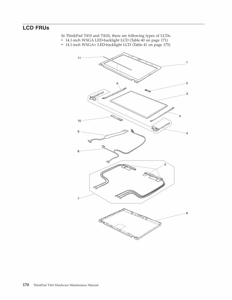
LCD FRUsIn ThinkPad T410 and T410i, there are following types of LCDs.v 14.1-inch WXGA LED-backlight LCD (Table 40 on page 171)v 14.1-inch WXGA+ LED-backlight LCD (Table 41 on page 175)
1
2
3
a
b
4
5
6
8
7
9
10
11
170 ThinkPad T410 Hardware Maintenance Manual
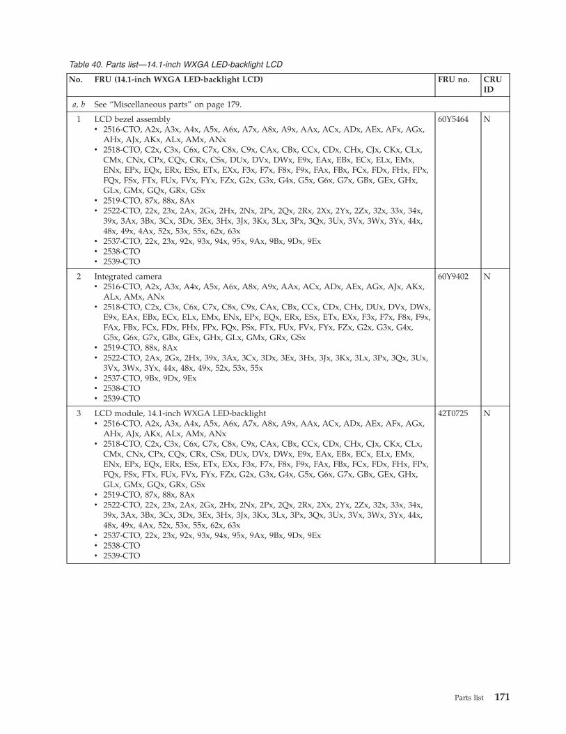
Table 40. Parts list—14.1-inch WXGA LED-backlight LCD
No. FRU (14.1-inch WXGA LED-backlight LCD) FRU no. CRUID
a, b See “Miscellaneous parts” on page 179.
1 LCD bezel assemblyv 2516-CTO, A2x, A3x, A4x, A5x, A6x, A7x, A8x, A9x, AAx, ACx, ADx, AEx, AFx, AGx,
AHx, AJx, AKx, ALx, AMx, ANxv 2518-CTO, C2x, C3x, C6x, C7x, C8x, C9x, CAx, CBx, CCx, CDx, CHx, CJx, CKx, CLx,
CMx, CNx, CPx, CQx, CRx, CSx, DUx, DVx, DWx, E9x, EAx, EBx, ECx, ELx, EMx,ENx, EPx, EQx, ERx, ESx, ETx, EXx, F3x, F7x, F8x, F9x, FAx, FBx, FCx, FDx, FHx, FPx,FQx, FSx, FTx, FUx, FVx, FYx, FZx, G2x, G3x, G4x, G5x, G6x, G7x, GBx, GEx, GHx,GLx, GMx, GQx, GRx, GSx
v 2519-CTO, 87x, 88x, 8Axv 2522-CTO, 22x, 23x, 2Ax, 2Gx, 2Hx, 2Nx, 2Px, 2Qx, 2Rx, 2Xx, 2Yx, 2Zx, 32x, 33x, 34x,
39x, 3Ax, 3Bx, 3Cx, 3Dx, 3Ex, 3Hx, 3Jx, 3Kx, 3Lx, 3Px, 3Qx, 3Ux, 3Vx, 3Wx, 3Yx, 44x,48x, 49x, 4Ax, 52x, 53x, 55x, 62x, 63x
v 2537-CTO, 22x, 23x, 92x, 93x, 94x, 95x, 9Ax, 9Bx, 9Dx, 9Exv 2538-CTOv 2539-CTO
60Y5464 N
2 Integrated camerav 2516-CTO, A2x, A3x, A4x, A5x, A6x, A8x, A9x, AAx, ACx, ADx, AEx, AGx, AJx, AKx,
ALx, AMx, ANxv 2518-CTO, C2x, C3x, C6x, C7x, C8x, C9x, CAx, CBx, CCx, CDx, CHx, DUx, DVx, DWx,
E9x, EAx, EBx, ECx, ELx, EMx, ENx, EPx, EQx, ERx, ESx, ETx, EXx, F3x, F7x, F8x, F9x,FAx, FBx, FCx, FDx, FHx, FPx, FQx, FSx, FTx, FUx, FVx, FYx, FZx, G2x, G3x, G4x,G5x, G6x, G7x, GBx, GEx, GHx, GLx, GMx, GRx, GSx
v 2519-CTO, 88x, 8Axv 2522-CTO, 2Ax, 2Gx, 2Hx, 39x, 3Ax, 3Cx, 3Dx, 3Ex, 3Hx, 3Jx, 3Kx, 3Lx, 3Px, 3Qx, 3Ux,
3Vx, 3Wx, 3Yx, 44x, 48x, 49x, 52x, 53x, 55xv 2537-CTO, 9Bx, 9Dx, 9Exv 2538-CTOv 2539-CTO
60Y9402 N
3 LCD module, 14.1-inch WXGA LED-backlightv 2516-CTO, A2x, A3x, A4x, A5x, A6x, A7x, A8x, A9x, AAx, ACx, ADx, AEx, AFx, AGx,
AHx, AJx, AKx, ALx, AMx, ANxv 2518-CTO, C2x, C3x, C6x, C7x, C8x, C9x, CAx, CBx, CCx, CDx, CHx, CJx, CKx, CLx,
CMx, CNx, CPx, CQx, CRx, CSx, DUx, DVx, DWx, E9x, EAx, EBx, ECx, ELx, EMx,ENx, EPx, EQx, ERx, ESx, ETx, EXx, F3x, F7x, F8x, F9x, FAx, FBx, FCx, FDx, FHx, FPx,FQx, FSx, FTx, FUx, FVx, FYx, FZx, G2x, G3x, G4x, G5x, G6x, G7x, GBx, GEx, GHx,GLx, GMx, GQx, GRx, GSx
v 2519-CTO, 87x, 88x, 8Axv 2522-CTO, 22x, 23x, 2Ax, 2Gx, 2Hx, 2Nx, 2Px, 2Qx, 2Rx, 2Xx, 2Yx, 2Zx, 32x, 33x, 34x,
39x, 3Ax, 3Bx, 3Cx, 3Dx, 3Ex, 3Hx, 3Jx, 3Kx, 3Lx, 3Px, 3Qx, 3Ux, 3Vx, 3Wx, 3Yx, 44x,48x, 49x, 4Ax, 52x, 53x, 55x, 62x, 63x
v 2537-CTO, 22x, 23x, 92x, 93x, 94x, 95x, 9Ax, 9Bx, 9Dx, 9Exv 2538-CTOv 2539-CTO
42T0725 N
Parts list 171
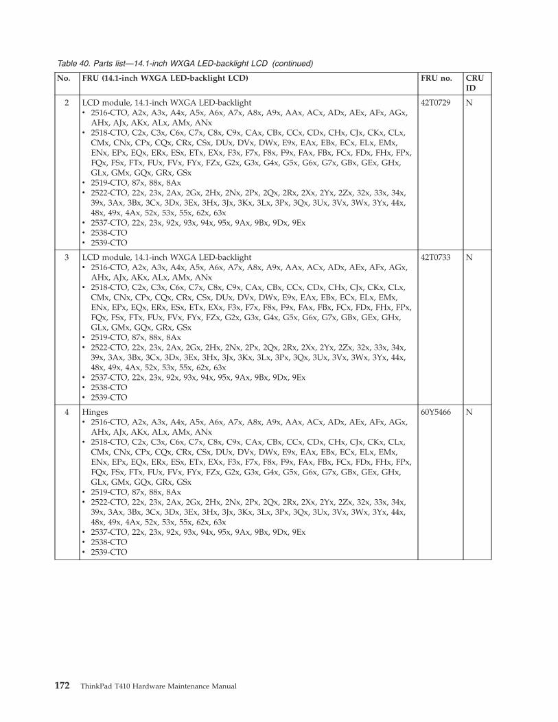
Table 40. Parts list—14.1-inch WXGA LED-backlight LCD (continued)
No. FRU (14.1-inch WXGA LED-backlight LCD) FRU no. CRUID
2 LCD module, 14.1-inch WXGA LED-backlightv 2516-CTO, A2x, A3x, A4x, A5x, A6x, A7x, A8x, A9x, AAx, ACx, ADx, AEx, AFx, AGx,
AHx, AJx, AKx, ALx, AMx, ANxv 2518-CTO, C2x, C3x, C6x, C7x, C8x, C9x, CAx, CBx, CCx, CDx, CHx, CJx, CKx, CLx,
CMx, CNx, CPx, CQx, CRx, CSx, DUx, DVx, DWx, E9x, EAx, EBx, ECx, ELx, EMx,ENx, EPx, EQx, ERx, ESx, ETx, EXx, F3x, F7x, F8x, F9x, FAx, FBx, FCx, FDx, FHx, FPx,FQx, FSx, FTx, FUx, FVx, FYx, FZx, G2x, G3x, G4x, G5x, G6x, G7x, GBx, GEx, GHx,GLx, GMx, GQx, GRx, GSx
v 2519-CTO, 87x, 88x, 8Axv 2522-CTO, 22x, 23x, 2Ax, 2Gx, 2Hx, 2Nx, 2Px, 2Qx, 2Rx, 2Xx, 2Yx, 2Zx, 32x, 33x, 34x,
39x, 3Ax, 3Bx, 3Cx, 3Dx, 3Ex, 3Hx, 3Jx, 3Kx, 3Lx, 3Px, 3Qx, 3Ux, 3Vx, 3Wx, 3Yx, 44x,48x, 49x, 4Ax, 52x, 53x, 55x, 62x, 63x
v 2537-CTO, 22x, 23x, 92x, 93x, 94x, 95x, 9Ax, 9Bx, 9Dx, 9Exv 2538-CTOv 2539-CTO
42T0729 N
3 LCD module, 14.1-inch WXGA LED-backlightv 2516-CTO, A2x, A3x, A4x, A5x, A6x, A7x, A8x, A9x, AAx, ACx, ADx, AEx, AFx, AGx,
AHx, AJx, AKx, ALx, AMx, ANxv 2518-CTO, C2x, C3x, C6x, C7x, C8x, C9x, CAx, CBx, CCx, CDx, CHx, CJx, CKx, CLx,
CMx, CNx, CPx, CQx, CRx, CSx, DUx, DVx, DWx, E9x, EAx, EBx, ECx, ELx, EMx,ENx, EPx, EQx, ERx, ESx, ETx, EXx, F3x, F7x, F8x, F9x, FAx, FBx, FCx, FDx, FHx, FPx,FQx, FSx, FTx, FUx, FVx, FYx, FZx, G2x, G3x, G4x, G5x, G6x, G7x, GBx, GEx, GHx,GLx, GMx, GQx, GRx, GSx
v 2519-CTO, 87x, 88x, 8Axv 2522-CTO, 22x, 23x, 2Ax, 2Gx, 2Hx, 2Nx, 2Px, 2Qx, 2Rx, 2Xx, 2Yx, 2Zx, 32x, 33x, 34x,
39x, 3Ax, 3Bx, 3Cx, 3Dx, 3Ex, 3Hx, 3Jx, 3Kx, 3Lx, 3Px, 3Qx, 3Ux, 3Vx, 3Wx, 3Yx, 44x,48x, 49x, 4Ax, 52x, 53x, 55x, 62x, 63x
v 2537-CTO, 22x, 23x, 92x, 93x, 94x, 95x, 9Ax, 9Bx, 9Dx, 9Exv 2538-CTOv 2539-CTO
42T0733 N
4 Hingesv 2516-CTO, A2x, A3x, A4x, A5x, A6x, A7x, A8x, A9x, AAx, ACx, ADx, AEx, AFx, AGx,
AHx, AJx, AKx, ALx, AMx, ANxv 2518-CTO, C2x, C3x, C6x, C7x, C8x, C9x, CAx, CBx, CCx, CDx, CHx, CJx, CKx, CLx,
CMx, CNx, CPx, CQx, CRx, CSx, DUx, DVx, DWx, E9x, EAx, EBx, ECx, ELx, EMx,ENx, EPx, EQx, ERx, ESx, ETx, EXx, F3x, F7x, F8x, F9x, FAx, FBx, FCx, FDx, FHx, FPx,FQx, FSx, FTx, FUx, FVx, FYx, FZx, G2x, G3x, G4x, G5x, G6x, G7x, GBx, GEx, GHx,GLx, GMx, GQx, GRx, GSx
v 2519-CTO, 87x, 88x, 8Axv 2522-CTO, 22x, 23x, 2Ax, 2Gx, 2Hx, 2Nx, 2Px, 2Qx, 2Rx, 2Xx, 2Yx, 2Zx, 32x, 33x, 34x,
39x, 3Ax, 3Bx, 3Cx, 3Dx, 3Ex, 3Hx, 3Jx, 3Kx, 3Lx, 3Px, 3Qx, 3Ux, 3Vx, 3Wx, 3Yx, 44x,48x, 49x, 4Ax, 52x, 53x, 55x, 62x, 63x
v 2537-CTO, 22x, 23x, 92x, 93x, 94x, 95x, 9Ax, 9Bx, 9Dx, 9Exv 2538-CTOv 2539-CTO
60Y5466 N
172 ThinkPad T410 Hardware Maintenance Manual
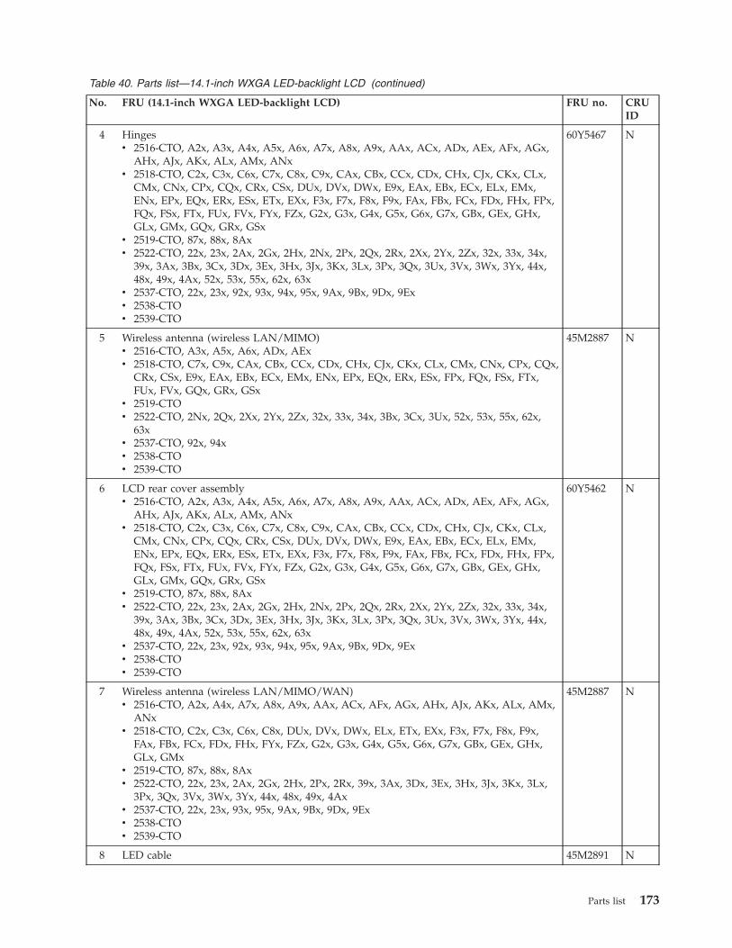
Table 40. Parts list—14.1-inch WXGA LED-backlight LCD (continued)
No. FRU (14.1-inch WXGA LED-backlight LCD) FRU no. CRUID
4 Hingesv 2516-CTO, A2x, A3x, A4x, A5x, A6x, A7x, A8x, A9x, AAx, ACx, ADx, AEx, AFx, AGx,
AHx, AJx, AKx, ALx, AMx, ANxv 2518-CTO, C2x, C3x, C6x, C7x, C8x, C9x, CAx, CBx, CCx, CDx, CHx, CJx, CKx, CLx,
CMx, CNx, CPx, CQx, CRx, CSx, DUx, DVx, DWx, E9x, EAx, EBx, ECx, ELx, EMx,ENx, EPx, EQx, ERx, ESx, ETx, EXx, F3x, F7x, F8x, F9x, FAx, FBx, FCx, FDx, FHx, FPx,FQx, FSx, FTx, FUx, FVx, FYx, FZx, G2x, G3x, G4x, G5x, G6x, G7x, GBx, GEx, GHx,GLx, GMx, GQx, GRx, GSx
v 2519-CTO, 87x, 88x, 8Axv 2522-CTO, 22x, 23x, 2Ax, 2Gx, 2Hx, 2Nx, 2Px, 2Qx, 2Rx, 2Xx, 2Yx, 2Zx, 32x, 33x, 34x,
39x, 3Ax, 3Bx, 3Cx, 3Dx, 3Ex, 3Hx, 3Jx, 3Kx, 3Lx, 3Px, 3Qx, 3Ux, 3Vx, 3Wx, 3Yx, 44x,48x, 49x, 4Ax, 52x, 53x, 55x, 62x, 63x
v 2537-CTO, 22x, 23x, 92x, 93x, 94x, 95x, 9Ax, 9Bx, 9Dx, 9Exv 2538-CTOv 2539-CTO
60Y5467 N
5 Wireless antenna (wireless LAN/MIMO)v 2516-CTO, A3x, A5x, A6x, ADx, AExv 2518-CTO, C7x, C9x, CAx, CBx, CCx, CDx, CHx, CJx, CKx, CLx, CMx, CNx, CPx, CQx,
CRx, CSx, E9x, EAx, EBx, ECx, EMx, ENx, EPx, EQx, ERx, ESx, FPx, FQx, FSx, FTx,FUx, FVx, GQx, GRx, GSx
v 2519-CTOv 2522-CTO, 2Nx, 2Qx, 2Xx, 2Yx, 2Zx, 32x, 33x, 34x, 3Bx, 3Cx, 3Ux, 52x, 53x, 55x, 62x,
63xv 2537-CTO, 92x, 94xv 2538-CTOv 2539-CTO
45M2887 N
6 LCD rear cover assemblyv 2516-CTO, A2x, A3x, A4x, A5x, A6x, A7x, A8x, A9x, AAx, ACx, ADx, AEx, AFx, AGx,
AHx, AJx, AKx, ALx, AMx, ANxv 2518-CTO, C2x, C3x, C6x, C7x, C8x, C9x, CAx, CBx, CCx, CDx, CHx, CJx, CKx, CLx,
CMx, CNx, CPx, CQx, CRx, CSx, DUx, DVx, DWx, E9x, EAx, EBx, ECx, ELx, EMx,ENx, EPx, EQx, ERx, ESx, ETx, EXx, F3x, F7x, F8x, F9x, FAx, FBx, FCx, FDx, FHx, FPx,FQx, FSx, FTx, FUx, FVx, FYx, FZx, G2x, G3x, G4x, G5x, G6x, G7x, GBx, GEx, GHx,GLx, GMx, GQx, GRx, GSx
v 2519-CTO, 87x, 88x, 8Axv 2522-CTO, 22x, 23x, 2Ax, 2Gx, 2Hx, 2Nx, 2Px, 2Qx, 2Rx, 2Xx, 2Yx, 2Zx, 32x, 33x, 34x,
39x, 3Ax, 3Bx, 3Cx, 3Dx, 3Ex, 3Hx, 3Jx, 3Kx, 3Lx, 3Px, 3Qx, 3Ux, 3Vx, 3Wx, 3Yx, 44x,48x, 49x, 4Ax, 52x, 53x, 55x, 62x, 63x
v 2537-CTO, 22x, 23x, 92x, 93x, 94x, 95x, 9Ax, 9Bx, 9Dx, 9Exv 2538-CTOv 2539-CTO
60Y5462 N
7 Wireless antenna (wireless LAN/MIMO/WAN)v 2516-CTO, A2x, A4x, A7x, A8x, A9x, AAx, ACx, AFx, AGx, AHx, AJx, AKx, ALx, AMx,
ANxv 2518-CTO, C2x, C3x, C6x, C8x, DUx, DVx, DWx, ELx, ETx, EXx, F3x, F7x, F8x, F9x,
FAx, FBx, FCx, FDx, FHx, FYx, FZx, G2x, G3x, G4x, G5x, G6x, G7x, GBx, GEx, GHx,GLx, GMx
v 2519-CTO, 87x, 88x, 8Axv 2522-CTO, 22x, 23x, 2Ax, 2Gx, 2Hx, 2Px, 2Rx, 39x, 3Ax, 3Dx, 3Ex, 3Hx, 3Jx, 3Kx, 3Lx,
3Px, 3Qx, 3Vx, 3Wx, 3Yx, 44x, 48x, 49x, 4Axv 2537-CTO, 22x, 23x, 93x, 95x, 9Ax, 9Bx, 9Dx, 9Exv 2538-CTOv 2539-CTO
45M2887 N
8 LED cable 45M2891 N
Parts list 173
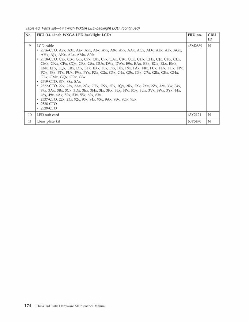
Table 40. Parts list—14.1-inch WXGA LED-backlight LCD (continued)
No. FRU (14.1-inch WXGA LED-backlight LCD) FRU no. CRUID
9 LCD cablev 2516-CTO, A2x, A3x, A4x, A5x, A6x, A7x, A8x, A9x, AAx, ACx, ADx, AEx, AFx, AGx,
AHx, AJx, AKx, ALx, AMx, ANxv 2518-CTO, C2x, C3x, C6x, C7x, C8x, C9x, CAx, CBx, CCx, CDx, CHx, CJx, CKx, CLx,
CMx, CNx, CPx, CQx, CRx, CSx, DUx, DVx, DWx, E9x, EAx, EBx, ECx, ELx, EMx,ENx, EPx, EQx, ERx, ESx, ETx, EXx, F3x, F7x, F8x, F9x, FAx, FBx, FCx, FDx, FHx, FPx,FQx, FSx, FTx, FUx, FVx, FYx, FZx, G2x, G3x, G4x, G5x, G6x, G7x, GBx, GEx, GHx,GLx, GMx, GQx, GRx, GSx
v 2519-CTO, 87x, 88x, 8Axv 2522-CTO, 22x, 23x, 2Ax, 2Gx, 2Hx, 2Nx, 2Px, 2Qx, 2Rx, 2Xx, 2Yx, 2Zx, 32x, 33x, 34x,
39x, 3Ax, 3Bx, 3Cx, 3Dx, 3Ex, 3Hx, 3Jx, 3Kx, 3Lx, 3Px, 3Qx, 3Ux, 3Vx, 3Wx, 3Yx, 44x,48x, 49x, 4Ax, 52x, 53x, 55x, 62x, 63x
v 2537-CTO, 22x, 23x, 92x, 93x, 94x, 95x, 9Ax, 9Bx, 9Dx, 9Exv 2538-CTOv 2539-CTO
45M2889 N
10 LED sub card 63Y2121 N
11 Clear plate kit 60Y5470 N
174 ThinkPad T410 Hardware Maintenance Manual
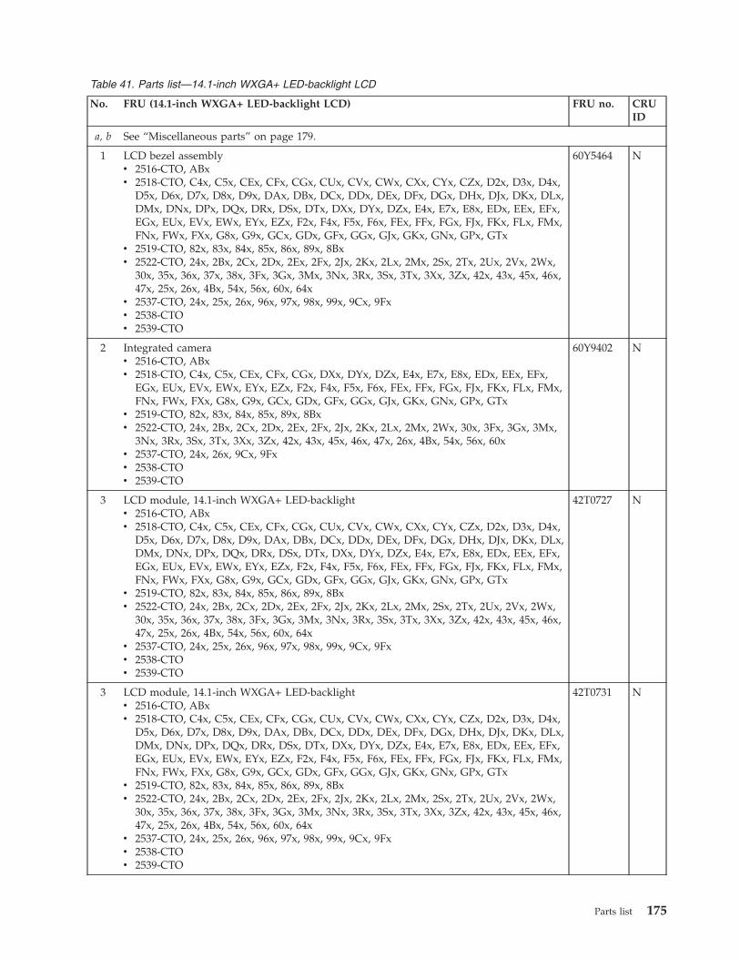
Table 41. Parts list—14.1-inch WXGA+ LED-backlight LCD
No. FRU (14.1-inch WXGA+ LED-backlight LCD) FRU no. CRUID
a, b See “Miscellaneous parts” on page 179.
1 LCD bezel assemblyv 2516-CTO, ABxv 2518-CTO, C4x, C5x, CEx, CFx, CGx, CUx, CVx, CWx, CXx, CYx, CZx, D2x, D3x, D4x,
D5x, D6x, D7x, D8x, D9x, DAx, DBx, DCx, DDx, DEx, DFx, DGx, DHx, DJx, DKx, DLx,DMx, DNx, DPx, DQx, DRx, DSx, DTx, DXx, DYx, DZx, E4x, E7x, E8x, EDx, EEx, EFx,EGx, EUx, EVx, EWx, EYx, EZx, F2x, F4x, F5x, F6x, FEx, FFx, FGx, FJx, FKx, FLx, FMx,FNx, FWx, FXx, G8x, G9x, GCx, GDx, GFx, GGx, GJx, GKx, GNx, GPx, GTx
v 2519-CTO, 82x, 83x, 84x, 85x, 86x, 89x, 8Bxv 2522-CTO, 24x, 2Bx, 2Cx, 2Dx, 2Ex, 2Fx, 2Jx, 2Kx, 2Lx, 2Mx, 2Sx, 2Tx, 2Ux, 2Vx, 2Wx,
30x, 35x, 36x, 37x, 38x, 3Fx, 3Gx, 3Mx, 3Nx, 3Rx, 3Sx, 3Tx, 3Xx, 3Zx, 42x, 43x, 45x, 46x,47x, 25x, 26x, 4Bx, 54x, 56x, 60x, 64x
v 2537-CTO, 24x, 25x, 26x, 96x, 97x, 98x, 99x, 9Cx, 9Fxv 2538-CTOv 2539-CTO
60Y5464 N
2 Integrated camerav 2516-CTO, ABxv 2518-CTO, C4x, C5x, CEx, CFx, CGx, DXx, DYx, DZx, E4x, E7x, E8x, EDx, EEx, EFx,
EGx, EUx, EVx, EWx, EYx, EZx, F2x, F4x, F5x, F6x, FEx, FFx, FGx, FJx, FKx, FLx, FMx,FNx, FWx, FXx, G8x, G9x, GCx, GDx, GFx, GGx, GJx, GKx, GNx, GPx, GTx
v 2519-CTO, 82x, 83x, 84x, 85x, 89x, 8Bxv 2522-CTO, 24x, 2Bx, 2Cx, 2Dx, 2Ex, 2Fx, 2Jx, 2Kx, 2Lx, 2Mx, 2Wx, 30x, 3Fx, 3Gx, 3Mx,
3Nx, 3Rx, 3Sx, 3Tx, 3Xx, 3Zx, 42x, 43x, 45x, 46x, 47x, 26x, 4Bx, 54x, 56x, 60xv 2537-CTO, 24x, 26x, 9Cx, 9Fxv 2538-CTOv 2539-CTO
60Y9402 N
3 LCD module, 14.1-inch WXGA+ LED-backlightv 2516-CTO, ABxv 2518-CTO, C4x, C5x, CEx, CFx, CGx, CUx, CVx, CWx, CXx, CYx, CZx, D2x, D3x, D4x,
D5x, D6x, D7x, D8x, D9x, DAx, DBx, DCx, DDx, DEx, DFx, DGx, DHx, DJx, DKx, DLx,DMx, DNx, DPx, DQx, DRx, DSx, DTx, DXx, DYx, DZx, E4x, E7x, E8x, EDx, EEx, EFx,EGx, EUx, EVx, EWx, EYx, EZx, F2x, F4x, F5x, F6x, FEx, FFx, FGx, FJx, FKx, FLx, FMx,FNx, FWx, FXx, G8x, G9x, GCx, GDx, GFx, GGx, GJx, GKx, GNx, GPx, GTx
v 2519-CTO, 82x, 83x, 84x, 85x, 86x, 89x, 8Bxv 2522-CTO, 24x, 2Bx, 2Cx, 2Dx, 2Ex, 2Fx, 2Jx, 2Kx, 2Lx, 2Mx, 2Sx, 2Tx, 2Ux, 2Vx, 2Wx,
30x, 35x, 36x, 37x, 38x, 3Fx, 3Gx, 3Mx, 3Nx, 3Rx, 3Sx, 3Tx, 3Xx, 3Zx, 42x, 43x, 45x, 46x,47x, 25x, 26x, 4Bx, 54x, 56x, 60x, 64x
v 2537-CTO, 24x, 25x, 26x, 96x, 97x, 98x, 99x, 9Cx, 9Fxv 2538-CTOv 2539-CTO
42T0727 N
3 LCD module, 14.1-inch WXGA+ LED-backlightv 2516-CTO, ABxv 2518-CTO, C4x, C5x, CEx, CFx, CGx, CUx, CVx, CWx, CXx, CYx, CZx, D2x, D3x, D4x,
D5x, D6x, D7x, D8x, D9x, DAx, DBx, DCx, DDx, DEx, DFx, DGx, DHx, DJx, DKx, DLx,DMx, DNx, DPx, DQx, DRx, DSx, DTx, DXx, DYx, DZx, E4x, E7x, E8x, EDx, EEx, EFx,EGx, EUx, EVx, EWx, EYx, EZx, F2x, F4x, F5x, F6x, FEx, FFx, FGx, FJx, FKx, FLx, FMx,FNx, FWx, FXx, G8x, G9x, GCx, GDx, GFx, GGx, GJx, GKx, GNx, GPx, GTx
v 2519-CTO, 82x, 83x, 84x, 85x, 86x, 89x, 8Bxv 2522-CTO, 24x, 2Bx, 2Cx, 2Dx, 2Ex, 2Fx, 2Jx, 2Kx, 2Lx, 2Mx, 2Sx, 2Tx, 2Ux, 2Vx, 2Wx,
30x, 35x, 36x, 37x, 38x, 3Fx, 3Gx, 3Mx, 3Nx, 3Rx, 3Sx, 3Tx, 3Xx, 3Zx, 42x, 43x, 45x, 46x,47x, 25x, 26x, 4Bx, 54x, 56x, 60x, 64x
v 2537-CTO, 24x, 25x, 26x, 96x, 97x, 98x, 99x, 9Cx, 9Fxv 2538-CTOv 2539-CTO
42T0731 N
Parts list 175
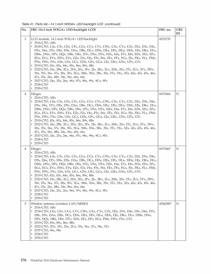
Table 41. Parts list—14.1-inch WXGA+ LED-backlight LCD (continued)
No. FRU (14.1-inch WXGA+ LED-backlight LCD) FRU no. CRUID
3 LCD module, 14.1-inch WXGA+ LED-backlightv 2516-CTO, ABxv 2518-CTO, C4x, C5x, CEx, CFx, CGx, CUx, CVx, CWx, CXx, CYx, CZx, D2x, D3x, D4x,
D5x, D6x, D7x, D8x, D9x, DAx, DBx, DCx, DDx, DEx, DFx, DGx, DHx, DJx, DKx, DLx,DMx, DNx, DPx, DQx, DRx, DSx, DTx, DXx, DYx, DZx, E4x, E7x, E8x, EDx, EEx, EFx,EGx, EUx, EVx, EWx, EYx, EZx, F2x, F4x, F5x, F6x, FEx, FFx, FGx, FJx, FKx, FLx, FMx,FNx, FWx, FXx, G8x, G9x, GCx, GDx, GFx, GGx, GJx, GKx, GNx, GPx, GTx
v 2519-CTO, 82x, 83x, 84x, 85x, 86x, 89x, 8Bxv 2522-CTO, 24x, 2Bx, 2Cx, 2Dx, 2Ex, 2Fx, 2Jx, 2Kx, 2Lx, 2Mx, 2Sx, 2Tx, 2Ux, 2Vx, 2Wx,
30x, 35x, 36x, 37x, 38x, 3Fx, 3Gx, 3Mx, 3Nx, 3Rx, 3Sx, 3Tx, 3Xx, 3Zx, 42x, 43x, 45x, 46x,47x, 25x, 26x, 4Bx, 54x, 56x, 60x, 64x
v 2537-CTO, 24x, 25x, 26x, 96x, 97x, 98x, 99x, 9Cx, 9Fxv 2538-CTOv 2539-CTO
42T0735
4 Hingesv 2516-CTO, ABxv 2518-CTO, C4x, C5x, CEx, CFx, CGx, CUx, CVx, CWx, CXx, CYx, CZx, D2x, D3x, D4x,
D5x, D6x, D7x, D8x, D9x, DAx, DBx, DCx, DDx, DEx, DFx, DGx, DHx, DJx, DKx, DLx,DMx, DNx, DPx, DQx, DRx, DSx, DTx, DXx, DYx, DZx, E4x, E7x, E8x, EDx, EEx, EFx,EGx, EUx, EVx, EWx, EYx, EZx, F2x, F4x, F5x, F6x, FEx, FFx, FGx, FJx, FKx, FLx, FMx,FNx, FWx, FXx, G8x, G9x, GCx, GDx, GFx, GGx, GJx, GKx, GNx, GPx, GTx
v 2519-CTO, 82x, 83x, 84x, 85x, 86x, 89x, 8Bxv 2522-CTO, 24x, 2Bx, 2Cx, 2Dx, 2Ex, 2Fx, 2Jx, 2Kx, 2Lx, 2Mx, 2Sx, 2Tx, 2Ux, 2Vx, 2Wx,
30x, 35x, 36x, 37x, 38x, 3Fx, 3Gx, 3Mx, 3Nx, 3Rx, 3Sx, 3Tx, 3Xx, 3Zx, 42x, 43x, 45x, 46x,47x, 25x, 26x, 4Bx, 54x, 56x, 60x, 64x
v 2537-CTO, 24x, 25x, 26x, 96x, 97x, 98x, 99x, 9Cx, 9Fxv 2538-CTOv 2539-CTO
60Y5466 N
4 Hingesv 2516-CTO, ABxv 2518-CTO, C4x, C5x, CEx, CFx, CGx, CUx, CVx, CWx, CXx, CYx, CZx, D2x, D3x, D4x,
D5x, D6x, D7x, D8x, D9x, DAx, DBx, DCx, DDx, DEx, DFx, DGx, DHx, DJx, DKx, DLx,DMx, DNx, DPx, DQx, DRx, DSx, DTx, DXx, DYx, DZx, E4x, E7x, E8x, EDx, EEx, EFx,EGx, EUx, EVx, EWx, EYx, EZx, F2x, F4x, F5x, F6x, FEx, FFx, FGx, FJx, FKx, FLx, FMx,FNx, FWx, FXx, G8x, G9x, GCx, GDx, GFx, GGx, GJx, GKx, GNx, GPx, GTx
v 2519-CTO, 82x, 83x, 84x, 85x, 86x, 89x, 8Bxv 2522-CTO, 24x, 2Bx, 2Cx, 2Dx, 2Ex, 2Fx, 2Jx, 2Kx, 2Lx, 2Mx, 2Sx, 2Tx, 2Ux, 2Vx, 2Wx,
30x, 35x, 36x, 37x, 38x, 3Fx, 3Gx, 3Mx, 3Nx, 3Rx, 3Sx, 3Tx, 3Xx, 3Zx, 42x, 43x, 45x, 46x,47x, 25x, 26x, 4Bx, 54x, 56x, 60x, 64x
v 2537-CTO, 24x, 25x, 26x, 96x, 97x, 98x, 99x, 9Cx, 9Fxv 2538-CTOv 2539-CTO
60Y5467 N
5 Wireless antenna (wireless LAN/MIMO)v 2516-CTO, ABxv 2518-CTO, CEx, CFx, CUx, CVx, CWx, CXx, CYx, CZx, D2x, D3x, D4x, D5x, D6x, D7x,
D8x, D9x, DAx, DBx, DCx, DDx, DEx, DFx, DGx, DHx, DJx, DKx, DLx, DMx, DNx,DPx, DQx, DRx, DSx, DTx, EDx, EEx, EFx, EGx, FMx, FWx, FXx, GTx
v 2519-CTO, 83x, 85x, 86x, 8Bxv 2522-CTO, 2Dx, 2Fx, 2Sx, 2Ux, 35x, 36x, 37x, 38x, 3Txv 2537-CTO, 96x, 98xv 2538-CTOv 2539-CTO
45M2887 N
176 ThinkPad T410 Hardware Maintenance Manual
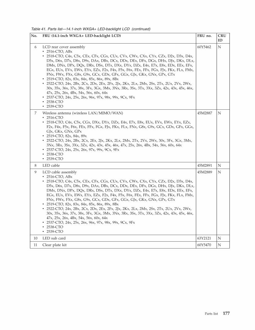
Table 41. Parts list—14.1-inch WXGA+ LED-backlight LCD (continued)
No. FRU (14.1-inch WXGA+ LED-backlight LCD) FRU no. CRUID
6 LCD rear cover assemblyv 2516-CTO, ABxv 2518-CTO, C4x, C5x, CEx, CFx, CGx, CUx, CVx, CWx, CXx, CYx, CZx, D2x, D3x, D4x,
D5x, D6x, D7x, D8x, D9x, DAx, DBx, DCx, DDx, DEx, DFx, DGx, DHx, DJx, DKx, DLx,DMx, DNx, DPx, DQx, DRx, DSx, DTx, DXx, DYx, DZx, E4x, E7x, E8x, EDx, EEx, EFx,EGx, EUx, EVx, EWx, EYx, EZx, F2x, F4x, F5x, F6x, FEx, FFx, FGx, FJx, FKx, FLx, FMx,FNx, FWx, FXx, G8x, G9x, GCx, GDx, GFx, GGx, GJx, GKx, GNx, GPx, GTx
v 2519-CTO, 82x, 83x, 84x, 85x, 86x, 89x, 8Bxv 2522-CTO, 24x, 2Bx, 2Cx, 2Dx, 2Ex, 2Fx, 2Jx, 2Kx, 2Lx, 2Mx, 2Sx, 2Tx, 2Ux, 2Vx, 2Wx,
30x, 35x, 36x, 37x, 38x, 3Fx, 3Gx, 3Mx, 3Nx, 3Rx, 3Sx, 3Tx, 3Xx, 3Zx, 42x, 43x, 45x, 46x,47x, 25x, 26x, 4Bx, 54x, 56x, 60x, 64x
v 2537-CTO, 24x, 25x, 26x, 96x, 97x, 98x, 99x, 9Cx, 9Fxv 2538-CTOv 2539-CTO
60Y5462 N
7 Wireless antenna (wireless LAN/MIMO/WAN)v 2516-CTOv 2518-CTO, C4x, C5x, CGx, DXx, DYx, DZx, E4x, E7x, E8x, EUx, EVx, EWx, EYx, EZx,
F2x, F4x, F5x, F6x, FEx, FFx, FGx, FJx, FKx, FLx, FNx, G8x, G9x, GCx, GDx, GFx, GGx,GJx, GKx, GNx, GPx
v 2519-CTO, 82x, 84x, 89xv 2522-CTO, 24x, 2Bx, 2Cx, 2Ex, 2Jx, 2Kx, 2Lx, 2Mx, 2Tx, 2Vx, 2Wx, 30x, 3Fx, 3Gx, 3Mx,
3Nx, 3Rx, 3Sx, 3Xx, 3Zx, 42x, 43x, 45x, 46x, 47x, 25x, 26x, 4Bx, 54x, 56x, 60x, 64xv 2537-CTO, 24x, 25x, 26x, 97x, 99x, 9Cx, 9Fxv 2538-CTOv 2539-CTO
45M2887 N
8 LED cable 45M2891 N
9 LCD cable assemblyv 2516-CTO, ABxv 2518-CTO, C4x, C5x, CEx, CFx, CGx, CUx, CVx, CWx, CXx, CYx, CZx, D2x, D3x, D4x,
D5x, D6x, D7x, D8x, D9x, DAx, DBx, DCx, DDx, DEx, DFx, DGx, DHx, DJx, DKx, DLx,DMx, DNx, DPx, DQx, DRx, DSx, DTx, DXx, DYx, DZx, E4x, E7x, E8x, EDx, EEx, EFx,EGx, EUx, EVx, EWx, EYx, EZx, F2x, F4x, F5x, F6x, FEx, FFx, FGx, FJx, FKx, FLx, FMx,FNx, FWx, FXx, G8x, G9x, GCx, GDx, GFx, GGx, GJx, GKx, GNx, GPx, GTx
v 2519-CTO, 82x, 83x, 84x, 85x, 86x, 89x, 8Bxv 2522-CTO, 24x, 2Bx, 2Cx, 2Dx, 2Ex, 2Fx, 2Jx, 2Kx, 2Lx, 2Mx, 2Sx, 2Tx, 2Ux, 2Vx, 2Wx,
30x, 35x, 36x, 37x, 38x, 3Fx, 3Gx, 3Mx, 3Nx, 3Rx, 3Sx, 3Tx, 3Xx, 3Zx, 42x, 43x, 45x, 46x,47x, 25x, 26x, 4Bx, 54x, 56x, 60x, 64x
v 2537-CTO, 24x, 25x, 26x, 96x, 97x, 98x, 99x, 9Cx, 9Fxv 2538-CTOv 2539-CTO
45M2889 N
10 LED sub card 63Y2121 N
11 Clear plate kit 60Y5470 N
Parts list 177
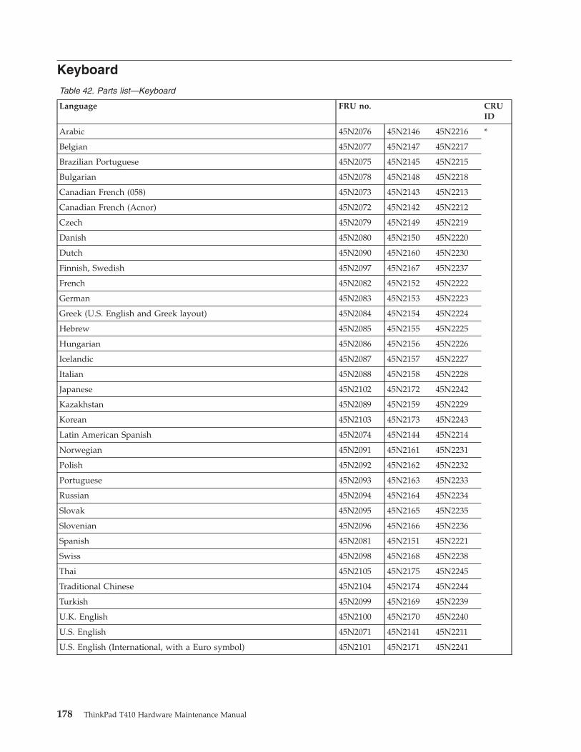
KeyboardTable 42. Parts list—Keyboard
Language FRU no. CRUID
Arabic 45N2076 45N2146 45N2216 *
Belgian 45N2077 45N2147 45N2217
Brazilian Portuguese 45N2075 45N2145 45N2215
Bulgarian 45N2078 45N2148 45N2218
Canadian French (058) 45N2073 45N2143 45N2213
Canadian French (Acnor) 45N2072 45N2142 45N2212
Czech 45N2079 45N2149 45N2219
Danish 45N2080 45N2150 45N2220
Dutch 45N2090 45N2160 45N2230
Finnish, Swedish 45N2097 45N2167 45N2237
French 45N2082 45N2152 45N2222
German 45N2083 45N2153 45N2223
Greek (U.S. English and Greek layout) 45N2084 45N2154 45N2224
Hebrew 45N2085 45N2155 45N2225
Hungarian 45N2086 45N2156 45N2226
Icelandic 45N2087 45N2157 45N2227
Italian 45N2088 45N2158 45N2228
Japanese 45N2102 45N2172 45N2242
Kazakhstan 45N2089 45N2159 45N2229
Korean 45N2103 45N2173 45N2243
Latin American Spanish 45N2074 45N2144 45N2214
Norwegian 45N2091 45N2161 45N2231
Polish 45N2092 45N2162 45N2232
Portuguese 45N2093 45N2163 45N2233
Russian 45N2094 45N2164 45N2234
Slovak 45N2095 45N2165 45N2235
Slovenian 45N2096 45N2166 45N2236
Spanish 45N2081 45N2151 45N2221
Swiss 45N2098 45N2168 45N2238
Thai 45N2105 45N2175 45N2245
Traditional Chinese 45N2104 45N2174 45N2244
Turkish 45N2099 45N2169 45N2239
U.K. English 45N2100 45N2170 45N2240
U.S. English 45N2071 45N2141 45N2211
U.S. English (International, with a Euro symbol) 45N2101 45N2171 45N2241
178 ThinkPad T410 Hardware Maintenance Manual
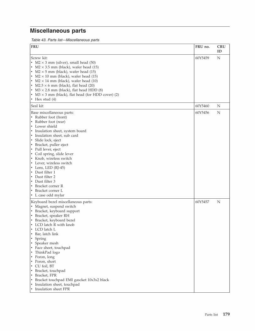
Miscellaneous partsTable 43. Parts list—Miscellaneous parts
FRU FRU no. CRUID
Screw kit:v M2 × 3 mm (silver), small head (50)v M2 × 3.5 mm (black), wafer head (15)v M2 × 5 mm (black), wafer head (15)v M2 × 10 mm (black), wafer head (15)v M2 × 14 mm (black), wafer head (10)v M2.5 × 6 mm (black), flat head (20)v M3 × 2.8 mm (black), flat head HDD (8)v M3 × 3 mm (black), flat head (for HDD cover) (2)v Hex stud (4)
60Y5459 N
Seal kit 60Y5460 N
Base miscellaneous parts:v Rubber foot (front)v Rubber foot (rear)v Lower shieldv Insulation sheet, system boardv Insulation sheet, sub cardv Slide lock, ejectv Bracket, puller ejectv Pull lever, ejectv Coil spring, slide leverv Knob, wireless switchv Lever, wireless switchv Lens, LED (RJ-45)v Dust filter 1v Dust filter 2v Dust filter 3v Bracket corner Rv Bracket corner Lv L case odd mylar
60Y5456 N
Keyboard bezel miscellaneous parts:v Magnet, suspend switchv Bracket, keyboard supportv Bracket, speaker RHv Bracket, keyboard bezelv LCD latch R with knobv LCD latch Lv Bar, latch linkv Springv Speaker meshv Face sheet, touchpadv ThinkPad logov Poron, longv Poron, shortv CU foil, BTv Bracket, touchpadv Bracket, FPRv Bracket touchpad EMI gascket 10x3x2 blackv Insulation sheet, touchpadv Insulation sheet FPR
60Y5457 N
Parts list 179
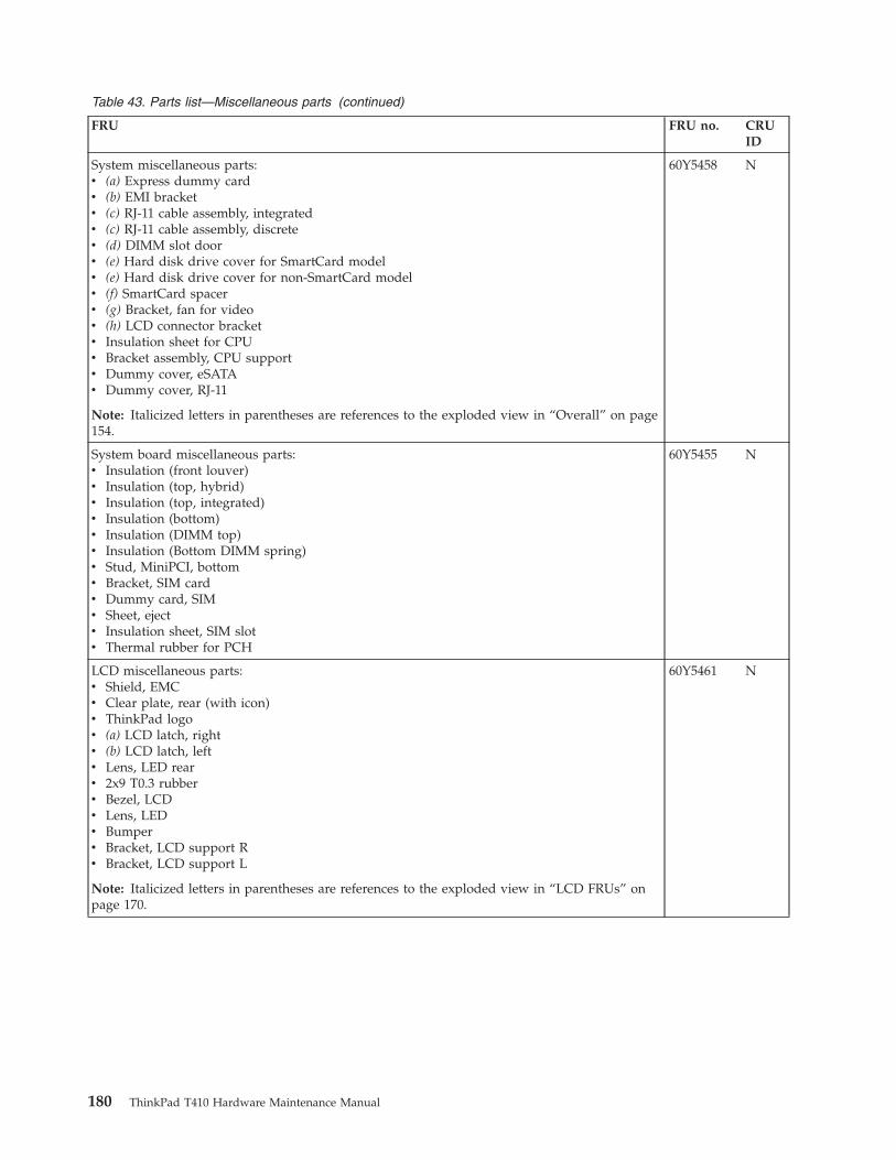
Table 43. Parts list—Miscellaneous parts (continued)
FRU FRU no. CRUID
System miscellaneous parts:v (a) Express dummy cardv (b) EMI bracketv (c) RJ-11 cable assembly, integratedv (c) RJ-11 cable assembly, discretev (d) DIMM slot doorv (e) Hard disk drive cover for SmartCard modelv (e) Hard disk drive cover for non-SmartCard modelv (f) SmartCard spacerv (g) Bracket, fan for videov (h) LCD connector bracketv Insulation sheet for CPUv Bracket assembly, CPU supportv Dummy cover, eSATAv Dummy cover, RJ-11
Note: Italicized letters in parentheses are references to the exploded view in “Overall” on page154.
60Y5458 N
System board miscellaneous parts:v Insulation (front louver)v Insulation (top, hybrid)v Insulation (top, integrated)v Insulation (bottom)v Insulation (DIMM top)v Insulation (Bottom DIMM spring)v Stud, MiniPCI, bottomv Bracket, SIM cardv Dummy card, SIMv Sheet, ejectv Insulation sheet, SIM slotv Thermal rubber for PCH
60Y5455 N
LCD miscellaneous parts:v Shield, EMCv Clear plate, rear (with icon)v ThinkPad logov (a) LCD latch, rightv (b) LCD latch, leftv Lens, LED rearv 2x9 T0.3 rubberv Bezel, LCDv Lens, LEDv Bumperv Bracket, LCD support Rv Bracket, LCD support L
Note: Italicized letters in parentheses are references to the exploded view in “LCD FRUs” onpage 170.
60Y5461 N
180 ThinkPad T410 Hardware Maintenance Manual
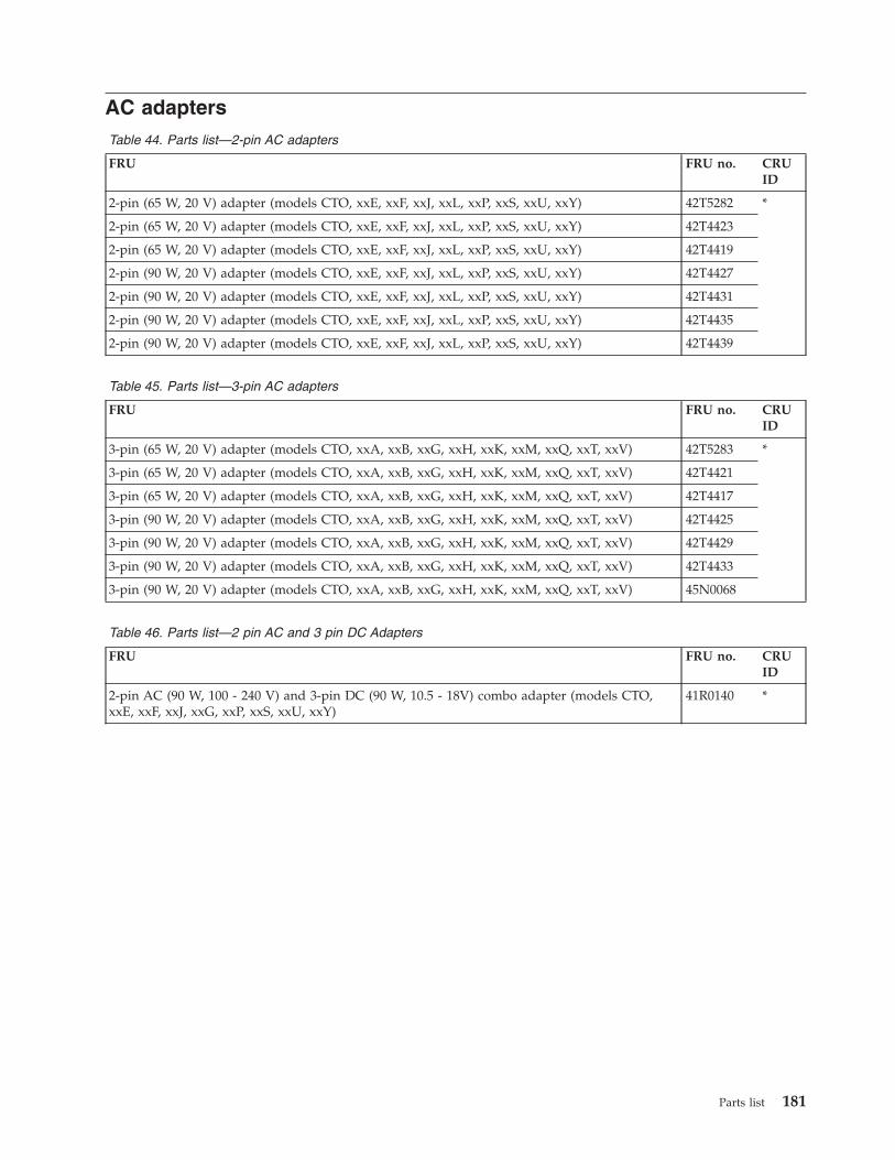
AC adaptersTable 44. Parts list—2-pin AC adapters
FRU FRU no. CRUID
2-pin (65 W, 20 V) adapter (models CTO, xxE, xxF, xxJ, xxL, xxP, xxS, xxU, xxY) 42T5282 *
2-pin (65 W, 20 V) adapter (models CTO, xxE, xxF, xxJ, xxL, xxP, xxS, xxU, xxY) 42T4423
2-pin (65 W, 20 V) adapter (models CTO, xxE, xxF, xxJ, xxL, xxP, xxS, xxU, xxY) 42T4419
2-pin (90 W, 20 V) adapter (models CTO, xxE, xxF, xxJ, xxL, xxP, xxS, xxU, xxY) 42T4427
2-pin (90 W, 20 V) adapter (models CTO, xxE, xxF, xxJ, xxL, xxP, xxS, xxU, xxY) 42T4431
2-pin (90 W, 20 V) adapter (models CTO, xxE, xxF, xxJ, xxL, xxP, xxS, xxU, xxY) 42T4435
2-pin (90 W, 20 V) adapter (models CTO, xxE, xxF, xxJ, xxL, xxP, xxS, xxU, xxY) 42T4439
Table 45. Parts list—3-pin AC adapters
FRU FRU no. CRUID
3-pin (65 W, 20 V) adapter (models CTO, xxA, xxB, xxG, xxH, xxK, xxM, xxQ, xxT, xxV) 42T5283 *
3-pin (65 W, 20 V) adapter (models CTO, xxA, xxB, xxG, xxH, xxK, xxM, xxQ, xxT, xxV) 42T4421
3-pin (65 W, 20 V) adapter (models CTO, xxA, xxB, xxG, xxH, xxK, xxM, xxQ, xxT, xxV) 42T4417
3-pin (90 W, 20 V) adapter (models CTO, xxA, xxB, xxG, xxH, xxK, xxM, xxQ, xxT, xxV) 42T4425
3-pin (90 W, 20 V) adapter (models CTO, xxA, xxB, xxG, xxH, xxK, xxM, xxQ, xxT, xxV) 42T4429
3-pin (90 W, 20 V) adapter (models CTO, xxA, xxB, xxG, xxH, xxK, xxM, xxQ, xxT, xxV) 42T4433
3-pin (90 W, 20 V) adapter (models CTO, xxA, xxB, xxG, xxH, xxK, xxM, xxQ, xxT, xxV) 45N0068
Table 46. Parts list—2 pin AC and 3 pin DC Adapters
FRU FRU no. CRUID
2-pin AC (90 W, 100 - 240 V) and 3-pin DC (90 W, 10.5 - 18V) combo adapter (models CTO,xxE, xxF, xxJ, xxG, xxP, xxS, xxU, xxY)
41R0140 *
Parts list 181
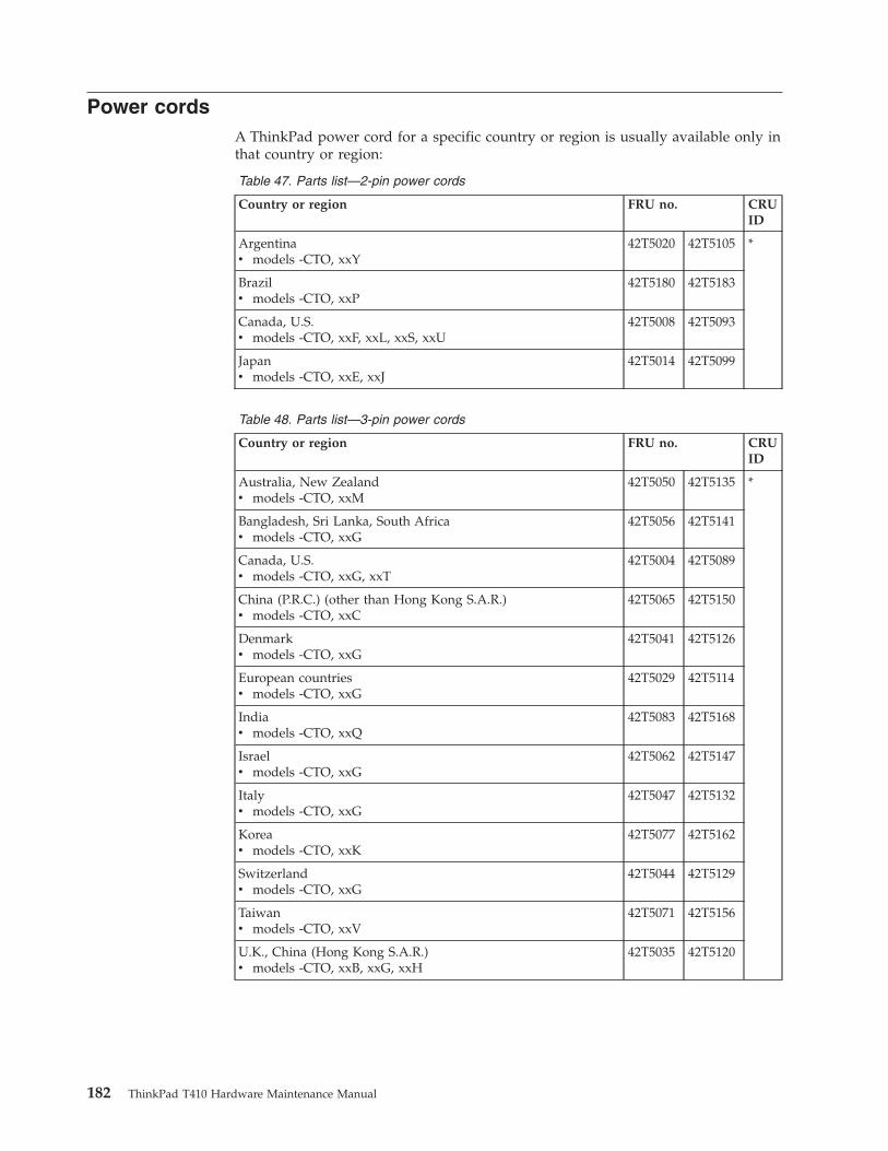
Power cordsA ThinkPad power cord for a specific country or region is usually available only inthat country or region:
Table 47. Parts list—2-pin power cords
Country or region FRU no. CRUID
Argentinav models -CTO, xxY
42T5020 42T5105 *
Brazilv models -CTO, xxP
42T5180 42T5183
Canada, U.S.v models -CTO, xxF, xxL, xxS, xxU
42T5008 42T5093
Japanv models -CTO, xxE, xxJ
42T5014 42T5099
Table 48. Parts list—3-pin power cords
Country or region FRU no. CRUID
Australia, New Zealandv models -CTO, xxM
42T5050 42T5135 *
Bangladesh, Sri Lanka, South Africav models -CTO, xxG
42T5056 42T5141
Canada, U.S.v models -CTO, xxG, xxT
42T5004 42T5089
China (P.R.C.) (other than Hong Kong S.A.R.)v models -CTO, xxC
42T5065 42T5150
Denmarkv models -CTO, xxG
42T5041 42T5126
European countriesv models -CTO, xxG
42T5029 42T5114
Indiav models -CTO, xxQ
42T5083 42T5168
Israelv models -CTO, xxG
42T5062 42T5147
Italyv models -CTO, xxG
42T5047 42T5132
Koreav models -CTO, xxK
42T5077 42T5162
Switzerlandv models -CTO, xxG
42T5044 42T5129
Taiwanv models -CTO, xxV
42T5071 42T5156
U.K., China (Hong Kong S.A.R.)v models -CTO, xxB, xxG, xxH
42T5035 42T5120
182 ThinkPad T410 Hardware Maintenance Manual
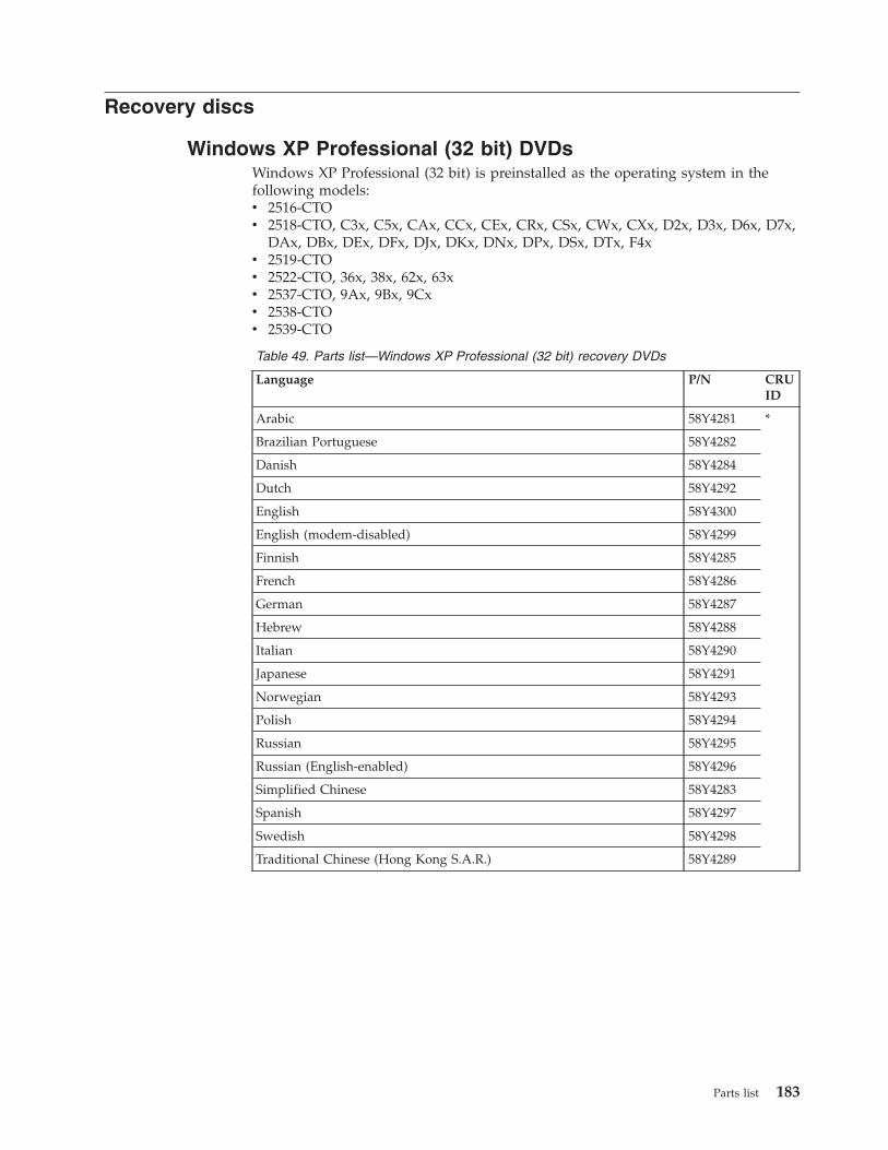
Recovery discs
Windows XP Professional (32 bit) DVDsWindows XP Professional (32 bit) is preinstalled as the operating system in thefollowing models:v 2516-CTOv 2518-CTO, C3x, C5x, CAx, CCx, CEx, CRx, CSx, CWx, CXx, D2x, D3x, D6x, D7x,
DAx, DBx, DEx, DFx, DJx, DKx, DNx, DPx, DSx, DTx, F4xv 2519-CTOv 2522-CTO, 36x, 38x, 62x, 63xv 2537-CTO, 9Ax, 9Bx, 9Cxv 2538-CTOv 2539-CTO
Table 49. Parts list—Windows XP Professional (32 bit) recovery DVDs
Language P/N CRUID
Arabic 58Y4281 *
Brazilian Portuguese 58Y4282
Danish 58Y4284
Dutch 58Y4292
English 58Y4300
English (modem-disabled) 58Y4299
Finnish 58Y4285
French 58Y4286
German 58Y4287
Hebrew 58Y4288
Italian 58Y4290
Japanese 58Y4291
Norwegian 58Y4293
Polish 58Y4294
Russian 58Y4295
Russian (English-enabled) 58Y4296
Simplified Chinese 58Y4283
Spanish 58Y4297
Swedish 58Y4298
Traditional Chinese (Hong Kong S.A.R.) 58Y4289
Parts list 183
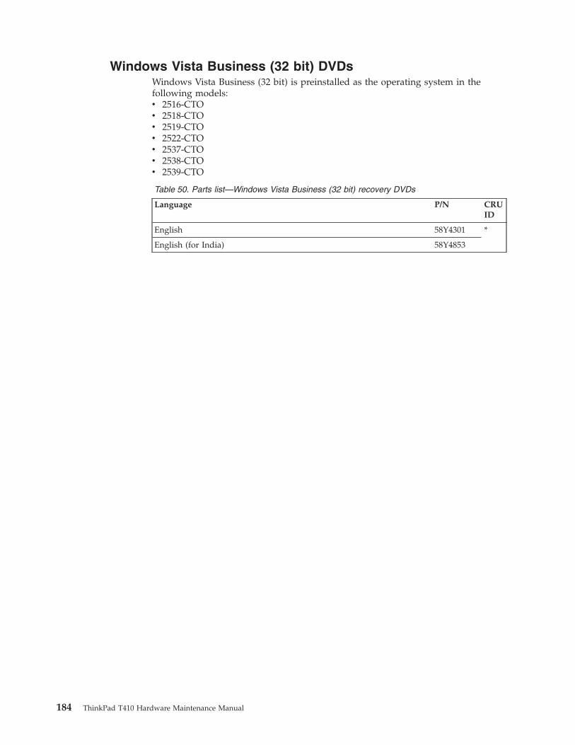
Windows Vista Business (32 bit) DVDsWindows Vista Business (32 bit) is preinstalled as the operating system in thefollowing models:v 2516-CTOv 2518-CTOv 2519-CTOv 2522-CTOv 2537-CTOv 2538-CTOv 2539-CTO
Table 50. Parts list—Windows Vista Business (32 bit) recovery DVDs
Language P/N CRUID
English 58Y4301 *
English (for India) 58Y4853
184 ThinkPad T410 Hardware Maintenance Manual
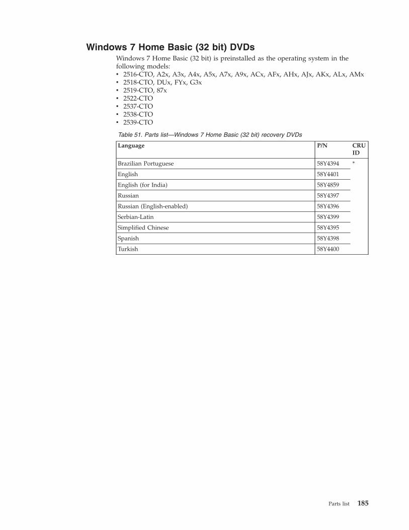
Windows 7 Home Basic (32 bit) DVDsWindows 7 Home Basic (32 bit) is preinstalled as the operating system in thefollowing models:v 2516-CTO, A2x, A3x, A4x, A5x, A7x, A9x, ACx, AFx, AHx, AJx, AKx, ALx, AMxv 2518-CTO, DUx, FYx, G3xv 2519-CTO, 87xv 2522-CTOv 2537-CTOv 2538-CTOv 2539-CTO
Table 51. Parts list—Windows 7 Home Basic (32 bit) recovery DVDs
Language P/N CRUID
Brazilian Portuguese 58Y4394 *
English 58Y4401
English (for India) 58Y4859
Russian 58Y4397
Russian (English-enabled) 58Y4396
Serbian-Latin 58Y4399
Simplified Chinese 58Y4395
Spanish 58Y4398
Turkish 58Y4400
Parts list 185
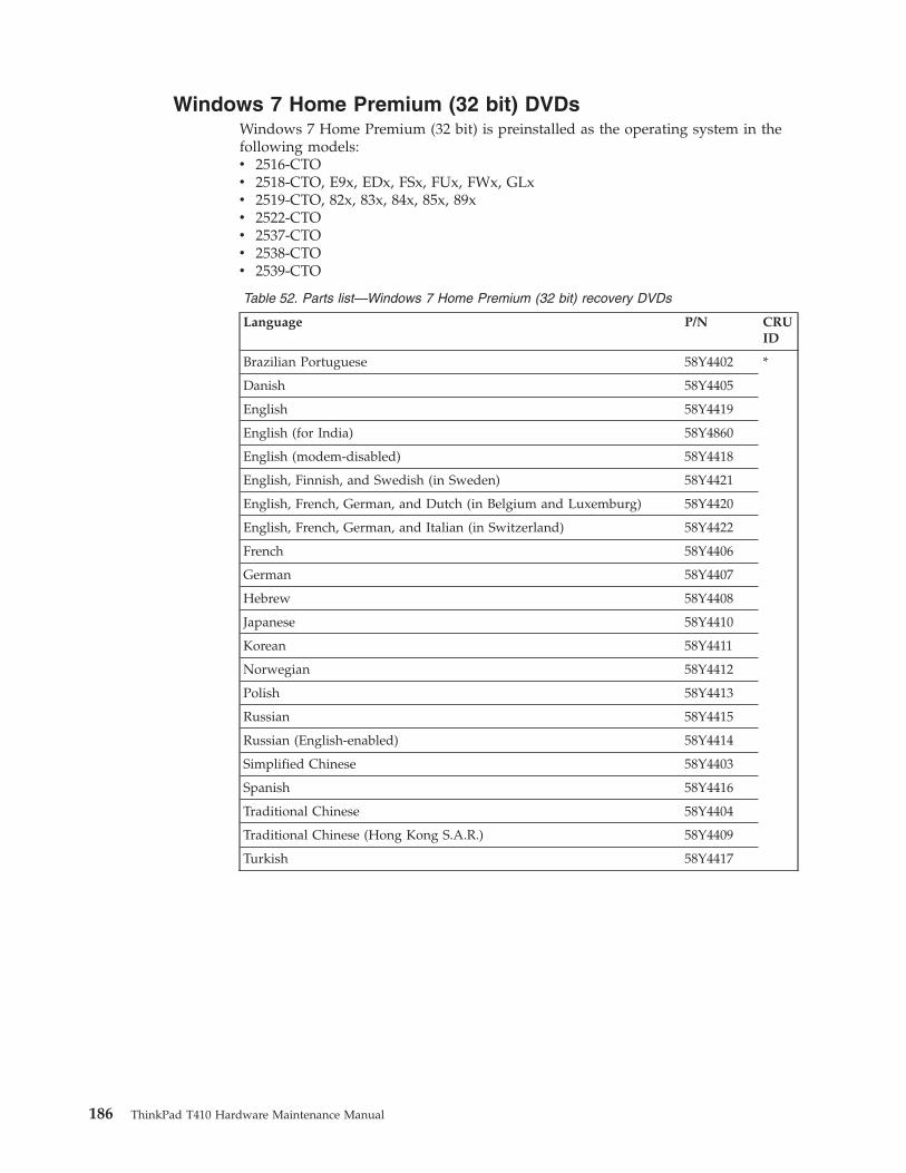
Windows 7 Home Premium (32 bit) DVDsWindows 7 Home Premium (32 bit) is preinstalled as the operating system in thefollowing models:v 2516-CTOv 2518-CTO, E9x, EDx, FSx, FUx, FWx, GLxv 2519-CTO, 82x, 83x, 84x, 85x, 89xv 2522-CTOv 2537-CTOv 2538-CTOv 2539-CTO
Table 52. Parts list—Windows 7 Home Premium (32 bit) recovery DVDs
Language P/N CRUID
Brazilian Portuguese 58Y4402 *
Danish 58Y4405
English 58Y4419
English (for India) 58Y4860
English (modem-disabled) 58Y4418
English, Finnish, and Swedish (in Sweden) 58Y4421
English, French, German, and Dutch (in Belgium and Luxemburg) 58Y4420
English, French, German, and Italian (in Switzerland) 58Y4422
French 58Y4406
German 58Y4407
Hebrew 58Y4408
Japanese 58Y4410
Korean 58Y4411
Norwegian 58Y4412
Polish 58Y4413
Russian 58Y4415
Russian (English-enabled) 58Y4414
Simplified Chinese 58Y4403
Spanish 58Y4416
Traditional Chinese 58Y4404
Traditional Chinese (Hong Kong S.A.R.) 58Y4409
Turkish 58Y4417
186 ThinkPad T410 Hardware Maintenance Manual
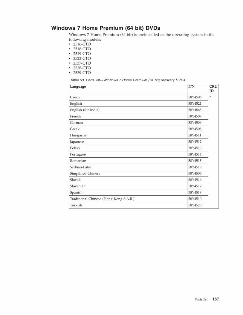
Windows 7 Home Premium (64 bit) DVDsWindows 7 Home Premium (64 bit) is preinstalled as the operating system in thefollowing models:v 2516-CTOv 2518-CTOv 2519-CTOv 2522-CTOv 2537-CTOv 2538-CTOv 2539-CTO
Table 53. Parts list—Windows 7 Home Premium (64 bit) recovery DVDs
Language P/N CRUID
Czech 58Y4506 *
English 58Y4521
English (for India) 58Y4865
French 58Y4507
German 58Y4509
Greek 58Y4508
Hungarian 58Y4511
Japanese 58Y4512
Polish 58Y4513
Portugese 58Y4514
Romanian 58Y4515
Serbian-Latin 58Y4519
Simplified Chinese 58Y4505
Slovak 58Y4516
Slovenian 58Y4517
Spanish 58Y4518
Traditional Chinese (Hong Kong S.A.R.) 58Y4510
Turkish 58Y4520
Parts list 187
Windows 7 Professional (32 bit) DVDsWindows 7 Professional (32 bit) is preinstalled as the operating system in thefollowing models:v 2516-CTO, A6x, A8x, AAx, ADx, AEx, AGx, ANxv 2518-CTO, C2x, C4x, C6x, C7x, C8x, C9x, CBx, CDx, CFx, CGx, CHx, CJx, CKx,
CLx, CMx, CNx, CPx, CQx, CUx, CVx, CYx, CZx, D4x, D5x, D8x, D9x, DCx,DDx, DGx, DHx, DLx, DMx, DQx, DRx, DVx, DWx, DXx, DYx, DZx, E4x, E7x,ELx, EMx, ENx, EPx, EQx, ERx, ESx, EXx, EYx, EZx, F2x, F3x, F5x, F6x, FHx,FJx, FKx, FLx, FMx, FNx, FZx, G2x, G4x, G5x, G6x, GBx, GCx, GDx, GHx, GJx,GKx, GMx, GNx, GPx, GQx, GRx, GSx, GTx
v 2519-CTO, 86x, 88x, 8Ax, 8Bxv 2522-CTO, 30x, 60x, 22x, 23x, 24x, 2Ax, 2Bx, 2Cx, 2Dx, 2Ex, 2Fx, 2Gx, 2Hx, 2Jx,
2Kx, 2Lx, 2Mx, 2Nx, 2Px, 2Qx, 2Rx, 2Sx, 2Tx, 2Ux, 2Vx, 2Wx, 2Xx, 2Yx, 2Zx, 32x,33x, 34x, 35x, 37x, 39x, 3Ax, 3Bx, 3Cx, 3Dx, 3Ex, 3Hx, 3Jx, 3Lx, 3Qx, 3Rx, 3Sx,3Vx, 3Wx, 3Xx, 44x, 45x, 46x, 47x, 25x, 48x, 49x, 26x, 4Ax, 4Bx, 52x, 53x, 54x, 55x,56x, 64x
v 2537-CTO, 22x, 23x, 24x, 25x, 26x, 92x, 93x, 94x, 95x, 96x, 97x, 98x, 99x, 9Dx, 9Ex,9Fx
v 2538-CTOv 2539-CTO
188 ThinkPad T410 Hardware Maintenance Manual
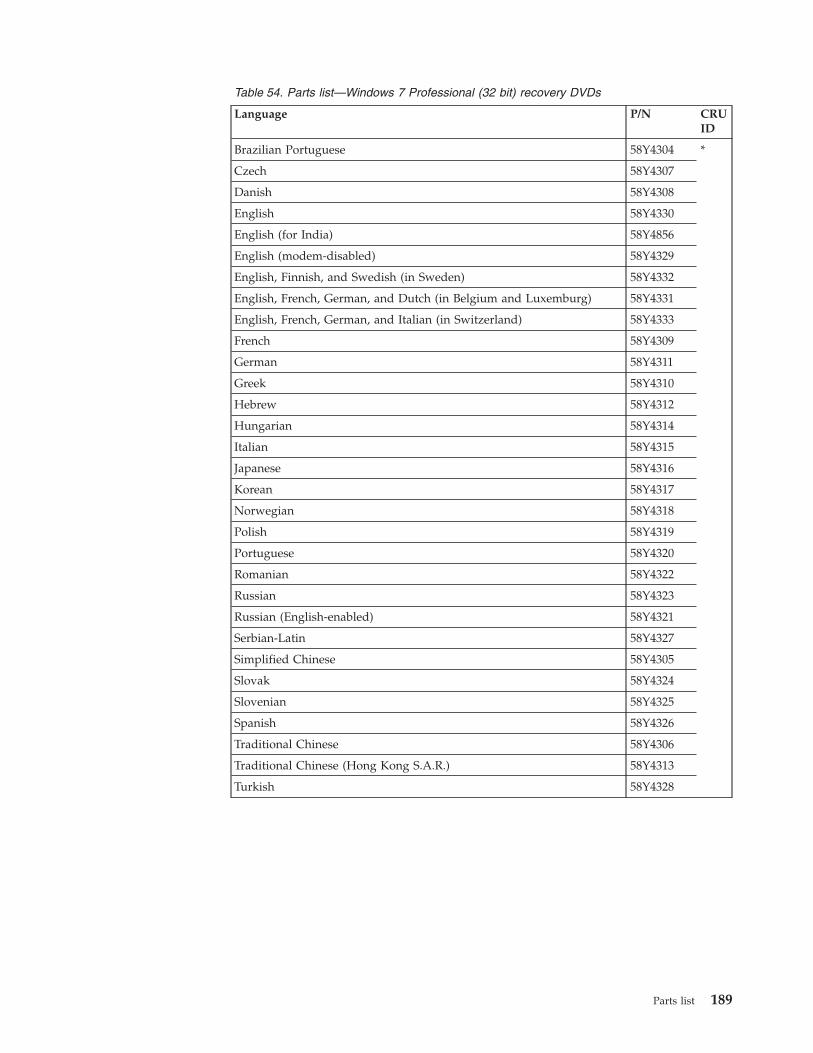
Table 54. Parts list—Windows 7 Professional (32 bit) recovery DVDs
Language P/N CRUID
Brazilian Portuguese 58Y4304 *
Czech 58Y4307
Danish 58Y4308
English 58Y4330
English (for India) 58Y4856
English (modem-disabled) 58Y4329
English, Finnish, and Swedish (in Sweden) 58Y4332
English, French, German, and Dutch (in Belgium and Luxemburg) 58Y4331
English, French, German, and Italian (in Switzerland) 58Y4333
French 58Y4309
German 58Y4311
Greek 58Y4310
Hebrew 58Y4312
Hungarian 58Y4314
Italian 58Y4315
Japanese 58Y4316
Korean 58Y4317
Norwegian 58Y4318
Polish 58Y4319
Portuguese 58Y4320
Romanian 58Y4322
Russian 58Y4323
Russian (English-enabled) 58Y4321
Serbian-Latin 58Y4327
Simplified Chinese 58Y4305
Slovak 58Y4324
Slovenian 58Y4325
Spanish 58Y4326
Traditional Chinese 58Y4306
Traditional Chinese (Hong Kong S.A.R.) 58Y4313
Turkish 58Y4328
Parts list 189
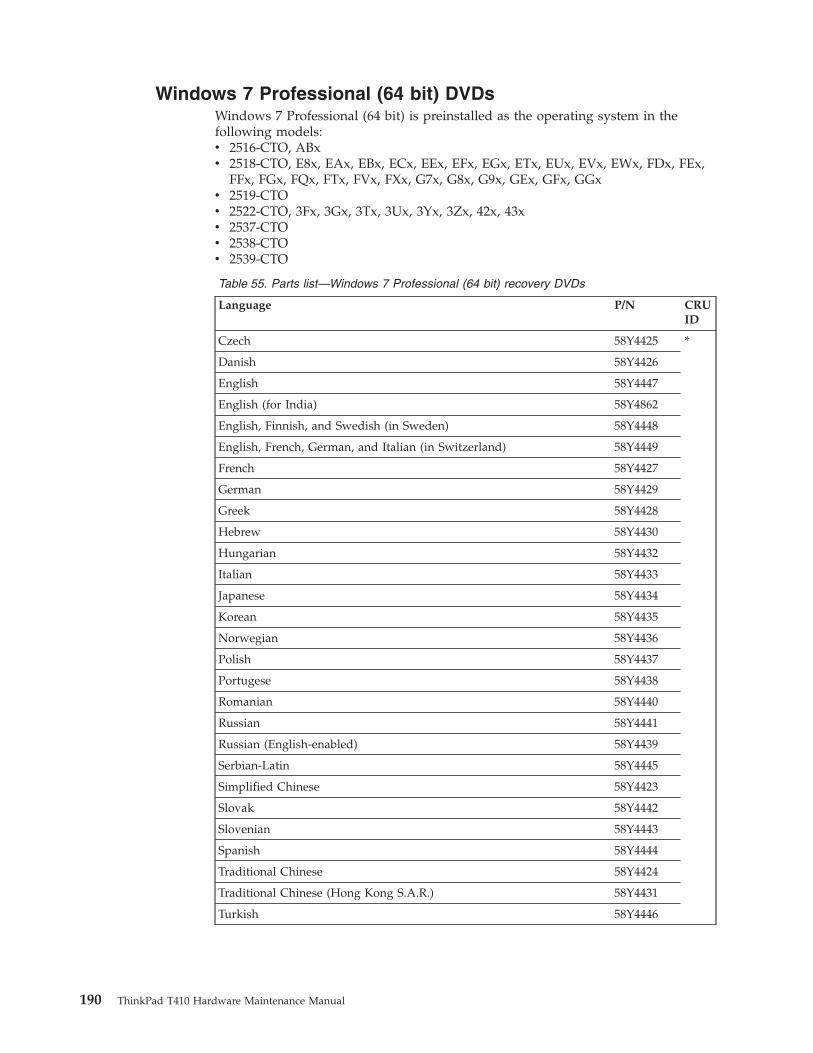
Windows 7 Professional (64 bit) DVDsWindows 7 Professional (64 bit) is preinstalled as the operating system in thefollowing models:v 2516-CTO, ABxv 2518-CTO, E8x, EAx, EBx, ECx, EEx, EFx, EGx, ETx, EUx, EVx, EWx, FDx, FEx,
FFx, FGx, FQx, FTx, FVx, FXx, G7x, G8x, G9x, GEx, GFx, GGxv 2519-CTOv 2522-CTO, 3Fx, 3Gx, 3Tx, 3Ux, 3Yx, 3Zx, 42x, 43xv 2537-CTOv 2538-CTOv 2539-CTO
Table 55. Parts list—Windows 7 Professional (64 bit) recovery DVDs
Language P/N CRUID
Czech 58Y4425 *
Danish 58Y4426
English 58Y4447
English (for India) 58Y4862
English, Finnish, and Swedish (in Sweden) 58Y4448
English, French, German, and Italian (in Switzerland) 58Y4449
French 58Y4427
German 58Y4429
Greek 58Y4428
Hebrew 58Y4430
Hungarian 58Y4432
Italian 58Y4433
Japanese 58Y4434
Korean 58Y4435
Norwegian 58Y4436
Polish 58Y4437
Portugese 58Y4438
Romanian 58Y4440
Russian 58Y4441
Russian (English-enabled) 58Y4439
Serbian-Latin 58Y4445
Simplified Chinese 58Y4423
Slovak 58Y4442
Slovenian 58Y4443
Spanish 58Y4444
Traditional Chinese 58Y4424
Traditional Chinese (Hong Kong S.A.R.) 58Y4431
Turkish 58Y4446
190 ThinkPad T410 Hardware Maintenance Manual
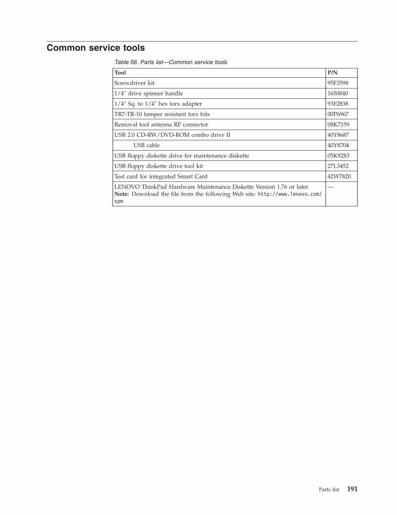
Common service toolsTable 56. Parts list—Common service tools
Tool P/N
Screwdriver kit 95F3598
1/4″ drive spinner handle 1650840
1/4″ Sq. to 1/4″ hex torx adapter 93F2838
TR7-TR-10 tamper resistant torx bits 00P6967
Removal tool antenna RF connector 08K7159
USB 2.0 CD-RW/DVD-ROM combo drive II 40Y8687
USB cable 40Y8704
USB floppy diskette drive for maintenance diskette 05K9283
USB floppy diskette drive tool kit 27L3452
Test card for integrated Smart Card 42W7820
LENOVO ThinkPad Hardware Maintenance Diskette Version 1.76 or laterNote: Download the file from the following Web site: http://www.lenovo.com/spm
—
Parts list 191

192 ThinkPad T410 Hardware Maintenance Manual
Notices
Lenovo may not offer the products, services, or features discussed in thisdocument in all countries. Consult your local Lenovo representative forinformation on the products and services currently available in your area. Anyreference to a Lenovo product, program, or service is not intended to state orimply that only that Lenovo product, program, or service may be used. Anyfunctionally equivalent product, program, or service that does not infringe anyLenovo intellectual property right may be used instead. However, it is the user’sresponsibility to evaluate and verify the operation of any other product, program,or service.
Lenovo may have patents or pending patent applications covering subject matterdescribed in this document. The furnishing of this document does not give youany license to these patents. You can send license inquiries, in writing, to:
Lenovo (United States), Inc.1009 Think Place - Building OneMorrisville, NC 27560U.S.A.Attention: Lenovo Director of Licensing
LENOVO GROUP LTD. PROVIDES THIS PUBLICATION “AS IS” WITHOUTWARRANTY OF ANY KIND, EITHER EXPRESS OR IMPLIED, INCLUDING, BUTNOT LIMITED TO, THE IMPLIED WARRANTIES OF NON-INFRINGEMENT,MERCHANTABILITY OR FITNESS FOR A PARTICULAR PURPOSE. Somejurisdictions do not allow disclaimer of express or implied warranties in certaintransactions, therefore, this statement may not apply to you.
This information could include technical inaccuracies or typographical errors.Changes are periodically made to the information herein; these changes will beincorporated in new editions of the publication. Lenovo may make improvementsand/or changes in the product(s) and/or the program(s) described in thispublication at any time without notice.
The products described in this document are not intended for use in implantationor other life support applications where malfunction may result in injury or deathto persons. The information contained in this document does not affect or changeLenovo product specifications or warranties. Nothing in this document shalloperate as an express or implied license or indemnity under the intellectualproperty rights of Lenovo or third parties. All information contained in thisdocument was obtained in specific environments and is presented as anillustration. The result obtained in other operating environments may vary.
Lenovo may use or distribute any of the information you supply in any way itbelieves appropriate without incurring any obligation to you.
Any references in this publication to non-Lenovo Web sites are provided forconvenience only and do not in any manner serve as an endorsement of those Websites. The materials at those Web sites are not part of the materials for this Lenovoproduct, and use of those Web sites is at your own risk.
Any performance data contained herein was determined in a controlledenvironment. Therefore, the result obtained in other operating environments may
© Copyright Lenovo 2010 193
vary significantly. Some measurements may have been made on development-levelsystems and there is no guarantee that these measurements will be the same ongenerally available systems. Furthermore, some measurements may have beenestimated through extrapolation. Actual results may vary. Users of this documentshould verify the applicable data for their specific environment.
TrademarksThe following terms are trademarks of Lenovo in the United States, other countriesor both:
Active Protection SystemLenovo®
Rescue and Recovery®
ThinkLight®
ThinkPad®
ThinkVantage®
TrackPoint®
UltrabayUltraNav®
IBM® (used under license) is trademark of the International Business MachinesCorporation in the United States, other countries, or both:
The following terms are trademarks of Microsoft Corporation in the United States,other countries, or both:
Windows®
Windows Vista®
The following terms are trademarks of Intel Corporation or its subsidiaries in theUnited States, other countries, or both:
Intel®
Intel® Centrino®
Intel® Core
Other company, product, or service names may be the trademarks or service marksof others.
194 ThinkPad T410 Hardware Maintenance Manual


Part Number: 63Y0535
(1P) P/N: 63Y0535
Recommended