|L|CTRIC POW|n 8 lST[m$
E L S E V I E R Electric Power Systems Research, 29 (1994) 27-33
Use of an expert system shell to develop a power plant simulator for monitoring and fault diagnosis
Alvin C.B. Wong, H.K. Ho and C.Y. Teo Division of Electrical Engineering, School of Electrical and Electronic Engineering, Nanyang Technological University,
Nanyang Avenue, Singapore 2263 (Singapore)
(Received May 5. 1993; accepted October 6, 1993)
Abstract
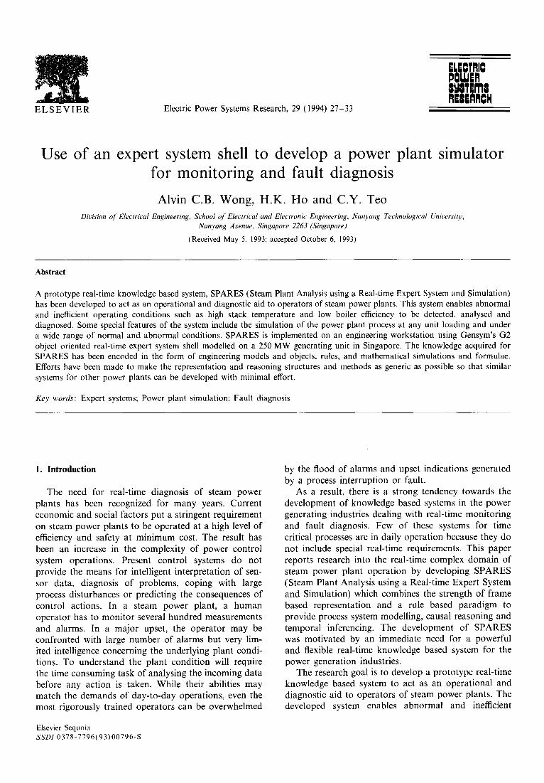
A prototype real-time knowledge based system, SPARES (Steam Plant Analysis using a Real-time Expert System and Simulation) has been developed to act as an operational and diagnostic aid to operators of steam power plants. This system enables abnormal and inefficient operating conditions such as high stack temperature and low boiler efficiency to be detected, analysed and diagnosed. Some special features of the system include the simulation of the power plant process at any unit loading and under a wide range of normal and abnormal conditions. SPARES is implemented on an engineering workstation using Gensym's G2 object oriented real-time expert system shell modelled on a 250 MW generating unit in Singapore. The knowledge acquired for SPARES has been encoded in the form of engineering models and objects, rules, and mathematical simulations and formulae. Efforts have been made to make the representation and reasoning structures and methods as generic as possible so that similar systems for other power plants can be developed with minimal effort.
Key words': Expert systems; Power plant simulation; Fault diagnosis
1. Introduction
The need for real-time diagnosis of steam power plants has been recognized for many years. Current economic and social factors put a stringent requirement on steam power plants to be operated at a high level of efficiency and safety at minimum cost. The result has been an increase in the complexity of power control system operations. Present control systems do not provide the means for intelligent interpretation of sen- sor data, diagnosis of problems, coping with large process disturbances or predicting the consequences of control actions. In a steam power plant, a human operator has to monitor several hundred measurements and alarms. In a major upset, the operator may be confronted with large number of alarms but very lim- ited intelligence concerning the underlying plant condi- tions. To understand the plant condition will require the time consuming task of analysing the incoming data before any action is taken. While their abilities may match the demands of day-to-day operations, even the most rigorously trained operators can be overwhelmed
Elsevier Sequoia SSD1 0378-7796(93)00796-S
by the flood of alarms and upset indications generated by a process interruption or fault.
As a result, there is a strong tendency towards the development of knowledge based systems in the power generating industries dealing with real-time monitoring and fault diagnosis. Few of these systems for time critical processes are in daily operation because they do not include special real-time requirements. This paper reports research into the real-time complex domain of steam power plant operation by developing SPARES (Steam Plant Analysis using a Real-time Expert System and Simulation) which combines the strength of frame based representation and a rule based paradigm to provide process system modelling, causal reasoning and temporal inferencing. The development of SPARES was motivated by an immediate need for a powerful and flexible real-time knowledge based system for the power generation industries.
The research goal is to develop a prototype real-time knowledge based system to act as an operational and diagnostic aid to operators of steam power plants. The developed system enables abnormal and inefficient
28 A.C.B. Wong et al . / Electric Power Systems Research, 29 (1994) 27 33
operating conditions to be detected, analysed and diag- nosed. Experiments are carried out to find a balance between explicit, user oriented knowledge representa- tion and real-time performance for complex engineering systems.
2. Implementation of SPARES
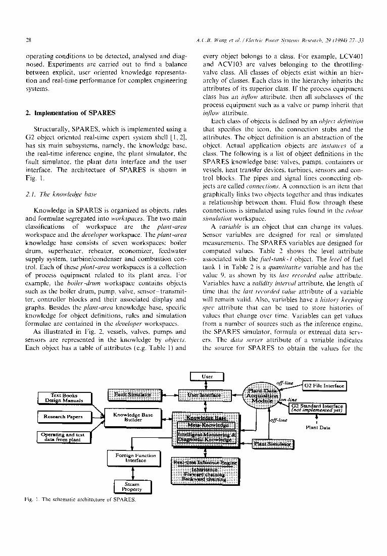
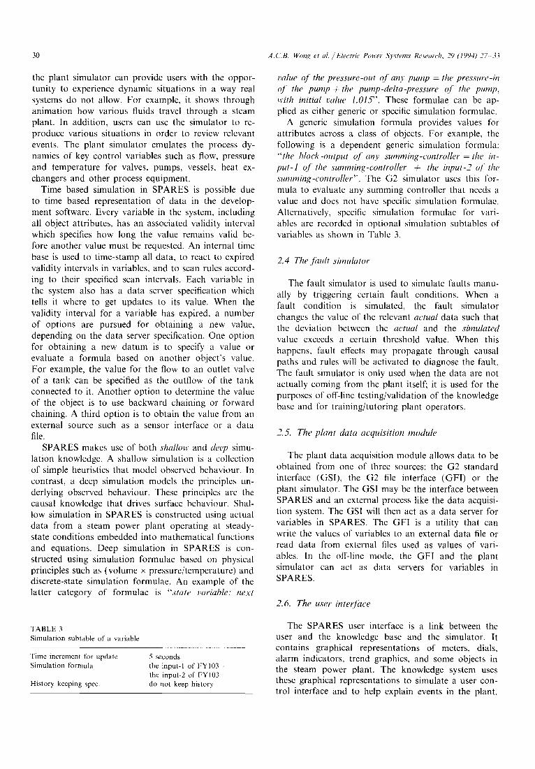
Structurally, SPARES, which is implemented using a G2 object oriented real-time expert system shell [1,2], has six main subsystems, namely, the knowledge base, the real-time inference engine, the plant simulator, the fault simulator, the plant data interface and the user interface. The architecture of SPARES is shown in Fig. 1.
2. 1. The knowledge base
Knowledge in SPARES is organized as objects, rules and formulae segregated into workspaces. The two main classifications of workspace are the plant-area workspace and the developer workspace. The plant-area knowledge base consists of seven workspaces: boiler drum, superheater, reheater, economizer, feedwater supply system, turbine/condenser and combustion con- trol. Each of these plant-area workspaces is a collection of process equipment related to its plant area. For example, the boiler-drum workspace contains objects such as the boiler drum, pump, valve, sensor-transmit- ter, controller blocks and their associated display and graphs. Besides the plant-area knowledge base, specific knowledge for object definitions, rules and simulation formulae are contained in the developer workspaces.
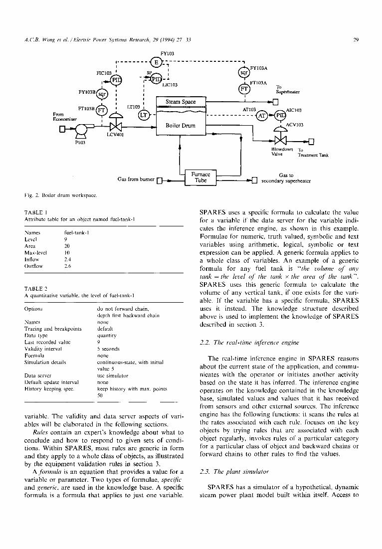
As illustrated in Fig. 2, vessels, valves, pumps and sensors are represented in the knowledge by objects. Each object has a table of attributes (e.g. Table 1) and
every object belongs to a class. For example, LCV401 and ACV103 are valves belonging to the throttling- valve class. All classes of objects exist within an hier- archy of classes. Each class in the hierarchy inherits the attributes of its superior class. If the process equipment class has an i;~/tow attribute, then all subclasses of the process equipment such as a valve or pump inherit that in[tow attribute.
Each class of objects is defined by an object d~'[inition that specifies the icon, the connection stubs and the attributes. The object definition is an abstraction of the object. Actual application objects are instances of a class. The following is a list of object definitions in the SPARES knowledge base: valves, pumps, containers or vessels, heat transfer devices, turbines, sensors and con- trol blocks. The pipes and signal lines connecting ob- jects are called connections. A connection is an item that graphically links two objects together and thus indicates a relationship between them. Fluid flow through these connections is simulated using rules found in the colour simulation workspace.
A variable is an object that can change its values. Sensor variables are designed for real or simulated measurements. The SPARES variables are designed for computed values. Table 2 shows the level attribute associated with the fuel-tank-1 object. The level of fuel tank 1 in Table 2 is a quantitative variable and has the value 9, as shown by its last recorded vahw attribute. Variables have a validio' interval attribute, the length of time that the last recorded value attribute of a variable will remain valid. Also, variables have a histo O, keeping spec attribute that can be used to store histories of values that change over time. Variables can get values from a number of sources such as the inference engine, the SPARES simulator, formula or external data serv- ers. The data server attribute of a variable indicates the source for SPARES to obtain the values for the
Text Books Design Manuals
Research Papers
Operating and test data from plant
User I
::::::::::::::::::::::::::::::::: ........................................... :(::| 13:!:3:3:3:3:3:3:3:1:!:!:3:3:1ii:3::!:4~:!:::::::i 3~ : ! : : ! : : :~:~ ~
Kn°~lu~ldg~rB as¢ L~iiiiiiii!iiiiii!iii ~ i:iiiiiiiiiiii!iiiii:i/
Foreign Function Interface
I Steam Property I
Fig. 1. The schematic architecture of SPARES.
..................... ..................................................................................
,...,......-.... -.-.-..- - - • ~ . . . ~ . . . . . . . . . . . . . . . . . . . . . . . .
Iii::::i:~i~i~ i~ ~iiiiii[::ii::::ii::::::l
~ ~ G2 File Interface [
G2 Standard Interface | I (nOt i~len,~ntedyet) ]
~ff-line Plant Data
.:.:.:.:,:.:.:.:.:,:.:,:.:?:,:.:.
A.C.B. Wong et al./Electric' Power Systems Research, 29 (1994) 27 33 29
FY103
i j @FYI03A - - _ &
12"-A~LIC103 FYI03B(~ ! @FTI03A To Superheater
- Boi ~ACV103
-1 :- I P103
Blowdown To Valve Treatment Tank
Furnace ] Gas to Gas from burner ~ ~ Tube ] ~ secondary superheater
Fig. 2. Boiler drum workspace.
TABLE 1 Attribute table for an object named fuel-tank-1
Names fuel-tank- l Level 9 Area 20 Max-level 10 Inflow 2.4 Outflow 2.6
TABLE 2 A quantitative variable, the level of fuel-tank-1
Options do not forward chain, depth first backward chain
Names none Tracing and breakpoints default Data type quantity Last recorded value 9 Validity interval 5 seconds Formula none Simulation d e t a i l s continuous-state, with initial
value 5 Data server use simulator Default update interval none History keeping spec. keep history with max. points
50
variable. The validity and data server aspects of vari- ables will be elaborated in the following sections.
Rules contain an expert 's knowledge about what to conclude and how to respond to given sets of condi- tions. Within SPARES, most rules are generic in form and they apply to a whole class of objects, as illustrated by the equipment validation rules in section 3.
A formula is an equation that provides a value for a variable or parameter. Two types of formulae, specific and generic, are used in the knowledge base. A specific formula is a formula that applies to just one variable.
SPARES uses a specific formula to calculate the value for a variable if the data server for the variable indi- cates the inference engine, as shown in this example. Formulae for numeric, truth valued, symbolic and text variables using arithmetic, logical, symbolic or text expression can be applied. A generic formula applies to a whole class of variables. An example of a generic formula for any fuel tank is "the volume o f any tank = the level o J" the tank x the area o f the tank". SPARES uses this generic formula to calculate the volume of any vertical tank, if one exists for the vari- able. If the variable has a specific formula, SPARES uses it instead. The knowledge structure described above is used to implement the knowledge of SPARES described in section 3.
2.2. The real-time inference engine
The real-time inference engine in SPARES reasons about the current state of the application, and commu- nicates with the operator or initiates another activity based on the state it has inferred. The inference engine operates on the knowledge contained in the knowledge base, simulated values and values that it has received from sensors and other external sources. The inference engine has the following functions: it scans the rules at the rates associated with each rule, focuses on the key objects by trying rules that are associated with each object regularly, invokes rules of a particular category for a particular class of object and backward chains or forward chains to other rules to find the values.
2.3. The plant simulator
SPARES has a simulator of a hypothetical, dynamic steam power plant model built within itself. Access to
30 A.CB. Wong et al./Electric Power Systems Research, 29 (1994) 27 33
the plant simulator can provide users with the oppor- tunity to experience dynamic situations in a way real systems do not allow. For example, it shows through animation how various fluids travel through a steam plant. In addition, users can use the simulator to re- produce various situations in order to review relevant events. The plant simulator emulates the process dy- namics of key control variables such as flow, pressure and temperature for valves, pumps, vessels, heat ex- changers and other process equipment.
Time based simulation in SPARES is possible due to time based representation of data in the develop- ment software. Every variable in the system, including all object attributes, has an associated validity interval which specifies how long the value remains valid be- fore another value must be requested. An internal time base is used to t ime-stamp all data, to react to expired validity intervals in variables, and to scan rules accord- ing to their specified scan intervals. Each variable in the system also has a data server specification which tells it where to get updates to its value. When the validity interval for a variable has expired, a number of options are pursued for obtaining a new value, depending on the data server specification. One option for obtaining a new datum is to specify a value or evaluate a formula based on another object's value. For example, the value for the flow to an outlet valve of a tank can be specified as the outflow of the tank connected to it. Another option to determine the value of the object is to use backward chaining or forward chaining. A third option is to obtain the value from an external source such as a sensor interface or a data file.
SPARES makes use of both shallow and deep simu- lation knowledge. A shallow simulation is a collection of simple heuristics that model observed behaviour. In contrast, a deep simulation models the principles un- derlying observed behaviour. These principles are the causal knowledge that drives surface behaviour. Shal- low simulation in SPARES is constructed using actual data from a steam power plant operating at steady- state conditions embedded into mathematical functions and equations. Deep simulation in SPARES is con- structed using simulation formulae based on physical principles such as (volume x pressure/temperature) and discrete-state simulation formulae. An example of the latter category of formulae is "state variable: next
TABLE 3 Simulation subtable of a variable
Time increment for update Simulation formula
History keeping spec.
5 seconds the input-I of FY103 + the input-2 of FYI03 do not keep history
value of the pressure-out of any pump = the pressure-in off the pump + the pump-delta-pressure of the pump, with initial value 1.015". These formulae can be ap- plied as either generic or specific simulation formulae.
A generic simulation formula provides values for attributes across a class of objects. For example, the following is a dependent generic simulation formula: "the bh)ck-output of any summing-controller = the in- put-1 of the summing-controller + the input-2 o/" the summing-controller". The G2 simulator uses this for- mula to evaluate any summing controller that needs a value and does not have specific simulation formulae. Alternatively, specific simulation formulae for vari- ables are recorded in optional simulation subtables of variables as shown in Table 3.
2.4 The .fault simulator
The fault simulator is used to simulate faults manu- ally by triggering certain fault conditions. When a fault condition is simulated, the fault simulator changes the value of the relevant actual data such that the deviation between the actual and the simulated value exceeds a certain threshold value. When this happens, fault effects may propagate through causal paths and rules will be activated to diagnose the fault. The fault simulator is only used when the data are not actually coming from the plant itself; it is used for the purposes of off-line testing/validation of the knowledge base and for training/tutoring plant operators.
2.5. The plant data acquisition module
The plant data acquisition module allows data to be obtained from one of three sources: the G2 standard interface (GSI), the G2 file interface (GFI) or the plant simulator. The GSI may be the interface between SPARES and an external process like the data acquisi- tion system. The GSI will then act as a data server for variables in SPARES. The G F I is a utility that can write the values of variables to an external data file or read data from external files used as values of vari- ables. In the off-line mode, the G F I and the plant simulator can act as data servers for variables in SPARES.
2.6. The user interface
The SPARES user interface is a link between the user and the knowledge base and the simulator. It contains graphical representations of meters, dials, alarm indicators, trend graphics, and some objects in the steam power plant. The knowledge system uses these graphical representations to simulate a user con- trol interface and to help explain events in the plant.
A.C.B. Wong et al./Electric Power Systems Research. 29 (1994) 27 33 31
3. Implementation of intelligent monitoring and diagnostic knowledge
3. I. Intelligent monitoring knowledge
Intelligent monitoring knowledge consists of two parts: process equipment validation and power plant efficiency computation. For example, the following equipment validation rules capture human expertise relating to observed behaviour of equipment failure. These heuristic rules represent temporal knowledge and are capable of expressing dynamic relationships. The following rule operates on the premise that in a control process a sensor operating normally will pick up noise generated by the process. This noise will cause fluctua- tions in the output of the sensor. A sensor that does not exhibit such a characteristic over a period of time can be concluded to be faulty.
for any sensor S if the rate of change per second of the block-output o f S during the last 10 seconds < the noise-level of S then inform the operator that "Suspect sensor [the name of S] is faulty"
The collections of plant data in the knowledge base are presented as low-level individual measurements. These individual measurements are upgraded to higher level information needed for plant diagnostic reasoning. Real-time power plant efficiency computation is an- other aspect of intelligent monitoring knowledge per- formed by SPARES to advise the plant operators on appropriate actions to be taken to improve thermal efficiency. The power plant efficiency computation knowledge consists of a boiler model and a turbine model. The boiler model calculates the thermal efficiency using both the input-output method and the heat loss method as stipulated by the ASME perfor- mance test code (PTC) 4.1 [3]. The efficiency of the turbine is measured in terms of the turbine heat rate. Both models are developed using the performance test data of a 250 MW generating unit in Singapore. A curve fitting technique is used to determine the curves that fit the test data. The foreign function interface in SPARES calls a foreign function written in C program- ming language to evaluate the thermodynamic proper- ties of water/steam such as specific volume, specific entropy and specific enthalpy.
3.2. Diagnostic knowledge
The approach that a human expert uses in a real- time situation is to maintain a peripheral awareness across the domain, watching for performance excep- tions, and then focusing on areas of interest. The SPARES inference engine operates similarly. The infer- ence engine continually scans knowledge which the
expert has specified for peripheral awareness. Meta- level diagnostic knowledge in the form of meta-rules controls the usage of relevant parts of the knowledge base to ensure efficient and effective diagnostic reason- ing. Since the SPARES diagnostic emphasis is to detect, analyse and diagnose faulty and inefficient operating conditions, top-level symptoms such as excessive smoke opacity and high exhaust gas temperature are selected for peripheral awareness. If high exhaust gas tempera- ture is detected at the stack over a long period of time, for example, the SPARES inference engine uses meta- knowledge to determine which knowledge to invoke, thus focusing on a specific area of interest. Diagnostic knowledge in the form of time-sensitive if-then, whichever and other rules enables the basic causes of detected problems to be determined.
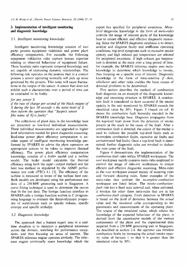
This section describes the method of combustion fault diagnosis on an example of the diagnostic knowl- edge and reasoning structure in SPARES. A combus- tion fault is considered to have occurred if the smoke opacity in the unit monitored by SPARES exceeds the simulated value by 30%. Figure 3 (based on ref. 4) shows the combustion fault hierarchy encoded in the SPARES knowledge base. Diagnosis propagates from the top-level fault down from the detection of smoke present at the stack to the cause of the fault. After a combustion fault is detected, the colour of the smoke is used to indicate the possible top-level faults such as incomplete combustion faults, excessive air faults and contaminated fuel faults. Once a top-level fault is deter- mined, further diagnostic rules are invoked to deduce the root cause of the fault.
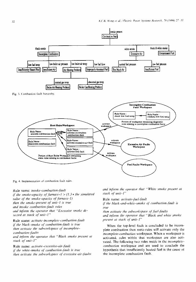
Figure 4 demonstrates the implementation of the combustion fault rules within SPARES workspaces. The root workspace mainly contains meta-rules employed to control the usage of relevant workspaces to ensure efficient and effective diagnostic reasoning. Meta-rules in the root workspace consist mainly of scanning rules and forward chaining rules. Some examples of the meta-rules that activate the incomplete-combustion workspace are listed below. The invoke-combustion- fault rule has a fixed scan interval and, when activated, it invokes the other three meta-rules that are in the combustion-Ji~ult category. Fault detection in SPARES is based on the level of deviation between the actual value and the simulated value corresponding to the parameters and measurements of the operating plant. The source of the simulated value, which relates the knowledge of the expected behaviour of the plant, is derived from the quantitative models of the various components of the plant and the experimental data acquired from a 250 MW generating unit in Singapore. As described in section 2.4, the operator can simulate combustion faults by increasing the actual smoke opac- ity value of furnace 1 so that it is greater than the simulated value by 30%.
32 A.C.B. Wong et al./Electric Power Systems Research, 29 (1994) 27 33
sm0ke-p~sent [Combustion F~I t
black-smoke [ [ lncomplez Co~umion I
I~.m=~y~<ll II~mm~,l IAirma~oblm[
I [n0m~g~+ la~0.n~'g~mp
I ~iler Air Heating Probtcm] I Boikt Gas Heatin~ Pr0blcml
I temp l iow f~i,ow 1
while.ma0ke I black & white sm0ke [
I Excessive Air ] [Concreted Furl ] I
[normal ~1 pmss~ flow fuel l~ssu~ I T°°m`h~ I I l~ammntF~l I
Fig. 3. Combustion fault hierarchy.
Incomplete Combustion Fault Workspace
/ I Rulc Name : ~ RuleNam¢ : ]
~-- .., ~ activate ~ nile.s relating to incomplete combustion faults / f Root .uies.orkspace ~ workspac* - "
/ I ,,~oN,~o: I m~oko~ g~.[-fd~,mo..-r-------~ X---"" / I ~uti'e~n:ornbustion-fault~ ictiv,a~-',mcoi~lp!c,c- ~ X
/ ' IX 'x . ~ \ _ . - - ,,
Ideactivam-eombustion-fault I ~ ~ ~ ' ~ L " t ~ c ¢ { Excessive Alr Faults "~ \ . Portion of Root RUltom Workspace cztaining ~ ~m°'~-~',., .+.,., , , ,~.~'~ ~ / ~ - . : 3 +'~o ~ _7 /
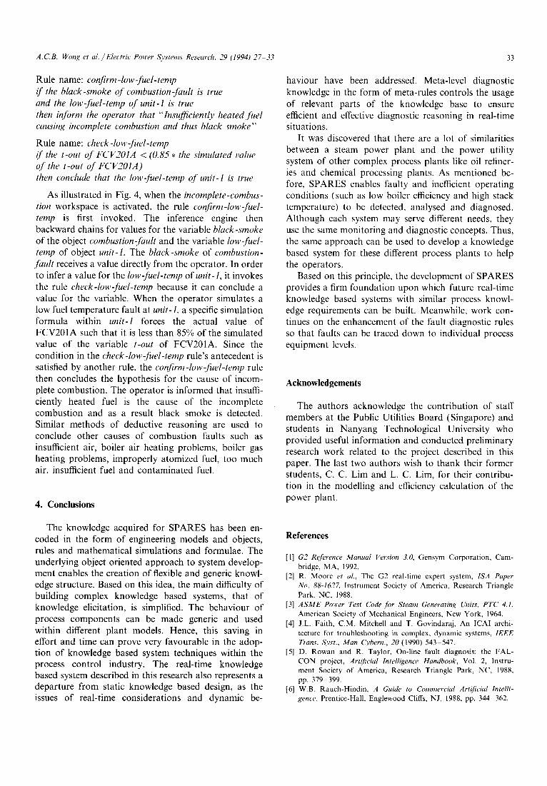
Fig. 4. Implementation of combustion fault rules.
Rule name: invoke-combustion-fault if the smoke-opacity of furnace- 1 > (1.3 * the simulated value of the smoke-opacity of furnace-l) then the smoke-present of unit-I is true and invoke combustion-fault rules and inform the operator that "Excessive smoke de- tected at stack of unit- 1"
Rule name: activate-incomplete-combustion-fault if the black-smoke of combustion-fault is true then activate the subworks'pace of incomplete- combustion -faults and inJorm the operator that "Black smoke present at stack of unit-l"
Rule name: activate-excessive-air-fault if the white-smoke of combustion-fault is true then activate the subworkspace of excessive-air-[~tults
and inform the operator that "White smoke present at stack of unit- 1""
Rule name: activate-fuel-Jault if the black-and-white-smoke of combustion-fault is true then activate the subworkspace of fuel-faults and inform the operator that "Black and white smoke present at stack of unit-l"
When the top-level fault is concluded to be incom- plete combustion then meta-rules will activate only the incomplete-combustion workspace. When a workspace is activated, rules within that workspace are also acti- vated. The following two rules reside in the incomplete- combustion workspace and are used to conclude the hypothesis that insufficiently heated fuel is the cause of the incomplete combustion fault.
A.C.B. Wong et al./Electric Power Systems Research, 29 (1994) 27 33 33
Rule name: confirm-low-fuel-temp if the black-smoke of combustion-fault is" true and the low-fuel-temp of unit-I is true then inform the operator that "Insufficiently heated fuel causing incomplete combustion and thus black smoke"
Rule name: check-low-fuel-temp if the t-out of FCV2OIA < (0.85* the simulated value of the t-out of FCV2OIA) then conclude that the low-fuel-temp of unit-1 is true
As illustrated in Fig. 4, when the incomplete-combus- tion workspace is activated, the rule confirm-low-fuel- temp is first invoked. The inference engine then backward chains for values for the variable black-smoke of the object combustion-fault and the variable low-fuel- temp of object unit-1. The black-smoke of combustion- fault receives a value directly from the operator. In order to infer a value for the low-Ji~el-temp of unit-1, it invokes the rule check-low-fuel-temp because it can conclude a value for the variable. When the operator simulates a low fuel temperature fault at unit-1, a specific simulation formula within unit-1 forces the actual value of FCV201A such that it is less than 85% of the simulated value of the variable t-out of FCV201A. Since the condition in the check-low-fuel-temp rule's antecedent is satisfied by another rule, the confirm-low-fuel-temp rule then concludes the hypothesis for the cause of incom- plete combustion. The operator is informed that insuffi- ciently heated fuel is the cause of the incomplete combustion and as a result black smoke is detected. Similar methods of deductive reasoning are used to conclude other causes of combustion faults such as insufficient air, boiler air heating problems, boiler gas heating problems, improperly atomized fuel, too much air, insufficient fuel and contaminated fuel.
4. Conclusions
haviour have been addressed. Meta-level diagnostic knowledge in the form of meta-rules controls the usage of relevant parts of the knowledge base to ensure efficient and effective diagnostic reasoning in real-time situations.
It was discovered that there are a lot of similarities between a steam power plant and the power utility system of other complex process plants like oil refiner- ies and chemical processing plants. As mentioned be- fore, SPARES enables faulty and inefficient operating conditions (such as low boiler efficiency and high stack temperature) to be detected, analysed and diagnosed. Although each system may serve different needs, they use the same monitoring and diagnostic concepts. Thus, the same approach can be used to develop a knowledge based system for these different process plants to help the operators.
Based on this principle, the development of SPARES provides a firm foundation upon which future real-time knowledge based systems with similar process knowl- edge requirements can be built. Meanwhile, work con- tinues on the enhancement of the fault diagnostic rules so that faults can be traced down to individual process equipment levels.
Acknowledgements
The authors acknowledge the contribution of staff members at the Public Utilities Board (Singapore) and students in Nanyang Technological University who provided useful information and conducted preliminary research work related to the project described in this paper. The last two authors wish to thank their former students, C. C. Lim and L. C. Lim, for their contribu- tion in the modelling and efficiency calculation of the power plant.
The knowledge acquired for SPARES has been en- coded in the form of engineering models and objects, rules and mathematical simulations and formulae. The underlying object oriented approach to system develop- ment enables the creation of flexible and generic knowl- edge structure. Based on this idea, the main difficulty of building complex knowledge based systems, that of knowledge elicitation, is simplified. The behaviour of process components can be made generic and used within different plant models. Hence, this saving in effort and time can prove very favourable in the adop- tion of knowledge based system techniques within the process control industry. The real-time knowledge based system described in this research also represents a departure from static knowledge based design, as the issues of real-time considerations and dynamic be-
References
[1] G2 Reference Manual Version 3.0, Gensym Corporation, Cam- bridge, MA, 1992.
[2] R. Moore et al., The G2 real-time expert system, ISA Paper No. 88-1627, Instrument Society of America, Research Triangle Park, NC, 1988.
[3] A S M E Power Test Code for Steam Generating Units, PTC 4.1, American Society of Mechanical Engineers, New York, 1964.
[4] J.L. Faith, C.M. Mitchell and T. Govindaraj, An ICAI archi- tecture for troubleshooting in complex, dynamic systems, 1EEE Trans. Syst., Man Cybern., 20 (1990) 543 547.
[5] D. Rowan and R. Taylor, On-line fault diagnosis: the FAL- CON project, Artificial Intelligence Handbook, Vol. 2, Instru- ment Society of America, Research Triangle Park, NC, 1988, pp. 379-399.
[6] W.B. Rauch-Hindin, A Guide to Commercial Artificial Intelli- gence, Prentice-Hall, Englewood Cliffs, NJ, 1988, pp. 344 362.
Recommended