L
...... GEI-31208A
INSTRUCTIONS
CR7931-NA108
VOLTAGE REGULATOREQUIPMENT
-, m mil wm m , .
GENERAL_ ELECTRIC,
CONTENTS
Page
INTRODUCTION....................................... 3
RECEIVING, HANDLING AND STORAGE ...................... 3
Receiving and Handling 3Storage ........................... . ...... _..' ._ . . . . 3
DESCRIPTION ........................................ 3
Component Arrangement ............................... 3Voltage Regulator .................................... 4Stabilizing Transformers ............................... 8Underexcited Reactive-Ampere Limit ....................... 8Exciter Polarizing ................................... 10Auxiliary Equipment .................................. 10
INSTALLATION .......................... , ............ 16
Location and Mounting ................................. 16Con_nections ........................................ 16
Polarity and Phase Rotation ............................. 16
INITIAL OPERATION, TESTING AND ADJUSTMENT .............. 17
Control Circuits ..................................... 17
Regulator ......................................... 17Underexcited Reactive-Ampere Limit ...................... 21Equalizing Reactor and Line-drop Compensator ................ 25
OPERATION .......................................... 25
Normal Operation .................................... 25Exciter Polarity Reversal .............................. 26
MAINTENANCE....................................... 27
Static Equipment .................................... 27Other Equipment .................................... 27
TROUBLE SHOOTING ................................... 27
General .......................................... 27
TROUBLE-SHOOTING CHART ............................. 27
RENEWALPARdiS ..................................... 28
These mstruchom do not purport to cover all details or vorlahons m equipment nor to provide far every possible
contingency to be met in connechon with installation, operation or mamtenonce. Should further information be desiredor should portlcular probtems arise which are not covered _fflclently for the porchaser's purposes, the matter shouldbe referred to the Generol Electric Company
CR7931-NA108
VOLTAGE REGULATOR EQUIPMENT
INTRODUCTION
The CR7931-NA108 voltage-regulator equipment division of reactive current and to restrict the flowis designed to regulate automatically the terminal of cross currents between paralleled machines_ Avoltage of alternating-current generators and syn- line-drop compensator is occasionally provided tochro_ious condensers° The regulator supplies ex- facilitate the regulation of voltage at some point re-citation to an amplidyne generator which controls mote from the machine terminals. A motor starter
' the voltage of the a-e machine, for the amplidyne-driving motor, a magnetic switchfor placing the amplidyne inthe exciter-field circuit,
The regulator is normally equipped with anunder- an amplidyne voltmeter, and the necessary controlexcited reactive-ampere-limit unit. This unit pre- switches, relays, and control transformers are gen-vents the underexcited reactive current of the a-c erally included with the regulating equipment°
machine from being automatically increased materi- Both the number and the arrangement of the aux-ally above a desired minimum value which can be iliary components vary with the requirements of theeither dependent on, or independent of, the load on particular application. Therefore it is necessary tothe a-c machine, refer to the material lists and diagrams provided
A maximum excitation limit unit may be provided for each individual application to determine whatto reduce the excitation of the a-c machine in the material is included and what connections should be
event of excessive a-c machine field or armature used_ The diagrams shownin this book are for illus-currents, or field or stator temperatures. An equal- trative purposes only; they are not intended to applyizing reactor is usually included to permit proper to all installations.
RECEIVING, HANDLING AND STORAGE
RECEIVING AND HANDLING with the transportation company and the nearestGeneral Electric Sales Office should be notified
Immediately upon receipt, the equipment should promptly°
be carefullyunpacked to avoid damaging the appara- STORAGEtUSo Particular care should be exercised to preventsmall parts being mislaid or thrown away in the If the equipment is not' to be used as soon as it ispacking material, unpacked, it should be stored in a clean, dry place
As soon as the equipment is unpacked, it should and protected from accidental damage. Particularbe examined for any damage that might have been care should be exercised to avoid storing the equip-sustained in transit. If injury or rough handling is ment in locations where construction work is inevident, a damage claim should be filed immediately progress.
DESCRIPTION
COMPONENT ARRANGEMENT 1. A CR7932-CA control panel, which may con-tain atransfer contactor, a motor starter, and other
The CR7931-NA108 central station regulator is relaying devices.generally housed in a separate floor-mounted en-closure that can be opened at both the front and the 2. A CR7932-MA stabilizing panel, which con-back. It usually includes the following units: talus the adjustable resistors used for adjusting the
3
CR7931-NA108 Voltage Regulator GEI-31208A
gain of the regulator-stabilizing circuits and a ter- When the machine voltage is higher than normal,minal board for the customer's control connections, the regulator will supply control-field current to the
3. A stabilizing channel, which contains four amplidyne, so that the amplidynevoltagewilloppose,or "buck," the exciter voltage impressed act oss the
stabilizing transformers, exciter-field circuit. This will tend to reduce the4. A CR7930=NA regulator panel, which contains exciter-field current, lower the exciter voltage, and
the components of the comparison circuit and the decrease the field current and terminal voltage ofmagnetic amplifiers, the a-c machine toward normal.
5. A CR7932-KA underexcited reactive-ampere- When the machine terminal voltage isbelow nor-limit panel, mal, the regulator will supply control=field current
to the amplidyne which will produce an amplidyneWhen the equipment is supplied in a separate en- voltage in the opposite direction to raise, or _'boo-t__"
closure, a hinged framework at thefront of the case the exciter voltage impressed across the exciter-is used to carry the CR7930=NA regulator panel, field circuit. This will.[increase the exciterLfielcithe CR7932-KA underexcited reactive- ampere-limit current and the exciter voltage to raise the terminalpanel and any auxiliary panels which may be used.The CR7932-CA control panel and the CR7932-MA voltage of the 'a=c machine toward normal.stabilizing panel are supported on a stationary frame-work at the rear of the case. The stabilizing chan- The regulator and amplidyne can control auto-nel is mounted between the front and rear frame- matica2Jy the excitation and terminal voltage over
the complete load range of the machine, at any loadworks at the bottom of the case.from no load to rated load.
Ail panels have steel bases_ except the control The regulator-control switch is provided with apanel which has abase made of a compoundmaterial, position to be used for test and adjustment of theAil panels are provided with mounting holes so that regulator preparatory to placing it in service. Withthey may be bolted to supporting framework, the control switch at TEST, the regulator is con-
nected to the generator potential transformers andThe adjustments of the regulator panel and the while the amplidyne is operated, it is disconnected
underexcited reactive-ampere-limit panel, together from the exciter-field circuit so that it cannot affectwith the adjustments which may be incorporated in the excitation of the a-c machine. This permits allthe auxiliary panels, are made accessible by opening the regulator equipment to be operated for test pur-the front doors of the enclosing case. If it is neces- poses.sary to adjust any of the components mounted on therear of these panels, the framework mounting the REGULATOR SIGNAL VOLTAGE
regulator and the limit panel may be swung open. When the control switch is at ON, the regulatorThe stabilizing-circuit adjustments, the outgoing is connected to the secondaries of potential trans-
connections, the transfer contactor, the undervoltage formers, whose primaries are connected to the a-crelay, the motor starter and overload relays, a-c machine terminals or bus. If an equalizing reactorand d-c control-power switches, and fuses are ac- is not used, the potential transformers supply thecessible after the back doors of the enclosing case regulator with athree-phase signal voltage which ishave been opened, directly proportional to the machine terminal voltage.
In instances where the a-c machine wfil operateVOLTAGE REGULATOR in parallel with other machines, an equalizing re-
actor is connected in one of the transformer second-
GENERAL ary lines to the regulator. The effect of the equaliz-ing reactor upon the signal voltage is described in
As shown in Fig. 1G, the regulator can be placed the section on "Auxiliary Equipment."in or removed from service by operating the voltage-
regulator control switch. With this switch at OFF, REGULATOR CIRCUITthe excitation and terminal voltage of the a-c ma=chine can be manually controlled by _djusting the The three-phase signal voltage from the second-exciter-field rheostat; under this condition_ the regu- aries of the a-c machine potential transformers islator is completely out of service and the amplidyne impressed upon the major components of the regu-is removed from the exciter-field circuit. With the lator. These components may be divided into threecontrol switch at ON, the amplidyne is connected in groups: the comparison circuit, the magnetic am-series with the exciter field, and the regulator will plifier, and the amplidyne. The comparison circuitcontrol automatically the excitation and terminal may be further subdivided into the averaging and thevoltage of the a-c machine, reference circuits.
4
CR7931-NA108 Voltage Regulator GEI-31208A
3-phasevoltagefrom A-c ResEstormachine Autotronsformers , $
-/ __. __[_l[____lectif ier !__1 output 2
t ia from '/*" reference
. Rheost
-1A-c voltage Input
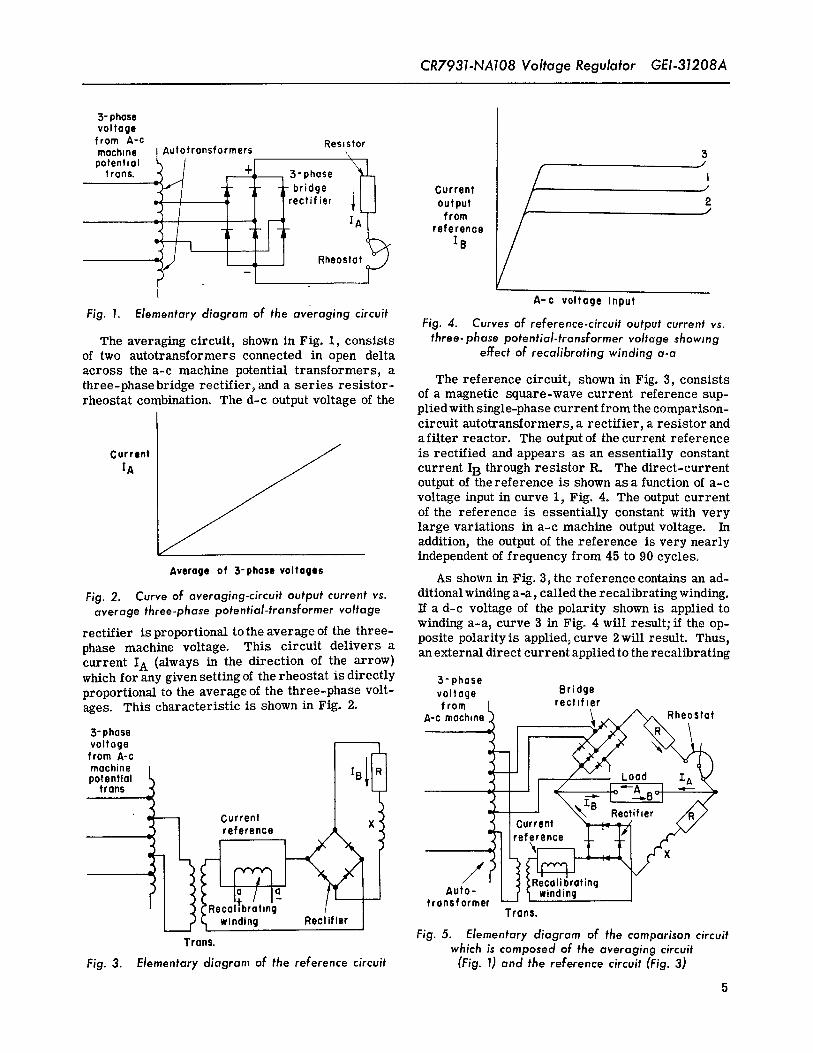
Fig. 1. Elementary diagram of the averaging circuitFig. 4. Curvesof reference-circuit output current vs.
The averaging circuit, shown in Fig. 1, consists three-phase potential-transformer voltage showingof two autotransformers connected in open delta effect of recalibrating winding a-aacross the a-c machine potential transformers, athree-phasebridge rectifier, and a series resistor- The reference circuit, shown in Fig. 3, consists
of a magnetic square-wave current reference sup-rheostat combination. The d-c output voltage of theplied with single-phase current from the comparison-circuit autotransformers, a rectifier, a resistor anda filter reactor. The output of the current reference
Current _ is rectified and appears as an essentially constant
IA _ current IB through resistor R. The direct-current
output of the reference is shown as a function of a-cvoltage input in curve 1, Fig. 4. The output currentof the reference is essentially constant with verylarge variations in a-c machine output voltage. Inaddition, the output of the reference is very nearlyindependent of frequency from 45 to 90 cycles.
Average of S-phasevoltagesAs shown in ,Fig. 3_the reference contains an ad-
Fig. 2. Curve of averaging-circuit output current vs. ditionalwindinga-a,calledtherecalibratingwinding.average three-phase potential-transformer voltage If a d-c voltage of the polarity shown is applied to
winding a-a, curve 3 in Fig. 4 will result, if the ap-rectifier is proportional to the average of the three- posite polarity is applied, curve 2 will result. Thus,phase machine voltage. This circuit delivers acurrent IA (always in the direction of the arrow) an externaldirect current appliedtotherecalibratingwhich for any given setting of the rheostat is directly 3- phaseproportional to the average of the three- phase volt- val tage Br idgeages. This characteristic is shown in Fig. 2, from rectdler
A-Croach,ne _ad__l L°_
S-phase
from A-cmachinepotential
frans I _/ _ !o;-A _! _--__/! -_ /-_- I --R I A/-
. __ / _,_B Rectif,er /'dR/_
= [_/urrent _ gurrent _r_.___
reference I Ireference _L _El ,.C"
Ig / I Auto-(_Recalabratmg fransformerLI winding Rectifier Trans.
Trans. Fig. 5. Elementary diagram of the comparison circuitwhich is composed of the averaging circuit
Fig. 3. Elementary diagram of the reference circuit (Fig. 1) and the reference circuit (Fig. 3)
5
CR7931-NA108 Voltage Regulator GE,'-31208A
Direct- current
/ _re;ion outputthroughloadLoad 0 .....
current _ Boost / ....
output current
/_ Normaloperating 4._
I range
Input voltage fram A-c machine:- 0 +
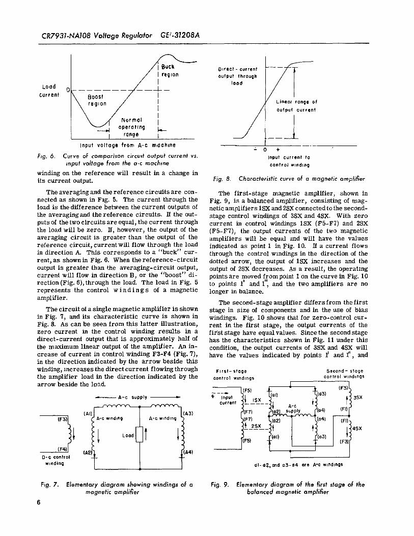
Fig. 6. Curve of comparison circuit output current vs. Input current loinput voltage from the a-c machine control winding
winding on the reference will result in a change inits current output. Fig. 8. Characteristic curve of a magnetic amplifier
The averaging and the reference circuits are con- The first-stage magnetic amplifier, shown innected as shown in Fzg. 5. The current through the Fig. 9, is a balanced amplifier, consisting of mag-load is the difference between the current outputs of neticamplifierslSXand2SX connected to the second-
the averaging and the reference circuits. If the out- stage control windings of 3SX and 4SX. With zeroputs of the two circuits are equal, the current through current in control windings 1SX (F5-F7) and 2SXthe load will be zero. If, however, the output of the (F5-F7)_ the output currents of the two magneticaveraging circuit is greater than the output of the amplifiers will be equal and will have the valuesreference circuit, current will flow through the load indicated as point 1 in Fig. 10. If a current flowsin direction A. This corresponds to a "buck" cur- through the control windings in the direction of the
rent, as shownin Fig. 6. When the reference-circuit dotted arrow, the output of 1SX increases and theoutput is greater than the averaging-circuit output, output of 2SX decreases. As a result, the operatingcurrent will flow in direction B_ or the "boost" di- points are moved from point 1 on the curve in Fig. 10
Il
rection (Fig. 6),through the load. The load in Fig. 5 to points 1' and 1, and the two amplifiers are norepresents the control windings of a magnetic longer in balance.
amplifier. The second-stage amplifier differs from the firstThe circuit of a single magnetic amplifier is shown stage in size of components and in the use of bias
in Fig. 7, and its characteristic curve is shown in windings. Fig. 10 shows that for zero-control cur-Fig. 8. As can be seen from this latter illustration, rent in the first stage, the output currents of thezero current in the control winding results in a firlst stage have equalvalues. Sincethe second stagedirect-current output that is approximately half of has the characteristics shown in Fig° 11 under this
the maximum linear output of the amplifier. An in- condition, the output currents of 3SX and 4SX willcrease of current in control winding F3-F4 (Fig. 7), have the values indicated by points iD and f', andin the direction indicated by the arrow beside this
winding, increases the direct current flowing through F,rst- stage Second- stagethe amplifier load in the direction indicated by the control windings control windings
,_ (F3)tarrow beside the lo_d. _ __._. ?5) loll -_ O3}
A-c supp,y _ + ,npu, I ,sx f!3sx
_ current ;.... _ A'C _;{Al) (A3) _(F7) (O2)ry._pply_.r._,_ 04) (FI)
f l__2sx_:+ 4sx
- I (F$). (F4)l (A2)l A4)
D-¢ control
winding ol-o2, and o3-a4 ore A-c windings
Fig. 7. Elementary diagram showing windings of a Fig. 9. Elementary diagram of the first stage of themagnetic amplifier balanced magnetic amplifier
6
GEI-31208A CR7931-NA108 Voltage Regulator
0 u t put to F4 is greater than the current flowing from F2 tocurrent Fl, the amplidyne voltage at terminal A1 will be
2SX .... {{ /'l_lSX negative, and will boost the exciter voltage to in-
crease the exciter-field current, thereby increasing
the a-c machine terminal voltage.
_= REGULATOR AND UNDEREXCITED REACTIVE-
AMPERE-LIMIT BURDEN
The regulator alone imposes an unbalanced three-phase burden at about 115 volts a-c on the a-c ma-chine potential transformers. The regulator willrequire a current of approximately 0.30 ampere inline 105, 2.3 amperes in line 107 and, 2.2 amperesin line 109. (Refer to Fig. 16). The regulator and- 0 +the underexcited reactive-ampere-limit, when both
Input current are used, will require a current of 0.4 ampere inline 105 and 2.3 amperes in lines 107 and 109.
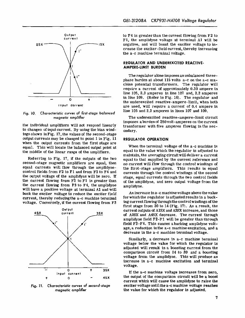
Fig. 10. Characteristic curves of first-stage balancedmagnetic amplifier The underexcited reactive-ampere-limit circuit
imposes a burden of 250 volt-amperes on the currentthe individual amplifiers will not respond linearly transformer with five amperes flowing in the sec-to changes of input current. By using the bias wind- ondary.ings shown inFig. 17, the values of the second-stageoutput currents may be changed to point 1 in Fig. 11 REGULATOR OPERATIONwhen the output currents from the first stage areequal. This will locate the balanced output point at When the terminal voltage of the a-c machine isthe middle of the linear range of the amplifiers, equal to the value which the regulator is adjusted to
maintain, the averaging circuitwill deliver a currentReferring to Fig. 17, if the outputs of the two equal to that supplied by the current reference and
second-stage magnetic amplifiers are equal, then no current will flow through the control windings ofequal currents will flow through the ampltdyne- the first-stage amplifiers. This results in equalcontrol fields from F2 to FI and from F3 to F4 and currents through the control windings of the secondthe output voltage of the amplidyne will be zero. If stage, equal currents through the two control fieldsthe current flowing from F2 to F1 is greater than of the amplidyne, and zero output voltage from thethe current flowing from F3 to F4, the amplidyne amplidyne.will have a positive voltage at terminal A1 and willbuck the exciter voltage to reduce the exciter field An increase in a-c machine voltage above the valuecurrent, thereby reducing the a-c machine terminal forwhichthe regulator is adjusted results in a buck-
voltage. Conversely, if the current flowing from F3 lng currentflowingthroughthe controlwindings ofthefirst stage from 20 to 14 (Fig. 17_. As a result, the
Output current outputs of A1SX and A3SX increase, and those45X current 39X of A2SX and A4SX decrease. The current through
amplidyne field F2-F 1 will be greater than throughfield F3-F4. This causes a bucking amplidyne volt-age, a reduction inthe a-c machine excitation, and adecrease in the a-c machine terminal voltage.
Similarly, a decrease in a-c machine terminalvoltage below the value for which the regulator isadjusted will result in a boosting current from thecomparison circuit from 14 to 20 and a boostingvoltage from the amplidyne. This will produce anincrease in a-c machine excitation and terminal
voltage.-- 0 '1' 39X
Input current If the a-c machine voltage increases from zero,_- o - 4sx the output of the comparison circuit will be a boost
current which will cause the amplidyne to raise the
Fig. 11. Characteristic curves of second-stage exciter voltage untilthe a-c machine voltage reachesmagnetic amplifier the value for which the regulator is adjusted.
?
CR7931-NA108 Voltage Regulator GEI.31208A
REGULATOR ADJUSTMENTS A3SX will tend to decrease and the output of A4SXwill tend to increase. This will result in a tendency
The nominal a-c machine terminal-voltage level to reduce the buck voltage or increase the boostfor which the regulator is adjusted is determined by voltage from the amplidyne.the connections of the autotransformer taps. Normaladjustment of voltage is obtained by setting the A resistor-rheostat combination is usually con-voltage-adjusting rheostat_ nected in series with the stabilizer primaries to
permit adjustment of the primary-circuit resistanceRegulator sensitivity may be varied by means of (Fig. 16). Stabilizer adjustments are made in thethe rheost/tt in series with the output of the compari-
son circuits. This rheostat is called the SENSITIV- factory although in individual applications specialadjustments may be made to obtain optimum per-
1TY rheostat. Increasing the resistance decreases formance.sensitivity, while d e c r e a s i n g the resistance in_
creases the sensitivity. UNDEREXCITED REACTIVE-AMPERE LIMITThe BALANCE adjustment provides a means of
compensating for slight differences in output of the The function of the underexcited reactive-ampere-seconcl-stage magnetic amplifiers with zero input limit circuit, shown in Fig. 18, is to prevent thecontrol current to the first-stage magnetic ampli- regulator from reducing the a-c machine excitationfiers to such a iow valuethat the machinewouldfall out
Second-stage bias and amplidyne negative feedback of synchronism. It operates by limiting the machineif used are adjusted at the factory and do not usually underexcited reactive current.require further adjustment. Voltage level, sensitivity,
Under normal operating conditions, with the regu-and balance are also adjusted at the factory, butfurther adjustment may be required at the time of lator and the limit in service, the underexcitedreac-installation, tive current of the a-c machine is less thanthe value
at which the limit functions, and the limit is inopera-STABILIZING TRANSFORMERS tive. However, if the regulator reducesthe machine
excitation to a sufficiently low value, the limit tm-To prevent excessive overshooting of the a-c mediatelybecomes operative and prevents the under-
machine voltage and to obtain voltage stability, stabi- excited reactive current from rising materiallylizing transformers are generally used, as shown above the value for which the limit is adjusted. Thein Fig. 16 and 17. The primary of the exciter sta- direct-current output from the limit circuit is am-bilizing transformer is connected to the exciter plified and applied to the recalibrating winding ofarmature (Fig. 16). The secondary of this stabilizer the current reference to increase the current outputis connected in series with a reactor and with the of the reference. As a result, the voltage regulatortwo stabilizing windings of the first-stage magnetic is recalibrated to hold a higher machine voltage.amplifier (Fig. 17). The stabilizers will supply cur- Consequently, the limit will prevent appreciable in-rent to the amplifier stabilizing windings only when creases in machine underexcited reactive currentthe exciter voltage is changing and, therefore, are beyond a predetermined value by increasing the volt-effective only during transient conditions. T-hey are age for which the regulator is adjusted, and usuallyineffective when the exciter voltage is not changing, will increase the machine terminal voltage held byand stabilizer action _s not required, the regulator.
Neglecting voltage drops due to winding resist- Since in many cases the magnitude of the under-ance, with the exciter voltage increasing, point 31 excited reactive current at which the a-c machineon 1ST-S, Flgo 17, will become positive. This will would fallout of synchronism is a function of machinetend to increase the output of A1SX _nd therefore active current, the limit can be adjusted so that theA3SX and to decrease the output of A2SX and. A4SX. value of underexcited reactive current at which theThis effect will tend to change the amplidyne voltage limit will become operative (the limit-start point)in the bucl- direction, and will oppose anincrease in will decrease as the machine active current in-exciter voltage to prevent overshooting and insta- creases. Therefore, it is possible to arrange thebihty. With the exciter voltage falling, the opposite limit so that its starting point is automaticallyaction will take place to oppose the decrease in ex- "' changed as machine active current varies. Activeciter voltage, current is the in-phase or watt component of the
machine armature current.A similar stabilizing transformer is connected
across the amplidyne. The secondary is connected A single-phaseline to line voltage of the a-c ma-in series with the magnetic amplifier stabilizing chine is applied through a potential transformer towindings of the second stage. If the amplldyne volt- the primary of transformer B3T (Fig. 18). A cur-age increases in the buck direction, the output of rent signal, obtained from the secondary of a current
8
GEI-31208A CR7931-NA108 Voltage Regulator
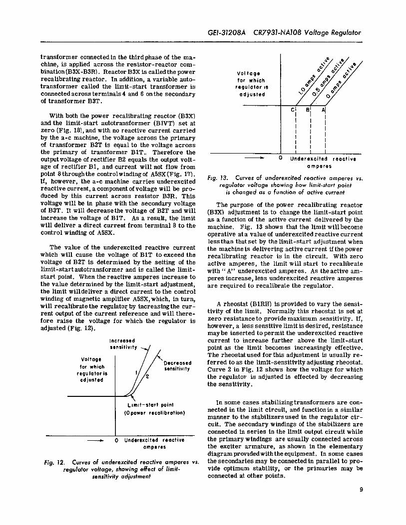
transformer connected in the third phase of the ma- _./ ../chine, ts applied across the resistor-reactor cam- ex'/ _'/ _bination(B3X-B3R). Reactor B3X is calledthe power Vol taqe d'/ oo/ (_-/recalibrating reactor. In addition, a variable auto- tar which _-/ _-/_/_"/A_''_/- _/transformer called the limit-start transformer is regulator ,s o/ _o/ ._"/o_//_,°_/ -_q/connected across terminals 4 and 6 on the secondary a d j uate d "'_of transformer B3T. __J__/__/
c, "l AlWith both the power recalibrating reactor (B3X) Iand the limit-start autotransformer (B1VT) set at Izero (Fig. 18), and with no reactive current carried I}by the a-c machine, the voltage across the primary Iof transformer B2T is equal to the voltage across Ithe primary of transformer BlT. Therefore the }output voltage of rectifier B2 equals the output volt- ,_ O Underexcited reactiveage of rectifier BI, and current will not flow from amperes
point 8throughthe controlwindingof ASSX(Fig. 17). Fig. 13. Curves of underexcited reactive amperes vs.If, however, the a-c machine carries underexcited regulator voltage showing how limit-start pointreactive current, a component of voltage will be pro- is changed as a function of active currentduced by this current across resistor B3R. This
voltage will be in phase with the secondary voltage The purpose of the power recalibrating reactorof B3T. It will decreasethe voltage of B2T and will (B3X) adjustment is to change the limit-start pointincrease the voltage of BlT. As a result, the limit as a function of the active current delivered by thewill deliver a direct current from terminal 8 to the machine. Fig. 13 shows that the limit willbecomecontrol winding of A5SX. operative at a value of underexcited reactive current
less than that set by the limit-start adjustment whenThe value of the underexcited reactive current the machineis delivering active current ifthepower
which will cause the voltage of BlT to exceed the recalibrating reactor ts in the circuit. With zerovoltage of B2T is determined by the setting of the active amperes, the limit will start to recalibratelimit-startautotransformer and is called the limit- with"A' underexcited amperes. As theactive am-start point. When the reactive amperes increase to peres increase, less underexcited reactive amperesthe value determined by the limit-start adjustment, are required to recalibrate the regulator.the limit willdeliver a direct current to the control
winding of magnetic amplifier A5SX, which, in turn,A rheostat (B1RH) is provided to vary the senst-will recalibratethe regulator by increasingthe cur-
rent output of the current reference and will there- tivity of the limit. Normally this rheostat is set atfore raise the voltage for which the regulator is zero resistance to provide maximum sensitivity. If,adjusted (Fig. 12). however, a less sensitive limit is desired, resistance
maybe inserted to permit the underexcited reactiveIncreased current to increase further above the limit-startsensitiv,ty -..../ point as the limit becomes increasingly effective.
'{__ The rheostat used for this adjustment is usually re-
Voltage Decreased ferred to as the limit-sensitivity adjusting rheostat.tar which sensitivity Curve 2 in Fig. 12 shows how the voltage for whichregulator isadjusted the regulator is adjusted is effected by decreasing
the sensitivity.
L,m,t-start point In some cases stabilizingtransformers are con-nected in the limit circuit, and function in a similar{0 power recelibration)manner to the stabilizers used in the regulator cir-cuit. The secondary windings of the stabilizers areconnected in series in the limit output circuit while
0 Underexcited reactive the primary windings are usually connected acrossamperes the exciter armature, as shown in the elementary
diagram provldedwith the equipment. In some cases
Fig. 12. Curves of underexcited reactive amperes vs. the secondaries may be connected in parallel to pro-regulator voltage, showing effect of limit- vide optimum stability, or the primaries may be
sensitivityadjustment connected at other points.
9
GEI-31208A CR7931-NA108Voltage Regulator
EXCITER POLARIZING f_
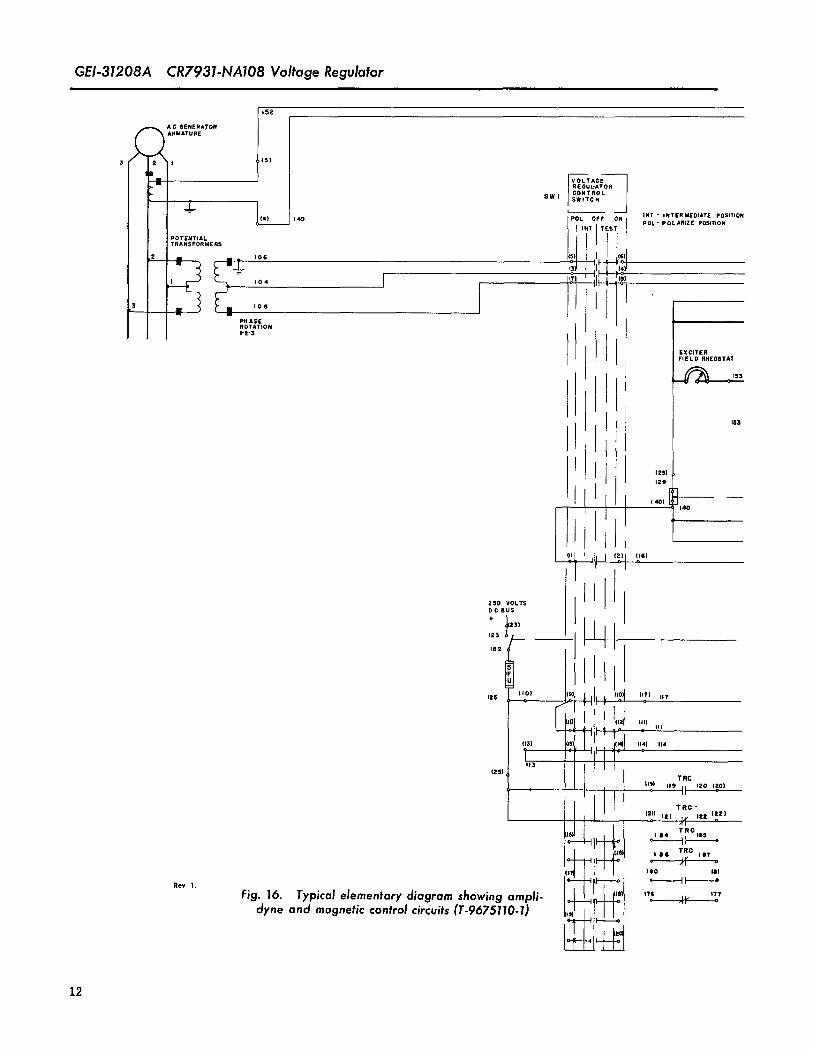
An exciter polarizing circuit is sometimes pro- _./- A-cmochine
vided. If the polarity of the exciter is wrong, it may _ Potentialtransformersbe reversed by means of the circuit consisting of
rectifiers 1REC,2REC2,and 2REC1, resistor2R, __ Ii Iand amplidyne field F9-F10 (Fig. 16). With the con- itrol switch at POLARIZE, rectifiers 1REC, 2REC1, _- ReQulotor
- input auto-[
tr°?2f°rm'Jand 2REC2 will allow current to flow from the ex- Equohzmgreactorciter, through the rectifiers, through resistor 2R, r#,_e-t_s .... _,
and through the amplidyne field from F9 to Fl0, if ,r--,_l_ _P '_'the exciter has the opposite polarity from that shown ,x[ __{in Fig°16. This current flow is aided by the voltage , 'from transformer secondary 3TS1, rectified by
1REC. As a result amplidyne terminal C2 will be- cz[ 'i[ o-1 _'
field in a directiontocause the exciter voltage to bereduced to zero. Transformer 3T will maintain the I {.__Co2jse_taPs ___j _ _: ,Averaging
voltage on the amplidynein the same direction until To load [ _ -_ [ ctrcu,tw]
the exciter voltage hasbeen reversed and increased . ] _ -_ [in the correct direction. Whenthe exciter voltage -'
balances the voltage from 1REC, the current through _field F9-F10 becomes zero. This will occur at a Tocurrentlow value of exciter voltage. The exciter will then reference
be correctly polarized.This circuit may also be used when the exciter Fig. 14. Equalizing-reactor connections
residual-field flux is not sufficient to permit the ex-citer armature voltage to build up when starting the overexcited reactive current if the machine is op-exciter as aself-excitedmachine. In special cases, crating in parallel with another machine.other circuits may be used for exciter polarizing.
If the a-c machine is operating inthe underexcitedAUXILIARY EQUIPMENT region, the equalizing reactor will decrease the
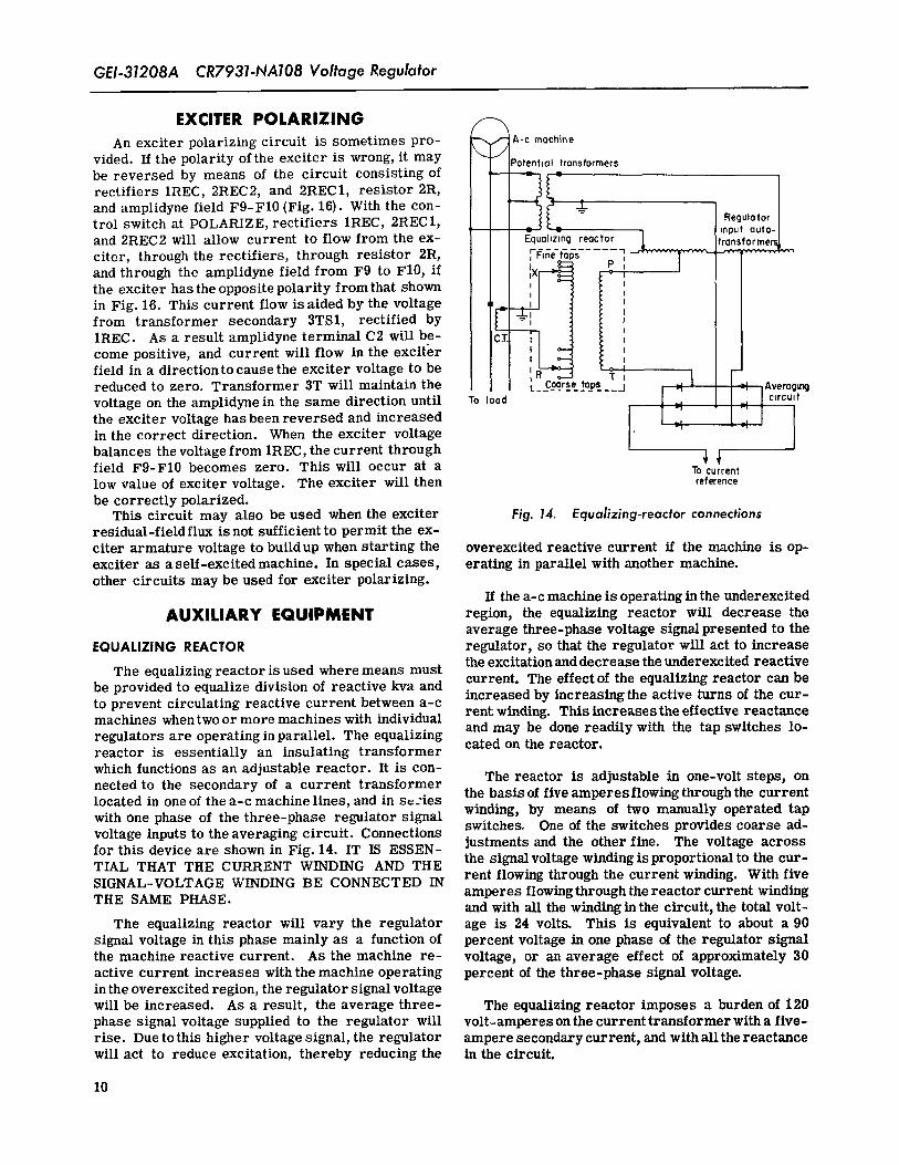
average three-phase voltage signal presented to theEQUALIZING REACTOR regulator, so that the regulator will act to increase
the excitation and decrease the underexcited reactiveThe equalizing reactor is used where means must current. The effect of the equalizing reactor can be
be provided to equalize division of reactive kva and increased by increasing the active turns of the cur-to prevent circulating reactive current between a-c rent winding. This increases the effective reactancemachines whentwo or more machines with individual
and may be done readily with the tap switches lo-regulators are operating in parallel. The equalizing coted on the reactor.reactor is essentially an insulating transformerwhich functions as an adjustable reactor. It is con-nected to the secondary of a current transformer The reactor is adjustable in one-volt steps, onlocated in one of the a-c machine lines, and in s_-ies the basis of five amperes flowing through the currentwith one phase of the three-phase regulator signal winding, by means of two manually operated tapvoltage inputs to the averaging circuit. Connections switches. One of the switches provides coarse ad-for this device are shown in Fig. 14. IT IS ESSEN- justments and the other fine. The voltage acrossTIAL THAT THE CURRENT WINDING AND THE the signalvoltage winding is proportional to the cur-
rent flowing through the current winding. With fiveSIGNAL-VOLTAGE WINDING BE CONNECTED INamperes flowing through the reactor current winding
THE SAME PHASE. and with all the windingin the circuit, the total volt-The equalizing reactor will vary the regulator age is 24 volts. This is equivalent to about a 90
signal voltage in this phase mainly as a function of percent voltage in one phase of the regulator signalthe machine reactive current. As the machine re- voltage, or an average effect of approximately 30active current increases with the machine operating percent of the three-phase signal voltage.in the overexcited region, the regulator signal voltagewill be increased. As a result, the average three- The equalizing reactor imposes a burden of 120phase signal voltage supplied to the regulator will volt-amperes on the current transformer with a five-rise. Due to this higher voltage signal, the regulator ampere secondary current, and with all the reactancewill act to reduce excitation, thereby reducing the in the circuit.
10
CR7931-NA108 Voltage Regulator GEI-31208A
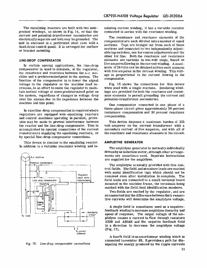
The equalizing reactors are built with two inde- sulating current winding, it has a variable resistorpendent windings, as shown in Fig. 14, so that the connected in series with the reactance winding.current and potential-transformer secondaries are
The resistance and reactance elements of theelectrically separate and both may be grounded. The
compensator are each divided into anumber of equalunit is enclosed in a perforated steel case with adead-front control panel. It is arranged for surface sections. Taps are brought out from each of these
sections and connected to two independently adjust-or bracket mounting, able tap switches, one for coarse adjustments and the
other for fine. Both the reactance and resistance
LINE-DROP COMPENSATOR elements are variable in one-volt steps, based onfive amperes flowing in the current winding. A maxi-
In certain special applications, the line-dropmum of 24 volts can be obtained acYoss each element
compensator is used to simulate, at the regulator, with five amperes inthe current winding. Thisvolt-the reszstance and reactance between the a-c ma-
chine and a predetermined point in the system. The age is proportional to the current flowing in the
function of the compensator is to lower the signal compensator°voltage to the regulator as the machine load in- Fig. 15 shows the connections for this devicecreases, in an effort to cause the regulator to main- when used with a single machine. Insulating wind-lain normal voltage at some predetermined point on ings are provided for both the reactance and resist-the system, regardless of changes in voltage drop ance elements to permit grounding the current andover the system due to the impedance between the potential-transformer secondaries.
machine and this point. One compensator connected in one phase of a
In case line-drop compensation is requiredwhere three-phase circuit gives approximately 30 percentresistance compensation and 30 percent reactance
regulators are equipped with equalizing reactorsand control machines operating in parallel, provi- compensatio.n.sion may be made to prevent interference between This device imposes a maximum burden of 225the reactor and the line-drop compensator. This is volt-amperes on the current transformer with aaccomplished by special connections of the current secondary current of five amperes, and with all oftransformers supplying the equalizing reactors, or the reactance and resistance elements in the circuit.by special line-drop compensator connections.
This devzce is similar to the equalizing reactor. AMPLIDYNE GENERATORIn addRlon to a variable reactance winding and in-
The amplidyne generator is normally individually
r drivenby an induction motor, although other arrange---, > A-C machine ments are sometimes used. Separate instructions
j are suppliedfor the amplidyne.
__ 3otent,oltransformers The amplidyne lSUSUally provided with five con-
_- }i ] trol fields. TJae field and armature leads are marked
with metal identification tags which should not beRegulator
- ,nput auto-J removed even after installation is complete. TheL,ne-drop compensator I f__ronsformersJ, field leads are connected go a small terminal board
--InEuF,7,n_.... ', _ _ _ mounted on the machine frame, the terminals being
-_( r-_ Ti marked with the field-lead identification numbers.
_T--_ ii_Fi_l _' °1l_ Two fields are excited by the regulator, andare
so connected that the difference between their respee-: tive currents will determine the amplidyne voltage.
1C_rse: _7|taps_ o
C3
_}p A single field is sometimes used as a negative-' ._ e: _ _ i feedback winding to increase amplidyne linearity and
.... .I ...... _ '' - _ IAverog_ngTo load .4 fl [ c,rcuH speed of response. The output voltage of the am-
i d I plidyne causes a current to flow through resistors-, A20R and A20AR and the negative feedback fieldin a direction to decrease the amplidyne voltage
1 I (Fig. 17).To current
reference
A fourth field is an amortisseur winding which isconnected toresistor dR. It provides a path for dis-
Fig. 15. Line-drop compensator connections sipating the energy produced by the ripple currents
11
GEI-31208A CR7931-NA108 Voltage Regulator
I 152
A MATURE
$ iS)
m VOLTAGE· ill RE OUI:ATOR
CONTROL
_g SW I SWITCH
_141 149 IHT- INTERMEOIATE POSITION
P L OFF ON POi.' POLARIZE POSITION
TEST
TRANSFORMERS
(?I 104
3 · _ IORm - ii
PHASEROTATIONI-2-3
EXCITERFIELD RHEOSTAT
rss
(ES) ?
(AO)
:mOR:O,,,II
[t,,,,;i,1,,.t,,,,,1151 (131_ --111_4
1., ,,s iiir..tIRCi i i i
] 1211 ISI ISS 1121
_r°I R4 IRSo =
I l G TRC IS7
I17 IlO 181
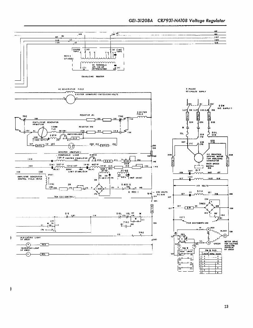
Fig. 16. Typical elementary diagram showing ampli- i?_ _ i?o?dyne and magnetic control circuits (T-9675110-1) ,_
12
GEI-31208A CR7931-NA108 Voltage Regulatori
ISE
14D 150 (6) IOQ
107 .o(2) I 07
IQO (I) lOS
09 a {3) IQ9
ICGARSE C IR} c (X) FINE I
(iF UBEI 1)
I (P) I
EQUALIZING REACTOR
I AC S PHASEGENERATOR FIELD
60CYCLESSUPPLY
XCITER ARMATURE-RATED ESO VOLTS
+
,Ds , ?
_I--- I 2$W
i {AC SUPPLY )(LI) 198 (L! 200 U.; [Rg
EXCITERFIELD
RESISTOR IRI TRC_ iTRC
AM PLIDYNE GENERATOR 204 206 205ARMATURE
COMM RESISTOR IR2 M
FLD I '
I J IOL 209 _' 20L208(Till
(SEE NOTE 4)_ _,i) 216_ - El T" ' 9F_OT_ JIBe _ t(T'_
(3o21 tat ,($o1lDO
(EXCITER Af_IATURE )AC INDUCTION Sol
· REMOVABLE LINKS D 2R H 142 42) EOB DRIVING MOTOR
I ST-P EXCITER STABILIZER _ DS_' _ FOR AMPLIDYNE140 I _ 196 210 D_ 211 142 GENERATOR
I4B(3'8) 'ST'P (3'G)197 (4'D) 4-ST'P D4R ;*_ c__L. _ CN£RSPEEO
140
., ' ,(:-:,)2,; ,.... E s.,.o.lsat) ( . )_i-_--I I I 142 OS136 {36) LIMIT STABILIZER :ST'S1 ST'S2 / ERR {Hit DIT
iiiiRi}_ · _ (HE) iRT
] (F(FiO) (4)_ / mAMPLIDYNEcoNTROLFIELDGENERATORF9FIO_-_((_t), 169 ["-- E3V-'I (Xl)
170 (NOT USED) 127 _m _ {X2) 128
2R 2 REG 2 lis VOLTS
ssI l 'TSl--t:::_ 72+ '?' * I--E% I-- ,4E2 REGI .I- 250 VOLTS (I) 3T-P (2)
(24)_/ DC BUS 127 m _ lES lei
SSW (DC CONTROL) 124 12T ·
16S
127 _ IE8
20L IOL {4} M 155 i54OS
UV
M TO lei TM iB--_ '''_ 1126 _'_FOR GUBTOMEN'S USE
'" I'_ ,,T __ll___172
HI RED
TRG BLAO_ lESHB
(IF USED) (26) _; LL MOTOR DBIV£
(_ R[_-_---} GREEN FOR VOLTAGEADJUSTING
INDICATING LIGHT RHEOSTAT
,,.UBEO, I I .....I-' USED.(_ I Ks I' _2 t _,
181 $ x
13
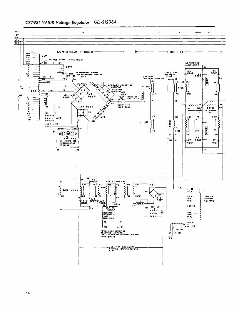
CR7931-NA108 Voltage Regulator GEI-31208A
152
150107105109
_' COMPARISON CIRCUIT "l _ FIRST STAGE PI{IS1
1121 AlT( Ill
IICI) _ VOLTAGE LEVEL ADaUETME NT(51 71 4 (2) AC WINDING5rtl IAI. {A2)(A3}(A4)
[61 11_5_ (A3TP J
{51 _ A 6(41 TO T ) TO SEGONDMY WINDINS STABILIEINS
(_,l II) tX O_ ON EQU__LIZIN6 REACTOR WINDINGS 'Iai ( IDI 6 m m) UIII'I CONTROL (_1Fz)
liS) IO_, IIOA WIN OIN GS(FS,FS,F?I 3_--(14) IFSI
% A_R_, 13_,;__ _VOLTAGERHEOSTATADJUETIN G 1
3 _ 20 (FSI
AtT ........ '_ /_, OECRE.E· '"' I .... '"--_"_DLTAG":AZm , (16! Al _ 3 cr_,: _ REH ITl (F?I
121
(.! -- 'l Icl e,_,,. _ -- '*('_.-.../(isI _ SENSITIVITY 141[[( 5!
'" IT IX seN5,,.....171 , 5 A, REGT _._// sE:s' OHMS
UO) ' 12l II I 4_ (1{
{ill 48V 7 AIX (F7)liE) A4T
'"' mi" 7 " "'MAGNETIC 5TANDARD
5
REGALIDRATNG. REGT.WINDING
I I
36 3111 AGI'll WINDING CONTROLWI HDING
A2X A55 25
Z, 751¢A., ...l_ ,A,I ?E (FZl 5(PStAl8 DIAGRAM_0%_-AI? IRECT.'I;-'q7 I I T-95TSnO-_
la"CT. I IR£OT'J [_A'A,R, ?1
1141 (13) 27
EO%A 3'_ LI2 I TO%
_18V A C_ E5 %
l:) 1" '°°'(ID) {4S) 32
is)FROM URGE EEXC_TE5REACTIVE AMPEREL IM IT DI A6 RAM TERMINALS (7) 8,{8l
T'9675110 °5 29
AMPLIFIER FOR UN DEREXCITED REACTIVE AMPERELIMIT
14
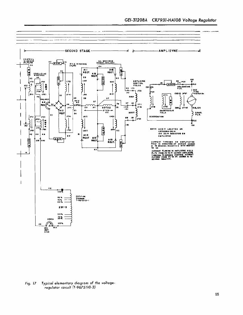
GEI-31208A CR7931-NA108 Voltage Regulator
I' SECOND STAGE ,.1 I" AMPLIOYNE ,4
_OMTROLNDIN S C. WINDINGS
STABILIZING
151
SMPI. IDYNE [--_ ll_,)14,1 [GONT ROL _. .Aa)(F21 FI EL OS 7' (lit
I 7I _31 ,B5 FLD.POLARIZIN6SEESlag
[IFSI I:[_ 13SIligl_T'B_TSll04(Fro ISll_ (IKIO) (A3_ loll
AM ONTISS EURFIELD GOIR.
FLD.DEGENERATION
;Z}
[GI Iqe
NOTE: A20 S LOCATED OH
llSTDllONA lOS Gl
GS 20-L%. SESISTOR ONAM PLI DYNE
CURRENT THROUGH AN AMPLPIOYNEFIELD IH DIRECTION OF aRROW CAUSESAl TO BECOME NEGATIV E WITH RESPEOTTO O2
GURRENT _I.0WIHi IN AMPLIOYHE FIELD
FIoF2 FROM F2 TO FI CAUSES AMPLIDYNETERNINALTO BEOOME pOSITIVE GURI_NTFLOWING FROM F$ TO F4 GAi_E_ At TOBEGONE NEGATIVE.
46
%o;2ST-P ON
85 % DIAGRAM70% T*SB7SIIO' I50%
2ST-S
50%
70% --
DSRH es,/,
44 ._ ;-100%EEC 44AANK
STAB
Fig. 17 Typical elementary diagram of the voltage-regulator circuit (T-9675110-2)
15
GEI-31208A CR7931-NA108 Voltage Regulator
in the control fields which might result in improper lator and the amplidyne generator. Multi-contact,operation, dead-front, switchboard-type, cam-operated control
A fifth field is sometimes used as a polarizing switches are generally used for control of the regu-lator circuits. These switches are used for transferwinding used in conjunction with the control circuit and control functions, and may be supplied with fixedfor polarizing the exciter, handles, or with removable handles where protective
The current rating and number of turns of each interlocl_ing is required.field is indicated on the amplidyne nameplate.
A motor starter is provided in cases where theThe armature leads are marked A1 and C2 and amplidyne is supplied with an individual driving
the polarity of the leads will depend upon the mag- motor. This starter is generally equipped with anitude and direction of current flow through the am- fusible disconnect switch. The starter magneticplidyne fields. Current flow through any field in the switch is a three-pole d-c operated device with over-direction of the arrow (except field Fl-F2, Fig. 17) load relays,will cause armature terminal C2 to become positive.
A transfer contactor is usually provided forThe amplidyne motor-generator set is usually switching the amplidyne in and out of the exciter-
equipped with an overspeed switch having a normally field circuit. It has both normally open and normallyclosed contact which is usually set to open at 150 closed main contacts.percent of rated speed. Overspeeding might occurif the driving motor were disconnected from the To protect against the possibility of establishingline, and the amplidyne left connected in the exciter a serious amplidyne short circuit through the nor-field circuit so that it op_.rates as a d-c motor. The mallyopenandnormallyclosedcontactsofthe trans-
fer contactor, a current-limiting resistor is supplied.switch contact is r_tedat 110 volts, 10 amperes, a-c;110 volts, 0.3 ampere, d-c; or 220 volts, 0.15 am- This resistor is usually composed of several re-sistance units assembled with mounting brackets.pete, d-c. The resistance used depends upon the installation.
A zero-center d-c voltmeter is usually suppliedCONTROL EQUIPMENT for connection across th'e amplidyne terminals.
The regulator equipment usually includes the The various control devices are covered by in-components required for the control of the regu- dividual instructions.
INSTALLATION
LOCATION AND MOUNTING armature connections will be appreciably greaterand will vary depending upon the ratings of these
The regulator components are usually supplied units.in an enclosing case designed for floor mounting.This enclosure should be installed in a well-venti- Amplidyne driving motors may in some cases be
lated, clean, dry location where the normal ambient connected for either of two voltages and the properconnections for the appropriate voltage must be madetemperature is not greater than 50 C (122 F). to avoid damaging the motor. Rotation of the am-
All of the equipment should be readily accessible plidyne should be investigated to determine that itfor adjustment and testing. The amplidyne should be is in the proper direction.located to permit easy inspection and maintenance.
CONNECTIONS POLARITYAND PHASEROTATION
Connections must be made in accordance with the When making connections from the exciter arma-diagrams supplied with the equipment for each par- ture leads to the regulator, polarity should be care-ticular installation. Care must be exercised to fully checked to make certain that the connectionsdetermine that the connections are correct to avoid are the same as those shown in the applicable dia-
damaging the equipment. Interconnecting wires will gram. The amplidyne arniature lead marked A1conduct a maximum current of approximately five must be connected to the positive side of the exciter
amperes in all regulator circuits. Maximum current armature circuit and terminal marked C2 to thein the amplidyne driving motor lines and amplidyne positive side of the exciter field circuit.
16
CR7931-NA108 Voltage Regulator GEI.31208A
Amplidyne field polarity shouldbe checked at the of the amplidyne fields and the amplidyne armatureregulator terminals. For this check it is possible voltage ratings. Polarities should be as previouslyto use a small dry cell or other source which will described; if discrepancies exist, the amplidynedeliver a voltage not in excess of two volts, field leads must be interchanged to obtain the cor-
rect polarity at the armature terminals.Amplidyne armature polarity should be deter- Equalizing-reactor and line-drop compensator
mined with a portable voltmeter directly at the am- polarities must be carefully observed when connec-plidyne terminals, tions are made. THE CURRENT TRANSFORMERS
The amplldyne must be operated disconnected USED WITH THESE UNITS MUST BE LOCATEDfrom the exciter field circuit to make this test, and IN THE SAME PHASE AS THE SIGNAL-VOLTAGEcare should be taken to avoid exceeding the ratings WINDINGS.
INITIAL OPERATION, TESTING AND ADJUSTMENT
CONTROL CIRCUITS previously described tests must then be conductedon each equipment by turning the transfer switches
Control circuits should be tested under such to the proper positions to place the regulators suc-conditions that the regulator will not affect the op- cessively under control of the respective controleratton of the a-c machine. First, turn the regulator switches.control switch to OFF and energize the control-power supply. Under this condition the amplidyne- Occasionally regulator control circuits are inter-driving motor-starter magnetic switch, and the locked with the exciter circuit breaker opening andtransfer contactor should remain de-energized. The closing the control circuits, either with or withoutregulator-control switch then may be turned to the use of relays. These circuits must be carefully
tested by operating the circuit-breaker controlTEST. The motor-starter magnetic switch shouldbe energized and the switch should close but the switches and the circuit breakers themselves to as-transfer contactor should remain in the de-energized certain that all details of operation are correct.
position. The switch may then be turned to ON, the In general, control circuits are arranged to pre-transfer contactor should be energized and should vent placing two regulators in service with one a-coperate to place the amplidyne in series with the machine and exciter, and to prevent placing a singleexciter field circuit. The switch may be returned regulator in service with an exciter operating into TEST to determine that the transfer contactorwill parallel with a second exciter on the same a-c ma-be properly de-energized and the motor-starter mag- chine field. The regulator diagrams must be care-netic switch wiU remain closed. Turning the switch fully studied to determine what control functions areto OFF should de-energize the magnetic switch, provided, and no further tests should be made until
The overspeed-switch circuit should be checked the control circuits have been completely tested.after placing the control switch at ON to energizethe motor-starter magnetic switch and transfer REGULATORcontactor. Disconnect one overspeed-switch leadterminal on the motor amplidyne set. This should PRELiMiNARYde-energize the motor starter and transfer con-tactor. The control switch should be left at ON and The regulator should be tested with the a-c ma-
chine operating at normal speed and voltage, and inthe lead reconnected; the devices should not be re-energized, the case of a generator, at no load and disconnected
from the system. The underexcited r eactive-ampereSome installations involve two or more regulator limit should be removed from service by disconnect-
equipments consisting of normal equipments and lng its d-c output circuit at terminal _ (Fig. 18).spare equipments for a single or several a-c ma-
If an equalizing reactor and line-drop compensatorchines. In such instances, transfer switches areare used, their adjusting knobs should be turned to
frequently provided for selection of the proper regu-lator. If these switches are equippedwith removable the zero position.handles for protective interlocking, all handles butone of each type must be immediately removed and VOLTAGE-ADJUSTiNG UNiTstored in a remote location to prevent incorrect and The regulator control switch should be kept atdangerous operation of the regulator equipment. The OFF until the a-c machine has been started and
17
CR7931.NA108 Voltage Regulator GEI-31208A
,so i'_'o NOTES
!o?
io5 '(_ __ 1 THE VOLTAGE REGULATOR CONTROL SWITCH (SW)
,os p__l 'v I5 PROVIDED WITH FIVE POSITIONS.
CR?9_KAKJ4GI A. WITH THE SWITCH AT "OFF," THE REGULATOR_EACTWEAUP_Rg LmBT PAHgL 1R OUT OF SERVICE.
n) (zl B. WITH THE SWITCH AT "TEST, 'lTHE REGULATOR
I P.I z IS ENERGIZED FOR ADJUSTMENT ONLY; AND IS(,_ IZ] NOT ACTUALLY IN SERVICE.
B3T
C. WITH THE SWITCH AT "ON," THE REGULATOR
la_,1 t 141 tGI IS IN SERVICE. IF POLARITy OF EXCITER ARMA-TURE IS REVERSED FROM THAT SHOWN IT CAN
n BE CORRECTED THUS'
14l {Z} D. WITH THE SWITCH AT "INTER," THE A-C
IO_ I_J L,M,T IIoo_ MOTOR-AMPLIDYNE GENERATOR SETISSTARTED.
3 _3) 0150RgSISTORg3. TAP CON DiAL E. WITH THE SWITCH AT '*POLARIZE," THETO Bg OLq'_........ _,}aL rj 1 , POLARITY OF EXCITER VOLTAGE IS COR-
TgSTmG OC,T. I I / RECTED.(os OIALPt.ATg) 2. TRANSFORMER PRIMARIES AND SECONDARIES ARE
B3R 9 NOT NECESSARILY SHOWN ADJACENT BUT ARE
3. THE COMPENSATING AND MAIN CONTROL FIELD
WINDINGs OF THE AMiDLIDYNE HAVE THE SAMEMAGNETIC AXIS AS THE LOAD CURRENT IN THEARMATURE.
14) _-_ 4 THE AMPLIDYNE GENERATOR ARMATURE LEADS
ARE MARKED A1 AND C2 AND WHEN THE GEN-
II¢,,o, 3_ ¥_, ERATOR IS RUNNING THE POLARITY OF THE LEADSWILL DEPEND UPON THE MAGNITUDE AND DIREC-
pOW£R.gcALm_ATZ0. TION OF CURRENT FLOW THROUGH THE AMPLI-
I _o . 12 DYNE CONTROL FIELDS. CURRENT FLOW TH]ROUGH
II Itt Pal IZ] [411111 PRI [g] ANY FIELD IN THE DIRECTION OF THE ARROW' _ WILL CAUSE AMPLIDYNE TERMINAL A1 TO BE-
B2T _ ,","v-w--_ BIT COME NEGATIVE AND C2 TO BECOME POSITIVE.
1 i;_ 14JII SIC 14!17 iG is 14
.... ?2 :: ::BE .,. B_'X BIRH BiX · T.... T.... "'"
I ... l,o_, '7 It ,ch-q t' ............
"_ o (71 oig)
g,}
T.g&75IK)-2 Is
;41 _l$1
-- -- -- 1'/9 --
,-,='L_mm,3-:,:.?,D ORANGgRED OlM#_
SECONDARIESOFLIIqTSTABILIZEII$35T- _$T
Rev 1
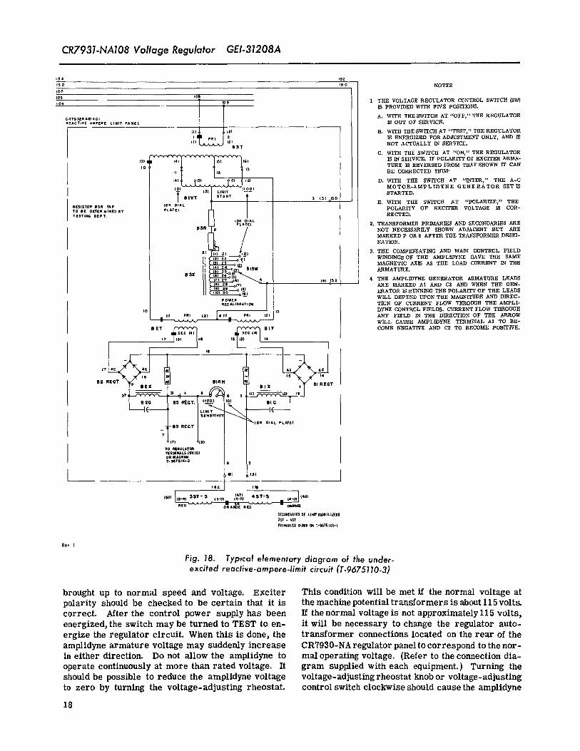
Fig. 18. Typical eJementcrrydiagram of the under-excited reactive-ampere-limit circuit (1'-9675110.3)
brought up to normal speed and voltage. _.xciter This condition will be met if the normal voltage atpolarity should be checked to be certain that it is the machine potential transformers is about l l Svoltacorrect. After the control power supply has been If the normal voltage is not approximately 115 volts,energized, the switch may be turned to TEST to en- it will be necessary to change the regulator auto-ergize the regulator circuit. When this is done, the transformer connections located on the rear of theamplidyne armature voltage may suddenly increase CR7930-NA regulator panel to correspond to the nor-in either direction. Do not allow the amplidyne to mai operating voltage. (Refer to the connection dia-operate continuously at more than rated voltage. It gram supplied with each equipment.) Turning theshould be possible to reduce the amplidyne voltage voltage-adjusting rheostat knob or voltage-adjustingto zero by turning the voltage-adjusting rheostat, control switch clockwise should cause the amplidyne
18
GEI-31208A CR7931-NA108 Voltage Regulator
voltage to increase in the boost direction so that the the signal voltage after they have been adjusted. Re-amplidyne voltmeter needle will move to the right adjustment may also be required following the ad-(boost direction)andamplidyneterminal C2 will be- dition or removalof equalizing reactors or line-dropcome negative with respect to Al. Turning the volt- compensator, s.age-adjusting rheostat knob or voltage-adjusting con-trol switch counterclockwise should cause the am- ADDITIONAL CONTROL-SWITCH CIRCUITSplidyne voltage to increase in the buck direction
Where additional control, transfer, or exciter-If the operation of thevoltage-adjustinguntt must polarity reversing switches are used, the previous
be reversed because the operation is not as described tests should be repeated, with these switches ad-or because reverse operation is desired, turn the justed for all operating conditions, to determine thatcontrol switch to OFF, and transpose the end con- the amplidyne voltage may be properly controllednection of the jumper connecting the center arm to with the voltage- adjusting unit when eachof the reg-the end of the resistance element, ulator control switches is at TEST. This will indi_
cate that all switch connections are correct.VOLTAGE LEVEL
It is possible that operation of the voltage-adjust- POLARITY TESTSing rheostat or switch will have no noticeable effect Before the regulator is first placed in control ofon the amplidyne voltage when the regulator is first machine excitation, it is recommended that finaltested, polarity tests be conducted,
Inability to control the amplidyne voltage may be Amplidyne polarity should be checked as follows:due to the signal voltage falling outside of the regu- with the regulator control switch at OFF, short cir-lator range: ff the amplidyne voltage is too high in cult the normally open contact on the transfer con-the buck direction, the signal voltage may be too tactor which is connected between amplidyne-arma-high; if the amplidyne voltage is too high in the boost ture terminal A1 and the exciter-field rheostat, ordirection, the signal voltage may be too low. The occasionally between A1 and the positive side of theregulator is normally connected for a nominal signal exciter armature. This can be done with a smallvoltage of approximately 115 volts but usually can be wire, since the shorting connection will not be re-adjusted for nominal signal voltages from 85 to 140 quired to carry current. Connect a d-c voltmetervolts by use of the taps on the autotransformers, between the amplidyne-armature terminal C2 andThe voltage-adjusting rheostat will usually provide the negative side of the exciter armature, with theadjustment of 10 percent above to 10 percent below positive voltmeter lead on C2. These connectionsthe nominal signalvoltage. The signal-voltage supply may be made with the a-c machine and exciter inshould be connected to autotransformer taps cdr- operation if the necessary precautions are taken.responding to the appropriate voltage as given inthe table shown on the connection diagram provided With the a_c machine operating at normal speedwith the equipment. A higher signal voltage requires and voltage, turn the regulator control switch tothe use of higher numbered taps. Taps of the same TEST and adjust the amplidyne-armature voltage tonumber should be used on each transformer, zero with thevoltage-adjusting knob or switch. The
voltage indicated by the previously connected testCHANGE TAPS ON AUTOTRANSFORMER ONLY voltmeter should be equal to that portion of the ex-
WHEN THE REGULATOR CONTROL SWITCH IS citer voltage which is impressed acrossthe exciterSET AT "OFF." field. Turn the voltage-adjusting knob or switch in
the raise direction to increase the amplidyne voltageFinal connections should be made whichwill per- in the boost direction. The test voltmeter should
mit adjustment of a-c machine terminal voltage over indicate the total of the exciter-field and amplidyne-the desired range by use of the voltage-adjusting armature voltages. Then turn the voltage-adjustingrheostat. If nominal voltage is not obtained when knob or switch in the lower direction to increase
the voltage-adjusting rheostat is in its midposition, the amplidyne voltage in the buck direction. Theresistor AiR (Fig. 17) may be increased or de- testvoltmeter should indicate the difference between
creased so that the voltage-adjusting rheostat is in the exciter-fieldvoltage andthe amplidyne-armaturethe midposition with a-c machine nominal voltage, voltage.
It is usually preferable to delay the final voltage- If the above tests are not satisfactory, connectionslevel adjustment until the underexcited reactive- must be carefully checkedand proper operation ob-ampere limit has been reconnected, since it may rained before any further tests are made.affect the voltage-adjusting rheostat setting for agiven voltage. In addition, the equalizing reactor Before proceeding it is necessary to check theand line-drop compensator may appreciably alter polarityof the stabfiizing transformers in the follow-
19
CR7931-NA108 Voltage Regulator GEI-31208A
ing manner. With the control switch at TEST and preciably, immediately turn the control switch tothe a-c machine operating at normal speed and volt- OFF and determine the cause of incorrect operation.age, adjust the voltage-adjusting rheostat until theamplidyne is delivering about 150 volts in the boost A sudden and large change in amplidyne voltagedirection. Carefully disconnect one primary lead may mean incorrect amplidyne polarity or equaliz-of the amplidyne stabilizer (refer to the connection ing reactor polarity. The ampUdyne and equalizingdiagram supplied with the equipment). Removing reactor polarity checks should be repeated beforethis lead should cause the amplidyne voltmeter to again placing the regulator in control of the a-c ma-chine excitation.momentarily increase in the boost direction; replac-ing the primary lead should momentarily decrease If the amplidyne exhibits a gradual change inthe amplidyne boost voltage, voltage resulting in oscillations which grow steadily
If conditions are as outlined above the amplidyne greater, the stabilizing connections or adjustmentof the stabilizing circuits may be incorrect. The
' stabilizer has the correct polarity, polarity of the stabilizing transformers shouid beTo check the polarity of the exciter stabilizer rechecked. If after all polarity connections have
proceed as follows. With the exciter operating at been rechecked, the amplidyne voltage oscillatesnot less than 25 percent of rated voltage, disconnect when the controlswitch is placed at ON, remove theone of the primary leads of the exciter stabilizing regulator from service. Now attempt to obtain stabletransformer. This shouldmomentarily increase the operation by adjusting the resistor-rheostat com-amplidyne boost voltage; replacing the exciter stabi- bination in series with the exciter stabilizing trans-lizer primaryleadshouldmomentarily decrease the former primary. First, increase the resistance inamplidyne boost voltage, series with the exciter stabilizer primary approxi-
Equalizing reactor polarity must be checked be- mately 15 percent. Again place the regulator infore putting the regulator in service with a machine control of the a-c machine excitation. If the stability
has not improved, reduce the resistance in serieswhichis connected to the system. Turnthe equalizing with the exciter stabilizer primary ton valuethat isreactor-adjusting knobs to the zero position and op- about 15 percent less thanthe originalvalue andagainerate the machine overexcited at normal voltage, place the regulator in control of the a-c machineWith the regulator-control switch at TEST, adjustthe amplidyne voltage to zero with the voltage-ad- excitation. If the stability still has not improved,repeat the preceding adjustment using larger andjustingrheostat. Turn the equalizing reactor coarse- smaller values of resistance. It should be possibleadjusting knob to the right to insert reactance. Theamplidyne voltage should increase in the buck direc- to stabilize the regulator by gradual adjustments oftion. If the voltage increases in the boost direction, this resistor-rheostat combination. However, if thethe potential circuit leads to the equalizing reactor regulator still is unstable after the fuU range of re-must be reversed and the tests repeated. When the sistance has been tried, the taps on the exciter stabi-
lizer transformer secondary should be changed inpolarity of the equalizing reactor is correct turn 15,percent steps. (Refer to the connection diagramboth knobs to zero and set the fine-adjusting knobat 5. It is then possible to proceed with the regula- supplied with the equipment.) After each tap changethe resistance in series with the exciter stabilizertor tests, should be adjusted in the same manner as previously
INITIAL OPERATION described.NOTE: ALL ADJUSTMENTS MUST BEIt is recommended that the following tests be MADE WITH THE CONTROL SWITCH
made with the a-c machine disconnected from the AT _OFF'.load or system; if the a-c machine must be connectedto the system, it should be operated at a light load. In general, stability difficulties are more likelyFor complete information on placing the regulator to appear at reduced excitation than at normal a-cin service and removing it from service, refer to machine excitation. Therefore it is usually possiblethe section titled "Operation." to obtain satisfactory stability under loaded condi-
With the a-c machine operating at normal speed tions, if satisfactory stability is obtained at no load.and voltage and with the regulator-colltrol switch atTEST, adjust the amplidyne voltage to zero. The NOTE: SATISFACTORY STABILITYcontrol switch may then be turned to ON. This will MUST BE SECURED BEFORE FURTHERTESTS ARE CONDUCTED.place the amplidyne in the exciter-field circuit andthe regulator in control of the a-c machine excitation. With the regulator-control switch at ON, turn theThe amplidyne voltage should not change more than voltage-adjusting knobor switch in the raise direc-about 20 volts and should immediately return to tion; the amplidyne voltage should change slightlynearly zero. If the amplidyne voltage changes ap- in the boost direction and the exciter armature volt-
20
CR7931-NA108 Voltage Regulator GEI-31208A
age and a-c machine terminal voltage should rise. SWITCH TO "OFF," and follow the procedure out-Now turn thevoltage-adjusting knob or switch in the lined under "Initial Operation."
lower direction; the amplidynevoltage should change REGULATOR SENSITIVITY AND VOLTAGEin the buck direction and the exciter and a-c ma- REGULATIONchine terminal voltage should fall. If the a-c ma-chine is a generator which is not connected to a load Determination of a-c machine voltage regulationor a system, the voltage-adjusting rheostat may be with the regulator in service is adifficult procedureoperated to obtain a total change in machine voltage under usual operating conditions and one which will
produce only qualitative results. Since the regulatorof about 20 percent of ra_ed voltage, is adjusted at the factory to provide adequate sensi-
Operation of the voltage regulator may also be tivity for close regulation, this measurement is
tested by changing the resistance of the exciter-field usually unnecessary at the time of installation, andrheostat. As the rheostat resistance is decreased, for this reason no special test procedure is given.the amplidyne voltage should change in the buck di- After the equipment has been placed in service, itrection; as resistance is increased, the voltage is possibleto ebtaindata which will provide a meas-should change in the boost direction. No appreciable ure of voltage regulation, but results must be care-change in exciter voltage should occur, fully interpreted to gain a reliable estimate of per-
formance.
Refer to the section titled _Operation" for in-structions on removing the regulator from control If the machine is connected to a system, the
regulation will depend to a great extent upon theof machine excitation, characteristics of this system. Regulation will also
Where additional control, transfer, or exciter- be considerably affected by the use and adjustmentpolarity reversing switches are used, the previous of equalizing reactors and line-drop compensators.
tests should be repeated with these switches ad- Furthermore, the sensitivity of the regulator itselfjusted for all operating conditions to determine that will be a major factor affecting voltage regulation.
the a-c machine excitation may be properly con- If it is desired to improve regulation and thetrolled with the regulator. This will assure the cor-rectness of all switch connections, response of the regulator to transient disturbances
by increasing the regulator sensitivity, the sensi-When proper regulator operation has been se- tivity-adjusting rheostat may be used for this pur-
cured, optimum stability should be checked and the pose. This should be done cautiously in steps ofnecessary adjustments made. no more than 100 ohms at a time, with the regulator
out of service. Decreasing resistance will not onlyOPTIMUM REGULATOR STABILITY increase sensitivity, but may produce stability dif-
ficulties which will only appear at Iow values of a-cThe following test should enable a quick determi~
machine excitation current, such as are encounterednation of optimum stability. With the regulator in
under no load or underexcited conditions. Changescontrol of a-c machine excitation:should, therefore, be made carefully, and the stability
1. The amplidyne voltmeter will indicate only should be checked with the a-c machine at no loadtwo or three oscillations after suddenly turning the or light load after each change. If necessary, sensi-voltage-adjusting rheostat a few degreesin thelower tivity may be reduced toincrease regulation or im-
prove stability by increasing the resistance of thedirectiom sensitivity-adjusting r e s i s t o r as previously de-
2. After suddenly turning the voltage-adjusting scribed.rheostat a few degrees in the lower direction, thea-c machine voltmeter will overshoot only slightly UNDEREXCITED REACTIVE-AMPERE LIMITbefore returning to a new steady value.
LIMIT POLARITYOptimum regulator stability can usually be ob-
tained by following the procedure outlined in "Initial After satisfactory operation of the regulator hasOperation." However, in some instances, it may be been obtained, the reactive-ampere limit shouldbedesirable to follow a similar procedure with the tested. Set the REACTIVE-AMPERE-LIMIT SENSI-amplidyne-stability primary resistance, and second- TIVITY dial at zero. Set the REACTIVE-AMPERE-
ary taps, to improve the regulator stability. In ad- LIMIT POWER RECALIBRATION switch at zero.dition, changing the taps on the reactor in series Set the REACTIVE-AMPERE-LIMIT START dialatwith the exciter stabilizer secondary may improve its highest numbered position. Reconnect the limit
stability in certain cases, d-c output circuit at terminal 7 (Fig. 18).
Before making any adjustments in the stabilizer With the machine carrying power load and some
circuit, it is necessary to TURN THE CONTROL safe value of underexcited reactive current, move
21
CR7931-NA108 Voltage Regulator GEI-31208A
the regulator control switch to TEST. Adjust the INITIAL OPERATION
voltage-adjusting rheostat for zero amplidyne volts. Turn the REACTIVE - AMPERE - LIMIT START
SlowlyturntheREACTIVE-AMPERE-LIMIT START dial to its highest reading. Readjust the amplidynedial toward zero. At sortie setting of the dial, the voltage to zero with the voltage-adjusting rheostat,amplidyne voltage will increase in the boost direc- if necessary. Operate the a-c machine at normaltion. If the amplidyne voltage does not increase ap- voltage andwith underexcited reactive current. Turnpreciably before the dial has been turned to zero, the reguLator control switchtoONasdiscussed underreturn the dial to the highest-numbered position.Decrease the a-c machine excitation to further in- "Initial Operation." Slowly turn the REACTIVE-
AMPERE- LIMIT START dial toward zero. Thecrease the underexcited current, being careful notto exceed the safe operating limit for the machine, amplidyne voltage should increase slightly in the
boost direction and the exciter voltage should in-crease causing the underexcited reactive current to
Again tu r n the RE ACTIVE - AMPERE - LIMITdecrease. The dial setting at which the underexcited
START dial toward zero. The point at which thereactive current starts to decrease is the limit-
amplidyne vo-ltage starts to move from zero is con- start point, tf the operation is not as described, ira-sidered the limit-start point. Continue turning the mediately remove the regulator from control of thedial until the amplidyne voltage is 20 volts boost.If the amplidyne voltage cannot be increased from a-c machine excitation by turning the regulator-zero by turning the limit-start dial to zero, the limit control switch to OFF. Repeat the limit polarity
tests. Do not proceed further until satisfactory op-polarity may be reversed. Turn the regulator con- oration is obtained.trol switch to OFF and reverse the primary connec-tions of transformer B3T (Fig. 18). Repeat the tests With the reguLator-control switch at ON, and thepreviously described to determine if a boost am- REACTIVE- AMPERE -LIMIT START dial at theplidyne voltage can be obtained by turning the limit- limit-start point, observe the amplidyne voltmeter,start dial toward zero. THIS TEST MUST GIVE the exciter voltmeter, and the a-c machine ammeterPROPER RESULTS BEFORE FURTHER TESTS for signs of oscillation. If oscillations of the reac-ARE CONDUCTED. tire current or amplidyne voltage appear, remove the
regulator from control of the a-c machine excitation
If the amplidyne voltage increases from zero in byturning the regulator controlswitch to OFF. Ad-the buck direction, the limit d-c output may be re- just the resistance in serieswtth the primary of theversed. Reverse the connections to limit terminals limit stabilizing transformers in 15 percent steps,
7 and 8 (Fig. 18). Repeat the previously described firstinthedirectionto decrease resistance and thentests to secure proper results, in the direction to increase resistance. After each
of these adjustments repeat the procedure for putting
With the REACTIVE - AMPERE - LIMIT START the limit in service as previously described, being
dial so set that the amplidyne voltage is 20 volts in very careful to observe the amplidyne and exciterthe boost direction, turn the POWER RECALIBR A- voltage oscillations and reactive current oscillations.TION tap switch from zero toward point 9. If the After stable operation of the limit has been ob-a-c machine is delivering power, the amplidyne rained, check the limit operation as follows with thevoltage should increase in the boost direction as the regulator in control of a-c machine excitation; movePOWER RECALIBRATION switch is turned toward /he REACTIVE-AMPERE-LIMIT START dialto the
point 9. limit-start point. Record the reactive current. De-
Turn the POWER RECALIBRATING REACTOR crease the underexcited reactive-ampere load on thea-c machine by operating the voltage-adjusting rheo-
switch to zero. Readjust the amplidyne voltage to stat to raise the voltage. The underexctted reactive20 volts boost with the RE ACTIVE - AMPERE - LIMITcurrent should decrease. It should be possible to
START dial. Before proceeding further with the adjust the underexcited reactive current to any valuetests on the underexcited reactive limit circuit, it lower than it was at the limit-start point. Now in-
is necessary to check the polarity of the reactive- crease the underexcitedreactive current, by turningampere-limit stabilizing transformers. Carefully the voltage-adjusting rheostat to lower the voltage.disconnect one of the primary leads of a limit stabi-
As the limit-start point is passed, the amplidynelizing transformer (refer to the connectiondiagrams voltage should increase in the boost direction and itsupplied with each equipment). This should cause should be impossible to raise the reactive currentthe amplidyne voltage to increase in the boost direc-
appreciably above the previously recorded value notion. Replacing the primary lead should cause the matter how far the voltage-adjusting rheostat isamplidyne voltage to change in the buck direction, turned in the direction to lower voltage.Do not proceed with the underexcited reactive-am-
pere-limit tests until the poLarity of the limit stabi- As a final check of optimum limit stability, movelizer is correct, the REACTIVE-AMPERE-LIMIT START dial until
22
g_._a,(aLUDJodaLII so
luaw,_sn!po_31!/_sdo_(Jol_oaJ Bu!,mJcI
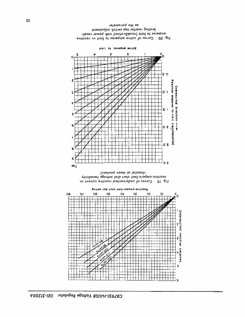
a^!,oDaJ'sA l!m!l oi saJadmo aA!,oo jo SaAdn._ '0_ 'B!:I
;tWll Ol seJeduJO eAIl3 v
g tr £ _ I 000
. /G//_g
..........- ,..- / ./ !; '0.-- // // / /// /I. ;o
._ / ' / / _ ./' /( //)' a)Q
£.- / / j/ //_.- /' /' / // o'i _ ,)e/' ./ / / // I -_
f / / // / / g,.t, / /
/' / / /// _
o.
M / ///// ;' l - -
g / / / /_,// // t / / _3o
/ j / -_/ L/9 /1 / / OB ;/ / /
/ / /z / / / _,
/ / _._g/ /'
J
' I6/i ' I 0'£
dD.l.
(uo!l!sod uoam in lotsoot_J
'sa lueddn3aA!_3oaJpe_!3xa_apun_o sa^JnD '6J 'B!._
_uulas iolp iJols llUJq-aJaduJO-aAll3oaN
Og OZ 09 OCj Ot_ 0£ 02 OI
(3.fl)
x
CL
g_g
C3
g(h
§
¥_,0_.1_'-1.,3_D ._oP31nBa_/aBnllOA 90IVN'I_6L_tD
CR7931.NA108 Voltage Regulator CEI-31208A
the amplidyne voltage is about 20 volts in the boost reactive-current input reaches three amperes withdirection. Abruptly move the voltage-adjusting rheo- four active amperes.
stat afew degrees in the lower direction and observe Fig. 19 indicates, that for an underexcited reac-carefully the amplidynevoltmeter and the reactive- rive current of tour amperes, the REACTIVE-AM-current ammeter for signs of oscillations. If os-
PERE-LIMIT START dial should be set at approxi-cillations appear, adjust for optimum stability as mately 47. This satisfies the requirement at zeropreviously outlined. When the amplidyne voltmeterand the reactive-current ammeter show only a few active amperes. Now, the number of reactive am-oscillations after an abrupt change of the voltage- peres necessary to start the limit at four active
amperes must be reduced by one reactive ampereadjusting rheostat, the limit stability is satisfactory, to obtain the desired power recalibration. There-Move the REACTIVE-AMPERE-LIMIT SENSITIVITY
dial slowly toward its highest scale reading. Again fore in Fig. 20, a value of one reactive ampererecalibration of the limit and four active amperes
check the limit stability, to the limit, indicates that tap switch B1SW shouldThis completes the preliminary adjustment of be set at tap 4.
the limit. Final adjustment can be made at any time.If desired, before making the final adjustment of
the limit, the calibration curves (Fig. 19 and 20)mayFINAL ADJUSTMENT OF LIMIT be checked in the following manner.
The final adjustment of the limit may be made by Place POWER RECALIBRATING REACTOR tapuse of Fig. 19 and 20, unless special calibration data switch B1SW on tap 8. Place the REACTIVE-AM-are supplied with the equipment. PERE-LIMIT START dial at its highest scale posi-
The limit-start adjustment is determined from tion. Put the regulator incontrol of thea-c machine
Fig. 19. This graph shows the value of the machine excitation. With the a-c machine carrying somecurrent-transformer secondary underexcited reac- convenient power load at about unity power factor,tire current which will cause the limit to operate move the REACTIVE-AMPERE-LIMIT START dial
as a functionof dial setting andnormal a-c machine slowly toward zero. At some position of the dial,potential-transformer secondary voltage. Values of the limit will start to operate. This position will bevoltages differing from those shown on the graph that which will just start to decrease the machinemay be easily interpolated. The POWER RECALI- underexcited reactive current, or increase the over-BRATING RE ACTOR adjustment is shown in Fig. 20. excited reactive current.This curve shows the amount by which the limit-
Determine the active and reactive amperes de-start point will be reduced below the limit-start
livered by the machine current transformer to theadjustment as a function of machine current-trans-
limit. Draw a vertical line from the active-ampere
former secondary active current for various values scale point in Fig. 20 to the curve for tap 8. Readof the tap-switch (B1SW) setting, the corresponding reactive amperes recalibration
The two following examples are given to illustrate of the limit, and the setting of the REACTIVE-AM-the method of setting the limit. PERE-LIMIT START dial.
In Fig. 19, use the dial setting and the properEXAMPLE 1. It is required that the limit should
a-c voltage curve to determine the value of under-start to function when the underexcited reactive-excited reactive current for which the limit is set.
current input to the limit reaches four amperes andthat the limit action be independent of the power From this value, subtract the reactive amperes re-component of current. The normal voltage on the calibration. The result should he essentially equalsecondary of the a-c machine potential transformers to the reactive amperes delivered to the limit if theis 110 volts, test has been carefully conducted.
Set the limit adjustments to the points which areFig. 19 indicates that for an underexcited reactive
desired for final operation. If it is desired to checkcurrent of four amperes, the REACTIVE-AMPERE-
the adjustments the following procedure may beSTART dial should be set at approximately 47. As
followed.canbe seen from Fig. 20, the tap switch onthe powerrecalibrating reactor must be set on tap 0, since Place the regulator in control of the a-c machinethe limit action is to be independent of the power excitation° Operate the machine at the desired powercomponent of current, load and at a reactive ioad which should not cause
limit operation. Turn the voltage-adjusting rheostatEXAMPLE 2. It is desired to have the limit in the direction to lower voltage until the limit pre-
start to function when the underexcited reactive- vents further reduction in machine overexcited re-
current input to the limit reaches four amperes active current, or increase in underexcited reactivewith zero active amperes, andwhenthe underexcited current. Determine the value of reactive current
24
GEI.31208A CR7931-NA108 Voltage Regulator
and active current supplied by the macMne current gized. When making adjustments, the a-c machine
transformer to the limit, power factor should swing toward unity as the re-actance of the equalizing reactor is increased.
Knowing the a-c machine voltage and the settingof the REACTIVE-AMPERE-LIMIT START dial,determine theunderexcited reactive current setting LINE-DROP COMPENSATOR
from Fig. 19. Determine the underexcited reactive Turn both adjusting knobs Lo zero, and operateamperes recalibration from Fig. 20. The result of the a-c machine at lagging power factor. With the
subtracting the value of underexcited reactive am- regulator control switchat TEST and the amplidyneperes read in Fig. 20 from the value of underexcited voltage adjusted to zero, turn the coarse reactance-
reactive amperes read in Fig. 19 will be essentially adjustment knob to the right to insert reactance; theequal to the value of underexcited reactive current amplidyne voltage should increase in the boost dj-to the limit at the limit-start point, rection. Return the reactance-adjusting knob to zero,
and turn the coarse resistance-adjusting knobto theEQUALIZING REACTOR right to increase resistance; this should also in-
AND LINE-DROP COMPENSATOR crease the amplidynevoltage in the boost direction.If the amplidyne voltage increases in the buck direc-tion during these tests, the compensator potential
EQUALIZING REACTOR leads must be interchanged and the tests repeated.The polarity of the equalizing reactor is checked
as described under "Initial Operation." Final ad- Final adjustment of the compensator must bejustment of the equalizingreactor can only be made made on the basis of experience. Preliminary ad-after considerable experience with the machine op- justment may be made in accordance with the knowneratingunder control of the regulator. It is desirable values of resistance and reactance for that portionto keep the amount of reactance used, to the minimum of the system over which compensation is desired.required for proper division of reactive kva between If the voltage at the point which is to be compensatedmachines, to avoid excessive voltage regulation. As decreases as the power factor becomes more laggingan initial adjustment, it is frequently desirable to and increases as the power factor becomes less lag-turn the fine-adjustment knob to position 5 with the ging, more reactance and possibly less resistance
coarse knob at zero. Adjustments may be made with may be required. Adjustments may be made withthe equalizing-reactor current transformer ener- the compensator and regulator in service.
OPERATION
NORMAL OPERATION Generators are frequently connected to the load orsystem before the regulator is used, but this is not
GENERAL essential since the regulator may be placed in service
with the machine under any load condition and withThe complete voltage-regulator equipment should the machine connected to or disconnected from the
be placed in normal service with the a-c machineonly after the control circuits, regulator, underex- system.cited reactive-ampere limit, equalizing reactor, The following procedure should be used to placeline-drop compensator, and maximum-excitation the regulator in control of machine excitation:
limit have been properly tested in general conform- 1. With the regulator-control switch at OFF, andance with the previously described instructions, with the a-c machine operating at normal speed, ad-Final adjustment of these units may, of course, be just the machine terminal voltage to approximatelydelayed until operating experience has been obtained, normal with the exciter-field rheostat. If the ma-but circuits which have not been thoroughly tested
chine is operating under loaded conditions or con-must not be employed with the regulator in service nected to the system, this step should not be neces-if the possibilities of damage to the equipment anddisturbance of the system are to be avoided, sary.
2. Turn the regulator-control switch to TEST.
OPERATION WITH ATTENDED EQUIPMENT 3. Adjust the amplidyne voltage to zero with the
In attended stations, the a-c machine is generally voltage-adjnsting rheostat or switch. If this cannot
brought up to normal speed and voltage under manual be done, do not proceed further until the trouble hascontrol before the regulator is placed in service, been determined and eliminated.
25
GEI-31208A CR7931-NA108 Voltage Regulator
4. Turn theregulator-controlswitch to ON. This operation in the case of a generator, and to avoidwill place the regulator in control of the a-c machine other serious disturbances for all types of a-c ma-excitation, chines.
5. The terminal voltage or excitation level of the The regulator may be removed from service anda-c machine may now be adjusted with the voltage- the a-c machine excitation returned to manual con-adjusting rheostat or switch as required for the trol under any load condition. The following proce-normal operating schedule, dure should be used for this purpose:
The regulator will successfully control the a-c 1. Adjust the amplidyne voltage to zero by usemachine excitation over the complete load range of of the exciter-field rheostat.
the machine with the exciter-field rheostat at a posi- 2. Turn the regulator control switch to OFF.tion whichwill give rated machine voltage at no loadwithout the regulator in service, or at a position With the regulator in control, the exciter-fieldwhich will give rated machine voltage at rated load rheostat may be adjusted as follows to bring thewithout the regulator in service, or at any inter- amplidyne voltage to zero:
mediate position. However, additional excitation 1. If the amplidynevoltage is in the boost direc-system realiability may be secured by the proper tion, slowly reduce the rheostat resistance until theadjustment of the exciter-field rheostat when the amplidyne voltage is zero. No appreciable changeregulator is in control of machine excitation, in exciter voltage or a-c machine voltage should
occur.For this purpose, it is recommended that imme-
diately after the regulator has been placed in service, 2. If the amplidyne voltage is in the buck dfrec-the field rheostat be adjusted to affd maintained at a tion, slowly increase the rheostat resistance. Nopredetermined position. This position should be such appreciable exciter or a-c machine voltage changethat the machine excitation will be sufficient under should appear.all normal a-c machine loads to give stable operationand avoid serious operating disturbances if the ex- OPERATION WITH UNATTENDED EQUIPMENT
citation s y st e m should be suddenly returned to In unattended generating stations, the regulatormanual control through an emergency, resulting in is generally in controlof a-c machine excitation andloss of control by the regulator. It is suggested that terminal voltage during the entire machine startingthis rheostat position be selected so that with the cycle. The regulator control switch is normally atexcitation system under manual control, it will pro- ON, and the exciter-field rheostat is adjusted induce from 3/4 rated to rated a-c machine field cur- accordance with the procedure given under "Opera-rent, with preference given to the latter value_ Where tion with Attended Equipment."the a-c machine is closely paralleled with other ma-chines equipped with automatic voltage regulators,without underexcited reactive ampere or minimum EXCITER POLARITY REVERSALexcitation limits, a position corresponding to thelowervalue maybe found more desirable. Rheostats INCORRECT POLARITY
are normally supplied with a position switch which If, when the a-c machine exciter is started at anymay be used in conjunction with remote indicating time, it is found that the exciter polarity is reversed,lights to facilitate obtaining the predetermined set- the polarizing circuit may be used to correct thisting as a normal operating procedure. Operation condition. The exciter should be operated at re-with the rheostat at such a predetermined position duced voltage and, whenever possible, with the a-cshould result in buck arnplidyne voltage at most a-c machine disconnected fromthe load or system. Turnmachine loads, and as a result, under most load con- the regulator control switch through INTERME-ditions, sudden return to manual control will actually DIATE to POLARIZE. The amplidyne voltage shouldcause an increase in excitatiom increase in the boost direction but the exciter volt-
age should reduce to zero and then immediately in-Regardless of the operating procedure employed crease with the proper polarity to a value of about
when the regulator is in control of the a-'c machine 10 to 25 volts.excitation, it is essential that under any sustainedload condition a field-rheostat position be maintained After the exciter polarity is correct, the controlwhich will give sufficient excitation in the event of switch' must De returned to OFF and the normalsudden return to manual control, to permit stable starting cycle completed.
26
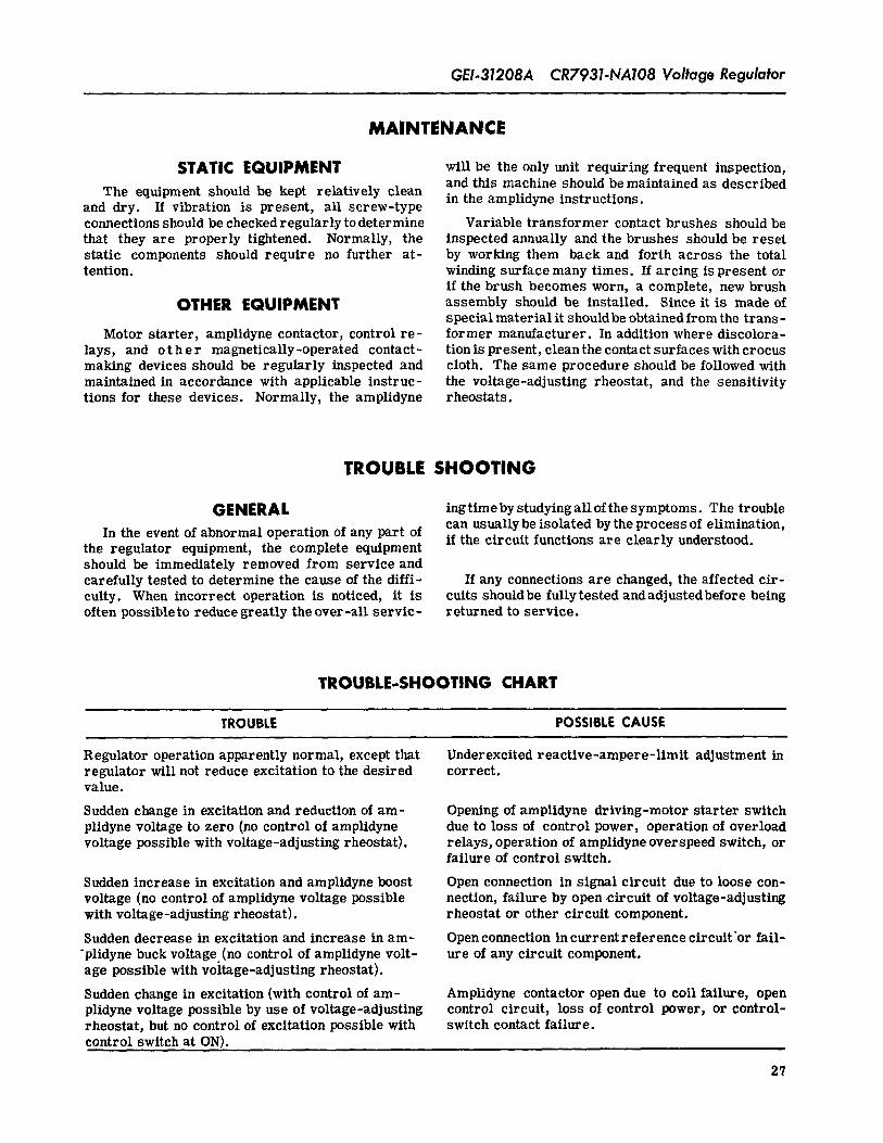
GEI-31208A CR7931-NA108 Voltage Regulator
MAINTENANCE
STATIC EQUIPMENT will be the only unit requiring frequent inspection,and this machine should be maintained as described
The equipment should be kept relatively cleanin the amplidyne instructions.and dry. If vibration is present, all screw-type
connections should be checked regularly to determine Variable transformer contact brushes should bethat they are properly tightened. Normally, the inspected annually and the brushes should be resetstatic components should require no further at- by working them back and forth across the totaltention, winding surface many times. If arcing is present or
if the brush becomes worn, a complete, new brushOTHER EQUIPMENT assembly should be installed. Since it is made of
special material it should be obtained from the trans-Motor starter, amplidyne contactor, control re- former manufacturer. In addition where discolora-
lays, and o t h e r magnetically-operated contact- tion is present, clean the contact surfaces with crocusmaking devices should be regularly inspected and cloth. The same procedure should be followed withmaintained in accordance with applicable instruc- the voltage-adJusting rheostat, and the sensitivitytions for these devices. Normally, the amplidyne rheostats.
TROUBLE SHOOTING
GENERAL ingtimeby studying all of the symptoms. The troublecan usually be isolated by the process of elimination,In the event of abnormal operation of any part ofif the circuit functions are clearly understood.the regulator equipment, the complete equipment
should be immediately removed from service andcarefully tested to determine the cause of the diffi- If any connections are changed, the affected cir-cuity. When incorrect operation is noticed, it is cuits shouidbe fully tested andadjustedbefore beingoften possible to reduce greatly the over-all servic- returned to service.
TROUBLE-SHOOTING CHART
TROUBLE POSSIBLE CAUSE
Regulator operation apparently normal, except that Underexcited reactive-ampere-limit adjustment inregulator will not reduce excitation to the desired correct.value.
Sudden change in excitation and reduction of am- Opening of amplidyne driving-motor starter switchplldyne voltage to zero (no control of amplidyne due to loss of control power, operation of overloadvoltage possible with voltage-adjusting rheostat), relays, operation of amplidyne overspeed switch, or
failure of control switch.
Sudden increase in excitation and amplidyne boost Open connection in signal circuit due to loose con-voltage (no control of amplidyne voltage possible nection, failure by open circuit of voltage-adjustingwith voltage-adjusting rheostat), rheostat or other circuit component.
Sudden decrease in excitation and increase in am- Open connection in current reference circuit'or fail-
'plidyne buck voltage. (no control of amplidyne volt- ure of any circuit component.age possible with voltage-adjusting rheostat).
Sudden change in excitation (with control of am- Amplidyne contactor open due to coil failure, openplidyne voltage possible by use of voltage-adjusting control circuit, loss of control power, or control-rheostat, but no control of excitation possible with switch contact failure.control switch at ON).
27
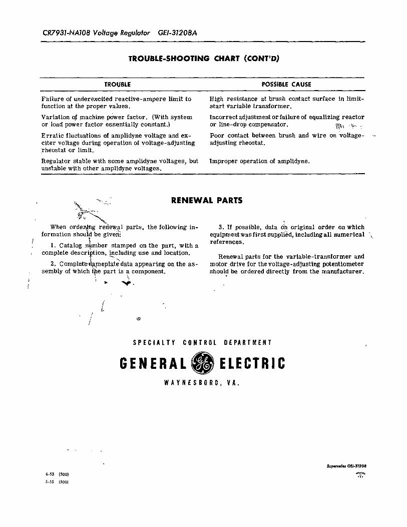
CR7931-NA108 Voltage Regulator GEI-31208A
TROUBLE-SHOOTING CHART (CONT'D,)
TROUBLE POSSIBLE CAUSE
Failure of underexcited reactive-ampere limit to High resistance at brush contact surface in limit-function at the proper values, start variable transformer.
Variation o_f machine power factor. (With system Incorrect adjustment or failure of equalizing reactor
or load power factor essentially constant.) or line-drop compensator. _,_ ,?:_
Erratic fluctuations of amplidyne voltage and ex- Poor contact between brush and wire on voltage-citer voltage during operation of voltage-adjusting adjusting rheostat.rheostat or limit.
Regulator stable with some amplidyne voltages, but Improper operation of amplidyne.unstable with other amplidyne voltages.
_ RENEWALPARTS
When orde_mg re_'ew_al parts, the following in- 3. If possible, data dh original order on which
formation shou_ be given _'x,. equipment was first supplied, including all numerical '_1. Catalog number stamped on the part, with a references.
complete descri_tion_ _cluding use and location. Renewal parts for the variable-transformer and
2. Complet_meplatedata appearing on the as- motor drive for thevoltage-adjusting potentiometersembly of which toe part is a component, should be ordered directly from the manufacturer.
\
f
t
f/
SPECIALTY CONTROL DEPARTMENT .,
GENERAL ELECTRICWAYNESBORO, VA.
$uperNde, GEI.31208
6.53 (500) _Z '''°
5-55 (500)
Recommended