CONSTRUCTION ROBOTICS RESEARCH AT PURDUE
Miroslaw J. Skibniewski
Division of Construction Engineering and ManagementSchool of Civil Engineering
Purdue UniversityWest Lafayette, Indiana 47907, U.S.A.
1 SUMMARY
Purdue University research on the application of robotics toconstruction began in the summer of 1986. It is based on the
assumption that construction can benefit from the advanced
automation technology available now in manufacturing. The
current work activity spans in three directions:
a. Design of a prototype Automated Construction Worker (ACW)for the performance of repetitive surface tasks.
b. Design and evaluation of Flexible Construction Systems.
c. Design of computerized decision aids for robot implemen-tation.
Each of these research areas is presented in some detail.
2 AUTOMATED CONSTRUCTION WORKER
The concept of an Automated Construction Worker (ACW) is beingdeveloped. The ACW robot will perform a series of similar
building surface treatment tasks, utilizing similar process
control strategy, but different, adequate for each task,robot-arm tool effectors. This research aims at identifying
and performance of the ACW robot system's intermediate andfinal integration objectives, as well as the testing and simu-
lation of real construction job site work assignments.
The ACW multi-task robotic system will utilize commerciallyavailable hardware components which are standard in current
industrial robotic systems. This should eliminate a duplica-
tion of effort in the designing and assembling of the
hardware, as well as provide us with the system at a lower
cost. However, some non-standard, sensor-driven robot control
solutions must be designed specifically for this application.
Our experimental system will consist of an AutomaticallyGuided Vehicle (AGV), PUMA 560 manipulator with wrist mounted
camera and ultrasonic range sensors. Additionally, there willbe stationary camera and ultrasonic sensors located on the AGV
138
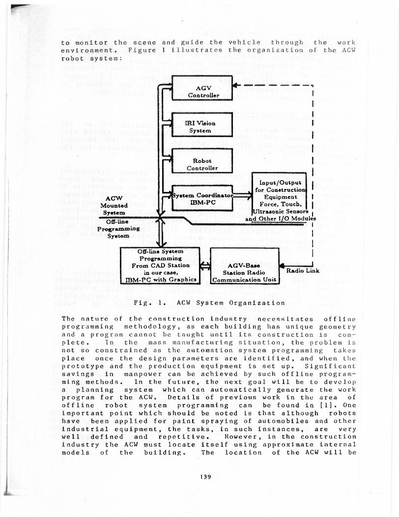
to monitor the scene and guide the vehicle through the work
environment . Figure 1 illustrates the organization of the ACW
robot system:
AGVController
IRI VisionSystem
RobotController
-- - - - -"I
Input /Output Ifor Construction
ACW yetem Coordinator Equipment
Mounted 18M-PC Force, Touch, '
System U ltrasonic SensorsOff line and Other I/O Modules
programmingSystem
off-line SystemProgramming
From CAD Station AGV-Basein our case, Station Radio Radio Link
IBM-PC with Graphics Communication Unit
Fig. 1. ACW System Organization
The nature of the construction industry necessitates offlineprogramming methodology, as each building has unique geometry
and a program cannot be taught until its construction is com-
plete. In the mass manufacturing situation, the problem is
not so constrained as the automation system programming takes
place once the design parameters are identified, and when theprototype and the production equipment is set up. Significant
savings in manpower can be achieved by such offline program-
ming methods. In the future, the next goal will be to developa planning system which can automatically generate the workprogram for the ACW. Details of previous work in the area of
offline robot system programming can be found in [1]. One
important point which should be noted is that although robots
have been applied for paint spraying of automobiles and other
industrial equipment, the tasks, in such instances, are verywell defined and repetitive. However, in the construction
industry the ACW must locate itself using approximate internal
models of the building. The location of the ACW will be
139
calculated from sensing features such as walls, corners, ven-tilation ducts, windows, and the like. Once the ACW is
correctly located, then the application of the necessary fin-ishing material or operation may be initiated. This problem of
locating the ACW-based internal models and sensing is similar
to that of a multi-sensor based industrial robot. Current
construction environments are chaotic and dusty . It is neces-sary to develop passive and active schemes for the cleaning of
the camera lenses and coping with the dusty environment.
AGV Mounted Sensing System:
The AGV mounted sensing equipment will consist of an IRI
vision system and four cameras . The vision system will
directly communicate with an industrial grade IBM Personal
Computer (PC), which will be the system coordinator for the
ACW robot.
The system coordinator will analyze the 2D visual informationobtained from the vision module to reconstruct 3D scene infor-
mation to guide the AGV and or the robot. Some description ofour past work on visual servoing of robots using 2D informa-
tion can be found in [2]. The task of the system coordinator
will be to fuse sensor data from the vision system, the ultra-
sonic system and from other binary sensors such as proximity
sensors for collision detection, etc. The coordinator willalso be responsible for input-output interface between the
various ACW end effectors and the ACW itself.
Model-Based Programming for the ACW:
The ACW will be programmed through a CAD workstation asopposed to being programmed on the spot via teach/playback
schemes. This will enable an architect to create a designdatabase which can be directly utilized by a construction
engineer to generate ACW programs control in batch
production-like situation [3].
Brief Description of Hardware:
The following commercially available hardware will be utilized
in the construction of the ACW system:
- "PUMA 560" Robot: The robot has six degrees of freedom andwill have various applicators mounted at the manipulator
wrist. The robot is programmed via VALII language [41
utilizing transforms. The system coordinator will issue
transforms which the end-effector has to accept.
- "US Robot" AGV: The robot is able to carry up to 250pounds payload. Current system will tract a reflectivetape placed on the ground. The system will be directed
from the system coordinator once visual information is
I
140
gathered. The AGV is programmed via a radio link from a
base station.
- "IRI" Vision Module: This is a 2D binary/grey level imageprocessing system. It offers development environment for
new algorithms . This will allow to adopt the appropriate
image processing and recognition techniques for several
different surface applications.
- "Lord" Force Sensor: A wrist force sensor will be mounted
on the PUMA robot to sense contact forces. This will allow
the manipulator to perform calibration operations by making
contact with the building walls, or during refilling opera-
tions and end-effector change operations. In such
instances force information is essential to verify the com-pletion of a series of contact sequences or compliant
motions [S].
- "Lord" Tactile Sensor: The task of the tactile sensor is
to verify that the parts in the gripper are in position andtheir orientation is accurately known. Therefore, themotions of the robot tools can be accurately predicted.
This will allow precision operations during calibration and
loading/unloading operations.
- Ultrasonic Sensor: Ultransonic sensor will be used tomeasure approximately distance between the robot and the
walls and other obstacles. Information from the ultrasonic
sensor and the vision will be used to control the position
and orientation of the sealant applicators during the ACW
operations.
- System Coordinator: An industrial grade IBM PC with addi-tional single board sensing and input/output controllers
will be used to control ACW internal functions as well as
for general purpose system programming tasks.
- ACW End Effectors
o "Vacu-Blast" sandblasting gun: One 11 mm rotating
supersonic blast nozzle with a suction device drawing
the abrasive, dust, dirt and accumulated foreign matter
by pneumatic means.
o "Educt-o-matic" portable spotting blast gun by Clemco-Clementina with blast head, abrasive container and dust
filter.
o Ancillary equipment (e.g. 19 mm rubber hose, aircompressor, pressure vessel connecting hardware,
abrasive container).
141
o "Spin Jeti" Robot Cleaning System by National LiquidBlasting Corp. It is a water jet cleaning manipulator
for heavy duty cleaning in industrial applications.
o Jet Spraying manipulator by Tokico America, Inc. Robot-ics Division (part of "Armstar," Automated Finishing
System for paint application to wall surfaces).
o "Surclean 153" surface reflectance meter by "ElcometerInstruments" or similar device for the continuous meas-
urement of wall surface cleaning quality. The results
of the monitoring process will be recorded by a
microprocessor unit and fed back into the robot control
system for decision making.
The ACW system is expected to provide a flexible work tool forthe automated performance of repetitive surface application
tasks. Examples of such tasks include paint spraying, sand-
blasting and polishing. Significant benefits from the ACW
operation can be achieved, including labor savings, improvedwork quality, and the removal of workers from hazardous
environments [6].
3 FLEXIBLE CONSTRUCTION SYSTEMS
A functional model of an industrialized, partially automatedbuilding construction site, including its external facilitiesand relationships is under consideration. The model assumes
removal of a number of some highly repetitive work tasks from
the immediate construction site, providing for their automated
performance at an off-site location. Some of the on-site
operations must be redesigned to meet the robot performance
procedure requirements.
Our research objective includes the development of a designand evaluation methodology for construction work automation.
It will be accomplished by a study of the feasibility of an
automated target building construction system. The target sys-tem contains a relatively large variety of generic operations
and work layout configurations that are commonly applicable to
other operations throughout the construction industry. We are
investigating the possibility of work task integration into
smaller subsystems that can be characterized by sets of analo-
gous work operations. In the long range, this approach can
lead to a fundamentally different building design and con-struction organization system which involves interaction and
interdependence of on-site, proximate, and off-site (prefabri-
cation plant) work processes. Construction will then be per-
formed separately by humans or machines, or by humans and
machines jointly, and coordinated to benefit from the best
features of each.
142
After the integration of relevant tasks into new automated
performance subsystems , a limited number of new configurations
will be designed , analyzed and simulated to estimate their
physical performance . The design and analysis of the subsys-
tem will be determined according to the nature of tasks,
equipment and tasktime required , and the anticipated location
of the work process.
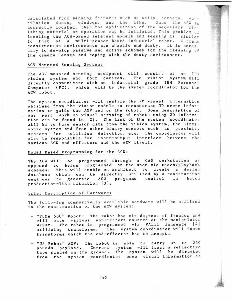
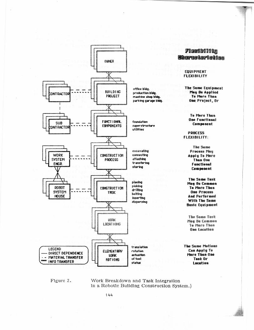
A methodology for integrating generic construction processesinto a multi - level construction system with work automationcapability is presented in Figure 2.
Several estimation measures will be developed for the purpose
of estimating performance of the target robotic construction
system . One such measure can be defined as the Composite
Measure of Complexity ( CMC) for a .n investigated task or pro-
cess . The CMC will be estimated by means of linear regression
and represented in a mathematical function as follows:
CMS = F ( CM,CE,CT , CD,CS)
where
CM = construction material and accessory characteristics
index ( numeric coefficient reflecting material orcomponent purpose dimensions , weight, cost,
comparative strength and survivability in adverseconditions)
CE = variable coefficient reflecting capability and
operating cost of traditional or advanced (NCor robotic ) equipment used in production of
structural component(s)
CT = time required by machine and/or laborers to perform
pre-on-site -erection fabrication
CD = coefficient reflecting logistic effort necessary to
deliver building structural components from thefabrication yard to erection site
CS = coefficient reflecting type and operating cost of
equipment , conditions and time necessary to erectstructural component on site
143
OIJNER
NT RACTORF - ' ,BUILDINGPROJECT
office bldg.production bldg.maohi a shop bldg.parking garage bldg.
1I
SUB f I1NCT I O HRL foundation
NTRACTOR - - ` CDIIPONEHTS superstructure
utilities
sheme%arldslas
EQUIPMENTFLEXIBILITY
The Same EquipmentMay Be AppliedTo More Than
One Project, Or
To More ThanOne Functional
Component
PROCESSFLEXIBILITY:
ROBOTSYSTEMHOUSE
CONSTRUCTIONPROCESS
CONSTRUCTIONTRSK
excavatingconnectingattachingtransferingstorirq
LEGEND- DIRECT DEPENDENCE
I - MATERIAL TRANSFERINFO TRANSFER
placiqPickingdriRaqboltinginsertingdispersi"
UWLDiiT I
ELEMENTRRYuDRK
nDTIONS
translationrotationactuationof toolstatus
The SomeProcess May
Apply To MoreThen One
FunctionalComponent
The Some TaskMeg Be CommonTo More TheoOne Process
And PerformedWith The Sam
Basic Equipment
The Same TaskMeg Be CommonTo More ThanOne Location
The Some MotionsCan Apply To
More Than OneTook OrLocation
Figure 2. Work Breakdown and Task Integrationin a Robotle Building Construction System.)
144
The functions within the CMCs must be estimated for each con-
struction activity at the 'Task' and 'Process' level (see Fig-ure 2), and used in the performance model of robot-aided con-
struction. The CMC functions should be derived by assessing
the level of utility of robotic performance of the examined
operation, and feasibility of other affected activities. The
necessary information for the estimation of these coefficients
can be obtained from the construction organizations and equip-
ment manufacturers and compiled for the use by FCS. The
values of CMC will be used to assess the relative level of
utility of robotizing groups of tasks composing individual
construction processes.
Three major directions of this research will follow:
a. First direction: Ergonomic Data Collection. In thisaspect, ergonomic data should be collected on major
groups of construction operations typical of the targetbuilding system. Consistent systemization of these data
into categories according to the operation's level of
automation potential under job site constraints will con-
stitute a basic research effort, first of this kind for
the construction industry. Examples of important data
collected in this aspect are:
- Types of buildings produced with systems similar tothe target construction system and their currentmarket demands. Information can be obtained from
large construction organizations and prefabricated
component manufacturers.
- Typical work tasks within the target construction sys-tem and their characteristics. Data can be derived
from the analysis of work processes and from contacts
with contractor engineers, equipment manufacturers,
and from surveys of operators engaged in the relevant
work tasks.
- Time and effort requirements for individual task per-formance. Data can be obtained through field surveys
with cooperating contracting firms and from existing
literature (e.g. [71).
- Breakdown of the construction tasks into genericoperations for automated/robotic performance. Thiswill be accomplished by ergonomic analysis of the
analyzed work tasks and by evaluation of relevant
industrial work task performance methods.
b. Second direction: Generic Task and New Work Configura-tion Design. In the second direction, operations in the
target construction system will be analyzed for their
automation potential. Those with the highest relative
145
advantage from this perspective will be selected. Selec-tion criteria will stem from the following areas:
- Relative task simplicity and repetitiveness, forinstance, relatively little requirement for sensory
feedback information and process control;
- Ease of removing the operation from and inserting itback into the construction site; ease of placing it at
a proximate or off-site location for the purpose of
automation;
- Ease of performing the given work process in a
factory-like environment ( e.g. dimensions and weight
of work pieces , accuracy constraints);
- Potential cost effectiveness of the automated workperformance (including labor savings, work safety, and
improved quality benefits). Cost data can be obtainedfrom large construction firms and analyzed with the
methodology developed in previous research by the
investigators.
c. Third direction: Analysis of New Task Configurations.In the third aspect, alternative new work configurations
will be developed. Facility designs of partiallyautomated construction work systems will be developed and
proposed for job site testing. Technical concepts of the
automated equipment will be derived from the existing
prototypes of construction, nuclear
maintenance / inspection and manufacturing solutions (see
e.g. [8]), and adjusted for the construction domain per-
formance. The following three main work environment
alternatives will be considered:
- On-site construction tasks performed by autonomousrobotics and robots working with humans . Data can be
obtained from two main sources: (1) from constructionequipment and robot system manufacturer's, and (2) from
comparative surveys of construction and robotic equip-ment currently being conducted by the investigators.
- Off-site work tasks in automated facilities (flexible,programmable robotic construction shops involving
Flexible Construction System (FCS) concept). Data can
be obtained from the existing conceptual designs of
automated building prefabrication methods [Warszawski
86] and from industrial robotic layouts in the metal-
working and electronics industries [9].
- Transfer tasks that combine on-site and off-sitetasks. Research concentrating on logistics and work
system design for these tasks will consist of
146
interdisciplinary effort utilizing the experience col-
lected to date by industrial , systems, and construc-
tion engineering.
Three performance alternatives with respect to the degree ofhuman input and control over the work task will be considered:
- Human performance of complete task;
- Robotic performance of complete tasks ( autonomous andteleoperated);
- Combined robot -human performance of tasks.
Each alternative will be examined for potential performance
efficiency and productivity , projected system setup cost, and
labor savings. Robot work system models developed in the pro-
cess of this research will be simulated using software
developed for other industrial robot system evaluation [101.
The FCS concept is relatively large in scope and requires theintegration of multiple robotics and other equipment into an
efficient work system . Practical implementation of this con-
cept depends , among other factors, on the success of robotic
construction equipment in the individual work task applica-
tions.
4 EXPERT SYSTEM FOR CONSTRUCTION ROBOT DESIGN
Traditional methods of designing the function of construction
equipment are insufficient for innovative , automated and
robotic equipment to be used on construction sites. Therobotics technology for construction applications and new
methods of improvement of functional design are vigorously
pursued in Japan and should be expected to emerge on U.S. con-
struction sites in the next decade [ 11]. The following rea-
sons for the lack of adequate functional design tools can be
identified:
- All construction robotic equipment is currently availableonly in the prototype stage or still being designed. Con-
sequently , there is no field performance experience forconstruction robots to provide feedback regarding their
functional and cost efficiency;
- The construction site work environment is ill-structured
and constantly changing as the work progresses , thus making
it impossible to transfer the available experience of
robotics applied in well structured , manufacturing plant
environments;
- There is a long lead time for the acquisition and implemen-tation of robotic systems in manufacturing ; it is expected
that this time will be even longer in construction;
147
- There are virtually no consulting professionals availablefor the construction industry who would be knowledgeable of
a broad range of issues related to robotics functional
design for construction applications.
Expert systems have been receiving initial attention amongconstruction equipment designers. Previous work includes
design aspects of construction robot control systems [13]. A
significant potential benefit of the expert system containing
practical and yet unique system design knowledge in the field
of an emerging construction robot application is anticipated.
There is a variety of sources from which different parts ofthe relevant expertise on individual design and implementation
aspects of construction robotics can be obtained . However, at
present a majority of robot system designers is unaware of
such sources of information or is not capable of collectingthe necessary data when faced with a need to make a decision
regarding possible technical innovation involving a robot.Almost no consultants or comprehensive consulting services forspecific applications to construction projects are available,due to lack of experts in all aspects of application decision
making. This has been an important obstacle in the dissemina-
tion of knowledge on robot application potential among robot
manufacturing firms . Development of a computer expert system
containing heuristic knowledge collected and compiled from the
proprietors of this unique expertise and subsequently made
available to robot designer will alleviate this major diffi-
culty in acquiring the state - of-the-art expertise , and will
thus become a breakthrough in the construction application
domain.
The research on development of this expert system combinesexpertise in the design and function of construction equip-
ment , as well as in the design and performance of industrial
robotic systems. It is expected that, besides becomingstate-of-the-art decision aid to robot system designers, the
expert system will enable its designer to acquire a profoundunderstanding of issues and relationships involved in arriving
at a correct and successful design of a construction robot.
Several approaches to expert systems development in manufac-turing for the design of factory environment in which robots
are to work, and for determining functional specifications for
industrial robotic equipment exist ( e.g. [12 ]). One approach
which is highly relevant to construction work environment was
a robot mission oriented method developed for maintenance of
nuclear power plants [8]. Similar methodology will be adopted
in development of the proposed expert system for the func-tional design of construction robots. Purpose and function ofeach robot module will be investigated and compiled in a pre-structured data base for subsequent use in expert system
148
development. Lists of design and implementation experts forrobots of interests have been compiled by the compilation atdata on the existing designs and their field performance.
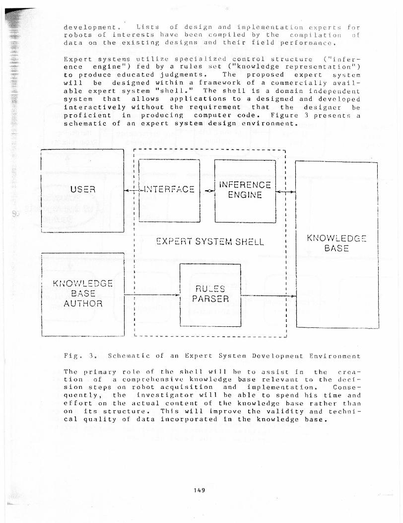
Expert systems utilize specialized control structure ("infer-ence engine") fed by a rules set ("knowledge representation")
to produce educated judgments. The proposed expert system
will be designed within a framework of a commercially avail-
able expert system "shell." The shell is a domain independentsystem that allows applications to a designed and developed
interactively without the requirement that the designer be
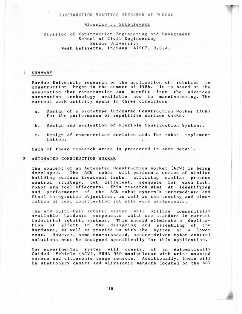
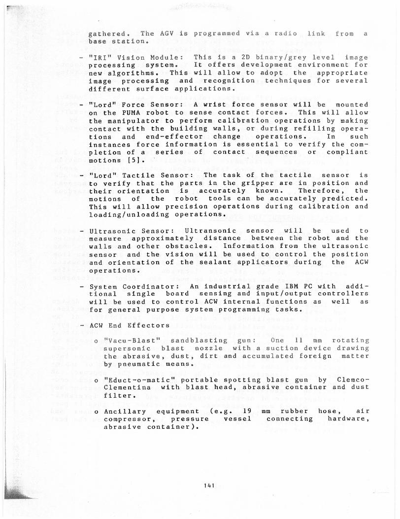
proficient in producing computer code. Figure 3 presents a
schematic of an expert system design environment.
USER
K i\C11Y'1L rDUEBASE
AUTHOR
r -----------------------------
^
' ,_1`NTER,=rACE ,{,- INFERENCEENGINE
EXPERT SYSTEM SHELL
RULE'PARSER
^------------------------
KNOWLEDGEBASE
Fig. 3. Schematic of an Expert System Development Environment
The primary role of the shell will be to assist in the crea-tion of a comprehensive knowledge base relevant to the deci-sion steps on robot acquisition and implementation. Conse-
quently, the investigator will he able to spend his time and
effort on the actual content of the knowledge base rather than
on its structure. This will improve the validity and techni-
cal quality of data incorporated in the knowledge base.
149
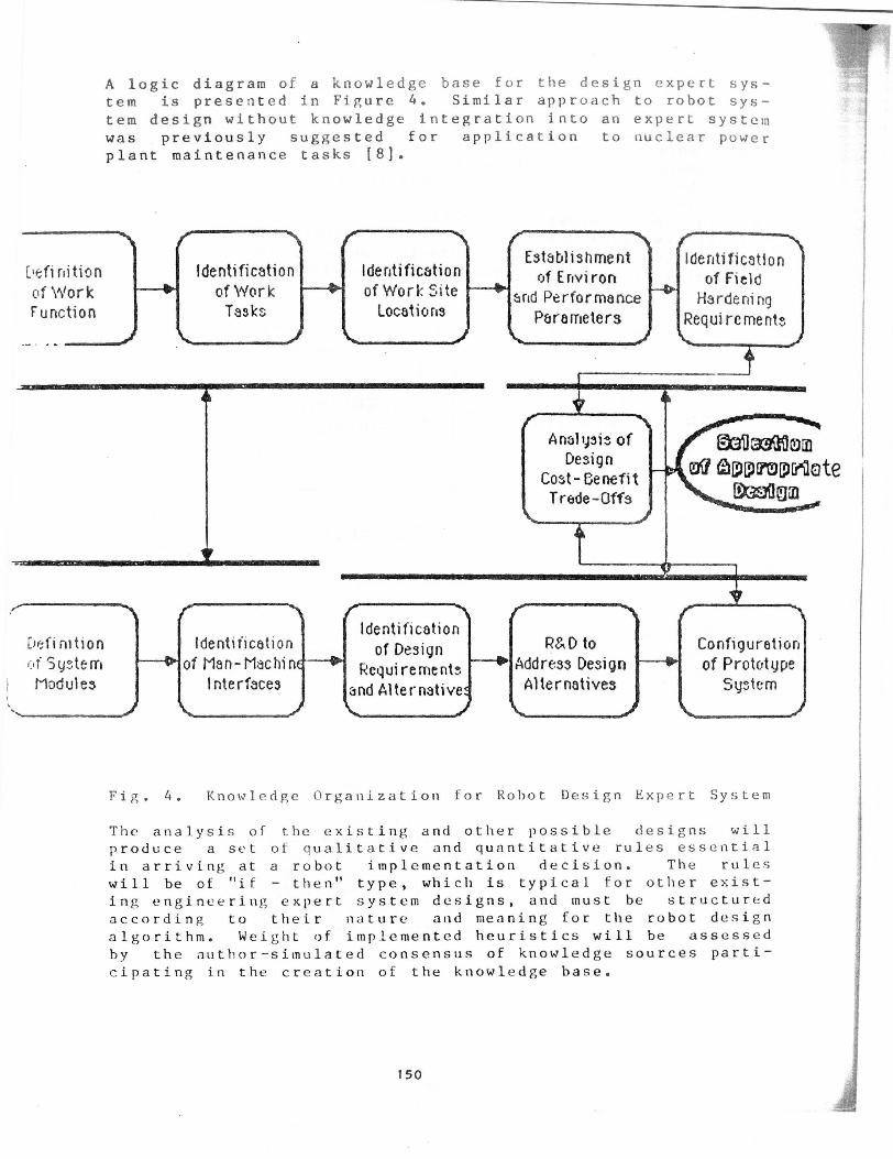
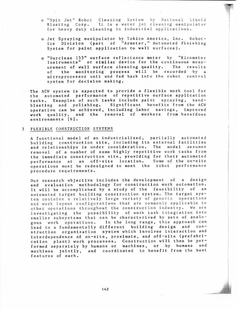
A logic diagram of a knowledge base for the design expert sys-
tem is presented in Figure 4. Similar approach to robot sys-
tem design without knowledge integration into an expert system
was previously suggested for application to nuclear power
plant maintenance tasks [8).
C'efi nitionof WorkFunction
Identificationof WorkTasks-
r-- .Identificationof Work Site
Locations
Establishment ( eritincot '1ionof E nvi ron of field
r and Performance HardeningPararneters Requirements
Anal ysis ofDesign
Cost- BenefitTrade-Offs
r @Aom®4 appnpAote
©m
identificationC'etimtion Identification of Design R&D to Configurationof Sy-,tern 01 of Man-Machin Requirements 01 Address Design of PrototypeModules Interfaces and Alternative Alternatives System
Fig. 4. Knowledge Organization for Robot Design Expert System
The analysis of the existing and other possible designs willproduce a set of qualitative and quantitative rules essential
in arriving at a robot implementation decision. The ruleswill be of "if - then" type, which is typical for other exist-
ing engineering expert system designs, and must be structured
according to their nature and meaning for the robot design
algorithm. Weight of implemented heuristics will be assessedby the author-simulated consensus of knowledge sources parti-
cipating in the creation of the knowledge base.
150
The system should be designed with knowledge modules groupedin specific domain clusters (i.e. technical, economic, and
implementation oriented). The modules will be modifiable and
will have potential for expedient updating of current
application-related expertise. Also, provisions for a wide
range of options for knowledge representation and systemsinference engine operation will be made within the implemented
expert system shell, including bayesian statistics, literal
rule-based production systems, hypothesis testing, andanalysis of uncertain information by "fuzzy set" methodology.
These options will be used, where practical, according to the
nature of knowledge acquired and the desired format ofknowledge output.
The following sources of knowledge should be utilized in pro-ducing the knowledge base for construction robot design deci-
sions:
a. University researchers: construction technology
engineers, robot hardware designers, control system
engineers, engineering economists, ergonomists, technol-ogy forecasters;
b. Industrial robot manufacturers: hardware specialists,control system designers, system design engineers, costengineers, marketing professionals;
c. Independent consultants: e.g., robot installation spe-cialists;
d. Robot system users in manufacturing: stationary indus-
trial robotics for paint spraying, coating, polishing,
foundry and steel mill applications, automatically guidedvehicles (AGVs);
e. Construction robot developers: inspection, testing,reinforcement assembly, surface applications (shotcret-ing, painting, cleaning, polishing).
The results of implementing such an expert system can signifi-cantly contribute to more effective designs of construction
robotics by providing a comprehensive feedback to the robct
designers. This in turn can lead to a more successful appli-
cation experience with robots within construction firms,
creating potential for rapid expansion of this advanced tech-
nology within the construction industry.
5 CONCLUSION
The above three concepts into the working prototypes of con-
struction performance systems will provide a substantial
insight into a wide spectrum of robot application issues in
this domain. New experience and practical data from theseprototype design concepts can be used in planning for futurerobot implementations.
151
6 REFERENCES
(1] Ahmad S. et al.: "Planning of Sensor-Based Robot AidedAssembly," Working paper, Purdue Univ., October 1986.
[2] Shiu Y. et al.: "Using Visual Senvoing of Robotic Tasks,"TR-EE-86, Purdue Univ., October 1986.
(3] Ahmad S. et al.: "Sensor-Based Robot Motion Control forAutomated Assembly,"Proceedings of the 1986 "Autofact"
Conference, Detroit, November 1986.
[4] Shimano B. et al.: "VALII; A New Robot Control System forAutomated Manufacturing," Proceedings of the Robotics and
Automation Conference, Atlanta, March 1984.
[5] Brady M. et al.: "Robot Motion," MIT Press, 1982.
(6] Skibniewski M. et al.: "Cost and Design Impact of RobotConstruction Surface Finishing Work," International Joint
Conference on CAD and Robotics in Architecture and Con-struction, Marseille, June 1986.
[7] "Engineered performance Standards for Real PropertyMaintenance Activities," Warf-Building Handbook, Depart-
ments of the Army, the Navy, and the Air Force, November
1979.
[8] Horst R. et al.: "A Procedure for Developing a Standard-
ized Robotic Maintenance System for Nuclear Power Plants,"
Robo- tics and Remote Handling in Hostile Environments,
American Nuclear Society, Catlinburg, April 1984.
[9] Nof S., editor: "Handbook of Industrial Robotics," JohnWiley & Sons, 1986.
[10] Nof S., Lechtman H.: "Analysis of Industrial Robot Work bythe RTM Method," Industrial Engineering, April 1982.
(11] Oppenheim I., Skibniewski M.: "Robots in Construction,"Encyclopaedia of Robotics, John Wiley & Sons, in print.
[12] Green J.: "Computer Integration of Engineering Design andProduction," National Research Council, National Academy
Press, Washington, 1984.
[13] Fenves S., Rehak D.: "Role of Expert Systems in Construc-tion Robotics," First International Conference on Roboticsin Construction, Carnegie-Mellon University, June 1984.
152
I
Recommended